US11474254B2 - Multi-axes scanning system from single-axis scanner - Google Patents
Multi-axes scanning system from single-axis scannerDownload PDFInfo
- Publication number
- US11474254B2 US11474254B2US16/183,198US201816183198AUS11474254B2US 11474254 B2US11474254 B2US 11474254B2US 201816183198 AUS201816183198 AUS 201816183198AUS 11474254 B2US11474254 B2US 11474254B2
- Authority
- US
- United States
- Prior art keywords
- scanner
- scanning plane
- housing
- fixed
- scan signal
- Prior art date
- Legal status (The legal status is an assumption and is not a legal conclusion. Google has not performed a legal analysis and makes no representation as to the accuracy of the status listed.)
- Active, expires
Links
Images


Classifications
- G—PHYSICS
- G01—MEASURING; TESTING
- G01S—RADIO DIRECTION-FINDING; RADIO NAVIGATION; DETERMINING DISTANCE OR VELOCITY BY USE OF RADIO WAVES; LOCATING OR PRESENCE-DETECTING BY USE OF THE REFLECTION OR RERADIATION OF RADIO WAVES; ANALOGOUS ARRANGEMENTS USING OTHER WAVES
- G01S7/00—Details of systems according to groups G01S13/00, G01S15/00, G01S17/00
- G01S7/48—Details of systems according to groups G01S13/00, G01S15/00, G01S17/00 of systems according to group G01S17/00
- G01S7/481—Constructional features, e.g. arrangements of optical elements
- G01S7/4817—Constructional features, e.g. arrangements of optical elements relating to scanning
- G—PHYSICS
- G01—MEASURING; TESTING
- G01S—RADIO DIRECTION-FINDING; RADIO NAVIGATION; DETERMINING DISTANCE OR VELOCITY BY USE OF RADIO WAVES; LOCATING OR PRESENCE-DETECTING BY USE OF THE REFLECTION OR RERADIATION OF RADIO WAVES; ANALOGOUS ARRANGEMENTS USING OTHER WAVES
- G01S17/00—Systems using the reflection or reradiation of electromagnetic waves other than radio waves, e.g. lidar systems
- G01S17/02—Systems using the reflection of electromagnetic waves other than radio waves
- G01S17/06—Systems determining position data of a target
- G01S17/42—Simultaneous measurement of distance and other co-ordinates
- G—PHYSICS
- G01—MEASURING; TESTING
- G01S—RADIO DIRECTION-FINDING; RADIO NAVIGATION; DETERMINING DISTANCE OR VELOCITY BY USE OF RADIO WAVES; LOCATING OR PRESENCE-DETECTING BY USE OF THE REFLECTION OR RERADIATION OF RADIO WAVES; ANALOGOUS ARRANGEMENTS USING OTHER WAVES
- G01S17/00—Systems using the reflection or reradiation of electromagnetic waves other than radio waves, e.g. lidar systems
- G01S17/88—Lidar systems specially adapted for specific applications
- G01S17/93—Lidar systems specially adapted for specific applications for anti-collision purposes
- G01S17/931—Lidar systems specially adapted for specific applications for anti-collision purposes of land vehicles
- G—PHYSICS
- G02—OPTICS
- G02B—OPTICAL ELEMENTS, SYSTEMS OR APPARATUS
- G02B26/00—Optical devices or arrangements for the control of light using movable or deformable optical elements
- G02B26/08—Optical devices or arrangements for the control of light using movable or deformable optical elements for controlling the direction of light
- G02B26/10—Scanning systems
- G02B26/12—Scanning systems using multifaceted mirrors
- G—PHYSICS
- G02—OPTICS
- G02B—OPTICAL ELEMENTS, SYSTEMS OR APPARATUS
- G02B27/00—Optical systems or apparatus not provided for by any of the groups G02B1/00 - G02B26/00, G02B30/00
- G02B27/10—Beam splitting or combining systems
- G02B27/14—Beam splitting or combining systems operating by reflection only
- G02B27/143—Beam splitting or combining systems operating by reflection only using macroscopically faceted or segmented reflective surfaces
- G—PHYSICS
- G05—CONTROLLING; REGULATING
- G05D—SYSTEMS FOR CONTROLLING OR REGULATING NON-ELECTRIC VARIABLES
- G05D1/00—Control of position, course, altitude or attitude of land, water, air or space vehicles, e.g. using automatic pilots
Definitions
- the present descriptionrelates generally to detecting obstacles using scanning systems, and more particularly, but not exclusively, detecting obstacles using laser scanning systems of autonomous or semi-autonomous vehicles.
- Laser range findersuse light detection and ranging (LIDAR) to measure a distance to a target.
- LIDARlight detection and ranging
- Single-axis laser range findersproject a laser beam in one scan direction.
- Some single-axis laser range finderscan be configured to rotate the single-axis laser beam, creating an angular scanning plane.
- These single-axis scannersare often attached to autonomous or semi-autonomous vehicles to detect obstacles so these vehicles can navigate safely in the environment in which they operate.
- a scanneris often preferred because it can provide an angular detection range of up to 360 degrees.
- a multi-axes scanning systemincludes a single-axis scanner and at least one reflector.
- the scannerincludes an emitter that is capable of projecting a single-axis signal.
- the scanneris also capable of rotating the single-axis signal within a single annular plane to create a main scanning plane.
- the at least one reflectoris arranged to receive and reflect a portion of the scan signal to create one or more secondary scanning planes, different from the main scanning plane.
- the scannercan be a single-axis laser range finder, e.g., a LIDAR scanner.
- the scannercan also be configured to rotate a signal generating emitter about a rotation axis and within an annular plane, with an angular range of up to 360 degrees.
- the at least one reflectorcan be configured to reflect at least a portion of the scan signal from the emitter at a downward angle.
- the at least one reflectorcan be configured to reflect at least a portion of the scan signal from the emitter in a travel direction.
- the at least one reflectorcan be configured to reflect at least a portion of the scan signal from the emitter to form at least one secondary scanning plane above or beneath the main scanning plane.
- the at least one reflectorcan have at least one flat surface, contours, or combinations thereof.
- the systemmay use a single reflector or a plurality of reflectors.
- a multi-axes scanning systemincludes a housing, a single-axis scanner, and at least one reflector.
- the scanner and the at least one reflectorcan be maintained and/or secured in the housing in a fixed orientation.
- the scanneris capable of projecting a single-axis scan signal that is rotated within an annular plane.
- the at least one reflectoris oriented with respect to the scanner to receive and reflect a portion of the scan signal into multiple directions, thus adding multiple scanning axes.
- the systemforms a main scanning plane coplanar with the annular plane.
- the at least one reflectorforms at least one secondary scanning plane that is not coplanar with the annular plane.
- the single-axis scannercan be a single-axis scan laser range finder.
- the scannercan be configured to rotate the single-axis scan signal within an annular plane, with an angular scan range of up to 360 degrees.
- the scannercan be configured to rotate the single-axis scan signal within an annular plane, with an angular scan range of up to 270 degrees.
- the at least one reflectorcan be configured to reflect at least a portion of the scan signal at a downward angle.
- the at least one reflectorcan be or include at least one mirror.
- the at least one reflector or mirrorcan include at least one flat surface and/or at least one contoured surface.
- the at least one reflectorcan be or include a plurality of mirrors.
- the housingincludes a lateral opening or window configured to enable the main scanning plane to pass through the housing.
- the housingincludes one or more openings or windows configured to enable the at least one secondary scanning plane to pass through the housing.
- the at least one secondary scanning planepasses through the housing beneath the main scanning plane.
- a vehiclehaving a multi-axes scanning system.
- the scanning systemincludes a housing, a single-axis scanner, and at least one reflector.
- the scanner and the at least one reflectorcan be secured and/or maintained in the housing in a fixed orientation.
- the scanneris capable of projecting a single-axis scan signal and rotating the single-axis signal within an annular plane.
- the at least one reflectoris oriented to receive and reflect a portion of the scan signal into multiple directions, thus adding multiple scanning axes.
- the vehiclecan be autonomous or semi-autonomous.
- the housingis mounted to the front of the vehicle.
- the vehiclecan be a two-wheeled vehicle.
- the systemforms a main scanning plane coplanar with the single annular plane.
- the at least one reflectorforms at least one secondary scanning plane that is not coplanar with the main scanning plane.
- the housingincludes a lateral opening or window configured to enable the main scanning plane to pass through the housing.
- the housingincludes one or more openings or windows configured to enable the at least one secondary scanning plane to pass through the housing.
- the at least one secondary scanning planepasses through the housing beneath the main scanning plane.
- the scannercan be a single-axis scan laser range finder.
- the scannercan also be configured to rotate the single-axis scan signal within annular plane with an angular range of up to 360 degrees.
- the at least one reflectorcan be configured to reflect at least a portion of the rotating single-axis scan signal at a downward angle.
- the at least one reflectorcan include at least one flat surface, contoured surface, or combinations thereof.
- the systemmay include a plurality of reflectors and/or mirrors.
- the at least one reflector and/or mirroris configured to reflect a portion of the received scanning plane at a downward angle such that the scanning plane scans the surface on which the vehicle is moving at a distance of 0 to 30 cm from a front of the vehicle.
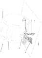
- FIG. 1is a perspective view of an embodiment of a vehicle including a multi-axes scanning system, according to aspects of the inventive concepts
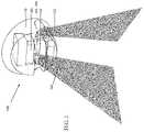
- FIG. 2is a detailed diagram of an embodiment of a multi-axes scanning system of FIG. 1 , according to aspects of the inventive concepts;
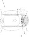
- FIG. 3is a top view perspective view of the vehicle including the multi-axes scanning system of FIG. 1 , according to aspects of the inventive concepts;
- FIG. 4is a front view perspective view of the vehicle including the multi-axes scanning system of FIG. 1 , according to aspects of the inventive concepts;
- FIG. 5is a side view perspective view of the vehicle including the multi-axes scanning system of FIG. 1 , according to aspects of the inventive concepts.
- FIG. 6provides an embodiment of control elements configured to control the vehicle in response to multi-axes scanning system information, according to aspects of the inventive concepts.
- inventive conceptswill be described more fully hereinafter with reference to the accompanying drawings, in which some exemplary embodiments are shown.
- the inventive conceptsmay, however, be embodied in many different forms and should not be construed as limited to the exemplary embodiments set forth herein.
- first, second, etc.may be used herein to describe various elements, these elements should not be limited by these terms. These terms are used to distinguish one element from another, but not to imply a required sequence of elements. For example, a first element can be termed a second element, and, similarly, a second element can be termed a first element, without departing from the scope of the present invention.
- the term “and/or”includes any and all combinations of one or more of the associated listed items. The term “or” is not used in an exclusive or sense, but in an inclusive or sense.
- Autonomous and/or semi-autonomous vehiclesoften use scanners to gather information about the environment in which they navigate so they can safely move around and operate within the environment.
- the scannertypically projects parallel to the surface on which the vehicle is moving, e.g., a ground surface. Consequently, the scanner has difficulties detecting changes in the surface, such as slope angles, steps, cliffs, and pot-holes.
- the scanneralso often fails to detect obstacles on the surface in the immediate vicinity of the vehicle.
- some autonomous and/or semi-autonomous vehiclesmay be equipped with multiple single-axis scanners to add multiple planes of detection.
- Multi-axes laser range finderscan also be used; however, these tend to be very expensive and not feasible for commercial purposes.
- Point cloud sensors and stereo camerascan offer an effective method for identifying obstacles, such as cliffs, potholes, and changes in surface slope, but these sensors also have difficulties in detecting obstacles in close proximity to the vehicle.
- a scanning systemthat uses a single-axis laser scanner for scanning across multiple axes would be beneficial and cost-effective.
- FIG. 1the present disclosure provides a vehicle 10 having a multi-axes scanning system 100 , according to aspects of the inventive concepts.
- FIG. 2is a detailed diagram of an embodiment of a multi-axes scanning system 100 of FIG. 1 , according to aspects of the inventive concepts.
- FIG. 3is a top view perspective view of the vehicle including the multi-axes scanning system of FIG. 1 .
- FIG. 4is a front view perspective view of the vehicle including the multi-axes scanning system of FIG. 1 .
- FIG. 5is a side view perspective view of the vehicle including the multi-axes scanning system of FIG. 1 .
- the vehicle 10can be an autonomous or semi-autonomous vehicle.
- the multi-axes scanning system 100can be affixed to, disposed at, and/or integral with a front of the vehicle 10 and above a ground plane or ground surface 50 , as is shown in FIGS. 1 and 3-5 .
- the scanning system 100can be located at a height above the ground surface 50 and less than half of the height of the vehicle 10 .
- the vehicle 10has a generally spherical or disc shape and includes a right wheel 12 and a left wheel 14 and the multi-axes scanning system 10 is disposed between the right and left wheels 12 , 14 .
- the vehicle 10can be, as an example, a mobile carrier vehicle.
- the multi-axes scanning system 100is configured to provide multiple scanning planes from a single scanning beam, which can be output by an emitter of a scanner 130 .
- the multiple scanning planescan include a first, main scanning plane 120 and one or more secondary scanning planes 122 , 124 , which can be angular scanning planes.
- the main scanning plane 120extends in a travel direction and the one or more secondary angular scanning planes 122 , 124 also extend in the travel direction, but at an angle and at least partially beneath the first angular plane 120 .
- FIGS. 1 and 3-5Such an embodiment is shown in FIGS. 1 and 3-5 .
- the multi-axes scanning system 100can include a housing 110 surrounding beam-forming and/or output elements of the multi-axes scanning system 100 , e.g., an emitter and receiver and/or detector.
- the multi-axes scanning system 100can include a single-axis scanner 130 , which can be oriented within housing 110 .
- the single-axis scanner 130can be a scanner that rotates a scanning beam, e.g., a laser beam, about a rotation axis and in a scanning plane that is orthogonal to the rotation axis.
- the scanning planecan be an annular scanning plane.
- the scanning system 100can include one or more reflectors (e.g., one or more mirrors) 142 , 144 and the housing 110 that maintains the one or more reflectors in a fixed orientation with respect to the rotating scanning beam 130 .
- one or more reflectorse.g., one or more mirrors
- reflectors (or mirrors) 142 , 144reflect the scan signal to produce the secondary scanning planes 122 , 124 , which can be angular scanning planes.
- the housing 110includes a lateral opening or window configured to enable the main scanning plane 120 to pass through the housing 110 .
- the housing 110can also include openings or windows for passage of the reflected scanning planes from the mirrors 142 , 144 through the housing 110 .
- the one or more openings or windowsenable the at least one secondary scanning plane 122 , 124 to pass through the housing 110 .
- the secondary scanning planesare reflected through in the travel direction and toward the ground surface 50 .
- the at least one secondary scanning plane 122 , 124passes through the housing 100 beneath the main scanning plane 120 , and in the travel direction.
- the scanner 130can be a single-axis laser range finder capable of rotating a single-axis scan signal or beam within a single annular plane—the main annular plane.
- the scanner 130can be a LIDAR laser scanner, as an example.
- the scanner 130can be configured to rotate the single-axis scan signal within the main annular plane within a range of scan angles.
- the range of scan anglescan result in an angular scan range of at least 270 degrees to 360 degrees.
- the angular scan rangecan be between about 180 degrees and about 360 degrees.
- the angular scan rangecan be between about 90 degrees and 360 degrees.
- the angular scan rangecan be between 90 degrees and up to about 270 degrees.
- the scanner 130can be oriented so that the main annular scan plane 120 is substantially parallel to the ground surface 50 .
- the scanning system 100is capable of projecting a single-axis scan signal or beam in a travel direction that is horizontal to the ground surface 50 and orthogonal to the axis of rotation of the scanning beam.
- the travel directioncan be a forward direction or a backward direction depending on whether or not the vehicle 10 has a defined front and back.
- the multi-axes scanning system 100includes a plurality of reflectors (e.g., mirrors), including reflectors 142 , 144 oriented rearward of the single-axis scanner or rearward of the axis of rotation of the single-axis scanner.
- the plurality of reflectorscan either be or include one or more flat surfaces, contours, or a combination thereof.
- the reflectors 142 , 144can be maintained in a fixed position relative to the scanner 130 within housing 110 .
- the plurality of reflectors 142 , 144is oriented to receive one or more portions of the rotating scan signal and reflect the received portions in one or more downward directions towards the ground surface 50 on which the vehicle 10 is moving to form one or more secondary scanning planes 122 , 124 .
- the secondary scanning planescan be angular scanning planes.
- the reflectors 142 , 144can be oriented to form the secondary scanning planes 122 , 124 beneath the main angular scanning plane 120 , and angled in the travel direction toward the ground surface 50 .
- the plurality of reflectorsare arranged to reflect the portions of the scan signal at a downward angle such that the secondary scanning planes scan the ground surface 50 at a distance of 0 to 30 cm from a front of the vehicle 10 .
- FIG. 6provides an embodiment of control elements configured to control the vehicle in response to multi-axes scanning system information, according to aspects of the inventive concepts.
- the scanning system 100includes a receiver and or detector that receives reflections of the output scan signal or beam. From the received signals, distance information can be determined.
- the autonomous or semi-autonomous vehicle 10uses the information from the scanning system 100 to detect changes in the terrain, such as cliffs, curbs, stairs, objects, obstacles, or a pitch of the surface 50 .
- a controller 150 of the vehiclereceives information from the scanning system 100 , in the form of detection signals, and uses information in the detection signals to control a movement of the vehicle 10 through a drive system 160 .
- the controlcan communicate with the drive system to cause the vehicle to accelerate, decelerate, pause, stop, turn, and/or change directions.
- Information from the scanner and/or vehiclecan be stored in one or more storage devices 170 .
- Such controlled vehicle movementcan include acceleration, deceleration, and/or turning.
- the controller 150uses the scanning system 100 to first detect a distance to the surface 50 .
- the controller 150uses the total distance measured by the scanner system 100 , the known distance between the scanner 130 and mirrors 142 , 144 , and the mirrors' known angles of occurrence to determine a distance from the vehicle 10 to where the secondary scanning planes 122 , 124 impinge on the scanned ground surface 50 .
- the scanning system 100scans the ground surface 50 multiple times, and a low pass filter is used to filter noise from the multiple received signals or reflections. After the noise is filtered from the received signals, the controller determines an average distance to the scanned portion of the ground surface 50 .
- the controller 150can be configured to continuously determine an average distance to a scanned portion of the ground surface 50 as the vehicle 10 moves across the ground surface 50 .
- the controller 150can be configured to compare the determined average distances with upper and lower range thresholds. Once a change in the determined average distance exceeds an upper or lower threshold, the controller 150 concludes that the scanning system 100 has detected a change in the environment, such as a cliff, curb, stair, pothole, or change in the pitch of the surface.
- a lower threshold of ⁇ 5 cmmay be used.
- the controllerconcludes that the scanner 130 has detected a drop-off in the surface.
- the controllerconcludes that the scanner has detected a raise in elevation of the surface, e.g., a curb. Once these changes are detected, the controller controls the movement of the vehicle 10 accordingly.
- the vehicle 10can use an Inertial Measurement Unit along with the scanning system 100 to help determine upper thresholds, lower thresholds, and tilt relative to the road or ground surface 50 .
- the information detected by the scanning system 100can be communicated to the controller 150 and for controlling the drive system, and can also be used for continuously building a three-dimensional map of the environment, instantaneous object detection, or a combination thereof.
- the multi-axes scanning system 100can comprise a housing 110 , single-axis scanner 130 , and a plurality of reflectors 142 , 144 .
- the housing 110can be configured to encompass the scanner 130 and reflectors.
- the scanning system 100is capable of projecting a single-axis scan signal.
- the scanner 130is also capable of rotating the single-axis scan signal along a single annular plane, the main annular plane.
- the scannercan be configured to rotate the single-axis scan signal within the annular plane with an angular scan range of at least 270 degrees, and optionally up to 360 degrees.
- the plurality of reflectors 142 , 144can be oriented within the housing 100 rearward of the single-axis scanner 130 , or its axis of rotation.
- the plurality of reflectors 142 , 144can be oriented to receive and reflect a portion of the rotating scan signal.
- the plurality of reflectors 142 , 144are angled downward to reflect the received scan signal from the scanner 130 towards the ground surface 50 on which the vehicle 10 is moving.
- the plurality of reflectors 142 , 144can either be flat surfaced, contoured, or a combination thereof.
- the plurality of mirrors 142 , 144can be oriented to reflect the received scan signal to scan the ground surface 50 at a distance of 0 to 30 cm from a front of the vehicle 10 .
- FIG. 3provides a top view of a multi-axes scanning system 100 fixed to a vehicle 10 , similar to FIG. 1 .
- the vehicle 10has a generally spherical or disc shape and includes two wheels 12 , 14 .
- the vehicle 10can be an autonomous or semi-autonomous vehicle.
- the multi-axes scanning system 100is fixed to or located at a front portion of the vehicle 10 .
- the multi-axes scanning system 100includes a housing 110 , a single-axis scanner 130 , and a plurality of reflectors (e.g., mirrors) 142 , 144 .
- the scanning system 100is capable of projecting a single-axis scan signal in multiple planes, including multiple forward projecting planes.
- the scanner 130is capable of rotating the single-axis scan signal in a single, main annular plane to form a main scanning plane.
- the scanneris configured to rotate the single-axis scan signal within the main annular plane with an angular range of at least 270 degrees, in some embodiments.
- the single-axis laser scanner 130rotates horizontally, creating a horizontal annular scanning plane.
- the scanning range of the scannercan be at least 270 degrees, or ⁇ 135 degrees from a center point of the vehicle 10 in the travel direction.
- the full range of the scan 136is shown in FIG. 3 .
- the vehicle's right and left wheels 12 , 14are located right and left of the scanning system 100 at angles of ⁇ 90 degrees and +90 degrees, respectively, from the center point of the vehicle 10 . Therefore, due to the location of the scanner 130 relative to the vehicle wheels 12 , 14 , the scanner 130 is only capable of effectively using 0 degrees to ⁇ 90 degrees of the angular scan range.
- the annular scanning plane 136is “wasted” in that the scanner signal or beam 132 (see FIG. 2 ) cannot not effectively scan for object detection in those scan areas because the scan signal or beam 132 is directed toward the vehicle body. Therefore, the wasted portions of the scan can be considered over-scan portions.
- the reflectors 142 , 144are oriented to intercept the over-scan portions 134 to make use of it in generating the secondary scanning planes 122 , 124 .
- some of the present embodimentsare designed to make efficient use of the overs-scan portions 134 of the scanning plane 136 . This is accomplished by positioning reflectors rearward of the scanner 130 (or at least rearward of the axis of rotation of the scanner 130 ) to reflect segments 134 of the “wasted” scanning portion to create at least one additional scanning plane, as at least one secondary scanning plane. Accordingly, the scanner 130 can detect more information about the vehicle's surrounding environment, particularly with regards to the ground surface 50 immediately in front of the vehicle 10 . Thus, the scanning system 100 creates a cost-effective method for increased obstacle detection without the need to use expensive multi-axes scanners or multiple single-axis scanners on a vehicle.
- the scanning system 130projects an annular scan having an angular range of at least ⁇ 135 degrees from the front of the vehicle.
- Two reflectors 142 , 144are disposed and maintained behind the scanner 130 and configured to reflect a received signal 134 at a downward and forward angle.
- the reflectors 142 , 144are placed such that they receive and reflect portions of the scan ranges 134 that comprises the “wasted” scanning portion.
- the reflected segmentcan be portions of the angular scan at angles between ⁇ 100 degrees to ⁇ 120 degrees from a center point at the front of the vehicle. Other angles can be used in other embodiments.
- the reflectors 142 , 144reflect the received portion of the scanning plane at a downward and forward angle, creating at least one additional (secondary) scanning plane.
- the multi-axes scanning system 100reduces the need for multiple scanners by making efficient use of the previously wasted scanning portions to create at least one additional scanning plane and axis.
Landscapes
- Physics & Mathematics (AREA)
- Engineering & Computer Science (AREA)
- General Physics & Mathematics (AREA)
- Radar, Positioning & Navigation (AREA)
- Remote Sensing (AREA)
- Electromagnetism (AREA)
- Computer Networks & Wireless Communication (AREA)
- Optics & Photonics (AREA)
- Aviation & Aerospace Engineering (AREA)
- Automation & Control Theory (AREA)
- Optical Radar Systems And Details Thereof (AREA)
Abstract
Description
Claims (22)
Priority Applications (1)
| Application Number | Priority Date | Filing Date | Title |
|---|---|---|---|
| US16/183,198US11474254B2 (en) | 2017-11-07 | 2018-11-07 | Multi-axes scanning system from single-axis scanner |
Applications Claiming Priority (2)
| Application Number | Priority Date | Filing Date | Title |
|---|---|---|---|
| US201762582760P | 2017-11-07 | 2017-11-07 | |
| US16/183,198US11474254B2 (en) | 2017-11-07 | 2018-11-07 | Multi-axes scanning system from single-axis scanner |
Publications (2)
| Publication Number | Publication Date |
|---|---|
| US20190137629A1 US20190137629A1 (en) | 2019-05-09 |
| US11474254B2true US11474254B2 (en) | 2022-10-18 |
Family
ID=66328513
Family Applications (1)
| Application Number | Title | Priority Date | Filing Date |
|---|---|---|---|
| US16/183,198Active2041-08-02US11474254B2 (en) | 2017-11-07 | 2018-11-07 | Multi-axes scanning system from single-axis scanner |
Country Status (1)
| Country | Link |
|---|---|
| US (1) | US11474254B2 (en) |
Families Citing this family (4)
| Publication number | Priority date | Publication date | Assignee | Title |
|---|---|---|---|---|
| WO2021131260A1 (en)* | 2019-12-24 | 2021-07-01 | 三菱電機株式会社 | Blocking detection device and blocking detection program |
| US11716522B2 (en) | 2020-08-06 | 2023-08-01 | Piaggio Fast Forward Inc. | Follower vehicle sensor system |
| USD1010699S1 (en) | 2021-09-21 | 2024-01-09 | Piaggio Fast Forward Inc. | Sensor pack |
| USD1034305S1 (en) | 2021-09-21 | 2024-07-09 | Piaggio Fast Forward Inc. | Mobile carrier |
Citations (87)
| Publication number | Priority date | Publication date | Assignee | Title |
|---|---|---|---|---|
| US4127771A (en) | 1975-07-21 | 1978-11-28 | Erwin Sick Gesellschaft Mit Beschrankter Haftung Optik-Elektronik | Optical apparatus |
| US4477184A (en) | 1979-01-19 | 1984-10-16 | Nissan Motor Company, Limited | Obstacle detection system for use in vehicles |
| USH650H (en) | 1988-04-14 | 1989-07-04 | The United States Of America As Represented By The United States Department Of Energy | Double sided circuit board and a method for its manufacture |
| US4864121A (en) | 1987-03-12 | 1989-09-05 | Erwin Sick Gmbh Optik-Elektronik | Light curtain with periodic light transmitter arrangement |
| US4875761A (en) | 1986-10-16 | 1989-10-24 | Erwin Sick Gmbh Optik-Electronik | Light curtain apparatus |
| US4942529A (en) | 1988-05-26 | 1990-07-17 | The Raymond Corporation | Lift truck control systems |
| USD339149S (en) | 1991-12-03 | 1993-09-07 | Nippon Control Industrial Co., Ltd. | Video camera |
| USD364840S (en) | 1993-03-26 | 1995-12-05 | Zexel Corporation | Console for vehicle navigation system |
| US5598263A (en) | 1994-09-13 | 1997-01-28 | Matra Marconi Space France | Light-backscatter measurement device suitable for use on board a craft |
| USD389848S (en) | 1996-07-25 | 1998-01-27 | James Robert S | Vehicular shaped camera |
| US5757501A (en) | 1995-08-17 | 1998-05-26 | Hipp; Johann | Apparatus for optically sensing obstacles in front of vehicles |
| USD395285S (en) | 1996-03-01 | 1998-06-16 | Medivision, Medical Imaging Ltd. | Control unit |
| US5805275A (en) | 1993-04-08 | 1998-09-08 | Kollmorgen Corporation | Scanning optical rangefinder |
| DE19757848A1 (en) | 1997-12-24 | 1999-07-08 | Johann Hipp | Optical detection apparatus |
| US5938710A (en) | 1996-04-03 | 1999-08-17 | Fiat Om Carrelli Elevatori S.P.A. | Selectively operable industrial truck |
| USD416032S (en) | 1996-06-27 | 1999-11-02 | Bakshi Rajeev K | Video surveillance camera housing |
| USD426250S (en) | 1998-12-23 | 2000-06-06 | Slc Technologies, Inc. | Surveillance camera housing |
| US6141105A (en) | 1995-11-17 | 2000-10-31 | Minolta Co., Ltd. | Three-dimensional measuring device and three-dimensional measuring method |
| US6252659B1 (en) | 1998-03-26 | 2001-06-26 | Minolta Co., Ltd. | Three dimensional measurement apparatus |
| USD445818S1 (en) | 1999-05-20 | 2001-07-31 | Point Grey Research Inc. | Trinocular stereo vision camera |
| US6317202B1 (en)* | 1998-11-12 | 2001-11-13 | Denso Corporation | Automotive radar detecting lane mark and frontal obstacle |
| US6363326B1 (en)* | 1997-11-05 | 2002-03-26 | Robert Lawrence Scully | Method and apparatus for detecting an object on a side of or backwards of a vehicle |
| US6392688B1 (en) | 1999-10-04 | 2002-05-21 | Point Grey Research Inc. | High accuracy stereo vision camera system |
| US6429941B1 (en) | 1998-07-14 | 2002-08-06 | Minolta Co., Ltd. | Distance measuring equipment and method |
| GB2383310A (en) | 2001-12-19 | 2003-06-25 | Boss Mfg Ltd | Vehicle switching system control by external sensor |
| US20030116697A1 (en) | 2001-12-20 | 2003-06-26 | Dynapar Corporation | Light curtain mounting system |
| US20040049344A1 (en) | 2002-09-06 | 2004-03-11 | Steven Simon | Object collision avoidance system for a vehicle |
| US20040073359A1 (en) | 2002-01-23 | 2004-04-15 | Hisashi Ichijo | Position control device and position control method of stevedoring apparatus in industrial vehicle |
| US20040246333A1 (en) | 2003-06-03 | 2004-12-09 | Steuart Leonard P. (Skip) | Digital 3D/360 degree camera system |
| US20050030392A1 (en) | 2003-08-07 | 2005-02-10 | Kujin Lee | Method for eliminating blooming streak of acquired image |
| USD508064S1 (en) | 2004-02-06 | 2005-08-02 | Anthony Ramirez | Housing for a camera |
| US20050278098A1 (en) | 1994-05-23 | 2005-12-15 | Automotive Technologies International, Inc. | Vehicular impact reactive system and method |
| US6985212B2 (en) | 2003-05-19 | 2006-01-10 | Rosemount Aerospace Inc. | Laser perimeter awareness system |
| US20060013580A1 (en) | 2000-03-22 | 2006-01-19 | Shigeru Horiguchi | Camera, an image inputting apparatus, a portable terminal device, and a method for transforming the camera configuration |
| US20060012673A1 (en) | 2004-07-16 | 2006-01-19 | Vision Robotics Corporation | Angled axis machine vision system and method |
| US20060072020A1 (en) | 2004-09-29 | 2006-04-06 | Mccutchen David J | Rotating scan camera |
| US20060104800A1 (en) | 2002-11-12 | 2006-05-18 | Steffen Armbruster | Method and system for material transport |
| US20060132644A1 (en) | 2004-02-20 | 2006-06-22 | Dongkai Shangguan | Wafer based camera module and method of manufacture |
| USD524834S1 (en) | 2004-11-12 | 2006-07-11 | Dozier Financial Corporation | External surface configuration of a camera housing |
| USD529528S1 (en) | 2004-05-21 | 2006-10-03 | Trophy Tech, Inc. | Housing for bow mounted camera |
| US20070013779A1 (en) | 2003-08-28 | 2007-01-18 | Jack Gin | Dual surveillance camera system |
| USD541798S1 (en) | 2005-03-11 | 2007-05-01 | Omron Corporation | Display with console for programmable logic controller |
| US7218385B2 (en) | 2004-04-28 | 2007-05-15 | Denso Corporation | Preceding vehicle recognition apparatus |
| US20070177011A1 (en) | 2004-03-05 | 2007-08-02 | Lewin Andrew C | Movement control system |
| US20070181786A1 (en) | 2004-09-28 | 2007-08-09 | Siemens Aktiengesellschaft | Device for monitoring spatial areas |
| US7277118B2 (en) | 1999-08-09 | 2007-10-02 | Fuji Xerox Co., Ltd. | Method and system for compensating for parallax in multiple camera systems |
| US20080001727A1 (en) | 2004-11-15 | 2008-01-03 | Hitachi, Ltd. | Stereo Camera |
| US7322833B1 (en) | 2006-10-31 | 2008-01-29 | Flextronics Ap, Llc | Connection of FPC antenna to PCB |
| US20080084474A1 (en) | 2006-10-10 | 2008-04-10 | Axis Ab | Surveillance camera |
| US20080167819A1 (en) | 1997-10-22 | 2008-07-10 | Intelligent Technologies International, Inc. | Vehicular Environment Scanning Techniques |
| US20080204570A1 (en) | 2007-02-15 | 2008-08-28 | Stephen Schultz | Event Multiplexer For Managing The Capture of Images |
| US7446766B2 (en) | 2005-02-08 | 2008-11-04 | Seegrid Corporation | Multidimensional evidence grids and system and methods for applying same |
| US20090073308A1 (en) | 2003-11-07 | 2009-03-19 | Scimeasure Analytical Systems, Inc. | Apparatuses and Methods for a Camera Head Enclosure Device for Facilitating Improved Imaging |
| US20090184811A1 (en) | 2008-01-23 | 2009-07-23 | Althoff Nicholas K | Methods and system for an impact avoidance system |
| US7583391B2 (en) | 2004-11-19 | 2009-09-01 | School Juridical Person Of Fukuoka Kogyo Daigaku | Three-dimensional measuring apparatus, three-dimensional measuring method, and three-dimensional measuring program |
| USD602931S1 (en) | 2008-11-15 | 2009-10-27 | Motorola, Inc, | Control device for public safety vehicle |
| US20090295053A1 (en) | 2008-05-30 | 2009-12-03 | Production Solutions, Inc. | Adjustable support tooling apparatus |
| USD613341S1 (en) | 2009-07-28 | 2010-04-06 | Hyperkin Inc. | Video game console |
| US20100165155A1 (en) | 2008-12-27 | 2010-07-01 | Hon Hai Precision Industry Co., Ltd. | Camera module with plural imaging units |
| US20100165134A1 (en) | 2006-04-17 | 2010-07-01 | Dowski Jr Edward R | Arrayed Imaging Systems And Associated Methods |
| USD627814S1 (en) | 2009-10-23 | 2010-11-23 | Cheng Uei Precision Industry Co., Ltd. | Wireless webcam |
| US20110037963A1 (en) | 2009-08-17 | 2011-02-17 | Seegrid Corporation | System and method using a multi-plane curtain |
| US7947944B2 (en) | 2008-11-03 | 2011-05-24 | Trimble Navigation Limited | Laser transmitter, laser receiver and method |
| USD642607S1 (en) | 2009-10-27 | 2011-08-02 | Axis Ab | Housing for surveillance camera |
| US20110256800A1 (en) | 2010-03-31 | 2011-10-20 | Jennings Chris P | Systems and methods for remotely controlled device position and orientation determination |
| US8081207B2 (en) | 2006-06-06 | 2011-12-20 | Point Grey Research Inc. | High accuracy stereo camera |
| US8120645B2 (en) | 2008-04-25 | 2012-02-21 | Fuji Jukogyo Kabushiki Kaisha | Stereo camera unit |
| US20120044353A1 (en) | 2010-08-21 | 2012-02-23 | Yan-Hong Chiang | Video radar display system |
| US20120065762A1 (en) | 2010-09-13 | 2012-03-15 | Toyota Motor Engineering & Manufacturing North America, Inc. | Methods For Selecting Transportation Parameters For A Manufacturing Facility |
| US20120075093A1 (en) | 2010-09-29 | 2012-03-29 | Cheng Sou-Yang | Portable remote control device with anti-hidden camera and anti-wiretapper functions |
| US20120154521A1 (en) | 2010-10-26 | 2012-06-21 | Townsend Julie A | 360-degree camera head for unmanned surface sea vehicle |
| US8253777B2 (en) | 2009-03-30 | 2012-08-28 | Hon Hai Precision Industry Co., Ltd. | Panoramic camera with a plurality of camera modules |
| US20120224844A1 (en) | 2011-03-04 | 2012-09-06 | Hon Hai Precsion Industry Co., Ltd. | Camera module |
| US20120242785A1 (en) | 2011-03-24 | 2012-09-27 | Kabushiki Kaisha Topcon | Omnidirectional Camera |
| US8279266B2 (en) | 2009-11-30 | 2012-10-02 | Daniel Theobald | Video system using camera modules to provide real-time composite video image |
| US8290245B2 (en) | 2004-07-01 | 2012-10-16 | Sick Ivp Ab | Measuring apparatus and method for range inspection |
| CN102938978A (en) | 2012-11-28 | 2013-02-20 | 成都航天通信设备有限责任公司 | Thick-ceramic-base printed circuit board processing method |
| US20130044108A1 (en) | 2011-03-31 | 2013-02-21 | Panasonic Corporation | Image rendering device, image rendering method, and image rendering program for rendering stereoscopic panoramic images |
| US8405820B2 (en) | 2010-01-13 | 2013-03-26 | Ricoh Company, Ltd. | Ranging device and ranging module and image-capturing device using the ranging device or the ranging module |
| USD680142S1 (en) | 2011-07-26 | 2013-04-16 | Seegrid Corporation | Multi-camera head |
| US8427472B2 (en) | 2005-02-08 | 2013-04-23 | Seegrid Corporation | Multidimensional evidence grids and system and methods for applying same |
| US20130107011A1 (en) | 2011-10-28 | 2013-05-02 | Samsung Electromechanics Co., Ltd. | Stereo camera module and stereo camera |
| US8439266B2 (en) | 2009-10-30 | 2013-05-14 | Optoelectronics Co. Ltd. | Optical-information-reading apparatus |
| WO2013102212A1 (en) | 2011-12-30 | 2013-07-04 | Seegrid Corporation | Auto-navigating vehicle with field-of-view enhancing sensor positioning and method of accomplishing same |
| US20130257607A1 (en) | 2012-02-21 | 2013-10-03 | Flow-Rite Safety Solutions Inc. | Warning device and collision avoidance system |
| USD697198S1 (en) | 2012-02-17 | 2014-01-07 | Picolife Technologies, Llc | Multi-drug delivery system having cartridge |
| US20150362921A1 (en) | 2013-02-27 | 2015-12-17 | Sharp Kabushiki Kaisha | Surrounding environment recognition device, autonomous mobile system using same, and surrounding environment recognition method |
- 2018
- 2018-11-07USUS16/183,198patent/US11474254B2/enactiveActive
Patent Citations (94)
| Publication number | Priority date | Publication date | Assignee | Title |
|---|---|---|---|---|
| US4127771A (en) | 1975-07-21 | 1978-11-28 | Erwin Sick Gesellschaft Mit Beschrankter Haftung Optik-Elektronik | Optical apparatus |
| US4477184A (en) | 1979-01-19 | 1984-10-16 | Nissan Motor Company, Limited | Obstacle detection system for use in vehicles |
| US4875761A (en) | 1986-10-16 | 1989-10-24 | Erwin Sick Gmbh Optik-Electronik | Light curtain apparatus |
| US4864121A (en) | 1987-03-12 | 1989-09-05 | Erwin Sick Gmbh Optik-Elektronik | Light curtain with periodic light transmitter arrangement |
| USH650H (en) | 1988-04-14 | 1989-07-04 | The United States Of America As Represented By The United States Department Of Energy | Double sided circuit board and a method for its manufacture |
| US4942529A (en) | 1988-05-26 | 1990-07-17 | The Raymond Corporation | Lift truck control systems |
| USD339149S (en) | 1991-12-03 | 1993-09-07 | Nippon Control Industrial Co., Ltd. | Video camera |
| USD364840S (en) | 1993-03-26 | 1995-12-05 | Zexel Corporation | Console for vehicle navigation system |
| US5805275A (en) | 1993-04-08 | 1998-09-08 | Kollmorgen Corporation | Scanning optical rangefinder |
| US20050278098A1 (en) | 1994-05-23 | 2005-12-15 | Automotive Technologies International, Inc. | Vehicular impact reactive system and method |
| US5598263A (en) | 1994-09-13 | 1997-01-28 | Matra Marconi Space France | Light-backscatter measurement device suitable for use on board a craft |
| US5757501A (en) | 1995-08-17 | 1998-05-26 | Hipp; Johann | Apparatus for optically sensing obstacles in front of vehicles |
| US6141105A (en) | 1995-11-17 | 2000-10-31 | Minolta Co., Ltd. | Three-dimensional measuring device and three-dimensional measuring method |
| USD395285S (en) | 1996-03-01 | 1998-06-16 | Medivision, Medical Imaging Ltd. | Control unit |
| US5938710A (en) | 1996-04-03 | 1999-08-17 | Fiat Om Carrelli Elevatori S.P.A. | Selectively operable industrial truck |
| USD416032S (en) | 1996-06-27 | 1999-11-02 | Bakshi Rajeev K | Video surveillance camera housing |
| USD389848S (en) | 1996-07-25 | 1998-01-27 | James Robert S | Vehicular shaped camera |
| US20080167819A1 (en) | 1997-10-22 | 2008-07-10 | Intelligent Technologies International, Inc. | Vehicular Environment Scanning Techniques |
| US6363326B1 (en)* | 1997-11-05 | 2002-03-26 | Robert Lawrence Scully | Method and apparatus for detecting an object on a side of or backwards of a vehicle |
| DE19757848A1 (en) | 1997-12-24 | 1999-07-08 | Johann Hipp | Optical detection apparatus |
| US6252659B1 (en) | 1998-03-26 | 2001-06-26 | Minolta Co., Ltd. | Three dimensional measurement apparatus |
| US6429941B1 (en) | 1998-07-14 | 2002-08-06 | Minolta Co., Ltd. | Distance measuring equipment and method |
| US6317202B1 (en)* | 1998-11-12 | 2001-11-13 | Denso Corporation | Automotive radar detecting lane mark and frontal obstacle |
| USD426250S (en) | 1998-12-23 | 2000-06-06 | Slc Technologies, Inc. | Surveillance camera housing |
| USD445818S1 (en) | 1999-05-20 | 2001-07-31 | Point Grey Research Inc. | Trinocular stereo vision camera |
| US7277118B2 (en) | 1999-08-09 | 2007-10-02 | Fuji Xerox Co., Ltd. | Method and system for compensating for parallax in multiple camera systems |
| US6392688B1 (en) | 1999-10-04 | 2002-05-21 | Point Grey Research Inc. | High accuracy stereo vision camera system |
| US20060013580A1 (en) | 2000-03-22 | 2006-01-19 | Shigeru Horiguchi | Camera, an image inputting apparatus, a portable terminal device, and a method for transforming the camera configuration |
| GB2383310A (en) | 2001-12-19 | 2003-06-25 | Boss Mfg Ltd | Vehicle switching system control by external sensor |
| US20030116697A1 (en) | 2001-12-20 | 2003-06-26 | Dynapar Corporation | Light curtain mounting system |
| US20040073359A1 (en) | 2002-01-23 | 2004-04-15 | Hisashi Ichijo | Position control device and position control method of stevedoring apparatus in industrial vehicle |
| US20040049344A1 (en) | 2002-09-06 | 2004-03-11 | Steven Simon | Object collision avoidance system for a vehicle |
| US20060104800A1 (en) | 2002-11-12 | 2006-05-18 | Steffen Armbruster | Method and system for material transport |
| US6985212B2 (en) | 2003-05-19 | 2006-01-10 | Rosemount Aerospace Inc. | Laser perimeter awareness system |
| US20040246333A1 (en) | 2003-06-03 | 2004-12-09 | Steuart Leonard P. (Skip) | Digital 3D/360 degree camera system |
| US8274550B2 (en) | 2003-06-03 | 2012-09-25 | Steuart Iii Leonard P Skip | Digital 3D/360 degree camera system |
| US20050030392A1 (en) | 2003-08-07 | 2005-02-10 | Kujin Lee | Method for eliminating blooming streak of acquired image |
| US20070013779A1 (en) | 2003-08-28 | 2007-01-18 | Jack Gin | Dual surveillance camera system |
| US20090073308A1 (en) | 2003-11-07 | 2009-03-19 | Scimeasure Analytical Systems, Inc. | Apparatuses and Methods for a Camera Head Enclosure Device for Facilitating Improved Imaging |
| USD508064S1 (en) | 2004-02-06 | 2005-08-02 | Anthony Ramirez | Housing for a camera |
| US20060132644A1 (en) | 2004-02-20 | 2006-06-22 | Dongkai Shangguan | Wafer based camera module and method of manufacture |
| US20070177011A1 (en) | 2004-03-05 | 2007-08-02 | Lewin Andrew C | Movement control system |
| US7218385B2 (en) | 2004-04-28 | 2007-05-15 | Denso Corporation | Preceding vehicle recognition apparatus |
| USD529528S1 (en) | 2004-05-21 | 2006-10-03 | Trophy Tech, Inc. | Housing for bow mounted camera |
| US8290245B2 (en) | 2004-07-01 | 2012-10-16 | Sick Ivp Ab | Measuring apparatus and method for range inspection |
| US20060012673A1 (en) | 2004-07-16 | 2006-01-19 | Vision Robotics Corporation | Angled axis machine vision system and method |
| US20070181786A1 (en) | 2004-09-28 | 2007-08-09 | Siemens Aktiengesellschaft | Device for monitoring spatial areas |
| US20060072020A1 (en) | 2004-09-29 | 2006-04-06 | Mccutchen David J | Rotating scan camera |
| USD524834S1 (en) | 2004-11-12 | 2006-07-11 | Dozier Financial Corporation | External surface configuration of a camera housing |
| US20080001727A1 (en) | 2004-11-15 | 2008-01-03 | Hitachi, Ltd. | Stereo Camera |
| US7583391B2 (en) | 2004-11-19 | 2009-09-01 | School Juridical Person Of Fukuoka Kogyo Daigaku | Three-dimensional measuring apparatus, three-dimensional measuring method, and three-dimensional measuring program |
| US7446766B2 (en) | 2005-02-08 | 2008-11-04 | Seegrid Corporation | Multidimensional evidence grids and system and methods for applying same |
| US8427472B2 (en) | 2005-02-08 | 2013-04-23 | Seegrid Corporation | Multidimensional evidence grids and system and methods for applying same |
| USD541798S1 (en) | 2005-03-11 | 2007-05-01 | Omron Corporation | Display with console for programmable logic controller |
| US20100165134A1 (en) | 2006-04-17 | 2010-07-01 | Dowski Jr Edward R | Arrayed Imaging Systems And Associated Methods |
| US8081207B2 (en) | 2006-06-06 | 2011-12-20 | Point Grey Research Inc. | High accuracy stereo camera |
| US20080084474A1 (en) | 2006-10-10 | 2008-04-10 | Axis Ab | Surveillance camera |
| US7322833B1 (en) | 2006-10-31 | 2008-01-29 | Flextronics Ap, Llc | Connection of FPC antenna to PCB |
| US20080204570A1 (en) | 2007-02-15 | 2008-08-28 | Stephen Schultz | Event Multiplexer For Managing The Capture of Images |
| US20090184811A1 (en) | 2008-01-23 | 2009-07-23 | Althoff Nicholas K | Methods and system for an impact avoidance system |
| US8120645B2 (en) | 2008-04-25 | 2012-02-21 | Fuji Jukogyo Kabushiki Kaisha | Stereo camera unit |
| US20090295053A1 (en) | 2008-05-30 | 2009-12-03 | Production Solutions, Inc. | Adjustable support tooling apparatus |
| US7947944B2 (en) | 2008-11-03 | 2011-05-24 | Trimble Navigation Limited | Laser transmitter, laser receiver and method |
| USD602931S1 (en) | 2008-11-15 | 2009-10-27 | Motorola, Inc, | Control device for public safety vehicle |
| US20100165155A1 (en) | 2008-12-27 | 2010-07-01 | Hon Hai Precision Industry Co., Ltd. | Camera module with plural imaging units |
| US8253777B2 (en) | 2009-03-30 | 2012-08-28 | Hon Hai Precision Industry Co., Ltd. | Panoramic camera with a plurality of camera modules |
| USD613341S1 (en) | 2009-07-28 | 2010-04-06 | Hyperkin Inc. | Video game console |
| EP2467280A2 (en) | 2009-08-17 | 2012-06-27 | Seegrid Corporation | System and method using a multi-plane curtain |
| US9910137B2 (en) | 2009-08-17 | 2018-03-06 | Seegrid Corporation | System and method using a multi-plane curtain |
| US8169596B2 (en) | 2009-08-17 | 2012-05-01 | Seegrid Corporation | System and method using a multi-plane curtain |
| US20160223655A1 (en) | 2009-08-17 | 2016-08-04 | Mitchell Weiss | System and method using a multi-plane curtain |
| US9310608B2 (en)* | 2009-08-17 | 2016-04-12 | Seegrid Corporation | System and method using a multi-plane curtain |
| US20120218538A1 (en) | 2009-08-17 | 2012-08-30 | Seegrid Corporation | System and method using a multi-plane curtain |
| US20110037963A1 (en) | 2009-08-17 | 2011-02-17 | Seegrid Corporation | System and method using a multi-plane curtain |
| USD627814S1 (en) | 2009-10-23 | 2010-11-23 | Cheng Uei Precision Industry Co., Ltd. | Wireless webcam |
| USD642607S1 (en) | 2009-10-27 | 2011-08-02 | Axis Ab | Housing for surveillance camera |
| US8439266B2 (en) | 2009-10-30 | 2013-05-14 | Optoelectronics Co. Ltd. | Optical-information-reading apparatus |
| US8279266B2 (en) | 2009-11-30 | 2012-10-02 | Daniel Theobald | Video system using camera modules to provide real-time composite video image |
| US8405820B2 (en) | 2010-01-13 | 2013-03-26 | Ricoh Company, Ltd. | Ranging device and ranging module and image-capturing device using the ranging device or the ranging module |
| US20110256800A1 (en) | 2010-03-31 | 2011-10-20 | Jennings Chris P | Systems and methods for remotely controlled device position and orientation determination |
| US20120044353A1 (en) | 2010-08-21 | 2012-02-23 | Yan-Hong Chiang | Video radar display system |
| US20120065762A1 (en) | 2010-09-13 | 2012-03-15 | Toyota Motor Engineering & Manufacturing North America, Inc. | Methods For Selecting Transportation Parameters For A Manufacturing Facility |
| US20120075093A1 (en) | 2010-09-29 | 2012-03-29 | Cheng Sou-Yang | Portable remote control device with anti-hidden camera and anti-wiretapper functions |
| US20120154521A1 (en) | 2010-10-26 | 2012-06-21 | Townsend Julie A | 360-degree camera head for unmanned surface sea vehicle |
| US20120224844A1 (en) | 2011-03-04 | 2012-09-06 | Hon Hai Precsion Industry Co., Ltd. | Camera module |
| US20120242785A1 (en) | 2011-03-24 | 2012-09-27 | Kabushiki Kaisha Topcon | Omnidirectional Camera |
| US20130044108A1 (en) | 2011-03-31 | 2013-02-21 | Panasonic Corporation | Image rendering device, image rendering method, and image rendering program for rendering stereoscopic panoramic images |
| USD680142S1 (en) | 2011-07-26 | 2013-04-16 | Seegrid Corporation | Multi-camera head |
| US20130107011A1 (en) | 2011-10-28 | 2013-05-02 | Samsung Electromechanics Co., Ltd. | Stereo camera module and stereo camera |
| WO2013102212A1 (en) | 2011-12-30 | 2013-07-04 | Seegrid Corporation | Auto-navigating vehicle with field-of-view enhancing sensor positioning and method of accomplishing same |
| USD697198S1 (en) | 2012-02-17 | 2014-01-07 | Picolife Technologies, Llc | Multi-drug delivery system having cartridge |
| US20130257607A1 (en) | 2012-02-21 | 2013-10-03 | Flow-Rite Safety Solutions Inc. | Warning device and collision avoidance system |
| CN102938978A (en) | 2012-11-28 | 2013-02-20 | 成都航天通信设备有限责任公司 | Thick-ceramic-base printed circuit board processing method |
| US20150362921A1 (en) | 2013-02-27 | 2015-12-17 | Sharp Kabushiki Kaisha | Surrounding environment recognition device, autonomous mobile system using same, and surrounding environment recognition method |
Non-Patent Citations (9)
| Title |
|---|
| Burch, Carol, and Kris Vasoya. "Carbon Composite for Tough PCB Design Specifications" OnBoard Technology, Oct. 2006. |
| Canadian Office Action dated Sep. 12, 2016 issued in corresponding Canadian Application No. 2807721. |
| European Registered Community Design No. 001981242-0001, filed Jan. 26, 2012, Weiss, Mitchell, "Multi-Head Camera," Seegrid Corporation, OHIM—Office For Harmonization In The Internal Market. |
| Extended European Search Report dated Oct. 12, 2012, issued in related European Application No. 10810425.8. |
| Howard, Courtney, "Flexible & integrated unmanned command & control", 2013 [retrieved on May 24, 2014]. Retrieved from the Internet: URL: http://www.militaryaerospace.com/articles/print/volume-24/issue-11/special-report/flexible-integrated-unmanned-command-control.html>. |
| International Search Report and Written Opinion dated Jan. 21, 2015 issued in related International Application No. PCT/US2014/61576. |
| International Search Report and Written Opinion dated May 14, 2013 issued in related International Application No. PCT/US2012/072317. |
| International Search Report dated Apr. 27, 2011 issued in related International Application No. PCT/US2010/045451. |
| Juberts, Maris, et al., "Status reporton next generation LADAR for driving unmanned ground vehicles," NIST, Mobile Robots XVII, 2004, pp. 1-12, SPIE vol. 5609, Bellingham, WA. |
Also Published As
| Publication number | Publication date |
|---|---|
| US20190137629A1 (en) | 2019-05-09 |
Similar Documents
| Publication | Publication Date | Title |
|---|---|---|
| US11474254B2 (en) | Multi-axes scanning system from single-axis scanner | |
| US11837841B2 (en) | Systems and methods for laser power interlocking | |
| US10739441B2 (en) | System and method for adjusting a LiDAR system | |
| KR102327997B1 (en) | Surround sensing system | |
| JP5827891B2 (en) | Simultaneous positioning and map creation method | |
| JP6875790B2 (en) | Distance measuring device and traveling device | |
| US12140706B2 (en) | Systems and methods for modifying LIDAR field of view | |
| JPH1010233A (en) | Laser type obstacle detection method and sensor | |
| JPWO2016199312A1 (en) | Autonomous mobile system | |
| CN115461260B (en) | Glass mirror attached to rotating metal motor frame | |
| CN113826028A (en) | Radar field of view extension | |
| TW201905618A (en) | Mobile device | |
| US20200096631A1 (en) | An autonomous mobile robot comprising radar sensors | |
| JP2023539790A (en) | Dual shaft axial flux motor for optical scanners | |
| US20230225580A1 (en) | Robot cleaner and robot cleaner control method | |
| JP6781535B2 (en) | Obstacle determination device and obstacle determination method | |
| US20220113429A1 (en) | Lidar systems and methods | |
| JP2017032329A (en) | Obstacle determination device, moving object, and obstacle determination method | |
| CN116472438A (en) | Distance measuring device and moving body | |
| EP3982155A2 (en) | Lidar systems and methods | |
| JP6725982B2 (en) | Obstacle determination device | |
| US20240253254A1 (en) | Robotic System Comprising an Environment Sensor | |
| US20250138557A1 (en) | Moving body and moving body system | |
| RU2789827C2 (en) | Lidar systems and methods | |
| CN118265920A (en) | Swing adjusting capability of polygon mirror |
Legal Events
| Date | Code | Title | Description |
|---|---|---|---|
| FEPP | Fee payment procedure | Free format text:ENTITY STATUS SET TO UNDISCOUNTED (ORIGINAL EVENT CODE: BIG.); ENTITY STATUS OF PATENT OWNER: SMALL ENTITY | |
| FEPP | Fee payment procedure | Free format text:ENTITY STATUS SET TO SMALL (ORIGINAL EVENT CODE: SMAL); ENTITY STATUS OF PATENT OWNER: SMALL ENTITY | |
| STPP | Information on status: patent application and granting procedure in general | Free format text:APPLICATION DISPATCHED FROM PREEXAM, NOT YET DOCKETED | |
| STPP | Information on status: patent application and granting procedure in general | Free format text:DOCKETED NEW CASE - READY FOR EXAMINATION | |
| AS | Assignment | Owner name:PIAGGIO FAST FORWARD, INC., MASSACHUSETTS Free format text:ASSIGNMENT OF ASSIGNORS INTEREST;ASSIGNORS:KOTELOVA, ROSSITZA DIMITROVA;SHADLE, KEVIN;SIGNING DATES FROM 20201221 TO 20210126;REEL/FRAME:055159/0681 | |
| STPP | Information on status: patent application and granting procedure in general | Free format text:NON FINAL ACTION MAILED | |
| STPP | Information on status: patent application and granting procedure in general | Free format text:RESPONSE TO NON-FINAL OFFICE ACTION ENTERED AND FORWARDED TO EXAMINER | |
| STPP | Information on status: patent application and granting procedure in general | Free format text:FINAL REJECTION MAILED | |
| STPP | Information on status: patent application and granting procedure in general | Free format text:RESPONSE AFTER FINAL ACTION FORWARDED TO EXAMINER | |
| STPP | Information on status: patent application and granting procedure in general | Free format text:ADVISORY ACTION MAILED | |
| STPP | Information on status: patent application and granting procedure in general | Free format text:NOTICE OF ALLOWANCE MAILED -- APPLICATION RECEIVED IN OFFICE OF PUBLICATIONS | |
| STPP | Information on status: patent application and granting procedure in general | Free format text:PUBLICATIONS -- ISSUE FEE PAYMENT VERIFIED | |
| STCF | Information on status: patent grant | Free format text:PATENTED CASE |