US11474218B2 - Scanning LiDAR system and method with unitary optical element - Google Patents
Scanning LiDAR system and method with unitary optical elementDownload PDFInfo
- Publication number
- US11474218B2 US11474218B2US16/511,432US201916511432AUS11474218B2US 11474218 B2US11474218 B2US 11474218B2US 201916511432 AUS201916511432 AUS 201916511432AUS 11474218 B2US11474218 B2US 11474218B2
- Authority
- US
- United States
- Prior art keywords
- polarizing beam
- lidar apparatus
- substrate
- aperture
- beam splitter
- Prior art date
- Legal status (The legal status is an assumption and is not a legal conclusion. Google has not performed a legal analysis and makes no representation as to the accuracy of the status listed.)
- Active, expires
Links
Images


Classifications
- G—PHYSICS
- G01—MEASURING; TESTING
- G01S—RADIO DIRECTION-FINDING; RADIO NAVIGATION; DETERMINING DISTANCE OR VELOCITY BY USE OF RADIO WAVES; LOCATING OR PRESENCE-DETECTING BY USE OF THE REFLECTION OR RERADIATION OF RADIO WAVES; ANALOGOUS ARRANGEMENTS USING OTHER WAVES
- G01S7/00—Details of systems according to groups G01S13/00, G01S15/00, G01S17/00
- G01S7/48—Details of systems according to groups G01S13/00, G01S15/00, G01S17/00 of systems according to group G01S17/00
- G01S7/481—Constructional features, e.g. arrangements of optical elements
- G01S7/4811—Constructional features, e.g. arrangements of optical elements common to transmitter and receiver
- G01S7/4812—Constructional features, e.g. arrangements of optical elements common to transmitter and receiver transmitted and received beams following a coaxial path
- G—PHYSICS
- G01—MEASURING; TESTING
- G01S—RADIO DIRECTION-FINDING; RADIO NAVIGATION; DETERMINING DISTANCE OR VELOCITY BY USE OF RADIO WAVES; LOCATING OR PRESENCE-DETECTING BY USE OF THE REFLECTION OR RERADIATION OF RADIO WAVES; ANALOGOUS ARRANGEMENTS USING OTHER WAVES
- G01S7/00—Details of systems according to groups G01S13/00, G01S15/00, G01S17/00
- G01S7/48—Details of systems according to groups G01S13/00, G01S15/00, G01S17/00 of systems according to group G01S17/00
- G01S7/499—Details of systems according to groups G01S13/00, G01S15/00, G01S17/00 of systems according to group G01S17/00 using polarisation effects
- G—PHYSICS
- G01—MEASURING; TESTING
- G01S—RADIO DIRECTION-FINDING; RADIO NAVIGATION; DETERMINING DISTANCE OR VELOCITY BY USE OF RADIO WAVES; LOCATING OR PRESENCE-DETECTING BY USE OF THE REFLECTION OR RERADIATION OF RADIO WAVES; ANALOGOUS ARRANGEMENTS USING OTHER WAVES
- G01S7/00—Details of systems according to groups G01S13/00, G01S15/00, G01S17/00
- G01S7/48—Details of systems according to groups G01S13/00, G01S15/00, G01S17/00 of systems according to group G01S17/00
- G01S7/4804—Auxiliary means for detecting or identifying lidar signals or the like, e.g. laser illuminators
- G—PHYSICS
- G01—MEASURING; TESTING
- G01S—RADIO DIRECTION-FINDING; RADIO NAVIGATION; DETERMINING DISTANCE OR VELOCITY BY USE OF RADIO WAVES; LOCATING OR PRESENCE-DETECTING BY USE OF THE REFLECTION OR RERADIATION OF RADIO WAVES; ANALOGOUS ARRANGEMENTS USING OTHER WAVES
- G01S7/00—Details of systems according to groups G01S13/00, G01S15/00, G01S17/00
- G01S7/48—Details of systems according to groups G01S13/00, G01S15/00, G01S17/00 of systems according to group G01S17/00
- G01S7/481—Constructional features, e.g. arrangements of optical elements
- G01S7/4811—Constructional features, e.g. arrangements of optical elements common to transmitter and receiver
- G01S7/4813—Housing arrangements
- G—PHYSICS
- G01—MEASURING; TESTING
- G01S—RADIO DIRECTION-FINDING; RADIO NAVIGATION; DETERMINING DISTANCE OR VELOCITY BY USE OF RADIO WAVES; LOCATING OR PRESENCE-DETECTING BY USE OF THE REFLECTION OR RERADIATION OF RADIO WAVES; ANALOGOUS ARRANGEMENTS USING OTHER WAVES
- G01S7/00—Details of systems according to groups G01S13/00, G01S15/00, G01S17/00
- G01S7/48—Details of systems according to groups G01S13/00, G01S15/00, G01S17/00 of systems according to group G01S17/00
- G01S7/481—Constructional features, e.g. arrangements of optical elements
- G01S7/4814—Constructional features, e.g. arrangements of optical elements of transmitters alone
- G01S7/4815—Constructional features, e.g. arrangements of optical elements of transmitters alone using multiple transmitters
- G—PHYSICS
- G01—MEASURING; TESTING
- G01S—RADIO DIRECTION-FINDING; RADIO NAVIGATION; DETERMINING DISTANCE OR VELOCITY BY USE OF RADIO WAVES; LOCATING OR PRESENCE-DETECTING BY USE OF THE REFLECTION OR RERADIATION OF RADIO WAVES; ANALOGOUS ARRANGEMENTS USING OTHER WAVES
- G01S7/00—Details of systems according to groups G01S13/00, G01S15/00, G01S17/00
- G01S7/48—Details of systems according to groups G01S13/00, G01S15/00, G01S17/00 of systems according to group G01S17/00
- G01S7/497—Means for monitoring or calibrating
- G—PHYSICS
- G02—OPTICS
- G02B—OPTICAL ELEMENTS, SYSTEMS OR APPARATUS
- G02B27/00—Optical systems or apparatus not provided for by any of the groups G02B1/00 - G02B26/00, G02B30/00
- G02B27/28—Optical systems or apparatus not provided for by any of the groups G02B1/00 - G02B26/00, G02B30/00 for polarising
- G02B27/283—Optical systems or apparatus not provided for by any of the groups G02B1/00 - G02B26/00, G02B30/00 for polarising used for beam splitting or combining
- G—PHYSICS
- G01—MEASURING; TESTING
- G01S—RADIO DIRECTION-FINDING; RADIO NAVIGATION; DETERMINING DISTANCE OR VELOCITY BY USE OF RADIO WAVES; LOCATING OR PRESENCE-DETECTING BY USE OF THE REFLECTION OR RERADIATION OF RADIO WAVES; ANALOGOUS ARRANGEMENTS USING OTHER WAVES
- G01S17/00—Systems using the reflection or reradiation of electromagnetic waves other than radio waves, e.g. lidar systems
- G01S17/88—Lidar systems specially adapted for specific applications
- G01S17/93—Lidar systems specially adapted for specific applications for anti-collision purposes
- G01S17/931—Lidar systems specially adapted for specific applications for anti-collision purposes of land vehicles
- G—PHYSICS
- G02—OPTICS
- G02B—OPTICAL ELEMENTS, SYSTEMS OR APPARATUS
- G02B26/00—Optical devices or arrangements for the control of light using movable or deformable optical elements
- G02B26/08—Optical devices or arrangements for the control of light using movable or deformable optical elements for controlling the direction of light
- G02B26/10—Scanning systems
- G02B26/105—Scanning systems with one or more pivoting mirrors or galvano-mirrors
Definitions
- the present disclosureis related to LiDAR detection systems and, in particular, to a LiDAR system with integrated unitary optical components for efficient control of optical alignment of the detection system.
- a typical LiDAR detection systemincludes a source of optical radiation, for example, a laser, which emits light into a region.
- An optical detection devicewhich can include one or more optical detectors and/or an array of optical detectors, receives reflected light from the region and converts the reflected light to electrical signals.
- a processing deviceprocesses the electrical signals to identify and generate information associated with one or more target objects in the region. This information can include, for example, bearing, range, velocity, and/or reflectivity information for each target object.
- LiDAR detection systemsare very important applications for LiDAR detection systems, in which object detections can facilitate various features, such as parking assistance features, cross traffic warning features, blind spot detection features, autonomous vehicle operation, and many other features.
- object detectionscan facilitate various features, such as parking assistance features, cross traffic warning features, blind spot detection features, autonomous vehicle operation, and many other features.
- automotive LiDAR detection systemsit is important that the system be optically aligned to close tolerances to ensure high optical performance to eliminate missed target detections as well as false indications of detections. Alignment of the optical components in a LiDAR system can be a costly and time consuming task.
- a LiDAR apparatusincludes a first substrate and a unitary optical element mounted on the first substrate.
- the unitary optical elementcomprises: a fast axis collimator (FAC) lens receiving light from a laser diode source and generating therefrom a collimated light beam; a polarizing beam splitter optically coupled to the FAC lens, at least a portion of the collimated light beam passing through the polarizing beam splitter to a region being observed by the LiDAR apparatus; an aperture element optically coupled to the polarizing beam splitter; and an opaque coating formed on a back side of the aperture element, the opaque coating being patterned to provide a transparent aperture. At least of portion of light returning to the LiDAR apparatus from the region being observed is directed by the polarizing beam splitter, through the transparent aperture in the opaque coating on the aperture element, to an optical detector.
- FACfast axis collimator
- the LiDAR apparatusfurther comprises a second substrate in fixed spatial relation to the first substrate; wherein, the optical detector is mounted on the second substrate.
- the first and second substratescan be held in stationary spatial relation with respect to each other by a supporting frame.
- the first and second substratescan be held in stationary spatial relation substantially perpendicular to each other by a supporting frame.
- the unitary optical elementfurther comprises a quarter wave plate optically coupled to the polarizing beam splitter between the polarizing beam splitter and the region being observed.
- the unitary optical elementis a one-piece precision glass optical element.
- the laser diode sourceis part of the unitary optical element.
- a LiDAR apparatusincludes a substrate; a laser diode on a surface of the substrate for outputting light; a fast axis collimator (FAC) lens on the surface of the substrate for receiving the light and generating therefrom a collimated light beam; a polarizing beam splitter optically coupled to the FAC lens for receiving the collimated light beam, at least a portion of the collimated light beam passing through the polarizing beam splitter to a region being observed by the LiDAR apparatus; an aperture element optically coupled to the polarizing beam splitter; an opaque coating formed on a back side of the aperture element, the opaque coating being patterned to provide a transparent aperture; a prism on the surface of the substrate for receiving light from the transparent aperture in the opaque coating on the aperture element and directing the received light from the transparent aperture in the opaque coating on the aperture element in a direction toward the surface of the substrate; and an optical detector optically coupled to the prism. At least of portion of light returning to the
- the optical detectoris on the surface of the substrate.
- the prismis a 45-degree prism.
- the FAC lens, the polarizing beam splitter, and the aperture elementare formed as a unitary optical element on the surface of the substrate.
- the unitary optical elementcan be a one-piece precision glass optical element.
- the prismcan also be formed as part of the unitary optical element.
- the laser diodecan also be formed as part of the unitary optical element.
- the LiDAR apparatusfurther comprises a quarter wave plate optically coupled to the polarizing beam splitter between the polarizing beam splitter and the region being observed.
- the quarter wave plate, the FAC lens, the polarizing beam splitter, and the aperture elementcan be formed as a unitary optical element of the surface of the substrate.
- the unitary optical elementcan be a one-piece precision glass optical element.
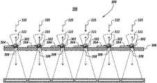
- FIG. 1includes a schematic functional block diagram of a scanning LiDAR system, according to some exemplary embodiments.
- FIGS. 2A and 2Binclude schematic functional diagrams illustrating portions of the scanning LiDAR system of FIG. 1 , according to some exemplary embodiments.
- FIG. 3includes a schematic functional block diagram of a scanning LiDAR system, in which horizontal and vertical scanning are performed, according to exemplary embodiments.
- FIGS. 4A and 4Binclude schematic diagrams illustrating portions of a scanning LiDAR system in which a coaxial configuration is implemented, according to some exemplary embodiments.
- FIGS. 5A and 5Binclude schematic diagrams illustrating portions of scanning LiDAR systems, in which a coaxial configuration is implemented, according to some exemplary embodiments.
- FIGS. 6A and 6Binclude schematic cross-sectional diagrams which illustrate two configurations of coaxial scanning LiDAR systems, in which discrete lasers and discrete detectors are used, according to some exemplary embodiments.
- FIG. 7includes a schematic perspective view illustrating a portion of a scanning LiDAR system, according to some exemplary embodiments.
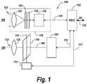
- FIG. 8includes four schematic views, labeled (A), (B), (C), and (D), of a unitary integrated optical element, according to some exemplary embodiments.
- FIG. 9includes a schematic perspective view of a LiDAR system with a plurality of systems illustrated in FIGS. 7 and 8 , according to some exemplary embodiments.
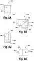
- FIG. 10includes a schematic perspective view illustrating a portion of a scanning LiDAR system, according to some exemplary embodiments.
- FIG. 11includes a schematic perspective view of a LiDAR system with a plurality of systems 900 illustrated in FIG. 10 , according to some exemplary embodiments.
- FIG. 12includes a schematic perspective view of an automobile equipped with one or more scanning LiDAR systems described herein in detail, according to some exemplary embodiments.
- FIG. 13includes a schematic top view of an automobile equipped with two scanning LiDAR systems, as described herein in detail, according to some exemplary embodiments.
- FIG. 1includes a schematic functional block diagram of a scanning LiDAR system 100 , according to exemplary embodiments.
- system 100includes a digital signal processor and controller (DSPC) 102 , which performs all of the control and signal processing required to carry out the LiDAR target object detection functionality of system 100 .
- An optical source 104such as a laser, operates under control of DSPC 102 via one or more control signals 116 to generate the one or more optical signals transmitted into a region 106 being analyzed.
- Optical source 104can include a single laser, or optical source 104 can include multiple lasers, which can be arranged in a one-dimensional or two-dimensional array.
- One or more optical signals 108 from source 104 impinge on scanning mirror 110which can be a microelectromechanical system (MEMS) scanning mirror.
- Scanning mirror 110is rotatable about an axis 114 by an actuator 112 , which operates under control of one or more control signals 117 provided by DSPC 102 to control the rotation angle of scanning mirror 110 , such that the one or more output optical signals are scanned at various angles into region 106 .
- the output optical signalspass through a lens or glass plate 122 , which generates one or more collimated optical signals 123 which are scanned across region 106 .
- Receive subsystem 118includes a lens 120 which receives and focuses light 125 returning from region 106 .
- mask 124is located at the focal plane of lens 120 , such that the returning light is focused at mask 124 .
- Light passing through mask 124impinges on optical detector or detector array 126 .
- Detector array 126converts the received optical signals to electrical signals, and a processor 128 generates digital signals based on the electrical signals and transmits the digital signals 130 to DSPC 102 for processing to develop target object identification, tracking and/or other operations. Reports of detections to one or more user interfaces or memory or other functions can be carried out via I/O port 132 .
- FIGS. 2A and 2Binclude schematic functional diagrams illustrating portions of scanning LiDAR system 100 of FIG. 1 , according to exemplary embodiments.
- FIGS. 2A and 2Billustrate scanning of the transmitted optical signals into region 106 and reception of returning optical signals for a first angular direction of scanning of scanning mirror 110 about axis 114 and a second opposite angular scanning direction of scanning mirror 110 about axis 114 , respectively.
- optical source 104can include one or more linear arrays of lasers disposed along an axis. That is, each linear array of lasers can include a plurality of lasers disposed along a vertical axis, i.e., a y-axis. In the exemplary embodiment illustrated in FIGS. 2A and 2B , two linear arrays are disposed along parallel axes in the y-axis direction. The axes can be displaced along a horizontal axis, i.e., an x-axis. Also, the two linear laser arrays can be displaced also in the vertical direction (y-axis) in order to generate different elevation angles.
- each of two linear arraysincludes 8 lasers disposed along the y-axis, for a total of 16 lasers in the two-dimensional array. It will be understood that any number of lasers can be used, in accordance with the present embodiments. For example, in some particular exemplary embodiments, two linear arrays of 11 lasers, i.e., a total of 22 lasers, are used.
- the optical output signals from the laser array in source 104are focused by a lens 111 onto MEMS scanning mirror 110 .
- the optical signalsare reflected from scanning mirror 110 through glass plate or lens 122 , which generates the substantially mutually parallel collimated optical output signals 123 .
- Controlled rotation of scanning mirror 110 via actuator 112 and DSPC 102scans the collimated optical output signals 123 over region 106 .
- Output signals or beams 123constitute a fan of beams 123 , where each beam is collimated.
- the fan anglecan be 15° to 22°.
- beams 123are substantially mutually parallel.
- Light 125 returning from region 106is received at lens 120 of receive subsystem 118 .
- Lens 120focuses the returning light 125 onto mask 124 , which is positioned in front of optical detector array 126 .
- detectorsare arranged to provide a focal plane detector.
- Detector array 126converts the received optical signals to electrical signals, and processor 128 generates digital signals based on the electrical signals and transmits the digital signals 130 to DSPC 102 for processing to develop target object identification, tracking and/or other operations. Reports of detections to one or more user interfaces or memory or other functions can be carried out via I/O port 132 .
- FIGS. 2A and 2Bin some particular exemplary embodiments, two arrays of 1 ⁇ 8 lasers are used to generate 16 individual laser beams, each beam with a nominal divergence of ⁇ 0.1°.
- the vertical divergence of the group of 8 beamsis nominally approximately 15°.
- Scanning mirror 110is controlled to scan across a nominal range of approximately 60°, i.e., ⁇ 30° from its centered position. These angular limits are illustrated in FIGS. 2A and 2B in the diagrams of the x-y plane.
- FIG. 2Aillustrates the case in which the output optical signals 123 are scanned in a first direction (to the right in FIG.
- FIG. 2Aillustrates the case in which the output signals 123 are scanned in a second direction (to the right in FIG. 2B ) via angular rotation of scanning mirror 110 in a second angular direction.
- the resulting returning optical signalsare scanned across the columns of the 32 ⁇ 8 detector array 126 illuminating pixels in the array in a predetermined order determined by the scanning of the output optical signals 123 into region 106 , as illustrated in the schematic illustrations of pixel illumination scanning 137 and 139 in FIGS. 2A and 2B , respectively.
- all of these parametersare exemplary nominal values. According to the present disclosure, any number of lasers can be used, having a group beam divergence of greater than or less than 15°, and the angular scanning limits can be greater than or less than ⁇ 30° from the centered position of scanning mirror 110 .
- FIG. 3includes a schematic functional block diagram of a scanning LiDAR system 100 A, in which horizontal and vertical scanning are performed, according to exemplary embodiments.
- elements that are substantially the same as those in FIGS. 1, 2A and 2Bare identified by the same reference numerals.
- actuator 112 Ain addition to initiating and controlling horizontal scanning of scanning mirror 110 A about vertical axis 114 , initiates and controls vertical scanning of scanning mirror 110 A about horizontal axis 114 A.
- mask 124is also moved vertically alternately up and down in synchronization with the vertical scanning of scanning mirror 110 A.
- Vertical movement of mask 124is initiated by a mechanical actuation device, such as a piezoelectric actuator 202 , in synchronization with scanning of scanning mirror 110 A, such that alignment of mask 124 with returning light 125 is maintained.
- This synchronizationis accomplished via interface 204 with DSPC 102 .
- FIGS. 4A and 4Binclude schematic diagrams illustrating portions of a scanning LiDAR system 200 in which a coaxial configuration is implemented, according to some exemplary embodiments.
- FIG. 4Aillustrates a single coaxial configuration
- FIG. 4Billustrates multiple coaxial configurations in parallel.
- a laser light source 304 integrated on or in a substrate 306generates an output beam of light.
- the output beamis reflected by a polarizing beam splitting cube 302 such that output signals 323 are transmitted into region 106 .
- Returning light signals 325 from region 106are transmitted through beam splitting cube 302 , through an opening 308 in substrate 306 .
- bandpass filter 305is characterized by a drift in its wavelength pass band which is dependent on temperature.
- Laser light source 304can also have a temperature-dependent drift in wavelength of its output.
- the temperature drift of laser light source 304 and that of bandpass filter 305are matched, such that temperature effects on operation of the overall system are substantially reduced.
- FIGS. 5A and 5Binclude schematic diagrams illustrating portions of scanning LiDAR systems 300 A and 300 B, respectively, in which a coaxial configuration is implemented, according to some exemplary embodiments.
- the primary difference between systems 300 A, 300 B of FIGS. 5A and 50Bis that, in system 300 A, mask 324 is under substrate 306 , and, in system 300 B, mask 324 is at the top side of substrate 306 .
- incoming light from polarizing beam splitting cube 302passes through slits, openings or apertures 342 in mask 324 and impinges on detector 326 .
- lens 322generates the substantially mutually parallel collimated optical output signals 323 A. Controlled rotation of the scanning mirror scans the substantially mutually parallel collimated optical output signals 323 A over the region being analyzed.
- polarizing beam splitting cube 302 in the embodiments described above in detail in connection with FIGS. 4A, 4B, 5A and 5Bneed not be a cube.
- polarizing beam splitting cube 302can be replaced with a polarizing beam splitting plate tilted at an appropriate angle with respect to the optical paths of the respective systems.
- FIGS. 6A and 6Binclude schematic cross-sectional diagrams which illustrate two configurations of coaxial scanning LiDAR systems 600 and 700 , respectively, in which discrete lasers and discrete detectors are used, according to some exemplary embodiments.
- a laser light source 604is integrated on or over a substrate 606 , with a layer of inert spacing material 605 , made of, for example, printed circuit board (PCB) material, epoxy, metal or similar material, mounted therebetween.
- Laser light source 604generates an output beam of light 607 , which impinges on a beam splitting cube 602 , such that output signals 623 are transmitted into region 106 .
- PCBprinted circuit board
- detector 626is a surface mount device mounted to the bottom surface of substrate 606 .
- laser light source 604is one of an array of laser light sources disposed in parallel along an axis directed substantially normal to the page of FIG. 6A .
- polarizing or non-polarizing beam splitting cube or plate 602can be a single long cube or plate, or multiple cubes or plates, extending along the same axis normal to the page.
- detector 626can be a single long detector or array of detectors, or multiple detectors or arrays of detectors, extending along the same axis normal to the page.
- beam splitting cube 702or polarizing beam splitting cube 702 , need not be a cube. It may be a beam splitting plate or polarizing beam splitting plate tilted at an appropriate angle with respect to the optical path(s).
- Light beams 725 from slit 742are detected by detector 726 , which is mounted to the top side or surface of second substrate 728 .
- First substrate 706 and second substrate 728are mechanically supported and properly located with respect to each other by a mounting/spacing support layer 709 .
- Mounting/spacing support layer 709can be made of, for example, a layer of inert spacing material, made of, for example, printed circuit board (PCB) material, epoxy, metal, or other similar material.
- the physical configuration of mounting/spacing support layer 709i.e., dimensions, location, etc., are selected to provide appropriate support and stability among components such as laser light source 704 , beam splitting cube 702 , first substrate 706 , second substrate 728 , mask 724 and slit 742 , such that the performance requirements of system 700 are met.
- laser light source 704is one of an array of laser light sources disposed in parallel along an axis directed substantially normal to the page of FIG. 6B .
- polarizing or non-polarizing beam splitting cube or plate 702can be a single long cube or plate, or multiple cubes or plates, extending along the same axis normal to the page.
- detector 726can be a single long detector or array of detectors, or multiple detectors or arrays of detectors, extending along the same axis normal to the page.
- FIG. 7includes a schematic perspective view illustrating a portion of a scanning LiDAR system 800 , according to some exemplary embodiments.
- system 800includes laser diode source 804 for emitting illuminating light.
- a fast axis collimating (FAC) lens 808receives the light from laser diode source 804 , collimates the light and passes it to polarizing beam splitting cube 806 .
- Illuminating light which passes through polarizing beam splitting cube 806may pass through an optional quarter wave plate 810 which converts linearly polarized light into circularly polarized light
- the illuminating light passing through polarizing beam splitting cube 806 and/or quarter wave plate 810is scanned into region 106 being monitored.
- slit aperture mask 812includes a glass substrate with an opaque coating 814 deposited on the glass. Opaque coating 814 is patterned to provide a slit opening or aperture through with returning light passes. This light is received by a photo detector or photo detector array 822 .
- optical componentsincluding laser diode 804 , FAC lens 808 , polarizing beam splitting cube 806 , quarter wave plate 810 , and slit aperture mask 812 are mounted or formed on a first substrate or printed circuit board (PCB) 820 .
- Detector 822is mounted or formed on a second substrate or PCB 818 .
- First and second PCBs 820 and 818are spatially supported and fixedly attached to each other and held stationary with respect to each other by a supporting frame element 816 .
- PCBs 820 , 818are held substantially perpendicular.
- optical componentssuch laser source 804 , FAC lens 808 , polarizing beam splitting cube 806 , quarter wave plate 810 and slit aperture mask 812 can be integrated in a single unitary optical element, which can be manufactured to very close tolerances, such that spatial relationships among the optical elements are precisely, accurately and permanently controlled, thus eliminating the need for active alignment.
- FIG. 8includes four schematic views, labeled (A), (B), (C), and (D), of a unitary integrated optical element 850 , according to some exemplary embodiments.
- unitary integrated optical element 850includes one-piece precision glass optics, which includes laser diode source 804 , FAC lens 808 , polarizing beam splitting cube 806 , slit aperture mask 812 , 814 and quarter wave plate 810 in a single precision optical element.
- laser diode sourceneed not be integrated in unitary integrated optical element 850 .
- laser diode sourceis a separate element, which can be formed on PCB 820 , or formed on a separate laser PCB, which is mounted on PCB 820 .
- slit, opening or aperture 817 formed in mask 814 in slit aperture mask 812is positioned precisely with respect to FAC lens 808 and polarizing beam splitting cube 806 portions of the single unitary optical element 850 .
- mask 814 including the patterned opaque coating providing slit, opening or aperture 817need not be a separate element 812 . Instead, coating 814 and slit, opening or aperture 817 can be formed directly on the surface of polarizing beam splitting cube 806 . In this alternative embodiment, referring to FIGS. 7 and 8 , slit aperture mask element 812 would be omitted, and coating 814 with slit, opening or aperture 817 would be formed directly on the surface of polarizing beam splitting cube 806 .
- FIG. 9includes a schematic perspective view of a LiDAR system 890 with a plurality of systems 800 illustrated in FIGS. 7 and 8 , according to some exemplary embodiments.
- each system 800includes the unitary one-piece integrated optic element 850 A, 850 B, 850 C mounted on first substrate or PCB 820 A, 820 B, 820 C.
- each integrated optic element 850 A, 850 B, 850 Cincludes a laser diode source 804 A, 804 B, 804 C; a FAC lens 808 A, 808 B, 808 C; a polarizing beam splitting cube 806 A, 806 B, 806 C; a slit aperture mask 812 A, 812 B, 812 C with a respective patterned mask 814 A, 814 B, 814 C; and an optional quarter wave plate 810 A, 810 B, 810 C.
- First substrates or PCBs 820 A, 820 B, 820 C and second substrate or PCB 818are spatially supported and fixedly attached to each other and held stationary with respect to each other by a respective supporting frame element 816 A, 816 B, 816 C.
- PCBs 820 A, 820 B, 820 Care held substantially perpendicular to second substrate or PCB 818 .
- FIG. 10includes a schematic perspective view illustrating a portion of another scanning LiDAR system 900 , according to some exemplary embodiments.
- System 900 of FIG. 10is different from system 800 of FIG. 7 in that, in system 900 of FIG. 10 , a single substrate or PCB 920 is used instead of a pair of substrates 818 , 820 held perpendicular to each other. This is accomplished in system 900 by the addition of a 45-degree prism 923 added at the optical slit or aperture of slit aperture mask 912 . Light passing through slit aperture mask 912 is directed down to the surface of substrate or PCB 920 , on which optical detector or array of detectors 922 is mounted.
- System 900includes laser diode source 904 mounted on or in laser PCB 905 , which is mounted on substrate or PCB 920 .
- a fast axis collimating (FAC) lens 908receives the light from laser diode source 904 , collimates the light and passes it to polarizing beam splitting cube 906 .
- Illuminating light which passes through polarizing beam splitting cube 806may pass through an optional quarter wave plate 910 which converts linearly polarized light into circularly polarized light
- the illuminating light passing through polarizing beam splitting cube 906 and/or quarter wave plate 910is scanned into region 106 being monitored. Light returning from region 106 is directed by polarizing beam splitting cube 906 through slit aperture mask 912 .
- slit aperture mask 912includes a glass substrate with an opaque coating 914 deposited on the glass. Opaque coating 914 is patterned to provide a slit opening or aperture 917 through with returning light passes. The light passing through slit opening or aperture 917 is reflected by 45-degree prism 923 toward substrate or PCB 920 . This light is received by photo detector or photo detector array 922 , which is mounted on substrate or PCB 920 .
- the optical elements of system 900can be integrated in a single unitary optical element 950 , which can be manufactured to very close tolerances, such that spatial relationships among the optical elements are precisely, accurately and permanently controlled, thus eliminating the need for active alignment.
- optical componentssuch as laser diode source 904 , FAC lens 908 , polarizing beam splitting cube 906 , quarter wave plate 910 , slit aperture mask 912 , and 45-degree prism 923 can be integrated in a single unitary optical element 950 .
- unitary integrated optical element 950includes one-piece precision glass optics, which includes laser diode source 904 , FAC lens 908 , polarizing beam splitting cube 906 , quarter wave plate 910 , slit aperture mask 912 , and 45-degree prism 923 in a single precision optical element. All of the elements are made to very tight tolerances to provide the desired device alignment. In particular, slit, opening or aperture 917 formed in mask 914 in slit aperture mask 912 is positioned precisely with respect to FAC lens 908 and polarizing beam splitting cube 906 portions of the single unitary optical element 950 .
- laser diode source 904need not be integrated in unitary integrated optical element 950 .
- laser diode source 904is a separate element, which can be formed on PCB 920 , or formed on laser PCB 905 , which is mounted on PCB 920 .
- mask 914 including the patterned opaque coating providing slit, opening or aperture 917need not be a separate element 912 . Instead, coating 914 and slit, opening or aperture 917 can be formed directly on the surface of polarizing beam splitting cube 906 .
- slit aperture mask element 912would be omitted, and coating 914 with slit, opening or aperture 917 would be formed directly on the surface of polarizing beam splitting cube 906 .
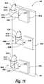
- FIG. 11includes a schematic perspective view of a LiDAR system 990 with a plurality of systems 900 illustrated in FIG. 10 , according to some exemplary embodiments.
- each system 900includes the unitary one-piece integrated optic element 950 A, 950 B, 950 C mounted on substrate or PCB 920 .
- each integrated optic element 950 A, 950 B, 950 Cincludes a laser diode source 904 A, 904 B, 904 C on a respective laser PCB 905 A, 905 B, 905 C; a FAC lens 908 A, 908 B, 908 C; a polarizing beam splitting cube 906 A, 906 B, 906 C; a slit aperture mask 912 A, 912 B, 912 C with a respective patterned mask 914 A, 914 B, 914 C; an optional quarter wave plate 910 A, 910 B, 910 C; and a 45-degree prism 912 A, 923 B, 923 C.
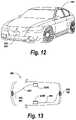
- FIG. 12includes a schematic perspective view of an automobile 500 , equipped with one or more scanning LiDAR systems 800 , 900 , described herein in detail, according to exemplary embodiments.
- scanning LiDAR system 800 , 900is illustrated as being mounted on or in the front section of automobile 500 .
- one or more scanning LiDAR systems 800 , 900can be mounted at various locations on automobile 500 .
- LiDAR system 800 , 900can be replaced with any of the LiDAR systems described herein. That is, the description of FIG. 12 is applicable to an automobile equipped with any of the embodiments described herein.
- FIG. 13includes a schematic top view of automobile 500 equipped with two scanning LiDAR systems 800 , 900 , as described above in detail, according to exemplary embodiments.
- a first LiDAR system 800 , 900is connected via a bus 560 , which in some embodiments can be a standard automotive controller area network (CAN) bus, to a first CAN bus electronic control unit (ECU) 558 A.
- CANstandard automotive controller area network
- ECUelectronic control unit
- a second LiDAR scanning system 800 , 900is connected via CAN bus 560 to a second CAN bus electronic control unit (ECU) 558 B. Detections generated by the LiDAR processing described herein in detail in LiDAR system 800 , 900 can be reported to ECU 558 B, which processes the detections and can provide detection alerts via CAN bus 560 . It should be noted that this configuration is exemplary only, and that many other automobile LiDAR configurations within automobile 500 can be implemented. For example, a single ECU can be used instead of multiple ECUs. Also, the separate ECUs can be omitted altogether. Also, it will be understood that LiDAR system 800 , 900 can be replaced with any of the LiDAR systems described herein. That is, the description of FIG. 17 is applicable to an automobile equipped with any of the embodiments described herein.
- the present disclosuredescribes one or more scanning LiDAR systems installed in an automobile. It will be understood that the embodiments of scanning LiDAR systems of the disclosure are applicable to any kind of vehicle, e.g., bus, train, etc. Also, the scanning LiDAR systems of the present disclosure need not be associated with any kind of vehicle.
Landscapes
- Engineering & Computer Science (AREA)
- Physics & Mathematics (AREA)
- General Physics & Mathematics (AREA)
- Computer Networks & Wireless Communication (AREA)
- Radar, Positioning & Navigation (AREA)
- Remote Sensing (AREA)
- Optics & Photonics (AREA)
- Electromagnetism (AREA)
- Optical Radar Systems And Details Thereof (AREA)
Abstract
Description
Claims (17)
Priority Applications (3)
| Application Number | Priority Date | Filing Date | Title |
|---|---|---|---|
| US16/511,432US11474218B2 (en) | 2019-07-15 | 2019-07-15 | Scanning LiDAR system and method with unitary optical element |
| US16/542,529US11579257B2 (en) | 2019-07-15 | 2019-08-16 | Scanning LiDAR system and method with unitary optical element |
| PCT/US2020/039760WO2021011172A1 (en) | 2019-07-15 | 2020-06-26 | Scanning lidar apparatus with unitary optical element |
Applications Claiming Priority (1)
| Application Number | Priority Date | Filing Date | Title |
|---|---|---|---|
| US16/511,432US11474218B2 (en) | 2019-07-15 | 2019-07-15 | Scanning LiDAR system and method with unitary optical element |
Related Child Applications (1)
| Application Number | Title | Priority Date | Filing Date |
|---|---|---|---|
| US16/542,529Continuation-In-PartUS11579257B2 (en) | 2019-07-15 | 2019-08-16 | Scanning LiDAR system and method with unitary optical element |
Publications (2)
| Publication Number | Publication Date |
|---|---|
| US20210018602A1 US20210018602A1 (en) | 2021-01-21 |
| US11474218B2true US11474218B2 (en) | 2022-10-18 |
Family
ID=74343834
Family Applications (1)
| Application Number | Title | Priority Date | Filing Date |
|---|---|---|---|
| US16/511,432Active2041-05-01US11474218B2 (en) | 2019-07-15 | 2019-07-15 | Scanning LiDAR system and method with unitary optical element |
Country Status (1)
| Country | Link |
|---|---|
| US (1) | US11474218B2 (en) |
Families Citing this family (11)
| Publication number | Priority date | Publication date | Assignee | Title |
|---|---|---|---|---|
| US11460550B2 (en) | 2017-09-19 | 2022-10-04 | Veoneer Us, Llc | Direct detection LiDAR system and method with synthetic doppler processing |
| US11194022B2 (en) | 2017-09-29 | 2021-12-07 | Veoneer Us, Inc. | Detection system with reflection member and offset detection array |
| US11585901B2 (en) | 2017-11-15 | 2023-02-21 | Veoneer Us, Llc | Scanning lidar system and method with spatial filtering for reduction of ambient light |
| US11474218B2 (en) | 2019-07-15 | 2022-10-18 | Veoneer Us, Llc | Scanning LiDAR system and method with unitary optical element |
| US11579257B2 (en)* | 2019-07-15 | 2023-02-14 | Veoneer Us, Llc | Scanning LiDAR system and method with unitary optical element |
| WO2021029969A1 (en)* | 2019-08-13 | 2021-02-18 | Apple Inc. | Focal plane optical conditioning for integrated photonics |
| US12044800B2 (en) | 2021-01-14 | 2024-07-23 | Magna Electronics, Llc | Scanning LiDAR system and method with compensation for transmit laser pulse effects |
| US11732858B2 (en) | 2021-06-18 | 2023-08-22 | Veoneer Us, Llc | Headlight illumination system using optical element |
| US12228653B2 (en) | 2022-10-07 | 2025-02-18 | Magna Electronics, Llc | Integrating a sensing system into headlight optics |
| US12092278B2 (en) | 2022-10-07 | 2024-09-17 | Magna Electronics, Llc | Generating a spotlight |
| US12202396B1 (en) | 2023-12-19 | 2025-01-21 | Magna Electronics, Llc | Line-scan-gated imaging for LiDAR headlight |
Citations (161)
| Publication number | Priority date | Publication date | Assignee | Title |
|---|---|---|---|---|
| US3712985A (en) | 1970-09-17 | 1973-01-23 | Us Navy | Optical spatial filter for modification of received energy vs range |
| US3898656A (en) | 1967-06-27 | 1975-08-05 | Us Navy | Radar data converter and display system |
| US4125864A (en) | 1976-03-03 | 1978-11-14 | Crosfield Electronics Limited | Beam splitter |
| US4184154A (en) | 1976-06-21 | 1980-01-15 | International Telephone And Telegraph Corporation | Range and angle determining Doppler radar |
| US4362361A (en) | 1980-09-15 | 1982-12-07 | The United States Of America As Represented By The Administrator Of The National Aeronautics And Space Administration | Collimated beam manifold with the number of output beams variable at a given output angle |
| US4439766A (en) | 1981-05-22 | 1984-03-27 | The United States Of America As Represented By The Administrator Of The National Aeronautics & Space Administration | Doppler radar having phase modulation of both transmitted and reflected return signals |
| EP0112188B1 (en) | 1982-12-21 | 1987-06-16 | Crosfield Electronics Limited | Light beam-splitter |
| US4765715A (en) | 1983-07-13 | 1988-08-23 | Hoya Corporation | Beam splitter having a partial semitransparent layer assigned to a plurality of outgoing light beams |
| US4957362A (en) | 1989-09-08 | 1990-09-18 | Environmental Research Institute Of Michigan | Method and apparatus for electro-optical phase detection |
| US5200606A (en) | 1991-07-02 | 1993-04-06 | Ltv Missiles And Electronics Group | Laser radar scanning system |
| US5210586A (en) | 1990-06-27 | 1993-05-11 | Siemens Aktiengesellschaft | Arrangement for recognizing obstacles for pilots of low-flying aircraft |
| US5274379A (en) | 1991-11-08 | 1993-12-28 | Her Majesty The Queen As Represented By The Minister Of National Defence Of Her Majesty's Canadian Government | Optical identification friend-or-foe |
| EP0578129A2 (en) | 1992-07-10 | 1994-01-12 | BODENSEEWERK GERÄTETECHNIK GmbH | Imaging sensor unit |
| WO1994019705A1 (en) | 1993-02-16 | 1994-09-01 | Silicon Heights Ltd. | A vehicle anti-collision device |
| US5428215A (en) | 1994-05-27 | 1995-06-27 | Her Majesty The Queen In Right Of Canada, As Represented By Minister Of National Defence Of Her Majesty's Canadian Government | Digital high angular resolution laser irradiation detector (HARLID) |
| US5604695A (en) | 1995-06-05 | 1997-02-18 | Her Majesty The Queen, As Represented By The Minister Of National Defence Of Her Majesty's Canadian Government | Analog high resolution laser irradiation detector (HARLID) |
| US5793491A (en) | 1992-12-30 | 1998-08-11 | Schwartz Electro-Optics, Inc. | Intelligent vehicle highway system multi-lane sensor and method |
| US5889490A (en) | 1996-08-05 | 1999-03-30 | Wachter; Eric A. | Method and apparatus for improved ranging |
| DE19757840C1 (en) | 1997-12-24 | 1999-09-30 | Johann F Hipp | Optical object detection and range measuring device for autonomous vehicle |
| US5966226A (en) | 1996-10-11 | 1999-10-12 | Oerlikon-Contraves Ag | Combat communication system |
| US6078395A (en) | 1997-09-19 | 2000-06-20 | Commissariat A L'energie Atomique | Tunable Fabry-Perot interferometer with floating electrode on one mirror and control electrode pair on opposing mirror |
| US6122222A (en) | 1995-03-02 | 2000-09-19 | Acuson Corporation | Ultrasonic transmit and receive system |
| US6292285B1 (en) | 1999-12-20 | 2001-09-18 | Xerox Corporation | Single rotating polygon mirror with v-shaped facets for a multiple beam ROS |
| US20010052872A1 (en) | 2000-02-08 | 2001-12-20 | Cornelius Hahlweg | Radar system for determining optical visual range |
| US6384770B1 (en) | 1992-06-05 | 2002-05-07 | Thomson-Csf | Linearizing device for a frequency-modulation ramp and its application to a radio altimeter |
| US20030043363A1 (en) | 2001-09-04 | 2003-03-06 | Jamieson James R. | Combined loas and lidar system |
| US6559932B1 (en) | 2001-10-30 | 2003-05-06 | Raytheon Company | Synthetic aperture ladar system using incoherent laser pulses |
| US20040028418A1 (en) | 2001-09-26 | 2004-02-12 | Arkady Kaplan | Electro-optical integrated transmitter chip for arbitrary quadrature modulation of optical signals |
| US20040031906A1 (en) | 2000-04-26 | 2004-02-19 | Glecker Anthony D | Very fast time resolved imaging in multiparameter measurement space |
| US20040135992A1 (en) | 2002-11-26 | 2004-07-15 | Munro James F. | Apparatus for high accuracy distance and velocity measurement and methods thereof |
| US20040155249A1 (en) | 2003-01-28 | 2004-08-12 | Sony Corporation | Optical semiconductor apparatus |
| US20050219506A1 (en) | 2004-03-31 | 2005-10-06 | Keiko Okuda | Object recognition device for vehicle |
| DE102004033944A1 (en) | 2004-07-14 | 2006-02-02 | Conti Temic Microelectronic Gmbh | Operating condition examining device for e.g. optical sensor arrangement, has examination control unit with timer that is programmed such that characteristic reflection of light pulse for preset assembling position in vehicle is evaluated |
| US20060221250A1 (en) | 2004-01-28 | 2006-10-05 | Canesta, Inc. | Method and system to increase X-Y resolution in a depth (Z) camera using red, blue, green (RGB) sensing |
| US20060232052A1 (en) | 1995-06-07 | 2006-10-19 | Automotive Technologies International, Inc. | Vehicular Bus Including Crash Sensor or Occupant Protection System Control Module |
| US20060239312A1 (en) | 2005-04-23 | 2006-10-26 | Telaris Inc. | Semiconductor Lasers in Optical Phase-Locked Loops |
| US20070140613A1 (en) | 2003-07-02 | 2007-06-21 | Celight, Inc. | Integrated coherent optical detector |
| US20070181810A1 (en) | 2006-02-06 | 2007-08-09 | Tan Michael R T | Vertical cavity surface emitting laser (VCSEL) array laser scanner |
| US20070211786A1 (en) | 1998-02-12 | 2007-09-13 | Steve Shattil | Multicarrier Sub-Layer for Direct Sequence Channel and Multiple-Access Coding |
| US20070219720A1 (en) | 2006-03-16 | 2007-09-20 | The Gray Insurance Company | Navigation and control system for autonomous vehicles |
| WO2008008970A2 (en) | 2006-07-13 | 2008-01-17 | Velodyne Acoustics, Inc | High definition lidar system |
| US20080088499A1 (en) | 2006-05-24 | 2008-04-17 | Bonthron Andrew J | Methods and apparatus for hyperview automotive radar |
| US20080095121A1 (en) | 2002-05-14 | 2008-04-24 | Shattil Steve J | Carrier interferometry networks |
| US20080100510A1 (en) | 2006-10-27 | 2008-05-01 | Bonthron Andrew J | Method and apparatus for microwave and millimeter-wave imaging |
| DE102006031114B4 (en) | 2006-06-29 | 2008-07-03 | Kst Gmbh Kamera & System Technik | 3D combination meter from digital camera and laser scanner |
| US20080219584A1 (en) | 2007-03-06 | 2008-09-11 | Department Of The Navy | Image enhancer for detecting and identifying objects in turbid media |
| US20080246944A1 (en) | 2007-04-05 | 2008-10-09 | Brian Redman | Photon counting, chirped AM LADAR system and related methods |
| US7440084B2 (en) | 2004-12-16 | 2008-10-21 | Arete' Associates | Micromechanical and related lidar apparatus and method, and fast light-routing components |
| US20090002680A1 (en) | 2007-06-26 | 2009-01-01 | William Charles Ruff | Chirped amplitude modulation ladar |
| US20090010644A1 (en) | 2002-02-01 | 2009-01-08 | Cubic Corporation | Integrated optical communication and range finding system and applications thereof |
| US20090190007A1 (en) | 2008-01-30 | 2009-07-30 | Mesa Imaging Ag | Adaptive Neighborhood Filtering (ANF) System and Method for 3D Time of Flight Cameras |
| US20090251361A1 (en) | 2005-03-29 | 2009-10-08 | Beasley Patrick D L | Coherent Frequency Modulated Continuous Wave Radar |
| US20100027602A1 (en) | 2008-07-31 | 2010-02-04 | United States Of America As Represented By The Administrator Of The National Aeronautics And Spac | Time delay and distance measurement |
| DE102008045387A1 (en) | 2008-09-02 | 2010-03-04 | Carl Zeiss Ag | Apparatus and method for measuring a surface |
| US20100128109A1 (en) | 2008-11-25 | 2010-05-27 | Banks Paul S | Systems And Methods Of High Resolution Three-Dimensional Imaging |
| US20100157280A1 (en) | 2008-12-19 | 2010-06-24 | Ambercore Software Inc. | Method and system for aligning a line scan camera with a lidar scanner for real time data fusion in three dimensions |
| US20100182874A1 (en) | 2007-06-28 | 2010-07-22 | Michael Frank | Method and device for detection of surroundings |
| US20120075422A1 (en) | 2010-09-24 | 2012-03-29 | PixArt Imaging Incorporation, R.O.C. | 3d information generator for use in interactive interface and method for 3d information generation |
| US20120182540A1 (en) | 2009-11-24 | 2012-07-19 | Hamamatsu Photonics K.K. | Range sensor and range image sensor |
| US20120206712A1 (en) | 2011-02-14 | 2012-08-16 | Optical Air Data Systems, Llc | Laser Wind Velocimeter With Multiple Radiation Sources |
| US20120236379A1 (en) | 2010-08-23 | 2012-09-20 | Lighttime, Llc | Ladar using mems scanning |
| US20120310516A1 (en) | 2011-06-01 | 2012-12-06 | GM Global Technology Operations LLC | System and method for sensor based environmental model construction |
| US20120310519A1 (en) | 2004-12-15 | 2012-12-06 | Magna Donnelly Engineering Gmbh | Accessory mounting system for a vehicle |
| US20130088726A1 (en) | 2011-10-07 | 2013-04-11 | Vivek K. Goyal | Method and Apparatus to Determine Depth Information For A Scene of Interest |
| US20130093584A1 (en) | 2011-10-14 | 2013-04-18 | Continental Automotive Systems, Inc. | Integrated Rear Camera Display |
| US20130120760A1 (en) | 2011-11-11 | 2013-05-16 | Daniel H. Raguin | Ambient light rejection for non-imaging contact sensors |
| US20130166113A1 (en) | 2011-12-23 | 2013-06-27 | Optical Air Data Systems, Llc | LDV System for Measuring Wind at High Altitude |
| US20130207970A1 (en) | 2012-02-15 | 2013-08-15 | Primesense Ltd. | Scanning depth engine |
| US20130222786A1 (en) | 2010-08-09 | 2013-08-29 | Steen Hanson | Vector velocimeter |
| US8629975B1 (en) | 2010-08-18 | 2014-01-14 | The United States Of America As Represented By The Secretary Of The Air Force | Apparatus and method for a multiple aperture coherent ladar |
| US20140036252A1 (en) | 2012-08-03 | 2014-02-06 | U.S.A. As Represented By The Administrator Of The National Aeronautics And Space Administration | Coherent Doppler Lidar for Measuring Altitude, Ground Velocity, and Air Velocity of Aircraft and Spaceborne Vehicles |
| EP2696166A2 (en) | 2012-08-06 | 2014-02-12 | Ricoh Company, Ltd. | Optical measurement device and vehicle |
| US20140049609A1 (en) | 2012-08-14 | 2014-02-20 | Microsoft Corporation | Wide angle depth detection |
| US8742325B1 (en) | 2013-07-31 | 2014-06-03 | Google Inc. | Photodetector array on curved substrate |
| US20140152975A1 (en) | 2012-12-04 | 2014-06-05 | Texas Instruments Incorporated | Method for dynamically adjusting the operating parameters of a tof camera according to vehicle speed |
| US20140168631A1 (en) | 2012-12-18 | 2014-06-19 | Pouch Holdings LLC | Multi-clad Fiber Based Optical Apparatus and Methods for Light Detection and Ranging Sensors |
| US20140233942A1 (en) | 2012-02-16 | 2014-08-21 | Nucrypt Llc | System and method for measuring the phase of a modulated optical signal |
| US8836922B1 (en) | 2013-08-20 | 2014-09-16 | Google Inc. | Devices and methods for a rotating LIDAR platform with a shared transmit/receive path |
| US20140313519A1 (en) | 2013-03-15 | 2014-10-23 | Primesense Ltd. | Depth scanning with multiple emitters |
| US20150009485A1 (en) | 2013-07-02 | 2015-01-08 | Electronics And Telecommunications Research Institute | Laser radar system |
| EP2824418A1 (en) | 2013-07-09 | 2015-01-14 | XenomatiX BVBA | Surround sensing system |
| WO2015014556A2 (en) | 2013-07-31 | 2015-02-05 | Valeo Schalter Und Sensoren Gmbh | Scanning optoelectronic detection device and motor vehicle having such a detection device |
| US9063549B1 (en) | 2013-03-06 | 2015-06-23 | Google Inc. | Light detection and ranging device with oscillating mirror driven by magnetically interactive coil |
| US9086273B1 (en) | 2013-03-08 | 2015-07-21 | Google Inc. | Microrod compression of laser beam in combination with transmit lens |
| US9097646B1 (en) | 2010-06-23 | 2015-08-04 | United States Of America As Represented By The Administrator Of The National Aeronautics And Space Administration | Modulated sine waves for differential absorption measurements using a CW laser system |
| US20150234308A1 (en) | 2011-08-03 | 2015-08-20 | Samsung Electronics Co., Ltd. | Light scanning unit and image forming apparatus employing the same |
| US20150260843A1 (en) | 2014-03-13 | 2015-09-17 | Pulsedlight, Inc. | Lidar optical scanner system |
| US20150301162A1 (en) | 2013-04-23 | 2015-10-22 | Tae Min Kim | Distance measuring method and equipment using optical signal |
| US20150371074A1 (en) | 2014-06-23 | 2015-12-24 | Shanghai Oxi Technology Co., Ltd. | Integrated optical sensor and methods for manufacturing and using the same |
| US20150378011A1 (en) | 2014-06-27 | 2015-12-31 | Hrl Laboratories Llc | Compressive scanning lidar |
| AT509180B1 (en) | 2009-11-19 | 2016-01-15 | Riegl Laser Measurement Sys | OPTOELECTRONIC MEASURING SYSTEM |
| US20160047903A1 (en) | 2014-08-15 | 2016-02-18 | US LADAR, Inc. | Ladar Point Cloud Compression |
| US9285477B1 (en) | 2013-01-25 | 2016-03-15 | Apple Inc. | 3D depth point cloud from timing flight of 2D scanned light beam pulses |
| DE102014218957A1 (en) | 2014-09-19 | 2016-03-24 | Automotive Lighting Reutlingen Gmbh | For the periodic deflection of a laser beam directed Lichtumlenkelement |
| WO2016072483A1 (en) | 2014-11-07 | 2016-05-12 | 大日本印刷株式会社 | Optical apparatus |
| US20160138944A1 (en) | 2014-11-18 | 2016-05-19 | Blackberry Limited | Proximity Sensor |
| US20160178749A1 (en) | 2014-12-22 | 2016-06-23 | Google Inc | Image sensor and light source driver integrated in a same semiconductor package |
| WO2016097409A2 (en) | 2014-12-19 | 2016-06-23 | Windar Photonic A/S | Lidar based on mems |
| US20160200161A1 (en) | 2015-01-13 | 2016-07-14 | Xenomatix Nv | Surround sensing system with telecentric optics |
| US20160245902A1 (en) | 2015-02-25 | 2016-08-25 | Abbie T. Watnik | Real-time processing and adaptable illumination lidar camera using a spatial light modulator |
| US20160280229A1 (en) | 2013-12-19 | 2016-09-29 | Ryosuke Kasahara | Object detection apparatus, moving body device control system and program thereof |
| US20160291160A1 (en) | 2015-03-31 | 2016-10-06 | Faro Technologies, Inc. | Mobile three-dimensional measuring instrument |
| US20160357187A1 (en) | 2015-06-05 | 2016-12-08 | Arafat M.A. ANSARI | Smart vehicle |
| US20160363669A1 (en) | 2015-06-12 | 2016-12-15 | Shanghai Jadic Optoelectronics Technology Co., Ltd. | Lidar imaging system |
| WO2016204139A1 (en) | 2015-06-16 | 2016-12-22 | 三菱電機株式会社 | Headlight device and lighting device |
| US20160380488A1 (en) | 2015-06-23 | 2016-12-29 | Qualcomm Incorporated | Systems, methods and apparatuses for guidance and alignment in electric vehicles wireless inductive charging systems |
| US20170023678A1 (en) | 2015-07-21 | 2017-01-26 | Robert Bosch Gmbh | Sensor system for a vehicle for detecting bridges or tunnel entrances |
| DE102015217908A1 (en) | 2015-09-18 | 2017-03-23 | Robert Bosch Gmbh | lidar |
| US20170090013A1 (en) | 2015-09-30 | 2017-03-30 | Autoliv Asp, Inc. | Apparatus and method for attenuating close-range radar signals in an automotive radar sensor |
| US9618742B1 (en) | 2013-03-08 | 2017-04-11 | Google Inc. | Rotatable mirror assemblies |
| US20170102457A1 (en) | 2014-05-30 | 2017-04-13 | Texas Tech University System | Hybrid fmcw-intererometry radar for positioning and monitoring and methods of using same |
| US20170199273A1 (en) | 2016-01-08 | 2017-07-13 | Fujitsu Limited | Apparatus, method for laser distance measurement, and non-transitory computer-readable storage medium |
| US20170219696A1 (en) | 2016-02-03 | 2017-08-03 | Konica Minolta, Inc. | Optical scanning type object detection device |
| US9753351B2 (en) | 2014-06-30 | 2017-09-05 | Quanergy Systems, Inc. | Planar beam forming and steering optical phased array chip and method of using same |
| US20170270381A1 (en) | 2014-11-26 | 2017-09-21 | Ricoh Company, Ltd. | Imaging device, object detector and mobile device control system |
| US20170269215A1 (en) | 2016-03-19 | 2017-09-21 | Velodyne Lidar, Inc. | Integrated Illumination And Detection For LIDAR Based 3-D Imaging |
| US20170285346A1 (en) | 2016-03-30 | 2017-10-05 | Coretronic Corporation | Optical waveguide device and head-mounted display apparatus using the same |
| US20170307737A1 (en) | 2014-10-09 | 2017-10-26 | Konica Minolta, Inc. | Scanning Optical System And Light Projection And Reception Device |
| US20170307736A1 (en) | 2016-04-22 | 2017-10-26 | OPSYS Tech Ltd. | Multi-Wavelength LIDAR System |
| US20170310948A1 (en) | 2016-04-26 | 2017-10-26 | Cepton Technologies, Inc. | Scanning Illuminated Three-Dimensional Imaging Systems |
| US20170329010A1 (en) | 2016-05-10 | 2017-11-16 | Texas Instruments Incorporated | Methods and apparatus for lidar operation with pulse position modulation |
| US20170329011A1 (en) | 2016-05-10 | 2017-11-16 | Texas Instruments Incorporated | Methods and apparatus for lidar operation with narrowband intensity modulation |
| US9869754B1 (en) | 2017-03-22 | 2018-01-16 | Luminar Technologies, Inc. | Scan patterns for lidar systems |
| US20180052378A1 (en) | 2016-08-17 | 2018-02-22 | Samsung Electronics Co., Ltd. | Optical phased array (opa) |
| US20180113193A1 (en) | 2016-10-24 | 2018-04-26 | Infineon Technologies Ag | Radar transceiver with phase noise cancellation |
| US20180128903A1 (en) | 2016-11-10 | 2018-05-10 | Lite-On Electronics (Guangzhou) Limited | Optical device |
| US20180136328A1 (en) | 2015-05-20 | 2018-05-17 | Autoliv Development Ab | An fmcw vehicle radar system |
| US20180143309A1 (en) | 2015-03-27 | 2018-05-24 | Waymo Llc | Methods and Systems for LIDAR Optics Alignment |
| US20180180718A1 (en) | 2016-12-28 | 2018-06-28 | Hon Hai Precision Industry Co., Ltd. | Distance detecting device using laser beam |
| US20180224529A1 (en) | 2017-02-06 | 2018-08-09 | Robo-Team Home Ltd. | Light detection and ranging device |
| US20180241477A1 (en) | 2017-02-17 | 2018-08-23 | Institut National D'optique | Phase-error correction in a synthetic aperture imaging system with local oscillator time delay adjustment |
| US10088557B2 (en) | 2015-03-20 | 2018-10-02 | MSOTEK Co., Ltd | LIDAR apparatus |
| US20180286909A1 (en)* | 2017-03-28 | 2018-10-04 | Luminar Technologies, Inc. | Optical detector having a bandpass filter in a lidar system |
| US20180284282A1 (en) | 2017-03-29 | 2018-10-04 | SZ DJI Technology Co., Ltd. | Lidar sensor system with small form factor |
| US20180284237A1 (en) | 2017-03-30 | 2018-10-04 | Luminar Technologies, Inc. | Non-Uniform Beam Power Distribution for a Laser Operating in a Vehicle |
| US20180284286A1 (en) | 2017-03-31 | 2018-10-04 | Luminar Technologies, Inc. | Multi-eye lidar system |
| US20180306913A1 (en) | 2015-10-16 | 2018-10-25 | Oliver Mark Bartels | Radio-based position determination with high-precision delay in the transponder |
| US20180341009A1 (en) | 2016-06-23 | 2018-11-29 | Apple Inc. | Multi-range time of flight sensing |
| US20180364334A1 (en) | 2017-06-19 | 2018-12-20 | Hesai Photonics Technology Co., Ltd. | Lidar system and method |
| US20180372870A1 (en) | 2016-05-24 | 2018-12-27 | Veoneer Us, Inc. | Direct detection lidar system and method with step frequency modulation (fm) pulse-burst envelope modulation transmission and quadrature demodulation |
| US20190018143A1 (en) | 2011-06-30 | 2019-01-17 | The Regents Of The University Of Colorado, A Body Corporate | Remote measurement of shallow depths in semi-transparent media |
| WO2019050643A1 (en) | 2017-09-05 | 2019-03-14 | Waymo Llc | Shared waveguide for a lidar transmitter and receiver |
| EP3457080A1 (en) | 2017-09-13 | 2019-03-20 | Topcon Corporation | Surveying instrument |
| US20190101644A1 (en) | 2017-09-29 | 2019-04-04 | Veoneer Us, Inc. | Multifunction vehicle detection system |
| US20190129009A1 (en) | 2017-11-01 | 2019-05-02 | Luminar Technologies, Inc. | Detection of crosstalk and jamming pulses with lidar system |
| US20190139951A1 (en) | 2014-08-06 | 2019-05-09 | Pixart Imaging Inc. | Image module package |
| US20190146060A1 (en) | 2017-11-10 | 2019-05-16 | Shenzhen Suteng JuChuang Technologies Ltd. Co. | Lidar devices |
| WO2019099166A1 (en) | 2017-11-15 | 2019-05-23 | Veoneer Us, Inc. | Scanning lidar system and method with spatial filtering for reduction of ambient light |
| US20190195990A1 (en) | 2017-12-22 | 2019-06-27 | Waymo Llc | Systems and Methods for Adaptive Range Coverage using LIDAR |
| US20190235064A1 (en) | 2017-06-09 | 2019-08-01 | Waymo Llc | LIDAR Optics Alignment Systems and Methods |
| US10408924B2 (en) | 2016-03-08 | 2019-09-10 | Electronics And Telecommunications Research Institute | Optical receiver and laser radar with scan operation |
| US10416292B2 (en) | 2016-05-24 | 2019-09-17 | Veoneer Us, Inc. | Direct detection LiDAR system and method with frequency modulation (FM) transmitter and quadrature receiver |
| US10473943B1 (en) | 2016-11-09 | 2019-11-12 | ColdQuanta, Inc. | Forming beamformer having stacked monolithic beamsplitters |
| EP3147685B1 (en) | 2015-09-22 | 2020-01-01 | Veoneer Sweden AB | A vehicle synthetic aperture radar system |
| US20200081129A1 (en) | 2018-09-10 | 2020-03-12 | Veoneer Us, Inc. | Detection system for a vehicle |
| US20200088847A1 (en) | 2018-09-14 | 2020-03-19 | Veoneer Us, Inc. | Scanning assembly for a detection system |
| US20200249354A1 (en) | 2017-09-26 | 2020-08-06 | Innoviz Technologies Ltd | Binning and non-binning combination |
| US10775508B1 (en) | 2016-08-19 | 2020-09-15 | Apple Inc. | Remote sensing device |
| US20200341121A1 (en) | 2019-04-25 | 2020-10-29 | Hyundai Motor Company | Lidar-integrated lamp device for vehicle |
| US20200341120A1 (en) | 2019-04-25 | 2020-10-29 | Hyundai Motor Company | Lidar integrated lamp apparatus of vehicle |
| US20210018602A1 (en) | 2019-07-15 | 2021-01-21 | Veoneer Us, Inc. | Scanning lidar system and method with unitary optical element |
- 2019
- 2019-07-15USUS16/511,432patent/US11474218B2/enactiveActive
Patent Citations (218)
| Publication number | Priority date | Publication date | Assignee | Title |
|---|---|---|---|---|
| US3898656A (en) | 1967-06-27 | 1975-08-05 | Us Navy | Radar data converter and display system |
| US3712985A (en) | 1970-09-17 | 1973-01-23 | Us Navy | Optical spatial filter for modification of received energy vs range |
| US4125864A (en) | 1976-03-03 | 1978-11-14 | Crosfield Electronics Limited | Beam splitter |
| US4184154A (en) | 1976-06-21 | 1980-01-15 | International Telephone And Telegraph Corporation | Range and angle determining Doppler radar |
| US4362361A (en) | 1980-09-15 | 1982-12-07 | The United States Of America As Represented By The Administrator Of The National Aeronautics And Space Administration | Collimated beam manifold with the number of output beams variable at a given output angle |
| US4439766A (en) | 1981-05-22 | 1984-03-27 | The United States Of America As Represented By The Administrator Of The National Aeronautics & Space Administration | Doppler radar having phase modulation of both transmitted and reflected return signals |
| EP0112188B1 (en) | 1982-12-21 | 1987-06-16 | Crosfield Electronics Limited | Light beam-splitter |
| US4765715A (en) | 1983-07-13 | 1988-08-23 | Hoya Corporation | Beam splitter having a partial semitransparent layer assigned to a plurality of outgoing light beams |
| US4957362A (en) | 1989-09-08 | 1990-09-18 | Environmental Research Institute Of Michigan | Method and apparatus for electro-optical phase detection |
| US5210586A (en) | 1990-06-27 | 1993-05-11 | Siemens Aktiengesellschaft | Arrangement for recognizing obstacles for pilots of low-flying aircraft |
| US5200606A (en) | 1991-07-02 | 1993-04-06 | Ltv Missiles And Electronics Group | Laser radar scanning system |
| US5274379A (en) | 1991-11-08 | 1993-12-28 | Her Majesty The Queen As Represented By The Minister Of National Defence Of Her Majesty's Canadian Government | Optical identification friend-or-foe |
| US6384770B1 (en) | 1992-06-05 | 2002-05-07 | Thomson-Csf | Linearizing device for a frequency-modulation ramp and its application to a radio altimeter |
| EP0578129A2 (en) | 1992-07-10 | 1994-01-12 | BODENSEEWERK GERÄTETECHNIK GmbH | Imaging sensor unit |
| US5793491A (en) | 1992-12-30 | 1998-08-11 | Schwartz Electro-Optics, Inc. | Intelligent vehicle highway system multi-lane sensor and method |
| WO1994019705A1 (en) | 1993-02-16 | 1994-09-01 | Silicon Heights Ltd. | A vehicle anti-collision device |
| US5428215A (en) | 1994-05-27 | 1995-06-27 | Her Majesty The Queen In Right Of Canada, As Represented By Minister Of National Defence Of Her Majesty's Canadian Government | Digital high angular resolution laser irradiation detector (HARLID) |
| US6122222A (en) | 1995-03-02 | 2000-09-19 | Acuson Corporation | Ultrasonic transmit and receive system |
| US5604695A (en) | 1995-06-05 | 1997-02-18 | Her Majesty The Queen, As Represented By The Minister Of National Defence Of Her Majesty's Canadian Government | Analog high resolution laser irradiation detector (HARLID) |
| US20060232052A1 (en) | 1995-06-07 | 2006-10-19 | Automotive Technologies International, Inc. | Vehicular Bus Including Crash Sensor or Occupant Protection System Control Module |
| US7832762B2 (en) | 1995-06-07 | 2010-11-16 | Automotive Technologies International, Inc. | Vehicular bus including crash sensor or occupant protection system control module |
| US5889490A (en) | 1996-08-05 | 1999-03-30 | Wachter; Eric A. | Method and apparatus for improved ranging |
| US5966226A (en) | 1996-10-11 | 1999-10-12 | Oerlikon-Contraves Ag | Combat communication system |
| US6078395A (en) | 1997-09-19 | 2000-06-20 | Commissariat A L'energie Atomique | Tunable Fabry-Perot interferometer with floating electrode on one mirror and control electrode pair on opposing mirror |
| DE19757840C1 (en) | 1997-12-24 | 1999-09-30 | Johann F Hipp | Optical object detection and range measuring device for autonomous vehicle |
| US20070211786A1 (en) | 1998-02-12 | 2007-09-13 | Steve Shattil | Multicarrier Sub-Layer for Direct Sequence Channel and Multiple-Access Coding |
| US6292285B1 (en) | 1999-12-20 | 2001-09-18 | Xerox Corporation | Single rotating polygon mirror with v-shaped facets for a multiple beam ROS |
| US6437854B2 (en) | 2000-02-08 | 2002-08-20 | Robert Bosch Gmbh | Radar system for determining optical visual range |
| US20010052872A1 (en) | 2000-02-08 | 2001-12-20 | Cornelius Hahlweg | Radar system for determining optical visual range |
| US20040031906A1 (en) | 2000-04-26 | 2004-02-19 | Glecker Anthony D | Very fast time resolved imaging in multiparameter measurement space |
| US7227116B2 (en) | 2000-04-26 | 2007-06-05 | Arete Associates | Very fast time resolved imaging in multiparameter measurement space |
| US20030043363A1 (en) | 2001-09-04 | 2003-03-06 | Jamieson James R. | Combined loas and lidar system |
| US6556282B2 (en) | 2001-09-04 | 2003-04-29 | Rosemount Aerospace, Inc. | Combined LOAS and LIDAR system |
| US20040028418A1 (en) | 2001-09-26 | 2004-02-12 | Arkady Kaplan | Electro-optical integrated transmitter chip for arbitrary quadrature modulation of optical signals |
| US7272271B2 (en) | 2001-09-26 | 2007-09-18 | Celight, Inc. | Electro-optical integrated transmitter chip for arbitrary quadrature modulation of optical signals |
| US6559932B1 (en) | 2001-10-30 | 2003-05-06 | Raytheon Company | Synthetic aperture ladar system using incoherent laser pulses |
| US7489865B2 (en) | 2002-02-01 | 2009-02-10 | Cubic Corporation | Integrated optical communication and range finding system and applications thereof |
| US20090010644A1 (en) | 2002-02-01 | 2009-01-08 | Cubic Corporation | Integrated optical communication and range finding system and applications thereof |
| US20080095121A1 (en) | 2002-05-14 | 2008-04-24 | Shattil Steve J | Carrier interferometry networks |
| US7202941B2 (en) | 2002-11-26 | 2007-04-10 | Munro James F | Apparatus for high accuracy distance and velocity measurement and methods thereof |
| US20040135992A1 (en) | 2002-11-26 | 2004-07-15 | Munro James F. | Apparatus for high accuracy distance and velocity measurement and methods thereof |
| US20040155249A1 (en) | 2003-01-28 | 2004-08-12 | Sony Corporation | Optical semiconductor apparatus |
| US20070140613A1 (en) | 2003-07-02 | 2007-06-21 | Celight, Inc. | Integrated coherent optical detector |
| US7483600B2 (en) | 2003-07-02 | 2009-01-27 | Celight, Inc. | Integrated coherent optical detector |
| US20060221250A1 (en) | 2004-01-28 | 2006-10-05 | Canesta, Inc. | Method and system to increase X-Y resolution in a depth (Z) camera using red, blue, green (RGB) sensing |
| US8134637B2 (en) | 2004-01-28 | 2012-03-13 | Microsoft Corporation | Method and system to increase X-Y resolution in a depth (Z) camera using red, blue, green (RGB) sensing |
| US20050219506A1 (en) | 2004-03-31 | 2005-10-06 | Keiko Okuda | Object recognition device for vehicle |
| DE102004033944A1 (en) | 2004-07-14 | 2006-02-02 | Conti Temic Microelectronic Gmbh | Operating condition examining device for e.g. optical sensor arrangement, has examination control unit with timer that is programmed such that characteristic reflection of light pulse for preset assembling position in vehicle is evaluated |
| US20120310519A1 (en) | 2004-12-15 | 2012-12-06 | Magna Donnelly Engineering Gmbh | Accessory mounting system for a vehicle |
| US9090213B2 (en) | 2004-12-15 | 2015-07-28 | Magna Electronics Inc. | Accessory mounting system for a vehicle |
| US7440084B2 (en) | 2004-12-16 | 2008-10-21 | Arete' Associates | Micromechanical and related lidar apparatus and method, and fast light-routing components |
| US20090251361A1 (en) | 2005-03-29 | 2009-10-08 | Beasley Patrick D L | Coherent Frequency Modulated Continuous Wave Radar |
| US20060239312A1 (en) | 2005-04-23 | 2006-10-26 | Telaris Inc. | Semiconductor Lasers in Optical Phase-Locked Loops |
| US7544945B2 (en) | 2006-02-06 | 2009-06-09 | Avago Technologies General Ip (Singapore) Pte. Ltd. | Vertical cavity surface emitting laser (VCSEL) array laser scanner |
| US20070181810A1 (en) | 2006-02-06 | 2007-08-09 | Tan Michael R T | Vertical cavity surface emitting laser (VCSEL) array laser scanner |
| US20070219720A1 (en) | 2006-03-16 | 2007-09-20 | The Gray Insurance Company | Navigation and control system for autonomous vehicles |
| US8050863B2 (en) | 2006-03-16 | 2011-11-01 | Gray & Company, Inc. | Navigation and control system for autonomous vehicles |
| US20080088499A1 (en) | 2006-05-24 | 2008-04-17 | Bonthron Andrew J | Methods and apparatus for hyperview automotive radar |
| DE102006031114B4 (en) | 2006-06-29 | 2008-07-03 | Kst Gmbh Kamera & System Technik | 3D combination meter from digital camera and laser scanner |
| WO2008008970A3 (en) | 2006-07-13 | 2008-10-16 | Velodyne Acoustics Inc | High definition lidar system |
| WO2008008970A2 (en) | 2006-07-13 | 2008-01-17 | Velodyne Acoustics, Inc | High definition lidar system |
| US20080100510A1 (en) | 2006-10-27 | 2008-05-01 | Bonthron Andrew J | Method and apparatus for microwave and millimeter-wave imaging |
| US20080219584A1 (en) | 2007-03-06 | 2008-09-11 | Department Of The Navy | Image enhancer for detecting and identifying objects in turbid media |
| US8044999B2 (en) | 2007-03-06 | 2011-10-25 | The United States Of America As Represented By The Secretary Of The Navy | Image enhancer for detecting and identifying objects in turbid media |
| US7675610B2 (en) | 2007-04-05 | 2010-03-09 | The United States Of America As Represented By The Secretary Of The Army | Photon counting, chirped AM LADAR system and related methods |
| US20080246944A1 (en) | 2007-04-05 | 2008-10-09 | Brian Redman | Photon counting, chirped AM LADAR system and related methods |
| US7570347B2 (en) | 2007-06-26 | 2009-08-04 | The United States Of America As Represented By The Secretary Of The Army | Chirped amplitude modulation ladar |
| US20090002680A1 (en) | 2007-06-26 | 2009-01-01 | William Charles Ruff | Chirped amplitude modulation ladar |
| US8363511B2 (en) | 2007-06-28 | 2013-01-29 | Robert Bosch Gmbh | Method and device for detection of surroundings |
| US20100182874A1 (en) | 2007-06-28 | 2010-07-22 | Michael Frank | Method and device for detection of surroundings |
| US20090190007A1 (en) | 2008-01-30 | 2009-07-30 | Mesa Imaging Ag | Adaptive Neighborhood Filtering (ANF) System and Method for 3D Time of Flight Cameras |
| US8223215B2 (en) | 2008-01-30 | 2012-07-17 | Mesa Imaging Ag | Adaptive neighborhood filtering (ANF) system and method for 3D time of flight cameras |
| US20100027602A1 (en) | 2008-07-31 | 2010-02-04 | United States Of America As Represented By The Administrator Of The National Aeronautics And Spac | Time delay and distance measurement |
| DE102008045387A1 (en) | 2008-09-02 | 2010-03-04 | Carl Zeiss Ag | Apparatus and method for measuring a surface |
| US20100128109A1 (en) | 2008-11-25 | 2010-05-27 | Banks Paul S | Systems And Methods Of High Resolution Three-Dimensional Imaging |
| US20100157280A1 (en) | 2008-12-19 | 2010-06-24 | Ambercore Software Inc. | Method and system for aligning a line scan camera with a lidar scanner for real time data fusion in three dimensions |
| AT509180B1 (en) | 2009-11-19 | 2016-01-15 | Riegl Laser Measurement Sys | OPTOELECTRONIC MEASURING SYSTEM |
| US20120182540A1 (en) | 2009-11-24 | 2012-07-19 | Hamamatsu Photonics K.K. | Range sensor and range image sensor |
| US9097646B1 (en) | 2010-06-23 | 2015-08-04 | United States Of America As Represented By The Administrator Of The National Aeronautics And Space Administration | Modulated sine waves for differential absorption measurements using a CW laser system |
| US20130222786A1 (en) | 2010-08-09 | 2013-08-29 | Steen Hanson | Vector velocimeter |
| US8629975B1 (en) | 2010-08-18 | 2014-01-14 | The United States Of America As Represented By The Secretary Of The Air Force | Apparatus and method for a multiple aperture coherent ladar |
| US20120236379A1 (en) | 2010-08-23 | 2012-09-20 | Lighttime, Llc | Ladar using mems scanning |
| US20120075422A1 (en) | 2010-09-24 | 2012-03-29 | PixArt Imaging Incorporation, R.O.C. | 3d information generator for use in interactive interface and method for 3d information generation |
| US8836761B2 (en) | 2010-09-24 | 2014-09-16 | Pixart Imaging Incorporated | 3D information generator for use in interactive interface and method for 3D information generation |
| US20120206712A1 (en) | 2011-02-14 | 2012-08-16 | Optical Air Data Systems, Llc | Laser Wind Velocimeter With Multiple Radiation Sources |
| US20130250276A1 (en) | 2011-02-14 | 2013-09-26 | Optical Air Data Systems, Llc | Laser Wind Velocimeter With Multiple Radiation Sources |
| US8508723B2 (en) | 2011-02-14 | 2013-08-13 | Optical Air Data Systems, Llc | Laser wind velocimeter with multiple radiation sources |
| US9140792B2 (en) | 2011-06-01 | 2015-09-22 | GM Global Technology Operations LLC | System and method for sensor based environmental model construction |
| US20120310516A1 (en) | 2011-06-01 | 2012-12-06 | GM Global Technology Operations LLC | System and method for sensor based environmental model construction |
| US20190018143A1 (en) | 2011-06-30 | 2019-01-17 | The Regents Of The University Of Colorado, A Body Corporate | Remote measurement of shallow depths in semi-transparent media |
| US20150234308A1 (en) | 2011-08-03 | 2015-08-20 | Samsung Electronics Co., Ltd. | Light scanning unit and image forming apparatus employing the same |
| US20130088726A1 (en) | 2011-10-07 | 2013-04-11 | Vivek K. Goyal | Method and Apparatus to Determine Depth Information For A Scene of Interest |
| US20130093584A1 (en) | 2011-10-14 | 2013-04-18 | Continental Automotive Systems, Inc. | Integrated Rear Camera Display |
| US20130120760A1 (en) | 2011-11-11 | 2013-05-16 | Daniel H. Raguin | Ambient light rejection for non-imaging contact sensors |
| US10024655B2 (en) | 2011-11-11 | 2018-07-17 | Cross Match Technologies, Inc. | Ambient light rejection for non-imaging contact sensors |
| US20130166113A1 (en) | 2011-12-23 | 2013-06-27 | Optical Air Data Systems, Llc | LDV System for Measuring Wind at High Altitude |
| US9651417B2 (en) | 2012-02-15 | 2017-05-16 | Apple Inc. | Scanning depth engine |
| US20130207970A1 (en) | 2012-02-15 | 2013-08-15 | Primesense Ltd. | Scanning depth engine |
| US20130206967A1 (en) | 2012-02-15 | 2013-08-15 | Primesense Ltd. | Integrated optoelectronic modules |
| US9157790B2 (en) | 2012-02-15 | 2015-10-13 | Apple Inc. | Integrated optoelectronic modules with transmitter, receiver and beam-combining optics for aligning a beam axis with a collection axis |
| US20140233942A1 (en) | 2012-02-16 | 2014-08-21 | Nucrypt Llc | System and method for measuring the phase of a modulated optical signal |
| US9007569B2 (en) | 2012-08-03 | 2015-04-14 | The United States Of America As Represented By The Administrator Of The National Aeronautics And Space Administration | Coherent doppler lidar for measuring altitude, ground velocity, and air velocity of aircraft and spaceborne vehicles |
| US20140036252A1 (en) | 2012-08-03 | 2014-02-06 | U.S.A. As Represented By The Administrator Of The National Aeronautics And Space Administration | Coherent Doppler Lidar for Measuring Altitude, Ground Velocity, and Air Velocity of Aircraft and Spaceborne Vehicles |
| EP2696166A2 (en) | 2012-08-06 | 2014-02-12 | Ricoh Company, Ltd. | Optical measurement device and vehicle |
| EP2696166A3 (en) | 2012-08-06 | 2014-12-31 | Ricoh Company, Ltd. | Optical measurement device and vehicle |
| US20140049609A1 (en) | 2012-08-14 | 2014-02-20 | Microsoft Corporation | Wide angle depth detection |
| US9696427B2 (en) | 2012-08-14 | 2017-07-04 | Microsoft Technology Licensing, Llc | Wide angle depth detection |
| US20140152975A1 (en) | 2012-12-04 | 2014-06-05 | Texas Instruments Incorporated | Method for dynamically adjusting the operating parameters of a tof camera according to vehicle speed |
| US8879050B2 (en) | 2012-12-04 | 2014-11-04 | Texas Instruments Incorporated | Method for dynamically adjusting the operating parameters of a TOF camera according to vehicle speed |
| US9823351B2 (en) | 2012-12-18 | 2017-11-21 | Uber Technologies, Inc. | Multi-clad fiber based optical apparatus and methods for light detection and ranging sensors |
| US20140168631A1 (en) | 2012-12-18 | 2014-06-19 | Pouch Holdings LLC | Multi-clad Fiber Based Optical Apparatus and Methods for Light Detection and Ranging Sensors |
| US9285477B1 (en) | 2013-01-25 | 2016-03-15 | Apple Inc. | 3D depth point cloud from timing flight of 2D scanned light beam pulses |
| US9063549B1 (en) | 2013-03-06 | 2015-06-23 | Google Inc. | Light detection and ranging device with oscillating mirror driven by magnetically interactive coil |
| US9086273B1 (en) | 2013-03-08 | 2015-07-21 | Google Inc. | Microrod compression of laser beam in combination with transmit lens |
| US9618742B1 (en) | 2013-03-08 | 2017-04-11 | Google Inc. | Rotatable mirror assemblies |
| US9267787B2 (en) | 2013-03-15 | 2016-02-23 | Apple Inc. | Depth scanning with multiple emitters |
| US20140313519A1 (en) | 2013-03-15 | 2014-10-23 | Primesense Ltd. | Depth scanning with multiple emitters |
| US20150301162A1 (en) | 2013-04-23 | 2015-10-22 | Tae Min Kim | Distance measuring method and equipment using optical signal |
| US9857472B2 (en) | 2013-07-02 | 2018-01-02 | Electronics And Telecommunications Research Institute | Laser radar system for obtaining a 3D image |
| US20150009485A1 (en) | 2013-07-02 | 2015-01-08 | Electronics And Telecommunications Research Institute | Laser radar system |
| EP2824418A1 (en) | 2013-07-09 | 2015-01-14 | XenomatiX BVBA | Surround sensing system |
| US8742325B1 (en) | 2013-07-31 | 2014-06-03 | Google Inc. | Photodetector array on curved substrate |
| WO2015014556A2 (en) | 2013-07-31 | 2015-02-05 | Valeo Schalter Und Sensoren Gmbh | Scanning optoelectronic detection device and motor vehicle having such a detection device |
| WO2015014556A3 (en) | 2013-07-31 | 2015-05-14 | Valeo Schalter Und Sensoren Gmbh | Scanning optoelectronic detection device and motor vehicle having such a detection device |
| US8836922B1 (en) | 2013-08-20 | 2014-09-16 | Google Inc. | Devices and methods for a rotating LIDAR platform with a shared transmit/receive path |
| US20150055117A1 (en) | 2013-08-20 | 2015-02-26 | Google Inc. | Devices and Methods for a Rotating LIDAR Platform with a Shared Transmit/Receive Path |
| US20160280229A1 (en) | 2013-12-19 | 2016-09-29 | Ryosuke Kasahara | Object detection apparatus, moving body device control system and program thereof |
| US20150260843A1 (en) | 2014-03-13 | 2015-09-17 | Pulsedlight, Inc. | Lidar optical scanner system |
| US9658322B2 (en) | 2014-03-13 | 2017-05-23 | Garmin Switzerland Gmbh | LIDAR optical scanner system |
| US20170102457A1 (en) | 2014-05-30 | 2017-04-13 | Texas Tech University System | Hybrid fmcw-intererometry radar for positioning and monitoring and methods of using same |
| US9711493B2 (en) | 2014-06-23 | 2017-07-18 | Shanghai Oxi Technology Co., Ltd. | Integrated optical sensor and methods for manufacturing and using the same |
| US20150371074A1 (en) | 2014-06-23 | 2015-12-24 | Shanghai Oxi Technology Co., Ltd. | Integrated optical sensor and methods for manufacturing and using the same |
| US9575162B2 (en) | 2014-06-27 | 2017-02-21 | Hrl Laboratories, Llc | Compressive scanning lidar |
| US20150378011A1 (en) | 2014-06-27 | 2015-12-31 | Hrl Laboratories Llc | Compressive scanning lidar |
| US9753351B2 (en) | 2014-06-30 | 2017-09-05 | Quanergy Systems, Inc. | Planar beam forming and steering optical phased array chip and method of using same |
| US20190139951A1 (en) | 2014-08-06 | 2019-05-09 | Pixart Imaging Inc. | Image module package |
| US10078133B2 (en) | 2014-08-15 | 2018-09-18 | Aeye, Inc. | Method and system for ladar transmission with closed loop feedback control of dynamic scan patterns |
| US20160047896A1 (en) | 2014-08-15 | 2016-02-18 | US LADAR, Inc. | Method and System for Ladar Transmission with Spinning Polygon Mirror for Dynamic Scan Patterns |
| US20160047903A1 (en) | 2014-08-15 | 2016-02-18 | US LADAR, Inc. | Ladar Point Cloud Compression |
| US20160047895A1 (en) | 2014-08-15 | 2016-02-18 | US LADAR, Inc. | Method and System for Ladar Transmission with Closed Loop Feedback Control of Dynamic Scan Patterns |
| DE102014218957A1 (en) | 2014-09-19 | 2016-03-24 | Automotive Lighting Reutlingen Gmbh | For the periodic deflection of a laser beam directed Lichtumlenkelement |
| US20170307737A1 (en) | 2014-10-09 | 2017-10-26 | Konica Minolta, Inc. | Scanning Optical System And Light Projection And Reception Device |
| WO2016072483A1 (en) | 2014-11-07 | 2016-05-12 | 大日本印刷株式会社 | Optical apparatus |
| US20160138944A1 (en) | 2014-11-18 | 2016-05-19 | Blackberry Limited | Proximity Sensor |
| US20170270381A1 (en) | 2014-11-26 | 2017-09-21 | Ricoh Company, Ltd. | Imaging device, object detector and mobile device control system |
| WO2016097409A2 (en) | 2014-12-19 | 2016-06-23 | Windar Photonic A/S | Lidar based on mems |
| WO2016097409A3 (en) | 2014-12-19 | 2016-08-11 | Windar Photonic A/S | Lidar based on mems |
| US20160178749A1 (en) | 2014-12-22 | 2016-06-23 | Google Inc | Image sensor and light source driver integrated in a same semiconductor package |
| US10183541B2 (en) | 2015-01-13 | 2019-01-22 | Xenomatix Nv | Surround sensing system with telecentric optics |
| US20160200161A1 (en) | 2015-01-13 | 2016-07-14 | Xenomatix Nv | Surround sensing system with telecentric optics |
| US10557923B2 (en) | 2015-02-25 | 2020-02-11 | The Government Of The United States Of America, As Represented By The Secretary Of The Navy | Real-time processing and adaptable illumination lidar camera using a spatial light modulator |
| US20160245902A1 (en) | 2015-02-25 | 2016-08-25 | Abbie T. Watnik | Real-time processing and adaptable illumination lidar camera using a spatial light modulator |
| US10088557B2 (en) | 2015-03-20 | 2018-10-02 | MSOTEK Co., Ltd | LIDAR apparatus |
| US20180143309A1 (en) | 2015-03-27 | 2018-05-24 | Waymo Llc | Methods and Systems for LIDAR Optics Alignment |
| US10175360B2 (en) | 2015-03-31 | 2019-01-08 | Faro Technologies, Inc. | Mobile three-dimensional measuring instrument |
| US20160291160A1 (en) | 2015-03-31 | 2016-10-06 | Faro Technologies, Inc. | Mobile three-dimensional measuring instrument |
| US20180136328A1 (en) | 2015-05-20 | 2018-05-17 | Autoliv Development Ab | An fmcw vehicle radar system |
| US20160357187A1 (en) | 2015-06-05 | 2016-12-08 | Arafat M.A. ANSARI | Smart vehicle |
| US20160363669A1 (en) | 2015-06-12 | 2016-12-15 | Shanghai Jadic Optoelectronics Technology Co., Ltd. | Lidar imaging system |
| US10018725B2 (en) | 2015-06-12 | 2018-07-10 | Shanghai Jadic Optoelectronics Technology Co., Ltd. | LIDAR imaging system |
| WO2016204139A1 (en) | 2015-06-16 | 2016-12-22 | 三菱電機株式会社 | Headlight device and lighting device |
| US10411524B2 (en) | 2015-06-23 | 2019-09-10 | Witricity Corporation | Systems, methods and apparatuses for guidance and alignment in electric vehicles wireless inductive charging systems |
| US20160380488A1 (en) | 2015-06-23 | 2016-12-29 | Qualcomm Incorporated | Systems, methods and apparatuses for guidance and alignment in electric vehicles wireless inductive charging systems |
| US20170023678A1 (en) | 2015-07-21 | 2017-01-26 | Robert Bosch Gmbh | Sensor system for a vehicle for detecting bridges or tunnel entrances |
| DE102015217908A1 (en) | 2015-09-18 | 2017-03-23 | Robert Bosch Gmbh | lidar |
| EP3147685B1 (en) | 2015-09-22 | 2020-01-01 | Veoneer Sweden AB | A vehicle synthetic aperture radar system |
| US20170090013A1 (en) | 2015-09-30 | 2017-03-30 | Autoliv Asp, Inc. | Apparatus and method for attenuating close-range radar signals in an automotive radar sensor |
| US20180306913A1 (en) | 2015-10-16 | 2018-10-25 | Oliver Mark Bartels | Radio-based position determination with high-precision delay in the transponder |
| US20170199273A1 (en) | 2016-01-08 | 2017-07-13 | Fujitsu Limited | Apparatus, method for laser distance measurement, and non-transitory computer-readable storage medium |
| EP3203259A1 (en) | 2016-02-03 | 2017-08-09 | Konica Minolta, Inc. | Optical scanning type object detection device |
| US20170219696A1 (en) | 2016-02-03 | 2017-08-03 | Konica Minolta, Inc. | Optical scanning type object detection device |
| US10408924B2 (en) | 2016-03-08 | 2019-09-10 | Electronics And Telecommunications Research Institute | Optical receiver and laser radar with scan operation |
| US10018726B2 (en) | 2016-03-19 | 2018-07-10 | Velodyne Lidar, Inc. | Integrated illumination and detection for LIDAR based 3-D imaging |
| US20170269215A1 (en) | 2016-03-19 | 2017-09-21 | Velodyne Lidar, Inc. | Integrated Illumination And Detection For LIDAR Based 3-D Imaging |
| US20170285346A1 (en) | 2016-03-30 | 2017-10-05 | Coretronic Corporation | Optical waveguide device and head-mounted display apparatus using the same |
| US10558044B2 (en) | 2016-03-30 | 2020-02-11 | Coretronic Corporation | Optical waveguide device and head-mounted display apparatus using the same |
| US20170307736A1 (en) | 2016-04-22 | 2017-10-26 | OPSYS Tech Ltd. | Multi-Wavelength LIDAR System |
| US20170310948A1 (en) | 2016-04-26 | 2017-10-26 | Cepton Technologies, Inc. | Scanning Illuminated Three-Dimensional Imaging Systems |
| US20170329010A1 (en) | 2016-05-10 | 2017-11-16 | Texas Instruments Incorporated | Methods and apparatus for lidar operation with pulse position modulation |
| US20170329011A1 (en) | 2016-05-10 | 2017-11-16 | Texas Instruments Incorporated | Methods and apparatus for lidar operation with narrowband intensity modulation |
| US10416292B2 (en) | 2016-05-24 | 2019-09-17 | Veoneer Us, Inc. | Direct detection LiDAR system and method with frequency modulation (FM) transmitter and quadrature receiver |
| US10473784B2 (en) | 2016-05-24 | 2019-11-12 | Veoneer Us, Inc. | Direct detection LiDAR system and method with step frequency modulation (FM) pulse-burst envelope modulation transmission and quadrature demodulation |
| US20180372870A1 (en) | 2016-05-24 | 2018-12-27 | Veoneer Us, Inc. | Direct detection lidar system and method with step frequency modulation (fm) pulse-burst envelope modulation transmission and quadrature demodulation |
| US20180341009A1 (en) | 2016-06-23 | 2018-11-29 | Apple Inc. | Multi-range time of flight sensing |
| US10678117B2 (en) | 2016-08-17 | 2020-06-09 | Samsung Electronics Co., Ltd. | Optical phased array (OPA) |
| US20180052378A1 (en) | 2016-08-17 | 2018-02-22 | Samsung Electronics Co., Ltd. | Optical phased array (opa) |
| US10775508B1 (en) | 2016-08-19 | 2020-09-15 | Apple Inc. | Remote sensing device |
| US20180113193A1 (en) | 2016-10-24 | 2018-04-26 | Infineon Technologies Ag | Radar transceiver with phase noise cancellation |
| US10473943B1 (en) | 2016-11-09 | 2019-11-12 | ColdQuanta, Inc. | Forming beamformer having stacked monolithic beamsplitters |
| US20180128903A1 (en) | 2016-11-10 | 2018-05-10 | Lite-On Electronics (Guangzhou) Limited | Optical device |
| US20180180718A1 (en) | 2016-12-28 | 2018-06-28 | Hon Hai Precision Industry Co., Ltd. | Distance detecting device using laser beam |
| US20180224529A1 (en) | 2017-02-06 | 2018-08-09 | Robo-Team Home Ltd. | Light detection and ranging device |
| US10564268B2 (en) | 2017-02-17 | 2020-02-18 | Institut National D'optique | Phase-error correction in a synthetic aperture imaging system with local oscillator time delay adjustment |
| US20180241477A1 (en) | 2017-02-17 | 2018-08-23 | Institut National D'optique | Phase-error correction in a synthetic aperture imaging system with local oscillator time delay adjustment |
| US9869754B1 (en) | 2017-03-22 | 2018-01-16 | Luminar Technologies, Inc. | Scan patterns for lidar systems |
| US20180286909A1 (en)* | 2017-03-28 | 2018-10-04 | Luminar Technologies, Inc. | Optical detector having a bandpass filter in a lidar system |
| US10148060B2 (en) | 2017-03-29 | 2018-12-04 | SZ DJI Technology Co., Ltd. | Lidar sensor system with small form factor |
| US20180284282A1 (en) | 2017-03-29 | 2018-10-04 | SZ DJI Technology Co., Ltd. | Lidar sensor system with small form factor |
| US20190123508A1 (en) | 2017-03-29 | 2019-04-25 | SZ DJI Technology Co., Ltd. | Lidar sensor system with small form factor |
| US20180284237A1 (en) | 2017-03-30 | 2018-10-04 | Luminar Technologies, Inc. | Non-Uniform Beam Power Distribution for a Laser Operating in a Vehicle |
| US20180284286A1 (en) | 2017-03-31 | 2018-10-04 | Luminar Technologies, Inc. | Multi-eye lidar system |
| US10578724B2 (en) | 2017-06-09 | 2020-03-03 | Waymo Llc | LIDAR optics alignment systems and methods |
| US20190235064A1 (en) | 2017-06-09 | 2019-08-01 | Waymo Llc | LIDAR Optics Alignment Systems and Methods |
| US10473767B2 (en) | 2017-06-19 | 2019-11-12 | Hesai Photonics Technology Co., Ltd. | Lidar system and method |
| US20180364334A1 (en) | 2017-06-19 | 2018-12-20 | Hesai Photonics Technology Co., Ltd. | Lidar system and method |
| WO2019050643A1 (en) | 2017-09-05 | 2019-03-14 | Waymo Llc | Shared waveguide for a lidar transmitter and receiver |
| EP3457080A1 (en) | 2017-09-13 | 2019-03-20 | Topcon Corporation | Surveying instrument |
| US20200249354A1 (en) | 2017-09-26 | 2020-08-06 | Innoviz Technologies Ltd | Binning and non-binning combination |
| US20190101644A1 (en) | 2017-09-29 | 2019-04-04 | Veoneer Us, Inc. | Multifunction vehicle detection system |
| US20190129009A1 (en) | 2017-11-01 | 2019-05-02 | Luminar Technologies, Inc. | Detection of crosstalk and jamming pulses with lidar system |
| US20190146060A1 (en) | 2017-11-10 | 2019-05-16 | Shenzhen Suteng JuChuang Technologies Ltd. Co. | Lidar devices |
| WO2019099166A1 (en) | 2017-11-15 | 2019-05-23 | Veoneer Us, Inc. | Scanning lidar system and method with spatial filtering for reduction of ambient light |
| US20190195990A1 (en) | 2017-12-22 | 2019-06-27 | Waymo Llc | Systems and Methods for Adaptive Range Coverage using LIDAR |
| US20200081129A1 (en) | 2018-09-10 | 2020-03-12 | Veoneer Us, Inc. | Detection system for a vehicle |
| US20200088847A1 (en) | 2018-09-14 | 2020-03-19 | Veoneer Us, Inc. | Scanning assembly for a detection system |
| US20200341121A1 (en) | 2019-04-25 | 2020-10-29 | Hyundai Motor Company | Lidar-integrated lamp device for vehicle |
| US20200341120A1 (en) | 2019-04-25 | 2020-10-29 | Hyundai Motor Company | Lidar integrated lamp apparatus of vehicle |
| US20210018602A1 (en) | 2019-07-15 | 2021-01-21 | Veoneer Us, Inc. | Scanning lidar system and method with unitary optical element |
Non-Patent Citations (43)
| Title |
|---|
| A milestone for laser sensors in self-driving cars [online], Trade Press, Jul. 11, 2016, [retrieved on Dec. 19, 2018]. Retrieved from the Internet URL: https://www.osram.com/os/press/press-releases/a_milestone_for_lasersensors_in_self-driving_carsjsp. |
| Campbell et al., Advanced Sine Wave Modulation of Continuous Wave Laser System for Atmospheric CO2 Differential Absorption Measurements; NASA Langley Research Center, 32 pages, 2018. |
| Church et al., "Evaluation of a steerable 3D laser scanner using a double Risley prism pair," SPIE Paper. |
| Communication from EP Application No. 18773034.6 dated Sep. 13, 2021. |
| Hewlett-Packard Application Note 77-4, Swept-Frequency Group Delay Measurements, Hewlett-Packard Co., September, 7 pages, 1968. |
| Hi-Res 3d Flash LIDAR will Supplement Continental's Existing Portfolio for Automated Driving [online], Press Release, Mar. 3, 2016, [retrieved on Dec. 20, 2018]. Retrieved from the Internet URL: https://www.continental-corporation.com/en/press/press-releases/hi-res-3d-flash-lidar-will-supplement-continental-s-existing-portfolio-for-automated-driving-15758. |
| http://www.advancedscientificconcepts.com/products/overview.html. |
| International Search Report and Written Opinion for International Application No. PCT/US2017/033263 dated Aug. 29, 2017. |
| International Search Report and Written Opinion for International Application No. PCT/US2017/033265 dated Sep. 1, 2017. |
| International Search Report and Written Opinion for International Application No. PCT/US2017/033271 dated Sep. 1, 2017. |
| International Search Report and Written Opinion for International Application No. PCT/US2018/048869 dated Nov. 8, 2018. |
| International Search Report and Written Opinion for International Application No. PCT/US2018/049038 dated Dec. 12, 2018. |
| International Search Report and Written Opinion for International Application No. PCT/US2018/051281 dated Nov. 22, 2018. |
| International Search Report and Written Opinion for International Application No. PCT/US2018/052837 dated Jan. 24, 2019. |
| International Search Report and Written Opinion for International Application No. PCT/US2018/052849, dated May 6, 2019. |
| International Search Report and Written Opinion for International Application No. PCT/US2018/054992 dated Dec. 11, 2018. |
| International Search Report and Written Opinion for International Application No. PCT/US2018/057676, dated Jan. 23, 2019. |
| International Search Report and Written Opinion for International Application No. PCT/US2018/057727 dated Jan. 28, 2019. |
| International Search Report and Written Opinion for International Application No. PCT/US2019/046800, dated Nov. 25, 2019. |
| International Search Report and Written Opinion for International Application No. PCT/US2020/039760, dated Sep. 18, 2020. |
| International Search Report and Written Opinion for International Application No. PCT/US2020/064474, dated Apr. 1, 2021. |
| Internet URL: https://www.continental-automotive.com/en-gl/Passenger-Cars/Chassis-Safety/Advanced-Driver-Assistance-Systems/Cameras [retrieved on Dec. 20, 2018]. |
| Internet URL: https://www.continental-automotive.com/en-gl/Passenger-Cars/Chassis-Safety/Advanced-Driver-Assistance-Systems/Cameras/Multi-Function-Camera-with-Lidar [retrieved on Dec. 20, 2018]. |
| Invitation to Pay Additional Fees for International Application No. PCT/US2018/052849 dated Mar. 8, 2019. |
| Journet et al., A Low-Cost Laser Range Finder Based on an FMCW-like Method, IEEE Transactions on nstrumentation and Measurement, vol. 49, No. 4, pp. 840-843, 2000. |
| Kahn, Modulation and Detection Techniques for Optical Communication Systems, Stanford University, Department of Electrical Engineering, 3 pages, 2006. |
| Kasturi et al., UAV-Bome LiDAR with MEMS Mirror Based Scanning Capability; SPIE Defense and Commercial Sensing Conference 2016, Baltimore, MD; 10 pages, 2016. |
| Kravitz et al., High-Resolution Low-Sidelobe Laser Ranging Based on Incoherent Pulse Compression, IEEE Jhotonic,s Technology Letters, vol. 24, No. 23, pp. 2119-2121, 2012. |
| Levanon et al., Non-coherent Pulse Compression-Aperiodic and Periodic Waveforms; The Institution of Engineering and Technology, 9 pages, 2015. |
| Li et al., Investigation of Beam Steering Performances in Rotation Risley-Prism Scanner, Optics Express, vol. 24, No. 12, 11 pages, 2016. |
| Li, Time-of-Flight Camera—An Introduction, Technical White Paper, SLOA190B, Texas Instruments, 10 pages, 2014. |
| Luhmann, "A historical review on panorama photogrammetry," http://www.researchgate.net/publication/228766550. |
| Niclass et al., Development of Automotive LIDAR, Electronics and Communications in Japan, vol. 98, No. 5, 6 pages, 2015. |
| Peer et al., Compression Waveforms for Non-Coherent Radar, Tel Aviv University, 6 pages, 2018. |
| Pierrottet et al., Linear FMCW Laser Radar for Precision Range and Vector Velocity Measurements, Coherent Applications, Inc., NASA Langley Research Center, 9 pages, 2018. |
| Roncat, Andreas, The Geometry of Airborne Laser Scanning in a Kinematical Framework, Oct. 19, 2016, www.researchgate.net/profile/Andreas_Roncat/publication/310843362_The_Geometry_of Airborne_LaserScanningin_a_Kinematical_Frameworldinks/5839add708ae3a74b49ea03b1The-Geometry-of-Airborne-Laser-Scanning-in-a-Kinematical-Framework.pdf. |
| Simpson et al., Intensity-Modulated, Stepped Frequency CW Lidar for Distributed Aerosol and Hard Target Measurements, Applied Optics, vol. 44, No. 33, pp. 7210-7217, 2005. |
| Skolnik, Introduction to Radar Systems, 3rd Edition, McGraw-Hill, New York, NY 2001, pp. 45-48. |
| Su et al, 2-D FFT and Time-Frequency Analysis Techniques for Multi-Target Recognition of FMCW Radar Signal, Proceedings of the Asia-Pacific Microwave Conference 2011, pp. 1390-1393. |
| THORLABS Application Note, Risley Prism Scanner, 33 pages, 2018. |
| Wang et al., Range-Doppler image processing in linear FMCW Radar and FPGA Based Real-Time Implementation, Journal of Communication and Computer, vol. 6, No. 4, 2009. |
| Winkler, Range Doppler Detection for Automotive FMCW Radars, Proceedings of the 4th European Radar Conference, Munich Germany, 4 pages, 2007. |
| Wojtkiewicz et al., Two-Dimensional Signal Processing in FMCW Radars, Instytut Podstaw Elektroniki Politechnika Warszawska, Warszawa, 6 pages, 2018. |
Also Published As
| Publication number | Publication date |
|---|---|
| US20210018602A1 (en) | 2021-01-21 |
Similar Documents
| Publication | Publication Date | Title |
|---|---|---|
| US11474218B2 (en) | Scanning LiDAR system and method with unitary optical element | |
| CN108226899B (en) | Laser radar and working method thereof | |
| EP3710854B1 (en) | Scanning lidar system and method with spatial filtering for reduction of ambient light | |
| JP7079986B2 (en) | Multi-wavelength lidar system | |
| US11874400B2 (en) | Lidar device, cruise assist system, and vehicle | |
| US11585901B2 (en) | Scanning lidar system and method with spatial filtering for reduction of ambient light | |
| JP7322037B2 (en) | LASER RADAR AND METHOD OF OPERATION THEREOF | |
| JP6111617B2 (en) | Laser radar equipment | |
| WO2019067527A1 (en) | Multifunction vehicle detection system | |
| CN111352093A (en) | LiDAR Sensors for LiDAR Systems | |
| US20190107622A1 (en) | Scanning LiDAR System and Method with Source Laser Beam Splitting Apparatus and Method | |
| JP2018529102A (en) | LIDAR sensor | |
| CN111352125B (en) | Coaxial macro scanner system | |
| US20210190919A1 (en) | Detection system using optical scanning element with glass body and reflective member | |
| CN110312947B (en) | Lidar sensor for detecting objects | |
| CN110031853B (en) | Lidar device for detecting objects | |
| US20230176197A1 (en) | Diffractive light distribution for photosensor array-based lidar receiving system | |
| CN221465737U (en) | Laser radar | |
| US11579257B2 (en) | Scanning LiDAR system and method with unitary optical element | |
| JP2021110698A (en) | Optical three-dimensional shape measurement device | |
| EP4253998A1 (en) | Lidar unit with diffractive optical element | |
| CN120020588A (en) | LiDAR | |
| WO2020119751A1 (en) | Laser radar |
Legal Events
| Date | Code | Title | Description |
|---|---|---|---|
| FEPP | Fee payment procedure | Free format text:ENTITY STATUS SET TO UNDISCOUNTED (ORIGINAL EVENT CODE: BIG.); ENTITY STATUS OF PATENT OWNER: LARGE ENTITY | |
| AS | Assignment | Owner name:VEONEER US, INC., MASSACHUSETTS Free format text:ASSIGNMENT OF ASSIGNORS INTEREST;ASSIGNOR:FLEMING, DESMOND;REEL/FRAME:049792/0262 Effective date:20190711 | |
| AS | Assignment | Owner name:VEONEER US, INC., MICHIGAN Free format text:ASSIGNMENT OF ASSIGNORS INTEREST;ASSIGNORS:DE MERSSEMAN, BERNARD;VON HOFSTEN, OLOV;SIGNING DATES FROM 20200410 TO 20200414;REEL/FRAME:052453/0424 | |
| STPP | Information on status: patent application and granting procedure in general | Free format text:NOTICE OF ALLOWANCE MAILED -- APPLICATION RECEIVED IN OFFICE OF PUBLICATIONS | |
| STPP | Information on status: patent application and granting procedure in general | Free format text:NOTICE OF ALLOWANCE MAILED -- APPLICATION RECEIVED IN OFFICE OF PUBLICATIONS | |
| AS | Assignment | Owner name:VEONEER US, LLC, DELAWARE Free format text:CHANGE OF NAME;ASSIGNOR:VEONEER US, INC.;REEL/FRAME:061069/0535 Effective date:20220401 | |
| STPP | Information on status: patent application and granting procedure in general | Free format text:PUBLICATIONS -- ISSUE FEE PAYMENT VERIFIED | |
| STCF | Information on status: patent grant | Free format text:PATENTED CASE | |
| CC | Certificate of correction | ||
| AS | Assignment | Owner name:VEONEER US, LLC, MICHIGAN Free format text:AFFIDAVIT / CHANGE OF ADDRESS;ASSIGNOR:VEONEER US, LLC;REEL/FRAME:065049/0150 Effective date:20220426 | |
| AS | Assignment | Owner name:MAGNA ELECTRONICS, LLC, MICHIGAN Free format text:CHANGE OF NAME;ASSIGNOR:VEONEER US, LLC;REEL/FRAME:067234/0861 Effective date:20230928 |