US11474041B2 - Sensor for monitoring the physical state of a vehicle occupant - Google Patents
Sensor for monitoring the physical state of a vehicle occupantDownload PDFInfo
- Publication number
- US11474041B2 US11474041B2US17/241,155US202117241155AUS11474041B2US 11474041 B2US11474041 B2US 11474041B2US 202117241155 AUS202117241155 AUS 202117241155AUS 11474041 B2US11474041 B2US 11474041B2
- Authority
- US
- United States
- Prior art keywords
- vehicle
- vehicle occupant
- controller
- sensor according
- electrodes
- Prior art date
- Legal status (The legal status is an assumption and is not a legal conclusion. Google has not performed a legal analysis and makes no representation as to the accuracy of the status listed.)
- Active
Links
Images


Classifications
- G—PHYSICS
- G01—MEASURING; TESTING
- G01N—INVESTIGATING OR ANALYSING MATERIALS BY DETERMINING THEIR CHEMICAL OR PHYSICAL PROPERTIES
- G01N21/00—Investigating or analysing materials by the use of optical means, i.e. using sub-millimetre waves, infrared, visible or ultraviolet light
- G01N21/62—Systems in which the material investigated is excited whereby it emits light or causes a change in wavelength of the incident light
- G01N21/63—Systems in which the material investigated is excited whereby it emits light or causes a change in wavelength of the incident light optically excited
- G01N21/65—Raman scattering
- G—PHYSICS
- G01—MEASURING; TESTING
- G01N—INVESTIGATING OR ANALYSING MATERIALS BY DETERMINING THEIR CHEMICAL OR PHYSICAL PROPERTIES
- G01N21/00—Investigating or analysing materials by the use of optical means, i.e. using sub-millimetre waves, infrared, visible or ultraviolet light
- G01N21/01—Arrangements or apparatus for facilitating the optical investigation
- G—PHYSICS
- G01—MEASURING; TESTING
- G01N—INVESTIGATING OR ANALYSING MATERIALS BY DETERMINING THEIR CHEMICAL OR PHYSICAL PROPERTIES
- G01N21/00—Investigating or analysing materials by the use of optical means, i.e. using sub-millimetre waves, infrared, visible or ultraviolet light
- G01N21/84—Systems specially adapted for particular applications
- G01N21/87—Investigating jewels
- G—PHYSICS
- G01—MEASURING; TESTING
- G01N—INVESTIGATING OR ANALYSING MATERIALS BY DETERMINING THEIR CHEMICAL OR PHYSICAL PROPERTIES
- G01N2201/00—Features of devices classified in G01N21/00
- G01N2201/12—Circuits of general importance; Signal processing
- G01N2201/129—Using chemometrical methods
- G—PHYSICS
- G01—MEASURING; TESTING
- G01N—INVESTIGATING OR ANALYSING MATERIALS BY DETERMINING THEIR CHEMICAL OR PHYSICAL PROPERTIES
- G01N2201/00—Features of devices classified in G01N21/00
- G01N2201/12—Circuits of general importance; Signal processing
- G01N2201/13—Standards, constitution
- G—PHYSICS
- G01—MEASURING; TESTING
- G01N—INVESTIGATING OR ANALYSING MATERIALS BY DETERMINING THEIR CHEMICAL OR PHYSICAL PROPERTIES
- G01N33/00—Investigating or analysing materials by specific methods not covered by groups G01N1/00 - G01N31/00
- G01N33/24—Earth materials
Definitions
- the inventiongenerally relates to a sensor for monitoring physical state of vehicle driver and passengers having electrodes formed of conductive fabric or film materials containing nanoscale metal fibers or carbon nanotubes.
- a systemconfigured to determine a physical state of a vehicle occupant within a vehicle.
- the systemincludes an electrode containing nanoscale metal fibers or carbon nanotubes and a controller connected to the electrode configured to determine the physical state of the vehicle occupant based on an output of the electrode and further configured initiate a countermeasure based on the physical state of the vehicle occupant.
- the electrodeis in contact with the vehicle occupant, for example the electrode is in contact with the skin surface of the vehicle occupant.
- the systemmay include at least two electrodes that are connected to the controller and comprise nanoscale metal fibers or carbon nanotubes. All of these electrodes are in contact with the vehicle occupant, for example the electrodes are in contact with the skin surface of the vehicle occupant.
- the controllermay be configured to determine a voltage potential difference between the at least two electrodes and determine a heart rate of the vehicle occupant based on a change in the voltage potential difference between the at least two electrodes.
- the controlleris also configured to initiate the countermeasure if the heart rate is not within a predetermined range.
- the electrodesmay be incorporated into a cloth material forming an interior surface of the vehicle, such as a seat, an arm rest, a head rest, and a seat belt.
- the electrodesmay be incorporated into a conductive film material, such as a polymer-based film, forming an interior surface of the vehicle such as a seat, an arm rest, a head rest, a steering wheel, a door panel, a door handle, or a control button.
- the controllermay be further configured to determine a state of alertness of the vehicle occupant based on the heart rate and initiate the countermeasure if the state of alertness is not within a predetermined range.
- the controllermay be further configured to determine a presence of the vehicle occupant based on the heart rate and initiate the countermeasure if the controller detects the presence of the vehicle occupant.
- the controllermay be configured to determine a voltage potential difference between the at least two electrodes and determine brain wave activity of the vehicle occupant based on a change in the voltage potential difference between the at least two electrodes.
- the controllermay be further configured to determine the physical state of the vehicle occupant based on the brain wave activity and initiate the countermeasure based on the brain wave activity.
- the electrodesmay comprise a cloth material or a foam material that are incorporated into an item such as a headband, a headrest, a headphone, or a helmet.
- the electrodemay be configured to detect a concentration level of a substance in sweat of the vehicle occupant.
- the controller connected to the electrodemay be configured to determine the physical state of the vehicle occupant based on the concentration level of the substance in the sweat of the vehicle occupant detected by the electrode and initiate the countermeasure if the concentration level is not within a predetermined range.
- the electrodemay be incorporated into a cloth material forming an interior surface of the vehicle such as a seat, an arm rest, a seat belt, or a head rest.
- the electrodemay be incorporated into a conductive film material, such as a polymer-based film, forming an interior surface of the vehicle such as a seat, an arm rest, a head rest, or a seat belt.
- a systemconfigured to generate electricity based upon a temperature difference between a vehicle occupant and a portion of a vehicle interior.
- the systemincludes a thermoelectric device containing nanoscale metal fibers or carbon nanotubes incorporated into an interior surface of the vehicle and a pair of electrodes connected to the thermoelectric device and the electrical system of the vehicle.
- the thermoelectric devicehas a first side that is in contact with the vehicle occupant and a second side opposite the first side that is in contact with the portion of the vehicle interior.
- the thermoelectric deviceis configured to supply electrical power to an electrical system of the vehicle.
- the thermoelectric devicemay be incorporated into a cloth material forming the interior surface of the vehicle such as a seat, an arm rest, a head rest, or a seat belt.
- the thermoelectric devicemay be incorporated into a conductive film material forming the interior surface of the vehicle such as a seat, an arm rest, a head rest, a steering wheel, a door panel, a door handle, or a control button.
- the electrical systemmay be configured to provide the electrical power to the thermoelectric device, thereby heating the portion of the vehicle interior and/or further configured to provide the electrical power to the thermoelectric device having a reversed polarity, thereby cooling the portion of the vehicle interior.
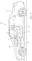
- FIG. 1is a schematic view of a physical state monitoring system for a vehicle occupant in accordance with a first embodiment of the invention
- FIG. 2is a front view of a steering wheel with electrodes of the physical state monitoring system of FIG. 1 in accordance with the first embodiment of the invention
- FIG. 3is a schematic view of a physical state monitoring system for a vehicle occupant in accordance with a second embodiment of the invention
- FIG. 4is a perspective view of headphones with electrodes of the physical state monitoring system of FIG. 3 in accordance with the second embodiment of the invention
- FIG. 5is a schematic view of a physical state monitoring system for a vehicle occupant in accordance with a third embodiment of the invention.
- FIG. 6is a schematic view of a thermoelectric generator system for a vehicle in accordance with a fourth embodiment of the invention.
- a physical state monitoring systemthat is configured to determine a physical state of a vehicle occupant within a vehicle is presented herein.
- the systemincludes electrodes that are formed of carbon nanotubes and/or nanoscale metal fibers.
- nanoscale metal fibersmay be nanoscale stainless steel fibers, metal nanowires, and/or nanoscale metal plated carbon fibers, e.g., copper-plated carbon fibers or nickel-plated carbon fibers.
- nanoscale fibershave a diameter between 1 and 100 nanometers while the length of the fibers may exceed 100 nanometers and be in the micron or millimeter range.
- the electrodesare in contact with the vehicle occupant and, based on the configuration of the electrodes, able to generate a signal that allows a properly configured controller in communication with the electrodes to determine a heart rate of the vehicle occupant, brain wave activity of the vehicle occupant, or concentration of a substance, such as hormones or neurotransmitters in the sweat of the vehicle occupant. Based on the heart rate, brain wave, or concentration data, the controller may then cause the vehicle to take countermeasures to improve the physical state of the vehicle occupant. For example, if the controller detects an elevated heart rate that indicates that the vehicle occupant is stressed, the controller may reduce the volume of the in-vehicle entertainment system or limit and prioritize messages presented to the occupant in order to help reduce stress levels.
- the controllermay be configured to:
- the carbon nanotubes and/or nanoscale metal fibers used to form the electrodes may be incorporated intocan be applied to the following portions of the vehicle interior:
- FIGS. 1 and 2illustrate a non-limiting example of a physical state monitoring system 100 .
- the system 100is incorporated into a motor vehicle 102 such as an automobile, light truck, or commercial vehicle.
- the systemis configured to determine a physical state of a vehicle occupant 104 .
- the systemincludes pair of electrodes 106 that are interconnected to a controller 108 that is configured to determine a voltage difference between the electrodes 106 .
- a controllerincludes a central processing unit (not shown) that may be a microprocessor, application specific integrated circuit (ASIC), or built from discrete logic and timing circuits.
- Software instructions that program the controllermay be stored in a non-volatile (NV) memory device (not shown).
- the NV memory devicemay be contained within the microprocessor or ASIC or it may be a separate device.
- Non-limiting examples of the types of NV memory that may be usedinclude electrically erasable programmable read only memory (EEPROM), masked read only memory (ROM), and flash memory.
- the controllermay also include a wired transceiver (not shown), such as a controller area network (CAN) transceiver, to allow the controller to establish electrical communication with other vehicle systems.
- CANcontroller area network
- the controllermay also include analog to digital (A/D) convertor circuitry (not shown) to convert voltages from the electrodes to digital information.
- A/D convertor circuitsmay be incorporated into the electrodes.
- the electrodesmay be interconnected to the controller via a hard-wired connection or a wireless connection.
- the electrodes 106 connected to the controller 108are formed from nanoscale metal fibers or carbon nanotubes that are incorporated into a conductive film material, such as a polymer-based film.
- This film materialmay be a separate film applied to a vehicle 102 interior surface or may be integral to an exterior layer of the vehicle 102 interior surface. All of these electrodes 106 are in contact with the vehicle occupant 104 , for example the electrodes 106 are in contact with the skin surface of the vehicle occupant 104 .
- the electrodes 106are placed on the steering wheel 110 of the vehicle 102 in a location in which the skin of the vehicle occupant's hands 112 would normally be in contact with the electrodes (10 o'clock and 2 o'clock positions).
- the controller 108is configured to determine the voltage potential difference between the two electrodes 106 and determine the heart rate of the vehicle occupant 104 based on a change in the voltage potential difference between the electrodes 106 .
- the controller 108is also configured to cause the vehicle system 114 initiate the countermeasure if the heart rate is not within a predetermined range, e.g., a heart rate above 120 beats per minute (BPM) may indicate that the vehicle occupant 104 is stressed.
- a predetermined rangemay be reconfigurable to accommodate the physiology of a particular vehicle occupant 104 .
- the controller 108may be further configured to determine a state of alertness of the vehicle occupant 104 based on the heart rate. Studies have shown a correlation the state of alertness and heart rate, specifically a higher state of alertness is correlated with a higher heart rate. If the detected heart rate falls into a range associated with a low level of alertness, the controller 108 may initiate a countermeasure in a vehicle system 114 , such as commanding the heating, ventilation, and air conditioning (HVAC) system to reduce the temperature in the vehicle interior.
- HVACheating, ventilation, and air conditioning
- the controller 108may be further configured to determine a presence of the vehicle occupant 104 in the based on the detection of a heart rate when such an occupant would not be expected, for example a child remaining in the vehicle 102 when the vehicle 102 is turned off and locked. The controller 108 may then cause the vehicle system 114 to initiate the countermeasure, such as such as generating an alarm to alert a responsible authority and/or activate the HVAC system bring the temperature within the passenger compartment to a safe level.
- the countermeasuresuch as such as generating an alarm to alert a responsible authority and/or activate the HVAC system bring the temperature within the passenger compartment to a safe level.
- Electrodesare incorporated into interior surfaces of the vehicle, such as a seat, headrest, or seat belt may also be envisioned.
- FIGS. 3 and 4illustrate another non-limiting example of a physical state monitoring system 200 .
- the controller 208 in this system 200is configured to determine a voltage potential difference between two electrodes 206 formed from nanoscale metal fibers or carbon nanotubes and determine brain wave activity of the vehicle occupant 204 based on a change in the voltage potential difference between the two electrodes 206 .
- the controller 208is further configured to determine the physical state of the vehicle occupant 204 based on the brain wave activity and cause a vehicle system 214 to initiate the countermeasure based on the brain wave activity. As shown in FIG.
- the electrodes 206that are formed of carbon nanotubes, nanoscale stainless steel fibers, metal nanowires, and/or nanoscale metal plated carbon fibers, e.g., copper-plated carbon fibers or nickel-plated carbon fibers are incorporated in a polymeric foam material 216 and contained in a headset 218 that is in contact with the vehicle occupant's head 220 .
- Alternative embodiments of the system 200may be envisioned in which the electrodes 206 are incorporated into a cloth material and contained in an item such as a headband, a headrest, or a helmet.
- FIG. 5illustrates yet another non-limiting example of a physical state monitoring system 300 .
- This system 300includes an electrode 306 formed from nanoscale metal fibers or carbon nanotubes that is configured to detect a concentration level of a substance, such as a hormone or neurotransmitter, in sweat of the vehicle occupant 304 .
- the controller 308 connected to the electrode 306may be configured to detect the determine the concentration level of a substance based upon the output of the electrode 306 and determine the physical state of the vehicle occupant 304 based on the concentration level of the substance.
- the controller 308will then instruct the vehicle system 314 to initiate the countermeasure if the concentration level is not within a predetermined range.
- the electrode 306may be configured to detect a hormone associated with stress, such as cortisol, and the controller 308 will then initiate a countermeasure to reduce stress if the level detected by the controller 308 exceeds the predetermined limit.
- the electrode 306may alternatively configured to detect a hormone, such as insulin that is indicative of the health of the vehicle occupant 304 . If the inulin level determined by the controller 308 is outside the predetermined range, the controller 308 may command the vehicle system 314 to initiate a safety countermeasure, such as commanding the vehicle's telematics system to issue an emergency call to an emergency response center.
- the electrode 306is incorporated into a cloth material forming an interior surface of the vehicle 302 that is in contact with a portion of the vehicle occupant 304 that is prone to sweating, such as a seat, an arm rest, a seat belt, or a head rest.
- the electrode 306may be incorporated into a conductive film material, such as a polymer-based film, forming an interior surface of the vehicle 302 such as a seat, an arm rest, a head rest, or a seat belt.
- the seat or steering wheelmay contain a heating circuit (not shown) that is periodically activated by the controller 308 to cause the vehicle occupant 304 to produce sweat that may be analyzed by the system 300 .
- FIG. 6illustrates a non-limiting example of a thermoelectric generator system 400 that is configured to generate electricity based upon a temperature difference between a vehicle occupant 404 and a portion of a vehicle interior.
- This system 400includes a thermoelectric device 422 containing nanoscale metal fibers or carbon nanotubes that is incorporated into an interior surface of the vehicle 402 and connected to the electrical system 424 of the vehicle 402 .
- the thermoelectric device 422has a first side that is in contact with the vehicle occupant 404 and a second side that is in contact with the portion of the vehicle interior.
- the thermoelectric device 422is configured to supply electrical power to the electrical system 424 of the vehicle 402 .
- the thermoelectric device 422is incorporated into a cloth material forming the interior surface of the vehicle 402 such as a seat, an arm rest, a head rest, or a seat belt. Alternatively, the thermoelectric device 422 may be incorporated into a conductive film material forming the interior surface of the vehicle 402 such as a seat, an arm rest, a head rest, a steering wheel, a door panel, a door handle, or a control button.
- the system 400may include a controller 408 that configures the electrical system 424 to provide electrical power to the thermoelectric device 422 , thereby heating the portion of the vehicle interior. The controller 408 may further configure the electrical system 424 to provide electrical power to the thermoelectric device 422 having a reversed polarity, thereby cooling the portion of the vehicle interior.
- a system 100 , 200 , 300configured to monitor a physical state of a vehicle occupant within a vehicle.
- These physical state monitoring systemsinclude electrodes that are formed of nanoscale metal fibers or carbon nanotubes that are incorporated into cloth materials or conductive films forming interior surfaces of the vehicle such as seat fabrics, arm rests, steering wheels, head rests, door handles, seat belts, baby/child seats, and/or control buttons.
- These physical state monitoring systemsdetermine the physical state of a vehicle occupant based on heart rate, brain wave activity, or secreted hormone/neurotransmitters.
- a system 400 for generating electricity based upon a temperature difference between a vehicle occupant and a portion of a vehicle interioris also provided.
- thermoelectric devicethat is also formed of nanoscale metal fibers or carbon nanotubes that are incorporated into cloth materials or conductive films forming interior surfaces of the vehicle such as seat fabrics, arm rests, steering wheels, head rests, door handles, seat belts, baby/child seats, and/or control buttons.
Landscapes
- Health & Medical Sciences (AREA)
- Biochemistry (AREA)
- General Physics & Mathematics (AREA)
- Life Sciences & Earth Sciences (AREA)
- Chemical & Material Sciences (AREA)
- Analytical Chemistry (AREA)
- Pathology (AREA)
- General Health & Medical Sciences (AREA)
- Physics & Mathematics (AREA)
- Immunology (AREA)
- Nuclear Medicine, Radiotherapy & Molecular Imaging (AREA)
- Investigating, Analyzing Materials By Fluorescence Or Luminescence (AREA)
- Seats For Vehicles (AREA)
- Measuring And Recording Apparatus For Diagnosis (AREA)
- Measurement And Recording Of Electrical Phenomena And Electrical Characteristics Of The Living Body (AREA)
Abstract
Description
- provide an alert for a person unexpectedly left in the vehicle after exiting the vehicle;
- provide an alert for a person unexpectedly in the vehicle before entering the vehicle;
- determine alertness of the vehicle occupant by monitoring brain wave activity;
- determine alertness or mood of the vehicle occupant by monitoring hormone levels;
- determine alertness or mood of the vehicle occupant by monitoring neurotransmitter levels;
- determine alertness or physical state of the vehicle occupant by monitoring heart rate;
- sense the presence of the vehicle occupant by touch;
- adjust heating, ventilation and air conditioning system automatically based on sweating of the vehicle occupant; and
- generate electricity from a temperature difference between the vehicle occupant and the vehicle interior.
- The preceding list in not exhaustive and is non-limiting.
- seat fabrics;
- arm rests;
- steering wheels;
- head rests;
- door handles;
- seat belts;
- baby/child seats;
- control buttons;
- wrist bands;
- headsets;
- headbands;
- skin patches; and
- helmet like headrest with foam electrodes.
- The preceding list in not exhaustive and is non-limiting.
Claims (17)
Priority Applications (1)
| Application Number | Priority Date | Filing Date | Title |
|---|---|---|---|
| US17/241,155US11474041B2 (en) | 2017-04-18 | 2021-04-27 | Sensor for monitoring the physical state of a vehicle occupant |
Applications Claiming Priority (3)
| Application Number | Priority Date | Filing Date | Title |
|---|---|---|---|
| US15/490,289US10377386B2 (en) | 2017-04-18 | 2017-04-18 | System for monitoring the physical state of a vehicle occupant |
| US16/542,900US10801963B2 (en) | 2018-08-22 | 2019-08-16 | Raman spectroscopy for minerals identification |
| US17/241,155US11474041B2 (en) | 2017-04-18 | 2021-04-27 | Sensor for monitoring the physical state of a vehicle occupant |
Related Parent Applications (1)
| Application Number | Title | Priority Date | Filing Date |
|---|---|---|---|
| US16/542,900ContinuationUS10801963B2 (en) | 2017-04-18 | 2019-08-16 | Raman spectroscopy for minerals identification |
Publications (2)
| Publication Number | Publication Date |
|---|---|
| US20210255108A1 US20210255108A1 (en) | 2021-08-19 |
| US11474041B2true US11474041B2 (en) | 2022-10-18 |
Family
ID=74659718
Family Applications (1)
| Application Number | Title | Priority Date | Filing Date |
|---|---|---|---|
| US17/241,155ActiveUS11474041B2 (en) | 2017-04-18 | 2021-04-27 | Sensor for monitoring the physical state of a vehicle occupant |
Country Status (5)
| Country | Link |
|---|---|
| US (1) | US11474041B2 (en) |
| EP (1) | EP4014017A4 (en) |
| JP (1) | JP2022545405A (en) |
| CA (1) | CA3148141A1 (en) |
| WO (1) | WO2021034456A2 (en) |
Families Citing this family (1)
| Publication number | Priority date | Publication date | Assignee | Title |
|---|---|---|---|---|
| KR102666454B1 (en)* | 2023-07-06 | 2024-05-17 | 국립공주대학교 산학협력단 | System and method for mineral composition analysis using x-ray diffraction based on machine learning utilizing domain knowledge |
Citations (12)
| Publication number | Priority date | Publication date | Assignee | Title |
|---|---|---|---|---|
| US5214503A (en) | 1992-01-31 | 1993-05-25 | The United States Of America As Represented By The Secretary Of The Army | Color night vision camera system |
| USH1599H (en) | 1995-07-05 | 1996-10-01 | The United States Of America As Represented By The Secretary Of The Air Force | Synthetic-color night vision |
| US20030218676A1 (en) | 2002-05-23 | 2003-11-27 | Visteon Global Technologies, Inc. | Image enhancement in far infrared camera |
| US20060088298A1 (en) | 2002-05-08 | 2006-04-27 | Ball Aerospace & Technologies Corp. | One chip camera with color sensing capability and high limiting resolution |
| US20120147243A1 (en) | 2010-12-13 | 2012-06-14 | Research In Motion Limited | System and method of capturing low-light images on a mobile device |
| US20130087180A1 (en) | 2011-10-10 | 2013-04-11 | Perpetua Power Source Technologies, Inc. | Wearable thermoelectric generator system |
| US20150201837A1 (en) | 2014-01-20 | 2015-07-23 | Korea Institute Of Science And Technology | Non-invasive health indicator monitoring system and using method thereof |
| US20160082806A1 (en) | 2014-09-22 | 2016-03-24 | Hyundai Motor Company | Air-conditioning system for vehicle |
| US20160118566A1 (en) | 2014-10-23 | 2016-04-28 | Samsung Electronics Co., Ltd. | Wearable device having thermoelectric generator |
| WO2016138087A1 (en) | 2015-02-24 | 2016-09-01 | Eccrine Systems, Inc. | Dynamic sweat sensor management |
| US9603560B2 (en) | 2012-01-26 | 2017-03-28 | The University Of Akron | Flexible electrode for detecting changes in temperature, humidity, and sodium ion concentration in sweat |
| US9751534B2 (en)* | 2013-03-15 | 2017-09-05 | Honda Motor Co., Ltd. | System and method for responding to driver state |
Family Cites Families (15)
| Publication number | Priority date | Publication date | Assignee | Title |
|---|---|---|---|---|
| US20040252299A9 (en)* | 2000-01-07 | 2004-12-16 | Lemmo Anthony V. | Apparatus and method for high-throughput preparation and spectroscopic classification and characterization of compositions |
| US6834122B2 (en)* | 2000-01-22 | 2004-12-21 | Kairos Scientific, Inc. | Visualization and processing of multidimensional data using prefiltering and sorting criteria |
| US7647092B2 (en)* | 2002-04-05 | 2010-01-12 | Massachusetts Institute Of Technology | Systems and methods for spectroscopy of biological tissue |
| US7471390B2 (en)* | 2006-03-03 | 2008-12-30 | Thermo Electron Scientific Instruments, Llc | Spectrometer signal quality improvement via background subtraction |
| WO2012024347A1 (en)* | 2010-08-16 | 2012-02-23 | The University Of Chicago | Real-time mapping of electronic structure with single-shot two-dimensional electronic spectroscopy |
| US9417332B2 (en)* | 2011-07-15 | 2016-08-16 | Cardinal Health 414, Llc | Radiopharmaceutical CZT sensor and apparatus |
| US8982338B2 (en)* | 2012-05-31 | 2015-03-17 | Thermo Scientific Portable Analytical Instruments Inc. | Sample analysis |
| US9075015B2 (en)* | 2012-06-04 | 2015-07-07 | Frederick W. Shapiro | Universal tool for automated gem and mineral identification and measurement |
| GB2513343A (en)* | 2013-04-23 | 2014-10-29 | Univ Singapore | Methods related to instrument-independent measurements for quantitative analysis of fiber-optic Raman spectroscopy |
| CN104749155B (en)* | 2013-12-27 | 2018-01-16 | 同方威视技术股份有限公司 | For detecting the Raman spectra detection process of the sample contained in body |
| SG10201501196PA (en)* | 2015-02-16 | 2016-09-29 | Lighthaus Photonics Pte Ltd | Compact spectrometer |
| EP3427287A1 (en)* | 2016-03-07 | 2019-01-16 | Micromass UK Limited | Spectrometric analysis |
| US20190257693A1 (en)* | 2016-06-16 | 2019-08-22 | Valisure Llc | Methods and systems for spectroscopic analysis |
| EP3740121A4 (en)* | 2018-01-17 | 2021-12-15 | ODS Medical Inc. | SYSTEM AND METHOD OF REAL-TIME RAMAN SPECTROSCOPY FOR CANCER DETECTION |
| US10663345B2 (en)* | 2018-08-22 | 2020-05-26 | Paul Bartholomew | Raman spectroscopy for minerals identification |
- 2020
- 2020-07-27CACA3148141Apatent/CA3148141A1/enactivePending
- 2020-07-27JPJP2022510115Apatent/JP2022545405A/ennot_activeWithdrawn
- 2020-07-27WOPCT/US2020/043691patent/WO2021034456A2/ennot_activeCeased
- 2020-07-27EPEP20855047.5Apatent/EP4014017A4/ennot_activeWithdrawn
- 2021
- 2021-04-27USUS17/241,155patent/US11474041B2/enactiveActive
Patent Citations (12)
| Publication number | Priority date | Publication date | Assignee | Title |
|---|---|---|---|---|
| US5214503A (en) | 1992-01-31 | 1993-05-25 | The United States Of America As Represented By The Secretary Of The Army | Color night vision camera system |
| USH1599H (en) | 1995-07-05 | 1996-10-01 | The United States Of America As Represented By The Secretary Of The Air Force | Synthetic-color night vision |
| US20060088298A1 (en) | 2002-05-08 | 2006-04-27 | Ball Aerospace & Technologies Corp. | One chip camera with color sensing capability and high limiting resolution |
| US20030218676A1 (en) | 2002-05-23 | 2003-11-27 | Visteon Global Technologies, Inc. | Image enhancement in far infrared camera |
| US20120147243A1 (en) | 2010-12-13 | 2012-06-14 | Research In Motion Limited | System and method of capturing low-light images on a mobile device |
| US20130087180A1 (en) | 2011-10-10 | 2013-04-11 | Perpetua Power Source Technologies, Inc. | Wearable thermoelectric generator system |
| US9603560B2 (en) | 2012-01-26 | 2017-03-28 | The University Of Akron | Flexible electrode for detecting changes in temperature, humidity, and sodium ion concentration in sweat |
| US9751534B2 (en)* | 2013-03-15 | 2017-09-05 | Honda Motor Co., Ltd. | System and method for responding to driver state |
| US20150201837A1 (en) | 2014-01-20 | 2015-07-23 | Korea Institute Of Science And Technology | Non-invasive health indicator monitoring system and using method thereof |
| US20160082806A1 (en) | 2014-09-22 | 2016-03-24 | Hyundai Motor Company | Air-conditioning system for vehicle |
| US20160118566A1 (en) | 2014-10-23 | 2016-04-28 | Samsung Electronics Co., Ltd. | Wearable device having thermoelectric generator |
| WO2016138087A1 (en) | 2015-02-24 | 2016-09-01 | Eccrine Systems, Inc. | Dynamic sweat sensor management |
Non-Patent Citations (3)
| Title |
|---|
| "Self-adhesive epidermal carbon nanotube electronics for tether-free long-term continuous recording of biosignals", Seung Min Lee, et al., Aug. 15, 2014, pp. 1-9. |
| Self-adhesive epidermal carbon nanotube electronics for tether-free long-term continuous recording of biosignals;Seung Min Lee1 (Year: 2014).* |
| Thermoelectric "Fabrics" based on carbon nanotube composites, David L. Carroll, Center for Nanotechnology and Molecular Materials, Department of Physics, Wake Forest University, Winston-Salem NC https://energy.gov/sites/prod/files/2014/03/f10/carroll_0.pdf. |
Also Published As
| Publication number | Publication date |
|---|---|
| EP4014017A4 (en) | 2023-10-25 |
| WO2021034456A3 (en) | 2021-04-01 |
| EP4014017A2 (en) | 2022-06-22 |
| CA3148141A1 (en) | 2021-02-25 |
| US20210255108A1 (en) | 2021-08-19 |
| WO2021034456A2 (en) | 2021-02-25 |
| JP2022545405A (en) | 2022-10-27 |
Similar Documents
| Publication | Publication Date | Title |
|---|---|---|
| US11021162B2 (en) | System for generating electricity in a vehicle | |
| US11254209B2 (en) | System and method for controlling vehicle systems in a vehicle | |
| US11383721B2 (en) | System and method for responding to driver state | |
| US10210409B1 (en) | Seating system with occupant stimulation and sensing | |
| US9463805B2 (en) | System and method for dynamic vehicle control affecting sleep states of vehicle occupants | |
| US10358034B2 (en) | System and method for controlling a vehicle display in a moving vehicle | |
| JP3843958B2 (en) | Seat temperature control system | |
| EP3683623B1 (en) | System and method for responding to driver state | |
| CN105015445B (en) | Driver used for vehicles carries out the method and system of auxiliary relevant to people | |
| CN104908687B (en) | Method for allowing an increased performance nap in a motor vehicle | |
| US10434965B2 (en) | Vehicular safety seat, controller coupled with vehicular safety seat, and vehicular safety seat system | |
| US20190184853A1 (en) | Occupant sensing system for a vehicle | |
| US11474041B2 (en) | Sensor for monitoring the physical state of a vehicle occupant | |
| US11479172B2 (en) | Unattended occupant alarm assembly | |
| JP6617686B2 (en) | Wireless power feeding system and power transmission / reception monitoring program | |
| US20190092127A1 (en) | Temperature Remediation in Unattended Vehicles | |
| WO2015118569A1 (en) | Child car seat with forgotten-child alarm system | |
| US12141432B2 (en) | Vehicle occupant detection system | |
| JPH10278541A (en) | Vehicle snooze prevention device | |
| JP6220177B2 (en) | Seat belt alarm device | |
| CN115053299A (en) | Method for determining motion sickness | |
| CN119459732A (en) | Vehicle control method, electronic device and vehicle | |
| EP3102459A1 (en) | Child car seat with forgotten-child alarm system | |
| ITTO990614A1 (en) | SYSTEM FOR THE ERGONOMIC ADJUSTMENT OF DEVICES IN MOTOR VEHICLES |
Legal Events
| Date | Code | Title | Description |
|---|---|---|---|
| AS | Assignment | Owner name:APTIV TECHNOLOGIES LIMITED, BARBADOS Free format text:ASSIGNMENT OF ASSIGNORS INTEREST;ASSIGNORS:RICHMOND, ZACHARY J.;RUBINO, EVANGELIA;SEIDLER, ROBERT J.;SIGNING DATES FROM 20190620 TO 20191111;REEL/FRAME:056049/0278 | |
| FEPP | Fee payment procedure | Free format text:ENTITY STATUS SET TO UNDISCOUNTED (ORIGINAL EVENT CODE: BIG.); ENTITY STATUS OF PATENT OWNER: LARGE ENTITY | |
| STPP | Information on status: patent application and granting procedure in general | Free format text:APPLICATION DISPATCHED FROM PREEXAM, NOT YET DOCKETED | |
| STPP | Information on status: patent application and granting procedure in general | Free format text:DOCKETED NEW CASE - READY FOR EXAMINATION | |
| STPP | Information on status: patent application and granting procedure in general | Free format text:NON FINAL ACTION MAILED | |
| STPP | Information on status: patent application and granting procedure in general | Free format text:RESPONSE TO NON-FINAL OFFICE ACTION ENTERED AND FORWARDED TO EXAMINER | |
| STPP | Information on status: patent application and granting procedure in general | Free format text:NOTICE OF ALLOWANCE MAILED -- APPLICATION RECEIVED IN OFFICE OF PUBLICATIONS | |
| STPP | Information on status: patent application and granting procedure in general | Free format text:PUBLICATIONS -- ISSUE FEE PAYMENT VERIFIED | |
| STCF | Information on status: patent grant | Free format text:PATENTED CASE | |
| AS | Assignment | Owner name:APTIV TECHNOLOGIES (2) S.A R.L., LUXEMBOURG Free format text:ENTITY CONVERSION;ASSIGNOR:APTIV TECHNOLOGIES LIMITED;REEL/FRAME:066746/0001 Effective date:20230818 Owner name:APTIV TECHNOLOGIES AG, SWITZERLAND Free format text:ASSIGNMENT OF ASSIGNORS INTEREST;ASSIGNOR:APTIV MANUFACTURING MANAGEMENT SERVICES S.A R.L.;REEL/FRAME:066551/0219 Effective date:20231006 Owner name:APTIV MANUFACTURING MANAGEMENT SERVICES S.A R.L., LUXEMBOURG Free format text:MERGER;ASSIGNOR:APTIV TECHNOLOGIES (2) S.A R.L.;REEL/FRAME:066566/0173 Effective date:20231005 |