US11471680B2 - Systems and interfaces for ocular therapy - Google Patents
Systems and interfaces for ocular therapyDownload PDFInfo
- Publication number
- US11471680B2 US11471680B2US16/844,421US202016844421AUS11471680B2US 11471680 B2US11471680 B2US 11471680B2US 202016844421 AUS202016844421 AUS 202016844421AUS 11471680 B2US11471680 B2US 11471680B2
- Authority
- US
- United States
- Prior art keywords
- user
- eye
- therapy apparatus
- electrode
- wearable
- Prior art date
- Legal status (The legal status is an assumption and is not a legal conclusion. Google has not performed a legal analysis and makes no representation as to the accuracy of the status listed.)
- Active, expires
Links
Images


Classifications
- A—HUMAN NECESSITIES
- A61—MEDICAL OR VETERINARY SCIENCE; HYGIENE
- A61N—ELECTROTHERAPY; MAGNETOTHERAPY; RADIATION THERAPY; ULTRASOUND THERAPY
- A61N1/00—Electrotherapy; Circuits therefor
- A61N1/02—Details
- A61N1/04—Electrodes
- A61N1/0404—Electrodes for external use
- A61N1/0408—Use-related aspects
- A—HUMAN NECESSITIES
- A61—MEDICAL OR VETERINARY SCIENCE; HYGIENE
- A61N—ELECTROTHERAPY; MAGNETOTHERAPY; RADIATION THERAPY; ULTRASOUND THERAPY
- A61N1/00—Electrotherapy; Circuits therefor
- A61N1/02—Details
- A61N1/04—Electrodes
- A61N1/0404—Electrodes for external use
- A61N1/0472—Structure-related aspects
- A—HUMAN NECESSITIES
- A61—MEDICAL OR VETERINARY SCIENCE; HYGIENE
- A61N—ELECTROTHERAPY; MAGNETOTHERAPY; RADIATION THERAPY; ULTRASOUND THERAPY
- A61N1/00—Electrotherapy; Circuits therefor
- A61N1/02—Details
- A61N1/08—Arrangements or circuits for monitoring, protecting, controlling or indicating
- A—HUMAN NECESSITIES
- A61—MEDICAL OR VETERINARY SCIENCE; HYGIENE
- A61N—ELECTROTHERAPY; MAGNETOTHERAPY; RADIATION THERAPY; ULTRASOUND THERAPY
- A61N1/00—Electrotherapy; Circuits therefor
- A61N1/18—Applying electric currents by contact electrodes
- A61N1/32—Applying electric currents by contact electrodes alternating or intermittent currents
- A61N1/36—Applying electric currents by contact electrodes alternating or intermittent currents for stimulation
- A61N1/36046—Applying electric currents by contact electrodes alternating or intermittent currents for stimulation of the eye
- A—HUMAN NECESSITIES
- A61—MEDICAL OR VETERINARY SCIENCE; HYGIENE
- A61N—ELECTROTHERAPY; MAGNETOTHERAPY; RADIATION THERAPY; ULTRASOUND THERAPY
- A61N1/00—Electrotherapy; Circuits therefor
- A61N1/18—Applying electric currents by contact electrodes
- A61N1/32—Applying electric currents by contact electrodes alternating or intermittent currents
- A61N1/36—Applying electric currents by contact electrodes alternating or intermittent currents for stimulation
- A61N1/372—Arrangements in connection with the implantation of stimulators
- A61N1/37211—Means for communicating with stimulators
- A61N1/37252—Details of algorithms or data aspects of communication system, e.g. handshaking, transmitting specific data or segmenting data
- A61N1/37282—Details of algorithms or data aspects of communication system, e.g. handshaking, transmitting specific data or segmenting data characterised by communication with experts in remote locations using a network
- A—HUMAN NECESSITIES
- A61—MEDICAL OR VETERINARY SCIENCE; HYGIENE
- A61N—ELECTROTHERAPY; MAGNETOTHERAPY; RADIATION THERAPY; ULTRASOUND THERAPY
- A61N1/00—Electrotherapy; Circuits therefor
- A61N1/02—Details
- A61N1/04—Electrodes
- A61N1/0404—Electrodes for external use
- A61N1/0472—Structure-related aspects
- A61N1/0484—Garment electrodes worn by the patient
- A—HUMAN NECESSITIES
- A61—MEDICAL OR VETERINARY SCIENCE; HYGIENE
- A61N—ELECTROTHERAPY; MAGNETOTHERAPY; RADIATION THERAPY; ULTRASOUND THERAPY
- A61N1/00—Electrotherapy; Circuits therefor
- A61N1/02—Details
- A61N1/08—Arrangements or circuits for monitoring, protecting, controlling or indicating
- A61N2001/083—Monitoring integrity of contacts, e.g. by impedance measurement
Definitions
- the present inventionrelates generally to the field of delivery of therapeutic energy for treatment of various conditions. More particularly, the present invention is directed to systems and methods adapted to deliver energy to the eye and/or surrounding tissue.
- ASDage related macular degeneration
- maladiesincluding inherited diseases such as Stargardt's disease, Retinitis Pigmentosa, and other degenerative conditions that affect the retina of the eye.
- a wide variety of other vision disordersexist which can lead to partial or total blindness.
- new, adjunctive, and/or alternative systems and methods to treat such disordersincluding by preventing, arresting or reversing disease progress, or at least by alleviating ongoing symptoms.
- a variety of proposed head worn apparatuseshave been disclosed for the delivery of electrical stimulus (sometimes referred to as microcurrent therapy) to the eye. Patches, goggles, and devices resembling glasses have been proposed.
- improved head worn apparatusesfor delivering therapy to persons afflicted with diseases of the eye, as well as other conditions (headaches, sleep disorders, fatigue) that may be treated by delivering therapy to the eye and/or surrounding tissue.
- the present inventorshave recognized, among other things, that a problem to be solved is the need for new patient interfaces for delivering energy and/or therapy to the eye and surrounding tissues.
- One form of energy deliveryis electrical therapy which, when applied to the eye may be referred to as “ocular modulation.”
- Such therapymay be electrocurrent therapy, microcurrent therapy or millicurrent therapy, without intending to limit the scope of the invention to a particular range of current with such terms.
- Existing apparatuses and the patent artsshow various apparatuses having a variety of drawbacks. Some products require a plurality of wires to be managed by the patient or user, who may need to use the product independently and/or outside of the clinical environment. For users suffering from impaired vision, adding the difficulty of managing numerous wires can lead to frustration and eventual non-use of therapy products. Some known apparatuses are heavy and bulky, and prevent the user from comfortably relaxing during use. New devices with less wires and less bulk are desired.
- a first illustrative and non-limiting exampletakes the form of a wearable therapy apparatus for placement about the eye of a user comprising a perimeter region including a tissue interface, the perimeter region having a superior edge, and an inferior edge and at least one electrode; a field region defined within the perimeter region; and an electronics module electrically coupled to the at least one electrode, the electronics module adapted to deliver electrical stimulus to the user through the at least one electrode.
- the perimeter regionmay include an open side. Additionally or alternatively, the perimeter region may comprise a superior arm and an inferior arm, and at least one of the superior arm and inferior arm is flexible to allow compression thereof in a superior-inferior direction prior to placement about the eye of a user, such that release of the compression provide a mechanical force to the tissue surrounding the user's eye aiding in fixation in a desired position.
- the perimeter regionmay comprise a hinging side opposite the open side, the hinging side adapted to allow the superior arm and inferior arm to be pressed toward one another prior to placement about the eye of a user, such that release of the superior and inferior arms in a desired position provides a mechanical force to the tissue surrounding the user's eye aiding in fixation in a desired position.
- the mechanical force to the tissue surrounding the user's eyemay be sufficient to hold the apparatus in place without the use of an adhesive.
- the apparatusmay further comprising an adhesive element sized and shaped for use with at least one of the superior and inferior arms to provide fixation to the skin of the user.
- the perimeter regionmay comprise a shape memory material.
- the perimeter regionmay comprise a spring. Additionally or alternatively, the at least one electrode may comprise a superior electrode on the superior arm, and an inferior electrode on the inferior arm. Additionally or alternatively, the superior arm may comprise a bridge coupled to one or more electrode arms carrying an electrode. Additionally or alternatively, the inferior arm may comprise a bridge coupled to one or more electrode arms carrying an electrode. Additionally or alternatively, the superior arm may comprise a bridge coupled to a strut which holds an electrode carrier having one or more electrodes thereon. Additionally or alternatively, the inferior arm may comprise a bridge coupled to a strut which holds an electrode carrier having one or more electrodes thereon. Additionally or alternatively, the apparatus may comprise a nasal edge opposite the open side.
- the apparatusmay comprise a temporal edge opposite the open side. Additionally or alternatively, the apparatus may comprise a temporal portion shaped and sized to extend from the eyepiece to the temple of a user when the eyepiece is placed about the eye of a user. Additionally or alternatively, the electronics module may be carried on the temporal portion. Additionally or alternatively, the temporal portion may comprise a port to receive the electronics module. Additionally or alternatively, the temporal portion may comprise a port for receiving a replaceable battery for providing power to the electronics module. Additionally or alternatively, the temporal portion may comprise a temporal electrode for electrically coupling to the temple.
- the field regionmay form, define, or include a void.
- the wearable therapy apparatusmay comprise a temporal portion connected to the perimeter region and shaped and sized to extend from the perimeter region to the temple of a user when the perimeter region is placed about the eye of a user.
- the perimetermay be closed to completely surround the eye of a user when placed thereabout. Additionally or alternatively, the perimeter region may be flexible to allow compression thereof in a superior-inferior direction prior to placement about the eye of a user, such that release of the compression provide a mechanical force to the tissue surrounding the user's eye aiding in fixation in a desired position. Additionally or alternatively, the perimeter region may comprise a hinge adapted to allow compression thereof prior to placement about the eye of a user, such that release of such compression provides a mechanical force to the tissue surrounding the user's eye thereby aiding in fixation in a desired position. Additionally or alternatively, the mechanical force to the tissue surrounding the user's eye may be sufficient to hold the apparatus in place without the use of an adhesive.
- the apparatusmay comprise an adhesive element sized and shaped for placement on at least a portion of the perimeter to provide fixation to the skin of the user.
- the perimeter regionmay comprise a shape memory material.
- the perimeter regionmay comprise a spring.
- the at least one electrodemay comprise a superior electrode and an inferior electrode.
- the field regionmay comprise a solid member defining an inner perimeter adapted to receive a corrective lens. Additionally or alternatively, the field region may be closed and formed of a transparent or semi-transparent material. Additionally or alternatively, the field region may be flexible in at least a superior/inferior direction to aid in mechanically fixing the apparatus in a desired position about the eye of a user. Additionally or alternatively, the electronics module may be directly coupled to the field region.
- the electronics modulemay be directly coupled to the perimeter region. Additionally or alternatively, the at least one electrode on the perimeter region may comprise at least a first inferior electrode on the inferior edge and at least a first superior electrode on the superior edge. Additionally or alternatively, the tissue interface may be formed of a soft material. Additionally or alternatively, wherein the soft material may be a gel encapsulated in a layer of polymer. Additionally or alternatively, the soft material may be a foam. Additionally or alternatively, the apparatus may further comprise a module port for receiving the electronics module and electrically coupling the electronics module to the electrodes, such that the electronics module may be separated from the rest of the apparatus.
- the perimeter regionmay be flexible in at least one direction and has a rest configuration, such that a force applied to the perimeter region changes the shape of the perimeter region from the rest configuration, to facilitate placement about the eye of a user, and on removal of the applied force, the perimeter region exerts a restorative force to return to the rest configuration, such that the restorative force aids in retention of the wearable therapy apparatus in a desired position about the eye of the user.
- the perimeter regionmay be flexible in at least one direction to allow a user to apply force and reduce the extent of the perimeter in the at least one direction to place the apparatus in the region of the eye of a user, further wherein the perimeter region is resilient to exert a force against the skin and/or bones surrounding the eye of the user, to mechanically hold the apparatus over the eye of the user without the use of an earpiece or strap.
- the perimeter regionmay comprise a compression member that the user can compress for purposes of placing the therapy apparatus in the region of the eye of a user.
- the compression membermay be a spring.
- the compression membermay be a shape memory alloy member.
- the compression membermay be a canister holding a fluid adapted to be compressed.
- the compression membermay be a foam or sponge member.
- the apparatusmay further comprise an adhesive piece sized and shaped for placement over the perimeter region and configured to provide adhesion between the perimeter region and the skin of a user. Additionally or alternatively, the adhesive piece may be disposable.
- An illustrative kitmay comprise the wearable therapy apparatus of the first illustrative and non-limiting example, and a sheet or roll having a plurality of adhesive pieces removeably disposed thereon, the adhesive pieces being double sided. Additionally or alternatively, the apparatus may be configured to be placed over only one eye of a user. Additionally or alternatively, the apparatus may comprising a multi-layer structure with a palpebral layer, an electronics layer, and an outer layer, the electronics layer comprising wire connections to couple the electrodes to the electronics module. Additionally or alternatively, the multi-layer structure may form or make up the field region and at least a portion of the perimeter region.
- the perimeter region and field regionmay make up a first eyepiece having at least a first electrode
- the apparatusmay further comprise a second eyepiece coupled to the first eyepiece by a nosepiece, the second eyepiece having at least a second electrode, wherein the electronics module is electrically coupled to each of the first and second electrodes.
- the electronics modulemay be located on a remote electrode that attaches to the body of a user distant from the eye, and is coupled by a wire to one of the nose piece or the first or second eyepieces.
- the electronics modulemay be carried on the nosepiece or on one of the eyepieces. Additionally or alternatively, the electronics module may be configured to be removed from the therapy apparatus.
- the nosepiecemay carry one or more electrical connectors coupling the first eyepiece to the second eyepiece. Additionally or alternatively, each of the first and second eyepieces may comprise a separate electronics module, and the nosepiece provides a wire providing common ground reference to the electronics modules.
- the apparatusmay comprise a remote electrode coupled by a wire to the wearable therapy apparatus. Additionally or alternatively, the remote electrode may carry a battery, and the wire connects the battery to the electronics module to power the electronic module. Additionally or alternatively, the electronics module may be removeable. Additionally or alternatively, the electronics module may comprise a battery, and the battery is replaceable. Additionally or alternatively, the electronics module may comprise a rechargeable battery and a resonant element adapted to receive power via wireless transmission for recharging the battery.
- the electronics modulemay comprise a rechargeable battery, further comprising external contacts adapted to receive power from a storage case having corresponding contacts for recharging purposes.
- a system examplemay comprise such a therapy apparatus and a storage case having the corresponding contacts.
- the storage casemay comprise a user interface for allowing a user to determine charge status the electronic module rechargeable battery. Additionally or alternatively, the storage case may comprise a user interface for allowing a user to set or modify stimulus settings of the electronics module.
- the electronics modulemay comprise a rechargeable battery and a port adapted to receive a plug on the end of a charging cord, or on the end of a charging and reprogramming cord. Additionally or alternatively, the electronics module may comprise a battery circuit having one rechargeable battery cell or a plurality of rechargeable battery cells, either in one battery or in a battery stack, configured, at full charge, to provide about 10 to about 20 milliamp hours of current capacity at an output voltage of 6 volts or more, capable of providing at least two milliamps of constant current for a duration of at least 30 minutes.
- the electronics modulemay lack any battery and comprises a resonant element adapted to receive power via wireless transmission for recharging the battery, a capacitor to receive power from the resonant element, and a switch configured to close when the capacitor holds enough energy for a stimulus output to be delivered.
- the wearable therapy apparatusmay have a mass of less than about 25 grams. Additionally or alternatively, the wearable therapy apparatus may have a mass of less than about 15 grams. Additionally or alternatively, the wearable therapy apparatus may have a mass of less than about 10 grams. Additionally or alternatively, the wearable therapy apparatus may have a mass of about 5 to about 25 grams. Additionally or alternatively, the wearable therapy apparatus may have a mass of about 5 to about 15 grams. Additionally or alternatively, the wearable therapy apparatus may have a mass of about 3 to about 10 grams.
- the apparatusmay comprise a temperature sensor configured to prevent activation of the electronics module when the wearable therapy apparatus is not on a user's body by sensing body temperature. Additionally or alternatively, the apparatus may comprise a temperature sensor configured to activate stimulus by the electronics module when the wearable therapy apparatus is on a user's head by sensing body temperature. Additionally or alternatively, the apparatus may comprise a motion sensor to sense user motion and determine whether stimulus delivered by the electronics module through the electrodes is causing muscle recruitment.
- the electronics modulemay be configured to sense impedance between the electrodes. Additionally or alternatively, the electronics module may be configured to use sensed impedance to determine whether the wearable therapy apparatus is being worn by a user and, if so, to automatically deliver therapy. Additionally or alternatively, the electronics module may be configured to use sensed impedance to determine whether the wearable therapy apparatus is being worn by a user and, if not, to automatically disable therapy.
- the electronics modulemay include a light indicator placed to indicate to a user whether the wearable therapy apparatus is delivering stimulus. Additionally or alternatively, the apparatus may be configured to deliver stimulus without the use of a remote return electrode. Additionally or alternatively, the apparatus may be configured to deliver stimulus with the use of a remote return electrode.
- the stimulus outputmay be monopolar, bipolar, or other multipolar (such as tripolar), and the stimulus output may be monophasic, biphasic, or other multiphasic (such as triphasic). Additionally or alternatively, the stimulus output may comprise a first train of monophasic output pulses, and a second train of monophasic output pulses of polarity opposite the first train. Additionally or alternatively, the stimulus output may comprise a carrier signal modulated by an envelope, the carrier signal being operated at a first frequency and the envelope at a second frequency, wherein the second frequency is lower than the first frequency. Additionally or alternatively, the output stimulus may be voltage controlled, current controlled, or otherwise controlled for constant power. Additionally or alternatively, the electronics module may be configurable between a first configuration for current controlled output stimulus, and a second configuration for voltage controlled output stimulus.
- a non-limiting first illustrative method exampletakes the form of a method of stimulating tissue to address a disease of the eye comprising placing a wearable therapy apparatus as in the first illustrative, non-limiting example and any of the variants thereof, about the eye of a user.
- the perimeter region of the wearable therapy apparatusis flexible in at least one direction and has a rest configuration, such that a force applied to the perimeter region changes the shape of the perimeter region from the rest configuration, to facilitate placement about the eye of a user, and on removal of the applied force, the perimeter region exerts a restorative force to return to the rest configuration, such that the restorative force aids in retention of the wearable therapy apparatus in a desired position about the eye of the user
- the placing stepcomprises applying a compressive force to the perimeter region of the wearable therapy apparatus to change the shape of the perimeter region from the rest configuration, putting the wearable therapy apparatus at a desired position about the eye of a user, and releasing the compressive force and allowing the restorative force to aid in mechanical fixation of the wearable therapy apparatus in a target position about the eye of the user.
- the restorative forceis exerted, at least in part, by a shape memory material that makes up a part of the wearable therapy apparatus. Additionally or alternatively, the restorative force is exerted, at least in part, by a sponge, a spring, or compressed air.
- the perimeter region of the wearable therapy apparatusis flexible in at least one direction to allow a user to apply force and reduce the extent of the perimeter in the at least one direction in order to place the apparatus in the region of the eye of a user, further wherein the perimeter region is resilient to exert a force against the tissue surrounding the eye of the user, to mechanically hold the apparatus over the eye of the user without the use of an earpiece or strap, and the placing step is performed by applying a placement force to the wearable therapy apparatus to reduce the extent of the perimeter in the at least one direction and then releasing the placement force to allow the perimeter region to exert a staying force against the tissue surrounding the eye of the user.
- the staying forceis exerted, at least in part, by a shape memory material that makes up a part of the wearable therapy apparatus. Additionally or alternatively, the staying force is exerted, at least in part, by a sponge, a spring, or compressed air. Additionally or alternatively to the first illustrative method, the placing step may be performed without the use of an earpiece or strap to hold the wearable therapy apparatus in position.
- the methodmay comprise activating the wearable therapy apparatus to deliver the stimulus via one or more electrodes placed about the eye of the user.
- the wearable therapy apparatuscomprises a temperature sensor and the activating step occurs automatically when the electronics module senses a temperature change by monitoring an output or characteristic of the temperature sensor.
- the wearable therapy apparatuscomprises a button or touch surface adapted to sense touch, and the activating step occurs in response to the button being depressed or the touch surface sensing a touch.
- the electronics modulecomprises or is coupled to a communication circuitry for at least receiving an activation signal, and the activating step occurs when the electronics module recognizes the activation signal, further wherein the activation signal is issued by a smartphone, tablet, computer, or dedicated programming device.
- the methodmay also comprise placing an adhesive piece on at least a portion of the tissue contacting surface of the wearable therapy device to provide fixation force to hold the wearable therapy device in a target position on the patient.
- a non-limiting second illustrative method for treating a disease of the eyecomprises administering a pharmaceutical or biological agent to the eye; and applying electrical stimulation to the eye using a wearable therapy apparatus as in the first illustrative and non-limiting example and/or any variant thereof.
- a non-limiting third illustrative method for treating a disease of the eyecomprises administering a pharmaceutical or biological agent to the eye; and applying electrical stimulation to the eye using a wearable therapy apparatus.
- the pharmaceutical or biological agentmay be a stem cell or plurality of stem cells. Additionally or alternatively to the non-limiting second or third illustrative methods, the pharmaceutical or biological agent may be a pharmaceutical agent. Additionally or alternatively to the non-limiting second or third illustrative methods, the electrical stimulation may be applied before the administering step is performed, such as anywhere from 0 to 96 hours. Additionally or alternatively to the non-limiting second or third illustrative methods, the electrical stimulation may be applied between 0 and 96 hours after the administering step is performed.
- the electrical stimulationmay aid in addressing the disease of the eye when used in combination with the pharmaceutical or biological agent. Additionally or alternatively to the non-limiting second or third illustrative methods, the electrical stimulation may aid in absorption or effectiveness of the pharmaceutical or biological agent. Additionally or alternatively to the non-limiting second or third illustrative methods, the electrical stimulation may reduce a side effect of the pharmaceutical or biological agent. Additionally or alternatively to the non-limiting second or third illustrative methods, the pharmaceutical or biological agent is administered to the vitreous. Additionally or alternatively to the non-limiting second or third illustrative methods, the pharmaceutical or biological agent is administered to the retina.
- a non-limiting container exampletakes the form of a container configured to receive a wearable therapy apparatus, the wearable therapy apparatus comprising one or more electrical contacts that are externally accessible, the container comprising a well having a shape that matches an outer perimeter shape of the wearable therapy apparatus, and one or more receiver contacts placed to electrically couple to the one or more externally accessible electrical contacts of the wearable therapy apparatus.
- the containermay have an outer shell defining and interior and an exterior, the exterior comprising a user interface that is adapted to indicate charge and/or programming status of a wearable therapy apparatus contained therein.
- the containermay further comprise a power supply for providing power for recharging the wearable therapy apparatus, wherein the power supply is at least one of line powered, rechargeable battery, or primary cell battery.
- Yet another illustrative and non-limiting exampletakes the form of a wearable therapy apparatus for placement about an eye of a user comprising a tissue contacting region sized and shaped for placement about the eye, the tissue contacting region comprising at least one electrode thereon for contacting the skin of a user, wherein the tissue contacting region is deformable to allow compression thereof prior to placement about the eye of a user, such that release of the compression provides a mechanical force to the tissue surrounding the user's eye aiding in fixation in a desired position.
- Another illustrative and non-limiting method exampletakes the form of method of delivering energy to address a condition of the eye comprising placing a wearable therapy apparatus about the eye of a user, and activating the wearable therapy apparatus, wherein the wearable therapy apparatus comprises: a perimeter region including a tissue interface having at least one electrode, the perimeter region having a superior edge, and an inferior edge and at least one electrode, the perimeter region sized and shaped for placement about the eye of the user with the superior edge superior to the eye and the inferior edge inferior to the eye; a field region defined within the perimeter region; and an electronics module electrically coupled to the at least one electrode, the electronics module adapted to deliver electrical stimulus to the user through the at least one electrode, wherein the electronics module is carried on at least one of the perimeter region or the field region.
- the electronics modulecomprises a rechargeable or replaceable battery coupled to a pulse generator circuit adapted to generate output pulses, the pulse generator circuit having at least one output coupled to the at least one electrode, and a control circuit configured to determine timing pulse parameters for the output pulses of the pulse generator, wherein the activating step comprises: the control circuit issuing a test signal to determine tissue contact using the at least one electrode; and in response to confirming tissue contact with the at least one electrode, the control circuit controlling the pulse generator to issue output pulses as therapy.
- the perimeter regionis flexible to allow compression thereof in a superior-inferior direction prior to placement about the eye of a user, such that release of the compression provides a mechanical force to the tissue surrounding the user's eye aiding in fixation in a desired position; and the method further comprises a user compressing the perimeter region, placing the wearable therapy device about the eye, and releasing the perimeter region such that the flexible perimeter region provides mechanical force to the tissue surrounding the users eye to hold the wearable therapy device in a desired position.
- FIG. 1shows an illustrative wearable therapy apparatus in a perspective view
- FIG. 2is an elevation view of a palpebral surface of an illustrative wearable therapy apparatus
- FIG. 3is a section view of the wearable therapy apparatus of FIG. 2 ;
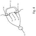
- FIG. 4is a side view of an illustrative wearable therapy apparatus on a user's eyelid
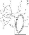
- FIG. 5is an exploded view of an illustrative wearable therapy apparatus
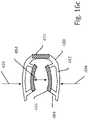
- FIG. 6 ais an elevation view of a palpebral surface of an illustrative wearable therapy apparatus
- FIG. 6 bis an elevation view of an adhesive element for use with the apparatus of FIG. 6 a;
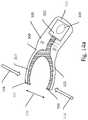
- FIG. 7 ashows an illustrative system having a wearable therapy apparatus with a remote electrode and a case
- FIG. 7 bshows an alternative structure to FIG. 7 a;
- FIGS. 8-10show illustrative electrical architectures for wearable therapy apparatuses
- FIG. 11shows a user with an illustrative wearable therapy apparatus
- FIG. 12shows an illustrative wearable therapy apparatus and adhesive element
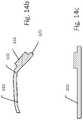
- FIGS. 13 a -13 c , 14 a -14 d , 15 a -15 c , 16 a -16 c , and 17each show illustrative wearable therapy apparatuses.
- FIGS. 18-19show illustrative systems having a nosepiece coupling together two illustrative wearable therapy apparatuses for placement about the eye.
- the present inventionis generally directed to systems for delivering stimulus to the eye of a patient or user.
- Some patientsmay have a disease of the eye, such as one or more of the following: macular degeneration, inherited retinal disease, presbyopia, diabetic retinopathy, glaucoma, retinitis pigmentosa, Stargardt's, CMV-retinitis, Best's disease, macular dystrophy, optic neuritis, ischemic anterior optic neuritis, Usher's syndrome, Leber's congenital amaurosis, cone-rod dystrophy, cone dystrophy, choroideremia and gyrate atrophy, central retinal artery occlusion, central retinal vein occlusion, branch retinal artery occlusion, branch retinal vein occlusion, central serous chorioretinopathy, cystoid macular edema, ocular histoplasmosis, ocular toxoplasmosis, retinopathy of prematur
- a preventative therapymay be provided for persons who have not been diagnosed with a condition but who may be predisposed for such conditions, such as for patients with genetic markers, family history, or other medical conditions such as diabetes that increase the risk of vision disorders.
- new systems and methods for delivering electrical stimulus to a usermay be used as a stand-alone therapy, or may be combined with other stimuli or therapy, such as light stimulus and/or cellular, biological, and/or pharmaceutical agents, for therapeutic or preventive reasons.
- Some examplesare suitable for use in ocular modulation.
- ocular modulationincludes the application to the eye of an electrical signal, delivered non-invasively, or minimally-invasively, to achieve a therapeutic benefit.
- Therapeutic benefitmay include, for example and without limitation, improving or altering blood flow, upregulating or downregulating synthesis, degradation, binding, release or activity of proteins, enzymes, DNA, RNA, polysaccharides or other endogenous physiological or pathological biomolecules; and/or upregulating, downregulating, activating, deactivating physiological or pathological biopathways, etc.
- Ocular modulationmay be combined with the administration of pharmaceuticals, exogenously derived biomolecules, cell therapy, or photo-, electro- or magneto-reactive or active particles, such as nanoparticles, before, during or after an electrical signal is applied.
- the devices and systems disclosed hereinare suited for use in conjunction with exogenous and/or endogenous stem cell transplantation therapies.
- a methodmay comprise delivery of electrical stimulation before, during, or after stem cell transplantation to improve cell survival, repair and/or replacement.
- the use of methods and systems disclosed hereinmay enhance native cell survival, transplanted cell survival, transplanted cell integration, and functional synapse formation and/or axon regeneration.
- Non-limiting examples of endogenous stem cell typeswhich may be suitable for transplantation in combination with systems or devices of the present invention include Müller cells, retinal pigment epithelial cells (RPE cells) and ciliary pigmented epithelial cells (CPE).
- Non-limiting examples of exogenous stem cells suitable for transplantation according to some embodiments of the inventioninclude neural stem cells (NSCs), mesenchymal stem cells (MSCs) derived from bone marrow, adipose tissue or dental pulp and stem cells from the inner cell mass of the blastocyst and induced pluripotent stem cells (iPSCs).
- NSCsneural stem cells
- MSCsmesenchymal stem cells
- iPSCsinduced pluripotent stem cells
- a combination of methods or therapy systems of the invention with biological or pharmaceutical agentsmay provide improved efficacy or reduced side effects associated with such biological or pharmaceutical agents when administered alone.
- Pharmaceutical agents currently used to reduce the growth of new blood vessels in wet AMDinclude anti-angiogenics such Bevacizumab (Avastin®), Ranibizumab (Lucentis®) and Aflibercept (Eylea®), etc. While the benefit of these agents for mitigating symptoms associated with wet AMD are well-known, these agents also may have side effects including increased eye pressure, inflammation of the eye and others.
- a benefit of systems disclosed hereinincludes modulation of cytokines and other endogenous inflammatory factors involved in the inflammation process.
- administeringmay beneficially improve the efficacy and/or reduce the likelihood of side effects associated with administration of such agents.
- ⁇ ество ⁇ ии deliverysuch as sonic energy, including for example, ultrasound
- light-based deliverysuch as by the delivery of collimated or non-collimated light of selected wavelengths, for example using a laser, a light emitting diode, etc.
- electrical deliverysuch as by the delivery of an electrical signal
- magnetic deliverysuch as by generating a magnetic field or fields.
- one mode of therapy deliveryis used, while the same or a different mode is used to monitor therapy delivery.
- One component of several examplesis the use of configurations that are adapted to provide enhanced tissue contact, enhanced therapy delivery, targeted therapy locations, improved user comfort and/or to compliance, and/or reduced likelihood of tissue injury or irritation.
- FIGS. 1-3show an eyepiece 10 , 20 , 30 that can be used to deliver electrical stimulation, such as ocular modulation, to a user.
- FIG. 1shows the outer side of the eyepiece 10 , which includes a protrusion 12 more or less in the middle thereof, an outer edge 14 and an inner edge 16 .
- the eyepiece 10is shown as being somewhat asymmetrical to conform to the shape of the eye of a user.
- the overall shapemay be modified or personalized as desired.
- the eyepiecemay come in a variety of shapes and sizes, or may be custom made for a given user by, for example, creating a custom mold or by the use of a combination of imaging and rapid prototype or three dimensional printing.
- the protrusion 12is optional but may be used in several examples as a central position to house electronics of the device, as well as to allow a user to readily place or remove the product from the eye by grasping the protrusion 12 .
- the inner edge 16may be for placement adjacent the nose and may be referred to as a nasal edge, while the outer edge 14 may be placed closer to the temple and may be referred to as a temporal edge.
- the eyepiece 10includes a superior edge 17 and an inferior edge 18 .
- the eyepiece 10is generally flexible or elastomeric and can be deformed in order to facilitate placement over the eye.
- an elastomeric or flexible structuremay be compressed manually, placed over the eye, and released. As the structure recovers from compression it may come to rest and mechanically fix itself against the bony and/or muscular tissues around the eye.
- a reusable or replaceable adhesivemay be used to hold the eyepiece over the eye of a user by placing such on one or more surfaces of the outer, inner, superior and/or inferior edges 14 , 16 , 17 , 18 .
- both adhesive and mechanical retentionmay be used.
- FIG. 2shows the back or palpebral surface (the surface adjacent to the eyelid) of an eyepiece 20 generally similar to that of FIG. 1 .
- the eyepiece 20includes a perimeter region 22 and a field region 24 spaced away from the eye to reduce contact with the eye, eyelids, and/or eyelashes.
- the perimeter region 22includes a superior edge 25 , inferior edge 26 , nasal edge 27 and temporal edge 28 .
- the perimeter region 22may contact the eyelids or tissue surrounding the eyelids, such as the upper cheek. Electrical therapy may be delivered via the perimeter region 22 , while other therapy that can be delivered without contacting the skin, such as light therapy or magnetic field therapy, may be generated in the perimeter region 22 and/or in the field region 24 .
- a greater portion of the palpebral surfacemay contact the eyelids, facilitating electrical therapy delivered therethrough.
- currentmay be directed to the eyeball directly beneath the eyelid, rather than using electrical (or other) therapy directed from the perimeter region 22 .
- theremay be one or more slits or perforations in the field region to allow the eyelashes to pass through, avoiding the possibility of the eyelashes interfering with tissue/electrode contact.
- the field region 24may be opaque or clear, or may be photochromic or electrochromic, as desired.
- the eyepiecemay be electrochromic to be generally transparent when therapy is not being delivered, and a magnetic or electrical field can be generated during therapy delivery to render the field region 24 opaque or semiopaque.
- Some examplesmay omit the field region 24 , such that only a perimeter region 22 is provided.
- the perimeter region 22may include a contact surface 23 designed to be comfortable and non-irritating to the user's skin.
- a contact surface 23may be include a soft foam or gel interface, such as having a gel encapsulated in a thin film such as a polyurethane film, holding a polyurethane gel.
- a soft foam, preferably non-latexis used for tissue contact.
- the eyepiece 20may include different regions of different resiliency, strength and/or softness, such as by having a central region that is more structural and holds a desired shape, while the portions closer to the perimeter region that contacts the skin are softer to limit or prevent skin irritation and enhance comfort.
- the perimeter region 22may include one or more electrodes thereon to deliver electrical therapy to the user in the form of optical modulation or microcurrent therapy to address vision related disorders.
- the eyepiece 20 perimeter region 22may be configured to flex more in a superior-inferior direction, i.e., edges 25 / 26 can be moved closer to one another, than in a nasal-temporal direction. That is, the user may be able to squeeze the device more in one direction than the other, for placement in a desired position about the eye of a user.
- the field region, or a portion thereofmay also be flexible, with the field region being easier to flex in the superior-inferior direction than it is in the nasal-temporal direction.
- the perimeter region 22may vary in flexibility or softness in a circumferential manner such as by having the nasal edge 27 formed of a first material with one or more other edges 25 , 26 , and 28 formed of a different material having different properties (such as softness, resiliency, elasticity), for example.
- Arrows 26 in FIG. 2indicate that a user wishing to place the device 20 may simply squeeze the outer edges of the device inward, and then insert the apparatus within or around the eye socket. When the edges are released, the outer edges will press against one or more of bones forming the eye socket (such as the frontal, zygomatic, or maxillary bones) to hold the apparatus in position.
- Use of a mechanical approach to securing the eyepiece 20 in place in the eye socketis illustrative; some examples may use an adhesive rather than a mechanical approach. In some examples, both adhesive and mechanical securing may be used.
- a mechanical forcemay generally hold the eyepiece in place, while the adhesive force is used to aid in keeping electrodes of the product in electrical contact with the skin of the user, either as dry electrodes or through a gel or other intervening substance (other than air).
- the perimeter regionmay comprise a spring-loaded frame allowing for compression to place the device 20 by compressing one or more of the superior edge 25 , inferior edge 26 , nasal edge 27 , or temporal edge 28 , or elsewhere, to contract the device against a spring load for placement.
- a spring loaded mechanism(s)may be actuated by a handle portion that extends away from the device 20 , allowing the user to pinch the handle and thereby compress the perimeter against spring forces for placement.
- the aimmay be to achieve an airtight seal against the skin around the eye, such as used with goggles for swimming.
- air pressurecan be used instead of, or in addition to, mechanical and/or adhesive fixation.
- suctionmay be applied once the eyepiece is in a desired position to hold the eyepiece in place.
- Some illustrative examplescomprise any of the device designs shown herein, without the need for an earpiece or strap that facilitates retention around the eye by mounting to or around the ears and/or by wrapping the entire way around the head to hold the eyepiece or goggles in place.
- one or both of a strap or earpiecemay be used, as desired.
- a nosepiece to aid in retention, support or stability, or simply to link together two eyepieces mechanically and/or electrically,may be included if desired, though several examples do not use a nosepiece.
- a nosepiecemay be used with a single eyepiece, if desired, or may couple two eyepieces together as shown in FIGS. 18-19 .
- FIG. 3A section view of a device similar that of FIG. 2 along line 3 - 3 is shown in FIG. 3 .
- This illustrative eyepiece 30has a perimeter region 32 which, as noted above, may comprise a relatively soft material such as a foam or a gel, and also includes the protrusion 34 .
- the protrusionmay be hollow if desired to house electronics therein.
- the protrusion 34may be useful to provide the user an easy place to grab the eyepiece for removal from the eye or for removal from packaging.
- the protrusionmay include a port to receive a plug from a charging station to allow recharging of a power supply.
- a receiver for wireless chargingmay be provided, such as an inductive coil or an antenna.
- a reusable or replaceable adhesive piece 36may be included.
- the adhesive piece 36may be a double sided medical grade tape, for example, adapted to stick both to the skin of a user and to the perimeter region 32 of eyepiece 30 .
- the adhesive piece 36is provided in packs of oval or almost circular pieces, or other shape, designed to match the eyepiece 30 .
- the adhesive piece 36may be omitted.
- permanent or replaceable thin film membrane(s) that carry a dry electrodemay be included.
- FIG. 4shows another example of an eyepiece, as placed over a user's eye and viewed in side section.
- the eyepiece 50has an inferior portion 52 shaped to contact the lower eyelid 60 , and a superior portion 54 shaped to contact the upper eyelid 58 .
- the inferior and superior portions 52 , 54may provide mechanical fixation by pressing against the bony ridges of the eye socket, such as by pressing against one or more of the frontal, zygomatic, or maxillary bones that surround the eye.
- the eye 56can be opened or closed with the eyepiece 50 in position.
- the example shown in FIG. 4suggests an eyepiece with a relatively flattened field region.
- the eyepiecemay comprise an outer portion that serves as a holder for a central lens, wherein the central lens may be a vision-correcting lens.
- the eyepiece 50may include a corrective lens.
- the corrective lensmay be a built in or integral piece, may be formed along with the rest of the eyepiece such as by molding or three-dimensional printing, or may be a separate element that the eyepiece can receive. In this way, the eyepiece 50 may allow ambulation by the user during therapy, or may allow the user to watch television, read a book, or perform other tasks during therapy.
- the field regionmay be more rounded and/or hemispherical.
- target tissue region 62such as the optic nerve or macula, or any other target desired, to which current and/or electrical field is to be directed.
- the targetmay be at a different position than that shown.
- a bipolar electrode approachis taken, without the use of a remote return electrode.
- an electrode in the inferior region 52may serve as anode
- an electrode in superior region 54may serve as cathode, for therapy delivery (or the usage may be reversed).
- a monopolar therapycan be delivered, using one or more electrodes on one or more of the inferior and/or superior regions 52 , 54 as anode or cathode, and a remote electrode elsewhere on the user, such as on the head, the neck, the shoulder, torso or a limb.
- a return electrodemay be on the user's arm, hand, shoulder, chest, neck, mouth, ear, or temple of the user.
- a biphasic therapymay be delivered, allowing for charge balancing of the output and making use of each electrode as both anode and cathode during therapy delivery.
- both biphasic and monophasic therapyare delivered, for example, in a patterned therapy using each type of therapy delivery in alternating or cyclic fashion.
- monophasic therapymay be provided for a fixed period of time, with subsequent phase reversal and further delivery for another fixed period of time, avoiding over-polarization, which could lead to, for example, muscle recruitment or may encourage corrosion or other damage to the electrode-tissue interface.
- Phase reversalmay in some examples enhance therapy efficacy.
- a plurality of electrodesare disposed on one or the other, or both, of the inferior and superior regions 52 , 54 , such as shown below in FIGS. 6 a -6 b .
- some illustrative combinationsinclude:
- Combination I1 I2 S1 S2 A Anode Off Off Cathode B Off Anode Off Cathode C Anode Anode Off Cathode D Anode Off Cathode Off E Off Anode Cathode Off F Anode Anode Cathode Off G Anode Off Cathode Cathode H Off Anode Cathode Cathode I Anode Anode Cathode Cathode Additional combinationsmay be defined by reversing polarity for each of the labeled combinations, and, in addition, there may be combinations where a superior electrode is opposed to another superior electrode, with or without an inferior electrode receiving or delivering current/voltage, or, alternatively, where an inferior electrode is opposed to another inferior electrodes, with or without a superior electrode receiving or delivering current/voltage.
- an “anode” outputindicates a voltage (or current) applied relative to reference, wherein the cathode is at the reference voltage; in other examples, the cathode may be at a voltage (or current) opposite that being applied by the anode.
- both anode and cathodeare at non-reference voltages (or are actively current sources and sinks)
- one or more “off” electrodesmay be coupled to reference rather than a high impedance state.
- An alternating or cyclic patternmay include any sequence of two or more such combinations.
- Waveshapemay vary. If desired, sinusoidal, triangular, ramped (up or down), exponential (up or down), or square waves may be delivered in any of current, voltage, or power controlled outputs.
- a current controlled outputmay provide a square wave of constant current for its duration.
- a voltage controlled outputmay take the form of an exponentially decaying output. Other combinations and shapes may be used if desired.
- an output circuitry of the electronics modulemay be configurable between a first configuration that delivers current controlled outputs and a second configuration that delivers voltage controlled outputs.
- a first feedback loopmay be provided that monitors voltage across the output electrodes (for voltage control), while a second feedback loop monitors voltage across a resistor (for current control) that is in series with the output electrodes, and the controlling circuitry such as a microprocessor, ASIC, or state machine, can be programmed to select one or the other of the feedback loops to use.
- the controlling circuitrysuch as a microprocessor, ASIC, or state machine, can be programmed to select one or the other of the feedback loops to use.
- the output waveformmay comprise a modulated carrier wave, such as a modulated 1 Hz to 1 MHz output, shaped as a square wave; higher or lower frequencies may be used.
- a carrier wavetakes the form of a square wave with a frequency of 1 kHz to 40 kHz and 50% duty cycle, modulated by an envelope signal of a lower frequency as discussed in U.S. Pat. No. 7,251,528, the disclosure of which is incorporated herein by reference.
- the duty cyclemay be anywhere from 1% to 100%, if desired.
- the envelopemay be a square wave in the range of about 1 to about 100 kHz, more preferably about 1 to about 1000 Hz, or about 1 to 400 Hz.
- the envelopemay be at a selected one of 10, 20, 30, 40, 50, 100, 200, 300, 500 or 1000 Hz; other envelope frequencies may be used.
- the usermay receive a series of different frequency outputs, by varying the envelope frequency and/or varying the carrier frequency.
- the carrier wave or the envelopemay be sinusoidal instead, if desired, or may have a different shape such as triangular, ramped, etc.
- additional factorsmay be programmable parameters, such as duty cycle, pulse width of the carrier signal or envelope signal.
- a monopolar outputis provided, with periodic changing of the polarity to maintain charge balance at the tissue interface.
- a wearable therapy apparatusprovides a stimulus output as a first train of monophasic output pulses of a first polarity, and a second train of monophasic output pulses of polarity opposite the first train.
- therapy outputmay be allowed to leave a residual charge imbalance.
- a therapy signalis provided with a frequency of about 1 Hz to about 1 MHz, and the combination of carrier and envelope is omitted.
- an outputmay be provided as a biphasic square wave with a frequency in the range of 10 Hz to 20 kHz, or about 100 Hz to about 15 kHz, with the output delivered for a fixed period of time such as 1 millisecond to about 1 hour, or about 100 milliseconds to about 30 minutes.
- the waveformmay be delivered repeatedly, at fixed or random intervals, and may take other shapes including triangular, sinusoid, etc.
- Therapy signalsmay be delivered with a soft turn-on or ramp, in which the therapy output signal is ramped up from a starting level (such as 0 volts or 0 amps) up to the desired therapy level over the course of a few milliseconds to a few seconds, or longer.
- a starting levelsuch as 0 volts or 0 amps
- Other parametersincluding pulse width, off time, polarity switching frequency (if used), etc. may vary as well.
- a programmable amplitudemay be set as well using, for example, power, current or voltage as the controlled variable.
- currentmay be delivered in the range of about 0.1 to 100 milliamperes, or in the range of about 1 to about 1000 microamperes, or in the range of about 300 to 500 microamperes, using any of the above noted parameters for waveshape, frequency, duty cycle, etc.
- Voltagesmay be in the range of, for example and without limitation, 1 millivolt to 50 volts, or more or less, and power may be in a range of up to about 1 watt.
- the usermay be allowed to freely modify parameters, or access may be restricted to a clinician user, or it may be that the user can modify parameters within a narrower range controlled by a clinician.
- a clinicianmay be enabled to set current in a range of 1 to about 10,000 microamperes, while the user can only modify the current, once set by the clinician, within a range of plus/minus 300 microamperes, or more or less. Other specific settings may be used. In some examples, the user may not be allowed to change parameters.
- a closed loop approachmay be taken wherein sensing circuitry in the apparatus is configured to sense select parameters of therapy delivery or sense other parameters, such a biological events. For example, it has been shown that users may experience flashes of light, known as phosphenes, during therapy. To allow a user to perform ambulatory or other activities, phosphenes may be avoided by having the device sense for phosphenes (a capability that has also been demonstrated in animal models) and reduce power output when phosphenes are sensed to limit the impact to a user's visual experience.
- Another approachmay be to occasionally or periodically test a user's phosphene threshold, such as at the start of a therapy session, and then set therapy parameters to use duty cycle, amplitude, current density, or other factor so therapy stimuli is delivered at a level that is below the phosphene threshold.
- Such testingmay further include having a user move his or her eye to different positions during threshold testing (i.e., looking up, down, left or right) by issuing one or more commands to the user to modify eye position during phosphene threshold testing.
- glaucomais typically associated with fluid transport structures in the eye that are more superficial, anatomically, than structures associated with a condition such as macular degeneration. Therefore, in an example, relatively more closely spaced electrodes, or bipolar therapy regimens, may be used to treat glaucoma, while more greatly spaced electrodes, and/or monopolar therapy regimens may be used to treat macular degeneration, for a user having or at risk for both conditions.
- a current flowing between two electrodes on one eyepiecemay be useful in glaucoma patients to cause contraction or expansion of the ciliary muscle regions, opening the iris root and facilitating drainage through the trabecular meshwork.
- a current applied by an eyepiecemay energize a stent placed in the trabecular meshwork to aid fluid flow, or to energize a device placed elsewhere in the eye to cause other beneficial therapeutic effects such as heating, light or electrical stimulus affecting neural structures in the eye.
- the bipolar electrode positioning around an eyepiececan provide selected stimulation to rehabilitate an atrophied ciliary muscle before or after implantation of an artificial intraocular lens.
- other structures in the headmay be targeted, such as the optic nerve and/or targets in or around the brain, the sinuses, or the eye.
- the electrical componentsmay comprise a state machine or microprocessor architecture with stored states or stored instructions, respectively, to deliver pre-selected therapy patterns or types.
- Therapy patternsmay be defined according to which electrodes are selected for use (and in which role—ground, anode, cathode, etc.), as well as waveform characteristics for each output channel (pulse width, frequency, amplitude, relative amplitude, pulse shape, duty cycle, inter-pulse intervals, burst patterns, etc.).
- Such patterns or programsmay be set by a physician during a programming session using, for example, a clinician device such as a mobile phone, tablet or computer, or a dedicated programmer device, as desired.
- FIG. 5shows an illustrative construction using a multi-layer layer approach.
- the example shownhas three layers, though any suitable number of layers may be included in other embodiments.
- An inner piece 70which may form the palpebral surface, is provided along with an outer piece 90 , which may form the external surface of the device.
- the inner and outer pieces 70 , 90can be secured together by known methods including, for example, snap fit, adhesive, or in some examples, simply mate together to mechanically secure to one another.
- the inner and outer pieces 70 , 90may be foam, polymer, other plastic, or any other suitable material.
- the inner and outer pieces 70 , 90sandwich electronics 80 therebetween.
- the outer piece 90may include a void or receptacle 92 for receiving additional electrical components 82 of the eyepiece.
- Electronics 80may comprise connecting wires 84 and the tissue contacting electrodes 86 .
- Sensing elements and/or transducers for outputting therapymay be included in place of or along with electrodes 86 .
- the electrical components 82may, in an example, include a non-rechargeable battery that is replaceable through the open side of receptacle 92 .
- the operational circuitrymay include a rechargeable battery that can be recharged by plugging in a charging plug, which may be a standard plug such as mini-USB, or other standard design, type, or size, or may be custom plug.
- a storage caseFIG.
- the operational circuitrymay include a rechargeable battery that can be recharged wirelessly using magnetic/inductive charging, RF charging, or other charging medium/modality.
- any suitable chemistry or structuremay be used for the batteries.
- batteries similar to those used for hearing aid devicesmay be used, in either rechargeable or non-rechargeable forms.
- Chemistriessuch as Zinc-air, Nickel metal hydride (NiMH), Lithium-ion (Li-ion), and Silver-zinc (AgZn), may all be suitable in various embodiments.
- Additional lithium based technologiesmay be used, such as LiMNO2, Lithium cells may provide higher output voltages on a per cell basis, which may be useful for a microcurrent therapy apparatus that will likely encounter higher impedances (in the kilohms, for example).
- LiMNO2Lithium cells may provide higher output voltages on a per cell basis, which may be useful for a microcurrent therapy apparatus that will likely encounter higher impedances (in the kilohms, for example).
- other factorssuch as cost and ease of disposal may also come into play when selecting a particular battery type and size.
- Total capacity, volume/footprint requirements, discharge curve characteristics and other factorsmay be considered as well. Multiple cells may be used in series and/or parallel to provide adequate voltage and current capacities for therapy purposes. Recharge of batteries may be performed by direct, wired connection or by wireless coupling of an inductive element or antenna, or any other suitable method.
- a batterymay be omitted and a capacitor or supercapacitor used instead, allowing charging and discharging over time.
- a receiving antenna or inductive coilmay receive energy output by a remote device and the received power can be used to charge a capacitor. Once the capacitor is charged to a desired level, the capacitor can be discharged to deliver therapy to the user.
- a determination that the capacitor is at the desired levelmay be made by, for example, having a comparator in the system to compare to a reference voltage, or by having a silicon-controlled rectifier that, once the desired voltage level is reached, will close a switch allowing discharge of the capacitor and open again once the capacitor is discharged to at least a threshold amount.
- therapy outputmay be generated by a separate power source with transmits power wirelessly, such as by RF or inductive power transfer, to power and trigger therapy outputs by the device.
- the receiving element in the devicemay be more or less directly coupled to the output electronics and electrode(s).
- the electronics 80may be a modular unit which can be coupled to one or more user-specific pieces.
- the inner and outer pieces 70 and 90may be particularly sized or shaped for a given individual.
- the electrical components 82may be detachable from the connecting wire 84 and electrodes 86 , so that the entire apparatus other than the electrical components 82 may be discarded from time to time, for example, as adhesive or flex properties inner and outer pieces 70 , 90 , and/or at the tissue interface, degrade or reach end of useful life.
- the electrical components 82may be discarded if, for example, a primary cell or non-rechargeable battery is used and becomes spent.
- the entire assemblymay be intended for extended or limited use, as, for example, if the electrical components 82 are designed to be used by the recipient for a week, a month, or several months, or other predetermined period of time.
- only a portion of the electrical components, such as the batterymay be removable, to allow discarding the battery once spent without discarding the rest of the apparatus.
- Total mass of the eyepiecemay be kept relatively small, such as in the range of less than about 50 grams, or less than about 25 grams, or less than about 15 grams, or less than about 10 grams, in order to make it easier for a mechanical and/or adhesive approach to securing the eyepiece in place readily achieved.
- the total mass of the eyepieceis in the range of about 5 to about 15 grams. In another example the total mass is about 5 to about 25 grams.
- Such massesmay exclude the mass associated with gel-based contact enhancements.
- Some eyepieces that exclude a field portion(as in FIGS. 14 d , 15 c and 16 c ) may be somewhat lighter, in the range of about 3 to about 10 grams, though greater or lesser mass may be used if desired in these and other examples.
- the typical output for the systemmay be designed for a range of less than about two milliamps, delivered over the course of a 20 to 30 minute treatment session, into a load of 3000 ohms or less.
- the duty cyclemay be in the range of 50% or less, even down to less than 10%, if desired.
- a 30 minute session at 2 milliamps average battery currentwould deliver current at a peak output amplitude of 6 volts.
- Zinc-related battery chemistriesare known and commercially available for hearing aids with output voltages in the range of 1.7-1.8 volts, while Lithium chemistries are typically closer to 3 volts.
- Commercially available hearing aid batteries, in rechargeable and/or non-rechargeable formcan weigh less than one gram, some close to 0.5 grams, having a stored current capacity of ten or more milliamp hours.
- two such Lithium based cells, or four zinc based cellscould be used in series to provide the output desired (6+ volts and 1+ milliamp-hours) with a mass of just a few grams and a size of about 3 mm thickness and 7 mm circumference.
- a battery circuitcomprises a plurality of rechargeable battery cells, either in one battery or in a battery stack, configured, at full charge, to provide about 10 to about 20 milliamp hours of current capacity at an output voltage of 6 volts or more, capable of providing at least two milliamps of constant current for a duration of at least 30 minutes, which would, in this non-limiting example, provide a system able to deliver therapy for a full week on one charge.
- Other examplesmay use different capacities and metrics, as well as different battery types, or no battery at all.
- Fabrication of a special purpose batterymay reduce mass relative to the use of off-the-shelf batteries, as well as providing a desired shape/footprint, if desired.
- the chemistries and numerical examples discussedare for purposes of illustration and are not limiting of the invention, unless specifically recited in the appended claims.
- a progressive therapy regimenmay be used for a user in which a series of eyepieces, each with a different set of pre-selected, fixed therapy parameters, are used over the course of time.
- a first eyepiece in a setmay use a first set of therapy parameters
- a second eyepiece in the setmay use a second, different set of therapy parameters, wherein the user is instructed to use the first eyepiece for a first period of time (such as a week or a month), and then to switch to the second eyepiece.
- Thismay be useful to provide therapy with titration from lower intensity to higher intensity, or from higher intensity to lower intensity, over the course of weeks or months.
- therapy parametersmay simply change, rather than increasing or decreasing in intensity, such as by modifying other features (pulse shape, pulse width, frequency, frequency combination, etc.).
- the usermay instead receive a set of eyepieces or a new eyepiece from time to time.
- Such an approachmay be similar to that used in orthodontics in which wearable braces are provided as a series of mouth pieces that the user is to wear for a limited period of time and then replace with a next piece in the series.
- the actual eyepiecemay be non-reprogrammable; basically having only an on/off functionality, if desired, though fuller programmability remains an option in other examples.
- parameterssuch as stimulus frequency, pulsewidth, amplitude, electrode selection, and combinations thereof may be reprogrammable.
- wireless reprogrammingmay be used, such as via any suitable wireless protocol and frequency (Medradio, Bluetooth, Bluetooth Low Energy, WiFi, cellular, inductive telemetry, IEEE 802 protocols, etc.), or by using, for example, optical (such as infrared communication) or magnetic coupling, or mechanical coupling (ultrasound, for example).
- Wired reprogrammingmay be used, for example, if the device comprises a port for plugging in a USB or micro-USB plug, or any other suitable coupling including both electrical and optical cables.
- Reprogrammingmay include selecting, or changing therapy parameters such as amplitude, pulsewidth, frequency, duty cycle, shape, ramping, electrode selection, pulse shape, pulse type (current controlled or voltage controlled, for example), and any other suitable characteristic.
- a communication sessionmay include retrieval of diagnostic information as well, such as electrical signal feedback, motion, impedance sensed at the electrodes, optical interrogation results, etc.
- electrical signal feedbackmay be used to detect the occurrence of phosphenes, which may be useful to determine if intensity, amplitude, or frequency of stimulation, for example, are in a desired range.
- Some examplesmay use the occurrence of phosphenes as an indication that therapy is effectively stimulating target tissue or connected to the eye; other examples may seek to deliver therapy at an intensity, amplitude, and/or frequency that is below a threshold at which phosphenes occur.
- Phosphenesmay also be reported by a user such as by having the user tap the eyepiece when a phosphene is observed, or by making an entry or otherwise actuating an external device adapted for wireless coupling to the eyepiece.
- Motionsensed for example using a micro-size accelerometer, can be used to sense such tapping by the user/patient. Motion may also be used to determine whether and/or how, for example, the user's eye is moving during therapy, or during a diagnostic test (such as having the user track a moving object or image), or may be used to determine whether the user is experiencing any side effect, such as muscle recruitment, during therapy.
- an optical interrogationcan be used to capture an image of the retina or other structures in the eye, or may be used to detect eye movement either generally or as part of diagnostic or user performance testing.
- FIG. 6 ashows an illustration of the palpebral surface of an eyepiece 100 .
- a structure similar to that of FIG. 5is shown, with electronics including a plurality of electrodes 102 sandwiched between an inner piece 104 and an outer piece 106 .
- Six electrodes 102 a , 102 b , 102 c , 102 d , 102 e and 102 fare shown, but any suitable number may be used.
- the area spanned by the electrodesmay vary widely.
- the above table showing combinations for two superior and two inferior electrodes on an eyepiecewould be expanded with additional columns and many additional combinations for therapy output may be defined with six electrodes.
- the electrical components used to deliver electrical therapy via the electrodesmay include a multi-channel topology.
- Separately addressable voltage and/or current sourcesmay be used, having one source, two sources, or as many such sources as there are electrodes, if desired, or even with more sources than electrodes. Some sources may output current (current sources) or drain current (current sinks), while others may provide positive or negative voltages relative to system ground/reference.
- there may be dedicated voltage or current circuits for each electrodewhile in other examples, a bank of voltage or current generating circuits may be coupled by an array of switches or a multiplexor to the output electrodes, allowing therapy generating circuits to be ganged together on a single output electrode or spread out across a number of electrodes.
- Miniaturization of a neural stimulatorhas been taken to great lengths including providing communication, pulse output, power storage and/or control circuitry in implantable devices of just a few grams and cubic centimeters, such as shown in U.S. Pat. Nos. 5,193,540 and 8,612,002, the disclosures of which are incorporated herein by reference. Moreover, the provision of multiple channel outputs has been shown as well, including for example in U.S. Pat. Nos. 5,643,330 and 6,516,227, the disclosures of which are incorporated herein by reference. Each of these referenced patents provides designs and/or details that may be used in the present invention to miniaturize the device and /or electronics.
- the adhesive element 110may include gaps or cutouts 112 within an adhesive region 114 , to allow adhesion to the skin while also placing the electrodes 102 ( FIG. 6 a ) in contact with the skin of the user.
- a replaceable adhesive elementmay have first regions of adhesive and second regions of a conductive hydrogel to facilitate conductive contact with the skin of the user.
- FIG. 7 ashows an illustrative example in which a charging/control device 130 has a plug 132 for coupling to the protrusion 122 of an eyepiece 120 .
- the protrusionmay contain electronics for the eyepiece 120 or, alternatively, the protrusion may hold the port for receipt of the plug 132 , with electronics elsewhere on or in the eyepiece 120 .
- the plug 132may be used to charge and/or program therapy or stimulation of the eyepiece 120 . Coupling via the plug may also be useful to download stored data relating to usage of the eyepiece and/or stored therapy or diagnostic information.
- the plug 132may take any suitable form such as USB, mini-USB, infrared or other optical coupling, or various alternatives known in the art; a proprietary connector may be used to prevent misuse if desired.
- the controller devicemay be a dedicated programmer, a smartphone, a tablet computing device, a laptop computer, or simply a charger.
- the interface between an eyepiece and a charging or reprogramming devicemay be wireless instead.
- protrusion 122is shown more or less in the center of the eyepiece 120
- the protrusionmay instead be placed on the perimeter of the eyepiece 120 , as shown at 148 .
- the protrusion 148may contain circuitry and electronic componentry of the device 120 .
- a single eyepiece 120may have multiple protrusions 122 , 148 in some examples, while in other examples there may be only one protrusion 122 , 148 .
- FIG. 7 aalso shows a case 140 for holding the eyepiece 120 when not in use.
- only wells 142are included in the case 140 .
- FIG. 7 bshows another example.
- the eyepiece 150which may have various features common with eyepieces shown above and below in the present disclosure, is shown with a protrusion 152 having electrical contacts 154 on the outside thereof.
- a case 156is shown with a base 158 and a lid 162 .
- the base and liddefine a shell for the container, and one or the other may include a touchscreen, a viewing screen, one or more LED or other indicators, buttons, a keyboard, or other suitable user interface elements to provide a user interface that offers one or more of charging status, programmable parameter reports, device history or status, and, optionally, the capability for modifying stimulation parameters.
- the base 158 and lid 162may be separate pieces or may be hingedly attached together.
- the base 158includes one or more wells 160 shaped to receive the palpebral portion of the eyepiece 150 .
- the lid 162includes corresponding wells 164 with sockets 166 for receiving the protrusion 152 of the eyepiece 150 . Inside the sockets 166 are contacts (not shown) for making electrical contact with the contacts 154 of the eyepiece 150 protrusion 152 .
- the protrusion 152 and sockets 166may have a shape, such as a triangle as shown (or any other suitable shape) to ensure that the user places the eyepiece appropriately to enable an electrical contact. Such electrical contact may in turn be used to recharge the eyepiece 150 .
- the case 156may be battery or plug-in operated. In an example, the case 156 may comprise its own power supply and rechargeable batteries and may be adapted for periodic recharging.
- the eyepiece 150may be recharged as needed by placing the eyepiece 150 appropriately in a well 164 , and the case 156 can be recharged weekly or monthly, for example, by plugging into a wall outlet.
- Such electrical connectionmay also be used to communicate with the memory and/or control circuitry of the eyepiece 150 , allowing reprogramming and/or download of diagnostic, usage, therapy or other data.
- the outer surface of the case 156may include a user interface to indicate to a user that charging is actually occurring and/or to allow the user to change programming settings if desired. If two eyepieces are coupled together with a nosepiece (such as in FIGS. 18-19 , below), the various wells may be modified accordingly.
- FIGS. 8-10show illustrative electrical component architectures.
- a power block 170is provided and can be a rechargeable or non-rechargeable battery.
- An application specific integrated circuit (ASIC)is included at 172 and couples the power 170 to input/output (I/O) 172 , which may alternatively be integrated in the ASIC, if desired.
- the ASICmay include control circuitry, memory, and various operational circuits such as current or voltage sources, operational amplifiers, filtering circuitry, etc. as the skilled artisan will recognize may be used to control device operation.
- the ASICmay comprise circuitry defining a state machine, or may include a microprocessor.
- the ASICmay include memory for storing instructions, diagnostic data, usage history, or any other suitable data to be retained or used.
- an ASIC 174may be omitted and replaced with discrete electronic componentry, a microprocessor or microcontroller with associated memory and any suitable electronic hardware.
- a field programmable gate array packagemay be used as well, if desired, to provide additional circuitry.
- the I/O 172can couple to the wires that attach to the electrodes.
- a set of switchesmay be included in I/O as well as buffering or protective circuits such as DC blocking capacitors.
- a communications blockis shown at 176 and may be, for example, MedRadio telemetry block, an inductive telemetry circuit, or a BluetoothTM circuit, such as a BluetoothTM Low Energy (BLE) circuit, having an antenna and related circuitry (such as a crystal oscillator) for performing telemetry using RF energy.
- a controller 178can be a programming device that provides a set of instructions executable on the ASIC, which may include or be implemented as a field programmable gate array or other field programmable element to deliver a planned therapy regimen.
- therapy outputmay be commanded by the controller 178 , such that the product itself stores no information about the desired therapy and simply receives commands to issue outputs of duration, amplitude, frequency, etc. set by controller 178 .
- the programmer 178may be a dedicated device or may be a multiuse device, such as a smartphone or tablet computer.
- FIG. 9shows another example, except in this case the charger/controller 188 provides both telemetry and power to the device.
- the I/O block 180is configured to receive therapy output signals from the ASIC 182 .
- the ASIC 182receives both power 184 and communications 186 from a charger/controller 188 .
- the components for each of 180 , 182 , and 186may be similar to those of FIG. 8 .
- the power receiving circuitrymay include, for example, a rectifier and capacitor configured to receive electrical power from a receiving element, such as an inductive coil and/or an RF antenna, or a transducer such as a piezoelectric element or ultrasound or optical receiver, any of which may be powered by the charger/controller 188 .
- the signal that carries powermay also carry data and/or commands from the charger/controller 188 , and so there may be shared components between the power 184 and communications circuit 186 .
- an RF signalis generated by the charger/controller 188
- an antennamay be shared by the power and communication 184 , 186 blocks, with the communication block 186 having demodulation circuitry configured to extract data from the carrier signal of the RF signal, while the power circuit captures the power from the carrier signal.
- an inductive communication and power signalmay be generated by the charger/controller 188 .
- the charger/controller 188may provide more than one signal, such as an inductive signal captured by an inductive coil in the power block 184 and an RF or optical signal received by the communication circuit 186 .
- the communicated data or commandsmay, for example, set parameters for therapy delivery (amplitude, pulse width, shape, frequency, pattern, electrode selection, etc.), and the ASIC 182 can then cooperate with the I/O 180 and power block 184 to provide the commanded therapy to the user.
- the systemmay omit a separate power storage element in the form of a rechargeable battery, and include instead a shorter term electrical storage element such as a relatively simple capacitor circuit, or capacitor block, as needed, to provide therapy only during a communication session with the charger/controller 188 or only for a limited period of time after the charger/controller 188 ceases to deliver a signal.
- a shorter term electrical storage elementsuch as a relatively simple capacitor circuit, or capacitor block
- FIG. 10shows another example.
- the charger/controller 190provides an output signal that is received by a transducer circuit 192 , which directly feeds a signal to the I/O.
- the transducer circuitmay directly convert received signals into output electrical signals, for example, by passing a received inductive, RF, optical, or mechanical signal (such as ultrasound) directly to the user through the I/O after conversion to electrical energy/current.
- the transducermay serve to condition the received power, such as by smoothing, rectifying, and/or limiting power passed through.
- the example shown in FIG. 10may use principles similar to those used by an RFID chip, for example.
- FIG. 11shows an example of use of the system by a user 200 .
- the user 200is shown wearing an eyepiece 210 over the left eye, with the right eye 202 uncovered.
- a controller 220communicates with the eyepiece 210 , and may operate as in any of the various examples above, including those of FIGS. 9-11 .
- FIG. 12shows another example.
- the eyepiece 230which may be similar to and/or have features of various eyepieces discussed above includes a temporal edge 234 and nasal edge 236 , with a field region 239 therebetween.
- a protrusion 232 in this examplemay be used to house electronics of the system and/or useful for the user to place and/or remove the eyepiece 230 from the vicinity of the eye.
- the protrusion 232is not central in the field region 239 of the device, which may be useful to reduce the obstruction in the visual field of the user that central placement may create.
- the eyepiece 230has a clear or semi opaque portion to allow the user to see while wearing the eyepiece, moving the protrusion 232 off-center, as shown, may enhance the user's ability to see, as contrasted with a centrally located protrusion.
- the field region 239may have a void to allow the user to see out, and the protrusion 232 can be placed on the periphery to leave the void unobstructed.
- FIG. 12also shows separate indifferent or remote electrode 238 that is tethered to the eyepiece 230 and may couple, as shown, to the protrusion 232 .
- the remote electrode 238may couple at the temporal edge 234 , or elsewhere on the eyepiece 230 .
- the remote electrode 238may be used as anode or cathode, or ground/reference, relative to other electrodes of the system.
- the remote electrode 238may be placed, for example and without limitation, on the temple, near the ear, on the front, back or side of the neck, in or on the nose or sinuses, on the shoulder or torso of the user, or on a limb.
- an adhesive or contact enhancement piece 242is provided on a sheet of material, such as a sheet of plastic 240 . As shown, there may be regions of conductive gel or opening/gaps 244 on the contact enhancement piece 242 . In another example, rather than a sheet of material, the contact enhancement may be provided as precut pieces on a roll of double sided medical tape.
- the contact enhancement piece 242may be a replaceable element of the system.
- a sheet of paper, waxed paper, or plastic (or other material) carriermay have a plurality of replaceable adhesive or contact enhancement pieces 242 .
- the replaceable adhesive or contact enhancement pieces 242may each have a removeable or peel-away structure on a first side thereof, while the second side is coupled to the sheet 240 .
- a first of the plurality of replaceable adhesive or contact enhancement pieces 242can be selected and the first or second side thereof applied to an eyepiece, remote electrode, or other part of the system that is intended to be fixed in position on a user.
- the other side of the selected adhesive or contact enhancement piece 242is then exposed by removal of the peel-away structure and placed on user/user tissue.
- the adhesive and/or conductive capability of the first replaceable adhesive or contact enhancement piece 242may degrade and so the first replaceable adhesive or contact enhancement piece 242 can be discarded, and a next one of the replaceable adhesive or contact enhancement pieces 242 may be selected and put into use.
- a protrusionmay be omitted in some examples by using thin-film circuitry to provide various functions of the device.
- such thin film circuitrymay comprise a power receiving circuit (such as an antenna or inductor/coil) and the device may operate using a configuration as in FIG. 9 or 10 .
- a charging apparatus for use therewithmay be placed in any suitable position, such as on the head or neck of the user or in a garment.
- FIG. 13 ashows another example.
- an eyepieceis paired with a lateral extension that wraps around to the temple of the user.
- the device 250has an eyepiece 260 and lateral extension 270 ; the lateral extension may also be referred to as a temporal portion or temporal region of a device.
- the device 250includes a first region 262 that can include a flexible material adapted to contact user skin and, in some examples, to facilitate holding the device at a desired position by mechanically pressing against the bones around the eye or by adhering to the eyelid and/or other skin as needed.
- Adhesives suitable for adhering the eyepiece to the skinare known in the art and include, for example 3M 1509 Transparent Polyethylene Double Sided Medical tape.
- the eyepiece 260includes a field region 266 which may be a void or a solid material that is transparent or selectively transparent (such as by the use of a photochromic or electrochromic material).
- the field region 266may be or include a lens made with reference to a user's corrective eyeglasses prescription, or may be adapted to receive a corrective lens therein.
- the field region 266may define an inner perimeter 267 sized and shaped to receive a corrective lens; for such purposes the inner perimeter 267 may be flexible to receive and hold a corrective lens by friction fit.
- the field region 266may be a single piece with or without vision correcting features.
- the lateral extension 270carries the electronics in an electronics block 272 .
- a remote electrodemay be included as indicated in phantom at 274 , for coupling to the temple as the lateral extension 270 wraps around the user's forehead to the temple.
- the lateral extension 270may include a bending region 276 with a preset bend. Alternatively, there may be no preset bend, and the lateral extension 270 may include an adhesive piece or pieces to hold it in place on the temple. The adhesive piece or pieces may be included as well with examples that have a preset bend at region 276 .
- the electronics block 272may be attached or plugged into a port 278 . This may allow removal of the electronics block 272 , which may serve a variety of purposes. In one example, the electronics block 272 may be removed and replaced once the (non-rechargeable) battery is depleted. In another example, the electronics block 272 is only partly removed, such as by removing a battery or battery holder, to allow the battery to be replaced once depleted. In another example, the electronics block 272 may be non-reprogrammable, and therefore may be removed and replaced to change a therapy program. In yet another example, the electronics block 272 may be removed to allow replacement of the rest of the device.
- the electronics block 272may be removed and placed in a charger for recharging it, or placed in or coupled to a charger/programmer to facilitate a one or more of recharging, reprogramming and/or download of diagnostics or therapy history.
- the eyepiecemay comprise a button, toggle, touch activated region, or other user-actuated switch 280 to allow a user to turn therapy on or off.
- a switch 280may be provided, for example, on a protrusion for some of the above eyepieces as in, for example, FIGS. 1, 3, 5, 7 a - 7 b , and 12 , or elsewhere on such devices.
- a switch 280may also be provided on the electronics block as shown in eyepieces as in FIGS. 13 a -13 c , and 14 a -14 d .
- a switch 280may be provided elsewhere, if desired.
- a temperature sensormay be used, or an impedance sensor, to automatically turn therapy on, or enable a switch 280 to allow turn-on of therapy, when the user's skin is contacted by the sensor or electrodes, indicating that the user is wearing the apparatus.
- a user remote controlmay be used to turn therapy on and/or off, such as using a dedicated remote control in the form of a key FOB or other design, or by allowing a user to use an application operable on a smartphone or tablet, for example, or using any suitable device having communications capability to link to a therapy delivery apparatus.
- the eyepiecemay provide a visual indicator, such as an LED, on the external or palpebral side, to indicate whether and/or when the system is “On” and delivering therapy.
- a non-therapy indicator or annunciatormay be used to indicate that therapy has been turned on to the user.
- a switch 280 or user remote controlmay be used to turn therapy on and, to confirm the on state, a speaker, light, or other annunciator may be used to indicate that therapy has been turned on to the user.
- Such annunciationmay again be used if therapy is turned off by the user, or when a therapy session is completed.
- FIG. 13 bis a top down view, showing that the device 250 includes eyepiece 260 with first region 262 adapted for tissue contact, and the field region 266 extends out and away from the eye, similar to swim goggles, for example.
- the electronics block 272is shown with a raised profile that extends outward from the lateral extension.
- the electronics block 272may present a lower and/or smooth outer profile instead.
- the devicemay be adapted to lay more or less flat, allowing easy storage.
- FIG. 14 ashows another example.
- the device 300has a first portion or eyepiece 310 that partly surrounds the eye, but without fully covering the eye. This may allow the user to have full visibility while using the product.
- the eyepiece 310comprises electrical connectors for coupling an electronics block 322 on the wrap around piece 320 .
- a flex circuitmay be provided as a single piece 312 , which may be, for example, laser cut to a desired shape and size as shown.
- An optional temporal electrodewhich may be a remote electrode used as described above, is shown at 324 in phantom.
- the eyepiece 310may be described as having a first or inferior arm 330 and a second or superior arm 332 which define an open oval by not going the entire way around the eye.
- the inferior and superior arms 330 , 332may be squeezed as shown by arrows 334 , and then released to exert radial outward forces against the skin and bones around the eye in direction 336 .
- the inferior and superior arms 330 , 332may provide mechanical fixation to the apparatus.
- the mechanical fixationmay be aided by the use of an adhesive layer at the tissue interface, if desired and in accordance with various examples above.
- FIG. 14 bis a top down view, showing a use configuration of the device of FIG. 14 a , with device 300 bending around the user's head with the eyepiece 310 and wrap around portion 320 , with electronics 326 on the wrap around portion.
- FIG. 14 comission of a lens or other covering for the whole eye may allow the product to have a generally flat configuration when not in use, making for easy storage and/or transport.
- FIG. 14 dshows another alternative.
- the device 350is shaped to surround the temporal edge of the eye, an inferior or first arm 352 and a superior or second arm 354 that can be squeezed in a first direction 360 for placement about the eye of a user, yet are resilient enough to secure the apparatus in place about the eye of the user by pressing in direction 362 .
- Electrodesmay be placed about the apparatus as desired. Adhesive may be used in place of mechanical fixation or to augment mechanical fixation.
- the deviceis configured for placement on the nasal side of the eye, rather than the temporal side.
- the electronics 350may be placed along one of the arms, such as on the inferior arm 352 .
- the apparatusmay instead have a flexible region at 358 , or may have a hinge such as a spring loaded hinge located in region 358 .
- FIGS. 15 a -15 cshow additional examples.
- a device 400has a lateral extension 410 adapted to be placed on the temple, connected to an eyepiece 412 by an intermediate portion 414 .
- the eyepiece 412include a bridge 420 carrying a plurality of arms 422 each having an electrode 424 at a tip thereof. Three arms 422 and electrodes 424 are shown on each of a superior and an inferior bridge in FIG. 15 a ; more or fewer arms and electrodes may be included.
- the lateral extension 410may carry electronics of the system, and may also be adhered to the temple of a user to aid in holding position.
- mechanical placementmay be performed by the user squeezing the bridges 420 together as shown at arrows 428 and placing the device in position, and then releasing the bridges, allowing an outward force along line 426 to be exerted against the eyelid and/or skin, bones and/or other tissue surrounding the eye.
- the usermay close the eye during placement so that the eyelid can completely close and open after placement.
- FIG. 15 bis a partial view along line b-b illustrating that the arms 422 on the eyepiece 400 extend toward the palpebral surface to place the electrodes 424 in contact with the eyelid.
- the electronics for the systemmay again be carried largely on the lateral extension 410 or, alternatively, may be placed remotely.
- the lateral extension 410may include an adhesive piece to hold the device in place on the user without requiring an additional strap or earpiece.
- FIG. 15 cshows another alternative design.
- the lateral extension of FIGS. 15 a -15 bis omitted, and the eyepiece 430 comprises an inferior bridge 432 and a superior bridge 432 ′ that are placed about the eye of the user, again by squeezing the eyepiece along the direction shown by arrows 442 , and releasing once the position desired has been achieved, allowing the bridges 432 , 432 ′ to exert a radial outward force along line 440 to gently mechanically hold the product in place.
- the productmay carry the electronics in block 438 .
- the bridges 432 , 432 ′themselves may flex during placement, while in other examples, the place where the two bridges meet, more or less at block 438 , may include a spring hinge that allows hinging under pressure applied in the direction of arrows 442 to compress the bridges 432 , 432 ′ together for placement.
- FIGS. 16 a -16 bshow still another example.
- a device 450again has a temporal region 460 connected to an eyepiece 470 .
- the eyepiece 470includes struts 472 that hold in place a pair of palpebral contact strips 474 , which are longer strips rather than individual electrodes.
- One or more electrodesmay be carried on each strip 474 .
- FIG. 16 bshows a partial section view, illustrating how the struts 472 carry the strips 474 to be pressed against the eyelids.
- the electronics for the systemmay again be carried largely on the lateral extension 460 .
- Such electronicsmay include a power supply or, in some examples, power may be remotely supplied.
- the lateral extension 460may include an adhesive piece to hold the device in place on the user without requiring an additional strap or earpiece. Squeezing the eyepiece along the direction of arrow 476 can compress the eyepiece for placement; when released, the eyepiece may exert a force in direction 478 against the eyelids and/or surrounding tissue to hold in place, similar to previous examples, with or without additional adhesive attachment.
- a remote power sourcemay be provided around the neck of the user using examples as shown in U.S. patent application Ser. No. 16/697,689, titled HEAD WORN APPARATUSES FOR VISION THERAPY, the disclosure of which is incorporated herein by reference. Remote power may instead be worn on the head, on a garment, on the shoulder of a user, or any other suitable position.
- FIG. 16 cillustrates a further example, similar to FIGS. 16 a -16 b , but this time omitting the temporal region to wrap around to the temple.
- the eyepiece 480includes struts 482 that couple to and hold in place palpebral contact strips 484 . Squeezing the eyepiece along directions 492 can compress the eyepiece for placement; when released, the eyepiece may exert a force in direction 494 against the eyelids and/or surrounding tissue to hold in place, similar to previous examples, with or without additional adhesive attachment.
- the electronics portion 490may be moved to a superior or inferior location and the device may hinge or bend at the illustrated temporal or lateral edge of the eye.
- the devicemay be reversed as well such that the electronics 490 represents the nasal edge; again, a hinge or flex portion may be provided at the nasal edge if desired.
- a shape memory materialsuch as NitinolTM, or other known shape memory alloy/material, may be used.
- the two most prevalent shape-memory alloysare copper-aluminum-nickel, and nickel-titanium (NiTi) alloys, additional compositions with shape memory characteristics can be had with alloys of zinc, copper, gold and iron, as well as iron or copper based alloys such as Fe—Mn—Si, Cu—Zn—Al and Cu—Al—Ni. Because nitinol contains nickel, which may cause a biological reaction in some users (i.e., nickel allergy), the material may be coated with an inert layer of biocompatible polymer or an extra coating of a biocompatible metal.
- a shape memory materialis selected such that, when not on the user's body, the material is elastic, and when placed in contact with the user's skin, the shape memory material transitions to its “memory” shape and serves to apply radial forces to mechanically hold a device in place about the eye.
- shape memory materialssuch as Nitinol.
- FIG. 17is a section view of another illustrative device.
- the deviceis shown as an eyepiece having a nasal section 510 and a temporal section 520 with a coupling section 530 therebetween.
- the nasal section 510may include one or more electrodes 512 a , 512 b
- the temporal section 520may also include one or more electrodes 522 a , 522 b .
- the coupling section 530houses one or more compression members 532 , 534 , which may be, for example, springs (such as a coiled spring or serpentine ribbon), a compressible foam or sponge, a compressible cylinder housing a fluid (such as air, water, etc.), or a shape memory alloy.
- the usercompresses the eyepiece as shown by arrows 540 , then places the eyepiece as desired and, upon release, the one or more compression members 532 , 534 exert an outward force along line 542 to provide mechanical fixation of the eyepiece in the vicinity of the eye.
- the alloycan be selected and conditioned to have an austenite temperature in the range of about 80 to 100 degrees Fahrenheit, more preferably in the range of about 85 to 95 degrees Fahrenheit. With such a temperature range, the user can reshape the device prior to placement in the eye socket region while the alloy is quite shapeable. On placement in the region of the eye socket, the alloy will be warmed with proximity to the user's tissue and cross its austenite threshold and create spring tension to hold the eyepiece in position.
- adhesive fixationmay be used as well.
- Other arrangements to the electrodesare contemplated, including fewer or more electrodes on the nasal or temporal sections 510 , 520 , and or including one or more electrodes on the coupling section 530 .
- the compression members 532 , 534may be operable in the superior-inferior direction, rather than in a medial-lateral or nasal-temporal direction.
- FIG. 18shows an example of goggles having a first eyepiece 600 and a second eyepiece 610 coupled together by a nosepiece 620 .
- the exampleshows the inclusion of protrusions 602 , 612 for housing electronics, including for example control circuitry and power supply, which may encompass any of the designs shown above in FIGS. 9-11 .
- two electrically independent and complete systemsmay be provided in one set of goggles, with each eyepiece 600 , 610 independently operable.
- a single set of electronicsmay be provided to control both eyepieces 600 , 610 .
- a shared reference voltage connectionmay be provided and therapy of two independently operable eyepieces 600 , 610 may be coordinated with one another allowing, for example, therapy delivery using an electrode on one eyepiece as an opposing pole to an electrode on the other eyepiece, as well as other suitable combinations.
- 16/697,689, titled HEAD WORN APPARATUSES FOR VISION THERAPYare each incorporated herein by reference as illustrating additional example waveforms and structures, as well as therapy output configurations that can use first and second eyepieces cooperatively to deliver therapy.
- the system as shown in FIG. 18may be used with a remote return electrode as well. Such a configuration would allow the delivery of therapy across a range of target depths in the rostral portion of the user's head as explained below.
- FIG. 19shows another example.
- a therapy apparatuscomprises a first eyepiece 650 and a second eyepiece 660 coupled together by a nosepiece 670 .
- the nosepiece 670may carry electronics (which may be as described elsewhere in the present disclosure) for the system and, optionally, may couple to a remote electrode 680 for placement for example and without limitation, on the temple, near the ear, on the front, back or side of the neck, in or on the nose or sinuses, on the shoulder or torso of the user, or on a limb.
- Eyepiece 650comprises a plurality of electrodes including superior electrodes 654 , 656 and inferior electrode 652
- eyepiece 660comprises a plurality of electrodes including superior electrodes 664 , 666 and inferior electrode 662 .
- the eyepieces 650 , 660may have flexible superior and inferior arms that provide mechanical fixation as described above relative to FIGS. 14 a -14 d , 15 a -15 c , and/or 16 a -16
- a range of therapy and/or diagnostic depthsmay be defined.
- using electrodes 652 , 654 , 656 on a single eyepiece 650 for therapy outputmay target a structure toward the anterior of one of the user's eyes, such as the iris and/or trabeculae.
- Using electrodes on each eyepiece 600 , 610may target a structure more deeply positioned in the user's eye, such as the retina or lens, or may target a structure medial to the eyes such as the nasolacrimal ducts and/or canaliculi.
- Using electrodes on one or more of the eyepieces 600 , 610 with a remote electrodemay target still deeper structures such as the optic nerve.
- a signal measured between one or more electrodes 652 , 654 , 656 on one eyepiece 660 and one or more electrodes 662 , 664 , 666 on the other eyepiece 660may be useful to detect phosphenes occurring in response to therapy outputs, or to sense physiological changes in the eye.
- Other therapy combinations and diagnostic usesmay be implemented as well, for these or other targets or diagnostic measurable; those noted are merely illustrative.
- an alternative approach to the power supplymay be to place a battery or other source of power on the remote electrode 680 , which is physically coupled to the rest of the electronics by wire connection. Such an approach may be implemented in any of the above examples. If a rechargeable battery is used, disconnecting the remote electrode and plugging it into a recharge module can allow replenishment of the power source. If a non-rechargeable battery is used, the battery may be removed from the remote electrode 680 and discarded when spent, or, alternatively, the remote electrode 680 and battery may be packaged together and both discarded when the battery is spent. Placing the battery on the remote electrode may allow low-cost standard batteries (such as alkaline batteries) to be used, as the mass of the battery is carried remotely from the eyepiece.
- low-cost standard batteriessuch as alkaline batteries
- Method examples described hereincan be machine or computer-implemented at least in part. Some examples can include a computer-readable medium or machine-readable medium encoded with instructions operable to configure an electronic device to perform methods as described in the above examples.
- An implementation of such methodscan include code, such as microcode, assembly language code, a higher-level language code, or the like. Such code can include computer readable instructions for performing various methods. The code may form portions of computer program products. Further, in an example, the code can be tangibly stored on one or more volatile, non-transitory, or non-volatile tangible computer-readable media, such as during execution or at other times. Examples of these tangible computer-readable media can include, but are not limited to, hard disks, removable magnetic or optical disks, magnetic cassettes, memory cards or sticks, random access memories (RAMs), read only memories (ROMs), and the like.
Landscapes
- Health & Medical Sciences (AREA)
- Animal Behavior & Ethology (AREA)
- Biomedical Technology (AREA)
- Nuclear Medicine, Radiotherapy & Molecular Imaging (AREA)
- Radiology & Medical Imaging (AREA)
- Life Sciences & Earth Sciences (AREA)
- Engineering & Computer Science (AREA)
- General Health & Medical Sciences (AREA)
- Public Health (AREA)
- Veterinary Medicine (AREA)
- Ophthalmology & Optometry (AREA)
- Heart & Thoracic Surgery (AREA)
- Neurology (AREA)
- Electrotherapy Devices (AREA)
Abstract
Description
| Combination | I1 | I2 | S1 | S2 | ||
| A | Anode | Off | Off | Cathode | ||
| B | Off | Anode | Off | Cathode | ||
| C | Anode | Anode | Off | Cathode | ||
| D | Anode | Off | Cathode | Off | ||
| E | Off | Anode | Cathode | Off | ||
| F | Anode | Anode | Cathode | Off | ||
| G | Anode | Off | Cathode | Cathode | ||
| H | Off | Anode | Cathode | Cathode | ||
| I | Anode | Anode | Cathode | Cathode | ||
Additional combinations may be defined by reversing polarity for each of the labeled combinations, and, in addition, there may be combinations where a superior electrode is opposed to another superior electrode, with or without an inferior electrode receiving or delivering current/voltage, or, alternatively, where an inferior electrode is opposed to another inferior electrodes, with or without a superior electrode receiving or delivering current/voltage. In some examples, an “anode” output indicates a voltage (or current) applied relative to reference, wherein the cathode is at the reference voltage; in other examples, the cathode may be at a voltage (or current) opposite that being applied by the anode. In examples where both anode and cathode are at non-reference voltages (or are actively current sources and sinks), one or more “off” electrodes may be coupled to reference rather than a high impedance state. An alternating or cyclic pattern may include any sequence of two or more such combinations.
Claims (20)
Priority Applications (1)
| Application Number | Priority Date | Filing Date | Title |
|---|---|---|---|
| US16/844,421US11471680B2 (en) | 2019-04-10 | 2020-04-09 | Systems and interfaces for ocular therapy |
Applications Claiming Priority (2)
| Application Number | Priority Date | Filing Date | Title |
|---|---|---|---|
| US201962832134P | 2019-04-10 | 2019-04-10 | |
| US16/844,421US11471680B2 (en) | 2019-04-10 | 2020-04-09 | Systems and interfaces for ocular therapy |
Publications (2)
| Publication Number | Publication Date |
|---|---|
| US20200324114A1 US20200324114A1 (en) | 2020-10-15 |
| US11471680B2true US11471680B2 (en) | 2022-10-18 |
Family
ID=70554172
Family Applications (1)
| Application Number | Title | Priority Date | Filing Date |
|---|---|---|---|
| US16/844,421Active2040-04-18US11471680B2 (en) | 2019-04-10 | 2020-04-09 | Systems and interfaces for ocular therapy |
Country Status (3)
| Country | Link |
|---|---|
| US (1) | US11471680B2 (en) |
| EP (1) | EP3952979A1 (en) |
| WO (1) | WO2020210471A1 (en) |
Cited By (1)
| Publication number | Priority date | Publication date | Assignee | Title |
|---|---|---|---|---|
| US12023498B2 (en) | 2019-07-12 | 2024-07-02 | Biovisics Medical, Inc. | Ocular therapy modes and systems |
Families Citing this family (4)
| Publication number | Priority date | Publication date | Assignee | Title |
|---|---|---|---|---|
| EP3860703A1 (en)* | 2018-10-01 | 2021-08-11 | Biovisics Medical, Inc. | System and methods for controlled electrical modulation for vision therapy |
| JP7088153B2 (en)* | 2019-09-19 | 2022-06-21 | カシオ計算機株式会社 | CAP (Periodic EEG Activity) Detection Device, CAP (Periodic EEG Activity) Detection Method and Program |
| US20250195888A1 (en) | 2019-12-03 | 2025-06-19 | I-Lumen Scientific, Inc. | Systems, implantable devices and methods for vision related stimulation |
| USD1010832S1 (en)* | 2021-12-01 | 2024-01-09 | I-Lumen Scientific, Inc. | Medical electrode |
Citations (202)
| Publication number | Priority date | Publication date | Assignee | Title |
|---|---|---|---|---|
| US2283752A (en) | 1940-05-10 | 1942-05-19 | Faust R Gonsett | Eye shield |
| US2527947A (en) | 1947-12-22 | 1950-10-31 | Loos Marie | Eye protector |
| US2760483A (en) | 1953-10-29 | 1956-08-28 | Tassicker Graham Edward | Retinal stimulator |
| US3376870A (en) | 1965-03-08 | 1968-04-09 | Yamamoto Yujiro | Cranial electrode construction for sleep inducing machine |
| US3669119A (en) | 1970-03-04 | 1972-06-13 | American Clinic Inc | Adjustable electrode means for a sleep inducing machine |
| USD246529S (en) | 1976-03-22 | 1977-11-29 | Thomas Willard M | Monocle |
| US4162542A (en) | 1977-05-09 | 1979-07-31 | Frank Jerome M | Eye protectors |
| USD280670S (en) | 1983-10-14 | 1985-09-24 | Aqua-Leisure Industries, Inc. | Pair of cushioned seals for eyecups of swimmers' goggles |
| US4551149A (en) | 1982-02-16 | 1985-11-05 | Michael Sciarra | Prosthetic vision system |
| US4614193A (en) | 1984-01-09 | 1986-09-30 | Pain Suppression Labs, Inc. | Electronic glaucoma treatment apparatus and methodology |
| US4628933A (en) | 1985-07-23 | 1986-12-16 | Michelson Robin P | Method and apparatus for visual prosthesis |
| US4664117A (en) | 1984-10-09 | 1987-05-12 | Beck Stephen C | Apparatus and method for generating phosphenes |
| US4712558A (en) | 1984-03-13 | 1987-12-15 | Bio Medical Research Ltd. | Electrical stimulation of muscle |
| US4979811A (en) | 1990-02-20 | 1990-12-25 | Boyer Wesley E | Eyelid cover |
| US5024223A (en) | 1989-08-08 | 1991-06-18 | Chow Alan Y | Artificial retina device |
| GB2246709A (en) | 1990-08-06 | 1992-02-12 | Lee Wen Pin | Eyeglasses incorporating magnets for therapeutic treatment |
| US5099829A (en)* | 1990-04-25 | 1992-03-31 | Wu An Chuan | Massage device good for eyes |
| US5109844A (en) | 1990-10-11 | 1992-05-05 | Duke University | Retinal microstimulation |
| US5147284A (en) | 1989-08-17 | 1992-09-15 | Fedorov Svjatoslav N | Device and method for restoration of visual functions |
| US5154174A (en) | 1990-04-20 | 1992-10-13 | Marko Hawlina | Electrode for electroretinography and method of use |
| US5193540A (en) | 1991-12-18 | 1993-03-16 | Alfred E. Mann Foundation For Scientific Research | Structure and method of manufacture of an implantable microstimulator |
| US5263200A (en) | 1989-05-17 | 1993-11-23 | Cool Eyes, Inc. | Eye protector |
| CN1096460A (en) | 1994-04-13 | 1994-12-21 | 胡秀文 | Multifunctional therapeutic instrument for eye diseases |
| US5522864A (en) | 1994-10-25 | 1996-06-04 | Wallace; Larry B. | Apparatus and method for ocular treatment |
| US5556423A (en) | 1993-05-03 | 1996-09-17 | Alan Y. Chow | Independent photoelectric artificial retina device and method of using same |
| US5597381A (en) | 1993-06-03 | 1997-01-28 | Massachusetts Eye And Ear Infirmary | Methods for epi-retinal implantation |
| US5643330A (en) | 1994-01-24 | 1997-07-01 | Medtronic, Inc. | Multichannel apparatus for epidural spinal cord stimulation |
| US5782894A (en)* | 1997-03-05 | 1998-07-21 | Israel; Ben | Device and method for improving ocular focusing at near vision points |
| US5836996A (en) | 1996-12-30 | 1998-11-17 | Doorish; John F. | Artificial retina |
| US5843147A (en) | 1996-04-30 | 1998-12-01 | Medtronic, Inc. | Implantable eyelid electrode and method of implanting same |
| US5865839A (en) | 1996-12-30 | 1999-02-02 | Doorish; John F. | Artificial retina |
| US5873901A (en) | 1995-06-30 | 1999-02-23 | Space Vacuum Epitaxy Center University Of Houston | Treating retinal damage by implanting thin film optical detectors |
| US5895415A (en) | 1995-06-06 | 1999-04-20 | Optobionics Corporation | Multi-phasic microphotodiode retinal implant and adaptive imaging retinal stimulation system |
| US5935155A (en) | 1998-03-13 | 1999-08-10 | John Hopkins University, School Of Medicine | Visual prosthesis and method of using same |
| US5944747A (en) | 1998-03-13 | 1999-08-31 | Johns Hopkins University | Method for preferential outer retinal stimulation |
| US6007532A (en) | 1997-08-29 | 1999-12-28 | 3M Innovative Properties Company | Method and apparatus for detecting loss of contact of biomedical electrodes with patient skin |
| USD421124S (en) | 1998-04-13 | 2000-02-22 | Yavitz Edward Q | Membrane eye shield |
| US6035236A (en) | 1998-07-13 | 2000-03-07 | Bionergy Therapeutics, Inc. | Methods and apparatus for electrical microcurrent stimulation therapy |
| USD425623S (en) | 1999-04-08 | 2000-05-23 | Funk Donald E | Attachable eye protector |
| US6101411A (en) | 1998-09-24 | 2000-08-08 | Newsome; David A. | Dilation enhancer |
| USD429817S (en) | 1999-07-23 | 2000-08-22 | World Suncare Products Limited | Eye protector with lens |
| US6131208A (en) | 1998-11-05 | 2000-10-17 | World Suncare Products, Ltd. | Eye protection apparatus and method |
| US6154671A (en) | 1998-01-05 | 2000-11-28 | Optisinvest | Device for the intraocular transfer of active products by iontophoresis |
| USD440660S1 (en) | 1999-06-07 | 2001-04-17 | Edward A. Sternberg | Eye shield |
| US6230057B1 (en) | 1995-06-06 | 2001-05-08 | Optobionics Corporation | Multi-phasic microphotodiode retinal implant and adaptive imaging retinal stimulation system |
| USD444561S1 (en) | 2000-09-15 | 2001-07-03 | Gpt Glendale, Inc. | Eye protector |
| US6282449B1 (en) | 1998-10-21 | 2001-08-28 | William Kamerling | Method and device for causing the eye to focus on a near object |
| US6306075B1 (en) | 1998-08-03 | 2001-10-23 | John H. Shadduck | Non-contact magnetoresonant implant system and techniques for periodic corneal re-shaping |
| US6324429B1 (en) | 1998-05-08 | 2001-11-27 | Massachusetts Eye And Ear Infirmary | Chronically implantable retinal prosthesis |
| US6389317B1 (en) | 2000-03-31 | 2002-05-14 | Optobionics Corporation | Multi-phasic microphotodetector retinal implant with variable voltage and current capability |
| US6400989B1 (en) | 1997-02-21 | 2002-06-04 | Intelligent Implants Gmbh | Adaptive sensory-motor encoder for visual or acoustic prosthesis |
| US6408211B1 (en) | 2000-06-16 | 2002-06-18 | Newcare Products, Llc | Microcurrent therapy device |
| US6424864B1 (en) | 1997-11-28 | 2002-07-23 | Masayuki Matsuura | Method and apparatus for wave therapy |
| US6442431B1 (en) | 1998-07-27 | 2002-08-27 | Axon Engineering, Inc., | Device and method for production of visual sensations by optic nerve stimulation |
| US6458157B1 (en) | 1997-08-04 | 2002-10-01 | Suaning Gregg Joergen | Retinal stimulator |
| US6515227B1 (en) | 2002-05-24 | 2003-02-04 | Alcoa Fujikura Limited | Fiber optic cable management enclosure with integral bend radius control |
| US20030158588A1 (en) | 2002-01-17 | 2003-08-21 | Rizzo Joseph F. | Minimally invasive retinal prosthesis |
| US20030176898A1 (en)* | 2000-05-08 | 2003-09-18 | Yossi Gross | Stimulation for treating eye pathologies |
| US20030233135A1 (en) | 2002-06-14 | 2003-12-18 | Yee Richard W. | Method and apparatus for preventing and treating eyelid problems |
| US20030233137A1 (en) | 2002-06-13 | 2003-12-18 | Paul Edward L. | Transcutaneous electrical nerve stimulation device and method using microcurrent |
| US20040106965A1 (en) | 2001-06-29 | 2004-06-03 | Chow Alan Y. | Methods and apparatus for treatment of degenerative retinal disease via indirect electrical stimulation |
| US6755530B1 (en) | 2002-07-16 | 2004-06-29 | The United States Of America As Represented By The Administrator Of The National Aeronautics And Space Administration | Retinal light processing using carbon nanotubes |
| US20040176820A1 (en) | 2002-06-13 | 2004-09-09 | Paul Edward L. | Method and apparatus for performing microcurrent stimulation (MSC) therapy |
| US6792314B2 (en) | 2001-06-18 | 2004-09-14 | Alfred E. Mann Foundation For Scientific Research | Miniature implantable array and stimulation system suitable for eyelid stimulation |
| US20050004625A1 (en) | 2001-06-29 | 2005-01-06 | Chow Alan Y. | Treatment of degenerative retinal disease via electrical stimulation of surface structures |
| US20050049578A1 (en) | 2000-04-14 | 2005-03-03 | Hosheng Tu | Implantable ocular pump to reduce intraocular pressure |
| US20050137649A1 (en) | 2002-06-13 | 2005-06-23 | Paul Edward L.Jr. | Method and apparatus for performing microcurrent stimulation (MSC) therapy |
| US6990377B2 (en) | 2003-04-24 | 2006-01-24 | Northstar Neuroscience, Inc. | Systems and methods for facilitating and/or effectuating development, rehabilitation, restoration, and/or recovery of visual function through neural stimulation |
| US7001608B2 (en) | 2001-06-29 | 2006-02-21 | The Board Of Trustees Of The Lealand Stanford Junior University | Artificial synapse chip interface for electronic prosthetic retina |
| US7003354B2 (en) | 2000-05-04 | 2006-02-21 | Optobionics Corporation | Artificial retina device with stimulating and ground return electrodes disposed on opposite sides of the neuroretina and method of attachment |
| US7031776B2 (en) | 2001-06-29 | 2006-04-18 | Optobionics | Methods for improving damaged retinal cell function |
| US7037943B2 (en) | 2001-04-10 | 2006-05-02 | Optobionics Corporation | Retinal treatment method |
| US7043308B2 (en) | 2003-02-19 | 2006-05-09 | Stimu-Heal, Inc. | Surface electrode for electrical stimulation of tissue |
| US7047080B2 (en) | 2003-02-14 | 2006-05-16 | The Board Of Trustees Of The Leland Stanford Junior University | Self-sufficient retinal prosthesis powered by intraocular photovoltaic cells |
| US7058455B2 (en) | 2003-02-14 | 2006-06-06 | The Board Of Trustees Of The Leland Stanford Junior University | Interface for making spatially resolved electrical contact to neural cells in a biological neural network |
| US7067327B2 (en) | 2001-06-15 | 2006-06-27 | The University Of Houston System | Thin film optical detectors for retinal implantation and methods for making and using same |
| WO2006086452A1 (en) | 2005-02-10 | 2006-08-17 | Regents Of The University Of Minnesota | Methods for treating visual disorders |
| US7130693B1 (en) | 2004-07-07 | 2006-10-31 | National Semiconductor Corporation | Method for increasing the resolution and decreasing the power dissipation in eye prosthetics |
| US7147865B2 (en) | 2001-06-29 | 2006-12-12 | The Board Of Trustees Of The Leland Stanford University | Artificial synapse chip |
| US7158836B2 (en) | 2001-03-30 | 2007-01-02 | Satoshi Suzuki | Electrode member for retinal stimulation, and artificial retinal device using the electrode member |
| US20070093877A1 (en) | 2005-10-26 | 2007-04-26 | Beecham Michael C | System for maintaining normal health of retinal cells and promoting regeneration of retinal cells |
| US7248928B2 (en) | 2001-03-30 | 2007-07-24 | Nidek Co., Ltd. | Artificial eye system |
| US7251528B2 (en) | 2004-02-06 | 2007-07-31 | Scyfix, Llc | Treatment of vision disorders using electrical, light, and/or sound energy |
| US7306621B1 (en) | 2004-11-19 | 2007-12-11 | National Semiconductor Corporation | Heat transfer control for a prosthetic retinal device |
| US7321796B2 (en) | 2003-05-01 | 2008-01-22 | California Institute Of Technology | Method and system for training a visual prosthesis |
| US7337008B2 (en) | 2003-07-01 | 2008-02-26 | Nidek Co., Ltd. | Visual restoration aiding device |
| US7398124B2 (en) | 2002-07-31 | 2008-07-08 | Nidek Co., Ltd. | Visual restoration aiding device |
| US7400021B2 (en) | 2002-06-15 | 2008-07-15 | The University Of Houston System | Thin film optical detectors for retinal implantation and methods for making and using same |
| US20080171929A1 (en) | 2007-01-11 | 2008-07-17 | Katims Jefferson J | Method for standardizing spacing between electrodes, and medical tape electrodes |
| US7447548B2 (en) | 2001-11-09 | 2008-11-04 | Imi Intelligent Medical Implants Ag | Retinal implant with improved implantation and working properties |
| US7447547B2 (en) | 2003-02-14 | 2008-11-04 | The Board Of Trustees Of The Leland Stanford Junior University | Neural prosthesis based on photomechanical deflectors and tactile sensory cells |
| US7458456B2 (en) | 2006-12-28 | 2008-12-02 | Hogan Christine K | Protective eyewear |
| US7556621B2 (en) | 2001-06-29 | 2009-07-07 | The Board Of Trustees Of The Leland Stanford Junior University | Optically controlled microfluidic chip |
| US20090217938A1 (en) | 2007-10-19 | 2009-09-03 | Thomas Elliot Rabe | Eyelash Extension System |
| US20090287276A1 (en) | 2008-05-14 | 2009-11-19 | Greenberg Robert J | Visual Prosthesis for Phosphene Shape Control |
| US7877148B2 (en) | 2004-11-02 | 2011-01-25 | Sydney Biotech Pty. Ltd. | Extraocular device |
| US7883535B2 (en) | 2004-11-09 | 2011-02-08 | Institut National D'optique | Device and method for transmitting multiple optically-encoded stimulation signals to multiple cell locations |
| US20110081333A1 (en) | 2010-12-10 | 2011-04-07 | Shantha Totada R | Apparatus and system for treatment and prevention of bags under eyes |
| US7974699B2 (en) | 2006-03-24 | 2011-07-05 | Nidek Co., Ltd. | Vision regeneration assisting device |
| US7981062B2 (en) | 2001-06-29 | 2011-07-19 | Imi Intelligent Medical Implants Ag | Mechanically activated objects for treatment of degenerative retinal disease |
| US8000804B1 (en) | 2006-10-27 | 2011-08-16 | Sandia Corporation | Electrode array for neural stimulation |
| US8039445B2 (en) | 2005-04-18 | 2011-10-18 | Inserm (Institut National De La Sante Et De La Recherche Medicale) | Methods and devices for delivering a therapeutic product to the ocular sphere of a subject |
| US8070688B2 (en) | 2005-03-21 | 2011-12-06 | A.T.I.-Advanced Medical Technologies Ltd. | Device and method for pupil size modulation |
| US20120123501A1 (en) | 2010-11-12 | 2012-05-17 | Greenberg Robert J | Visual Prosthesis with an Improved Electrode Array Adapted for Foveal Stimulation |
| US8190266B2 (en) | 2006-02-15 | 2012-05-29 | Dohey Eye Institute | Wide-field retinal prosthesis |
| US8197539B2 (en) | 2006-05-05 | 2012-06-12 | University Of Southern California | Intraocular camera for retinal prostheses |
| US8260428B2 (en) | 2003-05-01 | 2012-09-04 | California Institute Of Technology | Method and system for training a visual prosthesis |
| US8265764B2 (en) | 2002-12-05 | 2012-09-11 | Nidek Co., Ltd. | Artificial vision system |
| DE202012003100U1 (en) | 2012-01-19 | 2012-10-05 | Ebs Technologies Gmbh | Device for neurostimulation |
| US8377120B2 (en) | 2008-02-19 | 2013-02-19 | Isaac Lipshitz | Intraoccular implant system with external lens and mirrors |
| US20130053733A1 (en) | 2005-07-18 | 2013-02-28 | Tearscience, Inc. | Methods and systems for treating meibomian gland dysfunction using radio-frequency energy |
| US8396561B2 (en) | 2006-12-22 | 2013-03-12 | The General Hospital Corporation | Visual prosthesis and methods of creating visual perceptions |
| US20130066396A1 (en) | 2011-09-12 | 2013-03-14 | Okuvision Gmbh | Method for treating an eye |
| US8398692B2 (en) | 2007-01-10 | 2013-03-19 | The Board Of Trustees Of The Leland Stanford Junior University | System for optical stimulation of target cells |
| US8433417B2 (en) | 2007-05-10 | 2013-04-30 | Newcyte, Inc. | Carbon nanostructure artificial retinal implant |
| US20130184782A1 (en) | 2010-01-15 | 2013-07-18 | Okuvision Gmbh | Device for electrostimulation |
| US8515548B2 (en) | 2009-09-30 | 2013-08-20 | Broadcom Corporation | Article of clothing including bio-medical units |
| WO2013124141A1 (en) | 2012-02-20 | 2013-08-29 | Eberhard-Karls-Universität Tübingen Universitätsklinikum | Electrode arrangement |
| US8612002B2 (en) | 2009-12-23 | 2013-12-17 | Setpoint Medical Corporation | Neural stimulation devices and systems for treatment of chronic inflammation |
| US8634923B2 (en) | 2009-08-25 | 2014-01-21 | Salk Institute For Biological Studies | Customization of irregular arrays |
| US8691877B2 (en) | 2004-10-15 | 2014-04-08 | Palo Alto Investors | Methods and compositions for treating a disease condition in a subject |
| US8700167B2 (en) | 2006-12-22 | 2014-04-15 | Ebs Technologies Gmbh | Apparatus and method for stimulating a brain of a person |
| US8725266B2 (en) | 2007-02-28 | 2014-05-13 | The Regents Of The University Of Colorado, A Body Corporate | Method for stimulating retinal response using photoactive devices |
| US8731683B2 (en) | 2011-12-07 | 2014-05-20 | Med-El Elektromedizinische Geraete Gmbh | Stimulation system and method for voice lift |
| US8734513B2 (en) | 2012-02-16 | 2014-05-27 | National Chiao Tung University | Artificial retinal system and retinal implant chip thereof |
| US8771349B2 (en) | 2008-02-19 | 2014-07-08 | Ira Hyman Schachar | Apparatus and method for preventing glaucomatous optic neuropathy |
| US8801942B2 (en) | 2010-06-09 | 2014-08-12 | Commissariat A L'energie Atomique Et Aux Energies Alternatives | Method for manufacturing a flexible intraocular retinal implant having doped diamond electrodes |
| US8824156B2 (en) | 2009-01-21 | 2014-09-02 | California Institute Of Technology | Pocket-enabled chip assembly for implantable devices |
| US20140257433A1 (en) | 2013-03-08 | 2014-09-11 | Oculeve, Inc. | Devices and methods for treating dry eye in animals |
| US20140277435A1 (en) | 2013-03-14 | 2014-09-18 | Nano-Retina, Inc. | Foveated retinal prosthesis |
| US8852290B2 (en) | 2007-03-02 | 2014-10-07 | Doheny Eye Institute | Biocompatible implants and methods of making and attaching the same |
| US8868202B2 (en) | 2010-01-12 | 2014-10-21 | The Johns Hopkins University | Implantable vestibular prosthesis |
| US20140324147A1 (en) | 2011-11-29 | 2014-10-30 | Okuvision Gmbh | Frame with a nosepiece and an electrode holder for an electrode for electrostimulation of the eye |
| US8903495B2 (en) | 2004-05-25 | 2014-12-02 | Second Sight Medical Products, Inc. | Flexible circuit electrode array embedded in a cured body |
| US8909340B2 (en) | 2011-08-23 | 2014-12-09 | Palo Alto Investors | Methods and devices for treating conditions associated with autonomic dysfunction |
| US8918186B2 (en) | 2006-02-21 | 2014-12-23 | Pixium Vision Sa | Device with flexible multilayer system for contacting or electrostimulation of living tissue cells or nerves |
| US8918188B2 (en) | 2008-09-26 | 2014-12-23 | Pixium Vision Sa | Electrode array and method of manufacturing same |
| US20150039067A1 (en) | 2001-02-13 | 2015-02-05 | Second Sight Medical Products, Inc. | Retinal Prosthesis with Multiple Electrode Arrays for Greater Field of View |
| US8972004B2 (en) | 2005-11-10 | 2015-03-03 | ElectroCore, LLC | Magnetic stimulation devices and methods of therapy |
| US9002463B2 (en) | 2008-01-14 | 2015-04-07 | Pixium Vision Sa | Retinal implant with rectified AC powered photodiode |
| US9037255B2 (en) | 2004-12-13 | 2015-05-19 | Pixium Vision Sa | Device for controlling the electric charge on stimulating electrodes |
| US9037252B2 (en) | 2009-02-27 | 2015-05-19 | Pixium Vision Sa | Visual prosthesis and retina stimulation device for same |
| US9037251B2 (en) | 2010-06-28 | 2015-05-19 | Jawaharlal Nehru Centre For Advanced Scientific Research | Artificial retina device |
| WO2015095257A2 (en) | 2013-12-18 | 2015-06-25 | Emory University | Managing visual dysfunction or loss of vision for diabetic subjects |
| US9079042B2 (en) | 2008-03-20 | 2015-07-14 | Pixium Vision Sa | Power supply for a retina implant |
| US9078743B2 (en) | 2012-08-22 | 2015-07-14 | California Institute Of Technology | 3-coil wireless power transfer system for eye implants |
| US20150209174A1 (en) | 2014-01-10 | 2015-07-30 | Geelux Holding, Ltd. | Devices configured to monitor biological parameters, and to provide treatment, at an abreu brain thermal tunnel |
| US9125734B2 (en) | 2009-12-08 | 2015-09-08 | Centre National De La Recherche Scientifique (C.N.R.S.) | Artificial retina that includes a photovoltaic material layer including a titanium dioxide semiconductor |
| US9162060B2 (en) | 2009-03-20 | 2015-10-20 | Retina Implant Ag | Active retinal implant |
| US9162061B2 (en) | 2009-10-09 | 2015-10-20 | National Ict Australia Limited | Vision enhancement for a vision impaired user |
| US9180309B2 (en) | 2010-02-26 | 2015-11-10 | Cornell University | Retina prosthesis |
| US9186523B1 (en) | 2014-06-16 | 2015-11-17 | Christine Lydie Zolli | Glaucoma vision implant—an artificial vision prosthesis and monoconal (vertical) theory of color vision—emphasizing physics |
| US9220634B2 (en) | 2010-02-26 | 2015-12-29 | Cornell University | Retina prosthesis |
| US9220894B1 (en) | 2014-08-13 | 2015-12-29 | TrioWave Technologies | Overshoot waveform in micro current therapy |
| US9233026B2 (en) | 2006-12-19 | 2016-01-12 | Pixium Vision Sa | Vision aid with three-dimensional image acquisition |
| US9242067B2 (en) | 2013-03-15 | 2016-01-26 | The Regents Of The University Of Michigan | Personalized auditory-somatosensory stimulation to treat tinnitus |
| US20160051439A1 (en) | 2014-08-21 | 2016-02-25 | Brownmed, Inc., | Vibrating pain relief mask |
| US9302103B1 (en) | 2010-09-10 | 2016-04-05 | Cornell University | Neurological prosthesis |
| US9322713B2 (en) | 2011-08-30 | 2016-04-26 | Jawaharlal Nehru Centre For Advanced Scientific Research | Artificial retina device |
| US9339650B2 (en) | 2005-04-13 | 2016-05-17 | The Cleveland Clinic Foundation | Systems and methods for neuromodulation using pre-recorded waveforms |
| US9345568B2 (en) | 2011-03-23 | 2016-05-24 | Snu R&Db Foundation | Retinal prosthesis system using nanowire light detector, and manufacturing method thereof |
| WO2016089751A1 (en) | 2014-12-03 | 2016-06-09 | Neurohabilitation Corporation | Systems and methods for providing non-invasive neurorehabilitation of a patient |
| US9370348B2 (en) | 2012-10-23 | 2016-06-21 | Amendia, Inc. | Dilator delivered nerve shield |
| US9381355B2 (en) | 2010-06-21 | 2016-07-05 | The Regents Of The University Of California | Ultra-high photosensitivity vertical nanowire arrays for retinal prosthesis |
| US9403001B2 (en) | 2009-03-20 | 2016-08-02 | ElectroCore, LLC | Non-invasive magnetic or electrical nerve stimulation to treat gastroparesis, functional dyspepsia, and other functional gastrointestinal disorders |
| US9452289B2 (en) | 2011-03-18 | 2016-09-27 | Pixium Vision Sa | Method for identification of retinal cell types intrinsic properties |
| US9456836B2 (en) | 2009-01-16 | 2016-10-04 | Autonomic Technologies, Inc. | Apparatus and method for delivering a neurostimulator into the pterygopalatine fossa |
| US9468760B1 (en) | 2015-08-31 | 2016-10-18 | Po-Kang Lin | Light-driven retina chip |
| US9498380B2 (en) | 2012-03-09 | 2016-11-22 | John Berdahl | Intraocular pressure modification |
| WO2017048731A1 (en) | 2015-09-15 | 2017-03-23 | Amerivision International, Inc. | Apparatus and method for ocular microcurrent stimulation therapy |
| WO2017064500A1 (en) | 2015-10-15 | 2017-04-20 | Oxford Bioelectronics Ltd | Method of promoting nerve regeneration using electrical stimulation |
| US9630013B2 (en) | 2013-03-01 | 2017-04-25 | Empi, Inc. | Systems and methods for wireless control of noninvasive electrotherapy |
| US9636212B2 (en) | 2006-03-31 | 2017-05-02 | Pixium Vision Sa | Device for reversibly attaching an implant in an eye |
| US9687652B2 (en) | 2014-07-25 | 2017-06-27 | Oculeve, Inc. | Stimulation patterns for treating dry eye |
| US9697746B2 (en) | 2009-09-30 | 2017-07-04 | National Ict Australia Limited | Object tracking for artificial vision |
| US9737710B2 (en) | 2014-06-30 | 2017-08-22 | Long-Sheng Fan | Methods and apparatuses for configuring artificial retina devices |
| US9737711B2 (en) | 2013-05-24 | 2017-08-22 | The General Hospital Corporation | System and method for selective neural activation using high-frequency electrical stimulation |
| US20170266445A1 (en) | 2016-03-16 | 2017-09-21 | The Eye Machine, Llc | Microcurrent device for the treatment of visual disease |
| US9789312B2 (en) | 2013-09-18 | 2017-10-17 | Kabushiki Kaisha Topcon | Retinal prosthesis system |
| US9795787B2 (en) | 2011-05-16 | 2017-10-24 | Seoul National University R&Db Foundation | Retinal prosthesis system using nanowire light detector, and manufacturing method thereof |
| US9821159B2 (en) | 2010-11-16 | 2017-11-21 | The Board Of Trustees Of The Leland Stanford Junior University | Stimulation devices and methods |
| US9844459B2 (en) | 2012-01-04 | 2017-12-19 | Sight Sciences, Inc. | Dry eye treatment systems |
| US9867988B2 (en) | 2012-08-29 | 2018-01-16 | Arizona Board Of Regents On Behalf Of The University Of Arizona | Apparatus for electrical stimulation of a cell and method of use |
| WO2018013835A1 (en) | 2016-07-13 | 2018-01-18 | Solace Lifesciences, Inc. | Wearable devices, systems, and methods for balancing and maintaining autonomic nervous system health |
| US9884180B1 (en) | 2012-09-26 | 2018-02-06 | Verily Life Sciences Llc | Power transducer for a retinal implant using a contact lens |
| US20180064935A1 (en) | 2016-03-15 | 2018-03-08 | Cal-X Stars Business Accelerator, Inc. | Bioelectric stimulator |
| US9931506B2 (en) | 2015-07-08 | 2018-04-03 | National Chiao Tung University | Artificial retinal prosthesis system, optical device and retina chip |
| US9937346B2 (en) | 2016-04-26 | 2018-04-10 | Cochlear Limited | Downshifting of output in a sense prosthesis |
| US9950153B2 (en) | 2006-06-19 | 2018-04-24 | Highland Instruments, Inc. | Interface apparatus for stimulation of biological tissue |
| US9956425B2 (en) | 2005-08-05 | 2018-05-01 | Gholam A. Peyman | Methods to regulate polarization and enhance function of cells |
| US9962540B2 (en) | 2012-12-24 | 2018-05-08 | Universite Pierre Et Marie Curie (Paris 6) | Biocompatible carbon based electrode and its preparation process |
| US9980388B2 (en) | 2013-09-17 | 2018-05-22 | California Institute Of Technology | Biocompatible ribbon cable with narrow folded section |
| US9990861B2 (en) | 2013-05-28 | 2018-06-05 | Pixium Vision | Smart prosthesis for facilitating artificial vision using scene abstraction |
| US10010364B2 (en) | 2013-05-02 | 2018-07-03 | Halcyon Medical, Inc. | Devices and methods for detection and treatment of the aorticorenal ganglion |
| WO2018129351A1 (en) | 2017-01-05 | 2018-07-12 | Shriram Raghunathan | Restless leg syndrome or overactive nerve treatment |
| US20180228237A1 (en) | 2017-01-05 | 2018-08-16 | Hongyan Zhang | Eyelashes Unit with Multi-pole Magnetizing Flexible Strip |
| US10112048B2 (en) | 2014-10-22 | 2018-10-30 | Oculeve, Inc. | Stimulation devices and methods for treating dry eye |
| US20180318585A1 (en) | 2013-03-15 | 2018-11-08 | Fast Track Technologies, Inc. | Electro-stimulation of systematically compounded modulation of current intensity with other output parameters for affecting biological materials |
| US20180318586A1 (en) | 2017-05-02 | 2018-11-08 | Nova Oculus Canada Manufacturing Ulc | Direct electrical stimulation delivery system for the treatment of visual disease |
| US10129647B2 (en) | 2016-05-25 | 2018-11-13 | Lg Electronics Inc. | Wireless sound equipment |
| WO2018208009A1 (en) | 2017-05-12 | 2018-11-15 | (주)리솔 | Functional eyepatch with electrical stimulation applying structure |
| US10347050B1 (en) | 2016-09-22 | 2019-07-09 | Apple Inc. | Augmented reality device to warp images |
Family Cites Families (2)
| Publication number | Priority date | Publication date | Assignee | Title |
|---|---|---|---|---|
| US6516227B1 (en) | 1999-07-27 | 2003-02-04 | Advanced Bionics Corporation | Rechargeable spinal cord stimulator system |
| AU2003217243A1 (en) | 2003-01-24 | 2004-08-23 | Thomas J. Gardella | Conformationally constrained parathyroid hormone (pth) analogs with lactam bridges |
- 2020
- 2020-04-09WOPCT/US2020/027438patent/WO2020210471A1/ennot_activeCeased
- 2020-04-09EPEP20724254.6Apatent/EP3952979A1/ennot_activeWithdrawn
- 2020-04-09USUS16/844,421patent/US11471680B2/enactiveActive
Patent Citations (234)
| Publication number | Priority date | Publication date | Assignee | Title |
|---|---|---|---|---|
| US2283752A (en) | 1940-05-10 | 1942-05-19 | Faust R Gonsett | Eye shield |
| US2527947A (en) | 1947-12-22 | 1950-10-31 | Loos Marie | Eye protector |
| US2760483A (en) | 1953-10-29 | 1956-08-28 | Tassicker Graham Edward | Retinal stimulator |
| US3376870A (en) | 1965-03-08 | 1968-04-09 | Yamamoto Yujiro | Cranial electrode construction for sleep inducing machine |
| US3669119A (en) | 1970-03-04 | 1972-06-13 | American Clinic Inc | Adjustable electrode means for a sleep inducing machine |
| USD246529S (en) | 1976-03-22 | 1977-11-29 | Thomas Willard M | Monocle |
| US4162542A (en) | 1977-05-09 | 1979-07-31 | Frank Jerome M | Eye protectors |
| US4551149A (en) | 1982-02-16 | 1985-11-05 | Michael Sciarra | Prosthetic vision system |
| USD280670S (en) | 1983-10-14 | 1985-09-24 | Aqua-Leisure Industries, Inc. | Pair of cushioned seals for eyecups of swimmers' goggles |
| US4614193A (en) | 1984-01-09 | 1986-09-30 | Pain Suppression Labs, Inc. | Electronic glaucoma treatment apparatus and methodology |
| US4712558A (en) | 1984-03-13 | 1987-12-15 | Bio Medical Research Ltd. | Electrical stimulation of muscle |
| US4664117A (en) | 1984-10-09 | 1987-05-12 | Beck Stephen C | Apparatus and method for generating phosphenes |
| US4628933A (en) | 1985-07-23 | 1986-12-16 | Michelson Robin P | Method and apparatus for visual prosthesis |
| US5263200A (en) | 1989-05-17 | 1993-11-23 | Cool Eyes, Inc. | Eye protector |
| US5024223A (en) | 1989-08-08 | 1991-06-18 | Chow Alan Y | Artificial retina device |
| US5147284A (en) | 1989-08-17 | 1992-09-15 | Fedorov Svjatoslav N | Device and method for restoration of visual functions |
| US4979811A (en) | 1990-02-20 | 1990-12-25 | Boyer Wesley E | Eyelid cover |
| US5154174A (en) | 1990-04-20 | 1992-10-13 | Marko Hawlina | Electrode for electroretinography and method of use |
| US5099829A (en)* | 1990-04-25 | 1992-03-31 | Wu An Chuan | Massage device good for eyes |
| GB2246709A (en) | 1990-08-06 | 1992-02-12 | Lee Wen Pin | Eyeglasses incorporating magnets for therapeutic treatment |
| US5109844A (en) | 1990-10-11 | 1992-05-05 | Duke University | Retinal microstimulation |
| US5193540A (en) | 1991-12-18 | 1993-03-16 | Alfred E. Mann Foundation For Scientific Research | Structure and method of manufacture of an implantable microstimulator |
| US5556423A (en) | 1993-05-03 | 1996-09-17 | Alan Y. Chow | Independent photoelectric artificial retina device and method of using same |
| US5597381A (en) | 1993-06-03 | 1997-01-28 | Massachusetts Eye And Ear Infirmary | Methods for epi-retinal implantation |
| US5643330A (en) | 1994-01-24 | 1997-07-01 | Medtronic, Inc. | Multichannel apparatus for epidural spinal cord stimulation |
| CN1096460A (en) | 1994-04-13 | 1994-12-21 | 胡秀文 | Multifunctional therapeutic instrument for eye diseases |
| US5522864A (en) | 1994-10-25 | 1996-06-04 | Wallace; Larry B. | Apparatus and method for ocular treatment |
| US6230057B1 (en) | 1995-06-06 | 2001-05-08 | Optobionics Corporation | Multi-phasic microphotodiode retinal implant and adaptive imaging retinal stimulation system |
| US6611716B2 (en) | 1995-06-06 | 2003-08-26 | Optobionics Corporation | Multi-phasic microphotodiode retinal implant and adaptive imaging retinal stimulation system |
| US7139612B2 (en) | 1995-06-06 | 2006-11-21 | Optobionics Corporation | Multi-phasic microphotodiode retinal implant and adaptive imaging retinal stimulation system |
| US5895415A (en) | 1995-06-06 | 1999-04-20 | Optobionics Corporation | Multi-phasic microphotodiode retinal implant and adaptive imaging retinal stimulation system |
| US5873901A (en) | 1995-06-30 | 1999-02-23 | Space Vacuum Epitaxy Center University Of Houston | Treating retinal damage by implanting thin film optical detectors |
| US5843147A (en) | 1996-04-30 | 1998-12-01 | Medtronic, Inc. | Implantable eyelid electrode and method of implanting same |
| US5836996A (en) | 1996-12-30 | 1998-11-17 | Doorish; John F. | Artificial retina |
| US5865839A (en) | 1996-12-30 | 1999-02-02 | Doorish; John F. | Artificial retina |
| US6400989B1 (en) | 1997-02-21 | 2002-06-04 | Intelligent Implants Gmbh | Adaptive sensory-motor encoder for visual or acoustic prosthesis |
| US5782894A (en)* | 1997-03-05 | 1998-07-21 | Israel; Ben | Device and method for improving ocular focusing at near vision points |
| US6458157B1 (en) | 1997-08-04 | 2002-10-01 | Suaning Gregg Joergen | Retinal stimulator |
| US6007532A (en) | 1997-08-29 | 1999-12-28 | 3M Innovative Properties Company | Method and apparatus for detecting loss of contact of biomedical electrodes with patient skin |
| US6424864B1 (en) | 1997-11-28 | 2002-07-23 | Masayuki Matsuura | Method and apparatus for wave therapy |
| US6154671A (en) | 1998-01-05 | 2000-11-28 | Optisinvest | Device for the intraocular transfer of active products by iontophoresis |
| US5944747A (en) | 1998-03-13 | 1999-08-31 | Johns Hopkins University | Method for preferential outer retinal stimulation |
| US5935155A (en) | 1998-03-13 | 1999-08-10 | John Hopkins University, School Of Medicine | Visual prosthesis and method of using same |
| USD421124S (en) | 1998-04-13 | 2000-02-22 | Yavitz Edward Q | Membrane eye shield |
| US6324429B1 (en) | 1998-05-08 | 2001-11-27 | Massachusetts Eye And Ear Infirmary | Chronically implantable retinal prosthesis |
| US6035236A (en) | 1998-07-13 | 2000-03-07 | Bionergy Therapeutics, Inc. | Methods and apparatus for electrical microcurrent stimulation therapy |
| US6275735B1 (en) | 1998-07-13 | 2001-08-14 | Bionergy Therapeutics, Inc. | Methods and apparatus for electrical microcurrent stimulation therapy |
| EP1985332A1 (en) | 1998-07-13 | 2008-10-29 | Bionergy Therapeutics, Inc. | Apparatus for electrical microcurrent stimulation therapy |
| US6442431B1 (en) | 1998-07-27 | 2002-08-27 | Axon Engineering, Inc., | Device and method for production of visual sensations by optic nerve stimulation |
| US6306075B1 (en) | 1998-08-03 | 2001-10-23 | John H. Shadduck | Non-contact magnetoresonant implant system and techniques for periodic corneal re-shaping |
| US6101411A (en) | 1998-09-24 | 2000-08-08 | Newsome; David A. | Dilation enhancer |
| US6282449B1 (en) | 1998-10-21 | 2001-08-28 | William Kamerling | Method and device for causing the eye to focus on a near object |
| US6131208A (en) | 1998-11-05 | 2000-10-17 | World Suncare Products, Ltd. | Eye protection apparatus and method |
| USD425623S (en) | 1999-04-08 | 2000-05-23 | Funk Donald E | Attachable eye protector |
| USD440660S1 (en) | 1999-06-07 | 2001-04-17 | Edward A. Sternberg | Eye shield |
| USD429817S (en) | 1999-07-23 | 2000-08-22 | World Suncare Products Limited | Eye protector with lens |
| US7006873B2 (en) | 2000-03-31 | 2006-02-28 | Optobionics Corporation | Adjustment of electrical stimulus in a retinal implant |
| US6389317B1 (en) | 2000-03-31 | 2002-05-14 | Optobionics Corporation | Multi-phasic microphotodetector retinal implant with variable voltage and current capability |
| US20050049578A1 (en) | 2000-04-14 | 2005-03-03 | Hosheng Tu | Implantable ocular pump to reduce intraocular pressure |
| US8306626B2 (en) | 2000-05-04 | 2012-11-06 | Imi Intelligent Medical Implants Ag | Artificial retina device with stimulating and ground return electrodes disposed on opposite sides of the neuroretina and method of attachment |
| US7003354B2 (en) | 2000-05-04 | 2006-02-21 | Optobionics Corporation | Artificial retina device with stimulating and ground return electrodes disposed on opposite sides of the neuroretina and method of attachment |
| US7979134B2 (en) | 2000-05-04 | 2011-07-12 | Imi Intelligent Medical Implants Ag | Artificial retina device with stimulating and ground return electrodes disposed on opposite sides of the neuroretina and method of attachment |
| US20030176898A1 (en)* | 2000-05-08 | 2003-09-18 | Yossi Gross | Stimulation for treating eye pathologies |
| US7146209B2 (en) | 2000-05-08 | 2006-12-05 | Brainsgate, Ltd. | Stimulation for treating eye pathologies |
| US6408211B1 (en) | 2000-06-16 | 2002-06-18 | Newcare Products, Llc | Microcurrent therapy device |
| USD444561S1 (en) | 2000-09-15 | 2001-07-03 | Gpt Glendale, Inc. | Eye protector |
| US20150039067A1 (en) | 2001-02-13 | 2015-02-05 | Second Sight Medical Products, Inc. | Retinal Prosthesis with Multiple Electrode Arrays for Greater Field of View |
| US7158836B2 (en) | 2001-03-30 | 2007-01-02 | Satoshi Suzuki | Electrode member for retinal stimulation, and artificial retinal device using the electrode member |
| US7248928B2 (en) | 2001-03-30 | 2007-07-24 | Nidek Co., Ltd. | Artificial eye system |
| US7037943B2 (en) | 2001-04-10 | 2006-05-02 | Optobionics Corporation | Retinal treatment method |
| US7067327B2 (en) | 2001-06-15 | 2006-06-27 | The University Of Houston System | Thin film optical detectors for retinal implantation and methods for making and using same |
| US6792314B2 (en) | 2001-06-18 | 2004-09-14 | Alfred E. Mann Foundation For Scientific Research | Miniature implantable array and stimulation system suitable for eyelid stimulation |
| US20060142818A1 (en) | 2001-06-29 | 2006-06-29 | Optobionics | Methods for improving damaged retinal cell function |
| US20040106965A1 (en) | 2001-06-29 | 2004-06-03 | Chow Alan Y. | Methods and apparatus for treatment of degenerative retinal disease via indirect electrical stimulation |
| US7031776B2 (en) | 2001-06-29 | 2006-04-18 | Optobionics | Methods for improving damaged retinal cell function |
| US7556621B2 (en) | 2001-06-29 | 2009-07-07 | The Board Of Trustees Of The Leland Stanford Junior University | Optically controlled microfluidic chip |
| US20050004625A1 (en) | 2001-06-29 | 2005-01-06 | Chow Alan Y. | Treatment of degenerative retinal disease via electrical stimulation of surface structures |
| US7001608B2 (en) | 2001-06-29 | 2006-02-21 | The Board Of Trustees Of The Lealand Stanford Junior University | Artificial synapse chip interface for electronic prosthetic retina |
| US7981062B2 (en) | 2001-06-29 | 2011-07-19 | Imi Intelligent Medical Implants Ag | Mechanically activated objects for treatment of degenerative retinal disease |
| US7147865B2 (en) | 2001-06-29 | 2006-12-12 | The Board Of Trustees Of The Leland Stanford University | Artificial synapse chip |
| US7447548B2 (en) | 2001-11-09 | 2008-11-04 | Imi Intelligent Medical Implants Ag | Retinal implant with improved implantation and working properties |
| US20030158588A1 (en) | 2002-01-17 | 2003-08-21 | Rizzo Joseph F. | Minimally invasive retinal prosthesis |
| US6976998B2 (en) | 2002-01-17 | 2005-12-20 | Massachusetts Institute Of Technology | Minimally invasive retinal prosthesis |
| US6515227B1 (en) | 2002-05-24 | 2003-02-04 | Alcoa Fujikura Limited | Fiber optic cable management enclosure with integral bend radius control |
| US20040176820A1 (en) | 2002-06-13 | 2004-09-09 | Paul Edward L. | Method and apparatus for performing microcurrent stimulation (MSC) therapy |
| US20050137649A1 (en) | 2002-06-13 | 2005-06-23 | Paul Edward L.Jr. | Method and apparatus for performing microcurrent stimulation (MSC) therapy |
| US7158834B2 (en) | 2002-06-13 | 2007-01-02 | Atlantic Medical, Inc. | Method and apparatus for performing microcurrent stimulation (MSC) therapy |
| US20030233137A1 (en) | 2002-06-13 | 2003-12-18 | Paul Edward L. | Transcutaneous electrical nerve stimulation device and method using microcurrent |
| US20030233135A1 (en) | 2002-06-14 | 2003-12-18 | Yee Richard W. | Method and apparatus for preventing and treating eyelid problems |
| US7400021B2 (en) | 2002-06-15 | 2008-07-15 | The University Of Houston System | Thin film optical detectors for retinal implantation and methods for making and using same |
| US6755530B1 (en) | 2002-07-16 | 2004-06-29 | The United States Of America As Represented By The Administrator Of The National Aeronautics And Space Administration | Retinal light processing using carbon nanotubes |
| US7398124B2 (en) | 2002-07-31 | 2008-07-08 | Nidek Co., Ltd. | Visual restoration aiding device |
| US8265764B2 (en) | 2002-12-05 | 2012-09-11 | Nidek Co., Ltd. | Artificial vision system |
| US7047080B2 (en) | 2003-02-14 | 2006-05-16 | The Board Of Trustees Of The Leland Stanford Junior University | Self-sufficient retinal prosthesis powered by intraocular photovoltaic cells |
| US7447547B2 (en) | 2003-02-14 | 2008-11-04 | The Board Of Trustees Of The Leland Stanford Junior University | Neural prosthesis based on photomechanical deflectors and tactile sensory cells |
| US7058455B2 (en) | 2003-02-14 | 2006-06-06 | The Board Of Trustees Of The Leland Stanford Junior University | Interface for making spatially resolved electrical contact to neural cells in a biological neural network |
| US7043308B2 (en) | 2003-02-19 | 2006-05-09 | Stimu-Heal, Inc. | Surface electrode for electrical stimulation of tissue |
| US6990377B2 (en) | 2003-04-24 | 2006-01-24 | Northstar Neuroscience, Inc. | Systems and methods for facilitating and/or effectuating development, rehabilitation, restoration, and/or recovery of visual function through neural stimulation |
| US8260428B2 (en) | 2003-05-01 | 2012-09-04 | California Institute Of Technology | Method and system for training a visual prosthesis |
| US7321796B2 (en) | 2003-05-01 | 2008-01-22 | California Institute Of Technology | Method and system for training a visual prosthesis |
| US7337008B2 (en) | 2003-07-01 | 2008-02-26 | Nidek Co., Ltd. | Visual restoration aiding device |
| US7251528B2 (en) | 2004-02-06 | 2007-07-31 | Scyfix, Llc | Treatment of vision disorders using electrical, light, and/or sound energy |
| US20070179564A1 (en) | 2004-02-06 | 2007-08-02 | Harold Thomas W | Treatment of vision disorders using electrical, light, and/or sound energy |
| US8903495B2 (en) | 2004-05-25 | 2014-12-02 | Second Sight Medical Products, Inc. | Flexible circuit electrode array embedded in a cured body |
| US7130693B1 (en) | 2004-07-07 | 2006-10-31 | National Semiconductor Corporation | Method for increasing the resolution and decreasing the power dissipation in eye prosthetics |
| US8691877B2 (en) | 2004-10-15 | 2014-04-08 | Palo Alto Investors | Methods and compositions for treating a disease condition in a subject |
| US8788041B2 (en) | 2004-10-15 | 2014-07-22 | Palo Alto Investors | Methods and compositions for treating a disease condition in a subject |
| US7877148B2 (en) | 2004-11-02 | 2011-01-25 | Sydney Biotech Pty. Ltd. | Extraocular device |
| US7883535B2 (en) | 2004-11-09 | 2011-02-08 | Institut National D'optique | Device and method for transmitting multiple optically-encoded stimulation signals to multiple cell locations |
| US7306621B1 (en) | 2004-11-19 | 2007-12-11 | National Semiconductor Corporation | Heat transfer control for a prosthetic retinal device |
| US8478415B1 (en) | 2004-11-19 | 2013-07-02 | National Semiconductor Corporation | Heat transfer control for a prosthetic retinal device |
| US9037255B2 (en) | 2004-12-13 | 2015-05-19 | Pixium Vision Sa | Device for controlling the electric charge on stimulating electrodes |
| WO2006086452A1 (en) | 2005-02-10 | 2006-08-17 | Regents Of The University Of Minnesota | Methods for treating visual disorders |
| US20080194531A1 (en) | 2005-02-10 | 2008-08-14 | Steer Clifford J | Methods for Treating Visual Disorders |
| US8070688B2 (en) | 2005-03-21 | 2011-12-06 | A.T.I.-Advanced Medical Technologies Ltd. | Device and method for pupil size modulation |
| US9339650B2 (en) | 2005-04-13 | 2016-05-17 | The Cleveland Clinic Foundation | Systems and methods for neuromodulation using pre-recorded waveforms |
| US8039445B2 (en) | 2005-04-18 | 2011-10-18 | Inserm (Institut National De La Sante Et De La Recherche Medicale) | Methods and devices for delivering a therapeutic product to the ocular sphere of a subject |
| US20130053733A1 (en) | 2005-07-18 | 2013-02-28 | Tearscience, Inc. | Methods and systems for treating meibomian gland dysfunction using radio-frequency energy |
| US9956425B2 (en) | 2005-08-05 | 2018-05-01 | Gholam A. Peyman | Methods to regulate polarization and enhance function of cells |
| US9962558B2 (en) | 2005-08-05 | 2018-05-08 | Gholam A. Peyman | Methods to regulate polarization and enhance function of cells |
| US20070093877A1 (en) | 2005-10-26 | 2007-04-26 | Beecham Michael C | System for maintaining normal health of retinal cells and promoting regeneration of retinal cells |
| US9233258B2 (en) | 2005-11-10 | 2016-01-12 | ElectroCore, LLC | Magnetic stimulation devices and methods of therapy |
| US8972004B2 (en) | 2005-11-10 | 2015-03-03 | ElectroCore, LLC | Magnetic stimulation devices and methods of therapy |
| US8190266B2 (en) | 2006-02-15 | 2012-05-29 | Dohey Eye Institute | Wide-field retinal prosthesis |
| US8396562B2 (en) | 2006-02-15 | 2013-03-12 | Doheny Eye Institute | Wide-field retinal prosthesis |
| US8918186B2 (en) | 2006-02-21 | 2014-12-23 | Pixium Vision Sa | Device with flexible multilayer system for contacting or electrostimulation of living tissue cells or nerves |
| US9895529B2 (en) | 2006-02-21 | 2018-02-20 | Pixium Vision Sa | Device with flexible multilayer system for contacting or electrostimulation of living tissue cells or nerves |
| US7974699B2 (en) | 2006-03-24 | 2011-07-05 | Nidek Co., Ltd. | Vision regeneration assisting device |
| US9636212B2 (en) | 2006-03-31 | 2017-05-02 | Pixium Vision Sa | Device for reversibly attaching an implant in an eye |
| US8197539B2 (en) | 2006-05-05 | 2012-06-12 | University Of Southern California | Intraocular camera for retinal prostheses |
| US9950153B2 (en) | 2006-06-19 | 2018-04-24 | Highland Instruments, Inc. | Interface apparatus for stimulation of biological tissue |
| US8000804B1 (en) | 2006-10-27 | 2011-08-16 | Sandia Corporation | Electrode array for neural stimulation |
| US9233026B2 (en) | 2006-12-19 | 2016-01-12 | Pixium Vision Sa | Vision aid with three-dimensional image acquisition |
| US8396561B2 (en) | 2006-12-22 | 2013-03-12 | The General Hospital Corporation | Visual prosthesis and methods of creating visual perceptions |
| US8700167B2 (en) | 2006-12-22 | 2014-04-15 | Ebs Technologies Gmbh | Apparatus and method for stimulating a brain of a person |
| US7458456B2 (en) | 2006-12-28 | 2008-12-02 | Hogan Christine K | Protective eyewear |
| US8864805B2 (en) | 2007-01-10 | 2014-10-21 | The Board Of Trustees Of The Leland Stanford Junior University | System for optical stimulation of target cells |
| US8398692B2 (en) | 2007-01-10 | 2013-03-19 | The Board Of Trustees Of The Leland Stanford Junior University | System for optical stimulation of target cells |
| US9187745B2 (en) | 2007-01-10 | 2015-11-17 | The Board Of Trustees Of The Leland Stanford Junior University | System for optical stimulation of target cells |
| US20080171929A1 (en) | 2007-01-11 | 2008-07-17 | Katims Jefferson J | Method for standardizing spacing between electrodes, and medical tape electrodes |
| US9144608B2 (en) | 2007-02-28 | 2015-09-29 | The Regents Of The University Of Colorado | Method for stimulating retinal response using photoactive devices |
| US8725266B2 (en) | 2007-02-28 | 2014-05-13 | The Regents Of The University Of Colorado, A Body Corporate | Method for stimulating retinal response using photoactive devices |
| US8852290B2 (en) | 2007-03-02 | 2014-10-07 | Doheny Eye Institute | Biocompatible implants and methods of making and attaching the same |
| US8433417B2 (en) | 2007-05-10 | 2013-04-30 | Newcyte, Inc. | Carbon nanostructure artificial retinal implant |
| US20090217938A1 (en) | 2007-10-19 | 2009-09-03 | Thomas Elliot Rabe | Eyelash Extension System |
| US9002463B2 (en) | 2008-01-14 | 2015-04-07 | Pixium Vision Sa | Retinal implant with rectified AC powered photodiode |
| US8771349B2 (en) | 2008-02-19 | 2014-07-08 | Ira Hyman Schachar | Apparatus and method for preventing glaucomatous optic neuropathy |
| US8377120B2 (en) | 2008-02-19 | 2013-02-19 | Isaac Lipshitz | Intraoccular implant system with external lens and mirrors |
| US9079042B2 (en) | 2008-03-20 | 2015-07-14 | Pixium Vision Sa | Power supply for a retina implant |
| US20090287276A1 (en) | 2008-05-14 | 2009-11-19 | Greenberg Robert J | Visual Prosthesis for Phosphene Shape Control |
| US8918188B2 (en) | 2008-09-26 | 2014-12-23 | Pixium Vision Sa | Electrode array and method of manufacturing same |
| US9456836B2 (en) | 2009-01-16 | 2016-10-04 | Autonomic Technologies, Inc. | Apparatus and method for delivering a neurostimulator into the pterygopalatine fossa |
| US8824156B2 (en) | 2009-01-21 | 2014-09-02 | California Institute Of Technology | Pocket-enabled chip assembly for implantable devices |
| US9037252B2 (en) | 2009-02-27 | 2015-05-19 | Pixium Vision Sa | Visual prosthesis and retina stimulation device for same |
| US9403001B2 (en) | 2009-03-20 | 2016-08-02 | ElectroCore, LLC | Non-invasive magnetic or electrical nerve stimulation to treat gastroparesis, functional dyspepsia, and other functional gastrointestinal disorders |
| US9162060B2 (en) | 2009-03-20 | 2015-10-20 | Retina Implant Ag | Active retinal implant |
| US8634923B2 (en) | 2009-08-25 | 2014-01-21 | Salk Institute For Biological Studies | Customization of irregular arrays |
| US9697746B2 (en) | 2009-09-30 | 2017-07-04 | National Ict Australia Limited | Object tracking for artificial vision |
| US8515548B2 (en) | 2009-09-30 | 2013-08-20 | Broadcom Corporation | Article of clothing including bio-medical units |
| US9162061B2 (en) | 2009-10-09 | 2015-10-20 | National Ict Australia Limited | Vision enhancement for a vision impaired user |
| US9125734B2 (en) | 2009-12-08 | 2015-09-08 | Centre National De La Recherche Scientifique (C.N.R.S.) | Artificial retina that includes a photovoltaic material layer including a titanium dioxide semiconductor |
| US8612002B2 (en) | 2009-12-23 | 2013-12-17 | Setpoint Medical Corporation | Neural stimulation devices and systems for treatment of chronic inflammation |
| US8868202B2 (en) | 2010-01-12 | 2014-10-21 | The Johns Hopkins University | Implantable vestibular prosthesis |
| US20130184782A1 (en) | 2010-01-15 | 2013-07-18 | Okuvision Gmbh | Device for electrostimulation |
| US8639345B2 (en) | 2010-01-15 | 2014-01-28 | Okuvision Gmbh | Device for electrostimulation |
| US9180309B2 (en) | 2010-02-26 | 2015-11-10 | Cornell University | Retina prosthesis |
| US9220634B2 (en) | 2010-02-26 | 2015-12-29 | Cornell University | Retina prosthesis |
| US8801942B2 (en) | 2010-06-09 | 2014-08-12 | Commissariat A L'energie Atomique Et Aux Energies Alternatives | Method for manufacturing a flexible intraocular retinal implant having doped diamond electrodes |
| US9381355B2 (en) | 2010-06-21 | 2016-07-05 | The Regents Of The University Of California | Ultra-high photosensitivity vertical nanowire arrays for retinal prosthesis |
| US9037251B2 (en) | 2010-06-28 | 2015-05-19 | Jawaharlal Nehru Centre For Advanced Scientific Research | Artificial retina device |
| US9302103B1 (en) | 2010-09-10 | 2016-04-05 | Cornell University | Neurological prosthesis |
| US9925373B2 (en) | 2010-09-10 | 2018-03-27 | Cornell University | Neurological prosthesis |
| US20120123501A1 (en) | 2010-11-12 | 2012-05-17 | Greenberg Robert J | Visual Prosthesis with an Improved Electrode Array Adapted for Foveal Stimulation |
| US9821159B2 (en) | 2010-11-16 | 2017-11-21 | The Board Of Trustees Of The Leland Stanford Junior University | Stimulation devices and methods |
| US20110081333A1 (en) | 2010-12-10 | 2011-04-07 | Shantha Totada R | Apparatus and system for treatment and prevention of bags under eyes |
| US9452289B2 (en) | 2011-03-18 | 2016-09-27 | Pixium Vision Sa | Method for identification of retinal cell types intrinsic properties |
| US9345568B2 (en) | 2011-03-23 | 2016-05-24 | Snu R&Db Foundation | Retinal prosthesis system using nanowire light detector, and manufacturing method thereof |
| US9795787B2 (en) | 2011-05-16 | 2017-10-24 | Seoul National University R&Db Foundation | Retinal prosthesis system using nanowire light detector, and manufacturing method thereof |
| US9821003B2 (en) | 2011-08-23 | 2017-11-21 | Palo Alto Investors | Methods and devices for treating conditions associated with autonomic dysfunction |
| US9326887B2 (en) | 2011-08-23 | 2016-05-03 | Palo Alto Investors | Methods and devices for treating conditions associated with autonomic dysfunction |
| US8909340B2 (en) | 2011-08-23 | 2014-12-09 | Palo Alto Investors | Methods and devices for treating conditions associated with autonomic dysfunction |
| US9322713B2 (en) | 2011-08-30 | 2016-04-26 | Jawaharlal Nehru Centre For Advanced Scientific Research | Artificial retina device |
| US9199080B2 (en) | 2011-09-12 | 2015-12-01 | Okuvision Gmbh | Method for treating an eye |
| US20130066396A1 (en) | 2011-09-12 | 2013-03-14 | Okuvision Gmbh | Method for treating an eye |
| US20140324147A1 (en) | 2011-11-29 | 2014-10-30 | Okuvision Gmbh | Frame with a nosepiece and an electrode holder for an electrode for electrostimulation of the eye |
| US8731683B2 (en) | 2011-12-07 | 2014-05-20 | Med-El Elektromedizinische Geraete Gmbh | Stimulation system and method for voice lift |
| US9844459B2 (en) | 2012-01-04 | 2017-12-19 | Sight Sciences, Inc. | Dry eye treatment systems |
| US20150018927A1 (en)* | 2012-01-19 | 2015-01-15 | Ebs Technologies Gmbh | Device for neurostimulation |
| DE202012003100U1 (en) | 2012-01-19 | 2012-10-05 | Ebs Technologies Gmbh | Device for neurostimulation |
| US8734513B2 (en) | 2012-02-16 | 2014-05-27 | National Chiao Tung University | Artificial retinal system and retinal implant chip thereof |
| WO2013124141A1 (en) | 2012-02-20 | 2013-08-29 | Eberhard-Karls-Universität Tübingen Universitätsklinikum | Electrode arrangement |
| US9498380B2 (en) | 2012-03-09 | 2016-11-22 | John Berdahl | Intraocular pressure modification |
| US9078743B2 (en) | 2012-08-22 | 2015-07-14 | California Institute Of Technology | 3-coil wireless power transfer system for eye implants |
| US9867988B2 (en) | 2012-08-29 | 2018-01-16 | Arizona Board Of Regents On Behalf Of The University Of Arizona | Apparatus for electrical stimulation of a cell and method of use |
| US9884180B1 (en) | 2012-09-26 | 2018-02-06 | Verily Life Sciences Llc | Power transducer for a retinal implant using a contact lens |
| US9370348B2 (en) | 2012-10-23 | 2016-06-21 | Amendia, Inc. | Dilator delivered nerve shield |
| US9962540B2 (en) | 2012-12-24 | 2018-05-08 | Universite Pierre Et Marie Curie (Paris 6) | Biocompatible carbon based electrode and its preparation process |
| US9630013B2 (en) | 2013-03-01 | 2017-04-25 | Empi, Inc. | Systems and methods for wireless control of noninvasive electrotherapy |
| US10071251B2 (en) | 2013-03-01 | 2018-09-11 | Empi, Inc. | Systems and methods for wireless control of noninvasive electrotherapy |
| US20140257433A1 (en) | 2013-03-08 | 2014-09-11 | Oculeve, Inc. | Devices and methods for treating dry eye in animals |
| US20140277435A1 (en) | 2013-03-14 | 2014-09-18 | Nano-Retina, Inc. | Foveated retinal prosthesis |
| US9682232B2 (en) | 2013-03-15 | 2017-06-20 | The Regents Of The University Of Michigan | Personalized auditory-somatosensory stimulation to treat tinnitus |
| US9242067B2 (en) | 2013-03-15 | 2016-01-26 | The Regents Of The University Of Michigan | Personalized auditory-somatosensory stimulation to treat tinnitus |
| US20180318585A1 (en) | 2013-03-15 | 2018-11-08 | Fast Track Technologies, Inc. | Electro-stimulation of systematically compounded modulation of current intensity with other output parameters for affecting biological materials |
| US10010364B2 (en) | 2013-05-02 | 2018-07-03 | Halcyon Medical, Inc. | Devices and methods for detection and treatment of the aorticorenal ganglion |
| US9737711B2 (en) | 2013-05-24 | 2017-08-22 | The General Hospital Corporation | System and method for selective neural activation using high-frequency electrical stimulation |
| US9990861B2 (en) | 2013-05-28 | 2018-06-05 | Pixium Vision | Smart prosthesis for facilitating artificial vision using scene abstraction |
| US9980388B2 (en) | 2013-09-17 | 2018-05-22 | California Institute Of Technology | Biocompatible ribbon cable with narrow folded section |
| US9789312B2 (en) | 2013-09-18 | 2017-10-17 | Kabushiki Kaisha Topcon | Retinal prosthesis system |
| WO2015095257A2 (en) | 2013-12-18 | 2015-06-25 | Emory University | Managing visual dysfunction or loss of vision for diabetic subjects |
| US20160317474A1 (en) | 2013-12-18 | 2016-11-03 | Emory University | Managing Visual Dysfunction or Loss of Vision for Diabetic Subjects |
| US20150209174A1 (en) | 2014-01-10 | 2015-07-30 | Geelux Holding, Ltd. | Devices configured to monitor biological parameters, and to provide treatment, at an abreu brain thermal tunnel |
| US9186523B1 (en) | 2014-06-16 | 2015-11-17 | Christine Lydie Zolli | Glaucoma vision implant—an artificial vision prosthesis and monoconal (vertical) theory of color vision—emphasizing physics |
| US9737710B2 (en) | 2014-06-30 | 2017-08-22 | Long-Sheng Fan | Methods and apparatuses for configuring artificial retina devices |
| US9687652B2 (en) | 2014-07-25 | 2017-06-27 | Oculeve, Inc. | Stimulation patterns for treating dry eye |
| US9220894B1 (en) | 2014-08-13 | 2015-12-29 | TrioWave Technologies | Overshoot waveform in micro current therapy |
| US20160051439A1 (en) | 2014-08-21 | 2016-02-25 | Brownmed, Inc., | Vibrating pain relief mask |
| US10112048B2 (en) | 2014-10-22 | 2018-10-30 | Oculeve, Inc. | Stimulation devices and methods for treating dry eye |
| WO2016089751A1 (en) | 2014-12-03 | 2016-06-09 | Neurohabilitation Corporation | Systems and methods for providing non-invasive neurorehabilitation of a patient |
| US9931506B2 (en) | 2015-07-08 | 2018-04-03 | National Chiao Tung University | Artificial retinal prosthesis system, optical device and retina chip |
| US9468760B1 (en) | 2015-08-31 | 2016-10-18 | Po-Kang Lin | Light-driven retina chip |
| US20190143116A1 (en) | 2015-09-15 | 2019-05-16 | Amerivision International, Inc. | Apparatus and method for ocular microcurrent stimulation therapy |
| WO2017048731A1 (en) | 2015-09-15 | 2017-03-23 | Amerivision International, Inc. | Apparatus and method for ocular microcurrent stimulation therapy |
| WO2017064500A1 (en) | 2015-10-15 | 2017-04-20 | Oxford Bioelectronics Ltd | Method of promoting nerve regeneration using electrical stimulation |
| US20180064935A1 (en) | 2016-03-15 | 2018-03-08 | Cal-X Stars Business Accelerator, Inc. | Bioelectric stimulator |
| US20170266445A1 (en) | 2016-03-16 | 2017-09-21 | The Eye Machine, Llc | Microcurrent device for the treatment of visual disease |
| US9937346B2 (en) | 2016-04-26 | 2018-04-10 | Cochlear Limited | Downshifting of output in a sense prosthesis |
| US10129647B2 (en) | 2016-05-25 | 2018-11-13 | Lg Electronics Inc. | Wireless sound equipment |
| WO2018013835A1 (en) | 2016-07-13 | 2018-01-18 | Solace Lifesciences, Inc. | Wearable devices, systems, and methods for balancing and maintaining autonomic nervous system health |
| US10347050B1 (en) | 2016-09-22 | 2019-07-09 | Apple Inc. | Augmented reality device to warp images |
| US20180228237A1 (en) | 2017-01-05 | 2018-08-16 | Hongyan Zhang | Eyelashes Unit with Multi-pole Magnetizing Flexible Strip |
| WO2018129351A1 (en) | 2017-01-05 | 2018-07-12 | Shriram Raghunathan | Restless leg syndrome or overactive nerve treatment |
| US20180318586A1 (en) | 2017-05-02 | 2018-11-08 | Nova Oculus Canada Manufacturing Ulc | Direct electrical stimulation delivery system for the treatment of visual disease |
| WO2018208009A1 (en) | 2017-05-12 | 2018-11-15 | (주)리솔 | Functional eyepatch with electrical stimulation applying structure |
Non-Patent Citations (19)
| Title |
|---|
| 2019 World Congress Eye and Chip Speaker Abstracts, pp. 20-54, 2019. |
| Bittner et al; "Longevity of Visual Improvements following Transcorneal Electrical Stimulation and Efficacy of Retreatment in Three Individuals with Retinitis Pigmentosa", Graefe's Archive for Clinical and Experimental Ophthalmology, 2017, Published online on Dec. 8, 2017. |
| Chlaihawi et al; "Development of Printed and Flexible Dry ECG Electrodes", Sensing and Bio-Sensing Research, vol. 20, pp. 9-15, 2018. |
| Chow et al; "The Artificial Silicon Retina in Retinitis Pigmentosa Patients", Trans Am Ophthalmol Soc., vol. 108, pp. 120-154, 2010. |
| Dawson et al; "Improved Electrode for Electroretinography," Invest. Ophthalmol. Visual Sci. vol. 8, No. 9, pp. 988-991, Sep. 1979, accessed on May 2, 2019. |
| Diagnosys DTL Brochure, Diagnosys, LLC, 2016, Accessed Nov. 20, 2017. |
| DTL Installation, Diagnosys LLC, Accessed Oct. 6, 2020. |
| Gall et al; Alternating Current Stimulation for Vision Restoration after Optic Nerve Damage: A Randomized Clinical Trial, PLOS One, pp. 1-13, 2016, accessed Nov. 12, 2018. |
| H110002B Summary of Safety and Probable Benefits, Second Sight Medical Products Inc., issued Dec. 11, 2001. |
| H110002C Second Sight Manuals, Second Sight Medical Products Inc., 2013. |
| International Search Report and Written Opinion dated Jul. 10, 2020 for International Application No. PCT/US2020/027438. |
| Invitation To Pay Additional Fees dated Aug. 31, 2020 for International Application No. PCT/US2020/037458. |
| Invitation To Pay Additional Fees dated Dec. 17, 2019 for International Application No. PCT/US2019/054028. |
| Invitation To Pay Additional Fees dated Feb. 14, 2020 for International Application No. PCT/US2019/063580. |
| Manthey et al; "Using Electrical Stimulation to Enhance the Efficacy of Cell Transplantation Therapies for Neurodegenerative Retinal Diseases: Concepts, Challenges, and Future Perspectives", Cell Transplantation, vol. 26, pp. 949-965, 2017. |
| Naycheva et al; Phosphene Thresholds Elicited by Trasncorneal Electrical Stimulation in Healthy Subjects and Patients with Retinal Disease, Investigative Ophthamology and Visual Science, vol. 53, No. 12, pp. 7440-7448, 2012, accessed on Sep. 20, 2018. |
| Schatz et al; "Transcorneal Electrical Stimulation for Patients with Retinitis Pigmentosa: A Prospective Randomized, Sham-Controlled Follow-Up Study Over 1 Year", Investigative Ophthalmology and Visual Science, vol. 58, No. 1, pp. 257-269, 2017. Accessed on Sep. 25, 2018. |
| Scyfix SF700 Manual, Instructions for Use, pp. 1-28, Scyfix LLC. |
| Stauffer et al; "Skin Conformal Polymer Electrodes for Clinical ECG and EEG Recordings," Advanced Healthcare Materials pp. 1-10, 2018. |
Cited By (1)
| Publication number | Priority date | Publication date | Assignee | Title |
|---|---|---|---|---|
| US12023498B2 (en) | 2019-07-12 | 2024-07-02 | Biovisics Medical, Inc. | Ocular therapy modes and systems |
Also Published As
| Publication number | Publication date |
|---|---|
| US20200324114A1 (en) | 2020-10-15 |
| WO2020210471A1 (en) | 2020-10-15 |
| EP3952979A1 (en) | 2022-02-16 |
Similar Documents
| Publication | Publication Date | Title |
|---|---|---|
| US11471680B2 (en) | Systems and interfaces for ocular therapy | |
| EP3983055B1 (en) | Wearable medical device | |
| WO2020264263A1 (en) | Systems and interfaces for ocular therapy | |
| US20220305265A1 (en) | Head worn apparatuses for vision therapy | |
| JP6704970B2 (en) | Nasal stimulation device and method | |
| US11986646B2 (en) | Resilient head mounted device for neurostimulation and sensing of body parameters | |
| US12023498B2 (en) | Ocular therapy modes and systems | |
| AU2015203275B2 (en) | Nasal stimulation devices and methods |
Legal Events
| Date | Code | Title | Description |
|---|---|---|---|
| FEPP | Fee payment procedure | Free format text:ENTITY STATUS SET TO UNDISCOUNTED (ORIGINAL EVENT CODE: BIG.); ENTITY STATUS OF PATENT OWNER: SMALL ENTITY | |
| FEPP | Fee payment procedure | Free format text:ENTITY STATUS SET TO SMALL (ORIGINAL EVENT CODE: SMAL); ENTITY STATUS OF PATENT OWNER: SMALL ENTITY | |
| AS | Assignment | Owner name:BIOVISICS MEDICAL, LLC, MINNESOTA Free format text:ASSIGNMENT OF ASSIGNORS INTEREST;ASSIGNORS:CHIAPETTA, JAMES R.;ROCKLEY, PAUL;SIGNING DATES FROM 20200409 TO 20200413;REEL/FRAME:052473/0161 | |
| STPP | Information on status: patent application and granting procedure in general | Free format text:APPLICATION DISPATCHED FROM PREEXAM, NOT YET DOCKETED | |
| AS | Assignment | Owner name:BIOVISICS MEDICAL, INC., MINNESOTA Free format text:ASSIGNMENT OF ASSIGNORS INTEREST;ASSIGNOR:BIOVISICS MEDICAL, LLC;REEL/FRAME:052883/0852 Effective date:20200529 | |
| STPP | Information on status: patent application and granting procedure in general | Free format text:DOCKETED NEW CASE - READY FOR EXAMINATION | |
| STPP | Information on status: patent application and granting procedure in general | Free format text:NON FINAL ACTION MAILED | |
| STPP | Information on status: patent application and granting procedure in general | Free format text:RESPONSE TO NON-FINAL OFFICE ACTION ENTERED AND FORWARDED TO EXAMINER | |
| STPP | Information on status: patent application and granting procedure in general | Free format text:FINAL REJECTION MAILED | |
| STPP | Information on status: patent application and granting procedure in general | Free format text:RESPONSE AFTER FINAL ACTION FORWARDED TO EXAMINER | |
| STPP | Information on status: patent application and granting procedure in general | Free format text:NOTICE OF ALLOWANCE MAILED -- APPLICATION RECEIVED IN OFFICE OF PUBLICATIONS | |
| STPP | Information on status: patent application and granting procedure in general | Free format text:PUBLICATIONS -- ISSUE FEE PAYMENT VERIFIED | |
| STCF | Information on status: patent grant | Free format text:PATENTED CASE | |
| AS | Assignment | Owner name:I-LUMEN SCIENTIFIC, INC., MINNESOTA Free format text:ASSIGNMENT OF ASSIGNORS INTEREST;ASSIGNOR:BIOVISICS MEDICAL, INC.;REEL/FRAME:069227/0719 Effective date:20240924 | |
| AS | Assignment | Owner name:I-LUMEN SCIENTIFIC, INC., MINNESOTA Free format text:ASSIGNMENT OF ASSIGNORS INTEREST;ASSIGNOR:BIOVISICS MEDICAL, INC.;REEL/FRAME:069328/0209 Effective date:20240924 |