US11471571B2 - Negative pressure wound therapy canisters - Google Patents
Negative pressure wound therapy canistersDownload PDFInfo
- Publication number
- US11471571B2 US11471571B2US16/606,179US201816606179AUS11471571B2US 11471571 B2US11471571 B2US 11471571B2US 201816606179 AUS201816606179 AUS 201816606179AUS 11471571 B2US11471571 B2US 11471571B2
- Authority
- US
- United States
- Prior art keywords
- canister
- guard
- filter
- inner rim
- filter carrier
- Prior art date
- Legal status (The legal status is an assumption and is not a legal conclusion. Google has not performed a legal analysis and makes no representation as to the accuracy of the status listed.)
- Active, expires
Links
Images


Classifications
- A61M1/0001—
- A—HUMAN NECESSITIES
- A61—MEDICAL OR VETERINARY SCIENCE; HYGIENE
- A61M—DEVICES FOR INTRODUCING MEDIA INTO, OR ONTO, THE BODY; DEVICES FOR TRANSDUCING BODY MEDIA OR FOR TAKING MEDIA FROM THE BODY; DEVICES FOR PRODUCING OR ENDING SLEEP OR STUPOR
- A61M1/00—Suction or pumping devices for medical purposes; Devices for carrying-off, for treatment of, or for carrying-over, body-liquids; Drainage systems
- A61M1/71—Suction drainage systems
- A61M1/78—Means for preventing overflow or contamination of the pumping systems
- A61M1/784—Means for preventing overflow or contamination of the pumping systems by filtering, sterilising or disinfecting the exhaust air, e.g. swellable filter valves
- A61F13/00068—
- A—HUMAN NECESSITIES
- A61—MEDICAL OR VETERINARY SCIENCE; HYGIENE
- A61F—FILTERS IMPLANTABLE INTO BLOOD VESSELS; PROSTHESES; DEVICES PROVIDING PATENCY TO, OR PREVENTING COLLAPSING OF, TUBULAR STRUCTURES OF THE BODY, e.g. STENTS; ORTHOPAEDIC, NURSING OR CONTRACEPTIVE DEVICES; FOMENTATION; TREATMENT OR PROTECTION OF EYES OR EARS; BANDAGES, DRESSINGS OR ABSORBENT PADS; FIRST-AID KITS
- A61F13/00—Bandages or dressings; Absorbent pads
- A61F13/05—Bandages or dressings; Absorbent pads specially adapted for use with sub-pressure or over-pressure therapy, wound drainage or wound irrigation, e.g. for use with negative-pressure wound therapy [NPWT]
- A—HUMAN NECESSITIES
- A61—MEDICAL OR VETERINARY SCIENCE; HYGIENE
- A61M—DEVICES FOR INTRODUCING MEDIA INTO, OR ONTO, THE BODY; DEVICES FOR TRANSDUCING BODY MEDIA OR FOR TAKING MEDIA FROM THE BODY; DEVICES FOR PRODUCING OR ENDING SLEEP OR STUPOR
- A61M1/00—Suction or pumping devices for medical purposes; Devices for carrying-off, for treatment of, or for carrying-over, body-liquids; Drainage systems
- A61M1/60—Containers for suction drainage, adapted to be used with an external suction source
- A—HUMAN NECESSITIES
- A61—MEDICAL OR VETERINARY SCIENCE; HYGIENE
- A61M—DEVICES FOR INTRODUCING MEDIA INTO, OR ONTO, THE BODY; DEVICES FOR TRANSDUCING BODY MEDIA OR FOR TAKING MEDIA FROM THE BODY; DEVICES FOR PRODUCING OR ENDING SLEEP OR STUPOR
- A61M1/00—Suction or pumping devices for medical purposes; Devices for carrying-off, for treatment of, or for carrying-over, body-liquids; Drainage systems
- A61M1/84—Drainage tubes; Aspiration tips
- A61M1/86—Connectors between drainage tube and handpiece, e.g. drainage tubes detachable from handpiece
- A—HUMAN NECESSITIES
- A61—MEDICAL OR VETERINARY SCIENCE; HYGIENE
- A61M—DEVICES FOR INTRODUCING MEDIA INTO, OR ONTO, THE BODY; DEVICES FOR TRANSDUCING BODY MEDIA OR FOR TAKING MEDIA FROM THE BODY; DEVICES FOR PRODUCING OR ENDING SLEEP OR STUPOR
- A61M1/00—Suction or pumping devices for medical purposes; Devices for carrying-off, for treatment of, or for carrying-over, body-liquids; Drainage systems
- A61M1/90—Negative pressure wound therapy devices, i.e. devices for applying suction to a wound to promote healing, e.g. including a vacuum dressing
- A61M1/98—Containers specifically adapted for negative pressure wound therapy
- A—HUMAN NECESSITIES
- A61—MEDICAL OR VETERINARY SCIENCE; HYGIENE
- A61M—DEVICES FOR INTRODUCING MEDIA INTO, OR ONTO, THE BODY; DEVICES FOR TRANSDUCING BODY MEDIA OR FOR TAKING MEDIA FROM THE BODY; DEVICES FOR PRODUCING OR ENDING SLEEP OR STUPOR
- A61M1/00—Suction or pumping devices for medical purposes; Devices for carrying-off, for treatment of, or for carrying-over, body-liquids; Drainage systems
- A61M1/71—Suction drainage systems
- A61M1/78—Means for preventing overflow or contamination of the pumping systems
- A—HUMAN NECESSITIES
- A61—MEDICAL OR VETERINARY SCIENCE; HYGIENE
- A61M—DEVICES FOR INTRODUCING MEDIA INTO, OR ONTO, THE BODY; DEVICES FOR TRANSDUCING BODY MEDIA OR FOR TAKING MEDIA FROM THE BODY; DEVICES FOR PRODUCING OR ENDING SLEEP OR STUPOR
- A61M1/00—Suction or pumping devices for medical purposes; Devices for carrying-off, for treatment of, or for carrying-over, body-liquids; Drainage systems
- A61M1/90—Negative pressure wound therapy devices, i.e. devices for applying suction to a wound to promote healing, e.g. including a vacuum dressing
- A61M1/96—Suction control thereof
- A61M1/962—Suction control thereof having pumping means on the suction site, e.g. miniature pump on dressing or dressing capable of exerting suction
- A—HUMAN NECESSITIES
- A61—MEDICAL OR VETERINARY SCIENCE; HYGIENE
- A61M—DEVICES FOR INTRODUCING MEDIA INTO, OR ONTO, THE BODY; DEVICES FOR TRANSDUCING BODY MEDIA OR FOR TAKING MEDIA FROM THE BODY; DEVICES FOR PRODUCING OR ENDING SLEEP OR STUPOR
- A61M1/00—Suction or pumping devices for medical purposes; Devices for carrying-off, for treatment of, or for carrying-over, body-liquids; Drainage systems
- A61M1/90—Negative pressure wound therapy devices, i.e. devices for applying suction to a wound to promote healing, e.g. including a vacuum dressing
- A61M1/98—Containers specifically adapted for negative pressure wound therapy
- A61M1/984—Containers specifically adapted for negative pressure wound therapy portable on the body
- A—HUMAN NECESSITIES
- A61—MEDICAL OR VETERINARY SCIENCE; HYGIENE
- A61M—DEVICES FOR INTRODUCING MEDIA INTO, OR ONTO, THE BODY; DEVICES FOR TRANSDUCING BODY MEDIA OR FOR TAKING MEDIA FROM THE BODY; DEVICES FOR PRODUCING OR ENDING SLEEP OR STUPOR
- A61M2205/00—General characteristics of the apparatus
- A61M2205/21—General characteristics of the apparatus insensitive to tilting or inclination, e.g. spill-over prevention
- A61M2205/215—Tilt detection, e.g. for warning or shut-off
- A—HUMAN NECESSITIES
- A61—MEDICAL OR VETERINARY SCIENCE; HYGIENE
- A61M—DEVICES FOR INTRODUCING MEDIA INTO, OR ONTO, THE BODY; DEVICES FOR TRANSDUCING BODY MEDIA OR FOR TAKING MEDIA FROM THE BODY; DEVICES FOR PRODUCING OR ENDING SLEEP OR STUPOR
- A61M2205/00—General characteristics of the apparatus
- A61M2205/75—General characteristics of the apparatus with filters
- A61M2205/7518—General characteristics of the apparatus with filters bacterial
- A—HUMAN NECESSITIES
- A61—MEDICAL OR VETERINARY SCIENCE; HYGIENE
- A61M—DEVICES FOR INTRODUCING MEDIA INTO, OR ONTO, THE BODY; DEVICES FOR TRANSDUCING BODY MEDIA OR FOR TAKING MEDIA FROM THE BODY; DEVICES FOR PRODUCING OR ENDING SLEEP OR STUPOR
- A61M2205/00—General characteristics of the apparatus
- A61M2205/75—General characteristics of the apparatus with filters
- A61M2205/7527—General characteristics of the apparatus with filters liquophilic, hydrophilic
- A—HUMAN NECESSITIES
- A61—MEDICAL OR VETERINARY SCIENCE; HYGIENE
- A61M—DEVICES FOR INTRODUCING MEDIA INTO, OR ONTO, THE BODY; DEVICES FOR TRANSDUCING BODY MEDIA OR FOR TAKING MEDIA FROM THE BODY; DEVICES FOR PRODUCING OR ENDING SLEEP OR STUPOR
- A61M2205/00—General characteristics of the apparatus
- A61M2205/75—General characteristics of the apparatus with filters
- A61M2205/7536—General characteristics of the apparatus with filters allowing gas passage, but preventing liquid passage, e.g. liquophobic, hydrophobic, water-repellent membranes
- A—HUMAN NECESSITIES
- A61—MEDICAL OR VETERINARY SCIENCE; HYGIENE
- A61M—DEVICES FOR INTRODUCING MEDIA INTO, OR ONTO, THE BODY; DEVICES FOR TRANSDUCING BODY MEDIA OR FOR TAKING MEDIA FROM THE BODY; DEVICES FOR PRODUCING OR ENDING SLEEP OR STUPOR
- A61M2209/00—Ancillary equipment
- A61M2209/08—Supports for equipment
- A61M2209/084—Supporting bases, stands for equipment
- A61M2209/086—Docking stations
Definitions
- Embodiments of the present disclosurerelate to methods and apparatuses for dressing and treating a wound with reduced pressure therapy or topical negative pressure (MP) therapy.
- embodiments disclosed hereinrelate to negative pressure therapy devices having canisters adapted to receive wound exudate, methods for controlling the operation of TNP systems, and method of using TNP systems.
- Embodiments of the present disclosurerelate to apparatuses and methods for wound treatment.
- Some of the wound treatment apparatuses described hereincomprise a pump system or assembly for providing negative pressure to a wound site.
- Wound treatment apparatusesmay also comprise wound dressings that may be used in combination with the pump assemblies described herein, and connectors for connecting the wound dressings to the pump assemblies.
- a canister for a negative pressure wound therapy apparatusincludes a receptacle, a connector, and a filter assembly.
- the receptacleis in fluid communication with a dressing covering a wound and is configured to receive an exudate from the wound.
- the connectoris in fluid communication with a pump assembly.
- the filter assemblyis disposed between the receptacle and the connector and defines a flow path therebetween.
- the filter assemblyhas a central portion, a barrier, and a shelf.
- the central portionextends longitudinally away from a peripheral portion and has a lateral wall and a base. At least a portion of the lateral wall extends circumferentially about the base and connects the base to the peripheral portion.
- the barrierextends from a connector-side surface of the base.
- the shelfextends radially inward from the lateral wall. At least a portion of the shelf extends only partially between the lateral wall and the barrier, leaving a gap that provides fluid communication between the connector and the flow path.
- the canister of the preceding paragraphcan further include one or more of the following features: At least a portion of the shelf radially overlaps with at least a portion of the base.
- the barrieris substantially perpendicular to the base.
- the flow pathincludes an entrance disposed on a radially outward surface of the lateral wall.
- the entranceis disposed entirely on a radially outward surface of the lateral wall.
- the entrancehas a circumferential extension of about 180 degrees.
- the filter assemblyfurther includes a filter selected from the group consisting of a hydrophobic filter, a hydrophilic filter, an exclusion filter, an antibacterial filter, and an odor filter.
- a canister for a negative pressure wound therapy apparatusincludes a receptacle, a connector, and a filter assembly.
- the receptacleis in fluid communication with a dressing covering a wound and is configured to receive an exudate from the wound.
- the connectoris in fluid communication with a pump assembly.
- the filter assemblyis disposed between the receptacle and the connector and defines a flow path therebetween.
- the filter assemblyhas a central portion and a guard.
- the central portionincludes a longitudinal wall, a shelf, and an inner rim.
- the inner rimcircumferentially surrounds a central opening and is connected to the longitudinal wall by the shelf.
- the guardis attached to a canister side surface of the shelf and extends radially across the central opening.
- the canister of the preceding paragraphcan further include one or more of the following features:
- the guardincludes a flange that extends from a pump-side surface of the guard.
- the flangeis disposed radially outward of the inner rim.
- a notched section of the flangeleaves an entrance gap between the flange and the shelf, providing fluid communication between the receptacle and the flow path.
- the inner rimincludes a notched portion that forms an exit gap between the inner rim and the guard and provides fluid communication between the connector and the flow path.
- the notched sectionis located circumferentially opposite of the notched portion.
- the guardfurther includes one or more hurdles that extend from the pump-side surface of the guard. The hurdles span from the flange to the inner rim.
- the guardis ultrasonically welded to the shelf.
- the canisterfurther includes a filter selected from the group consisting of a hydrophobic filter, a hydrophilic filter, an exclusion filter, an antibacterial filter, and an odor filter.
- a canister for a negative pressure wound therapy apparatusincludes a receptacle, a connector, and a filter assembly.
- the receptacleis in fluid communication with a dressing covering a wound and is configured to receive an exudate from the wound.
- the connectoris in fluid communication with a pump assembly.
- the filter assemblyis disposed between the receptacle and the connector and defines a flow path therebetween.
- the filter assemblyhas an inner rim, an outer rim, and a shelf connecting the inner rim to the outer rim.
- the filter assemblyfurther includes a guard, a nesting baffle, and an aperture.
- the guardis attached to the canister.
- the nesting baffleextends from a pump-side surface of the guard and is disposed between the inner rim and the outer rim.
- the apertureis disposed on the pump-side surface of the guard.
- the canister of the preceding paragraphcan further include one or more of the following features:
- the apertureis a slot that is substantially perpendicular to a front surface of the canister.
- the pump-side surface of the guardis sloped to facilitate a liquid on the pump-side surface of the guard draining toward the aperture.
- the canisterfurther includes a filter selected from the group consisting of a hydrophobic filter, a hydrophilic filter, an exclusion filter, an antibacterial filter, and an odor filter.
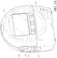
- FIG. 1illustrates a reduced pressure wound therapy system including a pump assembly according to some embodiments.
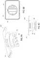
- FIG. 2Aillustrates a front view of a pump assembly connected to a canister.
- FIG. 2Billustrates an exploded view of the pump assembly and canister of FIG. 2A .
- FIG. 3illustrates a top view of a canister.
- FIG. 4illustrates a side cross-sectional view of a canister having a filter stack.
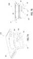
- FIG. 5is a exploded view of a filter stack.
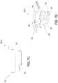
- FIG. 6Ais a cross-sectional view of a filter carrier.
- FIG. 6Bis a top view of the filter carrier of FIG. 6A .
- FIG. 6Cis a side cross-sectional view of the filter carrier of FIG. 6A .
- FIG. 7Ais a cross-sectional view of a filter carrier.
- FIG. 7Bis a side cross-sectional view of the filter carrier of FIG. 7A .
- FIG. 7Cis a side view of a filter carrier.
- FIG. 7Dis a side cross-sectional view of the filter carrier of FIG. 7C .
- FIG. 7Fis a side view of a filter carrier.
- FIG. 7Fis a side cross-sectional view of the filter carrier of FIG. 7E .
- FIG. 7Gis a pump-side view of an exit of the filter carrier of FIG. 7E .
- FIG. 7His a partial bottom view of a filter carrier.
- FIG. 7Iis a side cross-sectional view of the filter carrier of FIG. 7H .
- FIG. 8Ais a cross-sectional view of a filter carrier.
- FIG. 8Bis a side cross-sectional view of the filter carrier of FIG. 8A .
- FIG. 9is a cross-sectional view of a filter carrier.
- FIG. 10Ais a cross-sectional view of a filter carrier.
- FIG. 10Bis a side cross-sectional view of the filter carrier of FIG. 10A .
- FIG. 10Cis a top view of the guard of the filter carrier of FIG. 10A .
- FIG. 10Dis a bottom view of the base of the filter carrier of FIG. 10A .
- FIG. 10Eis a bottom view of the guard of FIG. 10C attached to the base of FIG. 10D .
- FIG. 10Fis a partial side cross-sectional view of a filter carrier.
- FIG. 10Gis a pump-side perspective view of the guard of the filter carrier of FIG. 10F .
- FIG. 10His a canister-side perspective view of the base of the filter carrier of FIG. 10F .
- FIG. 10Iis a canister-side perspective view of the guard of FIG. 10G attached to the base of FIG. 10H .
- FIG. 11Ais a cross-sectional view of a filter carrier.
- FIG. 11Bis a side cross-sectional view of the filter carrier of FIG. 11A .
- FIG. 11Cis a top view of the guard of the filter carder of FIG. 11A .
- FIG. 11Dis a bottom view of the base of the filter carrier of FIG. 11A .
- FIG. 12Ais a cross-sectional view of a filter carrier.
- FIG. 12Bis a bottom view of the filter carrier of FIG. 12A .
- FIG. 13Ais a bottom view of a filter carrier.
- FIG. 13Bis a side cross-sectional view of the filter carrier of FIG. 13A .
- FIG. 13Cis a side view of the filter carrier of FIG. 13A .
- FIG. 14Ais a bottom view of a filter carrier.
- FIG. 14Bis a side cross-sectional view of the filter carrier of FIG. 14A .
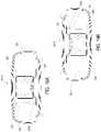
- FIG. 14Cis a cross-sectional view of a canister on its back.
- FIG. 14Dis a cross-sectional view of a canister in an upright orientation.
- FIG. 15Ais a side cross-sectional view of a filter carrier and canister.
- FIG. 15Bis a top cross-sectional view of the filter carrier and canister of FIG. 15A .
- FIG. 16Ais a side cross-sectional view of a filter carrier and canister.
- FIG. 16Bis a top cross-sectional view of the filter carrier and canister of FIG. 16A .
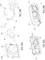
- FIG. 17Ais a side cross-sectional view of a filter carrier and canister.
- FIG. 17Bis a bottom view of the filter carrier of FIG. 17A when the canister is oriented on its back.
- FIG. 17Cis a partial front cross-sectional view of a filter carrier and canister.
- FIG. 17Dis a front cross-sectional view of the filter carrier of FIG. 17C .
- FIG. 18Ais a side cross-sectional view of a filter carrier and canister.
- FIG. 18Bis a front cross-sectional view of the filter carrier and canister of FIG. 18A .
- FIG. 18Cis a bottom view of the filter carrier of FIG. 18A when the canister is oriented on its back.
- FIG. 19Ais a cross-sectional view of the filter carrier of FIG. 18A when the canister is resting on its back.
- FIG. 19Bis a cross-sectional view of the filter caner of FIG. 18A when the canister is resting on its front.
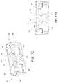
- FIG. 20Ais a bottom view of a filter carrier.
- FIG. 20Bis a side cross-sectional view of the filter carrier of FIG. 20A .
- FIG. 20Cis a cross-sectional view of the filter carrier of FIG. 20A when the canister is upright.
- FIG. 20Dis a cross-sectional view of the filter carrier of FIG. 20A when the canister is resting on its back.
- Embodiments disclosed hereinrelate to systems and methods of treating a wound with reduced pressure.
- reduced or negative pressure levelssuch as ⁇ X mmHg
- ⁇ X mmHgrepresent pressure levels relative to normal ambient atmospheric pressure, which can correspond to 760 mmHg (or 1 atm, 29.93 inHg, 101.325 kPa, 14.696 psi, etc.).
- a negative pressure value of ⁇ X mmHgreflects absolute pressure that is X mmHg below, for example, 760 mmHg or, in other words, an absolute pressure of (760 ⁇ X) mmHg.
- negative pressure that is “less” or “smaller” than X mmHgcorresponds to pressure that is closer to atmospheric pressure (e.g., ⁇ 40 mmHg is less than ⁇ 60 mmHg).
- Negative pressure that is “more” or “greater” than ⁇ X mmHgcorresponds to pressure that is farther from atmospheric pressure (e.g., ⁇ 80 mmHg is more than ⁇ 60 mmHg).
- local ambient atmospheric pressureis used as a reference point, and such local atmospheric pressure may not necessarily be, for example, 760 mmHg.
- Embodiments of the present disclosureare generally applicable to use in topical negative pressure (TNP) or reduced pressure therapy systems.
- TNPtopical negative pressure
- negative pressure wound therapyassists in the closure and healing of many forms of “hard to heal” wounds by reducing tissue edema, encouraging blood flow and granular tissue formation, or removing excess exudate and can reduce bacterial load (and thus infection risk).
- the therapyallows for less disturbance of a wound leading to more rapid healing.
- TNP therapy systemscan also assist hi the healing of surgically closed wounds by removing fluid.
- TNP therapyhelps to stabilize the tissue in the apposed position of closure.
- a further beneficial use of TNP therapycan be found in grafts and flaps where removal of excess fluid is important and close proximity of the graft to tissue is required in order to ensure tissue viability.
- FIG. 1illustrates an embodiment of a negative or reduced pressure wound treatment (or TNP) system 100 comprising a wound filler 130 placed inside a wound cavity 110 , the wound cavity sealed by a wound cover 120 .
- the wound filler 130 in combination with the wound cover 120can be referred to as wound dressing.
- a single or multi-lumen tube or conduit 140connects the wound cover 120 with a pump assembly 150 configured to supply reduced pressure.
- the conduit 140can be in fluidic communication with the wound cavity 110 .
- the pump assemblycan be configured to include or support a canister 160 .
- any of the pump assembly embodiments disclosed hereincan be a canisterless pump assembly (meaning that exudate is collected in the wound dressing or is transferred via tube 140 for collection to another location).
- the reduced pressure wound therapy system 100may operate with a canister 160 .
- the negative pressure wound therapy system 100may operate with a foam or gauze RENASYSTM dressing sold by Smith & Nephew or any other suitable dressing.
- the canister 160may be removed and the negative pressure wound therapy system 100 may operate with an absorbent dressing, such as the PICOTM dressing sold by Smith & Nephew or any other suitable dressing that retains the wound exudate within the dressing.
- an absorbent dressingsuch as the PICOTM dressing sold by Smith & Nephew or any other suitable dressing that retains the wound exudate within the dressing.
- Further details of absorbent dressings such as the PICOTM dressingare found in U.S. Pat. No. 9,061,095, filed on Apr. 21, 2011, and incorporated in its entirety by reference herein.
- any of the pump assembly embodimentscan be mounted to or supported by the dressing, or adjacent to the dressing.
- the wound filler 130can be any suitable type, such as hydrophilic or hydrophobic foam, gauze, inflatable bag, and so on.
- the wound filler 130can be conformable to the wound cavity 110 such that it substantially fills the cavity.
- the wound cover 120can provide a substantially fluid impermeable seal over the wound cavity 110 .
- the wound cover 120has a top side and a bottom side, and the bottom side adhesively (or in any other suitable manner) seals with wound cavity 110 .
- the conduit 140 or any other conduit disclosed hereincan be formed from polyurethane, PVC, nylon, polyethylene, silicone, or any other suitable material.
- the wound cover 120can have a port (not shown) configured to receive an end of the conduit 140 .
- the conduit 140can otherwise pass through and/or under the wound cover 120 to supply reduced pressure to the wound cavity 110 so as to maintain a desired level of reduced pressure in the wound cavity.
- the conduit 140can be any suitable article configured to provide at least a substantially sealed fluid flow pathway between the pump assembly 150 and the wound cover 120 , so as to supply the reduced pressure provided by the pump assembly 150 to the wound cavity 110 .
- the wound cover 120 and the wound filler 130can be provided as a single article or an integrated single unit. In some embodiments, no wound filler is provided and the wound cover by itself may be considered the wound dressing.
- the wound dressingmay then be connected, via the conduit 140 , to a source of negative pressure, such as the pump assembly 150 .
- the pump assembly 150can be miniaturized and portable, although larger conventional pumps such can also be used.
- the wound cover 120can be located over a wound site to be treated.
- the wound cover 120can form a substantially sealed cavity or enclosure over the wound site.
- the wound cover 120can be configured to have a film having a high water vapour permeability to enable the evaporation of surplus fluid, and can have a superabsorbing material contained therein to safely absorb wound exudate.
- a woundit is to be understood that the term wound is to be broadly construed and encompasses open and closed wounds in which skin is torn, cut or punctured or where trauma causes a contusion, or any other surficial or other conditions or imperfections on the skin of a patient or otherwise that benefit from reduced pressure treatment.
- a woundis thus broadly defined as any damaged region of tissue where fluid may or may not be produced.
- woundsinclude, but are not limited to, acute wounds, chronic wounds, surgical incisions and other incisions, subacute and dehisced wounds, traumatic wounds, flaps and skin grafts, lacerations, abrasions, contusions, burns, diabetic ulcers, pressure ulcers, stoma, surgical wounds, trauma and venous ulcers or the like.
- the components of the TNP system described hereincan be particularly suited for incisional wounds that exude a small amount of wound exudate.
- Some embodiments of the systemare designed to operate without the use of an exudate canister 160 . Some embodiments can be configured to support an exudate canister 160 . In some embodiments, configuring the pump assembly 150 and tubing 140 so that the tubing 140 can be quickly and easily removed from the pump assembly 150 can facilitate or improve the process of dressing or pump changes, if necessary. Any of the pump embodiments disclosed herein can be configured to have any suitable connection between the tubing 140 and the pump 150 .
- the pump assembly 150can be configured to deliver negative pressure of approximately ⁇ 80 mmHg, or between about ⁇ 20 mmHg and ⁇ 200 mmHg. Note that these pressures are relative to normal ambient atmospheric pressure thus, ⁇ 200 mmHg would be about 560 mmHg in practical terms.
- the pressure rangecan be between about ⁇ 40 mmHg and ⁇ 150 mmHg. Alternatively a pressure range of up to ⁇ 75 mmHg, up to ⁇ 80 mmHg or over ⁇ 80 mmHg can be used. Also in other embodiments a pressure range of below ⁇ 75 mmHg can be used. Alternatively a pressure range of over approximately ⁇ 100 mmHg, or even 150 mmHg, can be supplied by the pump assembly 150 .
- the pump assembly 150is configured to provide continuous or intermittent negative pressure therapy.
- Continuous therapycan be delivered at above ⁇ 25 mmHg, ⁇ 25 mmHg, ⁇ 40 mmHg, ⁇ 50 mmHg, ⁇ 60 mmHg, ⁇ 70 mmHg, ⁇ 80 mmHg, ⁇ 90 mmHg, ⁇ 100 mmHg, ⁇ 120 mmHg, ⁇ 140 mmHg, ⁇ 160 mmHg, ⁇ 180 mmHg, ⁇ 200 mmHg, or below ⁇ 200 mmHg.
- Intermittent therapycan be delivered between low and high negative pressure set points.
- Low set pointcan be set at above 0 mmHg, 0 mmHg, ⁇ 25 mmHg, ⁇ 40 mmHg, ⁇ 50 mmHg, ⁇ 60 mmHg, ⁇ 70 mmHg, ⁇ 80 mmHg, ⁇ 90 mmHg, ⁇ 100 mmHg, ⁇ 120 mmHg, ⁇ 140 mmHg, ⁇ 160 mmHg, ⁇ 180 mmHg, or below ⁇ 180 mmHg.
- High set pointcan be set at above ⁇ 25 mmHg, ⁇ 40 mmHg, ⁇ 50 mmHg, ⁇ 60 mmHg, ⁇ 70 mmHg, ⁇ 80 mmHg, ⁇ 90 mmHg, ⁇ 100 mmHg, ⁇ 120 mmHg, ⁇ 140 mmHg, ⁇ 160 mmHg, ⁇ 180 mmHg, ⁇ 200 mmHg, or below ⁇ 200 mmHg.
- negative pressure at low set pointcan be delivered for a first time duration, and upon expiration of the first time duration, negative pressure at high set point can be delivered for a second time duration. Upon expiration of the second time duration, negative pressure at low set point can be delivered.
- the first and second time durationscan be same or different values.
- the first and second durationscan be selected from the following range: less than 2 minutes, 2 minutes, 3 minutes, 4 minutes, 6 minutes, 8 minutes, 10 minutes, or greater than 10 minutes.
- switching between low and high set points and vice versacan be performed according to a step waveform, square waveform, sinusoidal waveform, and the like.
- the wound filler 130is inserted into the wound cavity 110 and wound cover 120 is placed so as to seal the wound cavity 110 .
- the pump assembly 150provides a source of a negative pressure to the wound cover 120 , which is transmitted to the wound cavity 110 via the wound filler 130 .
- Fluide.g., wound exudate
- Fluidis drawn through the conduit 140 , and can be stored in a canister 160 .
- fluidis absorbed by the wound filler 130 or one or more absorbent layers (not shown).
- Wound dressingsthat may be utilized with the pump assembly and other embodiments of the present application include Renasys-F, Renasys-G, Renasys AB, and Pico Dressings available from Smith &. Nephew. Further description of such wound dressings and other components of a negative pressure wound therapy system that may be used with the pump assembly and other embodiments of the present application are found in U.S. Patent Publication Nos. 2012/0116334, 2011/0213287, 2011/0282309, 2012/0136325 and U.S. patent application Ser. No. 13/287,897, which are assigned to the assignee of present application and are incorporated by reference in their entirety. In other embodiments, other suitable wound dressings can be utilized.
- FIG. 2Aillustrates a front view of a pump assembly 230 and canister 220 according to some embodiments.
- the pump assembly 230can include one or more latch recesses 222 formed in the cover. In the illustrated embodiment, two latch recesses 222 can be formed on the sides of the pump assembly 230 .
- the latch recesses 222can be configured to allow attachment and detachment of the canister 220 using one or more canister latches 221 .
- the pump assembly 230comprises an air outlet 224 for allowing air removed from the wound cavity 110 to escape. Air entering the pump assembly 230 can be passed through one or more suitable filters (described below, such as in FIG.
- the pump assembly 230can include one or more strap mounts 226 for connecting a carry strap to the pump assembly 230 or for attaching a cradle. In the illustrated embodiment, two strap mounts 226 can be formed on the sides of the pump assembly 230 . Further details of pump assembly are found in U.S. patent application Ser. No. 14/210,062, entitled SYSTEMS AND METHODS FOR APPLYING REDUCED PRESSURE THERAPY, filed on Jul. 3, 2014, and incorporated in its entirety by reference herein.
- FIG. 2Bshows a partial bottom view of the pump assembly 230 separated from the canister 220 according to some embodiments.
- the pump assembly 230can include a vacuum attachment or connector 252 through which a vacuum pump communicates negative pressure to the canister 220 .
- FIG. 3shows a canister 220 A similar to the canister 220 except as described differently below.
- the features of the canister 220 Acan be combined or included with the canister 220 or any other embodiment discussed herein.
- the canister 220 Ahas a capacity of approximately 300 mL.
- the canister 220 Acan have a capacity other than 300 mL (e.g., 800 mL).
- the canister 220 Acan include a bulkhead 240 .
- the bulkhead 240can include a vacuum attachment or connector 242 through which the canister receives vacuum communicated by the pump assembly 230 .
- the connector 242is configured to be connected to or mated with the connector 252 of the pump assembly 230 .
- FIG. 4illustrates a cross-sectional side view of a canister 220 B similar to the canister 220 A except as described differently below.
- the features of the canister 220 Bcan be combined or included with the canister 220 A or any other embodiment discussed herein.
- the bulkhead 240includes a cap portion 244 and a base portion 246 .
- the canistercan include a receptacle 248 .
- the receptacle 248can be adapted to receive wound exudate that is aspirated from the wound when a negative pressure is applied to the canister 220 B through the connector 242 by the pump assembly 230 .
- the bulkhead 240can be assembled onto the receptacle 248 , as shown in FIG. 4 .
- the base portion 246can be interposed between the receptacle 248 and the cap portion 246 when the bulkhead 240 is assembled onto the receptacle 248 .
- the canister 220 Bcan include a canister filter stack 300 .
- the canister filter stack 300can be attached to the base portion 246 of the bulkhead 240 .
- the canister filter stack 300can be positioned near an inflow port 254 through which wound exudate can be drawn into the receptacle 248 when a negative pressure is applied to the canister 220 B.
- the canister filter stack 300 and the inflow port 254are both located along a sagittal plane that passes through the back surface 228 and the front surface 229 of the canister 220 B.
- the canister filter stack 300 and the inflow port 254can be positioned away from one another.
- the filter stack 300can be positioned near a corner formed by the right side and the front surface 229 of the canister 220 B while the inflow port 254 is located near a corner formed by the left side and the rear surface 228 of the canister 220 B.
- the canister stack 300can be positioned away from the inflow port 254 to avoid frothing at the inflow port 254 from entering the filter stack 300 .
- FIG. 5illustrates an embodiment of a canister filter stack 300 A similar to the canister filter stack 300 except as described differently below.
- the features of the canister filter stack 300 Acan be combined or included with the canister filter stack 300 or any other embodiment discussed herein.
- the canister filter stack 300 Acan include a filter carrier 302 , a shutoff 304 , an odor filter 306 , and an antibacterial filter 308 .
- the shutoff 304 , the odor filter 306 , and the antibacterial filter 308can be arranged in any order.
- the odor filter 306can be disposed between the shutoff 304 and the antibacterial filter 308 , as shown in FIG.
- the shutoff 304can be disposed between the odor filter 306 and the antibacterial filter 308 .
- the shutoff 304can operate to stop suction when the canister 220 becomes full such that canister overfill is prevented.
- the shutoff 304can be formed out of hydrophilic material.
- the odor filter 306can comprise material that absorbs, reduces or eliminates odor.
- such materialcan be active carbon, activated charcoal, or the like.
- the materialcan be hydrophobic.
- the devicecan use a catalytic-type converter to oxidize odors.
- the odor filter 306can include materials that chemically neutralize odors.
- the odor filter 306can include anionic, cationic, acid, or basic chemically-modified polymers that chemically react with odors. These materials can work well in the moist or humid conditions that would be present in the wound.
- the antibacterial filter 308can inhibit or eliminate the growth of microorganisms.
- the components of the filter stack 300can be arranged in any suitable order.
- the odor filter 306can be integrated into the shutoff 304 as an additive to the material of the shutoff 304 or as a layer formed on the material of the shutoff 304 .
- the filter stack 300is placed in the canister 220 . In some embodiments, the filter stack 300 is placed between the canister 220 and the pump assembly 230 . In some embodiments, the filter stack 300 is placed in the pump assembly 230 .
- the filter carrier 302can be adapted to house one or more of the shutoff 304 , the odor filter 306 , and the antibacterial filter 308 .
- the filter carrier 302can include features that reduce or prevent liquid inside the canister 220 from contacting one or more of the shutoff 304 , the odor filter 306 , and the antibacterial filter 308 .
- the filter carrier 302can be arranged to mitigate fluids within the canister 220 from splashing onto the shutoff 304 .
- the filter carrier 302can be arranged to allow air to traverse from the canister 220 to the pump assembly 230 , thereby allowing the pump assembly 230 to create a negative pressure within the canister 220 .
- the filter carrier 302includes only one hole for air to traverse to the pump.
- the filter carrier 302can be arranged to ensure continual pump operation in one or more likely orientations of the canister 220 .
- the filter carrier 302can be configured to mitigate issues related to blockages of narrow pathways, as described further below.
- the filter carrier 302is arranged to mitigate large pressure drops that can significantly increase down times of the pump.
- the filter carrier 302can be arranged to provide a flow path between the canister and the pump. The flow path can allow the pump assembly 230 to evacuate air from the canister 220 , thereby creating a negative pressure within the canister 220 that can draw into the canister 220 wound exudate from the wound dressing.
- the filter carrier 302can include features that make the flow path between the canister 220 and the pump 230 more easily navigable by gas (e.g., air) than by liquid (e.g., wound exudate).
- the filter carrier 302can include features that prevent wound exudate from passing across the filter carrier 302 and reaching the pump assembly 230 or wetting the filters (e.g., the shutoff 304 , the odor filter 306 , and the antibacterial filter 308 ).
- FIGS. 6A-6Cshow a filter carrier 302 A similar to the filter carrier 302 except as described differently below.
- the features of the filter carrier 302 Acan be combined or included with the filter carrier 302 or any other embodiment discussed herein.
- the filter carrier 302 Acan have a central portion 320 that extends from a peripheral portion 322 .
- the filter carrier 302 Acan be oriented so that the peripheral portion 322 is attached to the bulkhead 240 with the central portion 320 extending toward the canister 220 , as shown in FIG. 4 .
- the central portion 320can include a plurality of upper fins 324 and a plurality of lower fins 326 , as shown in FIG. 6A .
- the upper fins 324can be disposed between the lower fins 326 and one or more of the shutoff 304 , the odor filter 306 , and the antibacterial filter 308 .
- the lower fins 326can be disposed between the upper fins 324 and the wound exudate that has been aspirated into the canister 220 , as described above.
- the upper fins 324can interdigitate with the lower fins 326 , as shown in FIG. 6B .
- the upper fins 324 and the lower fins 326can be sized so that a gap 328 is visible between the upper fins 324 and the lower fins 326 when the fins 324 , 326 are viewed from the top (e.g., a front view of the surface of the carrier 302 A that faces the pump assembly 230 ).
- the fins 324 , 326can be arranged so that the gap 328 between the fins forms a single, continuous, serpentine opening (as indicated by the white line in FIG. 6B ).
- the gap 328can provide a pathway for air to traverse from the interior space of the canister 220 to the connector 242 (shown in FIG. 4 ), thereby allowing the pump assembly 230 to create a negative pressure inside the canister 220 .
- the fins 324 , 326can create jetty-like structures that prevent wound exudate within the canister 220 from splashing across the fins 324 , 326 .
- the fins 324 , 326can be U-shaped.
- the open portion of the U-shaped upper fins 324can face the canister 220 .
- the open portion of the U-shaped lower fins 326can face the pump assembly 230 .
- the U-shaped fins 324 , 326can increase the structural rigidity to the filter carrier 302 A.
- the U-shaped fins 324 , 326can guide liquid back into the canister 220 .
- the fins 324 , 326can allow air to pass by the fins 324 , 326 , while preventing or inhibiting liquid from passing by the fins 324 , 326 .
- the fins 324 , 326can prevent wound exudate within the canister 320 from contacting one or more of the shutoff 304 , the odor filter 306 , and the antibacterial filter 308 .
- FIGS. 7A and 7Billustrate a filter carrier 302 B similar to the filter carrier 302 A except as described differently below.
- the features of the filter carrier 302 Bcan be combined or included with the filter carrier 302 A or any other embodiment discussed herein.
- the peripheral portion 322can be disposed closer to the pump assembly 230 than is the central portion 320 when the filter carrier 302 B is arranged for use in the TNP system.
- the central portion 320 of the filter carrier 302 Bcan extend from the peripheral portion 322 into the interior space of the canister 220 .
- the filter carrier 302 Bcan have a passageway 330 that provides a flow path between the connector 242 (shown in FIG. 4 ) and the receptacle 248 of the canister 220 .
- the passageway 330can provide a flow path for the pump assembly 230 to draw air out of the canister 220 , thereby creating a negative pressure inside the canister 220 , as described above.
- the passageway 330can have an entrance 332 through which air inside the canister 220 can enter into the passageway 330 when the pump assembly 230 applies a negative pressure to draw air out of the canister 220 .
- the passageway 330can have an exit 334 through which air can exit the passageway 330 to flow toward the pump assembly 230 when the pump assembly 230 applies a negative pressure to draw air out of the canister 220 .
- the passageway 330can be arranged to provide a tortuous path that is easily navigable by gas (e.g., air) but not by liquid (e.g., wound exudate).
- the central portion 320can include a barrier 336 .
- the barrier 336can extend from the pump-side surface of the central portion 320 in an axial direction toward the pump assembly 230 .
- the barrier 336can block or inhibit liquid from flowing across the pump-side surface of the central portion 320 .
- the filter carrier 302 Bcan include a top ledge 338 that extends radially inward from an inner surface of the filter carrier 302 B toward the barrier 336 . A portion of the ledge 338 can join with the barrier 336 , as shown in FIG. 7A .
- a portion of the ledge 338does not extend to join with the barrier 336 , thereby creating a stepped passageway 330 that allows air to flow from the canister 220 toward the pump assembly 230 when the pump assembly 230 applies a negative pressure to draw air out of the canister 220 .
- the stepped passageway 330is not easily navigable by liquid. Liquid that enters the passageway 330 through the entrance 332 cannot easily flow up the barrier 336 to reach the exit 334 .
- the passageway 330can be angled toward the entrance 332 to facilitate draining back into the canister 220 any liquid that enters the passageway 330 . As shown in FIG.
- the entrance 332 of the passageway 330can face radially outward, thereby reducing the likelihood that the wound exudate within the canister 220 will enter into the passageway 330 .
- the entrance 332can extend circumferentially around a longitudinal axis of the filter carrier 302 B that passes through a center of the central portion 320 .
- the entrance 332has a circumferential extension of about: 45 degree, 90 degrees, 180 degrees, 270 degrees, and values therebetween.
- FIGS. 7C and 7Dillustrate a filter carrier 302 B′ similar to the filter carrier 302 B except as described differently below.
- the features of the filter carrier 302 B′can be combined or included with the filter carrier 302 B or any other embodiment discussed herein.
- the pump-side surface of the central portion 320can be substantially co-planar with the pump-side opening of the exit 334 .
- the pump-side surface of the central portion 320slopes toward the exit 334 so that any liquid that flows onto the pump-side surface of the central portion 320 will tend to drain back toward the exit 334 to enter the passageway 330 .
- the pump-side surface of the passageway 330can be sloped toward the entrance 332 so that liquid in the passageway tends to drain back through the entrance 332 to enter the canister 220 .
- FIGS. 7E and 7Fillustrate a filter carrier 302 B′′ similar to the filter carrier 302 B′ except as described differently below.
- the features of the filter carrier 302 B′′can be combined or included with the filter carrier 302 B′ or any other embodiment discussed herein.
- the central portion 320can extend away from the peripheral portion 322 along a longitudinal axis 10 .
- the filter carrier 302 B′′can have an entrance 332 that is disposed on an outer longitudinal surface 331 of the filter carrier 302 B′′.
- the entrance 332circumferentially surrounds the longitudinal axis 10 by more than 180 degrees.
- the entrance 332has a circumferential extension of about: 45 degree, 90 degrees, 180 degrees, 270 degrees, and values therebetween.
- FIG. 7Gshows a pump-side front view of the filter carrier 302 B′′, viewed along the longitudinal axis 10 .
- the entrance 332extends along the outer longitudinal surface 331 counter-clockwise from point A to point B.
- the entrance 332has a circumferential extension of about 270 degrees.
- the ledge 338can extend from an inner longitudinal surface 333 of the filter carrier 302 B′′.
- the central portion 320can include a distal-most central portion 321 and an intermediate central portion 323 , with the intermediate central portion 323 being disposed longitudinally between the peripheral portion 322 and the distal-most central portion 321 , as shown in FIG. 7F .
- the harrier 336connects the distal-most central portion 321 to the intermediate central portion 323 .
- a portion of the ledge 338extends between the barrier 336 and the exit 334 , thereby forming an overhang 335 , as shown in FIG. 7F .
- the overhang 335can prevent or reduce liquid from splashing through the exit 334 when the liquid contacts the barrier 336 . Liquid that enters the entrance 332 and flows along the distal-most central portion 321 may splash upward through the exit 334 when the liquid strikes the barrier 336 .
- the overhang 335can be sized so that such splashing liquid strikes canister-side surface of the overhang 335 , thereby blocking the liquid from passing through the exit 334 and wetting any elements housed within the filter carrier 302 B′′ (e.g., the shutoff 304 , the odor filter 306 , the antibacterial filter 308 ).
- FIGS. 7H and 7Iillustrate a filter carrier 302 B′′′ similar to the filter carrier 302 B′′ except as described differently below.
- the features of the filter carrier 302 B′′′can be combined or included with the filter carrier 302 B′′ or any other embodiment discussed herein.
- the entrance 332nearly entirely circumferentially surrounds the longitudinal axis 10 .
- the central portion 320includes a plug portion 337 and a dock portion 339 .
- a strut 341connects the plug portion 337 to the dock portion 339 , as shown in FIG. 7I .
- the plug portion 337is connected to the dock portion 339 by only one strut 341 .
- the entrance 332extends circumferentially around the entire periphery of the central portion 320 except for the portion of the periphery that is occupied by the strut 341 .
- the plug portion 337is connected to the dock portion 339 by more than one circumferentially-spaced-apart strut 341 .
- the number of struts 341 that connect the plug portion 337 to the dock portion 339can be one, two, three, or more than three.
- the flow path 330 of the filter carrier 302 B′′′is formed by the gap between the plug portion 337 and the dock portion 339 .
- the flow path 330is configured to be more easily navigable by gas (e.g., air) than by liquid (e.g., wound exudate).
- gase.g., air
- liquide.g., wound exudate
- the plug portion 337can have a brim 343 that is disposed radially outward of a crown 347 .
- the crown 347can extend longitudinally from the brim 343 along the longitudinal axis 10 in the pump-side direction, as shown in FIG. 7I .
- the crown 347can have a crown face 351 , which is the pump-side surface of the crown 347 , as indicated in FIG. 7I .
- the crown 347has a crown outer sidewall 349 that circumferentially surrounds the outer periphery of the crown face 351 .
- the crown outer sidewall 349faces the entrance 332 .
- the dock portion 339can have a dock face 353 , which is the canister-side surface of the dock portion 339 , as shown in FIG. 7I .
- the crown face 351is substantially longitudinally aligned with the dock face 353 .
- the pump-side aspect of the crown 347extends up to, but not past, the canister-side aspect of the dock portion 339 .
- the dock face 353is longitudinally disposed between the crown face 351 and the brim 343 of the plug portion 337 .
- the pump-side aspect of the plug portion 337extends into the dock portion 339 .
- the crown face 351is longitudinally disposed between the dock face 353 of the dock portion 339 and the brim 343 of the plug portion 337 .
- the stint 341 connecting the plug portion 337 to the dock portion 339longitudinally spans a gap formed between the pump-side-most aspect of the plug portion 337 and the canister-side-most aspect of the dock portion 339 .
- the brim 343can have a brim outer sidewall 355
- the dock portion 339can have a dock outer sidewall 357 .
- the brim outer sidewall 355has an outer diameter that is substantially equal to that of the dock outer sidewall 357 .
- the brim outer sidewall 355has an outer diameter that is larger than that of the dock outer sidewall 357 .
- the brim outer sidewall 355has an outer diameter that is smaller than that of the dock outer sidewall 357 .
- the dock portion 339can have a dock inner sidewall 359 .
- the dock face 353extends between the dock inner sidewall 359 and the dock outer sidewall 357 .
- the dock face 353can radially overlap with the brim 343 , forming a portion of the flow path 330 that runs substantially perpendicular to the longitudinal axis 10 .
- the radial extent of the dock face 353is substantially coextensive with the radial extent of the brim 343 .
- the brim 343extends radially beyond the dock face 353 .
- the dock face 353extends radially beyond the brim 343 , as described previously above.
- FIGS. 8A and 8Billustrate a filter carrier 302 C similar to the filter carrier 302 B except as described differently below.
- the features of the filter carrier 302 Ccan be combined or included with the filter carrier 302 B or any other embodiment discussed herein.
- the filter carrier 302 Ccan have two spaced-apart walls 336 that extend from the pump-side surface of the central portion 320 in an axial direction toward the pump assembly 230 .
- the filter carrier 302 Ccan have two opposing stepped passageways 330 that extend radially inward to the walls 336 , where the passageways 330 and walls or barriers 336 function as described above with regard to the filter carrier 302 B shown in FIG. 7A .
- FIG. 9shows a filter carrier 302 D similar to the filter carrier 302 C except as described differently below.
- the features of the filter carrier 302 Dcan be combined or included with the filter carder 302 C or any other embodiment discussed herein.
- the filter carrier 302 Dcan have two opposing stepped passageways 330 that extend radially inward to a single wall or harrier 336 , where the passageways 330 and wall or barrier 336 function as described above with regard to the filter carrier 302 C.
- FIGS. 10A-10Eillustrate a filter carrier 302 E similar to the filter carrier 302 D except as described differently below.
- the features of the filter carrier 302 Ecan be combined or included with the filter carrier 302 D or any other embodiment discussed herein.
- the filter carrier 302 Ecan include features that form a labyrinth of concentric rings, thereby creating a flow path that is more easily navigable by gas air) than by liquid (e.g., wound exudate).
- the filter carrier 302 Ecan include a central opening 340 that is circumferentially surrounded by an inner rim 342 , as shown in FIG. 10A .
- An outer rim 343can circumferentially surround the inner rim 342 .
- a shelf 345can connect the outer rim 343 to the inner rim 342 , as shown in FIG. 10A .
- the filter carrier 302 Ecan include a guard 344 that is positioned substantially perpendicular to a longitudinal axis of the central opening 340 .
- the guard 344can be disposed between the central opening 340 and the interior space of the canister 220 along the longitudinal axis of the central opening 340 , as shown in FIG. 10A .
- the guard 344can have a flange 346 that circumferentially surrounds the inner rim 342 , as shown in FIG. 10A .
- a section 348 of the flange 346can have a reduced height compared to adjacent portions of the flange 346 , as indicated in FIGS. 10B and 10C .
- the flange 346can be attached to the shelf 345 (e.g., by an adhesive). In some embodiments, the flange 346 is ultrasonically welded to the shelf 345 .
- the inner rim 342can have an area of reduced height that forms a notch 350 , as shown in FIG. 10D .
- the guard 344can be attached to the shelf 345 so that the section 348 is disposed circumferentially across from the notch 350 , as indicated in FIG. 10B .
- the guard 344can include one or more hurdles or protrusions 352 that extend radially inward from the flange 346 .
- the hurdles 352can serve as a barrier that impedes liquid flow along the pump-side surface of the guard 344 when the guard 344 is attached as shown in FIG. 10A to the shelf 345 .
- the hurdles or protrusions 352can span the gap between the flange 346 and the inner rim 342 when the guard 344 is attached to the shelf 345 .
- One or more of the hurdles 352can have a height that is smaller than the height of the flange 346 , creating a gap between the hurdle 352 and the shelf 345 .
- Liquide.g., wound exudate
- gravity forceswhich are substantially parallel with the height of the hurdle 352 , resist liquid flowing over the hurdle 352 .
- the earner 302 Eprovides a flow path 330 between the central opening 340 and the interior space of the canister 220 ,
- the entrance 332 of the flow path 330is the gap between the section 348 and the shelf 345 .
- the exit 334 of the flow path 330is the gap between the notch 350 and the guard 344 .
- the entrance 332is connected to the exit 334 by a channel 354 that is bounded laterally by the inner rim 342 and the flange 348 and bounded axially by the shelf 345 and the guard 344 , as shown in FIG. 10A .
- the channel 354can include one or more hurdles 352 that span between the inner rim 342 and the flange 346 .
- the hurdles 352may extend only partially across the space between the guard 344 and the shelf 345 , leaving a gap that is more easily navigable by gas (e.g., air) than by liquid (e.g., wound exudate), as described previously.
- FIGS. 10F-10Iillustrate a filter carrier 302 E′ similar to the filter carrier 302 E except as described differently below.
- the features of the filter carrier 302 E′can be combined or included with the filter carrier 302 E or any other embodiment discussed herein.
- the height of the inner rim 342 and the flange 346can be elongated along the longitudinal axis of the central opening 340 to form deep cavities in the flow path 330 between the guard 344 and the shelf 345 , as shown in FIG. 10F .
- the deep cavitiescan allow for better airflow through the flow path 330 .
- the filter carrier 302 E′can form a two-part labyrinth of concentric rings, as described below.
- the outer rim 343can have a height defined by the extent to which the outer rim 343 extends longitudinally away from the peripheral portion 322 . As shown in FIG. 10H , the height of the outer rim 343 can be reduced in a region to form a pass 361 . As discussed above, a section 348 of the flange 346 can have a reduced height compared to adjacent portions of the flange 346 , as shown in FIG. 10G .
- the filter carrier 302 B′can be arranged so that the pass 361 is circumferentially spaced apart from the section 348 by about 180 degrees, as shown in FIG. 10F .
- the canister-most surface of the guard 344can be longitudinally disposed between the canister-most surface of the pass 361 and the canister-most surface of the remaining portion of the outer rim 343 .
- the remaining portion of the outer rim 343can protect against liquid (e.g., wound exudate) from splashing past the section 348 .
- the filter carrier 302 E′is adapted to allow gas (e.g., air) to flow past the guard 344 to access the central opening 340 , while inhibiting or preventing liquid (e.g., wound exudate) from flowing past the guard 344 to reach the central opening 340 .
- the guard 344can include a pair of spaced apart walls that form an inner corral 363 therebetween.
- the inner rim 342can seat into the inner corral 363 when the filter carrier 302 E′ is assembled, as shown in FIG. 10F .
- the canister-side surface of the shelf 345can include a pair of spaced apart walls that form an outer corral 365 therebetween.
- the flange 346can seat into the outer corral 365 when the filter carrier 302 E′ is assembled.
- the guard 344can be secured to the shelf 345 and/or to the inner rim 342 by adhesive, ultrasonic welding, or other means known in the art.
- the guard 344can include one or more hurdles 352 that impede or block the flow of liquid toward the central opening 340 , as discussed above with regard to filter carrier 302 E.
- FIG. 10Ishows a bottom view of the filter carrier 302 E′.
- the pass 361is visible in FIG. 10I , while the section 348 is hidden from view by virtue of being circumferentially spaced apart from the pass 361 by about 180 degrees.
- the section 348faces away from the pass 362 and toward the remaining portion of the outer rim 343 .
- FIGS. 11A-11Dillustrate a filter carrier 302 F similar to the filter carrier 302 E except as described differently below.
- the features of the filter carrier 302 Fcan be combined or included with the filter carrier 302 E or any other embodiment discussed herein.
- the filter carrier 302 Fcan have a base 360 that is attached to a guard 344 .
- a spiral-shaped harrier 362can extend from the base 360 .
- the guard 344can have a corresponding spiral-shaped harrier 364 that interlaces with the spiral-shaped barrier 362 when the guard 344 is attached to the base 360 , as shown in FIG. 11A .
- the interlaced spiral-shaped walls 362 , 364can define a flow channel therebetween that communicates between a hole 366 , for example at or near the center of the guard 344 , and a slot 368 in the base 360 .
- Gas (e.g., air) inside the canister 220can enter the flow channel through the hole 366 and exit the flow channel through the slot 368 to flow toward the pump assembly 230 when the pump assembly 230 applies a negative pressure to the canister 220 , as described previously.
- Liquide.g., wound exudate
- FIGS. 12A and 12Billustrate a filter carrier 302 G similar to the filter carrier 302 F except as described differently below.
- the features of the filter earner 302 Gcan be combined or included with the filter carrier 302 F or any other embodiment discussed herein.
- the filter carrier 302 Gcan have a base 360 that is attached to a guard 344 .
- the base 360can have a spiral-shaped barrier 362 that interlaces with a corresponding spiral-shaped barrier 364 of the guard 344 when the guard 344 is attached to the base 360 , as shown in FIG. 12A .
- the interlaced spiral-shaped walls 362 , 364can form a flow channel therebetween that communicates between a hole 366 , for example at or near the center of the base 360 , and a slot 368 in the guard 344 .
- Gas (e.g., air) inside the canister 220can enter the flow channel through the slot 368 and exit the flow channel through the hole 366 to flow toward the pump assembly 230 when the pump assembly 230 applies a negative pressure to the canister 220 , as described previously.
- Liquide.g., wound exudate
- FIGS. 13A-13Cillustrate a filter carrier 302 H similar to the filter carrier 302 G except as described differently below.
- the features of the filter carrier 302 Hcan be combined or included with the filter carrier 302 G or any other embodiment discussed herein.
- the filter carrier 302 Hcan have a mesh 370 that is attached to the base 360 by a collar 372 .
- the mesh 370can be a tight woven metal mesh.
- the mesh 370can have a porosity that allows gas (e.g., air) to traverse the mesh 370 while preventing liquid (e.g., wound exudate) from traversing the mesh 370 .
- the mesh 370can cover an additional filter 374 that is disposed across the collar 372 and the base 360 as shown in FIG. 13B .
- the mesh 370can optionally have a convex or dome shape and can protrude away from the base 360 and the collar 370 , as shown in FIG. 13B .
- the dome shape of the mesh 370can provide air flow pathways at the periphery of the mesh 370 when the apex of the mesh 370 is submerged in or in contact with a liquid.
- FIGS. 14A-14Dillustrate a filter carrier 302 I similar to the filter carrier 302 H except as described differently below.
- the features of the filter earner 302 Ican be combined or included with the filter carrier 302 H or any other embodiment discussed herein.
- the filter carrier 302 Hcan include a pivoting snorkel 376 .
- the pivoting snorkel 376can be adapted to maintain a flow path between the canister 220 and the pump assembly 230 under different orientations of the canister 220 .
- the snorkel 376can be rotatably mounted on the base 360 of the filter carrier 302 I.
- the snorkel 376can include a counter weight 378 disposed at an end of the snorkel 376 as shown in FIG. 14B .
- the snorkel 376can have an opening 380 disposed at an end opposite of the counter weight 378 .
- the snorkel 376can have an exit 382 that communicates with the internal space of the snorkel 376 .
- the snorkel 376can provide a flow path by which air in the canister 220 can flow toward the pump assembly 230 when the pump assembly 230 applies a negative pressure. When the pump assembly 230 applies negative pressure to the canister 220 , air inside the canister 220 can enter the snorkel 376 through the opening 380 and flow out of the snorkel 376 through the exit 382 .
- FIG. 14Cshows that the snorkel 376 can pivot when the canister 220 is oriented on its back so that the opening 380 of the snorkel 376 remains within the airspace that is above the liquid inside the canister 220 .
- Gravitycan pull the counterweight 378 to drive the snorkel 376 into the vertical orientation shown in FIG. 14C when the canister 220 is oriented on its back.
- the snorkel 376will have a substantially horizontal orientation as shown in FIG. 14D .
- FIG. 14Billustrates that the snorkel 376 can house an additional filter 374 (e.g., a polytetrafluroethlyene exclusion filter).
- an additional filter 374e.g., a polytetrafluroethlyene exclusion filter
- FIGS. 15A and 15Billustrate a filter carrier 302 J similar to the filter carrier 302 I except as described differently below.
- the features of the filter carrier 302 Jcan be combined or included with the filter carrier 302 I or any other embodiment discussed herein.
- the filter carrier 302 Jcan form a unitary structure with the base portion 246 of the bulkhead 240 , as shown in FIG. 15A .
- the filter carrier 302 Jcan include one or more top baffles 384 that extend from the canister-side surface of the base portion 246 .
- the one or more top baffles 384can interlace with one or more corresponding bottom baffles 386 that extend from the interior surface of the canister 220 .
- the top baffles 384can extend only partially across the span between the interior surface of the canister 220 and the pump-side surface of the base portion 246 .
- the bottom baffles 386can extend only partially across the span between the pump-side surface of the base portion 246 and the interior surface of the canister 220 .
- the interlacing baffles 384 , 386can provide a tortuous flow path between the interlacing walls of the baffles 384 , 386 that allows fluid inside the canister 220 to access the central channel of the connector 242 .
- the interlacing baffles 384 , 386reduce or prevent liquid inside the canister from splashing into the central lumen of the connector 242 .
- the innermost top baffle 384can house an additional filter 374 .
- FIG. 15Billustrates that the interlacing baffles 384 , 386 can be a plurality of substantially circular baffles that are concentrically arranged. As shown in FIGS. 15A and 15B , the interlacing baffles 384 , 386 can be positioned near the inflow port 254 through which wound exudate can be drawn into the canister 220 . In the illustrated embodiment, the interlacing baffles 384 , 386 and the inflow port 254 are both located along a sagittal plane that passes through the hack surface 228 and the front surface 229 of the canister 220 .
- the interlacing baffles 384 , 386 and the inflow port 254can be positioned away from one another.
- the interlacing baffles 384 , 386can be positioned near a corner formed by the right side and the front surface 229 of the canister 220 B while the inflow port 254 is located near a corner formed by the left side and the rear surface 228 of the canister 220 .
- the interlacing baffles 384 , 386can be positioned away from the inflow port 254 to avoid frothing at the inflow port 254 from entering between the interlacing baffles 384 , 386 .
- FIGS. 16A and 16Billustrate a filter carrier 302 K similar to the filter carrier 302 J except as described differently below.
- the features of the filter carrier 302 Kcan be combined or included with the filter carrier 302 J or any other embodiment discussed herein.
- the filter carrier 302 Kcan attach to the base portion 246 of the bulkhead 240 , as shown in FIG. 16A .
- the filter carrier 302 Kcan include one or more top baffles 384 that extend from the canister-side surface of the filter carrier 302 K.
- the one or more top baffles 384can interlace with one or more corresponding bottom baffles 386 that extend from the interior surface of the canister 220 .
- the top baffles 384can extend only partially across the span between the interior surface of the canister 220 and the pump-side surface of the filter carrier 302 K.
- the bottom baffles 386can extend only partially across the span between the pump-side surface of filter carrier 302 K and the interior surface of the canister 220 .
- the interlacing baffles 384 , 386can provide a tortuous flow path between the interlacing walls of the baffles 384 , 386 that allows fluid inside the canister 220 to access the central channel of the connector 242 .
- the interlacing baffles 384 , 386can reduce or prevent liquid inside the canister 220 from splashing into the central lumen of the connector 242 .
- the filter carrier 302 Kcan house an additional filter 374 .
- FIG. 16Billustrates that the interlacing baffles 384 , 386 can be a plurality of substantially U-shaped baffles that are nested with one another.
- the interlacing baffles 384 , 386can be located near the inflow port 254 or away from the inflow port 254 , as discussed above with regard to FIGS. 15A and 15B .
- FIGS. 17A and 17Billustrate a filter carrier 302 L similar to the filter carrier 302 K except as described differently below.
- the features of the filter carrier 302 Lcan be combined or included with the filter carrier 302 K or any other embodiment discussed herein.
- the filter carrier 302 Lcan have a central portion 320 having an inner rim 342 and an outer rim 343 , as described previously with regard to FIG. 10A .
- the base portion 246 of the bulkhead 240can have a nesting baffle 245 that extends from the pump-side surface of the base portion 246 , as shown in FIG. 17A .
- the nesting baffle 245can nest between the inner and outer rim 342 , 343 of the central portion 320 .
- the base portion 246can have a floor 247 that extends between the lateral sides of the canister 220 and between the front and back faces of the canister 220 , thereby substantially covering the mouth of the canister 220 , as shown in FIG. 17B .
- the base portion 246can have an aperture 249 that communicates across the floor 247 , thereby providing a flow path between the interior space of the canister 220 and the space between the base portion 246 and the cap portion 244 of the bulkhead 240 .
- the aperture 249can optionally be a slot that is substantially aligned with the left and right sides of the canister 220 , as shown in FIG. 17B .
- the base portion 246has an aperture 249 a that is similar to the aperture 249 except that the aperture 249 a is aligned substantially parallel with the front and back face of the canister, as shown in FIG. 17B .
- the aperture 249has an orientation other than the being aligned substantially parallel with one of the sides of the canister 220 .
- the floor 247can be sloped so that liquid on the pump-side surface of the floor 247 drains toward the aperture 249 .
- the aperture 249has a shape other than a linear slot (e.g., undulating slot, circular through hole).
- the floor 247has more than one aperture 249 .
- the aperture 249can be located near the inflow port 254 or away from the inflow port 254 , as discussed above with regard to the filter stack 300 of FIG. 4 .
- the inner rim 342 , the outer rim 343 , and the nesting baffle 245can be arranged to provide a flow path between the aperture 249 and the connector 242 .
- the flow pathcan be more easily navigable by gas (e.g., air) than by liquid (e.g., wound exudate).
- gase.g., air
- liquide.g., wound exudate
- the nesting baffle 245can extend only partially toward the canister-side surface of the central portion 320 , leaving a gap that allows fluid to flow radially inward past the nesting baffle 245 and toward the connector 242 .
- the inner rim 342 , the outer rim 343 , and the nesting baffle 245can circumferentially surround the connector 242 .
- the inner rim 342 , the outer rim 343 , and the nesting baffle 245can create a flow path that allows the pump assembly 230 to apply negative pressure to the canister 220 while reducing or preventing wound exudate from contacting the connector 242 or a filter 374 housed within the filter carrier 302 L.
- the filter 374can be any filter mentioned herein (e.g., a shutoff an odor filter, an antibacterial filter, an exclusion filter).
- Gascan easily flow radially inward past the inner rim 342 , the outer rim 343 , and the nesting baffle 245 to reach the connector 242 , allowing the pump assembly 230 to draw out of the canister 220 and establish a negative pressure within the canister 220 .
- the canister 220in an upright orientation (see FIG. 17A ), liquid that flows from the canister 220 toward the connector 242 will encounter the nesting baffle 245 and tend to drain back into the canister through the aperture 249 .
- the floor 247can be sloped to facilitate liquid draining back toward the aperture 249 .
- the aperture 249can be configured to provide a flow path that allows the air within the air pocket at the top of the canister to reach the connector 249 .
- the inner rim 342 , the outer rim 343 , and the nesting baffle 245can circumferentially surround the connector 242 so that liquid that flows from the canister 220 toward the connector 242 will encounter the inner rim 342 , the outer rim 343 , and the nesting baffle 245 when the canister 220 is oriented on its hack. Liquid that passes from the canister 220 through the aperture 249 will tend to drain hack into the canister through the aperture 249 .
- the floor 247can be sloped to facilitate liquid draining back toward the aperture 249 .
- FIGS. 17C and 17Dillustrate a filter carrier 302 L′ similar to the filter carrier 302 L except as described differently below.
- the features of the filter carrier 302 L′can be combined or included with the filter carrier 302 L or any other embodiment discussed herein.
- the bulkhead 240 of the canister 220includes the cap portion 244 and the base portion 246 .
- the bulkhead 240can be assembled onto the receptacle 248 .
- the filter carrier 302 L′is disposed within the space between the cap portion 244 and the base portion 246 .
- the cap portion 244seals the mouth of the receptacle 248 .
- the filter carrier 302 L′can include a manifold M (shown best in FIG. 4 ).
- the manifold Mcan be adapted to distribute over the transverse top surface of the filter stack the negative pressure that is supplied through the connector 242 .
- the manifold Mcan be surrounded circumferentially by a seal to fluidically isolate the connector 242 from the space between the cap portion 244 and the base portion 246 .
- the filter carrier 302 L′can be arranged such that gas cannot access the connector 242 without passing first through the filter 347 .
- the floor 247 of the base portion 246can include an aperture 249 that communicates between the interior space of the receptacle 248 and the interior space of the bulkhead 240 .
- the aperture 249provides a flow path across the floor 247 .
- the floor 247has a single aperture 249 .
- the floor 247is sloped downward toward the aperture 249 so that liquid within the space between the cap portion 244 and the base portion 246 drains back to the aperture 249 to return to the interior space of the receptacle 248 .
- the base portion 246 of the bulkhead 240can have a nesting baffle 245 that extends from the pump-side surface of the base portion 246 and nests between the inner and outer rim 342 , 343 of the central portion 320 , as described above with regard to FIGS. 17A and 17B .
- the inner rim 342 , the outer rim 343 , and the nesting baffle 245can be arranged to provide a flow path between the aperture 249 and the connector 242 .
- the flow pathcan be more easily navigable by gas (e.g., air) than by liquid (e.g., wound exudate), as described above.
- the inner rim 342 , the outer rim 343 , and the nesting baffle 245can create a flow path that allows the pump assembly 230 to apply negative pressure to the canister 220 while reducing or preventing wound exudate from contacting the connector 242 or a filter 374 housed within the filter carrier 302 L′.
- the filter 374can be any filter mentioned herein (e.g., a shutoff an odor filter, an antibacterial filter, an exclusion filter).
- gascan flow radially inward past the inner rim 342 , the outer rim 343 , and the nesting baffle 245 to reach the connector 242 .
- the inner rim 342 , the outer rim 343 , and the nesting baffle 245can circumferentially surround the connector 242 , as described previously with regard to FIGS. 17A and 17B .
- the inner rim 342 , the outer rim 343 , and the nesting baffle 245can be concentric with one another. In this way, the inner rim 342 , the outer rim 343 , and the nesting baffle 245 can form a plurality of concentric baffles.
- FIGS. 18A-18Cillustrate a filter carrier 302 M similar to the filter carrier 302 L except as described differently below.
- the features of the filter carrier 302 Mcan be combined or included with the filter carrier 302 L or any other embodiment discussed herein.
- the filter carrier 302 Mcan include a pair of spaced apart apertures 249 c , 249 d that are similar to the aperture 249 previously described.
- the apertures 249 c , 249 dcan be circular through holes and can be substantially aligned with one another along a line that is substantially perpendicular to the front of the canister 220 , as shown in FIG. 18C .
- the front aperture 249 ccan be disposed between the front surface of the canister 220 and the rear aperture 249 d .
- the rear aperture 249 dcan be disposed between the front surface of the canister 220 and the front aperture 249 c .
- the filter carrier 302 Mcan include a moveable arm 383 that can move between a rearward position and a frontward position, as indicated in FIG. 18A .
- the rear aperture 249 dcan be blocked by the moveable arm 383 when the movable are 383 is in the rearward position.
- the front aperture 249 ccan be blocked by the moveable arm 383 when the movable arm 383 is in the frontward position.
- the position of the moveable arm 383can be operated and controlled by a solenoid or a motor in the pump housing.
- An elastomeric seal 385can provide a seal between the moveable arm 383 and the cap portion 244 of the bulkhead 240 , as shown in FIG. 18A .
- the filter carrier 302 Mcan include an inner rim 342 , an outer rim 343 , and a nesting baffle 245 that are arranged to create a tortuous flow path between the canister 220 and the connector 242 , as described previously with regard to the filter carrier 302 L shown in FIG. 17A .
- the apertures 249 c, dcan be located near the inflow port 254 or away from the inflow port 254 , as discussed above with regard to FIGS. 17A and 17B .
- FIGS. 19A and 199illustrate the filter carrier 302 M shown in FIGS. 18A and 18B .
- FIG. 19Ashows operation of the filter carrier 302 M when the canister 220 is positioned on its back, with a back surface 228 of the canister 220 facing down and a front surface 229 of the canister 220 facing up.
- FIG. 19Bshows operation of the filter carrier 302 M when the canister 220 is positioned on its front, with a back surface 228 of the canister 220 facing up and a front surface 229 of the canister 220 facing down. As shown in FIG.
- the movable arm 383can be moved to cover the rear aperture 249 d when the canister 220 is positioned on its back, thereby leaving open the front aperture 249 c and providing a flow path between the canister 220 and the connector 224 , as described previously.
- the movable arm 383can be moved to cover the front aperture 249 c when the canister 220 is positioned on its front, thereby leaving open the front aperture 249 d and providing a flow path between the canister 220 and the connector 224 , as described previously.
- the pump assembly 230can include a sensor (e.g., gyroscope) to allow the pump assembly 230 to sense the orientation of the canister 220 .
- the pump assembly 230can control or operate a motor coupled to the moveable arm 383 to move the moveable arm 383 to the forward or rearward position based on the determination of the canister orientation.
- FIGS. 20A-20Dillustrate a filter carrier 302 N similar to the filter carrier 302 M except as described differently below.
- the features of the filter carrier 302 Ncan be combined or included with the filter carrier 302 M or any other embodiment discussed herein.
- the filter carrier 302 Ncan include a float 390 that is connected to the central portion 320 by a flexible tube 392 .
- the float 390can have an opening 394 that is in fluid communication with the tube 392 , as shown in FIG. 20B .
- the float 390can include a keel 396 that keeps the opening 394 oriented to face upward relative to gravity.
- FIG. 20Cillustrates the canister 220 when the canister 220 is in an upright position. As shown in FIG.
- the keel 396can pivot the float 390 to keep the opening 394 directed upward to provide a flow path for air within the canister 220 to reach the connector 242 by flowing through the tube 392 .
- FIG. 20Dillustrates the canister 220 is positioned on its back. As shown in FIG. 20D , the float 390 can pivot to keep the opening 394 directed up, thereby providing a flow path for air within the air pocket inside the canister 220 to flow through the tube 392 to reach the connector 242 .
- the term “or”is used in its inclusive sense (and not in its exclusive sense) so that when used, for example, to connect a list of elements, the term “or” means one, some, or all of the elements in the list.
- the term “and/or” in reference to a list of two or more itemscovers all of the following interpretations of the word: any one of the items in the list, all of the items in the list, and any combination of the items in the list.
- the term “each,” as used herein, in addition to having its ordinary meaning,can mean any subset of a set of elements to which the term “each” is applied.
- the words “herein,” “above,” “below,” and words of similar importwhen used in this application, refer to this application as a whole and not to any particular portions of this application.
- the terms “generally parallel” and “substantially parallel”refer to a value, amount, or characteristic that departs from exactly parallel by less than or equal to 15 degrees, 10 degrees, 5 degrees, 3 degrees, 1 degree, or 0.1 degree.
Landscapes
- Health & Medical Sciences (AREA)
- Heart & Thoracic Surgery (AREA)
- General Health & Medical Sciences (AREA)
- Engineering & Computer Science (AREA)
- Biomedical Technology (AREA)
- Life Sciences & Earth Sciences (AREA)
- Animal Behavior & Ethology (AREA)
- Vascular Medicine (AREA)
- Public Health (AREA)
- Veterinary Medicine (AREA)
- Anesthesiology (AREA)
- Hematology (AREA)
- Media Introduction/Drainage Providing Device (AREA)
- Surgery (AREA)
Abstract
Description
Claims (24)
Priority Applications (1)
| Application Number | Priority Date | Filing Date | Title |
|---|---|---|---|
| US16/606,179US11471571B2 (en) | 2017-04-19 | 2018-04-17 | Negative pressure wound therapy canisters |
Applications Claiming Priority (4)
| Application Number | Priority Date | Filing Date | Title |
|---|---|---|---|
| US201762487249P | 2017-04-19 | 2017-04-19 | |
| US201762563004P | 2017-09-25 | 2017-09-25 | |
| PCT/US2018/028004WO2018195101A1 (en) | 2017-04-19 | 2018-04-17 | Negative pressure wound therapy canisters |
| US16/606,179US11471571B2 (en) | 2017-04-19 | 2018-04-17 | Negative pressure wound therapy canisters |
Publications (2)
| Publication Number | Publication Date |
|---|---|
| US20200046887A1 US20200046887A1 (en) | 2020-02-13 |
| US11471571B2true US11471571B2 (en) | 2022-10-18 |
Family
ID=62116978
Family Applications (1)
| Application Number | Title | Priority Date | Filing Date |
|---|---|---|---|
| US16/606,179Active2039-03-20US11471571B2 (en) | 2017-04-19 | 2018-04-17 | Negative pressure wound therapy canisters |
Country Status (3)
| Country | Link |
|---|---|
| US (1) | US11471571B2 (en) |
| EP (1) | EP3612242A1 (en) |
| WO (1) | WO2018195101A1 (en) |
Families Citing this family (30)
| Publication number | Priority date | Publication date | Assignee | Title |
|---|---|---|---|---|
| GB0808376D0 (en) | 2008-05-08 | 2008-06-18 | Bristol Myers Squibb Co | Wound dressing |
| GB0817796D0 (en) | 2008-09-29 | 2008-11-05 | Convatec Inc | wound dressing |
| GB201020236D0 (en) | 2010-11-30 | 2011-01-12 | Convatec Technologies Inc | A composition for detecting biofilms on viable tissues |
| WO2012078724A1 (en) | 2010-12-08 | 2012-06-14 | Convatec Technologies Inc. | Apparatus and method for applying pressure to a wound site |
| US10207031B2 (en) | 2010-12-08 | 2019-02-19 | Convatec Technologies Inc. | Integrated system for assessing wound exudates |
| ES2748519T3 (en) | 2010-12-08 | 2020-03-17 | Convatec Technologies Inc | Wound exudate system accessory |
| GB201115182D0 (en) | 2011-09-02 | 2011-10-19 | Trio Healthcare Ltd | Skin contact material |
| GB2497406A (en) | 2011-11-29 | 2013-06-12 | Webtec Converting Llc | Dressing with a perforated binder layer |
| JP2016507663A (en) | 2012-12-20 | 2016-03-10 | コンバテック・テクノロジーズ・インコーポレイテッドConvatec Technologies Inc | Processing of chemically modified cellulosic fibers |
| GB2543544A (en) | 2015-10-21 | 2017-04-26 | Brightwake Ltd | Wound dressing |
| PL3435941T3 (en) | 2016-03-30 | 2022-05-09 | Convatec Technologies Inc. | Detecting microbial infections in wounds |
| AU2017243601A1 (en) | 2016-03-30 | 2018-11-22 | Acib Gmbh | Detecting microbial infection in wounds |
| DK3481349T3 (en) | 2016-07-08 | 2021-07-12 | Convatec Technologies Inc | Flexible vacuum system |
| MX2019000232A (en) | 2016-07-08 | 2019-11-12 | Convatec Technologies Inc | Fluid flow sensing. |
| EP3481348A4 (en) | 2016-07-08 | 2020-02-26 | ConvaTec Technologies Inc. | Fluid collection apparatus |
| US11395870B2 (en) | 2017-02-15 | 2022-07-26 | Smith & Nephew Asia Pacific Pte. Limited | Negative pressure wound therapy apparatuses and methods for using the same |
| EP3687592B1 (en) | 2017-09-29 | 2025-09-03 | T.J. Smith & Nephew, Limited | Negative pressure wound therapy apparatus with removable panels |
| CN111836655A (en) | 2017-11-16 | 2020-10-27 | 康沃特克有限公司 | fluid collection equipment |
| GB201813282D0 (en) | 2018-08-15 | 2018-09-26 | Smith & Nephew | System for medical device activation and opertion |
| GB201804347D0 (en) | 2018-03-19 | 2018-05-02 | Smith & Nephew Inc | Securing control of settings of negative pressure wound therapy apparatuses and methods for using the same |
| GB201806988D0 (en) | 2018-04-30 | 2018-06-13 | Quintanar Felix Clarence | Power source charging for negative pressure wound therapy apparatus |
| WO2019211731A1 (en) | 2018-04-30 | 2019-11-07 | Smith & Nephew Pte. Limited | Systems and methods for controlling dual mode negative pressure wound therapy apparatus |
| GB201808438D0 (en) | 2018-05-23 | 2018-07-11 | Smith & Nephew | Systems and methods for determining blockages in a negative pressure wound therapy system |
| GB201820388D0 (en)* | 2018-12-14 | 2019-01-30 | Smith & Nephew | Changing therapy devices or wound dressings in reduced pressure wound therapy |
| EP4295869A3 (en) | 2019-06-03 | 2024-03-20 | Convatec Limited | Methods and devices to disrupt and contain pathogens |
| DE102019006226A1 (en)* | 2019-09-04 | 2021-03-04 | Drägerwerk AG & Co. KGaA | Collection arrangement with a filter arrangement for collecting secreted secretion |
| GB201914283D0 (en)* | 2019-10-03 | 2019-11-20 | Smith & Nephew | Apparatuses and methods for negative pressure wound therapy |
| US11771819B2 (en) | 2019-12-27 | 2023-10-03 | Convatec Limited | Low profile filter devices suitable for use in negative pressure wound therapy systems |
| US11331221B2 (en) | 2019-12-27 | 2022-05-17 | Convatec Limited | Negative pressure wound dressing |
| EP4426367A1 (en)* | 2021-11-05 | 2024-09-11 | KCI Manufacturing Unlimited Company | Liquid-collection canister with multi-orientation filter |
Citations (271)
| Publication number | Priority date | Publication date | Assignee | Title |
|---|---|---|---|---|
| US730062A (en) | 1902-07-05 | 1903-06-02 | Imp Stand Company | Folding stand. |
| US2468445A (en) | 1947-02-21 | 1949-04-26 | Hurst Kenneth | Absorbent pad diaper |
| GB1415096A (en) | 1972-02-01 | 1975-11-26 | Blau Kg Kraftfahrzeugtech | Bayonet type closure cap |
| US3980166A (en) | 1973-05-21 | 1976-09-14 | Aktiebolaget Svenska Flaktfabriken | Device for dumping chute |
| US4063556A (en) | 1976-04-14 | 1977-12-20 | Ryder International Corporation | Vacuum curettage device |
| US4136696A (en) | 1975-04-15 | 1979-01-30 | International Paper Company | Self-contained, combined irrigator and evacuator for wounds |
| US4203445A (en) | 1978-12-11 | 1980-05-20 | Hollister Incorporated | Gas-venting filter assembly for collection device |
| US4228798A (en) | 1979-05-01 | 1980-10-21 | Deaton David W | Suction receptacle with hygroscopic filter |
| US4266545A (en) | 1979-04-06 | 1981-05-12 | Moss James P | Portable suction device for collecting fluids from a closed wound |
| US4293609A (en) | 1979-07-09 | 1981-10-06 | The Dow Chemical Company | Flexible absorbent laminates |
| US4321020A (en) | 1979-12-17 | 1982-03-23 | Sperry Corporation | Fluid pump |
| US4331147A (en) | 1980-07-01 | 1982-05-25 | Glasrock Products, Inc. | System for draining wounds |
| US4569674A (en) | 1982-08-03 | 1986-02-11 | Stryker Corporation | Continuous vacuum wound drainage system |
| US4578060A (en) | 1983-07-20 | 1986-03-25 | Howmedica, Inc. | Wound drainage device |
| US4585397A (en) | 1985-06-03 | 1986-04-29 | International Business Machines Corporation | Dual bellows pump with drive circuit through bellows |
| US4604313A (en) | 1984-04-23 | 1986-08-05 | Kimberly-Clark Corporation | Selective layering of superabsorbents in meltblown substrates |
| WO1987000439A1 (en) | 1985-07-16 | 1987-01-29 | General Polymeric Corporation | Fluid-flow controlling device and apparatus employing same |
| US4758238A (en) | 1985-09-25 | 1988-07-19 | Alcon Laboratories, Inc. | Fast response tubeless vacuum aspiration collection cassette |
| US4767417A (en) | 1986-02-18 | 1988-08-30 | Boehringer Laboratories | Drainage device for collecting liquids from a body cavity |
| US4826494A (en) | 1984-11-09 | 1989-05-02 | Stryker Corporation | Vacuum wound drainage system |
| US4832299A (en) | 1987-12-04 | 1989-05-23 | Pacesetter Infusion, Ltd. | Clamp fixture |
| US4865816A (en) | 1987-02-24 | 1989-09-12 | Seco Industries, Inc. | Disposable odor control product container |
| US4870975A (en) | 1988-07-05 | 1989-10-03 | Scott Cronk | Suction canister assembly for the collection of body fluids and tissue specimens |
| EP0358302A2 (en) | 1988-05-28 | 1990-03-14 | Smiths Industries Public Limited Company | Medico-surgical suction container |
| US4979944A (en) | 1989-08-21 | 1990-12-25 | The Pullman Company | Surgical vacuum evacuation device |
| US4988345A (en) | 1988-05-24 | 1991-01-29 | The Procter & Gamble Company | Absorbent articles with rapid acquiring absorbent cores |
| US4988344A (en) | 1988-05-24 | 1991-01-29 | The Procter & Gamble Company | Absorbent articles with multiple layer absorbent layers |
| US5071104A (en) | 1989-05-16 | 1991-12-10 | Andermac, Inc. | Three-way elastic valve for a wound irrigation apparatus |
| US5135485A (en) | 1991-02-25 | 1992-08-04 | Louis Cohen | Capacitance-type fluid level sensor for i.v. and catheter bags |
| US5141504A (en) | 1987-03-02 | 1992-08-25 | Atrium Medical Corporation | Fluid recovery system with stopcock suction control |
| US5156602A (en) | 1990-09-05 | 1992-10-20 | Stryker Corporation | Hydrophobic filter protector for wound drainage system |
| US5219428A (en) | 1992-04-29 | 1993-06-15 | Becton, Dickinson And Company | Pole camp |
| US5246353A (en) | 1991-07-09 | 1993-09-21 | Sohn Tong Hoon | Air breezing pump |
| DE4312852A1 (en) | 1992-04-22 | 1993-10-28 | Plasti Medical Spa | Filter assembly for medical infusion and transfusion conduits - has hollow body with connected via filter chamber to outlet channel |
| US5360445A (en) | 1991-11-06 | 1994-11-01 | International Business Machines Corporation | Blood pump actuator |
| USD352463S (en) | 1992-11-17 | 1994-11-15 | Casio Computer Co., Ltd. | Combined portable timepiece and hemadynometer |
| US5386735A (en) | 1992-12-15 | 1995-02-07 | Langdon Medical, Inc. | Apparatus for collecting a fluid sample from a patient and container for storing the same |
| US5397299A (en) | 1990-07-20 | 1995-03-14 | Atrium Medical Corporation | Fluid recovery system with improvements molded in body |
| US5411474A (en) | 1993-07-14 | 1995-05-02 | Douglas E. Ott | Method and apparatus for conditioning insufflation gas for laparoscopic surgery |
| US5458586A (en) | 1994-11-14 | 1995-10-17 | Pall Corporation | Universal connector for vacuum systems |
| US5466229A (en) | 1993-08-06 | 1995-11-14 | Davstar, Inc. | Fluid collection system |
| US5484428A (en) | 1992-03-23 | 1996-01-16 | C.R. Bard, Inc. | Fluid collection container |
| US5591297A (en) | 1994-11-17 | 1997-01-07 | The Procter & Gamble Company | Process and apparatus for making and incorporating acquisition/distribution inserts into absorbent cores |
| US5630855A (en) | 1992-10-16 | 1997-05-20 | Humanteknik Ab | Moisture-collecting device |
| US5685214A (en) | 1996-03-22 | 1997-11-11 | Systems, Machines, Automation Components Corporation | Actuator for translational and rotary movement |
| US5707173A (en) | 1995-06-29 | 1998-01-13 | Advanced Medical Designs Inc. | Fluid collection device |
| US5785700A (en) | 1992-06-03 | 1998-07-28 | Zimmer Patient Care, A Division Of Zimmer, Inc. | Autotransfusion system with portable detachable vacuum source |
| US5787928A (en) | 1994-07-12 | 1998-08-04 | Ransburg Corporation | Valve structure |
| US5807359A (en) | 1993-06-08 | 1998-09-15 | Bemis Manufacturing Company | Medical suction system |
| USD400249S (en) | 1997-10-14 | 1998-10-27 | Neoprobe Corporation | Console for controlling a radiation probe |
| US5876387A (en) | 1994-03-10 | 1999-03-02 | Biovac Medizintechnik Gmbh | Device for the closure of wounds and suctioning of secretions therefrom |
| US5882743A (en) | 1997-04-21 | 1999-03-16 | Kimberly-Clark Worldwide, Inc. | Absorbent folded hand towel |
| USD408625S (en) | 1996-09-27 | 1999-04-27 | Wallace Cameron & Company Limited | Container for medical apparatus |
| US5960837A (en) | 1997-12-05 | 1999-10-05 | Deroyal Industries, Inc. | Suction canister having molded interlocking lid |
| US6010527A (en) | 1994-11-21 | 2000-01-04 | Augustine Medical, Inc. | Wound treatment device |
| US6075177A (en) | 1993-01-22 | 2000-06-13 | Acordis Fibres (Holdings) Limited | Wound dressing |
| JP2000202022A (en) | 1999-01-12 | 2000-07-25 | Jms Co Ltd | Discharged liquid-processing device for medical treatment |
| US6099493A (en) | 1997-05-06 | 2000-08-08 | Sherwood Services, Ag | Continuous autotransfusion filtration system |
| US6102205A (en) | 1997-10-08 | 2000-08-15 | Medlogic Global Corporation | Prepolymer compositions comprising an antimicrobial agent |
| US6168758B1 (en) | 1997-11-19 | 2001-01-02 | Starplex Scientific | Liquid sample assay device |
| USD449891S1 (en) | 2000-08-22 | 2001-10-30 | Nihon Seimitsu Sokki Co., Ltd. | Housing for a blood pressure measuring device |
| US6352233B1 (en) | 1999-11-05 | 2002-03-05 | George Craig Barberich | Portable stand for a laptop computer |
| USD456514S1 (en) | 2001-09-14 | 2002-04-30 | Bayer Corporation | Blood glucose sensor dispensing instrument |
| US6395955B1 (en) | 1998-06-29 | 2002-05-28 | The Procter & Gamble Company | Diaper including feces modification agent |
| US6458109B1 (en) | 1998-08-07 | 2002-10-01 | Hill-Rom Services, Inc. | Wound treatment apparatus |
| US20020145012A1 (en) | 1997-06-11 | 2002-10-10 | I-Chung Ho | Spill-resistant, smoother pouring container for liquids |
| US6468199B1 (en) | 1998-11-20 | 2002-10-22 | Kiyoshi Satou | Magnetic resonance medical treatment device and magnetism variation control method |
| US6501002B1 (en) | 1999-06-29 | 2002-12-31 | The Proctor & Gamble Company | Disposable surface wipe article having a waste contamination sensor |
| WO2003022333A1 (en) | 2001-09-13 | 2003-03-20 | Cheng Gordon C | Personal urine management system for human males |
| US6547255B1 (en) | 1999-10-05 | 2003-04-15 | Pamargan Products Limited | Fluid seals |
| USD475132S1 (en) | 2002-06-26 | 2003-05-27 | Kci Licensing, Inc. | Wound drainage canister |
| US20030101826A1 (en) | 2001-11-30 | 2003-06-05 | Neubert William J. | Collection reservoir for use with flow meter control system |
| US6575333B1 (en) | 2000-11-22 | 2003-06-10 | Western Industries, Inc. | Child resistant spout closure |
| WO2003053346A2 (en) | 2001-12-07 | 2003-07-03 | Macropore Biosurgery, Inc. | Systems and methods for treating patients with processed lipoaspirate cells |
| USD477869S1 (en) | 2001-09-28 | 2003-07-29 | Dutch Opthalmic Research Center B.V. | Container for fluids and waste management |
| USD478659S1 (en) | 2002-01-16 | 2003-08-19 | Kci Licensing, Inc. | Fluid drainage canister |
| US20030163101A1 (en) | 2002-02-28 | 2003-08-28 | Say Samuel L. | Portable battery operated aspirator |
| US6620379B1 (en) | 1998-04-09 | 2003-09-16 | S.P.M. Recovery Ltd. | Apparatus and method of treatment of wounds, burns and immune system disorders |
| US20030181850A1 (en) | 2001-10-04 | 2003-09-25 | Diamond Scott A. | Manifold system for a medical device |
| USD481459S1 (en) | 2002-07-06 | 2003-10-28 | Werner Nahm | Vein function monitor |
| US20030212357A1 (en) | 2002-05-10 | 2003-11-13 | Pace Edgar Alan | Method and apparatus for treating wounds with oxygen and reduced pressure |
| US20030235635A1 (en) | 2002-06-24 | 2003-12-25 | 3D Systems, Inc. | Ventilation and cooling in selective deposition modeling |
| US20040006321A1 (en) | 1999-06-29 | 2004-01-08 | Cheng Gordon C. | Personal urine management system for human males |
| US6723430B2 (en) | 2000-01-06 | 2004-04-20 | Uni-Charm Corporation | Water-decomposable absorbent article |
| US20040087918A1 (en) | 2002-11-04 | 2004-05-06 | Johnson H.R. Buster | Gaskets suction canister valve |
| US6755807B2 (en) | 1999-11-29 | 2004-06-29 | Hill-Rom Services, Inc. | Wound treatment apparatus |
| CN2623320Y (en) | 2003-06-16 | 2004-07-07 | 方伟石 | Evaporator |
| US6764462B2 (en) | 2000-11-29 | 2004-07-20 | Hill-Rom Services Inc. | Wound treatment apparatus |
| US20040153029A1 (en) | 2001-03-01 | 2004-08-05 | Advanced Neuromodulation Systems, Inc. | Non-constant pressure infusion pump |
| US20040167482A1 (en) | 2001-11-20 | 2004-08-26 | Richard Watson | Personally portable vacuum desiccator |
| US20040180093A1 (en) | 2003-03-12 | 2004-09-16 | 3M Innovative Properties Company | Polymer compositions with bioactive agent, medical articles, and methods |
| US6820483B1 (en) | 2003-09-15 | 2004-11-23 | Mechanical Ingenuity Corp. | Electronic water solution level detector |
| US20040233631A1 (en) | 2003-05-15 | 2004-11-25 | Charles Lord | Universal portable computer stand and high speed connectivity center |
| US6856821B2 (en) | 2000-05-26 | 2005-02-15 | Kci Licensing, Inc. | System for combined transcutaneous blood gas monitoring and vacuum assisted wound closure |
| US6885116B2 (en) | 2002-05-06 | 2005-04-26 | Jeffrey G. Knirck | Moving coil linear motor positioning stage with a concentric aperture |
| USD504953S1 (en) | 2003-10-27 | 2005-05-10 | Encore Medical Asset Corporation | Electrotherapy and/or ultrasound therapy product console |
| US20050144711A1 (en) | 2003-12-10 | 2005-07-07 | Valadez Dimas M. | Anti-splash guard and deodorant pouch for urinals |
| US20050166683A1 (en) | 1999-10-19 | 2005-08-04 | Transonic Systems, Inc. | Method and apparatus to determine an initial flow rate in a conduit |
| US20050248045A1 (en) | 2002-05-29 | 2005-11-10 | Jean-Michel Anthony | Device for heating and moistening breathing air |
| USD516217S1 (en) | 2004-04-21 | 2006-02-28 | Maxtec, Inc. | Handheld biomedical monitoring device |
| US7004915B2 (en) | 2001-08-24 | 2006-02-28 | Kci Licensing, Inc. | Negative pressure assisted tissue treatment system |
| US20060059980A1 (en) | 2002-11-05 | 2006-03-23 | Takuji Matsubara | Evaporated fuel treatment device for internal combustion engine |
| GB2418738A (en) | 2004-10-02 | 2006-04-05 | David Arthur Jones | A fluid flow sensor |
| USD522657S1 (en) | 2003-10-20 | 2006-06-06 | Separation Technology, Inc. | Ultrasonic determination of red blood cell indices device |
| US20060129137A1 (en) | 2001-07-12 | 2006-06-15 | Lockwood Jeffrey S | Regulation of vacuum level in a wound treatment apparatus |
| US7066949B2 (en) | 2003-11-13 | 2006-06-27 | Adroit Medical Systems, Inc. | Closed-loop heat therapy blanket |
| US20060280650A1 (en) | 2005-06-14 | 2006-12-14 | Wong Raphael C | Device for collecting, testing and storing fluids |
| US7153294B1 (en) | 2004-06-16 | 2006-12-26 | H2Or, Inc. | Surgical vacuum canister |
| US20070021697A1 (en) | 2004-07-26 | 2007-01-25 | Kci Licensing, Inc. | System and method for use of agent in combination with subatmospheric tissue treatment |
| USD537944S1 (en) | 2004-05-25 | 2007-03-06 | Omron Healthcare Co., Ltd. | Sphygmomanometer |
| US20070055209A1 (en) | 2005-09-07 | 2007-03-08 | Patel Harish A | Self contained wound dressing apparatus |
| US7198046B1 (en) | 1991-11-14 | 2007-04-03 | Wake Forest University Health Sciences | Wound treatment employing reduced pressure |
| US20070118096A1 (en) | 2005-11-21 | 2007-05-24 | Smith Joshua D | Wound care system |
| USD544092S1 (en) | 2004-12-03 | 2007-06-05 | Kci Licensing, Inc. | Wearable negative pressure wound care appliance |
| US20070135779A1 (en) | 2005-12-14 | 2007-06-14 | Stryker Corporation | Medical/surgical waste collection and disposal system including waste containers of different storage volumes with inter-container transfer valve and independently controlled vacuum levels |
| US7240676B2 (en) | 2002-12-16 | 2007-07-10 | Children's Hospital Medical Center | Tracheotomy valve unit |
| USD548347S1 (en) | 2005-08-08 | 2007-08-07 | Sumitomo Electric Industries, Ltd. | Device for measuring constituents in the blood |
| WO2007087809A1 (en) | 2006-02-02 | 2007-08-09 | Coloplast A/S | Device, pump and system for stimulating the healing of a wound |
| WO2007087808A1 (en) | 2006-02-02 | 2007-08-09 | Coloplast A/S | Pump and system for treatment of a wound |
| US20070219535A1 (en) | 2006-03-17 | 2007-09-20 | Phung Trinh D | Chest drainage anti-spill coupling |
| USD551578S1 (en) | 2006-05-08 | 2007-09-25 | Bayer Healthcare Llc. | Analyte-determining meter |
| US20080011667A1 (en) | 2006-07-13 | 2008-01-17 | Ruschke Ricky R | Valve Apparatus, Combination Filter Valve Assemblies and Devices, Systems, and Methods IncludingThe Same |
| US20080033400A1 (en) | 2005-08-02 | 2008-02-07 | Manfred Holper | Drainage system for cerebrospinal fluid |
| USD565177S1 (en) | 2007-04-01 | 2008-03-25 | Kci Licensing, Inc. | Reduced pressure treatment apparatus |
| WO2008036344A1 (en) | 2006-09-19 | 2008-03-27 | Kci Licensing Inc. | Hanging apparatus for fixing a medical device to a substantially horizontal or substantially vertical support structure |
| US7367342B2 (en) | 2002-12-02 | 2008-05-06 | Life Support Technologies, Inc. | Wound management systems and methods for using the same |
| US20080125698A1 (en) | 2006-09-08 | 2008-05-29 | Advanced Medical Optics, Inc. | Systems and methods for power and flow rate control |
| US20080183233A1 (en) | 2007-01-31 | 2008-07-31 | Koch Alexandra M | Insert molded shroud for implantable plate-type electrodes |
| US7438705B2 (en) | 2005-07-14 | 2008-10-21 | Boehringer Technologies, L.P. | System for treating a wound with suction and method detecting loss of suction |
| USD580285S1 (en) | 2006-01-13 | 2008-11-11 | Invitrogen Corporation | Fluorometer |
| US20080281281A1 (en) | 2005-03-24 | 2008-11-13 | Johannes Meyer | Vacuum Therapy Device |
| USD581042S1 (en) | 2007-05-11 | 2008-11-18 | Kci Licensing, Inc. | Reduced pressure treatment system |
| USD581522S1 (en) | 2007-05-11 | 2008-11-25 | Kci Licensing, Inc. | Reduced pressure treatment system |
| USD585137S1 (en) | 2006-12-07 | 2009-01-20 | Panasonic Corporation | Glucose meter |
| US7503910B2 (en) | 2006-02-01 | 2009-03-17 | Carmeli Adahan | Suctioning system, method and kit |
| US20090099519A1 (en) | 2007-09-07 | 2009-04-16 | Albert Einstein Healthcare Network | Advanced abdominal dressing for the treatment of the postoperative hypothermic patients with an open abdomen |
| USD590934S1 (en) | 2007-05-11 | 2009-04-21 | Kci Licensing, Inc. | Reduced pressure treatment system |
| US7524315B2 (en) | 2002-10-28 | 2009-04-28 | Smith & Nephew Plc | Apparatus for aspirating, irrigating and cleansing wounds |
| USD593676S1 (en) | 2007-04-01 | 2009-06-02 | Kci Licensing, Inc. | Canister for a reduced pressure treatment system |
| USD594114S1 (en) | 2007-04-02 | 2009-06-09 | Kci Licensing, Inc. | Canister for a reduced pressure treatment system |
| US20090157016A1 (en) | 2005-07-24 | 2009-06-18 | Carmeli Adahan | Suctioning system, method and kit |
| WO2009077722A1 (en) | 2007-12-18 | 2009-06-25 | Smith & Nephew Plc | Portable wound therapy apparatus and method |
| WO2009086580A1 (en) | 2008-01-07 | 2009-07-16 | Cerulean Medical Pty Ltd | Negative pressure treatment device |
| US7569742B2 (en) | 2005-09-07 | 2009-08-04 | Tyco Healthcare Group Lp | Self contained wound dressing with micropump |
| US20090204049A1 (en) | 2008-02-12 | 2009-08-13 | Song Lee | Blood container and method for a blood transfusion |
| US20090240218A1 (en) | 2008-03-20 | 2009-09-24 | Tyco Healthcare Group Lp | Wound Therapy System |
| US20090254066A1 (en) | 2006-10-13 | 2009-10-08 | Keith Patrick Heaton | Reduced pressure indicator for a reduced pressure source |
| US7604610B2 (en) | 2005-06-13 | 2009-10-20 | Smith & Nephew, Inc. | Surgical fluid management |
| US7608066B2 (en) | 2005-08-08 | 2009-10-27 | Innovative Therapies, Inc. | Wound irrigation device pressure monitoring and control system |
| US7611500B1 (en) | 1994-08-22 | 2009-11-03 | Kci Licensing, Inc. | Wound therapy device and related methods |
| US7615036B2 (en) | 2006-05-11 | 2009-11-10 | Kalypto Medical, Inc. | Device and method for wound therapy |
| US7625362B2 (en) | 2003-09-16 | 2009-12-01 | Boehringer Technologies, L.P. | Apparatus and method for suction-assisted wound healing |
| US20090299306A1 (en) | 2008-05-27 | 2009-12-03 | John Buan | Control unit with pump module for a negative pressure wound therapy device |
| US20090299251A1 (en) | 2008-05-27 | 2009-12-03 | John Buan | Negative pressure wound therapy device |
| US20090312725A1 (en) | 2008-06-13 | 2009-12-17 | Braga Richard M | Negative pressure wound therapy fluid collection canister |
| US20100022990A1 (en) | 2008-07-25 | 2010-01-28 | Boehringer Technologies, L.P. | Pump system for negative pressure wound therapy and improvements thereon |
| US20100030132A1 (en) | 2006-09-28 | 2010-02-04 | Jeffrey Niezgoda | Apparatus and method for wound, cavity, and bone treatment |
| US20100036333A1 (en) | 2008-08-06 | 2010-02-11 | Schenk Iii Albert A | Fluid level sensor for a container of a negative pressure wound treatment system |
| US20100049150A1 (en) | 2008-08-21 | 2010-02-25 | Tyco Healthcare Group Lp | Sensor with Electrical Contact Protection for Use in Fluid Collection Canister and Negative Pressure Wound Therapy Systems Including Same |
| US7670323B2 (en) | 1995-11-14 | 2010-03-02 | Kci Licensing, Inc. | Portable wound treatment apparatus having pressure feedback capabilities |
| USD617461S1 (en) | 2008-01-10 | 2010-06-08 | Niresults Inc. | Diagnostic instrument |
| US7731702B2 (en) | 2002-09-13 | 2010-06-08 | Neogen Technologies, Inc. | Closed wound drainage system |
| USD617094S1 (en) | 2007-12-28 | 2010-06-08 | Smith & Nephew Plc | Double flap bag |
| US7758555B2 (en) | 2006-09-19 | 2010-07-20 | Kci Licensing, Inc. | Reduced pressure treatment system having blockage clearing and dual-zone pressure protection capabilities |
| US7758554B2 (en) | 1999-04-09 | 2010-07-20 | Kci Licensing, Inc. | Reduced pressure treatment system having a dual porosity pad |
| EP2223711A1 (en) | 2009-02-06 | 2010-09-01 | Jap:Ventures Ltd. | Mechanical vacuum source for negative pressure wound therapy and general exudate management |
| US7794450B2 (en) | 2003-10-28 | 2010-09-14 | Smith & Nephew Plc | Wound cleansing apparatus with heat |
| USD625801S1 (en) | 2007-07-02 | 2010-10-19 | Smith & Nephew Plc | Device for applying negative pressure to a wound |
| EP2248546A2 (en) | 1995-04-11 | 2010-11-10 | Lexion Medical, LLC | Method for conditioning gas |
| US7837673B2 (en) | 2005-08-08 | 2010-11-23 | Innovative Therapies, Inc. | Wound irrigation device |
| US20100318071A1 (en) | 2009-06-10 | 2010-12-16 | Tyco Healthcare Group Lp | Fluid Collection Canister Including Canister Top with Filter Membrane and Negative Pressure Wound Therapy Systems Including Same |
| US20100318043A1 (en) | 2009-06-10 | 2010-12-16 | Tyco Healthcare Group Lp | Negative Pressure Wound Therapy Systems Capable of Vacuum Measurement Independent of Orientation |
| USD630313S1 (en) | 2007-07-02 | 2011-01-04 | Smith & Nephew Plc | Therapy unit assembly |
| USD630725S1 (en) | 2007-07-02 | 2011-01-11 | Smith & Nephew Plc | Canister |
| US20110038741A1 (en) | 2009-04-23 | 2011-02-17 | Prospera Technologies, LLC | System, Method, and Pump to Prevent Pump Contamination During Negative Pressure Wound Therapy |
| US20110066110A1 (en) | 2003-10-30 | 2011-03-17 | Fathallah Marwan A | Medical device system |
| US20110077605A1 (en) | 2005-07-14 | 2011-03-31 | Boehringer Technologies, L.P. | Pump system for negative pressure wound therapy |
| USD635588S1 (en) | 2010-06-17 | 2011-04-05 | Huntleigh Technology Limited | Pump |
| US7927318B2 (en) | 2001-10-11 | 2011-04-19 | Risk Jr James Robert | Waste container for negative pressure therapy |
| US20110106027A1 (en) | 2009-11-05 | 2011-05-05 | Tyco Healthcare Group Lp | Chemically Coated Screen for Use with Hydrophobic Filters |
| US20110112493A1 (en) | 2006-05-09 | 2011-05-12 | Medela Holding Ag | Fluid collection reservoir |
| US20110130712A1 (en) | 2008-05-21 | 2011-06-02 | Moris Topaz | Wound healing device |
| US20110152799A1 (en) | 2009-12-23 | 2011-06-23 | Bendele Kevin | Reduced-pressure, multi-orientation, liquid-collection canister |
| US7976598B2 (en) | 2008-10-10 | 2011-07-12 | Surgiquest, Inc. | Multi-flow filtration system |
| US7998125B2 (en) | 2004-05-21 | 2011-08-16 | Bluesky Medical Group Incorporated | Hypobaric chamber treatment system |
| USD644250S1 (en) | 2010-06-17 | 2011-08-30 | Huntleigh Technology Limited | Pump |
| US8021348B2 (en) | 1999-11-29 | 2011-09-20 | Kci Medical Resources | Wound treatment apparatus |
| US8048046B2 (en) | 2008-05-21 | 2011-11-01 | Tyco Healthcare Group Lp | Wound therapy system with housing and canister support |
| USD650894S1 (en) | 2009-12-04 | 2011-12-20 | Smith & Nephew Plc | Canister |
| US20110313375A1 (en) | 2006-09-07 | 2011-12-22 | Allegiance Corporation | Collapsible canister liner for medical fluid collection |
| US20120000478A1 (en) | 2010-06-01 | 2012-01-05 | John Jason Wagenhals | Inline vapor cooling and filtering apparatus |
| DE102010036405A1 (en) | 2010-07-14 | 2012-01-19 | Philippe Vogt | tripod head |
| US20120035560A1 (en) | 2008-04-01 | 2012-02-09 | Eddy Patrick E | Wound treatment system |
| US20120046624A1 (en) | 2010-08-18 | 2012-02-23 | Christopher Brian Locke | Reduced-pressure, multi-orientation, liquid-collection canister |
| US8162909B2 (en) | 2005-09-15 | 2012-04-24 | Smith & Nephew Plc | Negative pressure wound treatment |
| US8172817B2 (en) | 2007-01-31 | 2012-05-08 | Allegiance Corporation | Liquid collection system and related methods |
| US20120123323A1 (en) | 2010-11-17 | 2012-05-17 | Jonathan Kagan | Systems and methods for subcutaneous administration of reduced pressure employing reconfigurable lumens |
| US20120123358A1 (en) | 2010-11-17 | 2012-05-17 | Kci Licensing, Inc. | Systems and methods for managing reduced pressure at a plurality of wound sites |
| US20120181405A1 (en) | 2011-01-14 | 2012-07-19 | Doug Zlatic | Bottle mounting system including separable bottle and clamp |
| US8240470B2 (en) | 2007-07-02 | 2012-08-14 | Smith & Nephew Plc | Carrying bag |
| US8257327B2 (en) | 2003-10-28 | 2012-09-04 | Smith & Nephew Plc | Wound cleansing apparatus with actives |
| US8267909B2 (en) | 2008-05-01 | 2012-09-18 | Devilbiss Healthcare, Llc | Canister having fluid flow control |
| US8294586B2 (en) | 2007-07-02 | 2012-10-23 | Andrew Duncan Pidgeon | Topical negative pressure system with status indication |
| US20120271256A1 (en) | 2011-04-20 | 2012-10-25 | Christopher Brian Locke | System and method for managing reduced pressure delivered to a tissue site |
| US8303555B2 (en) | 2010-08-31 | 2012-11-06 | Apex Medical Corp. | Soft collector for a negative pressure wound therapy system and its combination |
| US8323264B2 (en) | 2006-10-17 | 2012-12-04 | Bluesky Medical Group, Inc. | Auxiliary powered negative pressure wound therapy apparatuses and methods |
| US8333744B2 (en) | 2007-08-06 | 2012-12-18 | Edward Hartwell | Apparatus for the provision of topical negative pressure therapy |
| US8348910B2 (en) | 2004-04-28 | 2013-01-08 | Smith & Nephew Plc | Apparatus for cleansing wounds with means for supply of thermal energy to the therapy fluid |
| USD675728S1 (en) | 2010-07-20 | 2013-02-05 | Kci Licensing, Inc. | Fluid-collection canister for reduced pressure treatment |
| US8372049B2 (en) | 2008-03-05 | 2013-02-12 | Kci Licensing, Inc. | Dressing and method for applying reduced pressure to and collecting and storing fluid from a tissue site |
| US8403902B2 (en) | 2010-05-18 | 2013-03-26 | Kci Licensing, Inc. | Reduced-pressure medical systems and methods employing a moisture processing device |
| USD681806S1 (en) | 2010-02-02 | 2013-05-07 | Astra Tech Ab | Infusion pump for pharmaceutical drugs |
| US8439882B2 (en) | 2008-10-03 | 2013-05-14 | Kci Licensing, Inc. | System and method for using micro-electro-mechanical systems (MEMS) to heal wounds |
| US8444392B2 (en) | 2007-07-02 | 2013-05-21 | Smith & Nephew Plc | Pressure control |
| US20130144235A1 (en) | 2008-07-08 | 2013-06-06 | Tyco Healthcare Group Lp | Portable Negative Pressure Wound Therapy Device |
| US20130144227A1 (en) | 2011-11-23 | 2013-06-06 | Christopher Brian Locke | Reduced-pressure systems, methods, and devices for simultaneously treating a plurality of tissue sites |
| US8480641B2 (en) | 2008-06-13 | 2013-07-09 | Premco Medical Systems, Inc. | Negative pressure wound treatment apparatus and method |
| US8494349B2 (en) | 2007-07-02 | 2013-07-23 | Smith & Nephew Plc | Measuring pressure |
| WO2013126049A1 (en) | 2012-02-21 | 2013-08-29 | Kci Licensing, Inc. | A multi-orientation canister for use with a reduced pressure treatment system |
| US8568386B2 (en) | 2009-05-11 | 2013-10-29 | Smith & Nephew, Inc. | Orientation independent canister for a negative pressure wound therapy device |
| US8641693B2 (en) | 2010-05-18 | 2014-02-04 | Kci Licensing, Inc. | Reduced-pressure canisters and methods for recycling |
| US8652111B2 (en) | 2008-08-08 | 2014-02-18 | Kci Licensing, Inc. | Reduced-pressure treatment systems with reservoir control |
| US8668677B2 (en) | 2009-08-12 | 2014-03-11 | Paul Hartmann Ag | Device suitable for carrying on the body of a user to generate vacuum for medical applications |
| US20140074053A1 (en) | 2012-09-12 | 2014-03-13 | Christopher Brian Locke | Systems and methods for collecting exudates in reduced-pressure therapy |
| US20140207091A1 (en) | 2009-01-09 | 2014-07-24 | Smith & Nephew, Inc. | Canister for receiving wound exudate in a negative pressure therapy system |
| US8814841B2 (en) | 2007-12-06 | 2014-08-26 | Smith & Nephew Plc | Apparatus and method for wound volume measurement |
| US8814840B2 (en) | 2007-07-12 | 2014-08-26 | Talley Group Limited | Medical apparatus for collecting fluid |
| US20140276494A1 (en) | 2013-03-14 | 2014-09-18 | Hollister Incorporated | Bodily Fluid Collection Devices, Bodily Fluid Collection Systems, and Methods for Removing Bodily Fluids |
| US8858517B2 (en) | 2012-04-05 | 2014-10-14 | Oakwell Distribution, Inc. | Power saving control system for negative pressure wound therapy pumps |
| US20140320283A1 (en) | 2007-02-20 | 2014-10-30 | Kci Licensing, Inc. | System and method for distinguishing leaks from a disengaged canister condition in a reduced pressure treatment system |
| US8974429B2 (en) | 2007-08-06 | 2015-03-10 | Smith & Nephew Plc | Apparatus and method for applying topical negative pressure |
| US9019681B2 (en) | 2006-09-19 | 2015-04-28 | Kci Licensing, Inc. | Component module for a reduced pressure treatment system |
| WO2015091070A1 (en) | 2013-12-19 | 2015-06-25 | Paul Hartmann Ag | System for the combined vacuum treatment and instillation treatment of wounds |
| US9084845B2 (en) | 2011-11-02 | 2015-07-21 | Smith & Nephew Plc | Reduced pressure therapy apparatuses and methods of using same |
| US9155821B2 (en) | 2009-06-10 | 2015-10-13 | Smith & Nephew, Inc. | Fluid collection canister including canister top with filter membrane and negative pressure wound therapy systems including same |
| US9211486B2 (en) | 2008-06-04 | 2015-12-15 | Kci Licensing, Inc. | Reduced-pressure, liquid-collection canister with multi-orientation filter |
| USD750222S1 (en) | 2015-04-27 | 2016-02-23 | Koge Micro Tech Co., Ltd | Wound therapy device |
| US9320838B2 (en) | 2007-07-02 | 2016-04-26 | Smith & Nephew Plc | Modular wound treatment apparatus with releasable clip connection |
| US9327063B2 (en) | 2011-09-13 | 2016-05-03 | Kci Licensing, Inc. | Reduced-pressure canisters having hydrophobic pores |
| US20160184498A1 (en) | 2008-02-29 | 2016-06-30 | Kci Licensing, Inc. | System and method for collecting exudates |
| US9408954B2 (en) | 2007-07-02 | 2016-08-09 | Smith & Nephew Plc | Systems and methods for controlling operation of negative pressure wound therapy apparatus |
| USD764653S1 (en) | 2014-05-28 | 2016-08-23 | Smith & Nephew, Inc. | Canister for collecting wound exudate |
| US20160287765A1 (en) | 2013-10-21 | 2016-10-06 | Smith & Nephew, Inc, | Negative pressure wound closure device |
| USD772924S1 (en) | 2013-03-14 | 2016-11-29 | Smith & Nephew, Inc. | Display screen or portion thereof with graphical user interface for a therapy device |
| US9526817B2 (en) | 2004-04-27 | 2016-12-27 | Smith & Nephew Plc | Wound cleansing apparatus with stress |
| US9561312B2 (en) | 2006-10-13 | 2017-02-07 | Kci Licensing, Inc. | Reduced pressure delivery system having a manually-activated pump for providing treatment to low-severity wounds |
| US9636440B2 (en) | 2006-10-13 | 2017-05-02 | Bluesky Medical Group Inc. | Control circuit and method for negative pressure wound treatment apparatus |
| US9669139B2 (en) | 2013-03-14 | 2017-06-06 | Kci Licensing, Inc. | Fluid collection canister with integrated moisture trap |
| US20170165405A1 (en) | 2014-07-31 | 2017-06-15 | Smith & Nephew, Inc. | Systems and methods for applying reduced pressure therapy |
| US9775935B2 (en) | 2006-04-06 | 2017-10-03 | Bluesky Medical Group, Inc. | Instructional medical treatment system |
| USD802744S1 (en) | 2014-03-13 | 2017-11-14 | Smith & Nephew Inc. | Canister for collecting wound exudate |
| US20180028728A1 (en) | 2015-02-17 | 2018-02-01 | Sommetrics, Inc. | Medical pump filtration device, and methods of manufacture and use thereof |
| USD814016S1 (en) | 2014-06-02 | 2018-03-27 | Smith & Nephew Inc. | Therapy unit assembly |
| USD815726S1 (en) | 2014-05-28 | 2018-04-17 | Smith & Nephew, Inc. | Therapy unit assembly |
| US10004835B2 (en) | 2008-09-05 | 2018-06-26 | Smith & Nephew, Inc. | Canister membrane for wound therapy system |
| US20180304065A1 (en) | 2010-12-22 | 2018-10-25 | Smith & Nephew, Inc. | Apparatuses and methods for negative pressure wound therapy |
| US20180333521A1 (en) | 2008-05-21 | 2018-11-22 | Smith & Nephew, Inc. | Wound therapy system and related methods therefor |
| USD835648S1 (en) | 2016-10-27 | 2018-12-11 | Smith & Nephew, Inc. | Display screen or portion thereof with a graphical user interface for a therapy device |
| US20180353352A1 (en) | 2006-09-28 | 2018-12-13 | Smith & Nephew, Inc. | Portable wound therapy system |
| US10155070B2 (en) | 2013-08-13 | 2018-12-18 | Smith & Nephew, Inc. | Systems and methods for applying reduced pressure therapy |
| US20190009008A1 (en) | 2007-07-02 | 2019-01-10 | Smith & Nephew Plc | Wound treatment apparatus with exudate volume reduction by heat |
| US10207031B2 (en) | 2010-12-08 | 2019-02-19 | Convatec Technologies Inc. | Integrated system for assessing wound exudates |
| US20190060532A1 (en) | 2008-02-27 | 2019-02-28 | Smith & Nephew Plc | Fluid collection |
| US20190099527A1 (en) | 2008-07-17 | 2019-04-04 | Smith & Nephew, Inc. | Subatmospheric pressure mechanism for wound therapy system and related methods therefor |
| US10556045B2 (en) | 2014-12-30 | 2020-02-11 | Smith & Nephew, Inc. | Synchronous pressure sampling and supply of negative pressure in negative pressure wound therapy |
| US10617800B2 (en) | 2007-07-02 | 2020-04-14 | Smith & Nephew Plc | Silencer for vacuum system of a wound drainage apparatus |
| US10617801B2 (en) | 2007-08-06 | 2020-04-14 | Smith & Nephew Plc | Canister status determination |
| US20200171217A9 (en) | 2008-08-21 | 2020-06-04 | Smith & Nephew, Inc. | Canister for a negative pressure wound therapy system |
| USD891607S1 (en) | 2014-05-28 | 2020-07-28 | Smith & Nephew, Inc. | Device for applying negative pressure to a wound |
| US10898621B2 (en) | 2012-02-21 | 2021-01-26 | Kci Licensing, Inc. | Multi-orientation canister for use with a reduced pressure treatment system |
| US10905806B2 (en) | 2013-03-14 | 2021-02-02 | Smith & Nephew, Inc. | Reduced pressure wound therapy control and data communication |
Family Cites Families (4)
| Publication number | Priority date | Publication date | Assignee | Title |
|---|---|---|---|---|
| AU2010341491B2 (en) | 2009-12-22 | 2015-05-14 | Smith & Nephew, Inc. | Apparatuses and methods for negative pressure wound therapy |
| US8791315B2 (en) | 2010-02-26 | 2014-07-29 | Smith & Nephew, Inc. | Systems and methods for using negative pressure wound therapy to manage open abdominal wounds |
| US9061095B2 (en) | 2010-04-27 | 2015-06-23 | Smith & Nephew Plc | Wound dressing and method of use |
| GB201015656D0 (en) | 2010-09-20 | 2010-10-27 | Smith & Nephew | Pressure control apparatus |
- 2018
- 2018-04-17WOPCT/US2018/028004patent/WO2018195101A1/ennot_activeCeased
- 2018-04-17EPEP18723130.3Apatent/EP3612242A1/enactivePending
- 2018-04-17USUS16/606,179patent/US11471571B2/enactiveActive
Patent Citations (276)
| Publication number | Priority date | Publication date | Assignee | Title |
|---|---|---|---|---|
| US730062A (en) | 1902-07-05 | 1903-06-02 | Imp Stand Company | Folding stand. |
| US2468445A (en) | 1947-02-21 | 1949-04-26 | Hurst Kenneth | Absorbent pad diaper |
| GB1415096A (en) | 1972-02-01 | 1975-11-26 | Blau Kg Kraftfahrzeugtech | Bayonet type closure cap |
| US3980166A (en) | 1973-05-21 | 1976-09-14 | Aktiebolaget Svenska Flaktfabriken | Device for dumping chute |
| US4136696A (en) | 1975-04-15 | 1979-01-30 | International Paper Company | Self-contained, combined irrigator and evacuator for wounds |
| US4063556A (en) | 1976-04-14 | 1977-12-20 | Ryder International Corporation | Vacuum curettage device |
| US4203445A (en) | 1978-12-11 | 1980-05-20 | Hollister Incorporated | Gas-venting filter assembly for collection device |
| US4266545A (en) | 1979-04-06 | 1981-05-12 | Moss James P | Portable suction device for collecting fluids from a closed wound |
| US4228798A (en) | 1979-05-01 | 1980-10-21 | Deaton David W | Suction receptacle with hygroscopic filter |
| US4293609A (en) | 1979-07-09 | 1981-10-06 | The Dow Chemical Company | Flexible absorbent laminates |
| US4321020A (en) | 1979-12-17 | 1982-03-23 | Sperry Corporation | Fluid pump |
| US4331147A (en) | 1980-07-01 | 1982-05-25 | Glasrock Products, Inc. | System for draining wounds |
| US4569674A (en) | 1982-08-03 | 1986-02-11 | Stryker Corporation | Continuous vacuum wound drainage system |
| US4578060A (en) | 1983-07-20 | 1986-03-25 | Howmedica, Inc. | Wound drainage device |
| US4604313A (en) | 1984-04-23 | 1986-08-05 | Kimberly-Clark Corporation | Selective layering of superabsorbents in meltblown substrates |
| US4826494A (en) | 1984-11-09 | 1989-05-02 | Stryker Corporation | Vacuum wound drainage system |
| US4585397A (en) | 1985-06-03 | 1986-04-29 | International Business Machines Corporation | Dual bellows pump with drive circuit through bellows |
| WO1987000439A1 (en) | 1985-07-16 | 1987-01-29 | General Polymeric Corporation | Fluid-flow controlling device and apparatus employing same |
| US4758238A (en) | 1985-09-25 | 1988-07-19 | Alcon Laboratories, Inc. | Fast response tubeless vacuum aspiration collection cassette |
| US4767417A (en) | 1986-02-18 | 1988-08-30 | Boehringer Laboratories | Drainage device for collecting liquids from a body cavity |
| US4865816A (en) | 1987-02-24 | 1989-09-12 | Seco Industries, Inc. | Disposable odor control product container |
| US5141504A (en) | 1987-03-02 | 1992-08-25 | Atrium Medical Corporation | Fluid recovery system with stopcock suction control |
| US4832299A (en) | 1987-12-04 | 1989-05-23 | Pacesetter Infusion, Ltd. | Clamp fixture |
| US4988344A (en) | 1988-05-24 | 1991-01-29 | The Procter & Gamble Company | Absorbent articles with multiple layer absorbent layers |
| US4988345A (en) | 1988-05-24 | 1991-01-29 | The Procter & Gamble Company | Absorbent articles with rapid acquiring absorbent cores |
| EP0358302A2 (en) | 1988-05-28 | 1990-03-14 | Smiths Industries Public Limited Company | Medico-surgical suction container |
| US4870975A (en) | 1988-07-05 | 1989-10-03 | Scott Cronk | Suction canister assembly for the collection of body fluids and tissue specimens |
| US5071104A (en) | 1989-05-16 | 1991-12-10 | Andermac, Inc. | Three-way elastic valve for a wound irrigation apparatus |
| US4979944A (en) | 1989-08-21 | 1990-12-25 | The Pullman Company | Surgical vacuum evacuation device |
| US5397299A (en) | 1990-07-20 | 1995-03-14 | Atrium Medical Corporation | Fluid recovery system with improvements molded in body |
| US5156602A (en) | 1990-09-05 | 1992-10-20 | Stryker Corporation | Hydrophobic filter protector for wound drainage system |
| US5135485A (en) | 1991-02-25 | 1992-08-04 | Louis Cohen | Capacitance-type fluid level sensor for i.v. and catheter bags |
| US5246353A (en) | 1991-07-09 | 1993-09-21 | Sohn Tong Hoon | Air breezing pump |
| US5360445A (en) | 1991-11-06 | 1994-11-01 | International Business Machines Corporation | Blood pump actuator |
| US7198046B1 (en) | 1991-11-14 | 2007-04-03 | Wake Forest University Health Sciences | Wound treatment employing reduced pressure |
| US5484428A (en) | 1992-03-23 | 1996-01-16 | C.R. Bard, Inc. | Fluid collection container |
| DE4312852A1 (en) | 1992-04-22 | 1993-10-28 | Plasti Medical Spa | Filter assembly for medical infusion and transfusion conduits - has hollow body with connected via filter chamber to outlet channel |
| US5219428A (en) | 1992-04-29 | 1993-06-15 | Becton, Dickinson And Company | Pole camp |
| US5785700A (en) | 1992-06-03 | 1998-07-28 | Zimmer Patient Care, A Division Of Zimmer, Inc. | Autotransfusion system with portable detachable vacuum source |
| US5630855A (en) | 1992-10-16 | 1997-05-20 | Humanteknik Ab | Moisture-collecting device |
| USD352463S (en) | 1992-11-17 | 1994-11-15 | Casio Computer Co., Ltd. | Combined portable timepiece and hemadynometer |
| US5386735A (en) | 1992-12-15 | 1995-02-07 | Langdon Medical, Inc. | Apparatus for collecting a fluid sample from a patient and container for storing the same |
| US6075177A (en) | 1993-01-22 | 2000-06-13 | Acordis Fibres (Holdings) Limited | Wound dressing |
| US5807359A (en) | 1993-06-08 | 1998-09-15 | Bemis Manufacturing Company | Medical suction system |
| US5411474A (en) | 1993-07-14 | 1995-05-02 | Douglas E. Ott | Method and apparatus for conditioning insufflation gas for laparoscopic surgery |
| US5466229A (en) | 1993-08-06 | 1995-11-14 | Davstar, Inc. | Fluid collection system |
| US5876387A (en) | 1994-03-10 | 1999-03-02 | Biovac Medizintechnik Gmbh | Device for the closure of wounds and suctioning of secretions therefrom |
| US5787928A (en) | 1994-07-12 | 1998-08-04 | Ransburg Corporation | Valve structure |
| US7611500B1 (en) | 1994-08-22 | 2009-11-03 | Kci Licensing, Inc. | Wound therapy device and related methods |
| US5458586A (en) | 1994-11-14 | 1995-10-17 | Pall Corporation | Universal connector for vacuum systems |
| US5591297A (en) | 1994-11-17 | 1997-01-07 | The Procter & Gamble Company | Process and apparatus for making and incorporating acquisition/distribution inserts into absorbent cores |
| US6010527A (en) | 1994-11-21 | 2000-01-04 | Augustine Medical, Inc. | Wound treatment device |
| EP2248546A2 (en) | 1995-04-11 | 2010-11-10 | Lexion Medical, LLC | Method for conditioning gas |
| US5707173A (en) | 1995-06-29 | 1998-01-13 | Advanced Medical Designs Inc. | Fluid collection device |
| US7670323B2 (en) | 1995-11-14 | 2010-03-02 | Kci Licensing, Inc. | Portable wound treatment apparatus having pressure feedback capabilities |
| US5685214A (en) | 1996-03-22 | 1997-11-11 | Systems, Machines, Automation Components Corporation | Actuator for translational and rotary movement |
| USD408625S (en) | 1996-09-27 | 1999-04-27 | Wallace Cameron & Company Limited | Container for medical apparatus |
| US5882743A (en) | 1997-04-21 | 1999-03-16 | Kimberly-Clark Worldwide, Inc. | Absorbent folded hand towel |
| US6099493A (en) | 1997-05-06 | 2000-08-08 | Sherwood Services, Ag | Continuous autotransfusion filtration system |
| US20020145012A1 (en) | 1997-06-11 | 2002-10-10 | I-Chung Ho | Spill-resistant, smoother pouring container for liquids |
| US6102205A (en) | 1997-10-08 | 2000-08-15 | Medlogic Global Corporation | Prepolymer compositions comprising an antimicrobial agent |
| USD400249S (en) | 1997-10-14 | 1998-10-27 | Neoprobe Corporation | Console for controlling a radiation probe |
| US6168758B1 (en) | 1997-11-19 | 2001-01-02 | Starplex Scientific | Liquid sample assay device |
| US5960837A (en) | 1997-12-05 | 1999-10-05 | Deroyal Industries, Inc. | Suction canister having molded interlocking lid |
| US6620379B1 (en) | 1998-04-09 | 2003-09-16 | S.P.M. Recovery Ltd. | Apparatus and method of treatment of wounds, burns and immune system disorders |
| US6395955B1 (en) | 1998-06-29 | 2002-05-28 | The Procter & Gamble Company | Diaper including feces modification agent |
| US6458109B1 (en) | 1998-08-07 | 2002-10-01 | Hill-Rom Services, Inc. | Wound treatment apparatus |
| US6468199B1 (en) | 1998-11-20 | 2002-10-22 | Kiyoshi Satou | Magnetic resonance medical treatment device and magnetism variation control method |
| JP2000202022A (en) | 1999-01-12 | 2000-07-25 | Jms Co Ltd | Discharged liquid-processing device for medical treatment |
| US7758554B2 (en) | 1999-04-09 | 2010-07-20 | Kci Licensing, Inc. | Reduced pressure treatment system having a dual porosity pad |
| US6501002B1 (en) | 1999-06-29 | 2002-12-31 | The Proctor & Gamble Company | Disposable surface wipe article having a waste contamination sensor |
| US20040006321A1 (en) | 1999-06-29 | 2004-01-08 | Cheng Gordon C. | Personal urine management system for human males |
| US6547255B1 (en) | 1999-10-05 | 2003-04-15 | Pamargan Products Limited | Fluid seals |
| US20050166683A1 (en) | 1999-10-19 | 2005-08-04 | Transonic Systems, Inc. | Method and apparatus to determine an initial flow rate in a conduit |
| US6352233B1 (en) | 1999-11-05 | 2002-03-05 | George Craig Barberich | Portable stand for a laptop computer |
| US8021348B2 (en) | 1999-11-29 | 2011-09-20 | Kci Medical Resources | Wound treatment apparatus |
| US6800074B2 (en) | 1999-11-29 | 2004-10-05 | Hill-Rom Services, Inc. | Wound treatment apparatus |
| US6755807B2 (en) | 1999-11-29 | 2004-06-29 | Hill-Rom Services, Inc. | Wound treatment apparatus |
| US6723430B2 (en) | 2000-01-06 | 2004-04-20 | Uni-Charm Corporation | Water-decomposable absorbent article |
| US6856821B2 (en) | 2000-05-26 | 2005-02-15 | Kci Licensing, Inc. | System for combined transcutaneous blood gas monitoring and vacuum assisted wound closure |
| USD449891S1 (en) | 2000-08-22 | 2001-10-30 | Nihon Seimitsu Sokki Co., Ltd. | Housing for a blood pressure measuring device |
| US6575333B1 (en) | 2000-11-22 | 2003-06-10 | Western Industries, Inc. | Child resistant spout closure |
| US6764462B2 (en) | 2000-11-29 | 2004-07-20 | Hill-Rom Services Inc. | Wound treatment apparatus |
| US20040153029A1 (en) | 2001-03-01 | 2004-08-05 | Advanced Neuromodulation Systems, Inc. | Non-constant pressure infusion pump |
| US20060129137A1 (en) | 2001-07-12 | 2006-06-15 | Lockwood Jeffrey S | Regulation of vacuum level in a wound treatment apparatus |
| US7004915B2 (en) | 2001-08-24 | 2006-02-28 | Kci Licensing, Inc. | Negative pressure assisted tissue treatment system |
| WO2003022333A1 (en) | 2001-09-13 | 2003-03-20 | Cheng Gordon C | Personal urine management system for human males |
| USD456514S1 (en) | 2001-09-14 | 2002-04-30 | Bayer Corporation | Blood glucose sensor dispensing instrument |
| USD477869S1 (en) | 2001-09-28 | 2003-07-29 | Dutch Opthalmic Research Center B.V. | Container for fluids and waste management |
| US20030181850A1 (en) | 2001-10-04 | 2003-09-25 | Diamond Scott A. | Manifold system for a medical device |
| US7927318B2 (en) | 2001-10-11 | 2011-04-19 | Risk Jr James Robert | Waste container for negative pressure therapy |
| US20040167482A1 (en) | 2001-11-20 | 2004-08-26 | Richard Watson | Personally portable vacuum desiccator |
| US20030101826A1 (en) | 2001-11-30 | 2003-06-05 | Neubert William J. | Collection reservoir for use with flow meter control system |
| WO2003053346A2 (en) | 2001-12-07 | 2003-07-03 | Macropore Biosurgery, Inc. | Systems and methods for treating patients with processed lipoaspirate cells |
| USD478659S1 (en) | 2002-01-16 | 2003-08-19 | Kci Licensing, Inc. | Fluid drainage canister |
| US20030163101A1 (en) | 2002-02-28 | 2003-08-28 | Say Samuel L. | Portable battery operated aspirator |
| US6885116B2 (en) | 2002-05-06 | 2005-04-26 | Jeffrey G. Knirck | Moving coil linear motor positioning stage with a concentric aperture |
| US20030212357A1 (en) | 2002-05-10 | 2003-11-13 | Pace Edgar Alan | Method and apparatus for treating wounds with oxygen and reduced pressure |
| US20050248045A1 (en) | 2002-05-29 | 2005-11-10 | Jean-Michel Anthony | Device for heating and moistening breathing air |
| US20030235635A1 (en) | 2002-06-24 | 2003-12-25 | 3D Systems, Inc. | Ventilation and cooling in selective deposition modeling |
| USD475132S1 (en) | 2002-06-26 | 2003-05-27 | Kci Licensing, Inc. | Wound drainage canister |
| USD481459S1 (en) | 2002-07-06 | 2003-10-28 | Werner Nahm | Vein function monitor |
| US7731702B2 (en) | 2002-09-13 | 2010-06-08 | Neogen Technologies, Inc. | Closed wound drainage system |
| US7524315B2 (en) | 2002-10-28 | 2009-04-28 | Smith & Nephew Plc | Apparatus for aspirating, irrigating and cleansing wounds |
| US20040087918A1 (en) | 2002-11-04 | 2004-05-06 | Johnson H.R. Buster | Gaskets suction canister valve |
| US20060059980A1 (en) | 2002-11-05 | 2006-03-23 | Takuji Matsubara | Evaporated fuel treatment device for internal combustion engine |
| US7367342B2 (en) | 2002-12-02 | 2008-05-06 | Life Support Technologies, Inc. | Wound management systems and methods for using the same |
| US7240676B2 (en) | 2002-12-16 | 2007-07-10 | Children's Hospital Medical Center | Tracheotomy valve unit |
| US20040180093A1 (en) | 2003-03-12 | 2004-09-16 | 3M Innovative Properties Company | Polymer compositions with bioactive agent, medical articles, and methods |
| US20040233631A1 (en) | 2003-05-15 | 2004-11-25 | Charles Lord | Universal portable computer stand and high speed connectivity center |
| CN2623320Y (en) | 2003-06-16 | 2004-07-07 | 方伟石 | Evaporator |
| US6820483B1 (en) | 2003-09-15 | 2004-11-23 | Mechanical Ingenuity Corp. | Electronic water solution level detector |
| US7625362B2 (en) | 2003-09-16 | 2009-12-01 | Boehringer Technologies, L.P. | Apparatus and method for suction-assisted wound healing |
| USD522657S1 (en) | 2003-10-20 | 2006-06-06 | Separation Technology, Inc. | Ultrasonic determination of red blood cell indices device |
| USD504953S1 (en) | 2003-10-27 | 2005-05-10 | Encore Medical Asset Corporation | Electrotherapy and/or ultrasound therapy product console |
| US8257327B2 (en) | 2003-10-28 | 2012-09-04 | Smith & Nephew Plc | Wound cleansing apparatus with actives |
| US7794450B2 (en) | 2003-10-28 | 2010-09-14 | Smith & Nephew Plc | Wound cleansing apparatus with heat |
| US20110066110A1 (en) | 2003-10-30 | 2011-03-17 | Fathallah Marwan A | Medical device system |
| US7066949B2 (en) | 2003-11-13 | 2006-06-27 | Adroit Medical Systems, Inc. | Closed-loop heat therapy blanket |
| US20050144711A1 (en) | 2003-12-10 | 2005-07-07 | Valadez Dimas M. | Anti-splash guard and deodorant pouch for urinals |
| USD516217S1 (en) | 2004-04-21 | 2006-02-28 | Maxtec, Inc. | Handheld biomedical monitoring device |
| US9526817B2 (en) | 2004-04-27 | 2016-12-27 | Smith & Nephew Plc | Wound cleansing apparatus with stress |
| US8348910B2 (en) | 2004-04-28 | 2013-01-08 | Smith & Nephew Plc | Apparatus for cleansing wounds with means for supply of thermal energy to the therapy fluid |
| US7998125B2 (en) | 2004-05-21 | 2011-08-16 | Bluesky Medical Group Incorporated | Hypobaric chamber treatment system |
| USD537944S1 (en) | 2004-05-25 | 2007-03-06 | Omron Healthcare Co., Ltd. | Sphygmomanometer |
| US7153294B1 (en) | 2004-06-16 | 2006-12-26 | H2Or, Inc. | Surgical vacuum canister |
| US20070021697A1 (en) | 2004-07-26 | 2007-01-25 | Kci Licensing, Inc. | System and method for use of agent in combination with subatmospheric tissue treatment |
| GB2418738A (en) | 2004-10-02 | 2006-04-05 | David Arthur Jones | A fluid flow sensor |
| USD544092S1 (en) | 2004-12-03 | 2007-06-05 | Kci Licensing, Inc. | Wearable negative pressure wound care appliance |
| US20080281281A1 (en) | 2005-03-24 | 2008-11-13 | Johannes Meyer | Vacuum Therapy Device |
| US7604610B2 (en) | 2005-06-13 | 2009-10-20 | Smith & Nephew, Inc. | Surgical fluid management |
| US20060280650A1 (en) | 2005-06-14 | 2006-12-14 | Wong Raphael C | Device for collecting, testing and storing fluids |
| US7438705B2 (en) | 2005-07-14 | 2008-10-21 | Boehringer Technologies, L.P. | System for treating a wound with suction and method detecting loss of suction |
| US20110077605A1 (en) | 2005-07-14 | 2011-03-31 | Boehringer Technologies, L.P. | Pump system for negative pressure wound therapy |
| US20090157016A1 (en) | 2005-07-24 | 2009-06-18 | Carmeli Adahan | Suctioning system, method and kit |
| US20080033400A1 (en) | 2005-08-02 | 2008-02-07 | Manfred Holper | Drainage system for cerebrospinal fluid |
| US7837673B2 (en) | 2005-08-08 | 2010-11-23 | Innovative Therapies, Inc. | Wound irrigation device |
| USD548347S1 (en) | 2005-08-08 | 2007-08-07 | Sumitomo Electric Industries, Ltd. | Device for measuring constituents in the blood |
| US7608066B2 (en) | 2005-08-08 | 2009-10-27 | Innovative Therapies, Inc. | Wound irrigation device pressure monitoring and control system |
| US7569742B2 (en) | 2005-09-07 | 2009-08-04 | Tyco Healthcare Group Lp | Self contained wound dressing with micropump |
| US20070055209A1 (en) | 2005-09-07 | 2007-03-08 | Patel Harish A | Self contained wound dressing apparatus |
| US8162909B2 (en) | 2005-09-15 | 2012-04-24 | Smith & Nephew Plc | Negative pressure wound treatment |
| US20070118096A1 (en) | 2005-11-21 | 2007-05-24 | Smith Joshua D | Wound care system |
| US20070135779A1 (en) | 2005-12-14 | 2007-06-14 | Stryker Corporation | Medical/surgical waste collection and disposal system including waste containers of different storage volumes with inter-container transfer valve and independently controlled vacuum levels |
| USD580285S1 (en) | 2006-01-13 | 2008-11-11 | Invitrogen Corporation | Fluorometer |
| US7503910B2 (en) | 2006-02-01 | 2009-03-17 | Carmeli Adahan | Suctioning system, method and kit |
| WO2007087809A1 (en) | 2006-02-02 | 2007-08-09 | Coloplast A/S | Device, pump and system for stimulating the healing of a wound |
| WO2007087808A1 (en) | 2006-02-02 | 2007-08-09 | Coloplast A/S | Pump and system for treatment of a wound |
| US20070219535A1 (en) | 2006-03-17 | 2007-09-20 | Phung Trinh D | Chest drainage anti-spill coupling |
| US9775935B2 (en) | 2006-04-06 | 2017-10-03 | Bluesky Medical Group, Inc. | Instructional medical treatment system |
| USD551578S1 (en) | 2006-05-08 | 2007-09-25 | Bayer Healthcare Llc. | Analyte-determining meter |
| US20110112493A1 (en) | 2006-05-09 | 2011-05-12 | Medela Holding Ag | Fluid collection reservoir |
| US7615036B2 (en) | 2006-05-11 | 2009-11-10 | Kalypto Medical, Inc. | Device and method for wound therapy |
| US20080011667A1 (en) | 2006-07-13 | 2008-01-17 | Ruschke Ricky R | Valve Apparatus, Combination Filter Valve Assemblies and Devices, Systems, and Methods IncludingThe Same |
| US20110313375A1 (en) | 2006-09-07 | 2011-12-22 | Allegiance Corporation | Collapsible canister liner for medical fluid collection |
| US20080125698A1 (en) | 2006-09-08 | 2008-05-29 | Advanced Medical Optics, Inc. | Systems and methods for power and flow rate control |
| US7758555B2 (en) | 2006-09-19 | 2010-07-20 | Kci Licensing, Inc. | Reduced pressure treatment system having blockage clearing and dual-zone pressure protection capabilities |
| WO2008036344A1 (en) | 2006-09-19 | 2008-03-27 | Kci Licensing Inc. | Hanging apparatus for fixing a medical device to a substantially horizontal or substantially vertical support structure |
| US9019681B2 (en) | 2006-09-19 | 2015-04-28 | Kci Licensing, Inc. | Component module for a reduced pressure treatment system |
| US20100030132A1 (en) | 2006-09-28 | 2010-02-04 | Jeffrey Niezgoda | Apparatus and method for wound, cavity, and bone treatment |
| US20180353352A1 (en) | 2006-09-28 | 2018-12-13 | Smith & Nephew, Inc. | Portable wound therapy system |
| US20090254066A1 (en) | 2006-10-13 | 2009-10-08 | Keith Patrick Heaton | Reduced pressure indicator for a reduced pressure source |
| US9636440B2 (en) | 2006-10-13 | 2017-05-02 | Bluesky Medical Group Inc. | Control circuit and method for negative pressure wound treatment apparatus |
| US9561312B2 (en) | 2006-10-13 | 2017-02-07 | Kci Licensing, Inc. | Reduced pressure delivery system having a manually-activated pump for providing treatment to low-severity wounds |
| US8323264B2 (en) | 2006-10-17 | 2012-12-04 | Bluesky Medical Group, Inc. | Auxiliary powered negative pressure wound therapy apparatuses and methods |
| USD585137S1 (en) | 2006-12-07 | 2009-01-20 | Panasonic Corporation | Glucose meter |
| US8172817B2 (en) | 2007-01-31 | 2012-05-08 | Allegiance Corporation | Liquid collection system and related methods |
| US20080183233A1 (en) | 2007-01-31 | 2008-07-31 | Koch Alexandra M | Insert molded shroud for implantable plate-type electrodes |
| US20140320283A1 (en) | 2007-02-20 | 2014-10-30 | Kci Licensing, Inc. | System and method for distinguishing leaks from a disengaged canister condition in a reduced pressure treatment system |
| USD565177S1 (en) | 2007-04-01 | 2008-03-25 | Kci Licensing, Inc. | Reduced pressure treatment apparatus |
| USD593676S1 (en) | 2007-04-01 | 2009-06-02 | Kci Licensing, Inc. | Canister for a reduced pressure treatment system |
| USD594114S1 (en) | 2007-04-02 | 2009-06-09 | Kci Licensing, Inc. | Canister for a reduced pressure treatment system |
| USD590934S1 (en) | 2007-05-11 | 2009-04-21 | Kci Licensing, Inc. | Reduced pressure treatment system |
| USD581522S1 (en) | 2007-05-11 | 2008-11-25 | Kci Licensing, Inc. | Reduced pressure treatment system |
| USD581042S1 (en) | 2007-05-11 | 2008-11-18 | Kci Licensing, Inc. | Reduced pressure treatment system |
| US9408954B2 (en) | 2007-07-02 | 2016-08-09 | Smith & Nephew Plc | Systems and methods for controlling operation of negative pressure wound therapy apparatus |
| USD630725S1 (en) | 2007-07-02 | 2011-01-11 | Smith & Nephew Plc | Canister |
| US8444392B2 (en) | 2007-07-02 | 2013-05-21 | Smith & Nephew Plc | Pressure control |
| US10617800B2 (en) | 2007-07-02 | 2020-04-14 | Smith & Nephew Plc | Silencer for vacuum system of a wound drainage apparatus |
| US8240470B2 (en) | 2007-07-02 | 2012-08-14 | Smith & Nephew Plc | Carrying bag |
| USD625801S1 (en) | 2007-07-02 | 2010-10-19 | Smith & Nephew Plc | Device for applying negative pressure to a wound |
| US9320838B2 (en) | 2007-07-02 | 2016-04-26 | Smith & Nephew Plc | Modular wound treatment apparatus with releasable clip connection |
| US8494349B2 (en) | 2007-07-02 | 2013-07-23 | Smith & Nephew Plc | Measuring pressure |
| US8294586B2 (en) | 2007-07-02 | 2012-10-23 | Andrew Duncan Pidgeon | Topical negative pressure system with status indication |
| USD630313S1 (en) | 2007-07-02 | 2011-01-04 | Smith & Nephew Plc | Therapy unit assembly |
| US20190009008A1 (en) | 2007-07-02 | 2019-01-10 | Smith & Nephew Plc | Wound treatment apparatus with exudate volume reduction by heat |
| US8814840B2 (en) | 2007-07-12 | 2014-08-26 | Talley Group Limited | Medical apparatus for collecting fluid |
| US10617801B2 (en) | 2007-08-06 | 2020-04-14 | Smith & Nephew Plc | Canister status determination |
| US8333744B2 (en) | 2007-08-06 | 2012-12-18 | Edward Hartwell | Apparatus for the provision of topical negative pressure therapy |
| US8974429B2 (en) | 2007-08-06 | 2015-03-10 | Smith & Nephew Plc | Apparatus and method for applying topical negative pressure |
| US20090099519A1 (en) | 2007-09-07 | 2009-04-16 | Albert Einstein Healthcare Network | Advanced abdominal dressing for the treatment of the postoperative hypothermic patients with an open abdomen |
| US8814841B2 (en) | 2007-12-06 | 2014-08-26 | Smith & Nephew Plc | Apparatus and method for wound volume measurement |
| WO2009077722A1 (en) | 2007-12-18 | 2009-06-25 | Smith & Nephew Plc | Portable wound therapy apparatus and method |
| USD617094S1 (en) | 2007-12-28 | 2010-06-08 | Smith & Nephew Plc | Double flap bag |
| WO2009086580A1 (en) | 2008-01-07 | 2009-07-16 | Cerulean Medical Pty Ltd | Negative pressure treatment device |
| USD617461S1 (en) | 2008-01-10 | 2010-06-08 | Niresults Inc. | Diagnostic instrument |
| US20090204049A1 (en) | 2008-02-12 | 2009-08-13 | Song Lee | Blood container and method for a blood transfusion |
| US20190060532A1 (en) | 2008-02-27 | 2019-02-28 | Smith & Nephew Plc | Fluid collection |
| US20160184498A1 (en) | 2008-02-29 | 2016-06-30 | Kci Licensing, Inc. | System and method for collecting exudates |
| US8372049B2 (en) | 2008-03-05 | 2013-02-12 | Kci Licensing, Inc. | Dressing and method for applying reduced pressure to and collecting and storing fluid from a tissue site |
| US20090240218A1 (en) | 2008-03-20 | 2009-09-24 | Tyco Healthcare Group Lp | Wound Therapy System |
| US20120035560A1 (en) | 2008-04-01 | 2012-02-09 | Eddy Patrick E | Wound treatment system |
| US8267909B2 (en) | 2008-05-01 | 2012-09-18 | Devilbiss Healthcare, Llc | Canister having fluid flow control |
| US20180333521A1 (en) | 2008-05-21 | 2018-11-22 | Smith & Nephew, Inc. | Wound therapy system and related methods therefor |
| US8048046B2 (en) | 2008-05-21 | 2011-11-01 | Tyco Healthcare Group Lp | Wound therapy system with housing and canister support |
| US20110130712A1 (en) | 2008-05-21 | 2011-06-02 | Moris Topaz | Wound healing device |
| US20090299306A1 (en) | 2008-05-27 | 2009-12-03 | John Buan | Control unit with pump module for a negative pressure wound therapy device |
| US20090299251A1 (en) | 2008-05-27 | 2009-12-03 | John Buan | Negative pressure wound therapy device |
| US9211486B2 (en) | 2008-06-04 | 2015-12-15 | Kci Licensing, Inc. | Reduced-pressure, liquid-collection canister with multi-orientation filter |
| US8480641B2 (en) | 2008-06-13 | 2013-07-09 | Premco Medical Systems, Inc. | Negative pressure wound treatment apparatus and method |
| US20090312725A1 (en) | 2008-06-13 | 2009-12-17 | Braga Richard M | Negative pressure wound therapy fluid collection canister |
| US20130144235A1 (en) | 2008-07-08 | 2013-06-06 | Tyco Healthcare Group Lp | Portable Negative Pressure Wound Therapy Device |
| US20190099527A1 (en) | 2008-07-17 | 2019-04-04 | Smith & Nephew, Inc. | Subatmospheric pressure mechanism for wound therapy system and related methods therefor |
| US20100022990A1 (en) | 2008-07-25 | 2010-01-28 | Boehringer Technologies, L.P. | Pump system for negative pressure wound therapy and improvements thereon |
| US20100036333A1 (en) | 2008-08-06 | 2010-02-11 | Schenk Iii Albert A | Fluid level sensor for a container of a negative pressure wound treatment system |
| US8652111B2 (en) | 2008-08-08 | 2014-02-18 | Kci Licensing, Inc. | Reduced-pressure treatment systems with reservoir control |
| US20200171217A9 (en) | 2008-08-21 | 2020-06-04 | Smith & Nephew, Inc. | Canister for a negative pressure wound therapy system |
| US20100049150A1 (en) | 2008-08-21 | 2010-02-25 | Tyco Healthcare Group Lp | Sensor with Electrical Contact Protection for Use in Fluid Collection Canister and Negative Pressure Wound Therapy Systems Including Same |
| US10004835B2 (en) | 2008-09-05 | 2018-06-26 | Smith & Nephew, Inc. | Canister membrane for wound therapy system |
| US8439882B2 (en) | 2008-10-03 | 2013-05-14 | Kci Licensing, Inc. | System and method for using micro-electro-mechanical systems (MEMS) to heal wounds |
| US7976598B2 (en) | 2008-10-10 | 2011-07-12 | Surgiquest, Inc. | Multi-flow filtration system |
| US20140207091A1 (en) | 2009-01-09 | 2014-07-24 | Smith & Nephew, Inc. | Canister for receiving wound exudate in a negative pressure therapy system |
| EP2223711A1 (en) | 2009-02-06 | 2010-09-01 | Jap:Ventures Ltd. | Mechanical vacuum source for negative pressure wound therapy and general exudate management |
| US20110038741A1 (en) | 2009-04-23 | 2011-02-17 | Prospera Technologies, LLC | System, Method, and Pump to Prevent Pump Contamination During Negative Pressure Wound Therapy |
| US8568386B2 (en) | 2009-05-11 | 2013-10-29 | Smith & Nephew, Inc. | Orientation independent canister for a negative pressure wound therapy device |
| US20140128822A1 (en) | 2009-05-11 | 2014-05-08 | Smith & Nephew, Inc. | Orientation independent canister for a negative pressure wound therapy device |
| US20100318071A1 (en) | 2009-06-10 | 2010-12-16 | Tyco Healthcare Group Lp | Fluid Collection Canister Including Canister Top with Filter Membrane and Negative Pressure Wound Therapy Systems Including Same |
| US20100318043A1 (en) | 2009-06-10 | 2010-12-16 | Tyco Healthcare Group Lp | Negative Pressure Wound Therapy Systems Capable of Vacuum Measurement Independent of Orientation |
| US9155821B2 (en) | 2009-06-10 | 2015-10-13 | Smith & Nephew, Inc. | Fluid collection canister including canister top with filter membrane and negative pressure wound therapy systems including same |
| US8668677B2 (en) | 2009-08-12 | 2014-03-11 | Paul Hartmann Ag | Device suitable for carrying on the body of a user to generate vacuum for medical applications |
| US20110106027A1 (en) | 2009-11-05 | 2011-05-05 | Tyco Healthcare Group Lp | Chemically Coated Screen for Use with Hydrophobic Filters |
| USD650894S1 (en) | 2009-12-04 | 2011-12-20 | Smith & Nephew Plc | Canister |
| US20110152799A1 (en) | 2009-12-23 | 2011-06-23 | Bendele Kevin | Reduced-pressure, multi-orientation, liquid-collection canister |
| USD681806S1 (en) | 2010-02-02 | 2013-05-07 | Astra Tech Ab | Infusion pump for pharmaceutical drugs |
| US8403902B2 (en) | 2010-05-18 | 2013-03-26 | Kci Licensing, Inc. | Reduced-pressure medical systems and methods employing a moisture processing device |
| US8641693B2 (en) | 2010-05-18 | 2014-02-04 | Kci Licensing, Inc. | Reduced-pressure canisters and methods for recycling |
| US20120000478A1 (en) | 2010-06-01 | 2012-01-05 | John Jason Wagenhals | Inline vapor cooling and filtering apparatus |
| USD635588S1 (en) | 2010-06-17 | 2011-04-05 | Huntleigh Technology Limited | Pump |
| USD644250S1 (en) | 2010-06-17 | 2011-08-30 | Huntleigh Technology Limited | Pump |
| DE102010036405A1 (en) | 2010-07-14 | 2012-01-19 | Philippe Vogt | tripod head |
| USD675728S1 (en) | 2010-07-20 | 2013-02-05 | Kci Licensing, Inc. | Fluid-collection canister for reduced pressure treatment |
| US20120046624A1 (en) | 2010-08-18 | 2012-02-23 | Christopher Brian Locke | Reduced-pressure, multi-orientation, liquid-collection canister |
| US8303555B2 (en) | 2010-08-31 | 2012-11-06 | Apex Medical Corp. | Soft collector for a negative pressure wound therapy system and its combination |
| US20120123323A1 (en) | 2010-11-17 | 2012-05-17 | Jonathan Kagan | Systems and methods for subcutaneous administration of reduced pressure employing reconfigurable lumens |
| US20120123358A1 (en) | 2010-11-17 | 2012-05-17 | Kci Licensing, Inc. | Systems and methods for managing reduced pressure at a plurality of wound sites |
| US10207031B2 (en) | 2010-12-08 | 2019-02-19 | Convatec Technologies Inc. | Integrated system for assessing wound exudates |
| US20180304065A1 (en) | 2010-12-22 | 2018-10-25 | Smith & Nephew, Inc. | Apparatuses and methods for negative pressure wound therapy |
| US20120181405A1 (en) | 2011-01-14 | 2012-07-19 | Doug Zlatic | Bottle mounting system including separable bottle and clamp |
| US20120271256A1 (en) | 2011-04-20 | 2012-10-25 | Christopher Brian Locke | System and method for managing reduced pressure delivered to a tissue site |
| US9327063B2 (en) | 2011-09-13 | 2016-05-03 | Kci Licensing, Inc. | Reduced-pressure canisters having hydrophobic pores |
| US9084845B2 (en) | 2011-11-02 | 2015-07-21 | Smith & Nephew Plc | Reduced pressure therapy apparatuses and methods of using same |
| US20130144227A1 (en) | 2011-11-23 | 2013-06-06 | Christopher Brian Locke | Reduced-pressure systems, methods, and devices for simultaneously treating a plurality of tissue sites |
| WO2013126049A1 (en) | 2012-02-21 | 2013-08-29 | Kci Licensing, Inc. | A multi-orientation canister for use with a reduced pressure treatment system |
| US10898621B2 (en) | 2012-02-21 | 2021-01-26 | Kci Licensing, Inc. | Multi-orientation canister for use with a reduced pressure treatment system |
| US8858517B2 (en) | 2012-04-05 | 2014-10-14 | Oakwell Distribution, Inc. | Power saving control system for negative pressure wound therapy pumps |
| US20140074053A1 (en) | 2012-09-12 | 2014-03-13 | Christopher Brian Locke | Systems and methods for collecting exudates in reduced-pressure therapy |
| USD788911S1 (en) | 2013-03-14 | 2017-06-06 | Smith & Nephew, Inc. | Attachment for securing a therapy device |
| USD772924S1 (en) | 2013-03-14 | 2016-11-29 | Smith & Nephew, Inc. | Display screen or portion thereof with graphical user interface for a therapy device |
| US10905806B2 (en) | 2013-03-14 | 2021-02-02 | Smith & Nephew, Inc. | Reduced pressure wound therapy control and data communication |
| US20140276494A1 (en) | 2013-03-14 | 2014-09-18 | Hollister Incorporated | Bodily Fluid Collection Devices, Bodily Fluid Collection Systems, and Methods for Removing Bodily Fluids |
| US10328188B2 (en) | 2013-03-14 | 2019-06-25 | Smith & Nephew, Inc. | Systems and methods for applying reduced pressure therapy |
| US9669139B2 (en) | 2013-03-14 | 2017-06-06 | Kci Licensing, Inc. | Fluid collection canister with integrated moisture trap |
| US10155070B2 (en) | 2013-08-13 | 2018-12-18 | Smith & Nephew, Inc. | Systems and methods for applying reduced pressure therapy |
| US20160287765A1 (en) | 2013-10-21 | 2016-10-06 | Smith & Nephew, Inc, | Negative pressure wound closure device |
| WO2015091070A1 (en) | 2013-12-19 | 2015-06-25 | Paul Hartmann Ag | System for the combined vacuum treatment and instillation treatment of wounds |
| USD802744S1 (en) | 2014-03-13 | 2017-11-14 | Smith & Nephew Inc. | Canister for collecting wound exudate |
| USD815726S1 (en) | 2014-05-28 | 2018-04-17 | Smith & Nephew, Inc. | Therapy unit assembly |
| USD870265S1 (en) | 2014-05-28 | 2019-12-17 | Smith & Nephew, Inc. | Canister for collecting wound exudate |
| USD764653S1 (en) | 2014-05-28 | 2016-08-23 | Smith & Nephew, Inc. | Canister for collecting wound exudate |
| USD891607S1 (en) | 2014-05-28 | 2020-07-28 | Smith & Nephew, Inc. | Device for applying negative pressure to a wound |
| USD814016S1 (en) | 2014-06-02 | 2018-03-27 | Smith & Nephew Inc. | Therapy unit assembly |
| US20170165405A1 (en) | 2014-07-31 | 2017-06-15 | Smith & Nephew, Inc. | Systems and methods for applying reduced pressure therapy |
| US10556045B2 (en) | 2014-12-30 | 2020-02-11 | Smith & Nephew, Inc. | Synchronous pressure sampling and supply of negative pressure in negative pressure wound therapy |
| US20180028728A1 (en) | 2015-02-17 | 2018-02-01 | Sommetrics, Inc. | Medical pump filtration device, and methods of manufacture and use thereof |
| USD750222S1 (en) | 2015-04-27 | 2016-02-23 | Koge Micro Tech Co., Ltd | Wound therapy device |
| USD835648S1 (en) | 2016-10-27 | 2018-12-11 | Smith & Nephew, Inc. | Display screen or portion thereof with a graphical user interface for a therapy device |
Non-Patent Citations (8)
| Title |
|---|
| Fong K.D., et al., "SNaP Wound Care System: Ultraportable Mechanically Powered Negative Pressure Wound Therapy," Advances in Wound Care, vol. 1(1), Feb. 2012, 4 pages. |
| Huntleigh Healthcare, "Negative Pressure Positive Outcomes," WoundASSIST TNP Console and Canister Brochure, 2007, 6 pages. |
| International Preliminary Report on Patentability for Application No. PCT/US2018/028004, dated Oct. 31, 2019, 14 pages. |
| International Search Report and Written Opinion, re PCT Application No. PCT/US2018/028004, dated Aug. 31, 2018. |
| Invitation to Pay Additional Fees and, Where Applicable, Protest Fee for Application No. PCT/US2018/028004, dated Jul. 10, 2018, 19 pages. |
| KCI, "V.A.C. Freedom User's Guide," May 2002, 16 pages. |
| Piaggesi A., et al., "SNAP® Wound Care System Made Easy," Wounds International, retrieved from URL: http://www.woundsinternational.com, vol. 3 (1), Feb. 2012, 6 pages. |
| The Free Dictionary, "Evaporation," The American Heritage®, Science Dictionary, 2005, 3 pages. |
Also Published As
| Publication number | Publication date |
|---|---|
| US20200046887A1 (en) | 2020-02-13 |
| EP3612242A1 (en) | 2020-02-26 |
| WO2018195101A1 (en) | 2018-10-25 |
Similar Documents
| Publication | Publication Date | Title |
|---|---|---|
| US11471571B2 (en) | Negative pressure wound therapy canisters | |
| US20240342360A1 (en) | System for providing continual drainage in negative pressure wound therapy | |
| US9713699B2 (en) | Transport and storage apparatus for wound care exudate | |
| EP2558139B1 (en) | Evaporative body-fluid containers | |
| US9931446B2 (en) | Subatmospheric pressure mechanism for wound therapy system and related methods therefor | |
| TWI453043B (en) | Intravenous filter | |
| JP6622788B2 (en) | Combined fluid instillation and negative pressure dressing | |
| JP5902227B2 (en) | Wound dressing | |
| US20210220527A1 (en) | Wound therapy system with related methods therefor | |
| JP2024510407A (en) | Negative pressure wound therapy device | |
| CN116981489A (en) | Negative pressure wound treatment device |
Legal Events
| Date | Code | Title | Description |
|---|---|---|---|
| FEPP | Fee payment procedure | Free format text:ENTITY STATUS SET TO UNDISCOUNTED (ORIGINAL EVENT CODE: BIG.); ENTITY STATUS OF PATENT OWNER: LARGE ENTITY | |
| STPP | Information on status: patent application and granting procedure in general | Free format text:DOCKETED NEW CASE - READY FOR EXAMINATION | |
| STPP | Information on status: patent application and granting procedure in general | Free format text:NON FINAL ACTION MAILED | |
| STPP | Information on status: patent application and granting procedure in general | Free format text:RESPONSE TO NON-FINAL OFFICE ACTION ENTERED AND FORWARDED TO EXAMINER | |
| STPP | Information on status: patent application and granting procedure in general | Free format text:FINAL REJECTION MAILED | |
| AS | Assignment | Owner name:SMITH & NEPHEW, INC., TENNESSEE Free format text:ASSIGNMENT OF ASSIGNORS INTEREST;ASSIGNORS:RUNQUIST, LARS;LEINGANG, EVAN;THOMPSON, RICHARD A., II;AND OTHERS;REEL/FRAME:060195/0691 Effective date:20180410 Owner name:SMITH & NEPHEW, INC., TENNESSEE Free format text:ASSIGNMENT OF ASSIGNORS INTEREST;ASSIGNORS:RUNQUIST, LARS;LEINGANG, EVAN;THOMPSON, RICHARD A., II;AND OTHERS;REEL/FRAME:060195/0672 Effective date:20170914 | |
| STPP | Information on status: patent application and granting procedure in general | Free format text:AWAITING TC RESP, ISSUE FEE PAYMENT VERIFIED | |
| STPP | Information on status: patent application and granting procedure in general | Free format text:PUBLICATIONS -- ISSUE FEE PAYMENT VERIFIED | |
| STCF | Information on status: patent grant | Free format text:PATENTED CASE |