US11471333B2 - Negative pressure wound therapy apparatus - Google Patents
Negative pressure wound therapy apparatusDownload PDFInfo
- Publication number
- US11471333B2 US11471333B2US16/622,207US201816622207AUS11471333B2US 11471333 B2US11471333 B2US 11471333B2US 201816622207 AUS201816622207 AUS 201816622207AUS 11471333 B2US11471333 B2US 11471333B2
- Authority
- US
- United States
- Prior art keywords
- layer
- backing layer
- negative pressure
- wound
- dressing
- Prior art date
- Legal status (The legal status is an assumption and is not a legal conclusion. Google has not performed a legal analysis and makes no representation as to the accuracy of the status listed.)
- Active, expires
Links
- 238000009581negative-pressure wound therapyMethods0.000titleclaimsabstractdescription40
- 206010052428WoundDiseases0.000claimsabstractdescription332
- 208000027418Wounds and injuryDiseases0.000claimsabstractdescription332
- 239000002250absorbentSubstances0.000claimsabstractdescription88
- 230000002745absorbentEffects0.000claimsabstractdescription84
- 239000012530fluidSubstances0.000claimsabstractdescription60
- 125000006850spacer groupChemical group0.000claimsabstractdescription59
- 238000000034methodMethods0.000claimsabstractdescription23
- 238000004891communicationMethods0.000claimsabstractdescription16
- 239000000463materialSubstances0.000claimsdescription76
- 239000006260foamSubstances0.000claimsdescription46
- 239000007788liquidSubstances0.000claimsdescription30
- 239000004744fabricSubstances0.000claimsdescription22
- 239000011148porous materialSubstances0.000claimsdescription8
- 230000001788irregularEffects0.000claimsdescription3
- 239000010410layerSubstances0.000description375
- 230000005540biological transmissionEffects0.000description32
- 210000001519tissueAnatomy0.000description29
- 210000000416exudates and transudateAnatomy0.000description26
- 238000007789sealingMethods0.000description15
- 239000010408filmSubstances0.000description9
- 239000000853adhesiveSubstances0.000description8
- 230000001070adhesive effectEffects0.000description8
- 239000007789gasSubstances0.000description8
- 239000012528membraneSubstances0.000description8
- 239000004820Pressure-sensitive adhesiveSubstances0.000description7
- 238000002560therapeutic procedureMethods0.000description7
- 230000008878couplingEffects0.000description6
- 238000010168coupling processMethods0.000description6
- 238000005859coupling reactionMethods0.000description6
- 230000035876healingEffects0.000description6
- 230000002209hydrophobic effectEffects0.000description6
- 229920000728polyesterPolymers0.000description6
- 239000000835fiberSubstances0.000description5
- 229920006264polyurethane filmPolymers0.000description5
- 230000008569processEffects0.000description5
- 230000001580bacterial effectEffects0.000description4
- 238000005452bendingMethods0.000description4
- -1polyethylenePolymers0.000description4
- 230000000699topical effectEffects0.000description4
- XLYOFNOQVPJJNP-UHFFFAOYSA-NwaterSubstancesOXLYOFNOQVPJJNP-UHFFFAOYSA-N0.000description4
- 241001465754MetazoaSpecies0.000description3
- 239000004698PolyethyleneSubstances0.000description3
- 229920001247Reticulated foamPolymers0.000description3
- NIXOWILDQLNWCW-UHFFFAOYSA-Nacrylic acid groupChemical groupC(C=C)(=O)ONIXOWILDQLNWCW-UHFFFAOYSA-N0.000description3
- 230000009471actionEffects0.000description3
- 239000012790adhesive layerSubstances0.000description3
- 230000008901benefitEffects0.000description3
- 239000002131composite materialSubstances0.000description3
- 239000006261foam materialSubstances0.000description3
- 208000014674injuryDiseases0.000description3
- 150000002632lipidsChemical class0.000description3
- 238000012856packingMethods0.000description3
- 230000035699permeabilityEffects0.000description3
- 229920000573polyethylenePolymers0.000description3
- 229920000642polymerPolymers0.000description3
- 229920001296polysiloxanePolymers0.000description3
- 230000008733traumaEffects0.000description3
- 241001083548AnemoneSpecies0.000description2
- OKTJSMMVPCPJKN-UHFFFAOYSA-NCarbonChemical compound[C]OKTJSMMVPCPJKN-UHFFFAOYSA-N0.000description2
- 229920003043Cellulose fiberPolymers0.000description2
- 208000034656ContusionsDiseases0.000description2
- 208000004210Pressure UlcerDiseases0.000description2
- 239000003522acrylic cementSubstances0.000description2
- 229920006243acrylic copolymerPolymers0.000description2
- 230000004888barrier functionEffects0.000description2
- 230000015572biosynthetic processEffects0.000description2
- 229920002678cellulosePolymers0.000description2
- 239000001913celluloseSubstances0.000description2
- 230000001684chronic effectEffects0.000description2
- 230000009519contusionEffects0.000description2
- 230000006870functionEffects0.000description2
- 208000015181infectious diseaseDiseases0.000description2
- 238000004519manufacturing processMethods0.000description2
- 230000004048modificationEffects0.000description2
- 238000012986modificationMethods0.000description2
- 239000004745nonwoven fabricSubstances0.000description2
- 239000002245particleSubstances0.000description2
- 239000004810polytetrafluoroethyleneSubstances0.000description2
- 229920001343polytetrafluoroethylenePolymers0.000description2
- 229920002635polyurethanePolymers0.000description2
- 239000004814polyurethaneSubstances0.000description2
- 241000894006BacteriaSpecies0.000description1
- 229920000049Carbon (fiber)Polymers0.000description1
- 229920001651CyanoacrylatePolymers0.000description1
- 102000004127CytokinesHuman genes0.000description1
- 108090000695CytokinesProteins0.000description1
- 206010056340Diabetic ulcerDiseases0.000description1
- 229920006347ElastollanPolymers0.000description1
- 239000004593EpoxySubstances0.000description1
- 206010063560Excessive granulation tissueDiseases0.000description1
- 208000035874ExcoriationDiseases0.000description1
- 239000004831Hot glueSubstances0.000description1
- 208000034693LacerationDiseases0.000description1
- MWCLLHOVUTZFKS-UHFFFAOYSA-NMethyl cyanoacrylateChemical compoundCOC(=O)C(=C)C#NMWCLLHOVUTZFKS-UHFFFAOYSA-N0.000description1
- 206010030113OedemaDiseases0.000description1
- 239000002033PVDF binderSubstances0.000description1
- CYTYCFOTNPOANT-UHFFFAOYSA-NPerchloroethyleneChemical groupClC(Cl)=C(Cl)ClCYTYCFOTNPOANT-UHFFFAOYSA-N0.000description1
- 239000004743PolypropyleneSubstances0.000description1
- 229920005830Polyurethane FoamPolymers0.000description1
- 229920000297RayonPolymers0.000description1
- FAPWRFPIFSIZLT-UHFFFAOYSA-MSodium chlorideChemical compound[Na+].[Cl-]FAPWRFPIFSIZLT-UHFFFAOYSA-M0.000description1
- 208000002847Surgical WoundDiseases0.000description1
- 208000000558Varicose UlcerDiseases0.000description1
- 230000003187abdominal effectEffects0.000description1
- 238000005299abrasionMethods0.000description1
- 238000010521absorption reactionMethods0.000description1
- 230000004913activationEffects0.000description1
- 230000001154acute effectEffects0.000description1
- 230000002411adverseEffects0.000description1
- 239000000443aerosolSubstances0.000description1
- 238000005054agglomerationMethods0.000description1
- 230000002776aggregationEffects0.000description1
- 230000000712assemblyEffects0.000description1
- 238000000429assemblyMethods0.000description1
- 230000009286beneficial effectEffects0.000description1
- 230000000903blocking effectEffects0.000description1
- 230000017531blood circulationEffects0.000description1
- 210000000746body regionAnatomy0.000description1
- 239000004917carbon fiberSubstances0.000description1
- 230000005465channelingEffects0.000description1
- 239000003795chemical substances by applicationSubstances0.000description1
- 239000012459cleaning agentSubstances0.000description1
- 238000010276constructionMethods0.000description1
- 238000011109contaminationMethods0.000description1
- 239000013039cover filmSubstances0.000description1
- 238000005108dry cleaningMethods0.000description1
- 230000000694effectsEffects0.000description1
- 239000003925fatSubstances0.000description1
- 239000002657fibrous materialSubstances0.000description1
- 239000000945fillerSubstances0.000description1
- 238000001914filtrationMethods0.000description1
- 239000003292glueSubstances0.000description1
- 210000001126granulation tissueAnatomy0.000description1
- 230000036074healthy skinEffects0.000description1
- 239000012943hotmeltSubstances0.000description1
- 239000000416hydrocolloidSubstances0.000description1
- 230000006872improvementEffects0.000description1
- 238000010348incorporationMethods0.000description1
- 230000002458infectious effectEffects0.000description1
- 230000004054inflammatory processEffects0.000description1
- 238000001802infusionMethods0.000description1
- 238000000608laser ablationMethods0.000description1
- VNWKTOKETHGBQD-UHFFFAOYSA-NmethaneChemical compoundCVNWKTOKETHGBQD-UHFFFAOYSA-N0.000description1
- 239000012982microporous membraneSubstances0.000description1
- 239000002480mineral oilSubstances0.000description1
- 238000000465mouldingMethods0.000description1
- 239000003921oilSubstances0.000description1
- 239000003960organic solventSubstances0.000description1
- 244000052769pathogenSpecies0.000description1
- 230000037361pathwayEffects0.000description1
- 229920001155polypropylenePolymers0.000description1
- 239000011496polyurethane foamSubstances0.000description1
- 229920000915polyvinyl chloridePolymers0.000description1
- 239000004800polyvinyl chlorideSubstances0.000description1
- 229920002981polyvinylidene fluoridePolymers0.000description1
- 238000011176poolingMethods0.000description1
- 239000000843powderSubstances0.000description1
- 230000002940repellentEffects0.000description1
- 239000005871repellentSubstances0.000description1
- 230000002441reversible effectEffects0.000description1
- 239000013464silicone adhesiveSubstances0.000description1
- 238000003860storageMethods0.000description1
- 239000004094surface-active agentSubstances0.000description1
- 238000001356surgical procedureMethods0.000description1
- 210000001066surgical stomaAnatomy0.000description1
- 229920002994synthetic fiberPolymers0.000description1
- 229950011008tetrachloroethyleneDrugs0.000description1
- 230000009772tissue formationEffects0.000description1
- 238000012546transferMethods0.000description1
- 230000005068transpirationEffects0.000description1
- 230000000472traumatic effectEffects0.000description1
- 238000002604ultrasonographyMethods0.000description1
- 230000035899viabilityEffects0.000description1
- 239000011782vitaminSubstances0.000description1
- 229940088594vitaminDrugs0.000description1
- 239000001993waxSubstances0.000description1
- 238000003466weldingMethods0.000description1
- 230000010388wound contractionEffects0.000description1
- 230000029663wound healingEffects0.000description1
- 239000002076α-tocopherolSubstances0.000description1
- GVJHHUAWPYXKBD-IEOSBIPESA-Nα-tocopherolChemical compoundOC1=C(C)C(C)=C2O[C@@](CCC[C@H](C)CCC[C@H](C)CCCC(C)C)(C)CCC2=C1CGVJHHUAWPYXKBD-IEOSBIPESA-N0.000description1
- 235000004835α-tocopherolNutrition0.000description1
Images


Classifications
- A—HUMAN NECESSITIES
- A61—MEDICAL OR VETERINARY SCIENCE; HYGIENE
- A61F—FILTERS IMPLANTABLE INTO BLOOD VESSELS; PROSTHESES; DEVICES PROVIDING PATENCY TO, OR PREVENTING COLLAPSING OF, TUBULAR STRUCTURES OF THE BODY, e.g. STENTS; ORTHOPAEDIC, NURSING OR CONTRACEPTIVE DEVICES; FOMENTATION; TREATMENT OR PROTECTION OF EYES OR EARS; BANDAGES, DRESSINGS OR ABSORBENT PADS; FIRST-AID KITS
- A61F13/00—Bandages or dressings; Absorbent pads
- A61F13/05—Bandages or dressings; Absorbent pads specially adapted for use with sub-pressure or over-pressure therapy, wound drainage or wound irrigation, e.g. for use with negative-pressure wound therapy [NPWT]
- A61F13/00068—
- A—HUMAN NECESSITIES
- A61—MEDICAL OR VETERINARY SCIENCE; HYGIENE
- A61F—FILTERS IMPLANTABLE INTO BLOOD VESSELS; PROSTHESES; DEVICES PROVIDING PATENCY TO, OR PREVENTING COLLAPSING OF, TUBULAR STRUCTURES OF THE BODY, e.g. STENTS; ORTHOPAEDIC, NURSING OR CONTRACEPTIVE DEVICES; FOMENTATION; TREATMENT OR PROTECTION OF EYES OR EARS; BANDAGES, DRESSINGS OR ABSORBENT PADS; FIRST-AID KITS
- A61F13/00—Bandages or dressings; Absorbent pads
- A61F13/02—Adhesive bandages or dressings
- A61F13/0203—Adhesive bandages or dressings with fluid retention members
- A61F13/0206—Adhesive bandages or dressings with fluid retention members with absorbent fibrous layers, e.g. woven or non-woven absorbent pads or island dressings
- A61F13/0209—Adhesive bandages or dressings with fluid retention members with absorbent fibrous layers, e.g. woven or non-woven absorbent pads or island dressings comprising superabsorbent material
- A—HUMAN NECESSITIES
- A61—MEDICAL OR VETERINARY SCIENCE; HYGIENE
- A61F—FILTERS IMPLANTABLE INTO BLOOD VESSELS; PROSTHESES; DEVICES PROVIDING PATENCY TO, OR PREVENTING COLLAPSING OF, TUBULAR STRUCTURES OF THE BODY, e.g. STENTS; ORTHOPAEDIC, NURSING OR CONTRACEPTIVE DEVICES; FOMENTATION; TREATMENT OR PROTECTION OF EYES OR EARS; BANDAGES, DRESSINGS OR ABSORBENT PADS; FIRST-AID KITS
- A61F13/00—Bandages or dressings; Absorbent pads
- A61F13/02—Adhesive bandages or dressings
- A61F13/0203—Adhesive bandages or dressings with fluid retention members
- A61F13/022—Adhesive bandages or dressings with fluid retention members having more than one layer with different fluid retention characteristics
- A—HUMAN NECESSITIES
- A61—MEDICAL OR VETERINARY SCIENCE; HYGIENE
- A61F—FILTERS IMPLANTABLE INTO BLOOD VESSELS; PROSTHESES; DEVICES PROVIDING PATENCY TO, OR PREVENTING COLLAPSING OF, TUBULAR STRUCTURES OF THE BODY, e.g. STENTS; ORTHOPAEDIC, NURSING OR CONTRACEPTIVE DEVICES; FOMENTATION; TREATMENT OR PROTECTION OF EYES OR EARS; BANDAGES, DRESSINGS OR ABSORBENT PADS; FIRST-AID KITS
- A61F13/00—Bandages or dressings; Absorbent pads
- A61F13/02—Adhesive bandages or dressings
- A61F13/023—Adhesive bandages or dressings wound covering film layers without a fluid retention layer
- A61F13/0243—Adhesive bandages or dressings wound covering film layers without a fluid retention layer characterised by the properties of the skin contacting layer, e.g. air-vapor permeability
- A—HUMAN NECESSITIES
- A61—MEDICAL OR VETERINARY SCIENCE; HYGIENE
- A61F—FILTERS IMPLANTABLE INTO BLOOD VESSELS; PROSTHESES; DEVICES PROVIDING PATENCY TO, OR PREVENTING COLLAPSING OF, TUBULAR STRUCTURES OF THE BODY, e.g. STENTS; ORTHOPAEDIC, NURSING OR CONTRACEPTIVE DEVICES; FOMENTATION; TREATMENT OR PROTECTION OF EYES OR EARS; BANDAGES, DRESSINGS OR ABSORBENT PADS; FIRST-AID KITS
- A61F13/00—Bandages or dressings; Absorbent pads
- A61F13/02—Adhesive bandages or dressings
- A61F13/0246—Adhesive bandages or dressings characterised by the skin-adhering layer
- A—HUMAN NECESSITIES
- A61—MEDICAL OR VETERINARY SCIENCE; HYGIENE
- A61M—DEVICES FOR INTRODUCING MEDIA INTO, OR ONTO, THE BODY; DEVICES FOR TRANSDUCING BODY MEDIA OR FOR TAKING MEDIA FROM THE BODY; DEVICES FOR PRODUCING OR ENDING SLEEP OR STUPOR
- A61M1/00—Suction or pumping devices for medical purposes; Devices for carrying-off, for treatment of, or for carrying-over, body-liquids; Drainage systems
- A61M1/71—Suction drainage systems
- A61M1/78—Means for preventing overflow or contamination of the pumping systems
- A61M1/784—Means for preventing overflow or contamination of the pumping systems by filtering, sterilising or disinfecting the exhaust air, e.g. swellable filter valves
- A—HUMAN NECESSITIES
- A61—MEDICAL OR VETERINARY SCIENCE; HYGIENE
- A61M—DEVICES FOR INTRODUCING MEDIA INTO, OR ONTO, THE BODY; DEVICES FOR TRANSDUCING BODY MEDIA OR FOR TAKING MEDIA FROM THE BODY; DEVICES FOR PRODUCING OR ENDING SLEEP OR STUPOR
- A61M1/00—Suction or pumping devices for medical purposes; Devices for carrying-off, for treatment of, or for carrying-over, body-liquids; Drainage systems
- A61M1/90—Negative pressure wound therapy devices, i.e. devices for applying suction to a wound to promote healing, e.g. including a vacuum dressing
- A61M1/91—Suction aspects of the dressing
- A61M1/915—Constructional details of the pressure distribution manifold
- A—HUMAN NECESSITIES
- A61—MEDICAL OR VETERINARY SCIENCE; HYGIENE
- A61M—DEVICES FOR INTRODUCING MEDIA INTO, OR ONTO, THE BODY; DEVICES FOR TRANSDUCING BODY MEDIA OR FOR TAKING MEDIA FROM THE BODY; DEVICES FOR PRODUCING OR ENDING SLEEP OR STUPOR
- A61M1/00—Suction or pumping devices for medical purposes; Devices for carrying-off, for treatment of, or for carrying-over, body-liquids; Drainage systems
- A61M1/90—Negative pressure wound therapy devices, i.e. devices for applying suction to a wound to promote healing, e.g. including a vacuum dressing
- A61M1/91—Suction aspects of the dressing
- A61M1/912—Connectors between dressing and drainage tube
- A—HUMAN NECESSITIES
- A61—MEDICAL OR VETERINARY SCIENCE; HYGIENE
- A61M—DEVICES FOR INTRODUCING MEDIA INTO, OR ONTO, THE BODY; DEVICES FOR TRANSDUCING BODY MEDIA OR FOR TAKING MEDIA FROM THE BODY; DEVICES FOR PRODUCING OR ENDING SLEEP OR STUPOR
- A61M1/00—Suction or pumping devices for medical purposes; Devices for carrying-off, for treatment of, or for carrying-over, body-liquids; Drainage systems
- A61M1/90—Negative pressure wound therapy devices, i.e. devices for applying suction to a wound to promote healing, e.g. including a vacuum dressing
- A61M1/98—Containers specifically adapted for negative pressure wound therapy
- A61M1/984—Containers specifically adapted for negative pressure wound therapy portable on the body
- A61M1/985—Containers specifically adapted for negative pressure wound therapy portable on the body the dressing itself forming the collection container
- A—HUMAN NECESSITIES
- A61—MEDICAL OR VETERINARY SCIENCE; HYGIENE
- A61M—DEVICES FOR INTRODUCING MEDIA INTO, OR ONTO, THE BODY; DEVICES FOR TRANSDUCING BODY MEDIA OR FOR TAKING MEDIA FROM THE BODY; DEVICES FOR PRODUCING OR ENDING SLEEP OR STUPOR
- A61M2205/00—General characteristics of the apparatus
- A61M2205/75—General characteristics of the apparatus with filters
- A61M2205/7536—General characteristics of the apparatus with filters allowing gas passage, but preventing liquid passage, e.g. liquophobic, hydrophobic, water-repellent membranes
Definitions
- Embodiments described hereinrelate to apparatuses, systems, and methods the treatment of wounds, for example using dressings in combination with negative pressure wound therapy.
- Negative pressure wound therapy (NPWT) systemscurrently known in the art commonly involve placing a cover that is impermeable or semi-permeable to fluids over the wound, using various means to seal the cover to the tissue of the patient surrounding the wound, and connecting a source of negative pressure (such as a vacuum pump) to the cover in a manner so that negative pressure is created and maintained under the cover. It is believed that such negative pressures promote wound healing by facilitating the formation of granulation tissue at the wound site and assisting the body's normal inflammatory process while simultaneously removing excess fluid, which may contain adverse cytokines and/or bacteria.
- further improvements in NPWTare needed to fully realize the benefits of treatment.
- wound dressingsare known for aiding in NPWT systems. These different types of wound dressings include many different types of materials and layers, for example, gauze, pads, foam pads or multi-layer wound dressings.
- a multi-layer wound dressingis the PICO dressing, available from Smith & Nephew, which includes a superabsorbent layer beneath a backing layer to provide a canister-less system for treating a wound with NPWT.
- the wound dressingmay be sealed to a suction port providing connection to a length of tubing, which may be used to pump fluid out of the dressing and/or to transmit negative pressure from a pump to the wound dressing.
- Wound dressings for use in negative pressurecan have difficultly conforming to the contours of a patient's body.
- the inability to conform to the contours of a region of the bodycan be due to stiff materials, including some absorbent materials, used in the dressing. It may be desirable, in some situations, to provide a conformable lower wound dressing components that include a material layer capable of conforming to a patient.
- Embodiments of the present disclosurerelate to apparatuses and methods for wound treatment.
- Some of the wound treatment apparatuses described hereincomprise a negative pressure source or a pump system for providing negative pressure to a wound.
- Wound treatment apparatusesmay also comprise wound dressings that may be used in combination with the negative pressure sources and pump assemblies described herein.
- a negative pressure wound therapy apparatuscan include a wound dressing.
- the wound dressingcan include a first dressing portion and a second dressing portion overlying the first dressing portion, the first dressing portion can comprise a tissue contact layer configured to be positioned in contact with a wound and/or skin surrounding a wound, wherein the tissue contact layer comprises a first border portion at a perimeter of the tissue contact layer, a first spacer layer, and a first backing layer comprising a first aperture, wherein the first backing layer comprises a second border portion at a perimeter of the first backing layer, wherein the spacer layer is positioned between the tissue contact layer and the first backing layer and the first border portion of the tissue contact layer is sealed to the second border portion of the first backing layer; and the second dressing portion can comprise an intermediate drape comprising a second aperture, wherein the intermediate drape comprises a third border portion at a perimeter of the intermediate drape, an absorbent layer, and a second backing layer comprising a fourth border portion at a perimeter of the second backing layer, wherein the absorbent layer is positioned between the tissue
- the apparatuscan further include a suction port attached to the second backing layer over a third aperture in the second backing layer.
- the apparatuscan further include a filter configured to prevent or inhibit liquid from entering the suction port.
- the apparatuscan further include a negative pressure source configured to apply negative pressure through the third aperture in the second backing layer, wherein the first, second, and third apertures are in fluid communication with each other and are configured to provide fluid communication between the negative pressure source and the wound.
- the first spacer layercan comprise foam.
- the absorbent layercan comprise superabsorbent material.
- the apparatuscan further include a second spacer layer, wherein the second spacer layer is positioned between the absorbent layer and the intermediate drape.
- the second spacer layercan comprise a 3D fabric.
- the first backing layercan comprise a flexible material or additional material configured to allow the first backing material to bend.
- the first spacer layercan comprise a plurality of slits.
- the apparatuscan further include a through-hole extending through the absorbent layer. In some embodiments, the through-hole can be aligned underneath a suction port attached to the second backing layer.
- the second backing layercan comprise a moisture vapor permeable material.
- the tissue contact layer, the first backing layer, the intermediate drape and the second backing layercan all have substantially the same perimeter size and shape.
- the first backing layercan be configured to be attached to the intermediate drape at an area around the first aperture and an area around the second aperture.
- the first spacer layercan have a smaller perimeter size than the tissue contact layer and the first backing layer.
- the first spacer layercan have a rectangular, rounded rectangular, racetrack, oval, circular, triangular, or irregular shape.
- the third aperture in the second backing layercan be located at a central region of the second backing layer. In some embodiments, the third aperture in the second backing layer can be located at an edge region of the second backing layer.
- the third aperture in the second backing layercan be located at a corner of the second backing layer.
- the tissue contact layercan extend across an entire area below the first backing layer.
- the tissue contact layercan comprise apertures, pores, or perforations to enable fluid to flow through the tissue contact layer.
- a method of treating a wound with a negative pressure wound therapy apparatuscan include positioning a wound dressing over the wound, the wound dressing can include a first portion and a second portion, the first portion comprising a tissue contact layer configured to be positioned in contact with a wound and/or skin surrounding a wound, wherein the tissue contact layer comprises a first border portion at a perimeter of the tissue contact layer, a first spacer layer, and a first backing layer comprising a first aperture, wherein the first backing layer comprises a second border portion at a perimeter of the first backing layer, wherein the spacer layer is positioned between the tissue contact layer and the first backing layer and the first border portion of the tissue contact layer is sealed to the second border portion of the first backing layer, and the second dressing portion comprising an intermediate drape comprising a second aperture, wherein the intermediate drape comprises a third border portion at a perimeter of the intermediate drape, an absorbent layer, and a second backing layer comprising a fourth border portion at a perimeter of the second backing layer, wherein the absorbent layer is
- FIG. 1Aillustrates an embodiment of a negative pressure wound treatment system employing a flexible fluidic connector and a wound dressing capable of absorbing and storing wound exudate;
- FIG. 1Billustrates an embodiment of a negative pressure wound treatment system employing a flexible fluidic connector and a wound dressing capable of absorbing and storing wound exudate;
- FIG. 2Aillustrates an embodiment of a negative pressure wound treatment system employing a flexible fluidic connector and a wound dressing capable of absorbing and storing wound exudate;
- FIG. 2Billustrates a cross section of an embodiment of a fluidic connector connected to a wound dressing
- FIGS. 3A-Dillustrate the use and application of an embodiment of a wound treatment system onto a patient
- FIG. 4Aillustrates a top view of an embodiment of a negative pressure wound treatment system employing lower wound dressing components including a foam layer capable of conforming to a patient and upper wound dressing components capable of absorbing and storing wound exudate;
- FIG. 4Billustrates an embodiment of a negative pressure wound treatment system employing lower wound dressing components including a foam layer capable of conforming to a patient and upper wound dressing components capable of absorbing and storing wound exudate;
- FIG. 4Cillustrates a cross-section of an embodiment of a negative pressure wound treatment system employing lower wound dressing components including a foam layer capable of conforming to a patient and upper wound dressing components capable of absorbing and storing wound exudate;
- FIGS. 5A-5Gillustrates an embodiment of a negative pressure wound treatment system employing lower wound dressing components including a foam layer capable of conforming to a patient and upper wound dressing components capable of absorbing and storing wound exudate; and
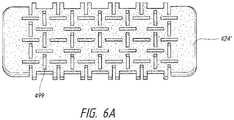
- FIGS. 6A-6Billustrates embodiments for a foam layer for use in a negative pressure wound treatment system.
- Embodiments disclosed hereinrelate to apparatuses and methods of treating a wound with reduced pressure, including a source of negative pressure and wound dressing components and apparatuses.
- the apparatuses and components comprising the wound overlay and packing materials, if any,are sometimes collectively referred to herein as dressings.
- woundrefers to a wound on a human or animal body
- bodycan refer to a human or animal body.
- woundas used herein, in addition to having its broad ordinary meaning, includes any body part of a patient that may be treated using negative pressure. It is to be understood that the term wound is to be broadly construed and encompasses open and closed wounds in which skin is torn, cut or punctured or where trauma causes a contusion, or any other superficial or other conditions or imperfections on the skin of a patient or otherwise that benefit from reduced pressure treatment.
- a woundis thus broadly defined as any damaged region of tissue where fluid may or may not be produced.
- woundsinclude, but are not limited to, abdominal wounds or other large or incisional wounds, either as a result of surgery, trauma, sterniotomies, fasciotomies, or other conditions, dehisced wounds, acute wounds, chronic wounds, subacute and dehisced wounds, traumatic wounds, flaps and skin grafts, lacerations, abrasions, contusions, burns, diabetic ulcers, pressure ulcers, stoma, surgical wounds, trauma and venous ulcers or the like.
- Treatment of such woundscan be performed using negative pressure wound therapy, wherein a reduced or negative pressure can be applied to the wound to facilitate and promote healing of the wound. It will also be appreciated that the wound dressing and methods as disclosed herein may be applied to other parts of the body, and are not necessarily limited to treatment of wounds.
- TNPtopical negative pressure
- negative pressure wound therapyassists in the closure and healing of many forms of “hard to heal” wounds by reducing tissue oedema; encouraging blood flow and granular tissue formation; removing excess exudate and may reduce bacterial load (and thus infection risk).
- the therapyallows for less disturbance of a wound leading to more rapid healing.
- TNP therapy systemsmay also assist in the healing of surgically closed wounds by removing fluid and by helping to stabilize the tissue in the apposed position of closure.
- a further beneficial use of TNP therapycan be found in grafts and flaps where removal of excess fluid is important and close proximity of the graft to tissue is required in order to ensure tissue viability.
- reduced or negative pressure levelsrepresent pressure levels relative to normal ambient atmospheric pressure, which can correspond to 760 mmHg (or 1 atm, 29.93 inHg, 101.325 kPa, 14.696 psi, etc.).
- a negative pressure value of ⁇ X mmHgreflects absolute pressure that is X mmHg below 760 mmHg or, in other words, an absolute pressure of (760 ⁇ X) mmHg.
- negative pressure that is “less” or “smaller” than X mmHgcorresponds to pressure that is closer to atmospheric pressure (e.g., ⁇ 40 mmHg is less than ⁇ 60 mmHg).
- Negative pressure that is “more” or “greater” than ⁇ X mmHgcorresponds to pressure that is further from atmospheric pressure (e.g., ⁇ 80 mmHg is more than ⁇ 60 mmHg).
- local ambient atmospheric pressureis used as a reference point, and such local atmospheric pressure may not necessarily be, for example, 760 mmHg.
- the negative pressure range for some embodiments of the present disclosurecan be approximately ⁇ 80 mmHg, or between about ⁇ 20 mmHg and ⁇ 200 mmHg Note that these pressures are relative to normal ambient atmospheric pressure, which can be 760 mmHg. Thus, ⁇ 200 mmHg would be about 560 mmHg in practical terms.
- the pressure rangecan be between about ⁇ 40 mmHg and ⁇ 150 mmHg Alternatively, a pressure range of up to ⁇ 75 mmHg, up to ⁇ 80 mmHg or over ⁇ 80 mmHg can be used. Also in other embodiments a pressure range of below ⁇ 75 mmHg can be used. Alternatively, a pressure range of over approximately ⁇ 100 mmHg, or even ⁇ 150 mmHg, can be supplied by the negative pressure apparatus.
- increased wound contractioncan lead to increased tissue expansion in the surrounding wound tissue.
- This effectmay be increased by varying the force applied to the tissue, for example by varying the negative pressure applied to the wound over time, possibly in conjunction with increased tensile forces applied to the wound via embodiments of the wound closure devices.
- negative pressuremay be varied over time for example using a sinusoidal wave, square wave, and/or in synchronization with one or more patient physiological indices (e.g., heartbeat).
- Embodiments of the wound dressings, wound treatment apparatuses and methods described hereinmay also be used in combination or in addition to those described in U.S. patent application Ser. No. 12/744,277, filed Sep. 20, 2010, patented as U.S. Pat. No. 8,764,732 on Jul. 1, 2014, titled “WOUND DRESSING,” U.S. patent application Ser. No. 12/744,218, filed Sep. 20, 2010, patented as U.S. Pat. No. 8,808,274 on Aug. 19, 2014, titled “WOUND DRESSING,” U.S. patent application Ser. No. 13/092,042, filed Apr.
- TNP wound treatmentcomprising a wound dressing in combination with a pump and/or associated electronics described herein may also be used in combination or in addition to those described in International Application No. PCT/EP2016/059329, filed Apr. 26, 2016, published as WO2016174048 A1 on Nov. 3, 2016, titled “REDUCED PRESSURE APPARATUS AND METHODS.”
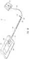
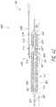
- FIGS. 1A-Billustrate embodiments of a negative pressure wound treatment system 10 employing a wound dressing 100 in conjunction with a fluidic connector 110 .
- the fluidic connector 110may comprise an elongate conduit, more preferably a bridge 120 having a proximal end 130 and a distal end 140 , and an applicator 180 at the distal end 140 of the bridge 120 .
- An optional coupling 160is preferably disposed at the proximal end 130 of the bridge 120 .
- a cap 170may be provided with the system (and can in some cases, as illustrated, be attached to the coupling 160 ). The cap 170 can be useful in preventing fluids from leaking out of the proximal end 130 .
- the system 10may include a source of negative pressure such as a pump or negative pressure unit 150 capable of supplying negative pressure.
- the pumpmay comprise a canister or other container for the storage of wound exudates and other fluids that may be removed from the wound.
- a canister or containermay also be provided separate from the pump.
- the pump 150can be a canisterless pump such as the PICOTM pump, as sold by Smith & Nephew.
- the pump 150may be connected to the coupling 160 via a tube 190 , or the pump 150 may be connected directly to the coupling 160 or directly to the bridge 120 .
- the dressing 100is placed over a suitably-prepared wound, which may in some cases be filled with a wound packing material such as foam or gauze.
- the applicator 180 of the fluidic connector 110has a sealing surface that is placed over an aperture in the dressing 100 and is sealed to the top surface of the dressing 100 .
- the pump 150is connected via the tube 190 to the coupling 160 , or is connected directly to the coupling 160 or to the bridge 120 .
- the pumpis then activated, thereby supplying negative pressure to the wound. Application of negative pressure may be applied until a desired level of healing of the wound is achieved.
- the pumpcan be miniaturized and portable, although larger conventional pumps may also be used with the dressing 100 .
- the pumpmay be attached or mounted onto or adjacent the dressing 100 .
- a source of negative pressure(such as a pump) and some or all other components of the TNP system, such as power source(s), sensor(s), connector(s), user interface component(s) (such as button(s), switch(es), speaker(s), screen(s), etc.) and the like, can be integral with the wound dressing.
- the wound dressingcan include a cover layer for positioning over the layers of the wound dressing.
- the cover layercan be the upper most layer of the dressing.
- the wound dressingcan include a second cover layer for positioning over the layers of the wound dressing and any of the integrated components.
- the second cover layercan be the upper most layer of the dressing or can be a separate envelope that encloses the integrated components of the topical negative pressure system.
- the fluidic connector 110preferably comprises an enlarged distal end, or head 140 that is in fluidic communication with the dressing 100 as will be described in further detail below.
- the enlarged distal endhas a round or circular shape.
- the head 140is illustrated here as being positioned near an edge of the dressing 100 , but may also be positioned at any location on the dressing. For example, some embodiments may provide for a centrally or off-centered location not on or near an edge or corner of the dressing 100 .
- the dressing 100may comprise two or more fluidic connectors 110 , each comprising one or more heads 140 , in fluidic communication therewith.
- the head 140may measure 30 mm along its widest edge.
- the head 140forms at least in part the applicator 180 , described above, that is configured to seal against a top surface of the wound dressing.
- FIG. 2Billustrates a cross-section through a wound dressing 100 similar to the wound dressing 100 as shown in FIG. 1B and described in International Application No. PCT/IB2013/001469, filed May 22, 2013, published as WO 2013/175306 A2 on Nov. 28, 2013, titled “APPARATUSES AND METHODS FOR NEGATIVE PRESSURE WOUND THERAPY,” the disclosure of which is hereby incorporated by reference in its entirety, along with fluidic connector 110 .
- the wound dressing 100which can alternatively be any wound dressing embodiment disclosed herein or any combination of features of any number of wound dressing embodiments disclosed herein, can be located over a wound site to be treated.
- the dressing 100may be placed as to form a sealed cavity over the wound site.
- the dressing 100comprises a top or cover layer, or backing layer 220 attached to an optional wound contact layer 222 , both of which are described in greater detail below.
- These two layers 220 , 222are preferably joined or sealed together so as to define an interior space or chamber.
- This interior space or chambermay comprise additional structures that may be adapted to distribute or transmit negative pressure, store wound exudate and other fluids removed from the wound, and other functions which will be explained in greater detail below. Examples of such structures, described below, include a transmission layer 226 and an absorbent layer 221 .
- the upper layer, top layer, or layer aboverefers to a layer furthest from the surface of the skin or wound while the dressing is in use and positioned over the wound.
- the lower surface, lower layer, bottom layer, or layer belowrefers to the layer that is closest to the surface of the skin or wound while the dressing is in use and positioned over the wound.
- the wound contact layer 222can be a polyurethane layer or polyethylene layer or other flexible layer which is perforated, for example via a hot pin process, laser ablation process, ultrasound process or in some other way or otherwise made permeable to liquid and gas.
- the wound contact layer 222has a lower surface 224 and an upper surface 223 .
- the perforations 225preferably comprise through holes in the wound contact layer 222 which enable fluid to flow through the layer 222 .
- the wound contact layer 222helps prevent tissue ingrowth into the other material of the wound dressing.
- the perforationsare small enough to meet this requirement while still allowing fluid to flow therethrough.
- perforations formed as slits or holes having a size ranging from 0.025 mm to 1.2 mmare considered small enough to help prevent tissue ingrowth into the wound dressing while allowing wound exudate to flow into the dressing.
- the wound contact layer 222may help maintain the integrity of the entire dressing 100 while also creating an air tight seal around the absorbent pad in order to maintain negative pressure at the wound.
- the wound contact layer 222may also act as a carrier for an optional lower and upper adhesive layer (not shown).
- a lower pressure sensitive adhesivemay be provided on the lower surface 224 of the wound dressing 100 whilst an upper pressure sensitive adhesive layer may be provided on the upper surface 223 of the wound contact layer.
- the pressure sensitive adhesivewhich may be a silicone, hot melt, hydrocolloid or acrylic based adhesive or other such adhesives, may be formed on both sides or optionally on a selected one or none of the sides of the wound contact layer. When a lower pressure sensitive adhesive layer is utilized may be helpful to adhere the wound dressing 100 to the skin around a wound site.
- the wound contact layermay comprise perforated polyurethane film
- the lower surface of the filmmay be provided with a silicone pressure sensitive adhesive and the upper surface may be provided with an acrylic pressure sensitive adhesive, which may help the dressing maintain its integrity.
- a polyurethane film layermay be provided with an adhesive layer on both its upper surface and lower surface, and all three layers may be perforated together.
- a layer 226 of porous materialcan be located above the wound contact layer 222 .
- This porous layer, or transmission layer, 226allows transmission of fluid including liquid and gas away from a wound site into upper layers of the wound dressing.
- the transmission layer 226preferably ensures that an open air channel can be maintained to communicate negative pressure over the wound area even when the absorbent layer has absorbed substantial amounts of exudates.
- the layer 226should preferably remain open under the typical pressures that will be applied during negative pressure wound therapy as described above, so that the whole wound site sees an equalized negative pressure.
- the layer 226may be formed of a material having a three dimensional structure. For example, a knitted or woven spacer fabric (for example Baltex 7970 weft knitted polyester) or a non-woven fabric could be used.
- the transmission layer 226comprises a 3D polyester spacer fabric layer including a top layer (that is to say, a layer distal from the wound-bed in use) which is a 84/144 textured polyester, and a bottom layer (that is to say, a layer which lies proximate to the wound bed in use) which is a 10 denier flat polyester and a third layer formed sandwiched between these two layers which is a region defined by a knitted polyester viscose, cellulose or the like mono filament fiber. Other materials and other linear mass densities of fiber could of course be used.
- top spacer fabricthus has more filaments in a yarn used to form it than the number of filaments making up the yarn used to form the bottom spacer fabric layer.
- This differential between filament counts in the spaced apart layershelps control moisture flow across the transmission layer.
- the top layeris made from a yarn having more filaments than the yarn used in the bottom layer, liquid tends to be wicked along the top layer more than the bottom layer.
- this differentialtends to draw liquid away from the wound bed and into a central region of the dressing where the absorbent layer 221 helps lock the liquid away or itself wicks the liquid onwards towards the cover layer where it can be transpired.
- the 3D fabricmay be treated with a dry cleaning agent (such as, but not limited to, Perchloro Ethylene) to help remove any manufacturing products such as mineral oils, fats and/or waxes used previously which might interfere with the hydrophilic capabilities of the transmission layer.
- a dry cleaning agentsuch as, but not limited to, Perchloro Ethylene
- an additional manufacturing stepcan subsequently be carried out in which the 3D spacer fabric is washed in a hydrophilic agent (such as, but not limited to, Feran Ice 30 g/l available from the Rudolph Group). This process step helps ensure that the surface tension on the materials is so low that liquid such as water can enter the fabric as soon as it contacts the 3D knit fabric. This also aids in controlling the flow of the liquid insult component of any exudates.
- a layer 221 of absorbent materialis provided above the transmission layer 226 .
- the absorbent materialwhich comprise a foam or non-woven natural or synthetic material, and which may optionally comprise a super-absorbent material, forms a reservoir for fluid, particularly liquid, removed from the wound site.
- the layer 10may also aid in drawing fluids towards the backing layer 220 .
- the material of the absorbent layer 221may also prevent liquid collected in the wound dressing 100 from flowing freely within the dressing, and preferably acts so as to contain any liquid collected within the dressing.
- the absorbent layer 221also helps distribute fluid throughout the layer via a wicking action so that fluid is drawn from the wound site and stored throughout the absorbent layer. This helps prevent agglomeration in areas of the absorbent layer.
- the capacity of the absorbent materialmust be sufficient to manage the exudates flow rate of a wound when negative pressure is applied. Since in use the absorbent layer experiences negative pressures the material of the absorbent layer is chosen to absorb liquid under such circumstances. A number of materials exist that are able to absorb liquid when under negative pressure, for example superabsorber material.
- the absorbent layer 221may typically be manufactured from ALLEVYNTM foam, Freudenberg 114-224-4 and/or Chem-PositeTM 11C-450.
- the absorbent layer 221may comprise a composite comprising superabsorbent powder, fibrous material such as cellulose, and bonding fibers.
- the compositeis an airlaid, thermally-bonded composite.
- the absorbent layer 221is a layer of non-woven cellulose fibers having super-absorbent material in the form of dry particles dispersed throughout.
- Use of the cellulose fibersintroduces fast wicking elements which help quickly and evenly distribute liquid taken up by the dressing.
- the juxtaposition of multiple strand-like fibersleads to strong capillary action in the fibrous pad which helps distribute liquid. In this way, the super-absorbent material is efficiently supplied with liquid.
- the wicking actionalso assists in bringing liquid into contact with the upper cover layer to aid increase transpiration rates of the dressing.
- An aperture, hole, or orifice 227is preferably provided in the backing layer 220 to allow a negative pressure to be applied to the dressing 100 .
- the fluidic connector 110is preferably attached or sealed to the top of the backing layer 220 over the orifice 227 made into the dressing 100 , and communicates negative pressure through the orifice 227 .
- a length of tubingmay be coupled at a first end to the fluidic connector 110 and at a second end to a pump unit (not shown) to allow fluids to be pumped out of the dressing.
- a length of tubingmay be coupled at a first end of the fluidic connector such that the tubing, or conduit, extends away from the fluidic connector parallel or substantially to the top surface of the dressing.
- the fluidic connector 110may be adhered and sealed to the backing layer 220 using an adhesive such as an acrylic, cyanoacrylate, epoxy, UV curable or hot melt adhesive.
- the fluidic connector 110may be formed from a soft polymer, for example a polyethylene, a polyvinyl chloride, a silicone or polyurethane having a hardness of 30 to 90 on the Shore A scale. In some embodiments, the fluidic connector 110 may be made from a soft or conformable material.
- the absorbent layer 221includes at least one through hole 228 located so as to underlie the fluidic connector 110 .
- the through hole 228may in some embodiments be the same size as the opening 227 in the backing layer, or may be bigger or smaller.
- a single through holecan be used to produce an opening underlying the fluidic connector 110 .
- multiple openingscould alternatively be utilized.
- one or multiple openingsmay be made in the absorbent layer in registration with each respective fluidic connector.
- the use of through holes in the super-absorbent layermay provide a fluid flow pathway which remains unblocked in particular when the absorbent layer is near saturation.
- the aperture or through-hole 228is preferably provided in the absorbent layer 221 beneath the orifice 227 such that the orifice is connected directly to the transmission layer 226 as illustrated in FIG. 2B .
- Thisallows the negative pressure applied to the fluidic connector 110 to be communicated to the transmission layer 226 without passing through the absorbent layer 221 .
- Thisensures that the negative pressure applied to the wound site is not inhibited by the absorbent layer as it absorbs wound exudates.
- no aperturemay be provided in the absorbent layer 221 , or alternatively a plurality of apertures underlying the orifice 227 may be provided.
- additional layerssuch as another transmission layer or an obscuring layer such as described in U.S. patent application Ser. No.
- the backing layer 220is preferably gas impermeable, but moisture vapor permeable, and can extend across the width of the wound dressing 100 .
- the backing layer 220which may for example be a polyurethane film (for example, Elastollan SP9109) having a pressure sensitive adhesive on one side, is impermeable to gas and this layer thus operates to cover the wound and to seal a wound cavity over which the wound dressing is placed. In this way, an effective chamber is made between the backing layer 220 and a wound site where a negative pressure can be established.
- the backing layer 220is preferably sealed to the wound contact layer 222 in a border region around the circumference of the dressing, ensuring that no air is drawn in through the border area, for example via adhesive or welding techniques.
- the backing layer 220protects the wound from external bacterial contamination (bacterial barrier) and allows liquid from wound exudates to be transferred through the layer and evaporated from the film outer surface.
- the backing layer 220preferably comprises two layers; a polyurethane film and an adhesive pattern spread onto the film.
- the polyurethane filmis preferably moisture vapor permeable and may be manufactured from a material that has an increased water transmission rate when wet.
- the moisture vapor permeability of the backing layerincreases when the backing layer becomes wet.
- the moisture vapor permeability of the wet backing layermay be up to about ten times more than the moisture vapor permeability of the dry backing layer.
- the absorbent layer 221may be of a greater area than the transmission layer 226 , such that the absorbent layer overlaps the edges of the transmission layer 226 , thereby ensuring that the transmission layer does not contact the backing layer 220 .
- Thisprovides an outer channel of the absorbent layer 221 that is in direct contact with the wound contact layer 222 , which aids more rapid absorption of exudates to the absorbent layer. Furthermore, this outer channel ensures that no liquid is able to pool around the circumference of the wound cavity, which could seep through the seal around the perimeter of the dressing leading to the formation of leaks.
- the absorbent layer 221may define a smaller perimeter than that of the backing layer 220 , such that a boundary or border region is defined between the edge of the absorbent layer 221 and the edge of the backing layer 220 .
- one embodiment of the wound dressing 100comprises an aperture 228 in the absorbent layer 221 situated underneath the fluidic connector 110 .
- a wound facing portion of the fluidic connectormay thus come into contact with the transmission layer 226 , which can thus aid in transmitting negative pressure to the wound site even when the absorbent layer 221 is filled with wound fluids.
- Some embodimentsmay have the backing layer 220 be at least partly adhered to the transmission layer 226 .
- the aperture 228is at least 1-2 mm larger than the diameter of the wound facing portion of the fluidic connector 110 , or the orifice 227 .
- the fluidic connector 110 and through holemay be located in an off-center position as illustrated in FIG. 2A .
- Such a locationmay permit the dressing 100 to be positioned onto a patient such that the fluidic connector 110 is raised in relation to the remainder of the dressing 100 . So positioned, the fluidic connector 110 and the filter 214 (described below) may be less likely to come into contact with wound fluids that could prematurely occlude the filter 214 so as to impair the transmission of negative pressure to the wound site.
- fluidic connector 110preferred embodiments comprise a sealing surface 216 , a bridge 211 (corresponding to bridge 120 in FIGS. 1A-1B ) with a proximal end 130 and a distal end 140 , and a filter 214 .
- the sealing surface 216preferably forms the applicator previously described that is sealed to the top surface of the wound dressing.
- a bottom layer of the fluidic connector 110may comprise the sealing surface 216 .
- the fluidic connector 110may further comprise an upper surface vertically spaced from the sealing surface 216 , which in some embodiments is defined by a separate upper layer of the fluidic connector. In other embodiments, the upper surface and the lower surface may be formed from the same piece of material.
- the sealing surface 216may comprise at least one aperture 229 therein to communicate with the wound dressing.
- the filter 214may be positioned across the opening 229 in the sealing surface, and may span the entire opening 229 .
- the sealing surface 216may be configured for sealing the fluidic connector to the cover layer of the wound dressing, and may comprise an adhesive or weld.
- the sealing surface 216may be placed over an orifice in the cover layer.
- the sealing surface 216may be positioned over an orifice in the cover layer and an aperture in the absorbent layer 220 , permitting the fluidic connector 110 to provide air flow through the transmission layer 226 .
- the bridge 211may comprise a first fluid passage 212 in communication with a source of negative pressure, the first fluid passage 212 comprising a porous material, such as a 3D knitted material, which may be the same or different than the porous layer 226 described previously.
- the bridge 211is preferably encapsulated by at least one flexible film layer 208 , 210 having a proximal and distal end and configured to surround the first fluid passage 212 , the distal end of the flexible film being connected to the sealing surface 216 .
- the filter 214is configured to substantially prevent wound exudate from entering the bridge.
- Some embodimentsmay further comprise an optional second fluid passage positioned above the first fluid passage 212 .
- some embodimentsmay provide for an air leak may be disposed at the proximal end of the top layer 208 that is configured to provide an air path into the first fluid passage 212 and dressing 100 similar to the suction adapter as described in U.S. Pat. No. 8,801,685, filed Dec. 30, 2011, entitled “APPARATUSES AND METHODS FOR NEGATIVE PRESSURE WOUND THERAPY” the disclosure of which is hereby incorporated by reference in its entirety.
- the fluid passage 212is constructed from a compliant material that is flexible and that also permits fluid to pass through it if the spacer is kinked or folded over.
- Suitable materials for the fluid passage 212include without limitation foams, including open-cell foams such as polyethylene or polyurethane foam, meshes, 3D knitted fabrics, non-woven materials, and fluid channels.
- the fluid passage 212may be constructed from materials similar to those described above in relation to the transmission layer 226 .
- such materials used in the fluid passage 212not only permit greater patient comfort, but may also provide greater kink resistance, such that the fluid passage 212 is still able to transfer fluid from the wound toward the source of negative pressure while being kinked or bent.
- the fluid passage 212may be comprised of a wicking fabric, for example a knitted or woven spacer fabric (such as a knitted polyester 3D fabric, Baltex 7970®, or Gehring 879®) or a nonwoven fabric. These materials selected are preferably suited to channeling wound exudate away from the wound and for transmitting negative pressure and/or vented air to the wound site, and may also confer a degree of kinking or occlusion resistance to the fluid passage 212 .
- the wicking fabricmay have a three-dimensional structure, which in some cases may aid in wicking fluid or transmitting negative pressure.
- the wicking fabricmay comprise several layers of material stacked or layered over each other, which may in some cases be useful in preventing the fluid passage 212 from collapsing under the application of negative pressure.
- the wicking fabric used in the fluid passage 212may be between 1.5 mm and 6 mm; more preferably, the wicking fabric may be between 3 mm and 6 mm thick, and may be comprised of either one or several individual layers of wicking fabric.
- the fluid passage 212may be between 1.2-3 mm thick, and preferably thicker than 1.5 mm.
- a suction adapter used with a dressing which retains liquid such as wound exudatemay employ hydrophobic layers in the fluid passage 212 , and only gases may travel through the fluid passage 212 .
- the materials used in the systemare preferably conformable and soft, which may help to avoid pressure ulcers and other complications which may result from a wound treatment system being pressed against the skin of a patient.
- the filter element 214is impermeable to liquids, but permeable to gases, and is provided to act as a liquid bather and to ensure that no liquids are able to escape from the wound dressing 100 .
- the filter element 214may also function as a bacterial barrier.
- the pore sizeis 0.2 ⁇ m.
- Suitable materials for the filter material of the filter element 214include 0.2 micron GoreTM expanded PTFE from the MMT range, PALL VersaporeTM 200R, and DonaldsonTM TX6628. Larger pore sizes can also be used but these may require a secondary filter layer to ensure full bioburden containment.
- the filter elementcan be attached or sealed to the port and/or the cover film over the orifice.
- the filter element 214may be molded into the fluidic connector 110 , or may be adhered to one or both of the top of the cover layer and bottom of the suction adapter 110 using an adhesive such as, but not limited to, a UV cured adhesive.
- filter element 214More generally a microporous membrane can be used which is a thin, flat sheet of polymeric material, this contains billions of microscopic pores. Depending upon the membrane chosen these pores can range in size from 0.01 to more than 10 micrometers. Microporous membranes are available in both hydrophilic (water filtering) and hydrophobic (water repellent) forms.
- filter element 214comprises a support layer and an acrylic co-polymer membrane formed on the support layer.
- the wound dressing 100according to certain embodiments of the present invention uses microporous hydrophobic membranes (MHMs). Numerous polymers may be employed to form MHMs.
- the MHMsmay be formed from one or more of PTFE, polypropylene, PVDF and acrylic copolymer. All of these optional polymers can be treated in order to obtain specific surface characteristics that can be both hydrophobic and oleophobic. As such these will repel liquids with low surface tensions such as multi-vitamin infusions, lipids, surfactants, oils and organic solvents.
- MHMsblock liquids whilst allowing air to flow through the membranes. They are also highly efficient air filters eliminating potentially infectious aerosols and particles. A single piece of MHM is well known as an option to replace mechanical valves or vents. Incorporation of MHMs can thus reduce product assembly costs improving profits and costs/benefit ratio to a patient.
- the filter element 214may also include an odor absorbent material, for example activated charcoal, carbon fiber cloth or Vitec Carbotec-RT Q2003073 foam, or the like.
- an odor absorbent materialmay form a layer of the filter element 214 or may be sandwiched between microporous hydrophobic membranes within the filter element. The filter element 214 thus enables gas to be exhausted through the orifice. Liquid, particulates and pathogens however are contained in the dressing.
- some wound dressingscomprise a perforated wound contact layer with silicone adhesive on the skin-contact face and acrylic adhesive on the reverse.
- a transmission layer or a 3D spacer fabric padAbove this bordered layer sits a transmission layer or a 3D spacer fabric pad.
- an absorbent layerAbove the transmission layer, sits an absorbent layer.
- the absorbent layercan include a superabsorbent non-woven (NW) pad.
- the absorbent layercan over-border the transmission layer by approximately 5 mm at the perimeter.
- the absorbent layercan have an aperture or through-hole toward one end. The aperture can be about 10 mm in diameter.
- a backing layerOver the transmission layer and absorbent layer lies a backing layer.
- the backing layercan be a high moisture vapor transmission rate (MVTR) film, pattern coated with acrylic adhesive.
- MVTRmoisture vapor transmission rate
- the high MVTR film and wound contact layerencapsulate the transmission layer and absorbent layer, creating a perimeter border of approximately 20 mm
- the backing layercan have a 10 mm aperture that overlies the aperture in the absorbent layer.
- Above the holecan be bonded a fluidic connector that comprises a liquid-impermeable, gas-permeable semi-permeable membrane (SPM) or filter that overlies the aforementioned apertures.
- SPMliquid-impermeable, gas-permeable semi-permeable membrane
- a source of negative pressure(such as a pump) and some or all other components of the topical negative pressure system, such as power source(s), sensor(s), connector(s), user interface component(s) (such as button(s), switch(es), speaker(s), screen(s), etc.) and the like, can be integral with the wound dressing.
- the componentscan be integrated below, within, on top of, and/or adjacent to the backing layer.
- the wound dressingcan include a second cover layer and/or a second filter layer for positioning over the layers of the wound dressing and any of the integrated components.
- the second cover layercan be the upper most layer of the dressing or can be a separate envelope that enclosed the integrated components of the topical negative pressure system.
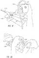
- FIGS. 3A-Dillustrate the use of an embodiment of a negative pressure therapy wound treatment system being used to treat a wound site on a patient.
- FIG. 3Ashows a wound site 1000 being cleaned and prepared for treatment.
- the healthy skin surrounding the wound site 1000is preferably cleaned and excess hair removed or shaved.
- the wound site 1000may also be irrigated with sterile saline solution if necessary.
- a skin protectantmay be applied to the skin surrounding the wound site 1000 .
- a wound packing materialsuch as foam or gauze, may be placed in the wound site 1000 . This may be preferable if the wound site 1000 is a deeper wound.
- the wound dressing 1100may be positioned and placed over the wound site 1000 .
- the wound dressing 1100is placed with the wound contact layer over and/or in contact with the wound site 1000 .
- an adhesive layeris provided on the lower surface of the wound contact layer, which may in some cases be protected by an optional release layer to be removed prior to placement of the wound dressing 1100 over the wound site 1000 .
- the dressing 1100is positioned such that the fluidic connector 1110 is in a raised position with respect to the remainder of the dressing 1100 so as to avoid fluid pooling around the port.
- the dressing 1100is positioned so that the fluidic connector 1110 is not directly overlying the wound, and is level with or at a higher point than the wound.
- the edges of the dressing 1100are preferably smoothed over to avoid creases or folds.
- the dressing 1100is connected to the pump 1150 .
- the pump 1150is configured to apply negative pressure to the wound site via the dressing 1100 , and typically through a conduit.
- a fluidic connector 1110may be used to join the conduit 1190 from the pump 1150 to the dressing 1100 .
- a length of tubingmay be coupled at a first end of the fluidic connector such that the tubing, or conduit, extends away from the fluidic connector parallel to the top of the dressing.
- the conduitmay comprise a fluidic connector.
- a conduitmay be a soft bridge, a hard tube, or any other apparatus which may serve to transport fluid.
- the dressing 1100may in some embodiments partially collapse and present a wrinkled appearance as a result of the evacuation of some or all of the air underneath the dressing 1100 .
- the pump 1150may be configured to detect if any leaks are present in the dressing 1100 , such as at the interface between the dressing 1100 and the skin surrounding the wound site 1000 . Should a leak be found, such leak is preferably remedied prior to continuing treatment.
- fixation strips 1010may also be attached around the edges of the dressing 1100 .
- Such fixation strips 1010may be advantageous in some situations so as to provide additional sealing against the skin of the patient surrounding the wound site 1000 .
- the fixation strips 1010may provide additional sealing for when a patient is more mobile.
- the fixation strips 1010may be used prior to activation of the pump 1150 , particularly if the dressing 1100 is placed over a difficult to reach or contoured area.
- Treatment of the wound site 1000preferably continues until the wound has reached a desired level of healing.
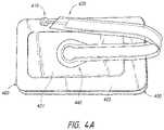
- FIG. 4Aillustrates a top view of an embodiment of a negative pressure wound treatment system employing lower wound dressing components 450 including a conforming manifold system and upper wound dressing components 460 capable of absorbing and storing wound exudate.
- the negative pressure wound dressing as illustrated in FIG. 4Aincludes a wound dressing similar to the wound dressing described with reference to FIGS. 1A-1B and 2A-2B but the wound dressing includes additional layers that form the lower wound dressing components 450 including a conforming manifold system.
- the lower wound dressing components 450can be positioned below the wound dressing components described with reference to FIGS. 1A-1B and 2A-2B .
- the upper wound dressing components 460includes upper wound dressing components 460 including a wound cover layer or top backing layer 420 and an absorbent layer 421 similar to the components described with reference to FIGS. 1A-1B and 2A-2B .
- the upper wound dressing componentscan also include an intermediate drape (not shown) below the absorbent layer. A border or perimeter portion of the intermediate drape can be sealed to the top backing layer at a perimeter of the top backing layer.
- the intermediate drapecan include an aperture to provide fluid communication with a conforming system 450 positioned between the intermediate drape and the wound as described herein.
- FIG. 4B-4Cillustrate the layers of an embodiment of a negative pressure wound treatment system of FIG. 4A employing lower wound dressing components 450 including a conforming manifold system and upper wound dressing components 460 capable of absorbing and storing wound exudate.
- the wound dressing 400can include upper wound dressing components 460 including an absorbent material and lower wound dressing components 450 including a conforming manifold.
- the lower wound dressing components 450can include a lower wound contact layer 425 , a conforming manifold or foam layer 424 , and a first backing layer 423 .
- the lower wound contact layer 425can be similar to wound contact layer 222 described with reference to FIG. 2B and can be placed in contact with the wound.
- the wound contact layer and tissue contact layercan be used interchangibly.
- the conforming manifoldcan include a foam layer 424 .
- the foam layercomprises a rectangular, rounded rectangular, racetrack, oval, circular, triangular, or irregular shape with different angles and different side sizes.
- the foam layercan have a smaller perimeter size than the tissue contact layer.
- the foam layer 424can include a reticulated foam and/or other foam, filler, transmission, or spacer layer known in the art.
- the conforming manifoldcan comprise a 30 ppi reticulated foam.
- the conforming manifoldcan comprise a 6 mm 30 ppi reticulated foam.
- the conforming manifoldcan include a foam material and/or other spacer or transmission layer.
- the terms foam, spacer, and/or transmission layercan be used interchangeably to refer to the layer of material in the dressing configured to distribute negative pressure throughout the wound area.
- the first backing layer 423can be a moisture vapor permeable film similar to the cover layer or backing layer described with reference to FIG. 2B . In other embodiments, the first backing layer 423 can be a non-permeable film In some embodiments, the first backing layer 423 can be another material that is impermeable to both liquid and gas.
- the wound contact layer 425extends across an entire area below the first backing layer 423 . In some embodiments, the wound contact layer and the first backing layer can have substantially the same perimeter size and shape.
- the foam layercan have a smaller perimeter size than the wound contact layer and the first backing layer.
- the perimeter of the first backing layer 423can be sealed to the outer perimeter of the lower wound contact layer 425 enclosing and covering the foam layer 424 .
- the first backing layer 423can include an aperture or opening 451 in the first backing layer 423 .
- the aperture or opening 451can be positioned in a center portion of the first backing layer 423 as shown in FIG. 4B .
- the lower wound dressing components 450can be used in combination with upper wound dressing components 460 including an absorbent material similar to those described with reference to FIG. 2B .
- the wound dressing systemcan include an intermediate drape 422 provided above the first backing layer.
- the intermediate drape 422can include an aperture or opening 452 .
- the aperture or opening 452can be positioned in a center portion of the intermediate drape 422 .
- the aperture 452can align with and sealed to aperture 451 of the first backing layer 423 .
- an area around the first aperturecan be sealed to an area around the second aperture to attach the first backing layer to the intermediate drape.
- the apertures 451 and 452can provide fluid communication between the two layers.
- an absorbent layer 421can be provided above the intermediate drape 422 .
- the absorbent layer 421can be similar to the absorbent material 221 described with reference to FIG. 2B .
- a second backing layer 420can be provided above the absorbent layer 421 .
- the second backing layer 420can be similar to the backing layer or cover layer 220 described with reference to FIG. 2B .
- the second backing layer 420can be the same material as the first backing layer 423 .
- the second backing layer 420can be a different material than the first backing layer 423 .
- the tissue contact layer, the first backing layer, the intermediate drape and the second backing layerall have substantially the same perimeter size and shape as shown in FIGS.
- a spacer layer or transmission layercan be provided as part of the upper would dressing components 460 .
- the spacer layercan be positioned between the intermediate drape 422 and the absorbent layer 421 similar to the layered construction described with reference to FIG. 2B .
- the absorbent material 421can be used without the spacer layer material.
- the upper wound dressing components 460can include multiple absorbent and/or multiple spacer layers.
- the second backing layer 420can include an aperture or opening 427 .
- a fluidic connector 440can be provided above the aperture or opening 427 in the second backing layer 420 .
- the fluidic connector 440can be similar to the fluidic connector 110 described with reference to FIG. 2A-2B .
- the fluidic connector 440may comprise an elongate conduit and an applicator 480 . As shown in FIG. 4C , the applicator 480 can be positioned above and sealed to or around the aperture or opening 427 in the second backing layer 420 for delivering negative pressure to the wound dressing 400 .
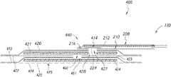
- FIG. 4Cillustrates a cross-section of an embodiment of a negative pressure wound treatment system employing lower wound dressing components including a foam layer capable of conforming to a patient and upper wound dressing components capable of absorbing and storing wound exudate.
- reference numerals and like-named components in FIG. 4Crefer to components that are the same as or generally similar to the components of FIG. 2B .
- a port 440can be provided over an opening 427 in the second backing layer 420 .
- the portcan include a filter 414 .
- a negative pressure sourcecan be in fluid communication with the port 440 and/or opening 427 in the second backing layer. The negative pressure source can apply negative pressure through the opening or aperture 427 in the second backing layer.
- the apertures 427 , 452 , 451 in the second backing layer 420 , intermediate layer 422 , and first backing layer 423can provide fluid communication between the negative pressure source and the wound.
- the absorbent layer 421can include a through-hole 428 extending through the absorbent layer 421 .
- the through-hole 428can be aligned underneath the filter 414 as illustrated in FIG. 4C .
- the through-hole 428can be offset from the filter 414 .
- the components of the wound dressingcan be kept aligned by using a central dab of glue.
- aperture 451 and aperture 452can be positioned at a central portion of the intermediate drape 422 and first backing layer 423 , respectively, as shown in FIGS. 4A-4C . In some embodiments, aperture 451 and aperture 452 can be positioned in a corner, at an edge, or in any portion of the intermediate drape 422 and first backing layer 423 , respectively. In some embodiments, the apertures or openings 451 , 452 can be a rectangular opening or slit forming a channel when aligned and sealed to the aperture or opening 452 . In some embodiments, the intermediate drape 422 and first backing layer 423 can have two or more apertures or openings to provide fluid communication between the conforming manifold system 450 and the absorbent material of the wound dressing.
- the apertures 451 and 452can be positioned offset from the filter 414 and through-hole 428 as illustrated in FIG. 4C . In other embodiments, the apertures 451 and 452 can be aligned underneath the filter 414 and through-hole 428 .
- the wound dressing systemincludes the lower wound dressing components with the conforming manifold for conforming to a patient in communication with absorbent materials of the upper wound dressing components for absorbing and storing wound exudate.
- the absorbent dressing components as described abovecan be stiffer or more rigid than foam or transmission layers that may be utilized as components of the dressing. Therefore, in some embodiments, the stiffer) components of the dressing can be decoupled from a foam or a lower spacer layer as described herein.
- the structure described hereincan allow the dressing to have the ability to conform to a contoured region of the body of a patient while also allowing for the stiffer absorbent dressing components to be incorporated into the upper wound dressing components 460 of the wound dressing.
- the upper wound dressing componentswhen using a conforming manifold system, can fold like an anemone when negative pressure is applied as described further herein.
- the foamcan have compressibility to generate good moulding and absence of imprinting.
- the lower wound dressing componentscan provide a more complete and effective seal to the patient's body.
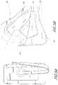
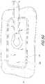
- FIGS. 5A-5Gillustrates an embodiment of a negative pressure wound treatment system employing lower wound dressing components including a foam layer capable of conforming to a patient and upper wound dressing components capable of absorbing and storing wound exudate.
- FIG. 5Aillustrates a top view of the wound dressing described herein.
- FIG. 5Billustrates an embodiment of the wound dressing with the upper wound dressing components 460 lifted away from the lower wound dressing components 450 .
- the lower wound dressing componentsinclude the foam or lower spacer layer 424 enclosed within the first backing layer 423 and the lower wound contact layer (not shown).
- the absorbent material 421is illustrated enclosed within the intermediate drape 422 and the second backing layer 420 forming the upper wound dressing components 460 above the lower wound dressing components 450 .
- FIG. 5Cillustrate an embodiment of the wound dressing with lower wound dressing components positioned on a contoured portion of a patient's body.
- the lower wound dressing components 450are placed on the contoured body portion of a patient and sealed to the skin.
- the lower wound dressing components 450will wrap around and conform to the body while the upper wound dressing components 460 bend and conform less to the area of the body.
- the first backing layer 423 and/or the wound contact layer 425can be flexible enough to not restrict movement or bending of the lower spacer layer 424 as it conforms to the contoured shape.
- the first backing layer 423 and/or the wound contact layer 425can have additional material so as not to restrict movement of bending of the lower spacer layer 424 as it conforms to the contoured shape.
- FIG. 5D-5Fillustrate embodiments of the wound dressing after negative pressure has been applied.
- the lower wound dressing components 450are sucked down and conformed to the body portion and the upper wound dressing components 460 are folded and creased.
- the upper wound dressing components 460can be folded and sucked down in a manner similar to the shape and movement of an anemone.
- the upper wound dressing componentscan be sucked inward and down toward the connection point in the apertures in the intermediate drape and first backing layer.
- the upper wound dressing components 460can fold inward from a center portion and can fold in on itself as the edges are pushed in and up as shown in FIGS. 5D-5F .
- the second backing layer 420 and/or the intermediate drape 422can be flexible enough to not restrict movement or bending of the absorbent components as it is sucked in, folded, and/or creased. In some embodiments, the second backing layer 420 and/or the intermediate drape 422 can have additional material so as not to restrict movement of bending of the absorbent components while being sucked in, folded, and/or creased.
- FIG. 5Gillustrates an embodiment of a negative pressure wound treatment system employing lower wound dressing components including a foam layer capable of conforming to a patient and upper wound dressing components capable of absorbing and storing wound exudate.
- the foam or spacer layer 424 of the lower wound dressing componentscan have a larger diameter and extend outward beyond the perimeter of the absorbent material 421 .
- the foam or lower space layer 424can have a perimeter size that is bigger than the absorbent layer 421 and/or the spacer layer of the absorbent dressing components on top of it. In some embodiments, this can guard against pad edge imprinting.
- the lower spacer layer 424can be about 5 mm bigger all around than the absorbent layer 421 .
- the lower spacer layer or foam layer 424 ′can include slits or cut outs 499 in the foam material as illustrated in FIG. 6A-6B .
- the slit or cut out modification to the foam or spacer material 424 ′can provide a further increase in the materials ability to conform to a contoured shape or body portion.
- FIGS. 6A-6Billustrates embodiments of foam layer 424 ′ for use in a negative pressure wound treatment system. When utilizing the foam slits or cut outs 499 , the foam material can be stiffer and the slits will still allow the contouring of the foam or spacer layer material 424 ′ to the body of the patient.
- the slits or cut outs 499can include one or more slits or cut outs that are horizontal (extend parallel to a length of the foam or spacer material 424 ′).
- the slits or cut outs 499can include one or more slits or cut outs that are vertical (extend perpendicular to a length of the foam or spacer material 424 ′).
- the slits or cut outs 499can include one or more slits or cut outs that are horizontal and one or more slits or cut outs that are vertical as shown in FIGS. 6A-6B .
- the foam or spacer material 424 ′can conform and wrap around a contoured body region of a patient along both the length and width of the foam or spacer material 424 ′.
- the slits or cut outs 499can be distributed throughout the foam or spacer material 424 ′.
- the slits or cut outscan be localized to a portion of the foam or spacer material 424 ′.
- the slits or cut outscan be only in a center portion and/or only on an edge portion.
- the slits or cut outs 499can be provided in a pattern and/or evenly distributed on the foam or spacer material 424 ′. In some embodiments, the slits or cut outs 499 can be randomly distributed or provided on the foam or spacer layer 424 ′.
Landscapes
- Health & Medical Sciences (AREA)
- Heart & Thoracic Surgery (AREA)
- Public Health (AREA)
- Vascular Medicine (AREA)
- Engineering & Computer Science (AREA)
- Biomedical Technology (AREA)
- Veterinary Medicine (AREA)
- Life Sciences & Earth Sciences (AREA)
- Animal Behavior & Ethology (AREA)
- General Health & Medical Sciences (AREA)
- Anesthesiology (AREA)
- Hematology (AREA)
- Dermatology (AREA)
- Media Introduction/Drainage Providing Device (AREA)
- Materials For Medical Uses (AREA)
- Massaging Devices (AREA)
Abstract
Description
Claims (25)
Priority Applications (1)
| Application Number | Priority Date | Filing Date | Title |
|---|---|---|---|
| US16/622,207US11471333B2 (en) | 2017-06-14 | 2018-06-11 | Negative pressure wound therapy apparatus |
Applications Claiming Priority (3)
| Application Number | Priority Date | Filing Date | Title |
|---|---|---|---|
| US201762519762P | 2017-06-14 | 2017-06-14 | |
| US16/622,207US11471333B2 (en) | 2017-06-14 | 2018-06-11 | Negative pressure wound therapy apparatus |
| PCT/EP2018/065396WO2018229008A1 (en) | 2017-06-14 | 2018-06-11 | Negative pressure wound therapy apparatus |
Related Parent Applications (1)
| Application Number | Title | Priority Date | Filing Date |
|---|---|---|---|
| PCT/EP2018/065396A-371-Of-InternationalWO2018229008A1 (en) | 2017-06-14 | 2018-06-11 | Negative pressure wound therapy apparatus |
Related Child Applications (1)
| Application Number | Title | Priority Date | Filing Date |
|---|---|---|---|
| US17/895,482ContinuationUS20230065604A1 (en) | 2017-06-14 | 2022-08-25 | Negative pressure wound therapy apparatus |
Publications (2)
| Publication Number | Publication Date |
|---|---|
| US20200107965A1 US20200107965A1 (en) | 2020-04-09 |
| US11471333B2true US11471333B2 (en) | 2022-10-18 |
Family
ID=62599604
Family Applications (2)
| Application Number | Title | Priority Date | Filing Date |
|---|---|---|---|
| US16/622,207Active2038-10-25US11471333B2 (en) | 2017-06-14 | 2018-06-11 | Negative pressure wound therapy apparatus |
| US17/895,482PendingUS20230065604A1 (en) | 2017-06-14 | 2022-08-25 | Negative pressure wound therapy apparatus |
Family Applications After (1)
| Application Number | Title | Priority Date | Filing Date |
|---|---|---|---|
| US17/895,482PendingUS20230065604A1 (en) | 2017-06-14 | 2022-08-25 | Negative pressure wound therapy apparatus |
Country Status (7)
| Country | Link |
|---|---|
| US (2) | US11471333B2 (en) |
| EP (1) | EP3638167B1 (en) |
| JP (1) | JP7155162B2 (en) |
| CN (1) | CN110662517B (en) |
| AU (1) | AU2018285235B2 (en) |
| CA (1) | CA3065380A1 (en) |
| WO (1) | WO2018229008A1 (en) |
Cited By (2)
| Publication number | Priority date | Publication date | Assignee | Title |
|---|---|---|---|---|
| US20230065604A1 (en)* | 2017-06-14 | 2023-03-02 | T.J.Smith And Nephew,Limited | Negative pressure wound therapy apparatus |
| US11878104B2 (en) | 2020-02-20 | 2024-01-23 | Convatec Limited | Wound dressing and a wound therapy apparatus |
Families Citing this family (39)
| Publication number | Priority date | Publication date | Assignee | Title |
|---|---|---|---|---|
| GB0808376D0 (en) | 2008-05-08 | 2008-06-18 | Bristol Myers Squibb Co | Wound dressing |
| GB0817796D0 (en) | 2008-09-29 | 2008-11-05 | Convatec Inc | wound dressing |
| GB201020236D0 (en) | 2010-11-30 | 2011-01-12 | Convatec Technologies Inc | A composition for detecting biofilms on viable tissues |
| WO2012078724A1 (en) | 2010-12-08 | 2012-06-14 | Convatec Technologies Inc. | Apparatus and method for applying pressure to a wound site |
| US10207031B2 (en) | 2010-12-08 | 2019-02-19 | Convatec Technologies Inc. | Integrated system for assessing wound exudates |
| ES2748519T3 (en) | 2010-12-08 | 2020-03-17 | Convatec Technologies Inc | Wound exudate system accessory |
| GB201115182D0 (en) | 2011-09-02 | 2011-10-19 | Trio Healthcare Ltd | Skin contact material |
| GB2497406A (en) | 2011-11-29 | 2013-06-12 | Webtec Converting Llc | Dressing with a perforated binder layer |
| JP2016507663A (en) | 2012-12-20 | 2016-03-10 | コンバテック・テクノロジーズ・インコーポレイテッドConvatec Technologies Inc | Processing of chemically modified cellulosic fibers |
| WO2015172108A1 (en) | 2014-05-09 | 2015-11-12 | Kci Licensing, Inc. | Dressing with contracting layer for linear tissue sites |
| WO2015172111A1 (en) | 2014-05-09 | 2015-11-12 | Kci Licensing, Inc. | Disruptive dressing for use with negative pressure and fluid instillation |
| US10898217B2 (en) | 2014-05-09 | 2021-01-26 | Kci Licensing, Inc. | Dressing providing apertures with multiple orifice sizes for negative-pressure therapy |
| GB2543544A (en) | 2015-10-21 | 2017-04-26 | Brightwake Ltd | Wound dressing |
| AU2017243601A1 (en) | 2016-03-30 | 2018-11-22 | Acib Gmbh | Detecting microbial infection in wounds |
| PL3435941T3 (en) | 2016-03-30 | 2022-05-09 | Convatec Technologies Inc. | Detecting microbial infections in wounds |
| EP3481348A4 (en) | 2016-07-08 | 2020-02-26 | ConvaTec Technologies Inc. | Fluid collection apparatus |
| MX2019000232A (en) | 2016-07-08 | 2019-11-12 | Convatec Technologies Inc | Fluid flow sensing. |
| DK3481349T3 (en) | 2016-07-08 | 2021-07-12 | Convatec Technologies Inc | Flexible vacuum system |
| USD874642S1 (en)* | 2017-09-29 | 2020-02-04 | Mölnlycke Health Care Ab | Medical equipment |
| USD983351S1 (en) | 2017-04-03 | 2023-04-11 | Mölnlycke Health Care Ab | Medical equipment |
| CN111836655A (en) | 2017-11-16 | 2020-10-27 | 康沃特克有限公司 | fluid collection equipment |
| CN113507908A (en)* | 2018-11-08 | 2021-10-15 | 3M创新知识产权公司 | Wound dressing with semi-rigid support for increased disruption using perforated dressing and negative pressure wound therapy |
| USD895787S1 (en)* | 2019-05-10 | 2020-09-08 | Kci Licensing, Inc. | Negative pressure therapy device |
| EP3969071A1 (en)* | 2019-05-13 | 2022-03-23 | KCI Licensing, Inc. | Dressing including outlet connection fluid buffer |
| EP4295869A3 (en) | 2019-06-03 | 2024-03-20 | Convatec Limited | Methods and devices to disrupt and contain pathogens |
| GB201914706D0 (en) | 2019-10-11 | 2019-11-27 | Smith & Nephew | Apparatuses and methods for negative pressure wound therapy with switcheable fluid management |
| GB201914725D0 (en)* | 2019-10-11 | 2019-11-27 | Smith & Nephew | Apparatuses and methods for negative pressure wound therapy |
| US12274636B2 (en)* | 2019-11-01 | 2025-04-15 | Kci Manufacturing Unlimited Company | Decompression therapy treatment system |
| EP4051201B1 (en)* | 2019-11-01 | 2024-05-29 | KCI Manufacturing Unlimited Company | Decompression therapy treatment system |
| US12409072B2 (en) | 2019-12-05 | 2025-09-09 | Kci Manufacturing Unlimited Company | Multi-layer negative pressure incisional wound therapy dressing |
| US11771819B2 (en) | 2019-12-27 | 2023-10-03 | Convatec Limited | Low profile filter devices suitable for use in negative pressure wound therapy systems |
| US11331221B2 (en) | 2019-12-27 | 2022-05-17 | Convatec Limited | Negative pressure wound dressing |
| GB202004812D0 (en)* | 2020-04-01 | 2020-05-13 | Smith & Nephew | Apparatuses and methods for negative pressure wound therapy |
| GB202006305D0 (en)* | 2020-04-29 | 2020-06-10 | Smith & Nephew | Apparatures and methods for negative pressure wound therapy |
| ES2984023T3 (en)* | 2020-05-25 | 2024-10-28 | Moelnlycke Health Care Ab | A dressing for negative pressure wound therapy (NPWT) |
| EP4228575B1 (en)* | 2020-12-01 | 2025-09-03 | KCI Manufacturing Unlimited Company | Contractible dressing manifold with reduced tissue in-growth |
| US20220280701A1 (en)* | 2021-03-03 | 2022-09-08 | April Corella | Self-Enclosed Negative Pressure Wound Therapy Device |
| CN113712735A (en)* | 2021-11-03 | 2021-11-30 | 上海大博医疗科技有限公司 | Portable wound surface management dressing |
| CN115462963B (en)* | 2022-10-17 | 2024-06-18 | 刘建华 | Wound surface application and preparation method thereof |
Citations (159)
| Publication number | Priority date | Publication date | Assignee | Title |
|---|---|---|---|---|
| FR1163907A (en) | 1956-10-25 | 1958-10-02 | Skin care devices | |
| GB1255395A (en) | 1968-03-09 | 1971-12-01 | Merck Patent Gmbh | Non-bleeding indicator papers, foils, powders and formed bodies |
| US3972328A (en) | 1975-07-28 | 1976-08-03 | E. R. Squibb & Sons, Inc. | Surgical bandage |
| US4029598A (en) | 1969-03-14 | 1977-06-14 | E. Merck A. G. | Non-bleeding indicator and dyes therefor |
| WO1983000742A1 (en) | 1981-08-26 | 1983-03-03 | Towsend, Marvin, S. | Disposable article with non-leachable saline water indicator |
| US4499896A (en)* | 1982-03-30 | 1985-02-19 | Minnesota Mining And Manufacturing Co. | Reservoir wound dressing |
| DE3443101A1 (en) | 1984-11-27 | 1986-05-28 | Artur 6230 Frankfurt Beudt | Covering device for open wounds |
| US4728499A (en) | 1986-08-13 | 1988-03-01 | Fehder Carl G | Carbon dioxide indicator device |
| US4813942A (en) | 1987-03-17 | 1989-03-21 | Bioderm, Inc. | Three step wound treatment method and dressing therefor |
| EP0340018A2 (en) | 1988-04-28 | 1989-11-02 | Minnesota Mining And Manufacturing Company | Composition, apparatus and method for sensing ionic components |
| US5056510A (en) | 1989-04-13 | 1991-10-15 | The Kendall Company | Vented wound dressing |
| US5181905A (en) | 1989-11-28 | 1993-01-26 | Eric Flam | Method of monitoring the condition of the skin or wound |
| US5238732A (en) | 1992-07-16 | 1993-08-24 | Surface Coatings, Inc. | Waterproof breathable polyurethane membranes and porous substrates protected therewith |
| WO1996005873A1 (en) | 1994-08-22 | 1996-02-29 | Kinetic Concepts Inc. | Wound drainage equipment |
| US5549584A (en) | 1994-02-14 | 1996-08-27 | The Kendall Company | Apparatus for removing fluid from a wound |
| US5707499A (en) | 1995-10-06 | 1998-01-13 | Ceramatec, Inc. | Storage-stable, fluid dispensing device using a hydrogen gas generator |
| US5730736A (en) | 1996-04-30 | 1998-03-24 | Dansac A/S | Ostomy appliance and contoured adhesive wafer therefor |
| US5759570A (en) | 1992-11-23 | 1998-06-02 | Johnson & Johnson Medical, Inc. | Multi-layer wound dressing |
| US5852126A (en) | 1994-05-02 | 1998-12-22 | Novartis Ag | Polymerisable composition and the use thereof |
| US6071267A (en) | 1998-02-06 | 2000-06-06 | Kinetic Concepts, Inc. | Medical patient fluid management interface system and method |
| WO2001085248A1 (en) | 2000-05-09 | 2001-11-15 | Kci Licensing, Inc. | Abdominal wound dressing |
| US20030125646A1 (en) | 2001-12-29 | 2003-07-03 | Whitlock Russell Ward | Device and method for relieving pain |
| US6626891B2 (en) | 1997-07-03 | 2003-09-30 | Polymedics N.V. | Drainage system to be used with an open wound, an element which is used thereby for placing a drainage tube or hose, and a method of using said drainage system |
| US6685681B2 (en) | 2000-11-29 | 2004-02-03 | Hill-Rom Services, Inc. | Vacuum therapy and cleansing dressing for wounds |
| US20040057855A1 (en) | 2002-06-20 | 2004-03-25 | B. Braun Melsungen Ag | Syringe pump |
| WO2004077387A1 (en) | 2003-02-27 | 2004-09-10 | Bang & Olufsen A/S | Metal structure with translucent region |
| WO2005025447A2 (en) | 2003-09-08 | 2005-03-24 | Microlin, L.C. | Device ανd method for wound therapy |
| US6936037B2 (en) | 2002-12-31 | 2005-08-30 | Kci Licensing, Inc. | Tissue closure treatment system, patient interface and method |
| US6979324B2 (en) | 2002-09-13 | 2005-12-27 | Neogen Technologies, Inc. | Closed wound drainage system |
| US20060009744A1 (en) | 2004-07-09 | 2006-01-12 | Erdman Edward P | Decorative component for an absorbent article |
| US7070584B2 (en) | 2001-02-20 | 2006-07-04 | Kci Licensing, Inc. | Biocompatible wound dressing |
| US7108683B2 (en) | 2001-04-30 | 2006-09-19 | Kci Licensing, Inc | Wound therapy and tissue management system and method with fluid differentiation |
| US20070040454A1 (en) | 2005-08-22 | 2007-02-22 | Prominent Dosiertechnik Gmbh | Magnetic drive metering pump |
| US7216651B2 (en) | 1991-11-14 | 2007-05-15 | Wake Forest University Health Sciences | Wound treatment employing reduced pressure |
| US20070225663A1 (en) | 2004-06-21 | 2007-09-27 | Watt Paul W | Wound dressings for vacuum therapy |
| US20080031748A1 (en) | 2006-04-28 | 2008-02-07 | Olai Ihle | Centrifugal pump |
| EP1476217B1 (en) | 2001-12-26 | 2008-03-05 | Hill-Rom Services, Inc. | Vacuum bandage packing |
| WO2008039223A1 (en) | 2006-09-26 | 2008-04-03 | Boehringer Technologies L.P. | Pump system for negative pressure wound therapy |
| US20080132821A1 (en) | 2005-08-23 | 2008-06-05 | Tri-State Hospital Supply Corporation | Window dressing |
| EP1955887A2 (en) | 2007-02-08 | 2008-08-13 | Automotive Components Holdings, LLC | Attaching a component to an internal surface of a tank formed of polymer |
| US20090125004A1 (en) | 2007-11-09 | 2009-05-14 | Industrial Technology Research Institute | Detachable pump and the negative pressure wound therapy system using the same |
| US20090157024A1 (en) | 2007-12-14 | 2009-06-18 | Kimberly-Clark Worldwide, Inc. | Hydration Test Devices |
| US20090234306A1 (en) | 2008-03-13 | 2009-09-17 | Tyco Healthcare Group Lp | Vacuum wound therapy wound dressing with variable performance zones |
| WO2009124100A1 (en) | 2008-04-04 | 2009-10-08 | 3M Innovative Properties Company | Wound dressing with micropump |
| US7605298B2 (en) | 2004-01-09 | 2009-10-20 | Bio-Gate Ag | Wound covering |
| US7615036B2 (en) | 2006-05-11 | 2009-11-10 | Kalypto Medical, Inc. | Device and method for wound therapy |
| US7622629B2 (en) | 2005-12-15 | 2009-11-24 | Aalnex, Inc. | Wound shield for exudate management |
| US7625362B2 (en) | 2003-09-16 | 2009-12-01 | Boehringer Technologies, L.P. | Apparatus and method for suction-assisted wound healing |
| US20090299306A1 (en) | 2008-05-27 | 2009-12-03 | John Buan | Control unit with pump module for a negative pressure wound therapy device |
| US7700819B2 (en) | 2001-02-16 | 2010-04-20 | Kci Licensing, Inc. | Biocompatible wound dressing |
| US7718249B2 (en) | 2003-07-11 | 2010-05-18 | Nonwovens Innovation & Research Institute Limited | Nonwoven spacer fabric |
| US20100125258A1 (en) | 2008-11-14 | 2010-05-20 | Richard Daniel John Coulthard | Fluid pouch, system, and method for storing fluid from a tissue site |
| US7722582B2 (en) | 1999-04-09 | 2010-05-25 | Kci Licensing, Inc. | Wound therapy device |
| US7749531B2 (en) | 2005-06-08 | 2010-07-06 | Indicator Systems International | Apparatus and method for detecting bacterial growth beneath a wound dressing |
| US7759537B2 (en) | 2004-02-13 | 2010-07-20 | Convatec Technologies Inc. | Multi layered wound dressing |
| US7759539B2 (en) | 2003-01-10 | 2010-07-20 | Convatec Technologies Inc. | Wound dressing |
| US20100185163A1 (en)* | 2009-01-20 | 2010-07-22 | Tyco Healthcare Group Lp | Method and Apparatus for Bridging From a Dressing in Negative Pressure Wound Therapy |
| US7775998B2 (en) | 2004-11-02 | 2010-08-17 | Birgit Riesinger | Multi-component dressing for treating wounds of the human or animal body using a reduced pressure |
| US7811269B2 (en) | 2001-08-24 | 2010-10-12 | Kci Licensing, Inc. | Negative pressure assisted tissue treatment system |
| US20100259406A1 (en) | 2009-04-10 | 2010-10-14 | Tenacore Holdings, Inc. | System and method for measuring fluid pressure |
| US20100318052A1 (en) | 2009-06-16 | 2010-12-16 | 3M Innovative Properties Company | Conformable medical dressing with self supporting substrate |
| WO2010142959A2 (en) | 2009-06-10 | 2010-12-16 | Systagenix Wound Management Ip Co. B.V. | Hydrogel wound dressing for use with suction |
| US20110004172A1 (en) | 2009-07-06 | 2011-01-06 | Paul Hartmann Ag | Device for vacuum therapy of wounds |
| US7910791B2 (en) | 2000-05-22 | 2011-03-22 | Coffey Arthur C | Combination SIS and vacuum bandage and method |
| US7922703B2 (en) | 2004-11-24 | 2011-04-12 | Birgit Riesinger | Drainage device for treating wounds using a reduced pressure |
| US7976519B2 (en) | 2002-12-31 | 2011-07-12 | Kci Licensing, Inc. | Externally-applied patient interface system and method |
| US20110224631A1 (en) | 2010-03-11 | 2011-09-15 | Tyler Simmons | Dressings, systems, and methods for treating a tissue site |
| WO2011135285A1 (en) | 2010-04-27 | 2011-11-03 | Smith & Nephew Plc | Wound dressing |
| WO2011135286A1 (en) | 2010-04-27 | 2011-11-03 | Smith & Nephew Plc | Wound dressing |
| WO2011135287A1 (en) | 2010-04-27 | 2011-11-03 | Smith & Nephew Plc | Suction port |
| US8062331B2 (en) | 2002-08-21 | 2011-11-22 | Kci Licensing, Inc. | Internal and external medical closure screen systems and methods |
| WO2011144888A1 (en) | 2010-05-19 | 2011-11-24 | Smith & Nephew Plc | Wound protection |
| US20120051945A1 (en) | 2010-07-19 | 2012-03-01 | Sentrinsic, Inc. | Speed control for diaphragm pump |
| US8152785B2 (en) | 2008-03-13 | 2012-04-10 | Tyco Healthcare Group Lp | Vacuum port for vacuum wound therapy |
| US20120109083A1 (en)* | 2010-10-27 | 2012-05-03 | Kci Licensing, Inc. | Reduced-pressure systems, dressings, and methods employing a wireless pump |
| EP2462908A1 (en) | 2010-12-10 | 2012-06-13 | Industrial Technology Research Institute | Medical dressing and negative pressure wound therapy apparatus using the same |
| US8235972B2 (en) | 2006-02-01 | 2012-08-07 | Carmeli Adahan | Suctioning system, method and kit |
| US8241261B2 (en) | 2008-05-30 | 2012-08-14 | Kci Licensing, Inc. | Super-absorbent, reduced-pressure wound dressings and systems |
| WO2012131237A1 (en) | 2011-03-25 | 2012-10-04 | Laboratoires Urgo | Film-forming composition containing a sun filter, and use thereof for the treatment of scars |
| WO2012143665A1 (en) | 2011-04-21 | 2012-10-26 | Smith & Nephew Plc | Blockage management |
| US8303552B2 (en) | 2004-04-05 | 2012-11-06 | Bluesky Medical Group, Inc. | Reduced pressure wound treatment system |
| WO2013010907A1 (en) | 2011-07-18 | 2013-01-24 | Laboratoires Urgo | Negative pressure wound treatment assembly |
| US8372050B2 (en) | 2008-03-05 | 2013-02-12 | Kci Licensing, Inc. | Dressing and method for applying reduced pressure to and collecting and storing fluid from a tissue site |
| US20130066285A1 (en) | 2011-09-14 | 2013-03-14 | Christopher Brian Locke | Reduced-pressure systems and methods employing a leak-detection member |
| US20130066289A1 (en) | 2011-09-12 | 2013-03-14 | Xuedong Song | Wetness Indicator Having Varied Hues |
| US20130090616A1 (en) | 2010-06-16 | 2013-04-11 | Norbert Neubauer | Device for wound treatment and a wound covering bandage or dressing |
| US8425478B2 (en) | 2008-09-18 | 2013-04-23 | Kci Licensing, Inc. | Multi-layer dressings, systems, and methods for applying reduced pressure at a tissue site |
| WO2013064852A1 (en) | 2011-11-02 | 2013-05-10 | Smith & Nephew Plc | Reduced pressure therapy apparatuses and methods of using same |
| US20130131616A1 (en) | 2011-11-23 | 2013-05-23 | Kci Licensing, Inc. | Reduced pressure tissue treatment systems and methods having a reduced pressure dressing and associated valve |
| US20130138054A1 (en) | 2005-02-15 | 2013-05-30 | Wilhelm Fleischmann | Wound treatment device |
| US20130144227A1 (en) | 2011-11-23 | 2013-06-06 | Christopher Brian Locke | Reduced-pressure systems, methods, and devices for simultaneously treating a plurality of tissue sites |
| WO2013083800A1 (en) | 2011-12-09 | 2013-06-13 | Birgit Riesinger | Set comprising wound dressing and wound filler |
| WO2013090810A1 (en) | 2011-12-16 | 2013-06-20 | Kci Licensing, Inc. | Releasable medical drapes |
| US20130165878A1 (en) | 2009-01-26 | 2013-06-27 | Tyco Healthcare Group Lp | Wound Filler Material with Improved Nonadherency Properties |
| US8513481B2 (en) | 2009-06-15 | 2013-08-20 | Molnlycke Health Care Ab | Wound dressing with high liquid handling capacity |
| US8540688B2 (en) | 2011-05-13 | 2013-09-24 | Paul Hartmann Ag | Vacuum generation device for vacuum treatment of wounds |
| US8545466B2 (en) | 2007-06-27 | 2013-10-01 | Mölnlycke Health Care Ab | Device for treatment of wounds with reduced pressure |
| WO2013149078A1 (en) | 2012-03-28 | 2013-10-03 | Kci Licensing, Inc. | Reduced-pressure systems, dressings, and methods facilitating separation of electronic and clinical component parts |
| US8568386B2 (en) | 2009-05-11 | 2013-10-29 | Smith & Nephew, Inc. | Orientation independent canister for a negative pressure wound therapy device |
| US20130296762A1 (en) | 2010-12-08 | 2013-11-07 | Convatec Technologies Inc. | Self-sealing dressing |
| US20130302545A1 (en) | 2011-02-02 | 2013-11-14 | Pierburg Gmbh | Workpiece part and method for connecting workpiece parts by laser beams |
| WO2014008348A2 (en) | 2012-07-05 | 2014-01-09 | Kci Licensing, Inc. | Systems and methods for supplying reduced pressure using a disc pump with electrostatic actuation |
| US8628505B2 (en) | 2002-09-03 | 2014-01-14 | Bluesky Medical Group Incorporated | Reduced pressure treatment system |
| WO2014016759A1 (en) | 2012-07-23 | 2014-01-30 | Commissariat A L'energie Atomique Et Aux Energies Alternatives | Item intended to come into contact with a liquid, in particular a bandage |
| US8641691B2 (en) | 2006-09-28 | 2014-02-04 | Smith & Nephew, Inc. | Portable wound therapy system |
| WO2014020440A1 (en)* | 2012-08-01 | 2014-02-06 | Smith & Nephew Plc | Wound dressing |
| US8663198B2 (en) | 2009-04-17 | 2014-03-04 | Kalypto Medical, Inc. | Negative pressure wound therapy device |
| US20140114268A1 (en) | 2011-04-15 | 2014-04-24 | Laboratoires Urgo | Very absorbent, thin adhesive dressing, and uses thereof for the treatment of chronic wounds |
| US20140200533A1 (en) | 2013-01-16 | 2014-07-17 | Kci Licensing, Inc. | Dressing with asymmetric absorbent core for negative pressure wound therapy |
| WO2014108476A1 (en) | 2013-01-09 | 2014-07-17 | Birgit Riesinger | Liquid-permeable primary dressing with a silicone coating |
| US8795243B2 (en) | 2004-05-21 | 2014-08-05 | Bluesky Medical Group Incorporated | Flexible reduced pressure treatment appliance |
| US8795800B2 (en) | 2010-03-31 | 2014-08-05 | Bsn Medical, Inc. | Water resistant medical bandaging product |
| WO2014140606A1 (en)* | 2013-03-15 | 2014-09-18 | Smith & Nephew Plc | Wound dressing and method of treatment |
| US20140316359A1 (en)* | 2013-03-15 | 2014-10-23 | Smith & Nephew Plc | Wound dressing and method of treatment |
| US20150032035A1 (en) | 2012-02-01 | 2015-01-29 | Paul Banwell | Scar reduction apparatus |
| WO2015022334A1 (en) | 2013-08-12 | 2015-02-19 | Birgit Riesinger | Wound care article having a substantially polygonal or ellipsoid main surface and at least one recess arranged on one side |
| WO2015022340A1 (en) | 2013-08-12 | 2015-02-19 | Birgit Riesinger | Wound care article having super-absorbent fibers and super-absorbent particles |
| US20150119831A1 (en) | 2013-10-30 | 2015-04-30 | Kci Licensing, Inc. | Condensate absorbing and dissipating system |
| US20150119832A1 (en) | 2013-10-30 | 2015-04-30 | Kci Licensing, Inc. | Dressing with sealing and retention interface |
| US20150119833A1 (en) | 2013-10-30 | 2015-04-30 | Kci Licensing, Inc. | Dressing with differentially sized perforations |
| US20150141941A1 (en)* | 2012-05-23 | 2015-05-21 | Smith & Nephew Plc | Apparatuses and methods for negative pressure wound therapy |
| US9067003B2 (en) | 2011-05-26 | 2015-06-30 | Kalypto Medical, Inc. | Method for providing negative pressure to a negative pressure wound therapy bandage |
| US20150216733A1 (en)* | 2012-08-01 | 2015-08-06 | Smith & Nephew Plc | Wound dressing and method of treatment |
| US20150216732A1 (en)* | 2012-08-08 | 2015-08-06 | Smith & Nephew Plc | Bespoke wound treatment apparatuses and methods for use in negative pressure wound therapy |
| US9127665B2 (en) | 2012-03-07 | 2015-09-08 | Kci Licensing, Inc. | Disc pump with advanced actuator |
| US9220822B2 (en) | 2007-11-21 | 2015-12-29 | Smith & Nephew Plc | Wound dressing |
| US20160000611A1 (en) | 2013-02-12 | 2016-01-07 | Electrochemical Oxygen Concepts, Inc. | Dressing for wound treatment |
| WO2016018448A1 (en) | 2014-07-31 | 2016-02-04 | Smith & Nephew, Inc. | Systems and methods for applying reduced pressure therapy |
| US9283118B2 (en) | 2013-03-14 | 2016-03-15 | Kci Licensing, Inc. | Absorbent dressing with hybrid drape |
| US9302033B2 (en) | 2005-12-14 | 2016-04-05 | Bsn Medical Gmbh | Wound treatment device with elastically deformable vacuum producing element |
| US20160120706A1 (en)* | 2013-03-15 | 2016-05-05 | Smith & Nephew Plc | Wound dressing sealant and use thereof |
| US9375521B2 (en) | 2008-05-21 | 2016-06-28 | Smith & Nephew, Inc. | Wound therapy system and related methods therefor |
| US9381283B2 (en) | 2004-11-05 | 2016-07-05 | Convatec Technologies Inc. | Vacuum wound dressing |
| US9421309B2 (en) | 2009-06-02 | 2016-08-23 | Kci Licensing, Inc. | Reduced-pressure treatment systems and methods employing hydrogel reservoir members |
| US9427505B2 (en) | 2012-05-15 | 2016-08-30 | Smith & Nephew Plc | Negative pressure wound therapy apparatus |
| US9452248B2 (en) | 2003-10-28 | 2016-09-27 | Smith & Nephew Plc | Wound cleansing apparatus in-situ |
| US20160298620A1 (en) | 2013-08-29 | 2016-10-13 | Nuelle Inc. | Miniature pumps, actuators and related devices and methods for making and use |
| WO2016174048A1 (en) | 2015-04-27 | 2016-11-03 | Smith & Nephew Plc | Reduced pressure apparatuses |
| US9629986B2 (en) | 2005-09-07 | 2017-04-25 | Smith & Nephew, Inc. | Self contained wound dressing apparatus |
| US20170128642A1 (en) | 2008-05-27 | 2017-05-11 | Kalypto Medical, Inc. | Negative pressure wound therapy device |
| US9682179B2 (en) | 2011-06-01 | 2017-06-20 | Bsn Medical Gmbh | Device for vacuum treatment of wounds |
| US9681993B2 (en) | 2011-06-07 | 2017-06-20 | Kci Licensing, Inc. | Solutions for bridging and pressure concentration reduction at wound sites |
| US20170181897A1 (en) | 2007-11-21 | 2017-06-29 | Smith & Nephew Plc | Wound dressing |
| US9795725B2 (en) | 2006-05-11 | 2017-10-24 | Kalypto Medical, Inc. | Device and method for wound therapy |
| US9829471B2 (en) | 2013-10-08 | 2017-11-28 | Smith & Nephew Plc | pH indicator device and formulation |
| US9844473B2 (en) | 2002-10-28 | 2017-12-19 | Smith & Nephew Plc | Apparatus for aspirating, irrigating and cleansing wounds |
| US20170368239A1 (en) | 2014-12-22 | 2017-12-28 | Smith & Nephew Plc | Negative pressure wound therapy apparatus and methods |
| US9962474B2 (en) | 2007-11-21 | 2018-05-08 | Smith & Nephew Plc | Vacuum assisted wound dressing |
| US10016545B2 (en) | 2008-07-21 | 2018-07-10 | Smith & Nephew, Inc. | Thin film wound dressing |
| US10046096B2 (en) | 2012-03-12 | 2018-08-14 | Smith & Nephew Plc | Reduced pressure apparatus and methods |
| WO2018164803A1 (en) | 2017-03-06 | 2018-09-13 | Kci Licensing, Inc. | System and method for improving battery life of portable negative-pressure therapy through hysteresis control |
| US10105471B2 (en) | 2004-04-05 | 2018-10-23 | Smith & Nephew, Inc. | Reduced pressure treatment system |
| US10149931B2 (en) | 2009-07-15 | 2018-12-11 | Kci Licensing, Inc. | Reduced-pressure dressings, systems, and methods employing desolidifying barrier layers |
| WO2018229008A1 (en) | 2017-06-14 | 2018-12-20 | Smith & Nephew Plc | Negative pressure wound therapy apparatus |
| US10201644B2 (en) | 2005-09-07 | 2019-02-12 | Smith & Nephew, Inc. | Self contained wound dressing with micropump |
| US20190133830A1 (en)* | 2016-05-09 | 2019-05-09 | Convatec Technologies Inc. | Negative pressure wound dressing management system |
| US10328188B2 (en) | 2013-03-14 | 2019-06-25 | Smith & Nephew, Inc. | Systems and methods for applying reduced pressure therapy |
| US20200139023A1 (en) | 2005-09-07 | 2020-05-07 | Smith & Nephew, Inc. | Wound dressing with vacuum reservoir |
| US11058587B2 (en) | 2010-04-27 | 2021-07-13 | Smith & Nephew Plc | Wound dressing and method of use |
Family Cites Families (3)
| Publication number | Priority date | Publication date | Assignee | Title |
|---|---|---|---|---|
| AU2010341491B2 (en) | 2009-12-22 | 2015-05-14 | Smith & Nephew, Inc. | Apparatuses and methods for negative pressure wound therapy |
| WO2014140608A1 (en) | 2013-03-15 | 2014-09-18 | Smith & Nephew Plc | Wound dressing sealant and use thereof |
| US10076594B2 (en) | 2015-05-18 | 2018-09-18 | Smith & Nephew Plc | Fluidic connector for negative pressure wound therapy |
- 2018
- 2018-06-11JPJP2019565542Apatent/JP7155162B2/enactiveActive
- 2018-06-11AUAU2018285235Apatent/AU2018285235B2/enactiveActive
- 2018-06-11CNCN201880034997.9Apatent/CN110662517B/enactiveActive
- 2018-06-11CACA3065380Apatent/CA3065380A1/enactivePending
- 2018-06-11USUS16/622,207patent/US11471333B2/enactiveActive
- 2018-06-11EPEP18731060.2Apatent/EP3638167B1/enactiveActive
- 2018-06-11WOPCT/EP2018/065396patent/WO2018229008A1/ennot_activeCeased
- 2022
- 2022-08-25USUS17/895,482patent/US20230065604A1/enactivePending
Patent Citations (172)
| Publication number | Priority date | Publication date | Assignee | Title |
|---|---|---|---|---|
| FR1163907A (en) | 1956-10-25 | 1958-10-02 | Skin care devices | |
| GB1255395A (en) | 1968-03-09 | 1971-12-01 | Merck Patent Gmbh | Non-bleeding indicator papers, foils, powders and formed bodies |
| US4029598A (en) | 1969-03-14 | 1977-06-14 | E. Merck A. G. | Non-bleeding indicator and dyes therefor |
| US3972328A (en) | 1975-07-28 | 1976-08-03 | E. R. Squibb & Sons, Inc. | Surgical bandage |
| WO1983000742A1 (en) | 1981-08-26 | 1983-03-03 | Towsend, Marvin, S. | Disposable article with non-leachable saline water indicator |
| US4499896A (en)* | 1982-03-30 | 1985-02-19 | Minnesota Mining And Manufacturing Co. | Reservoir wound dressing |
| DE3443101A1 (en) | 1984-11-27 | 1986-05-28 | Artur 6230 Frankfurt Beudt | Covering device for open wounds |
| US4728499A (en) | 1986-08-13 | 1988-03-01 | Fehder Carl G | Carbon dioxide indicator device |
| US4813942A (en) | 1987-03-17 | 1989-03-21 | Bioderm, Inc. | Three step wound treatment method and dressing therefor |
| EP0340018A2 (en) | 1988-04-28 | 1989-11-02 | Minnesota Mining And Manufacturing Company | Composition, apparatus and method for sensing ionic components |
| US5056510A (en) | 1989-04-13 | 1991-10-15 | The Kendall Company | Vented wound dressing |
| US5181905A (en) | 1989-11-28 | 1993-01-26 | Eric Flam | Method of monitoring the condition of the skin or wound |
| US7216651B2 (en) | 1991-11-14 | 2007-05-15 | Wake Forest University Health Sciences | Wound treatment employing reduced pressure |
| US5238732A (en) | 1992-07-16 | 1993-08-24 | Surface Coatings, Inc. | Waterproof breathable polyurethane membranes and porous substrates protected therewith |
| US5759570A (en) | 1992-11-23 | 1998-06-02 | Johnson & Johnson Medical, Inc. | Multi-layer wound dressing |
| US5549584A (en) | 1994-02-14 | 1996-08-27 | The Kendall Company | Apparatus for removing fluid from a wound |
| US5852126A (en) | 1994-05-02 | 1998-12-22 | Novartis Ag | Polymerisable composition and the use thereof |
| WO1996005873A1 (en) | 1994-08-22 | 1996-02-29 | Kinetic Concepts Inc. | Wound drainage equipment |
| US5707499A (en) | 1995-10-06 | 1998-01-13 | Ceramatec, Inc. | Storage-stable, fluid dispensing device using a hydrogen gas generator |
| US5730736A (en) | 1996-04-30 | 1998-03-24 | Dansac A/S | Ostomy appliance and contoured adhesive wafer therefor |
| US6626891B2 (en) | 1997-07-03 | 2003-09-30 | Polymedics N.V. | Drainage system to be used with an open wound, an element which is used thereby for placing a drainage tube or hose, and a method of using said drainage system |
| US6071267A (en) | 1998-02-06 | 2000-06-06 | Kinetic Concepts, Inc. | Medical patient fluid management interface system and method |
| US7722582B2 (en) | 1999-04-09 | 2010-05-25 | Kci Licensing, Inc. | Wound therapy device |
| WO2001085248A1 (en) | 2000-05-09 | 2001-11-15 | Kci Licensing, Inc. | Abdominal wound dressing |
| US20040030304A1 (en)* | 2000-05-09 | 2004-02-12 | Kenneth Hunt | Abdominal wound dressing |
| US7910791B2 (en) | 2000-05-22 | 2011-03-22 | Coffey Arthur C | Combination SIS and vacuum bandage and method |
| US6752794B2 (en) | 2000-11-29 | 2004-06-22 | Hill-Rom Services, Inc. | Vacuum therapy and cleansing dressing for wounds |
| US6685681B2 (en) | 2000-11-29 | 2004-02-03 | Hill-Rom Services, Inc. | Vacuum therapy and cleansing dressing for wounds |
| US7700819B2 (en) | 2001-02-16 | 2010-04-20 | Kci Licensing, Inc. | Biocompatible wound dressing |
| US7070584B2 (en) | 2001-02-20 | 2006-07-04 | Kci Licensing, Inc. | Biocompatible wound dressing |
| US7108683B2 (en) | 2001-04-30 | 2006-09-19 | Kci Licensing, Inc | Wound therapy and tissue management system and method with fluid differentiation |
| US7811269B2 (en) | 2001-08-24 | 2010-10-12 | Kci Licensing, Inc. | Negative pressure assisted tissue treatment system |
| EP1476217B1 (en) | 2001-12-26 | 2008-03-05 | Hill-Rom Services, Inc. | Vacuum bandage packing |
| US20030125646A1 (en) | 2001-12-29 | 2003-07-03 | Whitlock Russell Ward | Device and method for relieving pain |
| US20040057855A1 (en) | 2002-06-20 | 2004-03-25 | B. Braun Melsungen Ag | Syringe pump |
| US8062331B2 (en) | 2002-08-21 | 2011-11-22 | Kci Licensing, Inc. | Internal and external medical closure screen systems and methods |
| US8628505B2 (en) | 2002-09-03 | 2014-01-14 | Bluesky Medical Group Incorporated | Reduced pressure treatment system |
| US6979324B2 (en) | 2002-09-13 | 2005-12-27 | Neogen Technologies, Inc. | Closed wound drainage system |
| US9844473B2 (en) | 2002-10-28 | 2017-12-19 | Smith & Nephew Plc | Apparatus for aspirating, irrigating and cleansing wounds |
| US7976519B2 (en) | 2002-12-31 | 2011-07-12 | Kci Licensing, Inc. | Externally-applied patient interface system and method |
| US6951553B2 (en) | 2002-12-31 | 2005-10-04 | Kci Licensing, Inc | Tissue closure treatment system and method with externally-applied patient interface |
| US6936037B2 (en) | 2002-12-31 | 2005-08-30 | Kci Licensing, Inc. | Tissue closure treatment system, patient interface and method |
| US7759539B2 (en) | 2003-01-10 | 2010-07-20 | Convatec Technologies Inc. | Wound dressing |
| WO2004077387A1 (en) | 2003-02-27 | 2004-09-10 | Bang & Olufsen A/S | Metal structure with translucent region |
| US7718249B2 (en) | 2003-07-11 | 2010-05-18 | Nonwovens Innovation & Research Institute Limited | Nonwoven spacer fabric |
| WO2005025447A2 (en) | 2003-09-08 | 2005-03-24 | Microlin, L.C. | Device ανd method for wound therapy |
| US7361184B2 (en) | 2003-09-08 | 2008-04-22 | Joshi Ashok V | Device and method for wound therapy |
| US7625362B2 (en) | 2003-09-16 | 2009-12-01 | Boehringer Technologies, L.P. | Apparatus and method for suction-assisted wound healing |
| US9452248B2 (en) | 2003-10-28 | 2016-09-27 | Smith & Nephew Plc | Wound cleansing apparatus in-situ |
| US7605298B2 (en) | 2004-01-09 | 2009-10-20 | Bio-Gate Ag | Wound covering |
| US7759537B2 (en) | 2004-02-13 | 2010-07-20 | Convatec Technologies Inc. | Multi layered wound dressing |
| US10105471B2 (en) | 2004-04-05 | 2018-10-23 | Smith & Nephew, Inc. | Reduced pressure treatment system |
| US8303552B2 (en) | 2004-04-05 | 2012-11-06 | Bluesky Medical Group, Inc. | Reduced pressure wound treatment system |
| US8795243B2 (en) | 2004-05-21 | 2014-08-05 | Bluesky Medical Group Incorporated | Flexible reduced pressure treatment appliance |
| US20070225663A1 (en) | 2004-06-21 | 2007-09-27 | Watt Paul W | Wound dressings for vacuum therapy |
| US20060009744A1 (en) | 2004-07-09 | 2006-01-12 | Erdman Edward P | Decorative component for an absorbent article |
| US7775998B2 (en) | 2004-11-02 | 2010-08-17 | Birgit Riesinger | Multi-component dressing for treating wounds of the human or animal body using a reduced pressure |
| US7959624B2 (en) | 2004-11-02 | 2011-06-14 | Birgit Riesinger | Device for the treatment of wounds using a vacuum |
| US9381283B2 (en) | 2004-11-05 | 2016-07-05 | Convatec Technologies Inc. | Vacuum wound dressing |
| US7922703B2 (en) | 2004-11-24 | 2011-04-12 | Birgit Riesinger | Drainage device for treating wounds using a reduced pressure |
| US20130138054A1 (en) | 2005-02-15 | 2013-05-30 | Wilhelm Fleischmann | Wound treatment device |
| US7749531B2 (en) | 2005-06-08 | 2010-07-06 | Indicator Systems International | Apparatus and method for detecting bacterial growth beneath a wound dressing |
| US20070040454A1 (en) | 2005-08-22 | 2007-02-22 | Prominent Dosiertechnik Gmbh | Magnetic drive metering pump |
| US20080132821A1 (en) | 2005-08-23 | 2008-06-05 | Tri-State Hospital Supply Corporation | Window dressing |
| US20200139023A1 (en) | 2005-09-07 | 2020-05-07 | Smith & Nephew, Inc. | Wound dressing with vacuum reservoir |
| US10201644B2 (en) | 2005-09-07 | 2019-02-12 | Smith & Nephew, Inc. | Self contained wound dressing with micropump |
| US9629986B2 (en) | 2005-09-07 | 2017-04-25 | Smith & Nephew, Inc. | Self contained wound dressing apparatus |
| US9302033B2 (en) | 2005-12-14 | 2016-04-05 | Bsn Medical Gmbh | Wound treatment device with elastically deformable vacuum producing element |
| US7622629B2 (en) | 2005-12-15 | 2009-11-24 | Aalnex, Inc. | Wound shield for exudate management |
| US8235972B2 (en) | 2006-02-01 | 2012-08-07 | Carmeli Adahan | Suctioning system, method and kit |
| US20080031748A1 (en) | 2006-04-28 | 2008-02-07 | Olai Ihle | Centrifugal pump |
| US9795725B2 (en) | 2006-05-11 | 2017-10-24 | Kalypto Medical, Inc. | Device and method for wound therapy |
| US7615036B2 (en) | 2006-05-11 | 2009-11-10 | Kalypto Medical, Inc. | Device and method for wound therapy |
| WO2008039223A1 (en) | 2006-09-26 | 2008-04-03 | Boehringer Technologies L.P. | Pump system for negative pressure wound therapy |
| US8641691B2 (en) | 2006-09-28 | 2014-02-04 | Smith & Nephew, Inc. | Portable wound therapy system |
| EP1955887A2 (en) | 2007-02-08 | 2008-08-13 | Automotive Components Holdings, LLC | Attaching a component to an internal surface of a tank formed of polymer |
| US8545466B2 (en) | 2007-06-27 | 2013-10-01 | Mölnlycke Health Care Ab | Device for treatment of wounds with reduced pressure |
| US20090125004A1 (en) | 2007-11-09 | 2009-05-14 | Industrial Technology Research Institute | Detachable pump and the negative pressure wound therapy system using the same |
| US9220822B2 (en) | 2007-11-21 | 2015-12-29 | Smith & Nephew Plc | Wound dressing |
| US9962474B2 (en) | 2007-11-21 | 2018-05-08 | Smith & Nephew Plc | Vacuum assisted wound dressing |
| US20170181897A1 (en) | 2007-11-21 | 2017-06-29 | Smith & Nephew Plc | Wound dressing |
| US20090157024A1 (en) | 2007-12-14 | 2009-06-18 | Kimberly-Clark Worldwide, Inc. | Hydration Test Devices |
| US8372050B2 (en) | 2008-03-05 | 2013-02-12 | Kci Licensing, Inc. | Dressing and method for applying reduced pressure to and collecting and storing fluid from a tissue site |
| US8372049B2 (en) | 2008-03-05 | 2013-02-12 | Kci Licensing, Inc. | Dressing and method for applying reduced pressure to and collecting and storing fluid from a tissue site |
| US8152785B2 (en) | 2008-03-13 | 2012-04-10 | Tyco Healthcare Group Lp | Vacuum port for vacuum wound therapy |
| US20090234306A1 (en) | 2008-03-13 | 2009-09-17 | Tyco Healthcare Group Lp | Vacuum wound therapy wound dressing with variable performance zones |
| US10188555B2 (en) | 2008-03-13 | 2019-01-29 | Smith & Nephew, Inc. | Shear resistant wound dressing for use in vacuum wound therapy |
| WO2009124100A1 (en) | 2008-04-04 | 2009-10-08 | 3M Innovative Properties Company | Wound dressing with micropump |
| US9375521B2 (en) | 2008-05-21 | 2016-06-28 | Smith & Nephew, Inc. | Wound therapy system and related methods therefor |
| US20090299306A1 (en) | 2008-05-27 | 2009-12-03 | John Buan | Control unit with pump module for a negative pressure wound therapy device |
| US20170128642A1 (en) | 2008-05-27 | 2017-05-11 | Kalypto Medical, Inc. | Negative pressure wound therapy device |
| US8241261B2 (en) | 2008-05-30 | 2012-08-14 | Kci Licensing, Inc. | Super-absorbent, reduced-pressure wound dressings and systems |
| US20190133828A1 (en) | 2008-05-30 | 2019-05-09 | Kci Licensing, Inc. | Dressing Assemblies For Wound Treatment Using Reduced Pressure |
| US10016545B2 (en) | 2008-07-21 | 2018-07-10 | Smith & Nephew, Inc. | Thin film wound dressing |
| US8425478B2 (en) | 2008-09-18 | 2013-04-23 | Kci Licensing, Inc. | Multi-layer dressings, systems, and methods for applying reduced pressure at a tissue site |
| US20100125258A1 (en) | 2008-11-14 | 2010-05-20 | Richard Daniel John Coulthard | Fluid pouch, system, and method for storing fluid from a tissue site |
| US20100185163A1 (en)* | 2009-01-20 | 2010-07-22 | Tyco Healthcare Group Lp | Method and Apparatus for Bridging From a Dressing in Negative Pressure Wound Therapy |
| US20130165878A1 (en) | 2009-01-26 | 2013-06-27 | Tyco Healthcare Group Lp | Wound Filler Material with Improved Nonadherency Properties |
| US20100259406A1 (en) | 2009-04-10 | 2010-10-14 | Tenacore Holdings, Inc. | System and method for measuring fluid pressure |
| US8663198B2 (en) | 2009-04-17 | 2014-03-04 | Kalypto Medical, Inc. | Negative pressure wound therapy device |
| US8568386B2 (en) | 2009-05-11 | 2013-10-29 | Smith & Nephew, Inc. | Orientation independent canister for a negative pressure wound therapy device |
| US9421309B2 (en) | 2009-06-02 | 2016-08-23 | Kci Licensing, Inc. | Reduced-pressure treatment systems and methods employing hydrogel reservoir members |
| WO2010142959A2 (en) | 2009-06-10 | 2010-12-16 | Systagenix Wound Management Ip Co. B.V. | Hydrogel wound dressing for use with suction |
| US8513481B2 (en) | 2009-06-15 | 2013-08-20 | Molnlycke Health Care Ab | Wound dressing with high liquid handling capacity |
| US20100318052A1 (en) | 2009-06-16 | 2010-12-16 | 3M Innovative Properties Company | Conformable medical dressing with self supporting substrate |
| US20110004172A1 (en) | 2009-07-06 | 2011-01-06 | Paul Hartmann Ag | Device for vacuum therapy of wounds |
| US10149931B2 (en) | 2009-07-15 | 2018-12-11 | Kci Licensing, Inc. | Reduced-pressure dressings, systems, and methods employing desolidifying barrier layers |
| US20110224631A1 (en) | 2010-03-11 | 2011-09-15 | Tyler Simmons | Dressings, systems, and methods for treating a tissue site |
| US8795800B2 (en) | 2010-03-31 | 2014-08-05 | Bsn Medical, Inc. | Water resistant medical bandaging product |
| US11058587B2 (en) | 2010-04-27 | 2021-07-13 | Smith & Nephew Plc | Wound dressing and method of use |
| WO2011135287A1 (en) | 2010-04-27 | 2011-11-03 | Smith & Nephew Plc | Suction port |
| WO2011135285A1 (en) | 2010-04-27 | 2011-11-03 | Smith & Nephew Plc | Wound dressing |
| WO2011135286A1 (en) | 2010-04-27 | 2011-11-03 | Smith & Nephew Plc | Wound dressing |
| WO2011144888A1 (en) | 2010-05-19 | 2011-11-24 | Smith & Nephew Plc | Wound protection |
| US20130090616A1 (en) | 2010-06-16 | 2013-04-11 | Norbert Neubauer | Device for wound treatment and a wound covering bandage or dressing |
| US20120051945A1 (en) | 2010-07-19 | 2012-03-01 | Sentrinsic, Inc. | Speed control for diaphragm pump |
| US20120109083A1 (en)* | 2010-10-27 | 2012-05-03 | Kci Licensing, Inc. | Reduced-pressure systems, dressings, and methods employing a wireless pump |
| US20130296762A1 (en) | 2010-12-08 | 2013-11-07 | Convatec Technologies Inc. | Self-sealing dressing |
| EP2462908A1 (en) | 2010-12-10 | 2012-06-13 | Industrial Technology Research Institute | Medical dressing and negative pressure wound therapy apparatus using the same |
| US20130302545A1 (en) | 2011-02-02 | 2013-11-14 | Pierburg Gmbh | Workpiece part and method for connecting workpiece parts by laser beams |
| WO2012131237A1 (en) | 2011-03-25 | 2012-10-04 | Laboratoires Urgo | Film-forming composition containing a sun filter, and use thereof for the treatment of scars |
| US20140114268A1 (en) | 2011-04-15 | 2014-04-24 | Laboratoires Urgo | Very absorbent, thin adhesive dressing, and uses thereof for the treatment of chronic wounds |
| WO2012143665A1 (en) | 2011-04-21 | 2012-10-26 | Smith & Nephew Plc | Blockage management |
| US8540688B2 (en) | 2011-05-13 | 2013-09-24 | Paul Hartmann Ag | Vacuum generation device for vacuum treatment of wounds |
| US9067003B2 (en) | 2011-05-26 | 2015-06-30 | Kalypto Medical, Inc. | Method for providing negative pressure to a negative pressure wound therapy bandage |
| US9682179B2 (en) | 2011-06-01 | 2017-06-20 | Bsn Medical Gmbh | Device for vacuum treatment of wounds |
| US9681993B2 (en) | 2011-06-07 | 2017-06-20 | Kci Licensing, Inc. | Solutions for bridging and pressure concentration reduction at wound sites |
| WO2013010907A1 (en) | 2011-07-18 | 2013-01-24 | Laboratoires Urgo | Negative pressure wound treatment assembly |
| US20130066289A1 (en) | 2011-09-12 | 2013-03-14 | Xuedong Song | Wetness Indicator Having Varied Hues |
| US20130066285A1 (en) | 2011-09-14 | 2013-03-14 | Christopher Brian Locke | Reduced-pressure systems and methods employing a leak-detection member |
| WO2013064852A1 (en) | 2011-11-02 | 2013-05-10 | Smith & Nephew Plc | Reduced pressure therapy apparatuses and methods of using same |
| US20130131616A1 (en) | 2011-11-23 | 2013-05-23 | Kci Licensing, Inc. | Reduced pressure tissue treatment systems and methods having a reduced pressure dressing and associated valve |
| US20130144227A1 (en) | 2011-11-23 | 2013-06-06 | Christopher Brian Locke | Reduced-pressure systems, methods, and devices for simultaneously treating a plurality of tissue sites |
| WO2013083800A1 (en) | 2011-12-09 | 2013-06-13 | Birgit Riesinger | Set comprising wound dressing and wound filler |
| WO2013090810A1 (en) | 2011-12-16 | 2013-06-20 | Kci Licensing, Inc. | Releasable medical drapes |
| US20150032035A1 (en) | 2012-02-01 | 2015-01-29 | Paul Banwell | Scar reduction apparatus |
| US9127665B2 (en) | 2012-03-07 | 2015-09-08 | Kci Licensing, Inc. | Disc pump with advanced actuator |
| US10046096B2 (en) | 2012-03-12 | 2018-08-14 | Smith & Nephew Plc | Reduced pressure apparatus and methods |
| WO2013149078A1 (en) | 2012-03-28 | 2013-10-03 | Kci Licensing, Inc. | Reduced-pressure systems, dressings, and methods facilitating separation of electronic and clinical component parts |
| US9427505B2 (en) | 2012-05-15 | 2016-08-30 | Smith & Nephew Plc | Negative pressure wound therapy apparatus |
| US20150141941A1 (en)* | 2012-05-23 | 2015-05-21 | Smith & Nephew Plc | Apparatuses and methods for negative pressure wound therapy |
| WO2014008348A2 (en) | 2012-07-05 | 2014-01-09 | Kci Licensing, Inc. | Systems and methods for supplying reduced pressure using a disc pump with electrostatic actuation |
| WO2014016759A1 (en) | 2012-07-23 | 2014-01-30 | Commissariat A L'energie Atomique Et Aux Energies Alternatives | Item intended to come into contact with a liquid, in particular a bandage |
| US20150216733A1 (en)* | 2012-08-01 | 2015-08-06 | Smith & Nephew Plc | Wound dressing and method of treatment |
| WO2014020440A1 (en)* | 2012-08-01 | 2014-02-06 | Smith & Nephew Plc | Wound dressing |
| US20150182677A1 (en)* | 2012-08-01 | 2015-07-02 | Smith & Nephew Plc | Wound dressing and method of treatment |
| US20150216732A1 (en)* | 2012-08-08 | 2015-08-06 | Smith & Nephew Plc | Bespoke wound treatment apparatuses and methods for use in negative pressure wound therapy |
| WO2014108476A1 (en) | 2013-01-09 | 2014-07-17 | Birgit Riesinger | Liquid-permeable primary dressing with a silicone coating |
| US20140200533A1 (en) | 2013-01-16 | 2014-07-17 | Kci Licensing, Inc. | Dressing with asymmetric absorbent core for negative pressure wound therapy |
| US20160000611A1 (en) | 2013-02-12 | 2016-01-07 | Electrochemical Oxygen Concepts, Inc. | Dressing for wound treatment |
| US10328188B2 (en) | 2013-03-14 | 2019-06-25 | Smith & Nephew, Inc. | Systems and methods for applying reduced pressure therapy |
| US9283118B2 (en) | 2013-03-14 | 2016-03-15 | Kci Licensing, Inc. | Absorbent dressing with hybrid drape |
| US20160120706A1 (en)* | 2013-03-15 | 2016-05-05 | Smith & Nephew Plc | Wound dressing sealant and use thereof |
| WO2014140606A1 (en)* | 2013-03-15 | 2014-09-18 | Smith & Nephew Plc | Wound dressing and method of treatment |
| US20140316359A1 (en)* | 2013-03-15 | 2014-10-23 | Smith & Nephew Plc | Wound dressing and method of treatment |
| US20160144084A1 (en)* | 2013-03-15 | 2016-05-26 | Smith & Nephew Plc | Wound dressing and method of treatment |
| WO2015022340A1 (en) | 2013-08-12 | 2015-02-19 | Birgit Riesinger | Wound care article having super-absorbent fibers and super-absorbent particles |
| WO2015022334A1 (en) | 2013-08-12 | 2015-02-19 | Birgit Riesinger | Wound care article having a substantially polygonal or ellipsoid main surface and at least one recess arranged on one side |
| US20160298620A1 (en) | 2013-08-29 | 2016-10-13 | Nuelle Inc. | Miniature pumps, actuators and related devices and methods for making and use |
| US9829471B2 (en) | 2013-10-08 | 2017-11-28 | Smith & Nephew Plc | pH indicator device and formulation |
| US20150119833A1 (en) | 2013-10-30 | 2015-04-30 | Kci Licensing, Inc. | Dressing with differentially sized perforations |
| US20150119832A1 (en) | 2013-10-30 | 2015-04-30 | Kci Licensing, Inc. | Dressing with sealing and retention interface |
| US20150119831A1 (en) | 2013-10-30 | 2015-04-30 | Kci Licensing, Inc. | Condensate absorbing and dissipating system |
| WO2016018448A1 (en) | 2014-07-31 | 2016-02-04 | Smith & Nephew, Inc. | Systems and methods for applying reduced pressure therapy |
| US20180318476A1 (en) | 2014-12-22 | 2018-11-08 | Smith & Nephew Plc | Negative pressure wound therapy apparatus and methods |
| US20200121833A9 (en) | 2014-12-22 | 2020-04-23 | Smith & Nephew Plc | Negative pressure wound therapy apparatus and methods |
| US20180133378A1 (en) | 2014-12-22 | 2018-05-17 | Smith & Nephew Plc | Negative pressure wound therapy apparatus and methods |
| US20170368239A1 (en) | 2014-12-22 | 2017-12-28 | Smith & Nephew Plc | Negative pressure wound therapy apparatus and methods |
| WO2016174048A1 (en) | 2015-04-27 | 2016-11-03 | Smith & Nephew Plc | Reduced pressure apparatuses |
| US20190133830A1 (en)* | 2016-05-09 | 2019-05-09 | Convatec Technologies Inc. | Negative pressure wound dressing management system |
| WO2018164803A1 (en) | 2017-03-06 | 2018-09-13 | Kci Licensing, Inc. | System and method for improving battery life of portable negative-pressure therapy through hysteresis control |
| WO2018229008A1 (en) | 2017-06-14 | 2018-12-20 | Smith & Nephew Plc | Negative pressure wound therapy apparatus |
Non-Patent Citations (17)
| Title |
|---|
| Advantec MFS, Inc., "Membrane Filters" (catalog), retrieved from http://www.advantecmfs.com/catalog/filt/membrane.pdf, on Jan. 29, 2016, Copyright 2001-2011, 17 pages. |
| Definition of "Score" by Merriam-Webster On-Line Dictionary, https://www.merriam-webster.com/dictionary/score (Year: 2021).* |
| Hersle K., et al., "Uses of Dextranomer Absorbent Pads After Cryosurgery of Cutaneous Malignancies," The Journal of Dermatologic Surgery and Oncology, vol. 8, Jan. 1982, pp. 35-37. |
| International Preliminary Report on Patentability for Application No. PCT/EP2018/065396, dated Dec. 26, 2019, 8 pages. |
| International Search Report and Written Opinion, re PCT Application No. PCT/EP2018/065396, dated Jul. 24, 2018. |
| KCI Licensing Inc, "Prevena™ Incision Management System—Clinician Guide—Instructions for Use," 390061 Rev D, Jan. 2010, 10 pages. |
| KCI Licensing Inc, "Prevena™ Incision Management System—Clinician Guide—Instructions for Use," 390153-WEB Rev B, Jan. 2010, 12 pages. |
| KCI Licensing, "Prevena™ Incision Management System—Patient Guide," 390152-WEB C, Jan. 2011, 6 pages. |
| KCI Licensing, "Prevena™ Incision Management System—Patient Guide", 390064 Rev D, Jan. 2010, 4 pages. |
| KCI Licensing, Prevena™ Incision Management System, Jun. 22, 2010, in 2 pages. |
| Kendall ULTEC Hydrocolloid Dressing (4x4″), Product Ordering Page, web page downloaded on Jul. 13, 2014, 1 page. |
| Protz K., "Modern Wound Dressings Support the Healing Process," Wound care: Indications and Application, Geriatrie Journal, Apr. 2005, pp. 3333-3339 (17 pages with English translation). |
| Smith & Nephew, "PICO Single Use Negative Pressure Wound Therapy System," Spiral Booklet, Mar. 2011, 7 pages. |
| Smith & Nephew, Allevyn Gentle Border Multisite, Jun. 2011, 2 pages. |
| Smith and Nephew Inc., "Allevyn Wound Dressings Pamphlet," 2008, 2 pages. |
| Smith and Nephew Medical Ltd., "Reach for the Right Dressing. Reach for Allevyn," Allevyn Educational Booklet, Apr. 2014, 2 pages. |
| Technology Watch, May 1989, 1 page. |
Cited By (2)
| Publication number | Priority date | Publication date | Assignee | Title |
|---|---|---|---|---|
| US20230065604A1 (en)* | 2017-06-14 | 2023-03-02 | T.J.Smith And Nephew,Limited | Negative pressure wound therapy apparatus |
| US11878104B2 (en) | 2020-02-20 | 2024-01-23 | Convatec Limited | Wound dressing and a wound therapy apparatus |
Also Published As
| Publication number | Publication date |
|---|---|
| CA3065380A1 (en) | 2018-12-20 |
| EP3638167B1 (en) | 2023-11-01 |
| CN110662517A (en) | 2020-01-07 |
| JP7155162B2 (en) | 2022-10-18 |
| EP3638167A1 (en) | 2020-04-22 |
| AU2018285235A1 (en) | 2019-11-28 |
| AU2018285235B2 (en) | 2023-11-02 |
| US20200107965A1 (en) | 2020-04-09 |
| US20230065604A1 (en) | 2023-03-02 |
| AU2018285235A8 (en) | 2022-04-21 |
| CN110662517B (en) | 2022-04-12 |
| JP2020523060A (en) | 2020-08-06 |
| WO2018229008A1 (en) | 2018-12-20 |
Similar Documents
| Publication | Publication Date | Title |
|---|---|---|
| US20230065604A1 (en) | Negative pressure wound therapy apparatus | |
| US12042361B2 (en) | Fluidic connector for negative pressure wound therapy | |
| US11766365B2 (en) | Negative pressure wound therapy apparatus | |
| US20210378872A1 (en) | Absorbent negative pressure wound therapy dressing | |
| US20240398627A1 (en) | Negative pressure wound therapy apparatus | |
| US11771820B2 (en) | Negative pressure wound therapy apparatus for post breast surgery wounds | |
| US20220062061A1 (en) | Negative pressure wound therapy apparatus |
Legal Events
| Date | Code | Title | Description |
|---|---|---|---|
| FEPP | Fee payment procedure | Free format text:ENTITY STATUS SET TO UNDISCOUNTED (ORIGINAL EVENT CODE: BIG.); ENTITY STATUS OF PATENT OWNER: LARGE ENTITY | |
| STPP | Information on status: patent application and granting procedure in general | Free format text:APPLICATION DISPATCHED FROM PREEXAM, NOT YET DOCKETED | |
| STPP | Information on status: patent application and granting procedure in general | Free format text:DOCKETED NEW CASE - READY FOR EXAMINATION | |
| STPP | Information on status: patent application and granting procedure in general | Free format text:NON FINAL ACTION MAILED | |
| STPP | Information on status: patent application and granting procedure in general | Free format text:RESPONSE TO NON-FINAL OFFICE ACTION ENTERED AND FORWARDED TO EXAMINER | |
| STPP | Information on status: patent application and granting procedure in general | Free format text:FINAL REJECTION MAILED | |
| STPP | Information on status: patent application and granting procedure in general | Free format text:DOCKETED NEW CASE - READY FOR EXAMINATION | |
| AS | Assignment | Owner name:T.J.SMITH AND NEPHEW,LIMITED, UNITED KINGDOM Free format text:ASSIGNMENT OF ASSIGNORS INTEREST;ASSIGNOR:SMITH & NEPHEW PLC;REEL/FRAME:060143/0805 Effective date:20190102 Owner name:SMITH & NEPHEW PLC, UNITED KINGDOM Free format text:ASSIGNMENT OF ASSIGNORS INTEREST;ASSIGNOR:T.J.SMITH AND NEPHEW,LIMITED;REEL/FRAME:060143/0798 Effective date:20180523 Owner name:T.J.SMITH AND NEPHEW,LIMITED, UNITED KINGDOM Free format text:ASSIGNMENT OF ASSIGNORS INTEREST;ASSIGNOR:SMITH & NEPHEW MEDICAL LIMITED;REEL/FRAME:060143/0794 Effective date:20180522 Owner name:SMITH & NEPHEW MEDICAL LIMITED, UNITED KINGDOM Free format text:ASSIGNMENT OF ASSIGNORS INTEREST;ASSIGNORS:GREENER, BRYAN;ACTIVE DEVICE DEVELOPMENT LIMITED;REEL/FRAME:060143/0784 Effective date:20180403 | |
| STPP | Information on status: patent application and granting procedure in general | Free format text:NOTICE OF ALLOWANCE MAILED -- APPLICATION RECEIVED IN OFFICE OF PUBLICATIONS | |
| STPP | Information on status: patent application and granting procedure in general | Free format text:PUBLICATIONS -- ISSUE FEE PAYMENT VERIFIED | |
| STCF | Information on status: patent grant | Free format text:PATENTED CASE |