US11471277B2 - Prosthetic tricuspid valve replacement design - Google Patents
Prosthetic tricuspid valve replacement designDownload PDFInfo
- Publication number
- US11471277B2 US11471277B2US16/705,355US201916705355AUS11471277B2US 11471277 B2US11471277 B2US 11471277B2US 201916705355 AUS201916705355 AUS 201916705355AUS 11471277 B2US11471277 B2US 11471277B2
- Authority
- US
- United States
- Prior art keywords
- stent
- heart valve
- flange
- edge
- coupled
- Prior art date
- Legal status (The legal status is an assumption and is not a legal conclusion. Google has not performed a legal analysis and makes no representation as to the accuracy of the status listed.)
- Active, expires
Links
Images


Classifications
- A—HUMAN NECESSITIES
- A61—MEDICAL OR VETERINARY SCIENCE; HYGIENE
- A61F—FILTERS IMPLANTABLE INTO BLOOD VESSELS; PROSTHESES; DEVICES PROVIDING PATENCY TO, OR PREVENTING COLLAPSING OF, TUBULAR STRUCTURES OF THE BODY, e.g. STENTS; ORTHOPAEDIC, NURSING OR CONTRACEPTIVE DEVICES; FOMENTATION; TREATMENT OR PROTECTION OF EYES OR EARS; BANDAGES, DRESSINGS OR ABSORBENT PADS; FIRST-AID KITS
- A61F2/00—Filters implantable into blood vessels; Prostheses, i.e. artificial substitutes or replacements for parts of the body; Appliances for connecting them with the body; Devices providing patency to, or preventing collapsing of, tubular structures of the body, e.g. stents
- A61F2/02—Prostheses implantable into the body
- A61F2/24—Heart valves ; Vascular valves, e.g. venous valves; Heart implants, e.g. passive devices for improving the function of the native valve or the heart muscle; Transmyocardial revascularisation [TMR] devices; Valves implantable in the body
- A61F2/2412—Heart valves ; Vascular valves, e.g. venous valves; Heart implants, e.g. passive devices for improving the function of the native valve or the heart muscle; Transmyocardial revascularisation [TMR] devices; Valves implantable in the body with soft flexible valve members, e.g. tissue valves shaped like natural valves
- A61F2/2418—Scaffolds therefor, e.g. support stents
- A—HUMAN NECESSITIES
- A61—MEDICAL OR VETERINARY SCIENCE; HYGIENE
- A61B—DIAGNOSIS; SURGERY; IDENTIFICATION
- A61B17/00—Surgical instruments, devices or methods
- A61B17/00234—Surgical instruments, devices or methods for minimally invasive surgery
- A—HUMAN NECESSITIES
- A61—MEDICAL OR VETERINARY SCIENCE; HYGIENE
- A61B—DIAGNOSIS; SURGERY; IDENTIFICATION
- A61B17/00—Surgical instruments, devices or methods
- A61B17/00234—Surgical instruments, devices or methods for minimally invasive surgery
- A61B2017/00238—Type of minimally invasive operation
- A61B2017/00243—Type of minimally invasive operation cardiac
- A—HUMAN NECESSITIES
- A61—MEDICAL OR VETERINARY SCIENCE; HYGIENE
- A61F—FILTERS IMPLANTABLE INTO BLOOD VESSELS; PROSTHESES; DEVICES PROVIDING PATENCY TO, OR PREVENTING COLLAPSING OF, TUBULAR STRUCTURES OF THE BODY, e.g. STENTS; ORTHOPAEDIC, NURSING OR CONTRACEPTIVE DEVICES; FOMENTATION; TREATMENT OR PROTECTION OF EYES OR EARS; BANDAGES, DRESSINGS OR ABSORBENT PADS; FIRST-AID KITS
- A61F2220/00—Fixations or connections for prostheses classified in groups A61F2/00 - A61F2/26 or A61F2/82 or A61F9/00 or A61F11/00 or subgroups thereof
- A61F2220/0008—Fixation appliances for connecting prostheses to the body
- A61F2220/0016—Fixation appliances for connecting prostheses to the body with sharp anchoring protrusions, e.g. barbs, pins, spikes
- A—HUMAN NECESSITIES
- A61—MEDICAL OR VETERINARY SCIENCE; HYGIENE
- A61F—FILTERS IMPLANTABLE INTO BLOOD VESSELS; PROSTHESES; DEVICES PROVIDING PATENCY TO, OR PREVENTING COLLAPSING OF, TUBULAR STRUCTURES OF THE BODY, e.g. STENTS; ORTHOPAEDIC, NURSING OR CONTRACEPTIVE DEVICES; FOMENTATION; TREATMENT OR PROTECTION OF EYES OR EARS; BANDAGES, DRESSINGS OR ABSORBENT PADS; FIRST-AID KITS
- A61F2250/00—Special features of prostheses classified in groups A61F2/00 - A61F2/26 or A61F2/82 or A61F9/00 or A61F11/00 or subgroups thereof
- A61F2250/0058—Additional features; Implant or prostheses properties not otherwise provided for
- A61F2250/0069—Sealing means
Definitions
- the present disclosurerelates to heart valve replacements and, in particular, to collapsible prosthetic heart valves. More particularly, the present disclosure relates to collapsible prosthetic heart valves for use in the tricuspid valve annulus.
- Prosthetic heart valves that are collapsible to a relatively small circumferential sizecan be delivered into a patient less invasively than valves that are not collapsible.
- a collapsible valvemay be delivered into a patient via a tube-like delivery apparatus such as a catheter, a trocar, a laparoscopic instrument, or the like. This collapsibility can avoid the need for a more invasive procedure such as full open-chest, open-heart surgery.
- Collapsible prosthetic heart valvestypically take the form of a valve structure mounted on a stent.
- a stentThere are two types of stents on which the valve structures are ordinarily mounted: a self-expanding stent and a balloon-expandable stent.
- the valveis generally first collapsed or crimped to reduce its circumferential size.
- the prosthetic valveWhen a collapsed prosthetic valve has been delivered to the desired implant site in the patient (e.g., at or near the annulus of the patient's heart valve that is to be replaced by the prosthetic valve), the prosthetic valve can be deployed or released from the delivery apparatus and re-expanded to full operating size.
- thisgenerally involves releasing the entire valve, assuring its proper location, and then expanding a balloon positioned within the valve stent.
- the stentautomatically expands as the sheath covering the valve is withdrawn.
- Transcatheter mitral valve replacementhas garnered significant attention in the past. Transcatheter tricuspid valve replacement, however, has received less attention. Typically, tricuspid valve replacement has only been performed in the past when a patient exhibited symptoms as a result of tricuspid valve disease and a replacement of the mitral valve was also necessary, with the mitral and tricuspid valve replacement being performed concurrently. While significant advances have been made in transcatheter mitral valve replacement, less progress has been seen in transcatheter tricuspid valve replacement. Because the tricuspid valve is similar in at least some aspects to the mitral valve, designs and features of prosthetic mitral valves may have relevance to the design and features of prosthetic tricuspid valves. However, important differences between the mitral and tricuspid valve structures and anatomical environments exist and it would be desirable to have a transcatheter prosthetic tricuspid valve specifically designed for replacement of the native tricuspid valve.
- a prosthetic heart valveincludes a stent, a valve assembly disposed within the stent, a flange, and a plurality of anchor arms coupled to the stent.
- the stentmay have a collapsed condition, an expanded condition, an inflow end, and an outflow end.
- the flangemay comprise a plurality of braided wires and may be coupled to the stent and may be positioned adjacent the inflow end of the stent in the expanded condition of the stent.
- Each anchor armmay have a first end coupled to the stent adjacent the outflow end of the stent, a second end coupled to the stent adjacent the outflow end of the stent, and center portions extending from the first and second ends toward the inflow end of the stent.
- the center portionsmay be joined together to form a tip pointing toward the inflow end of the stent in the expanded condition of the stent.
- FIG. 1is a highly schematic cutaway representation of a human heart.
- FIGS. 2A-Bare highly schematic representations of a native tricuspid valve.
- FIG. 3Ais a bottom perspective view of a prosthetic heart valve.
- FIG. 3Bis a view of the outflow end of the prosthetic heart valve of FIG. 3A .
- FIG. 3Cis a view of the inflow end of the prosthetic heart valve of FIG. 3A .
- FIG. 4Ais a highly schematic side view of a prosthetic heart valve.
- FIG. 4Bis a highly schematic cross-section of the prosthetic heart valve of FIG. 4A in an expanded condition.
- FIG. 4Cis a highly schematic cross-section of the prosthetic heart valve of FIG. 4A in a collapsed condition.
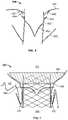
- FIG. 5Ais a bottom perspective view of a flange for use with a prosthetic heart valve.
- FIG. 5Bis a highly schematic cross-section of the prosthetic heart valve of FIG. 3A in a collapsed condition.
- FIG. 6is a highly schematic cross-section of the prosthetic heart valve of FIG. 3A in an expanded condition.
- FIG. 7is a highly schematic representation of the prosthetic heart valve of FIG. 3A implanted into a native tricuspid valve annulus.
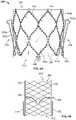
- FIG. 8Ais a side view of a prosthetic heart valve according to another embodiment of the disclosure.
- FIG. 8Bis a side view of the prosthetic heart valve of FIG. 8A in a different rotational position.
- the term “inflow end,” when used in connection with a prosthetic tricuspid heart valve,refers to the end of the heart valve closest to the right atrium when the heart valve is implanted in a patient
- the term “outflow end,” when used in connection with a prosthetic tricuspid heart valverefers to the end of the heart valve closest to the right ventricle when the heart valve is implanted in a patient.
- the terms “substantially,” “generally,” and “about”are intended to mean that slight deviations from absolute are included within the scope of the term so modified. Generally, materials described as being suitable for components in one embodiment of the disclosure may also be suitable for similar or identical components described in other embodiments.
- FIG. 1is a highly schematic cutaway representation of human heart 100 .
- the human heartincludes two atria and two ventricles: right atrium 112 and left atrium 122 , and right ventricle 114 and left ventricle 124 .
- Heart 100further includes aorta 110 and aortic arch 120 .
- mitral valve 130Disposed between left atrium 122 and left ventricle 124 is mitral valve 130 .
- Mitral valve 130also known as the bicuspid valve or left atrioventricular valve, is a dual-flap valve that opens as a result of increased pressure in left atrium 122 as it fills with blood. As left atrial pressure increases above that of left ventricle 124 , mitral valve 130 opens and blood passes into left ventricle 124 .
- Tricuspid valve 140disposed between right atrium 112 and right ventricle 114 is tricuspid valve 140 .
- Tricuspid valve 140also known as the right atrioventricular valve, is a three-flap valve that opens as a result of increased pressure in right atrium 112 as it fills with blood.
- tricuspid valve 140opens and blood passes into right ventricle 114 . Blood flows through heart 100 in the direction shown by arrows B.
- heart 100includes aortic valve 150 , which permits one-way flow of blood from left ventricle 124 to aorta 110 , and pulmonary valve 160 , which permits one-way flow of blood from right ventricle 114 to pulmonary artery 170 .
- a dashed arrow, labeled “TA”,indicates a transapical approach for implanting a prosthetic heart valve, in this case to replace tricuspid valve 140 . In transapical delivery, a small incision is made between the ribs and into the apex of right ventricle 114 to deliver the prosthetic heart valve to the target site.
- transapical deliverya small incision is made between the ribs and into the apex of right ventricle 114 to deliver the prosthetic heart valve to the target site.
- other approaches for implanting a prosthetic tricuspid valveare also possible.
- tricuspid valve 140may be approached via superior vena cava 180 or inferior vena cava 190 using any suitable access point including, for example, the femoral vein or the jugular vein.
- Still other delivery approachesmay be appropriate, for example including a trans-atrial approach, an axillary vein approach, or any other approach to accessing the right atrium, including a cut-down approach to gain direct access.
- FIG. 2Ais a schematic representation of native tricuspid valve 140 , with FIG. 2B illustrating certain associated structures.
- tricuspid valve 140typically includes three flaps or leaflets, including septal or medial leaflet 142 , anterior leaflet 144 , and posterior leaflet 146 , disposed between right atrium 112 and right ventricle 114 .
- Cord-like tendonsknown as chordae tendineae 148 , connect the three leaflets 142 , 144 , 146 , to papillary muscles 149 .
- heart 100typically includes three papillary muscles 149 in right ventricle 114 , more or fewer papillary muscles may be present.
- leaflets 142 , 144 , 146open, enabling blood to flow from higher pressure in right atrium 112 to lower pressure in right ventricle 114 .
- right ventricle 114contracts in ventricular systole, the increased blood pressure in the chamber pushes leaflets 142 , 144 , 146 to close, preventing the backflow of blood into right atrium 112 .
- leaflets 142 , 144 , 146attempt to evert to the low pressure regions.
- Chordae tendineae 148prevent the eversion by becoming tense, thus pulling on leaflets 142 , 144 , 146 and holding them in the closed position.
- FIG. 3Ais a bottom perspective view of a prosthetic heart valve 300 according to an aspect of the present disclosure.
- Prosthetic heart valve 300is shown in FIG. 3B viewing outflow end 312 , and in FIG. 3C viewing inflow end 310 .
- Prosthetic heart valve 300is a collapsible prosthetic heart valve designed to replace the function of the native tricuspid valve of a patient, such as native tricuspid valve 140 of FIGS. 1-2B .
- prosthetic heart valve 300may be suitable for use in replacing other valves, such as mitral valve 130 .
- prosthetic valve 300has a substantially cylindrical stent 350 and a flared flange 380 , which may be an atrial flange. While in some embodiments, stent 350 may have a substantially circular cross-section, other shapes, including an oval cross-section or a D-shaped cross-section, may be appropriate.
- FIG. 4Ais a side view of prosthetic heart valve 300 showing stent 350 with various related structures, such as flange 380 , omitted for clarity.
- Stent 350may be formed from biocompatible materials that are capable of self-expansion, such as, for example, shape-memory alloys including nitinol.
- Stent 350may include a plurality of struts 352 that form cells 354 connected to one another in one or more annular rows around the stent. Cells 354 may all be of substantially the same size around the perimeter and along the length of stent 350 . Alternatively, cells 354 near inflow end 310 may be larger than the cells near outflow end 312 , or vice versa.
- stent 350includes two annular rows of cells 354 , including a first annular row of cells 354 a adjacent inflow end 310 , and a second annular row of cells 354 b adjacent outflow end 312 .
- FIG. 4Ashows stent 350 as including nine substantially diamond shaped cells 354 in each row
- FIGS. 3A-Cshow the stent including twelve substantially diamond shaped cells in each row. It should be understood that more or fewer than nine or twelve cells may be provided in each row, and the cells may have shapes other than diamond shapes.
- Stent 350may be expandable to exert a radial force to assist with positioning and stabilizing prosthetic heart valve 300 in the annulus of native tricuspid valve 140 .
- FIG. 4Bis a highly schematic cross-section of prosthetic heart valve 300 .
- a valve assembly 360may be disposed within stent 350 , the valve assembly including a plurality of leaflets 362 that may be attached to a cuff 364 and/or to struts 352 of stent 350 .
- Leaflets 362replace the function of native tricuspid valve leaflets 142 , 144 , 146 described above with reference to FIGS. 2A-B . That is, leaflets 362 coapt with one another to function as a one-way valve.
- the valve assembly 360 of prosthetic heart valve 300may include three leaflets 362 , but it should be appreciated that more or fewer than three leaflets may be suitable.
- Cuff 364may cover part or all of an interior surface of stent 350 , and may provide various benefits, for example including decreasing or eliminating contact between leaflets 362 and stent 350 , which could otherwise cause damage to the leaflets. Cuff 364 may also assist in fixing leaflets 362 to stent 350 , for example using sutures that directly couple the leaflets to the cuff. Still further, cuff 364 may assist in creating a seal between prosthetic heart valve 300 and the annulus of native tricuspid valve 140 , to thereby limit paravalvular leak (“PV leak”) in which blood flows from right ventricle 114 to right atrium 112 between the prosthetic heart valve and the native tricuspid valve annulus.
- PV leakparavalvular leak
- Both cuff 364 and leaflets 362may be wholly or partly formed of any suitable biological material, such as bovine or porcine pericardium, or polymers, such as polytetrafluoroethylene (PTFE), urethanes and the like.
- Cuff 364may be positioned on the interior or luminal surface of stent 350 , on the abluminal surface of the stent, or on both surfaces.
- Valve assembly 360may be secured to stent 350 by suturing to struts 352 and/or to cuff 364 , or by using tissue glue, ultrasonic welding, or other suitable attachment methods.
- stent 350may include a plurality of commissure attachment features (“CAFs”) 366 to facilitate attachment of leaflets 362 to the stent.
- CAFscommissure attachment features
- CAFs 366are positioned on the outflow end 312 of stent 350 , extending in a direction away from inflow end 310 .
- each CAF 366may include a retainer 367 , as shown in FIG. 3A , extending therefrom.
- Retainers 367can have any shape, including substantially circular, and be configured to couple to a delivery device to prevent premature release or deployment of prosthetic heart valve 300 .
- CAFs 366are illustrated in FIG.
- the CAFscan have other suitable shapes, including one or more rows of eyelets formed in one or more columns, and may additional include different sized eyelets and/or elongated eyelets.
- Prosthetic heart valve 300may also include stabilization or securement features to assist in maintaining the prosthetic heart valve within the native valve annulus, for example including flange 380 , described in greater detail below, and stabilization or anchor arms 370 .
- anchor armsmay be referred to as stabilization arms instead, and the arms may provide a stabilization and/or an anchoring function.
- CAFs of the type described abovemay not be necessary.
- the prosthetic leafletsmay be directly attached to struts of the stent, instead of to a separate CAF feature.
- Prosthetic heart valve 300preferably includes three anchor arms 370 , corresponding to the three leaflets 142 , 144 , 146 of native tricuspid valve 140 .
- prosthetic heart valve 300may include more or fewer anchor arms 370 .
- anchor arms 370are spaced at substantially equal intervals around the circumference of stent 350 , although other relative spacing may be suitable.
- each anchor arm 370may include a first end 370 a coupled or otherwise attached to an apex of a first cell 354 in the second row of cells 354 b at outflow end 312 .
- Each anchor arm 370may also include a second end 370 b opposite first end 370 a , the second end being coupled or otherwise attached to an apex of a second cell 354 in the second row of cells 354 b at outflow end 312 , the first and second cells being circumferentially adjacent to each other.
- ends 370 a and 370 b of each anchor arm 370are coupled to the cell apices that are closest to the outflow end 312 of prosthetic heart valve 300 .
- the first and second ends 370 a , 370 bmay transition to elongated center portions 370 c , 370 d , respectively, that extend toward the inflow end 310 of stent 350 .
- Center portions 370 c , 370 dmay transition to a tip 370 e having a blunted and/or generally circular or oval shape.
- the tips 370 emay include optional additional features to reduce trauma to adjacent tissue which the trips may contact, including, as described in greater detail below, applying materials such as polymers, tissues, fabrics, or the like to the tips.
- Tip 370 emay have a width in a circumferential direction of stent 350 that is greater than the distance between center portions 370 c , 370 d.
- Anchor arms 370may be formed of any suitable material, and may be coupled to stent 350 in any suitable fashion, or otherwise may be formed integrally with the stent.
- anchor arms 370are formed of nitinol and are integral with stent 350 , the stent and anchor arms 370 being laser cut from the same structure. If anchor arms 370 are formed of a material having shape-memory properties, the anchor arms may be set (such as by heat setting) to have a desired shape and/or position in an unconstrained state.
- anchor arms 370are clipped or otherwise positioned over surfaces of the leaflets 142 , 144 , 146 of native tricuspid valve 140 , so that the native leaflets are positioned between the anchor arms and an exterior surface of stent 350 .
- each anchor arm 370is positioned in contact with the center of the corresponding native leaflet 142 , 144 , 146 .
- anchor arms 370are positioned at the centers of corresponding native leaflets 142 , 144 , 146 , the likelihood of the anchor arms interfering with chordae tendineae 148 may be reduced. As shown in FIG. 4A , about three cells 354 in the second row of cells 354 b may be positioned between each pair of circumferentially adjacent anchor arms 370 . However, if stent 350 includes a different number of cells, the spacing may be different. For example, in a twelve cell embodiment, such as that shown in FIGS. 3A-C , about four cells may be positioned between each pair of circumferentially adjacent anchor arms 370 . In some embodiments, such as that shown in FIG.
- anchor arms 370are attached to stent 350 centered between circumferentially adjacent CAFs 366 , such that, when implanted, the CAFs of prosthetic heart valve 300 are substantially aligned with the commissures of native valve leaflets 142 , 144 , 146 when anchor arms 370 are clipped over center portions of the corresponding native leaflets.
- anchor arms 370may clip over native leaflets 142 , 144 , 146 when prosthetic heart valve 300 is implanted in the annulus of tricuspid valve 140 .
- the blunted shape of tips 370 emay help to reduce the likelihood that anchor arms 370 would damage native tissue at or near tricuspid valve 140 .
- additional featuresmay be provided to further reduce the likelihood of anchor arms 370 damaging native tissue.
- anchor arms 370may include one or more layers of a buffer or other material.
- anchor arm 370is covered with a first layer 372 of buffer material that is sutured or otherwise coupled to the anchor arm.
- First layer 372may be one or more layers of tissue, for example bovine or porcine pericardium.
- anchor arm 370may be completely or substantially completely covered by first layer 372 , which may include two or more layers that sandwich the anchor arm therebetween.
- First layer 372can extend over both center portions 370 c , 370 d and over tip 370 e of anchor arms 370 .
- a second layer 374 of a buffer materialmay be provided on the tip 370 e of anchor arm 370 .
- the tip 370 e of anchor arm 370may be more likely to damage native tissue, and second layer 374 may further reduce the likelihood of such damage.
- second layer 374is formed from a biocompatible polymer fabric or sheet material, such as PTFE, and overlies first layer 372 .
- first layer 372is described as being formed of tissue
- second layer 374is described as being formed of a polymer fabric or sheet material, either layer may be formed of either material, or of a combination of both materials.
- second layer 374may be provided without first layer 372 , and in other embodiments, the first layer may be provided without the second layer.
- the first layer 372 and the second layer 374may increase the area of contact between anchor arm 370 and the corresponding native leaflets 142 , 144 , 146 , and may be softer than the center portions 370 c , 370 d and tip 370 e of the anchor arm, thus reducing the likelihood that the native tissue is damaged from interaction with the anchor arms.
- anchor arms 370are preferably made from a shape-memory alloy.
- the anchor arms 370may be set, for example by heat setting, to take the illustrated shape and/or position in the absence of applied forces.
- forcesmay be applied to anchor arms 370 and to prosthetic heart valve 300 generally to reduce the radial size and/or bulk of the prosthetic heart valve when in the collapsed condition, which may facilitate intravascular (or other minimally invasive) delivery of the prosthetic heart valve via a delivery device (not shown). For example, as shown in FIG.
- stent 350may be transitioned to the collapsed condition, with tips 370 e of anchor arms 370 being distorted or “flipped” to point away from inflow end 310 rather than toward the inflow end.
- Prosthetic heart valve 300may be maintained in the collapsed condition, for example by a surrounding sheath of a delivery device (not shown), as prosthetic heart valve 300 is delivered to native tricuspid valve 140 .
- prosthetic heart valve 300may be released from the delivery device. As the constraining forces of the surrounding sheath are removed from prosthetic heart valve 300 , it begins to transition to the expanded condition shown in FIG. 4B , while anchor arms 370 transition to their preset shape.
- anchor arms 370are shape-set so that their tips 470 e point toward inflow end 310 , the anchor arms revert to that shape when released from the delivery device. As the tips 370 e of anchor arms 370 transition from pointing away from inflow end 310 to pointing toward the inflow end, native tricuspid valve leaflets 142 , 144 , 146 are captured between the anchor arms and the abluminal surface of stent 350 . Distorting or flipping anchor arms 370 to point away from inflow end 310 while prosthetic heart valve 300 is maintained in the collapsed condition may reduce the profile of the collapsed valve. However, it should be understood that this flipping of anchor arms 370 is not required.
- the tips 370 e of anchor arms 370may instead be kept pointing toward inflow end 310 , which may slightly increase the radial profile of the collapsed valve, but also decrease the total longitudinal length of the collapsed valve, which may be desirable in some circumstances.
- anchor arms 370are shown in the figures as having a particular length, the lengths may be greater or smaller than shown. For example, if it is desired that anchor arms 370 only clip onto native leaflets 142 , 144 , 146 , the anchor arms may be relatively short. However, if it is desired that anchor arms 370 clip onto native leaflets 142 , 144 , 146 and also engage the native annulus for additional stabilization, the anchor arms may be relatively long. Still further, although anchor arms 370 are shown as being coupled to apices of two adjacent cells 354 in the second row 354 b , other attachment positions may be suitable.
- anchor arms 370may be attached to a single cell 354 in the second row 354 b , for example so that first and second ends 370 a , 370 b are positioned within a cell on either side of the apex. Further, anchor arms 370 may be attached to any desired portions of stent 350 in any suitable fashion. And while anchor arms 370 are shown as generally symmetrical, this is not necessary. For example, in some embodiments, different anchor arms 370 may have different lengths, may be attached at different locations (e.g. attached to cells in different rows), and may have unequal spacing around the perimeter of the stent.
- FIG. 4Aillustrates one type of stabilization feature in the form of anchor arms 370
- a second type of stabilization featurein the form of flange 380
- flange 380which may also be referred to as an atrial flare
- atrial flareis intended to be positioned in right atrium 112 adjacent the annulus of native tricuspid valve 140 , with the size and shape of the flange helping to prevent migration of prosthetic heart valve 300 into right ventricle 114 and to further assist in providing a seal against the annulus.
- Flange 380may be formed of a material braided to create various shapes and/or geometries to engage tissue.
- flange 380includes a plurality of braided strands or wires 386 arranged in three dimensional shapes.
- wires 386form a braided metal fabric that is resilient, collapsible and capable of heat treatment to substantially set a desired shape.
- shape-memory alloyssuch as nitinol.
- Wires 386may comprise various materials other than nitinol that have elastic and/or shape memory properties, such as spring stainless steel, tradenamed alloys such as Elgiloy® and Hastelloy®, CoCrNi alloys (e.g., tradename Phynox), MP35N®, CoCrMo alloys, or a mixture of metal and polymer fibers.
- the strand diameter, number of strands, and pitchmay be altered to achieve the desired shape and properties of flange 380 .
- the porosity of the braided fabricis preferably such as to not interfere with the flow of blood through prosthetic heart valve 300 when the leaflets 362 thereof are in the open position.
- Flange 380may include a plurality of groups of individual wires 386 that are bunched together at regular intervals around stent 350 to attach the flange to the stent.
- groups of individual wires 386are attached to portions of stent 350 where a first cell 354 in the first row of cells 354 a joins a circumferentially adjacent cell in the first row of cells.
- the number of bunches of individual wires 386 coupling flange 380 to stent 350is equal to the number of cells 354 in the first circumferential row of cells 354 a , although this one-to-one relationship is not a requirement.
- the individual wires 386 in a particular group or bunchmay be coupled together via a coupling tube 388 or other structure that is also attached to stent 350 .
- the groups of individual wires 386are shown in FIG. 5A as being coupled between adjacent cells 354 in the first row of cells 354 a , it should be understood that the groups of individual wires may instead be attached to other portions of stent 350 , for example between adjacent cells in the second row of cells 354 b , or to any desired apices of the cells.
- Flange 380may additionally or alternatively be coupled to stent 350 by sutures, ultrasonic welds, glue, adhesives, or other suitable means.
- coupling tubes 388 and other suitable structures for coupling flange 380 to stent 350are described in greater detail in U.S. Provisional Patent Application No. 62/745,528, titled “Braid Connections for Prosthetic Heart Valves” and filed on Oct. 15, 2018, the disclosure of which is hereby incorporated by reference herein.
- Flange 380may extend around the outside of stent 350 from the points at which the flange is connected to the stent to inflow end 310 of prosthetic heart valve 300 .
- the shape of flange 380 in an unconstrained conditionmay be generally disc-shaped or cylindrical, although other shapes including toroid-shaped, trumpet-shaped, elliptical, conical, and/or frustoconical may be suitable.
- Flange 380may be preset to take the desired shape in the absence of applied forces. As with stent 350 , flange 380 may be collapsed to a decreased profile to facilitate minimally invasive delivery.
- prosthetic heart valve 300may be transitioned from an expanded condition to a collapsed condition and maintained in the collapsed condition by a surrounding sheath of a delivery device.
- flange 380may collapse radially inwardly and become substantially cylindrical and/or significantly less flared than in the expanded condition.
- flange 380extends away from outflow end 312 , so that much, most, or all of the flange does not radially overlap with stent 350 , reducing the radial profile of prosthetic heart valve 300 when it is collapsed. It should be noted that, in FIG.
- prosthetic heart valve 300is illustrated with the tips 370 e of anchor arms 370 pointing toward inflow end 310 in the collapsed condition, which, as noted above, is an alternative to the collapsed condition shown in FIG. 4C .
- the individual bunches of wires 386 of flange 380may extend at an angle from stent 350 based at least in part by the angle at which coupling tubes 388 extend from the stent.
- the angle of each bunch of wires 386may be substantially the same which my assist in forming a generally circular flange 380 .
- One way to achieve such an oval shape for flange 380is by providing different angles of coupling tubes 388 around the perimeter of the stent to create an oval shape.
- Exemplary angles for coupling tubes 380may include, for example, about 30 degrees, about 45 degrees, or about 60 degrees relative to stent 350 , although other angles may be suitable.
- FIG. 5Aillustrates flange 380 without any additional materials covering or otherwise incorporated into the flange.
- one or more surfaces of flange 380may be covered by material(s), such as tissue and/or fabric, including any of the materials described above as being suitable for leaflets 362 and/or cuff 364 .
- the surface of flange 380 intended to contact the annulus of native tricuspid valve 140may be partially or completely covered with tissue and/or fabric, which may help prevent PV leak and/or facilitate tissue ingrowth to further secure prosthetic heart valve 300 after implantation.
- tissue and/or fabricmay be provided on both surfaces of flange 380 .
- tissue and/or fabric layersmay be provided between the opposing surfaces of flange 380 , particularly when the flange is folded over itself so that an interior space is provided between the opposing surfaces of the flange.
- FIGS. 3A-Calso illustrate a third type of stabilization feature in the form of cleats or barbs 390 .
- barbs 390are positioned at discrete locations in the circumferential direction around the outer perimeter of stent 350 , the barbs including sharp tips that point radially outwardly from the longitudinal center of the stent.
- Barbs 390may extend radially outwardly from stent 350 a short distance compared to the distance which flange 380 extends radially outwardly from the stent. If included, barbs 390 may function to pierce or otherwise engage native tissue at or near the annulus of native tricuspid valve 140 , further stabilizing prosthetic heart valve 300 upon implantation.
- barbs 390need not be long in order to effectively engage the native tissue.
- barbs 390are formed integrally with the stent, although in other embodiments the barbs could be formed separately and attached to the stent.
- Barbs 390may be provided in any desired position and in any desired number on stent 350 .
- one or more barbs 390may be provided for each cell 354 in the first row of cells 354 a , including at positions at either or both apices of each cell, or at positions where adjacent cells in the first row of cells join one another.
- One or more barbs 390may also be provided for each cell 354 in the second row of cells 354 b , including at either or both apices of each cell, or at positions where adjacent cells in the second row of cells join one another. In yet another example, barbs 390 may be provided on less than each cell 354 in the first row of cells 354 a and/or the second row of cells 354 b . Barbs 390 may extend substantially orthogonally to the center longitudinal axis of stent 350 , or may otherwise be flared or curved in any desired direction.
- one or more barbs 390may curve between stent 350 and the sharp tip of the barb in a direction toward inflow end 310 , since prosthetic heart valve 300 may experience the largest force in the direction of right atrium 112 when leaflets 362 coapt with one another and right ventricle 114 contracts.
- the barbsmay be able to fold or otherwise readily collapse when prosthetic heart valve 300 is transitioned into the collapsed condition, which may reduce the likelihood of the barbs damaging components of the prosthetic heart valve and/or structures of the delivery device.
- other curvaturesmay be provided as desired, or omitted entirely.
- a curvature of barbs 390may be chosen that does not significantly restrict the ability to re-sheath prosthetic heart valve 300 into a delivery device if, upon partial deployment, it is determined that the prosthetic heart valve should be re-collapsed into the delivery device so that the prosthetic heart valve may be repositioned and re-deployed. Still further, although barbs 390 are shown and described as being integral with or otherwise attached to stent 350 , barbs may be additionally or alternatively provided on flange 380 .
- barbs 390may be integrally formed with the braid of flange 380 , or may be separately attached thereto, particularly on the surface of the flange intended to contact the annulus of native tricuspid valve 140 . If barbs 390 are provided on flange 380 , as with barbs on stent 350 , they may be provided in any desired number and at any desired locations expected to contact native tissue to provide increased stabilization of prosthetic heart valve 300 . If barbs 390 are provided on flange 380 , they may be less stiff than if barbs are provided on stent 350 , although this is not required.
- One way to provide barbs 390 on flange 380may be to shape-set, for example by heating, a wire in a general U-shape, and suture the wire to the braid of the flange.
- barbs 390are described above as being attached to stent 350 and/or flange 380 , it may be preferable instead to provide the barbs on coupling tubes 388 (or other suitable connectors that couple the flange to the stent), with the sharp end of the barbs pointing radially outwardly from the longitudinal center of the stent, with any desired curvature as described above.
- the barbs 390are described as being sharp, which may assist in piercing tissue to provide increased stability, the barbs may alternatively be blunted, with the blunted barbs providing increased friction to provide increased stability.
- the barbs 390are generally shown as being symmetrically placed around the perimeter of the prosthetic heart valve 300 , such symmetry is not necessary.
- barbs 390could be placed or omitted from strategic locations on the prosthetic heart valve 300 depending on what anatomical structures are anticipated to be positioned adjacent those strategic locations. For example, it may be desirable to omit barbs 390 from locations on the prosthetic heart valve 300 expected to be adjacent coronary arteries.
- FIG. 6is a schematic longitudinal cross-section of prosthetic heart valve 300 in the expanded condition, illustrating the three stabilization features described above, including anchor arms 370 , flange 380 , and barbs 390 .
- FIG. 6additionally illustrates a feature for mitigating PV leak in the form of parachute 400 .
- Parachute 400is also illustrated in FIGS. 3A-B .
- Parachute 400may be formed from tissue and/or fabric, including any of the materials described above in connection with leaflets 362 and/or cuff 364 .
- parachute 400is a substantially rectangular strip of tissue that has a first edge 402 coupled to the surface of flange 380 intended to contact the annulus of native tricuspid valve 140 .
- First edge 402may be coupled along most or all of its length to flange 380 , for example by a continuous suture line.
- Parachute 400may include a second edge 404 opposite first edge 402 that is also coupled to the surface of flange 380 intended to contact the annulus of native tricuspid valve 140 .
- second edge 404may be coupled to flange 380 only at spaced locations along its length, for example by individual suture stitches.
- second edge 404is coupled to flange 380 at positions radially inward from first edge 402 .
- one or more pockets of spaceare created between parachute 400 and adjacent portions of flange 380 and/or stent 350 , with openings to those pockets being defined between the intermittent connections of second edge 404 to flange 380 , the openings facing the outer surface of stent 350 .
- prosthetic heart valve 300is implanted and leaflets 362 are coapted so that the valve is closed, blood flowing in the retrograde direction between the outside of stent 350 and the native valve annulus may enter the openings to the pocket(s), which may cause parachute 400 to billow outwardly and create a better seal between prosthetic heart valve 300 and the annulus of native tricuspid valve 140 , reducing or eliminating PV leak.
- parachute 400is described above as a single piece of rectangular material, other options may be suitable.
- the materialneed not be rectangular, need not be a single continuous piece, and could take any shape and/or include any number of individual pieces joined together that allow for the parachute functionality described above.
- parachute 400is shown as being wrapped around the entire perimeter of stent 350 , in some embodiments, a single section of parachute or multiple individual sections of parachute may be provided along less than the entire perimeter of the stent, for example in regions particularly susceptible to PV leak.
- parachute 400is illustrated in FIGS. 3A-B and 6 as being coupled to flange 380 , the parachute may instead be attached to the exterior surface of stent 350 near the flange.
- Parachute 400may be attached to stent 350 in substantially the same way as described above for attachment to flange 380 , with first edge 402 continuously or substantially continuously attached to the stent to form a closed side of the parachute, and second edge 404 attached to the stent only at intermittent locations to define openings into which blood may flow.
- first edge 402 of parachute 400may be coupled to flange 380 with second edge 404 coupled to stent 350 .
- one parachute 400may be provided on flange 380 , with a second parachute provided on the exterior surface of stent 350 .
- the intermittent attachments of second edge 404 to flange 380 or stent 350may function to stop parachute 400 from everting by action of retrograde blood flow.
- the parachutemay be able to resist everting even if second edge 404 is not directly attached to the flange or stent.
- parachute 400may be provided on stent 350 and/or flange 380 , it should also be understood that more than one parachute may be provided on the stent, and more than one parachute may be provided on the flange.
- additional parachutes 400may increase the resistance to PV leak, additional material typically increases the profile of prosthetic heart valve 300 in the collapsed condition, and it is generally desirable to limit the size of the profile in the collapsed condition. Still further, it should be understood that, when parachute 400 is coupled to flange 380 , an intervening layer of material may be positioned between the parachute and the surface of flange 380 to which the parachute is coupled, which may provide a better seal if the spacing of the wires 386 of the flange would otherwise allow blood to flow through the flange. If, on the other hand, parachute 400 is coupled to stent 350 , cuff 364 may serve a similar purpose as the above-mentioned intervening layer of material.
- FIG. 7is a highly schematic representation of prosthetic heart valve 300 implanted into the valve annulus VA of tricuspid valve 140 .
- anchor arms 370are clipped around the native leaflets of tricuspid valve 140 .
- FIG. 7it should be appreciated that a third anchor arm and the third native leaflet are omitted from FIG. 7 .
- Barbs 390are also illustrated as piercing into valve annulus VA to better secure prosthetic heart valve 300 within the valve annulus.
- Flange 380is able to closely conform to the tissue surfaces at and adjacent to valve annulus VA at least in part due to the flexibility provided by forming the flange from braided nitinol, although other configurations and other materials may be able to provide similar conformability.
- parachute 400is positioned at or adjacent valve annulus VA so that, if blood flows from right ventricle 114 toward right atrium 112 between the outer surface of stent 350 and the inner surface of the valve annulus, that blood will tend to enter the pocket(s) of the parachute and billow the parachute outwardly to reduce or eliminate blood passing into the right atrium from the right ventricle around the outside of prosthetic heart valve 300 .
- prosthetic heart valve 300is preferably intended for replacement of tricuspid valve 140 , although it may be effective at replacing native mitral valve 130 , with or without alterations such as providing two anchor arms to clip over the two mitral valve leaflets instead of three anchor arms to clip over the three tricuspid valve leaflets.
- certain elements of prosthetic heart valve 300also make it particularly suited for replacing tricuspid valve 140 .
- right ventricle 114is generally smaller than left ventricle 124 , at least in part due to the fact that the left ventricle pumps blood to the entire body, whereas the right ventricle pumps blood only to the lungs.
- prosthetic heart valve 300may include features that allow it to extend only a relatively small distance into right ventricle 114 .
- anchor arms 370are attached to stent 350 at outflow end 312 , so that there is little or no additional structure beyond the point of attachment of the anchor arms to the stent.
- anchor arms 370clip over the native leaflets 142 , 144 , 146 of tricuspid valve 140 , there is little or no additional structure extending beyond the native leaflets into right ventricle 114 .
- RVOTright ventricular outflow tract
- LVOTleft ventricular outflow tract
- prosthetic tricuspid valve 300may need to be taken into account in prosthetic tricuspid valve 300 .
- the coronary sinusflows into right atrium 112 , and prosthetic tricuspid valve 300 does not obstruct the coronary sinus.
- prosthetic tricuspid valve 300does not obstruct the coronary sinus.
- AVatrioventricular
- anchor arms 370 of prosthetic heart valve 300are shown and described above as being coupled to outflow end 312 of stent 350 , in other embodiments, anchor arms having similar functionality may be coupled to the stent near inflow end 310 , or to flange 380 .
- FIG. 8Aillustrates stent 350 in the same view as FIG. 4A , with anchor arms 370 ′ coupled to inflow end 310 of stent 350 .
- FIG. 8Bshows stent 350 of FIG. 8A rotated about 90 degrees about the longitudinal axis of the stent.
- Anchor arms 370 ′may each include a first end 370 a ′ coupled or otherwise attached to an apex of a first cell 354 in the first row of cells 354 a at inflow end 310 , and a second end 370 b ′ opposite the first end coupled or otherwise attached to an apex of a second cell in the first row of cells at the inflow end, the first and second cells being circumferentially adjacent to each other.
- the first and second ends 370 a ′, 370 b ′may transition to elongated center portions 370 c ′, 370 d ′, respectively, that extend toward the outflow end 312 of stent 350 .
- Center portions 370 c ′, 370 d ′may hook back and join one another to form a tip 370 e ′ that points toward inflow end 310 , the tip having a blunted and/or generally circular or oval shape.
- each anchor arm 370 ′forms a recess or gap between its tip 370 e ′ and adjacent portions of its center portions 370 c ′, 370 d ′, with the recess or gap intended to receive a portion of the native leaflets 142 , 144 , 146 of tricuspid valve 140 therein.
- anchor arms 370may generally apply with equal force to anchor arms 370 ′.
- anchor arms 370 ′may be formed of any of the materials described above for anchor arms 370 , and may include additional tissue and/or fabric layers similar or identical to those described in connection with anchor arms 370 .
- the placement of anchor arms 370 ′ around the circumference of stentmay also be similar or identical to that described in connection with anchor arms 370 .
- prosthetic heart valve 300may include three anchor arms 370 ′ spaced at equal intervals around the circumference of the stent, with the anchor arms functioning to grasp portions of native leaflets 142 , 144 , 146 , preferably at or near their centers, to stabilize the prosthetic heart valve within the annulus of native tricuspid valve 140 , and further to reduce movement of the native leaflets. Still further, as with anchor arms 370 , the positioning of anchor arms 370 ′ is such that, when prosthetic heart valve 300 is implanted and the anchor arms clip over or otherwise grasp native leaflets 142 , 144 , 146 , there is little or no structure of the prosthetic heart valve positioned beyond the native leaflets toward right ventricle 114 .
- a prosthetic heart valve 300 incorporating anchor arms 370 ′may also include one or more of flange 380 , barbs 390 , and parachute 400 described above.
- anchor arms 370 ′may also include one or more of flange 380 , barbs 390 , and parachute 400 described above.
- FIGS. 8A-Bone particular exemplary structure for anchor arms 370 ′ is shown in FIGS. 8A-B , modifications may be suitable.
- the portion of each anchor arm that hooks back toward inflow end 310is illustrated as having a length that is small in relation to the remainder of center portions 370 c ′, 370 d ′, it should be understood that these portions may in some embodiments extend a greater distance back toward the inflow end.
- center portions 370 c ′, 370 d ′may extend from inflow end 310 toward outflow end 312 , flip or otherwise hook back toward inflow end 310 , and extend a greater distance than shown in FIGS. 8A-B back toward the inflow end prior to transitioning into tip 370 e ′.
- a larger gap or recessmay be provided to receive native leaflets 142 , 144 , 146 .
- anchor arms 370 ′are illustrated as coupled to the inflow end 310 of stent 350 , if flange 380 is included in the device, the anchor arms may instead be coupled to the surface of the flange intended to contact the native valve annulus of tricuspid valve 140 , preferably at a position near the connection between the flange and the stent.
- Prosthetic heart valve 300is described above as including anchor arms 370 (or anchor arms 370 ′), flange 380 , barbs 390 , and parachute 400 . However, it should be understood that each feature provides one or more particular functions, and any one of those features may be used in any combination with any one or more of the other features.
- prosthetic heart valve 300may include anchor arms 370 , flange 380 , and parachute 400 , but omit barbs 390 .
- a prosthetic heart valvecomprises: a stent having a collapsed condition, an expanded condition, an inflow end, and an outflow end;
- valve assemblydisposed within the stent
- a flangecomprising a plurality of braided wires, the flange being coupled to the stent and positioned adjacent the inflow end of the stent in the expanded condition of the stent;
- each anchor armhaving a first end coupled to the stent adjacent the outflow end of the stent, a second end coupled to the stent adjacent the outflow end of the stent, and center portions extending from the first and second ends toward the inflow end of the stent, the center portions being joined together to form a tip pointing toward the inflow end of the stent in the expanded condition of the stent;
- the stentincludes a first plurality of cells arranged in a first circumferential row adjacent the inflow end of the stent, and a second plurality of cells arranged in a second circumferential row adjacent the outflow end of the stent;
- each of the plurality of anchor armsis coupled to a respective first cell in the second circumferential row;
- each of the plurality of anchor armsis coupled to a respective second cell in the second circumferential row;
- the first cellis circumferentially adjacent the second cell;
- the stentis formed integrally with the plurality of anchor arms;
- the plurality of anchor armsincludes three anchor arms spaced at substantially equal intervals around a perimeter of the stent;
- each of the anchor armsis at least partially covered by a first layer of material
- the first layer of materialis formed of tissue
- each of the anchor armsis fully covered by the first layer of material
- the first layer of materialcovers the tips of the anchor arms, and a second layer of material covers the first layer of material;
- the first layer of materialis formed of tissue and the second layer of material is formed of fabric; and/or
- the flangeis coupled to the stent by coupling tubes positioned adjacent the inflow end of the stent;
- the coupling tubesinclude barbs having tips that extend radially away from a center longitudinal axis of the stent;
- the flangeincludes a first surface adapted to contact a portion of a native valve annulus of a patient when the prosthetic heart valve is in an implanted condition, and a second surface opposite the first surface;
- a strip of materialcoupled to the prosthetic heart valve, the strip of material extending around a perimeter of the stent adjacent the inflow end of the stent;
- the strip of materialincludes a first edge coupled to the first surface of the flange, and a second edge opposite the first edge, the second edge being positioned nearer a center longitudinal axis of the stent than is the first edge in the expanded condition of the stent, the second edge being coupled to the first surface of the flange at intermittent locations spaced apart from each other; and/or
- the first edgeis substantially continuously coupled to the first surface of the flange so that at least one pocket is formed between the first strip of material and the first surface of the flange, the at least one pocket including a plurality of openings to the at least one pocket between the intermittent locations of attachment of the second edge to the first surface of the flange;
- the strip of materialincludes a first edge coupled to the first surface of the flange, and a second edge opposite the first edge, the second edge being positioned nearer a center longitudinal axis of the stent than is the first edge in the expanded condition of the stent, the second edge being coupled to the stent at intermittent locations spaced apart from each other; and/or
- the first edgeis substantially continuously coupled to the first surface of the flange so that at least one pocket is formed between the first strip of material and the first surface of the flange, the at least one pocket including a plurality of openings to the at least one pocket between the intermittent locations of attachment of the second edge to the stent;
- the strip of materialincludes a first edge coupled to stent, and a second edge opposite the first edge, the second edge being positioned nearer the outflow end of the stent than is the first, the second edge being coupled to the stent at intermittent locations spaced apart from each other; and/or
- the first edgeis substantially continuously coupled to the stent so that at least one pocket is formed between the first strip of material and stent, the at least one pocket including a plurality of openings to the at least one pocket between the intermittent locations of attachment of the second edge to the stent.
Landscapes
- Health & Medical Sciences (AREA)
- Biomedical Technology (AREA)
- Engineering & Computer Science (AREA)
- Life Sciences & Earth Sciences (AREA)
- Cardiology (AREA)
- Veterinary Medicine (AREA)
- Heart & Thoracic Surgery (AREA)
- Animal Behavior & Ethology (AREA)
- General Health & Medical Sciences (AREA)
- Public Health (AREA)
- Surgery (AREA)
- Oral & Maxillofacial Surgery (AREA)
- Transplantation (AREA)
- Vascular Medicine (AREA)
- Medical Informatics (AREA)
- Molecular Biology (AREA)
- Nuclear Medicine, Radiotherapy & Molecular Imaging (AREA)
- Prostheses (AREA)
Abstract
Description
Claims (22)
Priority Applications (2)
| Application Number | Priority Date | Filing Date | Title |
|---|---|---|---|
| US16/705,355US11471277B2 (en) | 2018-12-10 | 2019-12-06 | Prosthetic tricuspid valve replacement design |
| US17/930,227US20230000621A1 (en) | 2018-12-10 | 2022-09-07 | Prosthetic Tricuspid Valve Replacement Design |
Applications Claiming Priority (2)
| Application Number | Priority Date | Filing Date | Title |
|---|---|---|---|
| US201862777298P | 2018-12-10 | 2018-12-10 | |
| US16/705,355US11471277B2 (en) | 2018-12-10 | 2019-12-06 | Prosthetic tricuspid valve replacement design |
Related Child Applications (1)
| Application Number | Title | Priority Date | Filing Date |
|---|---|---|---|
| US17/930,227DivisionUS20230000621A1 (en) | 2018-12-10 | 2022-09-07 | Prosthetic Tricuspid Valve Replacement Design |
Publications (2)
| Publication Number | Publication Date |
|---|---|
| US20200179109A1 US20200179109A1 (en) | 2020-06-11 |
| US11471277B2true US11471277B2 (en) | 2022-10-18 |
Family
ID=69024699
Family Applications (2)
| Application Number | Title | Priority Date | Filing Date |
|---|---|---|---|
| US16/705,355Active2040-03-25US11471277B2 (en) | 2018-12-10 | 2019-12-06 | Prosthetic tricuspid valve replacement design |
| US17/930,227PendingUS20230000621A1 (en) | 2018-12-10 | 2022-09-07 | Prosthetic Tricuspid Valve Replacement Design |
Family Applications After (1)
| Application Number | Title | Priority Date | Filing Date |
|---|---|---|---|
| US17/930,227PendingUS20230000621A1 (en) | 2018-12-10 | 2022-09-07 | Prosthetic Tricuspid Valve Replacement Design |
Country Status (3)
| Country | Link |
|---|---|
| US (2) | US11471277B2 (en) |
| EP (1) | EP3893804B1 (en) |
| WO (1) | WO2020123267A1 (en) |
Families Citing this family (12)
| Publication number | Priority date | Publication date | Assignee | Title |
|---|---|---|---|---|
| US20140277427A1 (en)* | 2013-03-14 | 2014-09-18 | Cardiaq Valve Technologies, Inc. | Prosthesis for atraumatically grasping intralumenal tissue and methods of delivery |
| WO2020114619A1 (en)* | 2018-12-04 | 2020-06-11 | Medtronic Bakken Research Center B.V. | Prosthetic heart valve |
| IL319705A (en) | 2020-02-06 | 2025-05-01 | Laplace Interventional Inc | Transcatheter heart valve prosthesis assembled inside heart chambers or blood vessels |
| CN111904664B (en)* | 2020-08-25 | 2025-06-24 | 上海臻亿医疗科技有限公司 | A tricuspid valve prosthesis |
| DE102021000811A1 (en) | 2021-02-10 | 2022-08-11 | Devie Medical Gmbh | Drug-releasing heart valve prosthesis, which compartmentalizes infected tissue structures in the heart or prevents postoperative infection |
| CN113730036A (en)* | 2021-09-30 | 2021-12-03 | 宁波健世科技股份有限公司 | Heart valve prosthesis capable of being anchored with autologous valve leaflet |
| US11510777B1 (en) | 2022-02-10 | 2022-11-29 | Laplace Interventional Inc. | Prosthetic heart valves |
| CN115068172B (en)* | 2022-07-12 | 2024-03-12 | 上海以心医疗器械有限公司 | Artificial heart valve support and heart valve prosthesis |
| US11712336B1 (en) | 2022-07-20 | 2023-08-01 | Laplace Interventional Inc. | Prosthetic heart valves |
| CN119097468A (en)* | 2023-06-08 | 2024-12-10 | 宁波健世科技股份有限公司 | A valve replacement system that facilitates the capture of valve leaflets |
| CN118924496A (en)* | 2024-08-26 | 2024-11-12 | 上海以心医疗器械有限公司 | Valve prosthesis |
| US12376963B1 (en) | 2025-02-11 | 2025-08-05 | Laplace Interventional Inc. | Prosthetic heart valves |
Citations (228)
| Publication number | Priority date | Publication date | Assignee | Title |
|---|---|---|---|---|
| US3657744A (en) | 1970-05-08 | 1972-04-25 | Univ Minnesota | Method for fixing prosthetic implants in a living body |
| US4275469A (en) | 1979-12-13 | 1981-06-30 | Shelhigh Inc. | Prosthetic heart valve |
| US4491986A (en) | 1976-05-12 | 1985-01-08 | Shlomo Gabbay | Heart valve |
| US4759758A (en) | 1984-12-07 | 1988-07-26 | Shlomo Gabbay | Prosthetic heart valve |
| US4878906A (en) | 1986-03-25 | 1989-11-07 | Servetus Partnership | Endoprosthesis for repairing a damaged vessel |
| US4922905A (en) | 1985-11-30 | 1990-05-08 | Strecker Ernst P | Dilatation catheter |
| US4994077A (en) | 1989-04-21 | 1991-02-19 | Dobben Richard L | Artificial heart valve for implantation in a blood vessel |
| WO1991017720A1 (en) | 1990-05-18 | 1991-11-28 | Henning Rud Andersen | A valve prosthesis for implantation in the body and a catheter for implantating such valve prosthesis |
| US5411552A (en) | 1990-05-18 | 1995-05-02 | Andersen; Henning R. | Valve prothesis for implantation in the body and a catheter for implanting such valve prothesis |
| US5415664A (en) | 1994-03-30 | 1995-05-16 | Corvita Corporation | Method and apparatus for introducing a stent or a stent-graft |
| US5480423A (en) | 1993-05-20 | 1996-01-02 | Boston Scientific Corporation | Prosthesis delivery |
| WO1997016133A1 (en) | 1995-11-01 | 1997-05-09 | Biocompatibles Limited | Braided stent |
| EP0850607A1 (en) | 1996-12-31 | 1998-07-01 | Cordis Corporation | Valve prosthesis for implantation in body channels |
| WO1998032412A2 (en) | 1997-01-24 | 1998-07-30 | Scimed Life Systems Inc | Bistable spring construction for a stent and other medical apparatus |
| US5843167A (en) | 1993-04-22 | 1998-12-01 | C. R. Bard, Inc. | Method and apparatus for recapture of hooked endoprosthesis |
| US5855601A (en) | 1996-06-21 | 1999-01-05 | The Trustees Of Columbia University In The City Of New York | Artificial heart valve and method and device for implanting the same |
| WO1999013801A1 (en) | 1997-09-16 | 1999-03-25 | Zadno Azizi Gholam Reza | Body fluid flow control device |
| US5935163A (en) | 1998-03-31 | 1999-08-10 | Shelhigh, Inc. | Natural tissue heart valve prosthesis |
| US5961549A (en) | 1997-04-03 | 1999-10-05 | Baxter International Inc. | Multi-leaflet bioprosthetic heart valve |
| US6045576A (en) | 1997-09-16 | 2000-04-04 | Baxter International Inc. | Sewing ring having increased annular coaptation |
| EP1000590A1 (en) | 1998-11-09 | 2000-05-17 | Cordis Corporation | An improved stent which is easly recaptured and repositioned within the body |
| US6077297A (en) | 1993-11-04 | 2000-06-20 | C. R. Bard, Inc. | Non-migrating vascular prosthesis and minimally invasive placement system therefor |
| DE19857887A1 (en) | 1998-12-15 | 2000-07-06 | Fraunhofer Ges Forschung | Anchoring support for a heart valve prosthesis comprises a single-piece component which is formed of rod shaped elements made of a memory metal, and has at least in part a lattice structure |
| US6090140A (en) | 1999-02-17 | 2000-07-18 | Shelhigh, Inc. | Extra-anatomic heart valve apparatus |
| WO2001028459A1 (en) | 1999-10-21 | 2001-04-26 | Scimed Life Systems, Inc. | Implantable prosthetic valve |
| WO2001049213A2 (en) | 1999-12-31 | 2001-07-12 | Advanced Bio Prosthetic Surfaces, Ltd. | Endoluminal cardiac and venous valve prostheses and methods of manufacture and delivery thereof |
| US6264691B1 (en) | 1999-04-23 | 2001-07-24 | Shlomo Gabbay | Apparatus and method for supporting a heart valve |
| WO2001054625A1 (en) | 2000-01-31 | 2001-08-02 | Cook Biotech Incorporated | Stent valves and uses of same |
| WO2001056500A2 (en) | 2000-02-03 | 2001-08-09 | Cook Incorporated | Implantable vascular device |
| WO2001076510A2 (en) | 2000-04-06 | 2001-10-18 | Edwards Lifesciences Corporation | Minimally-invasive heart valves and methods of use |
| US20020036220A1 (en) | 2000-09-26 | 2002-03-28 | Shlomo Gabbay | Curved implantable sheath and method of making same |
| US6368348B1 (en) | 2000-05-15 | 2002-04-09 | Shlomo Gabbay | Annuloplasty prosthesis for supporting an annulus of a heart valve |
| WO2002036048A1 (en) | 2000-10-31 | 2002-05-10 | Jacques Seguin | Tubular support for setting, by percutaneous route, a substitution cusp |
| WO2002047575A2 (en) | 2000-12-15 | 2002-06-20 | Angiomed Gmbh & Co. Medizintechnik Kg | Stent with valve |
| US6419695B1 (en) | 2000-05-22 | 2002-07-16 | Shlomo Gabbay | Cardiac prosthesis for helping improve operation of a heart valve |
| WO2002067782A2 (en) | 2001-02-26 | 2002-09-06 | Ev3 Peripheral, Inc. | Implant delivery system with interlock |
| US6468660B2 (en) | 2000-12-29 | 2002-10-22 | St. Jude Medical, Inc. | Biocompatible adhesives |
| US20030023303A1 (en) | 1999-11-19 | 2003-01-30 | Palmaz Julio C. | Valvular prostheses having metal or pseudometallic construction and methods of manufacture |
| US6517576B2 (en) | 2000-12-11 | 2003-02-11 | Shlomo Gabbay | Implantable patch prosthesis having one or more cusps for improved competency |
| US20030050694A1 (en) | 2001-09-13 | 2003-03-13 | Jibin Yang | Methods and apparatuses for deploying minimally-invasive heart valves |
| US6533810B2 (en) | 1995-11-27 | 2003-03-18 | Schneider (Europe) Ag | Conical stent |
| WO2003047468A1 (en) | 2001-10-11 | 2003-06-12 | Percutaneous Valve Technologies | Implantable prosthetic valve |
| US6582464B2 (en) | 2000-05-03 | 2003-06-24 | Shlomo Gabbay | Biomechanical heart valve prosthesis and method for making same |
| US20030130726A1 (en) | 1999-09-10 | 2003-07-10 | Thorpe Patricia E. | Combination valve and stent for treating vascular reflux |
| US6623518B2 (en) | 2001-02-26 | 2003-09-23 | Ev3 Peripheral, Inc. | Implant delivery system with interlock |
| US6685625B2 (en) | 2000-09-26 | 2004-02-03 | Shlomo Gabbay | Curved implantable sheath and method of making same |
| US6716244B2 (en) | 2000-12-20 | 2004-04-06 | Carbomedics, Inc. | Sewing cuff assembly for heart valves |
| US6719789B2 (en) | 1993-11-01 | 2004-04-13 | 3F Therapeutics, Inc. | Replacement heart valve |
| US20040111111A1 (en) | 2002-12-10 | 2004-06-10 | Scimed Life Systems, Inc. | Intravascular filter membrane with shape memory |
| FR2850008A1 (en) | 2003-01-17 | 2004-07-23 | Daniel Roux | Vascular prosthesis has tube and collar for adapting to blood vessel ends of different diameters |
| US6783556B1 (en) | 2000-09-26 | 2004-08-31 | Shlomo Gabbay | System and method for making a calotte-shaped implantable sheath |
| US6790230B2 (en) | 2001-04-30 | 2004-09-14 | Universitatsklinikum Freiburg | Vascular implant |
| US20040210304A1 (en) | 1999-11-17 | 2004-10-21 | Corevalve, S.A. | Prosthetic valve for transluminal delivery |
| US6814746B2 (en) | 2002-11-01 | 2004-11-09 | Ev3 Peripheral, Inc. | Implant delivery system with marker interlock |
| US6830584B1 (en) | 1999-11-17 | 2004-12-14 | Jacques Seguin | Device for replacing a cardiac valve by percutaneous route |
| US20040260389A1 (en) | 2003-04-24 | 2004-12-23 | Cook Incorporated | Artificial valve prosthesis with improved flow dynamics |
| US6869444B2 (en) | 2000-05-22 | 2005-03-22 | Shlomo Gabbay | Low invasive implantable cardiac prosthesis and method for helping improve operation of a heart valve |
| US20050096726A1 (en) | 2000-05-30 | 2005-05-05 | Jacques Sequin | Noncylindrical stent deployment system for treating vascular bifurcations |
| US20050137682A1 (en) | 2003-12-22 | 2005-06-23 | Henri Justino | Stent mounted valve |
| US20050137695A1 (en) | 2003-12-23 | 2005-06-23 | Sadra Medical | Replacement valve and anchor |
| US20050137697A1 (en) | 2003-12-23 | 2005-06-23 | Amr Salahieh | Leaflet engagement elements and methods for use thereof |
| WO2005070343A1 (en) | 2003-12-23 | 2005-08-04 | Laboratoires Perouse | Kit which is intended to be implanted in a conduit |
| US20050203605A1 (en) | 2004-03-15 | 2005-09-15 | Medtronic Vascular, Inc. | Radially crush-resistant stent |
| US6951573B1 (en) | 2001-12-22 | 2005-10-04 | Dilling Emery W | Prosthetic aortic valve |
| EP1584306A1 (en) | 1999-02-02 | 2005-10-12 | Bard Peripheral Vascular, Inc. | Partial encapsulation of stents using bands |
| FR2847800B1 (en) | 2002-11-28 | 2005-10-14 | Perouse Laboratoires | INTERCHANGEABLE PROTHETIC VALVE |
| US20050240200A1 (en) | 2004-04-23 | 2005-10-27 | Bjarne Bergheim | Method and system for cardiac valve delivery |
| US20050256566A1 (en) | 2004-05-03 | 2005-11-17 | Shlomo Gabbay | Apparatus and method for improving ventricular function |
| EP1598031A2 (en) | 1998-03-04 | 2005-11-23 | Boston Scientific Limited | Stent having variable properties |
| EP1360942B1 (en) | 2002-05-11 | 2005-12-14 | Willy Rüsch GmbH | Stent |
| US20060008497A1 (en) | 2004-07-09 | 2006-01-12 | Shlomo Gabbay | Implantable apparatus having improved biocompatibility and process of making the same |
| US7018406B2 (en) | 1999-11-17 | 2006-03-28 | Corevalve Sa | Prosthetic valve for transluminal delivery |
| US20060074484A1 (en) | 2004-10-02 | 2006-04-06 | Huber Christoph H | Methods and devices for repair or replacement of heart valves or adjacent tissue without the need for full cardiopulmonary support |
| US7025780B2 (en) | 2000-09-12 | 2006-04-11 | Shlomo Gabbay | Valvular prosthesis |
| US20060122692A1 (en) | 2004-05-10 | 2006-06-08 | Ran Gilad | Stent valve and method of using same |
| US20060149360A1 (en) | 2003-07-08 | 2006-07-06 | Ventor Technologies Ltd. | Fluid flow prosthetic device |
| WO2006073626A2 (en) | 2005-01-05 | 2006-07-13 | The Cleveland Clinic Foundation | Method for fixing tissue |
| US20060161249A1 (en) | 2004-11-22 | 2006-07-20 | Fidel Realyvasquez | Ring-shaped valve prosthesis attachment device |
| US20060173532A1 (en) | 2004-12-20 | 2006-08-03 | Jacob Flagle | Intraluminal support frame and medical devices including the support frame |
| US20060178740A1 (en) | 2005-02-10 | 2006-08-10 | Sorin Biomedica Cardio S.R.L. | Cardiac-valve prosthesis |
| DE102005003632A1 (en) | 2005-01-20 | 2006-08-17 | Fraunhofer-Gesellschaft zur Förderung der angewandten Forschung e.V. | Catheter for the transvascular implantation of heart valve prostheses |
| US20060195180A1 (en) | 2005-02-25 | 2006-08-31 | Arash Kheradvar | Implantable small percutaneous valve and methods of delivery |
| US20060206202A1 (en) | 2004-11-19 | 2006-09-14 | Philippe Bonhoeffer | Apparatus for treatment of cardiac valves and method of its manufacture |
| US20060241744A1 (en) | 2003-03-20 | 2006-10-26 | Aortech International Plc | Valve |
| US20060259137A1 (en) | 2003-10-06 | 2006-11-16 | Jason Artof | Minimally invasive valve replacement system |
| US20060259120A1 (en) | 2005-05-12 | 2006-11-16 | Ev3, Inc. | Implant delivery system with interlocked RX port orientation |
| US7137184B2 (en) | 2002-09-20 | 2006-11-21 | Edwards Lifesciences Corporation | Continuous heart valve support frame and method of manufacture |
| US20060265056A1 (en) | 2005-05-13 | 2006-11-23 | Corevalve, Inc. | Heart valve prosthesis and methods of manufacture and use |
| US20060276874A1 (en) | 2005-05-27 | 2006-12-07 | Heart Leaflet Technologies, Inc. | Intravascular cuff |
| US20060276813A1 (en) | 2005-05-20 | 2006-12-07 | The Cleveland Clinic Foundation | Apparatus and methods for repairing the function of a diseased valve and method for making same |
| US7160322B2 (en) | 2003-08-13 | 2007-01-09 | Shlomo Gabbay | Implantable cardiac prosthesis for mitigating prolapse of a heart valve |
| US20070010876A1 (en) | 2003-12-23 | 2007-01-11 | Amr Salahieh | Externally Expandable Heart Valve Anchor and Method |
| US20070027534A1 (en) | 2005-07-27 | 2007-02-01 | Bjarne Bergheim | Methods and systems for cardiac valve delivery |
| US20070043435A1 (en) | 1999-11-17 | 2007-02-22 | Jacques Seguin | Non-cylindrical prosthetic valve system for transluminal delivery |
| US20070055358A1 (en) | 2005-08-22 | 2007-03-08 | Krolik Jeffrey A | Axially compressible flared stents and apparatus and methods for delivering them |
| US20070067029A1 (en) | 2005-09-16 | 2007-03-22 | Shlomo Gabbay | Support apparatus to facilitate implantation of cardiac prosthesis |
| US20070093890A1 (en) | 2005-10-26 | 2007-04-26 | Eliasen Kenneth A | Heart valve implant |
| US20070100435A1 (en) | 2003-04-24 | 2007-05-03 | Cook Incorporated | Artificial prostheses with preferred geometries |
| US20070118210A1 (en) | 2005-11-18 | 2007-05-24 | Leonard Pinchuk | Trileaflet Heart Valve |
| WO2007071436A2 (en) | 2005-12-22 | 2007-06-28 | Symetis Sa | Stent-valves for valve replacement and associated methods and systems for surgery |
| US7247167B2 (en) | 2004-02-19 | 2007-07-24 | Shlomo Gabbay | Low profile heart valve prosthesis |
| US20070213813A1 (en) | 2005-12-22 | 2007-09-13 | Symetis Sa | Stent-valves for valve replacement and associated methods and systems for surgery |
| US7276078B2 (en) | 2004-06-30 | 2007-10-02 | Edwards Lifesciences Pvt | Paravalvular leak detection, sealing, and prevention |
| US20070233228A1 (en) | 2006-03-28 | 2007-10-04 | Medtronic, Inc. | Prosthetic cardiac valve formed from pericardium material and methods of making same |
| US20070244545A1 (en) | 2006-04-14 | 2007-10-18 | Medtronic Vascular, Inc. | Prosthetic Conduit With Radiopaque Symmetry Indicators |
| US20070244552A1 (en) | 2003-12-23 | 2007-10-18 | Amr Salahieh | Assessing the location and performance of replacement heart valves |
| US20070288087A1 (en) | 2006-05-30 | 2007-12-13 | Cook Incorporated | Artificial valve prosthesis |
| US7311730B2 (en) | 2004-02-13 | 2007-12-25 | Shlomo Gabbay | Support apparatus and heart valve prosthesis for sutureless implantation |
| US7320704B2 (en) | 2004-05-05 | 2008-01-22 | Direct Flow Medical, Inc. | Nonstented temporary valve for cardiovascular therapy |
| US20080021552A1 (en) | 2001-10-09 | 2008-01-24 | Shlomo Gabbay | Apparatus To Facilitate Implantation |
| US20080039934A1 (en) | 2004-09-07 | 2008-02-14 | Laboratoires Perouse | Interchangeable Prosthetic Valve |
| US20080071369A1 (en) | 2006-09-19 | 2008-03-20 | Yosi Tuval | Valve fixation member having engagement arms |
| US20080082164A1 (en) | 2006-10-02 | 2008-04-03 | Friedman Robert S | Sutureless heart valve attachment |
| US20080097595A1 (en) | 2006-08-22 | 2008-04-24 | Shlomo Gabbay | Intraventricular cardiac prosthesis |
| US20080114452A1 (en) | 2007-11-14 | 2008-05-15 | Shlomo Gabbay | Prosthesis exhibiting post-implantation size change |
| US7374573B2 (en) | 2004-05-03 | 2008-05-20 | Shlomo Gabbay | System and method for improving ventricular function |
| US7381219B2 (en) | 2003-12-23 | 2008-06-03 | Sadra Medical, Inc. | Low profile heart valve and delivery system |
| EP1926455A2 (en) | 2005-09-20 | 2008-06-04 | Sadra Medical, Inc. | Methods and apparatus for endovascular heart valve replacement comprising tissue grasping elements |
| WO2008070797A2 (en) | 2006-12-06 | 2008-06-12 | Medtronic Corevalve, Inc. | System and method for transapical delivery of an annulus anchored self-expanding valve |
| US20080147183A1 (en) | 2006-12-14 | 2008-06-19 | Mikolaj Styrc | Endovalve |
| US20080154355A1 (en) | 2006-12-22 | 2008-06-26 | Netanel Benichou | Implantable prosthetic valve assembly and method of making the same |
| US20080243245A1 (en) | 2004-03-11 | 2008-10-02 | Percutaneous Cardiovascular Solutions Pty Limited | Percutaneous Heart Valve Prosthesis |
| US20080255662A1 (en) | 2004-03-03 | 2008-10-16 | Sorin Biomedica Cardio S.R.L. | Minimally-invasive cardiac-valve prosthesis |
| US20080262602A1 (en) | 1998-09-10 | 2008-10-23 | Jenavalve Technology, Inc. | Methods and conduits for flowing blood from a heart chamber to a blood vessel |
| US20080269879A1 (en) | 2005-07-27 | 2008-10-30 | Rahul Dilip Sathe | Implantable Prosthetic Vascular Valve |
| US7452371B2 (en) | 1999-06-02 | 2008-11-18 | Cook Incorporated | Implantable vascular device |
| DE202008009610U1 (en) | 2008-07-17 | 2008-12-11 | Nvt Ag | Prosthetic heart valve system |
| US7510572B2 (en) | 2000-09-12 | 2009-03-31 | Shlomo Gabbay | Implantation system for delivery of a heart valve prosthesis |
| US20090099653A1 (en) | 2007-10-12 | 2009-04-16 | Sorin Biomedica Cardio S.R.L. | Expandable valve prosthesis with sealing mechanism |
| US7524331B2 (en) | 2006-04-06 | 2009-04-28 | Medtronic Vascular, Inc. | Catheter delivered valve having a barrier to provide an enhanced seal |
| US20090112309A1 (en) | 2005-07-21 | 2009-04-30 | The Florida International University Board Of Trustees | Collapsible Heart Valve with Polymer Leaflets |
| US20090138079A1 (en) | 2007-10-10 | 2009-05-28 | Vector Technologies Ltd. | Prosthetic heart valve for transfemoral delivery |
| US20090276027A1 (en) | 2008-05-01 | 2009-11-05 | Medtronic Vasscular, Inc. | Stent Graft Delivery System and Method of Use |
| US20100004740A1 (en) | 1999-11-17 | 2010-01-07 | Jacques Seguin | Prosthetic Valve for Transluminal Delivery |
| WO2010008549A1 (en) | 2008-07-15 | 2010-01-21 | St. Jude Medical, Inc. | Axially anchoring collapsible and re-expandable prosthetic heart valves for various disease states |
| WO2010008548A2 (en) | 2008-07-15 | 2010-01-21 | St. Jude Medical, Inc. | Collapsible and re-expandable prosthetic heart valve cuff designs and complementary technological applications |
| US20100036484A1 (en) | 2008-06-06 | 2010-02-11 | Edwards Lifesciences Corporation | Low profile transcatheter heart valve |
| US20100049306A1 (en) | 2008-02-25 | 2010-02-25 | Medtronic Vascular, Inc. | Infundibular Reducer Devices |
| US7682390B2 (en) | 2001-07-31 | 2010-03-23 | Medtronic, Inc. | Assembly for setting a valve prosthesis in a corporeal duct |
| US20100087907A1 (en) | 2007-02-16 | 2010-04-08 | Emory University | Apparatus And Methods For Treating The Aorta |
| US7708775B2 (en) | 2005-05-24 | 2010-05-04 | Edwards Lifesciences Corporation | Methods for rapid deployment of prosthetic heart valves |
| US20100168844A1 (en) | 2007-01-26 | 2010-07-01 | 3F Therapeutics, Inc. | Methods and systems for reducing paravalvular leakage in heart valves |
| US20100168778A1 (en) | 2007-06-08 | 2010-07-01 | Braido Peter N | Devices for transcatheter prosthetic heart valve implantation and access closure |
| US20100168839A1 (en) | 2007-06-04 | 2010-07-01 | Braido Peter N | Prosthetic heart valves |
| US7748389B2 (en) | 2003-12-23 | 2010-07-06 | Sadra Medical, Inc. | Leaflet engagement elements and methods for use thereof |
| US20100185277A1 (en) | 2007-09-26 | 2010-07-22 | St. Jude Medical, Inc. | Collapsible prosthetic heart valves |
| US20100191326A1 (en) | 2007-06-26 | 2010-07-29 | Alkhatib Yousef F | Apparatus and method for implanting collapsible/expandable prosthetic heart valves |
| US20100204785A1 (en) | 2007-09-28 | 2010-08-12 | Alkhatib Yousef F | Two-stage collapsible/expandable prosthetic heart valves and anchoring systems |
| US20100204781A1 (en) | 2007-08-24 | 2010-08-12 | Alkhatib Yousef F | Prosthetic aortic heart valves |
| US7780725B2 (en) | 2004-06-16 | 2010-08-24 | Sadra Medical, Inc. | Everting heart valve |
| US20100217382A1 (en) | 2009-02-25 | 2010-08-26 | Edwards Lifesciences | Mitral valve replacement with atrial anchoring |
| WO2010096176A1 (en) | 2009-02-20 | 2010-08-26 | St. Jude Medical, Inc. | Devices and methods for collapsing prosthetic heart valves |
| WO2010098857A1 (en) | 2009-02-27 | 2010-09-02 | St. Jude Medical, Inc. | Stent features for collapsible prosthetic heart valves |
| US20100234940A1 (en) | 2009-03-12 | 2010-09-16 | Medtronic Vascular , Inc. | Prosthetic Valve Delivery System |
| US20100249911A1 (en) | 2007-11-05 | 2010-09-30 | St Jude Medical Inc. | Collapsible/expandable prosthetic heart valves with non-expanding stent posts and retrieval features |
| US20100249923A1 (en) | 2007-09-28 | 2010-09-30 | St Jude Medical Inc. | Collapsible/expandable prosthetic heart valves with native calcified leaflet retention features |
| US7824442B2 (en) | 2003-12-23 | 2010-11-02 | Sadra Medical, Inc. | Methods and apparatus for endovascularly replacing a heart valve |
| US20100286768A1 (en) | 2008-01-16 | 2010-11-11 | Alkhatib Yousef F | Delivery and retrieval systems for collapsible/expandable prosthetic heart valves |
| US7837727B2 (en) | 2006-02-16 | 2010-11-23 | Transcatheter Technologies Gmbh | Minimally invasive heart valve replacement |
| US20100298931A1 (en) | 2009-04-15 | 2010-11-25 | Arshad Quadri | Vascular implant and delivery system |
| US20110029072A1 (en) | 2009-08-03 | 2011-02-03 | Shlomo Gabbay | Heart valve prosthesis and method of implantation thereof |
| US20110054466A1 (en) | 2009-08-27 | 2011-03-03 | Medtronic, Inc. | Paravalvular Leak Closure Devices and Methods |
| US20110137397A1 (en) | 2009-12-04 | 2011-06-09 | Edwards Lifesciences Corporation | Prosthetic valve for replacing mitral valve |
| US7959666B2 (en) | 2003-12-23 | 2011-06-14 | Sadra Medical, Inc. | Methods and apparatus for endovascularly replacing a heart valve |
| US7972378B2 (en) | 2008-01-24 | 2011-07-05 | Medtronic, Inc. | Stents for prosthetic heart valves |
| US7988724B2 (en) | 2003-12-23 | 2011-08-02 | Sadra Medical, Inc. | Systems and methods for delivering a medical implant |
| US20110208283A1 (en) | 2010-02-24 | 2011-08-25 | Rust Matthew J | Transcatheter valve structure and methods for valve delivery |
| US20110264206A1 (en) | 2010-04-21 | 2011-10-27 | Medtronic, Inc. | Prosthetic Valve with Sealing Members and Methods of Use Thereof |
| US8052741B2 (en) | 2009-03-23 | 2011-11-08 | Medtronic Vascular, Inc. | Branch vessel prosthesis with a roll-up sealing assembly |
| USD648854S1 (en) | 2010-09-20 | 2011-11-15 | St. Jude Medical, Inc. | Commissure points |
| US8062355B2 (en) | 2005-11-04 | 2011-11-22 | Jenavalve Technology, Inc. | Self-expandable medical instrument for treating defects in a patient's heart |
| US8075611B2 (en) | 2009-06-02 | 2011-12-13 | Medtronic, Inc. | Stented prosthetic heart valves |
| USD652926S1 (en) | 2010-09-20 | 2012-01-24 | St. Jude Medical, Inc. | Forked end |
| USD652927S1 (en) | 2010-09-20 | 2012-01-24 | St. Jude Medical, Inc. | Surgical stent |
| USD653341S1 (en) | 2010-09-20 | 2012-01-31 | St. Jude Medical, Inc. | Surgical stent |
| USD653343S1 (en) | 2010-09-20 | 2012-01-31 | St. Jude Medical, Inc. | Surgical cuff |
| USD653342S1 (en) | 2010-09-20 | 2012-01-31 | St. Jude Medical, Inc. | Stent connections |
| US20120035722A1 (en) | 2010-02-24 | 2012-02-09 | Medtronic Ventor Technologies, Ltd | Mitral Prosthesis and Methods for Implantation |
| USD654169S1 (en) | 2010-09-20 | 2012-02-14 | St. Jude Medical Inc. | Forked ends |
| USD654170S1 (en) | 2010-09-20 | 2012-02-14 | St. Jude Medical, Inc. | Stent connections |
| US8137398B2 (en) | 2008-10-13 | 2012-03-20 | Medtronic Ventor Technologies Ltd | Prosthetic valve having tapered tip when compressed for delivery |
| US20120101572A1 (en) | 2010-10-21 | 2012-04-26 | Medtronic, Inc. | Mitral Bioprosthesis with Low Ventricular Profile |
| US20120123529A1 (en) | 2010-10-05 | 2012-05-17 | Edwards Lifesciences Corporation | Prosthetic heart valve |
| USD660432S1 (en) | 2010-09-20 | 2012-05-22 | St. Jude Medical, Inc. | Commissure point |
| USD660433S1 (en) | 2010-09-20 | 2012-05-22 | St. Jude Medical, Inc. | Surgical stent assembly |
| USD660967S1 (en) | 2010-09-20 | 2012-05-29 | St. Jude Medical, Inc. | Surgical stent |
| US8231670B2 (en) | 2003-12-23 | 2012-07-31 | Sadra Medical, Inc. | Repositionable heart valve and method |
| US8230717B2 (en) | 2008-12-18 | 2012-07-31 | Ethicon, Inc. | Paravalvular leak test apparatus and method |
| US8308798B2 (en) | 2008-12-19 | 2012-11-13 | Edwards Lifesciences Corporation | Quick-connect prosthetic heart valve and methods |
| US8313525B2 (en) | 2008-03-18 | 2012-11-20 | Medtronic Ventor Technologies, Ltd. | Valve suturing and implantation procedures |
| US20120303116A1 (en) | 2009-11-05 | 2012-11-29 | The Trustees Of The University Of Pennsylvania | Valve prosthesis |
| US8323336B2 (en) | 2008-04-23 | 2012-12-04 | Medtronic, Inc. | Prosthetic heart valve devices and methods of valve replacement |
| US8323335B2 (en) | 2008-06-20 | 2012-12-04 | Edwards Lifesciences Corporation | Retaining mechanisms for prosthetic valves and methods for using |
| EP2537487A1 (en) | 2003-12-23 | 2012-12-26 | Sadra Medical, Inc. | Repositionable heart valve |
| US8348998B2 (en) | 2009-06-26 | 2013-01-08 | Edwards Lifesciences Corporation | Unitary quick connect prosthetic heart valve and deployment system and methods |
| US8366769B2 (en) | 2000-06-01 | 2013-02-05 | Edwards Lifesciences Corporation | Low-profile, pivotable heart valve sewing ring |
| US8403983B2 (en) | 2008-09-29 | 2013-03-26 | Cardiaq Valve Technologies, Inc. | Heart valve |
| US8408214B2 (en) | 2010-07-08 | 2013-04-02 | Benjamin Spenser | Method for implanting prosthetic valve |
| US8449604B2 (en) | 2005-12-16 | 2013-05-28 | Micardia Corporation | Adjustable prosthetic valve implant |
| USD684692S1 (en) | 2010-09-20 | 2013-06-18 | St. Jude Medical, Inc. | Forked ends |
| US20130274873A1 (en) | 2012-03-22 | 2013-10-17 | Symetis Sa | Transcatheter Stent-Valves and Methods, Systems and Devices for Addressing Para-Valve Leakage |
| US8568474B2 (en) | 2010-04-26 | 2013-10-29 | Medtronic, Inc. | Transcatheter prosthetic heart valve post-dilatation remodeling devices and methods |
| US8579962B2 (en) | 2003-12-23 | 2013-11-12 | Sadra Medical, Inc. | Methods and apparatus for performing valvuloplasty |
| US8603160B2 (en) | 2003-12-23 | 2013-12-10 | Sadra Medical, Inc. | Method of using a retrievable heart valve anchor with a sheath |
| US8613765B2 (en) | 2008-02-28 | 2013-12-24 | Medtronic, Inc. | Prosthetic heart valve systems |
| US8623074B2 (en) | 2007-02-16 | 2014-01-07 | Medtronic, Inc. | Delivery systems and methods of implantation for replacement prosthetic heart valves |
| US8652204B2 (en) | 2010-04-01 | 2014-02-18 | Medtronic, Inc. | Transcatheter valve with torsion spring fixation and related systems and methods |
| US8663322B2 (en) | 2006-11-13 | 2014-03-04 | Medtentia International Ltd. Oy | Device and method for improving function of heart valve |
| US8685080B2 (en) | 2008-07-21 | 2014-04-01 | Jenesis Surgical, Llc | Repositionable endoluminal support structure and its applications |
| US20140121763A1 (en) | 2012-10-31 | 2014-05-01 | Medtronic Vascular Galway Limited | Prosthetic Mitral Valve and Delivery Method |
| US20140155997A1 (en) | 2007-09-28 | 2014-06-05 | Peter Nicholas Braido | Collapsible-expandable prosthetic heart valves with structures for clamping native tissue |
| US8764820B2 (en) | 2005-11-16 | 2014-07-01 | Edwards Lifesciences Corporation | Transapical heart valve delivery system and method |
| US20140214159A1 (en) | 2011-08-11 | 2014-07-31 | Tendyne Holdings, Inc. | Prosthetic valves and related inventions |
| US8795357B2 (en) | 2011-07-15 | 2014-08-05 | Edwards Lifesciences Corporation | Perivalvular sealing for transcatheter heart valve |
| US8834563B2 (en) | 2008-12-23 | 2014-09-16 | Sorin Group Italia S.R.L. | Expandable prosthetic valve having anchoring appendages |
| US8840661B2 (en) | 2008-05-16 | 2014-09-23 | Sorin Group Italia S.R.L. | Atraumatic prosthetic heart valve prosthesis |
| US8840663B2 (en) | 2003-12-23 | 2014-09-23 | Sadra Medical, Inc. | Repositionable heart valve method |
| US20140303719A1 (en) | 2011-06-24 | 2014-10-09 | Inceptus Medical, Llc | Percutaneously implantable artificial heart valve system and associated methods and devices |
| US20140324164A1 (en) | 2011-08-05 | 2014-10-30 | Mitraltech Ltd. | Techniques for percutaneous mitral valve replacement and sealing |
| US20140350668A1 (en) | 2013-03-13 | 2014-11-27 | Symetis Sa | Prosthesis Seals and Methods for Sealing an Expandable Prosthesis |
| US20140350669A1 (en) | 2011-12-01 | 2014-11-27 | The Trustees if The University of Pennsylvania | Percutaneous valve replacement devices |
| US8940040B2 (en) | 2011-12-06 | 2015-01-27 | Aortic Innovations, Llc | Device for endovascular aortic repair and method of using the same |
| US8945209B2 (en) | 2011-05-20 | 2015-02-03 | Edwards Lifesciences Corporation | Encapsulated heart valve |
| US8974524B2 (en) | 2009-09-21 | 2015-03-10 | Medtronic, Inc. | Stented transcatheter prosthetic heart valve delivery system and method |
| US8974523B2 (en) | 2005-05-27 | 2015-03-10 | Hlt, Inc. | Stentless support structure |
| US20160278923A1 (en) | 2015-03-24 | 2016-09-29 | St. Jude Medical, Cardiology Division, Inc. | Prosthetic mitral valve |
| US20170231761A1 (en) | 2016-02-12 | 2017-08-17 | Edwards Lifesciences Corporation | Prosthetic heart valve having multi-level sealing member |
| US20180221147A1 (en) | 2017-02-06 | 2018-08-09 | Caisson Interventional, LLC | Systems and methods for heart valve therapy |
Family Cites Families (4)
| Publication number | Priority date | Publication date | Assignee | Title |
|---|---|---|---|---|
| US8292946B2 (en)* | 2005-10-25 | 2012-10-23 | Boston Scientific Scimed, Inc. | Medical implants with limited resistance to migration |
| JP5872692B2 (en)* | 2011-06-21 | 2016-03-01 | トゥエルヴ, インコーポレイテッド | Artificial therapy device |
| US9913715B2 (en)* | 2013-11-06 | 2018-03-13 | St. Jude Medical, Cardiology Division, Inc. | Paravalvular leak sealing mechanism |
| US10321992B2 (en)* | 2016-02-01 | 2019-06-18 | Medtronic, Inc. | Heart valve prostheses having multiple support arms and methods for percutaneous heart valve replacement |
- 2019
- 2019-12-06USUS16/705,355patent/US11471277B2/enactiveActive
- 2019-12-06EPEP19828473.9Apatent/EP3893804B1/enactiveActive
- 2019-12-06WOPCT/US2019/064812patent/WO2020123267A1/ennot_activeCeased
- 2022
- 2022-09-07USUS17/930,227patent/US20230000621A1/enactivePending
Patent Citations (301)
| Publication number | Priority date | Publication date | Assignee | Title |
|---|---|---|---|---|
| US3657744A (en) | 1970-05-08 | 1972-04-25 | Univ Minnesota | Method for fixing prosthetic implants in a living body |
| US4491986A (en) | 1976-05-12 | 1985-01-08 | Shlomo Gabbay | Heart valve |
| US4275469A (en) | 1979-12-13 | 1981-06-30 | Shelhigh Inc. | Prosthetic heart valve |
| US4759758A (en) | 1984-12-07 | 1988-07-26 | Shlomo Gabbay | Prosthetic heart valve |
| US4922905A (en) | 1985-11-30 | 1990-05-08 | Strecker Ernst P | Dilatation catheter |
| US4878906A (en) | 1986-03-25 | 1989-11-07 | Servetus Partnership | Endoprosthesis for repairing a damaged vessel |
| US4994077A (en) | 1989-04-21 | 1991-02-19 | Dobben Richard L | Artificial heart valve for implantation in a blood vessel |
| WO1991017720A1 (en) | 1990-05-18 | 1991-11-28 | Henning Rud Andersen | A valve prosthesis for implantation in the body and a catheter for implantating such valve prosthesis |
| US5411552A (en) | 1990-05-18 | 1995-05-02 | Andersen; Henning R. | Valve prothesis for implantation in the body and a catheter for implanting such valve prothesis |
| US5843167A (en) | 1993-04-22 | 1998-12-01 | C. R. Bard, Inc. | Method and apparatus for recapture of hooked endoprosthesis |
| US5480423A (en) | 1993-05-20 | 1996-01-02 | Boston Scientific Corporation | Prosthesis delivery |
| US6719789B2 (en) | 1993-11-01 | 2004-04-13 | 3F Therapeutics, Inc. | Replacement heart valve |
| US6077297A (en) | 1993-11-04 | 2000-06-20 | C. R. Bard, Inc. | Non-migrating vascular prosthesis and minimally invasive placement system therefor |
| US5415664A (en) | 1994-03-30 | 1995-05-16 | Corvita Corporation | Method and apparatus for introducing a stent or a stent-graft |
| WO1997016133A1 (en) | 1995-11-01 | 1997-05-09 | Biocompatibles Limited | Braided stent |
| USRE40816E1 (en) | 1995-11-01 | 2009-06-30 | Biocompatibles Uk Limited | Biocompatible crosslinked coating and crosslinkable coating polymer composition for forming such a coating |
| US6083257A (en) | 1995-11-01 | 2000-07-04 | Biocompatibles Limited | Braided stent |
| US6533810B2 (en) | 1995-11-27 | 2003-03-18 | Schneider (Europe) Ag | Conical stent |
| US5855601A (en) | 1996-06-21 | 1999-01-05 | The Trustees Of Columbia University In The City Of New York | Artificial heart valve and method and device for implanting the same |
| US7846204B2 (en) | 1996-12-31 | 2010-12-07 | Edwards Lifesciences Pvt, Inc. | Aortic valve prosthesis having natural tissue and an internal cover |
| US8591575B2 (en) | 1996-12-31 | 2013-11-26 | Edwards Lifesciences Pvt, Inc. | Method of dilating a stenotic aortic valve and implanting a prosthetic valve |
| US6908481B2 (en) | 1996-12-31 | 2005-06-21 | Edwards Lifesciences Pvt, Inc. | Value prosthesis for implantation in body channels |
| EP0850607A1 (en) | 1996-12-31 | 1998-07-01 | Cordis Corporation | Valve prosthesis for implantation in body channels |
| US7585321B2 (en) | 1996-12-31 | 2009-09-08 | Edwards Lifesciences Pvt, Inc. | Methods of implanting a prosthetic heart valve within a native heart valve |
| US7846203B2 (en) | 1996-12-31 | 2010-12-07 | Edwards Lifesciences Pvt, Inc. | Implanting a stent valve prosthesis at the native aortic valve |
| WO1998032412A2 (en) | 1997-01-24 | 1998-07-30 | Scimed Life Systems Inc | Bistable spring construction for a stent and other medical apparatus |
| US6488702B1 (en) | 1997-01-24 | 2002-12-03 | Jomed Gmbh | Bistable spring construction for a stent and other medical apparatus |
| US5961549A (en) | 1997-04-03 | 1999-10-05 | Baxter International Inc. | Multi-leaflet bioprosthetic heart valve |
| WO1999013801A1 (en) | 1997-09-16 | 1999-03-25 | Zadno Azizi Gholam Reza | Body fluid flow control device |
| US6045576A (en) | 1997-09-16 | 2000-04-04 | Baxter International Inc. | Sewing ring having increased annular coaptation |
| EP1598031A2 (en) | 1998-03-04 | 2005-11-23 | Boston Scientific Limited | Stent having variable properties |
| US5935163A (en) | 1998-03-31 | 1999-08-10 | Shelhigh, Inc. | Natural tissue heart valve prosthesis |
| US20080262602A1 (en) | 1998-09-10 | 2008-10-23 | Jenavalve Technology, Inc. | Methods and conduits for flowing blood from a heart chamber to a blood vessel |
| US6214036B1 (en) | 1998-11-09 | 2001-04-10 | Cordis Corporation | Stent which is easily recaptured and repositioned within the body |
| US6267783B1 (en) | 1998-11-09 | 2001-07-31 | Cordis Corporation | Stent which is easily recaptured and repositioned within the body |
| EP1000590A1 (en) | 1998-11-09 | 2000-05-17 | Cordis Corporation | An improved stent which is easly recaptured and repositioned within the body |
| DE19857887A1 (en) | 1998-12-15 | 2000-07-06 | Fraunhofer Ges Forschung | Anchoring support for a heart valve prosthesis comprises a single-piece component which is formed of rod shaped elements made of a memory metal, and has at least in part a lattice structure |
| EP1584306A1 (en) | 1999-02-02 | 2005-10-12 | Bard Peripheral Vascular, Inc. | Partial encapsulation of stents using bands |
| US6090140A (en) | 1999-02-17 | 2000-07-18 | Shelhigh, Inc. | Extra-anatomic heart valve apparatus |
| US6264691B1 (en) | 1999-04-23 | 2001-07-24 | Shlomo Gabbay | Apparatus and method for supporting a heart valve |
| US7452371B2 (en) | 1999-06-02 | 2008-11-18 | Cook Incorporated | Implantable vascular device |
| US20030130726A1 (en) | 1999-09-10 | 2003-07-10 | Thorpe Patricia E. | Combination valve and stent for treating vascular reflux |
| WO2001028459A1 (en) | 1999-10-21 | 2001-04-26 | Scimed Life Systems, Inc. | Implantable prosthetic valve |
| US7267686B2 (en) | 1999-10-21 | 2007-09-11 | Boston Scientific Scimed, Inc | Implantable prosthetic valve |
| US8603159B2 (en) | 1999-11-17 | 2013-12-10 | Medtronic Corevalve, Llc | Prosthetic valve for transluminal delivery |
| US7018406B2 (en) | 1999-11-17 | 2006-03-28 | Corevalve Sa | Prosthetic valve for transluminal delivery |
| US20100004740A1 (en) | 1999-11-17 | 2010-01-07 | Jacques Seguin | Prosthetic Valve for Transluminal Delivery |
| US20070043435A1 (en) | 1999-11-17 | 2007-02-22 | Jacques Seguin | Non-cylindrical prosthetic valve system for transluminal delivery |
| US7329278B2 (en) | 1999-11-17 | 2008-02-12 | Corevalve, Inc. | Prosthetic valve for transluminal delivery |
| US8016877B2 (en) | 1999-11-17 | 2011-09-13 | Medtronic Corevalve Llc | Prosthetic valve for transluminal delivery |
| US6830584B1 (en) | 1999-11-17 | 2004-12-14 | Jacques Seguin | Device for replacing a cardiac valve by percutaneous route |
| US7892281B2 (en) | 1999-11-17 | 2011-02-22 | Medtronic Corevalve Llc | Prosthetic valve for transluminal delivery |
| US8579966B2 (en) | 1999-11-17 | 2013-11-12 | Medtronic Corevalve Llc | Prosthetic valve for transluminal delivery |
| US20040210304A1 (en) | 1999-11-17 | 2004-10-21 | Corevalve, S.A. | Prosthetic valve for transluminal delivery |
| US20030023303A1 (en) | 1999-11-19 | 2003-01-30 | Palmaz Julio C. | Valvular prostheses having metal or pseudometallic construction and methods of manufacture |
| US7195641B2 (en) | 1999-11-19 | 2007-03-27 | Advanced Bio Prosthetic Surfaces, Ltd. | Valvular prostheses having metal or pseudometallic construction and methods of manufacture |
| US6652578B2 (en) | 1999-12-31 | 2003-11-25 | Abps Venture One, Ltd. | Endoluminal cardiac and venous valve prostheses and methods of manufacture and delivery thereof |
| WO2001049213A2 (en) | 1999-12-31 | 2001-07-12 | Advanced Bio Prosthetic Surfaces, Ltd. | Endoluminal cardiac and venous valve prostheses and methods of manufacture and delivery thereof |
| US7799069B2 (en) | 1999-12-31 | 2010-09-21 | Abps Venture One, Ltd. | Endoluminal cardiac and venous valve prostheses and methods of manufacture and delivery thereof |
| US20080125853A1 (en) | 1999-12-31 | 2008-05-29 | Abps Venture One, Ltd. | Endoluminal cardiac and venous valve prostheses and methods of manufacture and delivery thereof |
| US8221493B2 (en) | 1999-12-31 | 2012-07-17 | Abps Venture One, Ltd. | Endoluminal cardiac and venous valve prostheses and methods of manufacture and delivery thereof |
| US6458153B1 (en) | 1999-12-31 | 2002-10-01 | Abps Venture One, Ltd. | Endoluminal cardiac and venous valve prostheses and methods of manufacture and delivery thereof |
| US20080154356A1 (en) | 2000-01-31 | 2008-06-26 | Obermiller Joseph F | Percutaneous heart valve devices |
| US20040049262A1 (en) | 2000-01-31 | 2004-03-11 | Obermiller Joseph F. | Stent valves and uses of same |
| WO2001054625A1 (en) | 2000-01-31 | 2001-08-02 | Cook Biotech Incorporated | Stent valves and uses of same |
| WO2001056500A2 (en) | 2000-02-03 | 2001-08-09 | Cook Incorporated | Implantable vascular device |
| WO2001076510A2 (en) | 2000-04-06 | 2001-10-18 | Edwards Lifesciences Corporation | Minimally-invasive heart valves and methods of use |
| US7381218B2 (en) | 2000-04-06 | 2008-06-03 | Edwards Lifesciences Corporation | System and method for implanting a two-part prosthetic heart valve |
| US6582464B2 (en) | 2000-05-03 | 2003-06-24 | Shlomo Gabbay | Biomechanical heart valve prosthesis and method for making same |
| US6610088B1 (en) | 2000-05-03 | 2003-08-26 | Shlomo Gabbay | Biologically covered heart valve prosthesis |
| US6368348B1 (en) | 2000-05-15 | 2002-04-09 | Shlomo Gabbay | Annuloplasty prosthesis for supporting an annulus of a heart valve |
| US6419695B1 (en) | 2000-05-22 | 2002-07-16 | Shlomo Gabbay | Cardiac prosthesis for helping improve operation of a heart valve |
| US6869444B2 (en) | 2000-05-22 | 2005-03-22 | Shlomo Gabbay | Low invasive implantable cardiac prosthesis and method for helping improve operation of a heart valve |
| US20050096726A1 (en) | 2000-05-30 | 2005-05-05 | Jacques Sequin | Noncylindrical stent deployment system for treating vascular bifurcations |
| US8366769B2 (en) | 2000-06-01 | 2013-02-05 | Edwards Lifesciences Corporation | Low-profile, pivotable heart valve sewing ring |
| US7803185B2 (en) | 2000-09-12 | 2010-09-28 | Shlomo Gabbay | Method of implantation of a heart valve prosthesis through a tubular catheter |
| US7510572B2 (en) | 2000-09-12 | 2009-03-31 | Shlomo Gabbay | Implantation system for delivery of a heart valve prosthesis |
| US7025780B2 (en) | 2000-09-12 | 2006-04-11 | Shlomo Gabbay | Valvular prosthesis |
| US20020036220A1 (en) | 2000-09-26 | 2002-03-28 | Shlomo Gabbay | Curved implantable sheath and method of making same |
| US6685625B2 (en) | 2000-09-26 | 2004-02-03 | Shlomo Gabbay | Curved implantable sheath and method of making same |
| US6783556B1 (en) | 2000-09-26 | 2004-08-31 | Shlomo Gabbay | System and method for making a calotte-shaped implantable sheath |
| WO2002036048A1 (en) | 2000-10-31 | 2002-05-10 | Jacques Seguin | Tubular support for setting, by percutaneous route, a substitution cusp |
| US6517576B2 (en) | 2000-12-11 | 2003-02-11 | Shlomo Gabbay | Implantable patch prosthesis having one or more cusps for improved competency |
| WO2002047575A2 (en) | 2000-12-15 | 2002-06-20 | Angiomed Gmbh & Co. Medizintechnik Kg | Stent with valve |
| US20040093075A1 (en) | 2000-12-15 | 2004-05-13 | Titus Kuehne | Stent with valve and method of use thereof |
| US6716244B2 (en) | 2000-12-20 | 2004-04-06 | Carbomedics, Inc. | Sewing cuff assembly for heart valves |
| US6468660B2 (en) | 2000-12-29 | 2002-10-22 | St. Jude Medical, Inc. | Biocompatible adhesives |
| WO2002067782A2 (en) | 2001-02-26 | 2002-09-06 | Ev3 Peripheral, Inc. | Implant delivery system with interlock |
| US6623518B2 (en) | 2001-02-26 | 2003-09-23 | Ev3 Peripheral, Inc. | Implant delivery system with interlock |
| DE10121210B4 (en) | 2001-04-30 | 2005-11-17 | Universitätsklinikum Freiburg | Anchoring element for the intraluminal anchoring of a heart valve replacement and method for its production |
| US6790230B2 (en) | 2001-04-30 | 2004-09-14 | Universitatsklinikum Freiburg | Vascular implant |
| US7682390B2 (en) | 2001-07-31 | 2010-03-23 | Medtronic, Inc. | Assembly for setting a valve prosthesis in a corporeal duct |
| US20030050694A1 (en) | 2001-09-13 | 2003-03-13 | Jibin Yang | Methods and apparatuses for deploying minimally-invasive heart valves |
| US20080021552A1 (en) | 2001-10-09 | 2008-01-24 | Shlomo Gabbay | Apparatus To Facilitate Implantation |
| WO2003047468A1 (en) | 2001-10-11 | 2003-06-12 | Percutaneous Valve Technologies | Implantable prosthetic valve |
| US7510575B2 (en) | 2001-10-11 | 2009-03-31 | Edwards Lifesciences Corporation | Implantable prosthetic valve |
| US6893460B2 (en) | 2001-10-11 | 2005-05-17 | Percutaneous Valve Technologies Inc. | Implantable prosthetic valve |
| US6730118B2 (en) | 2001-10-11 | 2004-05-04 | Percutaneous Valve Technologies, Inc. | Implantable prosthetic valve |
| US6951573B1 (en) | 2001-12-22 | 2005-10-04 | Dilling Emery W | Prosthetic aortic valve |
| US7731742B2 (en) | 2002-05-11 | 2010-06-08 | Boston Scientific Scimed, Inc. | Stent |
| EP1360942B1 (en) | 2002-05-11 | 2005-12-14 | Willy Rüsch GmbH | Stent |
| US7137184B2 (en) | 2002-09-20 | 2006-11-21 | Edwards Lifesciences Corporation | Continuous heart valve support frame and method of manufacture |
| US6814746B2 (en) | 2002-11-01 | 2004-11-09 | Ev3 Peripheral, Inc. | Implant delivery system with marker interlock |
| FR2847800B1 (en) | 2002-11-28 | 2005-10-14 | Perouse Laboratoires | INTERCHANGEABLE PROTHETIC VALVE |
| US20040111111A1 (en) | 2002-12-10 | 2004-06-10 | Scimed Life Systems, Inc. | Intravascular filter membrane with shape memory |
| FR2850008A1 (en) | 2003-01-17 | 2004-07-23 | Daniel Roux | Vascular prosthesis has tube and collar for adapting to blood vessel ends of different diameters |
| US20060241744A1 (en) | 2003-03-20 | 2006-10-26 | Aortech International Plc | Valve |
| US20040260389A1 (en) | 2003-04-24 | 2004-12-23 | Cook Incorporated | Artificial valve prosthesis with improved flow dynamics |
| US20100131055A1 (en) | 2003-04-24 | 2010-05-27 | Cook Incorporated | Artificial valve prosthesis with improved flow dynamics |
| US20070100435A1 (en) | 2003-04-24 | 2007-05-03 | Cook Incorporated | Artificial prostheses with preferred geometries |
| US20060149360A1 (en) | 2003-07-08 | 2006-07-06 | Ventor Technologies Ltd. | Fluid flow prosthetic device |
| US7160322B2 (en) | 2003-08-13 | 2007-01-09 | Shlomo Gabbay | Implantable cardiac prosthesis for mitigating prolapse of a heart valve |
| US20060259137A1 (en) | 2003-10-06 | 2006-11-16 | Jason Artof | Minimally invasive valve replacement system |
| US20050137682A1 (en) | 2003-12-22 | 2005-06-23 | Henri Justino | Stent mounted valve |
| US8603160B2 (en) | 2003-12-23 | 2013-12-10 | Sadra Medical, Inc. | Method of using a retrievable heart valve anchor with a sheath |
| US8052749B2 (en) | 2003-12-23 | 2011-11-08 | Sadra Medical, Inc. | Methods and apparatus for endovascular heart valve replacement comprising tissue grasping elements |
| EP2537487A1 (en) | 2003-12-23 | 2012-12-26 | Sadra Medical, Inc. | Repositionable heart valve |
| US20050137695A1 (en) | 2003-12-23 | 2005-06-23 | Sadra Medical | Replacement valve and anchor |
| US8231670B2 (en) | 2003-12-23 | 2012-07-31 | Sadra Medical, Inc. | Repositionable heart valve and method |
| US20050137697A1 (en) | 2003-12-23 | 2005-06-23 | Amr Salahieh | Leaflet engagement elements and methods for use thereof |
| WO2005070343A1 (en) | 2003-12-23 | 2005-08-04 | Laboratoires Perouse | Kit which is intended to be implanted in a conduit |
| US20070244552A1 (en) | 2003-12-23 | 2007-10-18 | Amr Salahieh | Assessing the location and performance of replacement heart valves |
| US8840663B2 (en) | 2003-12-23 | 2014-09-23 | Sadra Medical, Inc. | Repositionable heart valve method |
| US7824442B2 (en) | 2003-12-23 | 2010-11-02 | Sadra Medical, Inc. | Methods and apparatus for endovascularly replacing a heart valve |
| US8182528B2 (en) | 2003-12-23 | 2012-05-22 | Sadra Medical, Inc. | Locking heart valve anchor |
| US20070010876A1 (en) | 2003-12-23 | 2007-01-11 | Amr Salahieh | Externally Expandable Heart Valve Anchor and Method |
| US8579962B2 (en) | 2003-12-23 | 2013-11-12 | Sadra Medical, Inc. | Methods and apparatus for performing valvuloplasty |
| US7959666B2 (en) | 2003-12-23 | 2011-06-14 | Sadra Medical, Inc. | Methods and apparatus for endovascularly replacing a heart valve |
| US8828078B2 (en) | 2003-12-23 | 2014-09-09 | Sadra Medical, Inc. | Methods and apparatus for endovascular heart valve replacement comprising tissue grasping elements |
| US7959672B2 (en) | 2003-12-23 | 2011-06-14 | Sadra Medical | Replacement valve and anchor |
| US8343213B2 (en) | 2003-12-23 | 2013-01-01 | Sadra Medical, Inc. | Leaflet engagement elements and methods for use thereof |
| US20070198097A1 (en) | 2003-12-23 | 2007-08-23 | Laboratoires Perouse | Kit For Implanting In A Duct |
| US8048153B2 (en) | 2003-12-23 | 2011-11-01 | Sadra Medical, Inc. | Low profile heart valve and delivery system |
| US7748389B2 (en) | 2003-12-23 | 2010-07-06 | Sadra Medical, Inc. | Leaflet engagement elements and methods for use thereof |
| US7381219B2 (en) | 2003-12-23 | 2008-06-03 | Sadra Medical, Inc. | Low profile heart valve and delivery system |
| US7988724B2 (en) | 2003-12-23 | 2011-08-02 | Sadra Medical, Inc. | Systems and methods for delivering a medical implant |
| US7311730B2 (en) | 2004-02-13 | 2007-12-25 | Shlomo Gabbay | Support apparatus and heart valve prosthesis for sutureless implantation |
| US7247167B2 (en) | 2004-02-19 | 2007-07-24 | Shlomo Gabbay | Low profile heart valve prosthesis |
| US20080255662A1 (en) | 2004-03-03 | 2008-10-16 | Sorin Biomedica Cardio S.R.L. | Minimally-invasive cardiac-valve prosthesis |
| US20080243245A1 (en) | 2004-03-11 | 2008-10-02 | Percutaneous Cardiovascular Solutions Pty Limited | Percutaneous Heart Valve Prosthesis |
| US20050203605A1 (en) | 2004-03-15 | 2005-09-15 | Medtronic Vascular, Inc. | Radially crush-resistant stent |
| US20050240200A1 (en) | 2004-04-23 | 2005-10-27 | Bjarne Bergheim | Method and system for cardiac valve delivery |
| US20050256566A1 (en) | 2004-05-03 | 2005-11-17 | Shlomo Gabbay | Apparatus and method for improving ventricular function |
| US7374573B2 (en) | 2004-05-03 | 2008-05-20 | Shlomo Gabbay | System and method for improving ventricular function |
| US7320704B2 (en) | 2004-05-05 | 2008-01-22 | Direct Flow Medical, Inc. | Nonstented temporary valve for cardiovascular therapy |
| US20060122692A1 (en) | 2004-05-10 | 2006-06-08 | Ran Gilad | Stent valve and method of using same |
| US7780725B2 (en) | 2004-06-16 | 2010-08-24 | Sadra Medical, Inc. | Everting heart valve |
| US8668733B2 (en) | 2004-06-16 | 2014-03-11 | Sadra Medical, Inc. | Everting heart valve |
| US7276078B2 (en) | 2004-06-30 | 2007-10-02 | Edwards Lifesciences Pvt | Paravalvular leak detection, sealing, and prevention |
| US7628805B2 (en) | 2004-06-30 | 2009-12-08 | Edwards Lifesciences Pvt, Inc. | Paravalvular leak detection, sealing and prevention |
| US20060008497A1 (en) | 2004-07-09 | 2006-01-12 | Shlomo Gabbay | Implantable apparatus having improved biocompatibility and process of making the same |
| US20080039934A1 (en) | 2004-09-07 | 2008-02-14 | Laboratoires Perouse | Interchangeable Prosthetic Valve |
| US20060074484A1 (en) | 2004-10-02 | 2006-04-06 | Huber Christoph H | Methods and devices for repair or replacement of heart valves or adjacent tissue without the need for full cardiopulmonary support |
| US20060206202A1 (en) | 2004-11-19 | 2006-09-14 | Philippe Bonhoeffer | Apparatus for treatment of cardiac valves and method of its manufacture |
| US20060161249A1 (en) | 2004-11-22 | 2006-07-20 | Fidel Realyvasquez | Ring-shaped valve prosthesis attachment device |
| US20060173532A1 (en) | 2004-12-20 | 2006-08-03 | Jacob Flagle | Intraluminal support frame and medical devices including the support frame |
| WO2006073626A2 (en) | 2005-01-05 | 2006-07-13 | The Cleveland Clinic Foundation | Method for fixing tissue |
| DE102005003632A1 (en) | 2005-01-20 | 2006-08-17 | Fraunhofer-Gesellschaft zur Förderung der angewandten Forschung e.V. | Catheter for the transvascular implantation of heart valve prostheses |
| US7857845B2 (en) | 2005-02-10 | 2010-12-28 | Sorin Biomedica Cardio S.R.L. | Cardiac-valve prosthesis |
| US20060178740A1 (en) | 2005-02-10 | 2006-08-10 | Sorin Biomedica Cardio S.R.L. | Cardiac-valve prosthesis |
| US20060195180A1 (en) | 2005-02-25 | 2006-08-31 | Arash Kheradvar | Implantable small percutaneous valve and methods of delivery |
| US20060259120A1 (en) | 2005-05-12 | 2006-11-16 | Ev3, Inc. | Implant delivery system with interlocked RX port orientation |
| US20110172765A1 (en) | 2005-05-13 | 2011-07-14 | Medtronic Corevalve Llc | Heart Valve Prosthesis and Methods of Manufacture and Use |
| US7914569B2 (en) | 2005-05-13 | 2011-03-29 | Medtronics Corevalve Llc | Heart valve prosthesis and methods of manufacture and use |
| US20060265056A1 (en) | 2005-05-13 | 2006-11-23 | Corevalve, Inc. | Heart valve prosthesis and methods of manufacture and use |
| US20060276813A1 (en) | 2005-05-20 | 2006-12-07 | The Cleveland Clinic Foundation | Apparatus and methods for repairing the function of a diseased valve and method for making same |
| US8500798B2 (en) | 2005-05-24 | 2013-08-06 | Edwards Lifesciences Corporation | Rapid deployment prosthetic heart valve |
| US7708775B2 (en) | 2005-05-24 | 2010-05-04 | Edwards Lifesciences Corporation | Methods for rapid deployment of prosthetic heart valves |
| US20060276874A1 (en) | 2005-05-27 | 2006-12-07 | Heart Leaflet Technologies, Inc. | Intravascular cuff |
| US8974523B2 (en) | 2005-05-27 | 2015-03-10 | Hlt, Inc. | Stentless support structure |
| US20090112309A1 (en) | 2005-07-21 | 2009-04-30 | The Florida International University Board Of Trustees | Collapsible Heart Valve with Polymer Leaflets |
| US20070027534A1 (en) | 2005-07-27 | 2007-02-01 | Bjarne Bergheim | Methods and systems for cardiac valve delivery |
| US20080269879A1 (en) | 2005-07-27 | 2008-10-30 | Rahul Dilip Sathe | Implantable Prosthetic Vascular Valve |
| US20070055358A1 (en) | 2005-08-22 | 2007-03-08 | Krolik Jeffrey A | Axially compressible flared stents and apparatus and methods for delivering them |
| US20070067029A1 (en) | 2005-09-16 | 2007-03-22 | Shlomo Gabbay | Support apparatus to facilitate implantation of cardiac prosthesis |
| EP1926455A2 (en) | 2005-09-20 | 2008-06-04 | Sadra Medical, Inc. | Methods and apparatus for endovascular heart valve replacement comprising tissue grasping elements |
| US20070093890A1 (en) | 2005-10-26 | 2007-04-26 | Eliasen Kenneth A | Heart valve implant |
| US8062355B2 (en) | 2005-11-04 | 2011-11-22 | Jenavalve Technology, Inc. | Self-expandable medical instrument for treating defects in a patient's heart |
| US8764820B2 (en) | 2005-11-16 | 2014-07-01 | Edwards Lifesciences Corporation | Transapical heart valve delivery system and method |
| US20070118210A1 (en) | 2005-11-18 | 2007-05-24 | Leonard Pinchuk | Trileaflet Heart Valve |
| US8449604B2 (en) | 2005-12-16 | 2013-05-28 | Micardia Corporation | Adjustable prosthetic valve implant |
| WO2007071436A2 (en) | 2005-12-22 | 2007-06-28 | Symetis Sa | Stent-valves for valve replacement and associated methods and systems for surgery |
| US20070213813A1 (en) | 2005-12-22 | 2007-09-13 | Symetis Sa | Stent-valves for valve replacement and associated methods and systems for surgery |
| US7837727B2 (en) | 2006-02-16 | 2010-11-23 | Transcatheter Technologies Gmbh | Minimally invasive heart valve replacement |
| US20070233228A1 (en) | 2006-03-28 | 2007-10-04 | Medtronic, Inc. | Prosthetic cardiac valve formed from pericardium material and methods of making same |
| US7524331B2 (en) | 2006-04-06 | 2009-04-28 | Medtronic Vascular, Inc. | Catheter delivered valve having a barrier to provide an enhanced seal |
| US20070244545A1 (en) | 2006-04-14 | 2007-10-18 | Medtronic Vascular, Inc. | Prosthetic Conduit With Radiopaque Symmetry Indicators |
| US20070288087A1 (en) | 2006-05-30 | 2007-12-13 | Cook Incorporated | Artificial valve prosthesis |
| US20080097595A1 (en) | 2006-08-22 | 2008-04-24 | Shlomo Gabbay | Intraventricular cardiac prosthesis |
| US8876895B2 (en) | 2006-09-19 | 2014-11-04 | Medtronic Ventor Technologies Ltd. | Valve fixation member having engagement arms |
| US8876894B2 (en) | 2006-09-19 | 2014-11-04 | Medtronic Ventor Technologies Ltd. | Leaflet-sensitive valve fixation member |
| US8348995B2 (en) | 2006-09-19 | 2013-01-08 | Medtronic Ventor Technologies, Ltd. | Axial-force fixation member for valve |
| US8348996B2 (en) | 2006-09-19 | 2013-01-08 | Medtronic Ventor Technologies Ltd. | Valve prosthesis implantation techniques |
| US20080071369A1 (en) | 2006-09-19 | 2008-03-20 | Yosi Tuval | Valve fixation member having engagement arms |
| US8414643B2 (en) | 2006-09-19 | 2013-04-09 | Medtronic Ventor Technologies Ltd. | Sinus-engaging valve fixation member |
| US8052750B2 (en) | 2006-09-19 | 2011-11-08 | Medtronic Ventor Technologies Ltd | Valve prosthesis fixation techniques using sandwiching |
| US7534261B2 (en) | 2006-10-02 | 2009-05-19 | Edwards Lifesciences Corporation | Sutureless heart valve attachment |
| US8142497B2 (en) | 2006-10-02 | 2012-03-27 | Edwards Lifesciences Corporation | Sutureless heart valve attachment |
| US20080082164A1 (en) | 2006-10-02 | 2008-04-03 | Friedman Robert S | Sutureless heart valve attachment |
| US8663322B2 (en) | 2006-11-13 | 2014-03-04 | Medtentia International Ltd. Oy | Device and method for improving function of heart valve |
| US20080140189A1 (en) | 2006-12-06 | 2008-06-12 | Corevalve, Inc. | System and method for transapical delivery of an annulus anchored self-expanding valve |
| WO2008070797A2 (en) | 2006-12-06 | 2008-06-12 | Medtronic Corevalve, Inc. | System and method for transapical delivery of an annulus anchored self-expanding valve |
| US8747459B2 (en) | 2006-12-06 | 2014-06-10 | Medtronic Corevalve Llc | System and method for transapical delivery of an annulus anchored self-expanding valve |
| US20080147183A1 (en) | 2006-12-14 | 2008-06-19 | Mikolaj Styrc | Endovalve |
| US20080154355A1 (en) | 2006-12-22 | 2008-06-26 | Netanel Benichou | Implantable prosthetic valve assembly and method of making the same |
| US20100168844A1 (en) | 2007-01-26 | 2010-07-01 | 3F Therapeutics, Inc. | Methods and systems for reducing paravalvular leakage in heart valves |
| US8623074B2 (en) | 2007-02-16 | 2014-01-07 | Medtronic, Inc. | Delivery systems and methods of implantation for replacement prosthetic heart valves |
| US20100087907A1 (en) | 2007-02-16 | 2010-04-08 | Emory University | Apparatus And Methods For Treating The Aorta |
| US20100168839A1 (en) | 2007-06-04 | 2010-07-01 | Braido Peter N | Prosthetic heart valves |
| US20100168778A1 (en) | 2007-06-08 | 2010-07-01 | Braido Peter N | Devices for transcatheter prosthetic heart valve implantation and access closure |
| US20100191326A1 (en) | 2007-06-26 | 2010-07-29 | Alkhatib Yousef F | Apparatus and method for implanting collapsible/expandable prosthetic heart valves |
| US20100204781A1 (en) | 2007-08-24 | 2010-08-12 | Alkhatib Yousef F | Prosthetic aortic heart valves |
| US8728154B2 (en) | 2007-08-24 | 2014-05-20 | St. Jude Medical, Inc. | Prosthetic aortic heart valves |
| US20100185277A1 (en) | 2007-09-26 | 2010-07-22 | St. Jude Medical, Inc. | Collapsible prosthetic heart valves |
| US8425593B2 (en) | 2007-09-26 | 2013-04-23 | St. Jude Medical, Inc. | Collapsible prosthetic heart valves |
| US20100249923A1 (en) | 2007-09-28 | 2010-09-30 | St Jude Medical Inc. | Collapsible/expandable prosthetic heart valves with native calcified leaflet retention features |
| US8961595B2 (en) | 2007-09-28 | 2015-02-24 | St. Jude Medical, Inc. | Two-stage collapsible/expandable prosthetic heart valves and anchoring systems |
| US20140155997A1 (en) | 2007-09-28 | 2014-06-05 | Peter Nicholas Braido | Collapsible-expandable prosthetic heart valves with structures for clamping native tissue |
| US20100204785A1 (en) | 2007-09-28 | 2010-08-12 | Alkhatib Yousef F | Two-stage collapsible/expandable prosthetic heart valves and anchoring systems |
| US8454686B2 (en) | 2007-09-28 | 2013-06-04 | St. Jude Medical, Inc. | Two-stage collapsible/expandable prosthetic heart valves and anchoring systems |
| US20090138079A1 (en) | 2007-10-10 | 2009-05-28 | Vector Technologies Ltd. | Prosthetic heart valve for transfemoral delivery |
| US20090099653A1 (en) | 2007-10-12 | 2009-04-16 | Sorin Biomedica Cardio S.R.L. | Expandable valve prosthesis with sealing mechanism |
| US8597349B2 (en) | 2007-11-05 | 2013-12-03 | St. Jude Medical, Inc. | Collapsible/expandable prosthetic heart valves with non-expanding stent posts and retrieval features |
| US20100249911A1 (en) | 2007-11-05 | 2010-09-30 | St Jude Medical Inc. | Collapsible/expandable prosthetic heart valves with non-expanding stent posts and retrieval features |
| US20080114452A1 (en) | 2007-11-14 | 2008-05-15 | Shlomo Gabbay | Prosthesis exhibiting post-implantation size change |
| US20100286768A1 (en) | 2008-01-16 | 2010-11-11 | Alkhatib Yousef F | Delivery and retrieval systems for collapsible/expandable prosthetic heart valves |
| US7972378B2 (en) | 2008-01-24 | 2011-07-05 | Medtronic, Inc. | Stents for prosthetic heart valves |
| US8801776B2 (en) | 2008-02-25 | 2014-08-12 | Medtronic Vascular, Inc. | Infundibular reducer devices |
| US20100049306A1 (en) | 2008-02-25 | 2010-02-25 | Medtronic Vascular, Inc. | Infundibular Reducer Devices |
| US8613765B2 (en) | 2008-02-28 | 2013-12-24 | Medtronic, Inc. | Prosthetic heart valve systems |
| US8313525B2 (en) | 2008-03-18 | 2012-11-20 | Medtronic Ventor Technologies, Ltd. | Valve suturing and implantation procedures |
| US8323336B2 (en) | 2008-04-23 | 2012-12-04 | Medtronic, Inc. | Prosthetic heart valve devices and methods of valve replacement |
| US20090276027A1 (en) | 2008-05-01 | 2009-11-05 | Medtronic Vasscular, Inc. | Stent Graft Delivery System and Method of Use |
| US8840661B2 (en) | 2008-05-16 | 2014-09-23 | Sorin Group Italia S.R.L. | Atraumatic prosthetic heart valve prosthesis |
| US7993394B2 (en) | 2008-06-06 | 2011-08-09 | Ilia Hariton | Low profile transcatheter heart valve |
| US20100036484A1 (en) | 2008-06-06 | 2010-02-11 | Edwards Lifesciences Corporation | Low profile transcatheter heart valve |
| US8323335B2 (en) | 2008-06-20 | 2012-12-04 | Edwards Lifesciences Corporation | Retaining mechanisms for prosthetic valves and methods for using |
| US20110098800A1 (en) | 2008-07-15 | 2011-04-28 | St. Jude Medical, Inc | Axially anchoring collapsible and re-expandable prosthetic heart valves for various disease states |
| WO2010008548A2 (en) | 2008-07-15 | 2010-01-21 | St. Jude Medical, Inc. | Collapsible and re-expandable prosthetic heart valve cuff designs and complementary technological applications |
| WO2010008549A1 (en) | 2008-07-15 | 2010-01-21 | St. Jude Medical, Inc. | Axially anchoring collapsible and re-expandable prosthetic heart valves for various disease states |
| US8808356B2 (en) | 2008-07-15 | 2014-08-19 | St. Jude Medical, Inc. | Collapsible and re-expandable prosthetic heart valve cuff designs and complementary technological applications |
| US20110098802A1 (en) | 2008-07-15 | 2011-04-28 | St. Jude Medical, Inc. | Collapsible and re-expandable prosthetic heart valve cuff designs and complementary technological applications |
| DE202008009610U1 (en) | 2008-07-17 | 2008-12-11 | Nvt Ag | Prosthetic heart valve system |
| US8685080B2 (en) | 2008-07-21 | 2014-04-01 | Jenesis Surgical, Llc | Repositionable endoluminal support structure and its applications |
| US8403983B2 (en) | 2008-09-29 | 2013-03-26 | Cardiaq Valve Technologies, Inc. | Heart valve |
| US8137398B2 (en) | 2008-10-13 | 2012-03-20 | Medtronic Ventor Technologies Ltd | Prosthetic valve having tapered tip when compressed for delivery |
| US8230717B2 (en) | 2008-12-18 | 2012-07-31 | Ethicon, Inc. | Paravalvular leak test apparatus and method |
| US8308798B2 (en) | 2008-12-19 | 2012-11-13 | Edwards Lifesciences Corporation | Quick-connect prosthetic heart valve and methods |
| US8834563B2 (en) | 2008-12-23 | 2014-09-16 | Sorin Group Italia S.R.L. | Expandable prosthetic valve having anchoring appendages |
| WO2010096176A1 (en) | 2009-02-20 | 2010-08-26 | St. Jude Medical, Inc. | Devices and methods for collapsing prosthetic heart valves |
| US20100217382A1 (en) | 2009-02-25 | 2010-08-26 | Edwards Lifesciences | Mitral valve replacement with atrial anchoring |
| US8252051B2 (en) | 2009-02-25 | 2012-08-28 | Edwards Lifesciences Corporation | Method of implanting a prosthetic valve in a mitral valve with pulmonary vein anchoring |
| US20120078347A1 (en) | 2009-02-27 | 2012-03-29 | St. Jude Medical, Inc. | Stent features for collapsible prosthetic heart valves |
| WO2010098857A1 (en) | 2009-02-27 | 2010-09-02 | St. Jude Medical, Inc. | Stent features for collapsible prosthetic heart valves |
| US20100234940A1 (en) | 2009-03-12 | 2010-09-16 | Medtronic Vascular , Inc. | Prosthetic Valve Delivery System |
| US8052741B2 (en) | 2009-03-23 | 2011-11-08 | Medtronic Vascular, Inc. | Branch vessel prosthesis with a roll-up sealing assembly |
| US20100298931A1 (en) | 2009-04-15 | 2010-11-25 | Arshad Quadri | Vascular implant and delivery system |
| US8075611B2 (en) | 2009-06-02 | 2011-12-13 | Medtronic, Inc. | Stented prosthetic heart valves |
| US8348998B2 (en) | 2009-06-26 | 2013-01-08 | Edwards Lifesciences Corporation | Unitary quick connect prosthetic heart valve and deployment system and methods |
| US20110029072A1 (en) | 2009-08-03 | 2011-02-03 | Shlomo Gabbay | Heart valve prosthesis and method of implantation thereof |
| US20110054466A1 (en) | 2009-08-27 | 2011-03-03 | Medtronic, Inc. | Paravalvular Leak Closure Devices and Methods |
| US8974524B2 (en) | 2009-09-21 | 2015-03-10 | Medtronic, Inc. | Stented transcatheter prosthetic heart valve delivery system and method |
| US20120303116A1 (en) | 2009-11-05 | 2012-11-29 | The Trustees Of The University Of Pennsylvania | Valve prosthesis |
| US8585755B2 (en) | 2009-12-04 | 2013-11-19 | Edwards Lifesciences Corporation | Prosthetic apparatus for implantation at mitral valve |
| US20110137397A1 (en) | 2009-12-04 | 2011-06-09 | Edwards Lifesciences Corporation | Prosthetic valve for replacing mitral valve |
| US20140228946A1 (en) | 2009-12-04 | 2014-08-14 | Edwards Lifesciences Corporation | Apparatus for treating a mitral valve |
| US8449599B2 (en) | 2009-12-04 | 2013-05-28 | Edwards Lifesciences Corporation | Prosthetic valve for replacing mitral valve |
| US20110208283A1 (en) | 2010-02-24 | 2011-08-25 | Rust Matthew J | Transcatheter valve structure and methods for valve delivery |
| US20120035722A1 (en) | 2010-02-24 | 2012-02-09 | Medtronic Ventor Technologies, Ltd | Mitral Prosthesis and Methods for Implantation |
| US8652204B2 (en) | 2010-04-01 | 2014-02-18 | Medtronic, Inc. | Transcatheter valve with torsion spring fixation and related systems and methods |
| US20110264206A1 (en) | 2010-04-21 | 2011-10-27 | Medtronic, Inc. | Prosthetic Valve with Sealing Members and Methods of Use Thereof |
| US8568474B2 (en) | 2010-04-26 | 2013-10-29 | Medtronic, Inc. | Transcatheter prosthetic heart valve post-dilatation remodeling devices and methods |
| US8408214B2 (en) | 2010-07-08 | 2013-04-02 | Benjamin Spenser | Method for implanting prosthetic valve |
| USD660433S1 (en) | 2010-09-20 | 2012-05-22 | St. Jude Medical, Inc. | Surgical stent assembly |
| USD648854S1 (en) | 2010-09-20 | 2011-11-15 | St. Jude Medical, Inc. | Commissure points |
| USD653341S1 (en) | 2010-09-20 | 2012-01-31 | St. Jude Medical, Inc. | Surgical stent |
| USD684692S1 (en) | 2010-09-20 | 2013-06-18 | St. Jude Medical, Inc. | Forked ends |
| USD660967S1 (en) | 2010-09-20 | 2012-05-29 | St. Jude Medical, Inc. | Surgical stent |
| USD660432S1 (en) | 2010-09-20 | 2012-05-22 | St. Jude Medical, Inc. | Commissure point |
| USD653342S1 (en) | 2010-09-20 | 2012-01-31 | St. Jude Medical, Inc. | Stent connections |
| USD652926S1 (en) | 2010-09-20 | 2012-01-24 | St. Jude Medical, Inc. | Forked end |
| USD652927S1 (en) | 2010-09-20 | 2012-01-24 | St. Jude Medical, Inc. | Surgical stent |
| USD654169S1 (en) | 2010-09-20 | 2012-02-14 | St. Jude Medical Inc. | Forked ends |
| USD653343S1 (en) | 2010-09-20 | 2012-01-31 | St. Jude Medical, Inc. | Surgical cuff |
| USD654170S1 (en) | 2010-09-20 | 2012-02-14 | St. Jude Medical, Inc. | Stent connections |
| US20120123529A1 (en) | 2010-10-05 | 2012-05-17 | Edwards Lifesciences Corporation | Prosthetic heart valve |
| US20120101572A1 (en) | 2010-10-21 | 2012-04-26 | Medtronic, Inc. | Mitral Bioprosthesis with Low Ventricular Profile |
| US8945209B2 (en) | 2011-05-20 | 2015-02-03 | Edwards Lifesciences Corporation | Encapsulated heart valve |
| US20140303719A1 (en) | 2011-06-24 | 2014-10-09 | Inceptus Medical, Llc | Percutaneously implantable artificial heart valve system and associated methods and devices |
| US20140343671A1 (en) | 2011-07-15 | 2014-11-20 | Edwards Lifesciences Corporation | Perivalvular sealing for transcatheter heart valve |
| US8795357B2 (en) | 2011-07-15 | 2014-08-05 | Edwards Lifesciences Corporation | Perivalvular sealing for transcatheter heart valve |
| US20140324164A1 (en) | 2011-08-05 | 2014-10-30 | Mitraltech Ltd. | Techniques for percutaneous mitral valve replacement and sealing |
| US20140214159A1 (en) | 2011-08-11 | 2014-07-31 | Tendyne Holdings, Inc. | Prosthetic valves and related inventions |
| US20140350669A1 (en) | 2011-12-01 | 2014-11-27 | The Trustees if The University of Pennsylvania | Percutaneous valve replacement devices |
| US8940040B2 (en) | 2011-12-06 | 2015-01-27 | Aortic Innovations, Llc | Device for endovascular aortic repair and method of using the same |
| US20130274873A1 (en) | 2012-03-22 | 2013-10-17 | Symetis Sa | Transcatheter Stent-Valves and Methods, Systems and Devices for Addressing Para-Valve Leakage |
| US20140121763A1 (en) | 2012-10-31 | 2014-05-01 | Medtronic Vascular Galway Limited | Prosthetic Mitral Valve and Delivery Method |
| US20140350668A1 (en) | 2013-03-13 | 2014-11-27 | Symetis Sa | Prosthesis Seals and Methods for Sealing an Expandable Prosthesis |
| US20160278923A1 (en) | 2015-03-24 | 2016-09-29 | St. Jude Medical, Cardiology Division, Inc. | Prosthetic mitral valve |
| US20170231761A1 (en) | 2016-02-12 | 2017-08-17 | Edwards Lifesciences Corporation | Prosthetic heart valve having multi-level sealing member |
| US20180221147A1 (en) | 2017-02-06 | 2018-08-09 | Caisson Interventional, LLC | Systems and methods for heart valve therapy |
Non-Patent Citations (25)
| Title |
|---|
| Andersen, et al.,"Transluminal Implantation of Artificial Heart Valves", European Heart Journal, vol. 13, No. 5, May 1992, pp. 704-708. |
| Andersen, H. R., "Transluminal Catheter Implanted Prosthetic Heart Valves", International Journal of Angiology, vol. 7, No. 2, Mar. 1998, pp. 102-106. |
| Braido, et al., "Surgical Stent Assembly," Design U.S. Appl. No. 29/375,243, filed Sep. 20, 2010. |
| Buellesfeld et al., "Treatment of Paravalvular Leaks Through Inverventional Techniques", Multimedia Manual of Cardithoracic Surgery, Department of Cardiology, Ben University Hospital, Jan. 2011, pp. 1-8. |
| De Cicco, et al., "Aortic Valve Periprosthetic Leakage: Anatomic Observations and Surgical Results", The Annals of Thoracic Surgery, vol. 79, No. 5, May 2005, pp. 1480-1485. |
| Dewey et al.,"Transapical aortic valve implantation: an animal feasibility study", The annals of thoracic surgery, No. 82, Feb. 2006, pp. 110-116. |
| Gössl et al., "Percutaneous Treatment of Aortic and Mitral Valve Paravalvular Regurgitation", Current Cardiology Reports, vol. 15, No. 8, Aug. 2013, pp. 1-8. |
| Heat Advisor, "Heart repairs without surgery. Minimally invasive procedures aim to correct valve leakage", Sep. 2004, PubMed ID 15586429. |
| Hijazi et al., "Transcatheter Valve Repair", CRC Press, Jan. 2006, pp. 165-186. |
| Hourihan et al., "Transcatheter Umbrella Closure of Valvular and Paravalvular Leaks", Journal of the American College of Cardiology, vol. 20, No. 6, Nov. 1992, pp. 1371-1377. |
| Huber, et al.,"Direct-Access Valve Replacement", Journal of the American College of Cardiology, vol. 46, No. 2, Jul. 2005, pp. 366-370. |
| International Search Report including the Written Opinion for Application No. PCT/US2019/064812 dated Feb. 13, 2020, 10 pages. |
| Knudsen et al.,"Catheter-Implanted Prosthetic Heart Valves: Transluminal Catheter Implantation of a New Expandable Artificial Heart Valve in the Descending Thoracic Aorta in Isolated Vessels and Closed Chest Pigs", The International Journal of Artificial Organs, vol. 16, No. 5, May 1993, pp. 253-262. |
| Lichtenstein, Samuel V., "Closed Heart Surgery: Back to the Future", The Journal of Thoracic and Cardiovascular Surgery, vol. 131, No. 5, May 2006, pp. 941-943. |
| Lightenstein et al.,"Transapical Transcatheter Aortic Valve Implantation in Humans", Circulation, No. 114, Jul. 2006, pp. 591-596. |
| M. J. Mack, "Minimally invasive cardiac surgery", Surgical Endoscopy, 20:S488-S492, DOI: 10.1007/s00464-006-0110-8 Presented Mar. 23, 2006. |
| Moazami et al., "Transluminal Aortic Valve Placement. A Feasability Study with a Newly Designed Collapsible Aortic Valve", ASAIO Journal, vol. 42, No. 5, Sep. 1996, pp. M381-M385. |
| Quaden et al., "Percutaneous Aortic Valve Replacement: Resection Before Implantation", European Journal of Cardio-Thoracic Surgery, vol. 27, No. 5, May 2005, pp. 836-840. |
| Rodríguez et al., "Guidance of Treatment of Perivalvular Prosthetic Leaks", Current Cardiology Reports, vol. 16, No. 1, Nov. 2013, pp. 1-6. |
| Rohde et al., "Resection of Calcified Aortic Heart Leaflets In Vitro by Q-Switched 2? μm Microsecond Laser Radiation", Journal of Cardiac Surgery, vol. 30, No. 2, Feb. 2015, pp. 157-162. |
| Ruiz, Carlos, "Overview of PRE-CE Mark Transcatheter Aortic Valve Technologies", Euro PCR; Powerpoint Presentation dated May 25, 2010. |
| Swiatkiewicz et al., "Percutaneous Closure of Mitral Perivalvular Leak", Kardiologia Polska, vol. 67, No. 7, Jul. 2009, pp. 762-764. Abstract translation included only. |
| TH. Walther et al., "Transapical Approach for Sutureless Stent-Fixed Aortic Valve Implantation: Experimental Results", European Journal of Cardio-Thoracic Surgery, vol. 29, No. 5, May 2006, pp. 703-708. |
| Webb et al.,"Percutaneous Aortic Valve Implantation Retrograde From the Femoral Artery", Circulation, Feb. 2006, No. 113, pp. 842-850. |
| Zegdi, et al., "Is It Reasonable to Treat All Calcified Stenotic Aortic Valves With a Valved Stent?", Journal of the American College of Cardiology, vol. 51, No. 5, Feb. 5, 2008, pp. 579-584. |
Also Published As
| Publication number | Publication date |
|---|---|
| US20230000621A1 (en) | 2023-01-05 |
| US20200179109A1 (en) | 2020-06-11 |
| EP3893804B1 (en) | 2025-10-08 |
| WO2020123267A1 (en) | 2020-06-18 |
| EP3893804A1 (en) | 2021-10-20 |
Similar Documents
| Publication | Publication Date | Title |
|---|---|---|
| US11471277B2 (en) | Prosthetic tricuspid valve replacement design | |
| US11382750B2 (en) | Prosthetic mitral valve | |
| US11364117B2 (en) | Braid connections for prosthetic heart valves | |
| US10743992B2 (en) | Prosthetic mitral valve | |
| US12370042B2 (en) | Devices, systems and methods for heart valve replacement | |
| US11246706B2 (en) | Transcatheter mitral valve stent frames | |
| US20190183639A1 (en) | Transcatheter Mitral Valve: Off-Center Valve Design | |
| US10299921B2 (en) | Mitral heart valve replacement | |
| EP3273910B1 (en) | Mitral heart valve replacement | |
| US9763780B2 (en) | Devices, systems and methods for heart valve replacement | |
| EP4342425B1 (en) | Prosthetic tricuspid heart valve | |
| US11284996B2 (en) | Attachment of leaflets to prosthetic heart valve |
Legal Events
| Date | Code | Title | Description |
|---|---|---|---|
| FEPP | Fee payment procedure | Free format text:ENTITY STATUS SET TO UNDISCOUNTED (ORIGINAL EVENT CODE: BIG.); ENTITY STATUS OF PATENT OWNER: LARGE ENTITY | |
| STPP | Information on status: patent application and granting procedure in general | Free format text:DOCKETED NEW CASE - READY FOR EXAMINATION | |
| AS | Assignment | Owner name:ST. JUDE MEDICAL, CARDIOLOGY DIVISION, INC., MINNESOTA Free format text:ASSIGNMENT OF ASSIGNORS INTEREST;ASSIGNORS:REIMER, JAY;VIETMEIER, KRISTOPHER HENRY;SIGNING DATES FROM 20210302 TO 20210304;REEL/FRAME:055517/0395 | |
| STPP | Information on status: patent application and granting procedure in general | Free format text:NON FINAL ACTION MAILED | |
| STPP | Information on status: patent application and granting procedure in general | Free format text:RESPONSE TO NON-FINAL OFFICE ACTION ENTERED AND FORWARDED TO EXAMINER | |
| STPP | Information on status: patent application and granting procedure in general | Free format text:FINAL REJECTION MAILED | |
| STPP | Information on status: patent application and granting procedure in general | Free format text:RESPONSE AFTER FINAL ACTION FORWARDED TO EXAMINER | |
| STPP | Information on status: patent application and granting procedure in general | Free format text:ADVISORY ACTION MAILED | |
| STPP | Information on status: patent application and granting procedure in general | Free format text:DOCKETED NEW CASE - READY FOR EXAMINATION | |
| STPP | Information on status: patent application and granting procedure in general | Free format text:NOTICE OF ALLOWANCE MAILED -- APPLICATION RECEIVED IN OFFICE OF PUBLICATIONS | |
| STPP | Information on status: patent application and granting procedure in general | Free format text:PUBLICATIONS -- ISSUE FEE PAYMENT VERIFIED | |
| STCF | Information on status: patent grant | Free format text:PATENTED CASE |