US11471151B2 - Safety logic for surgical suturing systems - Google Patents
Safety logic for surgical suturing systemsDownload PDFInfo
- Publication number
- US11471151B2 US11471151B2US16/128,183US201816128183AUS11471151B2US 11471151 B2US11471151 B2US 11471151B2US 201816128183 AUS201816128183 AUS 201816128183AUS 11471151 B2US11471151 B2US 11471151B2
- Authority
- US
- United States
- Prior art keywords
- surgical
- suturing
- tissue
- clinician
- needle
- Prior art date
- Legal status (The legal status is an assumption and is not a legal conclusion. Google has not performed a legal analysis and makes no representation as to the accuracy of the status listed.)
- Active, expires
Links
Images


Classifications
- G—PHYSICS
- G01—MEASURING; TESTING
- G01S—RADIO DIRECTION-FINDING; RADIO NAVIGATION; DETERMINING DISTANCE OR VELOCITY BY USE OF RADIO WAVES; LOCATING OR PRESENCE-DETECTING BY USE OF THE REFLECTION OR RERADIATION OF RADIO WAVES; ANALOGOUS ARRANGEMENTS USING OTHER WAVES
- G01S17/00—Systems using the reflection or reradiation of electromagnetic waves other than radio waves, e.g. lidar systems
- G01S17/02—Systems using the reflection of electromagnetic waves other than radio waves
- G01S17/06—Systems determining position data of a target
- G01S17/08—Systems determining position data of a target for measuring distance only
- G01S17/32—Systems determining position data of a target for measuring distance only using transmission of continuous waves, whether amplitude-, frequency-, or phase-modulated, or unmodulated
- G01S17/36—Systems determining position data of a target for measuring distance only using transmission of continuous waves, whether amplitude-, frequency-, or phase-modulated, or unmodulated with phase comparison between the received signal and the contemporaneously transmitted signal
- A—HUMAN NECESSITIES
- A61—MEDICAL OR VETERINARY SCIENCE; HYGIENE
- A61B—DIAGNOSIS; SURGERY; IDENTIFICATION
- A61B1/00—Instruments for performing medical examinations of the interior of cavities or tubes of the body by visual or photographical inspection, e.g. endoscopes; Illuminating arrangements therefor
- A61B1/00002—Operational features of endoscopes
- A61B1/00004—Operational features of endoscopes characterised by electronic signal processing
- A61B1/00006—Operational features of endoscopes characterised by electronic signal processing of control signals
- A—HUMAN NECESSITIES
- A61—MEDICAL OR VETERINARY SCIENCE; HYGIENE
- A61B—DIAGNOSIS; SURGERY; IDENTIFICATION
- A61B1/00—Instruments for performing medical examinations of the interior of cavities or tubes of the body by visual or photographical inspection, e.g. endoscopes; Illuminating arrangements therefor
- A61B1/00002—Operational features of endoscopes
- A61B1/00004—Operational features of endoscopes characterised by electronic signal processing
- A61B1/00009—Operational features of endoscopes characterised by electronic signal processing of image signals during a use of endoscope
- A61B1/000094—Operational features of endoscopes characterised by electronic signal processing of image signals during a use of endoscope extracting biological structures
- A—HUMAN NECESSITIES
- A61—MEDICAL OR VETERINARY SCIENCE; HYGIENE
- A61B—DIAGNOSIS; SURGERY; IDENTIFICATION
- A61B1/00—Instruments for performing medical examinations of the interior of cavities or tubes of the body by visual or photographical inspection, e.g. endoscopes; Illuminating arrangements therefor
- A61B1/00002—Operational features of endoscopes
- A61B1/00011—Operational features of endoscopes characterised by signal transmission
- A61B1/00013—Operational features of endoscopes characterised by signal transmission using optical means
- A—HUMAN NECESSITIES
- A61—MEDICAL OR VETERINARY SCIENCE; HYGIENE
- A61B—DIAGNOSIS; SURGERY; IDENTIFICATION
- A61B1/00—Instruments for performing medical examinations of the interior of cavities or tubes of the body by visual or photographical inspection, e.g. endoscopes; Illuminating arrangements therefor
- A61B1/00002—Operational features of endoscopes
- A61B1/00043—Operational features of endoscopes provided with output arrangements
- A61B1/00045—Display arrangement
- A61B1/0005—Display arrangement combining images e.g. side-by-side, superimposed or tiled
- A—HUMAN NECESSITIES
- A61—MEDICAL OR VETERINARY SCIENCE; HYGIENE
- A61B—DIAGNOSIS; SURGERY; IDENTIFICATION
- A61B1/00—Instruments for performing medical examinations of the interior of cavities or tubes of the body by visual or photographical inspection, e.g. endoscopes; Illuminating arrangements therefor
- A61B1/00064—Constructional details of the endoscope body
- A61B1/00071—Insertion part of the endoscope body
- A61B1/0008—Insertion part of the endoscope body characterised by distal tip features
- A61B1/00087—Tools
- A—HUMAN NECESSITIES
- A61—MEDICAL OR VETERINARY SCIENCE; HYGIENE
- A61B—DIAGNOSIS; SURGERY; IDENTIFICATION
- A61B1/00—Instruments for performing medical examinations of the interior of cavities or tubes of the body by visual or photographical inspection, e.g. endoscopes; Illuminating arrangements therefor
- A61B1/00064—Constructional details of the endoscope body
- A61B1/00071—Insertion part of the endoscope body
- A61B1/0008—Insertion part of the endoscope body characterised by distal tip features
- A61B1/00096—Optical elements
- A—HUMAN NECESSITIES
- A61—MEDICAL OR VETERINARY SCIENCE; HYGIENE
- A61B—DIAGNOSIS; SURGERY; IDENTIFICATION
- A61B1/00—Instruments for performing medical examinations of the interior of cavities or tubes of the body by visual or photographical inspection, e.g. endoscopes; Illuminating arrangements therefor
- A61B1/00112—Connection or coupling means
- A61B1/00121—Connectors, fasteners and adapters, e.g. on the endoscope handle
- A61B1/00126—Connectors, fasteners and adapters, e.g. on the endoscope handle optical, e.g. for light supply cables
- A—HUMAN NECESSITIES
- A61—MEDICAL OR VETERINARY SCIENCE; HYGIENE
- A61B—DIAGNOSIS; SURGERY; IDENTIFICATION
- A61B1/00—Instruments for performing medical examinations of the interior of cavities or tubes of the body by visual or photographical inspection, e.g. endoscopes; Illuminating arrangements therefor
- A61B1/00147—Holding or positioning arrangements
- A61B1/00149—Holding or positioning arrangements using articulated arms
- A—HUMAN NECESSITIES
- A61—MEDICAL OR VETERINARY SCIENCE; HYGIENE
- A61B—DIAGNOSIS; SURGERY; IDENTIFICATION
- A61B1/00—Instruments for performing medical examinations of the interior of cavities or tubes of the body by visual or photographical inspection, e.g. endoscopes; Illuminating arrangements therefor
- A61B1/00147—Holding or positioning arrangements
- A61B1/00154—Holding or positioning arrangements using guiding arrangements for insertion
- A—HUMAN NECESSITIES
- A61—MEDICAL OR VETERINARY SCIENCE; HYGIENE
- A61B—DIAGNOSIS; SURGERY; IDENTIFICATION
- A61B1/00—Instruments for performing medical examinations of the interior of cavities or tubes of the body by visual or photographical inspection, e.g. endoscopes; Illuminating arrangements therefor
- A61B1/00147—Holding or positioning arrangements
- A61B1/0016—Holding or positioning arrangements using motor drive units
- A—HUMAN NECESSITIES
- A61—MEDICAL OR VETERINARY SCIENCE; HYGIENE
- A61B—DIAGNOSIS; SURGERY; IDENTIFICATION
- A61B1/00—Instruments for performing medical examinations of the interior of cavities or tubes of the body by visual or photographical inspection, e.g. endoscopes; Illuminating arrangements therefor
- A61B1/00163—Optical arrangements
- A61B1/00194—Optical arrangements adapted for three-dimensional imaging
- A—HUMAN NECESSITIES
- A61—MEDICAL OR VETERINARY SCIENCE; HYGIENE
- A61B—DIAGNOSIS; SURGERY; IDENTIFICATION
- A61B1/00—Instruments for performing medical examinations of the interior of cavities or tubes of the body by visual or photographical inspection, e.g. endoscopes; Illuminating arrangements therefor
- A61B1/005—Flexible endoscopes
- A61B1/009—Flexible endoscopes with bending or curvature detection of the insertion part
- A—HUMAN NECESSITIES
- A61—MEDICAL OR VETERINARY SCIENCE; HYGIENE
- A61B—DIAGNOSIS; SURGERY; IDENTIFICATION
- A61B1/00—Instruments for performing medical examinations of the interior of cavities or tubes of the body by visual or photographical inspection, e.g. endoscopes; Illuminating arrangements therefor
- A61B1/012—Instruments for performing medical examinations of the interior of cavities or tubes of the body by visual or photographical inspection, e.g. endoscopes; Illuminating arrangements therefor characterised by internal passages or accessories therefor
- A61B1/018—Instruments for performing medical examinations of the interior of cavities or tubes of the body by visual or photographical inspection, e.g. endoscopes; Illuminating arrangements therefor characterised by internal passages or accessories therefor for receiving instruments
- A—HUMAN NECESSITIES
- A61—MEDICAL OR VETERINARY SCIENCE; HYGIENE
- A61B—DIAGNOSIS; SURGERY; IDENTIFICATION
- A61B1/00—Instruments for performing medical examinations of the interior of cavities or tubes of the body by visual or photographical inspection, e.g. endoscopes; Illuminating arrangements therefor
- A61B1/04—Instruments for performing medical examinations of the interior of cavities or tubes of the body by visual or photographical inspection, e.g. endoscopes; Illuminating arrangements therefor combined with photographic or television appliances
- A61B1/043—Instruments for performing medical examinations of the interior of cavities or tubes of the body by visual or photographical inspection, e.g. endoscopes; Illuminating arrangements therefor combined with photographic or television appliances for fluorescence imaging
- A—HUMAN NECESSITIES
- A61—MEDICAL OR VETERINARY SCIENCE; HYGIENE
- A61B—DIAGNOSIS; SURGERY; IDENTIFICATION
- A61B1/00—Instruments for performing medical examinations of the interior of cavities or tubes of the body by visual or photographical inspection, e.g. endoscopes; Illuminating arrangements therefor
- A61B1/04—Instruments for performing medical examinations of the interior of cavities or tubes of the body by visual or photographical inspection, e.g. endoscopes; Illuminating arrangements therefor combined with photographic or television appliances
- A61B1/045—Control thereof
- A—HUMAN NECESSITIES
- A61—MEDICAL OR VETERINARY SCIENCE; HYGIENE
- A61B—DIAGNOSIS; SURGERY; IDENTIFICATION
- A61B1/00—Instruments for performing medical examinations of the interior of cavities or tubes of the body by visual or photographical inspection, e.g. endoscopes; Illuminating arrangements therefor
- A61B1/04—Instruments for performing medical examinations of the interior of cavities or tubes of the body by visual or photographical inspection, e.g. endoscopes; Illuminating arrangements therefor combined with photographic or television appliances
- A61B1/046—Instruments for performing medical examinations of the interior of cavities or tubes of the body by visual or photographical inspection, e.g. endoscopes; Illuminating arrangements therefor combined with photographic or television appliances for infrared imaging
- A—HUMAN NECESSITIES
- A61—MEDICAL OR VETERINARY SCIENCE; HYGIENE
- A61B—DIAGNOSIS; SURGERY; IDENTIFICATION
- A61B1/00—Instruments for performing medical examinations of the interior of cavities or tubes of the body by visual or photographical inspection, e.g. endoscopes; Illuminating arrangements therefor
- A61B1/04—Instruments for performing medical examinations of the interior of cavities or tubes of the body by visual or photographical inspection, e.g. endoscopes; Illuminating arrangements therefor combined with photographic or television appliances
- A61B1/05—Instruments for performing medical examinations of the interior of cavities or tubes of the body by visual or photographical inspection, e.g. endoscopes; Illuminating arrangements therefor combined with photographic or television appliances characterised by the image sensor, e.g. camera, being in the distal end portion
- A61B1/051—Details of CCD assembly
- A—HUMAN NECESSITIES
- A61—MEDICAL OR VETERINARY SCIENCE; HYGIENE
- A61B—DIAGNOSIS; SURGERY; IDENTIFICATION
- A61B1/00—Instruments for performing medical examinations of the interior of cavities or tubes of the body by visual or photographical inspection, e.g. endoscopes; Illuminating arrangements therefor
- A61B1/04—Instruments for performing medical examinations of the interior of cavities or tubes of the body by visual or photographical inspection, e.g. endoscopes; Illuminating arrangements therefor combined with photographic or television appliances
- A61B1/05—Instruments for performing medical examinations of the interior of cavities or tubes of the body by visual or photographical inspection, e.g. endoscopes; Illuminating arrangements therefor combined with photographic or television appliances characterised by the image sensor, e.g. camera, being in the distal end portion
- A61B1/053—Instruments for performing medical examinations of the interior of cavities or tubes of the body by visual or photographical inspection, e.g. endoscopes; Illuminating arrangements therefor combined with photographic or television appliances characterised by the image sensor, e.g. camera, being in the distal end portion being detachable
- A—HUMAN NECESSITIES
- A61—MEDICAL OR VETERINARY SCIENCE; HYGIENE
- A61B—DIAGNOSIS; SURGERY; IDENTIFICATION
- A61B1/00—Instruments for performing medical examinations of the interior of cavities or tubes of the body by visual or photographical inspection, e.g. endoscopes; Illuminating arrangements therefor
- A61B1/06—Instruments for performing medical examinations of the interior of cavities or tubes of the body by visual or photographical inspection, e.g. endoscopes; Illuminating arrangements therefor with illuminating arrangements
- A61B1/0605—Instruments for performing medical examinations of the interior of cavities or tubes of the body by visual or photographical inspection, e.g. endoscopes; Illuminating arrangements therefor with illuminating arrangements for spatially modulated illumination
- A—HUMAN NECESSITIES
- A61—MEDICAL OR VETERINARY SCIENCE; HYGIENE
- A61B—DIAGNOSIS; SURGERY; IDENTIFICATION
- A61B1/00—Instruments for performing medical examinations of the interior of cavities or tubes of the body by visual or photographical inspection, e.g. endoscopes; Illuminating arrangements therefor
- A61B1/06—Instruments for performing medical examinations of the interior of cavities or tubes of the body by visual or photographical inspection, e.g. endoscopes; Illuminating arrangements therefor with illuminating arrangements
- A61B1/0607—Instruments for performing medical examinations of the interior of cavities or tubes of the body by visual or photographical inspection, e.g. endoscopes; Illuminating arrangements therefor with illuminating arrangements for annular illumination
- A—HUMAN NECESSITIES
- A61—MEDICAL OR VETERINARY SCIENCE; HYGIENE
- A61B—DIAGNOSIS; SURGERY; IDENTIFICATION
- A61B1/00—Instruments for performing medical examinations of the interior of cavities or tubes of the body by visual or photographical inspection, e.g. endoscopes; Illuminating arrangements therefor
- A61B1/06—Instruments for performing medical examinations of the interior of cavities or tubes of the body by visual or photographical inspection, e.g. endoscopes; Illuminating arrangements therefor with illuminating arrangements
- A61B1/063—Instruments for performing medical examinations of the interior of cavities or tubes of the body by visual or photographical inspection, e.g. endoscopes; Illuminating arrangements therefor with illuminating arrangements for monochromatic or narrow-band illumination
- A—HUMAN NECESSITIES
- A61—MEDICAL OR VETERINARY SCIENCE; HYGIENE
- A61B—DIAGNOSIS; SURGERY; IDENTIFICATION
- A61B1/00—Instruments for performing medical examinations of the interior of cavities or tubes of the body by visual or photographical inspection, e.g. endoscopes; Illuminating arrangements therefor
- A61B1/06—Instruments for performing medical examinations of the interior of cavities or tubes of the body by visual or photographical inspection, e.g. endoscopes; Illuminating arrangements therefor with illuminating arrangements
- A61B1/0638—Instruments for performing medical examinations of the interior of cavities or tubes of the body by visual or photographical inspection, e.g. endoscopes; Illuminating arrangements therefor with illuminating arrangements providing two or more wavelengths
- A—HUMAN NECESSITIES
- A61—MEDICAL OR VETERINARY SCIENCE; HYGIENE
- A61B—DIAGNOSIS; SURGERY; IDENTIFICATION
- A61B1/00—Instruments for performing medical examinations of the interior of cavities or tubes of the body by visual or photographical inspection, e.g. endoscopes; Illuminating arrangements therefor
- A61B1/06—Instruments for performing medical examinations of the interior of cavities or tubes of the body by visual or photographical inspection, e.g. endoscopes; Illuminating arrangements therefor with illuminating arrangements
- A61B1/0661—Endoscope light sources
- A61B1/0676—Endoscope light sources at distal tip of an endoscope
- A—HUMAN NECESSITIES
- A61—MEDICAL OR VETERINARY SCIENCE; HYGIENE
- A61B—DIAGNOSIS; SURGERY; IDENTIFICATION
- A61B1/00—Instruments for performing medical examinations of the interior of cavities or tubes of the body by visual or photographical inspection, e.g. endoscopes; Illuminating arrangements therefor
- A61B1/06—Instruments for performing medical examinations of the interior of cavities or tubes of the body by visual or photographical inspection, e.g. endoscopes; Illuminating arrangements therefor with illuminating arrangements
- A61B1/07—Instruments for performing medical examinations of the interior of cavities or tubes of the body by visual or photographical inspection, e.g. endoscopes; Illuminating arrangements therefor with illuminating arrangements using light-conductive means, e.g. optical fibres
- A—HUMAN NECESSITIES
- A61—MEDICAL OR VETERINARY SCIENCE; HYGIENE
- A61B—DIAGNOSIS; SURGERY; IDENTIFICATION
- A61B1/00—Instruments for performing medical examinations of the interior of cavities or tubes of the body by visual or photographical inspection, e.g. endoscopes; Illuminating arrangements therefor
- A61B1/313—Instruments for performing medical examinations of the interior of cavities or tubes of the body by visual or photographical inspection, e.g. endoscopes; Illuminating arrangements therefor for introducing through surgical openings, e.g. laparoscopes
- A61B1/3132—Instruments for performing medical examinations of the interior of cavities or tubes of the body by visual or photographical inspection, e.g. endoscopes; Illuminating arrangements therefor for introducing through surgical openings, e.g. laparoscopes for laparoscopy
- A—HUMAN NECESSITIES
- A61—MEDICAL OR VETERINARY SCIENCE; HYGIENE
- A61B—DIAGNOSIS; SURGERY; IDENTIFICATION
- A61B17/00—Surgical instruments, devices or methods
- A61B17/00234—Surgical instruments, devices or methods for minimally invasive surgery
- A—HUMAN NECESSITIES
- A61—MEDICAL OR VETERINARY SCIENCE; HYGIENE
- A61B—DIAGNOSIS; SURGERY; IDENTIFICATION
- A61B17/00—Surgical instruments, devices or methods
- A61B17/02—Surgical instruments, devices or methods for holding wounds open, e.g. retractors; Tractors
- A61B17/0218—Surgical instruments, devices or methods for holding wounds open, e.g. retractors; Tractors for minimally invasive surgery
- A—HUMAN NECESSITIES
- A61—MEDICAL OR VETERINARY SCIENCE; HYGIENE
- A61B—DIAGNOSIS; SURGERY; IDENTIFICATION
- A61B17/00—Surgical instruments, devices or methods
- A61B17/04—Surgical instruments, devices or methods for suturing wounds; Holders or packages for needles or suture materials
- A61B17/0469—Suturing instruments for use in minimally invasive surgery, e.g. endoscopic surgery
- A—HUMAN NECESSITIES
- A61—MEDICAL OR VETERINARY SCIENCE; HYGIENE
- A61B—DIAGNOSIS; SURGERY; IDENTIFICATION
- A61B17/00—Surgical instruments, devices or methods
- A61B17/04—Surgical instruments, devices or methods for suturing wounds; Holders or packages for needles or suture materials
- A61B17/0482—Needle or suture guides
- A—HUMAN NECESSITIES
- A61—MEDICAL OR VETERINARY SCIENCE; HYGIENE
- A61B—DIAGNOSIS; SURGERY; IDENTIFICATION
- A61B17/00—Surgical instruments, devices or methods
- A61B17/04—Surgical instruments, devices or methods for suturing wounds; Holders or packages for needles or suture materials
- A61B17/0483—Hand-held instruments for holding sutures
- A—HUMAN NECESSITIES
- A61—MEDICAL OR VETERINARY SCIENCE; HYGIENE
- A61B—DIAGNOSIS; SURGERY; IDENTIFICATION
- A61B17/00—Surgical instruments, devices or methods
- A61B17/04—Surgical instruments, devices or methods for suturing wounds; Holders or packages for needles or suture materials
- A61B17/06—Needles ; Sutures; Needle-suture combinations; Holders or packages for needles or suture materials
- A61B17/06066—Needles, e.g. needle tip configurations
- A—HUMAN NECESSITIES
- A61—MEDICAL OR VETERINARY SCIENCE; HYGIENE
- A61B—DIAGNOSIS; SURGERY; IDENTIFICATION
- A61B17/00—Surgical instruments, devices or methods
- A61B17/04—Surgical instruments, devices or methods for suturing wounds; Holders or packages for needles or suture materials
- A61B17/06—Needles ; Sutures; Needle-suture combinations; Holders or packages for needles or suture materials
- A61B17/062—Needle manipulators
- A—HUMAN NECESSITIES
- A61—MEDICAL OR VETERINARY SCIENCE; HYGIENE
- A61B—DIAGNOSIS; SURGERY; IDENTIFICATION
- A61B17/00—Surgical instruments, devices or methods
- A61B17/064—Surgical staples, i.e. penetrating the tissue
- A—HUMAN NECESSITIES
- A61—MEDICAL OR VETERINARY SCIENCE; HYGIENE
- A61B—DIAGNOSIS; SURGERY; IDENTIFICATION
- A61B17/00—Surgical instruments, devices or methods
- A61B17/11—Surgical instruments, devices or methods for performing anastomosis; Buttons for anastomosis
- A61B17/1114—Surgical instruments, devices or methods for performing anastomosis; Buttons for anastomosis of the digestive tract, e.g. bowels or oesophagus
- A—HUMAN NECESSITIES
- A61—MEDICAL OR VETERINARY SCIENCE; HYGIENE
- A61B—DIAGNOSIS; SURGERY; IDENTIFICATION
- A61B17/00—Surgical instruments, devices or methods
- A61B17/11—Surgical instruments, devices or methods for performing anastomosis; Buttons for anastomosis
- A61B17/115—Staplers for performing anastomosis, e.g. in a single operation
- A61B17/1155—Circular staplers comprising a plurality of staples
- A—HUMAN NECESSITIES
- A61—MEDICAL OR VETERINARY SCIENCE; HYGIENE
- A61B—DIAGNOSIS; SURGERY; IDENTIFICATION
- A61B17/00—Surgical instruments, devices or methods
- A61B17/34—Trocars; Puncturing needles
- A61B17/3417—Details of tips or shafts, e.g. grooves, expandable, bendable; Multiple coaxial sliding cannulas, e.g. for dilating
- A61B17/3421—Cannulas
- A61B17/3423—Access ports, e.g. toroid shape introducers for instruments or hands
- A—HUMAN NECESSITIES
- A61—MEDICAL OR VETERINARY SCIENCE; HYGIENE
- A61B—DIAGNOSIS; SURGERY; IDENTIFICATION
- A61B34/00—Computer-aided surgery; Manipulators or robots specially adapted for use in surgery
- A61B34/20—Surgical navigation systems; Devices for tracking or guiding surgical instruments, e.g. for frameless stereotaxis
- A—HUMAN NECESSITIES
- A61—MEDICAL OR VETERINARY SCIENCE; HYGIENE
- A61B—DIAGNOSIS; SURGERY; IDENTIFICATION
- A61B34/00—Computer-aided surgery; Manipulators or robots specially adapted for use in surgery
- A61B34/30—Surgical robots
- A61B34/32—Surgical robots operating autonomously
- A—HUMAN NECESSITIES
- A61—MEDICAL OR VETERINARY SCIENCE; HYGIENE
- A61B—DIAGNOSIS; SURGERY; IDENTIFICATION
- A61B34/00—Computer-aided surgery; Manipulators or robots specially adapted for use in surgery
- A61B34/70—Manipulators specially adapted for use in surgery
- A61B34/73—Manipulators for magnetic surgery
- A—HUMAN NECESSITIES
- A61—MEDICAL OR VETERINARY SCIENCE; HYGIENE
- A61B—DIAGNOSIS; SURGERY; IDENTIFICATION
- A61B5/00—Measuring for diagnostic purposes; Identification of persons
- A61B5/0033—Features or image-related aspects of imaging apparatus, e.g. for MRI, optical tomography or impedance tomography apparatus; Arrangements of imaging apparatus in a room
- A61B5/0036—Features or image-related aspects of imaging apparatus, e.g. for MRI, optical tomography or impedance tomography apparatus; Arrangements of imaging apparatus in a room including treatment, e.g., using an implantable medical device, ablating, ventilating
- A—HUMAN NECESSITIES
- A61—MEDICAL OR VETERINARY SCIENCE; HYGIENE
- A61B—DIAGNOSIS; SURGERY; IDENTIFICATION
- A61B5/00—Measuring for diagnostic purposes; Identification of persons
- A61B5/0059—Measuring for diagnostic purposes; Identification of persons using light, e.g. diagnosis by transillumination, diascopy, fluorescence
- A61B5/0062—Arrangements for scanning
- A61B5/0064—Body surface scanning
- A—HUMAN NECESSITIES
- A61—MEDICAL OR VETERINARY SCIENCE; HYGIENE
- A61B—DIAGNOSIS; SURGERY; IDENTIFICATION
- A61B5/00—Measuring for diagnostic purposes; Identification of persons
- A61B5/0059—Measuring for diagnostic purposes; Identification of persons using light, e.g. diagnosis by transillumination, diascopy, fluorescence
- A61B5/0075—Measuring for diagnostic purposes; Identification of persons using light, e.g. diagnosis by transillumination, diascopy, fluorescence by spectroscopy, i.e. measuring spectra, e.g. Raman spectroscopy, infrared absorption spectroscopy
- A—HUMAN NECESSITIES
- A61—MEDICAL OR VETERINARY SCIENCE; HYGIENE
- A61B—DIAGNOSIS; SURGERY; IDENTIFICATION
- A61B5/00—Measuring for diagnostic purposes; Identification of persons
- A61B5/0059—Measuring for diagnostic purposes; Identification of persons using light, e.g. diagnosis by transillumination, diascopy, fluorescence
- A61B5/0077—Devices for viewing the surface of the body, e.g. camera, magnifying lens
- A—HUMAN NECESSITIES
- A61—MEDICAL OR VETERINARY SCIENCE; HYGIENE
- A61B—DIAGNOSIS; SURGERY; IDENTIFICATION
- A61B5/00—Measuring for diagnostic purposes; Identification of persons
- A61B5/0059—Measuring for diagnostic purposes; Identification of persons using light, e.g. diagnosis by transillumination, diascopy, fluorescence
- A61B5/0082—Measuring for diagnostic purposes; Identification of persons using light, e.g. diagnosis by transillumination, diascopy, fluorescence adapted for particular medical purposes
- A61B5/0084—Measuring for diagnostic purposes; Identification of persons using light, e.g. diagnosis by transillumination, diascopy, fluorescence adapted for particular medical purposes for introduction into the body, e.g. by catheters
- A61B5/0086—Measuring for diagnostic purposes; Identification of persons using light, e.g. diagnosis by transillumination, diascopy, fluorescence adapted for particular medical purposes for introduction into the body, e.g. by catheters using infrared radiation
- A—HUMAN NECESSITIES
- A61—MEDICAL OR VETERINARY SCIENCE; HYGIENE
- A61B—DIAGNOSIS; SURGERY; IDENTIFICATION
- A61B5/00—Measuring for diagnostic purposes; Identification of persons
- A61B5/0093—Detecting, measuring or recording by applying one single type of energy and measuring its conversion into another type of energy
- A61B5/0095—Detecting, measuring or recording by applying one single type of energy and measuring its conversion into another type of energy by applying light and detecting acoustic waves, i.e. photoacoustic measurements
- A—HUMAN NECESSITIES
- A61—MEDICAL OR VETERINARY SCIENCE; HYGIENE
- A61B—DIAGNOSIS; SURGERY; IDENTIFICATION
- A61B5/00—Measuring for diagnostic purposes; Identification of persons
- A61B5/103—Measuring devices for testing the shape, pattern, colour, size or movement of the body or parts thereof, for diagnostic purposes
- A61B5/107—Measuring physical dimensions, e.g. size of the entire body or parts thereof
- A61B5/1072—Measuring physical dimensions, e.g. size of the entire body or parts thereof measuring distances on the body, e.g. measuring length, height or thickness
- A—HUMAN NECESSITIES
- A61—MEDICAL OR VETERINARY SCIENCE; HYGIENE
- A61B—DIAGNOSIS; SURGERY; IDENTIFICATION
- A61B5/00—Measuring for diagnostic purposes; Identification of persons
- A61B5/103—Measuring devices for testing the shape, pattern, colour, size or movement of the body or parts thereof, for diagnostic purposes
- A61B5/107—Measuring physical dimensions, e.g. size of the entire body or parts thereof
- A61B5/1076—Measuring physical dimensions, e.g. size of the entire body or parts thereof for measuring dimensions inside body cavities, e.g. using catheters
- A—HUMAN NECESSITIES
- A61—MEDICAL OR VETERINARY SCIENCE; HYGIENE
- A61B—DIAGNOSIS; SURGERY; IDENTIFICATION
- A61B5/00—Measuring for diagnostic purposes; Identification of persons
- A61B5/103—Measuring devices for testing the shape, pattern, colour, size or movement of the body or parts thereof, for diagnostic purposes
- A61B5/107—Measuring physical dimensions, e.g. size of the entire body or parts thereof
- A61B5/1079—Measuring physical dimensions, e.g. size of the entire body or parts thereof using optical or photographic means
- A—HUMAN NECESSITIES
- A61—MEDICAL OR VETERINARY SCIENCE; HYGIENE
- A61B—DIAGNOSIS; SURGERY; IDENTIFICATION
- A61B5/00—Measuring for diagnostic purposes; Identification of persons
- A61B5/68—Arrangements of detecting, measuring or recording means, e.g. sensors, in relation to patient
- A61B5/6801—Arrangements of detecting, measuring or recording means, e.g. sensors, in relation to patient specially adapted to be attached to or worn on the body surface
- A61B5/6844—Monitoring or controlling distance between sensor and tissue
- A—HUMAN NECESSITIES
- A61—MEDICAL OR VETERINARY SCIENCE; HYGIENE
- A61B—DIAGNOSIS; SURGERY; IDENTIFICATION
- A61B5/00—Measuring for diagnostic purposes; Identification of persons
- A61B5/68—Arrangements of detecting, measuring or recording means, e.g. sensors, in relation to patient
- A61B5/6846—Arrangements of detecting, measuring or recording means, e.g. sensors, in relation to patient specially adapted to be brought in contact with an internal body part, i.e. invasive
- A61B5/6886—Monitoring or controlling distance between sensor and tissue
- A—HUMAN NECESSITIES
- A61—MEDICAL OR VETERINARY SCIENCE; HYGIENE
- A61B—DIAGNOSIS; SURGERY; IDENTIFICATION
- A61B90/00—Instruments, implements or accessories specially adapted for surgery or diagnosis and not covered by any of the groups A61B1/00 - A61B50/00, e.g. for luxation treatment or for protecting wound edges
- A61B90/03—Automatic limiting or abutting means, e.g. for safety
- A—HUMAN NECESSITIES
- A61—MEDICAL OR VETERINARY SCIENCE; HYGIENE
- A61B—DIAGNOSIS; SURGERY; IDENTIFICATION
- A61B90/00—Instruments, implements or accessories specially adapted for surgery or diagnosis and not covered by any of the groups A61B1/00 - A61B50/00, e.g. for luxation treatment or for protecting wound edges
- A61B90/10—Instruments, implements or accessories specially adapted for surgery or diagnosis and not covered by any of the groups A61B1/00 - A61B50/00, e.g. for luxation treatment or for protecting wound edges for stereotaxic surgery, e.g. frame-based stereotaxis
- A61B90/11—Instruments, implements or accessories specially adapted for surgery or diagnosis and not covered by any of the groups A61B1/00 - A61B50/00, e.g. for luxation treatment or for protecting wound edges for stereotaxic surgery, e.g. frame-based stereotaxis with guides for needles or instruments, e.g. arcuate slides or ball joints
- A61B90/13—Instruments, implements or accessories specially adapted for surgery or diagnosis and not covered by any of the groups A61B1/00 - A61B50/00, e.g. for luxation treatment or for protecting wound edges for stereotaxic surgery, e.g. frame-based stereotaxis with guides for needles or instruments, e.g. arcuate slides or ball joints guided by light, e.g. laser pointers
- A—HUMAN NECESSITIES
- A61—MEDICAL OR VETERINARY SCIENCE; HYGIENE
- A61B—DIAGNOSIS; SURGERY; IDENTIFICATION
- A61B90/00—Instruments, implements or accessories specially adapted for surgery or diagnosis and not covered by any of the groups A61B1/00 - A61B50/00, e.g. for luxation treatment or for protecting wound edges
- A61B90/30—Devices for illuminating a surgical field, the devices having an interrelation with other surgical devices or with a surgical procedure
- A61B90/35—Supports therefor
- A—HUMAN NECESSITIES
- A61—MEDICAL OR VETERINARY SCIENCE; HYGIENE
- A61B—DIAGNOSIS; SURGERY; IDENTIFICATION
- A61B90/00—Instruments, implements or accessories specially adapted for surgery or diagnosis and not covered by any of the groups A61B1/00 - A61B50/00, e.g. for luxation treatment or for protecting wound edges
- A61B90/36—Image-producing devices or illumination devices not otherwise provided for
- A61B90/361—Image-producing devices, e.g. surgical cameras
- A—HUMAN NECESSITIES
- A61—MEDICAL OR VETERINARY SCIENCE; HYGIENE
- A61B—DIAGNOSIS; SURGERY; IDENTIFICATION
- A61B90/00—Instruments, implements or accessories specially adapted for surgery or diagnosis and not covered by any of the groups A61B1/00 - A61B50/00, e.g. for luxation treatment or for protecting wound edges
- A61B90/36—Image-producing devices or illumination devices not otherwise provided for
- A61B90/37—Surgical systems with images on a monitor during operation
- G—PHYSICS
- G01—MEASURING; TESTING
- G01B—MEASURING LENGTH, THICKNESS OR SIMILAR LINEAR DIMENSIONS; MEASURING ANGLES; MEASURING AREAS; MEASURING IRREGULARITIES OF SURFACES OR CONTOURS
- G01B11/00—Measuring arrangements characterised by the use of optical techniques
- G01B11/24—Measuring arrangements characterised by the use of optical techniques for measuring contours or curvatures
- G01B11/25—Measuring arrangements characterised by the use of optical techniques for measuring contours or curvatures by projecting a pattern, e.g. one or more lines, moiré fringes on the object
- G01B11/2513—Measuring arrangements characterised by the use of optical techniques for measuring contours or curvatures by projecting a pattern, e.g. one or more lines, moiré fringes on the object with several lines being projected in more than one direction, e.g. grids, patterns
- G—PHYSICS
- G01—MEASURING; TESTING
- G01J—MEASUREMENT OF INTENSITY, VELOCITY, SPECTRAL CONTENT, POLARISATION, PHASE OR PULSE CHARACTERISTICS OF INFRARED, VISIBLE OR ULTRAVIOLET LIGHT; COLORIMETRY; RADIATION PYROMETRY
- G01J3/00—Spectrometry; Spectrophotometry; Monochromators; Measuring colours
- G01J3/02—Details
- G01J3/0205—Optical elements not provided otherwise, e.g. optical manifolds, diffusers, windows
- G01J3/0229—Optical elements not provided otherwise, e.g. optical manifolds, diffusers, windows using masks, aperture plates, spatial light modulators or spatial filters, e.g. reflective filters
- G—PHYSICS
- G01—MEASURING; TESTING
- G01J—MEASUREMENT OF INTENSITY, VELOCITY, SPECTRAL CONTENT, POLARISATION, PHASE OR PULSE CHARACTERISTICS OF INFRARED, VISIBLE OR ULTRAVIOLET LIGHT; COLORIMETRY; RADIATION PYROMETRY
- G01J3/00—Spectrometry; Spectrophotometry; Monochromators; Measuring colours
- G01J3/02—Details
- G01J3/027—Control of working procedures of a spectrometer; Failure detection; Bandwidth calculation
- G—PHYSICS
- G01—MEASURING; TESTING
- G01J—MEASUREMENT OF INTENSITY, VELOCITY, SPECTRAL CONTENT, POLARISATION, PHASE OR PULSE CHARACTERISTICS OF INFRARED, VISIBLE OR ULTRAVIOLET LIGHT; COLORIMETRY; RADIATION PYROMETRY
- G01J3/00—Spectrometry; Spectrophotometry; Monochromators; Measuring colours
- G01J3/02—Details
- G01J3/0278—Control or determination of height or angle information for sensors or receivers
- G—PHYSICS
- G01—MEASURING; TESTING
- G01J—MEASUREMENT OF INTENSITY, VELOCITY, SPECTRAL CONTENT, POLARISATION, PHASE OR PULSE CHARACTERISTICS OF INFRARED, VISIBLE OR ULTRAVIOLET LIGHT; COLORIMETRY; RADIATION PYROMETRY
- G01J3/00—Spectrometry; Spectrophotometry; Monochromators; Measuring colours
- G01J3/02—Details
- G01J3/10—Arrangements of light sources specially adapted for spectrometry or colorimetry
- G—PHYSICS
- G01—MEASURING; TESTING
- G01J—MEASUREMENT OF INTENSITY, VELOCITY, SPECTRAL CONTENT, POLARISATION, PHASE OR PULSE CHARACTERISTICS OF INFRARED, VISIBLE OR ULTRAVIOLET LIGHT; COLORIMETRY; RADIATION PYROMETRY
- G01J3/00—Spectrometry; Spectrophotometry; Monochromators; Measuring colours
- G01J3/28—Investigating the spectrum
- G01J3/2803—Investigating the spectrum using photoelectric array detector
- G—PHYSICS
- G01—MEASURING; TESTING
- G01J—MEASUREMENT OF INTENSITY, VELOCITY, SPECTRAL CONTENT, POLARISATION, PHASE OR PULSE CHARACTERISTICS OF INFRARED, VISIBLE OR ULTRAVIOLET LIGHT; COLORIMETRY; RADIATION PYROMETRY
- G01J3/00—Spectrometry; Spectrophotometry; Monochromators; Measuring colours
- G01J3/28—Investigating the spectrum
- G01J3/2823—Imaging spectrometer
- G—PHYSICS
- G01—MEASURING; TESTING
- G01N—INVESTIGATING OR ANALYSING MATERIALS BY DETERMINING THEIR CHEMICAL OR PHYSICAL PROPERTIES
- G01N21/00—Investigating or analysing materials by the use of optical means, i.e. using sub-millimetre waves, infrared, visible or ultraviolet light
- G01N21/17—Systems in which incident light is modified in accordance with the properties of the material investigated
- G01N21/47—Scattering, i.e. diffuse reflection
- G01N21/4795—Scattering, i.e. diffuse reflection spatially resolved investigating of object in scattering medium
- G—PHYSICS
- G01—MEASURING; TESTING
- G01S—RADIO DIRECTION-FINDING; RADIO NAVIGATION; DETERMINING DISTANCE OR VELOCITY BY USE OF RADIO WAVES; LOCATING OR PRESENCE-DETECTING BY USE OF THE REFLECTION OR RERADIATION OF RADIO WAVES; ANALOGOUS ARRANGEMENTS USING OTHER WAVES
- G01S17/00—Systems using the reflection or reradiation of electromagnetic waves other than radio waves, e.g. lidar systems
- G01S17/02—Systems using the reflection of electromagnetic waves other than radio waves
- G01S17/06—Systems determining position data of a target
- G01S17/08—Systems determining position data of a target for measuring distance only
- G01S17/10—Systems determining position data of a target for measuring distance only using transmission of interrupted, pulse-modulated waves
- G—PHYSICS
- G01—MEASURING; TESTING
- G01S—RADIO DIRECTION-FINDING; RADIO NAVIGATION; DETERMINING DISTANCE OR VELOCITY BY USE OF RADIO WAVES; LOCATING OR PRESENCE-DETECTING BY USE OF THE REFLECTION OR RERADIATION OF RADIO WAVES; ANALOGOUS ARRANGEMENTS USING OTHER WAVES
- G01S17/00—Systems using the reflection or reradiation of electromagnetic waves other than radio waves, e.g. lidar systems
- G01S17/02—Systems using the reflection of electromagnetic waves other than radio waves
- G01S17/06—Systems determining position data of a target
- G01S17/46—Indirect determination of position data
- G01S17/48—Active triangulation systems, i.e. using the transmission and reflection of electromagnetic waves other than radio waves
- G—PHYSICS
- G01—MEASURING; TESTING
- G01S—RADIO DIRECTION-FINDING; RADIO NAVIGATION; DETERMINING DISTANCE OR VELOCITY BY USE OF RADIO WAVES; LOCATING OR PRESENCE-DETECTING BY USE OF THE REFLECTION OR RERADIATION OF RADIO WAVES; ANALOGOUS ARRANGEMENTS USING OTHER WAVES
- G01S7/00—Details of systems according to groups G01S13/00, G01S15/00, G01S17/00
- G01S7/48—Details of systems according to groups G01S13/00, G01S15/00, G01S17/00 of systems according to group G01S17/00
- G01S7/483—Details of pulse systems
- G01S7/486—Receivers
- G01S7/4865—Time delay measurement, e.g. time-of-flight measurement, time of arrival measurement or determining the exact position of a peak
- G—PHYSICS
- G02—OPTICS
- G02F—OPTICAL DEVICES OR ARRANGEMENTS FOR THE CONTROL OF LIGHT BY MODIFICATION OF THE OPTICAL PROPERTIES OF THE MEDIA OF THE ELEMENTS INVOLVED THEREIN; NON-LINEAR OPTICS; FREQUENCY-CHANGING OF LIGHT; OPTICAL LOGIC ELEMENTS; OPTICAL ANALOGUE/DIGITAL CONVERTERS
- G02F1/00—Devices or arrangements for the control of the intensity, colour, phase, polarisation or direction of light arriving from an independent light source, e.g. switching, gating or modulating; Non-linear optics
- G02F1/01—Devices or arrangements for the control of the intensity, colour, phase, polarisation or direction of light arriving from an independent light source, e.g. switching, gating or modulating; Non-linear optics for the control of the intensity, phase, polarisation or colour
- G02F1/13—Devices or arrangements for the control of the intensity, colour, phase, polarisation or direction of light arriving from an independent light source, e.g. switching, gating or modulating; Non-linear optics for the control of the intensity, phase, polarisation or colour based on liquid crystals, e.g. single liquid crystal display cells
- G02F1/1326—Liquid crystal optical waveguides or liquid crystal cells specially adapted for gating or modulating between optical waveguides
- G—PHYSICS
- G06—COMPUTING OR CALCULATING; COUNTING
- G06T—IMAGE DATA PROCESSING OR GENERATION, IN GENERAL
- G06T1/00—General purpose image data processing
- G06T1/0007—Image acquisition
- G—PHYSICS
- G16—INFORMATION AND COMMUNICATION TECHNOLOGY [ICT] SPECIALLY ADAPTED FOR SPECIFIC APPLICATION FIELDS
- G16H—HEALTHCARE INFORMATICS, i.e. INFORMATION AND COMMUNICATION TECHNOLOGY [ICT] SPECIALLY ADAPTED FOR THE HANDLING OR PROCESSING OF MEDICAL OR HEALTHCARE DATA
- G16H20/00—ICT specially adapted for therapies or health-improving plans, e.g. for handling prescriptions, for steering therapy or for monitoring patient compliance
- G16H20/40—ICT specially adapted for therapies or health-improving plans, e.g. for handling prescriptions, for steering therapy or for monitoring patient compliance relating to mechanical, radiation or invasive therapies, e.g. surgery, laser therapy, dialysis or acupuncture
- G—PHYSICS
- G16—INFORMATION AND COMMUNICATION TECHNOLOGY [ICT] SPECIALLY ADAPTED FOR SPECIFIC APPLICATION FIELDS
- G16H—HEALTHCARE INFORMATICS, i.e. INFORMATION AND COMMUNICATION TECHNOLOGY [ICT] SPECIALLY ADAPTED FOR THE HANDLING OR PROCESSING OF MEDICAL OR HEALTHCARE DATA
- G16H40/00—ICT specially adapted for the management or administration of healthcare resources or facilities; ICT specially adapted for the management or operation of medical equipment or devices
- G16H40/60—ICT specially adapted for the management or administration of healthcare resources or facilities; ICT specially adapted for the management or operation of medical equipment or devices for the operation of medical equipment or devices
- G16H40/63—ICT specially adapted for the management or administration of healthcare resources or facilities; ICT specially adapted for the management or operation of medical equipment or devices for the operation of medical equipment or devices for local operation
- A—HUMAN NECESSITIES
- A61—MEDICAL OR VETERINARY SCIENCE; HYGIENE
- A61B—DIAGNOSIS; SURGERY; IDENTIFICATION
- A61B17/00—Surgical instruments, devices or methods
- A61B2017/00017—Electrical control of surgical instruments
- A—HUMAN NECESSITIES
- A61—MEDICAL OR VETERINARY SCIENCE; HYGIENE
- A61B—DIAGNOSIS; SURGERY; IDENTIFICATION
- A61B17/00—Surgical instruments, devices or methods
- A61B2017/00017—Electrical control of surgical instruments
- A61B2017/00022—Sensing or detecting at the treatment site
- A61B2017/00057—Light
- A61B2017/00061—Light spectrum
- A—HUMAN NECESSITIES
- A61—MEDICAL OR VETERINARY SCIENCE; HYGIENE
- A61B—DIAGNOSIS; SURGERY; IDENTIFICATION
- A61B17/00—Surgical instruments, devices or methods
- A61B2017/00017—Electrical control of surgical instruments
- A61B2017/00115—Electrical control of surgical instruments with audible or visual output
- A61B2017/00119—Electrical control of surgical instruments with audible or visual output alarm; indicating an abnormal situation
- A—HUMAN NECESSITIES
- A61—MEDICAL OR VETERINARY SCIENCE; HYGIENE
- A61B—DIAGNOSIS; SURGERY; IDENTIFICATION
- A61B17/00—Surgical instruments, devices or methods
- A61B2017/00017—Electrical control of surgical instruments
- A61B2017/00137—Details of operation mode
- A61B2017/00154—Details of operation mode pulsed
- A—HUMAN NECESSITIES
- A61—MEDICAL OR VETERINARY SCIENCE; HYGIENE
- A61B—DIAGNOSIS; SURGERY; IDENTIFICATION
- A61B17/00—Surgical instruments, devices or methods
- A61B2017/00367—Details of actuation of instruments, e.g. relations between pushing buttons, or the like, and activation of the tool, working tip, or the like
- A—HUMAN NECESSITIES
- A61—MEDICAL OR VETERINARY SCIENCE; HYGIENE
- A61B—DIAGNOSIS; SURGERY; IDENTIFICATION
- A61B17/00—Surgical instruments, devices or methods
- A61B2017/00477—Coupling
- A—HUMAN NECESSITIES
- A61—MEDICAL OR VETERINARY SCIENCE; HYGIENE
- A61B—DIAGNOSIS; SURGERY; IDENTIFICATION
- A61B17/00—Surgical instruments, devices or methods
- A61B2017/00743—Type of operation; Specification of treatment sites
- A61B2017/00809—Lung operations
- A—HUMAN NECESSITIES
- A61—MEDICAL OR VETERINARY SCIENCE; HYGIENE
- A61B—DIAGNOSIS; SURGERY; IDENTIFICATION
- A61B17/00—Surgical instruments, devices or methods
- A61B2017/00743—Type of operation; Specification of treatment sites
- A61B2017/00818—Treatment of the gastro-intestinal system
- A—HUMAN NECESSITIES
- A61—MEDICAL OR VETERINARY SCIENCE; HYGIENE
- A61B—DIAGNOSIS; SURGERY; IDENTIFICATION
- A61B17/00—Surgical instruments, devices or methods
- A61B2017/00831—Material properties
- A61B2017/00876—Material properties magnetic
- A—HUMAN NECESSITIES
- A61—MEDICAL OR VETERINARY SCIENCE; HYGIENE
- A61B—DIAGNOSIS; SURGERY; IDENTIFICATION
- A61B17/00—Surgical instruments, devices or methods
- A61B17/28—Surgical forceps
- A61B17/29—Forceps for use in minimally invasive surgery
- A61B2017/2926—Details of heads or jaws
- A61B2017/2927—Details of heads or jaws the angular position of the head being adjustable with respect to the shaft
- A—HUMAN NECESSITIES
- A61—MEDICAL OR VETERINARY SCIENCE; HYGIENE
- A61B—DIAGNOSIS; SURGERY; IDENTIFICATION
- A61B34/00—Computer-aided surgery; Manipulators or robots specially adapted for use in surgery
- A61B34/10—Computer-aided planning, simulation or modelling of surgical operations
- A61B2034/101—Computer-aided simulation of surgical operations
- A61B2034/105—Modelling of the patient, e.g. for ligaments or bones
- A—HUMAN NECESSITIES
- A61—MEDICAL OR VETERINARY SCIENCE; HYGIENE
- A61B—DIAGNOSIS; SURGERY; IDENTIFICATION
- A61B34/00—Computer-aided surgery; Manipulators or robots specially adapted for use in surgery
- A61B34/10—Computer-aided planning, simulation or modelling of surgical operations
- A61B2034/107—Visualisation of planned trajectories or target regions
- A—HUMAN NECESSITIES
- A61—MEDICAL OR VETERINARY SCIENCE; HYGIENE
- A61B—DIAGNOSIS; SURGERY; IDENTIFICATION
- A61B34/00—Computer-aided surgery; Manipulators or robots specially adapted for use in surgery
- A61B34/20—Surgical navigation systems; Devices for tracking or guiding surgical instruments, e.g. for frameless stereotaxis
- A61B2034/2046—Tracking techniques
- A61B2034/2051—Electromagnetic tracking systems
- A—HUMAN NECESSITIES
- A61—MEDICAL OR VETERINARY SCIENCE; HYGIENE
- A61B—DIAGNOSIS; SURGERY; IDENTIFICATION
- A61B34/00—Computer-aided surgery; Manipulators or robots specially adapted for use in surgery
- A61B34/20—Surgical navigation systems; Devices for tracking or guiding surgical instruments, e.g. for frameless stereotaxis
- A61B2034/2046—Tracking techniques
- A61B2034/2055—Optical tracking systems
- A61B2034/2057—Details of tracking cameras
- A—HUMAN NECESSITIES
- A61—MEDICAL OR VETERINARY SCIENCE; HYGIENE
- A61B—DIAGNOSIS; SURGERY; IDENTIFICATION
- A61B34/00—Computer-aided surgery; Manipulators or robots specially adapted for use in surgery
- A61B34/20—Surgical navigation systems; Devices for tracking or guiding surgical instruments, e.g. for frameless stereotaxis
- A61B2034/2046—Tracking techniques
- A61B2034/2063—Acoustic tracking systems, e.g. using ultrasound
- A—HUMAN NECESSITIES
- A61—MEDICAL OR VETERINARY SCIENCE; HYGIENE
- A61B—DIAGNOSIS; SURGERY; IDENTIFICATION
- A61B34/00—Computer-aided surgery; Manipulators or robots specially adapted for use in surgery
- A61B34/20—Surgical navigation systems; Devices for tracking or guiding surgical instruments, e.g. for frameless stereotaxis
- A61B2034/2046—Tracking techniques
- A61B2034/2065—Tracking using image or pattern recognition
- A—HUMAN NECESSITIES
- A61—MEDICAL OR VETERINARY SCIENCE; HYGIENE
- A61B—DIAGNOSIS; SURGERY; IDENTIFICATION
- A61B34/00—Computer-aided surgery; Manipulators or robots specially adapted for use in surgery
- A61B34/25—User interfaces for surgical systems
- A61B2034/256—User interfaces for surgical systems having a database of accessory information, e.g. including context sensitive help or scientific articles
- A—HUMAN NECESSITIES
- A61—MEDICAL OR VETERINARY SCIENCE; HYGIENE
- A61B—DIAGNOSIS; SURGERY; IDENTIFICATION
- A61B34/00—Computer-aided surgery; Manipulators or robots specially adapted for use in surgery
- A61B34/30—Surgical robots
- A61B2034/301—Surgical robots for introducing or steering flexible instruments inserted into the body, e.g. catheters or endoscopes
- A—HUMAN NECESSITIES
- A61—MEDICAL OR VETERINARY SCIENCE; HYGIENE
- A61B—DIAGNOSIS; SURGERY; IDENTIFICATION
- A61B34/00—Computer-aided surgery; Manipulators or robots specially adapted for use in surgery
- A61B34/30—Surgical robots
- A61B2034/302—Surgical robots specifically adapted for manipulations within body cavities, e.g. within abdominal or thoracic cavities
- A—HUMAN NECESSITIES
- A61—MEDICAL OR VETERINARY SCIENCE; HYGIENE
- A61B—DIAGNOSIS; SURGERY; IDENTIFICATION
- A61B90/00—Instruments, implements or accessories specially adapted for surgery or diagnosis and not covered by any of the groups A61B1/00 - A61B50/00, e.g. for luxation treatment or for protecting wound edges
- A61B90/06—Measuring instruments not otherwise provided for
- A61B2090/061—Measuring instruments not otherwise provided for for measuring dimensions, e.g. length
- A—HUMAN NECESSITIES
- A61—MEDICAL OR VETERINARY SCIENCE; HYGIENE
- A61B—DIAGNOSIS; SURGERY; IDENTIFICATION
- A61B90/00—Instruments, implements or accessories specially adapted for surgery or diagnosis and not covered by any of the groups A61B1/00 - A61B50/00, e.g. for luxation treatment or for protecting wound edges
- A61B90/06—Measuring instruments not otherwise provided for
- A61B2090/064—Measuring instruments not otherwise provided for for measuring force, pressure or mechanical tension
- A61B2090/066—Measuring instruments not otherwise provided for for measuring force, pressure or mechanical tension for measuring torque
- A—HUMAN NECESSITIES
- A61—MEDICAL OR VETERINARY SCIENCE; HYGIENE
- A61B—DIAGNOSIS; SURGERY; IDENTIFICATION
- A61B90/00—Instruments, implements or accessories specially adapted for surgery or diagnosis and not covered by any of the groups A61B1/00 - A61B50/00, e.g. for luxation treatment or for protecting wound edges
- A61B90/08—Accessories or related features not otherwise provided for
- A61B2090/0801—Prevention of accidental cutting or pricking
- A61B2090/08021—Prevention of accidental cutting or pricking of the patient or his organs
- A—HUMAN NECESSITIES
- A61—MEDICAL OR VETERINARY SCIENCE; HYGIENE
- A61B—DIAGNOSIS; SURGERY; IDENTIFICATION
- A61B90/00—Instruments, implements or accessories specially adapted for surgery or diagnosis and not covered by any of the groups A61B1/00 - A61B50/00, e.g. for luxation treatment or for protecting wound edges
- A61B90/08—Accessories or related features not otherwise provided for
- A61B2090/0807—Indication means
- A61B2090/0811—Indication means for the position of a particular part of an instrument with respect to the rest of the instrument, e.g. position of the anvil of a stapling instrument
- A—HUMAN NECESSITIES
- A61—MEDICAL OR VETERINARY SCIENCE; HYGIENE
- A61B—DIAGNOSIS; SURGERY; IDENTIFICATION
- A61B90/00—Instruments, implements or accessories specially adapted for surgery or diagnosis and not covered by any of the groups A61B1/00 - A61B50/00, e.g. for luxation treatment or for protecting wound edges
- A61B90/30—Devices for illuminating a surgical field, the devices having an interrelation with other surgical devices or with a surgical procedure
- A61B2090/304—Devices for illuminating a surgical field, the devices having an interrelation with other surgical devices or with a surgical procedure using chemi-luminescent materials
- A—HUMAN NECESSITIES
- A61—MEDICAL OR VETERINARY SCIENCE; HYGIENE
- A61B—DIAGNOSIS; SURGERY; IDENTIFICATION
- A61B90/00—Instruments, implements or accessories specially adapted for surgery or diagnosis and not covered by any of the groups A61B1/00 - A61B50/00, e.g. for luxation treatment or for protecting wound edges
- A61B90/30—Devices for illuminating a surgical field, the devices having an interrelation with other surgical devices or with a surgical procedure
- A61B2090/306—Devices for illuminating a surgical field, the devices having an interrelation with other surgical devices or with a surgical procedure using optical fibres
- A—HUMAN NECESSITIES
- A61—MEDICAL OR VETERINARY SCIENCE; HYGIENE
- A61B—DIAGNOSIS; SURGERY; IDENTIFICATION
- A61B90/00—Instruments, implements or accessories specially adapted for surgery or diagnosis and not covered by any of the groups A61B1/00 - A61B50/00, e.g. for luxation treatment or for protecting wound edges
- A61B90/36—Image-producing devices or illumination devices not otherwise provided for
- A61B2090/364—Correlation of different images or relation of image positions in respect to the body
- A61B2090/365—Correlation of different images or relation of image positions in respect to the body augmented reality, i.e. correlating a live optical image with another image
- A—HUMAN NECESSITIES
- A61—MEDICAL OR VETERINARY SCIENCE; HYGIENE
- A61B—DIAGNOSIS; SURGERY; IDENTIFICATION
- A61B90/00—Instruments, implements or accessories specially adapted for surgery or diagnosis and not covered by any of the groups A61B1/00 - A61B50/00, e.g. for luxation treatment or for protecting wound edges
- A61B90/36—Image-producing devices or illumination devices not otherwise provided for
- A61B2090/364—Correlation of different images or relation of image positions in respect to the body
- A61B2090/367—Correlation of different images or relation of image positions in respect to the body creating a 3D dataset from 2D images using position information
- A—HUMAN NECESSITIES
- A61—MEDICAL OR VETERINARY SCIENCE; HYGIENE
- A61B—DIAGNOSIS; SURGERY; IDENTIFICATION
- A61B90/00—Instruments, implements or accessories specially adapted for surgery or diagnosis and not covered by any of the groups A61B1/00 - A61B50/00, e.g. for luxation treatment or for protecting wound edges
- A61B90/36—Image-producing devices or illumination devices not otherwise provided for
- A61B90/37—Surgical systems with images on a monitor during operation
- A61B2090/371—Surgical systems with images on a monitor during operation with simultaneous use of two cameras
- A—HUMAN NECESSITIES
- A61—MEDICAL OR VETERINARY SCIENCE; HYGIENE
- A61B—DIAGNOSIS; SURGERY; IDENTIFICATION
- A61B90/00—Instruments, implements or accessories specially adapted for surgery or diagnosis and not covered by any of the groups A61B1/00 - A61B50/00, e.g. for luxation treatment or for protecting wound edges
- A61B90/36—Image-producing devices or illumination devices not otherwise provided for
- A61B90/37—Surgical systems with images on a monitor during operation
- A61B2090/373—Surgical systems with images on a monitor during operation using light, e.g. by using optical scanners
- A—HUMAN NECESSITIES
- A61—MEDICAL OR VETERINARY SCIENCE; HYGIENE
- A61B—DIAGNOSIS; SURGERY; IDENTIFICATION
- A61B90/00—Instruments, implements or accessories specially adapted for surgery or diagnosis and not covered by any of the groups A61B1/00 - A61B50/00, e.g. for luxation treatment or for protecting wound edges
- A61B90/36—Image-producing devices or illumination devices not otherwise provided for
- A61B90/37—Surgical systems with images on a monitor during operation
- A61B2090/374—NMR or MRI
- A—HUMAN NECESSITIES
- A61—MEDICAL OR VETERINARY SCIENCE; HYGIENE
- A61B—DIAGNOSIS; SURGERY; IDENTIFICATION
- A61B90/00—Instruments, implements or accessories specially adapted for surgery or diagnosis and not covered by any of the groups A61B1/00 - A61B50/00, e.g. for luxation treatment or for protecting wound edges
- A61B90/36—Image-producing devices or illumination devices not otherwise provided for
- A61B90/37—Surgical systems with images on a monitor during operation
- A61B2090/376—Surgical systems with images on a monitor during operation using X-rays, e.g. fluoroscopy
- A61B2090/3762—Surgical systems with images on a monitor during operation using X-rays, e.g. fluoroscopy using computed tomography systems [CT]
- A—HUMAN NECESSITIES
- A61—MEDICAL OR VETERINARY SCIENCE; HYGIENE
- A61B—DIAGNOSIS; SURGERY; IDENTIFICATION
- A61B90/00—Instruments, implements or accessories specially adapted for surgery or diagnosis and not covered by any of the groups A61B1/00 - A61B50/00, e.g. for luxation treatment or for protecting wound edges
- A61B90/36—Image-producing devices or illumination devices not otherwise provided for
- A61B90/37—Surgical systems with images on a monitor during operation
- A61B2090/378—Surgical systems with images on a monitor during operation using ultrasound
- A—HUMAN NECESSITIES
- A61—MEDICAL OR VETERINARY SCIENCE; HYGIENE
- A61B—DIAGNOSIS; SURGERY; IDENTIFICATION
- A61B90/00—Instruments, implements or accessories specially adapted for surgery or diagnosis and not covered by any of the groups A61B1/00 - A61B50/00, e.g. for luxation treatment or for protecting wound edges
- A61B90/39—Markers, e.g. radio-opaque or breast lesions markers
- A61B2090/3937—Visible markers
- A—HUMAN NECESSITIES
- A61—MEDICAL OR VETERINARY SCIENCE; HYGIENE
- A61B—DIAGNOSIS; SURGERY; IDENTIFICATION
- A61B2505/00—Evaluating, monitoring or diagnosing in the context of a particular type of medical care
- A61B2505/05—Surgical care
- A—HUMAN NECESSITIES
- A61—MEDICAL OR VETERINARY SCIENCE; HYGIENE
- A61B—DIAGNOSIS; SURGERY; IDENTIFICATION
- A61B2560/00—Constructional details of operational features of apparatus; Accessories for medical measuring apparatus
- A61B2560/04—Constructional details of apparatus
- A61B2560/0462—Apparatus with built-in sensors
- A—HUMAN NECESSITIES
- A61—MEDICAL OR VETERINARY SCIENCE; HYGIENE
- A61B—DIAGNOSIS; SURGERY; IDENTIFICATION
- A61B2576/00—Medical imaging apparatus involving image processing or analysis
- A—HUMAN NECESSITIES
- A61—MEDICAL OR VETERINARY SCIENCE; HYGIENE
- A61B—DIAGNOSIS; SURGERY; IDENTIFICATION
- A61B34/00—Computer-aided surgery; Manipulators or robots specially adapted for use in surgery
- A61B34/25—User interfaces for surgical systems
- A—HUMAN NECESSITIES
- A61—MEDICAL OR VETERINARY SCIENCE; HYGIENE
- A61B—DIAGNOSIS; SURGERY; IDENTIFICATION
- A61B34/00—Computer-aided surgery; Manipulators or robots specially adapted for use in surgery
- A61B34/30—Surgical robots
- A—HUMAN NECESSITIES
- A61—MEDICAL OR VETERINARY SCIENCE; HYGIENE
- A61B—DIAGNOSIS; SURGERY; IDENTIFICATION
- A61B5/00—Measuring for diagnostic purposes; Identification of persons
- A61B5/0059—Measuring for diagnostic purposes; Identification of persons using light, e.g. diagnosis by transillumination, diascopy, fluorescence
- A61B5/0071—Measuring for diagnostic purposes; Identification of persons using light, e.g. diagnosis by transillumination, diascopy, fluorescence by measuring fluorescence emission
- A—HUMAN NECESSITIES
- A61—MEDICAL OR VETERINARY SCIENCE; HYGIENE
- A61B—DIAGNOSIS; SURGERY; IDENTIFICATION
- A61B5/00—Measuring for diagnostic purposes; Identification of persons
- A61B5/72—Signal processing specially adapted for physiological signals or for diagnostic purposes
- A61B5/7235—Details of waveform analysis
- A61B5/7264—Classification of physiological signals or data, e.g. using neural networks, statistical classifiers, expert systems or fuzzy systems
- A61B5/7267—Classification of physiological signals or data, e.g. using neural networks, statistical classifiers, expert systems or fuzzy systems involving training the classification device
- A—HUMAN NECESSITIES
- A61—MEDICAL OR VETERINARY SCIENCE; HYGIENE
- A61B—DIAGNOSIS; SURGERY; IDENTIFICATION
- A61B5/00—Measuring for diagnostic purposes; Identification of persons
- A61B5/74—Details of notification to user or communication with user or patient; User input means
- A61B5/742—Details of notification to user or communication with user or patient; User input means using visual displays
- A61B5/7425—Displaying combinations of multiple images regardless of image source, e.g. displaying a reference anatomical image with a live image
- G—PHYSICS
- G01—MEASURING; TESTING
- G01J—MEASUREMENT OF INTENSITY, VELOCITY, SPECTRAL CONTENT, POLARISATION, PHASE OR PULSE CHARACTERISTICS OF INFRARED, VISIBLE OR ULTRAVIOLET LIGHT; COLORIMETRY; RADIATION PYROMETRY
- G01J3/00—Spectrometry; Spectrophotometry; Monochromators; Measuring colours
- G01J3/02—Details
- G01J3/10—Arrangements of light sources specially adapted for spectrometry or colorimetry
- G01J2003/102—Plural sources
- G01J2003/104—Monochromatic plural sources
- G—PHYSICS
- G01—MEASURING; TESTING
- G01J—MEASUREMENT OF INTENSITY, VELOCITY, SPECTRAL CONTENT, POLARISATION, PHASE OR PULSE CHARACTERISTICS OF INFRARED, VISIBLE OR ULTRAVIOLET LIGHT; COLORIMETRY; RADIATION PYROMETRY
- G01J3/00—Spectrometry; Spectrophotometry; Monochromators; Measuring colours
- G01J3/02—Details
- G01J3/10—Arrangements of light sources specially adapted for spectrometry or colorimetry
- G01J2003/102—Plural sources
- G01J2003/106—Plural sources the two sources being alternating or selectable, e.g. in two ranges or line:continuum
- G—PHYSICS
- G01—MEASURING; TESTING
- G01J—MEASUREMENT OF INTENSITY, VELOCITY, SPECTRAL CONTENT, POLARISATION, PHASE OR PULSE CHARACTERISTICS OF INFRARED, VISIBLE OR ULTRAVIOLET LIGHT; COLORIMETRY; RADIATION PYROMETRY
- G01J3/00—Spectrometry; Spectrophotometry; Monochromators; Measuring colours
- G01J3/28—Investigating the spectrum
- G01J3/2803—Investigating the spectrum using photoelectric array detector
- G01J2003/2813—2D-array
- G—PHYSICS
- G01—MEASURING; TESTING
- G01N—INVESTIGATING OR ANALYSING MATERIALS BY DETERMINING THEIR CHEMICAL OR PHYSICAL PROPERTIES
- G01N21/00—Investigating or analysing materials by the use of optical means, i.e. using sub-millimetre waves, infrared, visible or ultraviolet light
- G01N21/17—Systems in which incident light is modified in accordance with the properties of the material investigated
- G01N21/25—Colour; Spectral properties, i.e. comparison of effect of material on the light at two or more different wavelengths or wavelength bands
- G01N21/31—Investigating relative effect of material at wavelengths characteristic of specific elements or molecules, e.g. atomic absorption spectrometry
- G01N2021/3129—Determining multicomponents by multiwavelength light
- G—PHYSICS
- G01—MEASURING; TESTING
- G01N—INVESTIGATING OR ANALYSING MATERIALS BY DETERMINING THEIR CHEMICAL OR PHYSICAL PROPERTIES
- G01N21/00—Investigating or analysing materials by the use of optical means, i.e. using sub-millimetre waves, infrared, visible or ultraviolet light
- G01N21/17—Systems in which incident light is modified in accordance with the properties of the material investigated
- G01N21/47—Scattering, i.e. diffuse reflection
- G01N21/4795—Scattering, i.e. diffuse reflection spatially resolved investigating of object in scattering medium
- G01N2021/4797—Scattering, i.e. diffuse reflection spatially resolved investigating of object in scattering medium time resolved, e.g. analysis of ballistic photons
- G—PHYSICS
- G01—MEASURING; TESTING
- G01S—RADIO DIRECTION-FINDING; RADIO NAVIGATION; DETERMINING DISTANCE OR VELOCITY BY USE OF RADIO WAVES; LOCATING OR PRESENCE-DETECTING BY USE OF THE REFLECTION OR RERADIATION OF RADIO WAVES; ANALOGOUS ARRANGEMENTS USING OTHER WAVES
- G01S17/00—Systems using the reflection or reradiation of electromagnetic waves other than radio waves, e.g. lidar systems
- G01S17/88—Lidar systems specially adapted for specific applications
- G01S17/89—Lidar systems specially adapted for specific applications for mapping or imaging
- G01S17/894—3D imaging with simultaneous measurement of time-of-flight at a 2D array of receiver pixels, e.g. time-of-flight cameras or flash lidar
Definitions
- Surgical systemsoften incorporate an imaging system, which can allow the clinician(s) to view the surgical site and/or one or more portions thereof on one or more displays such as a monitor, for example.
- the display(s)can be local and/or remote to a surgical theater.
- An imaging systemcan include a scope with a camera that views the surgical site and transmits the view to a display that is viewable by a clinician.
- Scopesinclude, but are not limited to, arthroscopes, angioscopes, bronchoscopes, choledochoscopes, colonoscopes, cytoscopes, duodenoscopes, enteroscopes, esophagogastro-duodenoscopes (gastroscopes), endoscopes, laryngoscopes, nasopharyngo-neproscopes, sigmoidoscopes, thoracoscopes, ureteroscopes, and exoscopes.
- Imaging systemscan be limited by the information that they are able to recognize and/or convey to the clinician(s). For example, certain concealed structures, physical contours, and/or dimensions within a three-dimensional space may be unrecognizable intraoperatively by certain imaging systems. Additionally, certain imaging systems may be incapable of communicating and/or conveying certain information to the clinician(s) intraoperatively.
- a surgical suturing tracking systemconfigured to detect and guide a suturing needle during a surgical suturing procedure.
- the surgical suturing tracking systemcomprises a control circuit configured to predict a path of a needle suturing stroke after receiving an input from a clinician, detect an embedded tissue structure, and assess proximity of the predicted path and the detected embedded tissue structure.
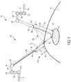
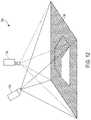
- FIG. 1is a schematic of a surgical visualization system including an imaging device and a surgical device, the surgical visualization system configured to identify a critical structure below a tissue surface, according to at least one aspect of the present disclosure.
- FIG. 2is a schematic of a control system for a surgical visualization system, according to at least one aspect of the present disclosure.
- FIG. 2Aillustrates a control circuit configured to control aspects of a surgical visualization system, according to at least one aspect of the present disclosure.
- FIG. 2Billustrates a combinational logic circuit configured to control aspects of a surgical visualization system, according to at least one aspect of the present disclosure.
- FIG. 2Cillustrates a sequential logic circuit configured to control aspects of a surgical visualization system, according to at least one aspect of the present disclosure.
- FIG. 3is a schematic depicting triangularization between the surgical device, the imaging device, and the critical structure of FIG. 1 to determine a depth d A of the critical structure below the tissue surface, according to at least one aspect of the present disclosure.
- FIG. 4is a schematic of a surgical visualization system configured to identify a critical structure below a tissue surface, wherein the surgical visualization system includes a pulsed light source for determining a depth d A of the critical structure below the tissue surface, according to at least one aspect of the present disclosure.
- FIG. 5is a schematic of a surgical visualization system including an imaging device and a surgical device, the surgical visualization system configured to identify a critical structure below a tissue surface, according to at least one aspect of the present disclosure.
- FIG. 6is a schematic of a surgical visualization system including a three-dimensional camera, wherein the surgical visualization system is configured to identify a critical structure that is embedded within tissue, according to at least one aspect of the present disclosure.
- FIGS. 7A and 7Bare views of the critical structure taken by the three-dimensional camera of FIG. 6 , in which FIG. 7A is a view from a left-side lens of the three-dimensional camera and FIG. 7B is a view from a right-side lens of the three-dimensional camera, according to at least one aspect of the present disclosure.
- FIG. 8is a schematic of the surgical visualization system of FIG. 6 , in which a camera-to-critical structure distance d w from the three-dimensional camera to the critical structure can be determined, according to at least one aspect of the present disclosure.
- FIG. 9is a schematic of a surgical visualization system utilizing two cameras to determine the position of an embedded critical structure, according to at least one aspect of the present disclosure.
- FIG. 10Ais a schematic of a surgical visualization system utilizing a camera that is moved axially between a plurality of known positions to determine a position of an embedded critical structure, according to at least one aspect of the present disclosure.
- FIG. 10Bis a schematic of the surgical visualization system of FIG. 10A , in which the camera is moved axially and rotationally between a plurality of known positions to determine a position of the embedded critical structure, according to at least one aspect of the present disclosure.
- FIG. 11is a schematic of a control system for a surgical visualization system, according to at least one aspect of the present disclosure.
- FIG. 12is a schematic of a structured light source for a surgical visualization system, according to at least one aspect of the present disclosure.
- FIG. 13is a schematic of a hyperspectral visualization system for imaging terrestrial features or objects, according to at least one aspect of the present disclosure.
- FIG. 14is a graphical representation of hyperspectral signatures for various terrestrial features or objects, according to at least one aspect of the present disclosure.
- FIGS. 15A-15Cshow an example of a hyperspectral visualization system for imaging a fried egg
- FIG. 15Ais a photograph of the fried egg
- FIG. 15Bis a graphical representation of hyperspectral signatures for an egg yolk portion and an egg white portion of the fried egg
- FIG. 15Cis a hyperspectral image (shown in black-and-white) of the fried egg, in which an augmented image differentiates between the egg yolk portion and the egg white portion based on hyperspectral signature data, according to at least one aspect of the present disclosure.
- FIGS. 16-18depict illustrative hyperspectral identifying signatures to differentiate anatomy from obscurants, wherein FIG. 16 is a graphical representation of a ureter signature versus obscurants, FIG. 17 is a graphical representation of an artery signature versus obscurants, and FIG. 18 is a graphical representation of a nerve signature versus obscurants, according to at least one aspect of the present disclosure.
- FIG. 19is a schematic of a near infrared (NIR) time-of-flight measurement system configured to sense distance to a critical anatomical structure, the time-of-flight measurement system including a transmitter (emitter) and a receiver (sensor) positioned on a common device, according to at least one aspect of the present disclosure.
- NIRnear infrared
- FIG. 20is a schematic of an emitted wave, a received wave, and a delay between the emitted wave and the received wave of the NIR time-of-flight measurement system of FIG. 19 , according to at least one aspect of the present disclosure.
- FIG. 21illustrates a NIR time-of-flight measurement system configured to sense a distance to different structures, the time-of-flight measurement system including a transmitter (emitter) and a receiver (sensor) on separate devices, according to one aspect of the present disclosure.
- FIG. 22is a partial perspective view of a robotically-assisted suturing system comprising a grasper, a suturing needle, and a surgical visualization assembly, according to at least one aspect of the present disclosure.
- FIG. 23is a perspective view a video monitor displaying information gathered by a waveform sensor in a surgical site, according to at least one aspect of the present disclosure.
- FIG. 24illustrates a first phase of a robotically assisted suture motion using a grasper and a suture needle where a surgeon manually touches the suture needle to the surface of tissue with the grasper.
- FIG. 25illustrates a second phase of the robotically assisted suture motion of FIG. 24 where a surgeon initiates an automatic, robotically-assisted portion of the suture motion where the grasper is actuated through a suturing stroke by the robotic system automatically.
- FIG. 26illustrates a third phase of the robotically assisted suture motion of FIG. 24 where the grasper grabs a tip of the suture needle.
- FIG. 27is a flowchart depicting an algorithm for a surgical visualization feedback system used to determine the relative position of a suturing needle and an embedded tissue structure.
- FIG. 28is a flowchart depicting an algorithm for a surgical visualization feedback system for use with a surgical suturing system.
- FIG. 29is a flowchart depicting an algorithm for a surgical visualization feedback system for use with a robotically-assisted surgical suturing system.
- FIG. 30is a flowchart of a process utilizing a robotically assisted suturing system, according to at least one aspect of the present disclosure.
- FIG. 31is a flowchart of a process utilizing a robotically assisted suturing system, according to at least one aspect of the present disclosure.
- the present disclosureis directed to a surgical visualization platform that leverages “digital surgery” to obtain additional information about a patient's anatomy and/or a surgical procedure.
- the surgical visualization platformis further configured to convey data and/or information to one or more clinicians in a helpful manner.
- various aspects of the present disclosureprovide improved visualization of the patient's anatomy and/or the surgical procedure.
- Digital surgerycan embrace robotic systems, advanced imaging, advanced instrumentation, artificial intelligence, machine learning, data analytics for performance tracking and benchmarking, connectivity both inside and outside of the operating room (OR), and more.
- various surgical visualization platforms described hereincan be used in combination with a robotic surgical system, surgical visualization platforms are not limited to use with a robotic surgical system.
- advanced surgical visualizationcan occur without robotics and/or with limited and/or optional robotic assistance.
- digital surgerycan occur without robotics and/or with limited and/or optional robotic assistance.
- a surgical system that incorporates a surgical visualization platformmay enable smart dissection in order to identify and avoid critical structures.
- Critical structuresinclude anatomical structures such as a ureter, an artery such as a superior mesenteric artery, a vein such as a portal vein, a nerve such as a phrenic nerve, and/or a tumor, among other anatomical structures.
- a critical structurecan be a foreign structure in the anatomical field, such as a surgical device, surgical fastener, clip, tack, bougie, band, and/or plate, for example.
- Critical structurescan be determined on a patient-by-patient and/or a procedure-by-procedure basis. Example critical structures are further described herein. Smart dissection technology may provide improved intraoperative guidance for dissection and/or can enable smarter decisions with critical anatomy detection and avoidance technology, for example.
- a surgical system incorporating a surgical visualization platformmay also enable smart anastomosis technologies that provide more consistent anastomoses at optimal location(s) with improved workflow.
- Cancer localization technologiesmay also be improved with the various surgical visualization platforms and procedures described herein. For example, cancer localization technologies can identify and track a cancer location, orientation, and its margins. In certain instances, the cancer localizations technologies may compensate for movement of a tool, a patient, and/or the patient's anatomy during a surgical procedure in order to provide guidance back to the point of interest for the clinician.
- tissue characterization technologiesmay characterize tissue type and health without the need for physical haptics, especially when dissecting and/or placing stapling devices within the tissue. Certain tissue characterization technologies described herein may be utilized without ionizing radiation and/or contrast agents.
- a surgical visualization platformmay preoperatively locate, map, and ideally diagnose the lymph system and/or lymph nodes involved in cancerous diagnosis and staging, for example.
- the information available to the clinician via the “naked eye” and/or an imaging systemmay provide an incomplete view of the surgical site.
- certain structuressuch as structures embedded or buried within an organ, can be at least partially concealed or hidden from view.
- certain dimensions and/or relative distancescan be difficult to ascertain with existing sensor systems and/or difficult for the “naked eye” to perceive.
- certain structurescan move preoperatively (e.g. before a surgical procedure but after a preoperative scan) and/or intraoperatively. In such instances, the clinician can be unable to accurately determine the location of a critical structure intraoperatively.
- a clinician's decision-making processcan be inhibited. For example, a clinician may avoid certain areas in order to avoid inadvertent dissection of a critical structure; however, the avoided area may be unnecessarily large and/or at least partially misplaced. Due to uncertainty and/or overly/excessive exercises in caution, the clinician may not access certain desired regions. For example, excess caution may cause a clinician to leave a portion of a tumor and/or other undesirable tissue in an effort to avoid a critical structure even if the critical structure is not in the particular area and/or would not be negatively impacted by the clinician working in that particular area. In certain instances, surgical results can be improved with increased knowledge and/or certainty, which can allow a surgeon to be more accurate and, in certain instances, less conservative/more aggressive with respect to particular anatomical areas.
- the present disclosureprovides a surgical visualization system for intraoperative identification and avoidance of critical structures.
- the present disclosureprovides a surgical visualization system that enables enhanced intraoperative decision making and improved surgical outcomes.
- the disclosed surgical visualization systemprovides advanced visualization capabilities beyond what a clinician sees with the “naked eye” and/or beyond what an imaging system can recognize and/or convey to the clinician.
- the various surgical visualization systemscan augment and enhance what a clinician is able to know prior to tissue treatment (e.g. dissection) and, thus, may improve outcomes in various instances.
- a visualization systemcan include a first light emitter configured to emit a plurality of spectral waves, a second light emitter configured to emit a light pattern, and one or more receivers, or sensors, configured to detect visible light, molecular responses to the spectral waves (spectral imaging), and/or the light pattern.
- the surgical visualization systemcan also include an imaging system and a control circuit in signal communication with the receiver(s) and the imaging system. Based on output from the receiver(s), the control circuit can determine a geometric surface map, i.e. three-dimensional surface topography, of the visible surfaces at the surgical site and one or more distances with respect to the surgical site. In certain instances, the control circuit can determine one more distances to an at least partially concealed structure.
- the imaging systemcan convey the geometric surface map and the one or more distances to a clinician.
- an augmented view of the surgical site provided to the cliniciancan provide a representation of the concealed structure within the relevant context of the surgical site.
- the imaging systemcan virtually augment the concealed structure on the geometric surface map of the concealing and/or obstructing tissue similar to a line drawn on the ground to indicate a utility line below the surface.
- the imaging systemcan convey the proximity of one or more surgical tools to the visible and obstructing tissue and/or to the at least partially concealed structure and/or the depth of the concealed structure below the visible surface of the obstructing tissue.
- the visualization systemcan determine a distance with respect to the augmented line on the surface of the visible tissue and convey the distance to the imaging system.
- a surgical visualization systemfor intraoperative identification and avoidance of critical structures.
- a surgical visualization systemcan provide valuable information to a clinician during a surgical procedure.
- the cliniciancan confidently maintain momentum throughout the surgical procedure knowing that the surgical visualization system is tracking a critical structure such as a ureter, specific nerves, and/or critical blood vessels, for example, which may be approached during dissection, for example.
- the surgical visualization systemcan provide an indication to the clinician in sufficient time for the clinician to pause and/or slow down the surgical procedure and evaluate the proximity to the critical structure to prevent inadvertent damage thereto.
- the surgical visualization systemcan provide an ideal, optimized, and/or customizable amount of information to the clinician to allow the clinician to move confidently and/or quickly through tissue while avoiding inadvertent damage to healthy tissue and/or critical structure(s) and, thus, to minimize the risk of harm resulting from the surgical procedure.
- FIG. 1is a schematic of a surgical visualization system 100 according to at least one aspect of the present disclosure.
- the surgical visualization system 100can create a visual representation of a critical structure 101 within an anatomical field.
- the surgical visualization system 100can be used for clinical analysis and/or medical intervention, for example.
- the surgical visualization system 100can be used intraoperatively to provide real-time, or near real-time, information to the clinician regarding proximity data, dimensions, and/or distances during a surgical procedure.
- the surgical visualization system 100is configured for intraoperative identification of critical structure(s) and/or to facilitate the avoidance of the critical structure(s) 101 by a surgical device.
- a cliniciancan avoid maneuvering a surgical device around the critical structure 101 and/or a region in a predefined proximity of the critical structure 101 during a surgical procedure.
- the cliniciancan avoid dissection of and/or near a vein, artery, nerve, and/or vessel, for example, identified as the critical structure 101 , for example.
- the critical structure 101can be determined on a patient-by-patient and/or a procedure-by-procedure basis.
- the surgical visualization system 100incorporates tissue identification and geometric surface mapping in combination with a distance sensor system 104 . In combination, these features of the surgical visualization system 100 can determine a position of a critical structure 101 within the anatomical field and/or the proximity of a surgical device 102 to the surface 105 of the visible tissue and/or to the critical structure 101 .
- the surgical visualization system 100includes an imaging system that includes an imaging device 120 , such as a camera, for example, configured to provide real-time views of the surgical site.
- the imaging device 120is a spectral camera (e.g.
- the surgical visualization system 100includes a plurality of subsystems—an imaging subsystem, a surface mapping subsystem, a tissue identification subsystem, and/or a distance determining subsystem. These subsystems can cooperate to intraoperatively provide advanced data synthesis and integrated information to the clinician(s).
- the imaging devicecan include a camera or imaging sensor that is configured to detect visible light, spectral light waves (visible or invisible), and a structured light pattern (visible or invisible), for example.
- the imaging systemcan include an imaging device such as an endoscope, for example. Additionally or alternatively, the imaging system can include an imaging device such as an arthroscope, angioscope, bronchoscope, choledochoscope, colonoscope, cytoscope, duodenoscope, enteroscope, esophagogastro-duodenoscope (gastroscope), laryngoscope, nasopharyngo-neproscope, sigmoidoscope, thoracoscope, ureteroscope, or exoscope, for example. In other instances, such as in open surgery applications, the imaging system may not include a scope.
- the tissue identification subsystemcan be achieved with a spectral imaging system.
- the spectral imaging systemcan rely on hyperspectral imaging, multispectral imaging, or selective spectral imaging, for example.
- Hyperspectral imaging of tissueis further described in U.S. Pat. No. 9,274,047, titled SYSTEM AND METHOD FOR GROSS ANATOMIC PATHOLOGY USING HYPERSPECTRAL IMAGING, issued Mar. 1, 2016, which is incorporated by reference herein in its entirety.
- the surface mapping subsystemcan be achieved with a light pattern system, as further described herein.
- a light patternor structured light
- Known surface mapping techniquescan be utilized in the surgical visualization systems described herein.
- Structured lightis the process of projecting a known pattern (often a grid or horizontal bars) on to a surface.
- U.S. Patent Application Publication No. 2017/0055819, titled SET COMPRISING A SURGICAL INSTRUMENT, published Mar. 2, 2017, and U.S. Patent Application Publication No. 2017/0251900, titled DEPICTION SYSTEM, published Sep. 7, 2017,disclose a surgical system comprising a light source and a projector for projecting a light pattern.
- U.S. Patent Application Publication No. 2017/0055819, titled SET COMPRISING A SURGICAL INSTRUMENT, published Mar. 2, 2017, and U.S. Patent Application Publication No. 2017/0251900, titled DEPICTION SYSTEM, published Sep. 7, 2017,are incorporated by reference herein in their respective entireties.
- the distance determining systemcan be incorporated into the surface mapping system.
- structured lightcan be utilized to generate a three-dimensional virtual model of the visible surface and determine various distances with respect to the visible surface.
- the distance determining systemcan rely on time-of-flight measurements to determine one or more distances to the identified tissue (or other structures) at the surgical site.
- FIG. 2is a schematic diagram of a control system 133 , which can be utilized with the surgical visualization system 100 .
- the control system 133includes a control circuit 132 in signal communication with a memory 134 .
- the memory 134stores instructions executable by the control circuit 132 to determine and/or recognize critical structures (e.g. the critical structure 101 in FIG. 1 ), determine and/or compute one or more distances and/or three-dimensional digital representations, and to communicate certain information to one or more clinicians.
- the memory 134stores surface mapping logic 136 , imaging logic 138 , tissue identification logic 140 , or distance determining logic 141 or any combinations of the logic 136 , 138 , 140 , and 141 .
- the control system 133also includes an imaging system 142 having one or more cameras 144 (like the imaging device 120 in FIG. 1 ), one or more displays 146 , or one or more controls 148 or any combinations of these elements.
- the camera 144can include one or more image sensors 135 to receive signals from various light sources emitting light at various visible and invisible spectra (e.g. visible light, spectral imagers, three-dimensional lens, among others).
- the display 146can include one or more screens or monitors for depicting real, virtual, and/or virtually-augmented images and/or information to one or more clinicians.
- the heart of the camera 144is the image sensor 135 .
- image sensors 135are solid-state electronic devices containing up to millions of discrete photodetector sites called pixels.
- the image sensor 135 technologyfalls into one of two categories: Charge-Coupled Device (CCD) and Complementary Metal Oxide Semiconductor (CMOS) imagers and more recently, short-wave infrared (SWIR) is an emerging technology in imaging.
- CCDCharge-Coupled Device
- CMOSComplementary Metal Oxide Semiconductor
- SWIRshort-wave infrared
- Another type of image sensor 135employs a hybrid CCD/CMOS architecture (sold under the name “sCMOS”) and consists of CMOS readout integrated circuits (ROICs) that are bump bonded to a CCD imaging substrate.
- sCMOShybrid CCD/CMOS architecture
- ROICsCMOS readout integrated circuits
- CCD and CMOS image sensors 135are sensitive to wavelengths from approximately 350-1050 nm, although the range is usually given from 400-1000 nm.
- CMOS sensorsare, in general, more sensitive to IR wavelengths than CCD sensors.
- Solid state image sensors 135are based on the photoelectric effect and, as a result, cannot distinguish between colors. Accordingly, there are two types of color CCD cameras: single chip and three-chip.
- Single chip color CCD camerasoffer a common, low-cost imaging solution and use a mosaic (e.g. Bayer) optical filter to separate incoming light into a series of colors and employ an interpolation algorithm to resolve full color images. Each color is, then, directed to a different set of pixels.
- a mosaice.g. Bayer
- Three-chip color CCD camerasprovide higher resolution by employing a prism to direct each section of the incident spectrum to a different chip. More accurate color reproduction is possible, as each point in space of the object has separate RGB intensity values, rather than using an algorithm to determine the color. Three-chip cameras offer extremely high resolutions.
- the control system 133also includes a spectral light source 150 and a structured light source 152 .
- a single sourcecan be pulsed to emit wavelengths of light in the spectral light source 150 range and wavelengths of light in the structured light source 152 range.
- a single light sourcecan be pulsed to provide light in the invisible spectrum (e.g. infrared spectral light) and wavelengths of light on the visible spectrum.
- the spectral light source 150can be a hyperspectral light source, a multispectral light source, and/or a selective spectral light source, for example.
- the tissue identification logic 140can identify critical structure(s) via data from the spectral light source 150 received by the image sensor 135 portion of the camera 144 .
- the surface mapping logic 136can determine the surface contours of the visible tissue based on reflected structured light. With time-of-flight measurements, the distance determining logic 141 can determine one or more distance(s) to the visible tissue and/or the critical structure 101 . One or more outputs from the surface mapping logic 136 , the tissue identification logic 140 , and the distance determining logic 141 , can be provided to the imaging logic 138 , and combined, blended, and/or overlaid to be conveyed to a clinician via the display 146 of the imaging system 142 .
- FIGS. 2A-2Cthere is illustrated a control circuit 400 configured to control aspects of the surgical visualization system 100 , according to at least one aspect of this disclosure.
- the control circuit 400can be configured to implement various processes described herein.
- the control circuit 400may comprise a microcontroller comprising one or more processors 402 (e.g., microprocessor, microcontroller) coupled to at least one memory circuit 404 .
- the memory circuit 404stores machine-executable instructions that, when executed by the processor 402 , cause the processor 402 to execute machine instructions to implement various processes described herein.
- the processor 402may be any one of a number of single-core or multicore processors known in the art.
- the memory circuit 404may comprise volatile and non-volatile storage media.
- the processor 402may include an instruction processing unit 406 and an arithmetic unit 408 .
- the instruction processing unitmay be configured to receive instructions from the memory circuit 404 of this disclosure.
- FIG. 2Billustrates a combinational logic circuit 410 configured to control aspects of the surgical visualization system 100 , according to at least one aspect of this disclosure.
- the combinational logic circuit 410can be configured to implement various processes described herein.
- the combinational logic circuit 410may comprise a finite state machine comprising a combinational logic 412 configured to receive data associated with the surgical instrument or tool at an input 414 , process the data by the combinational logic 412 , and provide an output 416 .
- FIG. 2Cillustrates a sequential logic circuit 420 configured to control aspects of the surgical visualization system 100 , according to at least one aspect of this disclosure.
- the sequential logic circuit 420 or the combinational logic 422can be configured to implement various processes described herein.
- the sequential logic circuit 420may comprise a finite state machine.
- the sequential logic circuit 420may comprise a combinational logic 422 , at least one memory circuit 424 , and a clock 429 , for example.
- the at least one memory circuit 424can store a current state of the finite state machine.
- the sequential logic circuit 420may be synchronous or asynchronous.
- the combinational logic 422is configured to receive data associated with a surgical device or system from an input 426 , process the data by the combinational logic 422 , and provide an output 428 .
- the circuitmay comprise a combination of a processor (e.g., processor 402 in FIG. 2A ) and a finite state machine to implement various processes herein.
- the finite state machinemay comprise a combination of a combinational logic circuit (e.g., combinational logic circuit 410 , FIG. 2B ) and the sequential logic circuit 420 .
- the critical structure 101can be an anatomical structure of interest.
- the critical structure 101can be a ureter, an artery such as a superior mesenteric artery, a vein such as a portal vein, a nerve such as a phrenic nerve, and/or a tumor, among other anatomical structures.
- the critical structure 101can be a foreign structure in the anatomical field, such as a surgical device, surgical fastener, clip, tack, bougie, band, and/or plate, for example.
- Example critical structuresare further described herein and in the aforementioned contemporaneously-filed U.S. Patent Applications, including U.S. patent application Ser. No. 16/128,192, titled VISUALIZATION OF SURGICAL DEVICES, now U.S. Pat. No. 10,792,034, for example, which are incorporated by reference herein in their respective entireties.
- the critical structure 101may be embedded in tissue 103 . Stated differently, the critical structure 101 may be positioned below the surface 105 of the tissue 103 . In such instances, the tissue 103 conceals the critical structure 101 from the clinician's view. The critical structure 101 is also obscured from the view of the imaging device 120 by the tissue 103 .
- the tissue 103can be fat, connective tissue, adhesions, and/or organs, for example. In other instances, the critical structure 101 can be partially obscured from view.
- FIG. 1also depicts the surgical device 102 .
- the surgical device 102includes an end effector having opposing jaws extending from the distal end of the shaft of the surgical device 102 .
- the surgical device 102can be any suitable surgical device such as, for example, a dissector, a stapler, a grasper, a clip applier, and/or an energy device including mono-polar probes, bi-polar probes, ablation probes, and/or an ultrasonic end effector.
- the surgical device 102can include another imaging or diagnostic modality, such as an ultrasound device, for example.
- the surgical visualization system 100can be configured to achieve identification of one or more critical structures 101 and the proximity of the surgical device 102 to the critical structure(s) 101 .
- the imaging device 120 of the surgical visualization system 100is configured to detect light at various wavelengths, such as, for example, visible light, spectral light waves (visible or invisible), and a structured light pattern (visible or invisible).
- the imaging device 120may include a plurality of lenses, sensors, and/or receivers for detecting the different signals.
- the imaging device 120can be a hyperspectral, multispectral, or selective spectral camera, as further described herein.
- the imaging device 120can also include a waveform sensor 122 (such as a spectral image sensor, detector, and/or three-dimensional camera lens).
- the imaging device 120can include a right-side lens and a left-side lens used together to record two two-dimensional images at the same time and, thus, generate a three-dimensional image of the surgical site, render a three-dimensional image of the surgical site, and/or determine one or more distances at the surgical site.
- the imaging device 120can be configured to receive images indicative of the topography of the visible tissue and the identification and position of hidden critical structures, as further described herein.
- the field of view of the imaging device 120can overlap with a pattern of light (structured light) on the surface 105 of the tissue, as shown in FIG. 1 .
- the surgical visualization system 100may be incorporated into a robotic system 110 .
- the robotic system 110may include a first robotic arm 112 and a second robotic arm 114 .
- the robotic arms 112 , 114include rigid structural members 116 and joints 118 , which can include servomotor controls.
- the first robotic arm 112is configured to maneuver the surgical device 102
- the second robotic arm 114is configured to maneuver the imaging device 120 .
- a robotic control unitcan be configured to issue control motions to the robotic arms 112 , 114 , which can affect the surgical device 102 and the imaging device 120 , for example.
- the surgical visualization system 100also includes an emitter 106 , which is configured to emit a pattern of light, such as stripes, grid lines, and/or dots, to enable the determination of the topography or landscape of the surface 105 .
- projected light arrays 130can be used for three-dimensional scanning and registration on the surface 105 .
- the projected light arrays 130can be emitted from the emitter 106 located on the surgical device 102 and/or one of the robotic arms 112 , 114 and/or the imaging device 120 , for example.
- the projected light array 130is employed to determine the shape defined by the surface 105 of the tissue 103 and/or the motion of the surface 105 intraoperatively.
- the imaging device 120is configured to detect the projected light arrays 130 reflected from the surface 105 to determine the topography of the surface 105 and various distances with respect to the surface 105 .
- the imaging device 120also may include an optical waveform emitter 123 that is configured to emit electromagnetic radiation 124 (NIR photons) that can penetrate the surface 105 of the tissue 103 and reach the critical structure 101 .
- the imaging device 120 and the optical waveform emitter 123 thereoncan be positionable by the robotic arm 114 .
- a corresponding waveform sensor 122(an image sensor, spectrometer, or vibrational sensor, for example) on the imaging device 120 is configured to detect the effect of the electromagnetic radiation received by the waveform sensor 122 .
- the wavelengths of the electromagnetic radiation 124 emitted by the optical waveform emitter 123can be configured to enable the identification of the type of anatomical and/or physical structure, such as the critical structure 101 .
- the identification of the critical structure 101can be accomplished through spectral analysis, photo-acoustics, and/or ultrasound, for example.
- the wavelengths of the electromagnetic radiation 124may be variable.
- the waveform sensor 122 and optical waveform emitter 123may be inclusive of a multispectral imaging system and/or a selective spectral imaging system, for example. In other instances, the waveform sensor 122 and optical waveform emitter 123 may be inclusive of a photoacoustic imaging system, for example. In other instances, the optical waveform emitter 123 can be positioned on a separate surgical device from the imaging device 120 .
- the surgical visualization system 100also may include the distance sensor system 104 configured to determine one or more distances at the surgical site.
- the time-of-flight distance sensor system 104may be a time-of-flight distance sensor system that includes an emitter, such as the emitter 106 , and a receiver 108 , which can be positioned on the surgical device 102 .
- the time-of-flight emittercan be separate from the structured light emitter.
- the emitter 106 portion of the time-of-flight distance sensor system 104may include a very tiny laser source and the receiver 108 portion of the time-of-flight distance sensor system 104 may include a matching sensor.
- the time-of-flight distance sensor system 104can detect the “time of flight,” or how long the laser light emitted by the emitter 106 has taken to bounce back to the sensor portion of the receiver 108 .
- Use of a very narrow light source in the emitter 106enables the distance sensor system 104 to determining the distance to the surface 105 of the tissue 103 directly in front of the distance sensor system 104 .
- d eis the emitter-to-tissue distance from the emitter 106 to the surface 105 of the tissue 103
- d tis the device-to-tissue distance from the distal end of the surgical device 102 to the surface 105 of the tissue.
- the distance sensor system 104can be employed to determine the emitter-to-tissue distance d e .
- the device-to-tissue distance d tis obtainable from the known position of the emitter 106 on the shaft of the surgical device 102 relative to the distal end of the surgical device 102 . In other words, when the distance between the emitter 106 and the distal end of the surgical device 102 is known, the device-to-tissue distance d t can be determined from the emitter-to-tissue distance d e .
- the shaft of the surgical device 102can include one or more articulation joints, and can be articulatable with respect to the emitter 106 and the jaws.
- the articulation configurationcan include a multi-joint vertebrae-like structure, for example.
- a three-dimensional cameracan be utilized to triangulate one or more distances to the surface 105 .
- the receiver 108 for the time-of-flight distance sensor system 104can be mounted on a separate surgical device instead of the surgical device 102 .
- the receiver 108can be mounted on a cannula or trocar through which the surgical device 102 extends to reach the surgical site.
- the receiver 108 for the time-of-flight distance sensor system 104can be mounted on a separate robotically-controlled arm (e.g. the robotic arm 114 ), on a movable arm that is operated by another robot, and/or to an operating room (OR) table or fixture.
- the imaging device 120includes the time-of-flight receiver 108 to determine the distance from the emitter 106 to the surface 105 of the tissue 103 using a line between the emitter 106 on the surgical device 102 and the imaging device 120 .
- the distance d ecan be triangulated based on known positions of the emitter 106 (on the surgical device 102 ) and the receiver 108 (on the imaging device 120 ) of the time-of-flight distance sensor system 104 .
- the three-dimensional position of the receiver 108can be known and/or registered to the robot coordinate plane intraoperatively.
- the position of the emitter 106 of the time-of-flight distance sensor system 104can be controlled by the first robotic arm 112 and the position of the receiver 108 of the time-of-flight distance sensor system 104 can be controlled by the second robotic arm 114 .
- the surgical visualization system 100can be utilized apart from a robotic system. In such instances, the distance sensor system 104 can be independent of the robotic system.
- one or more of the robotic arms 112 , 114may be separate from a main robotic system used in the surgical procedure. At least one of the robotic arms 112 , 114 can be positioned and registered to a particular coordinate system without a servomotor control. For example, a closed-loop control system and/or a plurality of sensors for the robotic arms 110 can control and/or register the position of the robotic arm(s) 112 , 114 relative to the particular coordinate system. Similarly, the position of the surgical device 102 and the imaging device 120 can be registered relative to a particular coordinate system.
- d wis the camera-to-critical structure distance from the optical waveform emitter 123 located on the imaging device 120 to the surface of the critical structure 101
- d Ais the depth of the critical structure 101 below the surface 105 of the tissue 103 (i.e., the distance between the portion of the surface 105 closest to the surgical device 102 and the critical structure 101 ).
- the time-of-flight of the optical waveforms emitted from the optical waveform emitter 123 located on the imaging device 120can be configured to determine the camera-to-critical structure distance d w .
- the use of spectral imaging in combination with time-of-flight sensorsis further described herein.
- FIG. 1is the camera-to-critical structure distance from the optical waveform emitter 123 located on the imaging device 120 to the surface of the critical structure 101
- d Ais the depth of the critical structure 101 below the surface 105 of the tissue 103 (i.e., the distance between the portion of the surface 105 closest to the surgical device 102 and the critical structure 101
- the depth d A of the critical structure 101 relative to the surface 105 of the tissue 103can be determined by triangulating from the distance d w and known positions of the emitter 106 on the surgical device 102 and the optical waveform emitter 123 on the imaging device 120 (and, thus, the known distance d w therebetween) to determine the distance d y , which is the sum of the distances d e and d A .
- time-of-flight from the optical waveform emitter 123can be configured to determine the distance from the optical waveform emitter 123 to the surface 105 of the tissue 103 .
- a first waveform(or range of waveforms) can be utilized to determine the camera-to-critical structure distance d w and a second waveform (or range of waveforms) can be utilized to determine the distance to the surface 105 of the tissue 103 .
- the different waveformscan be utilized to determine the depth of the critical structure 101 below the surface 105 of the tissue 103 .
- the distance d Acan be determined from an ultrasound, a registered magnetic resonance imaging (MRI) or computerized tomography (CT) scan.
- the distance d Acan be determined with spectral imaging because the detection signal received by the imaging device can vary based on the type of material. For example, fat can decrease the detection signal in a first way, or a first amount, and collagen can decrease the detection signal in a different, second way, or a second amount.
- a surgical device 162includes the optical waveform emitter 123 and the waveform sensor 122 that is configured to detect the reflected waveforms.
- the optical waveform emitter 123can be configured to emit waveforms for determining the distances d t and d w from a common device, such as the surgical device 162 , as further described herein.
- various information regarding visible tissue, embedded critical structures, and surgical devicescan be determined by utilizing a combination approach that incorporates one or more time-of-flight distance sensors, spectral imaging, and/or structured light arrays in combination with an image sensor configured to detect the spectral wavelengths and the structured light arrays.
- the image sensorcan be configured to receive visible light and, thus, provide images of the surgical site to an imaging system.
- Logic or algorithmsare employed to discern the information received from the time-of-flight sensors, spectral wavelengths, structured light, and visible light and render three-dimensional images of the surface tissue and underlying anatomical structures.
- the imaging device 120can include multiple image sensors.
- the camera-to-critical structure distance d wcan also be detected in one or more alternative ways.
- a fluoroscopy visualization technologysuch as fluorescent indosciedine green (ICG), for example, can be utilized to illuminate a critical structure 201 , as shown in FIGS. 6-8 .
- a camera 220can include two optical waveforms sensors 222 , 224 , which take simultaneous left-side and right-side images of the critical structure 201 ( FIGS. 7A and 7B ). In such instances, the camera 220 can depict a glow of the critical structure 201 below the surface 205 of the tissue 203 , and the distance d w can be determined by the known distance between the sensors 222 and 224 .
- distancescan be determined more accurately by utilizing more than one camera or by moving a camera between multiple locations.
- one cameracan be controlled by a first robotic arm and a second camera by another robotic arm.
- one cameracan be a follower camera on a follower arm, for example.
- the follower arm, and camera thereon,can be programmed to track the other camera and to maintain a particular distance and/or lens angle, for example.
- the surgical visualization system 100may employ two separate waveform receivers (i.e. cameras/image sensors) to determine d w .
- two separate waveform receiversi.e. cameras/image sensors
- the actual locationcan be triangulated from two separate cameras 320 a , 320 b at known locations.
- a surgical visualization systemmay employ a dithering or moving camera 440 to determine the distance d w .
- the camera 440is robotically-controlled such that the three-dimensional coordinates of the camera 440 at the different positions are known.
- the camera 440can pivot at a cannula or patient interface.
- a critical structure 401 or the contents thereofe.g. a vessel or the contents of the vessel
- the actual locationcan be triangulated from the camera 440 moved rapidly between two or more known locations.
- the camera 440is moved axially along an axis A.
- the camera 440translates a distance d 1 closer to the critical structure 401 along the axis A to the location indicated as a location 440 ′, such as by moving in and out on a robotic arm.
- the distance to the critical structure 401can be calculated.
- a 4.28 mm axial translation(the distance d 1 ) can correspond to an angle ⁇ 1 of 6.28 degrees and an angle ⁇ 2 of 8.19 degrees.
- the camera 440can rotate or sweep along an arc between different positions. Referring now to FIG.
- the camera 440is moved axially along the axis A and is rotated an angle ⁇ 3 about the axis A.
- a pivot point 442 for rotation of the camera 440is positioned at the cannula/patient interface.
- the camera 440is translated and rotated to a location 440 ′′.
- the distance to the critical structure 401can be calculated.
- a distance d 2can be 9.01 mm, for example, and the angle ⁇ 3 can be 0.9 degrees, for example.
- FIG. 5depicts a surgical visualization system 500 , which is similar to the surgical visualization system 100 in many respects.
- the surgical visualization system 500can be a further exemplification of the surgical visualization system 100 .
- the surgical visualization system 500includes a surgical device 502 and an imaging device 520 .
- the imaging device 520includes a spectral light emitter 523 , which is configured to emit spectral light in a plurality of wavelengths to obtain a spectral image of hidden structures, for example.
- the imaging device 520can also include a three-dimensional camera and associated electronic processing circuits in various instances.
- the surgical visualization system 500is shown being utilized intraoperatively to identify and facilitate avoidance of certain critical structures, such as a ureter 501 a and vessels 501 b in an organ 503 (the uterus in this example), that are not visible on the surface.
- the surgical visualization system 500is configured to determine an emitter-to-tissue distance d e from an emitter 506 on the surgical device 502 to a surface 505 of the uterus 503 via structured light.
- the surgical visualization system 500is configured to extrapolate a device-to-tissue distance d t from the surgical device 502 to the surface 505 of the uterus 503 based on the emitter-to-tissue distance d e .
- the surgical visualization system 500is also configured to determine a tissue-to-ureter distance d A from the ureter 501 a to the surface 505 and a camera-to ureter distance d w from the imaging device 520 to the ureter 501 a . As described herein with respect to FIG.
- the surgical visualization system 500can determine the distance d w with spectral imaging and time-of-flight sensors, for example. In various instances, the surgical visualization system 500 can determine (e.g. triangulate) the tissue-to-ureter distance d A (or depth) based on other distances and/or the surface mapping logic described herein.
- the control system 600is a conversion system that integrates spectral signature tissue identification and structured light tissue positioning to identify critical structures, especially when those structures are obscured by other tissue, such as fat, connective tissue, blood, and/or other organs, for example. Such technology could also be useful for detecting tissue variability, such as differentiating tumors and/or non-healthy tissue from healthy tissue within an organ.
- the control system 600is configured for implementing a hyperspectral imaging and visualization system in which a molecular response is utilized to detect and identify anatomy in a surgical field of view.
- the control system 600includes a conversion logic circuit 648 to convert tissue data to surgeon usable information.
- the variable reflectance based on wavelengths with respect to obscuring materialcan be utilized to identify the critical structure in the anatomy.
- the control system 600combines the identified spectral signature and the structural light data in an image.
- the control system 600can be employed to create of three-dimensional data set for surgical use in a system with augmentation image overlays. Techniques can be employed both intraoperatively and preoperatively using additional visual information.
- the control system 600is configured to provide warnings to a clinician when in the proximity of one or more critical structures.
- Various algorithmscan be employed to guide robotic automation and semi-automated approaches based on the surgical procedure and proximity to the critical structure(s).
- a projected array of lightsis employed to determine tissue shape and motion intraoperatively.
- flash Lidarmay be utilized for surface mapping of the tissue.
- the control system 600is configured to detect the critical structure(s) and provide an image overlay of the critical structure and measure the distance to the surface of the visible tissue and the distance to the embedded/buried critical structure(s). In other instances, the control system 600 can measure the distance to the surface of the visible tissue or detect the critical structure(s) and provide an image overlay of the critical structure.
- the control system 600includes a spectral control circuit 602 .
- the spectral control circuit 602can be a field programmable gate array (FPGA) or another suitable circuit configuration as described herein in connection with FIGS. 2A-2C , for example.
- the spectral control circuit 602includes a processor 604 to receive video input signals from a video input processor 606 .
- the processor 604can be configured for hyperspectral processing and can utilize C/C++ code, for example.
- the video input processor 606receives video-in of control (metadata) data such as shutter time, wave length, and sensor analytics, for example.
- metadatavideo-in of control
- the processor 604is configured to process the video input signal from the video input processor 606 and provide a video output signal to a video output processor 608 , which includes a hyperspectral video-out of interface control (metadata) data, for example.
- the video output processor 608provides the video output signal to an image overlay controller 610 .
- the video input processor 606is coupled to a camera 612 at the patient side via a patient isolation circuit 614 .
- the camera 612includes a solid state image sensor 634 .
- the patient isolation circuitcan include a plurality of transformers so that the patient is isolated from other circuits in the system.
- the camera 612receives intraoperative images through optics 632 and the image sensor 634 .
- the image sensor 634can include a CMOS image sensor, for example, or may include any of the image sensor technologies discussed herein in connection with FIG. 2 , for example.
- the camera 612outputs images in 14 bit/pixel signals. It will be appreciated that higher or lower pixel resolutions may be employed without departing from the scope of the present disclosure.
- the isolated camera output signal 613is provided to a color RGB fusion circuit 616 , which employs a hardware register 618 and a Nios2 co-processor 620 to process the camera output signal 613 .
- a color RGB fusion output signalis provided to the video input processor 606 and a laser pulsing control circuit 622 .
- the laser pulsing control circuit 622controls a laser light engine 624 .
- the laser light engine 624outputs light in a plurality of wavelengths ( ⁇ 1 , ⁇ 2 , ⁇ 3 . . . ⁇ n ) including near infrared (NIR).
- the laser light engine 624can operate in a plurality of modes. In one aspect, the laser light engine 624 can operate in two modes, for example. In a first mode, e.g. a normal operating mode, the laser light engine 624 outputs an illuminating signal. In a second mode, e.g. an identification mode, the laser light engine 624 outputs RGBG and NIR light. In various instances, the laser light engine 624 can operate in a polarizing mode.
- Light output 626 from the laser light engine 624illuminates targeted anatomy in an intraoperative surgical site 627 .
- the laser pulsing control circuit 622also controls a laser pulse controller 628 for a laser pattern projector 630 that projects a laser light pattern 631 , such as a grid or pattern of lines and/or dots, at a predetermined wavelength ( ⁇ 2 ) on the operative tissue or organ at the surgical site 627 .
- the camera 612receives the patterned light as well as the reflected light output through the camera optics 632 .
- the image sensor 634converts the received light into a digital signal.
- the color RGB fusion circuit 616also outputs signals to the image overlay controller 610 and a video input module 636 for reading the laser light pattern 631 projected onto the targeted anatomy at the surgical site 627 by the laser pattern projector 630 .
- a processing module 638processes the laser light pattern 631 and outputs a first video output signal 640 representative of the distance to the visible tissue at the surgical site 627 .
- the datais provided to the image overlay controller 610 .
- the processing module 638also outputs a second video signal 642 representative of a three-dimensional rendered shape of the tissue or organ of the targeted anatomy at the surgical site.
- the first and second video output signals 640 , 642include data representative of the position of the critical structure on a three-dimensional surface model, which is provided to an integration module 643 .
- the integration module 643can determine the distance d A ( FIG. 1 ) to a buried critical structure (e.g. via triangularization algorithms 644 ), and the distance d A can be provided to the image overlay controller 610 via a video out processor 646 .
- the foregoing conversion logiccan encompass the conversion logic circuit 648 intermediate video monitors 652 and the camera 624 /laser pattern projector 630 positioned at the surgical site 627 .
- Preoperative data 650 from a CT or MRI scancan be employed to register or align certain three-dimensional deformable tissue in various instances.
- Such preoperative data 650can be provided to the integration module 643 and ultimately to the image overlay controller 610 so that such information can be overlaid with the views from the camera 612 and provided to the video monitors 652 .
- Registration of preoperative datais further described herein and in the aforementioned contemporaneously-filed U.S. Patent Applications, including U.S. patent application Ser. No. 16/128,195, titled INTEGRATION OF IMAGING DATA, now U.S. Patent Application Publication No. 2020/0015907, for example, which are incorporated by reference herein in their respective entireties.
- the video monitors 652can output the integrated/augmented views from the image overlay controller 610 .
- a cliniciancan select and/or toggle between different views on one or more monitors.
- the cliniciancan toggle between (A) a view in which a three-dimensional rendering of the visible tissue is depicted and (B) an augmented view in which one or more hidden critical structures are depicted over the three-dimensional rendering of the visible tissue.
- the cliniciancan toggle on distance measurements to one or more hidden critical structures and/or the surface of visible tissue, for example.
- control system 600 and/or various control circuits thereofcan be incorporated into various surgical visualization systems disclosed herein.
- FIG. 12illustrates a structured (or patterned) light system 700 , according to at least one aspect of the present disclosure.
- structured light in the form of stripes or linescan be projected from a light source and/or projector 706 onto the surface 705 of targeted anatomy to identify the shape and contours of the surface 705 .
- a camera 720which can be similar in various respects to the imaging device 120 ( FIG. 1 ), for example, can be configured to detect the projected pattern of light on the surface 705 . The way that the projected pattern deforms upon striking the surface 705 allows vision systems to calculate the depth and surface information of the targeted anatomy.
- invisible (or imperceptible) structured lightcan be utilized, in which the structured light is used without interfering with other computer vision tasks for which the projected pattern may be confusing.
- infrared light or extremely fast frame rates of visible light that alternate between two exact opposite patternscan be utilized to prevent interference. Structured light is further described at en.wikipedia.org/wiki/Structured_light
- the terrestrial hyperspectral imaging system 800is configured to image terrestrial features or objects, such as soil, water, and/or vegetation, for example.
- the terrestrial hyperspectral imaging system 700includes a space-borne hyperspectral sensor 822 on a spacecraft 820 to conduct hyperspectral imaging of a portion of the Earth's surface 805 .
- the spectral dimensionincludes several layers. Each pixel of the images contains a sampled spectrum that is used to identify the materials present in the pixel by their reflectance.
- the datacan be converted to graphical representations 850 , 852 , 854 of reflectance as a function of wavelength for soil, water, and vegetation, respectively, for example.
- Terrestrial hyperspectral imagingis further described at www.markelowitz.com/Hyperspectral.html.
- FIG. 14is a graphical representation 850 of hyperspectral signatures for various terrestrial features or objects, according to at least one aspect of the present disclosure. Percent reflectance is shown along the vertical axis and wavelength (nm) is shown along the horizontal axis. As shown, each object—pinewoods, grasslands, red sand pit, and silty water—has a unique hyperspectral signature that can be used to identify the object.
- the hyperspectral imaging concepts described in connection with FIGS. 13 and 14may be employed for different materials that have different wavelengths and bands of absorption, according to at least one aspect of the present disclosure.
- the following tableillustrates the wavelengths and bands of absorption for various materials.
- a first range of wavelengths between 400 nm and 700 nmrepresents the visible light spectrum.
- a second range of wavelengths between 700 nm and 1400 nmrepresents the near infrared (NIR) spectrum.
- a third range of wavelengths between 1400 nm and 3000 nmrepresents a shortwave infrared (SWIR) spectrum.
- a first band centered at 1250 nmrepresents iron absorption and leaf moisture content.
- a second band between 1500 nm and 1750 nmrepresents plastics, fiberglass, and petroleum.
- a third band between 200 nm and 2400 nmrepresents mineral ID.
- TABLE 1specifies wavelengths and bands of absorption for various materials.
- FIGS. 15A-15Cas a further illustration of hyperspectral imaging concepts, tests were conducted in which spectral imaging was applied to a fried egg 952 .
- a graphical representation 950 of spectral signatures for the fried egg 952are shown in FIG. 15B .
- the graphical representation 950shows absorption units versus wavelength (nm) for the egg yolk 954 and the egg white 956 of the fried egg 952 .
- FIG. 15Ca spectral image (in black-and-white) of the fried egg 952 is shown, in which the image is augmented to differentiate between the egg yolk portion and the egg white portion based on the hyperspectral signature data.
- hyperspectral imaging technologyas described herein for illustrative purposes with respect to terrestrial features and objects and a fried egg, can be employed to identify signatures in anatomical structures in order to differentiate a critical structure from obscurants.
- Hyperspectral imaging technologymay provide a visualization system that can provide a way to identify critical structures such as ureters and/or blood vessels, for example, especially when those structures are obscured by fat, connective tissue, blood, or other organs, for example.
- the use of the difference in reflectance of different wavelengths in the infrared (IR) spectrummay be employed to determine the presence of key structures versus obscurants.
- FIGS. 16-18illustrative hyperspectral signatures for a ureter, an artery, and nerve tissue with respect to obscurants such as fat, lung tissue, and blood, for example, are depicted.
- FIG. 16is a graphical representation 1050 of an illustrative ureter signature versus obscurants. The plots represent reflectance as a function of wavelength (nm) for wavelengths for fat, lung tissue, blood, and a ureter.
- FIG. 17is a graphical representation 1052 of an illustrative artery signature versus obscurants. The plots represent reflectance as a function of wavelength (nm) for fat, lung tissue, blood, and a vessel.
- FIG. 18is a graphical representation 1054 of an illustrative nerve signature versus obscurants. The plots represent reflectance as a function of wavelength (nm) for fat, lung tissue, blood, and a nerve.
- select wavelengths for spectral imagingcan be identified and utilized based on the anticipated critical structures and/or obscurants at a surgical site (i.e. “selective spectral” imaging). By utilizing selective spectral imaging, the amount of time required to obtain the spectral image can be minimized such that the information can be obtained in real-time, or near real-time, and utilized intraoperatively.
- the wavelengthscan be selected by a clinician or by a control circuit based on input by the clinician. In certain instances, the wavelengths can be selected based on machine learning and/or big data accessible to the control circuit via a cloud, for example.
- spectral imaging to tissuecan be utilized intraoperatively to measure the distance between a waveform emitter and a critical structure that is obscured by tissue.
- a time-of-flight sensor system 1104utilizing waveforms 1124 , 1125 is shown.
- the time-of-flight sensor system 1104can be incorporated into the surgical visualization system 100 ( FIG. 1 ) in certain instances.
- the time-of-flight sensor system 1104includes a waveform emitter 1106 and a waveform receiver 1108 on the same surgical device 1102 .
- the emitted wave 1124extends to the critical structure 1101 from the emitter 1106 and the received wave 1125 is reflected back to by the receiver 1108 from the critical structure 1101 .
- the surgical device 1102is positioned through a trocar 1110 that extends into a cavity 1107 in a patient.
- the waveforms 1124 , 1125are configured to penetrate obscuring tissue 1103 .
- the wavelengths of the waveforms 1124 , 1125can be in the NIR or SWIR spectrum of wavelengths.
- a spectral signale.g. hyperspectral, multispectral, or selective spectral
- a photoacoustic signalcan be emitted from the emitter 1106 and can penetrate the tissue 1103 in which the critical structure 1101 is concealed.
- the emitted waveform 1124can be reflected by the critical structure 1101 .
- the received waveform 1125can be delayed due to the distance d between the distal end of the surgical device 1102 and the critical structure 1101 .
- the waveforms 1124 , 1125can be selected to target the critical structure 1101 within the tissue 1103 based on the spectral signature of the critical structure 1101 , as further described herein.
- the emitter 1106is configured to provide a binary signal on and off, as shown in FIG. 20 , for example, which can be measured by the receiver 1108 .
- the time-of-flight sensor system 1104is configured to determine the distance d ( FIG. 19 ).
- a time-of-flight timing diagram 1130 for the emitter 1106 and the receiver 1108 of FIG. 19is shown in FIG. 20 .
- the delayis a function of the distance d and the distance d is given by:
- the time-of-flight of the waveforms 1124 , 1125corresponds to the distance din FIG. 19 .
- additional emitters/receivers and/or pulsing signals from the emitter 1106can be configured to emit a non-penetrating signal.
- the non-penetrating tissuecan be configured to determine the distance from the emitter to the surface 1105 of the obscuring tissue 1103 .
- d Athe depth of the critical structure 1101 ;
- d wthe distance from the emitter 1106 to the critical structure 1101 (din FIG. 19 );
- d tthe distance from the emitter 1106 (on the distal end of the surgical device 1102 ) to the surface 1105 of the obscuring tissue 1103 .
- a time-of-flight sensor system 1204utilizing waves 1224 a , 1224 b , 1224 c , 1225 a , 1225 b , 1225 c is shown.
- the time-of-flight sensor system 1204can be incorporated into the surgical visualization system 100 ( FIG. 1 ) in certain instances.
- the time-of-flight sensor system 1204includes a waveform emitter 1206 and a waveform receiver 1208 .
- the waveform emitter 1206is positioned on a first surgical device 1202 a
- the waveform receiver 1208is positioned on a second surgical device 1202 b .
- the surgical devices 1202 a , 1202 bare positioned through their respective trocars 1210 a , 1210 b , respectively, which extend into a cavity 1207 in a patient.
- the emitted waves 1224 a , 1224 b , 1224 cextend toward a surgical site from the emitter 1206 and the received waves 1225 a , 1225 b , 1225 c are reflected back to the receiver 1208 from various structures and/or surfaces at the surgical site.
- the different emitted waves 1224 a , 1224 b , 1224 care configured to target different types of material at the surgical site.
- the wave 1224 atargets the obscuring tissue 1203
- the wave 1224 btargets a first critical structure 1201 a (e.g. a vessel)
- the wave 1224 ctargets a second critical structure 1201 b (e.g. a cancerous tumor).
- the wavelengths of the waves 1224 a , 1224 b , 1224 ccan be in the visible light, NIR, or SWIR spectrum of wavelengths.
- visible lightcan be reflected off a surface 1205 of the tissue 1203 and NIR and/or SWIR waveforms can be configured to penetrate the surface 1205 of the tissue 1203 .
- a spectral signale.g. hyperspectral, multispectral, or selective spectral
- a photoacoustic signalcan be emitted from the emitter 1206 .
- the waves 1224 b , 1224 ccan be selected to target the critical structures 1201 a , 1201 b within the tissue 1203 based on the spectral signature of the critical structure 1201 a , 1201 b , as further described herein.
- Photoacoustic imagingis further described herein and in the aforementioned contemporaneously-filed U.S. Patent Applications, which are incorporated by reference herein in their respective entireties.
- the emitted waves 1224 a , 1224 b , 1224 ccan be reflected off the targeted material (i.e. the surface 1205 , the first critical structure 1201 a , and the second structure 1201 b , respectively).
- the received waveforms 1225 a , 1225 b , 1225 ccan be delayed due to the distances d 1a , d 2a , d 3a , d 1b , d 2b , d 2c indicated in FIG. 21 .
- the various distances d 1a , d 2a , d 3a , d 1b , d 2b , d 2ccan be calculated from the known position of the emitter 1206 and the receiver 1208 .
- the positionscan be known when the surgical devices 1202 a , 1202 b are robotically-controlled.
- the distance to the obscured critical structures 1201 a , 1201 bcan be triangulated using penetrating wavelengths. Because the speed of light is constant for any wavelength of visible or invisible light, the time-of-flight sensor system 1204 can determine the various distances.
- the receiver 1208can be rotated such that the center of mass of the target structure in the resulting images remains constant, i.e., in a plane perpendicular to the axis of a select target structures 1203 , 1201 a , or 1201 b .
- Such an orientationcan quickly communicate one or more relevant distances and/or perspectives with respect to the critical structure.
- the surgical siteis displayed from a viewpoint in which the critical structure 1201 a is perpendicular to the viewing plane (i.e. the vessel is oriented in/out of the page).
- such an orientationcan be default setting; however, the view can be rotated or otherwise adjusted by a clinician.
- the cliniciancan toggle between different surfaces and/or target structures that define the viewpoint of the surgical site provided by the imaging system.
- the receiver 1208can be mounted on a trocar or cannula, such as the trocar 1210 b , for example, through which the surgical device 1202 b is positioned. In other instances, the receiver 1208 can be mounted on a separate robotic arm for which the three-dimensional position is known. In various instances, the receiver 1208 can be mounted on a movable arm that is separate from the robot that controls the surgical device 1202 a or can be mounted to an operating room (OR) table that is intraoperatively registerable to the robot coordinate plane. In such instances, the position of the emitter 1206 and the receiver 1208 can be registerable to the same coordinate plane such that the distances can be triangulated from outputs from the time-of-flight sensor system 1204 .
- TOF-NIRStime-of-flight sensor systems and near-infrared spectroscopy
- time-of-flight spectral waveformsare configured to determine the depth of the critical structure and/or the proximity of a surgical device to the critical structure.
- the various surgical visualization systems disclosed hereininclude surface mapping logic that is configured to create three-dimensional rendering of the surface of the visible tissue. In such instances, even when the visible tissue obstructs a critical structure, the clinician can be aware of the proximity (or lack thereof) of a surgical device to the critical structure. In one instances, the topography of the surgical site is provided on a monitor by the surface mapping logic. If the critical structure is close to the surface of the tissue, spectral imaging can convey the position of the critical structure to the clinician. For example, spectral imaging may detect structures within 5 or 10 mm of the surface.
- spectral imagingmay detect structures 10 or 20 mm below the surface of the tissue. Based on the known limits of the spectral imaging system, the system is configured to convey that a critical structure is out-of-range if it is simply not detected by the spectral imaging system. Therefore, the clinician can continue to move the surgical device and/or manipulate the tissue. When the critical structure moves into range of the spectral imaging system, the system can identify the structure and, thus, communicate that the structure is within range. In such instances, an alert can be provided when a structure is initially identified and/or moved further within a predefined proximity zone. In such instances, even non-identification of a critical structure by a spectral imaging system with known bounds/ranges can provide proximity information (i.e. the lack of proximity) to the clinician.
- proximity informationi.e. the lack of proximity
- Various surgical visualization systems disclosed hereincan be configured to identify intraoperatively the presence of and/or proximity to critical structure(s) and to alert a clinician prior to damaging the critical structure(s) by inadvertent dissection and/or transection.
- the surgical visualization systemsare configured to identify one or more of the following critical structures: ureters, bowel, rectum, nerves (including the phrenic nerve, recurrent laryngeal nerve [RLN], promontory facial nerve, vagus nerve, and branches thereof), vessels (including the pulmonary and lobar arteries and veins, inferior mesenteric artery [IMA] and branches thereof, superior rectal artery, sigmoidal arteries, and left colic artery), superior mesenteric artery (SMA) and branches thereof (including middle colic artery, right colic artery, ilecolic artery), hepatic artery and branches thereof, portal vein and branches thereof, splenic artery/vein and branches thereof, external and internal (hypogastric) ilea
- various aspects of the present disclosureprovide intraoperative critical structure identification (e.g., identification of ureters, nerves, and/or vessels) and instrument proximity monitoring.
- various surgical visualization systems disclosed hereincan include spectral imaging and surgical instrument tracking, which enable the visualization of critical structures below the surface of the tissue, such as 1.0-1.5 cm below the surface of the tissue, for example.
- the surgical visualization systemcan identify structures less than 1.0 cm or more the 1.5 cm below the surface of the tissue. For example, even a surgical visualization system that can identify structures only within 0.2 mm of the surface, for example, can be valuable if the structure cannot otherwise be seen due to the depth.
- the surgical visualization systemcan augment the clinician's view with a virtual depiction of the critical structure as a visible white-light image overlay on the surface of visible tissue, for example.
- the surgical visualization systemcan provide real-time, three-dimensional spatial tracking of the distal tip of surgical instruments and can provide a proximity alert when the distal tip of a surgical instrument moves within a certain range of the critical structure, such as within 1.0 cm of the critical structure, for example.
- Various surgical visualization systems disclosed hereincan identify when dissection is too close to a critical structure. Dissection may be “too close” to a critical structure based on the temperature (i.e. too hot within a proximity of the critical structure that may risk damaging/heating/melting the critical structure) and/or based on tension (i.e. too much tension within a proximity of the critical structure that may risk damaging/tearing/pulling the critical structure).
- a surgical visualization systemcan facilitate dissection around vessels when skeletonizing the vessels prior to ligation, for example.
- a thermal imaging cameracan be utilized to read the heat at the surgical site and provide a warning to the clinician that is based on the detected heat and the distance from a tool to the structure.
- an alertcan be provided to the clinician at a first distance (such as 10 mm, for example), and if the temperature of the tool is less than or equal to the predefined threshold, the alert can be provided to the clinician at a second distance (such as 5 mm, for example).
- the predefined thresholds and/or warning distancescan be default settings and/or programmable by the clinician.
- a proximity alertcan be linked to thermal measurements made by the tool itself, such as a thermocouple that measures the heat in a distal jaw of a monopolar or bipolar dissector or vessel sealer, for example.
- Various surgical visualization systems disclosed hereincan provide adequate sensitivity with respect to a critical structure and specificity to enable a clinician to proceed with confidence in a quick but safe dissection based on the standard of care and/or device safety data.
- the systemcan function intraoperatively and in real-time during a surgical procedure with minimal ionizing radiation risk to a patient or a clinician and, in various instances, no risk of ionizing radiation risk to the patient or the clinician.
- the patient and clinician(s)may be exposed to ionizing radiation via an X-ray beam, for example, that is utilized to view the anatomical structures in real-time.
- Various surgical visualization system disclosed hereincan be configured to detect and identify one or more desired types of critical structures in a forward path of a surgical device, such as when the path of the surgical device is robotically controlled, for example. Additionally or alternatively, the surgical visualization system can be configured to detect and identify one or more types of critical structures in a surrounding area of the surgical device and/or in multiple planes/dimensions, for example.
- various surgical visualization systems disclosed hereincan be easy to operate and/or interpret.
- various surgical visualization systemscan incorporate an “override” feature that allows the clinician to override a default setting and/or operation. For example, a clinician can selectively turn off alerts from the surgical visualization system and/or get closer to a critical structure than suggested by the surgical visualization system such as when the risk to the critical structure is less than risk of avoiding the area (e.g. when removing cancer around a critical structure the risk of leaving the cancerous tissue can be greater than the risk of damage to the critical structure).
- Various surgical visualization systems disclosed hereincan be incorporated into a surgical system and/or used during a surgical procedure with limited impact to the workflow. In other words, implementation of the surgical visualization system may not change the way the surgical procedure is implemented. Moreover, the surgical visualization system can be economical in comparison to the costs of an inadvertent transection. Data indicates the reduction in inadvertent damage to a critical structure can drive incremental reimbursement.
- Various surgical visualization systems disclosed hereincan operate in real-time, or near real-time, and far enough in advance to enable a clinician to anticipate critical structure(s). For example, a surgical visualization system can provide enough time to “slow down, evaluate, and avoid” in order to maximize efficiency of the surgical procedure.
- Various surgical visualization systems disclosed hereinmay not require a contrast agent, or dye, that is injected into tissue.
- spectral imagingis configured to visualize hidden structures intraoperatively without the use of a contrast agent or dye.
- the contrast agentcan be easier to inject into the proper layer(s) of tissue than other visualization systems.
- the time between injection of the contrast agent and visualization of the critical structurecan be less than two hours, for example.
- Various surgical visualization systems disclosed hereincan be linked with clinical data and/or device data.
- datacan provide boundaries for how close energy-enabled surgical devices (or other potentially damaging devices) should be from tissue that the surgeon does not want to damage.
- Any data modules that interface with the surgical visualization systems disclosed hereincan be provided integrally or separately from a robot to enable use with stand-alone surgical devices in open or laparoscopic procedures, for example.
- the surgical visualization systemscan be compatible with robotic surgical systems in various instances. For example, the visualization images/information can be displayed in a robotic console.
- Various surgical visualization systems disclosed hereinmay be employed in one or more of the following clinical applications.
- the following clinical applicationsare non-exhaustive and merely illustrative applications for one or more of the various surgical visualization systems disclosed herein.
- a surgical visualization systemcan be employed in a number of different types of procedures for different medical specialties, such as urology, gynecology, oncology, colorectal, thoracic, bariatric/gastric, and hepato-pancreato-biliary (HPB), for example.
- urological proceduressuch as a prostatectomy, for example, the ureter may be detected in fat or connective tissue and/or nerves may be detected in fat, for example.
- the uretermay be detected in fat and/or in connective tissue, for example.
- a vesselmay be detected in the lung or in connective tissue and/or a nerve may be detected in connective tissue (e.g., an esophagostomy).
- a vesselmay be detected in fat.
- a vesselmay be detected in fat (extrahepatic), in connective tissue (extrahepatic), and the bile duct may be detected in parenchyma (liver or pancreas) tissue.
- a clinicianmay want to remove an endometrial myoma. From a preoperative magnetic resonance imaging (MRI) scan, the clinician may know that the endometrial myoma is located on the surface of the bowel. Therefore, the clinician may want to know, intraoperatively, what tissue constitute a portion of the bowel and what tissue constitutes a portion of the rectum.
- a surgical visualization systemcan indicate the different types of tissue (bowel versus rectum) and convey that information to a clinician via an imaging system.
- the imaging systemcan determine and communicate the proximity of a surgical device to the select tissue. In such instances, the surgical visualization system can provide increased procedural efficiency without critical complications.
- a clinicianmay stay away from certain anatomic regions to avoid getting too close to critical structures and, thus, the clinician may not remove all of the endometriosis, for example.
- a surgical visualization systemcan enable the gynecologist to mitigate the risk of getting too close to the critical structure such that the gynecologist can get close enough with the surgical device to remove all the endometriosis, which can improve the patient outcomes (democratizing surgery).
- Such a systemcan enable the surgeon to “keep moving” during the surgical procedure instead of repeatedly stopping and restarting in order to identify areas to avoid, especially during the application of therapeutic energy such as ultrasonic or electrosurgical energy, for example.
- therapeutic energysuch as ultrasonic or electrosurgical energy
- a clinicianmay risk dissection of a vessel at a location that is too proximal and, thus, which can affect blood supply to a lobe other than the target lobe.
- anatomic differences from patient to patientmay lead to dissection of a vessel (e.g. a branch) that affects a different lobe based on the particular patient.
- a surgical visualization systemcan enable the identification of the correct vessel at the desired location, which enables the clinician to dissect with appropriate anatomic certainty. For example, the system can confirm that the correct vessel is in the correct place and then the clinician can safely divide the vessel.
- a clinicianmay make multiple dissections before dissecting at the best location due to uncertainty about the anatomy of the vessel.
- a surgical visualization systemcan minimize the number of dissections by indicating the correct vessel and the best location for dissection.
- Ureters and cardinal ligamentsare dense and provide unique challenges during dissection. In such instances, it can be especially desirable to minimize the number of dissections.
- a cliniciane.g. a surgical oncologist
- a surgical visualization systemcan determine and/or convey such information to the clinician intraoperatively to enhance intraoperative decision making and improve surgical outcomes.
- the surgical visualization systemcan be compatible with minimally invasive surgery (MIS), open surgery, and/or robotic approaches using either an endoscope or exoscope, for example.
- MISminimally invasive surgery
- a clinicianmay want to turn off one or more alerts regarding the proximity of a surgical tool to one or more critical structure to avoid being overly conservative during a surgical procedure.
- the clinicianmay want to receive certain types of alerts, such as haptic feedback (e.g. vibrations/buzzing) to indicate proximity and/or or “no fly zones” to stay sufficiently far away from one or more critical structures.
- haptic feedbacke.g. vibrations/buzzing
- a surgical visualization systemcan provide flexibility based on the experience of the clinician and/or desired aggressiveness of the procedure, for example. In such instances, the system provides a balance between “knowing too much” and “knowing enough” to anticipate and avoid critical structures.
- the surgical visualization systemcan assist in planning the next step(s) during a surgical procedure.
- the systems, methods, devices, and control circuits discussed hereincan also benefit and be used in a surgical suturing environment. More specifically, the surgical visualization systems can benefit surgical suturing systems.
- a clinician suturing tissue manually, robotically, and/or manually and roboticallycan utilize such surgical visualization systems in a surgical suturing environment to help prevent contacting, puncturing, and/or scraping, for example, of an embedded structure with a suturing needle.
- the surgical visualization systemscan be used to monitor the position of a needle in addition to the position of a critical structure.
- surgical suturing systems utilizing such surgical visualization systemscan monitor and/or track the relative position between a suturing needle and one or more embedded structures in real time, for example, and can alert a clinician and/or automatically adjust operation of a robot that may be assisting the suturing procedure, for example, if the needle gets too close to a embedded structure.
- Other surgical suturing systemsare capable of predicting the path of a needle based on an initial starting point and comparing that path to detected embedded structures. Such systems can also recommend a different starting point and/or alert a clinician that the predicted suturing path to be preformed robotically may interfere with an embedded structure, for example.
- a system and method for robotically assisted suturing with indication of needle proximity to a critical structureis provided.
- the system and methodare configured to prevent a suture needle from contacting a critical structure during robotic surgery.
- the system and methodprovide a technique for programing a suture needle driver, such as a grasper, for example, to perform repetitive portions of the suturing process.
- FIG. 22depicts a surgical suturing system 5700 .
- the surgical suturing system 5700comprises a grasper 5701 , a surgical visualization assembly 5702 including a sensor and an emitter, and a suturing assembly comprising a needle 5703 and suturing material 5705 attached thereto configured to suture tissue T.
- the grasper 5701is configured to actuate the needle 5703 through a complete suturing stroke by puncturing the surface of the tissue T with a tip 5704 of the needle 5703 , crossing the gap 5706 of the tissue T, and causing the tip 5704 of the needle 5703 to puncture back out through the surface of the tissue T.
- the grasper 5701may be a part of a robotic system, for example, and can be actuated manually through the robot by an operator and/or automatically through the robot by a control program. As discussed in greater detail below, a repetitive portion of a suturing motion may be automated such as the suturing stroke. Such a robotic system can be seen in FIG. 1 , for example.
- the grasper 5701may be actuated by a robotic arm of the robotic system 110 .
- the control circuits discussed herein in connection with the surgical suturing systemscan be configured to operate the robotic system directly. In other instances, the control circuits can be configured to send instructions to a control circuit of the robotic system itself.
- the grasper 5701may be robotically-assisted through certain control motions during a surgical suturing procedure.
- the robotic systemcan be configured to rotate the grasper automatically through the suturing stroke such that a clinician does not have to perform the suturing stroke itself but, instead, may only be required to align the grasper 5701 and the needle 5703 to perform each suturing stroke.
- the clinicianmay place the tip 5704 of the needle 5703 on the tissue to be sutured and then instruct the robot to initiate the suturing stroke sequence of the grasper 5701 .
- the grasper 5701may be manually operated throughout the entire suturing procedure.
- the surgical visualization assembly 5702is configured to monitor the position of the needle 5703 , the grasper 5701 , and/or any embedded structures, such as the embedded structure 5707 , during the suturing procedure.
- the surgical visualization assembly 5702may be similar to that of any of the visualization systems discussed herein.
- the surgical visualization assembly 5702may include a hyperspectral imaging device to image and visualize hidden, or embedded, critical tissue structures.
- the hyperspectral imaging and visualization systemcan calculate the position of tissue structures, e.g., a vein hidden below the surface of tissue in the illustrated example ( FIG. 22 ), relative to a predicted suturing needle path or the suturing needle itself.
- the systemcan provide a warning, or alert, when the system determines, or calculates, that the needle 5703 and/or the suturing stroke path of the needle 5703 and the embedded structure 5707 are too close to each other.
- the proximity that would warrant an alertmay be selectable by a clinician before the suturing stroke is performed or may be recommended based on data provided by relevant standards.
- the determination process and control circuits for use with such surgical suturing tracking, or visualization, systemsis explained in greater detail below.
- FIG. 23depicts a monitoring system 5710 displaying a surgical site, such as the one illustrated in FIG. 22 .
- the monitoring system 5710is configured to display the suturing process performed by the surgical suturing system 5700 and is augmented with a side display 5711 comprising a proximity indicator 5712 .
- the side display 5711comprises a warning zone and lights up when the suturing needle, and as a result the proximity indicator 5712 , enters the warning zone.
- the monitoring system 5719is configured to reproduce the surgical site in a display format by using the data collected by the surgical visualization assembly 5702 .
- the monitoring system 5710may use additional cameras and/or waveform sensors to replicate the surgical site on the display.
- the monitoring system 5719can further be configured to highlight various structures as different times. For example, if the proximity detected between the needle 5703 ′ and the embedded structure is within a critical proximity, the embedded structure itself may be highlighted using any suitable highlighting technique, e.g., change color, brightness, and/or pattern. Moreover, additional visual indicia may be overlaid onto the displayed image to indicate to a clinician of a predicted suture path relative to an embedded structure. Such visual indicia may include an “X”, for example, where a predicted suturing path of the needle may result in puncturing the embedded structure at the location marked with the “X”.
- anything capable of being detected by the cameras and/or waveform sensors within the surgical sitecan be highlighted and/or monitored such as, for example, the suturing material hidden or not hidden by tissue, the piercing tip of the needle, and/or the grasper 5701 ′.
- the monitoring system 5719may also predict where the needle may exit the other side of the tissue gap and denote this location with some sort of visual indicia.
- the side display 5711can be configured to monitor the proximity of the needle and any critical structures or any desired combination of components that a clinician would want to monitor the relative proximity of.
- the proximity of the tip of the needle and the embedded structure(s)are monitored and the closest distance between the needle tip and the embedded structure is indicated by the indicator 5712 .
- the indicator 5712moves to indicate this distance to a clinician.
- zonescan be provided and/or selected by a clinician to alert the clinician when the proximity falls within each zone individually.
- a first zonemay include a distance which is not critical to the clinician but is noteworthy of being communicated to the surgeon on the display.
- a second zone indicating a closer proximity than the firstmay issue a visual and audible warning alerting the clinician that the indicator is in the second zone with a heightened alert relative to the first zone. If the proximity reaches the second zone, a heightened alert may be initiated and may include, for example, a visual indication, an audible indication in the operating suite, and/or an adjust made to control motions being applied to the robot arm, for example, discussed in greater detail below. Zoning various levels of proximity is not limited to a display. Such a method can be used in a control circuit configured to control various components of the surgical suturing system such as, for example, the robot arm and/or the waveform sensor, among others.
- hyperspectral imagingcan visualize a metallic needle when buried by tissue.
- the robotic systemcan indicate when the suturing needle is within a certain proximity to the hidden critical structure.
- a systemcan provide information regarding various components of the procedure. For example, a control circuit can predict suture bite depth of a needle once placed on the surface of tissue. In such an instance, the suture bite depth of the needle can be calculated based on the position of the robotic arm to which the grasper holding the needle is attached and can be conveyed to a clinician.
- structured lightcan be used to monitor and/or track movement of the tissue surface.
- Structured lightcan also be used to detect when the needle itself punctures through tissue and pokes back out of tissue by detecting when the tissue surface and, thus, the structured light pattern, is broken.
- a control circuitcan also provide a recommended suture bite width for different tissues. In such an instance, the type of tissue can be detected and identified and then compared to a lookup table with predefined recommended suture bite widths.
- a control circuitcan break the suturing site into different zones and indicate to a clinician what zones to avoid while suturing. Any of this information can be communicated to a clinician and/or automatically fed into logic of a control circuit that controls any or all parts of a surgical suturing system.
- a robotic systemcan automatically avoid a zone detected to be unsafe for suturing without indicating that this zone is restricted in any way to a clinician.
- Such a robotic systemmay prevent movement of its robotic arm components, for example, that would result in suturing a restricted zone, for example.
- structured lightcan be used to track the surface of tissue as it moves during a surgical suturing procedure. For example, a surgeon may select a starting point and/or location on the tissue surface for the suturing stroke to begin. This point would be the location for the needle to puncture the tissue and begin its suturing stroke.
- the grasper and, thus, the suturing needlemay be automatically moved to this location by the robotic system and/or may be manually moved to this location by the clinician operating the robotic system.
- the tissue and, thus, the surface of the tissuemay move. If the surface of the tissue moves, it may be desirable to track this movement to track the movement of the location chosen for the beginning of the suturing stroke.
- the control systemcan interpret this data to automatically reposition the needle to where the chosen location has moved to and/or alert the clinician that the chosen location has moved.
- the control circuitcan provide updated information in real time to the clinician regarding the suturing stroke.
- the control circuitcan provide information such as and/or related to the capture width of the needle and/or the depth that the needle will travel during its suturing stroke.
- FIGS. 24-26illustrate a sequence of images that represent a robotically-assisted suturing motion utilizing a grasper 5721 connected to a surgical robot and a suturing needle 5724 configured to suture tissue T.
- the robotically-assisted suturing motioncan be performed automatically by a robotic system.
- the full suturing operationmay comprise manual portions wear a clinician may operate a robotic system to which the grasper 5721 is attached manually and automatic portions wear a clinician initiates an automatic sequence instruction to instruct the robotic system to perform that portion automatically.
- Such an arrangementallows the robot to automate tedious and/or repetitive portions of the suturing motion that, in at least one instance, are constant in all suturing procedures.
- the grasper 5721comprises an articulation joint 5722 and grasping jaws 923 extending therefrom configured to be articulated and/or rotated relative to the shaft of the grasper 5721 .
- Such graspersare commonly used in robotic systems.
- the needle 5724comprises suturing material 5726 attached to a trailing end of the needle 5724 and a piercing tip 5725 configured to pierce tissue T and travel through the tissue T to install the suturing material 5726 .
- FIG. 24illustrates an initializing sequence of the robotically-assisted suturing motion where a clinician manually touches suture needle 5724 to the tissue T with a robotic arm, for example.
- Such an actionmay initiate the robotically-assisted suturing motion.
- a waveform sensor and/or any suitable cameracan detect this position and inform a control circuit that the portion of the suturing motion that involves piercing and turning through tissue, also referred to as the suturing stroke, is ready to be performed.
- a clinicianmay press a button, for example, on the robotic system to initiate the suturing stroke.
- the robotic systemwill automatically perform the suturing stroke portion of the suturing procedure by manipulating its components, such as the robotic arm, so that the grasper will move in a fashion to perform the suturing stroke.
- the motions applied to the grasper by the robotic systemmay vary between suturing strokes in the same procedure.
- a cameramay be used to map out the topography of the tissue and gather any other data from the surgical site for each suturing stroke.
- This informationcan be conveyed to a control circuit such that the robotic system can adjust its automated suturing stroke control program such that the control motions applied to the grasper are adjusted to perform a proper suturing stroke in each specific location.
- tissue being suturedis not level, or flat, and the grasper must be angled, and/or tilted, to accommodate the topography.
- tissuemay move during each stroke and between strokes.
- Such an arrangementcan help accommodate constant tissue movement when data about the surgical site and, specifically, the tissue topography, for example, is conveyed in real time.
- the needle 5724is in the location illustrated in FIG. 25 .
- the automated suturing strokecan be adjusted before and/or throughout the procedure based on clinician preference and/or any other information, for example.
- the needle 5724is ready to be pulled through the tissue T to pull the suturing material 5726 through the tissue T.
- FIG. 26illustrates the grasper 5721 holding, or grabbing, the tip 5725 of the needle 5724 .
- grabbing the tip of the needleis part of the automated portion of the suturing motion.
- grabbing the tip of the needleis not automated and clinician must manually grab the tip of the needle with the grasper.
- the needle 5724 and, as a result, the suturing material 5726are pulled through the tissue T with the grasper 5721 to complete a cycle of the suturing motion.
- Multiple cycles of the suturing motioncan be performed depending on the clinician's suturing strategy. In instances where multiple cycles are performed, one or more cycles may comprise automation while one more other cycles may be entirely manual.
- FIG. 27is a flowchart depicting an algorithm, or process, 5730 configured to be executed by a control circuit utilizing a surgical visualization feedback system to determine the relative position of a suturing needle and an embedded tissue structure.
- a surgical suturing tracking, or guiding, systemSuch a system may be referred to as a surgical suturing tracking, or guiding, system, for example.
- the process 5730comprises receiving an input 5731 to initiate the process 5730 .
- Such an inputmay comprise a physical button that the clinician can press and/or a sensed condition within the surgical site, for example. It should be appreciated that physical initiation of the process 5730 is not necessary and that the algorithm can be initiated automatically by a robotic system.
- the process 5730further comprises causing 5732 a spectral light emitter, such as those disclosed herein, to emit spectral light waves toward a suturing needle and a tissue structure.
- a spectral light emittersuch as those disclosed herein, to emit spectral light waves toward a suturing needle and a tissue structure.
- This functionpermits the system to detect the location various components within the surgical site such as, for example, the suturing needle and the tissue structure.
- the spectral light emitteris configured to emit spectral light waves toward other components in addition to or in lieu of the needle and the tissue structure within the surgical site that are desired to be detected.
- whatever components receive spectral light wavescan reflect the spectral light waves.
- a waveform sensorcan detect these light waves and the control circuit can receive 5733 an input corresponding to the waves reflected thereby.
- the control circuitcan then assess the proximity of the needle and the tissue structure. For example, the control circuit can determine, or calculate, 5734 a distance between the needle and the tissue structure based on the received input.
- the datamay include information to detect and determine a plurality of distances between multiple objects.
- the control circuitmay determine a distance between the needle tip and the tissue structure, the trailing end of the needle and the needle structure, and/or a plurality of sections of the needle and the tissue structure.
- the control circuitis then configured to interpret 5735 the data corresponding to the location of the objects detected.
- the distance(s) determined by the control circuitmay be compared to a lookup table of predetermined, or predefined, safe, or critical, distances.
- the zoning method discussed abovemay be used to compare the determined distances to.
- Interpreting the datamay also include the control circuit taking action.
- the control circuitcan alert a clinician of the determined distance(s).
- the control circuitmay alert a clinician only if the distance is less than or equal to a predefined critical distance.
- the control circuitmay alert the clinician of the distance via an audible indication, a tactile indication, and/or a visual indication, for example.
- the control circuitmay adjust the control motions being applied to the grasper and/or the waveform sensor by the clinician and/or the robotic system.
- the control circuitmay prevent further actuation and/or, pause the actuation, of the grasper until an adjustment of the suturing location is made by the clinician and/or automatically made by the robotic system at which point the algorithm can be executed again if desired.
- Adjusting the control motionsmay comprise applying reversing control motions to the grasper such that the needle is reversed through its suturing stroke to back away from a critical structure.
- the needleis reversed until it is a predefined safe distance away from the critical structure and the control circuit awaits further instruction from a clinician.
- the suturing stroke of the needleis completely reversed so that the suturing needle is completely out of the tissue being sutured until the control circuit receives further instruction. All such adjustments can be made aware to the clinician during the procedure. A clinician may also choose what type of adjust they would like to occur open reaching the critical distance between the needle and a critical structure.
- FIG. 28is a flowchart depicting an algorithm, or process, 5740 configured to be executed by a control circuit of a surgical suturing system.
- the process 5740includes an automated suturing stroke such as the one discussed above.
- the automated suturing strokeis initiated 5741 by a clinician using any suitable input.
- the inputmay comprise an input may be delivered to the control circuit directly by a signal generated from a physical button that a clinician actuates or the input may comprise an automatically sensed condition during the surgical procedure.
- a cameramay detect a primed position of the needle and the grasper and use that detected image to begin the automated suturing stroke.
- Another exampleincludes sensing contact between a tip of the needle and tissue.
- Yet another examplemay include beginning the suturing stroke manually after the system detects that the needle tip is in contact with the tissue and such initial manual movement triggers the automated suturing stroke by the robotic system.
- the process 5740further employs a spectral light emitter to emit 5742 spectral light waves into the surgical site and a waveform sensor to detect the location of the needle and/or embedded tissue structure.
- the waveform sensorcollects data to be received 5743 as an input by the control circuit with which the control circuit then uses to assess 5744 the proximity of the needle and the tissue structure. As discussed above, various types of calculations can be made by the control circuit based on the data captured by the waveform sensor. Once the data is interpreted by the control circuit and the proximity of the needle and the tissue structure is assed, the assed proximity is then analyzed 5745 to decide if the assed proximity is outside of a predefined critical proximity range.
- the control circuitwill take appropriate action.
- the clinicianis made aware by the control circuit of the shortest distance between these structures at all times regardless of its relationship with a predefined critical proximity range.
- the control circuitcan take action 5746 such as any of those actions discussed above.
- pausing robotic actuation of the grasper, alerting a clinician of the condition, and/or automatically applying reversing control motions to the grasper to move the needle away from the tissue structure a desired distancemay all include actions that could be taken by the control circuit.
- the suturing strokemay not be complete.
- the state of the suturing strokeis checked 5747 to determine if the suturing stroke must continue.
- the suturing strokemay automatically adjust 5746 the control motions applied to the grasper by reversing the suturing stroke completely so that the needle is completely out of the tissue.
- the clinicianmay then be prompted to pick a new location for the suturing stroke and/or a robotic system may help or automatically pick a new location for the suturing stroke.
- the robotic systemmay apply control motions to the grasper to automatically navigate around the tissue structure.
- the clinicianmay choose to override any adjustment suggested and may continue on with the automatic suturing stroke and/or may continue the suturing stroke manually.
- “manually”can refer to manually operating a robotic arm of a surgical robot to which the grasper and/or any other tool is connected with a robotic tool operating interface.
- the readershould also appreciate the “automatic” and/or “automated” can refer to actions, motions, and/or decisions being wholly or partially executed by a control circuit. Such a control circuit may comprise the logic described herein.
- informationis fed to a control circuit of the robotic system to automatically move the robotic arm.
- the suturing strokeis then continued 5748 .
- the control circuitcan monitor these conditions in real time for example. In another instance, as discussed in greater detail below, this logic is performed prior to even beginning a suturing stroke and certain adjustments can be preempted by predicting the path of the suturing stroke prior to puncturing tissue with the needle.
- FIG. 29is a flowchart depicting an algorithm, or process, 5750 configured to be executed by a control circuit of a surgical suturing system.
- the process 5750includes an automated suturing stroke such as the one discussed above.
- the process 5750is similar to that of the process 5740 in some respects.
- the process 5750includes predicting the path of the suturing stroke prior to beginning the suturing stroke and/or puncturing the tissue with the needle. This can be accomplished in different ways.
- the path of the suturing strokeis predicted by utilizing data known by the robotic system.
- the position of the robotic arm and, as a result, the grasper and the needlecan be known within the robotic system itself.
- data generated based on the position of the robotic controls with which a clinician operates the robotis communicated to the robotic system to position the robotic arms accordingly.
- This datacan be utilized in the systems disclosed herein.
- this datacan be received by a control circuit and, along with known information about the surgical needle such as arc length and overall size, the control circuit can determine and/or calculate the predicted path of the suturing stroke given any position of the robotic arm.
- the path of the suturing strokeis predicted by using a waveform sensor and a spectral light emitter.
- the waveform sensor and spectral light emittercan detect the needle directly and determine its position and shape.
- the control circuitcan then determine, based on the needle's current position and a known suture swing motion provided by the grasper, where in the tissue the suturing stroke and, thus, the needle will pass. This results in determining the predicted path of the needle at any given position within the surgical site.
- positional data corresponding to components in the robotic system, predetermined data such as size of needle, and imaging datacan all be used to determine the predicted path of a suturing stroke.
- the process 5750further includes detecting 5753 any embedded tissue structures and assessing 5754 the proximity of the predicted path of the suturing stroke and the detected tissue structures.
- the shortest distance between the detected tissue structures and the entire predicted path of the suturing strokeis conveyed to a clinician and/or within the surgical suturing system.
- a range of distances defining a proximity field, or rangeare conveyed to a clinician and/or within the surgical suturing system.
- assessing the proximity of the predicted path of the suturing stroke and the needlecan provide a way to help ensure that each suturing stroke is performed outside of a predefined critical proximity range without puncturing tissue and having to make an adjustment mid stroke.
- the predefined critical proximity rangecan be selectable by a clinician and/or predefined based on suturing standards.
- the robotic systemmay automatically perform 5758 the suturing stroke with the grasper.
- the cliniciancan initiate the automated suturing stroke after being informed by the control circuit that the predicted path of the suturing stroke is entirely outside of the predefined critical proximity range. If the predicted suturing stroke is within the predefined critical proximity range, a variety of actions, adjustments, and/or alerts 5756 may occur. In at least one instance, the clinician can be alerted that the predicted path falls within the critical range and can be prompted to select a manual override option where the robotic system can automatically perform the suturing stroke and/or the clinician can manually operate the robotic system to perform the suturing stroke.
- the robotic systemmay automatically adjust the starting position of the suturing stroke to recommend a new location such that, at the new location, the new predicted path of the suturing stroke is entirely outside of the predefined critical proximity range.
- the clinicianis provided with several safe options regarding a new starting position for the suturing stroke and the clinician can pick which option they would like to perform the suturing stroke.
- the cliniciancan pick another option and the robotic system can automatically move the robotic arm and, thus, the grasper and the needle, to the new suggested location.
- the robotic systemcan then automate and perform the new suturing stroke. Nonetheless, the control circuit checks 5757 to see if the suturing stroke is complete and continues to monitor the predicted path of the suturing stroke based on the current position of the needle.
- the process 5760configured to be executed by a clinician and/or a control circuit utilizing a robotically assisted suture motion is illustrated.
- the process 5760comprises an automatic shut off if a needle is within a defined proximity of a non visible and/or embedded, critical structure.
- the process 5760is initiated when a clinician operates a robotic arm to contact 5761 the surface of tissue to be sutured. If the clinician is satisfied with the placed position, the clinician can initiate 5762 the automatic suturing motion. In at least one instance, a physical button is pressed by the clinician to initiate the automatic suturing motion. The grasper then rotates 5763 the needle through the tissue controlled by a robotic arm.
- the clinicianmay optionally select 5764 a critical distance at which the clinician wants to be maintained between the needle and the critical structure.
- a critical distancemay already be selected within the control program based on sensed conditions within the surgical site. In at least one instance, the distance is predefined and is based on suturing standards.
- the systemvisualizes 5766 any embedded structures and the needle, using an imaging system during the automatic suturing stroke, and checks 5765 if the needle and the critical structure reach and/or surpass the critical distance.
- the systemlooks for a critical distance that is less than the critical distance.
- the systemlooks for a critical distance that is less than or equal to the critical distance.
- the systemlooks for a critical distance that is approaching the critical distance and initiates an alert cycle before the critical distance is reached.
- Any suitable parameter other than or in addition to distancemay be used.
- the piercing tip of the needlemay specifically be visualized and checked using this process 5760 . Any suitable portion of the needle can be detected and used to measure the proximity between the needle and the tissue structure(s).
- the automatic suturing motionis stopped 5767 and the clinician, or surgeon, is alerted of the proximity of the needle and the tissue structure. If the distance is not less than or equal to the critical distance, the automatic suturing motion continues 5768 until the automatic suturing motion is completed by the robotic arm and, thus, the grasper.
- the systemcan monitor the proximity of the needle and any embedded tissue structures against the set critical distance during the entire automatic suturing motion. In at least one instance, the proximity of the needle and any embedded tissue structures are monitored during only a portion of the automatic suturing stroke. In at least one instance, the proximity of the needle and any embedded tissue structures is monitored as long as the imaging system can detect one and/or both the needle and any embedded tissue structures with the surgical site.
- the cliniciangrabs 5769 the piercing tip of the needle and pulls the needle and suturing material through the tissue to complete the suturing cycle.
- the clinician and/or the robotic systemcan then reposition the needle to prepare for an additional stitch if desired at which point the process 5760 can be executed again.
- a process 5770configured to be executed by a clinician and/or a control circuit utilizing a robotically assisted suture motion is illustrated.
- the process 5770is similar to the process 5760 in many respects.
- the process 5770comprises an automatic shut off if a needle is within a defined proximity of a non visible and/or embedded, critical structure.
- the process 5770includes the ability to predict the needle path in addition to monitoring the proximity of the needle and any embedded tissue structures in real time.
- the either proximity monitoring methodcan be used exclusively.
- a cliniciancan choose which method they want to use to monitor the proximity of the needle and any embedded tissue structures. In such an instance, the clinician may choose both methods (suturing path prediction and real-time analysis).
- the process 5770is initiated when a clinician operates a robotic arm to contact 5771 the surface of tissue to be sutured. If the clinician is satisfied with the placed position, the clinician can initiate 5772 the automatic suturing motion. In at least one instance, a physical button is pressed by the clinician to initiate the automatic suturing motion.
- the algorithmdetermines 5773 if the proximity of the needle and/or any part of the needle and any embedded tissue structures visualized by an imaging system is within a critical proximity range based on the current position of the needle. The system can determine this by calculating the arc of the suture swing performed by the robotic arm and comparing that predicted path to the imaged position of the embedded structure(s).
- the algorithmperforms this function automatically without a clinician needing to initiate it such that the information is already determined before the clinician initiates the automated suturing motion.
- the automated suturing motionis not actuated if the proximity between the predicted path and any embedded tissue structures is within a critical proximity range. Such a range can be selectable and/or predefined.
- the grasperthen rotates 5774 the needle through the tissue controlled by a robotic arm.
- the clinicianmay optionally select 5775 a critical proximity range at which the clinician wants to be maintained between the needle and/or the predict path of the needle and the critical structure.
- a critical proximity rangeat which the clinician wants to be maintained between the needle and/or the predict path of the needle and the critical structure.
- Such a distancemay already be selected within the control program based on sensed conditions within the surgical site. In at least one instance, the distance is predefined and is based on suturing standards.
- the systemvisualizes 5777 any embedded structures and the needle, using an imaging system during the automatic suturing stroke, and checks 5776 if the needle and the critical structure reach and/or surpass the critical proximity range. If the proximity reaches the critical proximity range, the suturing motion is stopped 5778 and the clinician is alerted at which point a variety of actions 5781 may occur. Such actions may include: the automatic suturing motion is stopped, the needle is automatically retreated out of the tissue, the clinician is given manual control of the robotic system, and/or the robotic system determines a new path that would provide a suturing stroke outside of the critical proximity range and the robotic system navigates around the tissue structure.
- the suturing strokeis continued 5779 until the suturing stroke is complete or until the critical proximity range is reached.
- a clinician and/or the robotic systemcan grab 5782 the needle to begin another stitch cycle if desired.
- the robotic systemcan use data collected by the imaging system and/or the data corresponding to the position of the robotics arm holding the grasper and needle to determine the location of the needle tip so that the robotic system can automatically grab the tip of the needle one a suturing stroke is complete.
- an imaging systemcan be used to monitor the proximity between a suturing needle and a critical structure by detecting variations in the tissue structure itself. For example, as the needle displaces tissue during the suturing stroke or as the needle is pressed against tissue, this may result in pressure being applied to a vein, for example. This pressure can cause a fluctuation in density of the vein. This fluctuation in density can cause the vein to reflect spectral light waves differently. For example, a vein unaffected by a needle can comprise a lower density than a vein being pressed against directly or indirectly by a needle in close proximity. Such density fluctuation can provide different reflection signatures of the spectral light waves.
- a hyperspectral cameracan detect the proximity of the needle and the tissue structure, such as a vein, for example, by only monitoring the spectral light reflection signatures of the vein.
- the tissue around the veincan be monitored in a similar fashion.
- the surface of the vein or the barrier between the vein and the tissuecan be monitored for variation in porosity as the needle affects the area. This may also cause different spectral light reflection signatures.
- a cliniciancan be alerted of the pressure being applied to the tissue and/or tissue structures during a surgical suturing procedure.
- a visualization systemcan be used to monitor the flow of liquid through a vessel.
- Doppler ultrasoundmay be used to monitor the flow of blood, for example, through a vessel.
- a needlemay affect the flow of blood through a vessel.
- flow of bloodmay slow due to a constricting condition created by the needle around the vessel.
- flow of bloodmay increase due to a puncture in the vessel itself.
- the imaging systemmay include Doppler ultrasound to detect rate of flow of liquid within a vessel itself and, along with hyperspectral imaging, for example, can help prevent puncturing a blood vessel during a suturing stroke of a needle. This information can be communicated to a control circuit and thus to a clinician during a surgical suturing procedure.
- a process utilizing a robotically-assisted suturing motioncomprises a shut off if a suture needle is in proximity of a non-visible critical tissue structure, according to at least one aspect of the present disclosure.
- the processprevents the suture needle from contacting a tissue structure during robotic surgery.
- the clinicianinitiates the suturing process by touching a point on the surface of the tissue.
- the clinicianselects the “penetrate” button to cause the suture needle, controlled by a robotically actuated, wristed grasper, to rotate through tissue.
- a warning distance between a path of the suture needle and the hidden tissue structureis set by the clinician to be a distance of X, such as 5 mm for example, and a tip of the suture needle is visualized by a hyperspectral imaging and visualization system.
- the systemchecks to determine if the path of the suture needle is within 5 mm of the tissue structure. If ‘yes’, the system stops rotation of the suture needle and indicates a proximity warning to the clinician and if ‘no’, the system continues to rotate the suture needle until the tip of the needle reaches a predetermined end of rotation. The clinician then grabs the tip of the suture needle and repositions it for the next stitch desired.
- hyperspectral imagingcan visualize a metallic needle when buried by tissue.
- a robotic systemcan help prevent the needle and a tissue structure from contacting each other.
- the suturing methodology described hereinis consistent with the “touch and turn” method of clinical instruction for how to suture, generally.
- the cliniciancontrols the “touch,” which sets up needle and, specifically, needle tip placement and suture spacing (i.e. manipulate tissue to be sutured such that the stitch captures a desired width of tissue).
- the robotic systemcontrols the “turn” (the suturing stroke—including the needle piercing and traveling through tissue) and has the ability to turn off the “turn” sequence if a critical structure is present.
- Any suitable technologymay be used for sensing the needle, for example, within a surgical site. For example, sensing using ultrasound, magnetic sensing, and/or capacitive sensing may be used to monitor the location of the needle.
- a process for suturingis provided utilizing a robotically-assisted suture motion and proximity suture motion prevention, according to at least one aspect of the present disclosure.
- the processprevents the suture needle from contacting a critical structure during robotic surgery.
- the systemprevents the rotation of the suture needle if the suture would be within a defined distance of the hidden critical structure. This distance may be selectable by a clinician and/or predetermined.
- the systemproceeds according to three options: (1) stop, retract, and/or back out suture; (2) give surgeon control; and/or (3) auto navigate to avoid the hidden critical structure.
- Example 1A surgical suturing tracking system configured for use with a suturing needle.
- the surgical suturing tracking systemcomprises a spectral light emitter, a waveform sensor, and a control circuit coupled to the waveform sensor, wherein the control circuit is configured to cause the spectral light emitter to emit spectral light waves toward a suturing needle and a tissue structure, receive an input corresponding to the spectral light waves reflected by the needle and the tissue structure, and determine a distance between the needle and the tissue structure based on the received input.
- Example 2The surgical suturing tracking system of Example 1, wherein the control circuit is further configured to alert a clinician of the determined distance between the needle and the tissue structure.
- Example 3The surgical suturing tracking system of Examples 1 or 2, wherein the control circuit is further configured to alert a clinician of the determined distance between the needle and the tissue structure when the determined distance is less than or equal to a predefined distance.
- Example 4The surgical suturing tracking system of Examples 1, 2, or 3, wherein the control circuit is further configured to compare the determined distance between the needle and the tissue structure to a predefined distance profile comprising a first zone indicative of a distance that is approaching a critical distance and a second zone indicative of a distance that has reached the critical distance, and wherein the control circuit is further configured to alert a clinician if the determined distance reaches at least one of the first zone and the second zone.
- Example 5The surgical suturing tracking system of Examples 1, 2, 3, or 4, wherein the control circuit is further configured to calculate a recommended suture bite depth.
- Example 6The surgical suturing tracking system of Examples 1, 2, 3, 4, or 5, wherein the control circuit is further configured to calculate a recommended suture bite width.
- Example 7The surgical suturing tracking system of Examples 1, 2, 3, 4, 5, or 6, wherein the control circuit is configured to determine a distance between a tip of suturing needle and the tissue structure.
- Example 8A surgical suturing system comprising a robotically-assisted suturing device.
- the robotically-assisted suturing devicecomprises a grasper configured to be manipulated automatically by a surgical robot and manually by a clinician and a suturing needle configured to be actuated through a suturing stroke by the grasper when automatic control motions are robotically applied to the grasper.
- the surgical suturing systemfurther comprises a spectral light emitter, a waveform sensor, and a control circuit coupled to the waveform sensor and the robotically-assisted suturing device.
- the control circuitis configured to cause the spectral light emitter to emit spectral light waves toward the suturing needle and a tissue structure, receive an input corresponding spectral light waves reflected by the needle and the tissue structure, determine a distance between the needle and the tissue structure, and adjust the control motions robotically applied to the grasper when the determined distance between the needle and the tissue structure is less than or equal to a predefined distance.
- Example 9The surgical suturing system of Example 8, wherein adjusting the control motions comprises pausing actuation of the grasper.
- Example 10The surgical suturing system of Examples 8 or 9, wherein adjusting the control motions comprises applying reversing control motions to the grasper to reverse the suturing stroke of the needle.
- Example 11The surgical suturing system of Examples 8, 9, or 10, wherein the control circuit is further configured to alert a clinician of the determined distance between the needle and the tissue structure.
- Example 12The surgical suturing system of Examples 8, 9, 10, or 11, wherein the control circuit is further configured to alert a clinician of the determined distance between the needle and the tissue structure when the determined distance reaches the predefined distance.
- Example 13The surgical suturing system of Examples 8, 9, 10, 11, or 12, wherein the control circuit is further configured to calculate a recommend suture bite depth.
- Example 14The surgical suturing system of Examples 8, 9, 10, 11, 12, or 13, wherein the control circuit is further configured to calculate a recommend suture bite width.
- Example 15The surgical suturing system of Examples 8, 9, 10, 11, 12, 13, or 14, wherein the control circuit is configured to determine a distance between a tip of suturing needle and the tissue structure.
- Example 16A surgical suturing system comprising a robotically-assisted suturing device.
- the robotically-assisted suturing devicecomprises a grasper configured to be manipulated automatically by a surgical robot and manually by a clinician and a suturing needle configured to be actuated through a suturing stroke by the grasper when automatic control motions are robotically applied to the grasper.
- the surgical suturing systemfurther comprises a spectral light emitter, a waveform sensor, and a control circuit coupled to the waveform sensor and the robotically-assisted suturing device.
- the control circuitis configured to cause the spectral light emitter to emit spectral light waves toward a suturing needle and a tissue structure, receive an input corresponding to the spectral light waves reflected by the needle and the tissue structure, determine a position of the needle and a position of the tissue structure based on the received input, predict a path of the suturing stroke to be performed by the robotically assisted suturing device based on the received input, and determine a distance between the predicted path of the suturing stroke and the tissue structure.
- Example 17The surgical suturing system of Example 16, wherein the control circuit is further configured to alert a clinician of the determined distance between the predicted path of the suturing stroke and the tissue structure.
- Example 18The surgical suturing system of Examples 16 or 17, wherein the control circuit is further configured to alert a clinician of the determined distance between the predicted path of the suturing stroke and the tissue structure when the determined distance is less than or equal to a predefined distance.
- Example 19The surgical suturing system of Examples 16, 17, or 18, wherein the control circuit is further configured to compare the determined distance between the predicted path of the suturing stroke and the tissue structure to a predefined distance profile comprising a first zone indicative of a distance that is approaching a critical distance and a second zone indicative of a distance that is equal to or less than the critical distance, and wherein the control circuit is further configured to alert a clinician if the determined distance is within at least one of the first zone and the second zone.
- Example 20The surgical suturing system of Examples 16, 17, 18, or 19, wherein the control circuit is configured to determine a distance between a predicted suturing stroke path of a tip of the suturing needle and the tissue structure.
- Example 21A surgical suturing system comprising a grasper configured to be manipulated automatically by a surgical robot and manually by a clinician, a suturing needle configured to be actuated through a suturing stroke by the grasper, and a control circuit.
- the control circuitis configured to receive an input from the clinician to cause the surgical robot to actuate the needle through the suturing stroke automatically, determine a distance between the needle and a tissue structure, compare the distance to a predefined critical distance, and adjust control motions applied to the grasper by the surgical robot if the determined distance is less than or equal to the predefined critical distance.
- Example 22The surgical suturing system of Example 21, wherein the predefined critical distance is selectable by the clinician.
- Example 23The surgical suturing system of Examples 21 or 22, further comprising a spectral light emitter and a waveform sensor configured to detect spectral light reflections to detect the position of the needle and the position of the tissue structure.
- Example 24The surgical suturing system of Examples 21, 22, or 23, wherein adjusting control motions applied to the grasper comprises applying reversing control motions to reverse the suturing stroke.
- Example 25The surgical suturing system of Examples 21, 22, 23, or 24, wherein adjusting control motions applied to the grasper comprises pausing the application of control motions to the grasper to pause the suturing stroke.
- Example 26The surgical suturing system of Examples 21, 22, 23, 24, or 25, wherein adjusting control motions applied to the grasper further comprises giving manual control of the grasper the clinician.
- Example 27The surgical suturing system of Examples 21, 22, 23, 24, 25, or 26, wherein adjusting control motions applied to the grasper comprises automatically adjusting the control motions applied to the grasper to navigate away from the tissue structure and continuing the suturing stroke.
- Example 28The surgical suturing system of Examples 21, 22, 23, 24, 25, 26, or 27, wherein the control circuit is further configured to alert the clinician if the determined distance is less than or equal to the predefined critical distance.
- Example 29The surgical suturing system of Examples 21, 22, 23, 24, 25, 26, 27, or 28, wherein the determined distance comprises the distance between a tip of the needle and the tissue structure.
- Example 30The surgical suturing system of Examples 21, 22, 23, 24, 25, 26, 27, 28, or 29, wherein the input corresponding to the position of the needle is generated by at least one of an ultrasonic device, a magnetic sensor, and a capacitive sensor.
- Example 31A surgical suturing system comprising a grasper configured to be manipulated automatically by a surgical robot and manually by a clinician, a suturing needle configured to be actuated through a suturing stroke by the grasper, and a control circuit.
- the control circuitis configured to predict a path of the suturing stroke after receiving an input from the clinician, detect a tissue structure, and assess proximity of the predicted path and the detected tissue structure.
- Example 32The surgical suturing system of Example 31, wherein assessing the proximity of the predicted path and the detected tissue structure comprises determining a shortest distance between the predicted path and the detected tissue structure.
- Example 33The surgical suturing system of Examples 31 or 32, wherein the control circuit is further configured to alert the clinician if the assed proximity is within a predefined critical proximity range.
- Example 34The surgical suturing system of Example 33, wherein the predefined critical proximity range is selectable by the clinician.
- Example 35The surgical suturing system of Examples 31, 32, 33, or 34, further comprising a spectral light emitter and a waveform sensor configured to detect spectral light reflections to detect the tissue structure.
- Example 36The surgical suturing system of Examples 31, 32, 33, 34, or 35, wherein the control circuit is further configured to apply an automatic control motion to the grasper to perform the suturing stroke if the assessed proximity is not within a predefined critical proximity range.
- Example 37The surgical suturing system of Examples 31, 32, 33, 34, 35, or 36, wherein the control circuit is further configured to recommend a different location to begin the suturing stroke when the assessed proximity is within a predefined critical proximity range such that, at the different location the suturing stroke would define a different path outside of the predefined critical proximity range.
- Example 38The surgical suturing system of Examples 31, 32, 33, 34, 35, 36, or 37, wherein the control circuit is further configured to allocate manual control to the clinician when the assessed proximity is within a predefined critical proximity range.
- Example 39The surgical suturing system of Examples 31, 32, 33, 34, 35, 36, 37, or 38, wherein the control circuit is further configured to automatically adjust control motions applied to the grasper to navigate the predicted path away from the tissue structure outside of a predefined critical proximity range and continue the suturing stroke.
- Example 40The surgical suturing system of Examples 31, 32, 33, 34, 35, 36, 37, 38, or 39, wherein the assed proximity comprises determining a shortest distance between a predicted path of a tip of the needle and the tissue structure.
- Example 41A surgical suturing tracking system configured to detect and guide a suturing needle during a surgical suturing procedure, wherein the surgical suturing track system comprises a control circuit configured to predict a path of a needle suturing stroke after receiving an input from a clinician, detect an embedded tissue structure, and assess proximity of the predicted path and the detected embedded tissue structure.
- a machine-readable mediummay include any mechanism for storing or transmitting information in a form readable by a machine (e.g., a computer), but is not limited to, floppy diskettes, optical disks, compact disc, read-only memory (CD-ROMs), and magneto-optical disks, read-only memory (ROMs), random access memory (RAM), erasable programmable read-only memory (EPROM), electrically erasable programmable read-only memory (EEPROM), magnetic or optical cards, flash memory, or a tangible, machine-readable storage used in the transmission of information over the Internet via electrical, optical, acoustical or other forms of propagated signals (e.g., carrier waves, infrared signals, digital signals, etc.). Accordingly, the non-
- control circuitmay refer to, for example, hardwired circuitry, programmable circuitry (e.g., a computer processor including one or more individual instruction processing cores, processing unit, processor, microcontroller, microcontroller unit, controller, digital signal processor (DSP), programmable logic device (PLD), programmable logic array (PLA), or field programmable gate array (FPGA)), state machine circuitry, firmware that stores instructions executed by programmable circuitry, and any combination thereof.
- programmable circuitrye.g., a computer processor including one or more individual instruction processing cores, processing unit, processor, microcontroller, microcontroller unit, controller, digital signal processor (DSP), programmable logic device (PLD), programmable logic array (PLA), or field programmable gate array (FPGA)
- state machine circuitryfirmware that stores instructions executed by programmable circuitry, and any combination thereof.
- the control circuitmay, collectively or individually, be embodied as circuitry that forms part of a larger system, for example, an integrated circuit (IC), an application-specific integrated circuit (ASIC), a system on-chip (SoC), desktop computers, laptop computers, tablet computers, servers, smart phones, etc.
- ICintegrated circuit
- ASICapplication-specific integrated circuit
- SoCsystem on-chip
- control circuitincludes, but is not limited to, electrical circuitry having at least one discrete electrical circuit, electrical circuitry having at least one integrated circuit, electrical circuitry having at least one application specific integrated circuit, electrical circuitry forming a general purpose computing device configured by a computer program (e.g., a general purpose computer configured by a computer program which at least partially carries out processes and/or devices described herein, or a microprocessor configured by a computer program which at least partially carries out processes and/or devices described herein), electrical circuitry forming a memory device (e.g., forms of random access memory), and/or electrical circuitry forming a communications device (e.g., a modem, communications switch, or optical-electrical equipment).
- a computer programe.g., a general purpose computer configured by a computer program which at least partially carries out processes and/or devices described herein, or a microprocessor configured by a computer program which at least partially carries out processes and/or devices described herein
- electrical circuitry forming a memory device
- logicmay refer to an app, software, firmware and/or circuitry configured to perform any of the aforementioned operations.
- Softwaremay be embodied as a software package, code, instructions, instruction sets and/or data recorded on non-transitory computer readable storage medium.
- Firmwaremay be embodied as code, instructions or instruction sets and/or data that are hard-coded (e.g., nonvolatile) in memory devices.
- the terms “component,” “system,” “module” and the likecan refer to a computer-related entity, either hardware, a combination of hardware and software, software, or software in execution.
- an “algorithm”refers to a self-consistent sequence of steps leading to a desired result, where a “step” refers to a manipulation of physical quantities and/or logic states which may, though need not necessarily, take the form of electrical or magnetic signals capable of being stored, transferred, combined, compared, and otherwise manipulated. It is common usage to refer to these signals as bits, values, elements, symbols, characters, terms, numbers, or the like. These and similar terms may be associated with the appropriate physical quantities and are merely convenient labels applied to these quantities and/or states.
- a networkmay include a packet switched network.
- the communication devicesmay be capable of communicating with each other using a selected packet switched network communications protocol.
- One example communications protocolmay include an Ethernet communications protocol which may be capable permitting communication using a Transmission Control Protocol/Internet Protocol (TCP/IP).
- TCP/IPTransmission Control Protocol/Internet Protocol
- the Ethernet protocolmay comply or be compatible with the Ethernet standard published by the Institute of Electrical and Electronics Engineers (IEEE) titled “IEEE 802.3 Standard”, published in December, 2008 and/or later versions of this standard.
- the communication devicesmay be capable of communicating with each other using an X.25 communications protocol.
- the X.25 communications protocolmay comply or be compatible with a standard promulgated by the International Telecommunication Union-Telecommunication Standardization Sector (ITU-T).
- the communication devicesmay be capable of communicating with each other using a frame relay communications protocol.
- the frame relay communications protocolmay comply or be compatible with a standard promulgated by Consultative Committee for International Circuit and Telephone (CCITT) and/or the American National Standards Institute (ANSI).
- the transceiversmay be capable of communicating with each other using an Asynchronous Transfer Mode (ATM) communications protocol.
- ATMAsynchronous Transfer Mode
- the ATM communications protocolmay comply or be compatible with an ATM standard published by the ATM Forum titled “ATM-MPLS Network Interworking 2.0” published August 2001, and/or later versions of this standard.
- ATM-MPLS Network Interworking 2.0published August 2001
- One or more componentsmay be referred to herein as “configured to,” “configurable to,” “operable/operative to,” “adapted/adaptable,” “able to,” “conformable/conformed to,” etc.
- “configured to”can generally encompass active-state components and/or inactive-state components and/or standby-state components, unless context requires otherwise.
- proximal and distalare used herein with reference to a clinician manipulating the handle portion of the surgical instrument.
- proximalrefers to the portion closest to the clinician and the term “distal” refers to the portion located away from the clinician.
- distalrefers to the portion located away from the clinician.
- spatial termssuch as “vertical”, “horizontal”, “up”, and “down” may be used herein with respect to the drawings.
- surgical instrumentsare used in many orientations and positions, and these terms are not intended to be limiting and/or absolute.
Landscapes
- Health & Medical Sciences (AREA)
- Life Sciences & Earth Sciences (AREA)
- Surgery (AREA)
- Physics & Mathematics (AREA)
- Engineering & Computer Science (AREA)
- General Health & Medical Sciences (AREA)
- Biomedical Technology (AREA)
- Medical Informatics (AREA)
- Public Health (AREA)
- Molecular Biology (AREA)
- Heart & Thoracic Surgery (AREA)
- Animal Behavior & Ethology (AREA)
- Veterinary Medicine (AREA)
- Nuclear Medicine, Radiotherapy & Molecular Imaging (AREA)
- Pathology (AREA)
- Biophysics (AREA)
- Radiology & Medical Imaging (AREA)
- Optics & Photonics (AREA)
- Spectroscopy & Molecular Physics (AREA)
- General Physics & Mathematics (AREA)
- Oral & Maxillofacial Surgery (AREA)
- Electromagnetism (AREA)
- Radar, Positioning & Navigation (AREA)
- Computer Networks & Wireless Communication (AREA)
- Remote Sensing (AREA)
- Robotics (AREA)
- Computer Vision & Pattern Recognition (AREA)
- Dentistry (AREA)
- Signal Processing (AREA)
- Gynecology & Obstetrics (AREA)
- Chemical & Material Sciences (AREA)
- Analytical Chemistry (AREA)
- Immunology (AREA)
- Biochemistry (AREA)
- Nonlinear Science (AREA)
- Primary Health Care (AREA)
- Epidemiology (AREA)
- Acoustics & Sound (AREA)
- Physiology (AREA)
- Crystallography & Structural Chemistry (AREA)
Abstract
Description
- U.S. patent application Ser. No. 16/128,179, titled SURGICAL VISUALIZATION PLATFORM, now U.S. Pat. No. 11,000,270;
- U.S. patent application Ser. No. 16/128,191, titled SURGICAL VISUALIZATION CONTROLS, now U.S. Patent Application Publication No. 2020/0015904;
- U.S. patent application Ser. No. 16/128,180, titled CONTROLLING AN EMITTER ASSEMBLY PULSE SEQUENCE, now U.S. Patent Application Publication No. 2020/0015900;
- U.S. patent application Ser. No. 16/128,198, titled COMBINATION EMITTER AND CAMERA ASSEMBLY, now U.S. Pat. No. 11,304,692;
- U.S. patent application Ser. No. 16/128,207, titled SINGULAR EMR SOURCE WITH DUAL OUTPUT EMITTER ASSEMBLY, now U.S. Patent Application Publication No. 2020/0015925;
- U.S. patent application Ser. No. 16/128,176, titled SURGICAL VISUALIZATION WITH PROXIMITY TRACKING FEATURES, now U.S. Patent Application Publication No. 2020/0015899;
- U.S. patent application Ser. No. 16/128,187, titled SURGICAL VISUALIZATION OF MULTIPLE TARGETS, now U.S. Patent Application Publication No. 2020/0015903;
- U.S. patent application Ser. No. 16/128,192, titled VISUALIZATION OF SURGICAL DEVICES, now U.S. Pat. No. 10,792,034;
- U.S. patent application Ser. No. 16/128,163, titled OPERATIVE COMMUNICATION OF LIGHT, now U.S. Pat. No. 11,259,793;
- U.S. patent application Ser. No. 16/128,197, titled ROBOTIC LIGHT PROJECTION TOOLS, now U.S. Patent Application Publication No. 2020/0015924;
- U.S. patent application Ser. No. 16/128,164, titled SURGICAL VISUALIZATION FEEDBACK SYSTEM, now U.S. Patent Application Publication No. 2020/0015898;
- U.S. patent application Ser. No. 16/128,193, titled SURGICAL VISUALIZATION AND MONITORING, now U.S. Pat. No. 11,369,366;
- U.S. patent application Ser. No. 16/128,195, titled INTEGRATION OF IMAGING DATA, now U.S. Patent Application Publication No. 2020/0015907;
- U.S. patent application Ser. No. 16/128,170, titled ROBOTICALLY-ASSISTED SURGICAL SUTURING SYSTEMS, now U.S. Pat. No. 10,925,598;
- U.S. patent application Ser. No. 16/128,172, titled ROBOTIC SYSTEM WITH SEPARATE PHOTOACOUSTIC RECEIVER, now U.S. Patent Application Publication No. 20202/0015914; and
- U.S. patent application Ser. No. 16/128,185, titled FORCE SENSOR THROUGH STRUCTURED LIGHT DEFLECTION, now U.S. Patent Application Publication No. 2020/0015902.
- U.S. patent application Ser. No. 15/940,627, titled DRIVE ARRANGEMENTS FOR ROBOT-ASSISTED SURGICAL PLATFORMS;
- U.S. patent application Ser. No. 15/940,676, titled AUTOMATIC TOOL ADJUSTMENTS FOR ROBOT-ASSISTED SURGICAL PLATFORMS;
- U.S. patent application Ser. No. 15/940,711, titled SENSING ARRANGEMENTS FOR ROBOT-ASSISTED SURGICAL PLATFORMS; and
- U.S. patent application Ser. No. 15/940,722, titled CHARACTERIZATION OF TISSUE IRREGULARITIES THROUGH THE USE OF MONO-CHROMATIC LIGHT REFRACTIVITY, filed Mar. 29, 2018, which is incorporated by reference herein in its entirety.
dA=dw−dt.
| TABLE 1 | |||
| Wavelength (nm) | Region | Band(s) | Material |
| 400-700 | Visible | ||
| 700-1400 | NIR | ||
| 1400-3000 | SWIR | 1 - centered at 1250 | Iron adsorption |
| Leaf moisture content | |||
| 2 - 1500-1750 | Plastics | ||
| Fiberglass | |||
| Petroleum | |||
| 3 - 200-2400 nm | Mineral ID | ||
dA=dw−dt.
where:
Claims (11)
Priority Applications (3)
| Application Number | Priority Date | Filing Date | Title |
|---|---|---|---|
| US16/128,183US11471151B2 (en) | 2018-07-16 | 2018-09-11 | Safety logic for surgical suturing systems |
| PCT/IB2019/057341WO2020016870A2 (en) | 2018-07-16 | 2019-08-30 | Safety logic for surgical suturing systems |
| US17/950,776US20230074951A1 (en) | 2018-07-16 | 2022-09-22 | Safety logic for surgical suturing systems |
Applications Claiming Priority (2)
| Application Number | Priority Date | Filing Date | Title |
|---|---|---|---|
| US201862698625P | 2018-07-16 | 2018-07-16 | |
| US16/128,183US11471151B2 (en) | 2018-07-16 | 2018-09-11 | Safety logic for surgical suturing systems |
Related Child Applications (1)
| Application Number | Title | Priority Date | Filing Date |
|---|---|---|---|
| US17/950,776DivisionUS20230074951A1 (en) | 2018-07-16 | 2022-09-22 | Safety logic for surgical suturing systems |
Publications (2)
| Publication Number | Publication Date |
|---|---|
| US20200015901A1 US20200015901A1 (en) | 2020-01-16 |
| US11471151B2true US11471151B2 (en) | 2022-10-18 |
Family
ID=69138798
Family Applications (23)
| Application Number | Title | Priority Date | Filing Date |
|---|---|---|---|
| US16/128,164Active2040-08-16US11571205B2 (en) | 2018-07-16 | 2018-09-11 | Surgical visualization feedback system |
| US16/128,176AbandonedUS20200015899A1 (en) | 2018-07-16 | 2018-09-11 | Surgical visualization with proximity tracking features |
| US16/128,198Active2040-03-13US11304692B2 (en) | 2018-07-16 | 2018-09-11 | Singular EMR source emitter assembly |
| US16/128,180Active2039-05-27US12181579B2 (en) | 2018-07-16 | 2018-09-11 | Controlling an emitter assembly pulse sequence |
| US16/128,197AbandonedUS20200015924A1 (en) | 2018-07-16 | 2018-09-11 | Robotic light projection tools |
| US16/128,163ActiveUS11259793B2 (en) | 2018-07-16 | 2018-09-11 | Operative communication of light |
| US16/128,170ActiveUS10925598B2 (en) | 2018-07-16 | 2018-09-11 | Robotically-assisted surgical suturing systems |
| US16/128,192Active2038-09-14US10792034B2 (en) | 2018-07-16 | 2018-09-11 | Visualization of surgical devices |
| US16/128,172Active2040-10-25US11419604B2 (en) | 2018-07-16 | 2018-09-11 | Robotic systems with separate photoacoustic receivers |
| US16/128,195Active2040-08-17US12092738B2 (en) | 2018-07-16 | 2018-09-11 | Surgical visualization system for generating and updating a three-dimensional digital representation from structured light imaging data |
| US16/128,193ActiveUS11369366B2 (en) | 2018-07-16 | 2018-09-11 | Surgical visualization and monitoring |
| US16/128,179Active2039-03-11US11000270B2 (en) | 2018-07-16 | 2018-09-11 | Surgical visualization platform |
| US16/128,185Active2038-12-30US11564678B2 (en) | 2018-07-16 | 2018-09-11 | Force sensor through structured light deflection |
| US16/128,207Active2039-11-24US11754712B2 (en) | 2018-07-16 | 2018-09-11 | Combination emitter and camera assembly |
| US16/128,187Active2039-07-02US11559298B2 (en) | 2018-07-16 | 2018-09-11 | Surgical visualization of multiple targets |
| US16/128,183Active2039-01-12US11471151B2 (en) | 2018-07-16 | 2018-09-11 | Safety logic for surgical suturing systems |
| US16/128,191PendingUS20200015904A1 (en) | 2018-07-16 | 2018-09-11 | Surgical visualization controls |
| US17/671,679AbandonedUS20220273288A1 (en) | 2018-07-16 | 2022-02-15 | Operative communication of light |
| US17/746,530Active2038-12-02US12078724B2 (en) | 2018-07-16 | 2022-05-17 | Surgical visualization and monitoring |
| US17/892,325ActiveUS12025703B2 (en) | 2018-07-16 | 2022-08-22 | Robotic systems with separate photoacoustic receivers |
| US17/950,776AbandonedUS20230074951A1 (en) | 2018-07-16 | 2022-09-22 | Safety logic for surgical suturing systems |
| US18/774,314PendingUS20240411022A1 (en) | 2018-07-16 | 2024-07-16 | Surgical visualization and monitoring |
| US18/774,964PendingUS20240411023A1 (en) | 2018-07-16 | 2024-07-17 | Integration of imaging data |
Family Applications Before (15)
| Application Number | Title | Priority Date | Filing Date |
|---|---|---|---|
| US16/128,164Active2040-08-16US11571205B2 (en) | 2018-07-16 | 2018-09-11 | Surgical visualization feedback system |
| US16/128,176AbandonedUS20200015899A1 (en) | 2018-07-16 | 2018-09-11 | Surgical visualization with proximity tracking features |
| US16/128,198Active2040-03-13US11304692B2 (en) | 2018-07-16 | 2018-09-11 | Singular EMR source emitter assembly |
| US16/128,180Active2039-05-27US12181579B2 (en) | 2018-07-16 | 2018-09-11 | Controlling an emitter assembly pulse sequence |
| US16/128,197AbandonedUS20200015924A1 (en) | 2018-07-16 | 2018-09-11 | Robotic light projection tools |
| US16/128,163ActiveUS11259793B2 (en) | 2018-07-16 | 2018-09-11 | Operative communication of light |
| US16/128,170ActiveUS10925598B2 (en) | 2018-07-16 | 2018-09-11 | Robotically-assisted surgical suturing systems |
| US16/128,192Active2038-09-14US10792034B2 (en) | 2018-07-16 | 2018-09-11 | Visualization of surgical devices |
| US16/128,172Active2040-10-25US11419604B2 (en) | 2018-07-16 | 2018-09-11 | Robotic systems with separate photoacoustic receivers |
| US16/128,195Active2040-08-17US12092738B2 (en) | 2018-07-16 | 2018-09-11 | Surgical visualization system for generating and updating a three-dimensional digital representation from structured light imaging data |
| US16/128,193ActiveUS11369366B2 (en) | 2018-07-16 | 2018-09-11 | Surgical visualization and monitoring |
| US16/128,179Active2039-03-11US11000270B2 (en) | 2018-07-16 | 2018-09-11 | Surgical visualization platform |
| US16/128,185Active2038-12-30US11564678B2 (en) | 2018-07-16 | 2018-09-11 | Force sensor through structured light deflection |
| US16/128,207Active2039-11-24US11754712B2 (en) | 2018-07-16 | 2018-09-11 | Combination emitter and camera assembly |
| US16/128,187Active2039-07-02US11559298B2 (en) | 2018-07-16 | 2018-09-11 | Surgical visualization of multiple targets |
Family Applications After (7)
| Application Number | Title | Priority Date | Filing Date |
|---|---|---|---|
| US16/128,191PendingUS20200015904A1 (en) | 2018-07-16 | 2018-09-11 | Surgical visualization controls |
| US17/671,679AbandonedUS20220273288A1 (en) | 2018-07-16 | 2022-02-15 | Operative communication of light |
| US17/746,530Active2038-12-02US12078724B2 (en) | 2018-07-16 | 2022-05-17 | Surgical visualization and monitoring |
| US17/892,325ActiveUS12025703B2 (en) | 2018-07-16 | 2022-08-22 | Robotic systems with separate photoacoustic receivers |
| US17/950,776AbandonedUS20230074951A1 (en) | 2018-07-16 | 2022-09-22 | Safety logic for surgical suturing systems |
| US18/774,314PendingUS20240411022A1 (en) | 2018-07-16 | 2024-07-16 | Surgical visualization and monitoring |
| US18/774,964PendingUS20240411023A1 (en) | 2018-07-16 | 2024-07-17 | Integration of imaging data |
Country Status (7)
| Country | Link |
|---|---|
| US (23) | US11571205B2 (en) |
| EP (6) | EP4018911A1 (en) |
| JP (2) | JP7416756B2 (en) |
| KR (3) | KR20210032992A (en) |
| CN (4) | CN112702944A (en) |
| GB (3) | GB202216423D0 (en) |
| WO (11) | WO2020016786A2 (en) |
Cited By (7)
| Publication number | Priority date | Publication date | Assignee | Title |
|---|---|---|---|---|
| US11813746B2 (en) | 2020-12-30 | 2023-11-14 | Cilag Gmbh International | Dual driving pinion crosscheck |
| US11850104B2 (en) | 2019-12-30 | 2023-12-26 | Cilag Gmbh International | Surgical imaging system |
| US11864729B2 (en) | 2019-12-30 | 2024-01-09 | Cilag Gmbh International | Method of using imaging devices in surgery |
| US12070287B2 (en) | 2020-12-30 | 2024-08-27 | Cilag Gmbh International | Robotic surgical tools having dual articulation drives |
| US12115029B2 (en) | 2019-12-30 | 2024-10-15 | Cilag Gmbh International | Analyzing surgical trends by a surgical system |
| US12137904B2 (en) | 2022-06-15 | 2024-11-12 | Cilag Gmbh International | Impact mechanism for grasp clamp fire |
| US12239404B2 (en) | 2020-12-30 | 2025-03-04 | Cilag Gmbh International | Torque-based transition between operating gears |
Families Citing this family (274)
| Publication number | Priority date | Publication date | Assignee | Title |
|---|---|---|---|---|
| US9060770B2 (en) | 2003-05-20 | 2015-06-23 | Ethicon Endo-Surgery, Inc. | Robotically-driven surgical instrument with E-beam driver |
| US20070084897A1 (en) | 2003-05-20 | 2007-04-19 | Shelton Frederick E Iv | Articulating surgical stapling instrument incorporating a two-piece e-beam firing mechanism |
| US11998198B2 (en) | 2004-07-28 | 2024-06-04 | Cilag Gmbh International | Surgical stapling instrument incorporating a two-piece E-beam firing mechanism |
| US9072535B2 (en) | 2011-05-27 | 2015-07-07 | Ethicon Endo-Surgery, Inc. | Surgical stapling instruments with rotatable staple deployment arrangements |
| US11890012B2 (en) | 2004-07-28 | 2024-02-06 | Cilag Gmbh International | Staple cartridge comprising cartridge body and attached support |
| US11246590B2 (en) | 2005-08-31 | 2022-02-15 | Cilag Gmbh International | Staple cartridge including staple drivers having different unfired heights |
| US11793518B2 (en) | 2006-01-31 | 2023-10-24 | Cilag Gmbh International | Powered surgical instruments with firing system lockout arrangements |
| US8186555B2 (en) | 2006-01-31 | 2012-05-29 | Ethicon Endo-Surgery, Inc. | Motor-driven surgical cutting and fastening instrument with mechanical closure system |
| US8708213B2 (en) | 2006-01-31 | 2014-04-29 | Ethicon Endo-Surgery, Inc. | Surgical instrument having a feedback system |
| US7845537B2 (en) | 2006-01-31 | 2010-12-07 | Ethicon Endo-Surgery, Inc. | Surgical instrument having recording capabilities |
| US20120292367A1 (en) | 2006-01-31 | 2012-11-22 | Ethicon Endo-Surgery, Inc. | Robotically-controlled end effector |
| US8992422B2 (en) | 2006-03-23 | 2015-03-31 | Ethicon Endo-Surgery, Inc. | Robotically-controlled endoscopic accessory channel |
| US11980366B2 (en) | 2006-10-03 | 2024-05-14 | Cilag Gmbh International | Surgical instrument |
| US8632535B2 (en) | 2007-01-10 | 2014-01-21 | Ethicon Endo-Surgery, Inc. | Interlock and surgical instrument including same |
| US8684253B2 (en) | 2007-01-10 | 2014-04-01 | Ethicon Endo-Surgery, Inc. | Surgical instrument with wireless communication between a control unit of a robotic system and remote sensor |
| US8931682B2 (en) | 2007-06-04 | 2015-01-13 | Ethicon Endo-Surgery, Inc. | Robotically-controlled shaft based rotary drive systems for surgical instruments |
| US11564682B2 (en) | 2007-06-04 | 2023-01-31 | Cilag Gmbh International | Surgical stapler device |
| US11849941B2 (en) | 2007-06-29 | 2023-12-26 | Cilag Gmbh International | Staple cartridge having staple cavities extending at a transverse angle relative to a longitudinal cartridge axis |
| US8573465B2 (en) | 2008-02-14 | 2013-11-05 | Ethicon Endo-Surgery, Inc. | Robotically-controlled surgical end effector system with rotary actuated closure systems |
| US11986183B2 (en) | 2008-02-14 | 2024-05-21 | Cilag Gmbh International | Surgical cutting and fastening instrument comprising a plurality of sensors to measure an electrical parameter |
| US8636736B2 (en) | 2008-02-14 | 2014-01-28 | Ethicon Endo-Surgery, Inc. | Motorized surgical cutting and fastening instrument |
| US9585657B2 (en) | 2008-02-15 | 2017-03-07 | Ethicon Endo-Surgery, Llc | Actuator for releasing a layer of material from a surgical end effector |
| US8210411B2 (en) | 2008-09-23 | 2012-07-03 | Ethicon Endo-Surgery, Inc. | Motor-driven surgical cutting instrument |
| US9005230B2 (en) | 2008-09-23 | 2015-04-14 | Ethicon Endo-Surgery, Inc. | Motorized surgical instrument |
| US10945731B2 (en) | 2010-09-30 | 2021-03-16 | Ethicon Llc | Tissue thickness compensator comprising controlled release and expansion |
| US12213666B2 (en) | 2010-09-30 | 2025-02-04 | Cilag Gmbh International | Tissue thickness compensator comprising layers |
| US9386988B2 (en) | 2010-09-30 | 2016-07-12 | Ethicon End-Surgery, LLC | Retainer assembly including a tissue thickness compensator |
| US9629814B2 (en) | 2010-09-30 | 2017-04-25 | Ethicon Endo-Surgery, Llc | Tissue thickness compensator configured to redistribute compressive forces |
| US11925354B2 (en) | 2010-09-30 | 2024-03-12 | Cilag Gmbh International | Staple cartridge comprising staples positioned within a compressible portion thereof |
| US9788834B2 (en) | 2010-09-30 | 2017-10-17 | Ethicon Llc | Layer comprising deployable attachment members |
| US11207064B2 (en) | 2011-05-27 | 2021-12-28 | Cilag Gmbh International | Automated end effector component reloading system for use with a robotic system |
| US10866783B2 (en)* | 2011-08-21 | 2020-12-15 | Transenterix Europe S.A.R.L. | Vocally activated surgical control system |
| MX358135B (en) | 2012-03-28 | 2018-08-06 | Ethicon Endo Surgery Inc | Tissue thickness compensator comprising a plurality of layers. |
| BR112014024098B1 (en) | 2012-03-28 | 2021-05-25 | Ethicon Endo-Surgery, Inc. | staple cartridge |
| US20140001231A1 (en) | 2012-06-28 | 2014-01-02 | Ethicon Endo-Surgery, Inc. | Firing system lockout arrangements for surgical instruments |
| US12383267B2 (en) | 2012-06-28 | 2025-08-12 | Cilag Gmbh International | Robotically powered surgical device with manually-actuatable reversing system |
| RU2672520C2 (en) | 2013-03-01 | 2018-11-15 | Этикон Эндо-Серджери, Инк. | Hingedly turnable surgical instruments with conducting ways for signal transfer |
| US9629629B2 (en) | 2013-03-14 | 2017-04-25 | Ethicon Endo-Surgey, LLC | Control systems for surgical instruments |
| EP2969409B1 (en) | 2013-03-15 | 2024-05-01 | Intuitive Surgical Operations, Inc. | Inter-operative switching of tools in a robotic surgical system |
| BR112015026109B1 (en) | 2013-04-16 | 2022-02-22 | Ethicon Endo-Surgery, Inc | surgical instrument |
| US9775609B2 (en) | 2013-08-23 | 2017-10-03 | Ethicon Llc | Tamper proof circuit for surgical instrument battery pack |
| US12232723B2 (en) | 2014-03-26 | 2025-02-25 | Cilag Gmbh International | Systems and methods for controlling a segmented circuit |
| US10013049B2 (en) | 2014-03-26 | 2018-07-03 | Ethicon Llc | Power management through sleep options of segmented circuit and wake up control |
| US20150297225A1 (en) | 2014-04-16 | 2015-10-22 | Ethicon Endo-Surgery, Inc. | Fastener cartridges including extensions having different configurations |
| BR112016023825B1 (en) | 2014-04-16 | 2022-08-02 | Ethicon Endo-Surgery, Llc | STAPLE CARTRIDGE FOR USE WITH A SURGICAL STAPLER AND STAPLE CARTRIDGE FOR USE WITH A SURGICAL INSTRUMENT |
| CN106456176B (en) | 2014-04-16 | 2019-06-28 | 伊西康内外科有限责任公司 | Fastener Cartridge Including Extensions With Different Configurations |
| CN106456159B (en) | 2014-04-16 | 2019-03-08 | 伊西康内外科有限责任公司 | Fastener Cartridge Assembly and Nail Retainer Cover Arrangement |
| US11311294B2 (en) | 2014-09-05 | 2022-04-26 | Cilag Gmbh International | Powered medical device including measurement of closure state of jaws |
| US10105142B2 (en) | 2014-09-18 | 2018-10-23 | Ethicon Llc | Surgical stapler with plurality of cutting elements |
| US9924944B2 (en) | 2014-10-16 | 2018-03-27 | Ethicon Llc | Staple cartridge comprising an adjunct material |
| US11154301B2 (en) | 2015-02-27 | 2021-10-26 | Cilag Gmbh International | Modular stapling assembly |
| US10433844B2 (en) | 2015-03-31 | 2019-10-08 | Ethicon Llc | Surgical instrument with selectively disengageable threaded drive systems |
| US10105139B2 (en) | 2015-09-23 | 2018-10-23 | Ethicon Llc | Surgical stapler having downstream current-based motor control |
| US10299878B2 (en) | 2015-09-25 | 2019-05-28 | Ethicon Llc | Implantable adjunct systems for determining adjunct skew |
| US10478188B2 (en) | 2015-09-30 | 2019-11-19 | Ethicon Llc | Implantable layer comprising a constricted configuration |
| US11890015B2 (en) | 2015-09-30 | 2024-02-06 | Cilag Gmbh International | Compressible adjunct with crossing spacer fibers |
| US10265068B2 (en) | 2015-12-30 | 2019-04-23 | Ethicon Llc | Surgical instruments with separable motors and motor control circuits |
| US10357247B2 (en) | 2016-04-15 | 2019-07-23 | Ethicon Llc | Surgical instrument with multiple program responses during a firing motion |
| US10973516B2 (en) | 2016-12-21 | 2021-04-13 | Ethicon Llc | Surgical end effectors and adaptable firing members therefor |
| JP7010956B2 (en) | 2016-12-21 | 2022-01-26 | エシコン エルエルシー | How to staple tissue |
| US20180168625A1 (en) | 2016-12-21 | 2018-06-21 | Ethicon Endo-Surgery, Llc | Surgical stapling instruments with smart staple cartridges |
| US10307170B2 (en) | 2017-06-20 | 2019-06-04 | Ethicon Llc | Method for closed loop control of motor velocity of a surgical stapling and cutting instrument |
| US11229496B2 (en)* | 2017-06-22 | 2022-01-25 | Navlab Holdings Ii, Llc | Systems and methods of providing assistance to a surgeon for minimizing errors during a surgical procedure |
| EP3420947B1 (en) | 2017-06-28 | 2022-05-25 | Cilag GmbH International | Surgical instrument comprising selectively actuatable rotatable couplers |
| US11417246B2 (en)* | 2017-10-19 | 2022-08-16 | The Quantum Group, Inc. | Personal augmented reality |
| US11134944B2 (en) | 2017-10-30 | 2021-10-05 | Cilag Gmbh International | Surgical stapler knife motion controls |
| US10842490B2 (en) | 2017-10-31 | 2020-11-24 | Ethicon Llc | Cartridge body design with force reduction based on firing completion |
| US10779826B2 (en) | 2017-12-15 | 2020-09-22 | Ethicon Llc | Methods of operating surgical end effectors |
| US10835330B2 (en) | 2017-12-19 | 2020-11-17 | Ethicon Llc | Method for determining the position of a rotatable jaw of a surgical instrument attachment assembly |
| CN111587095A (en)* | 2018-01-10 | 2020-08-25 | 柯惠Lp公司 | Robotic surgical system and method of controlling a robotic surgical system |
| US11571205B2 (en) | 2018-07-16 | 2023-02-07 | Cilag Gmbh International | Surgical visualization feedback system |
| US11705238B2 (en) | 2018-07-26 | 2023-07-18 | Covidien Lp | Systems and methods for providing assistance during surgery |
| US20200054321A1 (en) | 2018-08-20 | 2020-02-20 | Ethicon Llc | Surgical instruments with progressive jaw closure arrangements |
| US11510720B2 (en) | 2018-09-07 | 2022-11-29 | Cilag Gmbh International | Managing simultaneous monopolar outputs using duty cycle and synchronization |
| US11804679B2 (en) | 2018-09-07 | 2023-10-31 | Cilag Gmbh International | Flexible hand-switch circuit |
| US20200078113A1 (en) | 2018-09-07 | 2020-03-12 | Ethicon Llc | Port presence detection system for modular energy system |
| US11923084B2 (en) | 2018-09-07 | 2024-03-05 | Cilag Gmbh International | First and second communication protocol arrangement for driving primary and secondary devices through a single port |
| US12144136B2 (en) | 2018-09-07 | 2024-11-12 | Cilag Gmbh International | Modular surgical energy system with module positional awareness with digital logic |
| US11357500B2 (en)* | 2018-09-12 | 2022-06-14 | Lsi Solutions, Inc. | Surgical suturing device for repair of tricuspid regurgitation and methods thereof |
| US11722644B2 (en)* | 2018-09-18 | 2023-08-08 | Johnson & Johnson Surgical Vision, Inc. | Live cataract surgery video in phacoemulsification surgical system |
| CA3116287A1 (en) | 2018-10-15 | 2020-04-23 | Mazor Robotics Ltd. | Versatile multi-arm robotic surgical system |
| WO2020092262A1 (en)* | 2018-10-30 | 2020-05-07 | Intuitive Surgical Operations, Inc. | Anatomical structure visualization systems and methods |
| US11045075B2 (en) | 2018-12-10 | 2021-06-29 | Covidien Lp | System and method for generating a three-dimensional model of a surgical site |
| DE112019006107B4 (en)* | 2019-01-11 | 2025-03-27 | Mitsubishi Electric Corporation | Authoring device, authoring method and authoring program |
| US11625825B2 (en)* | 2019-01-30 | 2023-04-11 | Covidien Lp | Method for displaying tumor location within endoscopic images |
| US11666401B2 (en) | 2019-03-15 | 2023-06-06 | Cilag Gmbh International | Input controls for robotic surgery |
| US11701190B2 (en) | 2019-03-15 | 2023-07-18 | Cilag Gmbh International | Selectable variable response of shaft motion of surgical robotic systems |
| US11284957B2 (en) | 2019-03-15 | 2022-03-29 | Cilag Gmbh International | Robotic surgical controls with force feedback |
| US11490981B2 (en) | 2019-03-15 | 2022-11-08 | Cilag Gmbh International | Robotic surgical controls having feedback capabilities |
| US12257013B2 (en) | 2019-03-15 | 2025-03-25 | Cilag Gmbh International | Robotic surgical systems with mechanisms for scaling camera magnification according to proximity of surgical tool to tissue |
| US11690690B2 (en) | 2019-03-15 | 2023-07-04 | Cilag Gmbh International | Segmented control inputs for surgical robotic systems |
| US11992282B2 (en) | 2019-03-15 | 2024-05-28 | Cilag Gmbh International | Motion capture controls for robotic surgery |
| US11471229B2 (en) | 2019-03-15 | 2022-10-18 | Cilag Gmbh International | Robotic surgical systems with selectively lockable end effectors |
| US11583350B2 (en) | 2019-03-15 | 2023-02-21 | Cilag Gmbh International | Jaw coordination of robotic surgical controls |
| JP7555181B2 (en)* | 2019-03-27 | 2024-09-24 | Hoya株式会社 | ENDOSCOPE PROCESSOR, INFORMATION PROCESSING APPARATUS, PROGRAM, INFORMATION PROCESSING METHOD, AND METHOD FOR GENERATING LEARNING MODEL |
| US11218822B2 (en) | 2019-03-29 | 2022-01-04 | Cilag Gmbh International | Audio tone construction for an energy module of a modular energy system |
| US11648081B2 (en)* | 2019-04-02 | 2023-05-16 | Intuitive Surgical Operations, Inc. | System and method for image detection during instrument grasping and stapling |
| US10799090B1 (en)* | 2019-06-13 | 2020-10-13 | Verb Surgical Inc. | Method and system for automatically turning on/off a light source for an endoscope during a surgery |
| US11471055B2 (en) | 2019-06-20 | 2022-10-18 | Cilag Gmbh International | Noise aware edge enhancement in a pulsed fluorescence imaging system |
| US11412152B2 (en) | 2019-06-20 | 2022-08-09 | Cilag Gmbh International | Speckle removal in a pulsed hyperspectral imaging system |
| US11294062B2 (en)* | 2019-06-20 | 2022-04-05 | Cilag Gmbh International | Dynamic range using a monochrome image sensor for hyperspectral and fluorescence imaging and topology laser mapping |
| US11389066B2 (en)* | 2019-06-20 | 2022-07-19 | Cilag Gmbh International | Noise aware edge enhancement in a pulsed hyperspectral, fluorescence, and laser mapping imaging system |
| US11944273B2 (en) | 2019-06-20 | 2024-04-02 | Cilag Gmbh International | Fluorescence videostroboscopy of vocal cords |
| US11457154B2 (en) | 2019-06-20 | 2022-09-27 | Cilag Gmbh International | Speckle removal in a pulsed hyperspectral, fluorescence, and laser mapping imaging system |
| US12013496B2 (en)* | 2019-06-20 | 2024-06-18 | Cilag Gmbh International | Noise aware edge enhancement in a pulsed laser mapping imaging system |
| US11540696B2 (en) | 2019-06-20 | 2023-01-03 | Cilag Gmbh International | Noise aware edge enhancement in a pulsed fluorescence imaging system |
| US11252326B2 (en) | 2019-06-20 | 2022-02-15 | Cilag Gmbh International | Pulsed illumination in a laser mapping imaging system |
| US11925328B2 (en) | 2019-06-20 | 2024-03-12 | Cilag Gmbh International | Noise aware edge enhancement in a pulsed hyperspectral imaging system |
| US11412920B2 (en) | 2019-06-20 | 2022-08-16 | Cilag Gmbh International | Speckle removal in a pulsed fluorescence imaging system |
| US11898909B2 (en) | 2019-06-20 | 2024-02-13 | Cilag Gmbh International | Noise aware edge enhancement in a pulsed fluorescence imaging system |
| US11700995B2 (en)* | 2019-06-20 | 2023-07-18 | Cilag Gmbh International | Speckle removal in a pulsed fluorescence imaging system |
| US11376082B2 (en)* | 2019-06-27 | 2022-07-05 | Cilag Gmbh International | Robotic surgical system with local sensing of functional parameters based on measurements of multiple physical inputs |
| US12089902B2 (en) | 2019-07-30 | 2024-09-17 | Coviden Lp | Cone beam and 3D fluoroscope lung navigation |
| USD939545S1 (en) | 2019-09-05 | 2021-12-28 | Cilag Gmbh International | Display panel or portion thereof with graphical user interface for energy module |
| US11464648B2 (en) | 2019-09-09 | 2022-10-11 | Amplify Surgical, Inc. | Multi-portal surgical systems |
| US11678906B2 (en)* | 2019-09-09 | 2023-06-20 | Amplify Surgical, Inc. | Multi-portal surgical systems, cannulas, and related technologies |
| US12290258B2 (en) | 2019-12-13 | 2025-05-06 | Dinesh Vyas | Stapler apparatus and methods for use |
| US11925347B2 (en)* | 2019-12-13 | 2024-03-12 | Dinesh Vyas | Stapler apparatus and methods for use |
| US20230056943A1 (en)* | 2019-12-13 | 2023-02-23 | Dinesh Vyas | Stapler apparatus and methods for use |
| US11759283B2 (en) | 2019-12-30 | 2023-09-19 | Cilag Gmbh International | Surgical systems for generating three dimensional constructs of anatomical organs and coupling identified anatomical structures thereto |
| US11776144B2 (en) | 2019-12-30 | 2023-10-03 | Cilag Gmbh International | System and method for determining, adjusting, and managing resection margin about a subject tissue |
| US12053223B2 (en) | 2019-12-30 | 2024-08-06 | Cilag Gmbh International | Adaptive surgical system control according to surgical smoke particulate characteristics |
| US11648060B2 (en) | 2019-12-30 | 2023-05-16 | Cilag Gmbh International | Surgical system for overlaying surgical instrument data onto a virtual three dimensional construct of an organ |
| US12207881B2 (en) | 2019-12-30 | 2025-01-28 | Cilag Gmbh International | Surgical systems correlating visualization data and powered surgical instrument data |
| US12002571B2 (en) | 2019-12-30 | 2024-06-04 | Cilag Gmbh International | Dynamic surgical visualization systems |
| US11219501B2 (en) | 2019-12-30 | 2022-01-11 | Cilag Gmbh International | Visualization systems using structured light |
| US11744667B2 (en) | 2019-12-30 | 2023-09-05 | Cilag Gmbh International | Adaptive visualization by a surgical system |
| CN115066209A (en)* | 2020-02-06 | 2022-09-16 | 柯惠Lp公司 | Systems and methods for suture guidance |
| WO2021159063A1 (en) | 2020-02-07 | 2021-08-12 | Smith & Nephew, Inc. | Methods for optical tracking and surface acquisition in surgical environments and devices thereof |
| US12114935B2 (en) | 2020-02-12 | 2024-10-15 | Medtech S.A. | Robotic guided 3D structured light-based camera |
| CN111407408A (en)* | 2020-03-20 | 2020-07-14 | 苏州新医智越机器人科技有限公司 | CT cabin internal body state follow-up algorithm for puncture surgical robot |
| US20210298852A1 (en)* | 2020-03-24 | 2021-09-30 | Auris Health, Inc. | Systems and methods of communicating thermal information for surgical robotic devices |
| US20210298863A1 (en)* | 2020-03-27 | 2021-09-30 | Trumpf Medizin Systeme GmbH & Co. KG. | Augmented reality for a surgical system |
| JP2023527614A (en)* | 2020-03-30 | 2023-06-30 | エンプレス メディカル,インク. | Prediction of curved penetration paths for surgical devices |
| CN115279267A (en) | 2020-04-02 | 2022-11-01 | 氧气医疗株式会社 | Automatic body intrusion device |
| US12201265B2 (en) | 2020-04-23 | 2025-01-21 | Johnson & Johnson Surgical Vision, Inc. | Location pad surrounding at least part of patient eye for tracking position of a medical instrument |
| US11832883B2 (en) | 2020-04-23 | 2023-12-05 | Johnson & Johnson Surgical Vision, Inc. | Using real-time images for augmented-reality visualization of an ophthalmology surgical tool |
| WO2021217030A1 (en)* | 2020-04-24 | 2021-10-28 | Smith & Nephew, Inc. | Optical tracking device with built-in structured light module |
| US11548161B2 (en)* | 2020-05-14 | 2023-01-10 | The Boeing Company | Methods of performing a plurality of operations within a region of a part utilizing an end effector of a robot and robots that perform the methods |
| EP4171890B1 (en) | 2020-06-30 | 2025-08-13 | Mazor Robotics Ltd. | Time-spaced robotic reference frames |
| US20220000559A1 (en)* | 2020-07-05 | 2022-01-06 | Asensus Surgical Us, Inc. | Providing surgical assistance via automatic tracking and visual feedback during surgery |
| WO2022011276A1 (en)* | 2020-07-09 | 2022-01-13 | Axon Imaging, Llc | Advanced nervous tissue imaging system |
| CA3124683A1 (en)* | 2020-07-10 | 2022-01-10 | Spine Align, Llc | Intraoperative alignment assessment system and method |
| CN116056621A (en)* | 2020-08-05 | 2023-05-02 | 捷锐士阿希迈公司(以奥林巴斯美国外科技术名义) | Depth and contour detection of anatomical targets |
| DE112021004135T5 (en)* | 2020-08-05 | 2023-05-17 | Gyrus Acmi, Inc. D/B/A Olympus Surgical Technologies America | IDENTIFICATION OF THE COMPOSITION OF AN ANATOMIC TARGET |
| WO2022034536A1 (en)* | 2020-08-12 | 2022-02-17 | Ods Medical Inc. | Automated raman signal collection device |
| US12256923B2 (en) | 2020-08-13 | 2025-03-25 | Covidien Lp | Endoluminal robotic systems and methods for suturing |
| US12383352B2 (en)* | 2020-08-13 | 2025-08-12 | Covidien Lp | Endoluminal robotic (ELR) systems and methods |
| US20230270511A1 (en)* | 2020-08-26 | 2023-08-31 | Mazor Robotics Ltd. | Registration of multiple robotic arms using single reference frame |
| ES2898148B2 (en)* | 2020-09-03 | 2022-10-18 | Ainia | SYSTEM CONFIGURED TO DETECT A CANCERINE LESION LOCATED IN A PORTION OF HUMAN TISSUE AND METHOD |
| US12274525B2 (en) | 2020-09-29 | 2025-04-15 | Mazor Robotics Ltd. | Systems and methods for tracking anatomical motion |
| US20220104878A1 (en)* | 2020-10-06 | 2022-04-07 | Mazor Robotics Ltd. | Method, device, and system for image generation based on calculated robotic arm positions |
| WO2022076790A1 (en)* | 2020-10-09 | 2022-04-14 | Smith & Nephew, Inc. | Markerless navigation system |
| WO2022092334A1 (en)* | 2020-10-27 | 2022-05-05 | 경상대학교병원 | Safety and effectiveness of intraoperative endoscopy for preventing early anastomotic complications in gastrectomy for stomach cancer |
| EP4205628A4 (en)* | 2020-10-27 | 2024-10-16 | RIVERFIELD Inc. | SURGICAL ASSISTANCE DEVICE |
| USD1013170S1 (en) | 2020-10-29 | 2024-01-30 | Cilag Gmbh International | Surgical instrument assembly |
| US12306638B2 (en) | 2020-11-18 | 2025-05-20 | The Boeing Company | Methods and scan systems for analyzing an object |
| EP4014838A1 (en)* | 2020-12-16 | 2022-06-22 | Koninklijke Philips N.V. | Detecting distance of a probe to pulp of a tooth |
| US11639914B2 (en) | 2020-12-16 | 2023-05-02 | The Boeing Company | Non-destructive test systems with infrared thermography assemblies and ultrasonic test assemblies, and associated methods |
| JP7146318B1 (en)* | 2020-12-29 | 2022-10-04 | アナウト株式会社 | Computer program, learning model generation method, and surgery support device |
| US12059170B2 (en) | 2020-12-30 | 2024-08-13 | Cilag Gmbh International | Surgical tool with tool-based translation and lock for the same |
| LU102392B1 (en)* | 2021-01-11 | 2022-07-11 | Fujian Medical Univ Union Hospital | An ultrasonic visualization Da Vinci intelligent robot surgical system |
| WO2022162668A1 (en)* | 2021-02-01 | 2022-08-04 | Mazor Robotics Ltd. | Multi-arm robotic systems for identifying a target |
| US20220265371A1 (en)* | 2021-02-23 | 2022-08-25 | Asensus Surgical Us, Inc. | Generating Guidance Path Overlays on Real-Time Surgical Images |
| WO2022187832A2 (en)* | 2021-03-02 | 2022-09-09 | Gyrus Acmi, Inc. D/B/A Olympus Surgical Technologies America | Tissue therapy energy delivery using optical imaging |
| JP7744999B2 (en)* | 2021-03-03 | 2025-09-26 | ボストン サイエンティフィック サイムド,インコーポレイテッド | Viewpoint correction for enhancing scene depth estimation |
| US12161419B2 (en)* | 2021-03-05 | 2024-12-10 | Verb Surgical Inc. | Robot-assisted setup for a surgical robotic system |
| US11806011B2 (en) | 2021-03-22 | 2023-11-07 | Cilag Gmbh International | Stapling instrument comprising tissue compression systems |
| US11826042B2 (en) | 2021-03-22 | 2023-11-28 | Cilag Gmbh International | Surgical instrument comprising a firing drive including a selectable leverage mechanism |
| US11723658B2 (en) | 2021-03-22 | 2023-08-15 | Cilag Gmbh International | Staple cartridge comprising a firing lockout |
| EP4062852A1 (en) | 2021-03-23 | 2022-09-28 | Cilag GmbH International | Surgical systems for generating three dimensional constructs of anatomical organs and coupling identified anatomical structures thereto |
| EP4066772A1 (en) | 2021-03-29 | 2022-10-05 | Cilag GmbH International | System and method for determining, adjusting, and managing resection margin about a subject tissue |
| EP4066771A1 (en) | 2021-03-29 | 2022-10-05 | Cilag GmbH International | Visualization systems using structured light |
| US11963727B2 (en) | 2021-03-30 | 2024-04-23 | Cilag Gmbh International | Method for system architecture for modular energy system |
| US12369994B2 (en) | 2021-03-30 | 2025-07-29 | Cilag Gmbh International | Modular energy system with multi-energy port splitter for multiple energy devices |
| US11980411B2 (en) | 2021-03-30 | 2024-05-14 | Cilag Gmbh International | Header for modular energy system |
| US11857252B2 (en) | 2021-03-30 | 2024-01-02 | Cilag Gmbh International | Bezel with light blocking features for modular energy system |
| US12228987B2 (en) | 2021-03-30 | 2025-02-18 | Cilag Gmbh International | Method for energy delivery for modular energy system |
| US12004824B2 (en) | 2021-03-30 | 2024-06-11 | Cilag Gmbh International | Architecture for modular energy system |
| US11968776B2 (en) | 2021-03-30 | 2024-04-23 | Cilag Gmbh International | Method for mechanical packaging for modular energy system |
| US11950860B2 (en) | 2021-03-30 | 2024-04-09 | Cilag Gmbh International | User interface mitigation techniques for modular energy systems |
| US11978554B2 (en) | 2021-03-30 | 2024-05-07 | Cilag Gmbh International | Radio frequency identification token for wireless surgical instruments |
| US12040749B2 (en) | 2021-03-30 | 2024-07-16 | Cilag Gmbh International | Modular energy system with dual amplifiers and techniques for updating parameters thereof |
| US12235697B2 (en) | 2021-03-30 | 2025-02-25 | Cilag Gmbh International | Backplane connector attachment mechanism for modular energy system |
| WO2022219488A1 (en) | 2021-04-14 | 2022-10-20 | Cilag Gmbh International | Systems and methods for controlling surgical data overlay |
| US20220331051A1 (en) | 2021-04-14 | 2022-10-20 | Cilag Gmbh International | Utilizing contextual parameters of one or more surgical devices to predict a frequency interval for displaying surgical information |
| WO2022219500A1 (en) | 2021-04-14 | 2022-10-20 | Cilag Gmbh International | Systems and methods for changing display overlay of surgical field view based on triggering events |
| US11826047B2 (en) | 2021-05-28 | 2023-11-28 | Cilag Gmbh International | Stapling instrument comprising jaw mounts |
| EP4105939A1 (en) | 2021-06-15 | 2022-12-21 | Cilag GmbH International | Analyzing surgical trends by a surgical system |
| EP4302721A2 (en) | 2021-06-15 | 2024-01-10 | Cilag GmbH International | Method of using imaging devices in surgery |
| EP4104744A1 (en) | 2021-06-15 | 2022-12-21 | Cilag GmbH International | Method of using imaging devices in surgery |
| US12075984B2 (en) | 2021-07-14 | 2024-09-03 | Cilag Gmbh International | Stereoscopic endoscope with critical structure depth estimation |
| US20230020346A1 (en)* | 2021-07-14 | 2023-01-19 | Cilag Gmbh International | Scene adaptive endoscopic hyperspectral imaging system |
| US20230013884A1 (en) | 2021-07-14 | 2023-01-19 | Cilag Gmbh International | Endoscope with synthetic aperture multispectral camera array |
| US20230017411A1 (en) | 2021-07-14 | 2023-01-19 | Cilag Gmbh International | Endoscope with source and pixel level image modulation for multispectral imaging |
| CA3222531A1 (en)* | 2021-07-16 | 2023-01-19 | Peter Lund Hammershoj | Applicator for robotic-assisted surgery |
| JP7709328B2 (en)* | 2021-07-27 | 2025-07-16 | キヤノン株式会社 | Information processing device, method, and program |
| US12361576B2 (en) | 2021-09-06 | 2025-07-15 | Apple Inc. | Proximity sensing using structured light |
| US12376883B2 (en) | 2021-09-08 | 2025-08-05 | Cilag Gmbh International | Uterine manipulator control with presentation of critical structures |
| US12295667B2 (en) | 2021-09-29 | 2025-05-13 | Cilag Gmbh International | Surgical devices, systems, and methods using multi-source imaging |
| WO2023052951A1 (en) | 2021-09-29 | 2023-04-06 | Cilag Gmbh International | Surgical systems with intraluminal and extraluminal cooperative instruments |
| US12364545B2 (en) | 2021-09-29 | 2025-07-22 | Cilag Gmbh International | Surgical devices, systems, and methods using fiducial identification and tracking |
| WO2023052962A1 (en) | 2021-09-29 | 2023-04-06 | Cilag Gmbh International | Methods and systems for controlling cooperative surgical instruments |
| WO2023052935A1 (en) | 2021-09-29 | 2023-04-06 | Cilag Gmbh International | Surgical devices, systems, and methods for control of one visualization with another |
| WO2023052952A1 (en) | 2021-09-29 | 2023-04-06 | Cilag Gmbh International | Surgical systems for independently insufflating two separate anatomic spaces |
| WO2023052949A1 (en) | 2021-09-29 | 2023-04-06 | Cilag Gmbh International | Surgical devices, systems, and methods using fiducial identification and tracking |
| WO2023052947A1 (en) | 2021-09-29 | 2023-04-06 | Cilag Gmbh International | Surgical devices, systems, and methods for control of one visualization with another |
| JP2024536169A (en) | 2021-09-29 | 2024-10-04 | シラグ・ゲーエムベーハー・インターナショナル | Surgical sealing device for natural body orifices |
| EP4221613A1 (en) | 2021-09-29 | 2023-08-09 | Cilag GmbH International | Surgical system for altering the body's sensing of food |
| WO2023052941A1 (en) | 2021-09-29 | 2023-04-06 | Cilag Gmbh International | Surgical system for delivering energy to tissue in an anatomic space and monitoring a tissue parameter in a different anatomic space |
| EP4221602A1 (en) | 2021-09-29 | 2023-08-09 | Cilag GmbH International | Methods and systems for controlling cooperative surgical instruments |
| WO2023052929A1 (en) | 2021-09-29 | 2023-04-06 | Cilag Gmbh International | Surgical devices, systems, and methods using multi-source imaging |
| WO2023052946A1 (en) | 2021-09-29 | 2023-04-06 | Cilag Gmbh International | Coordinated instrument control systems |
| US12376910B2 (en) | 2021-09-29 | 2025-08-05 | Cilag Gmbh International | Methods for controlling cooperative surgical instruments |
| JP2024536176A (en) | 2021-09-29 | 2024-10-04 | シラグ・ゲーエムベーハー・インターナショナル | Surgical devices, systems and methods using multi-source imaging - Patents.com |
| EP4271295A1 (en) | 2021-09-29 | 2023-11-08 | Cilag GmbH International | Surgical devices, systems, and methods for control of one visualization with another |
| WO2023052931A1 (en) | 2021-09-29 | 2023-04-06 | Cilag Gmbh International | Surgical sealing systems for instrument stabilization |
| US20230098670A1 (en)* | 2021-09-29 | 2023-03-30 | Cilag Gmbh International | Surgical devices, systems, and methods using multi-source imaging |
| WO2023052936A1 (en) | 2021-09-29 | 2023-04-06 | Cilag Gmbh International | Systems for controlling cooperative surgical instruments with variable surgical site access trajectories |
| WO2023052955A1 (en) | 2021-09-29 | 2023-04-06 | Cilag Gmbh International | Instrument control surgical imaging systems |
| US11937799B2 (en) | 2021-09-29 | 2024-03-26 | Cilag Gmbh International | Surgical sealing systems for instrument stabilization |
| EP4221630A1 (en) | 2021-09-29 | 2023-08-09 | Cilag GmbH International | Surgical devices, systems, and methods using multi-source imaging |
| US12290319B2 (en) | 2021-09-29 | 2025-05-06 | Cilag Gmbh International | Methods for controlling cooperative surgical instruments |
| JP2024536184A (en) | 2021-09-29 | 2024-10-04 | シラグ・ゲーエムベーハー・インターナショナル | Surgical devices, systems and methods using fiducial identification and tracking - Patents.com |
| US20230102358A1 (en) | 2021-09-29 | 2023-03-30 | Cilag Gmbh International | Surgical devices, systems, and methods using fiducial identification and tracking |
| WO2023052953A1 (en) | 2021-09-29 | 2023-04-06 | Cilag Gmbh International | Surgical systems and methods for selectively pressurizing a natural body lumen |
| WO2023052938A1 (en) | 2021-09-29 | 2023-04-06 | Cilag Gmbh International | Methods and systems for controlling cooperative surgical instruments |
| US20230110791A1 (en) | 2021-09-29 | 2023-04-13 | Cilag Gmbh International | Instrument Control Imaging Systems for Visualization of Upcoming Surgical Procedure Steps |
| WO2023052958A1 (en) | 2021-09-29 | 2023-04-06 | Cilag Gmbh International | Surgical anchoring systems for endoluminal access |
| JP2024536154A (en) | 2021-09-29 | 2024-10-04 | シラグ・ゲーエムベーハー・インターナショナル | Surgical system with devices for both intraluminal and extraluminal access - Patents.com |
| JP2024536170A (en) | 2021-09-29 | 2024-10-04 | シラグ・ゲーエムベーハー・インターナショナル | SURGERY SYSTEM HAVING PORT DEVICE FOR INSTRUMENT CONTROL - Patent application |
| JP2024536180A (en) | 2021-09-29 | 2024-10-04 | シラグ・ゲーエムベーハー・インターナショナル | Surgical devices, systems and methods for controlling one visualization with another visualization - Patents.com |
| US12137986B2 (en) | 2021-09-29 | 2024-11-12 | Cilag Gmbh International | Methods for controlling cooperative surgical instruments |
| US11937816B2 (en) | 2021-10-28 | 2024-03-26 | Cilag Gmbh International | Electrical lead arrangements for surgical instruments |
| US12432790B2 (en) | 2021-10-28 | 2025-09-30 | Cilag Gmbh International | Method and device for transmitting UART communications over a security short range wireless communication |
| US12089841B2 (en) | 2021-10-28 | 2024-09-17 | Cilag CmbH International | Staple cartridge identification systems |
| WO2023079509A1 (en) | 2021-11-05 | 2023-05-11 | Cilag Gmbh International | Surgical visualization image enhancement |
| US12035880B2 (en) | 2021-11-17 | 2024-07-16 | Cilag Gmbh International | Surgical visualization system with field of view windowing |
| EP4236849A1 (en) | 2021-11-05 | 2023-09-06 | Cilag GmbH International | Surgical visualization system with field of view windowing |
| CN118574563A (en)* | 2021-12-12 | 2024-08-30 | 耳机转换有限公司 | Apparatus and method for capturing biometric data from a person or other animal |
| CN119156178A (en)* | 2022-03-24 | 2024-12-17 | 赛速股份有限公司 | Surgical tool with positioning guidance |
| WO2023192247A1 (en)* | 2022-04-01 | 2023-10-05 | The University Of Vermont And State Agricultural College | Methods of generating 3-d maps of hidden objects using non-ranging feature-detection data |
| WO2023203485A1 (en)* | 2022-04-19 | 2023-10-26 | Boston Scientific Medical Device Limited | Control assemblies for medical devices and related methods of use |
| US12127734B2 (en) | 2022-04-29 | 2024-10-29 | Cilag Gmbh International | Apparatus and method for 3D surgical imaging |
| US20230346199A1 (en) | 2022-04-29 | 2023-11-02 | 3Dintegrated Aps | Anatomy measurement |
| US20230363834A1 (en)* | 2022-05-11 | 2023-11-16 | Covidien Lp | Real-time instrument position identification and tracking |
| US12079460B2 (en) | 2022-06-28 | 2024-09-03 | Cilag Gmbh International | Profiles for modular energy system |
| CN115281584B (en)* | 2022-06-30 | 2023-08-15 | 中国科学院自动化研究所 | Flexible endoscope robot control system and flexible endoscope robot simulation method |
| JP2024036816A (en)* | 2022-09-06 | 2024-03-18 | 川崎重工業株式会社 | Control method for surgical support system and operating device |
| US11974735B2 (en)* | 2022-09-15 | 2024-05-07 | Ra'Kerry Rahman | Method and apparatus for percutaneous surgical operations |
| US12239319B2 (en) | 2022-09-29 | 2025-03-04 | Cilag Gmbh International | Adjustment of a motor control command signal to adapt to system changes |
| WO2024069560A1 (en) | 2022-09-29 | 2024-04-04 | Cilag Gmbh International | Surgical systems with dynamic force to fire adjustments |
| CN120265218A (en) | 2022-09-29 | 2025-07-04 | 西拉格国际有限公司 | Utilizing local firing parameters to enable motor control regulation in surgical systems |
| WO2024069571A1 (en) | 2022-09-29 | 2024-04-04 | Cilag Gmbh International | Adaptive firing control algorithm based on mechanical actuation of user controls |
| CN120187363A (en) | 2022-09-29 | 2025-06-20 | 西拉格国际有限公司 | Adaptation of independent firing and closing electric suturing system |
| WO2024069557A1 (en) | 2022-09-29 | 2024-04-04 | Cilag Gmbh International | Monitoring one drive system to adapt the motor driven aspect of a second drive system |
| WO2024069562A1 (en) | 2022-09-30 | 2024-04-04 | Cilag Gmbh International | Systems and methods for managing data subject to patient consent |
| WO2024069570A1 (en) | 2022-09-30 | 2024-04-04 | Cilag Gmbh International | Systems and methods for processing health data |
| US12243629B2 (en) | 2022-09-30 | 2025-03-04 | Cilag Gmbh International | Capacity to adjust patient consent |
| KR20250097922A (en)* | 2022-11-21 | 2025-06-30 | 보스톤 싸이엔티픽 싸이메드 인코포레이티드 | Robotic system for use through natural orifices and suturing within the gastrointestinal tract |
| US11950770B1 (en) | 2022-12-01 | 2024-04-09 | Amplify Surgical, Inc. | Multi-portal split cannulas, endoscopic hemostatic dispensers and surgical tools |
| US20240180394A1 (en)* | 2022-12-02 | 2024-06-06 | Arthrex, Inc | System and method for force estimation applied to endoscopes |
| CN120344184A (en)* | 2022-12-04 | 2025-07-18 | 健适医疗科技国际私人有限公司 | Intelligent surgical instrument and combined method for detecting and marking staple lines |
| US12315617B2 (en) | 2022-12-30 | 2025-05-27 | Cilag Gmbh International | Surgical data processing associated with multiple system hierarchy levels |
| US12254977B2 (en) | 2022-12-30 | 2025-03-18 | Cilag Gmbh International | Detection of knock-off or counterfeit surgical devices |
| US20240221878A1 (en)* | 2022-12-30 | 2024-07-04 | Cilag Gmbh International | Adaptable operation range for a surgical device |
| WO2024166329A1 (en)* | 2023-02-09 | 2024-08-15 | オリンパスメディカルシステムズ株式会社 | Assistance device, method for actuating assistance device, program for actuating assistance device, medical system, and learning device |
| US20240341580A1 (en)* | 2023-04-14 | 2024-10-17 | Cilag Gmbh International | External triggering of an illumination source with a multiple tool endoscopic visualization system |
| CN116612411A (en)* | 2023-05-05 | 2023-08-18 | 成都与睿创新科技有限公司 | Method and system for identifying blood vessels, lymph nodes and nerves in operation |
| WO2024243517A1 (en)* | 2023-05-25 | 2024-11-28 | Worcester Polytechnic Institute | Wide-field photoacoustic (pa) imaging system |
| WO2025145072A2 (en)* | 2023-12-28 | 2025-07-03 | Intuitive Surgical Operations, Inc. | Sensor optimization architecture for medical procedures |
| WO2025172381A1 (en)* | 2024-02-13 | 2025-08-21 | Covidien Lp | Surgical robotic system for optimal ultrasound probe guidance |
| EP4621367A1 (en)* | 2024-03-20 | 2025-09-24 | trinamiX GmbH | Method of obtaining at least one spectroscopic information on at least one object |
| DE102024203016B3 (en)* | 2024-04-02 | 2025-07-17 | Siemens Healthineers Ag | Preparation of an MR elastography with an MR elastography device |
Citations (326)
| Publication number | Priority date | Publication date | Assignee | Title |
|---|---|---|---|---|
| US4753641A (en)* | 1987-09-10 | 1988-06-28 | Vaslow Dale F | Emergency medical needle |
| US4785180A (en) | 1986-04-04 | 1988-11-15 | Deutsche Forschungs-Und Versuchsanstalt Fur Luft-Und Raumfahrt E.V. | Optoelectronic system housed in a plastic sphere |
| US4986262A (en) | 1987-03-31 | 1991-01-22 | Kabushiki Kaisha Toshiba | Measuring endoscope |
| US5460182A (en) | 1992-09-14 | 1995-10-24 | Sextant Medical Corporation | Tissue penetrating apparatus and methods |
| US5609562A (en) | 1993-11-16 | 1997-03-11 | Worldwide Optical Trocar Licensing Corporation | Visually directed trocar and method |
| DE10005628A1 (en)* | 2000-02-09 | 2001-08-23 | Siemens Ag | Method for automatically aligning a medical instrument on a patient's body using a computer tomograph |
| US6350233B1 (en) | 1998-07-30 | 2002-02-26 | David Z. Lubowski | Sigmoidoscope |
| US20020128570A1 (en)* | 2001-02-12 | 2002-09-12 | Bowman Harry Frederick | Perfusion sensitive biopsy extractor |
| US20040082842A1 (en)* | 2002-10-28 | 2004-04-29 | Lumba Vijay K. | System for monitoring fetal status |
| US20040147926A1 (en)* | 2001-04-06 | 2004-07-29 | Iversen Bjorn Franc | Computer assisted insertion of an artificial hip joint |
| US20040176751A1 (en)* | 2002-08-14 | 2004-09-09 | Endovia Medical, Inc. | Robotic medical instrument system |
| US6804012B2 (en) | 2001-11-30 | 2004-10-12 | 3D Connection Gmbh | Arrangement for the detection for relative movements or relative position of two objects |
| US6869430B2 (en) | 2000-03-31 | 2005-03-22 | Rita Medical Systems, Inc. | Tissue biopsy and treatment apparatus and method |
| US20050074304A1 (en)* | 2002-04-17 | 2005-04-07 | Pierre Couture | CAS drill guide and drill tracking system |
| US20050124975A1 (en)* | 2000-09-12 | 2005-06-09 | Law Peter K. | Myogenic cell transfer catheter and method |
| US20050149035A1 (en)* | 2003-10-17 | 2005-07-07 | Nuvasive, Inc. | Surgical access system and related methods |
| US20050167621A1 (en) | 2000-12-19 | 2005-08-04 | Haishan Zeng | Imaging methods for fluorescence and reflectance imaging and spectroscopy and for contemporaneous measurements of electromagnetic radiation with multiple measuring devices |
| US20050177181A1 (en)* | 2002-11-01 | 2005-08-11 | Jonathan Kagan | Devices and methods for treating morbid obesity |
| US20050187613A1 (en)* | 2001-11-28 | 2005-08-25 | Aptus Endosystems, Inc. | Systems and methods for attaching a prosthesis within a body lumen or hollow organ |
| US6951535B2 (en) | 2002-01-16 | 2005-10-04 | Intuitive Surgical, Inc. | Tele-medicine system that transmits an entire state of a subsystem |
| US20050279354A1 (en)* | 2004-06-21 | 2005-12-22 | Harvey Deutsch | Structures and Methods for the Joint Delivery of Fluids and Light |
| US20060013454A1 (en) | 2003-04-18 | 2006-01-19 | Medispectra, Inc. | Systems for identifying, displaying, marking, and treating suspect regions of tissue |
| US20060041243A1 (en)* | 2001-01-13 | 2006-02-23 | Medtronic, Inc. | Devices and methods for interstitial injection of biologic agents into tissue |
| US20060079841A1 (en)* | 2004-10-07 | 2006-04-13 | University Technologies International Inc. | Rapid insufflation drug compartment |
| US20060206007A1 (en) | 2005-03-14 | 2006-09-14 | Bala John L | Disposable illuminator endoscope |
| US20060224045A1 (en) | 2005-03-31 | 2006-10-05 | Depuy Spine, Inc. | Integrated access device and light source for surgical procedures |
| JP2006280591A (en) | 2005-03-31 | 2006-10-19 | Olympus Medical Systems Corp | Surgery support device |
| US20060293557A1 (en) | 2005-03-11 | 2006-12-28 | Bracco Imaging, S.P.A. | Methods and apparati for surgical navigation and visualization with microscope ("Micro Dex-Ray") |
| US20070014784A1 (en)* | 2005-06-23 | 2007-01-18 | Medtronic Vascular, Inc. | Methods and Systems for Treating Injured Cardiac Tissue |
| JP2007029734A (en)* | 2005-07-25 | 2007-02-08 | Siemens Ag | Computed tomography system |
| US20070040906A1 (en) | 2005-08-18 | 2007-02-22 | Pentax Corporation | Electronic endoscope, endoscope light unit, endoscope processor, and electronic endoscope system |
| US20070093748A1 (en)* | 2005-06-23 | 2007-04-26 | Medtronic Vascular, Inc. | Methods and systems for treating injured cardiac tissue |
| US20070100210A1 (en) | 2005-11-02 | 2007-05-03 | Depuy Spine, Inc. | Illuminated surgical access system including a surgical access device and coupled light emitter |
| US20070156021A1 (en) | 2005-09-14 | 2007-07-05 | Bradford Morse | Remote imaging apparatus having an adaptive lens |
| US20070172472A1 (en)* | 2005-06-23 | 2007-07-26 | Asha Nayak | Methods and Systems for Treating Injured Cardiac Tissue |
| US20070175957A1 (en)* | 2006-01-31 | 2007-08-02 | Shelton Frederick E Iv | Motor-driven surgical cutting and fastening instrument with adaptive user feedback |
| US20070175958A1 (en)* | 2006-01-31 | 2007-08-02 | Shelton Frederick E Iv | Motor-driven surgical cutting and fastening instrument with user feedback system |
| US20070175955A1 (en)* | 2006-01-31 | 2007-08-02 | Shelton Frederick E Iv | Surgical cutting and fastening instrument with closure trigger locking mechanism |
| US20070239149A1 (en) | 2005-03-21 | 2007-10-11 | Lieponis Jonas V | Multi-purpose surgical instrument with integral optical system |
| US20070265495A1 (en) | 2005-12-15 | 2007-11-15 | Medivision, Inc. | Method and apparatus for field of view tracking |
| US20070276357A1 (en)* | 2004-09-15 | 2007-11-29 | Ao Technology Ag | Calibrating Device |
| US20080001919A1 (en) | 2004-03-17 | 2008-01-03 | 3D Connexion Gmbh | User Interface Device |
| WO2008033133A2 (en) | 2005-09-13 | 2008-03-20 | The Trustees Of Columbia University In The City Of New York | Insertable device and system for minimal access procedure |
| US20080137931A1 (en)* | 2006-11-24 | 2008-06-12 | Peter Drumm | Method and device for registering an anatomical structure using markers |
| US20080144906A1 (en) | 2006-10-09 | 2008-06-19 | General Electric Company | System and method for video capture for fluoroscopy and navigation |
| JP4106991B2 (en)* | 2002-07-15 | 2008-06-25 | ブラザー工業株式会社 | Sewing machine control device, sewing machine control method, and sewing machine control program |
| US20080151233A1 (en) | 2004-12-30 | 2008-06-26 | Danmarks Tekniske Universitet | Method And Apparatus For Classification Of Surfaces |
| US20080228104A1 (en)* | 2004-03-11 | 2008-09-18 | Uber Arthur E | Energy Assisted Medical Devices, Systems and Methods |
| US20080249566A1 (en)* | 2007-03-13 | 2008-10-09 | Harris Peter S | Methods and devices for reducing gastric volume |
| US20080283571A1 (en)* | 2007-05-16 | 2008-11-20 | Searete Llc, A Limited Liability Corporation Of The State Of Delaware | Sensing surgical fastener |
| US20080283572A1 (en)* | 2007-05-16 | 2008-11-20 | Searete Llc, A Limited Liability Corporation Of The State Of Delaware | Surgical stapling instrument with chemical sealant |
| US20080283570A1 (en)* | 2007-05-16 | 2008-11-20 | Searete Llc, A Limited Liability Corporation Of The State Of Delaware | Gentle touch surgical stapler |
| US7477931B2 (en) | 2004-12-06 | 2009-01-13 | Cambridge Research & Instruments, Inc. | Systems and methods for in-vivo and optical imaging and measurement |
| US20090076534A1 (en)* | 2006-01-31 | 2009-03-19 | Ethicon Endo-Surgery, Inc. | Accessing data stored in a memory of a surgical instrument |
| US7516675B2 (en) | 2007-07-03 | 2009-04-14 | Kulite Semiconductor Products, Inc. | Joystick sensor apparatus |
| US20090234223A1 (en) | 2005-03-31 | 2009-09-17 | Fumiyuki Onoda | Surgery Assisting Apparatus and Treatment Assisting Apparatus |
| CN100579448C (en)* | 2003-07-16 | 2010-01-13 | Z-凯特公司 | Guidance system for surgical procedures with improved feedback |
| US20100081875A1 (en) | 2003-07-15 | 2010-04-01 | EndoRobotics Inc. | Surgical Device For Minimal Access Surgery |
| US20100087755A1 (en)* | 2007-04-02 | 2010-04-08 | Boezaart Andre P | Medical/surgical tool for both identifying subcutaneous target tissue by means of emitting an interrogation signal and positioning a catheter at the target |
| US20100137882A1 (en)* | 2002-03-06 | 2010-06-03 | Z-Kat, Inc. | System and method for interactive haptic positioning of a medical device |
| US20100152539A1 (en) | 2008-12-17 | 2010-06-17 | Ethicon Endo-Surgery, Inc. | Positionable imaging medical devices |
| US20100280493A1 (en)* | 2005-06-23 | 2010-11-04 | Asha Nayak | Methods and Systems for Treating Injured Cardiac Tissue |
| US20100305575A1 (en)* | 2009-05-29 | 2010-12-02 | Zachary Christopher Wilkinson | Methods and Apparatus for Performing Knee Arthroplasty |
| US20110014181A1 (en)* | 2009-07-20 | 2011-01-20 | Medtronic Vascular, Inc. | Microneedle Delivery Device and Methods of Using Same |
| US7901353B2 (en) | 2005-04-04 | 2011-03-08 | Invuity, Inc. | Illuminated cannula |
| US20110071531A1 (en)* | 2001-02-27 | 2011-03-24 | Carson Christopher P | Systems using imaging data to facilitate surgical procedures |
| US20110082369A1 (en) | 2009-10-07 | 2011-04-07 | Intuitive Surgical, Inc. | Methods and apparatus for displaying enhanced imaging data on a clinical image |
| US20110155784A1 (en)* | 2006-01-31 | 2011-06-30 | Shelton Iv Frederick E | Accessing Data Stored In A Memory Of Surgical Instrument |
| US20110174862A1 (en)* | 2006-01-31 | 2011-07-21 | Shelton Iv Frederick E | Accessing Data Stored In A Memory Of A Surgical Instrument |
| US20110201881A1 (en) | 2010-02-16 | 2011-08-18 | Frederick Emch | Laser guided endoscopic surgical tool |
| US20110257661A1 (en) | 2009-01-20 | 2011-10-20 | Seung Wook Choi | Surgical robot for liposuction |
| FR2959409A1 (en)* | 2010-05-03 | 2011-11-04 | Gen Electric | METHOD FOR DETERMINING A TOOL INSERTION PATH IN A DEFORMABLE TISSUE MATRIX AND ROBOTIC SYSTEM EMPLOYING THE METHOD |
| US8063883B2 (en) | 2006-04-05 | 2011-11-22 | 3DConnection Holding SA | Optoelectronic device for determining relative movements or relative positions of two objects |
| US8073528B2 (en) | 2007-09-30 | 2011-12-06 | Intuitive Surgical Operations, Inc. | Tool tracking systems, methods and computer products for image guided surgery |
| US8079950B2 (en)* | 2005-09-29 | 2011-12-20 | Intuitive Surgical Operations, Inc. | Autofocus and/or autoscaling in telesurgery |
| JP2011254975A (en)* | 2010-06-09 | 2011-12-22 | Nakashima Medical Co Ltd | Surgery support system |
| US20120004894A1 (en)* | 2007-09-21 | 2012-01-05 | Edwin Brian Butler | Systems, Methods and Apparatuses for Generating and using Representations of Individual or Aggregate Human Medical Data |
| US20120071719A1 (en)* | 2010-09-20 | 2012-03-22 | Shanley John F | Method for providing surgical access |
| CN102395327A (en)* | 2009-02-25 | 2012-03-28 | 飞利浦电子有限公司 | Method, system and devices for transjugular intrahepatic portosystemic shunt (tips) procedures |
| US20120143341A1 (en) | 2006-12-12 | 2012-06-07 | Arthrodisc, L.L.C. | Devices and methods for visual differentiation of intervertebral spaces |
| KR20120068597A (en) | 2010-12-17 | 2012-06-27 | 주식회사 이턴 | Surgical robot system and adaptive control method thereof |
| US20120165837A1 (en)* | 2010-06-25 | 2012-06-28 | Suturenetics, Inc. | Endoscopic Suturing Device, System and Method |
| US8224484B2 (en) | 2007-09-30 | 2012-07-17 | Intuitive Surgical Operations, Inc. | Methods of user interface with alternate tool mode for robotic surgical tools |
| US20120265022A1 (en) | 2011-04-18 | 2012-10-18 | Tyco Healthcare Group Lp | Trocar with integrated light and/or scope optical fibers |
| US20120300051A1 (en) | 2011-05-27 | 2012-11-29 | Daigo Kenji | Imaging apparatus, and display method using the same |
| US20130035583A1 (en) | 2011-08-02 | 2013-02-07 | Samsung Electronics Co., Ltd. | Method and apparatus for processing medical image, and robotic surgery system using image guidance |
| US20130064435A1 (en)* | 2011-09-09 | 2013-03-14 | Calgary Scientific Inc. | Determining contours of a vessel using an active contouring model |
| DE202013100353U1 (en)* | 2012-01-25 | 2013-05-03 | Surgix Ltd. | Devices, systems, circuits and associated computer-executable code for detecting and predicting the position, orientation and trajectory of surgical tools |
| WO2013093391A1 (en) | 2011-12-20 | 2013-06-27 | Smiths Medical International Limited | Imaging and illumination apparatus |
| US20130165947A1 (en)* | 2011-12-23 | 2013-06-27 | Orthosoft Inc. | Connection method for mems navigation unit for computer-assisted surgery |
| US20130206814A1 (en)* | 2012-02-13 | 2013-08-15 | Ethicon Endo-Surgery, Inc. | Surgical cutting and fastening instrument with apparatus for determining cartridge and firing motion status |
| US20130274674A1 (en)* | 2011-08-24 | 2013-10-17 | Ablative Solutions, Inc. | Intravascular ablation catheter with precision depth of penetration calibration |
| US20130274673A1 (en)* | 2011-08-24 | 2013-10-17 | Ablative Solutions, Inc. | Intravascular ablation catheter with enhanced fluoroscopic visibility |
| US20130274596A1 (en) | 2012-04-16 | 2013-10-17 | Children's National Medical Center | Dual-mode stereo imaging system for tracking and control in surgical and interventional procedures |
| US20130282038A1 (en)* | 2012-04-18 | 2013-10-24 | William D. Dannaher | Surgical instrument with tissue density sensing |
| WO2013163391A1 (en) | 2012-04-25 | 2013-10-31 | The Trustees Of Columbia University In The City Of New York | Surgical structured light system |
| US20130296712A1 (en) | 2012-05-03 | 2013-11-07 | Covidien Lp | Integrated non-contact dimensional metrology tool |
| US20140024945A1 (en) | 2012-07-23 | 2014-01-23 | ClariTrac Inc. | Ultrasound device for needle procedures |
| US20140024998A1 (en)* | 2010-11-09 | 2014-01-23 | Heidrun Polaschegg | Hemodialysis access system |
| US20140039517A1 (en)* | 2012-08-03 | 2014-02-06 | Stryker Corporation | Navigation System for use with a Surgical Manipulator Operable in Manual or Semi-Autonomous Modes |
| US20140035762A1 (en)* | 2013-10-01 | 2014-02-06 | Ethicon Endo-Surgery, Inc. | Providing Near Real Time Feedback To A User Of A Surgical Instrument |
| US8706211B2 (en) | 2007-08-17 | 2014-04-22 | The Invention Science Fund I, Llc | Systems, devices, and methods including catheters having self-cleaning surfaces |
| US20140114180A1 (en) | 2011-06-27 | 2014-04-24 | Koninklijke Philips N.V. | Live 3d angiogram using registration of a surgical tool curve to an x-ray image |
| US20140163664A1 (en)* | 2006-11-21 | 2014-06-12 | David S. Goldsmith | Integrated system for the ballistic and nonballistic infixion and retrieval of implants with or without drug targeting |
| US20140163359A1 (en)* | 2011-08-21 | 2014-06-12 | Mordehai Sholev | Device and method for assisting laparoscopic surgery - rule based approach |
| DE112012003583T5 (en)* | 2011-08-31 | 2014-06-12 | General Electric Co. | Method for detecting and tracking a needle |
| US20140175150A1 (en)* | 2013-10-01 | 2014-06-26 | Ethicon Endo-Surgery, Inc. | Providing Near Real Time Feedback To A User of A Surgical Instrument |
| US20140179997A1 (en) | 2012-12-20 | 2014-06-26 | avateramedical GmBH | System with Decoupled Multiple Cameras for Use in Minimal-Invasive Surgery |
| EP2754383A2 (en)* | 2013-01-10 | 2014-07-16 | M.S.T. Medical Surgery Technologies Ltd. | Device and method for assisting laparoscopic surgery - rule based approach |
| US20140208578A1 (en)* | 2011-08-15 | 2014-07-31 | Conformis, Inc. | Revision Systems, Tools and Methods for Revising Joint Arthroplasty Implants |
| US20140272775A1 (en)* | 2013-03-15 | 2014-09-18 | Convergent Dental, Inc. | System and method for imaging in laser dental treatment |
| US20140263544A1 (en)* | 2013-03-14 | 2014-09-18 | C.R. Bard, Inc. | Surgical instrument with an actuation lockout |
| US20140336461A1 (en) | 2012-04-25 | 2014-11-13 | The Trustees Of Columbia University In The City Of New York | Surgical structured light system |
| US20140358079A1 (en)* | 2011-08-24 | 2014-12-04 | Ablative Solutions, Inc. | Intravascular fluid catheter with minimal internal fluid volume |
| US20140378763A1 (en) | 2012-03-07 | 2014-12-25 | M.S.T. Medical Surgery Technologies Ltd. | Overall endoscopic control system |
| US20140378843A1 (en)* | 2012-01-20 | 2014-12-25 | The Trustees Of Dartmouth College | Method And Apparatus For Quantitative Hyperspectral Fluorescence And Reflectance Imaging For Surgical Guidance |
| US8932208B2 (en)* | 2005-05-26 | 2015-01-13 | Maquet Cardiovascular Llc | Apparatus and methods for performing minimally-invasive surgical procedures |
| US8934003B2 (en) | 2010-01-08 | 2015-01-13 | Koninklijkle Philips N.V. | Uncalibrated visual servoing using real-time velocity optimization |
| JP2015016854A (en)* | 2013-07-09 | 2015-01-29 | 現代自動車株式会社 | Fastening guarantee system for vehicle assembly and control method of the same |
| US20150032140A1 (en)* | 2012-05-04 | 2015-01-29 | Roger Khouri | Surgical tools and methods for their use |
| US20150051460A1 (en) | 2012-04-04 | 2015-02-19 | Noopur Saxena | System and method for locating blood vessels and analysing blood |
| US20150066107A1 (en) | 2013-09-04 | 2015-03-05 | Northwestern University | System and method for animal-human neural interface |
| US8989528B2 (en) | 2006-02-22 | 2015-03-24 | Hansen Medical, Inc. | Optical fiber grating sensors and methods of manufacture |
| US8992558B2 (en) | 2008-12-18 | 2015-03-31 | Osteomed, Llc | Lateral access system for the lumbar spine |
| US9005118B2 (en) | 2005-11-02 | 2015-04-14 | DePuy Synthes Products, LLC | Illuminated surgical access system including a surgical access device and coupled light emitter |
| US20150119934A1 (en)* | 2013-10-29 | 2015-04-30 | Entourage Medical Technologies, Inc. | System for providing surgical access |
| US20150133909A1 (en) | 2006-07-14 | 2015-05-14 | Neuwave Medical, Inc. | Energy delivery systems and uses thereof |
| US20150145966A1 (en) | 2013-11-27 | 2015-05-28 | Children's National Medical Center | 3d corrected imaging |
| US9064173B2 (en) | 2012-03-07 | 2015-06-23 | Blue River Technology, Inc. | Method and apparatus for automated plant necrosis |
| US20150182285A1 (en)* | 2013-12-30 | 2015-07-02 | Taipei Tzu Chi Hospital, Buddhist Tzu Chi Medical Foundation | Handheld robot for orthopedic surgery and control method thereof |
| US9072535B2 (en) | 2011-05-27 | 2015-07-07 | Ethicon Endo-Surgery, Inc. | Surgical stapling instruments with rotatable staple deployment arrangements |
| US9072501B2 (en) | 2013-03-15 | 2015-07-07 | Regents Of The University Of Minnesota | Micro-orifice surgical access system |
| US20150223903A1 (en) | 2014-01-31 | 2015-08-13 | The Johns Hopkins University | Method and system for transcranial photoacoustic imaging for guiding skull base surgeries |
| US20150238276A1 (en)* | 2012-09-30 | 2015-08-27 | M.S.T. Medical Surgery Technologies Ltd. | Device and method for assisting laparoscopic surgery - directing and maneuvering articulating tool |
| US9119670B2 (en) | 2010-04-28 | 2015-09-01 | Ryerson University | System and methods for intraoperative guidance feedback |
| US20150245878A1 (en)* | 2014-02-28 | 2015-09-03 | Branislav Jaramaz | System and methods for positioning bone cut guide |
| WO2015135058A1 (en) | 2014-03-14 | 2015-09-17 | Synaptive Medical (Barbados) Inc. | Methods and systems for intraoperatively confirming location of tissue structures |
| US9141868B2 (en) | 2012-06-26 | 2015-09-22 | Xerox Corporation | Contemporaneously reconstructing images captured of a scene illuminated with unstructured and structured illumination sources |
| US9161817B2 (en) | 2008-03-27 | 2015-10-20 | St. Jude Medical, Atrial Fibrillation Division, Inc. | Robotic catheter system |
| US9161820B2 (en) | 2004-10-28 | 2015-10-20 | Nico Corporation | Surgical access assembly and method of using same |
| US20150297177A1 (en) | 2014-04-17 | 2015-10-22 | The Johns Hopkins University | Robot assisted ultrasound system |
| US20150305650A1 (en)* | 2014-04-23 | 2015-10-29 | Mark Hunter | Apparatuses and methods for endobronchial navigation to and confirmation of the location of a target tissue and percutaneous interception of the target tissue |
| US9179822B2 (en)* | 2010-03-17 | 2015-11-10 | Fujifilm Corporation | Endoscopic observation supporting system, method, device and program |
| US20150320512A1 (en)* | 2013-01-29 | 2015-11-12 | Brainlab Ag | Registration Correction based on Shift Detection in Image Data |
| US20150366628A1 (en)* | 2014-06-18 | 2015-12-24 | Covidien Lp | Augmented surgical reality environment system |
| US20160000516A1 (en) | 2014-06-09 | 2016-01-07 | The Johns Hopkins University | Virtual rigid body optical tracking system and method |
| US20160007827A1 (en)* | 2011-08-21 | 2016-01-14 | M.S.T. Medical Surgery Technologies Ltd | Device and method for asissting laparoscopic surgery - rule based approach |
| US20160014328A1 (en) | 2013-03-27 | 2016-01-14 | Olympus Corporation | Image processing device, endoscope apparatus, information storage device, and image processing method |
| US9241693B2 (en)* | 2010-07-20 | 2016-01-26 | The Johns Hopkins University | Interferometric force sensor for surgical instruments |
| US20160022146A1 (en) | 2013-03-15 | 2016-01-28 | Synaptive Medical (Barbados) Inc. | Insert Imaging Device for Surgical Procedures |
| US9254103B2 (en) | 2011-08-15 | 2016-02-09 | The Trustees Of Dartmouth College | Operative microscope having diffuse optical imaging system with tomographic image reconstruction and superposition in field of view |
| US20160038004A1 (en)* | 2013-05-23 | 2016-02-11 | Olympus Corporation | Endoscope apparatus and method for operating endoscope apparatus |
| US9259290B2 (en) | 2009-06-08 | 2016-02-16 | MRI Interventions, Inc. | MRI-guided surgical systems with proximity alerts |
| US9274047B2 (en) | 2013-05-24 | 2016-03-01 | Massachusetts Institute Of Technology | Methods and apparatus for imaging of occluded objects |
| CN105392438A (en)* | 2013-03-15 | 2016-03-09 | 史赛克公司 | Surgical manipulator capable of controlling a surgical instrument in multiple modes |
| US9282878B2 (en) | 2008-08-13 | 2016-03-15 | Invuity, Inc. | Cyclo olefin polymer and copolymer medical devices |
| US20160086380A1 (en) | 2014-09-22 | 2016-03-24 | Invuity, Inc | Hyperspectral imager |
| US9326770B2 (en)* | 2006-01-31 | 2016-05-03 | Ethicon Endo-Surgery, Llc | Surgical instrument |
| US9345389B2 (en) | 2010-11-12 | 2016-05-24 | Emory University | Additional systems and methods for providing real-time anatomical guidance in a diagnostic or therapeutic procedure |
| CN105636541A (en)* | 2013-03-15 | 2016-06-01 | 圣纳普医疗(巴巴多斯)公司 | Planning, navigation and simulation systems and methods for minimally invasive therapy |
| US20160183841A1 (en)* | 2013-08-15 | 2016-06-30 | Intuitive Surgical Operations Inc. | Graphical User Interface For Catheter Positioning And Insertion |
| US20160206204A1 (en)* | 2013-08-28 | 2016-07-21 | Konica Minolta, Inc. | Organ Imaging Device |
| US20160228090A1 (en) | 2015-02-09 | 2016-08-11 | The Johns Hopkins University | Photoacoustic tracking and registration in interventional ultrasound |
| US20160235304A1 (en) | 2015-02-13 | 2016-08-18 | HELMHOLTZ ZENTRUM MUENCHEN DEUTSCHES FORSCHUNGSZENTRUM etc. | Device and method for multispectral optoacoustic imaging |
| US20160256101A1 (en)* | 2013-10-14 | 2016-09-08 | Avraham Aharoni | Device and System Device and System for Imaging Veins |
| JP5992539B2 (en)* | 2012-01-18 | 2016-09-14 | コーニンクレッカ フィリップス エヌ ヴェKoninklijke Philips N.V. | Ultrasound guidance of needle path in biopsy |
| US20160317621A1 (en)* | 2015-04-27 | 2016-11-03 | Reflex Medical, Inc. | Systems and methods for sympathetic cardiopulmonary neuromodulation |
| US20160331467A1 (en)* | 2006-02-06 | 2016-11-17 | Conformis, Inc. | Revision Systems, Tools and Methods for Revising Joint Arthroplasty Implants |
| US20160346034A1 (en) | 2015-05-29 | 2016-12-01 | Covidien Lp | Surgical device with an end effector assembly and system for monitoring of tissue before and after a surgical procedure |
| US20160354166A1 (en) | 2014-02-12 | 2016-12-08 | Koninklijke Philips N.V. | Robotic control of surgical instrument visibility |
| US20170007350A1 (en) | 2014-02-04 | 2017-01-12 | Koninklijke Philips N.V. | Visualization of depth and position of blood vessels and robot guided visualization of blood vessel cross section |
| US9561019B2 (en) | 2012-03-07 | 2017-02-07 | Ziteo, Inc. | Methods and systems for tracking and guiding sensors and instruments |
| US20170059408A1 (en) | 2014-02-21 | 2017-03-02 | Universität Stuttgart | Method and Device for Generating Multispectral or Hyperspectral Light, for Hyperspectral Imaging and/or for Distance Measurement and/or 2D or 3D Profile Measurement of an Object by Means of Spectrometry |
| US20170055819A1 (en) | 2014-02-21 | 2017-03-02 | 3Dintegrated Aps | Set comprising a surgical instrument |
| US20170071475A1 (en) | 2014-06-30 | 2017-03-16 | Fujifilm Corporation | Photoacoustic image generation apparatus, signal processing device, and photoacoustic image generation method |
| DE102015115903A1 (en)* | 2015-09-21 | 2017-03-23 | Karl Storz Gmbh & Co. Kg | Micro-invasive medical instrument |
| US20170165008A1 (en)* | 2015-12-14 | 2017-06-15 | Nuvasive, Inc. | 3D Visualization During Surgery with Reduced Radiation Exposure |
| US20170164947A1 (en)* | 2015-12-10 | 2017-06-15 | Covidien Lp | Surgical fastener apparatus with linear position sensor |
| US20170172382A1 (en)* | 2014-04-02 | 2017-06-22 | M.S.T. Medical Surgery Technologies Ltd | An articulated structured light based-laparoscope |
| US20170172662A1 (en)* | 2014-03-28 | 2017-06-22 | Intuitive Surgical Operations, Inc. | Quantitative three-dimensional visualization of instruments in a field of view |
| US20170189006A1 (en)* | 2015-10-13 | 2017-07-06 | Entourage Medical Technologies, Inc. | Surgical closure configurations |
| US20170197028A1 (en)* | 2016-01-12 | 2017-07-13 | David S. Goldsmith | Nonjacketing side-entry connectors and prosthetic disorder response systems |
| US20170202624A1 (en)* | 2014-06-08 | 2017-07-20 | M.S.T. Medical Surgery Technologies Ltd | Device and method for assisting laparoscopic surgery utilizing a touch screen |
| US20170209050A1 (en)* | 2016-01-26 | 2017-07-27 | Novadaq Technologies Inc. | Configurable platform |
| US9720076B2 (en) | 2014-08-29 | 2017-08-01 | Omnivision Technologies, Inc. | Calibration circuitry and method for a time of flight imaging system |
| US20170224352A1 (en)* | 2015-09-17 | 2017-08-10 | Olympus Corporation | Endoscopic treatment tool |
| US20170238962A1 (en) | 2015-07-21 | 2017-08-24 | 3Dintegrated Aps | Cannula assembly kit |
| US20170251900A1 (en)* | 2015-10-09 | 2017-09-07 | 3Dintegrated Aps | Depiction system |
| US20170258516A1 (en)* | 2015-09-17 | 2017-09-14 | Olympus Corporation | Endoscopic treatment tool |
| US20170258526A1 (en)* | 2016-03-12 | 2017-09-14 | Philipp K. Lang | Devices and methods for surgery |
| US20170265943A1 (en) | 2016-03-16 | 2017-09-21 | Gal Sela | Trajectory alignment system and methods |
| US20170290575A1 (en)* | 2015-09-17 | 2017-10-12 | Olympus Corporation | Endoscopic treatment tool set |
| US20170296213A1 (en) | 2016-04-15 | 2017-10-19 | Ethicon Endo-Surgery, Llc | Systems and methods for controlling a surgical stapling and cutting instrument |
| US20170304007A1 (en) | 2013-03-15 | 2017-10-26 | Synaptive Medical (Barbados) Inc. | Context aware surgical systems |
| US20170312032A1 (en)* | 2016-04-27 | 2017-11-02 | Arthrology Consulting, Llc | Method for augmenting a surgical field with virtual guidance content |
| US20170312031A1 (en)* | 2016-04-27 | 2017-11-02 | Arthrology Consulting, Llc | Method for augmenting a surgical field with virtual guidance content |
| US20170333042A1 (en)* | 2015-09-17 | 2017-11-23 | Olympus Corporation | Endoscopic treatment tool |
| US20170366773A1 (en) | 2016-06-21 | 2017-12-21 | Siemens Aktiengesellschaft | Projection in endoscopic medical imaging |
| US20170367580A1 (en) | 2014-10-29 | 2017-12-28 | Spectral Md, Inc. | Reflective mode multi-spectral time-resolved optical imaging methods and apparatuses for tissue classification |
| US9857167B2 (en) | 2015-06-23 | 2018-01-02 | Hand Held Products, Inc. | Dual-projector three-dimensional scanner |
| US20180014777A1 (en)* | 2015-06-15 | 2018-01-18 | Haim Amir | Systems and methods for adaptive skin treatment |
| US20180014851A1 (en)* | 2015-07-21 | 2018-01-18 | 3Dintegrated Aps | Minimally invasive surgery system |
| US9918640B2 (en) | 2010-02-12 | 2018-03-20 | Helmholtz Zentrum München Deutsches Forschungszentrum Für Gesundheit Und Umwelt Gmbh | Method and device for multi-spectral photonic imaging |
| US20180078252A1 (en)* | 2016-01-06 | 2018-03-22 | Olympus Corporation | Tissue-fastening tool indwelling device |
| CN107847283A (en)* | 2015-06-09 | 2018-03-27 | 直观外科手术操作公司 | Configuring Surgical Systems Using the Surgical Process Atlas |
| US20180108156A1 (en)* | 2016-10-17 | 2018-04-19 | Canon Kabushiki Kaisha | Radiographing apparatus, radiographing system, radiographing method, and storage medium |
| WO2018087755A1 (en)* | 2016-11-10 | 2018-05-17 | Imagesat Israel Ltd. | Multi satellite detection and tracking of moving objects |
| US20180153431A1 (en)* | 2016-12-06 | 2018-06-07 | Siemens Healthcare Gmbh | Method and apparatus for identifying an organ structure of an examined object in magnetic resonance image data |
| US20180214016A1 (en) | 2015-09-04 | 2018-08-02 | Medos International Sarl | Surgical visualization systems and related methods |
| US10068173B2 (en) | 2014-05-22 | 2018-09-04 | Invuity, Inc. | Medical device featuring cladded waveguide |
| US10070929B2 (en) | 2013-06-11 | 2018-09-11 | Atsushi Tanji | Surgical operation support system, surgical operation support apparatus, surgical operation support method, surgical operation support program, and information processing apparatus |
| US20180271603A1 (en) | 2015-08-30 | 2018-09-27 | M.S.T. Medical Surgery Technologies Ltd | Intelligent surgical tool control system for laparoscopic surgeries |
| US10085611B2 (en) | 2013-07-11 | 2018-10-02 | Olympus Corporation | Light source apparatus for driving light sources based on generated light adjustment information |
| WO2018200767A1 (en)* | 2017-04-27 | 2018-11-01 | Arthrology Consulting, Llc | Method for augmenting a surgical with virtual guidance content |
| US10123706B2 (en) | 2016-07-27 | 2018-11-13 | Align Technology, Inc. | Intraoral scanner with dental diagnostics capabilities |
| US20180333210A1 (en)* | 2015-11-20 | 2018-11-22 | Stichting Het Nederlands Kanker Instituut-Antoni van Leeuwenhoek Ziekenhuis | Method and system of providing visual information about a location of a tumour under a body surface of a human or animal body, computer program, and computer program product |
| US10136959B2 (en) | 2016-12-28 | 2018-11-27 | Auris Health, Inc. | Endolumenal object sizing |
| US20180343381A1 (en) | 2016-02-09 | 2018-11-29 | Fujifilm Corporation | Distance image acquisition apparatus and application thereof |
| US20180344140A1 (en) | 2017-05-30 | 2018-12-06 | Endochoice, Inc. | Illuminator window for a multiple viewing element endoscope |
| CN109011149A (en)* | 2018-09-04 | 2018-12-18 | 清华大学 | Fixation device, processing method and the implantable medical devices of implantable medical devices |
| US20180368883A1 (en)* | 2017-05-17 | 2018-12-27 | The Governors Of The University Of Alberta | Hand-held device and computer-implemented system and method for assisted steering of a percutaneously inserted needle |
| US10170205B2 (en) | 2013-07-24 | 2019-01-01 | Karl Storz Endoscopy-America, Inc. | Multi-dimensional surgical safety countermeasure system |
| US20190000478A1 (en) | 2017-06-28 | 2019-01-03 | Ethicon Llc | Surgical system couplable with staple cartridge and radio frequency cartridge, and method of using same |
| US20190000610A1 (en)* | 2015-08-14 | 2019-01-03 | Tim Willis | INTRAOCULAR LENSES (IOLs) AND RELATED ASSEMBLIES AND INTRAOCULAR ATTACHMENT METHODS |
| US20190010545A1 (en)* | 2017-07-05 | 2019-01-10 | The Regents Of The University Of California | Assay for pre-operative prediction of organ function recovery |
| US20190008579A1 (en) | 2017-07-10 | 2019-01-10 | Covidien Lp | Energy-based surgical devices facilitating breakdown of tissue specimens for removal |
| US20190022418A1 (en) | 2017-07-18 | 2019-01-24 | Sensus Healthcare, Inc. | Real-Time X-Ray Dosimetry in Intraoperative Radiation Therapy |
| US10194981B2 (en) | 2015-07-29 | 2019-02-05 | Medlumics S.L. | Radiofrequency ablation catheter with optical tissue evaluation |
| US20190046276A1 (en) | 2016-02-26 | 2019-02-14 | Trophy | Guided surgery apparatus and method |
| US20190053691A1 (en) | 2015-10-09 | 2019-02-21 | 3Dintegrated Aps | A laparoscopic tool system for minimally invasive surgery |
| US20190053872A1 (en) | 2016-03-02 | 2019-02-21 | Covidien Lp | Systems and methods for removing occluding objects in surgical images and/or video |
| CA3015770A1 (en)* | 2017-08-31 | 2019-02-28 | Biosense Webster (Israel) Ltd. | Displaying position and optical axis of an endoscope in an anatomical image |
| US20190069824A1 (en) | 2015-10-13 | 2019-03-07 | Hypermed Imaging, Inc. | Compact light sensors for surgical applications and shock detection |
| US20190076188A1 (en)* | 2012-10-29 | 2019-03-14 | Ablative Solutions, Inc. | Peri-vascular tissue ablation catheters |
| US20190076187A1 (en)* | 2012-10-29 | 2019-03-14 | Ablative Solutions, Inc. | Peri-vascular tissue ablation catheters |
| US20190076186A1 (en)* | 2012-10-29 | 2019-03-14 | Ablative Solutions, Inc. | Peri-vascular tissue ablation catheters |
| US20190104919A1 (en) | 2012-05-20 | 2019-04-11 | Ethicon Llc | Method for situational awareness for surgical network or surgical network connected device capable of adjusting function based on a sensed situation or usage |
| US20190110924A1 (en) | 2017-10-18 | 2019-04-18 | Jesus Moreno | Opthalmic microsurgical instrument |
| US20190117319A1 (en)* | 2017-10-20 | 2019-04-25 | Massachusetts Institute Of Technology | Medical probes and methods of use |
| US10314463B2 (en) | 2014-10-24 | 2019-06-11 | Auris Health, Inc. | Automated endoscope calibration |
| US20190175272A1 (en) | 2016-08-10 | 2019-06-13 | Australian Institute of Robotic Orthopaedics Pty Ltd | Robot-assisted laser surgical system |
| US20190205567A1 (en) | 2017-12-28 | 2019-07-04 | Ethicon Llc | Data pairing to interconnect a device measured parameter with an outcome |
| US20190201111A1 (en) | 2017-12-28 | 2019-07-04 | Ethicon Llc | Drive arrangements for robot-assisted surgical platforms |
| US20190201120A1 (en) | 2017-12-28 | 2019-07-04 | Ethicon Llc | Sensing arrangements for robot-assisted surgical platforms |
| US20190201046A1 (en) | 2017-12-28 | 2019-07-04 | Ethicon Llc | Method for controlling smart energy devices |
| US20190200981A1 (en) | 2017-12-28 | 2019-07-04 | Ethicon Llc | Method of compressing tissue within a stapling device and simultaneously displaying the location of the tissue within the jaws |
| US20190206562A1 (en) | 2017-12-28 | 2019-07-04 | Ethicon Llc | Method of hub communication, processing, display, and cloud analytics |
| US20190201594A1 (en) | 2017-12-28 | 2019-07-04 | Ethicon Llc | Method of sensing particulate from smoke evacuated from a patient, adjusting the pump speed based on the sensed information, and communicating the functional parameters of the system to the hub |
| US20190206569A1 (en) | 2017-12-28 | 2019-07-04 | Ethicon Llc | Method of cloud based data analytics for use with the hub |
| US20190201045A1 (en) | 2017-12-28 | 2019-07-04 | Ethicon Llc | Method for smoke evacuation for surgical hub |
| US20190201142A1 (en) | 2017-12-28 | 2019-07-04 | Ethicon Llc | Automatic tool adjustments for robot-assisted surgical platforms |
| US20190206564A1 (en) | 2017-12-28 | 2019-07-04 | Ethicon Llc | Method for facility data collection and interpretation |
| US20190201137A1 (en) | 2017-12-28 | 2019-07-04 | Ethicon Llc | Method of robotic hub communication, detection, and control |
| US20190206563A1 (en) | 2017-12-28 | 2019-07-04 | Ethicon Llc | Method for adaptive control schemes for surgical network control and interaction |
| US20190200906A1 (en) | 2017-12-28 | 2019-07-04 | Ethicon Llc | Dual cmos array imaging |
| US20190201047A1 (en) | 2017-12-28 | 2019-07-04 | Ethicon Llc | Method for smart energy device infrastructure |
| US20190200905A1 (en) | 2017-12-28 | 2019-07-04 | Ethicon Llc | Characterization of tissue irregularities through the use of mono-chromatic light refractivity |
| US20190208641A1 (en) | 2017-12-28 | 2019-07-04 | Ethicon Llc | Method of using reinforced flexible circuits with multiple sensors to optimize performance of radio frequency devices |
| US20190201136A1 (en) | 2017-12-28 | 2019-07-04 | Ethicon Llc | Method of hub communication |
| US20190231433A1 (en)* | 2016-04-27 | 2019-08-01 | Arthrology Consulting, Llc | Methods for augmenting a surgical field with virtual guidance and tracking and adapting to deviation from a surgical plan |
| US20190231432A1 (en)* | 2016-04-27 | 2019-08-01 | Arthrology Consulting, Llc | Methods for augmenting a surgical field with virtual guidance and tracking and adapting to deviation from a surgical plan |
| CN110087576A (en)* | 2017-01-09 | 2019-08-02 | 直观外科手术操作公司 | System and method for registering an elongated device to a three-dimensional image in an image-guided procedure |
| CN110114000A (en)* | 2016-12-19 | 2019-08-09 | 皇家飞利浦有限公司 | The ultrasonic guidance of actuatable medical tool |
| US20190247050A1 (en)* | 2006-11-21 | 2019-08-15 | David S. Goldsmith | Integrated system for the infixion and retrieval of implants |
| US20190293554A1 (en) | 2016-03-28 | 2019-09-26 | Sony Corporation | Imaging apparatus and imaging method |
| US10433911B2 (en) | 2013-09-18 | 2019-10-08 | iMIRGE Medical INC. | Optical targeting and visualization of trajectories |
| US20190307524A1 (en) | 2016-12-07 | 2019-10-10 | Koninklijke Philips N.V. | Image guided motion scaling for robot control |
| US20190311542A1 (en)* | 2018-04-10 | 2019-10-10 | Robert E. Douglas | Smart operating room equipped with smart surgical devices |
| US20190320117A1 (en)* | 2016-12-27 | 2019-10-17 | Zhejiang Dahua Technology Co., Ltd. | Methods and systems of multi-camera |
| US10470763B2 (en)* | 2008-02-14 | 2019-11-12 | Ethicon Llc | Surgical cutting and fastening instrument including a sensing system |
| US10510149B2 (en) | 2015-07-17 | 2019-12-17 | ams Sensors Singapore Pte. Ltd | Generating a distance map based on captured images of a scene |
| US10512518B2 (en) | 2005-04-04 | 2019-12-24 | Invuity, Inc. | Illuminated telescoping cannula |
| US20190388157A1 (en)* | 2018-06-21 | 2019-12-26 | Acclarent, Inc. | Surgical navigation system with pattern recognition for fail-safe tissue removal |
| WO2020002620A1 (en)* | 2018-06-29 | 2020-01-02 | Koninklijke Philips N.V. | Biopsy prediction and guidance with ultrasound imaging and associated devices, systems, and methods |
| US10531074B2 (en) | 2015-10-16 | 2020-01-07 | CapsoVision, Inc. | Endoscope employing structured light providing physiological feature size measurement |
| US20200015899A1 (en) | 2018-07-16 | 2020-01-16 | Ethicon Llc | Surgical visualization with proximity tracking features |
| US10546423B2 (en) | 2015-02-03 | 2020-01-28 | Globus Medical, Inc. | Surgeon head-mounted display apparatuses |
| US10548679B2 (en)* | 2014-08-22 | 2020-02-04 | Intuitive Surgical Operations Inc. | Systems and methods for adaptive input mapping |
| US20200037858A1 (en)* | 2018-07-01 | 2020-02-06 | Luiz Lanat Pedreira de Cerqueira Filho | Fairing for free scar instrument and method |
| US10561465B2 (en) | 2013-10-09 | 2020-02-18 | Nuvasive, Inc. | Surgical spinal correction |
| US20200060725A1 (en)* | 2017-05-16 | 2020-02-27 | Olympus Corporation | Tissue-fastening tool indwelling system and method for indwelling tissue-fastening tool |
| US10588699B2 (en) | 2013-03-15 | 2020-03-17 | Synaptive Medical (Barbados) Inc. | Intelligent positioning system and methods therefore |
| WO2020075546A1 (en)* | 2018-10-12 | 2020-04-16 | Sony Corporation | Surgical support system, data processing apparatus and method |
| US20200121245A1 (en) | 2017-04-04 | 2020-04-23 | Aranz Healthcare Limited | Anatomical surface assessment methods, devices and systems |
| CN111065341A (en)* | 2018-02-12 | 2020-04-24 | 深圳迈瑞生物医疗电子股份有限公司 | Ultrasonic intervention display method and system |
| CN111093516A (en)* | 2017-11-21 | 2020-05-01 | 深圳迈瑞生物医疗电子股份有限公司 | Ultrasound system and method for planning ablation |
| WO2020100015A1 (en)* | 2018-11-15 | 2020-05-22 | Comofi Medtech Private Limited | System for renal puncturing assistance |
| US10666928B2 (en) | 2015-02-06 | 2020-05-26 | The University Of Akron | Optical imaging system and methods thereof |
| WO2020105049A1 (en)* | 2018-11-22 | 2020-05-28 | Vuze Medical Ltd. | Apparatus and methods for use with image-guided skeletal procedures |
| WO2020116991A1 (en)* | 2018-12-06 | 2020-06-11 | 한국 한의학 연구원 | Ultrasonic imaging device having acupuncture guide function |
| CN111343941A (en)* | 2017-11-13 | 2020-06-26 | 皇家飞利浦有限公司 | Robotic tool control |
| US20200289222A1 (en)* | 2019-03-15 | 2020-09-17 | Ethicon Llc | Selectable variable response of shaft motion of surgical robotic systems |
| US20200289228A1 (en)* | 2019-03-15 | 2020-09-17 | Ethicon Llc | Dual mode controls for robotic surgery |
| US20200289229A1 (en)* | 2019-03-15 | 2020-09-17 | Ethicon Llc | Robotic surgical controls having feedback capabilities |
| US20200289230A1 (en)* | 2019-03-15 | 2020-09-17 | Ethicon Llc | Robotic surgical controls with force feedback |
| US20200289205A1 (en)* | 2019-03-15 | 2020-09-17 | Ethicon Llc | Robotic surgical systems with mechanisms for scaling camera magnification according to proximity of surgical tool to tissue |
| US20200289223A1 (en)* | 2019-03-15 | 2020-09-17 | Ethicon Llc | Segmented control inputs for surgical robotic systems |
| US20200289219A1 (en)* | 2019-03-15 | 2020-09-17 | Ethicon Llc | Input controls for robotic surgery |
| US20200289216A1 (en)* | 2019-03-15 | 2020-09-17 | Ethicon Llc | Motion capture controls for robotic surgery |
| US20200289221A1 (en)* | 2019-03-15 | 2020-09-17 | Ethicon Llc | Robotic surgical systems with selectively lockable end effectors |
| US20200289217A1 (en)* | 2019-03-15 | 2020-09-17 | Ethicon Llc | Jaw coordination of robotic surgical controls |
| US20200315721A1 (en) | 2016-06-09 | 2020-10-08 | Intuitive Surgical Operations, Inc. | Computer-assisted tele-operated surgery systems and methods |
| US10866783B2 (en)* | 2011-08-21 | 2020-12-15 | Transenterix Europe S.A.R.L. | Vocally activated surgical control system |
| US20200397266A1 (en) | 2017-03-10 | 2020-12-24 | Transenterix Surgical, Inc. | Apparatus and method for enhanced tissue visualization |
| US20200405395A1 (en)* | 2017-07-03 | 2020-12-31 | Spine Align, Llc | Intraoperative alignment assessment system and method |
| US10986999B2 (en) | 2017-04-27 | 2021-04-27 | Curadel, LLC | Range-finding in optical imaging |
| US11006100B1 (en)* | 2018-04-10 | 2021-05-11 | Robert Edwin Douglas | Smart glasses system |
| US20210137634A1 (en)* | 2017-09-11 | 2021-05-13 | Philipp K. Lang | Augmented Reality Display for Vascular and Other Interventions, Compensation for Cardiac and Respiratory Motion |
| US11020016B2 (en)* | 2013-05-30 | 2021-06-01 | Auris Health, Inc. | System and method for displaying anatomy and devices on a movable display |
| US20210196098A1 (en)* | 2019-12-30 | 2021-07-01 | Ethicon Llc | Surgical system control based on multiple sensed parameters |
| US20210196108A1 (en)* | 2019-12-30 | 2021-07-01 | Ethicon Llc | Adaptive surgical system control according to surgical smoke cloud characteristics |
| US20210196384A1 (en)* | 2019-12-30 | 2021-07-01 | Ethicon Llc | Dynamic surgical visualization systems |
| US20210196109A1 (en)* | 2019-12-30 | 2021-07-01 | Ethicon Llc | Adaptive visualization by a surgical system |
| US20210196424A1 (en)* | 2019-12-30 | 2021-07-01 | Ethicon Llc | Visualization systems using structured light |
| US20210196383A1 (en)* | 2019-12-30 | 2021-07-01 | Ethicon Llc | Surgical systems correlating visualization data and powered surgical instrument data |
| US20210199557A1 (en)* | 2019-12-30 | 2021-07-01 | Ethicon Llc | Adaptive surgical system control according to surgical smoke particulate characteristics |
| US20210196423A1 (en)* | 2019-12-30 | 2021-07-01 | Ethicon Llc | System and method for determining, adjusting, and managing resection margin about a subject tissue |
| US20210196382A1 (en)* | 2019-12-30 | 2021-07-01 | Ethicon Llc | Surgical system for overlaying surgical instrument data onto a virtual three dimensional construct of an organ |
| US20210196381A1 (en)* | 2019-12-30 | 2021-07-01 | Ethicon Llc | Surgical systems for proposing and corroborating organ portion removals |
| US20210196386A1 (en)* | 2019-12-30 | 2021-07-01 | Ethicon Llc | Analyzing surgical trends by a surgical system |
| US20210196385A1 (en)* | 2019-12-30 | 2021-07-01 | Ethicon Llc | Surgical systems for generating three dimensional constructs of anatomical organs and coupling identified anatomical structures thereto |
| US20210196425A1 (en)* | 2019-12-30 | 2021-07-01 | Ethicon Llc | Method of using imaging devices in surgery |
| US11100631B2 (en) | 2017-12-28 | 2021-08-24 | Cilag Gmbh International | Use of laser light and red-green-blue coloration to determine properties of back scattered light |
| US11109866B2 (en) | 2017-12-28 | 2021-09-07 | Cilag Gmbh International | Method for circular stapler control algorithm adjustment based on situational awareness |
| US20220000559A1 (en)* | 2020-07-05 | 2022-01-06 | Asensus Surgical Us, Inc. | Providing surgical assistance via automatic tracking and visual feedback during surgery |
| US20220047259A1 (en)* | 2020-08-13 | 2022-02-17 | Covidien Lp | Endoluminal robotic systems and methods for suturing |
Family Cites Families (208)
| Publication number | Priority date | Publication date | Assignee | Title |
|---|---|---|---|---|
| US3901602A (en) | 1974-05-13 | 1975-08-26 | Us Commerce | Light scattering method and apparatus for the chemical characterization of particulate matter |
| IT1216042B (en)* | 1988-03-09 | 1990-02-22 | Carlo Rebuffat | AUTOMATIC TOOL FOR TOBACCO BAG SUTURES FOR SURGICAL USE. |
| EP0359681B1 (en) | 1988-09-15 | 1995-11-08 | The Board Of Trustees Of The University Of Arkansas | Characterization of particles by modulated dynamic light scattering |
| JPH04176427A (en)* | 1990-11-09 | 1992-06-24 | Olympus Optical Co Ltd | Endoscope position detector |
| JP3217593B2 (en)* | 1994-06-28 | 2001-10-09 | 徹 早川 | Surgical instrument position display device |
| US6314310B1 (en)* | 1997-02-14 | 2001-11-06 | Biosense, Inc. | X-ray guided surgical location system with extended mapping volume |
| US6228089B1 (en)* | 1997-12-19 | 2001-05-08 | Depuy International Limited | Device for positioning and guiding a surgical instrument during orthopaedic interventions |
| EP1054619B1 (en)* | 1998-02-11 | 2007-11-21 | Non-Invasive Technology, Inc. | Imaging and characterization of brain tissue |
| US7137980B2 (en) | 1998-10-23 | 2006-11-21 | Sherwood Services Ag | Method and system for controlling output of RF medical generator |
| US6911026B1 (en)* | 1999-07-12 | 2005-06-28 | Stereotaxis, Inc. | Magnetically guided atherectomy |
| DE10004264C2 (en)* | 2000-02-01 | 2002-06-13 | Storz Karl Gmbh & Co Kg | Device for the intracorporeal, minimally invasive treatment of a patient |
| US20010025183A1 (en)* | 2000-02-25 | 2001-09-27 | Ramin Shahidi | Methods and apparatuses for maintaining a trajectory in sterotaxi for tracking a target inside a body |
| US6614453B1 (en) | 2000-05-05 | 2003-09-02 | Koninklijke Philips Electronics, N.V. | Method and apparatus for medical image display for surgical tool planning and navigation in clinical environments |
| US7547307B2 (en) | 2001-02-27 | 2009-06-16 | Smith & Nephew, Inc. | Computer assisted knee arthroplasty instrumentation, systems, and processes |
| US20050113846A1 (en) | 2001-02-27 | 2005-05-26 | Carson Christopher P. | Surgical navigation systems and processes for unicompartmental knee arthroplasty |
| JP2003247823A (en)* | 2002-02-26 | 2003-09-05 | Seiko Precision Inc | Method and device for detecting phase difference, range finder, and image pickup device |
| US8010180B2 (en) | 2002-03-06 | 2011-08-30 | Mako Surgical Corp. | Haptic guidance system and method |
| US8996169B2 (en) | 2011-12-29 | 2015-03-31 | Mako Surgical Corp. | Neural monitor-based dynamic haptics |
| JP2006509609A (en) | 2002-10-04 | 2006-03-23 | オルトソフト インコーポレイテッド | Computer-aided hip replacement surgery |
| US7559931B2 (en)* | 2003-06-09 | 2009-07-14 | OrthAlign, Inc. | Surgical orientation system and method |
| US10041822B2 (en) | 2007-10-05 | 2018-08-07 | Covidien Lp | Methods to shorten calibration times for powered devices |
| US20080269596A1 (en) | 2004-03-10 | 2008-10-30 | Ian Revie | Orthpaedic Monitoring Systems, Methods, Implants and Instruments |
| US7532327B2 (en) | 2004-09-17 | 2009-05-12 | Jmar Research, Inc. | Systems and methods for detecting scattered light from a particle using illumination incident at an angle |
| US20080015664A1 (en) | 2004-10-06 | 2008-01-17 | Podhajsky Ronald J | Systems and methods for thermally profiling radiofrequency electrodes |
| EP2595127B1 (en) | 2004-11-12 | 2017-01-04 | Xtralis Technologies Ltd | Particle detector, system and method related applications |
| US7564945B2 (en) | 2005-02-11 | 2009-07-21 | University Of Florida Research Foundation, Inc. | System including computed tomography device for image guided treatment |
| US7480402B2 (en)* | 2005-04-20 | 2009-01-20 | Visionsense Ltd. | System and method for producing an augmented image of an organ of a patient |
| EP1908023A1 (en) | 2005-06-02 | 2008-04-09 | Depuy International Limited | Surgical system and method |
| JP4999012B2 (en)* | 2005-06-06 | 2012-08-15 | インチュイティブ サージカル,インコーポレイテッド | Laparoscopic ultrasonic robotic surgical system |
| US20060282097A1 (en) | 2005-06-13 | 2006-12-14 | Ortiz Mark S | Surgical suturing apparatus with a non-visible spectrum sensing member |
| US20070066970A1 (en) | 2005-09-16 | 2007-03-22 | Leonard Ineson | Integrated electrosurgical cart and surgical smoke evacuator unit |
| US9636188B2 (en)* | 2006-03-24 | 2017-05-02 | Stryker Corporation | System and method for 3-D tracking of surgical instrument in relation to patient body |
| WO2007136769A2 (en) | 2006-05-19 | 2007-11-29 | Mako Surgical Corp. | Method and apparatus for controlling a haptic device |
| US8560047B2 (en) | 2006-06-16 | 2013-10-15 | Board Of Regents Of The University Of Nebraska | Method and apparatus for computer aided surgery |
| CA2692368C (en)* | 2006-07-03 | 2016-09-20 | Beth Israel Deaconess Medical Center | Multi-channel medical imaging systems |
| WO2008022005A2 (en) | 2006-08-09 | 2008-02-21 | Fotonation Vision Limited | Detection and correction of flash artifacts from airborne particulates |
| US7890155B2 (en)* | 2007-01-04 | 2011-02-15 | Siemens Medical Solutions Usa, Inc. | Feature emphasis and contextual cutaways for image visualization |
| US20080194930A1 (en)* | 2007-02-09 | 2008-08-14 | Harris Melvyn L | Infrared-visible needle |
| JP4916011B2 (en) | 2007-03-20 | 2012-04-11 | 株式会社日立製作所 | Master / slave manipulator system |
| US20140320684A1 (en) | 2007-04-03 | 2014-10-30 | David Chatenever | Universal Control Unit and Display With Non-Contact Adjustment Functionality |
| WO2008133956A2 (en) | 2007-04-23 | 2008-11-06 | Hansen Medical, Inc. | Robotic instrument control system |
| US9855410B2 (en)* | 2007-05-01 | 2018-01-02 | St. Jude Medical, Atrial Fibrillation Division, Inc. | Optic-based contact sensing assembly and system |
| US20080319491A1 (en) | 2007-06-19 | 2008-12-25 | Ryan Schoenefeld | Patient-matched surgical component and methods of use |
| FR2920086A1 (en) | 2007-08-24 | 2009-02-27 | Univ Grenoble 1 | ANALYSIS SYSTEM AND METHOD FOR ENDOSCOPY SURGICAL OPERATION |
| US7737402B2 (en) | 2007-08-31 | 2010-06-15 | Canon Kabushiki Kaisha | Distance adjusting apparatus and method, and object examining apparatus and method |
| US9522046B2 (en) | 2010-08-23 | 2016-12-20 | Gip | Robotic surgery system |
| US20090326336A1 (en) | 2008-06-25 | 2009-12-31 | Heinz Ulrich Lemke | Process for comprehensive surgical assist system by means of a therapy imaging and model management system (TIMMS) |
| JP5204564B2 (en)* | 2008-06-30 | 2013-06-05 | オリンパスメディカルシステムズ株式会社 | Medical equipment |
| US8172836B2 (en) | 2008-08-11 | 2012-05-08 | Tyco Healthcare Group Lp | Electrosurgical system having a sensor for monitoring smoke or aerosols |
| US8162852B2 (en)* | 2008-10-23 | 2012-04-24 | Devicor Medical Products, Inc. | Methods for medical device alignment |
| GB0822605D0 (en)* | 2008-12-11 | 2009-01-21 | Pneumacare Ltd | Method and apparatus for monitoring an object |
| US20100194574A1 (en) | 2009-01-30 | 2010-08-05 | David James Monk | Particle detection system and method of detecting particles |
| US9173717B2 (en) | 2009-02-20 | 2015-11-03 | Truevision Systems, Inc. | Real-time surgical reference indicium apparatus and methods for intraocular lens implantation |
| US8454627B2 (en)* | 2009-03-11 | 2013-06-04 | Restoration Robotics, Inc. | Systems and methods for harvesting and implanting hair using image-generated topological skin models |
| US9492063B2 (en)* | 2009-06-18 | 2016-11-15 | Endochoice Innovation Center Ltd. | Multi-viewing element endoscope |
| US8652148B2 (en) | 2010-02-25 | 2014-02-18 | Zimmer, Inc. | Tracked cartilage repair system |
| US8753333B2 (en)* | 2010-03-10 | 2014-06-17 | Covidien Lp | System for determining proximity relative to a nerve |
| US20110257611A1 (en) | 2010-04-16 | 2011-10-20 | Kci Licensing, Inc. | Systems, apparatuses, and methods for sizing a subcutaneous, reduced-pressure treatment device |
| US20110306873A1 (en)* | 2010-05-07 | 2011-12-15 | Krishna Shenai | System for performing highly accurate surgery |
| EP2584990B1 (en) | 2010-06-24 | 2019-04-24 | UC-Care Ltd. | Focused prostate cancer treatment system |
| EP3659490B1 (en)* | 2010-08-20 | 2025-10-01 | Veran Medical Technologies, Inc. | Apparatus and method for four dimensional soft tissue navigation |
| US20140253684A1 (en)* | 2010-09-10 | 2014-09-11 | The Johns Hopkins University | Visualization of registered subsurface anatomy |
| US8523043B2 (en) | 2010-12-07 | 2013-09-03 | Immersion Corporation | Surgical stapler having haptic feedback |
| US9498289B2 (en)* | 2010-12-21 | 2016-11-22 | Restoration Robotics, Inc. | Methods and systems for directing movement of a tool in hair transplantation procedures |
| US9241772B2 (en) | 2011-03-17 | 2016-01-26 | Brainlab Ag | Method for preparing the reconstruction of a damaged bone structure |
| US9098611B2 (en) | 2012-11-26 | 2015-08-04 | Intouch Technologies, Inc. | Enhanced video interaction for a user interface of a telepresence network |
| ITFI20110114A1 (en)* | 2011-05-31 | 2012-12-01 | Scuola Superiore Di Studi Universit Arie Di Perfe | ROBOTIC PLATFORM FOR MINING-INVASIVE SURGERY |
| US9179890B2 (en) | 2011-07-14 | 2015-11-10 | Siemens Aktiengesellschaft | Model-based positioning for intracardiac echocardiography volume stitching |
| US8744211B2 (en) | 2011-08-31 | 2014-06-03 | Analogic Corporation | Multi-modality image acquisition |
| US9148649B2 (en) | 2011-10-07 | 2015-09-29 | Massachusetts Institute Of Technology | Methods and apparatus for imaging of occluded objects from scattered light |
| CN106484115B (en) | 2011-10-28 | 2019-04-19 | 奇跃公司 | Systems and methods for augmented and virtual reality |
| US11510600B2 (en)* | 2012-01-04 | 2022-11-29 | The Trustees Of Dartmouth College | Method and apparatus for quantitative and depth resolved hyperspectral fluorescence and reflectance imaging for surgical guidance |
| JP6290099B2 (en)* | 2012-02-03 | 2018-03-07 | インテュイティブ サージカル オペレーションズ, インコーポレイテッド | Steerable flexible needle with implantable shape sensing function |
| US20150025548A1 (en) | 2012-03-08 | 2015-01-22 | Neutar, Llc | Patient and Procedure Customized Fixation and Targeting Devices for Stereotactic Frames |
| US9351639B2 (en) | 2012-03-17 | 2016-05-31 | Visunex Medical Systems Co. Ltd. | Eye imaging apparatus with a wide field of view and related methods |
| JP5427318B1 (en) | 2012-03-30 | 2014-02-26 | オリンパスメディカルシステムズ株式会社 | Endoscope device |
| EP2666428B1 (en)* | 2012-05-21 | 2015-10-28 | Universität Bern | System and method for estimating the spatial position of a tool within an object |
| US9226796B2 (en)* | 2012-08-03 | 2016-01-05 | Stryker Corporation | Method for detecting a disturbance as an energy applicator of a surgical instrument traverses a cutting path |
| EP2700365A1 (en) | 2012-08-23 | 2014-02-26 | Nederlandse Organisatie voor toegepast -natuurwetenschappelijk onderzoek TNO | Suturing toolkit |
| IL221863A (en)* | 2012-09-10 | 2014-01-30 | Elbit Systems Ltd | Digital system for surgical video capturing and display |
| US10064545B2 (en) | 2012-10-18 | 2018-09-04 | The Arizona Board Of Regents On Behalf Of The University Of Arizona | Multi-resolution foveated endoscope/laparoscope |
| EP4257159A3 (en) | 2012-10-24 | 2023-10-25 | Stryker Corporation | Mobile cart of a waste collection system |
| US9370328B2 (en) | 2012-11-29 | 2016-06-21 | University Of Washington Through Its Center For Commercialization | Methods and systems for determining tumor boundary characteristics |
| US9107610B2 (en)* | 2012-11-30 | 2015-08-18 | Kabushiki Kaisha Topcon | Optic neuropathy detection with three-dimensional optical coherence tomography |
| EP2928406B1 (en) | 2012-12-07 | 2019-02-20 | University of Houston System | Surgical procedure management systems |
| US11154199B2 (en)* | 2013-01-30 | 2021-10-26 | Koninklijke Philips N.V. | Imaging system with hyperspectral camera guided probe |
| US9993291B2 (en) | 2013-02-07 | 2018-06-12 | Shanghai Golden Leaf Med Tec Co., Ltd | Radio frequency ablation method, system and radio frequency ablation device thereof |
| US9314308B2 (en)* | 2013-03-13 | 2016-04-19 | Ethicon Endo-Surgery, Llc | Robotic ultrasonic surgical device with articulating end effector |
| EP2967347B1 (en) | 2013-03-15 | 2023-09-06 | Synaptive Medical Inc. | Intramodal synchronization of surgical data |
| EP2997353B1 (en) | 2013-05-15 | 2022-10-12 | The Administrators of The Tulane Educational Fund | Microscopy of a tissue sample using structured illumination |
| WO2014200017A1 (en) | 2013-06-11 | 2014-12-18 | Tanji Atsushi | Bone cutting assistance system, information processing device, image processing method, and image processing program |
| JP6164964B2 (en) | 2013-07-26 | 2017-07-19 | オリンパス株式会社 | Medical system and control method thereof |
| US20150065916A1 (en)* | 2013-08-29 | 2015-03-05 | Vasculogic, Llc | Fully automated vascular imaging and access system |
| US20160174814A1 (en)* | 2013-08-31 | 2016-06-23 | Morena Medical Applications Ltd. | Endoscope with shared working channel |
| WO2015066565A1 (en) | 2013-10-31 | 2015-05-07 | Health Research, Inc. | System and method for a situation and awareness-based intelligent surgical system |
| US20150202005A1 (en) | 2014-01-20 | 2015-07-23 | Omniguide, Inc. | System and Method To Control Surgical Energy Devices |
| KR101579111B1 (en) | 2014-02-24 | 2015-12-21 | 삼성전자주식회사 | Method and apparatus for diagnosing through image and recording medium thereof |
| US9504529B2 (en) | 2014-02-24 | 2016-11-29 | Vida Diagnostics, Inc. | Treatment outcome prediction for lung volume reduction procedures |
| JP6278737B2 (en)* | 2014-02-26 | 2018-02-14 | オリンパス株式会社 | Method of operating a medical system |
| WO2015136807A1 (en)* | 2014-03-12 | 2015-09-17 | オリンパス株式会社 | Endoscope and endoscope system |
| US10004497B2 (en) | 2014-03-26 | 2018-06-26 | Ethicon Llc | Interface systems for use with surgical instruments |
| EP3122232B1 (en) | 2014-03-28 | 2020-10-21 | Intuitive Surgical Operations Inc. | Alignment of q3d models with 3d images |
| WO2015149044A1 (en) | 2014-03-28 | 2015-10-01 | Dorin Panescu | Surgical system with haptic feedback based upon quantitative three-dimensional imaging |
| KR102373714B1 (en) | 2014-03-28 | 2022-03-15 | 인튜어티브 서지컬 오퍼레이션즈 인코포레이티드 | Quantitative three-dimensional imaging of surgical scenes from multiport perspectives |
| EP3128917A4 (en) | 2014-04-08 | 2018-01-03 | Polyvalor, Limited Partnership | System and method for assessing a cancer status of biological tissue |
| US9760989B2 (en) | 2014-05-15 | 2017-09-12 | Vida Diagnostics, Inc. | Visualization and quantification of lung disease utilizing image registration |
| JP6566714B2 (en) | 2014-05-19 | 2019-08-28 | キヤノンメディカルシステムズ株式会社 | X-ray computed tomography apparatus, image display apparatus and image display method |
| WO2015179446A1 (en) | 2014-05-20 | 2015-11-26 | BROWND, Samuel, R. | Systems and methods for mediated-reality surgical visualization |
| US9549781B2 (en)* | 2014-05-30 | 2017-01-24 | The Johns Hopkins University | Multi-force sensing surgical instrument and method of use for robotic surgical systems |
| US11227427B2 (en) | 2014-08-11 | 2022-01-18 | Covidien Lp | Treatment procedure planning system and method |
| ES2848100T3 (en) | 2014-09-04 | 2021-08-05 | Memic Innovative Surgery Ltd | Device control including mechanical arms |
| US9547940B1 (en) | 2014-09-12 | 2017-01-17 | University Of South Florida | Systems and methods for providing augmented reality in minimally invasive surgery |
| US9717417B2 (en) | 2014-10-29 | 2017-08-01 | Spectral Md, Inc. | Reflective mode multi-spectral time-resolved optical imaging methods and apparatuses for tissue classification |
| US11504192B2 (en) | 2014-10-30 | 2022-11-22 | Cilag Gmbh International | Method of hub communication with surgical instrument systems |
| JP6432770B2 (en)* | 2014-11-12 | 2018-12-05 | ソニー株式会社 | Image processing apparatus, image processing method, and program |
| WO2016085930A2 (en)* | 2014-11-25 | 2016-06-02 | Applied Medical Resources Corporation | Circumferential wound retraction with support and guidance structures |
| EP3232898A1 (en)* | 2014-12-17 | 2017-10-25 | Carestream Health, Inc. | Intra-oral 3-d fluorescence imaging |
| WO2016144937A1 (en) | 2015-03-10 | 2016-09-15 | Covidien Lp | Measuring health of a connector member of a robotic surgical system |
| US10390718B2 (en)* | 2015-03-20 | 2019-08-27 | East Carolina University | Multi-spectral physiologic visualization (MSPV) using laser imaging methods and systems for blood flow and perfusion imaging and quantification in an endoscopic design |
| US20180042483A1 (en)* | 2015-04-06 | 2018-02-15 | Massachusetts Institute Of Technology | Systems and methods for hyperspectral imaging |
| US10607738B2 (en) | 2015-05-15 | 2020-03-31 | University Health Network | System and method for minimally invasive thermal ablation treatment planning |
| US10500010B2 (en)* | 2015-05-19 | 2019-12-10 | Invuity, Inc. | Multispectral light source |
| US20160354162A1 (en)* | 2015-06-02 | 2016-12-08 | National Taiwan University | Drilling control system and drilling control method |
| JP2017006337A (en)* | 2015-06-19 | 2017-01-12 | ソニー株式会社 | Medical assist device and method, and medical assist system |
| US10357317B2 (en) | 2015-07-29 | 2019-07-23 | Synaptive Medical (Barbados) Inc. | Handheld scanner for rapid registration in a medical navigation system |
| WO2017028916A1 (en) | 2015-08-19 | 2017-02-23 | Brainlab Ag | Reference array holder |
| WO2017042171A1 (en) | 2015-09-10 | 2017-03-16 | Koninklijke Philips N.V. | Apparatus for imaging in a medical treatment |
| DE102015117824B4 (en)* | 2015-10-20 | 2017-06-29 | Carl Zeiss Meditec Ag | Apparatus and method for adjusting a focal distance in an optical observation device |
| EP3165153A1 (en) | 2015-11-05 | 2017-05-10 | Deutsches Krebsforschungszentrum Stiftung des Öffentlichen Rechts | System for fluorescence aided surgery |
| WO2017091704A1 (en)* | 2015-11-25 | 2017-06-01 | Camplex, Inc. | Surgical visualization systems and displays |
| EP3397184A1 (en)* | 2015-12-29 | 2018-11-07 | Koninklijke Philips N.V. | System, control unit and method for control of a surgical robot |
| US9931170B2 (en)* | 2016-01-06 | 2018-04-03 | Ethicon Endo-Surgery, Llc | Methods, systems, and devices for moving a surgical instrument coupled to a robotic surgical system |
| JPWO2017130567A1 (en)* | 2016-01-25 | 2018-11-22 | ソニー株式会社 | MEDICAL SAFETY CONTROL DEVICE, MEDICAL SAFETY CONTROL METHOD, AND MEDICAL SUPPORT SYSTEM |
| KR102760033B1 (en) | 2016-01-29 | 2025-02-03 | 인튜어티브 서지컬 오퍼레이션즈 인코포레이티드 | Systems and methods for variable speed surgical devices |
| CA3014320A1 (en)* | 2016-02-12 | 2017-08-17 | Children's Medical Center Corporation | Instrument port with integrated imaging system |
| US10413366B2 (en) | 2016-03-16 | 2019-09-17 | Synaptive Medical (Bardbados) Inc. | Trajectory guidance alignment system and methods |
| JP6533180B2 (en)* | 2016-04-21 | 2019-06-19 | 富士フイルム株式会社 | Endoscope system, processor device, and operation method of endoscope system |
| WO2017185170A1 (en) | 2016-04-28 | 2017-11-02 | Intellijoint Surgical Inc. | Systems, methods and devices to scan 3d surfaces for intra-operative localization |
| JP6834184B2 (en) | 2016-06-16 | 2021-02-24 | ソニー株式会社 | Information processing device, operation method of information processing device, program and medical observation system |
| US11315438B1 (en) | 2016-06-24 | 2022-04-26 | Verily Life Sciences Llc | Surgical training systems and methods |
| US20180000533A1 (en) | 2016-07-01 | 2018-01-04 | Cynosure, Inc. | Non-invasive uniform and non-uniform rf methods and systems |
| KR102544975B1 (en)* | 2016-09-09 | 2023-06-20 | 인튜어티브 서지컬 오퍼레이션즈 인코포레이티드 | Simultaneous white light and hyperspectral light imaging systems |
| US10918445B2 (en) | 2016-12-19 | 2021-02-16 | Ethicon Llc | Surgical system with augmented reality display |
| US11122987B2 (en) | 2016-12-27 | 2021-09-21 | Sensible Medical Innovations Ltd. | Method and system for radiofrequency (RF) tissue(s) monitoring |
| CN110199324B (en) | 2017-01-31 | 2023-12-29 | 株式会社和冠 | Display device and control method thereof |
| GB2552855B (en) | 2017-01-31 | 2019-02-13 | Cmr Surgical Ltd | Surgical instrument engagement detection |
| CA2958163C (en)* | 2017-02-15 | 2019-02-12 | Synaptive Medical (Barbados) Inc. | Digitally enhanced surgical instruments |
| WO2018154491A1 (en) | 2017-02-22 | 2018-08-30 | Orthosoft Inc. | Bone and tool tracking in robotized computer-assisted surgery |
| US20180242967A1 (en) | 2017-02-26 | 2018-08-30 | Endoevolution, Llc | Apparatus and method for minimally invasive suturing |
| US9922172B1 (en) | 2017-02-28 | 2018-03-20 | Digital Surgery Limited | Surgical guidance system based on a pre-coded surgical procedural map |
| US10806334B2 (en) | 2017-02-28 | 2020-10-20 | Verily Life Sciences Llc | System and method for multiclass classification of images using a programmable light source |
| EP3367387A1 (en) | 2017-02-28 | 2018-08-29 | Digital Surgery Ltd | Methods and system for providing real-time surgical guidance |
| US10813710B2 (en) | 2017-03-02 | 2020-10-27 | KindHeart, Inc. | Telerobotic surgery system using minimally invasive surgical tool with variable force scaling and feedback and relayed communications between remote surgeon and surgery station |
| WO2018171851A1 (en) | 2017-03-20 | 2018-09-27 | 3Dintegrated Aps | A 3d reconstruction system |
| US11712320B2 (en) | 2017-03-21 | 2023-08-01 | Stryker Corporation | Methods and systems to automate surgical interventions |
| US11337603B2 (en)* | 2017-05-08 | 2022-05-24 | Platform Imaging, LLC | Laparoscopic device implantation and fixation system and method |
| CA3056694C (en) | 2017-05-18 | 2022-01-18 | Brainlab Ag | Determining a clinical target volume |
| US10806532B2 (en) | 2017-05-24 | 2020-10-20 | KindHeart, Inc. | Surgical simulation system using force sensing and optical tracking and robotic surgery system |
| WO2019006028A1 (en) | 2017-06-28 | 2019-01-03 | Intuitive Surgical Operations, Inc. | Systems and methods for projecting an endoscopic image to a three-dimensional volume |
| EP3678582A4 (en) | 2017-09-05 | 2021-06-02 | Covidien LP | Camera control for surgical robotic systems |
| EP3258241B1 (en) | 2017-09-14 | 2019-12-25 | Sensirion AG | Particulate matter sensor device |
| US10857347B2 (en)* | 2017-09-19 | 2020-12-08 | Pulse Biosciences, Inc. | Treatment instrument and high-voltage connectors for robotic surgical system |
| US11147636B2 (en) | 2017-10-04 | 2021-10-19 | Alcon Inc. | Surgical suite integration and optimization |
| US11672412B2 (en) | 2017-10-13 | 2023-06-13 | Intuitive Surgical Operations, Inc. | Systems and methods for detecting environmental forces on an elongate device |
| US11801098B2 (en) | 2017-10-30 | 2023-10-31 | Cilag Gmbh International | Method of hub communication with surgical instrument systems |
| US11564756B2 (en) | 2017-10-30 | 2023-01-31 | Cilag Gmbh International | Method of hub communication with surgical instrument systems |
| US11911045B2 (en) | 2017-10-30 | 2024-02-27 | Cllag GmbH International | Method for operating a powered articulating multi-clip applier |
| US11291510B2 (en) | 2017-10-30 | 2022-04-05 | Cilag Gmbh International | Method of hub communication with surgical instrument systems |
| US11311342B2 (en) | 2017-10-30 | 2022-04-26 | Cilag Gmbh International | Method for communicating with surgical instrument systems |
| US11925373B2 (en)* | 2017-10-30 | 2024-03-12 | Cilag Gmbh International | Surgical suturing instrument comprising a non-circular needle |
| US11881119B2 (en) | 2017-12-06 | 2024-01-23 | Cilag Gmbh International | Modeling air leaks in lungs |
| US11179151B2 (en) | 2017-12-21 | 2021-11-23 | Cilag Gmbh International | Surgical instrument comprising a display |
| US11969216B2 (en) | 2017-12-28 | 2024-04-30 | Cilag Gmbh International | Surgical network recommendations from real time analysis of procedure variables against a baseline highlighting differences from the optimal solution |
| US20190201039A1 (en) | 2017-12-28 | 2019-07-04 | Ethicon Llc | Situational awareness of electrosurgical systems |
| WO2019130085A1 (en) | 2017-12-28 | 2019-07-04 | Ethicon Llc | Safety systems for smart powered surgical stapling |
| US11937769B2 (en) | 2017-12-28 | 2024-03-26 | Cilag Gmbh International | Method of hub communication, processing, storage and display |
| US11612444B2 (en) | 2017-12-28 | 2023-03-28 | Cilag Gmbh International | Adjustment of a surgical device function based on situational awareness |
| US11424027B2 (en) | 2017-12-28 | 2022-08-23 | Cilag Gmbh International | Method for operating surgical instrument systems |
| US11257589B2 (en) | 2017-12-28 | 2022-02-22 | Cilag Gmbh International | Real-time analysis of comprehensive cost of all instrumentation used in surgery utilizing data fluidity to track instruments through stocking and in-house processes |
| US11266468B2 (en) | 2017-12-28 | 2022-03-08 | Cilag Gmbh International | Cooperative utilization of data derived from secondary sources by intelligent surgical hubs |
| US11410259B2 (en) | 2017-12-28 | 2022-08-09 | Cilag Gmbh International | Adaptive control program updates for surgical devices |
| EP3737322B1 (en) | 2018-01-10 | 2024-11-20 | Covidien LP | Guidance for placement of surgical ports |
| US12102397B2 (en) | 2018-01-19 | 2024-10-01 | Verily Life Sciences Llc | Step-based system for providing surgical intraoperative cues |
| US11189379B2 (en) | 2018-03-06 | 2021-11-30 | Digital Surgery Limited | Methods and systems for using multiple data structures to process surgical data |
| US10507153B2 (en) | 2018-03-26 | 2019-12-17 | Augustine Biomedical + Design, LLC | Relocation modules and methods for surgical field |
| US10058396B1 (en) | 2018-04-24 | 2018-08-28 | Titan Medical Inc. | System and apparatus for insertion of an instrument into a body cavity for performing a surgical procedure |
| US11666411B2 (en) | 2018-05-10 | 2023-06-06 | Memorial Sloan Kettering Cancer Center | Systems for augmented reality surgical and clinical visualization |
| WO2019236847A1 (en) | 2018-06-08 | 2019-12-12 | East Carolina University | Determining peripheral oxygen saturation (spo2) and hemoglobin concentration using multi-spectral laser imaging (msli) methods and systems |
| WO2019245865A1 (en) | 2018-06-19 | 2019-12-26 | Tornier, Inc. | Mixed reality indication of points at which 3d bone and implant models collide |
| US11259872B2 (en) | 2018-07-25 | 2022-03-01 | Think Surgical Inc. | Intraoperative adjustment of a pre-operatively planned implant cavity to improve implant fit |
| US12144136B2 (en) | 2018-09-07 | 2024-11-12 | Cilag Gmbh International | Modular surgical energy system with module positional awareness with digital logic |
| GB2577718B (en) | 2018-10-03 | 2022-08-24 | Cmr Surgical Ltd | Feature identification |
| WO2020102665A1 (en) | 2018-11-16 | 2020-05-22 | Lang Philipp K | Augmented reality guidance for surgical procedures with adjustment of scale, convergence and focal plane or focal point of virtual data |
| US11801113B2 (en) | 2018-12-13 | 2023-10-31 | Covidien Lp | Thoracic imaging, distance measuring, and notification system and method |
| US11357593B2 (en) | 2019-01-10 | 2022-06-14 | Covidien Lp | Endoscopic imaging with augmented parallax |
| US11744643B2 (en) | 2019-02-04 | 2023-09-05 | Covidien Lp | Systems and methods facilitating pre-operative prediction of post-operative tissue function |
| US20200273563A1 (en) | 2019-02-21 | 2020-08-27 | Theator inc. | Adjusting an operating room schedule |
| US11980432B2 (en)* | 2019-03-08 | 2024-05-14 | Moskowitz Family Llc | Systems and methods for autonomous robotic surgery |
| KR20220021920A (en) | 2019-04-08 | 2022-02-22 | 액티브 서지컬, 인크. | Systems and methods for medical imaging |
| US11269173B2 (en) | 2019-08-19 | 2022-03-08 | Covidien Lp | Systems and methods for displaying medical video images and/or medical 3D models |
| US11931107B1 (en)* | 2019-10-03 | 2024-03-19 | Smith & Nephew, Inc. | Intraoperative three-dimensional bone model generation |
| WO2021188833A1 (en)* | 2020-03-18 | 2021-09-23 | The Board Of Trustees Of The Leland Stanford Junior University | System and method for detecting, characterizing, and preventing tissue damage during a surgical procedure |
| EP4125676A1 (en)* | 2020-03-31 | 2023-02-08 | Intuitive Surgical Operations, Inc. | Systems and methods for facilitating automated operation of a device in a surgical space |
| US12274525B2 (en)* | 2020-09-29 | 2025-04-15 | Mazor Robotics Ltd. | Systems and methods for tracking anatomical motion |
| CA3211365A1 (en)* | 2021-03-15 | 2022-09-22 | Relievant Medsystems, Inc. | Robotic spine systems and robotic-assisted methods for tissue modulation |
| EP4104779A1 (en)* | 2021-06-16 | 2022-12-21 | Preceyes B.V. | Surgical robotic system for eye surgery and control of the same |
| US12220195B2 (en)* | 2021-10-13 | 2025-02-11 | Mazor Robotics Ltd. | Systems, methods, and devices for defining a path for a robotic arm |
| WO2023129636A1 (en)* | 2021-12-29 | 2023-07-06 | Creare Llc | Penetrative medical access devices, and related methods and systems |
- 2018
- 2018-09-11USUS16/128,164patent/US11571205B2/enactiveActive
- 2018-09-11USUS16/128,176patent/US20200015899A1/ennot_activeAbandoned
- 2018-09-11USUS16/128,198patent/US11304692B2/enactiveActive
- 2018-09-11USUS16/128,180patent/US12181579B2/enactiveActive
- 2018-09-11USUS16/128,197patent/US20200015924A1/ennot_activeAbandoned
- 2018-09-11USUS16/128,163patent/US11259793B2/enactiveActive
- 2018-09-11USUS16/128,170patent/US10925598B2/enactiveActive
- 2018-09-11USUS16/128,192patent/US10792034B2/enactiveActive
- 2018-09-11USUS16/128,172patent/US11419604B2/enactiveActive
- 2018-09-11USUS16/128,195patent/US12092738B2/enactiveActive
- 2018-09-11USUS16/128,193patent/US11369366B2/enactiveActive
- 2018-09-11USUS16/128,179patent/US11000270B2/enactiveActive
- 2018-09-11USUS16/128,185patent/US11564678B2/enactiveActive
- 2018-09-11USUS16/128,207patent/US11754712B2/enactiveActive
- 2018-09-11USUS16/128,187patent/US11559298B2/enactiveActive
- 2018-09-11USUS16/128,183patent/US11471151B2/enactiveActive
- 2018-09-11USUS16/128,191patent/US20200015904A1/enactivePending
- 2019
- 2019-07-16KRKR1020217004158Apatent/KR20210032992A/ennot_activeWithdrawn
- 2019-07-16EPEP22156285.3Apatent/EP4018911A1/ennot_activeWithdrawn
- 2019-07-16EPEP19773173.0Apatent/EP3823520A2/ennot_activeWithdrawn
- 2019-07-16JPJP2021502531Apatent/JP7416756B2/enactiveActive
- 2019-07-16CNCN201980060413.XApatent/CN112702944A/enactivePending
- 2019-07-16WOPCT/IB2019/056080patent/WO2020016786A2/ennot_activeCeased
- 2019-08-30CNCN201980060412.5Apatent/CN113226148A/enactivePending
- 2019-08-30WOPCT/IB2019/057336patent/WO2020016867A1/ennot_activeCeased
- 2019-08-30WOPCT/IB2019/057330patent/WO2020016864A2/ennot_activeCeased
- 2019-08-30CNCN201980060405.5Apatent/CN113194813B/enactiveActive
- 2019-08-30GBGBGB2216423.0Apatent/GB202216423D0/ennot_activeCeased
- 2019-08-30JPJP2021502579Apatent/JP7558924B2/enactiveActive
- 2019-08-30KRKR1020217004251Apatent/KR20210061330A/ennot_activeWithdrawn
- 2019-08-30WOPCT/IB2019/057331patent/WO2020016865A2/ennot_activeCeased
- 2019-08-30WOPCT/IB2019/057339patent/WO2020016869A1/ennot_activeCeased
- 2019-08-30EPEP19782711.6Apatent/EP3823511A2/enactivePending
- 2019-08-30CNCN201980060416.3Apatent/CN112702941A/enactivePending
- 2019-08-30WOPCT/IB2019/057342patent/WO2020016871A2/ennot_activeCeased
- 2019-08-30EPEP19782712.4Apatent/EP3823521A2/enactivePending
- 2019-08-30EPEP19782716.5Apatent/EP3823512A1/enactivePending
- 2019-08-30WOPCT/IB2019/057329patent/WO2020016863A2/ennot_activeCeased
- 2019-08-30GBGBGB2216427.1Apatent/GB202216427D0/ennot_activeCeased
- 2019-08-30KRKR1020217004254Apatent/KR20210061331A/ennot_activeCeased
- 2019-08-30WOPCT/IB2019/057338patent/WO2020016868A2/ennot_activeCeased
- 2019-08-30WOPCT/IB2019/057341patent/WO2020016870A2/ennot_activeCeased
- 2019-08-30GBGB2102158.9Apatent/GB2591349B/ennot_activeExpired - Fee Related
- 2019-08-30EPEP19782715.7Apatent/EP3849392A2/enactivePending
- 2019-08-30WOPCT/IB2019/057334patent/WO2020016866A2/ennot_activeCeased
- 2019-08-30WOPCT/IB2019/057344patent/WO2020016872A1/ennot_activeCeased
- 2022
- 2022-02-15USUS17/671,679patent/US20220273288A1/ennot_activeAbandoned
- 2022-05-17USUS17/746,530patent/US12078724B2/enactiveActive
- 2022-08-22USUS17/892,325patent/US12025703B2/enactiveActive
- 2022-09-22USUS17/950,776patent/US20230074951A1/ennot_activeAbandoned
- 2024
- 2024-07-16USUS18/774,314patent/US20240411022A1/enactivePending
- 2024-07-17USUS18/774,964patent/US20240411023A1/enactivePending
Patent Citations (364)
| Publication number | Priority date | Publication date | Assignee | Title |
|---|---|---|---|---|
| US4785180A (en) | 1986-04-04 | 1988-11-15 | Deutsche Forschungs-Und Versuchsanstalt Fur Luft-Und Raumfahrt E.V. | Optoelectronic system housed in a plastic sphere |
| US4986262A (en) | 1987-03-31 | 1991-01-22 | Kabushiki Kaisha Toshiba | Measuring endoscope |
| US4753641A (en)* | 1987-09-10 | 1988-06-28 | Vaslow Dale F | Emergency medical needle |
| US5460182A (en) | 1992-09-14 | 1995-10-24 | Sextant Medical Corporation | Tissue penetrating apparatus and methods |
| US5609562A (en) | 1993-11-16 | 1997-03-11 | Worldwide Optical Trocar Licensing Corporation | Visually directed trocar and method |
| US6350233B1 (en) | 1998-07-30 | 2002-02-26 | David Z. Lubowski | Sigmoidoscope |
| DE10005628A1 (en)* | 2000-02-09 | 2001-08-23 | Siemens Ag | Method for automatically aligning a medical instrument on a patient's body using a computer tomograph |
| US6869430B2 (en) | 2000-03-31 | 2005-03-22 | Rita Medical Systems, Inc. | Tissue biopsy and treatment apparatus and method |
| US20050124975A1 (en)* | 2000-09-12 | 2005-06-09 | Law Peter K. | Myogenic cell transfer catheter and method |
| US20050167621A1 (en) | 2000-12-19 | 2005-08-04 | Haishan Zeng | Imaging methods for fluorescence and reflectance imaging and spectroscopy and for contemporaneous measurements of electromagnetic radiation with multiple measuring devices |
| US20060041243A1 (en)* | 2001-01-13 | 2006-02-23 | Medtronic, Inc. | Devices and methods for interstitial injection of biologic agents into tissue |
| US20020128570A1 (en)* | 2001-02-12 | 2002-09-12 | Bowman Harry Frederick | Perfusion sensitive biopsy extractor |
| US20110071531A1 (en)* | 2001-02-27 | 2011-03-24 | Carson Christopher P | Systems using imaging data to facilitate surgical procedures |
| US20040147926A1 (en)* | 2001-04-06 | 2004-07-29 | Iversen Bjorn Franc | Computer assisted insertion of an artificial hip joint |
| US20050187613A1 (en)* | 2001-11-28 | 2005-08-25 | Aptus Endosystems, Inc. | Systems and methods for attaching a prosthesis within a body lumen or hollow organ |
| US6804012B2 (en) | 2001-11-30 | 2004-10-12 | 3D Connection Gmbh | Arrangement for the detection for relative movements or relative position of two objects |
| US6951535B2 (en) | 2002-01-16 | 2005-10-04 | Intuitive Surgical, Inc. | Tele-medicine system that transmits an entire state of a subsystem |
| US20100137882A1 (en)* | 2002-03-06 | 2010-06-03 | Z-Kat, Inc. | System and method for interactive haptic positioning of a medical device |
| US20050074304A1 (en)* | 2002-04-17 | 2005-04-07 | Pierre Couture | CAS drill guide and drill tracking system |
| JP4106991B2 (en)* | 2002-07-15 | 2008-06-25 | ブラザー工業株式会社 | Sewing machine control device, sewing machine control method, and sewing machine control program |
| US20040176751A1 (en)* | 2002-08-14 | 2004-09-09 | Endovia Medical, Inc. | Robotic medical instrument system |
| US20040082842A1 (en)* | 2002-10-28 | 2004-04-29 | Lumba Vijay K. | System for monitoring fetal status |
| US20050177181A1 (en)* | 2002-11-01 | 2005-08-11 | Jonathan Kagan | Devices and methods for treating morbid obesity |
| US20060013454A1 (en) | 2003-04-18 | 2006-01-19 | Medispectra, Inc. | Systems for identifying, displaying, marking, and treating suspect regions of tissue |
| US20100081875A1 (en) | 2003-07-15 | 2010-04-01 | EndoRobotics Inc. | Surgical Device For Minimal Access Surgery |
| CN100579448C (en)* | 2003-07-16 | 2010-01-13 | Z-凯特公司 | Guidance system for surgical procedures with improved feedback |
| US20050149035A1 (en)* | 2003-10-17 | 2005-07-07 | Nuvasive, Inc. | Surgical access system and related methods |
| US20080228104A1 (en)* | 2004-03-11 | 2008-09-18 | Uber Arthur E | Energy Assisted Medical Devices, Systems and Methods |
| US20080001919A1 (en) | 2004-03-17 | 2008-01-03 | 3D Connexion Gmbh | User Interface Device |
| US20050279354A1 (en)* | 2004-06-21 | 2005-12-22 | Harvey Deutsch | Structures and Methods for the Joint Delivery of Fluids and Light |
| US20070276357A1 (en)* | 2004-09-15 | 2007-11-29 | Ao Technology Ag | Calibrating Device |
| US20060079841A1 (en)* | 2004-10-07 | 2006-04-13 | University Technologies International Inc. | Rapid insufflation drug compartment |
| US9161820B2 (en) | 2004-10-28 | 2015-10-20 | Nico Corporation | Surgical access assembly and method of using same |
| US20190099070A1 (en) | 2004-10-28 | 2019-04-04 | Nico Corporation | Surgical access assembly and method of using same |
| US7477931B2 (en) | 2004-12-06 | 2009-01-13 | Cambridge Research & Instruments, Inc. | Systems and methods for in-vivo and optical imaging and measurement |
| US20080151233A1 (en) | 2004-12-30 | 2008-06-26 | Danmarks Tekniske Universitet | Method And Apparatus For Classification Of Surfaces |
| US20060293557A1 (en) | 2005-03-11 | 2006-12-28 | Bracco Imaging, S.P.A. | Methods and apparati for surgical navigation and visualization with microscope ("Micro Dex-Ray") |
| US20060206007A1 (en) | 2005-03-14 | 2006-09-14 | Bala John L | Disposable illuminator endoscope |
| US20070239149A1 (en) | 2005-03-21 | 2007-10-11 | Lieponis Jonas V | Multi-purpose surgical instrument with integral optical system |
| US20090234223A1 (en) | 2005-03-31 | 2009-09-17 | Fumiyuki Onoda | Surgery Assisting Apparatus and Treatment Assisting Apparatus |
| US20060224045A1 (en) | 2005-03-31 | 2006-10-05 | Depuy Spine, Inc. | Integrated access device and light source for surgical procedures |
| JP2006280591A (en) | 2005-03-31 | 2006-10-19 | Olympus Medical Systems Corp | Surgery support device |
| US10512518B2 (en) | 2005-04-04 | 2019-12-24 | Invuity, Inc. | Illuminated telescoping cannula |
| US7901353B2 (en) | 2005-04-04 | 2011-03-08 | Invuity, Inc. | Illuminated cannula |
| US8932208B2 (en)* | 2005-05-26 | 2015-01-13 | Maquet Cardiovascular Llc | Apparatus and methods for performing minimally-invasive surgical procedures |
| US20070014784A1 (en)* | 2005-06-23 | 2007-01-18 | Medtronic Vascular, Inc. | Methods and Systems for Treating Injured Cardiac Tissue |
| US20100280493A1 (en)* | 2005-06-23 | 2010-11-04 | Asha Nayak | Methods and Systems for Treating Injured Cardiac Tissue |
| US20070093748A1 (en)* | 2005-06-23 | 2007-04-26 | Medtronic Vascular, Inc. | Methods and systems for treating injured cardiac tissue |
| US20070172472A1 (en)* | 2005-06-23 | 2007-07-26 | Asha Nayak | Methods and Systems for Treating Injured Cardiac Tissue |
| JP2007029734A (en)* | 2005-07-25 | 2007-02-08 | Siemens Ag | Computed tomography system |
| US20070040906A1 (en) | 2005-08-18 | 2007-02-22 | Pentax Corporation | Electronic endoscope, endoscope light unit, endoscope processor, and electronic endoscope system |
| WO2008033133A2 (en) | 2005-09-13 | 2008-03-20 | The Trustees Of Columbia University In The City Of New York | Insertable device and system for minimal access procedure |
| US20070156021A1 (en) | 2005-09-14 | 2007-07-05 | Bradford Morse | Remote imaging apparatus having an adaptive lens |
| US8079950B2 (en)* | 2005-09-29 | 2011-12-20 | Intuitive Surgical Operations, Inc. | Autofocus and/or autoscaling in telesurgery |
| US20070100210A1 (en) | 2005-11-02 | 2007-05-03 | Depuy Spine, Inc. | Illuminated surgical access system including a surgical access device and coupled light emitter |
| US9005118B2 (en) | 2005-11-02 | 2015-04-14 | DePuy Synthes Products, LLC | Illuminated surgical access system including a surgical access device and coupled light emitter |
| US20070265495A1 (en) | 2005-12-15 | 2007-11-15 | Medivision, Inc. | Method and apparatus for field of view tracking |
| US20110174862A1 (en)* | 2006-01-31 | 2011-07-21 | Shelton Iv Frederick E | Accessing Data Stored In A Memory Of A Surgical Instrument |
| US9326770B2 (en)* | 2006-01-31 | 2016-05-03 | Ethicon Endo-Surgery, Llc | Surgical instrument |
| US20070175957A1 (en)* | 2006-01-31 | 2007-08-02 | Shelton Frederick E Iv | Motor-driven surgical cutting and fastening instrument with adaptive user feedback |
| US20090076534A1 (en)* | 2006-01-31 | 2009-03-19 | Ethicon Endo-Surgery, Inc. | Accessing data stored in a memory of a surgical instrument |
| US20110155784A1 (en)* | 2006-01-31 | 2011-06-30 | Shelton Iv Frederick E | Accessing Data Stored In A Memory Of Surgical Instrument |
| US20070175955A1 (en)* | 2006-01-31 | 2007-08-02 | Shelton Frederick E Iv | Surgical cutting and fastening instrument with closure trigger locking mechanism |
| US20070175958A1 (en)* | 2006-01-31 | 2007-08-02 | Shelton Frederick E Iv | Motor-driven surgical cutting and fastening instrument with user feedback system |
| US20160331467A1 (en)* | 2006-02-06 | 2016-11-17 | Conformis, Inc. | Revision Systems, Tools and Methods for Revising Joint Arthroplasty Implants |
| US8989528B2 (en) | 2006-02-22 | 2015-03-24 | Hansen Medical, Inc. | Optical fiber grating sensors and methods of manufacture |
| US8063883B2 (en) | 2006-04-05 | 2011-11-22 | 3DConnection Holding SA | Optoelectronic device for determining relative movements or relative positions of two objects |
| US20150133909A1 (en) | 2006-07-14 | 2015-05-14 | Neuwave Medical, Inc. | Energy delivery systems and uses thereof |
| US20080144906A1 (en) | 2006-10-09 | 2008-06-19 | General Electric Company | System and method for video capture for fluoroscopy and navigation |
| US20190247050A1 (en)* | 2006-11-21 | 2019-08-15 | David S. Goldsmith | Integrated system for the infixion and retrieval of implants |
| US20140163664A1 (en)* | 2006-11-21 | 2014-06-12 | David S. Goldsmith | Integrated system for the ballistic and nonballistic infixion and retrieval of implants with or without drug targeting |
| US20080137931A1 (en)* | 2006-11-24 | 2008-06-12 | Peter Drumm | Method and device for registering an anatomical structure using markers |
| US20120143341A1 (en) | 2006-12-12 | 2012-06-07 | Arthrodisc, L.L.C. | Devices and methods for visual differentiation of intervertebral spaces |
| US20080249566A1 (en)* | 2007-03-13 | 2008-10-09 | Harris Peter S | Methods and devices for reducing gastric volume |
| US20100087755A1 (en)* | 2007-04-02 | 2010-04-08 | Boezaart Andre P | Medical/surgical tool for both identifying subcutaneous target tissue by means of emitting an interrogation signal and positioning a catheter at the target |
| US20080283572A1 (en)* | 2007-05-16 | 2008-11-20 | Searete Llc, A Limited Liability Corporation Of The State Of Delaware | Surgical stapling instrument with chemical sealant |
| US20080283570A1 (en)* | 2007-05-16 | 2008-11-20 | Searete Llc, A Limited Liability Corporation Of The State Of Delaware | Gentle touch surgical stapler |
| US20080283571A1 (en)* | 2007-05-16 | 2008-11-20 | Searete Llc, A Limited Liability Corporation Of The State Of Delaware | Sensing surgical fastener |
| US7516675B2 (en) | 2007-07-03 | 2009-04-14 | Kulite Semiconductor Products, Inc. | Joystick sensor apparatus |
| US8706211B2 (en) | 2007-08-17 | 2014-04-22 | The Invention Science Fund I, Llc | Systems, devices, and methods including catheters having self-cleaning surfaces |
| US20120004894A1 (en)* | 2007-09-21 | 2012-01-05 | Edwin Brian Butler | Systems, Methods and Apparatuses for Generating and using Representations of Individual or Aggregate Human Medical Data |
| US8224484B2 (en) | 2007-09-30 | 2012-07-17 | Intuitive Surgical Operations, Inc. | Methods of user interface with alternate tool mode for robotic surgical tools |
| US8073528B2 (en) | 2007-09-30 | 2011-12-06 | Intuitive Surgical Operations, Inc. | Tool tracking systems, methods and computer products for image guided surgery |
| US10470763B2 (en)* | 2008-02-14 | 2019-11-12 | Ethicon Llc | Surgical cutting and fastening instrument including a sensing system |
| US9161817B2 (en) | 2008-03-27 | 2015-10-20 | St. Jude Medical, Atrial Fibrillation Division, Inc. | Robotic catheter system |
| US9282878B2 (en) | 2008-08-13 | 2016-03-15 | Invuity, Inc. | Cyclo olefin polymer and copolymer medical devices |
| US20100152539A1 (en) | 2008-12-17 | 2010-06-17 | Ethicon Endo-Surgery, Inc. | Positionable imaging medical devices |
| US10687797B2 (en) | 2008-12-18 | 2020-06-23 | Howmedica Osteonics Corp. | Lateral access system for the lumbar spine |
| US8992558B2 (en) | 2008-12-18 | 2015-03-31 | Osteomed, Llc | Lateral access system for the lumbar spine |
| US20110257661A1 (en) | 2009-01-20 | 2011-10-20 | Seung Wook Choi | Surgical robot for liposuction |
| CN102395327A (en)* | 2009-02-25 | 2012-03-28 | 飞利浦电子有限公司 | Method, system and devices for transjugular intrahepatic portosystemic shunt (tips) procedures |
| US20100305575A1 (en)* | 2009-05-29 | 2010-12-02 | Zachary Christopher Wilkinson | Methods and Apparatus for Performing Knee Arthroplasty |
| US9259290B2 (en) | 2009-06-08 | 2016-02-16 | MRI Interventions, Inc. | MRI-guided surgical systems with proximity alerts |
| US20110014181A1 (en)* | 2009-07-20 | 2011-01-20 | Medtronic Vascular, Inc. | Microneedle Delivery Device and Methods of Using Same |
| US20110082369A1 (en) | 2009-10-07 | 2011-04-07 | Intuitive Surgical, Inc. | Methods and apparatus for displaying enhanced imaging data on a clinical image |
| US8934003B2 (en) | 2010-01-08 | 2015-01-13 | Koninklijkle Philips N.V. | Uncalibrated visual servoing using real-time velocity optimization |
| US9918640B2 (en) | 2010-02-12 | 2018-03-20 | Helmholtz Zentrum München Deutsches Forschungszentrum Für Gesundheit Und Umwelt Gmbh | Method and device for multi-spectral photonic imaging |
| US20110201881A1 (en) | 2010-02-16 | 2011-08-18 | Frederick Emch | Laser guided endoscopic surgical tool |
| US9179822B2 (en)* | 2010-03-17 | 2015-11-10 | Fujifilm Corporation | Endoscopic observation supporting system, method, device and program |
| US9901409B2 (en) | 2010-04-28 | 2018-02-27 | Ryerson University | System and methods for intraoperative guidance feedback |
| US9119670B2 (en) | 2010-04-28 | 2015-09-01 | Ryerson University | System and methods for intraoperative guidance feedback |
| FR2959409A1 (en)* | 2010-05-03 | 2011-11-04 | Gen Electric | METHOD FOR DETERMINING A TOOL INSERTION PATH IN A DEFORMABLE TISSUE MATRIX AND ROBOTIC SYSTEM EMPLOYING THE METHOD |
| JP2011254975A (en)* | 2010-06-09 | 2011-12-22 | Nakashima Medical Co Ltd | Surgery support system |
| US20120165837A1 (en)* | 2010-06-25 | 2012-06-28 | Suturenetics, Inc. | Endoscopic Suturing Device, System and Method |
| US9241693B2 (en)* | 2010-07-20 | 2016-01-26 | The Johns Hopkins University | Interferometric force sensor for surgical instruments |
| US20120071719A1 (en)* | 2010-09-20 | 2012-03-22 | Shanley John F | Method for providing surgical access |
| US20140024998A1 (en)* | 2010-11-09 | 2014-01-23 | Heidrun Polaschegg | Hemodialysis access system |
| US9345389B2 (en) | 2010-11-12 | 2016-05-24 | Emory University | Additional systems and methods for providing real-time anatomical guidance in a diagnostic or therapeutic procedure |
| KR20120068597A (en) | 2010-12-17 | 2012-06-27 | 주식회사 이턴 | Surgical robot system and adaptive control method thereof |
| US20120265022A1 (en) | 2011-04-18 | 2012-10-18 | Tyco Healthcare Group Lp | Trocar with integrated light and/or scope optical fibers |
| US20120300051A1 (en) | 2011-05-27 | 2012-11-29 | Daigo Kenji | Imaging apparatus, and display method using the same |
| US9072535B2 (en) | 2011-05-27 | 2015-07-07 | Ethicon Endo-Surgery, Inc. | Surgical stapling instruments with rotatable staple deployment arrangements |
| US20140114180A1 (en) | 2011-06-27 | 2014-04-24 | Koninklijke Philips N.V. | Live 3d angiogram using registration of a surgical tool curve to an x-ray image |
| US20130035583A1 (en) | 2011-08-02 | 2013-02-07 | Samsung Electronics Co., Ltd. | Method and apparatus for processing medical image, and robotic surgery system using image guidance |
| US20140208578A1 (en)* | 2011-08-15 | 2014-07-31 | Conformis, Inc. | Revision Systems, Tools and Methods for Revising Joint Arthroplasty Implants |
| US9254103B2 (en) | 2011-08-15 | 2016-02-09 | The Trustees Of Dartmouth College | Operative microscope having diffuse optical imaging system with tomographic image reconstruction and superposition in field of view |
| US20160007827A1 (en)* | 2011-08-21 | 2016-01-14 | M.S.T. Medical Surgery Technologies Ltd | Device and method for asissting laparoscopic surgery - rule based approach |
| US20140163359A1 (en)* | 2011-08-21 | 2014-06-12 | Mordehai Sholev | Device and method for assisting laparoscopic surgery - rule based approach |
| US10866783B2 (en)* | 2011-08-21 | 2020-12-15 | Transenterix Europe S.A.R.L. | Vocally activated surgical control system |
| US20130274673A1 (en)* | 2011-08-24 | 2013-10-17 | Ablative Solutions, Inc. | Intravascular ablation catheter with enhanced fluoroscopic visibility |
| US20140358079A1 (en)* | 2011-08-24 | 2014-12-04 | Ablative Solutions, Inc. | Intravascular fluid catheter with minimal internal fluid volume |
| US20130274674A1 (en)* | 2011-08-24 | 2013-10-17 | Ablative Solutions, Inc. | Intravascular ablation catheter with precision depth of penetration calibration |
| DE112012003583T5 (en)* | 2011-08-31 | 2014-06-12 | General Electric Co. | Method for detecting and tracking a needle |
| US20130064435A1 (en)* | 2011-09-09 | 2013-03-14 | Calgary Scientific Inc. | Determining contours of a vessel using an active contouring model |
| WO2013093391A1 (en) | 2011-12-20 | 2013-06-27 | Smiths Medical International Limited | Imaging and illumination apparatus |
| US20130165947A1 (en)* | 2011-12-23 | 2013-06-27 | Orthosoft Inc. | Connection method for mems navigation unit for computer-assisted surgery |
| JP5992539B2 (en)* | 2012-01-18 | 2016-09-14 | コーニンクレッカ フィリップス エヌ ヴェKoninklijke Philips N.V. | Ultrasound guidance of needle path in biopsy |
| US20140378843A1 (en)* | 2012-01-20 | 2014-12-25 | The Trustees Of Dartmouth College | Method And Apparatus For Quantitative Hyperspectral Fluorescence And Reflectance Imaging For Surgical Guidance |
| DE202013100353U1 (en)* | 2012-01-25 | 2013-05-03 | Surgix Ltd. | Devices, systems, circuits and associated computer-executable code for detecting and predicting the position, orientation and trajectory of surgical tools |
| US20130206814A1 (en)* | 2012-02-13 | 2013-08-15 | Ethicon Endo-Surgery, Inc. | Surgical cutting and fastening instrument with apparatus for determining cartridge and firing motion status |
| US9561019B2 (en) | 2012-03-07 | 2017-02-07 | Ziteo, Inc. | Methods and systems for tracking and guiding sensors and instruments |
| US9064173B2 (en) | 2012-03-07 | 2015-06-23 | Blue River Technology, Inc. | Method and apparatus for automated plant necrosis |
| US20140378763A1 (en) | 2012-03-07 | 2014-12-25 | M.S.T. Medical Surgery Technologies Ltd. | Overall endoscopic control system |
| US20150051460A1 (en) | 2012-04-04 | 2015-02-19 | Noopur Saxena | System and method for locating blood vessels and analysing blood |
| US20130274596A1 (en) | 2012-04-16 | 2013-10-17 | Children's National Medical Center | Dual-mode stereo imaging system for tracking and control in surgical and interventional procedures |
| US20130282038A1 (en)* | 2012-04-18 | 2013-10-24 | William D. Dannaher | Surgical instrument with tissue density sensing |
| WO2013163391A1 (en) | 2012-04-25 | 2013-10-31 | The Trustees Of Columbia University In The City Of New York | Surgical structured light system |
| US20140336461A1 (en) | 2012-04-25 | 2014-11-13 | The Trustees Of Columbia University In The City Of New York | Surgical structured light system |
| US20130296712A1 (en) | 2012-05-03 | 2013-11-07 | Covidien Lp | Integrated non-contact dimensional metrology tool |
| US20150032140A1 (en)* | 2012-05-04 | 2015-01-29 | Roger Khouri | Surgical tools and methods for their use |
| US20190104919A1 (en) | 2012-05-20 | 2019-04-11 | Ethicon Llc | Method for situational awareness for surgical network or surgical network connected device capable of adjusting function based on a sensed situation or usage |
| US9141868B2 (en) | 2012-06-26 | 2015-09-22 | Xerox Corporation | Contemporaneously reconstructing images captured of a scene illuminated with unstructured and structured illumination sources |
| US20140024945A1 (en) | 2012-07-23 | 2014-01-23 | ClariTrac Inc. | Ultrasound device for needle procedures |
| US20140039517A1 (en)* | 2012-08-03 | 2014-02-06 | Stryker Corporation | Navigation System for use with a Surgical Manipulator Operable in Manual or Semi-Autonomous Modes |
| US20150238276A1 (en)* | 2012-09-30 | 2015-08-27 | M.S.T. Medical Surgery Technologies Ltd. | Device and method for assisting laparoscopic surgery - directing and maneuvering articulating tool |
| US20190076187A1 (en)* | 2012-10-29 | 2019-03-14 | Ablative Solutions, Inc. | Peri-vascular tissue ablation catheters |
| US20190076188A1 (en)* | 2012-10-29 | 2019-03-14 | Ablative Solutions, Inc. | Peri-vascular tissue ablation catheters |
| US20190076186A1 (en)* | 2012-10-29 | 2019-03-14 | Ablative Solutions, Inc. | Peri-vascular tissue ablation catheters |
| US20140179997A1 (en) | 2012-12-20 | 2014-06-26 | avateramedical GmBH | System with Decoupled Multiple Cameras for Use in Minimal-Invasive Surgery |
| EP2754383A2 (en)* | 2013-01-10 | 2014-07-16 | M.S.T. Medical Surgery Technologies Ltd. | Device and method for assisting laparoscopic surgery - rule based approach |
| US20150320512A1 (en)* | 2013-01-29 | 2015-11-12 | Brainlab Ag | Registration Correction based on Shift Detection in Image Data |
| US20140263544A1 (en)* | 2013-03-14 | 2014-09-18 | C.R. Bard, Inc. | Surgical instrument with an actuation lockout |
| US20160022146A1 (en) | 2013-03-15 | 2016-01-28 | Synaptive Medical (Barbados) Inc. | Insert Imaging Device for Surgical Procedures |
| US9072501B2 (en) | 2013-03-15 | 2015-07-07 | Regents Of The University Of Minnesota | Micro-orifice surgical access system |
| CN105392438A (en)* | 2013-03-15 | 2016-03-09 | 史赛克公司 | Surgical manipulator capable of controlling a surgical instrument in multiple modes |
| CN105636541B (en)* | 2013-03-15 | 2019-07-09 | 圣纳普医疗(巴巴多斯)公司 | Planning, Navigation and Simulation System and Method for Minimally Invasive Therapy |
| US20170304007A1 (en) | 2013-03-15 | 2017-10-26 | Synaptive Medical (Barbados) Inc. | Context aware surgical systems |
| US10588699B2 (en) | 2013-03-15 | 2020-03-17 | Synaptive Medical (Barbados) Inc. | Intelligent positioning system and methods therefore |
| US20140272775A1 (en)* | 2013-03-15 | 2014-09-18 | Convergent Dental, Inc. | System and method for imaging in laser dental treatment |
| CN105636541A (en)* | 2013-03-15 | 2016-06-01 | 圣纳普医疗(巴巴多斯)公司 | Planning, navigation and simulation systems and methods for minimally invasive therapy |
| US20160014328A1 (en) | 2013-03-27 | 2016-01-14 | Olympus Corporation | Image processing device, endoscope apparatus, information storage device, and image processing method |
| US20160038004A1 (en)* | 2013-05-23 | 2016-02-11 | Olympus Corporation | Endoscope apparatus and method for operating endoscope apparatus |
| US9274047B2 (en) | 2013-05-24 | 2016-03-01 | Massachusetts Institute Of Technology | Methods and apparatus for imaging of occluded objects |
| US11020016B2 (en)* | 2013-05-30 | 2021-06-01 | Auris Health, Inc. | System and method for displaying anatomy and devices on a movable display |
| US10070929B2 (en) | 2013-06-11 | 2018-09-11 | Atsushi Tanji | Surgical operation support system, surgical operation support apparatus, surgical operation support method, surgical operation support program, and information processing apparatus |
| JP2015016854A (en)* | 2013-07-09 | 2015-01-29 | 現代自動車株式会社 | Fastening guarantee system for vehicle assembly and control method of the same |
| US10085611B2 (en) | 2013-07-11 | 2018-10-02 | Olympus Corporation | Light source apparatus for driving light sources based on generated light adjustment information |
| US10170205B2 (en) | 2013-07-24 | 2019-01-01 | Karl Storz Endoscopy-America, Inc. | Multi-dimensional surgical safety countermeasure system |
| US20160183841A1 (en)* | 2013-08-15 | 2016-06-30 | Intuitive Surgical Operations Inc. | Graphical User Interface For Catheter Positioning And Insertion |
| US20160206204A1 (en)* | 2013-08-28 | 2016-07-21 | Konica Minolta, Inc. | Organ Imaging Device |
| US20150066107A1 (en) | 2013-09-04 | 2015-03-05 | Northwestern University | System and method for animal-human neural interface |
| US10433911B2 (en) | 2013-09-18 | 2019-10-08 | iMIRGE Medical INC. | Optical targeting and visualization of trajectories |
| US20140175150A1 (en)* | 2013-10-01 | 2014-06-26 | Ethicon Endo-Surgery, Inc. | Providing Near Real Time Feedback To A User of A Surgical Instrument |
| US20140035762A1 (en)* | 2013-10-01 | 2014-02-06 | Ethicon Endo-Surgery, Inc. | Providing Near Real Time Feedback To A User Of A Surgical Instrument |
| US10561465B2 (en) | 2013-10-09 | 2020-02-18 | Nuvasive, Inc. | Surgical spinal correction |
| US20160256101A1 (en)* | 2013-10-14 | 2016-09-08 | Avraham Aharoni | Device and System Device and System for Imaging Veins |
| US20150119934A1 (en)* | 2013-10-29 | 2015-04-30 | Entourage Medical Technologies, Inc. | System for providing surgical access |
| US20150145966A1 (en) | 2013-11-27 | 2015-05-28 | Children's National Medical Center | 3d corrected imaging |
| US20150182285A1 (en)* | 2013-12-30 | 2015-07-02 | Taipei Tzu Chi Hospital, Buddhist Tzu Chi Medical Foundation | Handheld robot for orthopedic surgery and control method thereof |
| US20150223903A1 (en) | 2014-01-31 | 2015-08-13 | The Johns Hopkins University | Method and system for transcranial photoacoustic imaging for guiding skull base surgeries |
| US20170007350A1 (en) | 2014-02-04 | 2017-01-12 | Koninklijke Philips N.V. | Visualization of depth and position of blood vessels and robot guided visualization of blood vessel cross section |
| US20160354166A1 (en) | 2014-02-12 | 2016-12-08 | Koninklijke Philips N.V. | Robotic control of surgical instrument visibility |
| US20170055819A1 (en) | 2014-02-21 | 2017-03-02 | 3Dintegrated Aps | Set comprising a surgical instrument |
| US20170059408A1 (en) | 2014-02-21 | 2017-03-02 | Universität Stuttgart | Method and Device for Generating Multispectral or Hyperspectral Light, for Hyperspectral Imaging and/or for Distance Measurement and/or 2D or 3D Profile Measurement of an Object by Means of Spectrometry |
| US20150245878A1 (en)* | 2014-02-28 | 2015-09-03 | Branislav Jaramaz | System and methods for positioning bone cut guide |
| WO2015135058A1 (en) | 2014-03-14 | 2015-09-17 | Synaptive Medical (Barbados) Inc. | Methods and systems for intraoperatively confirming location of tissue structures |
| US20170172662A1 (en)* | 2014-03-28 | 2017-06-22 | Intuitive Surgical Operations, Inc. | Quantitative three-dimensional visualization of instruments in a field of view |
| JP6854237B2 (en)* | 2014-03-28 | 2021-04-07 | インテュイティブ サージカル オペレーションズ, インコーポレイテッド | Quantitative 3D visualization of instruments in the field of view |
| US20170172382A1 (en)* | 2014-04-02 | 2017-06-22 | M.S.T. Medical Surgery Technologies Ltd | An articulated structured light based-laparoscope |
| US20150297177A1 (en) | 2014-04-17 | 2015-10-22 | The Johns Hopkins University | Robot assisted ultrasound system |
| US20150305650A1 (en)* | 2014-04-23 | 2015-10-29 | Mark Hunter | Apparatuses and methods for endobronchial navigation to and confirmation of the location of a target tissue and percutaneous interception of the target tissue |
| US10068173B2 (en) | 2014-05-22 | 2018-09-04 | Invuity, Inc. | Medical device featuring cladded waveguide |
| US20170202624A1 (en)* | 2014-06-08 | 2017-07-20 | M.S.T. Medical Surgery Technologies Ltd | Device and method for assisting laparoscopic surgery utilizing a touch screen |
| US20160000516A1 (en) | 2014-06-09 | 2016-01-07 | The Johns Hopkins University | Virtual rigid body optical tracking system and method |
| US20150366628A1 (en)* | 2014-06-18 | 2015-12-24 | Covidien Lp | Augmented surgical reality environment system |
| US20170071475A1 (en) | 2014-06-30 | 2017-03-16 | Fujifilm Corporation | Photoacoustic image generation apparatus, signal processing device, and photoacoustic image generation method |
| US10548679B2 (en)* | 2014-08-22 | 2020-02-04 | Intuitive Surgical Operations Inc. | Systems and methods for adaptive input mapping |
| US9720076B2 (en) | 2014-08-29 | 2017-08-01 | Omnivision Technologies, Inc. | Calibration circuitry and method for a time of flight imaging system |
| US20160086380A1 (en) | 2014-09-22 | 2016-03-24 | Invuity, Inc | Hyperspectral imager |
| US10314463B2 (en) | 2014-10-24 | 2019-06-11 | Auris Health, Inc. | Automated endoscope calibration |
| US20170367580A1 (en) | 2014-10-29 | 2017-12-28 | Spectral Md, Inc. | Reflective mode multi-spectral time-resolved optical imaging methods and apparatuses for tissue classification |
| US10546423B2 (en) | 2015-02-03 | 2020-01-28 | Globus Medical, Inc. | Surgeon head-mounted display apparatuses |
| US10666928B2 (en) | 2015-02-06 | 2020-05-26 | The University Of Akron | Optical imaging system and methods thereof |
| US20160228090A1 (en) | 2015-02-09 | 2016-08-11 | The Johns Hopkins University | Photoacoustic tracking and registration in interventional ultrasound |
| US20160235304A1 (en) | 2015-02-13 | 2016-08-18 | HELMHOLTZ ZENTRUM MUENCHEN DEUTSCHES FORSCHUNGSZENTRUM etc. | Device and method for multispectral optoacoustic imaging |
| US20160317621A1 (en)* | 2015-04-27 | 2016-11-03 | Reflex Medical, Inc. | Systems and methods for sympathetic cardiopulmonary neuromodulation |
| US20160346034A1 (en) | 2015-05-29 | 2016-12-01 | Covidien Lp | Surgical device with an end effector assembly and system for monitoring of tissue before and after a surgical procedure |
| CN107847283A (en)* | 2015-06-09 | 2018-03-27 | 直观外科手术操作公司 | Configuring Surgical Systems Using the Surgical Process Atlas |
| US20180014777A1 (en)* | 2015-06-15 | 2018-01-18 | Haim Amir | Systems and methods for adaptive skin treatment |
| US9857167B2 (en) | 2015-06-23 | 2018-01-02 | Hand Held Products, Inc. | Dual-projector three-dimensional scanner |
| US10510149B2 (en) | 2015-07-17 | 2019-12-17 | ams Sensors Singapore Pte. Ltd | Generating a distance map based on captured images of a scene |
| US20170238962A1 (en) | 2015-07-21 | 2017-08-24 | 3Dintegrated Aps | Cannula assembly kit |
| US20180014851A1 (en)* | 2015-07-21 | 2018-01-18 | 3Dintegrated Aps | Minimally invasive surgery system |
| US10194981B2 (en) | 2015-07-29 | 2019-02-05 | Medlumics S.L. | Radiofrequency ablation catheter with optical tissue evaluation |
| US20190000610A1 (en)* | 2015-08-14 | 2019-01-03 | Tim Willis | INTRAOCULAR LENSES (IOLs) AND RELATED ASSEMBLIES AND INTRAOCULAR ATTACHMENT METHODS |
| US20180271603A1 (en) | 2015-08-30 | 2018-09-27 | M.S.T. Medical Surgery Technologies Ltd | Intelligent surgical tool control system for laparoscopic surgeries |
| US20180214016A1 (en) | 2015-09-04 | 2018-08-02 | Medos International Sarl | Surgical visualization systems and related methods |
| US20170224352A1 (en)* | 2015-09-17 | 2017-08-10 | Olympus Corporation | Endoscopic treatment tool |
| US20170290575A1 (en)* | 2015-09-17 | 2017-10-12 | Olympus Corporation | Endoscopic treatment tool set |
| US20170258516A1 (en)* | 2015-09-17 | 2017-09-14 | Olympus Corporation | Endoscopic treatment tool |
| US20170333042A1 (en)* | 2015-09-17 | 2017-11-23 | Olympus Corporation | Endoscopic treatment tool |
| DE102015115903A1 (en)* | 2015-09-21 | 2017-03-23 | Karl Storz Gmbh & Co. Kg | Micro-invasive medical instrument |
| US20190053691A1 (en) | 2015-10-09 | 2019-02-21 | 3Dintegrated Aps | A laparoscopic tool system for minimally invasive surgery |
| US20170251900A1 (en)* | 2015-10-09 | 2017-09-07 | 3Dintegrated Aps | Depiction system |
| US20190069824A1 (en) | 2015-10-13 | 2019-03-07 | Hypermed Imaging, Inc. | Compact light sensors for surgical applications and shock detection |
| US20170189006A1 (en)* | 2015-10-13 | 2017-07-06 | Entourage Medical Technologies, Inc. | Surgical closure configurations |
| US10531074B2 (en) | 2015-10-16 | 2020-01-07 | CapsoVision, Inc. | Endoscope employing structured light providing physiological feature size measurement |
| US20180333210A1 (en)* | 2015-11-20 | 2018-11-22 | Stichting Het Nederlands Kanker Instituut-Antoni van Leeuwenhoek Ziekenhuis | Method and system of providing visual information about a location of a tumour under a body surface of a human or animal body, computer program, and computer program product |
| US20170164947A1 (en)* | 2015-12-10 | 2017-06-15 | Covidien Lp | Surgical fastener apparatus with linear position sensor |
| US20170165008A1 (en)* | 2015-12-14 | 2017-06-15 | Nuvasive, Inc. | 3D Visualization During Surgery with Reduced Radiation Exposure |
| US20180078252A1 (en)* | 2016-01-06 | 2018-03-22 | Olympus Corporation | Tissue-fastening tool indwelling device |
| US20170197028A1 (en)* | 2016-01-12 | 2017-07-13 | David S. Goldsmith | Nonjacketing side-entry connectors and prosthetic disorder response systems |
| US20170209050A1 (en)* | 2016-01-26 | 2017-07-27 | Novadaq Technologies Inc. | Configurable platform |
| US20180343381A1 (en) | 2016-02-09 | 2018-11-29 | Fujifilm Corporation | Distance image acquisition apparatus and application thereof |
| US20190046276A1 (en) | 2016-02-26 | 2019-02-14 | Trophy | Guided surgery apparatus and method |
| US20190053872A1 (en) | 2016-03-02 | 2019-02-21 | Covidien Lp | Systems and methods for removing occluding objects in surgical images and/or video |
| US20170258526A1 (en)* | 2016-03-12 | 2017-09-14 | Philipp K. Lang | Devices and methods for surgery |
| US20170265943A1 (en) | 2016-03-16 | 2017-09-21 | Gal Sela | Trajectory alignment system and methods |
| US20190293554A1 (en) | 2016-03-28 | 2019-09-26 | Sony Corporation | Imaging apparatus and imaging method |
| US20170296213A1 (en) | 2016-04-15 | 2017-10-19 | Ethicon Endo-Surgery, Llc | Systems and methods for controlling a surgical stapling and cutting instrument |
| US20170312032A1 (en)* | 2016-04-27 | 2017-11-02 | Arthrology Consulting, Llc | Method for augmenting a surgical field with virtual guidance content |
| US20170312031A1 (en)* | 2016-04-27 | 2017-11-02 | Arthrology Consulting, Llc | Method for augmenting a surgical field with virtual guidance content |
| US20200038112A1 (en)* | 2016-04-27 | 2020-02-06 | Arthrology Consulting, Llc | Method for augmenting a surgical field with virtual guidance content |
| US20190231432A1 (en)* | 2016-04-27 | 2019-08-01 | Arthrology Consulting, Llc | Methods for augmenting a surgical field with virtual guidance and tracking and adapting to deviation from a surgical plan |
| US20190231433A1 (en)* | 2016-04-27 | 2019-08-01 | Arthrology Consulting, Llc | Methods for augmenting a surgical field with virtual guidance and tracking and adapting to deviation from a surgical plan |
| US20200315721A1 (en) | 2016-06-09 | 2020-10-08 | Intuitive Surgical Operations, Inc. | Computer-assisted tele-operated surgery systems and methods |
| US20170366773A1 (en) | 2016-06-21 | 2017-12-21 | Siemens Aktiengesellschaft | Projection in endoscopic medical imaging |
| US10123706B2 (en) | 2016-07-27 | 2018-11-13 | Align Technology, Inc. | Intraoral scanner with dental diagnostics capabilities |
| US20190175272A1 (en) | 2016-08-10 | 2019-06-13 | Australian Institute of Robotic Orthopaedics Pty Ltd | Robot-assisted laser surgical system |
| US20180108156A1 (en)* | 2016-10-17 | 2018-04-19 | Canon Kabushiki Kaisha | Radiographing apparatus, radiographing system, radiographing method, and storage medium |
| WO2018087755A1 (en)* | 2016-11-10 | 2018-05-17 | Imagesat Israel Ltd. | Multi satellite detection and tracking of moving objects |
| US20180153431A1 (en)* | 2016-12-06 | 2018-06-07 | Siemens Healthcare Gmbh | Method and apparatus for identifying an organ structure of an examined object in magnetic resonance image data |
| US20190307524A1 (en) | 2016-12-07 | 2019-10-10 | Koninklijke Philips N.V. | Image guided motion scaling for robot control |
| CN110114000A (en)* | 2016-12-19 | 2019-08-09 | 皇家飞利浦有限公司 | The ultrasonic guidance of actuatable medical tool |
| US20190320117A1 (en)* | 2016-12-27 | 2019-10-17 | Zhejiang Dahua Technology Co., Ltd. | Methods and systems of multi-camera |
| US10136959B2 (en) | 2016-12-28 | 2018-11-27 | Auris Health, Inc. | Endolumenal object sizing |
| CN110087576A (en)* | 2017-01-09 | 2019-08-02 | 直观外科手术操作公司 | System and method for registering an elongated device to a three-dimensional image in an image-guided procedure |
| US20200397266A1 (en) | 2017-03-10 | 2020-12-24 | Transenterix Surgical, Inc. | Apparatus and method for enhanced tissue visualization |
| US20200121245A1 (en) | 2017-04-04 | 2020-04-23 | Aranz Healthcare Limited | Anatomical surface assessment methods, devices and systems |
| US10986999B2 (en) | 2017-04-27 | 2021-04-27 | Curadel, LLC | Range-finding in optical imaging |
| WO2018200767A1 (en)* | 2017-04-27 | 2018-11-01 | Arthrology Consulting, Llc | Method for augmenting a surgical with virtual guidance content |
| US20200060725A1 (en)* | 2017-05-16 | 2020-02-27 | Olympus Corporation | Tissue-fastening tool indwelling system and method for indwelling tissue-fastening tool |
| US20180368883A1 (en)* | 2017-05-17 | 2018-12-27 | The Governors Of The University Of Alberta | Hand-held device and computer-implemented system and method for assisted steering of a percutaneously inserted needle |
| US20180344140A1 (en) | 2017-05-30 | 2018-12-06 | Endochoice, Inc. | Illuminator window for a multiple viewing element endoscope |
| US20190000478A1 (en) | 2017-06-28 | 2019-01-03 | Ethicon Llc | Surgical system couplable with staple cartridge and radio frequency cartridge, and method of using same |
| US20200405395A1 (en)* | 2017-07-03 | 2020-12-31 | Spine Align, Llc | Intraoperative alignment assessment system and method |
| US20200291476A1 (en)* | 2017-07-05 | 2020-09-17 | The Regents Of The University Of California | Assay for pre-operative prediction of organ function recovery |
| US20190010545A1 (en)* | 2017-07-05 | 2019-01-10 | The Regents Of The University Of California | Assay for pre-operative prediction of organ function recovery |
| US20190008579A1 (en) | 2017-07-10 | 2019-01-10 | Covidien Lp | Energy-based surgical devices facilitating breakdown of tissue specimens for removal |
| US20190022418A1 (en) | 2017-07-18 | 2019-01-24 | Sensus Healthcare, Inc. | Real-Time X-Ray Dosimetry in Intraoperative Radiation Therapy |
| CA3015770A1 (en)* | 2017-08-31 | 2019-02-28 | Biosense Webster (Israel) Ltd. | Displaying position and optical axis of an endoscope in an anatomical image |
| US20210137634A1 (en)* | 2017-09-11 | 2021-05-13 | Philipp K. Lang | Augmented Reality Display for Vascular and Other Interventions, Compensation for Cardiac and Respiratory Motion |
| US20190110924A1 (en) | 2017-10-18 | 2019-04-18 | Jesus Moreno | Opthalmic microsurgical instrument |
| US20190117319A1 (en)* | 2017-10-20 | 2019-04-25 | Massachusetts Institute Of Technology | Medical probes and methods of use |
| CN111343941A (en)* | 2017-11-13 | 2020-06-26 | 皇家飞利浦有限公司 | Robotic tool control |
| CN111093516A (en)* | 2017-11-21 | 2020-05-01 | 深圳迈瑞生物医疗电子股份有限公司 | Ultrasound system and method for planning ablation |
| US20190206562A1 (en) | 2017-12-28 | 2019-07-04 | Ethicon Llc | Method of hub communication, processing, display, and cloud analytics |
| US20190206563A1 (en) | 2017-12-28 | 2019-07-04 | Ethicon Llc | Method for adaptive control schemes for surgical network control and interaction |
| US11109866B2 (en) | 2017-12-28 | 2021-09-07 | Cilag Gmbh International | Method for circular stapler control algorithm adjustment based on situational awareness |
| US11100631B2 (en) | 2017-12-28 | 2021-08-24 | Cilag Gmbh International | Use of laser light and red-green-blue coloration to determine properties of back scattered light |
| US20190201111A1 (en) | 2017-12-28 | 2019-07-04 | Ethicon Llc | Drive arrangements for robot-assisted surgical platforms |
| US20190201120A1 (en) | 2017-12-28 | 2019-07-04 | Ethicon Llc | Sensing arrangements for robot-assisted surgical platforms |
| US20190206569A1 (en) | 2017-12-28 | 2019-07-04 | Ethicon Llc | Method of cloud based data analytics for use with the hub |
| US20190201046A1 (en) | 2017-12-28 | 2019-07-04 | Ethicon Llc | Method for controlling smart energy devices |
| US20190200981A1 (en) | 2017-12-28 | 2019-07-04 | Ethicon Llc | Method of compressing tissue within a stapling device and simultaneously displaying the location of the tissue within the jaws |
| US20190201594A1 (en) | 2017-12-28 | 2019-07-04 | Ethicon Llc | Method of sensing particulate from smoke evacuated from a patient, adjusting the pump speed based on the sensed information, and communicating the functional parameters of the system to the hub |
| US20190201136A1 (en) | 2017-12-28 | 2019-07-04 | Ethicon Llc | Method of hub communication |
| US20190208641A1 (en) | 2017-12-28 | 2019-07-04 | Ethicon Llc | Method of using reinforced flexible circuits with multiple sensors to optimize performance of radio frequency devices |
| US20190200905A1 (en) | 2017-12-28 | 2019-07-04 | Ethicon Llc | Characterization of tissue irregularities through the use of mono-chromatic light refractivity |
| US20190201047A1 (en) | 2017-12-28 | 2019-07-04 | Ethicon Llc | Method for smart energy device infrastructure |
| US20190201045A1 (en) | 2017-12-28 | 2019-07-04 | Ethicon Llc | Method for smoke evacuation for surgical hub |
| US20190200906A1 (en) | 2017-12-28 | 2019-07-04 | Ethicon Llc | Dual cmos array imaging |
| US20190205567A1 (en) | 2017-12-28 | 2019-07-04 | Ethicon Llc | Data pairing to interconnect a device measured parameter with an outcome |
| US20190201142A1 (en) | 2017-12-28 | 2019-07-04 | Ethicon Llc | Automatic tool adjustments for robot-assisted surgical platforms |
| US20190206564A1 (en) | 2017-12-28 | 2019-07-04 | Ethicon Llc | Method for facility data collection and interpretation |
| US20190201137A1 (en) | 2017-12-28 | 2019-07-04 | Ethicon Llc | Method of robotic hub communication, detection, and control |
| CN111065341A (en)* | 2018-02-12 | 2020-04-24 | 深圳迈瑞生物医疗电子股份有限公司 | Ultrasonic intervention display method and system |
| US20190311542A1 (en)* | 2018-04-10 | 2019-10-10 | Robert E. Douglas | Smart operating room equipped with smart surgical devices |
| US11006100B1 (en)* | 2018-04-10 | 2021-05-11 | Robert Edwin Douglas | Smart glasses system |
| US20190388157A1 (en)* | 2018-06-21 | 2019-12-26 | Acclarent, Inc. | Surgical navigation system with pattern recognition for fail-safe tissue removal |
| WO2020002620A1 (en)* | 2018-06-29 | 2020-01-02 | Koninklijke Philips N.V. | Biopsy prediction and guidance with ultrasound imaging and associated devices, systems, and methods |
| US20200037858A1 (en)* | 2018-07-01 | 2020-02-06 | Luiz Lanat Pedreira de Cerqueira Filho | Fairing for free scar instrument and method |
| US20200015903A1 (en) | 2018-07-16 | 2020-01-16 | Ethicon Llc | Surgical visualization of multiple targets |
| US20200015924A1 (en) | 2018-07-16 | 2020-01-16 | Ethicon Llc | Robotic light projection tools |
| WO2020016864A2 (en)* | 2018-07-16 | 2020-01-23 | Ethicon Llc | Visualization of surgical devices |
| US20200015897A1 (en) | 2018-07-16 | 2020-01-16 | Ethicon Llc | Operative communication of light |
| US20200015914A1 (en) | 2018-07-16 | 2020-01-16 | Ethicon Llc | Robotic systems with separate photoacoustic receivers |
| US20200015900A1 (en) | 2018-07-16 | 2020-01-16 | Ethicon Llc | Controlling an emitter assembly pulse sequence |
| US20200015907A1 (en) | 2018-07-16 | 2020-01-16 | Ethicon Llc | Integration of imaging data |
| US20200015923A1 (en) | 2018-07-16 | 2020-01-16 | Ethicon Llc | Surgical visualization platform |
| US20200015905A1 (en)* | 2018-07-16 | 2020-01-16 | Ethicon Llc | Visualization of surgical devices |
| US20200015899A1 (en) | 2018-07-16 | 2020-01-16 | Ethicon Llc | Surgical visualization with proximity tracking features |
| US20200015925A1 (en)* | 2018-07-16 | 2020-01-16 | Ethicon Llc | Combination emitter and camera assembly |
| US20200015906A1 (en) | 2018-07-16 | 2020-01-16 | Ethicon Llc | Surgical visualization and monitoring |
| US20200015668A1 (en) | 2018-07-16 | 2020-01-16 | Ethicon Llc | Singular emr source emitter assembly |
| US20200015902A1 (en) | 2018-07-16 | 2020-01-16 | Ethicon Llc | Force sensor through structured light deflection |
| US20200015806A1 (en) | 2018-07-16 | 2020-01-16 | Ethicon Llc | Robotically-assisted surgical suturing systems |
| US20200015898A1 (en) | 2018-07-16 | 2020-01-16 | Ethicon Llc | Surgical visualization feedback system |
| US20200015904A1 (en) | 2018-07-16 | 2020-01-16 | Ethicon Llc | Surgical visualization controls |
| CN109011149A (en)* | 2018-09-04 | 2018-12-18 | 清华大学 | Fixation device, processing method and the implantable medical devices of implantable medical devices |
| WO2020075546A1 (en)* | 2018-10-12 | 2020-04-16 | Sony Corporation | Surgical support system, data processing apparatus and method |
| WO2020100015A1 (en)* | 2018-11-15 | 2020-05-22 | Comofi Medtech Private Limited | System for renal puncturing assistance |
| WO2020105049A1 (en)* | 2018-11-22 | 2020-05-28 | Vuze Medical Ltd. | Apparatus and methods for use with image-guided skeletal procedures |
| WO2020116991A1 (en)* | 2018-12-06 | 2020-06-11 | 한국 한의학 연구원 | Ultrasonic imaging device having acupuncture guide function |
| US20200289230A1 (en)* | 2019-03-15 | 2020-09-17 | Ethicon Llc | Robotic surgical controls with force feedback |
| US20200289217A1 (en)* | 2019-03-15 | 2020-09-17 | Ethicon Llc | Jaw coordination of robotic surgical controls |
| US20200289220A1 (en)* | 2019-03-15 | 2020-09-17 | Ethicon Llc | Robotic surgical systems with mechanisms for scaling surgical tool motion according to tissue proximity |
| US20200289221A1 (en)* | 2019-03-15 | 2020-09-17 | Ethicon Llc | Robotic surgical systems with selectively lockable end effectors |
| US20200289216A1 (en)* | 2019-03-15 | 2020-09-17 | Ethicon Llc | Motion capture controls for robotic surgery |
| US20200289219A1 (en)* | 2019-03-15 | 2020-09-17 | Ethicon Llc | Input controls for robotic surgery |
| US20200289223A1 (en)* | 2019-03-15 | 2020-09-17 | Ethicon Llc | Segmented control inputs for surgical robotic systems |
| US20200289205A1 (en)* | 2019-03-15 | 2020-09-17 | Ethicon Llc | Robotic surgical systems with mechanisms for scaling camera magnification according to proximity of surgical tool to tissue |
| US20200289229A1 (en)* | 2019-03-15 | 2020-09-17 | Ethicon Llc | Robotic surgical controls having feedback capabilities |
| US20200289222A1 (en)* | 2019-03-15 | 2020-09-17 | Ethicon Llc | Selectable variable response of shaft motion of surgical robotic systems |
| US20200289228A1 (en)* | 2019-03-15 | 2020-09-17 | Ethicon Llc | Dual mode controls for robotic surgery |
| US20210196386A1 (en)* | 2019-12-30 | 2021-07-01 | Ethicon Llc | Analyzing surgical trends by a surgical system |
| US20210196108A1 (en)* | 2019-12-30 | 2021-07-01 | Ethicon Llc | Adaptive surgical system control according to surgical smoke cloud characteristics |
| US20210196424A1 (en)* | 2019-12-30 | 2021-07-01 | Ethicon Llc | Visualization systems using structured light |
| US20210196383A1 (en)* | 2019-12-30 | 2021-07-01 | Ethicon Llc | Surgical systems correlating visualization data and powered surgical instrument data |
| US20210199557A1 (en)* | 2019-12-30 | 2021-07-01 | Ethicon Llc | Adaptive surgical system control according to surgical smoke particulate characteristics |
| US20210196423A1 (en)* | 2019-12-30 | 2021-07-01 | Ethicon Llc | System and method for determining, adjusting, and managing resection margin about a subject tissue |
| US20210196382A1 (en)* | 2019-12-30 | 2021-07-01 | Ethicon Llc | Surgical system for overlaying surgical instrument data onto a virtual three dimensional construct of an organ |
| US20210196381A1 (en)* | 2019-12-30 | 2021-07-01 | Ethicon Llc | Surgical systems for proposing and corroborating organ portion removals |
| US20210196384A1 (en)* | 2019-12-30 | 2021-07-01 | Ethicon Llc | Dynamic surgical visualization systems |
| US20210196385A1 (en)* | 2019-12-30 | 2021-07-01 | Ethicon Llc | Surgical systems for generating three dimensional constructs of anatomical organs and coupling identified anatomical structures thereto |
| US20210196425A1 (en)* | 2019-12-30 | 2021-07-01 | Ethicon Llc | Method of using imaging devices in surgery |
| EP3845174A1 (en)* | 2019-12-30 | 2021-07-07 | Ethicon LLC | Surgical system control based on multiple sensed parameters |
| US20210205019A1 (en) | 2019-12-30 | 2021-07-08 | Ethicon Llc | Surgical systems for generating three dimensional constructs of anatomical organs and coupling identified anatomical structures thereto |
| US20210212792A1 (en) | 2019-12-30 | 2021-07-15 | Ethicon Llc | System and method for determining, adjusting, and managing resection margin about a subject tissue |
| US20210212794A1 (en) | 2019-12-30 | 2021-07-15 | Ethicon Llc | Visualization systems using structured light |
| US20210196109A1 (en)* | 2019-12-30 | 2021-07-01 | Ethicon Llc | Adaptive visualization by a surgical system |
| US20210196098A1 (en)* | 2019-12-30 | 2021-07-01 | Ethicon Llc | Surgical system control based on multiple sensed parameters |
| US20210275251A1 (en) | 2019-12-30 | 2021-09-09 | Ethicon Llc | Surgical systems for generating three dimensional constructs of anatomical organs and coupling identified anatomical structures thereto |
| US20210275252A1 (en) | 2019-12-30 | 2021-09-09 | Ethicon Llc | Surgical systems for generating three dimensional constructs of anatomical organs and coupling identified anatomical structures thereto |
| US20210282861A1 (en) | 2019-12-30 | 2021-09-16 | Cilag Gmbh International | Surgical systems for proposing and corroborating organ portion removals |
| US20210307867A1 (en) | 2019-12-30 | 2021-10-07 | Cilag Gmbh International | Method of using imaging devices in surgery |
| US20210307869A1 (en) | 2019-12-30 | 2021-10-07 | Cilag Gmbh International | Method of using imaging devices in surgery |
| US20210307835A1 (en) | 2019-12-30 | 2021-10-07 | Cilag Gmbh International | Analyzing surgical trends by a surgical system |
| US20210307866A1 (en) | 2019-12-30 | 2021-10-07 | Cilag Gmbh International | Method of using imaging devices in surgery |
| US20210307865A1 (en) | 2019-12-30 | 2021-10-07 | Cilag Gmbh International | Method of using imaging devices in surgery |
| US20210307870A1 (en) | 2019-12-30 | 2021-10-07 | Cilag Gmbh International | Method of using imaging devices in surgery |
| US20210307868A1 (en) | 2019-12-30 | 2021-10-07 | Cilag Gmbh International | Method of using imaging devices in surgery |
| US20220000559A1 (en)* | 2020-07-05 | 2022-01-06 | Asensus Surgical Us, Inc. | Providing surgical assistance via automatic tracking and visual feedback during surgery |
| US20220047259A1 (en)* | 2020-08-13 | 2022-02-17 | Covidien Lp | Endoluminal robotic systems and methods for suturing |
Non-Patent Citations (12)
| Title |
|---|
| "ATM-MPLS Networking Version 2.0, af-aic-0178.001" ATM Standard, The ATM Forum Technical Committee, published Aug. 2003. |
| "KidsArm—An image-guided pediatric anastomosis robot;" Thomas Looi, Benny Yeung, Manickham Umasthan, James Drake; 2013 IEEE/RSJ International Conference on Intelligent Robots and Systems (pp. 4105-4110); Jan. 24, 2014. (Year: 2014).* |
| "Photoacoustic-based approach to surgical guidance performed with and without a da Vinci robot;" Gandhi, Neeraj; Allard, Margaret; Kim, Sungmin; Kazanzides, Peter; Lediju Bell, Muyinatu A.; Journal of Biomedical Optics, 22(12), 121606; Dec. 1, 2017. (Year: 2017).* |
| Brecht, Hans-Peter et al., "Whole-body three-dimensional optoacoustic tomography system for small animals," Journal of Biomedical Optics, vol. 14, No. 6, 064007-1-064007-7 (2009). |
| Elhajj, et al., "Sleeve Gastrectomy Surgical Assistive Instrument for Accurate Remnant Stomach Volume," ASME, J. Med. Devices, vol. 4, pp. 1-10, Jun. 2010. |
| IEEE Std 802.3-2012 (Revision of IEEE Std 802.3-2008, published Dec. 28, 2012. |
| Kurata et al. "Time-of-flight Near-infrared Spectroscopy for Nondestructive Measurement of Internal Quality in Grapefruit," J. Amer. Soc. Hort. Sci. 138(3): 225-228, 2013. |
| Lacy, Antonio, "Main Steps to Perform a Sleeve Gastrectomy," retrieved from https://aischannel.com/society/main-steps-to-perform-a-sleeve-gastrectomy/ on Feb. 14, 2020. pp. 1-7, Jun. 11, 2015. |
| Open Technique for Low Anterior Resection, retrieved from https://abdominalkey.com/open-technique-for-low-anterior-resection/ on Feb. 4, 2020. 6 pages. |
| Sukumar et al., "Robotic Partial Nephrectomy Using Robotic Bulldog Clamps," JSLS: Journal of the Society of Laparoendoscopic Surgeons, 15(4), pp. 520-526, 2011. |
| Thyroid Fine Needle Aspiration (FNA) Biopsy, retrieved from www.fairview.org/patient-education/90246 on Feb. 4, 2020. 3 pages. |
| X12C4 Robotic Drop-In, retrieved from https://bkultrasound.com/transducers/x12c4-robotic-drop-in on Feb. 13, 2020. 2 pages. |
Cited By (11)
| Publication number | Priority date | Publication date | Assignee | Title |
|---|---|---|---|---|
| US11850104B2 (en) | 2019-12-30 | 2023-12-26 | Cilag Gmbh International | Surgical imaging system |
| US11864729B2 (en) | 2019-12-30 | 2024-01-09 | Cilag Gmbh International | Method of using imaging devices in surgery |
| US11925310B2 (en) | 2019-12-30 | 2024-03-12 | Cilag Gmbh International | Method of using imaging devices in surgery |
| US11925309B2 (en) | 2019-12-30 | 2024-03-12 | Cilag Gmbh International | Method of using imaging devices in surgery |
| US11937770B2 (en) | 2019-12-30 | 2024-03-26 | Cilag Gmbh International | Method of using imaging devices in surgery |
| US12096910B2 (en) | 2019-12-30 | 2024-09-24 | Cilag Gmbh International | Surgical hub for use with a surgical system in a surgical procedure |
| US12115029B2 (en) | 2019-12-30 | 2024-10-15 | Cilag Gmbh International | Analyzing surgical trends by a surgical system |
| US11813746B2 (en) | 2020-12-30 | 2023-11-14 | Cilag Gmbh International | Dual driving pinion crosscheck |
| US12070287B2 (en) | 2020-12-30 | 2024-08-27 | Cilag Gmbh International | Robotic surgical tools having dual articulation drives |
| US12239404B2 (en) | 2020-12-30 | 2025-03-04 | Cilag Gmbh International | Torque-based transition between operating gears |
| US12137904B2 (en) | 2022-06-15 | 2024-11-12 | Cilag Gmbh International | Impact mechanism for grasp clamp fire |
Also Published As
Similar Documents
| Publication | Publication Date | Title |
|---|---|---|
| US20230074951A1 (en) | Safety logic for surgical suturing systems |
Legal Events
| Date | Code | Title | Description |
|---|---|---|---|
| FEPP | Fee payment procedure | Free format text:ENTITY STATUS SET TO UNDISCOUNTED (ORIGINAL EVENT CODE: BIG.); ENTITY STATUS OF PATENT OWNER: LARGE ENTITY | |
| AS | Assignment | Owner name:ETHICON LLC, PUERTO RICO Free format text:ASSIGNMENT OF ASSIGNORS INTEREST;ASSIGNORS:SCHEIB, CHARLES J.;YOUNG, JOSHUA D.;SIGNING DATES FROM 20180927 TO 20181026;REEL/FRAME:048166/0992 | |
| STPP | Information on status: patent application and granting procedure in general | Free format text:NON FINAL ACTION MAILED | |
| STPP | Information on status: patent application and granting procedure in general | Free format text:RESPONSE TO NON-FINAL OFFICE ACTION ENTERED AND FORWARDED TO EXAMINER | |
| STPP | Information on status: patent application and granting procedure in general | Free format text:FINAL REJECTION MAILED | |
| AS | Assignment | Owner name:CILAG GMBH INTERNATIONAL, SWITZERLAND Free format text:ASSIGNMENT OF ASSIGNORS INTEREST;ASSIGNOR:ETHICON LLC;REEL/FRAME:056601/0339 Effective date:20210405 | |
| STPP | Information on status: patent application and granting procedure in general | Free format text:DOCKETED NEW CASE - READY FOR EXAMINATION | |
| STPP | Information on status: patent application and granting procedure in general | Free format text:NON FINAL ACTION MAILED | |
| STPP | Information on status: patent application and granting procedure in general | Free format text:RESPONSE TO NON-FINAL OFFICE ACTION ENTERED AND FORWARDED TO EXAMINER | |
| STPP | Information on status: patent application and granting procedure in general | Free format text:FINAL REJECTION MAILED | |
| STPP | Information on status: patent application and granting procedure in general | Free format text:DOCKETED NEW CASE - READY FOR EXAMINATION | |
| STPP | Information on status: patent application and granting procedure in general | Free format text:NOTICE OF ALLOWANCE MAILED -- APPLICATION RECEIVED IN OFFICE OF PUBLICATIONS | |
| STPP | Information on status: patent application and granting procedure in general | Free format text:AWAITING TC RESP, ISSUE FEE PAYMENT VERIFIED | |
| STPP | Information on status: patent application and granting procedure in general | Free format text:AWAITING TC RESP, ISSUE FEE PAYMENT VERIFIED | |
| STPP | Information on status: patent application and granting procedure in general | Free format text:PUBLICATIONS -- ISSUE FEE PAYMENT VERIFIED | |
| STCF | Information on status: patent grant | Free format text:PATENTED CASE |