US11471145B2 - Articulated instrumentation and methods of using the same - Google Patents
Articulated instrumentation and methods of using the sameDownload PDFInfo
- Publication number
- US11471145B2 US11471145B2US17/023,312US202017023312AUS11471145B2US 11471145 B2US11471145 B2US 11471145B2US 202017023312 AUS202017023312 AUS 202017023312AUS 11471145 B2US11471145 B2US 11471145B2
- Authority
- US
- United States
- Prior art keywords
- tool
- inner shaft
- shaft
- instrument
- articulated instrument
- Prior art date
- Legal status (The legal status is an assumption and is not a legal conclusion. Google has not performed a legal analysis and makes no representation as to the accuracy of the status listed.)
- Active
Links
Images


Classifications
- A—HUMAN NECESSITIES
- A61—MEDICAL OR VETERINARY SCIENCE; HYGIENE
- A61B—DIAGNOSIS; SURGERY; IDENTIFICATION
- A61B17/00—Surgical instruments, devices or methods
- A61B17/16—Instruments for performing osteoclasis; Drills or chisels for bones; Trepans
- A61B17/1659—Surgical rasps, files, planes, or scrapers
- A—HUMAN NECESSITIES
- A61—MEDICAL OR VETERINARY SCIENCE; HYGIENE
- A61B—DIAGNOSIS; SURGERY; IDENTIFICATION
- A61B17/00—Surgical instruments, devices or methods
- A61B17/02—Surgical instruments, devices or methods for holding wounds open, e.g. retractors; Tractors
- A61B17/025—Joint distractors
- A—HUMAN NECESSITIES
- A61—MEDICAL OR VETERINARY SCIENCE; HYGIENE
- A61B—DIAGNOSIS; SURGERY; IDENTIFICATION
- A61B17/00—Surgical instruments, devices or methods
- A61B17/16—Instruments for performing osteoclasis; Drills or chisels for bones; Trepans
- A61B17/1613—Component parts
- A61B17/1615—Drill bits, i.e. rotating tools extending from a handpiece to contact the worked material
- A61B17/1617—Drill bits, i.e. rotating tools extending from a handpiece to contact the worked material with mobile or detachable parts
- A—HUMAN NECESSITIES
- A61—MEDICAL OR VETERINARY SCIENCE; HYGIENE
- A61B—DIAGNOSIS; SURGERY; IDENTIFICATION
- A61B17/00—Surgical instruments, devices or methods
- A61B17/16—Instruments for performing osteoclasis; Drills or chisels for bones; Trepans
- A61B17/1662—Instruments for performing osteoclasis; Drills or chisels for bones; Trepans for particular parts of the body
- A61B17/1671—Instruments for performing osteoclasis; Drills or chisels for bones; Trepans for particular parts of the body for the spine
- A—HUMAN NECESSITIES
- A61—MEDICAL OR VETERINARY SCIENCE; HYGIENE
- A61B—DIAGNOSIS; SURGERY; IDENTIFICATION
- A61B17/00—Surgical instruments, devices or methods
- A61B17/32—Surgical cutting instruments
- A61B17/320016—Endoscopic cutting instruments, e.g. arthroscopes, resectoscopes
- A—HUMAN NECESSITIES
- A61—MEDICAL OR VETERINARY SCIENCE; HYGIENE
- A61B—DIAGNOSIS; SURGERY; IDENTIFICATION
- A61B17/00—Surgical instruments, devices or methods
- A61B17/56—Surgical instruments or methods for treatment of bones or joints; Devices specially adapted therefor
- A61B17/58—Surgical instruments or methods for treatment of bones or joints; Devices specially adapted therefor for osteosynthesis, e.g. bone plates, screws or setting implements
- A61B17/88—Osteosynthesis instruments; Methods or means for implanting or extracting internal or external fixation devices
- A61B17/8802—Equipment for handling bone cement or other fluid fillers
- A61B17/8805—Equipment for handling bone cement or other fluid fillers for introducing fluid filler into bone or extracting it
- A61B17/8825—Equipment for handling bone cement or other fluid fillers for introducing fluid filler into bone or extracting it characterised by syringe details
- A—HUMAN NECESSITIES
- A61—MEDICAL OR VETERINARY SCIENCE; HYGIENE
- A61B—DIAGNOSIS; SURGERY; IDENTIFICATION
- A61B17/00—Surgical instruments, devices or methods
- A61B17/56—Surgical instruments or methods for treatment of bones or joints; Devices specially adapted therefor
- A61B17/58—Surgical instruments or methods for treatment of bones or joints; Devices specially adapted therefor for osteosynthesis, e.g. bone plates, screws or setting implements
- A61B17/88—Osteosynthesis instruments; Methods or means for implanting or extracting internal or external fixation devices
- A61B17/885—Tools for expanding or compacting bones or discs or cavities therein
- A61B17/8852—Tools for expanding or compacting bones or discs or cavities therein capable of being assembled or enlarged, or changing shape, inside the bone or disc
- A—HUMAN NECESSITIES
- A61—MEDICAL OR VETERINARY SCIENCE; HYGIENE
- A61B—DIAGNOSIS; SURGERY; IDENTIFICATION
- A61B90/00—Instruments, implements or accessories specially adapted for surgery or diagnosis and not covered by any of the groups A61B1/00 - A61B50/00, e.g. for luxation treatment or for protecting wound edges
- A61B90/90—Identification means for patients or instruments, e.g. tags
- A61B90/92—Identification means for patients or instruments, e.g. tags coded with colour
- A—HUMAN NECESSITIES
- A61—MEDICAL OR VETERINARY SCIENCE; HYGIENE
- A61F—FILTERS IMPLANTABLE INTO BLOOD VESSELS; PROSTHESES; DEVICES PROVIDING PATENCY TO, OR PREVENTING COLLAPSING OF, TUBULAR STRUCTURES OF THE BODY, e.g. STENTS; ORTHOPAEDIC, NURSING OR CONTRACEPTIVE DEVICES; FOMENTATION; TREATMENT OR PROTECTION OF EYES OR EARS; BANDAGES, DRESSINGS OR ABSORBENT PADS; FIRST-AID KITS
- A61F2/00—Filters implantable into blood vessels; Prostheses, i.e. artificial substitutes or replacements for parts of the body; Appliances for connecting them with the body; Devices providing patency to, or preventing collapsing of, tubular structures of the body, e.g. stents
- A61F2/02—Prostheses implantable into the body
- A61F2/30—Joints
- A61F2/44—Joints for the spine, e.g. vertebrae, spinal discs
- A61F2/4455—Joints for the spine, e.g. vertebrae, spinal discs for the fusion of spinal bodies, e.g. intervertebral fusion of adjacent spinal bodies, e.g. fusion cages
- A—HUMAN NECESSITIES
- A61—MEDICAL OR VETERINARY SCIENCE; HYGIENE
- A61F—FILTERS IMPLANTABLE INTO BLOOD VESSELS; PROSTHESES; DEVICES PROVIDING PATENCY TO, OR PREVENTING COLLAPSING OF, TUBULAR STRUCTURES OF THE BODY, e.g. STENTS; ORTHOPAEDIC, NURSING OR CONTRACEPTIVE DEVICES; FOMENTATION; TREATMENT OR PROTECTION OF EYES OR EARS; BANDAGES, DRESSINGS OR ABSORBENT PADS; FIRST-AID KITS
- A61F2/00—Filters implantable into blood vessels; Prostheses, i.e. artificial substitutes or replacements for parts of the body; Appliances for connecting them with the body; Devices providing patency to, or preventing collapsing of, tubular structures of the body, e.g. stents
- A61F2/02—Prostheses implantable into the body
- A61F2/30—Joints
- A61F2/46—Special tools for implanting artificial joints
- A61F2/4603—Special tools for implanting artificial joints for insertion or extraction of endoprosthetic joints or of accessories thereof
- A61F2/4611—Special tools for implanting artificial joints for insertion or extraction of endoprosthetic joints or of accessories thereof of spinal prostheses
- A—HUMAN NECESSITIES
- A61—MEDICAL OR VETERINARY SCIENCE; HYGIENE
- A61B—DIAGNOSIS; SURGERY; IDENTIFICATION
- A61B17/00—Surgical instruments, devices or methods
- A61B17/32—Surgical cutting instruments
- A61B17/3205—Excision instruments
- A—HUMAN NECESSITIES
- A61—MEDICAL OR VETERINARY SCIENCE; HYGIENE
- A61B—DIAGNOSIS; SURGERY; IDENTIFICATION
- A61B17/00—Surgical instruments, devices or methods
- A61B17/00234—Surgical instruments, devices or methods for minimally invasive surgery
- A61B2017/00238—Type of minimally invasive operation
- A61B2017/00261—Discectomy
- A—HUMAN NECESSITIES
- A61—MEDICAL OR VETERINARY SCIENCE; HYGIENE
- A61B—DIAGNOSIS; SURGERY; IDENTIFICATION
- A61B17/00—Surgical instruments, devices or methods
- A61B17/00234—Surgical instruments, devices or methods for minimally invasive surgery
- A61B2017/00292—Surgical instruments, devices or methods for minimally invasive surgery mounted on or guided by flexible, e.g. catheter-like, means
- A61B2017/003—Steerable
- A—HUMAN NECESSITIES
- A61—MEDICAL OR VETERINARY SCIENCE; HYGIENE
- A61B—DIAGNOSIS; SURGERY; IDENTIFICATION
- A61B17/00—Surgical instruments, devices or methods
- A61B17/02—Surgical instruments, devices or methods for holding wounds open, e.g. retractors; Tractors
- A61B17/025—Joint distractors
- A61B2017/0256—Joint distractors for the spine
- A—HUMAN NECESSITIES
- A61—MEDICAL OR VETERINARY SCIENCE; HYGIENE
- A61B—DIAGNOSIS; SURGERY; IDENTIFICATION
- A61B17/00—Surgical instruments, devices or methods
- A61B17/28—Surgical forceps
- A61B17/29—Forceps for use in minimally invasive surgery
- A61B2017/2926—Details of heads or jaws
- A61B2017/2927—Details of heads or jaws the angular position of the head being adjustable with respect to the shaft
- A—HUMAN NECESSITIES
- A61—MEDICAL OR VETERINARY SCIENCE; HYGIENE
- A61F—FILTERS IMPLANTABLE INTO BLOOD VESSELS; PROSTHESES; DEVICES PROVIDING PATENCY TO, OR PREVENTING COLLAPSING OF, TUBULAR STRUCTURES OF THE BODY, e.g. STENTS; ORTHOPAEDIC, NURSING OR CONTRACEPTIVE DEVICES; FOMENTATION; TREATMENT OR PROTECTION OF EYES OR EARS; BANDAGES, DRESSINGS OR ABSORBENT PADS; FIRST-AID KITS
- A61F2/00—Filters implantable into blood vessels; Prostheses, i.e. artificial substitutes or replacements for parts of the body; Appliances for connecting them with the body; Devices providing patency to, or preventing collapsing of, tubular structures of the body, e.g. stents
- A61F2/02—Prostheses implantable into the body
- A61F2/30—Joints
- A61F2/46—Special tools for implanting artificial joints
- A61F2002/4635—Special tools for implanting artificial joints using minimally invasive surgery
Definitions
- the subject matter of the present disclosuregenerally relates to articulated instruments and systems for cutting and removing tissue, and more particularly, to instruments and systems for preparing the disc space for deployment of an implant into the disc space.
- the subject matteralso relates to preparing the disc space in minimally invasive surgical (MIS) methods with reduced tissue and bone distraction or removal.
- MISminimally invasive surgical
- interbody fusionhas been well described in the literature and include both direct and indirect decompression of the neural elements, as well as, a high rate of bony fusion.
- a number of approacheshave been described to achieve interbody fusion of the lumbar spine (posterior, anterior and lateral) each with a unique set of advantages and challenges. Looking at the posterior approach, some of the challenges to provide for a good fusion have been the discectomy and the disc space preparation. Traditionally, discectomy are performed with the use of simple manual instruments, such as shavers, curettes, pituitary rongeurs and rasps.
- MISminimally invasive surgery
- the articulated instruments, systems and methodsmay be used to prepare the disc space for the implantation of fusion implants or disc replacement implants.
- the instruments, systems and methods disclosed hereinmay be used in conjunction with the Luna® Interbody device sold by Benvenue Medical, Inc. of California, as well as other devices and implant.
- Such devices and implantsmay also include those disclosed in U.S. Application No. 62/623,025, filed Jan. 29, 2018 and U.S. Pat. Nos. 8,454,617 and 9,480,574, which are hereby incorporated herein by reference.
- the present disclosuregenerally relates to articulated instrumentation and a first aspect of the disclosure relates to an articulated paddle shaver that combines rotatory motion and angular motion in a single instrument to allow for a broader area of tissue disruption.
- Another aspect of the disclosurerelates to angular deflection of tip instruments to reach areas that are up to a perpendicular location away from the entry axis.
- Another aspect of the disclosurerelates to a pivot mounted like end effector to better aligned with the endplate to provide a more adapted contact area.
- a further aspect of the disclosurerelates to the different articulated mechanism used to control tip deflection with squeezable levers or rotating knobs.
- an articulated disc preparation instrumentincluding a handle having a proximal end and a distal end.
- the instrumentalso includes an outer shaft extending from the distal end of the handle and an inner shaft extending within the outer shaft.
- the instrumentfurther includes a disruption tool hingedly attached to the distal end of the inner shaft and hingedly attached the distal end of the outer shaft.
- the disruption toolrotates with the inner shaft, and when the inner shaft is moved linearly relative to the outer shaft, the disruption tool moves between a first straight configuration wherein an axis of the disruption tool is parallel to an axis of the outer shaft and a second angled configuration wherein the tool is at an angle relative to the outer shaft through a range of angles up to 120°.
- the range of anglesmay be up to 60° and beyond. In another embodiment, the range of angles may be up to 75°.
- a further aspect of the disclosurerelates to an articulated disc preparation instrument including a handle having a proximal end and a distal end.
- the instrumentfurther includes an outer shaft extending from the distal end of the handle and an inner shaft extending within the outer shaft.
- the instrumentalso includes a disruption tool hingedly attached to the distal end of the inner shaft and hingedly attached the distal end of the outer shaft.
- the disruption toolrotates with the inner shaft, and when the inner shaft is moved linearly relative to the outer shaft, the disruption tool moves between a first straight configuration wherein an axis of the disruption tool is parallel to an axis of the outer shaft and a second angled configuration.
- the instrumentincludes a free spin drive mechanism that that linearly advances the inner shaft when the inner shaft is rotated. The inner shaft continues to rotate when the drive shaft reaches a proximal travel limit and a distal travel limit.
- an articulated disc preparation instrumentincluding a handle having a proximal end and a distal end.
- the instrumentalso includes a shaft extending from the distal end of the handle, wherein the shaft includes an upper half shaft and a lower half shaft.
- the upper half shaftselectively moveable linearly relative to the lower half shaft.
- the instrumentincludes a disruption tool hingedly attached to the upper half shaft and hingedly attached to the lower half shaft. When the lower half shaft is moved linearly relative to the upper half shaft, the disruption tool moves between a first straight configuration wherein an axis of the disruption tool is parallel to an axis of the shaft and a second angled configuration.
- the instrumentalso includes a lever pivotally connected to the handle and operatively connected to the lower half shaft so that moving the lever relative to the handle results in moving the lower half shaft linearly relative to the upper half shaft.
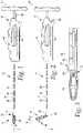
- FIG. 1is a side elevational view of one embodiment of an articulated instrument in accordance with the present disclosure, shown in a straight configuration;
- FIG. 2is a side elevational view of the articulated instrument of FIG. 1 , shown with the tip in an angled configuration;
- FIG. 3is a side elevational view of the distal end of the articulated instrument of FIG. 1 ;
- FIG. 4is a side elevational view of the distal end of the articulated instrument of FIG. 1 ;
- FIG. 5is a perspective view of the distal end if the articulated instrument of FIG. 1 , showing portions of the u-joint and the shaver in an articulated position that may be up to 120°;
- FIG. 6is an exploded view of the distal end of the articulated instrument of FIG. 1 ;
- FIG. 7is a cross-sectional view of the distal end of the articulated instrument of FIG. 1 ;
- FIG. 8is a cross-sectional view of the distal end portion of the articulated instrument of FIG. 1 ;
- FIG. 9is a cross-sectional view of the articulated instrument of FIG. 1 ;
- FIG. 10is an exploded view of the articulated instrument of FIG. 1 ;
- FIG. 11is a partial cross-sectional view of the handle of the articulated instrument of FIG. 1 that includes one embodiment of a free spin mechanism that may be employed in any of the articulated instruments of the present disclosure;
- FIG. 12is an exploded view of that free spin mechanism of FIG. 11 ;
- FIG. 12Ais an enlarged perspective view of the orientation tab and inner shaft
- FIG. 12Bis an enlarged side elevation view of the orientation tab and inner shaft
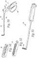
- FIG. 13is a perspective view of another embodiment of an articulated instrument in accordance with the present disclosure, shown in a straight configuration;
- FIG. 14is a perspective view of the articulated instrument of FIG. 13 , shown with the tip in an angled configuration;
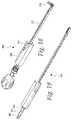
- FIG. 15is a perspective view of the working end or tool of the articulated instrument shown in a straight orientation:
- FIGS. 16 & 17are perspective views of the working end or tool of the articulated instrument of FIGS. 13-16 shown in an angular orientation;
- FIG. 18is a perspective view of another embodiment of the articulated instrument of the present disclosure wherein the instrument includes markings and an orientation indicator;
- FIG. 19is a perspective view of an articulated instrument without a distal handle attached to the inner shaft;
- FIG. 20Ais side elevation view of the distal end of the articulated instrument with the working end or tip in a straight configuration
- FIG. 20Bis a cross-sectional view that shows the relative position of the inner shaft within the internal mechanism of the handle;
- FIG. 21Ais perspective view of the distal end of the articulated instrument with the working end or tip in a straight configuration
- FIG. 21Bis a cross-sectional view that shows the relative position of the inner shaft within the internal mechanism of the handle
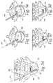
- FIG. 22is a perspective view of another embodiment of the articulated instrument.
- FIG. 23is a perspective view of a burr distal tip mounted an articulated instrument of the present disclosure.
- FIG. 24is a perspective view of the burr of FIG. 23 ;
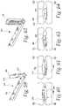
- FIG. 25is a perspective view of one embodiment of a detachable tip
- FIG. 26is a perspective of the detachable tip of FIG. 25 , shown attached to an articulated instrument of the present disclosure
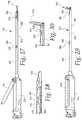
- FIG. 27is a side elevation view of another embodiment of an articulated instrument of the present disclosure, shown with the distal end in a straight configuration;
- FIG. 28is a side elevation view of the articulated instrument of FIG. 27 , shown with the distal end in a straight configuration;
- FIG. 29is a perspective view of one embodiment of a blade of the articulated instrument of FIG. 27 ;
- FIG. 30is a side elevation view of the articulated instrument of FIG. 27 , shown with the distal end in an angled configuration;
- FIG. 31is cross-sectional view of the instrument of FIG. 27 ;
- FIGS. 32 and 33are cross-sectional views of the handle of the instrument of FIG. 27 ;
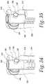
- FIGS. 34 and 35are perspective views of the proximal end of the handle of the instrument of FIG. 27 ;
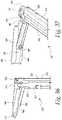
- FIGS. 36 and 37are perspective views of one embodiment of a tool that may be used with the instrument of FIG. 27 ;
- FIG. 38is a perspective view of another embodiment of an articulated instrument.
- FIGS. 39 and 40are perspective views of proximal end of the instrument of FIG. 27 ;
- FIG. 41is a perspective view of another embodiment of an articulated instrument.
- FIG. 42is a perspective view of the articulated instrument of FIG. 41 , shown with the tool in an angled configuration;
- FIG. 43is a perspective view of one embodiment of a tool
- FIG. 44is a perspective view of another embodiment of a tool.
- FIG. 45is an exploded view of the distal end of the articulated instrument of FIG. 27 , shown with the tool of FIG. 44 ;
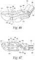
- FIG. 46is a perspective cut-away view of the tool of FIG. 43 which shows a motion limiter
- FIG. 47is a top plan partially cut-way view, showing the tool in a straight configuration
- FIG. 48is a top plan partially cut-way view, showing the blade in an angled configuration
- FIG. 49is a perspective view of another embodiment articulated instrument shown in a straight configuration
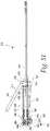
- FIG. 50is a plan view of another embodiment of an articulated instrument.
- FIG. 51is a perspective view another embodiment of a tool
- FIG. 52is a perspective view another embodiment of a tool
- FIG. 53is a perspective view of another embodiment articulated instrument
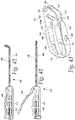
- FIG. 54is a perspective view of an articulated instrument within a disc space
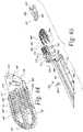
- FIGS. 55 and 56are perspective views of an articulated instrument within a disc space
- FIGS. 57 and 58are perspective views of an articulated instrument within a disc space
- FIG. 59is a perspective view of a distal end of one embodiment of an articulated instrument in an angled configuration
- FIGS. 60 and 61are schematic views showing the distal end of the articulated instrument of FIG. 59 within a disc space;
- FIG. 62is a perspective view of a distal end of one embodiment of an articulated instrument in an angled configuration
- FIGS. 63 and 64are schematic views showing the distal end of the articulated instrument of FIG. 62 within a disc space;
- FIG. 65is a perspective view of one embodiment of an articulated instrument having a distraction tip
- FIG. 66is a perspective view of the articulated instrument of FIG. 65 shown in the expanded configuration
- FIG. 67is a cross-sectional view of the articulated instrument of FIG. 65 ;
- FIG. 68is an enlarged cross-sectional view of the handle of the articulated instrument of FIG. 65 ;
- FIG. 69is a perspective view of the distal end of the articulated instrument of FIG. 65 shown in the compact configuration
- FIG. 70is a perspective view of the distal end of the articulated instrument of FIG. 65 shown in an expanded configuration.
- FIG. 71is an exploded view of the distraction tip of FIG. 65 .
- the articulated instrument 10includes a proximal end 12 and a distal end 14 .
- a handle 16At the proximal end 12 of the instrument 10 is a handle 16 , and an outer shaft 18 extends from the distal end of the handle 16 .
- a disruption tool 20such as a blade, shaver, rasp or any other suitable tool, may be located at the distal end 14 of the articulated instrument 10 .
- the distal end 14 of instrument 10may be inserted into the disc space between adjacent vertebrae and used to disrupt (cut, scrape, etc.) tissue within a disc space.
- the instrument 10may be used to cut disc tissue and/or scrape endplates.
- the disruption tool 20may be articulated so as to move the tool 20 between a straight configuration (as shown in FIG. 1 ), and an angled configuration relative to the axis A of the outer shaft 18 (as shown in FIG. 2 ).
- the tool 20also may be rotated about axis B ( FIG. 2 ) of the tool 20 as the tool is moved between the straight and angled configurations.
- the instrument 10may also include an orientation indicator, which indicates the angled position of the tool 20 relative to the axis of the outer shaft 18 during use.
- the indicatorincludes an orientation tab 22 associated with handle 16 . As shown in FIG.
- the tab 22is located in a first position when the tool 20 is in a straight configuration, and moves to a second position, as shown in FIG. 2 , as the tool 20 moves into an angled configuration.
- the tab 22may indicate the orientation of the tool 20 throughout the movement between the straight configuration and the angled configuration. This allows the user to position the tool at a selected angle.
- FIG. 9shows a cross-sectional view of the instrument 10 and FIG. 10 shows an exploded view.
- the instrument 10includes a handle 16 and an outer shaft 18 extending from the handle.
- the instrument 10also includes an inner shaft (drive shaft) 24 which extends through the handle 16 and the outer shaft 18 .
- a knob 25may be associated with the proximal end of the inner shaft 24 wherein the knob 25 may be gripped and turned by the user to rotate to shaft 24 .
- the outer shaft 18may be generally cylindrical or have a generally rectangular cross-section that substantially surrounds the inner shaft 24 .
- the outer shaft 18may at least partially surround the inner shaft 24 .
- the outer shaft 18may have a semi-circular cross-section that is positioned around the inner shaft 24 .
- the outer shaft 18includes windows 26 ( FIGS. 1 and 2 ), which allows for easy of cleaning of the shafts.
- the tool 20 of instrument 10is operably attached to the distal end 28 of the inner shaft 24 and the distal end 30 of the outer shaft 18 in a manner that allows the tool 20 to both move into an angled configuration and simultaneously rotate about its axis.
- the tool 20may initially be in a straight configuration as illustrated in FIG. 3 .
- the inner shaft 24moves linearly in a distal direction within the outer shaft 18 and handle 16 , the tool 20 moves into an angled configuration.
- the inner shaft 24moves linearly in a proximal direction
- the tool 20moves into the straightened configuration.
- the tool 20may be moved into any position that is between 0° and 120° relative to the axis A of the outer and inner shafts 18 , 24 .
- the tool 20may be positioned up in at a ranges of angles up to 75°, and in another embodiment, the tool may be positioned at a range of angles up to 60° relative to the axis A of the outer and inner shafts 18 , 24 . In yet another embodiment the tool may be positioned at a range up to 60° and beyond.
- rotating the inner shaft 24results in the tool 20 rotating about its axis B.
- the tool 20is hingedly connected to the inner shaft 24 by a universal joint (u-joint) 32 that translates rotational movement from the inner shaft 24 to the tool 20 to rotate the tool about its axis.
- the tool 20is connected to the inner shaft by a double u-joint or a double Cardan joint.
- a hinged lever joint 72hingedly connects the tool 20 to the distal end 30 of the outer shaft 18 .
- the hinged lever jointincludes a collar 34 .
- FIG. 6illustrates an exploded view of the distal end 14 of the instrument 10 ( FIG. 1 ), u-joint 32 and hinged joint.
- the double u-jointincludes a middle yoke 36 , a distal yoke 38 and a proximal yoke 40 .
- Two yoke spacers 42 and 44are used to connect the three yokes together with associated pins 46 .
- the proximal yoke 40is at the distal end 28 of the inner shaft 24 and the distal yolk 38 is at the proximal end of the tool 20 .
- the proximal yoke 38may be integral with the inner shaft 24 or may be attached to the inner shaft.
- the distal yoke 38may be attached to the tool 20 .
- the distal yoke 38may include a post 48 extending distally therefrom.
- the tool 20may include a bore 50 for receiving the post 48 .
- the post 48 and the tool 50may each include an opening 52 and 54 for receiving a pin 56 or other attachment member for attaching the tool 20 to the post 48 .
- Each spacer 42 and 44is hingedly connected the middle yoke 36 and hingedly connected to its respective proximal yoke 40 or distal yoke 38 .
- each spacer 42 and 44includes a side-to-side bore 58 and a top-to-bottom bore 60 .
- Each space 42 and 44is connected to its respective proximal yoke 40 or distal yoke 38 by pins 62 that pass through the arms 64 of the yoke 42 and 44 and the side-to-side bore 58 of the respective spacer 42 and 44 .
- Each spacer 42 and 44is connected to its respective side of the middle yoke 36 by pins 46 that pass through the respective arms 66 of the middle yoke 38 and the top-to-bottom bore 60 .
- pins 46include a passageway 68 that allows for the passage of pins 62 .
- pins 62may include a pin cap 70 to hold the pins in place.
- a hinged lever joint 72operatively connects the tool 20 to the distal end 30 the outer shaft 18 .
- the hinged lever joint 72may include a collar 34 that is placed around the post 48 of the distal yoke 38 .
- the collar 34includes one or more arms 74 that are hingedly connected to the distal end 30 of outer shaft 18 .
- the collar 34includes two arms 74 that are inserted into slots 76 of the outer shaft 18 and connected to the outer shaft by pin 78 .
- the hinged lever joint 72pivots moving the tool 20 into the angled configuration.
- the joint 72also allows the tool to rotate as it is moves through the angled positions.
- the inner shaft 24includes an external threaded portion 80 which engages and mates with an internal threaded element 82 that may be within the handle 16 .
- the external and internal thread portions 80 and 82define a drive mechanism 84 that moves the inner shaft 24 linearly in proximal and distal directions within the handle 16 and the outer shaft 18 .
- the drive mechanism 84coverts the rotational movement into linear movement and the inner shaft 24 is advanced distally.
- the inner shaft 24is rotated in the counterclockwise direction, the inner shaft 24 is moved proximally.
- the drive mechanism 84may be a free spine drive mechanism that allows the inner shaft 24 , and thus the tool 20 , to continuously rotate during use and when the inner shaft 24 reaches the end of travel in the proximal and distal directions.
- the outer shaft 18may include an enlarged proximal end 86 that is located within a bore of the distal end of the handle 16 .
- the free spin drive mechanism 84may be located within the enlarged proximal end 86 of the outer shaft 18 .
- the drive mechanism 84may include a middle drive sleeve 88 , a proximal drive ratchet ring 90 and a distal drive ratchet ring 92 .
- the middle drive sleeve 88may be held within the enlarged proximal end portion 86 of the outer shaft 18 by pins 94 .
- the outer surface of the middle drive sleeve 88may include a circumferential groove 96 that engages the pins 94 . This prevents axial movement of the middle drive sleeve 88 while allowing the drive sleeve to selectively rotate within the enlarged proximal end 86 of the outer sleeve 18 when the inner shaft 24 reaches its end of linear travel, as explained in more detail below.
- the middle drive sleeve 88includes a proximal end 98 and a distal end 100 , each of which include ratchet teeth 102 , 102 ′.
- the distal end 104 of the proximal drive ratchet ring 90includes unidirectional ratchet teeth 106 that are configured to mate with the unidirectional ratchet teeth 102 of proximal end 98 of the middle sleeve 88 .
- the proximal end 108 of the distal drive ratchet ring 92includes unidirectional ratchet teeth 110 that are configured to mate with the unidirectional ratchet teeth 102 ′ of the distal end 100 of the middle sleeve 88 .
- the distal drive ratchet ring 92is biased against the distal end 100 of the middle sleeve 88 so that the ratchet teeth are engaged and the proximal drive ratchet ring 90 is biased against the proximal end 98 of the middle sleeve 88 so that the ratchet teeth are engaged.
- the distal drive ratchet ring 92is biased by a spring 112 , such as a wave spring, positioned between the distal end of the distal ratchet ring 92 and a shoulder 114 of the outer shaft 18 .
- proximal drive ratchet ring 90is biased against the proximal end of the middle sleeve 88 so that the ratchet teeth are engaged.
- the proximal drive ratchetis biased by spring 116 positioned between the proximal end of the proximal ratchet ring 90 and a shoulder 118 of the handle 16 .
- Each of the middle sleeve 88 and the proximal and distal ratchet rings 90 and 92includes stops or limiters that limit the linear movement of the inner shaft 24 .
- the stopsare defined by pins 120 that pass through each of the respective middle sleeve 88 , and proximal and distal ratchet rings 90 and 92 .
- the pins 120 associated with the proximal and distal ratchet rings 90 and 92also prevent the ratchet rings from rotating.
- the pins 120 associated with ratchet rings 90 and 92are inserted through the holes 122 in the enlarged proximal end portion 86 of the outer shaft 18 .
- the holes 122are elongated to allow the ratchet rings 90 and 92 to move linearly within the enlarged proximal end portion 86 of the outer shaft 18 while preventing the rings from rotating.
- the distal ratchet ring 92 , the middle drive sleeve 88 and the proximal ratchet ring 90are held together by the wave spring washers 112 and 166 .
- the two ratchet rings 90 and 92have opposed unidirectional teeth orientation such that each provides a counter-torque to the other one.
- the middle sleeve 88being fix, allows the inner shaft 24 to move linearly in the proximal and distal directions as the inner shaft 24 is rotated within the middle sleeve 88 . As mentioned above the linear proximal and distal movement of the inner shaft 24 controls the angular motion of the tool 20 .
- the inner shaft 24moves distally until a distal shoulder 124 of the inner shaft 24 contacts the pin 120 associated with distal ratchet ring 92 .
- the inner shaft 24pushes against the pin 120 and moves the distal ratchet ring 92 so the ratchet teeth 110 , 102 ′ of the ring 92 and the middle sleeve 88 disengage, resulting in open the space between the ratchet teeth.
- the ratchet teeth 110 of the distal ring 92are disengaged, the counter torque is no longer applied at the distal end of the middle sleeve 88 and the unidirectional teeth 104 of the proximal ring 90 will allow the teeth 102 of middle sleeve 88 to slip passed the teeth 104 of the proximal ring 90 as the sleeve is rotated clockwise, the middle sleeve 88 is now allowed to rotate with the inner shaft 24 .
- the inner shaft 24is allowed to free spin and the tool 20 at the end of the inner shaft 24 is allowed to spin even after the inner shaft 24 has reached is distal linear limit.
- the ratchet teeth 104 of the proximal ring 90prevent the middle sleeve 88 from rotating counter clockwise.
- the inner shaft 24move proximally and the shoulder 124 disengages the pins 120 associated with the distal ratchet ring 92 .
- the spring 112moves the ratchet ring 92 back into engagement with the middle sleeve 88 , again applying a counter torque to the middle sleeve 88 .
- the inner shaft 24moves proximally until a proximal shoulder 126 of the inner shaft 24 contacts the pin 120 associated with the proximal ratchet ring 90 .
- the inner shaft 24pushes against the pin and moves the proximal ratchet ring 90 so the ratchet teeth 104 , 102 of the ring 90 and the middle sleeve 88 disengage, resulting in open the space between the ratchet teeth 104 , 102 .
- the ratchet teeth of the proximal ring 90are disengaged, the counter torque is no longer applied at the proximal end of the middle sleeve 88 and the unidirectional teeth 110 of the distal ring 92 are configured to allow the teeth 102 ′ of the middle sleeve 88 to slip passed the teeth 110 of the distal ring 92 as the middle sleeve 88 , the middle sleeve 88 is now allowed to rotate with the inner shaft 24 .
- the inner shaft 24is allowed to free spin and the tool 20 at the end of the inner shaft is allowed to spin even after the inner shaft 24 has reached its proximal linear limit.
- the ratchet teeth of the distal ring 92prevent the sleeve 88 from rotating clockwise.
- the inner shaft 24moves distally and the shoulder 126 disengages from the pins 120 associated with the proximal ratchet ring 90 .
- the spring 116moves the ratchet ring 90 back into engagement with the middle sleeve 88 , again applying a counter torque to the middle sleeve 88 .
- the free spin drive mechanism 84allows to user to rotate the tool 20 freely at the end of travel whether it is in a straight position or in an angular position to allow for good endplate preparation by allowing that free end of travel spinning and therefore rendering the articulated tool instrument to be more effective.
- FIGS. 12A and 12Bshow an enlarged view of the orientation tab 22 in association with the inner shaft 24 .
- the orientation tab 22includes a tab 130 extending from a u-shaped body 132 .
- the arms 134 of the u-shaped body 132are positioned about the inner shaft 24 .
- Pins 136hingedly attach the body 132 of the orientation tab 22 to the handle (not shown).
- the arms 134 of the body 132include a slot 138 which receives a pin 140 .
- the inner shaft 24includes a circumferential groove 142 which received the pin 140 .
- the position of the orientation tab 20corresponds to the angular position of the tool 20 ( FIGS. 1 and 2 ) to provide an indicator of the tool's position to the user.
- the articulated instrument 210includes a handle 212 , an outer shaft 214 , an inner shaft (drive shaft) 216 and a tool 218 at the distal end 220 of the instrument 210 .
- the tool 218may be any of the tools disclosed herein or any other suitable tool.
- the tool 218is a paddle shaver.
- the paddle shaverincludes a paddle or blade like shape with two openings 222 .
- the two openings 222may be used to gather the tissue as it is being cut with the sharp edge 224 , which may extend around partially or substantially around the periphery of the blade. As shown in FIGS.
- the tool 218may be moved into an angled configuration wherein the tool 218 is at an angle relative to the axis C of the outer and inner shafts 214 and 216 . Furthermore, the tool 218 also is able to rotate about its axis D as it is moved into and from the angled configuration.
- the toolmay be connected to the distal end 226 of the inner shaft 216 by a u-joint 228 .
- the u-jointransfers rotational movement for the inner shaft 216 to the tool 218 .
- the u-joint 228includes a distal yoke 230 associated with the tool 218 and a proximal yoke 232 associated with the distal end 234 of the inner shaft 216 .
- the u-jointfurther includes a spacer 236 ( FIG. 17 ) that is connected to the distal and proximal yokes 230 and 232 by pins 238 and 240 .
- the tool 218is also connected to the distal end 242 of the outer shaft 214 by a hinged lever joint 244 .
- the hinge lever joint 244includes a collar 246 attached to the tool 218 wherein the collar 246 allows the tool 218 to rotate therein.
- the hinged lever joint 244also includes an arm 248 extending from the collar 246 , wherein the arm 248 is hingedly attached to the outer shaft 214 by a pin 250 .
- FIGS. 16 and 17show the tool angulated at about 60° to the axis C of the inner and outer shafts 214 , 216 .
- 15 and 17identify the theoretical position of an implant in the disc space and are there to show that the angular motion of tool 218 sweeps across the whole area of the implant position that would be in a disc therefore allowing for substantially or complete removal of disc tissue in that area before the implant is inserted and deployed.
- FIGS. 20A and 20B and FIGS. 21A and 21Billustrate the drive mechanism 254 and the movement of the tool 218 as the inner shaft 216 is rotated and moved linearly.
- the drive mechanism 254includes a drive sleeve 256 which is held in handle 212 by pins 258 .
- the sleeve 256includes an internal thread 257 which mates with an external thread 259 on inner shaft 216 .
- pins 258serve as stops or limiters. For instance, in FIG.
- the action generated by the inner shaft's 216 forward/distal motiontranslates in the angulation of the tool 218 from a straight position in FIG. 20A to the angular position in FIG. 21A . So not only the rotation translates in a forward motion via drive mechanism 254 but the rotation also allows the tool to rotate as it swings in its angular motion about lever joint 244 via the u-joint 228 .
- the instrumentmay include a limited torque driver assembly associated with the inner shaft 216 .
- the limited torque driver assemblymay be any suitable limited torque driver assembly that allows the development of a torque motion in a controlled limited fashion.
- the articulated instrument 264includes an ergonomic handle 266 that has a visual indication of the orientation of tool angulation.
- the handle 266may include a rib 268 to indicate the orientation of the tool 270 angulation.
- markings 272may be on the outer shaft to provide a depth gage and, optionally, a visual indication of tool angulation. The markings 272 allow the physician to understand the positioning depth and, optionally, orientation of the tool 270 .
- FIG. 19illustrates another embodiment of the articulated instrument 274 without a proximal handle attached to the proximal end 276 of the inner shaft 278 .
- the proximal end 276 of the inner shaft 278has a quick connection element 280 , which may have the illustrated square configuration, which sometimes is referred to as a Square Quick-Connect.
- the quick connection element 280may be used to connected a variety of handle and/or torque drivers.
- FIG. 22shows another embodiment of an articulated instrument 282 , which may be an articulated shaver where the two motions, tool rotation 284 and angular motion 286 are decoupled and can each be separately activated with handle 288 controlling tool rotation 284 and handle 290 controlling angular motion 286 .
- the rotation and angular motioncan occur independently or the user and employ a two handed operation to obtain simultaneous motions.
- an articulated rotating burr 292is shown mounted on the distal end of an articulating instrument, such as any of the above described instruments.
- the rotating burr 292functions to the provide the user with the ability to grind away harder material such as osteophytes, bone spurs or other endplate irregularities in order to provide a very clean and even surface before deployment of an implant interbody fusion device.
- the burr 292has a cylindrical or conical shape with a blunt distal tip 294 with either set of parallel straight or helical cutting edges 296 extending along the length of a cylindrical or conical body.
- FIGS. 25 and 26illustrate a removable tool 298 that can be removed from the instrument 300 .
- the tool 298may be any suitable disruption tool, such as a burr, blade, shaver tips, scraper or rasp, that can be removable from the instrument.
- the tool 298may be attached by side set screw 302 that can be loosened to remove to replace the tool and re-tighten to attach a tool.
- the tool 298may include a slot 304 that accepts the screw 302 when the tool 298 is attached to the instrument 300 .
- the removable systemprovides a quick disconnect that allows the user to choose between a variety of tools and tool sizes.
- the removable toolcould be connected to the instrument in other manners, such as a snap ring or quick disconnect type of mechanism.
- FIGS. 27-37illustrates another embodiment of an articulated instrument 310 .
- the articulated instrument 310includes a handle 312 , a lever 314 , a cannula or shafts 316 and a tool 318 .
- the tool 318may be any tool described herein, such as a scraper, blade, rasp, etc.
- the split cannula 316may be made of two half shafts, a lower half shaft 320 and an upper half shaft 322 .
- the lower half shaft 320 and the upper half shaft 322are connected by pins 324 and are slidable relative to one another.
- the upper half shaft 322includes elongated slots 326 which the pins 324 are passed through and which allow the half shafts to slide relative to one another.
- the proximal end portion 328 of the upper half shaft 322 and the proximal end portion 330 of the lower half shaft 320are located in the handle 312 .
- the lever 314 associated with the handle 312is used to slide the lower half shaft 320 distally relative to the upper half shaft 322 .
- the lever 314includes an arm 332 and a base 334 .
- the base 334extends through an opening 336 in the handle 312 and through an opening 338 in the upper half shaft 322 .
- the base 334is attached to the handle 312 by pin 340 .
- the base 334 of the lever 314includes a u-shaped member 342 that engages slots 344 in the lower half shaft 320 .
- the lever 314pivots about pin 340 so that when the arm 332 of the lever 314 is moved toward the handle 312 , the u-shaped member 342 moves distally. Movement of the u-shaped member 342 distally results in moving the lower half shaft 320 distally.
- the lever 314is biased so that the arm 332 of the lever 314 is spaced from the handle 312 .
- the handle 312is biased by a spring 346 .
- a spring 346is positioned about the proximal end portion 330 of the lower half shaft 320 .
- the spring 346is also positioned between a head 348 at the proximal end 330 of the lower half shaft 320 and a wall 350 within the handled 312 . Referring to FIGS. 32 and 33 , in FIG. 32 , in the initial position, the lever 314 is biased by the spring 346 so that the arm 332 is positioned away from the handle 312 .
- the lever 314pivots about pin 340 and the u-shaped member 342 moves the lower half shaft 320 relative to the upper half shaft 322 . Additionally, when the lower half shaft 320 is moved distally, the head 348 at the proximal end 330 of the lower half shaft 320 moves distally and compresses the spring 346 . When pressure is relieved from the lever 314 , the spring 346 biases the lower half shaft 320 to move proximally back to its initial position, thereby moving the lever 314 back to its initial position.
- the instrumentmay include a releasable lock that locks the instrument in the second position.
- the lock 352is a spring release lock that includes a button 354 and a post 356 extending therefrom and into the handle 312 .
- the post 356also extends through a slot 358 in the head 348 of the lower half shaft 320 .
- the lock 352is biased downward by a spring 360 that is positioned between the button 354 and the handle 312 .
- the handle 312may include a visual indicator indicating the position of the lower half shaft and the position of the tool.
- the proximal end of the handle 312includes an opening or bore 370 in which the proximal end 330 of the lower half shaft 320 is located.
- the instrumentis in its initial position.
- the proximal end 330 of the lower half shaft 320is below the outer surface of the handle 312 , the lower half shaft 320 has been moved distally which in turn indicates that the tool has been moved into a second position.
- a tool 318such as a scrapping blade, is located at the distal end of the instrument 310 .
- the tool 318is hingedly attached to the upper half shaft 322 by pin 372 and attached to the lower half shaft 320 by pin 374 .
- the distal end of the upper half shaft 322includes a u-shaped connection element 376 and the distal end of the lower half shaft 320 includes a u-shaped connection element 378 .
- the toolincludes a u-shaped bracket 380 which includes a portion that is located within the u-shaped connection element 376 of the upper half shaft 322 and a portion located within the u-shaped connection element 378 of the lower half shaft 320 .
- a blade 382is positioned between the u-shaped bracket 380 of the tool 380 and hingedly connect to the bracket 380 by pin 384 .
- the blade 382that can pivot about pin 384 so the double scraping edge of the blade 386 and 386 ′ are maintained in contact with the endplate for optimize scraping (one at the time based on the bias of the user toward the superior or inferior endplate).
- the blade 382can fully rotate about the pivot 384 but it could also be made to have a limited motion about pivot 384 with some stop posts to prevent full rotation of the blade 382 (not shown).
- the lever 314When the tool 318 is to be moved to 90° relative to the axis of half shafts 320 , 322 , the lever 314 is moved toward the handle 312 which moves the lower half shaft 320 distally relative to the upper half shaft 322 .
- the tool 318pivots around pin 372 associated with the upper half shaft 322 and pin 374 associated with the lower half shaft 320 , thereby moving the tool 318 into a portion that is 90° relative the axis of the half shafts.
- FIG. 38illustrates another embodiment of an articulated instrument 388 which includes a u-shaped flipping lock 390 which is pivoted about the distal end of the handle 312 .
- the lock 390is pivoted to cover the lever 314 and hold it in position. The lock 390 can then be pivot to uncover and release the lever 314 .
- FIGS. 39 and 40show the lock 390 in combination with a visual indicated as discussed above.
- FIGS. 41 and 42show another embodiment of an articulated instrument 400 .
- the upper and lower half shafts 402 and 404interact with each other in the same manner as described above.
- lever 406is associated with handle 408 and the lower half shaft 404 in the same manner as described above.
- the handle 408includes windows or holes 410 which allows for less material and a lighter handle.
- FIG. 43-45illustrate embodiment of tools 412 and 414 that may be used with any of the instruments shown in FIGS. 27-42, 49, 51 and 53 .
- the tools 412may include different components that are assembled together to provide movement and adjustability.
- the tools 412 and 414include a bracket 416 , 416 ′ and a working piece 418 , 418 ′ that may pivot relative to the bracket 416 , 416 ′.
- the proximal end 420 , 420 ′ of the bracketmay be mounted or attached to the distal end of an instrument 422 ( FIG. 45 ).
- the bracketincludes a pair of arms 424 , 424 ′ that may be mounted to the upper and lower half shafts 426 , 428 of the instrument 422 .
- the upper and lower half shafts 426 , 428are connected by a pin 430 that extends through elongated opening 432 in the upper half shaft 426 and connects to lower half shaft 428 .
- the lower half shaft 428moves linearly relative to the lower half shaft 426 .
- each of the arms 424 , 424 ′ of the brackets 416 , 416 ′includes lower opening 434 , 434 ′ which may be mounted to the lower half shaft 428 with a pin 436 .
- Each of the arms 424 , 424 ′ of the brackets 416 , 416 ′includes an upper opening 438 , 438 ′ which may be mounted to the lower half shaft 428 with a pin 440 .
- the upper openings 438 , 438 ′are elongated so as to allow the pin 440 to slide within the opening as the tool is moved into the angled configuration.
- the arms 424 , 424 ′are placed on either side of the lower half shaft 428 and upper half shaft 426 and pins 436 and 440 extends through arms to attached them to the half shafts.
- the tool 412is in the straight configuration and the pin 440 is located at the upper end of the elongated opening 438 .
- the pin 440slides within the opening 438 to the other end of the elongated opening.
- each working piece 418 , 418 ′includes three arms 444 , 444 ′ for attachment to the distal end 446 , 446 ′ of its respective bracket 416 , 416 ′, which includes two arms 448 , 448 ′.
- Each working piece 418 , 418 ′is attached to its respective bracket 416 , 416 ′ by meshing the three arms 444 , 444 ′ of the working piece 418 , 418 ′ with the two arm 448 , 448 ′ of the bracket 416 , 416 ′.
- a pin 450 , 450is then inserted through the three arms 444 , 444 ′ of the working piece 418 , 418 ′.
- the working piecemay pivot about the pin during use.
- the working piecehas the ability to pivot about + or ⁇ 30° relative to the bracket. This assists in the working piece being more compliant to the surface of the endplate having an optimize contact over the full length of the blade or the rasp.
- the tool 412 , 412 ′may include a limiter 452 , 452 ′ that limits the movement of the working piece 418 , 418 ′.
- the limiterincludes a distal end 454 , 454 ′ that contacts the working piece 418 , 418 ′ or pin 450 , 450 ′ to limit the range of pivoting of the working piece about pin 450 , 450 ′.
- the limiter 452 ′includes a proximal end 456 ′ that has an upper opening 458 ′ and a lower opening 460 ′, which are similar in size and shape to openings 434 ′ and 438 ′ of the bracket ' 416 .
- the limiter 452 ′is placed between the arms 424 ′ of the bracket 416 ′ and the proximal end of the limiter 452 ′ is placed between arms of the upper and lower half shafts 426 , 428 .
- the limiter 452 ′is attached to the upper and lower half shafts 426 , 428 by pins 436 and 440 .
- the limiter 452is slightly off-set during the articulation leaving a gap 453 where the pin 450 has the necessary opening to pivot as the distal end of 454 of the limiter 452 is not in contact with a flat the pin 450 as also.
- This opening gapallows the scraper or rasp working piece to pivot about the axis of pin 450 until edge contact between the distal end of the limiter 452 and the flat of pin 450 .
- the gap( 453 of FIG. 48 ) is closed in the straight configuration. This action can be accomplished by adjusting the ramp angle of the upper elongated opening of the limiter (e.g. 458 ′ of FIG. 45 ) to be slightly different than the ramp angle of the elongated opening 438 ( FIG. 47 ) of the bracket 416 .
- FIG. 49illustrates another embodiment of an articulated instrument 470 .
- the handle 472includes a rotating knob 474 to articulate the tool 476 instead of a lever mechanism as previously described.
- the benefit of the rotating knob 474is that the user would be able to control the angle of the tool 476 .
- the knob 474may have a multiple intermediary positions as shown by the slots 478 that could be for position at 0 and every 15° thereafter all the way to 90° for instance. Other increments could be used as well.
- FIG. 51illustrates another embodiment of an articulated instrument 480 that includes a pistol like grip device 482 .
- the grip 482may include a first handle 484 and a second handle 486 that a pivoted relative to one another.
- the first handle 484may be connected to the upper half shaft 488 and the second handle 486 may be connected to the lower half shaft 490 .
- the handles 484 and 486When the handles 484 and 486 are moved toward each other, the lower half shaft 490 moves distally relative to the upper half shaft 488 .
- the handlesmay be biased apart by a spring 492 .
- FIG. 52 a and FIG. 18 bare enlarged views of tools 494 and 496 that are of a one-piece construction and include different rasp patterns.
- Tool 494includes rows of teeth having an angled configuration 53 that would provide rasping action (tissue/cartilage removal) in one direction (in this illustrated orientation, it would be from a posterior to an anterior direction).
- Tool 496includes teeth that are more universal and pyramid shaped like allowing tissue removal in all directions.
- FIG. 53illustrates the one-piece construction tool 494 attached to an instrument 498 , which may be used during a discectomy for the final preparation of the endplate to smooth out the surface in order to clear out any irregularities, extra tissue, small osteophytes and cartilage defects or imperfection that could prevent the insertion of an interbody implant device.
- the instrumentis an articulated instrument, such as those described about with respect to FIGS. 27-45
- the disclosed instrumentationmay be used during the discectomy part of a greater procedure for fusion or disc replacement by the placement of an interbody implant device.
- the disclosed instrumentationmay also be used to remove tissue from other parts of the body.
- the disclosed instrumentsmay be used in disc preparation procedures where an incision would be made in the annulus, followed by the removal of a cut-out window in the annulus, which may be about 10 mm wide, and the height of the disc at that particular level.
- any of the articulated instruments described hereinmay be used to penetrate the nucleus 503 in a straight fashion in line with the access axis. Once that instrument is inserted, it is then rotated (the entire instrument is rotated so the tip blade cuts out the tissue without lateral or angular motion) about the axis to debulk the nucleus tissue, a standard tissue grasper such as a pituitary tool may be used to remove some of the tissue bulk before the next step is taken.
- a standard tissue graspersuch as a pituitary tool may be used to remove some of the tissue bulk before the next step is taken.
- instrument 10may be used to create a larger space to accommodate the implantation of an interbody implant, such as a fusion device or a disc replacement device.
- an interbody implantsuch as a fusion device or a disc replacement device.
- the knob 24 of the instrument 10the tool 20 , which may be a shaver, will rotate as well as swept across the area 500 in the disc space as shown in FIG. 54 and in a manner as previously disclosed and this action can be repeated several times with the use of pituitary tools in between for tissue removal until the physician feels that the majority or most of the nucleus tissue is removed.
- Instrument 10has the ability to clean-out a large area away from the axis of insertion 504 without any motion of the instrument itself, unlike a standard shaver that needs to be sway back and forth in order to reach the same surfaced area and in some cases, could not be able to because of interference with body structure 506 or with the supporting access devices such as retractor or spreader (not shown).
- body structure 506or with the supporting access devices such as retractor or spreader (not shown).
- the ability to sway a discectomy instrumentmay not be available or desired.
- the next stepis the preparation of the end plate 508 .
- the articulated instrument 510is used to remove further tissue that is still attached to the endplate in the same general area of where the nucleus was removed as it is shown in FIGS. 55 and 56 . Again the instrument is inserted in the straight configuration ( FIG. 55 ) along axis 504 and then the tool 512 is angled into an angled configuration ( FIG. 56 ). The instrument 510 can then can be moved back and forth ( FIG. 56 ) in a motion from posterior to anterior and until a sufficient amount of tissue is removed. The loose tissue can be aspirated or removed with pituitary tools as well.
- the surface preparation of the endplatecan be completed by using an articulated instrument 514 that includes an articulated rasp 516 .
- the instrumentmay be inserted and used in the same manner as shown in FIGS. 55 and 56 .
- the spacecan be sized and the appropriate interbody implant, such as a fusion device or disc replacement implant can be inserted and the procedure completed.
- interbody implantsuch as a fusion device or disc replacement implant
- FIGS. 59-61illustrate the use of articulated instrument 310 of FIGS. 27-37 .
- the instrument 310is inserted into the disc space 520 in a straight configuration and then the tool 318 , such as a pivoting curette or blade, is moved into an angle configuration relative to shaft 316 .
- the shaft 316is rotated so that the blade 382 of the tool 318 contacts the endplates 522 .
- the blade 382may pivot relative to the bracket 380 .
- the shaftis moved back and forth to shave tissue from the endplates 522 .
- FIGS. 62-63illustrate the use of articulated instrument 498 of FIG. 53 .
- the instrument 498is inserted into the disc space 520 in a straight configuration and then the tool 494 , such as a rasp, is moved into an angle configuration relative to shaft.
- the shaftis rotated so that the tool 494 contacts the endplates 522 .
- the shaftis moved back and forth to shave tissue from the endplates 522 .
- FIGS. 65-71illustrate another embodiment of an articulated instrument 530 wherein the tool is a distraction tool 532 that may be used to move tissue apart, such as to distract adjacent vertebral bodies.
- the instrument 530includes a handle 534 , an outer shaft 536 , an inner shaft 538 (drive shaft) and the distraction tool 532 .
- the instrument 530uses a hybrid combination of a lever 540 to control the linear movement of the inner shaft 538 and a u-joint 542 to translate rotational movement to the tool 532 .
- the distraction tool 532may be angled up to 60°, relative to the axis of the shafts 536 , 538 , using a single U-Joint (such as that shown in FIGS.
- the rotational movement transferred to the distraction tool 532may be used to expand the tool, as shown in FIGS. 66 and 70 .
- FIG. 67illustrates a full cross-section of the entire instrument 530 and FIG. 68 is an enlarged cross-sectional view of the handle 534 .
- the inner shaft 538extends through the handle 534 and the outer shaft 536 .
- a knob 544 for turning the inner shaft 538is located at the proximal end of the shaft 538 .
- the handle 534includes lever 540 , which has similar structures and operates in the same manner as lever 314 shown in FIG. 31 .
- the lever 540includes a body 546 that has an extension 548 , such as one or more arms, that mates with a groove 550 in the inner shaft 538 ( FIG. 68 ).
- the engagement between the extension 548 and groove 550allows the shaft 538 to rotate within the handle.
- the inner shaft 538is biased to the proximal position by a spring 552 , which is located between a wall 554 of the handle 534 and a shoulder 556 extending radially outward from the shaft 538 .
- the operation of the lever 540is very similar to that shown in FIGS. 31-33 .
- the lever 540is biased so that the arm 558 of the lever 540 is spaced from the handle 534 (the instrument is not shown in this position).
- the lever 540pivots about pin 560 and the extension 548 of the handle body 546 moves the inner shaft 538 distally relative to the outer shaft 536 .
- the shoulder 556 at the proximal end of the inner shaft 538moves distally and compresses the spring 552 .
- the spring 552biases the inner shaft 538 to move proximally back to its initial position, thereby moving the lever 540 back to its initial position.
- the inner shaft 538is rotated by knob 544 to provide rotating action to the distal distraction tool 532 , while the lever 540 provides the articulation of the tool.
- An indicator tab 562may be used to indicate the orientation of the tool 532 in a similar fashion as previously discussed with respect to indicator tab 22 and as shown in FIGS. 12A and 12B .
- FIG. 71illustrates an exploded view of the distraction tool 532 .
- the toolincludes an upper member 570 , a lower member 572 and a middle member 574 .
- the upper member 570is generally u-shaped and includes an upper plate or surface 576 for contacting tissue. In the illustrated embodiment, the upper surface 576 is shown a flat but in other embodiment, the upper surface 576 may be curved or textured.
- the upper member 570includes a pair of opposed side walls 578 extending downward form the upper surface 576 .
- the inner surface of the opposed side walls 578include a plurality of angled ramps 580 . In one embodiment the ramps 580 are angled at 45°.
- the lower member 572includes a lower plate or surface 582 which a pair of opposed arms 584 extending upward form the lower surface 582 .
- the opposed arms 584are spaced inward of the edges of the lower surface 582 .
- the outer surface of the opposed arms 584include a plurality of ramps 586 that are angled in the opposite direction from the ramps 580 of the upper member 570 . In one embodiment the ramps 586 are angled at 45° in the opposite direction from the ramps 580 of the upper member 570 .
- the middle member 574includes a front wall 588 and a pair of opposed arms 590 extending from the front wall.
- the inner surface of the opposed arms 590include a plurality of ramps 592 that are angled in the opposite direction from the ramps 586 of the lower member 572 .
- the lower member 572 and middle member 574are configured to mate such that the arms 584 of the lower member 572 are placed inside of the arms 590 of the middle member 574 and the ramps 586 of the lower member 572 are positioned in the space 594 between or adjacent to the ramps 592 of the inner surface of the middle member 574 .
- the ramps 592are positioned in the space 596 between the ramps 586 of the lower member.
- the outer surface of the arms 590 of the middle member 574include ramps 598 that are angled in the opposite direction from the ramps 580 of the upper member 570 .
- the upper member 570 and middle member 574are configured to mate such that the arms 578 of the upper member 570 are placed outside of the arms 590 of the middle member 574 and the ramps 580 of the upper member 570 are positioned in the space 600 between the ramps 598 of the outer surface of the middle member 574 .
- the upper member 270 and lower member 274each include a slot 602 (not shown in the upper member) that receives a rail 604 ( FIG. 70 ) vertically positioned within the slots.
- the distraction tool 532includes an actuation member 606 , which is includes external threads 608 on distal end and a yoke 610 on the proximal end.
- the yoke 610attaches to or is a part of the u-joint 542 , such as a u-joint or double u-joint as described above.
- the external threads 608 on the distal end of the actuation member 606engage internal threads 612 of a bore 614 through the front wall 588 of the middle member 574 .
- the distraction tool 532also includes a hinged lever 616 that is attached to the outer shaft 536 .
- the hinged lever 616is similar to hinged lever 34 shown in FIGS. 4-6 .
- the hinged lever 616includes a collar 618 having a pair of arms 620 extending therefrom.
- the collar 618is located about actuation member 606 and the arms 620 are hingedly attached to the outer shaft 736 by a pin 622 ( FIGS. 69 and 70 ).
- the distraction tool 532is inserted into a disc space in the straight configuration.
- the lever 540is moved toward the handle 534 to move the distraction tool 532 into an angled configuration.
- the knob 544is used to rotate inner shaft 538 wherein the rotating motion is translated via the u-joint or double U-joint 542 to the actuation member 606 of the distraction tool.
- the engagement of the threaded distal end 608 of the actuation member 606 with the internal threads 612 of the middle member 574pulls the middle member 574 proximally relative to the upper and lower member 570 , 572 .
- the ramps 592 , 598 of the middle member 574act upon the corresponding ramps 580 , 586 on the upper member 570 and the lower member 572 to spread apart the upper and lower members.
- the upper member and lower member 570 , 572move in a vertical direction as they are guided by rail 604 with the corresponding engagement on each of the upper member and lower member.
- the inner shaft 538is rotated in the other direction to move the middle member 574 distally, which in turn moves the upper and lower member 570 , 572 back toward the unexpanded configuration shown in FIG. 69 .
Landscapes
- Health & Medical Sciences (AREA)
- Life Sciences & Earth Sciences (AREA)
- Engineering & Computer Science (AREA)
- Biomedical Technology (AREA)
- Surgery (AREA)
- Orthopedic Medicine & Surgery (AREA)
- Heart & Thoracic Surgery (AREA)
- Animal Behavior & Ethology (AREA)
- General Health & Medical Sciences (AREA)
- Public Health (AREA)
- Veterinary Medicine (AREA)
- Molecular Biology (AREA)
- Medical Informatics (AREA)
- Nuclear Medicine, Radiotherapy & Molecular Imaging (AREA)
- Oral & Maxillofacial Surgery (AREA)
- Transplantation (AREA)
- Neurology (AREA)
- Cardiology (AREA)
- Vascular Medicine (AREA)
- Dentistry (AREA)
- Physical Education & Sports Medicine (AREA)
- Pathology (AREA)
- Surgical Instruments (AREA)
Abstract
Description
Claims (20)
Priority Applications (2)
| Application Number | Priority Date | Filing Date | Title |
|---|---|---|---|
| US17/023,312US11471145B2 (en) | 2018-03-16 | 2020-09-16 | Articulated instrumentation and methods of using the same |
| US17/930,559US12357291B2 (en) | 2018-03-16 | 2022-09-08 | Articulated instrumentation and methods of using the same |
Applications Claiming Priority (3)
| Application Number | Priority Date | Filing Date | Title |
|---|---|---|---|
| US201862644101P | 2018-03-16 | 2018-03-16 | |
| PCT/US2019/022632WO2019178575A1 (en) | 2018-03-16 | 2019-03-15 | Articulated instrumentation and methods of using the same |
| US17/023,312US11471145B2 (en) | 2018-03-16 | 2020-09-16 | Articulated instrumentation and methods of using the same |
Related Parent Applications (1)
| Application Number | Title | Priority Date | Filing Date |
|---|---|---|---|
| PCT/US2019/022632ContinuationWO2019178575A1 (en) | 2018-03-16 | 2019-03-15 | Articulated instrumentation and methods of using the same |
Related Child Applications (1)
| Application Number | Title | Priority Date | Filing Date |
|---|---|---|---|
| US17/930,559ContinuationUS12357291B2 (en) | 2018-03-16 | 2022-09-08 | Articulated instrumentation and methods of using the same |
Publications (2)
| Publication Number | Publication Date |
|---|---|
| US20210169459A1 US20210169459A1 (en) | 2021-06-10 |
| US11471145B2true US11471145B2 (en) | 2022-10-18 |
Family
ID=67907274
Family Applications (2)
| Application Number | Title | Priority Date | Filing Date |
|---|---|---|---|
| US17/023,312ActiveUS11471145B2 (en) | 2018-03-16 | 2020-09-16 | Articulated instrumentation and methods of using the same |
| US17/930,559ActiveUS12357291B2 (en) | 2018-03-16 | 2022-09-08 | Articulated instrumentation and methods of using the same |
Family Applications After (1)
| Application Number | Title | Priority Date | Filing Date |
|---|---|---|---|
| US17/930,559ActiveUS12357291B2 (en) | 2018-03-16 | 2022-09-08 | Articulated instrumentation and methods of using the same |
Country Status (2)
| Country | Link |
|---|---|
| US (2) | US11471145B2 (en) |
| WO (1) | WO2019178575A1 (en) |
Cited By (6)
| Publication number | Priority date | Publication date | Assignee | Title |
|---|---|---|---|---|
| US11771483B2 (en) | 2017-03-22 | 2023-10-03 | Spinal Elements, Inc. | Minimal impact access system to disc space |
| USRE49994E1 (en) | 2013-03-14 | 2024-06-04 | Spinal Elements, Inc. | Spinal fusion implants and devices and methods for deploying such implants |
| US12053196B2 (en) | 2014-07-08 | 2024-08-06 | Spinal Elements, Inc. | Apparatus and methods for disrupting inter vertebral disc tissue |
| US12121456B2 (en) | 2015-02-06 | 2024-10-22 | Spinal Elements, Inc. | Graft material injector system and method |
| US12207856B2 (en) | 2018-01-29 | 2025-01-28 | Spinal Elements, Inc. | Minimally invasive interbody fusion |
| US12357291B2 (en) | 2018-03-16 | 2025-07-15 | Spinal Elements, Inc. | Articulated instrumentation and methods of using the same |
Families Citing this family (6)
| Publication number | Priority date | Publication date | Assignee | Title |
|---|---|---|---|---|
| EP4368128A3 (en) | 2016-09-07 | 2024-07-17 | Vertos Medical, Inc. | Percutaneous lateral recess resection methods and instruments |
| CN118042995A (en)* | 2021-09-22 | 2024-05-14 | 脊柱外科策略有限公司 | Surgical instrument |
| US11998221B2 (en)* | 2021-11-23 | 2024-06-04 | Life Spine, Inc. | Articulating curette for decorticating a vertebral endplate via a cannula |
| US20230404561A1 (en) | 2022-06-16 | 2023-12-21 | Vertos Medical, Inc. | Integrated instrument assembly |
| DE102022119979A1 (en)* | 2022-08-09 | 2024-02-15 | Aesculap Ag | Medical motor handpiece for 2-in-1 operation and medical hand instrument with 2-in-1 operation |
| CN119112305A (en)* | 2024-10-24 | 2024-12-13 | 上海凯利泰医疗科技股份有限公司 | A medical scraper |
Citations (389)
| Publication number | Priority date | Publication date | Assignee | Title |
|---|---|---|---|---|
| US2002021A (en) | 1934-02-27 | 1935-05-21 | Rouse Howard | Surgical fracture extension appliance |
| US3807390A (en) | 1972-12-04 | 1974-04-30 | American Optical Corp | Fiber optic catheter |
| US4846175A (en) | 1986-12-18 | 1989-07-11 | Erintrud Frimberger | Probe for introduction into the human or animal body, in particular a papillotome |
| US4862891A (en) | 1988-03-14 | 1989-09-05 | Canyon Medical Products | Device for sequential percutaneous dilation |
| US4863476A (en) | 1986-08-29 | 1989-09-05 | Shepperd John A N | Spinal implant |
| US4898161A (en) | 1986-12-05 | 1990-02-06 | S+G Implants Gmbh | Forceps for pushing apart vertebrae |
| US5129889A (en) | 1987-11-03 | 1992-07-14 | Hahn John L | Synthetic absorbable epidural catheter |
| US5192327A (en) | 1991-03-22 | 1993-03-09 | Brantigan John W | Surgical prosthetic implant for vertebrae |
| US5201742A (en) | 1991-04-16 | 1993-04-13 | Hasson Harrith M | Support jig for a surgical instrument |
| US5219358A (en) | 1991-08-29 | 1993-06-15 | Ethicon, Inc. | Shape memory effect surgical needles |
| DE4222121C1 (en) | 1992-07-06 | 1993-09-30 | Kernforschungsz Karlsruhe | Multidirectional trocar for examining inaccessible location or as endoscope instrument for min. invasive surgery - has flexible distal end section with adjacent hollow cylindrical pivot segments deflected under control of tension cable |
| US5267994A (en) | 1992-02-10 | 1993-12-07 | Conmed Corporation | Electrosurgical probe |
| US5306310A (en) | 1991-08-27 | 1994-04-26 | Man Ceramics Gmbh | Vertebral prosthesis |
| US5342394A (en) | 1990-05-16 | 1994-08-30 | Olympus Optical Co., Ltd. | Apparatus for blocking a vein branch and method of blocking a vein branch |
| US5345945A (en) | 1990-08-29 | 1994-09-13 | Baxter International Inc. | Dual coil guidewire with radiopaque distal tip |
| US5366490A (en) | 1992-08-12 | 1994-11-22 | Vidamed, Inc. | Medical probe device and method |
| US5374267A (en) | 1992-02-17 | 1994-12-20 | Acromed B.V. | Device for fixing at least a part of the human cervical and/or thoracic vertebral column |
| US5383884A (en) | 1992-12-04 | 1995-01-24 | American Biomed, Inc. | Spinal disc surgical instrument |
| US5397304A (en) | 1992-04-10 | 1995-03-14 | Medtronic Cardiorhythm | Shapable handle for steerable electrode catheter |
| US5397364A (en) | 1993-10-12 | 1995-03-14 | Danek Medical, Inc. | Anterior interbody fusion device |
| US5423806A (en) | 1993-10-01 | 1995-06-13 | Medtronic, Inc. | Laser extractor for an implanted object |
| US5433739A (en) | 1993-11-02 | 1995-07-18 | Sluijter; Menno E. | Method and apparatus for heating an intervertebral disc for relief of back pain |
| US5445639A (en) | 1989-05-10 | 1995-08-29 | Spine-Tech, Inc. | Intervertebral reamer construction |
| EP0682910A1 (en) | 1994-05-19 | 1995-11-22 | Friedrich Tieber | Instrument for the percutaneous treatment of organic tissue |
| US5470043A (en) | 1994-05-26 | 1995-11-28 | Lockheed Idaho Technologies Company | Magnetic latching solenoid |
| US5487757A (en) | 1993-07-20 | 1996-01-30 | Medtronic Cardiorhythm | Multicurve deflectable catheter |
| US5500012A (en) | 1992-07-15 | 1996-03-19 | Angeion Corporation | Ablation catheter system |
| US5540696A (en) | 1995-01-06 | 1996-07-30 | Zimmer, Inc. | Instrumentation for use in orthopaedic surgery |
| US5549679A (en) | 1994-05-20 | 1996-08-27 | Kuslich; Stephen D. | Expandable fabric implant for stabilizing the spinal motion segment |
| US5554163A (en) | 1995-04-27 | 1996-09-10 | Shturman Cardiology Systems, Inc. | Atherectomy device |
| US5571147A (en) | 1993-11-02 | 1996-11-05 | Sluijter; Menno E. | Thermal denervation of an intervertebral disc for relief of back pain |
| US5599346A (en) | 1993-11-08 | 1997-02-04 | Zomed International, Inc. | RF treatment system |
| US5697909A (en) | 1992-01-07 | 1997-12-16 | Arthrocare Corporation | Methods and apparatus for surgical cutting |
| US5716416A (en) | 1996-09-10 | 1998-02-10 | Lin; Chih-I | Artificial intervertebral disk and method for implanting the same |
| US5718707A (en) | 1997-01-22 | 1998-02-17 | Mikhail; W. E. Michael | Method and apparatus for positioning and compacting bone graft |
| WO1998017190A2 (en) | 1996-10-23 | 1998-04-30 | Oratec Interventions, Inc. | Method and apparatus for treating intervertebral discs |
| US5755661A (en) | 1993-06-17 | 1998-05-26 | Schwartzman; Alexander | Planar abdominal wall retractor for laparoscopic surgery |
| US5755797A (en) | 1993-04-21 | 1998-05-26 | Sulzer Medizinaltechnik Ag | Intervertebral prosthesis and a process for implanting such a prosthesis |
| US5755732A (en) | 1994-03-16 | 1998-05-26 | United States Surgical Corporation | Surgical instruments useful for endoscopic spinal procedures |
| US5788713A (en) | 1994-07-22 | 1998-08-04 | University Of Washington | Method and apparatus for stereotactic implantation |
| WO1998034552A1 (en) | 1997-02-06 | 1998-08-13 | Surgical Dynamics | Expandable non-threaded spinal fusion device |
| US5851214A (en) | 1994-10-07 | 1998-12-22 | United States Surgical Corporation | Surgical instrument useful for endoscopic procedures |
| US5871501A (en) | 1994-01-18 | 1999-02-16 | Datascope Investment Corp. | Guide wire with releasable barb anchor |
| US5885217A (en) | 1995-01-20 | 1999-03-23 | Tyco Group S.A.R.L. | Catheter introducer |
| WO1999021500A1 (en) | 1997-10-27 | 1999-05-06 | Saint Francis Medical Technologies, Llc | Spine distraction implant |
| US5916166A (en) | 1996-11-19 | 1999-06-29 | Interventional Technologies, Inc. | Medical guidewire with fully hardened core |
| DE19710392C1 (en) | 1997-03-13 | 1999-07-01 | Haehnel Michael | Slipped disc implant comprises an extensible, hinged or wound body |
| US5919235A (en) | 1995-11-08 | 1999-07-06 | Sulzer Orthopaedie Ag | Intervertebral prosthesis |
| WO1999047058A2 (en) | 1998-03-19 | 1999-09-23 | Oratec Interventions, Inc. | Catheter for delivery of energy to a surgical site |
| US5980471A (en) | 1997-10-10 | 1999-11-09 | Advanced Cardiovascular System, Inc. | Guidewire with tubular connector |
| US5980504A (en) | 1996-08-13 | 1999-11-09 | Oratec Interventions, Inc. | Method for manipulating tissue of an intervertebral disc |
| US6007570A (en) | 1996-08-13 | 1999-12-28 | Oratec Interventions, Inc. | Apparatus with functional element for performing function upon intervertebral discs |
| US6019765A (en) | 1998-05-06 | 2000-02-01 | Johnson & Johnson Professional, Inc. | Morsellized bone allograft applicator device |
| US6039761A (en) | 1997-02-12 | 2000-03-21 | Li Medical Technologies, Inc. | Intervertebral spacer and tool and method for emplacement thereof |
| US6059829A (en) | 1995-03-08 | 2000-05-09 | Synthese | Intervertebral implant |
| US6099514A (en) | 1996-08-13 | 2000-08-08 | Oratec Interventions, Inc. | Method and apparatus for delivering or removing material from the interior of an intervertebral disc |
| US6126660A (en) | 1998-07-29 | 2000-10-03 | Sofamor Danek Holdings, Inc. | Spinal compression and distraction devices and surgical methods |
| WO2000074605A1 (en) | 1999-06-02 | 2000-12-14 | Henry Graf | Intervertebral implant and assembly for setting same |
| US6183517B1 (en) | 1998-12-16 | 2001-02-06 | Loubert Suddaby | Expandable intervertebral fusion implant and applicator |
| US6224630B1 (en) | 1998-05-29 | 2001-05-01 | Advanced Bio Surfaces, Inc. | Implantable tissue repair device |
| US6228022B1 (en) | 1998-10-28 | 2001-05-08 | Sdgi Holdings, Inc. | Methods and instruments for spinal surgery |
| US6245072B1 (en) | 1995-03-27 | 2001-06-12 | Sdgi Holdings, Inc. | Methods and instruments for interbody fusion |
| US6245107B1 (en) | 1999-05-28 | 2001-06-12 | Bret A. Ferree | Methods and apparatus for treating disc herniation |
| US6277112B1 (en) | 1996-07-16 | 2001-08-21 | Arthrocare Corporation | Methods for electrosurgical spine surgery |
| US20010029377A1 (en) | 1998-10-02 | 2001-10-11 | Synthes U.S.A. | Spinal disc space distractor |
| US20010031981A1 (en) | 2000-03-31 | 2001-10-18 | Evans Michael A. | Method and device for locating guidewire and treating chronic total occlusions |
| EP1157676A1 (en) | 2000-05-26 | 2001-11-28 | Sulzer Orthopädie AG | Spinal disc replacement for the core of an intervertebral disc |
| US6332895B1 (en) | 2000-03-08 | 2001-12-25 | Loubert Suddaby | Expandable intervertebral fusion implant having improved stability |
| US20020019637A1 (en) | 1999-10-21 | 2002-02-14 | George Frey | Devices and techniques for a posterior lateral disc space approach |
| US20020026197A1 (en) | 2000-08-11 | 2002-02-28 | Foley Kevin T. | Surgical instrumentation and method for treatment of the spine |
| US6375635B1 (en) | 1999-05-18 | 2002-04-23 | Hydrocision, Inc. | Fluid jet surgical instruments |
| US6387130B1 (en) | 1999-04-16 | 2002-05-14 | Nuvasive, Inc. | Segmented linked intervertebral implant systems |
| US6419704B1 (en) | 1999-10-08 | 2002-07-16 | Bret Ferree | Artificial intervertebral disc replacement methods and apparatus |
| US6436142B1 (en) | 1998-12-14 | 2002-08-20 | Phoenix Biomedical Corp. | System for stabilizing the vertebral column including deployment instruments and variable expansion inserts therefor |
| US20020128716A1 (en) | 1999-07-26 | 2002-09-12 | Howard Cohen | Spinal surgical prosthesis |
| US6454806B1 (en) | 1999-07-26 | 2002-09-24 | Advanced Prosthetic Technologies, Inc. | Spinal surgical prosthesis |
| US20020147444A1 (en) | 2001-04-09 | 2002-10-10 | Krishan Shah | Intradiscal lesioning apparatus |
| US6468270B1 (en) | 1995-06-07 | 2002-10-22 | Arthocare Corporation | System and method for electrosurgical treatment of intervertebral discs |
| US20020156530A1 (en) | 1999-08-18 | 2002-10-24 | Lambrecht Gregory H. | Intervertebral diagnostic and manipulation device |
| US6488710B2 (en) | 1999-07-02 | 2002-12-03 | Petrus Besselink | Reinforced expandable cage and method of deploying |
| US6491690B1 (en) | 1997-07-18 | 2002-12-10 | Gyrus Medical Limited | Electrosurgical instrument |
| US6500205B1 (en) | 2000-04-19 | 2002-12-31 | Gary K. Michelson | Expandable threaded arcuate interbody spinal fusion implant with cylindrical configuration during insertion |
| US20030009223A1 (en) | 2001-07-05 | 2003-01-09 | Gerald Fehling | Intervertebral disc prosthesis |
| US20030014047A1 (en) | 1995-06-07 | 2003-01-16 | Jean Woloszko | Apparatus and methods for treating cervical inter-vertebral discs |
| US20030040796A1 (en) | 1999-10-08 | 2003-02-27 | Ferree Bret A. | Devices used to treat disc herniation and attachment mechanisms therefore |
| US6530926B1 (en) | 2000-08-01 | 2003-03-11 | Endius Incorporated | Method of securing vertebrae |
| WO2003024344A1 (en) | 2001-09-14 | 2003-03-27 | The Regents Of The University Of California | System and method for fusing spinal vertebrae |
| US20030065358A1 (en) | 2001-08-06 | 2003-04-03 | Frecker Mary I. | Multifunctional tool and method for minimally invasive surgery |
| US6551319B2 (en) | 2000-11-08 | 2003-04-22 | The Cleveland Clinic Foundation | Apparatus for implantation into bone |
| US6554833B2 (en) | 1998-10-26 | 2003-04-29 | Expanding Orthopedics, Inc. | Expandable orthopedic device |
| US20030083747A1 (en) | 2001-10-30 | 2003-05-01 | Osteotech, Inc. | Bone implant and isertion tools |
| US6558383B2 (en) | 2000-02-16 | 2003-05-06 | Sherwood Services Ag | Inert gas inhanced electrosurgical apparatus |
| US6558386B1 (en) | 2000-02-16 | 2003-05-06 | Trans1 Inc. | Axial spinal implant and method and apparatus for implanting an axial spinal implant within the vertebrae of the spine |
| US6558390B2 (en) | 2000-02-16 | 2003-05-06 | Axiamed, Inc. | Methods and apparatus for performing therapeutic procedures in the spine |
| US6592625B2 (en) | 1999-10-20 | 2003-07-15 | Anulex Technologies, Inc. | Spinal disc annulus reconstruction method and spinal disc annulus stent |
| US6595998B2 (en) | 2001-03-08 | 2003-07-22 | Spinewave, Inc. | Tissue distraction device |
| US6602248B1 (en) | 1995-06-07 | 2003-08-05 | Arthro Care Corp. | Methods for repairing damaged intervertebral discs |
| US6607530B1 (en) | 1999-05-10 | 2003-08-19 | Highgate Orthopedics, Inc. | Systems and methods for spinal fixation |
| US6607505B1 (en) | 1996-12-19 | 2003-08-19 | Ep Technologies, Inc. | Catheter distal assembly with pull wires |
| US20030158545A1 (en) | 2000-09-28 | 2003-08-21 | Arthrocare Corporation | Methods and apparatus for treating back pain |
| US20030158553A1 (en) | 1988-06-13 | 2003-08-21 | Michelson Gary Karlin | Instrumentation for the surgical correction of spinal disease |
| US6620196B1 (en) | 2000-08-30 | 2003-09-16 | Sdgi Holdings, Inc. | Intervertebral disc nucleus implants and methods |
| US20030187453A1 (en) | 1999-12-10 | 2003-10-02 | Fridolin Schlapfer | Device for distracting or compressing bones or bone fragments |
| US20030220650A1 (en) | 2002-03-18 | 2003-11-27 | Major Eric D. | Minimally invasive bone manipulation device and method of use |
| US6656178B1 (en) | 1999-07-28 | 2003-12-02 | Baat B.V. Engineering | Vertebral-column fusion devices and surgical methods |
| US6670505B1 (en) | 2000-03-07 | 2003-12-30 | Eastman Chemical Company | Process for the recovery of organic acids from aqueous solutions |
| US20040002762A1 (en) | 2002-06-27 | 2004-01-01 | Hawkins John Riley | Prosthetic intervertebral motion disc having dampening |
| US20040015218A1 (en) | 1999-12-21 | 2004-01-22 | Finch Philip P.M. | Apparatus for thermal treatment of an intervertebral disc |
| US20040024463A1 (en) | 2001-08-27 | 2004-02-05 | Thomas James C. | Expandable implant for partial disc replacement and reinforcement of a disc partially removed in a discectomy and for reduction and maintenance of alignment of cancellous bone fractures and methods and apparatuses for same |
| US20040049180A1 (en) | 1996-07-16 | 2004-03-11 | Arthrocare Corporation | Systems and methods for electrosurgical prevention of disc herniations |
| US6714822B2 (en) | 1998-04-30 | 2004-03-30 | Medtronic, Inc. | Apparatus and method for expanding a stimulation lead body in situ |
| US20040073216A1 (en) | 2000-10-05 | 2004-04-15 | The Cleveland Clinic Foundation | Apparatus and method for attaching adjacent bones |
| US6726684B1 (en) | 1996-07-16 | 2004-04-27 | Arthrocare Corporation | Methods for electrosurgical spine surgery |
| US20040087994A1 (en) | 2002-08-29 | 2004-05-06 | Loubert Suddaby | Mechanical bone tamping device for repair of osteoporotic bone fractures |
| US6733496B2 (en) | 2001-06-06 | 2004-05-11 | Oratec Interventions, Inc. | Intervertebral disc device employing flexible probe |
| US20040092988A1 (en) | 2002-11-08 | 2004-05-13 | Shaolian Samuel M. | Transpedicular intervertebral disk access methods and devices |
| US20040102774A1 (en) | 2002-11-21 | 2004-05-27 | Trieu Hai H. | Systems and techniques for intravertebral spinal stabilization with expandable devices |
| US20040116922A1 (en) | 2002-09-05 | 2004-06-17 | Arthrocare Corporation | Methods and apparatus for treating intervertebral discs |
| US20040127893A1 (en) | 2002-12-13 | 2004-07-01 | Arthrocare Corporation | Methods for visualizing and treating intervertebral discs |
| US20040148028A1 (en) | 2002-12-19 | 2004-07-29 | Ferree Bret A. | Artificial disc replacement (ADR) extraction methods and apparatus |
| US6773432B1 (en) | 1999-10-14 | 2004-08-10 | Applied Medical Resources Corporation | Electrosurgical snare |
| US20040167625A1 (en) | 1999-01-27 | 2004-08-26 | Disc-O-Tech Orthopedic Technologies Inc. | Spacer filler |
| US20040193158A1 (en) | 2002-06-25 | 2004-09-30 | Roy Lim | Minimally invasive expanding spacer and method |
| US20040230309A1 (en) | 2003-02-14 | 2004-11-18 | Depuy Spine, Inc. | In-situ formed intervertebral fusion device and method |
| US20040230198A1 (en) | 2003-05-16 | 2004-11-18 | Manzi Richard J. | Tissue distraction device |
| US20040249464A1 (en) | 2003-06-05 | 2004-12-09 | Bindseil James J. | Bone implants and methods of making same |
| US6830570B1 (en) | 1999-10-21 | 2004-12-14 | Sdgi Holdings, Inc. | Devices and techniques for a posterior lateral disc space approach |
| US20040260305A1 (en) | 2003-06-20 | 2004-12-23 | Bogomir Gorensek | Device for delivering an implant through an annular defect in an intervertebral disc |
| US20050021041A1 (en) | 2001-03-27 | 2005-01-27 | Michelson Gary K. | Instrumentation for use with radially expanding interbody spinal fusion implant |
| US20050021030A1 (en) | 2000-08-01 | 2005-01-27 | Endius Incorporated | Method of securing vertebrae |
| US20050033292A1 (en) | 2003-05-30 | 2005-02-10 | Teitelbaum George P. | Methods and devices for transpedicular discectomy |
| US20050038517A1 (en) | 2003-08-13 | 2005-02-17 | Carrison Harold F. | Apparatus and methods of reducing bone compression fractures using wedges |
| US20050049623A1 (en) | 2003-09-02 | 2005-03-03 | Moore Jeffrey D. | Devices and techniques for a minimally invasive disc space preparation and implant insertion |
| US20050065610A1 (en) | 1994-03-18 | 2005-03-24 | Madhavan Pisharodi | Rotating, locking, spring-loaded artificial disk |
| US20050070911A1 (en) | 2003-09-29 | 2005-03-31 | Scimed Life Systems, Inc. | Apparatus and methods for reducing compression bone fractures using high strength ribbed members |
| US6878155B2 (en) | 2000-02-25 | 2005-04-12 | Oratec Interventions, Inc. | Method of treating intervertebral disc tissue employing attachment mechanism |
| US20050080425A1 (en) | 2002-03-18 | 2005-04-14 | Mohit Bhatnagar | Minimally invasive bone manipulation device and method of use |
| US20050090833A1 (en) | 2003-10-24 | 2005-04-28 | Dipoto Gene | Methods and apparatuses for fixation of the spine through an access device |
| US20050090899A1 (en) | 2003-10-24 | 2005-04-28 | Dipoto Gene | Methods and apparatuses for treating the spine through an access device |
| US20050107878A1 (en) | 2000-12-05 | 2005-05-19 | Stryker Spine | Spinal intervertebral implant adjustable in situ |
| US20050113832A1 (en) | 2003-11-20 | 2005-05-26 | Molz Fred J.Iv | Methods and devices for inserting and engaging vertebral implants in minimally invasive procedures |
| US20050119750A1 (en) | 2002-04-04 | 2005-06-02 | Marthys Medizinaltechnik Ag | Intervertebral prosthesis or nucleus replacement prosthesis |
| WO2005048856A1 (en) | 2003-11-10 | 2005-06-02 | Umc Utrecht Holding B.V. | Expandable implant for treating fractured and/or collapsed bone |
| US20050131541A1 (en) | 2000-08-30 | 2005-06-16 | Trieu Hai H. | Intervertebral disc nucleus implants and methods |
| US20050137601A1 (en) | 2003-10-23 | 2005-06-23 | Assell Robert L. | Spinal nucleus extraction tool |
| US20050165420A1 (en)* | 2003-12-19 | 2005-07-28 | Cha Charles W. | Dissecting high speed burr for spinal surgery |
| US20050182416A1 (en) | 2004-02-13 | 2005-08-18 | Roy Lim | Spacer with height and angle adjustments for spacing vertebral members |
| US20050182414A1 (en) | 2004-01-08 | 2005-08-18 | Richard Manzi | Apparatus and method for injecting fluent material at a distracted tissue site |
| US20050187537A1 (en) | 2004-02-19 | 2005-08-25 | Loeb Marvin P. | Angular deflection apparatus for use in confined spaces and method of use |
| US6939351B2 (en) | 2002-01-17 | 2005-09-06 | Concept Matrix, Llc | Diskectomy instrument and method |
| US20050203527A1 (en) | 2004-03-03 | 2005-09-15 | Scimed Life Systems, Inc. | Apparatus and methods for removing vertebral bone and disc tissue |
| US6953458B2 (en) | 2002-12-20 | 2005-10-11 | Trimedyne, Inc. | Device and method for delivery of long wavelength laser energy to a tissue site |
| US20050228391A1 (en) | 2004-04-05 | 2005-10-13 | Levy Mark M | Expandable bone device |
| US20050234493A1 (en) | 2004-03-31 | 2005-10-20 | Carr John P | Methods and devices for cavity creation in mammalian bone tissue |
| US20050240171A1 (en) | 2004-04-23 | 2005-10-27 | Forrest Leonard E | Device and method for treatment of intervertebral disc disruption |
| US20050251177A1 (en) | 2004-05-07 | 2005-11-10 | Usgi Medical Inc. | Apparatus and methods for rapid deployment of tissue anchors |
| US20050251134A1 (en) | 2004-05-07 | 2005-11-10 | Arthrocare Corporation | Apparatus and methods for electrosurgical ablation and resection of target tissue |
| US6964667B2 (en) | 2000-06-23 | 2005-11-15 | Sdgi Holdings, Inc. | Formed in place fixation system with thermal acceleration |
| US20050256525A1 (en) | 2002-11-14 | 2005-11-17 | Brad Culbert | Dilation introducer for orthopedic surgery |
| US20050261692A1 (en) | 2004-05-21 | 2005-11-24 | Scimed Life Systems, Inc. | Articulating tissue removal probe and methods of using the same |
| US20050261683A1 (en) | 2001-07-02 | 2005-11-24 | Veldhuizen Albert G | Collapsible and expandable instrument for insertion in a dorsal vertebra |
| US20050273173A1 (en) | 2003-08-05 | 2005-12-08 | Gordon Charles R | Expandable articulating intervertebral implant with cam |
| US20050278027A1 (en) | 2004-06-11 | 2005-12-15 | Hyde Edward R Jr | Annulus fibrosus stent |
| US6976949B2 (en) | 2002-10-11 | 2005-12-20 | Proxima Therapeutics, Inc. | Treatment of spinal metastases |
| US20060015131A1 (en) | 2004-07-15 | 2006-01-19 | Kierce Paul C | Cannula for in utero surgery |
| US20060030933A1 (en) | 2004-08-04 | 2006-02-09 | Delegge Rebecca | Thermal transition methods and devices |
| US20060036241A1 (en) | 2004-08-11 | 2006-02-16 | Tzony Siegal | Spinal surgery system and method |
| US20060041258A1 (en) | 2004-08-19 | 2006-02-23 | Foster-Miller, Inc. | Support system for intervertebral fusion |
| US20060041295A1 (en) | 2004-08-17 | 2006-02-23 | Osypka Thomas P | Positive fixation percutaneous epidural neurostimulation lead |
| US7004970B2 (en) | 1999-10-20 | 2006-02-28 | Anulex Technologies, Inc. | Methods and devices for spinal disc annulus reconstruction and repair |
| US20060052793A1 (en) | 2004-08-20 | 2006-03-09 | Heinz Eric S | Instrumentation and methods for vertebral distraction |
| US20060058876A1 (en) | 2004-09-14 | 2006-03-16 | Mckinley Laurence M | System and method for spinal fusion |
| US20060058826A1 (en) | 2004-08-25 | 2006-03-16 | Evans Avery J | Tissue cavitation device |
| US20060074425A1 (en) | 2002-09-11 | 2006-04-06 | Chester Sutterlin | Systems and methods for removing body tissue |
| US7025765B2 (en) | 2000-03-31 | 2006-04-11 | Rita Medical Systems, Inc. | Tissue biopsy and treatment apparatus and method |
| US20060089646A1 (en) | 2004-10-26 | 2006-04-27 | Bonutti Peter M | Devices and methods for stabilizing tissue and implants |
| WO2006047587A2 (en) | 2004-10-25 | 2006-05-04 | Alphaspine, Inc. | Expandable intervertebral spacer method and apparatus |
| US7052516B2 (en) | 1999-10-20 | 2006-05-30 | Anulex Technologies, Inc. | Spinal disc annulus reconstruction method and deformable spinal disc annulus stent |
| US20060116689A1 (en) | 2004-06-16 | 2006-06-01 | Sdgi Holdings, Inc. | Surgical instrumentation and method for treatment of a spinal structure |
| US20060136064A1 (en) | 2003-06-02 | 2006-06-22 | Sherman Michael C | Intervertebral disc implants and methods for manufacturing and using the same |
| US20060149268A1 (en) | 2004-11-19 | 2006-07-06 | Csaba Truckai | Bone treatment systems and methods |
| WO2006072941A2 (en) | 2005-01-05 | 2006-07-13 | Tzony Siegal | Straight introduction device that assumes curved configuration |
| US20060161162A1 (en) | 1999-08-18 | 2006-07-20 | Lambrecht Gregory H | Method of deploying spinal implants |
| US7087055B2 (en) | 2002-06-25 | 2006-08-08 | Sdgi Holdings, Inc. | Minimally invasive expanding spacer and method |
| US7087058B2 (en) | 2000-02-16 | 2006-08-08 | Trans1, Inc. | Method and apparatus for providing posterior or anterior trans-sacral access to spinal vertebrae |
| US20060178666A1 (en) | 2001-08-03 | 2006-08-10 | Cosman Eric R | Over-the-wire high frequency electrode |
| US20060189999A1 (en) | 2005-02-24 | 2006-08-24 | Paul Zwirkoski | Linked slideable and interlockable rotatable components |
| US20060195094A1 (en) | 2005-02-15 | 2006-08-31 | Mcgraw J K | Percutaneous spinal stabilization device and method |
| US20060206116A1 (en) | 2003-05-07 | 2006-09-14 | Yeung Jeffrey E | Injection device for the invertebral disc |
| US20060217811A1 (en) | 1999-08-18 | 2006-09-28 | Lambrecht Gregory H | Method of performing a procedure within a disc |
| US7114501B2 (en) | 2000-08-14 | 2006-10-03 | Spine Wave, Inc. | Transverse cavity device and method |
| US20060224241A1 (en) | 2005-03-31 | 2006-10-05 | Life Spine, Llc | Expandable spinal interbody and intravertebral body devices |
| US20060224154A1 (en) | 2001-12-07 | 2006-10-05 | Shadduck John H | Medical instrument and method of use |
| US20060229625A1 (en) | 2004-11-10 | 2006-10-12 | Csaba Truckai | Bone treatment systems and methods |
| US20060235418A1 (en) | 2005-04-13 | 2006-10-19 | Sdgi Holdings, Inc. | Method and device for preparing a surface for receiving an implant |
| US20060247600A1 (en) | 2003-05-07 | 2006-11-02 | Yeung Jeffrey E | Device for treating back pain by re-establishing the exchage of nutrient & waste |
| US20060247784A1 (en) | 2005-05-02 | 2006-11-02 | Kim Daniel H | Devices, systems and methods for augmenting intervertebral discs |
| US20060265076A1 (en) | 2005-05-03 | 2006-11-23 | Disc Dynamics, Inc. | Catheter holder for spinal implant |
| US20060287727A1 (en) | 2005-06-15 | 2006-12-21 | Jerome Segal | Mechanical apparatus and method for artificial disc replacement |
| US20060287729A1 (en) | 2005-06-15 | 2006-12-21 | Jerome Segal | Mechanical apparatus and method for artificial disc replacement |
| US20060287726A1 (en) | 2005-06-15 | 2006-12-21 | Jerome Segal | Mechanical apparatus and method for artificial disc replacement |
| US20060287730A1 (en) | 2005-06-15 | 2006-12-21 | Jerome Segal | Mechanical apparatus and method for artificial disc replacement |
| US20070010848A1 (en) | 2005-07-11 | 2007-01-11 | Andrea Leung | Systems and methods for providing cavities in interior body regions |
| US20070016273A1 (en) | 2005-05-26 | 2007-01-18 | Smith & Nephew, Inc. | Electrothermal intervertebral disc treatment |
| US20070027545A1 (en) | 2005-08-01 | 2007-02-01 | Sdgi Holdings, Inc. | System, device, and method for percutaneous interbody device and nucleus removal system |
| US7179225B2 (en) | 2003-08-26 | 2007-02-20 | Shluzas Alan E | Access systems and methods for minimally invasive surgery |
| US20070050030A1 (en) | 2005-08-23 | 2007-03-01 | Kim Richard C | Expandable implant device with interchangeable spacer |
| US20070055259A1 (en) | 2005-08-17 | 2007-03-08 | Norton Britt K | Apparatus and methods for removal of intervertebral disc tissues |
| US20070055262A1 (en) | 2005-05-10 | 2007-03-08 | Mani., Inc. | Surgical saw |
| US20070060935A1 (en) | 2005-07-11 | 2007-03-15 | Schwardt Jeffrey D | Apparatus and methods of tissue removal within a spine |
| US20070067035A1 (en) | 2005-09-16 | 2007-03-22 | Falahee Mark H | Steerable interbody fusion cage |
| US7204853B2 (en) | 2003-08-05 | 2007-04-17 | Flexuspine, Inc. | Artificial functional spinal unit assemblies |
| US20070093899A1 (en) | 2005-09-28 | 2007-04-26 | Christof Dutoit | Apparatus and methods for treating bone |
| US20070093822A1 (en) | 2005-09-28 | 2007-04-26 | Christof Dutoit | Apparatus and methods for vertebral augmentation using linked expandable bodies |
| US7211055B2 (en) | 2002-01-15 | 2007-05-01 | The Regents Of The University Of California | System and method providing directional ultrasound therapy to skeletal joints |
| US20070118219A1 (en) | 2004-03-25 | 2007-05-24 | Hyde Edward R Jr | Transosseous spine core approach method implant and instrumentation |
| US20070123888A1 (en) | 2004-10-15 | 2007-05-31 | Baxano, Inc. | Flexible tissue rasp |
| US20070123903A1 (en) | 2005-10-31 | 2007-05-31 | Depuy Spine, Inc. | Medical Device installation tool and methods of use |
| US20070123986A1 (en) | 2005-08-16 | 2007-05-31 | Laurent Schaller | Methods of Distracting Tissue Layers of the Human Spine |
| US20070149990A1 (en) | 2005-07-11 | 2007-06-28 | Palmer Erika I | Apparatus and methods of tissue removal within a spine |
| US20070149978A1 (en) | 2003-03-30 | 2007-06-28 | Yuval Shezifi | Minimally invasive distraction device and method |
| US20070162062A1 (en) | 2005-12-08 | 2007-07-12 | Norton Britt K | Reciprocating apparatus and methods for removal of intervertebral disc tissues |
| US20070162135A1 (en) | 2005-06-15 | 2007-07-12 | Jerome Segal | Mechanical apparatus and method for artificial disc replacement |
| US20070162127A1 (en) | 2005-12-08 | 2007-07-12 | Sdgi Holdings, Inc. | Instruments and techniques for delivering non-rigid implant members in surgical procedures |
| US20070168043A1 (en) | 2006-01-13 | 2007-07-19 | Anova Corporation | Percutaneous cervical disc reconstruction |
| US20070168041A1 (en) | 2006-01-17 | 2007-07-19 | Sudhakar Kadiyala | Method and instruments for intervertebral disc augmentation through a pedicular approach |
| US20070173939A1 (en) | 2005-12-23 | 2007-07-26 | The Board Of Trustees Of The Leland Stanford Junior University | Systems and methods for fixation of bone with an expandable device |
| US20070175959A1 (en) | 2006-01-31 | 2007-08-02 | Shelton Frederick E Iv | Motor-driven surgical cutting and fastening instrument with articulatable end effector |
| US20070198021A1 (en) | 1999-10-20 | 2007-08-23 | Wales Lawrence W | Method and apparatus for enhanced delivery of treatment device to the intervertebral disc annulus |
| US20070198025A1 (en) | 2000-08-30 | 2007-08-23 | Trieu Hai H | Method and apparatus for delivering an intervertebral disc implant |
| US20070208426A1 (en) | 2006-03-03 | 2007-09-06 | Sdgi Holdings, Inc. | Spinal implant with improved surface properties for delivery |
| WO2007100914A2 (en) | 2006-02-28 | 2007-09-07 | Trans1 Inc. | Cutter for preparing intervertebral disc space |
| US7267687B2 (en) | 2001-10-02 | 2007-09-11 | Rex Medical, L.P | Spinal implant and method of use |
| US20070213704A1 (en) | 1999-05-24 | 2007-09-13 | Arqos Surgical Inc. | Electrical discharge devices and techniques for medical procedures |
| US20070213733A1 (en) | 2004-10-15 | 2007-09-13 | Bleich Jeffery L | Mechanical tissue modification devices and methods |
| US20070213735A1 (en) | 2004-10-15 | 2007-09-13 | Vahid Saadat | Powered tissue modification devices and methods |
| US20070213734A1 (en) | 2006-03-13 | 2007-09-13 | Bleich Jeffery L | Tissue modification barrier devices and methods |
| US20070225703A1 (en) | 2005-10-15 | 2007-09-27 | Baxano, Inc. | Flexible Tissue Removal Devices and Methods |
| US20070233143A1 (en) | 2006-03-14 | 2007-10-04 | Sdgi Holdings, Inc. | Spinal disc space preparation instruments and methods for interbody spinal implants |
| US7282020B2 (en) | 2001-04-24 | 2007-10-16 | Microspherix Llc | Deflectable implantation device and method of use |
| US20070255286A1 (en) | 2006-04-27 | 2007-11-01 | Sdgi Holdings, Inc. | Devices, apparatus, and methods for improved disc augmentation |
| US20070255406A1 (en) | 2006-04-27 | 2007-11-01 | Sdgi Holdings, Inc. | Devices, apparatus, and methods for bilateral approach to disc augmentation |
| US20070255703A1 (en) | 2006-05-01 | 2007-11-01 | Canon Kabushiki Kaisha | Program search apparatus and program search method for same |
| US20070260315A1 (en) | 2006-05-03 | 2007-11-08 | Foley Kevin T | Devices and methods for disc height restoration |
| US20070260270A1 (en) | 2000-02-16 | 2007-11-08 | Trans1 Inc. | Cutter for preparing intervertebral disc space |
| US20070260252A1 (en) | 2006-05-04 | 2007-11-08 | Baxano, Inc. | Tissue Removal with at Least Partially Flexible Devices |
| US20070265652A1 (en) | 2000-02-16 | 2007-11-15 | Trans1 Inc. | Specialized cutter blades for preparing intervertebral disc space |
| US20070265691A1 (en) | 2006-04-28 | 2007-11-15 | John Swanson | Spinal cord stimulation paddle lead and method of making the same |
| FR2900814A1 (en) | 2006-05-15 | 2007-11-16 | Hassan Razian | INTERSOMATIC CAGE MAY BE INTERCALE BETWEEN TWO CONSECUTIVE VERTEBRA, AND INSTRUMENT FOR IMPLANTING SUCH AN INTERSOMATIC CAGE BETWEEN TWO CONSECUTIVE VERTEBERS |
| US20070276406A1 (en) | 2004-02-09 | 2007-11-29 | Depuy Spine, Inc | Systems and Methods for Spinal Surgery |
| US20070299521A1 (en) | 2004-11-23 | 2007-12-27 | Glenn Bradley J | Minimally invasive spinal disc stabilizer and insertion tool |
| US20080009877A1 (en) | 2006-07-07 | 2008-01-10 | Meera Sankaran | Medical device with expansion mechanism |
| US20080009847A1 (en) | 1995-06-07 | 2008-01-10 | Arthrocare Corporation | Methods for electrosurgical treatment of spinal tissue |
| US20080009828A1 (en) | 2004-04-16 | 2008-01-10 | Kyphon, Inc. | Spinal diagnostic methods and apparatus |
| US20080015639A1 (en) | 2006-01-19 | 2008-01-17 | Bjork Todd M | Anchorless non-invasive force dissipation system for orthopedic instrumentation |
| US20080033465A1 (en) | 2006-08-01 | 2008-02-07 | Baxano, Inc. | Multi-Wire Tissue Cutter |
| US7331963B2 (en) | 1997-10-06 | 2008-02-19 | Warsaw Orthopedic, Inc. | Drill head for use in placing an intervertebral disc device |
| WO2008036505A2 (en) | 2006-09-21 | 2008-03-27 | Custom Spine, Inc. | Articulating interbody spacer, vertebral body replacement |
| US20080086157A1 (en) | 2006-06-30 | 2008-04-10 | Depuy Spine, Inc. | Disc Nucleus Removal Devices and Methods |
| US20080114367A1 (en) | 2006-11-10 | 2008-05-15 | Syberspine Limited | Method and relaxable distracters for in-situ formation of intervertebral disc prosthesis |
| US20080147113A1 (en) | 2006-12-14 | 2008-06-19 | Ethicon Endo-Surgery, Inc. | Manually articulating devices |
| US20080161809A1 (en)* | 2006-10-03 | 2008-07-03 | Baxano, Inc. | Articulating Tissue Cutting Device |
| WO2008084479A2 (en) | 2007-01-09 | 2008-07-17 | Nonlinear Technologies Ltd. | Devices for forming curved or closed-loop structures |
| US20080177259A1 (en) | 2005-09-19 | 2008-07-24 | Naiqing Wu | Bone dilator |
| US20080183204A1 (en) | 2005-07-14 | 2008-07-31 | Stout Medical Group, L.P. | Expandable support device and method of use |
| WO2008103832A2 (en) | 2007-02-21 | 2008-08-28 | Benvenue Medical, Inc. | Devices for treating the spine |
| US20080221687A1 (en) | 2007-03-08 | 2008-09-11 | Zimmer Spine, Inc. | Deployable segmented tlif device |
| US20080228135A1 (en) | 2007-03-05 | 2008-09-18 | Elizabeth Ann Snoderly | Apparatus for treating a damaged spinal disc |
| US20080249628A1 (en) | 2007-04-09 | 2008-10-09 | Moti Altarac | Multi-component interbody device |
| US20080287995A1 (en) | 2007-05-17 | 2008-11-20 | Gauthier Michael T | Compressor Distractor Tool |
| US20080294171A1 (en) | 2000-11-13 | 2008-11-27 | Boehm Jr Frank H | Device and method for lumbar interbody fusion |
| US20080300636A1 (en) | 2007-02-14 | 2008-12-04 | Olivier Carli | Fracture reduction instrument for osseous body |
| US20090012612A1 (en) | 2007-04-10 | 2009-01-08 | David White | Devices and methods for push-delivery of implants |
| US20090024217A1 (en) | 2007-07-17 | 2009-01-22 | Levy Mark M | Expandable bone device |
| US20090105711A1 (en) | 2007-10-19 | 2009-04-23 | David Mitchell | Cannula with lateral access and directional exit port |
| US20090143716A1 (en) | 2007-11-27 | 2009-06-04 | David Lowry | Methods and systems for repairing an intervertebral disc using a transcorporal approach |
| US20090157187A1 (en) | 2007-12-12 | 2009-06-18 | Richelsoph Marc E | Load sharing interbody fusion device |
| US20090198241A1 (en) | 2008-02-04 | 2009-08-06 | Phan Christopher U | Spine distraction tools and methods of use |
| US20090234454A1 (en) | 2008-03-12 | 2009-09-17 | Nonlinear Technologies Ltd. | Spinal Implant With Structural Support And Bone Interface Surfaces Formed from UHMWPE |
| US7618458B2 (en) | 2003-12-09 | 2009-11-17 | Biedermann Motech Gmbh | Height-adjustable intervertebrae implant |
| WO2010008353A1 (en) | 2008-07-15 | 2010-01-21 | Hays Saglik Urunleri Ic Ve Dis Ticaret Limited Sirketi | Less invasive intervertebral fusion cage |
| US20100030216A1 (en) | 2008-07-30 | 2010-02-04 | Arcenio Gregory B | Discectomy tool having counter-rotating nucleus disruptors |
| US20100114179A1 (en) | 2008-11-03 | 2010-05-06 | Shawn Moore | System And Method For Micro-Invasive Transfacet Lumbar Interbody Fusion |
| US20100131005A1 (en) | 2008-11-25 | 2010-05-27 | Ethicon Endo-Surgery, Inc. | Rotational coupling device for surgical instrument with flexible actuators |
| US7753912B2 (en) | 2003-03-31 | 2010-07-13 | Spine Wave, Inc. | Tissue distraction device |
| US20100179578A1 (en)* | 2009-01-14 | 2010-07-15 | Depuy Spine, Inc. | Spinal disc preparation tool |
| US7758647B2 (en) | 2003-07-25 | 2010-07-20 | Impliant Ltd. | Elastomeric spinal disc nucleus replacement |
| US20100185291A1 (en) | 2008-12-31 | 2010-07-22 | Jimenez Omar F | Methods and apparatus for vertebral body distraction and fusion employing flexure members |
| US20100198263A1 (en) | 2007-08-09 | 2010-08-05 | Nonlinear Technologies Ltd. | Device and method for spinous process distraction |
| US7771432B2 (en) | 2002-10-08 | 2010-08-10 | Warsaw Orthopedic, Inc. | Insertion device and techniques for orthopaedic implants |
| US7776051B2 (en) | 2004-05-03 | 2010-08-17 | Theken Spine, Llc | System and method for displacement of bony structures |
| US20100228091A1 (en) | 2009-03-06 | 2010-09-09 | Ethicon Endo-Surgery, Inc. | Methods and devices for providing access into a body cavity |
| US20100249798A1 (en)* | 2007-11-05 | 2010-09-30 | Denys Sournac | instrument for placing a bone screw, notably a so called "polyaxial" screw of vertebral osteosynthesis equipment |
| US20100262242A1 (en) | 2009-04-09 | 2010-10-14 | Kris Chavatte | Minimally invasive spine augmentation and stabilization system and method |
| US20100262147A1 (en) | 2008-07-27 | 2010-10-14 | Nonlinear Technologies Ltd. | Tool and corresponding method for removal of material from within a body |
| US20100268234A1 (en)* | 2006-12-15 | 2010-10-21 | John Martin Aho | Devices and Methods for Vertebrostenting |
| US7824445B2 (en) | 1999-07-26 | 2010-11-02 | Ladislau Biro | Corpectomy vertebral body replacement implant system |
| US20100286782A1 (en) | 2009-05-08 | 2010-11-11 | Konrad Schaller | Expandable bone implant |
| US20100298864A1 (en) | 2009-01-15 | 2010-11-25 | Michael Castro | Articulating rigid grasper |
| US20110015638A1 (en) | 2009-07-17 | 2011-01-20 | Pischl Susanne | Spinal-column distractor |
| US20110015747A1 (en) | 2008-03-07 | 2011-01-20 | Mcmanus Joshua | Expandable interbody spacer device |
| US7887568B2 (en) | 2000-07-17 | 2011-02-15 | Nuvasive, Inc. | Stackable spinal support system and related methods |
| US7922767B2 (en) | 2007-07-07 | 2011-04-12 | Jmea Corporation | Disk fusion implant |
| US20110112455A1 (en) | 2009-11-12 | 2011-05-12 | Tony Rocklin | Hip traction device and methods |
| US7947078B2 (en) | 2007-01-09 | 2011-05-24 | Nonlinear Technologies Ltd. | Devices for forming curved or closed-loop structures |
| US20110125266A1 (en) | 2007-12-28 | 2011-05-26 | Nuvasive, Inc. | Spinal Surgical Implant and Related Methods |
| US20110144440A1 (en) | 2009-12-11 | 2011-06-16 | Ethicon Endo-Surgery, Inc. | Methods and devices for accessing a body cavity |
| US7963915B2 (en) | 2004-10-15 | 2011-06-21 | Baxano, Inc. | Devices and methods for tissue access |
| US20110172722A1 (en) | 2005-09-29 | 2011-07-14 | Depuy Spine, Inc. | Motion Segment Repair Systems and Methods |
| US20110208306A1 (en) | 2009-11-10 | 2011-08-25 | Zimmer Spine, Inc. | Tissue spacer implant, implant tool, and methods of use thereof |
| US20110245926A1 (en) | 2010-03-31 | 2011-10-06 | Kitchen Michael S | Intervertebral spacer and methods of use |
| WO2011150350A1 (en) | 2010-05-28 | 2011-12-01 | Benvenue Medical, Inc. | Disc space sizing devices and methods of using the same |
| US8083796B1 (en) | 2008-02-29 | 2011-12-27 | Nuvasive, Inc. | Implants and methods for spinal fusion |
| US20120022651A1 (en) | 2010-04-15 | 2012-01-26 | Medicinelodge, Inc. Dba Imds Co-Innovation | Direct lateral spine system instruments, implants and associated methods |
| US8123750B2 (en) | 2005-08-17 | 2012-02-28 | Corespine Technologies, Llc | Apparatus and methods for removal of intervertebral disc tissues |
| US8128662B2 (en) | 2004-10-20 | 2012-03-06 | Vertiflex, Inc. | Minimally invasive tooling for delivery of interspinous spacer |
| US8137401B2 (en) | 2007-03-30 | 2012-03-20 | Depuy Spine, Inc. | Intervertebral device having expandable endplates |
| US20120071980A1 (en) | 2010-09-16 | 2012-03-22 | Alphatec Spine, Inc. | Steerable spine implant and system |
| US20120071977A1 (en) | 2009-03-12 | 2012-03-22 | Vexim | Apparatus for Bone Restoration of the Spine and Methods of Use |
| US8142507B2 (en) | 2006-11-16 | 2012-03-27 | Rex Medical, L.P. | Spinal implant and method of use |
| US20120089231A1 (en) | 2009-06-10 | 2012-04-12 | Creaspine | Intervertebral implant and tool for placing same |
| WO2012048187A2 (en) | 2010-10-07 | 2012-04-12 | Benvenue Medical, Inc. | Devices and methods for injecting fluid into the body |
| US20120123426A1 (en) | 2008-07-11 | 2012-05-17 | Q-Spine, Llc | Spinal measuring device and distractor |
| US20120136442A1 (en) | 2009-09-18 | 2012-05-31 | Kleiner Jeffrey | Fusion cage with combined biological delivery system |
| US20120136448A1 (en) | 2008-08-29 | 2012-05-31 | Jody L Seifert | Devices and Methods for Treating Bone |
| US20120150241A1 (en) | 2010-12-13 | 2012-06-14 | Ragab Ashraf A | Bone Cage Placement Device |
| US8252001B2 (en) | 2008-08-28 | 2012-08-28 | Q-Spine Llc | Apparatus and methods for inter-operative verification of appropriate spinal prosthesis size and placement |
| US8252054B2 (en) | 2009-01-14 | 2012-08-28 | Stout Medical Group, L.P. | Expandable support device and method of use |
| US20120232664A1 (en) | 2005-05-06 | 2012-09-13 | Titan Spine, Llc | Instruments and interbody spinal implants enhancing disc space distraction |
| US20120277861A1 (en) | 2011-04-28 | 2012-11-01 | Warsaw Orthopedic, Inc. | Expandable spinal interbody implant |
| US20120283748A1 (en) | 2006-03-23 | 2012-11-08 | Ethicon Endo-Surgery, Inc. | Surgical fastener and cutter with mimicking end effector |
| US20120296171A1 (en)* | 2011-05-10 | 2012-11-22 | Nathan Lovell | Method and Apparatus for Performing Spinal Fusion Surgery |
| WO2012178018A2 (en) | 2011-06-24 | 2012-12-27 | Benvenue Medical, Inc. | Devices and methods for treating bone tissue |
| US20130053863A1 (en) | 2009-10-13 | 2013-02-28 | Mark Juravic | Methods and apparatus for preventing vaginal lacerations during childbirth |
| US8394102B2 (en) | 2009-06-25 | 2013-03-12 | Baxano, Inc. | Surgical tools for treatment of spinal stenosis |
| WO2013043850A2 (en) | 2011-09-20 | 2013-03-28 | The University Of Toledo | Expandable inter-vertebral cage and method of installing same |
| US20130110239A1 (en) | 2010-07-21 | 2013-05-02 | Nonlinear Technologies Ltd. | Spinal surgery implants and delivery system |
| US20130116791A1 (en) | 2011-11-04 | 2013-05-09 | Boo Holdings, Llc | Expandable intervertebral spacer implant |
| US8454622B2 (en) | 2007-04-25 | 2013-06-04 | Spinal Elements, Inc. | Spinal implant distractor/inserter |
| US20130144391A1 (en) | 2010-07-15 | 2013-06-06 | Nlt Spine Ltd | Surgical systems and methods for implanting deflectable implants |
| US20130158667A1 (en) | 2011-11-17 | 2013-06-20 | Exactech, Inc. | Expandable interbody device system and method |
| US8470043B2 (en) | 2008-12-23 | 2013-06-25 | Benvenue Medical, Inc. | Tissue removal tools and methods of use |
| US20130204374A1 (en) | 2012-02-05 | 2013-08-08 | Michael J. Milella, Jr. | In-situ formed spinal implant |
| US20130282143A1 (en) | 2010-05-10 | 2013-10-24 | Matt Perkins | Lever-actuated device for external prosthesis |
| US8579980B2 (en) | 2006-09-13 | 2013-11-12 | DePuy Synthes Products, LLC | Allograft intervertebral implant and method of manufacturing the same |
| US20130304070A1 (en)* | 2009-09-24 | 2013-11-14 | Keith J. Nelson | Reciprocating surgical instrument |
| US8628577B1 (en) | 2009-03-19 | 2014-01-14 | Ex Technology, Llc | Stable device for intervertebral distraction and fusion |
| US8632591B2 (en) | 2007-06-15 | 2014-01-21 | Ldr Medical | Nucleus prostheses |
| US20140058513A1 (en) | 2012-08-27 | 2014-02-27 | Kevin Gahman | Intervertebral Implant |
| US8663332B1 (en) | 2012-12-13 | 2014-03-04 | Ouroboros Medical, Inc. | Bone graft distribution system |
| US20140067073A1 (en) | 2012-08-12 | 2014-03-06 | Brian Albert Hauck | Memory material implant system and methods of use |
| US8685031B2 (en) | 2009-09-18 | 2014-04-01 | Spinal Surgical Strategies, Llc | Bone graft delivery system |
| US20140163326A1 (en) | 2011-07-15 | 2014-06-12 | Milux Holding S.A. | Convertible surgical access port |
| US20140163560A1 (en)* | 2012-12-07 | 2014-06-12 | Synthes Usa, Llc | Vertebral scraper |
| US8764806B2 (en) | 2009-12-07 | 2014-07-01 | Samy Abdou | Devices and methods for minimally invasive spinal stabilization and instrumentation |
| US20140235949A1 (en) | 2013-02-21 | 2014-08-21 | Covidien Lp | Surgical access device including gimbal mount cooperating with bellows attached to proximal wall of seal housing |
| US20140236296A1 (en) | 2013-02-20 | 2014-08-21 | Erik Wagner | Expandable fusion device for positioning between adjacent vertebral bodies |
| US20140249629A1 (en) | 2005-04-12 | 2014-09-04 | Ahmnon D. Moskowitz | Zero-profile expandable intervertebral spacer devices for distraction and spinal fusion and a universal tool for their placement and expansion |
| US20140257484A1 (en) | 2013-03-07 | 2014-09-11 | Interventional Spine, Inc. | Intervertebral implant |
| US20140277481A1 (en) | 2013-03-14 | 2014-09-18 | Benvenue Medical, Inc. | Spinal fusion implants and devices and methods for deploying such implants |
| US20140316427A1 (en) | 2012-01-31 | 2014-10-23 | Globus Medical, Inc | Surgical Disc Removal Tool |
| US8906028B2 (en) | 2009-09-18 | 2014-12-09 | Spinal Surgical Strategies, Llc | Bone graft delivery device and method of using the same |
| US20150012000A1 (en)* | 2011-05-12 | 2015-01-08 | Nlt Spine Ltd. | Tissue Disruption Device and Corresponding Methods |
| US20150051701A1 (en) | 2010-06-25 | 2015-02-19 | Globus Medical, Inc | Expandable Fusion Device and Method of Installation Thereof |
| US8979860B2 (en) | 2010-06-24 | 2015-03-17 | DePuy Synthes Products. LLC | Enhanced cage insertion device |
| US8986385B2 (en) | 2008-03-14 | 2015-03-24 | DePuy Synthes Products, LLC | Nested expandable sleeve implant |
| US20150100124A1 (en) | 2013-10-03 | 2015-04-09 | Amendia, Inc. | Expandable spinal implant |
| US20150112437A1 (en) | 2013-05-14 | 2015-04-23 | Spine View, Inc. | Intervertebral devices and related methods |
| US20150112438A1 (en) | 2013-10-18 | 2015-04-23 | Spine Wave, Inc. | Method of expanding an intradiscal space and providing an osteoconductive path during expansion |
| US9034041B2 (en) | 2005-03-31 | 2015-05-19 | Life Spine, Inc. | Expandable spinal interbody and intravertebral body devices |
| US9039771B2 (en) | 2009-10-15 | 2015-05-26 | Globus Medical, Inc | Expandable fusion device and method of installation thereof |
| US20150148908A1 (en) | 2012-05-18 | 2015-05-28 | Trinity Orthopedics,. LLC | Articulating Interbody Cage and Methods Thereof |
| US9161773B2 (en) | 2008-12-23 | 2015-10-20 | Benvenue Medical, Inc. | Tissue removal tools and methods of use |
| US20150367487A1 (en)* | 2013-03-12 | 2015-12-24 | Eca Medical Instruments | Ratcheting torque wrench |
| US20160007979A1 (en) | 2014-07-09 | 2016-01-14 | Covidien Lp | Instrument fixation device for depth and angle fixation |
| US9308022B2 (en) | 2012-12-10 | 2016-04-12 | Nevro Corporation | Lead insertion devices and associated systems and methods |
| US9351851B2 (en) | 2012-11-09 | 2016-05-31 | Bevenue Medical, Inc. | Disc space sizing devices and methods for using the same |
| US20160287409A1 (en)* | 2015-04-01 | 2016-10-06 | Zimmer Biomet Spine, Inc. | Insertion instrument with articulating wrist |
| US20160367332A1 (en) | 2015-06-19 | 2016-12-22 | Amit Navin Shah | Procedural assist device |
| US9566170B2 (en) | 2010-03-22 | 2017-02-14 | Amendia, Inc. | Percutaneous arthrodesis method and system |
| US20170135704A1 (en) | 2015-11-13 | 2017-05-18 | Hamid R. Abbasi | Surgical tools having application for spinal surgical procedures and method of use |
| US20170303938A1 (en)* | 2016-04-25 | 2017-10-26 | Imds Llc | Joint fusion instrumentation and methods |
| US10022243B2 (en) | 2015-02-06 | 2018-07-17 | Benvenue Medical, Inc. | Graft material injector system and method |
| US10258228B2 (en) | 2014-08-08 | 2019-04-16 | K2M, Inc. | Retraction devices, systems, and methods for minimally invasive spinal surgery |
| US10314605B2 (en) | 2014-07-08 | 2019-06-11 | Benvenue Medical, Inc. | Apparatus and methods for disrupting intervertebral disc tissue |
| WO2019148083A1 (en) | 2018-01-29 | 2019-08-01 | Benvenue Medical, Inc. | Minimally invasive interbody fusion |
| WO2019178575A1 (en) | 2018-03-16 | 2019-09-19 | Benvenue Medical, Inc. | Articulated instrumentation and methods of using the same |
| US10758286B2 (en) | 2017-03-22 | 2020-09-01 | Benvenue Medical, Inc. | Minimal impact access system to disc space |
| US20220031471A1 (en) | 2020-01-23 | 2022-02-03 | Globus Medical, Inc. | Articulating expandable interbody fusions devices |
Family Cites Families (31)
| Publication number | Priority date | Publication date | Assignee | Title |
|---|---|---|---|---|
| US5059193A (en) | 1989-11-20 | 1991-10-22 | Spine-Tech, Inc. | Expandable spinal implant and surgical method |
| EP0751753B1 (en) | 1994-03-23 | 1997-10-22 | Schnorrenberg Chirurgiemechanik GmbH | Positioning and support device for the spinal column |
| US5782832A (en) | 1996-10-01 | 1998-07-21 | Surgical Dynamics, Inc. | Spinal fusion implant and method of insertion thereof |
| US5865809A (en) | 1997-04-29 | 1999-02-02 | Stephen P. Moenning | Apparatus and method for securing a cannula of a trocar assembly to a body of a patient |
| US6126689A (en) | 1998-06-15 | 2000-10-03 | Expanding Concepts, L.L.C. | Collapsible and expandable interbody fusion device |
| US6231609B1 (en) | 1998-07-09 | 2001-05-15 | Hamid M. Mehdizadeh | Disc replacement prosthesis |
| US6575978B2 (en) | 2001-04-05 | 2003-06-10 | Spineology, Inc. | Circumferential resecting reamer tool |
| US6375682B1 (en) | 2001-08-06 | 2002-04-23 | Lewis W. Fleischmann | Collapsible, rotatable and expandable spinal hydraulic prosthetic device |
| US20040010315A1 (en) | 2002-03-29 | 2004-01-15 | Song John K. | Self-expanding intervertebral device |
| AU2003298670A1 (en) | 2002-11-21 | 2004-06-18 | Sdgi Holdings, Inc. | Systems and techniques for intravertebral spinal stabilization with expandable devices |
| US20050222683A1 (en) | 2004-03-31 | 2005-10-06 | Sdgi Holdings | Shape memory alloy disc replacement device |
| FR2871366A1 (en) | 2004-06-09 | 2005-12-16 | Ceravic Soc Par Actions Simpli | PROSTHETIC EXPANSIBLE BONE IMPLANT |
| WO2006042334A2 (en) | 2004-10-12 | 2006-04-20 | Stout Medical Group, L.P. | Expandable support device and method of use |
| US8409282B2 (en) | 2004-10-20 | 2013-04-02 | Vertiflex, Inc. | Systems and methods for posterior dynamic stabilization of the spine |
| US20060265077A1 (en) | 2005-02-23 | 2006-11-23 | Zwirkoski Paul A | Spinal repair |
| WO2006116761A2 (en) | 2005-04-27 | 2006-11-02 | Stout Medical Group, L.P. | Expandable support device and methods of use |
| US20070032791A1 (en) | 2005-07-14 | 2007-02-08 | Greenhalgh E S | Expandable support device and method of use |
| WO2008103781A2 (en) | 2007-02-21 | 2008-08-28 | Benvenue Medical, Inc. | Devices for treating the spine |
| US20070050032A1 (en) | 2005-09-01 | 2007-03-01 | Spinal Kinetics, Inc. | Prosthetic intervertebral discs |
| EP1965713A2 (en) | 2005-12-28 | 2008-09-10 | Stout Medical Group, L.P. | Expandable support device and method of use |
| US7682376B2 (en) | 2006-01-27 | 2010-03-23 | Warsaw Orthopedic, Inc. | Interspinous devices and methods of use |
| WO2008021972A2 (en) | 2006-08-10 | 2008-02-21 | Pioneer Surgical Technology, Inc. | Intervertebral disc space sizing tools and methods |
| JP5631597B2 (en) | 2007-03-12 | 2014-11-26 | スタウト メディカル グループ,エル.ピー. | Expandable mounting device and method |
| US7799056B2 (en) | 2007-12-31 | 2010-09-21 | Warsaw Orthopedic, Inc. | Bone fusion device and methods |
| US20090275966A1 (en)* | 2008-05-05 | 2009-11-05 | Miroslav Mitusina | Flexible inner members having flexible regions comprising a plurality of intertwined helical cuts |
| US20170007349A1 (en) | 2010-06-10 | 2017-01-12 | Matthew S. Solar | Trajectory guide, access port, and fiducial marker alignment |
| US8518087B2 (en) | 2011-03-10 | 2013-08-27 | Interventional Spine, Inc. | Method and apparatus for minimally invasive insertion of intervertebral implants |
| US10499932B2 (en) | 2013-03-08 | 2019-12-10 | Arthrex, Inc. | Expandable reamer |
| US9545283B2 (en) | 2013-12-23 | 2017-01-17 | Jmea Corporation | Devices and methods for preparation of vertebral members |
| US9877846B2 (en) | 2015-01-20 | 2018-01-30 | Warsaw Orthopedic, Inc. | Spinal implant system and method |
| JP2019531787A (en) | 2016-08-30 | 2019-11-07 | ザ リージェンツ オブ ザ ユニバーシティ オブ カリフォルニア | Biomedical targeting and delivery method and apparatus and system for performing the same |
- 2019
- 2019-03-15WOPCT/US2019/022632patent/WO2019178575A1/ennot_activeCeased
- 2020
- 2020-09-16USUS17/023,312patent/US11471145B2/enactiveActive
- 2022
- 2022-09-08USUS17/930,559patent/US12357291B2/enactiveActive
Patent Citations (467)
| Publication number | Priority date | Publication date | Assignee | Title |
|---|---|---|---|---|
| US2002021A (en) | 1934-02-27 | 1935-05-21 | Rouse Howard | Surgical fracture extension appliance |
| US3807390A (en) | 1972-12-04 | 1974-04-30 | American Optical Corp | Fiber optic catheter |
| US4863476A (en) | 1986-08-29 | 1989-09-05 | Shepperd John A N | Spinal implant |
| US4898161A (en) | 1986-12-05 | 1990-02-06 | S+G Implants Gmbh | Forceps for pushing apart vertebrae |
| US4846175A (en) | 1986-12-18 | 1989-07-11 | Erintrud Frimberger | Probe for introduction into the human or animal body, in particular a papillotome |
| US5129889A (en) | 1987-11-03 | 1992-07-14 | Hahn John L | Synthetic absorbable epidural catheter |
| US4862891A (en) | 1988-03-14 | 1989-09-05 | Canyon Medical Products | Device for sequential percutaneous dilation |
| US20030158553A1 (en) | 1988-06-13 | 2003-08-21 | Michelson Gary Karlin | Instrumentation for the surgical correction of spinal disease |
| US5445639A (en) | 1989-05-10 | 1995-08-29 | Spine-Tech, Inc. | Intervertebral reamer construction |
| US5342394A (en) | 1990-05-16 | 1994-08-30 | Olympus Optical Co., Ltd. | Apparatus for blocking a vein branch and method of blocking a vein branch |
| US5345945A (en) | 1990-08-29 | 1994-09-13 | Baxter International Inc. | Dual coil guidewire with radiopaque distal tip |
| US5192327A (en) | 1991-03-22 | 1993-03-09 | Brantigan John W | Surgical prosthetic implant for vertebrae |
| US5201742A (en) | 1991-04-16 | 1993-04-13 | Hasson Harrith M | Support jig for a surgical instrument |
| US5306310A (en) | 1991-08-27 | 1994-04-26 | Man Ceramics Gmbh | Vertebral prosthesis |
| US5219358A (en) | 1991-08-29 | 1993-06-15 | Ethicon, Inc. | Shape memory effect surgical needles |
| US5697909A (en) | 1992-01-07 | 1997-12-16 | Arthrocare Corporation | Methods and apparatus for surgical cutting |
| US5267994A (en) | 1992-02-10 | 1993-12-07 | Conmed Corporation | Electrosurgical probe |
| US5374267A (en) | 1992-02-17 | 1994-12-20 | Acromed B.V. | Device for fixing at least a part of the human cervical and/or thoracic vertebral column |
| US5397304A (en) | 1992-04-10 | 1995-03-14 | Medtronic Cardiorhythm | Shapable handle for steerable electrode catheter |
| DE4222121C1 (en) | 1992-07-06 | 1993-09-30 | Kernforschungsz Karlsruhe | Multidirectional trocar for examining inaccessible location or as endoscope instrument for min. invasive surgery - has flexible distal end section with adjacent hollow cylindrical pivot segments deflected under control of tension cable |
| US5500012A (en) | 1992-07-15 | 1996-03-19 | Angeion Corporation | Ablation catheter system |
| US5366490A (en) | 1992-08-12 | 1994-11-22 | Vidamed, Inc. | Medical probe device and method |
| US5383884A (en) | 1992-12-04 | 1995-01-24 | American Biomed, Inc. | Spinal disc surgical instrument |
| US5755797A (en) | 1993-04-21 | 1998-05-26 | Sulzer Medizinaltechnik Ag | Intervertebral prosthesis and a process for implanting such a prosthesis |
| US5755661A (en) | 1993-06-17 | 1998-05-26 | Schwartzman; Alexander | Planar abdominal wall retractor for laparoscopic surgery |
| US5487757A (en) | 1993-07-20 | 1996-01-30 | Medtronic Cardiorhythm | Multicurve deflectable catheter |
| US5423806A (en) | 1993-10-01 | 1995-06-13 | Medtronic, Inc. | Laser extractor for an implanted object |
| US5397364A (en) | 1993-10-12 | 1995-03-14 | Danek Medical, Inc. | Anterior interbody fusion device |
| US5571147A (en) | 1993-11-02 | 1996-11-05 | Sluijter; Menno E. | Thermal denervation of an intervertebral disc for relief of back pain |
| US5433739A (en) | 1993-11-02 | 1995-07-18 | Sluijter; Menno E. | Method and apparatus for heating an intervertebral disc for relief of back pain |
| US5599346A (en) | 1993-11-08 | 1997-02-04 | Zomed International, Inc. | RF treatment system |
| US5871501A (en) | 1994-01-18 | 1999-02-16 | Datascope Investment Corp. | Guide wire with releasable barb anchor |
| US5755732A (en) | 1994-03-16 | 1998-05-26 | United States Surgical Corporation | Surgical instruments useful for endoscopic spinal procedures |
| US20050065610A1 (en) | 1994-03-18 | 2005-03-24 | Madhavan Pisharodi | Rotating, locking, spring-loaded artificial disk |
| EP0682910A1 (en) | 1994-05-19 | 1995-11-22 | Friedrich Tieber | Instrument for the percutaneous treatment of organic tissue |
| US5571189A (en) | 1994-05-20 | 1996-11-05 | Kuslich; Stephen D. | Expandable fabric implant for stabilizing the spinal motion segment |
| US5549679A (en) | 1994-05-20 | 1996-08-27 | Kuslich; Stephen D. | Expandable fabric implant for stabilizing the spinal motion segment |
| US5470043A (en) | 1994-05-26 | 1995-11-28 | Lockheed Idaho Technologies Company | Magnetic latching solenoid |
| US5788713A (en) | 1994-07-22 | 1998-08-04 | University Of Washington | Method and apparatus for stereotactic implantation |
| US5851214A (en) | 1994-10-07 | 1998-12-22 | United States Surgical Corporation | Surgical instrument useful for endoscopic procedures |
| US5540696A (en) | 1995-01-06 | 1996-07-30 | Zimmer, Inc. | Instrumentation for use in orthopaedic surgery |
| US5885217A (en) | 1995-01-20 | 1999-03-23 | Tyco Group S.A.R.L. | Catheter introducer |
| US6059829A (en) | 1995-03-08 | 2000-05-09 | Synthese | Intervertebral implant |
| US6245072B1 (en) | 1995-03-27 | 2001-06-12 | Sdgi Holdings, Inc. | Methods and instruments for interbody fusion |
| US7318823B2 (en) | 1995-04-13 | 2008-01-15 | Arthrocare Corporation | Methods for repairing damaged intervertebral discs |
| US5554163A (en) | 1995-04-27 | 1996-09-10 | Shturman Cardiology Systems, Inc. | Atherectomy device |
| US6468270B1 (en) | 1995-06-07 | 2002-10-22 | Arthocare Corporation | System and method for electrosurgical treatment of intervertebral discs |
| US6602248B1 (en) | 1995-06-07 | 2003-08-05 | Arthro Care Corp. | Methods for repairing damaged intervertebral discs |
| USRE40156E1 (en) | 1995-06-07 | 2008-03-18 | Arthrocare Corporation | Methods for repairing damaged intervertebral discs |
| US20030014047A1 (en) | 1995-06-07 | 2003-01-16 | Jean Woloszko | Apparatus and methods for treating cervical inter-vertebral discs |
| US20080009847A1 (en) | 1995-06-07 | 2008-01-10 | Arthrocare Corporation | Methods for electrosurgical treatment of spinal tissue |
| US5919235A (en) | 1995-11-08 | 1999-07-06 | Sulzer Orthopaedie Ag | Intervertebral prosthesis |
| US20040049180A1 (en) | 1996-07-16 | 2004-03-11 | Arthrocare Corporation | Systems and methods for electrosurgical prevention of disc herniations |
| US6726684B1 (en) | 1996-07-16 | 2004-04-27 | Arthrocare Corporation | Methods for electrosurgical spine surgery |
| US6277112B1 (en) | 1996-07-16 | 2001-08-21 | Arthrocare Corporation | Methods for electrosurgical spine surgery |
| US6007570A (en) | 1996-08-13 | 1999-12-28 | Oratec Interventions, Inc. | Apparatus with functional element for performing function upon intervertebral discs |
| US6099514A (en) | 1996-08-13 | 2000-08-08 | Oratec Interventions, Inc. | Method and apparatus for delivering or removing material from the interior of an intervertebral disc |
| US6126682A (en) | 1996-08-13 | 2000-10-03 | Oratec Interventions, Inc. | Method for treating annular fissures in intervertebral discs |
| US5980504A (en) | 1996-08-13 | 1999-11-09 | Oratec Interventions, Inc. | Method for manipulating tissue of an intervertebral disc |
| US5716416A (en) | 1996-09-10 | 1998-02-10 | Lin; Chih-I | Artificial intervertebral disk and method for implanting the same |
| US20010023348A1 (en) | 1996-10-23 | 2001-09-20 | Ashley John E. | Catheter for delivery of energy to a surgical site |
| US7309336B2 (en) | 1996-10-23 | 2007-12-18 | Oratec Interventions, Inc. | Catheter for delivery of energy to a surgical site |
| US6749605B2 (en) | 1996-10-23 | 2004-06-15 | Oratec Interventions, Inc. | Catheter for delivery of energy to a surgical site |
| WO1998017190A2 (en) | 1996-10-23 | 1998-04-30 | Oratec Interventions, Inc. | Method and apparatus for treating intervertebral discs |
| US20080058707A1 (en) | 1996-10-23 | 2008-03-06 | Oratec Interventions, Inc. | Catheter for delivery of energy to a surgical site |
| US6767347B2 (en) | 1996-10-23 | 2004-07-27 | Oratec Interventions, Inc. | Catheter for delivery of energy to a surgical site |
| US5916166A (en) | 1996-11-19 | 1999-06-29 | Interventional Technologies, Inc. | Medical guidewire with fully hardened core |
| US6607505B1 (en) | 1996-12-19 | 2003-08-19 | Ep Technologies, Inc. | Catheter distal assembly with pull wires |
| US5718707A (en) | 1997-01-22 | 1998-02-17 | Mikhail; W. E. Michael | Method and apparatus for positioning and compacting bone graft |
| WO1998034552A1 (en) | 1997-02-06 | 1998-08-13 | Surgical Dynamics | Expandable non-threaded spinal fusion device |
| US6039761A (en) | 1997-02-12 | 2000-03-21 | Li Medical Technologies, Inc. | Intervertebral spacer and tool and method for emplacement thereof |
| DE19710392C1 (en) | 1997-03-13 | 1999-07-01 | Haehnel Michael | Slipped disc implant comprises an extensible, hinged or wound body |
| US6491690B1 (en) | 1997-07-18 | 2002-12-10 | Gyrus Medical Limited | Electrosurgical instrument |
| US7331963B2 (en) | 1997-10-06 | 2008-02-19 | Warsaw Orthopedic, Inc. | Drill head for use in placing an intervertebral disc device |
| US5980471A (en) | 1997-10-10 | 1999-11-09 | Advanced Cardiovascular System, Inc. | Guidewire with tubular connector |
| WO1999021500A1 (en) | 1997-10-27 | 1999-05-06 | Saint Francis Medical Technologies, Llc | Spine distraction implant |
| WO1999047058A2 (en) | 1998-03-19 | 1999-09-23 | Oratec Interventions, Inc. | Catheter for delivery of energy to a surgical site |
| US6714822B2 (en) | 1998-04-30 | 2004-03-30 | Medtronic, Inc. | Apparatus and method for expanding a stimulation lead body in situ |
| US6019765A (en) | 1998-05-06 | 2000-02-01 | Johnson & Johnson Professional, Inc. | Morsellized bone allograft applicator device |
| US6224630B1 (en) | 1998-05-29 | 2001-05-01 | Advanced Bio Surfaces, Inc. | Implantable tissue repair device |
| US6126660A (en) | 1998-07-29 | 2000-10-03 | Sofamor Danek Holdings, Inc. | Spinal compression and distraction devices and surgical methods |
| US20010029377A1 (en) | 1998-10-02 | 2001-10-11 | Synthes U.S.A. | Spinal disc space distractor |
| US6554833B2 (en) | 1998-10-26 | 2003-04-29 | Expanding Orthopedics, Inc. | Expandable orthopedic device |
| US6228022B1 (en) | 1998-10-28 | 2001-05-08 | Sdgi Holdings, Inc. | Methods and instruments for spinal surgery |
| US6436142B1 (en) | 1998-12-14 | 2002-08-20 | Phoenix Biomedical Corp. | System for stabilizing the vertebral column including deployment instruments and variable expansion inserts therefor |
| US6183517B1 (en) | 1998-12-16 | 2001-02-06 | Loubert Suddaby | Expandable intervertebral fusion implant and applicator |
| US20040167625A1 (en) | 1999-01-27 | 2004-08-26 | Disc-O-Tech Orthopedic Technologies Inc. | Spacer filler |
| US6387130B1 (en) | 1999-04-16 | 2002-05-14 | Nuvasive, Inc. | Segmented linked intervertebral implant systems |
| US6923811B1 (en) | 1999-05-10 | 2005-08-02 | Spray Venture Partners | Systems and methods for spinal fixation |
| US6607530B1 (en) | 1999-05-10 | 2003-08-19 | Highgate Orthopedics, Inc. | Systems and methods for spinal fixation |
| US20040059333A1 (en) | 1999-05-10 | 2004-03-25 | Allen Carl | Systems, methods, devices and device kits for fixation of bones and spinal vertebrae |
| US6375635B1 (en) | 1999-05-18 | 2002-04-23 | Hydrocision, Inc. | Fluid jet surgical instruments |
| US20070213704A1 (en) | 1999-05-24 | 2007-09-13 | Arqos Surgical Inc. | Electrical discharge devices and techniques for medical procedures |
| US6245107B1 (en) | 1999-05-28 | 2001-06-12 | Bret A. Ferree | Methods and apparatus for treating disc herniation |
| WO2000074605A1 (en) | 1999-06-02 | 2000-12-14 | Henry Graf | Intervertebral implant and assembly for setting same |
| US6488710B2 (en) | 1999-07-02 | 2002-12-03 | Petrus Besselink | Reinforced expandable cage and method of deploying |
| US6454806B1 (en) | 1999-07-26 | 2002-09-24 | Advanced Prosthetic Technologies, Inc. | Spinal surgical prosthesis |
| US20020128716A1 (en) | 1999-07-26 | 2002-09-12 | Howard Cohen | Spinal surgical prosthesis |
| US7824445B2 (en) | 1999-07-26 | 2010-11-02 | Ladislau Biro | Corpectomy vertebral body replacement implant system |
| US6656178B1 (en) | 1999-07-28 | 2003-12-02 | Baat B.V. Engineering | Vertebral-column fusion devices and surgical methods |
| US20060217811A1 (en) | 1999-08-18 | 2006-09-28 | Lambrecht Gregory H | Method of performing a procedure within a disc |
| US20020156530A1 (en) | 1999-08-18 | 2002-10-24 | Lambrecht Gregory H. | Intervertebral diagnostic and manipulation device |
| US20060161162A1 (en) | 1999-08-18 | 2006-07-20 | Lambrecht Gregory H | Method of deploying spinal implants |
| US7124761B2 (en) | 1999-08-18 | 2006-10-24 | Intrinsic Therapeutics, Inc. | Deployment devices and methods for vertebral disc augmentation |
| US6821276B2 (en) | 1999-08-18 | 2004-11-23 | Intrinsic Therapeutics, Inc. | Intervertebral diagnostic and manipulation device |
| US20030040796A1 (en) | 1999-10-08 | 2003-02-27 | Ferree Bret A. | Devices used to treat disc herniation and attachment mechanisms therefore |
| US6419704B1 (en) | 1999-10-08 | 2002-07-16 | Bret Ferree | Artificial intervertebral disc replacement methods and apparatus |
| US6773432B1 (en) | 1999-10-14 | 2004-08-10 | Applied Medical Resources Corporation | Electrosurgical snare |
| US7052516B2 (en) | 1999-10-20 | 2006-05-30 | Anulex Technologies, Inc. | Spinal disc annulus reconstruction method and deformable spinal disc annulus stent |
| US20070198021A1 (en) | 1999-10-20 | 2007-08-23 | Wales Lawrence W | Method and apparatus for enhanced delivery of treatment device to the intervertebral disc annulus |
| US7004970B2 (en) | 1999-10-20 | 2006-02-28 | Anulex Technologies, Inc. | Methods and devices for spinal disc annulus reconstruction and repair |
| US6592625B2 (en) | 1999-10-20 | 2003-07-15 | Anulex Technologies, Inc. | Spinal disc annulus reconstruction method and spinal disc annulus stent |
| US20020019637A1 (en) | 1999-10-21 | 2002-02-14 | George Frey | Devices and techniques for a posterior lateral disc space approach |
| US6764491B2 (en) | 1999-10-21 | 2004-07-20 | Sdgi Holdings, Inc. | Devices and techniques for a posterior lateral disc space approach |
| US6830570B1 (en) | 1999-10-21 | 2004-12-14 | Sdgi Holdings, Inc. | Devices and techniques for a posterior lateral disc space approach |
| US7008432B2 (en) | 1999-12-10 | 2006-03-07 | Synthes | Device for distracting or compressing bones on bone fragments |
| US20030187453A1 (en) | 1999-12-10 | 2003-10-02 | Fridolin Schlapfer | Device for distracting or compressing bones or bone fragments |
| US20040015218A1 (en) | 1999-12-21 | 2004-01-22 | Finch Philip P.M. | Apparatus for thermal treatment of an intervertebral disc |
| US6558383B2 (en) | 2000-02-16 | 2003-05-06 | Sherwood Services Ag | Inert gas inhanced electrosurgical apparatus |
| US6558390B2 (en) | 2000-02-16 | 2003-05-06 | Axiamed, Inc. | Methods and apparatus for performing therapeutic procedures in the spine |
| US20070265652A1 (en) | 2000-02-16 | 2007-11-15 | Trans1 Inc. | Specialized cutter blades for preparing intervertebral disc space |
| US20070260270A1 (en) | 2000-02-16 | 2007-11-08 | Trans1 Inc. | Cutter for preparing intervertebral disc space |
| US20030204189A1 (en) | 2000-02-16 | 2003-10-30 | Cragg Andrew H. | Axial spinal implant and method and apparatus for implanting an axial spinal implant within the vertebrae of the spine |
| US6558386B1 (en) | 2000-02-16 | 2003-05-06 | Trans1 Inc. | Axial spinal implant and method and apparatus for implanting an axial spinal implant within the vertebrae of the spine |
| US7087058B2 (en) | 2000-02-16 | 2006-08-08 | Trans1, Inc. | Method and apparatus for providing posterior or anterior trans-sacral access to spinal vertebrae |
| US6878155B2 (en) | 2000-02-25 | 2005-04-12 | Oratec Interventions, Inc. | Method of treating intervertebral disc tissue employing attachment mechanism |
| US7069087B2 (en) | 2000-02-25 | 2006-06-27 | Oratec Interventions, Inc. | Apparatus and method for accessing and performing a function within an intervertebral disc |
| US6670505B1 (en) | 2000-03-07 | 2003-12-30 | Eastman Chemical Company | Process for the recovery of organic acids from aqueous solutions |
| US6332895B1 (en) | 2000-03-08 | 2001-12-25 | Loubert Suddaby | Expandable intervertebral fusion implant having improved stability |
| US20060241577A1 (en) | 2000-03-31 | 2006-10-26 | Rita Medical Systems, Inc. | Tissue biopsy and treatment apparatus and method |
| US7025765B2 (en) | 2000-03-31 | 2006-04-11 | Rita Medical Systems, Inc. | Tissue biopsy and treatment apparatus and method |
| US20010031981A1 (en) | 2000-03-31 | 2001-10-18 | Evans Michael A. | Method and device for locating guidewire and treating chronic total occlusions |
| US6500205B1 (en) | 2000-04-19 | 2002-12-31 | Gary K. Michelson | Expandable threaded arcuate interbody spinal fusion implant with cylindrical configuration during insertion |
| EP1157676A1 (en) | 2000-05-26 | 2001-11-28 | Sulzer Orthopädie AG | Spinal disc replacement for the core of an intervertebral disc |
| JP2002028171A (en) | 2000-05-26 | 2002-01-29 | Sulzer Orthopedics Ltd | Intervertebral disc replacement for intervertebral nucleus |
| US6964667B2 (en) | 2000-06-23 | 2005-11-15 | Sdgi Holdings, Inc. | Formed in place fixation system with thermal acceleration |
| US7887568B2 (en) | 2000-07-17 | 2011-02-15 | Nuvasive, Inc. | Stackable spinal support system and related methods |
| US7056321B2 (en) | 2000-08-01 | 2006-06-06 | Endius, Incorporated | Method of securing vertebrae |
| US20050021030A1 (en) | 2000-08-01 | 2005-01-27 | Endius Incorporated | Method of securing vertebrae |
| US6530926B1 (en) | 2000-08-01 | 2003-03-11 | Endius Incorporated | Method of securing vertebrae |
| US20040153064A1 (en) | 2000-08-11 | 2004-08-05 | Foley Kevin T. | Surgical instrumentation and method for treatment of the spine |
| US6676665B2 (en) | 2000-08-11 | 2004-01-13 | Sdgi Holdings, Inc. | Surgical instrumentation and method for treatment of the spine |
| US20020026197A1 (en) | 2000-08-11 | 2002-02-28 | Foley Kevin T. | Surgical instrumentation and method for treatment of the spine |
| US7114501B2 (en) | 2000-08-14 | 2006-10-03 | Spine Wave, Inc. | Transverse cavity device and method |
| US20070162032A1 (en) | 2000-08-14 | 2007-07-12 | Spine Wave, Inc. | Transverse Cavity Device and Method |
| US7144397B2 (en) | 2000-08-18 | 2006-12-05 | Intrinsic Therapeutics, Inc. | Minimally invasive system for manipulating intervertebral disc tissue |
| US20050131541A1 (en) | 2000-08-30 | 2005-06-16 | Trieu Hai H. | Intervertebral disc nucleus implants and methods |
| US20070198025A1 (en) | 2000-08-30 | 2007-08-23 | Trieu Hai H | Method and apparatus for delivering an intervertebral disc implant |
| US6620196B1 (en) | 2000-08-30 | 2003-09-16 | Sdgi Holdings, Inc. | Intervertebral disc nucleus implants and methods |
| US20050131540A1 (en) | 2000-08-30 | 2005-06-16 | Trieu Hai H. | Instruments for delivery of intervertebral disc implants |
| US7331956B2 (en) | 2000-09-28 | 2008-02-19 | Arthrocare Corporation | Methods and apparatus for treating back pain |
| US20030158545A1 (en) | 2000-09-28 | 2003-08-21 | Arthrocare Corporation | Methods and apparatus for treating back pain |
| US20040073216A1 (en) | 2000-10-05 | 2004-04-15 | The Cleveland Clinic Foundation | Apparatus and method for attaching adjacent bones |
| US6551319B2 (en) | 2000-11-08 | 2003-04-22 | The Cleveland Clinic Foundation | Apparatus for implantation into bone |
| US20080294171A1 (en) | 2000-11-13 | 2008-11-27 | Boehm Jr Frank H | Device and method for lumbar interbody fusion |
| US20050107878A1 (en) | 2000-12-05 | 2005-05-19 | Stryker Spine | Spinal intervertebral implant adjustable in situ |
| US8974464B2 (en) | 2001-03-08 | 2015-03-10 | Spine Wave, Inc. | Expansion member for insertion into a body tissue space |
| US6595998B2 (en) | 2001-03-08 | 2003-07-22 | Spinewave, Inc. | Tissue distraction device |
| US20040064144A1 (en) | 2001-03-08 | 2004-04-01 | Wes Johnson | Tissue distraction device |
| US20050021041A1 (en) | 2001-03-27 | 2005-01-27 | Michelson Gary K. | Instrumentation for use with radially expanding interbody spinal fusion implant |
| US20020147444A1 (en) | 2001-04-09 | 2002-10-10 | Krishan Shah | Intradiscal lesioning apparatus |
| US6562033B2 (en) | 2001-04-09 | 2003-05-13 | Baylis Medical Co. | Intradiscal lesioning apparatus |
| US7282020B2 (en) | 2001-04-24 | 2007-10-16 | Microspherix Llc | Deflectable implantation device and method of use |
| US6733496B2 (en) | 2001-06-06 | 2004-05-11 | Oratec Interventions, Inc. | Intervertebral disc device employing flexible probe |
| US20050261683A1 (en) | 2001-07-02 | 2005-11-24 | Veldhuizen Albert G | Collapsible and expandable instrument for insertion in a dorsal vertebra |
| US20030009223A1 (en) | 2001-07-05 | 2003-01-09 | Gerald Fehling | Intervertebral disc prosthesis |
| US20060178666A1 (en) | 2001-08-03 | 2006-08-10 | Cosman Eric R | Over-the-wire high frequency electrode |
| US20030065358A1 (en) | 2001-08-06 | 2003-04-03 | Frecker Mary I. | Multifunctional tool and method for minimally invasive surgery |
| US20040024463A1 (en) | 2001-08-27 | 2004-02-05 | Thomas James C. | Expandable implant for partial disc replacement and reinforcement of a disc partially removed in a discectomy and for reduction and maintenance of alignment of cancellous bone fractures and methods and apparatuses for same |
| WO2003024344A1 (en) | 2001-09-14 | 2003-03-27 | The Regents Of The University Of California | System and method for fusing spinal vertebrae |
| US7267687B2 (en) | 2001-10-02 | 2007-09-11 | Rex Medical, L.P | Spinal implant and method of use |
| US20030083747A1 (en) | 2001-10-30 | 2003-05-01 | Osteotech, Inc. | Bone implant and isertion tools |
| US20060224154A1 (en) | 2001-12-07 | 2006-10-05 | Shadduck John H | Medical instrument and method of use |
| US7211055B2 (en) | 2002-01-15 | 2007-05-01 | The Regents Of The University Of California | System and method providing directional ultrasound therapy to skeletal joints |
| US6939351B2 (en) | 2002-01-17 | 2005-09-06 | Concept Matrix, Llc | Diskectomy instrument and method |
| US20050080425A1 (en) | 2002-03-18 | 2005-04-14 | Mohit Bhatnagar | Minimally invasive bone manipulation device and method of use |
| US20030220650A1 (en) | 2002-03-18 | 2003-11-27 | Major Eric D. | Minimally invasive bone manipulation device and method of use |
| US20050119750A1 (en) | 2002-04-04 | 2005-06-02 | Marthys Medizinaltechnik Ag | Intervertebral prosthesis or nucleus replacement prosthesis |
| US7087055B2 (en) | 2002-06-25 | 2006-08-08 | Sdgi Holdings, Inc. | Minimally invasive expanding spacer and method |
| US20040193158A1 (en) | 2002-06-25 | 2004-09-30 | Roy Lim | Minimally invasive expanding spacer and method |
| US20040002762A1 (en) | 2002-06-27 | 2004-01-01 | Hawkins John Riley | Prosthetic intervertebral motion disc having dampening |
| US20040087994A1 (en) | 2002-08-29 | 2004-05-06 | Loubert Suddaby | Mechanical bone tamping device for repair of osteoporotic bone fractures |
| US20040116922A1 (en) | 2002-09-05 | 2004-06-17 | Arthrocare Corporation | Methods and apparatus for treating intervertebral discs |
| US20060074425A1 (en) | 2002-09-11 | 2006-04-06 | Chester Sutterlin | Systems and methods for removing body tissue |
| US7771432B2 (en) | 2002-10-08 | 2010-08-10 | Warsaw Orthopedic, Inc. | Insertion device and techniques for orthopaedic implants |
| US20060047178A1 (en) | 2002-10-11 | 2006-03-02 | Cytyc Corporation | Treatment of spinal metastases |
| US6976949B2 (en) | 2002-10-11 | 2005-12-20 | Proxima Therapeutics, Inc. | Treatment of spinal metastases |
| US20050261684A1 (en) | 2002-11-08 | 2005-11-24 | Shaolian Samuel M | Transpedicular intervertebral disk access methods and devices |
| US20040092988A1 (en) | 2002-11-08 | 2004-05-13 | Shaolian Samuel M. | Transpedicular intervertebral disk access methods and devices |
| US7318826B2 (en) | 2002-11-08 | 2008-01-15 | Sdgi Holdings, Inc. | Transpedicular intervertebral disk access methods and devices |
| US7241297B2 (en) | 2002-11-08 | 2007-07-10 | Sdgi Holdings, Inc. | Transpedicular intervertebral disk access methods and devices |
| US20040106940A1 (en) | 2002-11-08 | 2004-06-03 | Shaolian Samuel M. | Transpedicular intervertebral disk access methods and devices |
| US20050256525A1 (en) | 2002-11-14 | 2005-11-17 | Brad Culbert | Dilation introducer for orthopedic surgery |
| US20040102774A1 (en) | 2002-11-21 | 2004-05-27 | Trieu Hai H. | Systems and techniques for intravertebral spinal stabilization with expandable devices |
| US20040127893A1 (en) | 2002-12-13 | 2004-07-01 | Arthrocare Corporation | Methods for visualizing and treating intervertebral discs |
| US20040148028A1 (en) | 2002-12-19 | 2004-07-29 | Ferree Bret A. | Artificial disc replacement (ADR) extraction methods and apparatus |
| US6953458B2 (en) | 2002-12-20 | 2005-10-11 | Trimedyne, Inc. | Device and method for delivery of long wavelength laser energy to a tissue site |
| US20040230309A1 (en) | 2003-02-14 | 2004-11-18 | Depuy Spine, Inc. | In-situ formed intervertebral fusion device and method |
| US20070149978A1 (en) | 2003-03-30 | 2007-06-28 | Yuval Shezifi | Minimally invasive distraction device and method |
| US7753912B2 (en) | 2003-03-31 | 2010-07-13 | Spine Wave, Inc. | Tissue distraction device |
| US20060247600A1 (en) | 2003-05-07 | 2006-11-02 | Yeung Jeffrey E | Device for treating back pain by re-establishing the exchage of nutrient & waste |
| US20060206116A1 (en) | 2003-05-07 | 2006-09-14 | Yeung Jeffrey E | Injection device for the invertebral disc |
| US20040230198A1 (en) | 2003-05-16 | 2004-11-18 | Manzi Richard J. | Tissue distraction device |
| US20050033292A1 (en) | 2003-05-30 | 2005-02-10 | Teitelbaum George P. | Methods and devices for transpedicular discectomy |
| US20060136064A1 (en) | 2003-06-02 | 2006-06-22 | Sherman Michael C | Intervertebral disc implants and methods for manufacturing and using the same |
| US7901460B2 (en) | 2003-06-02 | 2011-03-08 | Warsaw Orthopedic, Inc. | Intervertebral disc implants and methods for manufacturing and using the same |
| US20040249464A1 (en) | 2003-06-05 | 2004-12-09 | Bindseil James J. | Bone implants and methods of making same |
| US20040260305A1 (en) | 2003-06-20 | 2004-12-23 | Bogomir Gorensek | Device for delivering an implant through an annular defect in an intervertebral disc |
| US7758647B2 (en) | 2003-07-25 | 2010-07-20 | Impliant Ltd. | Elastomeric spinal disc nucleus replacement |
| US20050273173A1 (en) | 2003-08-05 | 2005-12-08 | Gordon Charles R | Expandable articulating intervertebral implant with cam |
| US7204853B2 (en) | 2003-08-05 | 2007-04-17 | Flexuspine, Inc. | Artificial functional spinal unit assemblies |
| US20050038517A1 (en) | 2003-08-13 | 2005-02-17 | Carrison Harold F. | Apparatus and methods of reducing bone compression fractures using wedges |
| US7252686B2 (en) | 2003-08-13 | 2007-08-07 | Boston Scientific Scimed | Methods for reducing bone compression fractures using wedges |
| US7179225B2 (en) | 2003-08-26 | 2007-02-20 | Shluzas Alan E | Access systems and methods for minimally invasive surgery |
| US20050049623A1 (en) | 2003-09-02 | 2005-03-03 | Moore Jeffrey D. | Devices and techniques for a minimally invasive disc space preparation and implant insertion |
| US20050070911A1 (en) | 2003-09-29 | 2005-03-31 | Scimed Life Systems, Inc. | Apparatus and methods for reducing compression bone fractures using high strength ribbed members |
| US20080065080A1 (en) | 2003-10-23 | 2008-03-13 | Trans1 Inc. | Mobility kits for enabling axial access and procedures in the spine |
| US20080065094A1 (en) | 2003-10-23 | 2008-03-13 | Trans1 Inc. | Spinal fusion kit for guiding instrumentation through soft tissue to a point on the spine |
| US20050137601A1 (en) | 2003-10-23 | 2005-06-23 | Assell Robert L. | Spinal nucleus extraction tool |
| US20080065092A1 (en) | 2003-10-23 | 2008-03-13 | Trans1 Inc. | Access assembly for guiding instrumentation through soft tissue to a point on the spine |
| US20080065093A1 (en) | 2003-10-23 | 2008-03-13 | Trans1 Inc. | Guide pin introducer for guiding instrumentation through soft tissue to a point on the spine |
| US20050137605A1 (en) | 2003-10-23 | 2005-06-23 | Assell Robert L. | Guide pin for guiding instrumentation along a soft tissue tract to a point on the spine |
| US20050149049A1 (en) | 2003-10-23 | 2005-07-07 | Assell Robert L. | Exchange system for soft tissue access pathway |
| US20050090899A1 (en) | 2003-10-24 | 2005-04-28 | Dipoto Gene | Methods and apparatuses for treating the spine through an access device |
| US20050090833A1 (en) | 2003-10-24 | 2005-04-28 | Dipoto Gene | Methods and apparatuses for fixation of the spine through an access device |
| WO2005048856A1 (en) | 2003-11-10 | 2005-06-02 | Umc Utrecht Holding B.V. | Expandable implant for treating fractured and/or collapsed bone |
| US20050113832A1 (en) | 2003-11-20 | 2005-05-26 | Molz Fred J.Iv | Methods and devices for inserting and engaging vertebral implants in minimally invasive procedures |
| US7618458B2 (en) | 2003-12-09 | 2009-11-17 | Biedermann Motech Gmbh | Height-adjustable intervertebrae implant |
| US20050165420A1 (en)* | 2003-12-19 | 2005-07-28 | Cha Charles W. | Dissecting high speed burr for spinal surgery |
| US20050182414A1 (en) | 2004-01-08 | 2005-08-18 | Richard Manzi | Apparatus and method for injecting fluent material at a distracted tissue site |
| US20070276406A1 (en) | 2004-02-09 | 2007-11-29 | Depuy Spine, Inc | Systems and Methods for Spinal Surgery |
| US20050182416A1 (en) | 2004-02-13 | 2005-08-18 | Roy Lim | Spacer with height and angle adjustments for spacing vertebral members |
| US20050187537A1 (en) | 2004-02-19 | 2005-08-25 | Loeb Marvin P. | Angular deflection apparatus for use in confined spaces and method of use |
| US20050203527A1 (en) | 2004-03-03 | 2005-09-15 | Scimed Life Systems, Inc. | Apparatus and methods for removing vertebral bone and disc tissue |
| US20070118219A1 (en) | 2004-03-25 | 2007-05-24 | Hyde Edward R Jr | Transosseous spine core approach method implant and instrumentation |
| US20050234493A1 (en) | 2004-03-31 | 2005-10-20 | Carr John P | Methods and devices for cavity creation in mammalian bone tissue |
| US20050228391A1 (en) | 2004-04-05 | 2005-10-13 | Levy Mark M | Expandable bone device |
| US20080021435A1 (en) | 2004-04-16 | 2008-01-24 | Kyphon, Inc. | Spinal diagnostic methods and apparatus |
| US20080009828A1 (en) | 2004-04-16 | 2008-01-10 | Kyphon, Inc. | Spinal diagnostic methods and apparatus |
| US20080027407A1 (en) | 2004-04-16 | 2008-01-31 | Kyphon Inc. | Spinal diagnostic methods and apparatus |
| US20080009826A1 (en) | 2004-04-16 | 2008-01-10 | Kyphon, Inc. | Spinal diagnostic methods and apparatus |
| US20050240171A1 (en) | 2004-04-23 | 2005-10-27 | Forrest Leonard E | Device and method for treatment of intervertebral disc disruption |
| US7322962B2 (en) | 2004-04-23 | 2008-01-29 | Leonard Edward Forrest | Device and method for treatment of intervertebral disc disruption |
| US7776051B2 (en) | 2004-05-03 | 2010-08-17 | Theken Spine, Llc | System and method for displacement of bony structures |
| US20050251177A1 (en) | 2004-05-07 | 2005-11-10 | Usgi Medical Inc. | Apparatus and methods for rapid deployment of tissue anchors |
| US20050251134A1 (en) | 2004-05-07 | 2005-11-10 | Arthrocare Corporation | Apparatus and methods for electrosurgical ablation and resection of target tissue |
| US20050261692A1 (en) | 2004-05-21 | 2005-11-24 | Scimed Life Systems, Inc. | Articulating tissue removal probe and methods of using the same |
| US20050278027A1 (en) | 2004-06-11 | 2005-12-15 | Hyde Edward R Jr | Annulus fibrosus stent |
| US20060116689A1 (en) | 2004-06-16 | 2006-06-01 | Sdgi Holdings, Inc. | Surgical instrumentation and method for treatment of a spinal structure |
| US20060015131A1 (en) | 2004-07-15 | 2006-01-19 | Kierce Paul C | Cannula for in utero surgery |
| US20060025797A1 (en) | 2004-07-15 | 2006-02-02 | James Lock | Cannula for in utero surgery |
| US20060030933A1 (en) | 2004-08-04 | 2006-02-09 | Delegge Rebecca | Thermal transition methods and devices |
| US20060036241A1 (en) | 2004-08-11 | 2006-02-16 | Tzony Siegal | Spinal surgery system and method |
| US20060041295A1 (en) | 2004-08-17 | 2006-02-23 | Osypka Thomas P | Positive fixation percutaneous epidural neurostimulation lead |
| US20060041258A1 (en) | 2004-08-19 | 2006-02-23 | Foster-Miller, Inc. | Support system for intervertebral fusion |
| US20060052793A1 (en) | 2004-08-20 | 2006-03-09 | Heinz Eric S | Instrumentation and methods for vertebral distraction |
| US20060058826A1 (en) | 2004-08-25 | 2006-03-16 | Evans Avery J | Tissue cavitation device |
| US20060058876A1 (en) | 2004-09-14 | 2006-03-16 | Mckinley Laurence M | System and method for spinal fusion |
| US20070123888A1 (en) | 2004-10-15 | 2007-05-31 | Baxano, Inc. | Flexible tissue rasp |
| US7963915B2 (en) | 2004-10-15 | 2011-06-21 | Baxano, Inc. | Devices and methods for tissue access |
| US20070213733A1 (en) | 2004-10-15 | 2007-09-13 | Bleich Jeffery L | Mechanical tissue modification devices and methods |
| US20070213735A1 (en) | 2004-10-15 | 2007-09-13 | Vahid Saadat | Powered tissue modification devices and methods |
| US8128662B2 (en) | 2004-10-20 | 2012-03-06 | Vertiflex, Inc. | Minimally invasive tooling for delivery of interspinous spacer |
| US20060129244A1 (en) | 2004-10-25 | 2006-06-15 | Alphaspine, Inc. | Expandable intervertebral spacer method and apparatus |
| WO2006047587A2 (en) | 2004-10-25 | 2006-05-04 | Alphaspine, Inc. | Expandable intervertebral spacer method and apparatus |
| US20060089646A1 (en) | 2004-10-26 | 2006-04-27 | Bonutti Peter M | Devices and methods for stabilizing tissue and implants |
| US20060229625A1 (en) | 2004-11-10 | 2006-10-12 | Csaba Truckai | Bone treatment systems and methods |
| US7682378B2 (en) | 2004-11-10 | 2010-03-23 | Dfine, Inc. | Bone treatment systems and methods for introducing an abrading structure to abrade bone |
| US20060149268A1 (en) | 2004-11-19 | 2006-07-06 | Csaba Truckai | Bone treatment systems and methods |
| US20070299521A1 (en) | 2004-11-23 | 2007-12-27 | Glenn Bradley J | Minimally invasive spinal disc stabilizer and insertion tool |
| WO2006072941A2 (en) | 2005-01-05 | 2006-07-13 | Tzony Siegal | Straight introduction device that assumes curved configuration |
| US20060195091A1 (en) | 2005-02-15 | 2006-08-31 | Mcgraw J K | Percutaneous spinal stabilization device and method |
| US20060195094A1 (en) | 2005-02-15 | 2006-08-31 | Mcgraw J K | Percutaneous spinal stabilization device and method |
| US20060189999A1 (en) | 2005-02-24 | 2006-08-24 | Paul Zwirkoski | Linked slideable and interlockable rotatable components |
| US20060224241A1 (en) | 2005-03-31 | 2006-10-05 | Life Spine, Llc | Expandable spinal interbody and intravertebral body devices |
| US9034041B2 (en) | 2005-03-31 | 2015-05-19 | Life Spine, Inc. | Expandable spinal interbody and intravertebral body devices |
| US20140249629A1 (en) | 2005-04-12 | 2014-09-04 | Ahmnon D. Moskowitz | Zero-profile expandable intervertebral spacer devices for distraction and spinal fusion and a universal tool for their placement and expansion |
| US20060235418A1 (en) | 2005-04-13 | 2006-10-19 | Sdgi Holdings, Inc. | Method and device for preparing a surface for receiving an implant |
| US20060247784A1 (en) | 2005-05-02 | 2006-11-02 | Kim Daniel H | Devices, systems and methods for augmenting intervertebral discs |
| US20060265076A1 (en) | 2005-05-03 | 2006-11-23 | Disc Dynamics, Inc. | Catheter holder for spinal implant |
| US20120232664A1 (en) | 2005-05-06 | 2012-09-13 | Titan Spine, Llc | Instruments and interbody spinal implants enhancing disc space distraction |
| US20070055262A1 (en) | 2005-05-10 | 2007-03-08 | Mani., Inc. | Surgical saw |
| US20070016273A1 (en) | 2005-05-26 | 2007-01-18 | Smith & Nephew, Inc. | Electrothermal intervertebral disc treatment |
| US20060287730A1 (en) | 2005-06-15 | 2006-12-21 | Jerome Segal | Mechanical apparatus and method for artificial disc replacement |
| US20060287726A1 (en) | 2005-06-15 | 2006-12-21 | Jerome Segal | Mechanical apparatus and method for artificial disc replacement |
| US20060287727A1 (en) | 2005-06-15 | 2006-12-21 | Jerome Segal | Mechanical apparatus and method for artificial disc replacement |
| US20060287729A1 (en) | 2005-06-15 | 2006-12-21 | Jerome Segal | Mechanical apparatus and method for artificial disc replacement |
| US20070162135A1 (en) | 2005-06-15 | 2007-07-12 | Jerome Segal | Mechanical apparatus and method for artificial disc replacement |
| US20070010848A1 (en) | 2005-07-11 | 2007-01-11 | Andrea Leung | Systems and methods for providing cavities in interior body regions |
| US20070060935A1 (en) | 2005-07-11 | 2007-03-15 | Schwardt Jeffrey D | Apparatus and methods of tissue removal within a spine |
| US20070149990A1 (en) | 2005-07-11 | 2007-06-28 | Palmer Erika I | Apparatus and methods of tissue removal within a spine |
| US20080183204A1 (en) | 2005-07-14 | 2008-07-31 | Stout Medical Group, L.P. | Expandable support device and method of use |
| US20070027545A1 (en) | 2005-08-01 | 2007-02-01 | Sdgi Holdings, Inc. | System, device, and method for percutaneous interbody device and nucleus removal system |
| US8454617B2 (en) | 2005-08-16 | 2013-06-04 | Benvenue Medical, Inc. | Devices for treating the spine |
| US20110307063A1 (en) | 2005-08-16 | 2011-12-15 | Benvenue Medical, Inc. | Spinal Tissue Distraction Devices |
| US20070123986A1 (en) | 2005-08-16 | 2007-05-31 | Laurent Schaller | Methods of Distracting Tissue Layers of the Human Spine |
| US20070055259A1 (en) | 2005-08-17 | 2007-03-08 | Norton Britt K | Apparatus and methods for removal of intervertebral disc tissues |
| US8123750B2 (en) | 2005-08-17 | 2012-02-28 | Corespine Technologies, Llc | Apparatus and methods for removal of intervertebral disc tissues |
| US20070050030A1 (en) | 2005-08-23 | 2007-03-01 | Kim Richard C | Expandable implant device with interchangeable spacer |
| US20070067035A1 (en) | 2005-09-16 | 2007-03-22 | Falahee Mark H | Steerable interbody fusion cage |
| US20080177259A1 (en) | 2005-09-19 | 2008-07-24 | Naiqing Wu | Bone dilator |
| US20070093899A1 (en) | 2005-09-28 | 2007-04-26 | Christof Dutoit | Apparatus and methods for treating bone |
| US20070093822A1 (en) | 2005-09-28 | 2007-04-26 | Christof Dutoit | Apparatus and methods for vertebral augmentation using linked expandable bodies |
| US20110172722A1 (en) | 2005-09-29 | 2011-07-14 | Depuy Spine, Inc. | Motion Segment Repair Systems and Methods |
| US20070225703A1 (en) | 2005-10-15 | 2007-09-27 | Baxano, Inc. | Flexible Tissue Removal Devices and Methods |
| US20070123903A1 (en) | 2005-10-31 | 2007-05-31 | Depuy Spine, Inc. | Medical Device installation tool and methods of use |
| US20070162062A1 (en) | 2005-12-08 | 2007-07-12 | Norton Britt K | Reciprocating apparatus and methods for removal of intervertebral disc tissues |
| US20070162127A1 (en) | 2005-12-08 | 2007-07-12 | Sdgi Holdings, Inc. | Instruments and techniques for delivering non-rigid implant members in surgical procedures |
| US20070173939A1 (en) | 2005-12-23 | 2007-07-26 | The Board Of Trustees Of The Leland Stanford Junior University | Systems and methods for fixation of bone with an expandable device |
| US20070168043A1 (en) | 2006-01-13 | 2007-07-19 | Anova Corporation | Percutaneous cervical disc reconstruction |
| US20070168041A1 (en) | 2006-01-17 | 2007-07-19 | Sudhakar Kadiyala | Method and instruments for intervertebral disc augmentation through a pedicular approach |
| US20080015639A1 (en) | 2006-01-19 | 2008-01-17 | Bjork Todd M | Anchorless non-invasive force dissipation system for orthopedic instrumentation |
| US20070175959A1 (en) | 2006-01-31 | 2007-08-02 | Shelton Frederick E Iv | Motor-driven surgical cutting and fastening instrument with articulatable end effector |
| WO2007100914A2 (en) | 2006-02-28 | 2007-09-07 | Trans1 Inc. | Cutter for preparing intervertebral disc space |
| US20070208426A1 (en) | 2006-03-03 | 2007-09-06 | Sdgi Holdings, Inc. | Spinal implant with improved surface properties for delivery |
| US20070213734A1 (en) | 2006-03-13 | 2007-09-13 | Bleich Jeffery L | Tissue modification barrier devices and methods |
| US20070233143A1 (en) | 2006-03-14 | 2007-10-04 | Sdgi Holdings, Inc. | Spinal disc space preparation instruments and methods for interbody spinal implants |
| US20120283748A1 (en) | 2006-03-23 | 2012-11-08 | Ethicon Endo-Surgery, Inc. | Surgical fastener and cutter with mimicking end effector |
| US20070255406A1 (en) | 2006-04-27 | 2007-11-01 | Sdgi Holdings, Inc. | Devices, apparatus, and methods for bilateral approach to disc augmentation |
| US20070255286A1 (en) | 2006-04-27 | 2007-11-01 | Sdgi Holdings, Inc. | Devices, apparatus, and methods for improved disc augmentation |
| US20070265691A1 (en) | 2006-04-28 | 2007-11-15 | John Swanson | Spinal cord stimulation paddle lead and method of making the same |
| US20070255703A1 (en) | 2006-05-01 | 2007-11-01 | Canon Kabushiki Kaisha | Program search apparatus and program search method for same |
| US20070260315A1 (en) | 2006-05-03 | 2007-11-08 | Foley Kevin T | Devices and methods for disc height restoration |
| US20070260252A1 (en) | 2006-05-04 | 2007-11-08 | Baxano, Inc. | Tissue Removal with at Least Partially Flexible Devices |
| FR2900814A1 (en) | 2006-05-15 | 2007-11-16 | Hassan Razian | INTERSOMATIC CAGE MAY BE INTERCALE BETWEEN TWO CONSECUTIVE VERTEBRA, AND INSTRUMENT FOR IMPLANTING SUCH AN INTERSOMATIC CAGE BETWEEN TWO CONSECUTIVE VERTEBERS |
| US20080086157A1 (en) | 2006-06-30 | 2008-04-10 | Depuy Spine, Inc. | Disc Nucleus Removal Devices and Methods |
| US20080009875A1 (en) | 2006-07-07 | 2008-01-10 | Meera Sankaran | Medical device with dual expansion mechanism |
| US20080009876A1 (en) | 2006-07-07 | 2008-01-10 | Meera Sankaran | Medical device with expansion mechanism |
| US20080009877A1 (en) | 2006-07-07 | 2008-01-10 | Meera Sankaran | Medical device with expansion mechanism |
| US20080033465A1 (en) | 2006-08-01 | 2008-02-07 | Baxano, Inc. | Multi-Wire Tissue Cutter |
| US8579980B2 (en) | 2006-09-13 | 2013-11-12 | DePuy Synthes Products, LLC | Allograft intervertebral implant and method of manufacturing the same |
| US8025697B2 (en) | 2006-09-21 | 2011-09-27 | Custom Spine, Inc. | Articulating interbody spacer, vertebral body replacement |
| WO2008036505A2 (en) | 2006-09-21 | 2008-03-27 | Custom Spine, Inc. | Articulating interbody spacer, vertebral body replacement |
| US20080161809A1 (en)* | 2006-10-03 | 2008-07-03 | Baxano, Inc. | Articulating Tissue Cutting Device |
| US20080114367A1 (en) | 2006-11-10 | 2008-05-15 | Syberspine Limited | Method and relaxable distracters for in-situ formation of intervertebral disc prosthesis |
| US8142507B2 (en) | 2006-11-16 | 2012-03-27 | Rex Medical, L.P. | Spinal implant and method of use |
| US20080147113A1 (en) | 2006-12-14 | 2008-06-19 | Ethicon Endo-Surgery, Inc. | Manually articulating devices |
| US20100268234A1 (en)* | 2006-12-15 | 2010-10-21 | John Martin Aho | Devices and Methods for Vertebrostenting |
| WO2008084479A2 (en) | 2007-01-09 | 2008-07-17 | Nonlinear Technologies Ltd. | Devices for forming curved or closed-loop structures |
| US7947078B2 (en) | 2007-01-09 | 2011-05-24 | Nonlinear Technologies Ltd. | Devices for forming curved or closed-loop structures |
| US20080300636A1 (en) | 2007-02-14 | 2008-12-04 | Olivier Carli | Fracture reduction instrument for osseous body |
| US10285821B2 (en) | 2007-02-21 | 2019-05-14 | Benvenue Medical, Inc. | Devices for treating the spine |
| WO2008103832A2 (en) | 2007-02-21 | 2008-08-28 | Benvenue Medical, Inc. | Devices for treating the spine |
| US10575963B2 (en) | 2007-02-21 | 2020-03-03 | Benvenue Medical, Inc. | Devices for treating the spine |
| US20130238098A1 (en) | 2007-02-21 | 2013-09-12 | Benvenue Medical, Inc. | Devices for treating the spine |
| US20190216612A1 (en) | 2007-02-21 | 2019-07-18 | Benvenue Medical, Inc. | Devices For Treating The Spine |
| US9642712B2 (en) | 2007-02-21 | 2017-05-09 | Benvenue Medical, Inc. | Methods for treating the spine |
| US10426629B2 (en) | 2007-02-21 | 2019-10-01 | Benvenue Medical, Inc. | Devices for treating the spine |
| US8968408B2 (en) | 2007-02-21 | 2015-03-03 | Benvenue Medical, Inc. | Devices for treating the spine |
| US20080228135A1 (en) | 2007-03-05 | 2008-09-18 | Elizabeth Ann Snoderly | Apparatus for treating a damaged spinal disc |
| US20080221687A1 (en) | 2007-03-08 | 2008-09-11 | Zimmer Spine, Inc. | Deployable segmented tlif device |
| US8021429B2 (en) | 2007-03-08 | 2011-09-20 | Zimmer Spine, Inc. | Deployable segmented TLIF device |
| US8137401B2 (en) | 2007-03-30 | 2012-03-20 | Depuy Spine, Inc. | Intervertebral device having expandable endplates |
| US20080249628A1 (en) | 2007-04-09 | 2008-10-09 | Moti Altarac | Multi-component interbody device |
| US20090012612A1 (en) | 2007-04-10 | 2009-01-08 | David White | Devices and methods for push-delivery of implants |
| US8454622B2 (en) | 2007-04-25 | 2013-06-04 | Spinal Elements, Inc. | Spinal implant distractor/inserter |
| US20080287995A1 (en) | 2007-05-17 | 2008-11-20 | Gauthier Michael T | Compressor Distractor Tool |
| US8377070B2 (en) | 2007-05-17 | 2013-02-19 | Michael T. Gauthier | Compressor distractor tool |
| US8632591B2 (en) | 2007-06-15 | 2014-01-21 | Ldr Medical | Nucleus prostheses |
| US7922767B2 (en) | 2007-07-07 | 2011-04-12 | Jmea Corporation | Disk fusion implant |
| US20090024217A1 (en) | 2007-07-17 | 2009-01-22 | Levy Mark M | Expandable bone device |
| US20100198263A1 (en) | 2007-08-09 | 2010-08-05 | Nonlinear Technologies Ltd. | Device and method for spinous process distraction |
| US20090105711A1 (en) | 2007-10-19 | 2009-04-23 | David Mitchell | Cannula with lateral access and directional exit port |
| US20100249798A1 (en)* | 2007-11-05 | 2010-09-30 | Denys Sournac | instrument for placing a bone screw, notably a so called "polyaxial" screw of vertebral osteosynthesis equipment |
| US20090143716A1 (en) | 2007-11-27 | 2009-06-04 | David Lowry | Methods and systems for repairing an intervertebral disc using a transcorporal approach |
| US20090157187A1 (en) | 2007-12-12 | 2009-06-18 | Richelsoph Marc E | Load sharing interbody fusion device |
| US20110125266A1 (en) | 2007-12-28 | 2011-05-26 | Nuvasive, Inc. | Spinal Surgical Implant and Related Methods |
| US20090198241A1 (en) | 2008-02-04 | 2009-08-06 | Phan Christopher U | Spine distraction tools and methods of use |
| US20090198245A1 (en) | 2008-02-04 | 2009-08-06 | Phan Christopher U | Tools and methods for insertion and removal of medical implants |
| US8083796B1 (en) | 2008-02-29 | 2011-12-27 | Nuvasive, Inc. | Implants and methods for spinal fusion |
| US20110015747A1 (en) | 2008-03-07 | 2011-01-20 | Mcmanus Joshua | Expandable interbody spacer device |
| US20090234454A1 (en) | 2008-03-12 | 2009-09-17 | Nonlinear Technologies Ltd. | Spinal Implant With Structural Support And Bone Interface Surfaces Formed from UHMWPE |
| US8986385B2 (en) | 2008-03-14 | 2015-03-24 | DePuy Synthes Products, LLC | Nested expandable sleeve implant |
| US20120123426A1 (en) | 2008-07-11 | 2012-05-17 | Q-Spine, Llc | Spinal measuring device and distractor |
| WO2010008353A1 (en) | 2008-07-15 | 2010-01-21 | Hays Saglik Urunleri Ic Ve Dis Ticaret Limited Sirketi | Less invasive intervertebral fusion cage |
| US20100262147A1 (en) | 2008-07-27 | 2010-10-14 | Nonlinear Technologies Ltd. | Tool and corresponding method for removal of material from within a body |
| US8246622B2 (en) | 2008-07-27 | 2012-08-21 | NLT-Spine Ltd. | Tool and corresponding method for removal of material from within a body |
| US20100030216A1 (en) | 2008-07-30 | 2010-02-04 | Arcenio Gregory B | Discectomy tool having counter-rotating nucleus disruptors |
| US8252001B2 (en) | 2008-08-28 | 2012-08-28 | Q-Spine Llc | Apparatus and methods for inter-operative verification of appropriate spinal prosthesis size and placement |
| US20120136448A1 (en) | 2008-08-29 | 2012-05-31 | Jody L Seifert | Devices and Methods for Treating Bone |
| US20100114179A1 (en) | 2008-11-03 | 2010-05-06 | Shawn Moore | System And Method For Micro-Invasive Transfacet Lumbar Interbody Fusion |
| US20100131005A1 (en) | 2008-11-25 | 2010-05-27 | Ethicon Endo-Surgery, Inc. | Rotational coupling device for surgical instrument with flexible actuators |
| US8470043B2 (en) | 2008-12-23 | 2013-06-25 | Benvenue Medical, Inc. | Tissue removal tools and methods of use |
| US9161773B2 (en) | 2008-12-23 | 2015-10-20 | Benvenue Medical, Inc. | Tissue removal tools and methods of use |
| US20100185291A1 (en) | 2008-12-31 | 2010-07-22 | Jimenez Omar F | Methods and apparatus for vertebral body distraction and fusion employing flexure members |
| US20100179578A1 (en)* | 2009-01-14 | 2010-07-15 | Depuy Spine, Inc. | Spinal disc preparation tool |
| US8252054B2 (en) | 2009-01-14 | 2012-08-28 | Stout Medical Group, L.P. | Expandable support device and method of use |
| US20100298864A1 (en) | 2009-01-15 | 2010-11-25 | Michael Castro | Articulating rigid grasper |
| US20100228091A1 (en) | 2009-03-06 | 2010-09-09 | Ethicon Endo-Surgery, Inc. | Methods and devices for providing access into a body cavity |
| US20120071977A1 (en) | 2009-03-12 | 2012-03-22 | Vexim | Apparatus for Bone Restoration of the Spine and Methods of Use |
| US8628577B1 (en) | 2009-03-19 | 2014-01-14 | Ex Technology, Llc | Stable device for intervertebral distraction and fusion |
| US20100262242A1 (en) | 2009-04-09 | 2010-10-14 | Kris Chavatte | Minimally invasive spine augmentation and stabilization system and method |
| US20100286782A1 (en) | 2009-05-08 | 2010-11-11 | Konrad Schaller | Expandable bone implant |
| US20120089231A1 (en) | 2009-06-10 | 2012-04-12 | Creaspine | Intervertebral implant and tool for placing same |
| US8394102B2 (en) | 2009-06-25 | 2013-03-12 | Baxano, Inc. | Surgical tools for treatment of spinal stenosis |
| US20110015638A1 (en) | 2009-07-17 | 2011-01-20 | Pischl Susanne | Spinal-column distractor |
| US20120136442A1 (en) | 2009-09-18 | 2012-05-31 | Kleiner Jeffrey | Fusion cage with combined biological delivery system |
| US8906028B2 (en) | 2009-09-18 | 2014-12-09 | Spinal Surgical Strategies, Llc | Bone graft delivery device and method of using the same |
| US8685031B2 (en) | 2009-09-18 | 2014-04-01 | Spinal Surgical Strategies, Llc | Bone graft delivery system |
| US20130304070A1 (en)* | 2009-09-24 | 2013-11-14 | Keith J. Nelson | Reciprocating surgical instrument |
| US20130053863A1 (en) | 2009-10-13 | 2013-02-28 | Mark Juravic | Methods and apparatus for preventing vaginal lacerations during childbirth |
| US9039771B2 (en) | 2009-10-15 | 2015-05-26 | Globus Medical, Inc | Expandable fusion device and method of installation thereof |
| US20110208306A1 (en) | 2009-11-10 | 2011-08-25 | Zimmer Spine, Inc. | Tissue spacer implant, implant tool, and methods of use thereof |
| US20110112455A1 (en) | 2009-11-12 | 2011-05-12 | Tony Rocklin | Hip traction device and methods |
| US8764806B2 (en) | 2009-12-07 | 2014-07-01 | Samy Abdou | Devices and methods for minimally invasive spinal stabilization and instrumentation |
| US20110144440A1 (en) | 2009-12-11 | 2011-06-16 | Ethicon Endo-Surgery, Inc. | Methods and devices for accessing a body cavity |
| US9566170B2 (en) | 2010-03-22 | 2017-02-14 | Amendia, Inc. | Percutaneous arthrodesis method and system |
| US20110245926A1 (en) | 2010-03-31 | 2011-10-06 | Kitchen Michael S | Intervertebral spacer and methods of use |
| US20120022651A1 (en) | 2010-04-15 | 2012-01-26 | Medicinelodge, Inc. Dba Imds Co-Innovation | Direct lateral spine system instruments, implants and associated methods |
| US20130282143A1 (en) | 2010-05-10 | 2013-10-24 | Matt Perkins | Lever-actuated device for external prosthesis |
| WO2011150350A1 (en) | 2010-05-28 | 2011-12-01 | Benvenue Medical, Inc. | Disc space sizing devices and methods of using the same |
| US9827031B2 (en) | 2010-05-28 | 2017-11-28 | Benvenue Medical, Inc. | Disc space sizing devices |
| US8979860B2 (en) | 2010-06-24 | 2015-03-17 | DePuy Synthes Products. LLC | Enhanced cage insertion device |
| US20150051701A1 (en) | 2010-06-25 | 2015-02-19 | Globus Medical, Inc | Expandable Fusion Device and Method of Installation Thereof |
| US20130144391A1 (en) | 2010-07-15 | 2013-06-06 | Nlt Spine Ltd | Surgical systems and methods for implanting deflectable implants |
| US20130110239A1 (en) | 2010-07-21 | 2013-05-02 | Nonlinear Technologies Ltd. | Spinal surgery implants and delivery system |
| US20120071980A1 (en) | 2010-09-16 | 2012-03-22 | Alphatec Spine, Inc. | Steerable spine implant and system |
| WO2012048187A2 (en) | 2010-10-07 | 2012-04-12 | Benvenue Medical, Inc. | Devices and methods for injecting fluid into the body |
| US20120150241A1 (en) | 2010-12-13 | 2012-06-14 | Ragab Ashraf A | Bone Cage Placement Device |
| US20120277861A1 (en) | 2011-04-28 | 2012-11-01 | Warsaw Orthopedic, Inc. | Expandable spinal interbody implant |
| US20120296171A1 (en)* | 2011-05-10 | 2012-11-22 | Nathan Lovell | Method and Apparatus for Performing Spinal Fusion Surgery |
| US20150012000A1 (en)* | 2011-05-12 | 2015-01-08 | Nlt Spine Ltd. | Tissue Disruption Device and Corresponding Methods |
| WO2012178018A2 (en) | 2011-06-24 | 2012-12-27 | Benvenue Medical, Inc. | Devices and methods for treating bone tissue |
| US20140163326A1 (en) | 2011-07-15 | 2014-06-12 | Milux Holding S.A. | Convertible surgical access port |
| WO2013043850A2 (en) | 2011-09-20 | 2013-03-28 | The University Of Toledo | Expandable inter-vertebral cage and method of installing same |
| US20130116791A1 (en) | 2011-11-04 | 2013-05-09 | Boo Holdings, Llc | Expandable intervertebral spacer implant |
| US20130158667A1 (en) | 2011-11-17 | 2013-06-20 | Exactech, Inc. | Expandable interbody device system and method |
| US20140316427A1 (en) | 2012-01-31 | 2014-10-23 | Globus Medical, Inc | Surgical Disc Removal Tool |
| US20130204374A1 (en) | 2012-02-05 | 2013-08-08 | Michael J. Milella, Jr. | In-situ formed spinal implant |
| US20150148908A1 (en) | 2012-05-18 | 2015-05-28 | Trinity Orthopedics,. LLC | Articulating Interbody Cage and Methods Thereof |
| US20140067073A1 (en) | 2012-08-12 | 2014-03-06 | Brian Albert Hauck | Memory material implant system and methods of use |
| US20140058513A1 (en) | 2012-08-27 | 2014-02-27 | Kevin Gahman | Intervertebral Implant |
| US9955961B2 (en) | 2012-11-09 | 2018-05-01 | Benvenue Medical, Inc. | Disc space sizing devices |
| US9351851B2 (en) | 2012-11-09 | 2016-05-31 | Bevenue Medical, Inc. | Disc space sizing devices and methods for using the same |
| US20140163560A1 (en)* | 2012-12-07 | 2014-06-12 | Synthes Usa, Llc | Vertebral scraper |
| US9308022B2 (en) | 2012-12-10 | 2016-04-12 | Nevro Corporation | Lead insertion devices and associated systems and methods |
| US8663332B1 (en) | 2012-12-13 | 2014-03-04 | Ouroboros Medical, Inc. | Bone graft distribution system |
| US20140236296A1 (en) | 2013-02-20 | 2014-08-21 | Erik Wagner | Expandable fusion device for positioning between adjacent vertebral bodies |
| US20140235949A1 (en) | 2013-02-21 | 2014-08-21 | Covidien Lp | Surgical access device including gimbal mount cooperating with bellows attached to proximal wall of seal housing |
| US20140257484A1 (en) | 2013-03-07 | 2014-09-11 | Interventional Spine, Inc. | Intervertebral implant |
| US20150367487A1 (en)* | 2013-03-12 | 2015-12-24 | Eca Medical Instruments | Ratcheting torque wrench |
| WO2014158680A1 (en) | 2013-03-14 | 2014-10-02 | Benvenue Medical, Inc. | Spinal fusion implants and devices and methods for deploying such implants |
| US9480574B2 (en) | 2013-03-14 | 2016-11-01 | Benvenue Medical, Inc. | Spinal fusion implants and devices and methods for deploying such implants |
| US20140277481A1 (en) | 2013-03-14 | 2014-09-18 | Benvenue Medical, Inc. | Spinal fusion implants and devices and methods for deploying such implants |
| US10231843B2 (en) | 2013-03-14 | 2019-03-19 | Benvenue Medical, Inc. | Spinal fusion implants and devices and methods for deploying such implants |
| US20190167440A1 (en) | 2013-03-14 | 2019-06-06 | Benvenue Medical, Inc. | Spinal Fusion Implants And Methods For Deploying Such Implants |
| US20150112437A1 (en) | 2013-05-14 | 2015-04-23 | Spine View, Inc. | Intervertebral devices and related methods |
| US20150100124A1 (en) | 2013-10-03 | 2015-04-09 | Amendia, Inc. | Expandable spinal implant |
| US20150112438A1 (en) | 2013-10-18 | 2015-04-23 | Spine Wave, Inc. | Method of expanding an intradiscal space and providing an osteoconductive path during expansion |
| US11224453B2 (en) | 2014-07-08 | 2022-01-18 | Spinal Elements, Inc. | Apparatus and methods for disrupting intervertebral disc tissue |
| US20190216482A1 (en) | 2014-07-08 | 2019-07-18 | Benvenue Medical, Inc. | Apparatus And Methods For Disrupting Intervertebral Disc Tissue |
| US10314605B2 (en) | 2014-07-08 | 2019-06-11 | Benvenue Medical, Inc. | Apparatus and methods for disrupting intervertebral disc tissue |
| US20160007979A1 (en) | 2014-07-09 | 2016-01-14 | Covidien Lp | Instrument fixation device for depth and angle fixation |
| US10258228B2 (en) | 2014-08-08 | 2019-04-16 | K2M, Inc. | Retraction devices, systems, and methods for minimally invasive spinal surgery |
| US20210154024A1 (en) | 2015-02-06 | 2021-05-27 | Spinal Elements, Inc. | Graft material injector system and method |
| US10022243B2 (en) | 2015-02-06 | 2018-07-17 | Benvenue Medical, Inc. | Graft material injector system and method |
| US10709577B2 (en) | 2015-02-06 | 2020-07-14 | Benvenue Medical, Inc. | Graft material injector system and method |
| US20160287409A1 (en)* | 2015-04-01 | 2016-10-06 | Zimmer Biomet Spine, Inc. | Insertion instrument with articulating wrist |
| US20160367332A1 (en) | 2015-06-19 | 2016-12-22 | Amit Navin Shah | Procedural assist device |
| US20170135704A1 (en) | 2015-11-13 | 2017-05-18 | Hamid R. Abbasi | Surgical tools having application for spinal surgical procedures and method of use |
| US20170303938A1 (en)* | 2016-04-25 | 2017-10-26 | Imds Llc | Joint fusion instrumentation and methods |
| US10758286B2 (en) | 2017-03-22 | 2020-09-01 | Benvenue Medical, Inc. | Minimal impact access system to disc space |
| US20210113252A1 (en) | 2017-03-22 | 2021-04-22 | Benvenue Medical, Inc. | Minimal Impact Access System To Disc Space |
| WO2019148083A1 (en) | 2018-01-29 | 2019-08-01 | Benvenue Medical, Inc. | Minimally invasive interbody fusion |
| US20200345401A1 (en) | 2018-01-29 | 2020-11-05 | Benvenue Medical, Inc. | Minimally Invasive Interbody Fusion |
| WO2019178575A1 (en) | 2018-03-16 | 2019-09-19 | Benvenue Medical, Inc. | Articulated instrumentation and methods of using the same |
| US20220031471A1 (en) | 2020-01-23 | 2022-02-03 | Globus Medical, Inc. | Articulating expandable interbody fusions devices |
Non-Patent Citations (14)
| Title |
|---|
| Extended European Search Report for European Patent Application No. 11787510.4, dated Oct. 15, 2013. |
| International Preliminary Report on Patentability and Written Opinion in International Application No. PCT/US2008/054590, dated Aug. 28, 2009. |
| International Preliminary Report on Patentability and Written Opinion in International Application No. PCT/US2014/019246, dated Sep. 24, 2015. |
| International Preliminary Report on Patentability and Written Opinion in International Application No. PCT/US2019/015386, dated Aug. 13, 2020. |
| International Preliminary Report on Patentability and Written Opinion in International Application No. PCT/US2019/022632, dated Oct. 1, 2020. |
| International Search Report and Written Opinion for PCT Patent Application No. PCT/US2011/038377, dated Aug. 25, 2011. |
| International Search Report and Written Opinion for PCT Patent Application No. PCT/US2013/068906, dated Feb. 6, 2014. |
| International Search Report and Written Opinion in International Application No. PCT/US2008/054590, dated Aug. 22, 2008. |
| International Search Report and Written Opinion in International Application No. PCT/US2014/019246, dated Aug. 19, 2014. |
| International Search Report and Written Opinion in International Application No. PCT/US2019/015386, dated May 23, 2019. |
| International Search Report and Written Opinion in International Application No. PCT/US2019/022632, dated May 30, 2019. |
| Office Communication for U.S. Appl. No. 13/804,847, dated Jul. 13, 2015. |
| Office Communication for U.S. Appl. No. 13/804,847, dated Oct. 16, 2015. |
| Official Communication in European Application No. 08730402.8, dated Feb. 18, 2013. |
Cited By (6)
| Publication number | Priority date | Publication date | Assignee | Title |
|---|---|---|---|---|
| USRE49994E1 (en) | 2013-03-14 | 2024-06-04 | Spinal Elements, Inc. | Spinal fusion implants and devices and methods for deploying such implants |
| US12053196B2 (en) | 2014-07-08 | 2024-08-06 | Spinal Elements, Inc. | Apparatus and methods for disrupting inter vertebral disc tissue |
| US12121456B2 (en) | 2015-02-06 | 2024-10-22 | Spinal Elements, Inc. | Graft material injector system and method |
| US11771483B2 (en) | 2017-03-22 | 2023-10-03 | Spinal Elements, Inc. | Minimal impact access system to disc space |
| US12207856B2 (en) | 2018-01-29 | 2025-01-28 | Spinal Elements, Inc. | Minimally invasive interbody fusion |
| US12357291B2 (en) | 2018-03-16 | 2025-07-15 | Spinal Elements, Inc. | Articulated instrumentation and methods of using the same |
Also Published As
| Publication number | Publication date |
|---|---|
| US20210169459A1 (en) | 2021-06-10 |
| WO2019178575A1 (en) | 2019-09-19 |
| US20230051745A1 (en) | 2023-02-16 |
| US12357291B2 (en) | 2025-07-15 |
Similar Documents
| Publication | Publication Date | Title |
|---|---|---|
| US11471145B2 (en) | Articulated instrumentation and methods of using the same | |
| US20240325058A1 (en) | Method and apparatus for performing spinal surgery | |
| US7699849B2 (en) | Diskectomy instrument with disposable blade head | |
| JP6532855B2 (en) | Expandable interbody spacer | |
| JP6753984B2 (en) | Minimal destructive retractor and related methods for spinal surgery | |
| CN111093540B (en) | Modular surgical instruments and related methods | |
| EP1471840B1 (en) | Diskectomy instrument | |
| US12383323B2 (en) | Inserter guide and driver system | |
| US9510843B2 (en) | Discectomy instrument | |
| EP1224914B1 (en) | Surgical instruments useful for endoscopic spinal procedures | |
| US5620458A (en) | Surgical instruments useful for endoscopic spinal procedures | |
| EP0676176A1 (en) | Surgical instruments useful for endoscopic spinal procedures | |
| US20060195017A1 (en) | Expandable device for providing access to the spine | |
| JP2004532061A (en) | Percutaneous surgical device and method | |
| WO2009143496A1 (en) | Devices and methods for spinal reduction, displacement and resection | |
| US20210085359A1 (en) | Articulating curette | |
| US20220202405A1 (en) | Surgical system and method | |
| US20200268395A1 (en) | Methods and apparatus for performing discectomy | |
| US20240358392A1 (en) | Powered discectomy apparatus | |
| US20130068711A1 (en) | Surgical assembly with variable positioning arm |
Legal Events
| Date | Code | Title | Description |
|---|---|---|---|
| FEPP | Fee payment procedure | Free format text:ENTITY STATUS SET TO UNDISCOUNTED (ORIGINAL EVENT CODE: BIG.); ENTITY STATUS OF PATENT OWNER: SMALL ENTITY | |
| FEPP | Fee payment procedure | Free format text:ENTITY STATUS SET TO SMALL (ORIGINAL EVENT CODE: SMAL); ENTITY STATUS OF PATENT OWNER: SMALL ENTITY | |
| AS | Assignment | Owner name:SPINAL ELEMENTS, INC., CALIFORNIA Free format text:ASSIGNMENT OF ASSIGNORS INTEREST;ASSIGNOR:BENVENUE (ASSIGNMENT FOR THE BENEFIT OF CREDITORS), LLC;REEL/FRAME:055480/0006 Effective date:20201214 Owner name:BENVENUE (ASSIGNMENT FOR THE BENEFIT OF CREDITORS), LLC, CALIFORNIA Free format text:ASSIGNMENT OF ASSIGNORS INTEREST;ASSIGNOR:BENVENUE MEDICAL, INC.;REEL/FRAME:055480/0516 Effective date:20200803 | |
| STPP | Information on status: patent application and granting procedure in general | Free format text:APPLICATION DISPATCHED FROM PREEXAM, NOT YET DOCKETED | |
| STPP | Information on status: patent application and granting procedure in general | Free format text:DOCKETED NEW CASE - READY FOR EXAMINATION | |
| STPP | Information on status: patent application and granting procedure in general | Free format text:NON FINAL ACTION MAILED | |
| STPP | Information on status: patent application and granting procedure in general | Free format text:RESPONSE TO NON-FINAL OFFICE ACTION ENTERED AND FORWARDED TO EXAMINER | |
| STPP | Information on status: patent application and granting procedure in general | Free format text:NOTICE OF ALLOWANCE MAILED -- APPLICATION RECEIVED IN OFFICE OF PUBLICATIONS | |
| AS | Assignment | Owner name:BENVENUE MEDICAL, INC., CALIFORNIA Free format text:ASSIGNMENT OF ASSIGNORS INTEREST;ASSIGNORS:PACHECO-SERRANT, HELSON;TABER, JUSTIN;LORANG, DOUGLAS M.;AND OTHERS;SIGNING DATES FROM 20190329 TO 20190506;REEL/FRAME:060875/0382 | |
| STPP | Information on status: patent application and granting procedure in general | Free format text:PUBLICATIONS -- ISSUE FEE PAYMENT VERIFIED | |
| STCF | Information on status: patent grant | Free format text:PATENTED CASE | |
| AS | Assignment | Owner name:PERCEPTIVE CREDIT HOLDINGS IV, LP, NEW YORK Free format text:SECURITY INTEREST;ASSIGNORS:SPINAL ELEMENTS, INC.;CUSTOM SPINE ACQUISITION, INC.;OMNI ACQUISITION INC.;REEL/FRAME:067596/0295 Effective date:20240531 |