US11470890B2 - Rapid inflating and discharging device for protective suit and intelligent multi-purpose protective suit comprising same - Google Patents
Rapid inflating and discharging device for protective suit and intelligent multi-purpose protective suit comprising sameDownload PDFInfo
- Publication number
- US11470890B2 US11470890B2US16/753,078US201716753078AUS11470890B2US 11470890 B2US11470890 B2US 11470890B2US 201716753078 AUS201716753078 AUS 201716753078AUS 11470890 B2US11470890 B2US 11470890B2
- Authority
- US
- United States
- Prior art keywords
- protective clothing
- inner cylinder
- blade
- hole
- inflating
- Prior art date
- Legal status (The legal status is an assumption and is not a legal conclusion. Google has not performed a legal analysis and makes no representation as to the accuracy of the status listed.)
- Active, expires
Links
Images


Classifications
- F—MECHANICAL ENGINEERING; LIGHTING; HEATING; WEAPONS; BLASTING
- F04—POSITIVE - DISPLACEMENT MACHINES FOR LIQUIDS; PUMPS FOR LIQUIDS OR ELASTIC FLUIDS
- F04D—NON-POSITIVE-DISPLACEMENT PUMPS
- F04D25/00—Pumping installations or systems
- F04D25/02—Units comprising pumps and their driving means
- F04D25/08—Units comprising pumps and their driving means the working fluid being air, e.g. for ventilation
- F04D25/084—Units comprising pumps and their driving means the working fluid being air, e.g. for ventilation hand fans
- A—HUMAN NECESSITIES
- A41—WEARING APPAREL
- A41D—OUTERWEAR; PROTECTIVE GARMENTS; ACCESSORIES
- A41D7/00—Bathing gowns; Swim-suits, drawers, or trunks; Beach suits
- A41D7/001—Non-sinkable swim-suits, drawers or trunks
- A41D7/003—Non-sinkable swim-suits, drawers or trunks provided with inflatable elements
- A—HUMAN NECESSITIES
- A41—WEARING APPAREL
- A41D—OUTERWEAR; PROTECTIVE GARMENTS; ACCESSORIES
- A41D13/00—Professional, industrial or sporting protective garments, e.g. surgeons' gowns or garments protecting against blows or punches
- A41D13/015—Professional, industrial or sporting protective garments, e.g. surgeons' gowns or garments protecting against blows or punches with shock-absorbing means
- A41D13/018—Professional, industrial or sporting protective garments, e.g. surgeons' gowns or garments protecting against blows or punches with shock-absorbing means inflatable automatically
- F—MECHANICAL ENGINEERING; LIGHTING; HEATING; WEAPONS; BLASTING
- F04—POSITIVE - DISPLACEMENT MACHINES FOR LIQUIDS; PUMPS FOR LIQUIDS OR ELASTIC FLUIDS
- F04D—NON-POSITIVE-DISPLACEMENT PUMPS
- F04D19/00—Axial-flow pumps
- F04D19/002—Axial flow fans
- F04D19/005—Axial flow fans reversible fans
- F—MECHANICAL ENGINEERING; LIGHTING; HEATING; WEAPONS; BLASTING
- F04—POSITIVE - DISPLACEMENT MACHINES FOR LIQUIDS; PUMPS FOR LIQUIDS OR ELASTIC FLUIDS
- F04D—NON-POSITIVE-DISPLACEMENT PUMPS
- F04D25/00—Pumping installations or systems
- F04D25/02—Units comprising pumps and their driving means
- F04D25/08—Units comprising pumps and their driving means the working fluid being air, e.g. for ventilation
- F—MECHANICAL ENGINEERING; LIGHTING; HEATING; WEAPONS; BLASTING
- F04—POSITIVE - DISPLACEMENT MACHINES FOR LIQUIDS; PUMPS FOR LIQUIDS OR ELASTIC FLUIDS
- F04D—NON-POSITIVE-DISPLACEMENT PUMPS
- F04D27/00—Control, e.g. regulation, of pumps, pumping installations or pumping systems specially adapted for elastic fluids
- F04D27/008—Stop safety or alarm devices, e.g. stop-and-go control; Disposition of check-valves
- F—MECHANICAL ENGINEERING; LIGHTING; HEATING; WEAPONS; BLASTING
- F04—POSITIVE - DISPLACEMENT MACHINES FOR LIQUIDS; PUMPS FOR LIQUIDS OR ELASTIC FLUIDS
- F04D—NON-POSITIVE-DISPLACEMENT PUMPS
- F04D29/00—Details, component parts, or accessories
- F04D29/26—Rotors specially for elastic fluids
- F04D29/32—Rotors specially for elastic fluids for axial flow pumps
- F04D29/38—Blades
- F—MECHANICAL ENGINEERING; LIGHTING; HEATING; WEAPONS; BLASTING
- F04—POSITIVE - DISPLACEMENT MACHINES FOR LIQUIDS; PUMPS FOR LIQUIDS OR ELASTIC FLUIDS
- F04D—NON-POSITIVE-DISPLACEMENT PUMPS
- F04D29/00—Details, component parts, or accessories
- F04D29/40—Casings; Connections of working fluid
- F04D29/52—Casings; Connections of working fluid for axial pumps
- F04D29/522—Casings; Connections of working fluid for axial pumps especially adapted for elastic fluid pumps
Definitions
- the present inventionrelates to a rapid inflating/deflating device used for a protective clothing, and to a smart protective clothing comprising such a device which is capable of rapidly adjusting air pressure therein while preserving characteristics of heat insulation, cold resistance, ventilation and heat dissipation of an ordinary clothing.
- the protective clothingis capable of adjusting the air pressure therein in light with the need in cold resistance and work convenience, and of being smartly and rapidly inflated and pressurized under dangerous conditions, thereby providing damper protection for a person wearing it.
- an inflating device used thereinis usually composed of an explosive device or a compressed gas device. Therefore, when a danger occurs, a large amount of gas is rapidly released, causing the protective clothing to be filled with gas and to expand, thereby creating a damper barrier.
- the inflating devicecan usually be used once, i.e. is usually disposable, that is, they cannot be restored after inflating and expansion, rendering the protective clothing not able to be restored to its original state and thus to have to be discarded. This leads to a significant cost for a person who often needs to wear protective clothing.
- the protective clothingis relatively bloated, so that even when the airbags are not inflated, the person wearing the protective clothing looks bloated and is indeed clumsy.
- the protective clothingis able to be rapidly inflated and deflated, and to be repeatedly used.
- the air in the protective clothingcan be completely discharged, so that the protective clothing can be used for multiple times and convenient for storage and wearing.
- a protective clothingcomprising the above-mentioned inflating/deflating device.
- the protective clothingIn an air-charged state, the protective clothing can ensure the wearer's safety; in an air-discharged and pressure-relieving state, it can be worn like ordinary clothes, without hindering the wearer's movement; and in a vacuum state, it is easy to be stored.
- an inflating/deflating devicewhich comprises: an outer cylinder provided with a first hole; an inner cylinder provided in the outer cylinder and provided with a second hole and being capable of sliding between a first position at which the second hole is aligned with the first hole, and a second position at which the second hole is deviated from the first hole and is closed by an inner wall of the outer cylinder; a blade provided in the inner cylinder and a motor driving the blade; a biasing device for biasing the inner cylinder toward the first position; wherein the inner cylinder further comprises a third opening on which an one-way valve is provided so as to only allow pressurized air to flow from the inner cylinder through the third opening to the outside, while to prevent the pressurized gas from flowing in an opposite direction.
- a protective clothingcomprising the above-mentioned inflating/deflating device is proposed.
- the protective clothing of the present inventioncan be rapidly inflated for protection purposes and can be rapidly deflated after use to be restored at a flat state for easy storage. Such reusable protective clothing reduces the cost for the user.
- the protective clothingmay be provided with a plurality of inflating/deflating devices in advance in important parts, and as a result of which, a higher air pressure is obtained in the clothing.
- a higher air pressureis obtained in the clothing.
- the present inventionfurther comprises a sensor, such as an image sensor or a distance sensor, to sense the distance of the wearer of the protective clothing from an obstacle, so as to realize active protection for the wearer by combining with the above-mentioned air inflating/deflating device.
- a sensorsuch as an image sensor or a distance sensor
- the image sensor or distance sensoris, for example, similar to those used in auto driving and able to make early warning response to a rapidly approaching obstacle, thereby triggering the air inflating/deflating device, and achieving high-level security protection against possible risks, with the rapid high-pressure air inflating capability by virtue of the multi-stage blade.
- FIG. 1is an exploded perspective view showing an inflating/deflating device according to a preferred embodiment of the present invention
- FIG. 2is a view showing the inflating/deflating device shown in FIG. 1 in an initial air charging state
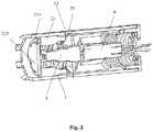
- FIG. 3is a view showing the inflating/deflating device shown in FIG. 1 in a pressurized state
- FIG. 4is a view showing the inflating/deflating device shown in FIG. 1 in a state of completion of air charging;
- FIG. 5is a view showing the inflating/deflating device shown in FIG. 1 in an air discharging state
- FIGS. 6A and 6Bare schematic views showing a protective clothing equipped with the inflating/deflating device shown in FIG. 1 ;
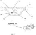
- FIG. 7is a sectional view showing a part of the clothing in FIG. 6A and FIG. 6B .
- upstream or upstream directionrefers to the direction from which the air originates when the inflating/deflating device is in an air-charging-operation state
- downstream or downstream directionrefers to the direction in which the air flows when the inflating/deflating device is in the air-charging-operation state
- FIG. 1is an exploded perspective view showing an inflating/deflating device according to a preferred embodiment of the present invention.
- the air inflating/deflating device 100comprises an outer cylinder 1 and an inner cylinder 2 slidably installed in the outer cylinder 1 .
- the inner cylinder 2is divided into two portions, i.e., a blade accommodation portion 21 and a motor accommodation portion 22 .
- a valve 23is provided on the downstream end of the blade accommodation portion 21 of the inner cylinder.
- a blade 3which is preferably multi-stage blade, is provided so as to pressurize the intake air to a higher pressure
- a motor 4which is preferably a reversible motor that is capable of rotating in both directions
- An end cap 6is further provided on the upstream end of the outer cylinder 1 , for example, by being screwed to the outer cylinder 1 , and holes are provided on the end cap 6 to allow the electric wires of the motor 4 to pass through and to allow air to be taken in while to block larger foreign substance.
- a biasing spring 5is provided between the inner cylinder 2 , specifically, the upstream end of the motor accommodating portion 22 of the inner cylinder 2 , and the end cover 6 , and biases the inner cylinder 2 in a downstream direction.
- the outer cylinder 1is open at its downstream end, and the inner cylinder 2 may be provided with a plurality of holes 24 in the end surface of its upstream end to allow air to pass through.
- the outer cylinder 1is provided with a plurality of holes 11 which are for example square holes on its peripheral wall.
- the inner cylinder 1is also provided with a plurality of holes 25 on its peripheral wall that are corresponding to and of for example the same shape as the holes 11 on the outer cylinder.
- the holes 11 and 25are provided at the same interval, and preferably, both provided at equal intervals around the circumferential direction.
- valve 23At the downstream end of the inner cylinder 2 a valve 23 is provided, the valve 23 , for example, is of diaphragm type.
- the valve 23comprises a valve body 232 and a leg 231 which is extending from a circumferential position of the valve body 232 and with which the valve 23 is fixed to the end surface of the downstream end of the inner tube 2 .
- a plurality of legsare provided in the circumferential direction (three are shown in the figure).
- a guide slot 12is provided at a substantially intermediate position of the outer cylinder 1 .
- more than one guide slot 12is provided, for example, two, three or more guide slots 12 that are evenly spaced apart in the circumferential direction are provided.
- a corresponding pin hole 26is provided at a corresponding position of the inner cylinder 2 to receive a guide pin (not shown).
- the inner cylinder 2is inserted into the outer cylinder 1 , and the guide pin is inserted into the pin hole 26 through the guide slot 12 and fixed to the inner cylinder 2 .
- the inner cylinder 2can thereby slide inside the outer cylinder 1 under the guidance of the guide slot 12 .
- the guide slot 12is preferably arranged to be inclined with respect to a longitudinal axis of the outer cylinder 1 and may have a certain curvature. Therefore, during the sliding process of the inner cylinder 2 along the guide slot 12 , the inner cylinder 2 carries out not only translational movements along the longitudinal axis of the outer cylinder 1 but also rotational movements about the longitudinal axis.
- Each end of the guide slot 12respectively constitutes a stop position of the inner cylinder 2 .
- the inner cylinder 2is in a downstream position, and the hole 25 in the circumferential direction thereof and the hole 11 in the circumferential direction of the outer cylinder 1 are aligned with each other, while when the guide pin is at the upstream end of the guide slot 12 , the inner cylinder 2 is in an upstream position, and the hole 25 of the inner cylinder 2 are not aligned with the hole 11 of the outer cylinder 1 and closed by the cylinder wall of the latter.
- a spring 5is provided between the upstream end of the inner cylinder 2 and the end cap 6 at the upstream end of the outer cylinder 1 to bias the inner cylinder 2 toward the downstream direction, that is, toward the downstream position.
- the blade 3adopts a three-stage blade, and comprises a first diameter blade 31 , a second diameter blade 32 , and a third diameter blade 33 in a direction from upstream to downstream, the first diameter blade 31 has a diameter being larger than that of the second diameter blade 32 , and the diameter of the second diameter blade 32 is larger than that of the third diameter blade 33 , making the air to be pressurized stage by stage.
- the above-mentioned three-stage bladeis merely exemplary, and more or fewer stages in the blade may be provided according to different needs to generate the required higher air pressure.
- the blade accommodating portion 21 of the inner cylinder 2comprises an inner cavity with varying diameters in which the second diameter blade 32 and the third diameter blade 33 of the blade 3 are accommodated.
- the dimensions of the inner cavitysubstantially correspond to those of the second diameter blade and the third diameter blade such that the inner cavity envelopes these two stages of the blade. This facilitates pressurizing the air to higher pressures.
- the motoris a reversible motor and wires of the motor are led out from the end cap 6 to be connected to a control circuit (not shown).
- the holes 25are formed on the peripheral wall of the motor accommodating portion 22 and at a longitudinal position substantially corresponding to the first diameter blade 31 .
- FIGS. 2 to 5the operation modes of the inflating/deflating device according a preferred embodiment of the present invention will be briefly described.
- the following descriptionis provided in the case that the inflating/deflating device is arranged in a protective clothing, but it should be appreciated that it can also be used in various target objects that require air charging and discharging, and the present invention is not limited hereto.
- the inner cylinder 2is biased to the downstream position, and the holes 25 of the inner cylinder 2 are aligned with the holes 11 of the outer cylinder 1 , then the motor 4 is energized, and thus air is taken in from the end cap 6 and pressurized by the third-stage blade 3 , so as to be charged into a target object.
- a part of the air pressurized by the first diameter blade 31is injected into the target object, such as an inner cavity of a protective clothing, through the aligned holes 25 and 11 , and another part of the pressurized air is continued to be pressurized through the second diameter blade 32 and the third diameter blade 33 to force the valve 23 open, and so as to be charged into the protective clothing from the downstream end of the inner cylinder 2 .
- the acting force of the air in the protective clothingincreases as the pressure thereof increases, thereby pushing the valve body 232 of the valve 23 toward the end surface of the downstream end of the inner cylinder 2 and simultaneously moving the inner tube 2 in the upstream direction against the bias force of the spring 5 .
- the inner cylinder 2moves and rotates under the guidance of the guide slot 12 until the guide pin abuts against the upstream end of the guide slot 12 , and then the hole 25 of the inner cylinder 2 is closed by the cylinder wall of the outer cylinder 1 , causing the air is stopped to be supplied into the target object through the holes 25 and 11 .
- the airis further pressurized by the second diameter blade 32 and the third diameter blade 33 , and when the air has a pressure greater than that in the protective clothing, it forces the valve 23 open and then continues to be charged into the protective clothing through the downstream end of the inner cylinder 2 , as shown in FIG. 3 .
- a sensor 254such as a pressure sensor, is provided to turn off the power supply to the motor 4 when this state is reached.
- a stop section 121 extending in the circumferential directionis provided at the upstream end of the guide slot 12 .
- the guide pinfalls into the stop section 121 as a result of a rotation inertia of the inner cylinder 2 along the inclined guide slot 12 .
- the motor and the thus the blade 3rotate in a direction opposite to that for air charging.
- the inner cylinder 2also rotates with the blade 3 , thereby causing the guide pin escape out of the stop section 121 , and under the suction effect of the blades 3 and the elastic effect of the spring 5 , the inner cylinder 2 moves toward the downstream direction, at the same time, the guide pin sliding along the guide slot 12 , rendering the holes 11 and 25 to gradually overlap, and then an air discharging position in which the holes 11 and 25 are completely aligned shown in FIG. 5 being reached, thereby all of the air in the protective clothing can be rapidly discharged.
- another sensoris further provided to automatically stop the operation of the motor 4 after the air is discharged.
- motor 4can be turned off by manual operation.
- the aircan be pressurized to a higher pressure and rapidly released and discharged as desired.
- FIGS. 6A and 6Ba protective clothing 200 employing the inflating/deflating device in the above embodiment is described with reference to FIGS. 6A and 6B .
- the protective clothing 200is made of a gas-impermeable material and constituted of an outer layer 251 and an inner layer 252 with a closed cavity 253 formed therebetween, air is able to be charged into this cavity 253 to bring the protective clothing into an inflated state.
- An air chamber 230 in which the inflating/deflating device 100 can be arrangedis, for example, formed on the shoulder of the protective clothing 200 and is sealed from the cavity.
- the present inventionis not limited thereto, and only one air chamber 230 and one inflating/deflating device 100 may be provided, or multiple air chambers and air charging and discharging devices may be provided.
- the air chamber 230is connected to a plurality of air pipes 210 which extend into the cavity of the protective clothing, and in the wall of the air pipes, a plurality of air holes 240 are formed.
- air from outsidecan be taken in the air chamber 230 and is pressured by the inflating/deflating device.
- the pressurized aircan be forced to flow through the air pipes 210 and into the cavity of the protective clothing, thereby the cavity being inflated; and in particular, in the case of air discharging operation, the air is likewise smoothly evacuated from the cavity of the protective clothing through the air holes 240 of the air pipes 210 .
- Ventilation structuresare provided at several positions of the protective clothing, for example, hollow rivets 220 are arranged by penetrating the outer and inner layers of the protective clothing to form a ventilation hole 221 passing through the outer layer and the inner layer, thereby ventilation of the protective clothing is possible without air leak therefrom, avoiding discomfort for those wearing the protective clothing.
- the cavity of the protective clothingmay be additionally filled with a warm material such as duck down.
- a warm materialsuch as duck down.
- the provision of the hollow rivet 220is beneficial to prevent the warm material from being displaced in the cavity.
- a controller ( FIG. 7 ) and/or a switch for controlling the inflating/deflating device 100may be provided at a position such as a cuff or the like for easy manual manipulation.
- the protective clothingis shown above as an upper outer garment, a pants-type protective clothing is also possible.
- the inflating/deflating device 100may be provided at a position such as a trouser leg.
- the protective clothing according to the present inventionmay be provided with a sensing mechanism 254 , which may include, for example, an acceleration sensor, a proximity sensor, a gyroscope, an image sensor, etc., in order to sense the wearer's speed, acceleration, and distance from the wearer to a closest obstacle, or to sense an outside object or person that is rapidly approaching the wearer of the protective clothing, and to trigger the inflating/deflating device to rapidly inflate the protective clothing and protect the wearer's personal safety when one or more of the speed, acceleration, and distance reaches a predetermined threshold that may be set based on the probability of a collision between the wearer and the obstacle.
- the protective clothingcan be manually deflated, so that the protective clothing is worn like ordinary clothing to avoid hindering the wearer's movement.
- the wearer of the protective clothingmay actively inflate or partially inflate the protective clothing in order to protect against danger in advance.
- the protective clothingAfter taking off the protective clothing, since the protective clothing can be easily inflated and deflated, it can be folded and stored like ordinary clothing, which improves the convenience of storage. In addition, the protective clothing according to the present invention can be used repeatedly for many times, reducing the cost for use.
Landscapes
- Engineering & Computer Science (AREA)
- Mechanical Engineering (AREA)
- General Engineering & Computer Science (AREA)
- Textile Engineering (AREA)
- Health & Medical Sciences (AREA)
- General Health & Medical Sciences (AREA)
- Physical Education & Sports Medicine (AREA)
- Professional, Industrial, Or Sporting Protective Garments (AREA)
- Respiratory Apparatuses And Protective Means (AREA)
- Structures Of Non-Positive Displacement Pumps (AREA)
Abstract
Description
Claims (18)
Applications Claiming Priority (1)
| Application Number | Priority Date | Filing Date | Title |
|---|---|---|---|
| PCT/CN2017/105381WO2019071387A1 (en) | 2017-10-09 | 2017-10-09 | Rapid inflating and discharging device for protective suit and intelligent multi-purpose protective suit comprising same |
Publications (2)
| Publication Number | Publication Date |
|---|---|
| US20200237033A1 US20200237033A1 (en) | 2020-07-30 |
| US11470890B2true US11470890B2 (en) | 2022-10-18 |
Family
ID=66100191
Family Applications (1)
| Application Number | Title | Priority Date | Filing Date |
|---|---|---|---|
| US16/753,078Active2038-09-17US11470890B2 (en) | 2017-10-09 | 2017-10-09 | Rapid inflating and discharging device for protective suit and intelligent multi-purpose protective suit comprising same |
Country Status (8)
| Country | Link |
|---|---|
| US (1) | US11470890B2 (en) |
| EP (1) | EP3696422B1 (en) |
| JP (1) | JP7033207B2 (en) |
| KR (1) | KR20200066625A (en) |
| AU (1) | AU2017435532A1 (en) |
| CA (1) | CA3078543A1 (en) |
| RU (1) | RU2741524C1 (en) |
| WO (1) | WO2019071387A1 (en) |
Families Citing this family (1)
| Publication number | Priority date | Publication date | Assignee | Title |
|---|---|---|---|---|
| US10743095B1 (en)* | 2019-03-21 | 2020-08-11 | Apple Inc. | Contextual audio system |
Citations (59)
| Publication number | Priority date | Publication date | Assignee | Title |
|---|---|---|---|---|
| US3468299A (en)* | 1967-12-20 | 1969-09-23 | Carl D Amato | Air-conditioned garment |
| EP0051254A1 (en) | 1980-10-27 | 1982-05-12 | Alfred Kroiss | Motor cycle suit |
| US5405370A (en)* | 1991-11-08 | 1995-04-11 | Irani; Feraidoon | Air blanket |
| US5500952A (en)* | 1994-10-28 | 1996-03-26 | Keyes; Marshall J. | Hip inflatable protection device |
| US5746442A (en)* | 1994-06-06 | 1998-05-05 | Hoyaukin; Peter | Safety apparel |
| CN2318434Y (en) | 1997-07-28 | 1999-05-12 | 华英工业股份有限公司 | Multi-stage booster fan |
| US6125478A (en)* | 1995-03-22 | 2000-10-03 | Merhav-A.A.P. Ltd. | Protection system for the rider of a non-enclosed vehicle |
| US6298487B1 (en)* | 2000-09-15 | 2001-10-09 | James W. Mayhew | Survival article of clothing |
| CN1429993A (en) | 2001-12-30 | 2003-07-16 | 王正宗 | Air valve device |
| US20050067816A1 (en)* | 2002-12-18 | 2005-03-31 | Buckman Robert F. | Method and apparatus for body impact protection |
| US20050079077A1 (en)* | 2003-06-09 | 2005-04-14 | Tsai Jing Hong | Reversible inflation system |
| CN2716552Y (en) | 2004-02-11 | 2005-08-10 | 宏竹实业股份有限公司 | Electric pump |
| US20060213523A1 (en)* | 2005-03-24 | 2006-09-28 | Stryker Corporation | Personal protection system |
| US20060222535A1 (en)* | 2005-03-04 | 2006-10-05 | Bestway (Usa) Inc., A Corporation Of Delaware | Built-in electrical inflating and deflating pump for inflatable product |
| US20070056500A1 (en)* | 2005-09-12 | 2007-03-15 | Beck Ralph F | Avalanche survival kit |
| US20080076309A1 (en)* | 2004-03-03 | 2008-03-27 | Parice Sandrin | Life-Saving Clothing |
| US20080282453A1 (en)* | 2005-10-26 | 2008-11-20 | Terese Alstin | System and Method for Protecting a Bodypart |
| US7774867B2 (en)* | 2007-01-31 | 2010-08-17 | Honda Motor Co., Ltd. | Airbag jacket for a vehicle rider |
| US20100247356A1 (en)* | 2009-03-26 | 2010-09-30 | Dongguan Tiger Point, Metal & Plastic Products Co. Ltd. | Air pump for air mattress |
| US20100247337A1 (en)* | 2009-03-26 | 2010-09-30 | Chun-Chung Tsai | Air pump for air mattress |
| WO2011148353A1 (en) | 2010-05-28 | 2011-12-01 | Freni Brembo S.P.A. | Protective garment with an airbag |
| US20120060267A1 (en)* | 2010-09-14 | 2012-03-15 | Arc'teryx Equipment Inc. | Airbag rescue system |
| US20120073035A1 (en)* | 2009-06-05 | 2012-03-29 | Alpinestars Research Srl | Airbag system for motorcycle drivers |
| US20120131718A1 (en)* | 2009-02-09 | 2012-05-31 | Prop Co. Ltd. | Airbag device for the body |
| CN102606496A (en) | 2012-03-06 | 2012-07-25 | 东莞市鹏科电子科技有限公司 | Air pump and opening and closing structure of air valve thereof |
| CN102961833A (en) | 2012-11-01 | 2013-03-13 | 浙江大学 | High-altitude protective suit |
| US20130312168A1 (en)* | 2011-02-03 | 2013-11-28 | Amatsia Raanan | Hip protector system and method for hip fracture prevention |
| US8595864B2 (en)* | 2007-03-30 | 2013-12-03 | Honda Motor Co., Ltd | Air bag jacket |
| US8720751B2 (en)* | 2012-10-15 | 2014-05-13 | Abdulreidha Abdulrasoul AlSaffar | Lifesaver backpack |
| US8851948B2 (en)* | 2011-12-13 | 2014-10-07 | Black Diamond Equipment, Ltd | Systems and methods for inflatable avalanche protection with reinflation |
| US20150173433A1 (en)* | 2012-06-26 | 2015-06-25 | Alpinestars Research Srl | Lining mounted inflatable protector and protective clothing assembly |
| US20150308454A1 (en)* | 2014-04-24 | 2015-10-29 | Anyun SHI | Push-button air pump |
| US20150374060A1 (en)* | 2013-03-04 | 2015-12-31 | Tate Technology, Llc | Balaclava hood system |
| US9289633B2 (en)* | 2011-12-13 | 2016-03-22 | Black Diamond Equipment, Ltd. | Systems and methods for inflatable avalanche protection |
| US20160174626A1 (en)* | 2013-08-06 | 2016-06-23 | Alpinestars Research Srl | Garment with an emergency device and associated emergency method |
| CN105756978A (en) | 2016-05-04 | 2016-07-13 | 杭州太普机械科技有限公司 | Portable inflation device |
| US20160215780A1 (en)* | 2013-10-18 | 2016-07-28 | Bestway Inflatables & Material Corp. | Built-in electric air pumps for inflating objects |
| US9427625B2 (en)* | 2014-07-18 | 2016-08-30 | Amer Sports Canada Inc. | Airbag rescue system and triggering device therefor |
| US9440133B2 (en)* | 2014-07-03 | 2016-09-13 | The North Face Apparel Corp. | Modular airbag system for personal protection |
| CN205912926U (en) | 2016-07-15 | 2017-02-01 | 北京大学深圳医院 | Clothes are fallen in old people's air defense with automatic charging function |
| US9637210B2 (en)* | 2014-10-16 | 2017-05-02 | Air Cruisers Company | Electric powered inflation system |
| US20170181482A1 (en)* | 2015-12-28 | 2017-06-29 | Ian A. Bruce | Emergency anti-hypothermia system and highly portable, inflatable emergency vest therefor |
| US20170202279A1 (en)* | 2014-07-22 | 2017-07-20 | Alpinestars Research Srl | Protective garment provided with an inflatable protective device and associated inflating method |
| US9752693B2 (en)* | 2012-08-03 | 2017-09-05 | Robert B. Chaffee | Self-sealing valve |
| US20170325521A1 (en)* | 2016-05-13 | 2017-11-16 | Toyota Motor Engineering & Manufacturing North America, Inc. | Wearable airbag |
| US20190106185A1 (en)* | 2017-10-05 | 2019-04-11 | Dakine, Inc. | Airbag compartment enclosure assembly |
| US20190166928A1 (en)* | 2016-08-01 | 2019-06-06 | Makita Corporation | Ventilation apparatus and a garment on which the ventilation apparatus can be mounted |
| US20190239578A1 (en)* | 2016-03-09 | 2019-08-08 | Sft Laboratory Co., Ltd. | Electric component mounting unit for air-conditioned garment, and air-conditioned garment |
| US10539941B2 (en)* | 2005-05-24 | 2020-01-21 | Deep Science, Llc | Energy dissipative cushioning elements |
| US10617895B2 (en)* | 2015-05-27 | 2020-04-14 | Nic Impex | Device for inflating multiple envelopes |
| US20200309152A1 (en)* | 2019-03-27 | 2020-10-01 | Arthur C Sanford | Special Personal Cooling Device Called the Breezy Belt |
| US20200359714A1 (en)* | 2017-12-15 | 2020-11-19 | Bemicron | Active breathing system |
| US20200359715A1 (en)* | 2018-01-25 | 2020-11-19 | Teijin Limited | Garment |
| US11058226B2 (en)* | 2016-12-08 | 2021-07-13 | Intex Marketing Ltd. | Recessed air pump |
| US20210329986A1 (en)* | 2018-12-05 | 2021-10-28 | Alpinestars Research S.p.A. | Garment comprising an inflatable protection device |
| US11167912B2 (en)* | 2017-09-13 | 2021-11-09 | The Procter & Gamble Company | Preform with valve anti-removal feature |
| US20210360993A1 (en)* | 2018-12-05 | 2021-11-25 | Alpinestars Research S.p.A. | Wearable airbag device |
| US20210368872A1 (en)* | 2020-05-29 | 2021-12-02 | Make Great Sales Limited | Wearable temperature control device |
| US20220001241A1 (en)* | 2020-07-02 | 2022-01-06 | Choprix Llc | Modular attachable airbag compartments for whole-body avalanche protection system |
Family Cites Families (7)
| Publication number | Priority date | Publication date | Assignee | Title |
|---|---|---|---|---|
| SU1509021A1 (en)* | 1969-03-18 | 1989-09-23 | С.К.Мамаев | Apparatus for protecting the man from traumas when falling |
| DE4301069A1 (en)* | 1993-01-16 | 1994-07-21 | Daimler Benz Ag | Fuel injection on a diesel engine |
| DE19522306B4 (en)* | 1994-06-24 | 2004-08-26 | Denso Corp., Kariya | High-pressure fuel supply pump |
| TW529685U (en)* | 2001-11-28 | 2003-04-21 | Jeng-Tzung Wang | Air valve device |
| CN201121600Y (en)* | 2007-09-14 | 2008-09-24 | 石安云 | Novel built-in manual-adjustment electric air pump |
| KR101248094B1 (en)* | 2011-02-28 | 2013-03-27 | 이화여자대학교 산학협력단 | Aeration smart wear changing silhouette for air string assembly |
| DE102014217560B3 (en)* | 2014-09-03 | 2015-11-12 | Continental Automotive Gmbh | Method and device for improving the combustion processes taking place in the cylinders of an internal combustion engine |
- 2017
- 2017-10-09KRKR1020207010107Apatent/KR20200066625A/ennot_activeAbandoned
- 2017-10-09RURU2020115395Apatent/RU2741524C1/enactive
- 2017-10-09CACA3078543Apatent/CA3078543A1/enactivePending
- 2017-10-09USUS16/753,078patent/US11470890B2/enactiveActive
- 2017-10-09AUAU2017435532Apatent/AU2017435532A1/ennot_activeAbandoned
- 2017-10-09JPJP2020540661Apatent/JP7033207B2/enactiveActive
- 2017-10-09WOPCT/CN2017/105381patent/WO2019071387A1/ennot_activeCeased
- 2017-10-09EPEP17928379.1Apatent/EP3696422B1/enactiveActive
Patent Citations (60)
| Publication number | Priority date | Publication date | Assignee | Title |
|---|---|---|---|---|
| US3468299A (en)* | 1967-12-20 | 1969-09-23 | Carl D Amato | Air-conditioned garment |
| EP0051254A1 (en) | 1980-10-27 | 1982-05-12 | Alfred Kroiss | Motor cycle suit |
| US5405370A (en)* | 1991-11-08 | 1995-04-11 | Irani; Feraidoon | Air blanket |
| US5746442A (en)* | 1994-06-06 | 1998-05-05 | Hoyaukin; Peter | Safety apparel |
| US5500952A (en)* | 1994-10-28 | 1996-03-26 | Keyes; Marshall J. | Hip inflatable protection device |
| US6125478A (en)* | 1995-03-22 | 2000-10-03 | Merhav-A.A.P. Ltd. | Protection system for the rider of a non-enclosed vehicle |
| CN2318434Y (en) | 1997-07-28 | 1999-05-12 | 华英工业股份有限公司 | Multi-stage booster fan |
| US6298487B1 (en)* | 2000-09-15 | 2001-10-09 | James W. Mayhew | Survival article of clothing |
| CN1429993A (en) | 2001-12-30 | 2003-07-16 | 王正宗 | Air valve device |
| US20050067816A1 (en)* | 2002-12-18 | 2005-03-31 | Buckman Robert F. | Method and apparatus for body impact protection |
| US20050079077A1 (en)* | 2003-06-09 | 2005-04-14 | Tsai Jing Hong | Reversible inflation system |
| CN2716552Y (en) | 2004-02-11 | 2005-08-10 | 宏竹实业股份有限公司 | Electric pump |
| US20080076309A1 (en)* | 2004-03-03 | 2008-03-27 | Parice Sandrin | Life-Saving Clothing |
| US20060222535A1 (en)* | 2005-03-04 | 2006-10-05 | Bestway (Usa) Inc., A Corporation Of Delaware | Built-in electrical inflating and deflating pump for inflatable product |
| US20060213523A1 (en)* | 2005-03-24 | 2006-09-28 | Stryker Corporation | Personal protection system |
| US10539941B2 (en)* | 2005-05-24 | 2020-01-21 | Deep Science, Llc | Energy dissipative cushioning elements |
| US20070056500A1 (en)* | 2005-09-12 | 2007-03-15 | Beck Ralph F | Avalanche survival kit |
| US20080282453A1 (en)* | 2005-10-26 | 2008-11-20 | Terese Alstin | System and Method for Protecting a Bodypart |
| US7774867B2 (en)* | 2007-01-31 | 2010-08-17 | Honda Motor Co., Ltd. | Airbag jacket for a vehicle rider |
| US8595864B2 (en)* | 2007-03-30 | 2013-12-03 | Honda Motor Co., Ltd | Air bag jacket |
| US20120131718A1 (en)* | 2009-02-09 | 2012-05-31 | Prop Co. Ltd. | Airbag device for the body |
| US20100247356A1 (en)* | 2009-03-26 | 2010-09-30 | Dongguan Tiger Point, Metal & Plastic Products Co. Ltd. | Air pump for air mattress |
| US20100247337A1 (en)* | 2009-03-26 | 2010-09-30 | Chun-Chung Tsai | Air pump for air mattress |
| US20120073035A1 (en)* | 2009-06-05 | 2012-03-29 | Alpinestars Research Srl | Airbag system for motorcycle drivers |
| WO2011148353A1 (en) | 2010-05-28 | 2011-12-01 | Freni Brembo S.P.A. | Protective garment with an airbag |
| US20120060267A1 (en)* | 2010-09-14 | 2012-03-15 | Arc'teryx Equipment Inc. | Airbag rescue system |
| US20130312168A1 (en)* | 2011-02-03 | 2013-11-28 | Amatsia Raanan | Hip protector system and method for hip fracture prevention |
| US9289633B2 (en)* | 2011-12-13 | 2016-03-22 | Black Diamond Equipment, Ltd. | Systems and methods for inflatable avalanche protection |
| US8851948B2 (en)* | 2011-12-13 | 2014-10-07 | Black Diamond Equipment, Ltd | Systems and methods for inflatable avalanche protection with reinflation |
| CN102606496A (en) | 2012-03-06 | 2012-07-25 | 东莞市鹏科电子科技有限公司 | Air pump and opening and closing structure of air valve thereof |
| US20150173433A1 (en)* | 2012-06-26 | 2015-06-25 | Alpinestars Research Srl | Lining mounted inflatable protector and protective clothing assembly |
| US9752693B2 (en)* | 2012-08-03 | 2017-09-05 | Robert B. Chaffee | Self-sealing valve |
| US8720751B2 (en)* | 2012-10-15 | 2014-05-13 | Abdulreidha Abdulrasoul AlSaffar | Lifesaver backpack |
| CN102961833A (en) | 2012-11-01 | 2013-03-13 | 浙江大学 | High-altitude protective suit |
| US20150374060A1 (en)* | 2013-03-04 | 2015-12-31 | Tate Technology, Llc | Balaclava hood system |
| US20160174626A1 (en)* | 2013-08-06 | 2016-06-23 | Alpinestars Research Srl | Garment with an emergency device and associated emergency method |
| US20160215780A1 (en)* | 2013-10-18 | 2016-07-28 | Bestway Inflatables & Material Corp. | Built-in electric air pumps for inflating objects |
| US20150308454A1 (en)* | 2014-04-24 | 2015-10-29 | Anyun SHI | Push-button air pump |
| US9440133B2 (en)* | 2014-07-03 | 2016-09-13 | The North Face Apparel Corp. | Modular airbag system for personal protection |
| US9427625B2 (en)* | 2014-07-18 | 2016-08-30 | Amer Sports Canada Inc. | Airbag rescue system and triggering device therefor |
| US20170202279A1 (en)* | 2014-07-22 | 2017-07-20 | Alpinestars Research Srl | Protective garment provided with an inflatable protective device and associated inflating method |
| US9637210B2 (en)* | 2014-10-16 | 2017-05-02 | Air Cruisers Company | Electric powered inflation system |
| US10617895B2 (en)* | 2015-05-27 | 2020-04-14 | Nic Impex | Device for inflating multiple envelopes |
| US20170181482A1 (en)* | 2015-12-28 | 2017-06-29 | Ian A. Bruce | Emergency anti-hypothermia system and highly portable, inflatable emergency vest therefor |
| US20190239578A1 (en)* | 2016-03-09 | 2019-08-08 | Sft Laboratory Co., Ltd. | Electric component mounting unit for air-conditioned garment, and air-conditioned garment |
| CN105756978A (en) | 2016-05-04 | 2016-07-13 | 杭州太普机械科技有限公司 | Portable inflation device |
| US20170325521A1 (en)* | 2016-05-13 | 2017-11-16 | Toyota Motor Engineering & Manufacturing North America, Inc. | Wearable airbag |
| CN205912926U (en) | 2016-07-15 | 2017-02-01 | 北京大学深圳医院 | Clothes are fallen in old people's air defense with automatic charging function |
| US20190166928A1 (en)* | 2016-08-01 | 2019-06-06 | Makita Corporation | Ventilation apparatus and a garment on which the ventilation apparatus can be mounted |
| US11058226B2 (en)* | 2016-12-08 | 2021-07-13 | Intex Marketing Ltd. | Recessed air pump |
| US11167912B2 (en)* | 2017-09-13 | 2021-11-09 | The Procter & Gamble Company | Preform with valve anti-removal feature |
| US20190106185A1 (en)* | 2017-10-05 | 2019-04-11 | Dakine, Inc. | Airbag compartment enclosure assembly |
| US11034419B2 (en)* | 2017-10-05 | 2021-06-15 | Dakine IP Holdings LP | Airbag compartment enclosure assembly |
| US20200359714A1 (en)* | 2017-12-15 | 2020-11-19 | Bemicron | Active breathing system |
| US20200359715A1 (en)* | 2018-01-25 | 2020-11-19 | Teijin Limited | Garment |
| US20210329986A1 (en)* | 2018-12-05 | 2021-10-28 | Alpinestars Research S.p.A. | Garment comprising an inflatable protection device |
| US20210360993A1 (en)* | 2018-12-05 | 2021-11-25 | Alpinestars Research S.p.A. | Wearable airbag device |
| US20200309152A1 (en)* | 2019-03-27 | 2020-10-01 | Arthur C Sanford | Special Personal Cooling Device Called the Breezy Belt |
| US20210368872A1 (en)* | 2020-05-29 | 2021-12-02 | Make Great Sales Limited | Wearable temperature control device |
| US20220001241A1 (en)* | 2020-07-02 | 2022-01-06 | Choprix Llc | Modular attachable airbag compartments for whole-body avalanche protection system |
Non-Patent Citations (1)
| Title |
|---|
| Search Report issued in Int'l App. No. PCT/CN2017/105381 (dated 2018). |
Also Published As
| Publication number | Publication date |
|---|---|
| AU2017435532A1 (en) | 2020-04-09 |
| WO2019071387A1 (en) | 2019-04-18 |
| KR20200066625A (en) | 2020-06-10 |
| EP3696422A4 (en) | 2021-05-05 |
| EP3696422A1 (en) | 2020-08-19 |
| CA3078543A1 (en) | 2019-04-18 |
| US20200237033A1 (en) | 2020-07-30 |
| JP2021503570A (en) | 2021-02-12 |
| RU2741524C1 (en) | 2021-01-26 |
| EP3696422B1 (en) | 2023-12-06 |
| JP7033207B2 (en) | 2022-03-09 |
Similar Documents
| Publication | Publication Date | Title |
|---|---|---|
| EP2616147B1 (en) | Airbag rescue system | |
| ES2247452T3 (en) | AIRBAG | |
| EP2621297B1 (en) | Airbag suitable for head protection | |
| US8851948B2 (en) | Systems and methods for inflatable avalanche protection with reinflation | |
| US8851949B2 (en) | Systems and methods for inflatable avalanche protection with active deflation | |
| US9004116B2 (en) | Systems and methods for inflatable avalanche protection | |
| US20130149923A1 (en) | Systems and methods for inflatable avalanche protection | |
| US9675505B2 (en) | System and method for preventing fall-related injuries | |
| US11470890B2 (en) | Rapid inflating and discharging device for protective suit and intelligent multi-purpose protective suit comprising same | |
| CN110839982A (en) | Wearable old man prevents falling and hipbone portion protection device | |
| KR20140000900A (en) | Portable life security pack | |
| CN107023706B (en) | Mechanically actuated inflation valve actuation device | |
| JP3214415U (en) | Airbag mechanism | |
| EP2700433B1 (en) | Systems and methods for inflatable avalanche protection with reinflation | |
| EP2604318B1 (en) | Systems and methods for inflatable avalanche protection with active deflation. | |
| CN211721946U (en) | Air bag with built-in air source | |
| CN110169612B (en) | a safety garment | |
| US9364692B2 (en) | Inflatable lifesaving device | |
| GB2382121A (en) | Poppet valve for safety cushion | |
| CN205871985U (en) | A kind of elastic safety airbag structure | |
| CN207286481U (en) | A kind of high altitude escape clothing | |
| CN1548339A (en) | Disposable portable live-saving air bag for use in water | |
| CN209959429U (en) | Miniature air pump relief valve | |
| ES2603604B1 (en) | Cushion of falls for people | |
| WO2025012246A1 (en) | Protection device, use of the protection device and method of operating the protection device |
Legal Events
| Date | Code | Title | Description |
|---|---|---|---|
| AS | Assignment | Owner name:BEIJING MKS RESEARCH INSTITUTE, CHINA Free format text:ASSIGNMENT OF ASSIGNORS INTEREST;ASSIGNORS:SUN, YINGUI;ZHOU, HUI ELIZABETH;WANG, SHIGUO;AND OTHERS;REEL/FRAME:052295/0013 Effective date:20200330 | |
| FEPP | Fee payment procedure | Free format text:ENTITY STATUS SET TO UNDISCOUNTED (ORIGINAL EVENT CODE: BIG.); ENTITY STATUS OF PATENT OWNER: SMALL ENTITY | |
| FEPP | Fee payment procedure | Free format text:ENTITY STATUS SET TO SMALL (ORIGINAL EVENT CODE: SMAL); ENTITY STATUS OF PATENT OWNER: SMALL ENTITY | |
| STPP | Information on status: patent application and granting procedure in general | Free format text:APPLICATION DISPATCHED FROM PREEXAM, NOT YET DOCKETED | |
| STPP | Information on status: patent application and granting procedure in general | Free format text:DOCKETED NEW CASE - READY FOR EXAMINATION | |
| STPP | Information on status: patent application and granting procedure in general | Free format text:NON FINAL ACTION MAILED | |
| STPP | Information on status: patent application and granting procedure in general | Free format text:RESPONSE TO NON-FINAL OFFICE ACTION ENTERED AND FORWARDED TO EXAMINER | |
| STPP | Information on status: patent application and granting procedure in general | Free format text:NOTICE OF ALLOWANCE MAILED -- APPLICATION RECEIVED IN OFFICE OF PUBLICATIONS | |
| STPP | Information on status: patent application and granting procedure in general | Free format text:PUBLICATIONS -- ISSUE FEE PAYMENT VERIFIED | |
| STCF | Information on status: patent grant | Free format text:PATENTED CASE |