US11470825B2 - Apparatus and methods for controlling a habitat environment - Google Patents
Apparatus and methods for controlling a habitat environmentDownload PDFInfo
- Publication number
- US11470825B2 US11470825B2US16/573,419US201916573419AUS11470825B2US 11470825 B2US11470825 B2US 11470825B2US 201916573419 AUS201916573419 AUS 201916573419AUS 11470825 B2US11470825 B2US 11470825B2
- Authority
- US
- United States
- Prior art keywords
- habitat
- operating data
- main pump
- server
- bridge
- Prior art date
- Legal status (The legal status is an assumption and is not a legal conclusion. Google has not performed a legal analysis and makes no representation as to the accuracy of the status listed.)
- Active
Links
Images


Classifications
- A—HUMAN NECESSITIES
- A01—AGRICULTURE; FORESTRY; ANIMAL HUSBANDRY; HUNTING; TRAPPING; FISHING
- A01K—ANIMAL HUSBANDRY; AVICULTURE; APICULTURE; PISCICULTURE; FISHING; REARING OR BREEDING ANIMALS, NOT OTHERWISE PROVIDED FOR; NEW BREEDS OF ANIMALS
- A01K63/00—Receptacles for live fish, e.g. aquaria; Terraria
- A01K63/003—Aquaria; Terraria
- A—HUMAN NECESSITIES
- A01—AGRICULTURE; FORESTRY; ANIMAL HUSBANDRY; HUNTING; TRAPPING; FISHING
- A01K—ANIMAL HUSBANDRY; AVICULTURE; APICULTURE; PISCICULTURE; FISHING; REARING OR BREEDING ANIMALS, NOT OTHERWISE PROVIDED FOR; NEW BREEDS OF ANIMALS
- A01K63/00—Receptacles for live fish, e.g. aquaria; Terraria
- A01K63/02—Receptacles specially adapted for transporting live fish
- A—HUMAN NECESSITIES
- A01—AGRICULTURE; FORESTRY; ANIMAL HUSBANDRY; HUNTING; TRAPPING; FISHING
- A01K—ANIMAL HUSBANDRY; AVICULTURE; APICULTURE; PISCICULTURE; FISHING; REARING OR BREEDING ANIMALS, NOT OTHERWISE PROVIDED FOR; NEW BREEDS OF ANIMALS
- A01K63/00—Receptacles for live fish, e.g. aquaria; Terraria
- A01K63/06—Arrangements for heating or lighting in, or attached to, receptacles for live fish
- G—PHYSICS
- G05—CONTROLLING; REGULATING
- G05B—CONTROL OR REGULATING SYSTEMS IN GENERAL; FUNCTIONAL ELEMENTS OF SUCH SYSTEMS; MONITORING OR TESTING ARRANGEMENTS FOR SUCH SYSTEMS OR ELEMENTS
- G05B15/00—Systems controlled by a computer
- G05B15/02—Systems controlled by a computer electric
- G—PHYSICS
- G06—COMPUTING OR CALCULATING; COUNTING
- G06F—ELECTRIC DIGITAL DATA PROCESSING
- G06F3/00—Input arrangements for transferring data to be processed into a form capable of being handled by the computer; Output arrangements for transferring data from processing unit to output unit, e.g. interface arrangements
- G06F3/01—Input arrangements or combined input and output arrangements for interaction between user and computer
- G06F3/048—Interaction techniques based on graphical user interfaces [GUI]
- G06F3/0484—Interaction techniques based on graphical user interfaces [GUI] for the control of specific functions or operations, e.g. selecting or manipulating an object, an image or a displayed text element, setting a parameter value or selecting a range
- G06F3/04847—Interaction techniques to control parameter settings, e.g. interaction with sliders or dials
- H—ELECTRICITY
- H04—ELECTRIC COMMUNICATION TECHNIQUE
- H04L—TRANSMISSION OF DIGITAL INFORMATION, e.g. TELEGRAPHIC COMMUNICATION
- H04L12/00—Data switching networks
- H04L12/28—Data switching networks characterised by path configuration, e.g. LAN [Local Area Networks] or WAN [Wide Area Networks]
- H04L12/2803—Home automation networks
- H04L12/2816—Controlling appliance services of a home automation network by calling their functionalities
- H—ELECTRICITY
- H04—ELECTRIC COMMUNICATION TECHNIQUE
- H04L—TRANSMISSION OF DIGITAL INFORMATION, e.g. TELEGRAPHIC COMMUNICATION
- H04L12/00—Data switching networks
- H04L12/66—Arrangements for connecting between networks having differing types of switching systems, e.g. gateways
- H—ELECTRICITY
- H04—ELECTRIC COMMUNICATION TECHNIQUE
- H04L—TRANSMISSION OF DIGITAL INFORMATION, e.g. TELEGRAPHIC COMMUNICATION
- H04L67/00—Network arrangements or protocols for supporting network services or applications
- H04L67/01—Protocols
- H04L67/12—Protocols specially adapted for proprietary or special-purpose networking environments, e.g. medical networks, sensor networks, networks in vehicles or remote metering networks
- H04L67/125—Protocols specially adapted for proprietary or special-purpose networking environments, e.g. medical networks, sensor networks, networks in vehicles or remote metering networks involving control of end-device applications over a network
- G—PHYSICS
- G05—CONTROLLING; REGULATING
- G05B—CONTROL OR REGULATING SYSTEMS IN GENERAL; FUNCTIONAL ELEMENTS OF SUCH SYSTEMS; MONITORING OR TESTING ARRANGEMENTS FOR SUCH SYSTEMS OR ELEMENTS
- G05B2219/00—Program-control systems
- G05B2219/20—Pc systems
- G05B2219/25—Pc structure of the system
- G05B2219/25011—Domotique, I-O bus, home automation, building automation
- G—PHYSICS
- G05—CONTROLLING; REGULATING
- G05B—CONTROL OR REGULATING SYSTEMS IN GENERAL; FUNCTIONAL ELEMENTS OF SUCH SYSTEMS; MONITORING OR TESTING ARRANGEMENTS FOR SUCH SYSTEMS OR ELEMENTS
- G05B2219/00—Program-control systems
- G05B2219/30—Nc systems
- G05B2219/31—From computer integrated manufacturing till monitoring
- G05B2219/31434—Zone supervisor, collects error signals from, and diagnoses different zone
- H—ELECTRICITY
- H04—ELECTRIC COMMUNICATION TECHNIQUE
- H04L—TRANSMISSION OF DIGITAL INFORMATION, e.g. TELEGRAPHIC COMMUNICATION
- H04L41/00—Arrangements for maintenance, administration or management of data switching networks, e.g. of packet switching networks
- H04L41/22—Arrangements for maintenance, administration or management of data switching networks, e.g. of packet switching networks comprising specially adapted graphical user interfaces [GUI]
- H—ELECTRICITY
- H04—ELECTRIC COMMUNICATION TECHNIQUE
- H04L—TRANSMISSION OF DIGITAL INFORMATION, e.g. TELEGRAPHIC COMMUNICATION
- H04L69/00—Network arrangements, protocols or services independent of the application payload and not provided for in the other groups of this subclass
- H04L69/26—Special purpose or proprietary protocols or architectures
- Y—GENERAL TAGGING OF NEW TECHNOLOGICAL DEVELOPMENTS; GENERAL TAGGING OF CROSS-SECTIONAL TECHNOLOGIES SPANNING OVER SEVERAL SECTIONS OF THE IPC; TECHNICAL SUBJECTS COVERED BY FORMER USPC CROSS-REFERENCE ART COLLECTIONS [XRACs] AND DIGESTS
- Y02—TECHNOLOGIES OR APPLICATIONS FOR MITIGATION OR ADAPTATION AGAINST CLIMATE CHANGE
- Y02A—TECHNOLOGIES FOR ADAPTATION TO CLIMATE CHANGE
- Y02A40/00—Adaptation technologies in agriculture, forestry, livestock or agroalimentary production
- Y02A40/80—Adaptation technologies in agriculture, forestry, livestock or agroalimentary production in fisheries management
- Y02A40/81—Aquaculture, e.g. of fish
- Y—GENERAL TAGGING OF NEW TECHNOLOGICAL DEVELOPMENTS; GENERAL TAGGING OF CROSS-SECTIONAL TECHNOLOGIES SPANNING OVER SEVERAL SECTIONS OF THE IPC; TECHNICAL SUBJECTS COVERED BY FORMER USPC CROSS-REFERENCE ART COLLECTIONS [XRACs] AND DIGESTS
- Y04—INFORMATION OR COMMUNICATION TECHNOLOGIES HAVING AN IMPACT ON OTHER TECHNOLOGY AREAS
- Y04S—SYSTEMS INTEGRATING TECHNOLOGIES RELATED TO POWER NETWORK OPERATION, COMMUNICATION OR INFORMATION TECHNOLOGIES FOR IMPROVING THE ELECTRICAL POWER GENERATION, TRANSMISSION, DISTRIBUTION, MANAGEMENT OR USAGE, i.e. SMART GRIDS
- Y04S20/00—Management or operation of end-user stationary applications or the last stages of power distribution; Controlling, monitoring or operating thereof
- Y04S20/20—End-user application control systems
- Y04S20/242—Home appliances
Definitions
- the present inventionis directed to a habitat, components associated with the habitat, and controlling the various components associated with the habitat.
- Habitatstypically include a controlled environment, such as rooms or containers, that houses organisms, such as fish, invertebrates, amphibians, mammals, reptiles, plants, bacteria, or any combination thereof. These habitats require a high amount of care which includes maintaining specific environmental conditions, such as temperature, humidity, lighting type, lighting amount, salinity, pH, and flow control of air or water inside the habitat may need to be regulated depending on the organism living therein.
- the environmental conditionsmay be controlled by devices such as heaters, pumps, filters, fans, lighting systems, etc. While the combined effects of these devices are extremely important, the devices typically act independently of each other.
- a system for controlling a habitatincludes a server, a bridge, and a habitat component.
- the serverincludes a database containing information associated with a habitat component.
- the serveralso includes a communication interface for transmitting operating data for the habitat component.
- the bridgehas a first communication unit configured to communicate with the server communication interface and transmit the operating data received from the server to the habitat component.
- the habitat componenthas a second communication unit for receiving operating data from the bridge.
- a system for controlling an aquatic habitatincludes a bridge and a pump.
- the bridgehas a first communication unit configured to receive operating data from a user and transmit the received operating data to a component associated with a habitat.
- the pumpis associated with the habitat and includes a second communication unit for receiving operating data from the bridge.
- the pumpalso includes a microprocessor for converting the operating data received from the bridge to produce an output to control the pump.
- a method of controlling a habitatincludes inputting environmental information associated with a habitat to a user interface.
- the environmental informationis transmitted from a user interface to a server.
- Operating datais prepared related to a first component and a second component associated with the habitat.
- the operating data for the first and second componentsis transmitted from the server to a bridge associated with the habitat.
- the operating data related to the first componentis transmitted from the bridge to the first component.
- Operating data related to the second componentis transferred from the bridge to the second component.
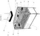
- FIG. 1is a perspective view of an aquatic habitat according to an exemplary embodiment of the invention.
- FIG. 2is a sectional schematic view of the pump assembly of the aquatic habitat of FIG. 1 according to an exemplary embodiment of the invention.
- FIG. 3is a sectional schematic view of the illumination assembly of the aquatic habitat of FIG. 1 according to an exemplary embodiment of the invention.
- FIG. 4is a schematic view of a habitat control system according to an exemplary embodiment of the invention.
- FIG. 5is a schematic view of a habitat control system according to an alternative exemplary embodiment of the invention.
- FIG. 1depicts an aquatic habitat 10 that utilizes the exemplary system and methods described herein. Other embodiments may be used in connection with the growth and support of any type of organism habitat including terrariums, green houses, nurseries, Petri dishes, etc.
- the habitat 10has a pair of side walls 12 , a pair of end walls 14 connected to the side walls 12 , a bottom 16 , and an open top 18 . Though depicted as having a standard rectangular shape, the habitat 10 may have a variety of sizes, shapes, and configurations and include any number of walls.
- the habitat 10may be made from a variety of materials, including glass or acrylic.
- the habitat 10includes a set of pumps 20 .
- a single pump 20is associated with each of the side walls 12 and end walls 14 .
- the pumps 20may vary in number, size, type, and operating characteristic.
- the pumps 20are magnetically coupled pumps such as disclosed in U.S. Pat. No.
- the pumps 20have a dry-side housing 22 and a wet-side housing 24 .
- the housings 22 , 24may be made from any suitable material, such as a polymer material formed via a molding or extrusion process.
- the dry-side housing 22includes a motor 26 connected to a magnet 28 .
- the motor 26may be electric, hydraulic, pneumatic, etc. In an exemplary embodiment, the motor 26 is a variable speed electric motor operating on either AC or DC.
- the magnet 28may be a circular disc having at least one pair of magnetic poles N and S.
- the poles N, Smay be arrayed in a radial pattern around the magnet 28 .
- the magnet 28may be made from a variety of magnetic materials including neodymium or other high performance magnetic materials. It should be understood that the magnet 28 may be configured differently, e.g. as an elongated bar or bars.
- the wet-side housing 24includes a magnet 30 connected via a shaft to a blade 32 .
- the blade 32may be an impeller or propeller type.
- the wet-side housing 24may be placed in the habitat 10 and magnetically coupled to the dry-side housing 22 located outside of the habitat 10 .
- the magnetic attraction between the magnets 28 , 30should be sufficiently strong so that the wet-side housing 24 is held in place in the habitat 10 with enough force to prevent the wet-side housing 24 from being dislodged due to liquid circulation or slight contact.
- the net magnetic attraction between the dry-side housing 22 and the wet-side housing 24may be at least 1.0 pound; however, this may vary depending on the size of the pump 20 and the operating environment.
- a variety of frictional elements or cooperating projections and depressionsmay be included on either of the housings 22 , 24 or the habitat 10 .
- additional mechanical and/or chemical holding meanscan be included to attach the housings 22 , 24 to the habitat 10 .
- the motor 26is connected, either directly or indirectly, to a driver 34 , a power supply 36 , and a communication unit 38 a .
- the power supply 36 and the communication unit 38 aare connected to a driver 34 via electrical connections 37 .
- the driver 34is also electrically connected to the motor 26 .
- the term “driver” as used hereinmay mean any type or combination of driver, controller, or microcontroller as well as any additional hardware or software components associated with controlling the operation of motor 26 .
- the power supply 36is DC battery powered, though AC outlet power may also be used.
- the driver 34varies the amount of power supplied to the motor 26 to control the rotational speed of the shaft 21 .
- the dry-side magnet 28is magnetically coupled to the wet-side magnet 30 which is connected via the shaft 25 to the blade 32 .
- the driver 34varies the amount and direction of fluid flow through the pumps 20 . This creates different effects as described in further detail below.
- the communication unit 38 amay be placed on the inside or outside of the dry-side housing 22 .
- the communication unit 38 amay be a wireless communication module, such as a Wi-Fi module or a radio module.
- the communication unit 38 areceives information and operating data from a source. The operating data may be processed by a microprocessor to control the pump 20 .
- the microprocessormay be part of the communication unit 38 a , part of the driver 34 , or a part of a separate, but electrically connected circuit. For example, the microprocessor may relay commands to the driver 34 .
- the communication unit 38 amay communicate with other components in the habitat 10 and/or a bridge 68 , as shown in FIG. 4 and described in greater detail below.
- the communication unit 38 amay also communicate with a local user interface. While the communication unit 38 a , the driver 34 , and the motor 26 are depicted in FIG. 2 as separate units, they may be consolidated into a single unit or any combination or variation thereof.
- a lighting unit 40can be suspended or otherwise mounted or positioned above the habitat 10 .
- the lighting unit 40includes a housing 42 having a top 44 and a transparent bottom 46 .
- the interior of the housing 42is shown containing a plurality of light emitters 48 although only a single light emitter may be used.
- a suspension assembly 49suspends the lighting unit 40 above the habitat 10 .
- the suspension assembly 49may include supports, brackets, posts, struts, legs, clips, or additional mechanical components which attach the lighting unit 40 to a ceiling, wall, or to a component of the habitat 10 , such as the side walls 12 , end walls 14 , bottom 16 , or top 18 .
- the light emitters 48may be capable of emitting light in a variety of colors and at various intensities.
- the light emitters 48may be light emitting diodes (LEDs), for example organic or non-organic LEDs.
- the light emitters 48are connected to a driver 50 or other similar control circuit.
- the driver 50is connected to a power supply 52 .
- a communication unit 38 bmay be connected to the driver 50 as well as to various other components of the lighting unit 40 .
- the power supply 52may be an AC source, such as a standard outlet, or a DC source, such as a battery or solar power.
- the power supply 52 and the communication unit 38 bare electrically connected to the driver 50 , and the driver 50 is electrically connected to the light emitters 48 . While the communication unit 38 b , driver 50 , and power supply 52 are depicted in FIG. 3 as separate units, they may be combined into a single unit or any combination or variation thereof.
- the driver 50provides on/off capability and also adjusts the amount of power supplied to each light emitter 48 or to a group of light emitters 48 so that the color and intensity of the emitted light can be varied to create different effects. If the light emitters 48 emit different color light, certain emitters 48 may be activated and others deactivated to control the light color output. In an exemplary embodiment, groups of light emitters 48 will have a range of wavelengths that is different or only slightly overlaps with other groups of light emitters 48 . For example, light emitters 48 may be separated into different color groups of white, red, green, blue, and royal blue. The wavelength of the light emitters 48 of each group may be varied to produce different shades and intensities of each color. Each color group may be on a single channel, so that the light emitters 48 are group controlled by the driver 50 as opposed to individually controlled.
- FIG. 3shows a single group of light emitters 48 .
- Multiple groups, comprising different amounts, sizes, and types of light emitters 48may be contained in the housing 42 .
- Each group of light emitters 48may have a dedicated driver 50 or multiple groups of light emitters 48 may be controlled by a single driver 50 .
- the communication unit 38 bis similar to communication unit 38 a described above.
- the communication unit 38 bmay be a wireless communication module, such as a Wi-Fi module, a radio module, or a combination of both.
- the communications units 38 a , 38is not necessarily wireless.
- the communication unit 38 breceives operating data.
- the operating datamay be processed by a microprocessor to control the lighting unit 40 .
- the microprocessormay be part of the communication unit 38 b , part of the driver 50 , or a part of a separate, but electrically connected circuit.
- the microprocessormay relay commands to the driver 50 .
- the communication unit 38 bmay also communicate with other components of the habitat 10 and the bridge 68 as described in greater detail below.
- the received operating datamay instruct the driver 50 to vary or modify power supplied to the light emitters 48 to produce different lighting effects. Some of these effects are discussed in greater detail below, but it should be noted that a wide variety of lighting effects may be achieved.
- each componentmay contain a corresponding driver, power source, communication unit, microprocessor, or any combination thereof.
- the filter 54may be a mechanical, chemical, or biological-type filter. As with the pumps 20 , more than one filter 54 , heating/cooling unit 56 , etc. may be used depending on the requirements of the habitat 10 .
- various exemplary embodimentsmay utilize sensors to monitor the habitat 10 and additional components for altering and controlling the environment. Sensors may monitor, for example, temperature at specific points in the habitat, including air and water temperature, water level, air and water flow, pH, salinity, moisture level, and humidity. Similarly, components to alter and control the environmental conditions properties, such as heaters, fans, pH adjusters, humidifiers, and water changers or watering systems may be monitored and controlled. Other sensors and components may be incorporated as will be understood by one of ordinary skill in the art.
- FIG. 4depicts a schematic of an exemplary system including a server 58 .
- the server 58may be a centralized server, or it may be information stored across a network, or other devices.
- the server 58includes a database 60 for storing information related to a user, the habitat 10 , and to different components associated with that habitat 10 .
- the server 58may have software, such as a computer program or a plurality of computer programs, for receiving, organizing, and storing the information related to the habitat 10 .
- the server 58also includes a communication interface 62 .
- the communication interface 62is capable of communicating with a user interface 66 and a bridge 68 .
- the user interface 66may be a software program for example a computer program, web application, web form, java application, mobile application, or other suitable program running on a computer, smart phone, remote, or other suitable electronic device.
- Various applications and software associated with individual devices for allowing the user to send and/or receive information and commands to the server 58 via user interface 66will be understood by one of ordinary skill in the art upon viewing this disclosure.
- the user interface 66may be separate from the server 58 , for example stored on a user's electronic device.
- the user interface 66may also be store, hosted, or otherwise associated with the server 58 .
- the user interface 66allows a user to convey and receive various information relating to the habitat 10 and its components, as well as provide operating data to the components of the habitat 10 .
- a userinputs information about the habitat 10 , for example the shape of the habitat 10 as well as information relating to the contents of the habitat 10 .
- a useralso inputs information relating to the type and number of components associated with the habitat. For example, with the habitat 10 shown in FIG. 1 , a user enters that there are four pumps 20 , and specifies the identification, location and type of each pump 20 . The user can also enter the type of lighting unit 40 , filter 54 , heating/cooling unit 56 , and any other components.
- the information about the habitat 10 and each componentis entered into the user interface 66 , for example it may be typed into a field or selected from a list or menu.
- the “user”may be the owner of the aquarium, a technician, or any other type of operator and is not limited to a specific or single person.
- the userenters information relating to the control of the components. For example, the user can enter information controlling the speed of individual pumps 20 to create different operational modes. Operational modes may be created by the user or may be selected from a predetermined list. The list may be generated automatically, for example by the server 58 or user interface 66 , based on the number and type of components entered into the system. Automatically generated operational modes may also be based on the specifics of the habitat 10 . Examples of operational modes that may be associated with an aquatic habitat include:
- Constant Speed Modeumps 20 run continuously at a constant speed which can be set by the user;
- the user interface 66allows a user to select different operational modes for individual pumps 20 , or a general operating mode for the entire habitat 10 .
- the user interface 66may also allow a user to select different operational modes for different times.
- the usermay enter commands instructing the lighting unit 40 to provide different color and intensity of light over a certain time interval, for example, to mimic a night-and-day cycle or to associate different lighting effects with the pump 20 operating modes described above. Utilizing a combination of these effects, a user can establish a profile for the individual components or the habitat 10 as a whole over a specific time period, for example a day, week, month, or year.
- the programming of componentsmay also include, but is not limited to, real time or prescheduled control of various components including: setting the feed mode speed of pumps, changing flow modes of the pumps throughout the day; changing speeds of the pumps throughout the day; and turning on and off components throughout the day.
- the user interface 66can allow the user to enter commands controlling any other sensors or components associated with the habitat 10 .
- the information and commands entered into the user interface 66are associated with an individual user profile saved in the database 60 .
- the informationmay be organized or compiled by the server 58 , for example through data integration techniques for combining and organizing multiple data sources, to be translated into different operating data forms as required by the system and the components.
- the operating datais then transmitted to a bridge 68 associated with the respective habitat 10 .
- the bridgeis capable of connecting the network formed by the habitat components to the server 58 .
- the bridge 68may also be capable of performing protocol conversion of the data.
- the datamay be coded according to the individual component or components the data is associated with.
- the operating datamay be transmitted as single packet. For example, operating data associated with multiple components may be sent in a single transmission to the bridge 68 .
- the bridge 68may be configured to recognize and sort operating data for each individual component and transmit the appropriate data to the appropriate component.
- the bridge 68may also transmit the entire packet of operating data to all components, and the components may be configured to determine which portion of the operating data to implement.
- the server 58may transmit operating data associated with different components in separate, individual transmissions. The bridge 68 may then pass the operating data to the appropriate component.
- the bridge 68may have various hardware and software to perform the operations described herein.
- FIG. 4shows the server 58 in communication with the user interface 66 and the bridge 68 through an Internet connection 64 .
- the server 58may be connected to multiple user interfaces 66 and multiple bridges 68 associated with different habitats 10 .
- the bridge 68may be positioned at the habitat 10 or remote from the habitat 10 .
- the bridge 68is connected to the Internet 64 either wirelessly or through a hard line connection.
- the bridge 68may have a housing which includes a communication unit 38 c .
- the bridge 68may also have a USB port to connect to a computer for setup and firmware updating or restoring, though these functions may also be performed through a wireless connection.
- Various other componentssuch as a power supply, display screen, indicators, Ethernet input, wireless card, microprocessor, etc. may be associated with the bridge 68 .
- the bridge 68has controls, such as button, switches, etc., for set up, and an indicator, such as LEDs, a screen, etc., to allow a user to monitor the bridge 68 or any associated component.
- a communication unit 38 callows the bridge 68 to communicate with the communication units of the habitat components, for example the communication unit 38 a of the pumps 20 and the communication unit 38 b of the lighting unit 40 .
- the bridge 68may have hardware and/or software to convert received data to be sent to the various components.
- the bridge 68upon connection to the server 58 , the bridge 68 is recognized based on an Internet Protocol (IP) address and a corresponding profile is extracted from the database 60 .
- IPInternet Protocol
- the bridge 68may also have a specific serial number or other identification which allows the server 58 to identify individual bridges 68 from one another.
- the bridge 68may be in constant communication with the server 58 , or it may automatically connect periodically to check for updates or additional programming.
- the bridge 68 and individual componentsare connected via communication units 38 a - 38 c . Communication may be accomplished wirelessly, for example through an RF module or Wi-Fi connection.
- the bridge 68is connected to the server 58 through a wireless connection and is connected to the communication units 38 a , 38 b of the components via an RF module.
- the individual components and the bridge 68may have a button or other means of initiating a syncing procedure where the communication units 38 a - 38 c of the components search for and sync with any other devices in range.
- Operating datais transmitted from the server 58 to the bridge 68 which relays the operating data to the communication unit(s) 38 a - 38 c of one or more components as applicable.
- the bridge 68therefore passes information and, in this embodiment, does not control the individual components. While the individual components may receive information and commands from the server 58 , the user interface 66 , or a local device, the operation of the individual components is left up to the hardware and software contained in the individual component.
- the individual componentreceives and implements the operating data to produce a change in the environment or provide a monitoring operation. This allows the individual components to operate by receiving operating data from the with the bridge 68 or on their own in the absence of the bridge 68 . This eliminates the need for a centralized controller which receives the instructions and operates each component.
- the componentstogether create a wireless mesh network of devices.
- the componentsare therefore capable of transmitting and receiving information within the network as well as relaying information for other components.
- each componenthas its own communication unit 38 a , 38 b and may have its on microprocessor and internal memory.
- the componentsinclude a universal asynchronous receiver/transmitter enabling them to translate data received from the bridge 68 or from other components.
- the devicesmay be capable of receiving operating data and operating accordingly until new or updated operating data is received.
- a pump 20may receive operating data instructing it to operate at a certain speed and will operate at that speed until instructed otherwise.
- the componentsmay also be able to store a set of operating data containing operating information for a certain amount of time.
- the componentsare capable of storing commands for operating over an hour, a day, a week, a month, a year, or more. The commands remain stored on the individual component until modified.
- the pump 20may receiving operating data instructing it to operate at a first speed between 7:00 am and 7:00 pm and operate at a second speed between 7:01 pm and 6:59 am.
- a lighting unit 40may contain a monthly set of instructions allowing the lighting unit 40 to not only operate on a night and day cycle, but to vary the night cycle in phase with a typical lunar phase. The day and night periods over a certain time span may also be varied to allow for an adjustment in the amount of daylight corresponding to a certain time and region. These features and capabilities allow the habitat 10 to operate in a more realistic manner.
- the lighting unit 40as well as the other components may contain timing units (not shown), for example a timing circuit or similar device.
- the bridge 68may be provided with internal memory for storing received operating data.
- the stored operating datamay be the most recent or updated operating data received from the server 58 or those input by a user.
- the bridge 68may also be capable of storing operating data for a set amount of time, for example a day, week, month, or year. The stored operating data may then be relayed to the components at specific intervals.
- the bridge 68may have more data points for storing operating data than the components. This enables the components to operate as desired over a time interval greater than they would be individually capable if communication is lost with the server 58 or updates are not provided by a user.
- the componentsmay contain data points suitable for retaining operating data representing a day of operation and the bridge 68 may contain data points suitable for retaining operating data representing a month of operating instructions.
- the lighting unit 40may be provided with an input panel (not shown) allowing the user to directly input operating data to each component.
- the input panelmay contain associated switches such as capacitive sensing devices, pressure sensing devices, processors, piezoelectric devices, or any combination thereof.
- the input panelmay also relay information to the user, fur example through LED lights or panels.
- the electrical componentsmay vary depending on the functions of the input panel.
- piezoelectric devicesmay be associated with the input panel and configured to emit vibrations to alert the user that a button has been pressed, that there is an error in the programming input, and/or to communicate any number of instructions or status information to a user.
- the input panelmay also be programmed so that different gestures or combinations of activated buttons select a specific operating mode or perform a certain set of instructions. Gestures may include swiping a finger across all or a limited number of buttons on the input panel in a single direction or in any combination of directions.
- the input panelmay include capacitive sensors and be programmed so that when a user swipes a finger across the input panel from left to right the pumps 20 and the lighting unit 40 go into a certain operational mode, such as sunrise mode.
- Individual components and the bridge 68may also connect directly to a local device 70 , which allows the user to interact with the bridge 68 without going through the server unit 58 .
- the local device 70may be capable of accessing or running software similar or identical to the user interface 66 or it may be a designated electronic device such as a remote control.
- the local device 70may connect to the individual components and the bridge 68 through a USB connection.
- the local device 70may include any one or combination of the following features: a control to adjust or set different settings in each operation mode; a control to select different operational modes; indicators, such as a screen or LED indicator lights, to signal different modes, speeds, time, etc.; a control to select different options in certain configuration modes associated with a component; a power switch; a control dial used to select different options and to change levels, such as pump speed or light intensity; a wireless signal strength or connection indicator; a cable interface for connecting directly to the bridge 68 ; a power input; and a battery backup input.
- the local device 70may be configured to connect and/or communicate with any of the components of the habitat 10 as well as the bridge 68 .
- a single local device 70includes the required hardware and software to communicate with the bridge 68 , the pumps 20 , the lighting unit 40 , as well as any other components utilized for the habitat 10 .
- the local device 70is capable of recognizing specific components, and providing different options to the user for controlling the components. Any changes or updates provided by the user through the local device 70 may be transmitted back to the server 58 , for example via the bridge 68 , and stored in the user's profile in the database 60 .
- Firmware associated with the bridge 68 and other componentsmay be updated automatically without action on part of the user.
- the server 58may transmit update information to the bridge 68 which downloads the information and sends it to the components, such as the pumps 20 , as required.
- various components or dedicated sensorsmay monitor the habitat 10 .
- Information from the sensors, as well as operating information for individual componentsmay be relayed back to the bridge 68 .
- the bridge 68may then transmit this information to the user, either through the server 58 , directly to the user interface 66 , the local device, or any combination thereof.
- the bridge 68is configured to organize and compile the received data, for example through data integration methods. This enables a user to monitor the settings and operating status of components and the habitat 10 remotely at any time.
- the server 58may organize and store information related to each habitat 10 in a historical collection as part of the database 60 .
- the informationmay be updated regularly at a set interval or an interval determined by the user.
- Historical datamay be compiled into a graphic representation, such as a graph or chart, based on the individual components or the system as a whole. The historical data may be used to identify inefficiencies or a possible failure of components.
- a usermay make adjustments as needed. These adjustments may be made locally on the component or remotely, through the server 58 or the bridge 68 . For example, if the temperature of the habitat 10 becomes too high, a user may select to turn off the lighting unit 40 or to turn on a fan. Additionally, if power is lost to the bridge 68 or any of the other components, an alert may be triggered and sent to the user. A power failure may be determined, for example, by disruption of communication between the server 58 and the bridge 68 . The alert may be sent to the user via email, text message, phone call, or other form of personal or electronic communication.
- a usermay also establish normal operating parameters in a respective profile stored in the database 60 .
- the monitoring informationmay then be received by the server 58 and compared to values or a range of values established by the user. If the server 58 determines that the received monitoring information is outside of the set parameters, it sends commands to the related component via the bridge 68 causing the component to make a desired adjustment in the environment.
- the monitoring informationmay include temperature, humidity, and soil moisture level. If the soil moisture drops below a certain rate, the server 58 may transmit operating data to the bridge 68 to be passed to an automatic watering system, such as a drip hose or sprinklers. Upon receiving the instructions, the watering system turns on for a certain period of time.
- the bridge 68may be incorporated into any of the components.
- the pump communication unit 38 a of one of the pumps 20may contain the necessary hardware and/or software components to transmit operating instruction to other pumps 20 and receive related monitoring information, such as flow rate, and transmit this information back to the server 58 .
- a light communication unit 38 bmay act as a bridge 68 for other lighting units 40 . This may be useful for large habitats 10 employing a large number of components or for a single bridge 68 being used to control multiple habitats 10 .
- a similar yet alternative setupmay also be utilized in connection with an individual bridge 68 .
- a bridge 68may send operating data to a main pump 20 a .
- the main pump 20 amay then provide operating instructions to dependent pumps 20 b , 20 c .
- Pumps 20 a - 20 cmay be the same as pumps 20 .
- the bridge 68may send a communication to the main pump 20 a instructing it to operate at 80% power, which may be based on a particular operating mode or a desired user preference as discussed above.
- the bridge 68may send commands for the additional dependent pumps 20 b , 20 c which are communicated by the main pump 20 a to the dependent pumps 20 b , 20 c .
- the bridge 68may be connected to the main pump 20 a through a WiFi connection and the dependent pumps 20 b , 20 c may be connected to the main pump 20 a through an RF module connection.
- the bridgemay be connected to the main pump 20 a through an RF module and the main pump 20 a is separately connected to the dependent pumps 20 b , 20 c , though other forms of connections may also be used.
- the bridge 68 amay send operating parameters for the main pump 20 a only.
- the dependent pumps 20 b , 20 cmay monitor or be in communication with the main pump 20 a , and base their operating parameters off those of the main pump 20 a .
- the dependent pumps 20 b , 20 cmay determine that the main pump 20 a is operating at 80% power and in turn operate at 80% power or some proportion thereof, depending on the configuration of the dependent pumps 20 b , 20 c .
- the dependent pumps 20 b , 20 cmay be able to determine that the main pump 20 a is operating under a specific mode, and adjust their operating parameters in connection with this mode.
- pumps 20are discussed, the same setup can be used for any type of component. Any number of component groups may be established and the method of controlling each component or each group varied. Accordingly, any variety of the controlling methods and any combination of such methods may be utilized to create a diversely customizable habitat 10 .
Landscapes
- Life Sciences & Earth Sciences (AREA)
- Engineering & Computer Science (AREA)
- Environmental Sciences (AREA)
- Marine Sciences & Fisheries (AREA)
- Animal Husbandry (AREA)
- Biodiversity & Conservation Biology (AREA)
- Computer Networks & Wireless Communication (AREA)
- Signal Processing (AREA)
- General Engineering & Computer Science (AREA)
- Automation & Control Theory (AREA)
- Physics & Mathematics (AREA)
- General Physics & Mathematics (AREA)
- Theoretical Computer Science (AREA)
- Human Computer Interaction (AREA)
- Health & Medical Sciences (AREA)
- Computing Systems (AREA)
- General Health & Medical Sciences (AREA)
- Medical Informatics (AREA)
- Circuit Arrangement For Electric Light Sources In General (AREA)
- Farming Of Fish And Shellfish (AREA)
- Management, Administration, Business Operations System, And Electronic Commerce (AREA)
Abstract
Description
- Nutrient Transport Mode (NTM)—A multi-phase program to promote maximum health and nutrient export, as well as increased growth for corals which alternates between a resonant standing wave and a surge effect to stir up and export nutrients;
- Tidal Swell Mode (TSM)—Creates a harmonic balance reminiscent of the changing flow conditions that would be found in nature. Flow varies from side to side, calm, and ends with a surge;
- Reef Crest Random Mode—Simulates the high-energy conditions of a natural reef crest environment, for example by operating the pumps at a high or moderate power and wave conditions;
- Lagoonal Random Mode—Simulates the gentler reef zone found in a natural lagoon by operating the pumps at a lower power;
- Short Pulse Mode—Controls the pumps to allow for wave pulse timings of two seconds or less, enabling the creation of FAST alternating flow throughout the tank. This mode may be used to create a resonant standing wave;
- Long Pulse Mode—Controls the pumps to allow for wave pulse timings of two seconds and greater, enabling the creation of slow alternating flow throughout the tank;
- Feed Mode—Slows down pump to allow user or automatic device to feed aquarium. The user can select the duration and speed for Feed Mode;
- Night Mode—Automatically reduce speed and operates continuously at that speed for a period of time during the night. The user can select the duration and speed for Night Mode, may include light settings imitating various phases of moonlight; and
- Battery Backup Mode—When used with a battery backup accessory, the
pump 20 will switch to Battery Backup Mode in the event of a power outage and will operate at a user set speed to maximize battery life.
Claims (18)
Priority Applications (2)
| Application Number | Priority Date | Filing Date | Title |
|---|---|---|---|
| US16/573,419US11470825B2 (en) | 2010-11-15 | 2019-09-17 | Apparatus and methods for controlling a habitat environment |
| US17/968,241US20230044821A1 (en) | 2010-11-15 | 2022-10-18 | Apparatus and methods for controlling a habitat environment |
Applications Claiming Priority (6)
| Application Number | Priority Date | Filing Date | Title |
|---|---|---|---|
| US41370010P | 2010-11-15 | 2010-11-15 | |
| US201161454757P | 2011-03-21 | 2011-03-21 | |
| US201161502064P | 2011-06-28 | 2011-06-28 | |
| US13/296,774US9166811B2 (en) | 2010-11-15 | 2011-11-15 | Apparatus and methods for controlling a habitat environment |
| US14/887,994US10412938B2 (en) | 2010-11-15 | 2015-10-20 | Apparatus and methods for controlling a habitat environment |
| US16/573,419US11470825B2 (en) | 2010-11-15 | 2019-09-17 | Apparatus and methods for controlling a habitat environment |
Related Parent Applications (1)
| Application Number | Title | Priority Date | Filing Date |
|---|---|---|---|
| US14/887,994ContinuationUS10412938B2 (en) | 2010-11-15 | 2015-10-20 | Apparatus and methods for controlling a habitat environment |
Related Child Applications (1)
| Application Number | Title | Priority Date | Filing Date |
|---|---|---|---|
| US17/968,241ContinuationUS20230044821A1 (en) | 2010-11-15 | 2022-10-18 | Apparatus and methods for controlling a habitat environment |
Publications (2)
| Publication Number | Publication Date |
|---|---|
| US20200008402A1 US20200008402A1 (en) | 2020-01-09 |
| US11470825B2true US11470825B2 (en) | 2022-10-18 |
Family
ID=45094259
Family Applications (4)
| Application Number | Title | Priority Date | Filing Date |
|---|---|---|---|
| US13/296,774Active2033-03-17US9166811B2 (en) | 2010-11-15 | 2011-11-15 | Apparatus and methods for controlling a habitat environment |
| US14/887,994Active2032-04-20US10412938B2 (en) | 2010-11-15 | 2015-10-20 | Apparatus and methods for controlling a habitat environment |
| US16/573,419ActiveUS11470825B2 (en) | 2010-11-15 | 2019-09-17 | Apparatus and methods for controlling a habitat environment |
| US17/968,241AbandonedUS20230044821A1 (en) | 2010-11-15 | 2022-10-18 | Apparatus and methods for controlling a habitat environment |
Family Applications Before (2)
| Application Number | Title | Priority Date | Filing Date |
|---|---|---|---|
| US13/296,774Active2033-03-17US9166811B2 (en) | 2010-11-15 | 2011-11-15 | Apparatus and methods for controlling a habitat environment |
| US14/887,994Active2032-04-20US10412938B2 (en) | 2010-11-15 | 2015-10-20 | Apparatus and methods for controlling a habitat environment |
Family Applications After (1)
| Application Number | Title | Priority Date | Filing Date |
|---|---|---|---|
| US17/968,241AbandonedUS20230044821A1 (en) | 2010-11-15 | 2022-10-18 | Apparatus and methods for controlling a habitat environment |
Country Status (6)
| Country | Link |
|---|---|
| US (4) | US9166811B2 (en) |
| EP (1) | EP2643765B1 (en) |
| AU (1) | AU2011329099B2 (en) |
| CA (1) | CA2817575C (en) |
| SG (1) | SG190293A1 (en) |
| WO (1) | WO2012068090A1 (en) |
Families Citing this family (13)
| Publication number | Priority date | Publication date | Assignee | Title |
|---|---|---|---|---|
| CA2817575C (en) | 2010-11-15 | 2020-03-10 | Ecotech Marine, Llc | Apparatus and methods for controlling a habitat environment |
| WO2012178035A2 (en) | 2011-06-22 | 2012-12-27 | Ecotech Marine, Llc | Lighting unit and method of controlling |
| EP2934104B1 (en)* | 2012-12-19 | 2017-04-05 | Philips Lighting Holding B.V. | Illumination system and method for enhancing growth of aquatic animals |
| GB2509337A (en)* | 2013-01-01 | 2014-07-02 | Leigh Matthew Hoyte | Automatic environment control system for animal or plant enclosures |
| US10455667B2 (en) | 2013-02-20 | 2019-10-22 | Current-Usa, Inc. | Lighting control systems |
| US10231304B2 (en)* | 2013-02-20 | 2019-03-12 | Current USA, Inc. | Habitat control system |
| EP2818864B1 (en)* | 2013-06-28 | 2019-12-11 | Fujitsu Limited | Remote assistance for aquarists |
| EP3125673A2 (en)* | 2014-04-03 | 2017-02-08 | DMF sprl | A method and system of growing living organisms |
| CN107249317B (en)* | 2015-02-19 | 2021-12-31 | 永远海洋公司 | Automatic aquaculture system based on cloud |
| MA43073A (en)* | 2015-07-20 | 2018-05-30 | Spectrum Brands Inc | CONNECTIVITY AND HOME CONTROL |
| CA3034835A1 (en)* | 2018-02-23 | 2019-08-23 | Spectrum Brands, Inc. | Aquarium system and methods |
| US11091929B2 (en) | 2019-10-17 | 2021-08-17 | The Aerospace Corporation | Method for producing Regishell inflatable environment |
| CN115299396B (en)* | 2022-08-24 | 2023-11-14 | 广东广深农业科技发展有限公司 | Aquaculture device, control system and control method thereof |
Citations (98)
| Publication number | Priority date | Publication date | Assignee | Title |
|---|---|---|---|---|
| US3892199A (en) | 1972-06-01 | 1975-07-01 | Aquatium Inc | Aquarium |
| US4626992A (en) | 1984-05-21 | 1986-12-02 | Motion Analysis Systems, Inc. | Water quality early warning system |
| US4773008A (en) | 1986-07-07 | 1988-09-20 | Schroeder Rondon L | Environmental control of an aquarium |
| US4888703A (en) | 1986-09-09 | 1989-12-19 | Hitachi Engineering Co., Ltd. | Apparatus for monitoring the toxicant contamination of water by using aquatic animals |
| US5109347A (en) | 1989-02-07 | 1992-04-28 | The Dow Chemical Company | Computerized volumetric dispensing system |
| US5775260A (en)* | 1996-01-16 | 1998-07-07 | Jansen; John | Aquarium extension |
| US5839097A (en) | 1996-04-20 | 1998-11-17 | Robert Bosch Gmbh | Electrical home appliance |
| US6125481A (en) | 1999-03-11 | 2000-10-03 | Sicilano; Edward N. | Swimming pool management system |
| US20020046254A1 (en) | 2000-06-16 | 2002-04-18 | Khan Umair A. | System, method, and computer program product for an information hub |
| JP2002315471A (en) | 2001-04-20 | 2002-10-29 | Matsushita Electric Ind Co Ltd | Breeding equipment |
| US20020171378A1 (en)* | 1997-08-26 | 2002-11-21 | Morgan Frederick M. | Methods and apparatus for controlling illumination |
| US20020193888A1 (en) | 2001-06-19 | 2002-12-19 | Bandu Wewalaarachchi | Method and apparatus for automatically generating a SCADA system |
| US20030036820A1 (en) | 2001-08-16 | 2003-02-20 | International Business Machines Corporation | Method for optimizing energy consumption and cost |
| US6537213B2 (en) | 1999-10-15 | 2003-03-25 | Hemopet | Animal health care, well-being and nutrition |
| US20030200371A1 (en) | 2002-04-17 | 2003-10-23 | Abujbara Nabil M. | Dynamic generation of a user interface based on automatic device detection |
| US6748898B2 (en) | 1999-04-29 | 2004-06-15 | Research Diets, Inc. | Animal feeder, feeder mount, feeder monitor, and feeder monitoring network |
| US20040122930A1 (en)* | 2002-12-24 | 2004-06-24 | Pasternak Barton A. | Lighting control system and method |
| US20040123810A1 (en) | 2002-09-30 | 2004-07-01 | Lorton Brad W. | Method and system for managing and operating a plurality of farm houses |
| US6799080B1 (en) | 2003-06-12 | 2004-09-28 | The Boc Group, Inc. | Configurable PLC and SCADA-based control system |
| US6805074B2 (en) | 2002-12-23 | 2004-10-19 | Cargill, Incorporated | System and method of customizing an animal feed based on heat increment |
| US20040251186A1 (en) | 2003-06-16 | 2004-12-16 | Ohanian Garabet Nemer | Fish aquarium |
| US20050119767A1 (en)* | 2003-12-01 | 2005-06-02 | Gary Kiwimagi | Configuration application for building automation |
| US20050151489A1 (en)* | 1997-08-26 | 2005-07-14 | Color Kinetics Incorporated | Marketplace illumination methods and apparatus |
| JP2005229835A (en) | 2004-02-17 | 2005-09-02 | Sanyo Electric Co Ltd | Aquarium-monitoring system |
| US20050194326A1 (en) | 2004-03-03 | 2005-09-08 | Gerry Calabrese | Automatically cleaning filter assembly for a liquid-carrying loop |
| US20050218051A1 (en) | 2004-03-31 | 2005-10-06 | Tsai Ting F | Water aerating and dirt collecting assembly for aquarium |
| US20060009863A1 (en)* | 2003-06-27 | 2006-01-12 | Hx Lifespace Incorporated | Building automation system |
| US20060020353A1 (en)* | 1999-12-30 | 2006-01-26 | Microsoft Corporation | Providing distributed scene programming of a home automation and control system |
| US20060058923A1 (en) | 2004-09-10 | 2006-03-16 | Kruk James L | Building control system configurator |
| US20060212174A1 (en) | 2005-03-18 | 2006-09-21 | Carrier Corporation | Method for easy configuration of options within a dynamic HVAC control network using an advanced communicating front-end device |
| US20070000825A1 (en) | 2003-05-01 | 2007-01-04 | Boyd Steven H | Process and apparatus for microbial filtration and bacterial injection for one or more environmental contaminants |
| US20070106403A1 (en) | 2005-11-10 | 2007-05-10 | Kevin Emery | Swimming pool, spa, and other recreational environment controller systems, equipment, and simulators |
| US7222047B2 (en) | 2003-12-19 | 2007-05-22 | Teletrol Systems, Inc. | System and method for monitoring and controlling an aquatic environment |
| US20070154322A1 (en) | 2004-08-26 | 2007-07-05 | Stiles Robert W Jr | Pumping system with two way communication |
| US20070192486A1 (en)* | 2006-02-14 | 2007-08-16 | Sbc Knowledge Ventures L.P. | Home automation system and method |
| US20070255116A1 (en) | 2006-04-28 | 2007-11-01 | Medtronic Minimed, Inc. | Broadcast data transmission and data packet repeating techniques for a wireless medical device network |
| US20070255431A1 (en) | 2006-04-28 | 2007-11-01 | Benchmark Research & Technology, Llc | Monitoring and controlling an aquatic environment |
| US20070251461A1 (en)* | 2006-04-28 | 2007-11-01 | Biomatix Systems | Remote Aquatic Environment Control And Monitoring Systems, Processes, and Methods of Use Thereof |
| US20070256643A1 (en) | 2005-06-21 | 2007-11-08 | Coiro Michael A | Remote animal cage environmental monitoring and control system |
| US20070295277A1 (en) | 2006-06-23 | 2007-12-27 | Allen Kin | Remote interactive feeder |
| US20080147004A1 (en) | 1998-08-18 | 2008-06-19 | Medtronic Minimed, Inc | External Infusion Device With Remote Programming, Bolus Estimator and/or Vibration Alarm Capabilities |
| US20080154396A1 (en)* | 2006-01-31 | 2008-06-26 | Peter Shorty | Home electrical device control within a wireless mesh network |
| US20080183651A1 (en) | 2007-01-29 | 2008-07-31 | 4Homemedia, Inc. | Automatic configuration and control of devices using metadata |
| US20080183337A1 (en)* | 2007-01-31 | 2008-07-31 | Fifth Light Technology Ltd. | Methods and systems for controlling addressable lighting units |
| US20080218995A1 (en)* | 2007-02-27 | 2008-09-11 | Drew Edward Gilkey | Variable color aquarium lighting |
| US20080282988A1 (en) | 2007-05-14 | 2008-11-20 | Carl Bloksberg | Pet entertainment system |
| US20090041054A1 (en) | 2007-08-10 | 2009-02-12 | Das Sujit R | Method of network communication, and node and system employing the same |
| US20090065578A1 (en)* | 2007-09-10 | 2009-03-12 | Fisher-Rosemount Systems, Inc. | Location Dependent Control Access in a Process Control System |
| US7527022B2 (en) | 2003-01-28 | 2009-05-05 | North American Pet Products | Animal habitat and display system |
| US20090120870A1 (en) | 2006-03-20 | 2009-05-14 | Kryzak Thomas J | Apparatus, System and Method for Recovery of Artifacts and Eradication of Invasive Species in Aquatic Environments |
| US20090127724A1 (en) | 2007-11-21 | 2009-05-21 | Hsueh Lee Tsai | Water aerating and controlling assembly for aquarium |
| US20090150356A1 (en)* | 2007-12-02 | 2009-06-11 | Leviton Manufacturing Company, Inc. | Method For Discovering Network of Home or Building Control Devices |
| US20090154398A1 (en) | 2007-12-13 | 2009-06-18 | Masaaki Isozu | Wireless communication device, communication state notification method, wireless communication system and program |
| US20090200245A1 (en) | 2008-02-08 | 2009-08-13 | Steinbrueck Brett D | System for Controlling Water in an Aquatic Facility |
| US20090292375A1 (en) | 2001-12-20 | 2009-11-26 | Universal Electronics Inc. | System and method to facilitate configuration of a controlling device |
| US20090294378A1 (en) | 2008-05-27 | 2009-12-03 | George Degiacomo | Dual pump water treatment system for automatic top off |
| US20090309515A1 (en)* | 2003-12-15 | 2009-12-17 | Orbital Technologies Corporation | Marine LED Lighting System and Method |
| US20090312853A1 (en)* | 2008-06-13 | 2009-12-17 | Honeywell International Inc. | Wireless building control system bridge |
| US20100072143A1 (en) | 2007-04-26 | 2010-03-25 | Bernard Jacobs | Water treatment system |
| US20100082176A1 (en)* | 2008-09-26 | 2010-04-01 | Michael Alan Chang | Peer-To-Peer Home Automation Management |
| US20100138007A1 (en)* | 2008-11-21 | 2010-06-03 | Qwebl, Inc. | Apparatus and method for integration and setup of home automation |
| US20100217837A1 (en)* | 2006-12-29 | 2010-08-26 | Prodea Systems , Inc. | Multi-services application gateway and system employing the same |
| US20100290359A1 (en) | 2009-05-15 | 2010-11-18 | Fisher-Rosemount Systems, Inc. | Detection and location of wireless field devices |
| US20110052416A1 (en) | 2004-08-26 | 2011-03-03 | Robert Stiles | Variable Speed Pumping System and Method |
| US7913566B2 (en) | 2006-05-23 | 2011-03-29 | Rosemount Inc. | Industrial process device utilizing magnetic induction |
| US20110087988A1 (en)* | 2009-10-12 | 2011-04-14 | Johnson Controls Technology Company | Graphical control elements for building management systems |
| US20110093098A1 (en) | 2009-05-29 | 2011-04-21 | Invensys Systems, Inc. | Methods and apparatus for control configuration with enhanced change-tracking |
| US20110126775A1 (en) | 2009-12-01 | 2011-06-02 | Seltzer Robyn | Sound dampened pet abode |
| US20110213867A1 (en)* | 2010-02-26 | 2011-09-01 | Mccoy Sean | Simultaneous connectivity and management across multiple building automation system networks |
| US20120022698A1 (en) | 2009-10-06 | 2012-01-26 | Johnson Controls Technology Company | Systems and methods for reporting a cause of an event or equipment state using causal relationship models in a building management system |
| US20120041582A1 (en)* | 2010-08-12 | 2012-02-16 | Wallace Thomas C | Wireless adapter with process diagnostics |
| US20120053739A1 (en) | 2010-09-28 | 2012-03-01 | General Electric Company | Home energy manager system |
| US20120058542A1 (en) | 2009-03-11 | 2012-03-08 | Live Fuels ,Inc. | Systems and methods for regulating algal biomass |
| US20120065748A1 (en)* | 2010-09-09 | 2012-03-15 | Mark Nixon | Methods and apparatus to collect process control data |
| US20120209445A1 (en) | 2009-10-26 | 2012-08-16 | Yanghwan Kim | Method of controlling network system |
| US20120296610A1 (en)* | 2011-05-17 | 2012-11-22 | Ebenezer Hailemariam | Occupant centric capture and visualization of building performance data |
| US20130073103A1 (en) | 2008-02-29 | 2013-03-21 | Imin Kao | Electrical monitoring and control system |
| US8445826B2 (en) | 2007-06-29 | 2013-05-21 | Orion Energy Systems, Inc. | Outdoor lighting systems and methods for wireless network communications |
| US20130168327A1 (en) | 2011-12-12 | 2013-07-04 | Step Ahead Innovations, Inc. | Dosage Protection System and Method For An Aquatic Environment |
| US8484329B2 (en)* | 2007-08-06 | 2013-07-09 | Panasonic Corporation | Device management system |
| US20130180460A1 (en) | 2011-12-08 | 2013-07-18 | Robert W. Stiles, Jr. | Aquaculture Pump System and Method |
| US20130249409A1 (en) | 2011-05-12 | 2013-09-26 | LSI Saco Technologies, Inc. | Lighting System Control and Synthetic Event Generation |
| US8548635B2 (en) | 2008-09-15 | 2013-10-01 | General Electric Company | Energy management of household appliances |
| US8573952B2 (en) | 2004-08-26 | 2013-11-05 | Pentair Water Pool And Spa, Inc. | Priming protection |
| US8909380B2 (en) | 2008-09-10 | 2014-12-09 | Enlighted, Inc. | Intelligent lighting management and building control systems |
| US20150198938A1 (en)* | 2014-01-15 | 2015-07-16 | Green Edge Technologies, Inc. | Systems, devices, methods and graphical user interface for configuring a building automation system |
| US9166811B2 (en) | 2010-11-15 | 2015-10-20 | Ecotech Marine, Llc | Apparatus and methods for controlling a habitat environment |
| US9516725B2 (en) | 2012-04-27 | 2016-12-06 | Schreder | Distributed lighting networks |
| US20170097621A1 (en)* | 2014-09-10 | 2017-04-06 | Crestron Electronics, Inc. | Configuring a control sysem |
| US20170167746A1 (en)* | 2012-11-07 | 2017-06-15 | Think Automatic, LLC | Adaptive trigger sequencing for site control automation |
| US20170205812A1 (en)* | 2011-10-10 | 2017-07-20 | Autani, Llc | Wireless Devices, Systems, Architectures, Networks and Methods for Building Automation and Control and other applications |
| US20170314803A1 (en)* | 2016-04-27 | 2017-11-02 | Crestron Electronics, Inc. | Three-dimensional building management system visualization |
| US20170357425A1 (en)* | 2016-06-12 | 2017-12-14 | Apple Inc. | Generating Scenes Based On Accessory State |
| US20180101803A1 (en)* | 2015-03-24 | 2018-04-12 | Carrier Corporation | Integrated system for sales, installation, and maintenance of building systems |
| US20180120793A1 (en)* | 2015-03-24 | 2018-05-03 | Carrier Corporation | Floor plan coverage based auto pairing and parameter setting |
| US20180164766A1 (en)* | 2014-09-04 | 2018-06-14 | Aizo Group Ag | Method for data collection for the configuration of a building automation system and method for configuring a building automation system |
| US20180299851A1 (en)* | 2016-06-21 | 2018-10-18 | Abl Ip Holding Llc | Integrated lighting and building management control gateway |
| US20190074011A1 (en)* | 2016-11-17 | 2019-03-07 | BrainofT Inc. | Controlling connected devices using a relationship graph |
Family Cites Families (4)
| Publication number | Priority date | Publication date | Assignee | Title |
|---|---|---|---|---|
| US7550935B2 (en)* | 2000-04-24 | 2009-06-23 | Philips Solid-State Lighting Solutions, Inc | Methods and apparatus for downloading lighting programs |
| US7292898B2 (en)* | 2000-09-18 | 2007-11-06 | Balboa Instruments, Inc. | Method and apparatus for remotely monitoring and controlling a pool or spa |
| US20070232288A1 (en)* | 2006-03-30 | 2007-10-04 | Mcfarland Norman R | Service tool for wireless automation systems |
| TWM336687U (en)* | 2008-01-25 | 2008-07-21 | Prodisc Technology Inc | Lamps and lanterns structure with separated type control panel |
- 2011
- 2011-11-15CACA2817575Apatent/CA2817575C/enactiveActive
- 2011-11-15SGSG2013037403Apatent/SG190293A1/enunknown
- 2011-11-15USUS13/296,774patent/US9166811B2/enactiveActive
- 2011-11-15WOPCT/US2011/060763patent/WO2012068090A1/enactiveApplication Filing
- 2011-11-15AUAU2011329099Apatent/AU2011329099B2/enactiveActive
- 2011-11-15EPEP11791136.2Apatent/EP2643765B1/enactiveActive
- 2015
- 2015-10-20USUS14/887,994patent/US10412938B2/enactiveActive
- 2019
- 2019-09-17USUS16/573,419patent/US11470825B2/enactiveActive
- 2022
- 2022-10-18USUS17/968,241patent/US20230044821A1/ennot_activeAbandoned
Patent Citations (104)
| Publication number | Priority date | Publication date | Assignee | Title |
|---|---|---|---|---|
| US3892199A (en) | 1972-06-01 | 1975-07-01 | Aquatium Inc | Aquarium |
| US4626992A (en) | 1984-05-21 | 1986-12-02 | Motion Analysis Systems, Inc. | Water quality early warning system |
| US4773008A (en) | 1986-07-07 | 1988-09-20 | Schroeder Rondon L | Environmental control of an aquarium |
| US4888703A (en) | 1986-09-09 | 1989-12-19 | Hitachi Engineering Co., Ltd. | Apparatus for monitoring the toxicant contamination of water by using aquatic animals |
| US5109347A (en) | 1989-02-07 | 1992-04-28 | The Dow Chemical Company | Computerized volumetric dispensing system |
| US5775260A (en)* | 1996-01-16 | 1998-07-07 | Jansen; John | Aquarium extension |
| US5839097A (en) | 1996-04-20 | 1998-11-17 | Robert Bosch Gmbh | Electrical home appliance |
| US20020171378A1 (en)* | 1997-08-26 | 2002-11-21 | Morgan Frederick M. | Methods and apparatus for controlling illumination |
| US20050151489A1 (en)* | 1997-08-26 | 2005-07-14 | Color Kinetics Incorporated | Marketplace illumination methods and apparatus |
| US20080147004A1 (en) | 1998-08-18 | 2008-06-19 | Medtronic Minimed, Inc | External Infusion Device With Remote Programming, Bolus Estimator and/or Vibration Alarm Capabilities |
| US6125481A (en) | 1999-03-11 | 2000-10-03 | Sicilano; Edward N. | Swimming pool management system |
| US6748898B2 (en) | 1999-04-29 | 2004-06-15 | Research Diets, Inc. | Animal feeder, feeder mount, feeder monitor, and feeder monitoring network |
| US6537213B2 (en) | 1999-10-15 | 2003-03-25 | Hemopet | Animal health care, well-being and nutrition |
| US20060020353A1 (en)* | 1999-12-30 | 2006-01-26 | Microsoft Corporation | Providing distributed scene programming of a home automation and control system |
| US20020046254A1 (en) | 2000-06-16 | 2002-04-18 | Khan Umair A. | System, method, and computer program product for an information hub |
| JP2002315471A (en) | 2001-04-20 | 2002-10-29 | Matsushita Electric Ind Co Ltd | Breeding equipment |
| US20020193888A1 (en) | 2001-06-19 | 2002-12-19 | Bandu Wewalaarachchi | Method and apparatus for automatically generating a SCADA system |
| US20040128266A1 (en) | 2001-08-16 | 2004-07-01 | International Business Machines Corporation | Method for optimizing energy consumption and cost |
| US20030036820A1 (en) | 2001-08-16 | 2003-02-20 | International Business Machines Corporation | Method for optimizing energy consumption and cost |
| US20090292375A1 (en) | 2001-12-20 | 2009-11-26 | Universal Electronics Inc. | System and method to facilitate configuration of a controlling device |
| US20030200371A1 (en) | 2002-04-17 | 2003-10-23 | Abujbara Nabil M. | Dynamic generation of a user interface based on automatic device detection |
| US20040123810A1 (en) | 2002-09-30 | 2004-07-01 | Lorton Brad W. | Method and system for managing and operating a plurality of farm houses |
| US6805074B2 (en) | 2002-12-23 | 2004-10-19 | Cargill, Incorporated | System and method of customizing an animal feed based on heat increment |
| US20040122930A1 (en)* | 2002-12-24 | 2004-06-24 | Pasternak Barton A. | Lighting control system and method |
| US7527022B2 (en) | 2003-01-28 | 2009-05-05 | North American Pet Products | Animal habitat and display system |
| US20070000825A1 (en) | 2003-05-01 | 2007-01-04 | Boyd Steven H | Process and apparatus for microbial filtration and bacterial injection for one or more environmental contaminants |
| US6799080B1 (en) | 2003-06-12 | 2004-09-28 | The Boc Group, Inc. | Configurable PLC and SCADA-based control system |
| US20040251186A1 (en) | 2003-06-16 | 2004-12-16 | Ohanian Garabet Nemer | Fish aquarium |
| US20060009863A1 (en)* | 2003-06-27 | 2006-01-12 | Hx Lifespace Incorporated | Building automation system |
| US20050119767A1 (en)* | 2003-12-01 | 2005-06-02 | Gary Kiwimagi | Configuration application for building automation |
| US20090309515A1 (en)* | 2003-12-15 | 2009-12-17 | Orbital Technologies Corporation | Marine LED Lighting System and Method |
| US7222047B2 (en) | 2003-12-19 | 2007-05-22 | Teletrol Systems, Inc. | System and method for monitoring and controlling an aquatic environment |
| JP2005229835A (en) | 2004-02-17 | 2005-09-02 | Sanyo Electric Co Ltd | Aquarium-monitoring system |
| US20050194326A1 (en) | 2004-03-03 | 2005-09-08 | Gerry Calabrese | Automatically cleaning filter assembly for a liquid-carrying loop |
| US20050218051A1 (en) | 2004-03-31 | 2005-10-06 | Tsai Ting F | Water aerating and dirt collecting assembly for aquarium |
| US8573952B2 (en) | 2004-08-26 | 2013-11-05 | Pentair Water Pool And Spa, Inc. | Priming protection |
| US20070154322A1 (en) | 2004-08-26 | 2007-07-05 | Stiles Robert W Jr | Pumping system with two way communication |
| US20110052416A1 (en) | 2004-08-26 | 2011-03-03 | Robert Stiles | Variable Speed Pumping System and Method |
| US20060058923A1 (en) | 2004-09-10 | 2006-03-16 | Kruk James L | Building control system configurator |
| US20060212174A1 (en) | 2005-03-18 | 2006-09-21 | Carrier Corporation | Method for easy configuration of options within a dynamic HVAC control network using an advanced communicating front-end device |
| US20070256643A1 (en) | 2005-06-21 | 2007-11-08 | Coiro Michael A | Remote animal cage environmental monitoring and control system |
| US20070106403A1 (en) | 2005-11-10 | 2007-05-10 | Kevin Emery | Swimming pool, spa, and other recreational environment controller systems, equipment, and simulators |
| US20080154396A1 (en)* | 2006-01-31 | 2008-06-26 | Peter Shorty | Home electrical device control within a wireless mesh network |
| US20070192486A1 (en)* | 2006-02-14 | 2007-08-16 | Sbc Knowledge Ventures L.P. | Home automation system and method |
| US20090120870A1 (en) | 2006-03-20 | 2009-05-14 | Kryzak Thomas J | Apparatus, System and Method for Recovery of Artifacts and Eradication of Invasive Species in Aquatic Environments |
| US20070255116A1 (en) | 2006-04-28 | 2007-11-01 | Medtronic Minimed, Inc. | Broadcast data transmission and data packet repeating techniques for a wireless medical device network |
| US20070251461A1 (en)* | 2006-04-28 | 2007-11-01 | Biomatix Systems | Remote Aquatic Environment Control And Monitoring Systems, Processes, and Methods of Use Thereof |
| US20070255431A1 (en) | 2006-04-28 | 2007-11-01 | Benchmark Research & Technology, Llc | Monitoring and controlling an aquatic environment |
| US7913566B2 (en) | 2006-05-23 | 2011-03-29 | Rosemount Inc. | Industrial process device utilizing magnetic induction |
| US20070295277A1 (en) | 2006-06-23 | 2007-12-27 | Allen Kin | Remote interactive feeder |
| US20100217837A1 (en)* | 2006-12-29 | 2010-08-26 | Prodea Systems , Inc. | Multi-services application gateway and system employing the same |
| US20080183651A1 (en) | 2007-01-29 | 2008-07-31 | 4Homemedia, Inc. | Automatic configuration and control of devices using metadata |
| US20080183337A1 (en)* | 2007-01-31 | 2008-07-31 | Fifth Light Technology Ltd. | Methods and systems for controlling addressable lighting units |
| US20080218995A1 (en)* | 2007-02-27 | 2008-09-11 | Drew Edward Gilkey | Variable color aquarium lighting |
| US20100072143A1 (en) | 2007-04-26 | 2010-03-25 | Bernard Jacobs | Water treatment system |
| US20080282988A1 (en) | 2007-05-14 | 2008-11-20 | Carl Bloksberg | Pet entertainment system |
| US8445826B2 (en) | 2007-06-29 | 2013-05-21 | Orion Energy Systems, Inc. | Outdoor lighting systems and methods for wireless network communications |
| US8484329B2 (en)* | 2007-08-06 | 2013-07-09 | Panasonic Corporation | Device management system |
| US20090041054A1 (en) | 2007-08-10 | 2009-02-12 | Das Sujit R | Method of network communication, and node and system employing the same |
| US20090065578A1 (en)* | 2007-09-10 | 2009-03-12 | Fisher-Rosemount Systems, Inc. | Location Dependent Control Access in a Process Control System |
| US20090127724A1 (en) | 2007-11-21 | 2009-05-21 | Hsueh Lee Tsai | Water aerating and controlling assembly for aquarium |
| US20090150356A1 (en)* | 2007-12-02 | 2009-06-11 | Leviton Manufacturing Company, Inc. | Method For Discovering Network of Home or Building Control Devices |
| US20090154398A1 (en) | 2007-12-13 | 2009-06-18 | Masaaki Isozu | Wireless communication device, communication state notification method, wireless communication system and program |
| US20130075311A1 (en) | 2008-02-08 | 2013-03-28 | Becs Technology, Inc. | System for controlling water in an aquatic facility |
| US8404117B1 (en) | 2008-02-08 | 2013-03-26 | Becs Technology, Inc. | System for controlling water in an aquatic facility |
| US20090200245A1 (en) | 2008-02-08 | 2009-08-13 | Steinbrueck Brett D | System for Controlling Water in an Aquatic Facility |
| US20130073103A1 (en) | 2008-02-29 | 2013-03-21 | Imin Kao | Electrical monitoring and control system |
| US20090294378A1 (en) | 2008-05-27 | 2009-12-03 | George Degiacomo | Dual pump water treatment system for automatic top off |
| US7736496B2 (en) | 2008-05-27 | 2010-06-15 | George Degiacomo | Dual pump water treatment system for automatic top off |
| US20090312853A1 (en)* | 2008-06-13 | 2009-12-17 | Honeywell International Inc. | Wireless building control system bridge |
| US8909380B2 (en) | 2008-09-10 | 2014-12-09 | Enlighted, Inc. | Intelligent lighting management and building control systems |
| US8548635B2 (en) | 2008-09-15 | 2013-10-01 | General Electric Company | Energy management of household appliances |
| US20100082176A1 (en)* | 2008-09-26 | 2010-04-01 | Michael Alan Chang | Peer-To-Peer Home Automation Management |
| US20100138007A1 (en)* | 2008-11-21 | 2010-06-03 | Qwebl, Inc. | Apparatus and method for integration and setup of home automation |
| US20120058542A1 (en) | 2009-03-11 | 2012-03-08 | Live Fuels ,Inc. | Systems and methods for regulating algal biomass |
| US20100290359A1 (en) | 2009-05-15 | 2010-11-18 | Fisher-Rosemount Systems, Inc. | Detection and location of wireless field devices |
| US20110093098A1 (en) | 2009-05-29 | 2011-04-21 | Invensys Systems, Inc. | Methods and apparatus for control configuration with enhanced change-tracking |
| US20120022698A1 (en) | 2009-10-06 | 2012-01-26 | Johnson Controls Technology Company | Systems and methods for reporting a cause of an event or equipment state using causal relationship models in a building management system |
| US20110087988A1 (en)* | 2009-10-12 | 2011-04-14 | Johnson Controls Technology Company | Graphical control elements for building management systems |
| US20120209445A1 (en) | 2009-10-26 | 2012-08-16 | Yanghwan Kim | Method of controlling network system |
| US20110126775A1 (en) | 2009-12-01 | 2011-06-02 | Seltzer Robyn | Sound dampened pet abode |
| US20110213867A1 (en)* | 2010-02-26 | 2011-09-01 | Mccoy Sean | Simultaneous connectivity and management across multiple building automation system networks |
| US20120041582A1 (en)* | 2010-08-12 | 2012-02-16 | Wallace Thomas C | Wireless adapter with process diagnostics |
| US20120065748A1 (en)* | 2010-09-09 | 2012-03-15 | Mark Nixon | Methods and apparatus to collect process control data |
| US20120053739A1 (en) | 2010-09-28 | 2012-03-01 | General Electric Company | Home energy manager system |
| US9166811B2 (en) | 2010-11-15 | 2015-10-20 | Ecotech Marine, Llc | Apparatus and methods for controlling a habitat environment |
| US10412938B2 (en) | 2010-11-15 | 2019-09-17 | Ecotech Marine, Llc | Apparatus and methods for controlling a habitat environment |
| US20130249409A1 (en) | 2011-05-12 | 2013-09-26 | LSI Saco Technologies, Inc. | Lighting System Control and Synthetic Event Generation |
| US20120296610A1 (en)* | 2011-05-17 | 2012-11-22 | Ebenezer Hailemariam | Occupant centric capture and visualization of building performance data |
| US20170205812A1 (en)* | 2011-10-10 | 2017-07-20 | Autani, Llc | Wireless Devices, Systems, Architectures, Networks and Methods for Building Automation and Control and other applications |
| US20130180460A1 (en) | 2011-12-08 | 2013-07-18 | Robert W. Stiles, Jr. | Aquaculture Pump System and Method |
| US20130168327A1 (en) | 2011-12-12 | 2013-07-04 | Step Ahead Innovations, Inc. | Dosage Protection System and Method For An Aquatic Environment |
| US20140001126A1 (en) | 2011-12-12 | 2014-01-02 | Step Ahead Innovations, Inc. | Rate of Change Protection System and Method For An Aquatic Environment |
| US9516725B2 (en) | 2012-04-27 | 2016-12-06 | Schreder | Distributed lighting networks |
| US20170167746A1 (en)* | 2012-11-07 | 2017-06-15 | Think Automatic, LLC | Adaptive trigger sequencing for site control automation |
| US20150198938A1 (en)* | 2014-01-15 | 2015-07-16 | Green Edge Technologies, Inc. | Systems, devices, methods and graphical user interface for configuring a building automation system |
| US20180164766A1 (en)* | 2014-09-04 | 2018-06-14 | Aizo Group Ag | Method for data collection for the configuration of a building automation system and method for configuring a building automation system |
| US20170097621A1 (en)* | 2014-09-10 | 2017-04-06 | Crestron Electronics, Inc. | Configuring a control sysem |
| US20180101803A1 (en)* | 2015-03-24 | 2018-04-12 | Carrier Corporation | Integrated system for sales, installation, and maintenance of building systems |
| US20180120793A1 (en)* | 2015-03-24 | 2018-05-03 | Carrier Corporation | Floor plan coverage based auto pairing and parameter setting |
| US20170314803A1 (en)* | 2016-04-27 | 2017-11-02 | Crestron Electronics, Inc. | Three-dimensional building management system visualization |
| US20170357425A1 (en)* | 2016-06-12 | 2017-12-14 | Apple Inc. | Generating Scenes Based On Accessory State |
| US20180299851A1 (en)* | 2016-06-21 | 2018-10-18 | Abl Ip Holding Llc | Integrated lighting and building management control gateway |
| US20190074011A1 (en)* | 2016-11-17 | 2019-03-07 | BrainofT Inc. | Controlling connected devices using a relationship graph |
Also Published As
| Publication number | Publication date |
|---|---|
| AU2011329099B2 (en) | 2017-03-23 |
| US20160106074A1 (en) | 2016-04-21 |
| US20120143381A1 (en) | 2012-06-07 |
| EP2643765B1 (en) | 2018-08-08 |
| SG190293A1 (en) | 2013-06-28 |
| US20200008402A1 (en) | 2020-01-09 |
| CA2817575A1 (en) | 2012-05-24 |
| US10412938B2 (en) | 2019-09-17 |
| CA2817575C (en) | 2020-03-10 |
| AU2011329099A1 (en) | 2013-07-04 |
| EP2643765A1 (en) | 2013-10-02 |
| US9166811B2 (en) | 2015-10-20 |
| WO2012068090A1 (en) | 2012-05-24 |
| EP2643765A4 (en) | 2016-08-10 |
| US20230044821A1 (en) | 2023-02-09 |
Similar Documents
| Publication | Publication Date | Title |
|---|---|---|
| US11470825B2 (en) | Apparatus and methods for controlling a habitat environment | |
| US10716178B2 (en) | Habitat control system | |
| US10455667B2 (en) | Lighting control systems | |
| EP2723166B1 (en) | Lighting unit | |
| JP2018525906A (en) | Habitat connection and control | |
| US10485071B2 (en) | Animals-and-plants-farming light control system | |
| US20170142813A1 (en) | Intelligent controller | |
| KR20190112439A (en) | Smart potted plants and plant management system using them | |
| ITMI20122055A1 (en) | DEVICE FOR DOMESTIC HYDROPONIC CULTIVATION | |
| US11129371B1 (en) | Self-contained universal mini terrarium | |
| CN104584927A (en) | Household plant planting system | |
| KR20170088516A (en) | Plant cultivation remort control system and the control method | |
| CN112493009A (en) | Plant cultivation system | |
| CN207184871U (en) | Cultivate Lighting Control Assembly | |
| CN108703048A (en) | A kind of watering of intelligent remote, light-supplementing system | |
| CN107065749A (en) | New Internet of Things vegetable factory system | |
| KR20130094964A (en) | Automatic gardener | |
| KR102564968B1 (en) | Personal plant cultivation apparatus and control method thereof based on block coding | |
| US20220287248A1 (en) | Method of operating an indoor gardening center featuring programmable rotation | |
| CN219834429U (en) | Wireless control's constant current light modulation lamp and aquarium lamp | |
| CN215684295U (en) | Black soldier fly larva artificial breeding environment light filling system | |
| WO2018061858A1 (en) | Lighting system, lighting system for horticulture, lighting device | |
| JP2019024491A (en) | Aquaculture lighting control system and aquaculture lighting control method | |
| Brezuică et al. | Intelligent Plant Monitoring and Care System | |
| Liang et al. | HomeBud: A Smart IoT Watering System for Indoor Plants |
Legal Events
| Date | Code | Title | Description |
|---|---|---|---|
| FEPP | Fee payment procedure | Free format text:ENTITY STATUS SET TO UNDISCOUNTED (ORIGINAL EVENT CODE: BIG.); ENTITY STATUS OF PATENT OWNER: SMALL ENTITY | |
| FEPP | Fee payment procedure | Free format text:ENTITY STATUS SET TO SMALL (ORIGINAL EVENT CODE: SMAL); ENTITY STATUS OF PATENT OWNER: SMALL ENTITY | |
| STPP | Information on status: patent application and granting procedure in general | Free format text:DOCKETED NEW CASE - READY FOR EXAMINATION | |
| STPP | Information on status: patent application and granting procedure in general | Free format text:NON FINAL ACTION MAILED | |
| FEPP | Fee payment procedure | Free format text:ENTITY STATUS SET TO UNDISCOUNTED (ORIGINAL EVENT CODE: BIG.); ENTITY STATUS OF PATENT OWNER: SMALL ENTITY | |
| STPP | Information on status: patent application and granting procedure in general | Free format text:FINAL REJECTION MAILED | |
| AS | Assignment | Owner name:ECOTECH, LLC, PENNSYLVANIA Free format text:CHANGE OF NAME;ASSIGNOR:ECOTECH MARINE, LLC;REEL/FRAME:055529/0967 Effective date:20210129 | |
| STPP | Information on status: patent application and granting procedure in general | Free format text:RESPONSE AFTER FINAL ACTION FORWARDED TO EXAMINER | |
| STPP | Information on status: patent application and granting procedure in general | Free format text:ADVISORY ACTION MAILED | |
| STPP | Information on status: patent application and granting procedure in general | Free format text:DOCKETED NEW CASE - READY FOR EXAMINATION | |
| STPP | Information on status: patent application and granting procedure in general | Free format text:NON FINAL ACTION MAILED | |
| STPP | Information on status: patent application and granting procedure in general | Free format text:RESPONSE TO NON-FINAL OFFICE ACTION ENTERED AND FORWARDED TO EXAMINER | |
| AS | Assignment | Owner name:ECOTECH MARINE, LLC, PENNSYLVANIA Free format text:ASSIGNMENT OF ASSIGNORS INTEREST;ASSIGNORS:LAWYER, JUSTIN;CLASEN, PATRICK;CLASEN, TIMOTHY;REEL/FRAME:057843/0082 Effective date:20120203 | |
| AS | Assignment | Owner name:TWIN BROOK CAPITAL PARTNERS, LLC, AS ADMINISTRATIVE AGENT, ILLINOIS Free format text:SECURITY INTEREST;ASSIGNORS:ET HUSK, LLC;ECOTECH, LLC;REEL/FRAME:057976/0278 Effective date:20211029 | |
| STPP | Information on status: patent application and granting procedure in general | Free format text:FINAL REJECTION MAILED | |
| STPP | Information on status: patent application and granting procedure in general | Free format text:RESPONSE AFTER FINAL ACTION FORWARDED TO EXAMINER | |
| STPP | Information on status: patent application and granting procedure in general | Free format text:ADVISORY ACTION MAILED | |
| STPP | Information on status: patent application and granting procedure in general | Free format text:DOCKETED NEW CASE - READY FOR EXAMINATION | |
| STPP | Information on status: patent application and granting procedure in general | Free format text:NOTICE OF ALLOWANCE MAILED -- APPLICATION RECEIVED IN OFFICE OF PUBLICATIONS | |
| FEPP | Fee payment procedure | Free format text:ENTITY STATUS SET TO SMALL (ORIGINAL EVENT CODE: SMAL); ENTITY STATUS OF PATENT OWNER: SMALL ENTITY | |
| STPP | Information on status: patent application and granting procedure in general | Free format text:PUBLICATIONS -- ISSUE FEE PAYMENT VERIFIED | |
| STCF | Information on status: patent grant | Free format text:PATENTED CASE |