US11465238B2 - Gas guide, laser cutting head and laser cutting machine - Google Patents
Gas guide, laser cutting head and laser cutting machineDownload PDFInfo
- Publication number
- US11465238B2 US11465238B2US17/414,818US202017414818AUS11465238B2US 11465238 B2US11465238 B2US 11465238B2US 202017414818 AUS202017414818 AUS 202017414818AUS 11465238 B2US11465238 B2US 11465238B2
- Authority
- US
- United States
- Prior art keywords
- gas
- pressure chamber
- flow
- conduits
- laser cutting
- Prior art date
- Legal status (The legal status is an assumption and is not a legal conclusion. Google has not performed a legal analysis and makes no representation as to the accuracy of the status listed.)
- Active
Links
- 238000003698laser cuttingMethods0.000titleclaimsabstractdescription41
- 230000003247decreasing effectEffects0.000claimsdescription6
- 239000007789gasSubstances0.000description151
- 238000005520cutting processMethods0.000description16
- 239000012530fluidSubstances0.000description7
- 238000004519manufacturing processMethods0.000description4
- 238000009826distributionMethods0.000description3
- 230000000694effectsEffects0.000description3
- 239000000835fiberSubstances0.000description3
- 238000010276constructionMethods0.000description2
- 230000008878couplingEffects0.000description2
- 238000010168coupling processMethods0.000description2
- 238000005859coupling reactionMethods0.000description2
- 238000000034methodMethods0.000description2
- 238000012986modificationMethods0.000description2
- 230000004048modificationEffects0.000description2
- 239000000654additiveSubstances0.000description1
- 230000000996additive effectEffects0.000description1
- QVGXLLKOCUKJST-UHFFFAOYSA-Natomic oxygenChemical compound[O]QVGXLLKOCUKJST-UHFFFAOYSA-N0.000description1
- 230000015572biosynthetic processEffects0.000description1
- 239000011248coating agentSubstances0.000description1
- 238000000576coating methodMethods0.000description1
- 230000007423decreaseEffects0.000description1
- 230000001419dependent effectEffects0.000description1
- 230000004927fusionEffects0.000description1
- 230000003287optical effectEffects0.000description1
- 239000013307optical fiberSubstances0.000description1
- 239000001301oxygenSubstances0.000description1
- 229910052760oxygenInorganic materials0.000description1
- 238000005192partitionMethods0.000description1
- 238000005245sinteringMethods0.000description1
- 239000002893slagSubstances0.000description1
- 239000002344surface layerSubstances0.000description1
- 238000003466weldingMethods0.000description1
Images


Classifications
- B—PERFORMING OPERATIONS; TRANSPORTING
- B23—MACHINE TOOLS; METAL-WORKING NOT OTHERWISE PROVIDED FOR
- B23K—SOLDERING OR UNSOLDERING; WELDING; CLADDING OR PLATING BY SOLDERING OR WELDING; CUTTING BY APPLYING HEAT LOCALLY, e.g. FLAME CUTTING; WORKING BY LASER BEAM
- B23K26/00—Working by laser beam, e.g. welding, cutting or boring
- B23K26/14—Working by laser beam, e.g. welding, cutting or boring using a fluid stream, e.g. a jet of gas, in conjunction with the laser beam; Nozzles therefor
- B23K26/1462—Nozzles; Features related to nozzles
- B23K26/1464—Supply to, or discharge from, nozzles of media, e.g. gas, powder, wire
- B23K26/1476—Features inside the nozzle for feeding the fluid stream through the nozzle
- B—PERFORMING OPERATIONS; TRANSPORTING
- B23—MACHINE TOOLS; METAL-WORKING NOT OTHERWISE PROVIDED FOR
- B23K—SOLDERING OR UNSOLDERING; WELDING; CLADDING OR PLATING BY SOLDERING OR WELDING; CUTTING BY APPLYING HEAT LOCALLY, e.g. FLAME CUTTING; WORKING BY LASER BEAM
- B23K26/00—Working by laser beam, e.g. welding, cutting or boring
- B23K26/14—Working by laser beam, e.g. welding, cutting or boring using a fluid stream, e.g. a jet of gas, in conjunction with the laser beam; Nozzles therefor
- B—PERFORMING OPERATIONS; TRANSPORTING
- B23—MACHINE TOOLS; METAL-WORKING NOT OTHERWISE PROVIDED FOR
- B23K—SOLDERING OR UNSOLDERING; WELDING; CLADDING OR PLATING BY SOLDERING OR WELDING; CUTTING BY APPLYING HEAT LOCALLY, e.g. FLAME CUTTING; WORKING BY LASER BEAM
- B23K26/00—Working by laser beam, e.g. welding, cutting or boring
- B23K26/36—Removing material
- B23K26/38—Removing material by boring or cutting
Definitions
- the inventionrelates to a gas guide for a laser cutting head, a laser cutting head, and a laser cutting machine having a laser cutting head.
- the inventionrelates to a gas guide according to claim 1 , a laser cutting head according to claim 13 , and a laser cutting machine according to claim 14 .
- a machine toolis used to manufacture and machine workpieces using tools.
- machine toolsfor example, laser processing machines, in particular laser cutting machines are considered here.
- laser processing machinescan also be used for engraving, structuring, welding, heat treating as well as, for example, surface layer hardening and coating, as well as for volume-building processes such as rapid prototyping or selective sintering.
- a cutting gas feed for feeding a cutting gasis provided in laser processing machines.
- a cutting gas feedhas one or more external connections for connection to a gas source, and a plurality of channels or cut-outs on the inside for guiding and distributing the cutting gas.
- the cutting gassupports the burning process during flame cutting (with oxygen as the cutting gas), and the outflow of slag during fusion cutting.
- the cutting qualitydepends, among other things, on the gas flow. In this way, turbulence or eddies in the gas flow can generate disturbances at the cutting edge.
- the object of the inventionis to avoid the disadvantages of the prior art and to provide an improved gas guide.
- Alternative objectsare to provide an improved laser cutting head or an improved laser cutting machine.
- the gas guide according to the invention for a laser cutting head having a nozzle, having a central flow axiscomprises a base part having a pressure chamber concentrically surrounding the flow axis, configured for the reception of a gas flow, wherein the base part has at least four gas conduits, which extend from the pressure chamber in the direction of the flow axis, and wherein the cross-sections of the pressure chamber and the gas conduits are dimensioned such that the gas has a maximum flow rate when it exits the gas conduits.
- the gas guide according to the inventionhas a continuous cross-section optimisation of the gas or fluid path. This has the advantage of an optimised gas or fluid flow, in which turbulence or eddies are avoided. In this way, the gas or fluid reaches its maximum flow rate when it exits the guide into a nozzle interior, into which the laser beam extends.
- the speed of the gas or fluidcan be increased continuously by the gas guide during progress.
- the pressure chambercan be formed as a ring and, in conjunction with the gas conduits, serves to deflect the gas flow in the direction of the flow axis.
- the gas conduitcan be seen as a channel, e.g. a delimited space having an elongated form for guiding the gas or fluid flow.
- the optimisation of the flowhas the advantage that losses in the gas flow are minimised, which means that more energy is available for the cutting process.
- the cutting qualitycan be improved, and/or the cutting rate increased.
- At least two gas flow channelsare provided between the pressure chamber and at least one gas inlet, wherein the at least two gas flow channels open tangentially and/or radially into the pressure chamber.
- the division into a plurality of, preferably a total of four to eight, gas flow channelsallows a more precise distribution of the gas flow into the pressure chamber.
- the gas flow channelsmay include or consist of a delimited space having an elongated form for guiding the gas or fluid flow.
- a gas-conducting elementis provided between the at least two gas flow channels.
- the gas-conducting elementcan, for example, have a tip or edge arranged between two gas flow channels in order to guide the flow to the gas flow channels.
- a plurality of gas-conducting elementscan be provided.
- the gas-conducting elementmay define a part of the channels. Further, the gas-conducting element may divide the channels. The gas-conducting element may divide the gas inlet into the gas flow channels.
- the cross-sections of the at least two gas flow channels, of the gas inlet, of the pressure chamber and the gas conduitsare dimensioned such that the gas has a maximum flow rate when it exits the gas conduits.
- theseare also optimised in the cross-section in order to achieve an optimised gas guide.
- the pressure chamberhas a continuous recess, two recesses comprising areas connected to an equalisation port, or four mutually separate recesses.
- the division or subdivision of the pressure chambercan further optimise the gas guide.
- gas conduitsare provided. It has been shown that this number of gas conduits allows an optimised distribution of the entire gas flow. A higher number of gas conduits may be provided.
- the gas conduitsare arranged concentrically around the flow axis. It has been shown that this arrangement of the gas conduits allows an optimised distribution of the gas flow. If the pressure chamber is divided into a plurality of recesses or areas, which can be realised, for example, by means of webs located therebetween, the concentric arrangement can be maintained.
- a concentrically circumferential equalising channeladjoins the gas conduits.
- This equalising channelwhich may have the shape of a concentric ring segment, is where the outlets of the gas conduits open into. The individual flows of the gas conduits meet accordingly in the equalising channel, as a result of which they are combined, which results in a calmer overall flow.
- the gas conduits and/or the equalising channeleach have an outflow port, wherein an outer contour of the equalising channel remote from the flow axis and/or the outflow port extends at a decreasing angle with respect to the flow axis.
- the decreasing angleallows the Coanda effect to build up, which favours the flow guide, since the gas flow is basically drawn further along the contour of the equalising channel or along the contour of the gas conduit.
- the cross-sections of the at least two gas flow channels, of the pressure chamber, of the gas conduits and the equalising channel or of the pressure chamber, the gas conduits and of the equalising channelare dimensioned such that the gas has a maximum flow rate when it exits the equalising channel in the area of the outflow port.
- thesecan also be optimised in the cross-section in order to achieve an optimised gas guide.
- the gas guidehas an upper part and a lower part, wherein the pressure chamber, the gas conduits and/or the equalising channel are formed between the upper part and the lower part.
- This constructionallows simple manufacturing, where, for example, the pressure chamber and the gas conduits may be milled.
- a one-piece constructioncan be provided, the production of which would be possible, for example, using additive manufacturing or rapid prototyping.
- a laser cutting head according to the invention for a laser cutting machinecomprises a laser feed, a nozzle, and a gas guide as described above. Otherwise the same advantages and modifications apply as described above.
- a laser cutting machinecomprises a laser cutting head as described above and/or a gas guide as described above.
- the same advantages and modificationsapply as described above.
- FIG. 1shows a sectional view of a laser cutting head having a gas guide
- FIG. 2shows a further sectional view of a gas guide according to a first embodiment
- FIG. 3shows a sectional view of a gas guide according to a second embodiment
- FIG. 4shows a sectional view of a gas guide
- FIG. 5shows an enlarged detail of FIG. 4 .
- FIG. 6a schematic perspective view of a laser cutting machine having a laser cutting head.
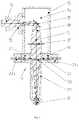
- FIG. 1shows a sectional view of a laser cutting head 10 having a gas guide 11 .
- Such laser cutting heads 10are used, for example, in laser cutting machines.
- the laser cutting head 10has a base body 12 with an interior 14 , which is designed as a clean room.
- a laser source 16for example, a fibre laser, is attached to the outside of the base body 12 and produces a laser beam 18 directed into the interior 14 .
- reference numeral 16can denote a coupling member, with which a laser beam of an external laser source exits.
- the coupling membermay be, for example, a fibre plug having an end cap.
- the laser beam 18enters the interior 14 via a fibre bushing 13 .
- the laser beam 18further extends to a deflecting element 15 such as a mirror.
- the deflected laser beam 18passes through a lens 17 .
- the laser beam 18leaves the interior 14 through the base body 12 .
- the laser beam 18then enters the gas guide 11 , where it meets a gas flow 20 .
- the laser beam 18leaves the gas guide 11 and thus the laser cutting head 10 through the nozzle or nozzle electrode 19 .
- the gas guide 11here consists of a plurality of parts, consisting at least of one upper part 21 , one or a plurality of gas inlets 23 a and 23 b , at least one pressure chamber 24 and at least one lower part 22 .
- the pressure chamber 24which can be divided into a plurality of recesses or areas, can be formed by the upper part 21 and the lower part 22 .
- the gas guide 11is axis symmetrical and/or rotationally symmetrical with respect to a flow axis S.
- the flow axis Scorresponds to the optical axis of the laser beam 18 in the area of the lower part and indicates the central axis of the gas flow in the direction of the nozzle electrode 19 .
- the two gas inlets 23 a and 23 bare arranged concentrically with respect to flow axis S.
- the gas flowwhich is initially radial in the gas inlets 23 a and 23 b , is deflected into an axial gas flow.
- FIG. 2shows a sectional view of a gas guide 11 a according to a first exemplary embodiment.
- the sectional viewis perpendicular to the sectional view of FIG. 1 , so that the flow axis is a surface normal to the sheet plane.
- the upper part 21 a and the lower part 22 a as well as the gas flow channels 25 a and 25 bare shaped such that the gas flow 20 a , which flows through the gas inlets 23 c and 23 d , does not strike a surface frontally, but rather flows, in a flow-optimised manner, into a pressure chamber or into at least two areas or recesses 24 a and 24 b of the pressure chamber.
- the gas flow 20 acan calm down in the pressure chamber, ensuring fewer eddies.
- the gasis guided to the nozzle 19 along the wall in the downward-oriented manner via at least four gas conduits 26 a —ten gas conduits 26 a in the example shown—and at least one equalising channel 27 a .
- the equalising channel 27 ais formed concentrically around the flow axis.
- FIG. 3shows a sectional view of a gas guide 11 b according to a second exemplary embodiment.
- the upper part 21 b and the lower part 22 b as well as the gas flow channels 25 c and 25 dare shaped such that the gas flow 20 b , which flows through the gas inlets 23 e and 23 f , does not strike a surface frontally, but rather flows, in a flow-optimised manner, into, in this case four, pressure chambers 24 c , 24 d , 24 e and 24 f , where the gas flow 20 b is able to calm down, thus ensuring fewer eddies.
- the gas flow channels 25 c and 25 d hereeach comprise four subchannels, between which a gas-conducting element is provided in the form of a flow divider.
- the gasis guided to the nozzle 19 along the wall in the downward-oriented manner via at least four gas conduits 26 b —eight gas conduits 26 b in the example shown—and at least one equalising channel 27 b .
- a plurality of gas conduits 26 bthus open or merge into an equalising channel 27 b.
- FIG. 4shows a sectional view of the gas guide 11 c according to the first and second exemplary embodiments, having the upper part 21 c and the lower part 22 c.
- FIG. 5shows an enlarged detail of area X of FIG. 4 .
- the function of the gas flow 20 cwhich flows from the pressure chamber 24 g into the equalising channel 27 c via the gas conduit 26 c , is described with reference to FIG. 5 . Directed in this way, the gas flow 20 c flows to the nozzle 19 along the wall of the lower part.
- the gas flow 20 cis first guided into the pressure chamber 24 g via a plurality of gas inlets (not shown here). This feed can extend perpendicular, that is to say radially, or essentially perpendicular to flow axis S.
- the gas inletscan also run into the pressure chamber 24 g at an angle.
- the gas flow 20 cextends into the gas conduit 26 c starting from the pressure chamber 24 g . At least four gas conduits are provided, one gas conduit 26 c of which is shown.
- the gas conduitscan each be formed between two ribs.
- the ribs and the gas conduitsfirst extend in a radial direction and then in an increasingly axial direction towards the nozzle or towards a workpiece.
- the gas conduits 26 cthen merge into the equalising channel 27 c , which is formed concentrically around flow axis S.
- the equalising channel 27 ccomprises an outflow port 28 at its lower edge in the flow direction.
- the gas conduits 26 c and the equalising channel 27 cor its outer contour remote from flow axis S, extend at a, preferably continuously, changing angle with respect to flow axis S.
- the angle with respect to flow axis Sdecreases in flow direction, that is from top to bottom. In other words, the angle gets increasingly shallower. This design results in no torsion being generated with respect to flow axis S.
- the gas conduitseach have a corresponding outflow port.
- the outflow port 28is formed in a convex manner for the gas flow 20 c on the radially outer side.
- the cross-sections of the at least two gas flow channels 25 a , 25 b , 25 c , 25 d , of the connection and the gas inlets 23 a and 23 b , respectively, of the pressure chamber 24 , the gas conduits 26 a , 26 b and of the equalising channel 27 care dimensioned such that the gas or gas flow 20 d has a maximum flow rate at the outflow port 28 from the equalising channel 27 c and the gas conduits 26 a , 26 b , respectively.
- the cross-sectionsare not considered individually, for example, per gas conduit, but as a whole, that is for all gas conduits. Accordingly, the cross-section of the gas conduits is derived by multiplying the number of gas conduits with the respective individual cross-sections. The smallest cross-section is in the area of the outflow port 28 .
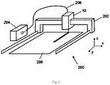
- FIG. 6shows a schematic perspective view of a laser cutting machine 200 having a laser cutting head 10 .
- the laser cutting head 10is arranged on a movable bridge 202 , so that it can be moved in at least the x and y directions.
- a laser source 204generates laser light and feeds it to the laser cutting head 10 via an optical fibre.
- a workpiece 208for example a sheet, is cut by the laser beam.
- the gas guide 11 presented here, or the laser cutting head 10 equipped therewith, or the laser cutting machine 200 equipped therewith,allows flow-mechanically optimised gas flow, as a result of which gas consumption can be reduced, and cutting quality and/or cutting rate improved.
Landscapes
- Engineering & Computer Science (AREA)
- Physics & Mathematics (AREA)
- Optics & Photonics (AREA)
- Plasma & Fusion (AREA)
- Mechanical Engineering (AREA)
- Laser Beam Processing (AREA)
Abstract
Description
The invention relates to a gas guide for a laser cutting head, a laser cutting head, and a laser cutting machine having a laser cutting head. In particular, the invention relates to a gas guide according to claim1, a laser cutting head according toclaim 13, and a laser cutting machine according toclaim 14.
A machine tool is used to manufacture and machine workpieces using tools. As machine tools, for example, laser processing machines, in particular laser cutting machines are considered here. In addition, laser processing machines can also be used for engraving, structuring, welding, heat treating as well as, for example, surface layer hardening and coating, as well as for volume-building processes such as rapid prototyping or selective sintering.
A cutting gas feed for feeding a cutting gas is provided in laser processing machines. A cutting gas feed has one or more external connections for connection to a gas source, and a plurality of channels or cut-outs on the inside for guiding and distributing the cutting gas. The cutting gas supports the burning process during flame cutting (with oxygen as the cutting gas), and the outflow of slag during fusion cutting.
The cutting quality depends, among other things, on the gas flow. In this way, turbulence or eddies in the gas flow can generate disturbances at the cutting edge.
The object of the invention is to avoid the disadvantages of the prior art and to provide an improved gas guide. Alternative objects are to provide an improved laser cutting head or an improved laser cutting machine.
These objects are achieved by a gas guide according to claim1, a laser cutting head according toclaim 13 and a laser processing machine according toclaim 14, respectively.
The gas guide according to the invention for a laser cutting head having a nozzle, having a central flow axis, comprises a base part having a pressure chamber concentrically surrounding the flow axis, configured for the reception of a gas flow, wherein the base part has at least four gas conduits, which extend from the pressure chamber in the direction of the flow axis, and wherein the cross-sections of the pressure chamber and the gas conduits are dimensioned such that the gas has a maximum flow rate when it exits the gas conduits.
The gas guide according to the invention has a continuous cross-section optimisation of the gas or fluid path. This has the advantage of an optimised gas or fluid flow, in which turbulence or eddies are avoided. In this way, the gas or fluid reaches its maximum flow rate when it exits the guide into a nozzle interior, into which the laser beam extends. The speed of the gas or fluid can be increased continuously by the gas guide during progress. For the sake of clarity, the expression gas shall be used henceforth; other fluids are also encompassed. The pressure chamber can be formed as a ring and, in conjunction with the gas conduits, serves to deflect the gas flow in the direction of the flow axis. The gas conduit can be seen as a channel, e.g. a delimited space having an elongated form for guiding the gas or fluid flow.
The optimisation of the flow has the advantage that losses in the gas flow are minimised, which means that more energy is available for the cutting process. In addition, the cutting quality can be improved, and/or the cutting rate increased.
It can be provided that at least two gas flow channels are provided between the pressure chamber and at least one gas inlet, wherein the at least two gas flow channels open tangentially and/or radially into the pressure chamber. The division into a plurality of, preferably a total of four to eight, gas flow channels allows a more precise distribution of the gas flow into the pressure chamber. The gas flow channels may include or consist of a delimited space having an elongated form for guiding the gas or fluid flow.
It can further be provided that a gas-conducting element is provided between the at least two gas flow channels. The gas-conducting element can, for example, have a tip or edge arranged between two gas flow channels in order to guide the flow to the gas flow channels. Depending on the number of gas flow channels, a plurality of gas-conducting elements can be provided. The gas-conducting element may define a part of the channels. Further, the gas-conducting element may divide the channels. The gas-conducting element may divide the gas inlet into the gas flow channels.
It can be provided that the cross-sections of the at least two gas flow channels, of the gas inlet, of the pressure chamber and the gas conduits are dimensioned such that the gas has a maximum flow rate when it exits the gas conduits. In the case of existing gas flow channels, these are also optimised in the cross-section in order to achieve an optimised gas guide.
It can further be provided that the pressure chamber has a continuous recess, two recesses comprising areas connected to an equalisation port, or four mutually separate recesses. The division or subdivision of the pressure chamber can further optimise the gas guide. When the gas flows into the pressure chamber, the flow must split into two directions. If gas is introduced into the pressure chamber from two sides, disturbances will occur when the two gas flows meet. If this meeting takes place within the pressure chamber, the effects are smaller. Thus, there should be a partition or a web in this area. This supporting geometry means there is less turbulence.
It can be provided that at least two gas flow channels open into each recess. This arrangement supports the disturbance-reduced inflow of the gas from the gas flow channels into the chamber.
It can further be provided that at least four to twenty-four, preferably twenty-two, gas conduits are provided. It has been shown that this number of gas conduits allows an optimised distribution of the entire gas flow. A higher number of gas conduits may be provided.
It can be provided that the gas conduits are arranged concentrically around the flow axis. It has been shown that this arrangement of the gas conduits allows an optimised distribution of the gas flow. If the pressure chamber is divided into a plurality of recesses or areas, which can be realised, for example, by means of webs located therebetween, the concentric arrangement can be maintained.
It can further be provided that a concentrically circumferential equalising channel adjoins the gas conduits. This equalising channel, which may have the shape of a concentric ring segment, is where the outlets of the gas conduits open into. The individual flows of the gas conduits meet accordingly in the equalising channel, as a result of which they are combined, which results in a calmer overall flow.
It can be provided that the gas conduits and/or the equalising channel each have an outflow port, wherein an outer contour of the equalising channel remote from the flow axis and/or the outflow port extends at a decreasing angle with respect to the flow axis. The decreasing angle allows the Coanda effect to build up, which favours the flow guide, since the gas flow is basically drawn further along the contour of the equalising channel or along the contour of the gas conduit.
It can be provided that the cross-sections of the at least two gas flow channels, of the pressure chamber, of the gas conduits and the equalising channel or of the pressure chamber, the gas conduits and of the equalising channel are dimensioned such that the gas has a maximum flow rate when it exits the equalising channel in the area of the outflow port. In the case of an existing equalising channel and/or existing gas inlets, these can also be optimised in the cross-section in order to achieve an optimised gas guide.
It can further be provided that the gas guide has an upper part and a lower part, wherein the pressure chamber, the gas conduits and/or the equalising channel are formed between the upper part and the lower part. This construction allows simple manufacturing, where, for example, the pressure chamber and the gas conduits may be milled. Alternatively, a one-piece construction can be provided, the production of which would be possible, for example, using additive manufacturing or rapid prototyping.
A laser cutting head according to the invention for a laser cutting machine comprises a laser feed, a nozzle, and a gas guide as described above. Otherwise the same advantages and modifications apply as described above.
A laser cutting machine according to the invention comprises a laser cutting head as described above and/or a gas guide as described above. The same advantages and modifications apply as described above.
Further preferred embodiments of the invention will become apparent from the remaining features mentioned in the dependent claims.
The various embodiments of the invention mentioned in this application can, unless otherwise stated in individual cases, be advantageously combined with one another.
The invention will be explained below in exemplary embodiments with reference to the accompanying drawings. In the figures:
Thelaser cutting head 10 has abase body 12 with an interior14, which is designed as a clean room. Alaser source 16, for example, a fibre laser, is attached to the outside of thebase body 12 and produces alaser beam 18 directed into the interior14. Alternatively,reference numeral 16 can denote a coupling member, with which a laser beam of an external laser source exits. The coupling member may be, for example, a fibre plug having an end cap.
Thelaser beam 18 enters the interior14 via afibre bushing 13. Thelaser beam 18 further extends to a deflectingelement 15 such as a mirror. The deflectedlaser beam 18 passes through alens 17. Finally, thelaser beam 18 leaves the interior14 through thebase body 12. Thelaser beam 18 then enters thegas guide 11, where it meets agas flow 20. Thelaser beam 18 leaves thegas guide 11 and thus thelaser cutting head 10 through the nozzle ornozzle electrode 19.
Thegas guide 11 here consists of a plurality of parts, consisting at least of oneupper part 21, one or a plurality ofgas inlets pressure chamber 24 and at least onelower part 22. By changing the geometry of theupper part 21 and thelower part 22 and the position and number of thegas inlets gas flow 20 can be positively influenced for the cutting process. Thepressure chamber 24, which can be divided into a plurality of recesses or areas, can be formed by theupper part 21 and thelower part 22.
Thegas guide 11 is axis symmetrical and/or rotationally symmetrical with respect to a flow axis S. The flow axis S corresponds to the optical axis of thelaser beam 18 in the area of the lower part and indicates the central axis of the gas flow in the direction of thenozzle electrode 19. The twogas inlets gas guide 11, the gas flow, which is initially radial in thegas inlets
Here, theupper part 21aand thelower part 22aas well as thegas flow channels gas flow 20a, which flows through thegas inlets gas flow 20acan calm down in the pressure chamber, ensuring fewer eddies. The gas is guided to thenozzle 19 along the wall in the downward-oriented manner via at least fourgas conduits 26a—tengas conduits 26ain the example shown—and at least one equalisingchannel 27a. The equalisingchannel 27ais formed concentrically around the flow axis.
The gas flow20cis first guided into the pressure chamber24gvia a plurality of gas inlets (not shown here). This feed can extend perpendicular, that is to say radially, or essentially perpendicular to flow axis S. The gas inlets can also run into the pressure chamber24gat an angle. The gas flow20cextends into the gas conduit26cstarting from the pressure chamber24g. At least four gas conduits are provided, one gas conduit26cof which is shown.
The gas conduits can each be formed between two ribs. The ribs and the gas conduits first extend in a radial direction and then in an increasingly axial direction towards the nozzle or towards a workpiece.
The gas conduits26cthen merge into the equalising channel27c, which is formed concentrically around flow axis S. The equalising channel27ccomprises anoutflow port 28 at its lower edge in the flow direction. The gas conduits26cand the equalising channel27c, or its outer contour remote from flow axis S, extend at a, preferably continuously, changing angle with respect to flow axis S. The angle with respect to flow axis S decreases in flow direction, that is from top to bottom. In other words, the angle gets increasingly shallower. This design results in no torsion being generated with respect to flow axis S. If there is no equalising channel, the gas conduits each have a corresponding outflow port. Theoutflow port 28 is formed in a convex manner for the gas flow20con the radially outer side.
This design of the equalising channel27cor theoutflow port 28 leads to the formation of the Coanda effect, which favours the flow guide, since the gas flow20cis basically drawn further along the contour of the equalising channel27cor along the contour of the gas conduit26c.
The cross-sections of the at least twogas flow channels gas inlets pressure chamber 24, thegas conduits outflow port 28 from the equalising channel27cand thegas conduits
The cross-sections are not considered individually, for example, per gas conduit, but as a whole, that is for all gas conduits. Accordingly, the cross-section of the gas conduits is derived by multiplying the number of gas conduits with the respective individual cross-sections. The smallest cross-section is in the area of theoutflow port 28.
Thegas guide 11 presented here, or thelaser cutting head 10 equipped therewith, or thelaser cutting machine 200 equipped therewith, allows flow-mechanically optimised gas flow, as a result of which gas consumption can be reduced, and cutting quality and/or cutting rate improved.
Claims (14)
1. A gas guide for a laser cutting head having a nozzle having a central flow axis, comprising:
a base part having a pressure chamber concentrically surrounding the central flow axis, and configured to receive a gas flow,
wherein the base part has at least four gas conduits, which communicate with the pressure chamber, and
wherein dimensions of the cross-sections of the pressure chamber and of the at least four gas conduits are configured such that the gas has a maximum flow rate when a gas exits the at least four gas conduits,
wherein the at least four gas conduits each extend from the pressure chamber in a flow direction of the gas flow to a gas conduit terminal end within the base part at a decreasing angle with respect to the central flow axis,
wherein an outer contour of an equalizing channel, remote from the central flow axis, extends from the at least four gas conduits in the flow direction of the gas flow at a decreasing angle with respect to the central flow axis.
2. The gas guide according toclaim 1 , wherein at least two gas flow channels are provided between the pressure chamber and at least one gas inlet, wherein the at least two gas flow channels open tangentially and/or radially into the pressure chamber.
3. The gas guide according toclaim 2 , wherein a gas-conducting element is provided between the at least two gas flow channels.
4. The gas guide according toclaim 2 , wherein dimensions of the cross-sections of the at least two gas flow channels, of the gas inlet, of the pressure chamber, and of the at least four gas conduits are configured such that the gas has a maximum flow rate when the gas exits the at least four gas conduits.
5. The gas guide according toclaim 1 , wherein the pressure chamber comprises (i) a continuous recess, (ii) two recesses comprising areas connected with an equalization port, or (iii) four mutually separate recesses.
6. The gas guide according toclaim 2 , wherein the at least two gas flow channels open into each recess.
7. The gas guide according toclaim 1 , wherein at least four to twenty-four gas conduits are provided.
8. The gas guide according toclaim 1 , wherein the at least four gas conduits are arranged concentrically around the central flow axis.
9. The gas guide according toclaim 1 , wherein dimensions of the cross-sections of the at least two gas flow channels, of the pressure chamber, of the at least four gas conduits and of the equalizing channel or of the pressure chamber, the at least four gas conduits and of the equalizing channel are configured such that the gas has a maximum flow rate in the area of the outflow port.
10. The gas guide according toclaim 1 , wherein the gas guide has an upper part and a lower part, wherein the pressure chamber, the at least four gas conduits and/or the equalizing channel are formed between the upper part and the lower part.
11. A laser cutting head for a laser cutting machine, wherein a laser feed, a nozzle and a gas guide according toclaim 1 are provided.
12. A laser cutting machine having a laser cutting head according toclaim 11 .
13. A laser cutting machine comprising:
a laser cutting head comprising a nozzle having a central flow;
a gas guide for the laser cutting head comprising:
a base part having a pressure chamber concentrically surrounding the central flow axis and configured to receive a gas flow,
wherein the base part has at least four gas conduits, which communicate with the pressure chamber, and
wherein dimension of the cross-section of the pressure chamber and of the at least four gas conduits are configured such that the gas has a maximum flow rate when a gas exits the at least four gas conduits,
wherein the at least four gas conduits each extend from the pressure chamber in a flow direction of the gas flow to a gas conduit terminal end within the base part at a decreasing angle with respect to the central flow axis.
14. A gas guide for a laser cutting head having a nozzle having a central flow axis, comprising:
a base part having a pressure chamber concentrically surrounding the central flow axis, the base part being configured to receive a gas flow,
wherein the base part has at least four gas conduits, which communicate with the pressure chamber, and
wherein the dimensions of cross-sections of the pressure chamber and of the at least four gas conduits are configured such that the gas has a maximum flow rate when a gas exits the at least four gas conduits,
wherein the at least four gas conduits each extend from the pressure chamber in a flow direction of the gas flow at a decreasing angle with respect to the central flow axis,
wherein a concentrically circumferential equalizing channel adjoins the gas conduits, and
wherein at least two gas flow channels are provided between the pressure chamber and at least one gas inlet, wherein the at least two gas flow channels open tangentially and/or radially into the pressure chamber.
Applications Claiming Priority (3)
| Application Number | Priority Date | Filing Date | Title |
|---|---|---|---|
| DE102019103659.3ADE102019103659B4 (en) | 2019-02-13 | 2019-02-13 | Gas guide, laser cutting head and laser cutting machine |
| DE102019103659.3 | 2019-02-13 | ||
| PCT/EP2020/053778WO2020165354A1 (en) | 2019-02-13 | 2020-02-13 | Gas guide, laser cutting head and laser cutting machine |
Publications (2)
| Publication Number | Publication Date |
|---|---|
| US20220040788A1 US20220040788A1 (en) | 2022-02-10 |
| US11465238B2true US11465238B2 (en) | 2022-10-11 |
Family
ID=69770858
Family Applications (1)
| Application Number | Title | Priority Date | Filing Date |
|---|---|---|---|
| US17/414,818ActiveUS11465238B2 (en) | 2019-02-13 | 2020-02-13 | Gas guide, laser cutting head and laser cutting machine |
Country Status (6)
| Country | Link |
|---|---|
| US (1) | US11465238B2 (en) |
| EP (1) | EP3924139B1 (en) |
| JP (1) | JP7154430B2 (en) |
| CN (1) | CN113439004B (en) |
| DE (1) | DE102019103659B4 (en) |
| WO (1) | WO2020165354A1 (en) |
Families Citing this family (1)
| Publication number | Priority date | Publication date | Assignee | Title |
|---|---|---|---|---|
| CN114309982B (en)* | 2021-12-31 | 2025-01-21 | 西安中科微精光子科技股份有限公司 | Laser cutting device |
Citations (136)
| Publication number | Priority date | Publication date | Assignee | Title |
|---|---|---|---|---|
| US2874265A (en)* | 1956-05-23 | 1959-02-17 | Union Carbide Corp | Non-transferred arc torch process and apparatus |
| US3015127A (en)* | 1956-12-28 | 1962-01-02 | Owens Corning Fiberglass Corp | Method and apparatus for forming fibers |
| US3503804A (en)* | 1967-04-25 | 1970-03-31 | Hellmut Schneider | Method and apparatus for the production of sonic or ultrasonic waves on a surface |
| US3525474A (en)* | 1968-12-09 | 1970-08-25 | Us Air Force | Jet pump or thrust augmentor |
| US3567898A (en)* | 1968-07-01 | 1971-03-02 | Crucible Inc | Plasma arc cutting torch |
| US3569660A (en)* | 1968-07-29 | 1971-03-09 | Nat Res Dev | Laser cutting apparatus |
| US4000392A (en)* | 1974-07-01 | 1976-12-28 | United Technologies Corporation | Fusion zone purification by controlled laser welding |
| US4010345A (en)* | 1975-05-02 | 1977-03-01 | United Technologies Corporation | Gas delivery means for cutting with laser radiation |
| US4027137A (en)* | 1975-09-17 | 1977-05-31 | International Business Machines Corporation | Laser drilling nozzle |
| US4031351A (en)* | 1972-10-25 | 1977-06-21 | Groupement Atomique Alsacienne Atlantique | High energy laser beam cutting method and apparatus |
| US4047580A (en)* | 1974-09-30 | 1977-09-13 | Chemical Grout Company, Ltd. | High-velocity jet digging method |
| US4078167A (en)* | 1977-02-09 | 1978-03-07 | United Technologies Corporation | Welding shield and plasma suppressor apparatus |
| US4121085A (en)* | 1976-05-07 | 1978-10-17 | Caterpillar Tractor Co. | Gas nozzle for laser welding |
| US4125757A (en)* | 1977-11-04 | 1978-11-14 | The Torrington Company | Apparatus and method for laser cutting |
| US4288678A (en)* | 1979-03-05 | 1981-09-08 | Fiat Auto S.P.A. | Apparatus for treating metal workpieces with laser radiation |
| US4324972A (en)* | 1979-11-21 | 1982-04-13 | Laser-Work A.G. | Process and device for laser-beam melting and flame cutting |
| US4642445A (en)* | 1985-06-28 | 1987-02-10 | Westinghouse Electric Corp. | Shielding apparatus for metal processing operations |
| US4672171A (en)* | 1985-03-21 | 1987-06-09 | United Centrifugal Pumps | Plasma transfer welded arc torch |
| US4724299A (en)* | 1987-04-15 | 1988-02-09 | Quantum Laser Corporation | Laser spray nozzle and method |
| US4764656A (en)* | 1987-05-15 | 1988-08-16 | Browning James A | Transferred-arc plasma apparatus and process with gas heating in excess of anode heating at the workpiece |
| US4992643A (en)* | 1989-08-25 | 1991-02-12 | United States Department Of Energy | Method and device for controlling plume during laser welding |
| US5237150A (en)* | 1990-01-19 | 1993-08-17 | Fanuc Ltd. | Method of cutting workpiece with laser beam |
| US5239552A (en)* | 1991-04-01 | 1993-08-24 | Miyachi Technos Corporation | Laser output unit |
| US5285045A (en)* | 1991-10-25 | 1994-02-08 | Brother Kogyo Kabushiki Kaisha | Laser processing apparatus |
| US5356081A (en)* | 1993-02-24 | 1994-10-18 | Electric Power Research Institute, Inc. | Apparatus and process for employing synergistic destructive powers of a water stream and a laser beam |
| US5359176A (en)* | 1993-04-02 | 1994-10-25 | International Business Machines Corporation | Optics and environmental protection device for laser processing applications |
| US5418350A (en)* | 1992-01-07 | 1995-05-23 | Electricite De Strasbourg (S.A.) | Coaxial nozzle for surface treatment by laser irradiation, with supply of materials in powder form |
| US5609781A (en)* | 1992-10-23 | 1997-03-11 | Mitsubishi Denki Kabushiki Kaisha | Machining head and laser machining apparatus |
| US5660748A (en)* | 1995-02-28 | 1997-08-26 | Mitsubishi Denki Kabushiki Kaisha | Laser beam machine with an optical fiber cable |
| US5705785A (en)* | 1994-12-30 | 1998-01-06 | Plasma-Laser Technologies Ltd | Combined laser and plasma arc welding torch |
| US5728993A (en)* | 1995-08-05 | 1998-03-17 | The Boc Group Plc | Laser cutting of materials with plural beams |
| US5756962A (en)* | 1994-08-02 | 1998-05-26 | Mcneil - Ppc, Inc. | Laser-processing head for laser processing apparatus |
| US5866870A (en)* | 1994-11-24 | 1999-02-02 | Coventry University | Enhanced laser beam welding |
| US5902499A (en)* | 1994-05-30 | 1999-05-11 | Richerzhagen; Bernold | Method and apparatus for machining material with a liquid-guided laser beam |
| US5981901A (en)* | 1991-11-29 | 1999-11-09 | La Rocca; Aldo Vittorio | Method and device for gas shielding laser processed work pieces |
| JP2000225488A (en) | 1999-02-08 | 2000-08-15 | Amada Eng Center Co Ltd | Assist gas injection method in thermal cutting machine and machining head therefor |
| US6118097A (en)* | 1992-10-23 | 2000-09-12 | Mitsubishi Denki Kabushiki Kaisha | Machining head and laser machining apparatus |
| US6144010A (en)* | 1997-05-12 | 2000-11-07 | Sumitomo Heavy Industries, Ltd. | Method of removing coating film with laser beam and laser processing system |
| US6172323B1 (en)* | 1997-02-10 | 2001-01-09 | Mitsubishi Heavy Industries, Ltd. | Combined laser and plasma arc welding machine |
| US6198070B1 (en)* | 1998-07-23 | 2001-03-06 | Nippei Toyama Corporation | Laser beam machining method and laser beam machine |
| US6204475B1 (en)* | 1999-01-04 | 2001-03-20 | Fanuc Limited | Laser machining apparatus with transverse gas flow |
| US6248972B1 (en)* | 1999-04-30 | 2001-06-19 | Komatsu Ltd. | Plasma cutting method, device and gas supply system for plasma cutting torch |
| US6268583B1 (en)* | 1999-05-21 | 2001-07-31 | Komatsu Ltd. | Plasma torch of high cooling performance and components therefor |
| US6313432B1 (en)* | 1997-06-20 | 2001-11-06 | Tanaka Engineering Works, Ltd. | Laser cutting method and laser cutter |
| US6316743B1 (en)* | 1998-09-09 | 2001-11-13 | Tanaka Engineering Works, Ltd. | Laser piercing method, laser processing nozzle, and laser cutting apparatus |
| US20020003133A1 (en)* | 2000-05-11 | 2002-01-10 | Koichi Mukasa | Laser welding apparatus, a gas shielding apparatus and a method for controlling a laser welding apparatus |
| US20020008090A1 (en)* | 2000-05-09 | 2002-01-24 | Koichi Mukasa | Laser welding method and a laser welding apparatus |
| US20020023905A1 (en)* | 2000-07-27 | 2002-02-28 | Terukazu Fukaya | High density energy beam machining method and apparatus for the same |
| US6388227B1 (en)* | 1999-07-15 | 2002-05-14 | Plasma Laser Technologies Ltd. | Combined laser and plasma-arc processing torch and method |
| US20020179582A1 (en)* | 2001-05-07 | 2002-12-05 | Jenoptik Automatisierungstechnik Gmbh | Tool head for laser machining of materials |
| US6494965B1 (en)* | 2000-05-30 | 2002-12-17 | Creo Products Inc. | Method and apparatus for removal of laser ablation byproducts |
| US6525291B1 (en)* | 1999-09-21 | 2003-02-25 | Hypertherm, Inc. | Process and apparatus for cutting or welding a workpiece |
| US6583383B2 (en)* | 2000-05-09 | 2003-06-24 | Shinko Electric Industries Co., Ltd. | Method and apparatus for cutting a semiconductor wafer |
| US20030192865A1 (en)* | 2002-04-16 | 2003-10-16 | W.A. Whitney Co. | Method and apparatus for laser piercing and cutting metal sheet and plate |
| US20030197909A1 (en)* | 2002-02-08 | 2003-10-23 | Creo Inc. | Method and apparatus for preventing debris contamination of optical elements used for imaging |
| US20030217809A1 (en)* | 2002-05-22 | 2003-11-27 | Yukio Morishige | Laser machining method and apparatus |
| JP2004148360A (en) | 2002-10-30 | 2004-05-27 | Toppan Forms Co Ltd | Laser processing head and laser processing system using the same |
| US6744005B1 (en)* | 1999-10-11 | 2004-06-01 | Fraunhofer-Gesellschaft Zur Forderung Der Angewandten Forschung E.V. | Method for producing shaped bodies or applying coatings |
| US20040112882A1 (en)* | 2002-09-05 | 2004-06-17 | Hidekazu Miyairi | Laser processing apparatus |
| US6791061B2 (en)* | 2000-11-07 | 2004-09-14 | Matsushita Electric Industrial Co., Ltd. | Optical machining device |
| US20040188397A1 (en)* | 2003-03-31 | 2004-09-30 | Connally William J. | Process monitor for laser and plasma materials processing of materials |
| US6822187B1 (en)* | 1998-09-09 | 2004-11-23 | Gsi Lumonics Corporation | Robotically operated laser head |
| US20040232123A1 (en)* | 2001-10-05 | 2004-11-25 | Jean-Pascal Alfille | Laser cutting method and device |
| US6833222B1 (en)* | 2001-03-29 | 2004-12-21 | Dupont Photomasks, Inc. | Method and apparatus for trimming a pellicle film using a laser |
| US20050056628A1 (en)* | 2003-09-16 | 2005-03-17 | Yiping Hu | Coaxial nozzle design for laser cladding/welding process |
| US20050103763A1 (en)* | 2003-10-23 | 2005-05-19 | Honda Motor Co., Ltd. | Method of and apparatus for machining groove with laser beam |
| US20050109744A1 (en)* | 2002-02-08 | 2005-05-26 | Baker Martin C. | Hand-held laser welding wand having internal coolant and gas delivery conduits |
| US20050109745A1 (en)* | 2003-03-15 | 2005-05-26 | Michael Wessner | Laser processing head |
| US20050133486A1 (en)* | 2003-12-19 | 2005-06-23 | Baker Martin C. | Hand-held laser welding wand having removable filler media delivery extension tips |
| US20050189331A1 (en)* | 2002-12-20 | 2005-09-01 | Ian Millard | Laser ablation nozzle assembly |
| US20050211687A1 (en)* | 2002-04-01 | 2005-09-29 | Hirobumi Sonoda | Yag laser induced arc filler wire composite welding method and welding equipment |
| US20060043075A1 (en)* | 2004-08-30 | 2006-03-02 | Ady Hershcovitch | Shielded beam delivery apparatus and method |
| US7038161B2 (en)* | 2001-07-05 | 2006-05-02 | Snecma Moteurs | Welding unit with miniaturized laser beam |
| US20060163216A1 (en)* | 2005-01-27 | 2006-07-27 | Hypertherm, Inc. | Automatic gas control for a plasma arc torch |
| US20070012669A1 (en)* | 2005-07-15 | 2007-01-18 | Fanuc Ltd. | Laser processing head |
| US20070012668A1 (en)* | 2005-07-12 | 2007-01-18 | Fanuc Ltd. | Laser processing machine |
| US20070119834A1 (en)* | 2005-11-25 | 2007-05-31 | L'air Liquide Societe Anonyme Pour I'etude Et I'exploitation Des Procedes Georges Claude | Method for cutting stainless steel with a fiber laser |
| US20070119837A1 (en)* | 2005-11-30 | 2007-05-31 | Tokyo Electron Limited | Laser processing apparatus and laser processing method |
| US20070119833A1 (en)* | 2005-11-25 | 2007-05-31 | L'air Liquide Societe Anonyme Pour I'etude Et I'exploitation Des Procedes Georges Claude | METHOD FOR CUTTING C-Mn STEEL WITH A FIBER LASER |
| US20070145026A1 (en)* | 2005-12-22 | 2007-06-28 | Hidehisa Murase | Laser processing apparatus and laser processing method as well as debris extraction mechanism and debris extraction method |
| US20070278195A1 (en)* | 2004-11-10 | 2007-12-06 | Synova Sa | Method and Device for Generating a Jet of Fluid for Material Processing and Fluid Nozzle for Use in Said Device |
| US20080041832A1 (en)* | 2004-06-11 | 2008-02-21 | Neil Sykes | Process and Apparatus for Ablation |
| US20080067159A1 (en)* | 2006-09-19 | 2008-03-20 | General Electric Company | Laser processing system and method for material processing |
| US20080308538A1 (en)* | 2005-08-23 | 2008-12-18 | James Gordon Harris | Powder Delivery Nozzle |
| US20090084765A1 (en)* | 2007-09-28 | 2009-04-02 | Sugino Machine Limited | Laser machining apparatus using laser beam introduced into jet liquid column |
| US20090120917A1 (en)* | 2006-05-09 | 2009-05-14 | Trumpf Laser- Und Systemtechnik Gmbh | Laser Processing Machines and Methods for Providing a Gas to the Beam Guide of a Laser Processing Machine |
| US7626136B2 (en)* | 2004-02-03 | 2009-12-01 | Toyota Jidosha Kabushiki Kaisha | Powder metal cladding nozzle |
| US20090314753A1 (en)* | 2008-06-18 | 2009-12-24 | Electro Scientific Industries, Inc. | Debris capture and removal for laser micromachining |
| US20100044353A1 (en)* | 2006-10-30 | 2010-02-25 | Flemming Ove Elholm Olsen | Method and system for laser processing |
| US20100064986A1 (en)* | 2006-09-27 | 2010-03-18 | Babcock-Hitachi Kabushiki Kaisha | Burner, and combustion equipment and boiler comprising burner |
| US20100108648A1 (en)* | 2005-08-25 | 2010-05-06 | Ryoji Koseki | Hybrid laser processing apparatus |
| US20100163539A1 (en)* | 2008-12-26 | 2010-07-01 | Denso Corporation | Machining method and machining system for micromachining a part in a machine component |
| US20100187209A1 (en)* | 2007-08-03 | 2010-07-29 | Mitsubishi Electric Corporation | Laser machining nozzle |
| US20100217060A1 (en)* | 2006-05-29 | 2010-08-26 | Japan Atomic Energy Agency | Method of Decontaminating Radioisotope-Contaminated Surface Vicinity Region by Use of Nonthermal Laser Peeling Without Re-Melting, Without Re-Diffusion and Without Re-Contamination, and Apparatus Therefor |
| US20100282725A1 (en)* | 2006-05-24 | 2010-11-11 | Andrew Neil Johnson | Laser cutting head |
| US20100301013A1 (en)* | 2009-05-15 | 2010-12-02 | National University Of Ireland | Method for laser ablation |
| US20110095002A1 (en)* | 2008-07-09 | 2011-04-28 | Seiji Katayama | Laser lap welding method for galvanized steel sheets |
| US20110210109A1 (en)* | 2008-10-29 | 2011-09-01 | Trumpf Werkzeugmaschinen Gmbh + Co. Kg | Laser Processing Nozzles and Methods |
| US20120175354A1 (en)* | 2011-01-11 | 2012-07-12 | Halliburton Energy Services, Inc. | Purging and debris removal from holes |
| US20130298387A1 (en)* | 2012-05-14 | 2013-11-14 | Robert Bosch Gmbh | Method for producing an energy cell and apparatus for carrying out same |
| US20140034614A1 (en)* | 2011-04-21 | 2014-02-06 | Adige S.P.A. | Methods for controlling laser cutting processes and laser cutting systems implementing same |
| US8735769B2 (en)* | 2009-10-20 | 2014-05-27 | Hitachi, Ltd. | Laser processing head and laser cladding method |
| US20140154871A1 (en)* | 2012-11-30 | 2014-06-05 | Taiwan Semiconductor Manufacturing Company, Ltd. | Method and system for manufacturing semiconductor device |
| US20140251962A1 (en)* | 2011-10-13 | 2014-09-11 | Commissariat à l'énergie atomique et aux énergies alternatives | Apparatus and Method for Laser Cutting with a Laser Implementing Gas Pulses, the Frequency or Pressure of Which is Controlled |
| US8857733B1 (en)* | 2009-01-14 | 2014-10-14 | Resodyn Corporation | Flameless thermal spray system using flame heat source |
| US8940218B1 (en)* | 2012-08-20 | 2015-01-27 | Automated Assembly Corporation | De-focused laser etching of a light diffuser |
| US8974272B2 (en)* | 2011-05-20 | 2015-03-10 | Dyna-Tech Sales Corporation | Aspirating induction nozzle |
| DE102012025627A1 (en) | 2012-09-21 | 2015-05-28 | Trumpf Laser Gmbh | Ring nozzle for a laser processing head and laser processing head with it |
| US20150165559A1 (en)* | 2013-12-13 | 2015-06-18 | Jens Guenter Gaebelein | Methods and apparatus to perform a liquid-jet guided laser process and to simplify the maintenance thereof |
| US9061304B2 (en)* | 2011-08-25 | 2015-06-23 | Preco, Inc. | Method and apparatus for a clean cut with a laser |
| WO2015110887A1 (en) | 2014-01-22 | 2015-07-30 | Toyota Jidosha Kabushiki Kaisha | Laser processing apparatus |
| US20150352667A1 (en)* | 2012-12-20 | 2015-12-10 | 3M Innovative Properties Company | Material processing system with low-inertia laser scanning and end effector manipulation |
| US20160101483A1 (en)* | 2014-10-08 | 2016-04-14 | Kabushiki Kaisha Toshiba | Welding apparatus and nozzle device |
| US20160121427A1 (en)* | 2014-10-31 | 2016-05-05 | Prima Power Laserdyne, Llc | Cross jet laser welding nozzle |
| US20160129527A1 (en)* | 2014-11-11 | 2016-05-12 | Samsung Display Co., Ltd. | Laser cutting device |
| US20160325378A1 (en)* | 2014-03-18 | 2016-11-10 | Kabushiki Kaisha Toshiba | Nozzle of layered object manufacturing apparatus, and layered object manufacturing apparatus |
| US20170043432A1 (en)* | 2015-08-11 | 2017-02-16 | Disco Corporation | Laser processing apparatus |
| US20170120392A1 (en)* | 2015-10-30 | 2017-05-04 | Hypertherm, Inc. | Water Cooling of Laser Components |
| US20170182593A1 (en)* | 2014-06-16 | 2017-06-29 | Synova Sa | Machining head |
| US20170232558A1 (en)* | 2014-10-17 | 2017-08-17 | Mitsubishi Electric Corporation | Laser machining method and laser machining apparatus |
| US20170259377A1 (en)* | 2015-11-11 | 2017-09-14 | Technology Research Association For Future Additive Manufacturing | Processing nozzle, processing head, and optical machining apparatus |
| US20170334022A1 (en)* | 2015-10-30 | 2017-11-23 | Hypertherm, Inc. | Highly Positioned Laser Processing Nozzle |
| US20180093347A1 (en)* | 2016-03-15 | 2018-04-05 | Technology Research Association For Future Additive Manufacturing | Optical processing nozzle and optical processing apparatus |
| US20180147667A1 (en)* | 2016-11-28 | 2018-05-31 | United Technologies Corporation | Laser cladding system and method |
| US20180200832A1 (en)* | 2017-01-19 | 2018-07-19 | Fanuc Corporation | Nozzle for laser processing head |
| US20180200833A1 (en)* | 2017-01-19 | 2018-07-19 | Fanuc Corporation | Laser machine |
| US10092980B1 (en)* | 2014-05-30 | 2018-10-09 | Avonisys Ag | Method for coupling a laser beam into a liquid-jet |
| US20180315627A1 (en)* | 2015-10-26 | 2018-11-01 | The Japan Steel Works, Ltd. | Laser treatment device rectifier device and laser treatment device |
| JP6425678B2 (en) | 2016-03-23 | 2018-11-21 | 三菱電機株式会社 | Processing head of laser processing device |
| US20180354072A1 (en)* | 2015-12-02 | 2018-12-13 | Avonisys Ag | Laser beam processing device comprising a coupling device for coupling a focused laser beam into a fluid jet |
| US10220473B2 (en)* | 2015-11-11 | 2019-03-05 | Technology Research Association For Future Additive Manufacturing | Processing nozzle and optical machining apparatus |
| US10279417B2 (en)* | 2015-10-06 | 2019-05-07 | Hypertherm, Inc. | Controlling and delivering gases in a plasma arc torch and related systems and methods |
| US10654129B2 (en)* | 2014-02-27 | 2020-05-19 | Trumpf Laser- Und Systemtechnik Gmbh | Laser processing heads with a cross-jet nozzle |
| US10780634B2 (en)* | 2017-09-19 | 2020-09-22 | Technology Research Association For Future Additive Manufacturing | Nozzle, processing apparatus, and additive manufacturing apparatus |
| US10814424B2 (en)* | 2018-02-16 | 2020-10-27 | Fanuc Corporation | Laser machining head having function of rectifying assist gas |
| US20200361032A1 (en)* | 2018-02-02 | 2020-11-19 | Precitec Gmbh & Co. Kg | Gas supply device and laser processing head comprising same |
Family Cites Families (13)
| Publication number | Priority date | Publication date | Assignee | Title |
|---|---|---|---|---|
| IT1250872B (en)* | 1991-12-06 | 1995-04-21 | Altec Srl | METHOD FOR SUPPLYING AN ASSISTANCE GAS ON A PIECE SUBJECTED TO A LASER CUT AND CUTTING EQUIPMENT OPERATING ACCORDING TO SUCH METHOD |
| DE4402000C2 (en) | 1994-01-25 | 1996-04-11 | Fraunhofer Ges Forschung | Nozzle arrangement for laser beam cutting |
| JP2000225487A (en)* | 1999-02-08 | 2000-08-15 | Nippon Steel Corp | Laser cutting nozzle and laser cutting device |
| JP2001150172A (en)* | 1999-11-22 | 2001-06-05 | Koike Sanso Kogyo Co Ltd | Laser cutting equipment |
| JP5147445B2 (en)* | 2007-09-28 | 2013-02-20 | 株式会社スギノマシン | Laser processing equipment using laser light guided into the jet column |
| DE102008030783B3 (en)* | 2008-06-28 | 2009-08-13 | Trumpf Werkzeugmaschinen Gmbh + Co. Kg | Process for laser beam angle cutting of workpiece involving ultrasonic gas cutting stream generally useful in laser cutting operations gives higher quality products at increased cutting speeds |
| JP2011125906A (en)* | 2009-12-18 | 2011-06-30 | Komatsu Ntc Ltd | Nozzle for laser beam machining |
| KR20140112498A (en)* | 2011-12-07 | 2014-09-23 | 제너럴 아토믹스 | Methods and Systems for Use in Laser Machining |
| JP5895949B2 (en) | 2014-01-14 | 2016-03-30 | トヨタ自動車株式会社 | Powder overlay nozzle |
| JP6167055B2 (en)* | 2014-03-06 | 2017-07-19 | 三菱重工業株式会社 | Laser nozzle, laser processing apparatus, and laser processing method |
| CN103894742B (en) | 2014-04-01 | 2016-08-17 | 大族激光科技产业集团股份有限公司 | The auxiliary gas flow road of a kind of laser cutting head and method for designing thereof |
| DE112015005926B4 (en) | 2015-03-19 | 2021-02-04 | Mitsubishi Electric Corporation | Processing nozzle and laser beam processing device |
| CN105436720B (en) | 2015-12-04 | 2017-05-24 | 大族激光科技产业集团股份有限公司 | Laser cutting device and laser head thereof |
- 2019
- 2019-02-13DEDE102019103659.3Apatent/DE102019103659B4/enactiveActive
- 2020
- 2020-02-13JPJP2021547199Apatent/JP7154430B2/enactiveActive
- 2020-02-13USUS17/414,818patent/US11465238B2/enactiveActive
- 2020-02-13CNCN202080014067.4Apatent/CN113439004B/enactiveActive
- 2020-02-13WOPCT/EP2020/053778patent/WO2020165354A1/ennot_activeCeased
- 2020-02-13EPEP20709499.6Apatent/EP3924139B1/enactiveActive
Patent Citations (149)
| Publication number | Priority date | Publication date | Assignee | Title |
|---|---|---|---|---|
| US2874265A (en)* | 1956-05-23 | 1959-02-17 | Union Carbide Corp | Non-transferred arc torch process and apparatus |
| US3015127A (en)* | 1956-12-28 | 1962-01-02 | Owens Corning Fiberglass Corp | Method and apparatus for forming fibers |
| US3503804A (en)* | 1967-04-25 | 1970-03-31 | Hellmut Schneider | Method and apparatus for the production of sonic or ultrasonic waves on a surface |
| US3567898A (en)* | 1968-07-01 | 1971-03-02 | Crucible Inc | Plasma arc cutting torch |
| US3569660A (en)* | 1968-07-29 | 1971-03-09 | Nat Res Dev | Laser cutting apparatus |
| US3525474A (en)* | 1968-12-09 | 1970-08-25 | Us Air Force | Jet pump or thrust augmentor |
| US4031351A (en)* | 1972-10-25 | 1977-06-21 | Groupement Atomique Alsacienne Atlantique | High energy laser beam cutting method and apparatus |
| US4000392A (en)* | 1974-07-01 | 1976-12-28 | United Technologies Corporation | Fusion zone purification by controlled laser welding |
| US4047580A (en)* | 1974-09-30 | 1977-09-13 | Chemical Grout Company, Ltd. | High-velocity jet digging method |
| US4010345A (en)* | 1975-05-02 | 1977-03-01 | United Technologies Corporation | Gas delivery means for cutting with laser radiation |
| US4027137A (en)* | 1975-09-17 | 1977-05-31 | International Business Machines Corporation | Laser drilling nozzle |
| US4121085A (en)* | 1976-05-07 | 1978-10-17 | Caterpillar Tractor Co. | Gas nozzle for laser welding |
| US4078167A (en)* | 1977-02-09 | 1978-03-07 | United Technologies Corporation | Welding shield and plasma suppressor apparatus |
| US4125757A (en)* | 1977-11-04 | 1978-11-14 | The Torrington Company | Apparatus and method for laser cutting |
| US4288678A (en)* | 1979-03-05 | 1981-09-08 | Fiat Auto S.P.A. | Apparatus for treating metal workpieces with laser radiation |
| US4324972A (en)* | 1979-11-21 | 1982-04-13 | Laser-Work A.G. | Process and device for laser-beam melting and flame cutting |
| US4672171A (en)* | 1985-03-21 | 1987-06-09 | United Centrifugal Pumps | Plasma transfer welded arc torch |
| US4642445A (en)* | 1985-06-28 | 1987-02-10 | Westinghouse Electric Corp. | Shielding apparatus for metal processing operations |
| US4724299A (en)* | 1987-04-15 | 1988-02-09 | Quantum Laser Corporation | Laser spray nozzle and method |
| US4764656A (en)* | 1987-05-15 | 1988-08-16 | Browning James A | Transferred-arc plasma apparatus and process with gas heating in excess of anode heating at the workpiece |
| US4992643A (en)* | 1989-08-25 | 1991-02-12 | United States Department Of Energy | Method and device for controlling plume during laser welding |
| US5237150A (en)* | 1990-01-19 | 1993-08-17 | Fanuc Ltd. | Method of cutting workpiece with laser beam |
| US5239552A (en)* | 1991-04-01 | 1993-08-24 | Miyachi Technos Corporation | Laser output unit |
| US5285045A (en)* | 1991-10-25 | 1994-02-08 | Brother Kogyo Kabushiki Kaisha | Laser processing apparatus |
| US5981901A (en)* | 1991-11-29 | 1999-11-09 | La Rocca; Aldo Vittorio | Method and device for gas shielding laser processed work pieces |
| US5418350A (en)* | 1992-01-07 | 1995-05-23 | Electricite De Strasbourg (S.A.) | Coaxial nozzle for surface treatment by laser irradiation, with supply of materials in powder form |
| US6118097A (en)* | 1992-10-23 | 2000-09-12 | Mitsubishi Denki Kabushiki Kaisha | Machining head and laser machining apparatus |
| US5609781A (en)* | 1992-10-23 | 1997-03-11 | Mitsubishi Denki Kabushiki Kaisha | Machining head and laser machining apparatus |
| US5356081A (en)* | 1993-02-24 | 1994-10-18 | Electric Power Research Institute, Inc. | Apparatus and process for employing synergistic destructive powers of a water stream and a laser beam |
| US5359176A (en)* | 1993-04-02 | 1994-10-25 | International Business Machines Corporation | Optics and environmental protection device for laser processing applications |
| US5902499A (en)* | 1994-05-30 | 1999-05-11 | Richerzhagen; Bernold | Method and apparatus for machining material with a liquid-guided laser beam |
| US5756962A (en)* | 1994-08-02 | 1998-05-26 | Mcneil - Ppc, Inc. | Laser-processing head for laser processing apparatus |
| US5866870A (en)* | 1994-11-24 | 1999-02-02 | Coventry University | Enhanced laser beam welding |
| US5705785A (en)* | 1994-12-30 | 1998-01-06 | Plasma-Laser Technologies Ltd | Combined laser and plasma arc welding torch |
| US5660748A (en)* | 1995-02-28 | 1997-08-26 | Mitsubishi Denki Kabushiki Kaisha | Laser beam machine with an optical fiber cable |
| US5728993A (en)* | 1995-08-05 | 1998-03-17 | The Boc Group Plc | Laser cutting of materials with plural beams |
| US6172323B1 (en)* | 1997-02-10 | 2001-01-09 | Mitsubishi Heavy Industries, Ltd. | Combined laser and plasma arc welding machine |
| US6144010A (en)* | 1997-05-12 | 2000-11-07 | Sumitomo Heavy Industries, Ltd. | Method of removing coating film with laser beam and laser processing system |
| US6313432B1 (en)* | 1997-06-20 | 2001-11-06 | Tanaka Engineering Works, Ltd. | Laser cutting method and laser cutter |
| US6198070B1 (en)* | 1998-07-23 | 2001-03-06 | Nippei Toyama Corporation | Laser beam machining method and laser beam machine |
| US6822187B1 (en)* | 1998-09-09 | 2004-11-23 | Gsi Lumonics Corporation | Robotically operated laser head |
| US6316743B1 (en)* | 1998-09-09 | 2001-11-13 | Tanaka Engineering Works, Ltd. | Laser piercing method, laser processing nozzle, and laser cutting apparatus |
| US6204475B1 (en)* | 1999-01-04 | 2001-03-20 | Fanuc Limited | Laser machining apparatus with transverse gas flow |
| JP2000225488A (en) | 1999-02-08 | 2000-08-15 | Amada Eng Center Co Ltd | Assist gas injection method in thermal cutting machine and machining head therefor |
| US6248972B1 (en)* | 1999-04-30 | 2001-06-19 | Komatsu Ltd. | Plasma cutting method, device and gas supply system for plasma cutting torch |
| US6268583B1 (en)* | 1999-05-21 | 2001-07-31 | Komatsu Ltd. | Plasma torch of high cooling performance and components therefor |
| US6388227B1 (en)* | 1999-07-15 | 2002-05-14 | Plasma Laser Technologies Ltd. | Combined laser and plasma-arc processing torch and method |
| US6525291B1 (en)* | 1999-09-21 | 2003-02-25 | Hypertherm, Inc. | Process and apparatus for cutting or welding a workpiece |
| US6744005B1 (en)* | 1999-10-11 | 2004-06-01 | Fraunhofer-Gesellschaft Zur Forderung Der Angewandten Forschung E.V. | Method for producing shaped bodies or applying coatings |
| US20020008090A1 (en)* | 2000-05-09 | 2002-01-24 | Koichi Mukasa | Laser welding method and a laser welding apparatus |
| US6583383B2 (en)* | 2000-05-09 | 2003-06-24 | Shinko Electric Industries Co., Ltd. | Method and apparatus for cutting a semiconductor wafer |
| US20020003133A1 (en)* | 2000-05-11 | 2002-01-10 | Koichi Mukasa | Laser welding apparatus, a gas shielding apparatus and a method for controlling a laser welding apparatus |
| US6494965B1 (en)* | 2000-05-30 | 2002-12-17 | Creo Products Inc. | Method and apparatus for removal of laser ablation byproducts |
| US20020023905A1 (en)* | 2000-07-27 | 2002-02-28 | Terukazu Fukaya | High density energy beam machining method and apparatus for the same |
| US6791061B2 (en)* | 2000-11-07 | 2004-09-14 | Matsushita Electric Industrial Co., Ltd. | Optical machining device |
| US6833222B1 (en)* | 2001-03-29 | 2004-12-21 | Dupont Photomasks, Inc. | Method and apparatus for trimming a pellicle film using a laser |
| US20020179582A1 (en)* | 2001-05-07 | 2002-12-05 | Jenoptik Automatisierungstechnik Gmbh | Tool head for laser machining of materials |
| US7038161B2 (en)* | 2001-07-05 | 2006-05-02 | Snecma Moteurs | Welding unit with miniaturized laser beam |
| US20040232123A1 (en)* | 2001-10-05 | 2004-11-25 | Jean-Pascal Alfille | Laser cutting method and device |
| US20030197909A1 (en)* | 2002-02-08 | 2003-10-23 | Creo Inc. | Method and apparatus for preventing debris contamination of optical elements used for imaging |
| US20050109744A1 (en)* | 2002-02-08 | 2005-05-26 | Baker Martin C. | Hand-held laser welding wand having internal coolant and gas delivery conduits |
| US20050211687A1 (en)* | 2002-04-01 | 2005-09-29 | Hirobumi Sonoda | Yag laser induced arc filler wire composite welding method and welding equipment |
| US20030192865A1 (en)* | 2002-04-16 | 2003-10-16 | W.A. Whitney Co. | Method and apparatus for laser piercing and cutting metal sheet and plate |
| US20030217809A1 (en)* | 2002-05-22 | 2003-11-27 | Yukio Morishige | Laser machining method and apparatus |
| US20040112882A1 (en)* | 2002-09-05 | 2004-06-17 | Hidekazu Miyairi | Laser processing apparatus |
| US20080087640A1 (en)* | 2002-09-05 | 2008-04-17 | Semiconductor Energy Laboratory Co., Ltd. | Laser processing apparatus |
| JP2004148360A (en) | 2002-10-30 | 2004-05-27 | Toppan Forms Co Ltd | Laser processing head and laser processing system using the same |
| US20050189331A1 (en)* | 2002-12-20 | 2005-09-01 | Ian Millard | Laser ablation nozzle assembly |
| US20050109745A1 (en)* | 2003-03-15 | 2005-05-26 | Michael Wessner | Laser processing head |
| US7223935B2 (en)* | 2003-03-15 | 2007-05-29 | Trumpf Werkzeugmaschinen Gmbh & Co. Kg | Laser processing head |
| US20040188397A1 (en)* | 2003-03-31 | 2004-09-30 | Connally William J. | Process monitor for laser and plasma materials processing of materials |
| US20050056628A1 (en)* | 2003-09-16 | 2005-03-17 | Yiping Hu | Coaxial nozzle design for laser cladding/welding process |
| US20050103763A1 (en)* | 2003-10-23 | 2005-05-19 | Honda Motor Co., Ltd. | Method of and apparatus for machining groove with laser beam |
| US20050133486A1 (en)* | 2003-12-19 | 2005-06-23 | Baker Martin C. | Hand-held laser welding wand having removable filler media delivery extension tips |
| US7626136B2 (en)* | 2004-02-03 | 2009-12-01 | Toyota Jidosha Kabushiki Kaisha | Powder metal cladding nozzle |
| US20080041832A1 (en)* | 2004-06-11 | 2008-02-21 | Neil Sykes | Process and Apparatus for Ablation |
| US8344285B2 (en)* | 2004-06-11 | 2013-01-01 | Exitech Limited | Process and apparatus for ablation |
| US20060043075A1 (en)* | 2004-08-30 | 2006-03-02 | Ady Hershcovitch | Shielded beam delivery apparatus and method |
| US20070278195A1 (en)* | 2004-11-10 | 2007-12-06 | Synova Sa | Method and Device for Generating a Jet of Fluid for Material Processing and Fluid Nozzle for Use in Said Device |
| US20060163216A1 (en)* | 2005-01-27 | 2006-07-27 | Hypertherm, Inc. | Automatic gas control for a plasma arc torch |
| US20070012668A1 (en)* | 2005-07-12 | 2007-01-18 | Fanuc Ltd. | Laser processing machine |
| US20070012669A1 (en)* | 2005-07-15 | 2007-01-18 | Fanuc Ltd. | Laser processing head |
| US20080308538A1 (en)* | 2005-08-23 | 2008-12-18 | James Gordon Harris | Powder Delivery Nozzle |
| US7605346B2 (en)* | 2005-08-23 | 2009-10-20 | Hardwear Pyt Ltd | Powder delivery nozzle |
| US20100108648A1 (en)* | 2005-08-25 | 2010-05-06 | Ryoji Koseki | Hybrid laser processing apparatus |
| US20070119833A1 (en)* | 2005-11-25 | 2007-05-31 | L'air Liquide Societe Anonyme Pour I'etude Et I'exploitation Des Procedes Georges Claude | METHOD FOR CUTTING C-Mn STEEL WITH A FIBER LASER |
| US8710400B2 (en)* | 2005-11-25 | 2014-04-29 | L'air Liquide, Societe Anonyme Pour L'etude Et L'exploitation Des Procedes Georges Claude | Method for cutting C—Mn steel with a fiber laser |
| US20070119834A1 (en)* | 2005-11-25 | 2007-05-31 | L'air Liquide Societe Anonyme Pour I'etude Et I'exploitation Des Procedes Georges Claude | Method for cutting stainless steel with a fiber laser |
| US20070119837A1 (en)* | 2005-11-30 | 2007-05-31 | Tokyo Electron Limited | Laser processing apparatus and laser processing method |
| US7863542B2 (en)* | 2005-12-22 | 2011-01-04 | Sony Corporation | Laser processing apparatus and laser processing method as well as debris extraction mechanism and debris extraction method |
| US20070145026A1 (en)* | 2005-12-22 | 2007-06-28 | Hidehisa Murase | Laser processing apparatus and laser processing method as well as debris extraction mechanism and debris extraction method |
| US20090120917A1 (en)* | 2006-05-09 | 2009-05-14 | Trumpf Laser- Und Systemtechnik Gmbh | Laser Processing Machines and Methods for Providing a Gas to the Beam Guide of a Laser Processing Machine |
| US20100282725A1 (en)* | 2006-05-24 | 2010-11-11 | Andrew Neil Johnson | Laser cutting head |
| US20100217060A1 (en)* | 2006-05-29 | 2010-08-26 | Japan Atomic Energy Agency | Method of Decontaminating Radioisotope-Contaminated Surface Vicinity Region by Use of Nonthermal Laser Peeling Without Re-Melting, Without Re-Diffusion and Without Re-Contamination, and Apparatus Therefor |
| US20080067159A1 (en)* | 2006-09-19 | 2008-03-20 | General Electric Company | Laser processing system and method for material processing |
| US20100064986A1 (en)* | 2006-09-27 | 2010-03-18 | Babcock-Hitachi Kabushiki Kaisha | Burner, and combustion equipment and boiler comprising burner |
| US20100044353A1 (en)* | 2006-10-30 | 2010-02-25 | Flemming Ove Elholm Olsen | Method and system for laser processing |
| US20100187209A1 (en)* | 2007-08-03 | 2010-07-29 | Mitsubishi Electric Corporation | Laser machining nozzle |
| US8134098B2 (en)* | 2007-09-28 | 2012-03-13 | Sugino Machine Limited | Laser machining apparatus using laser beam introduced into jet liquid column |
| US20090084765A1 (en)* | 2007-09-28 | 2009-04-02 | Sugino Machine Limited | Laser machining apparatus using laser beam introduced into jet liquid column |
| US20090314753A1 (en)* | 2008-06-18 | 2009-12-24 | Electro Scientific Industries, Inc. | Debris capture and removal for laser micromachining |
| US20110095002A1 (en)* | 2008-07-09 | 2011-04-28 | Seiji Katayama | Laser lap welding method for galvanized steel sheets |
| US20110210109A1 (en)* | 2008-10-29 | 2011-09-01 | Trumpf Werkzeugmaschinen Gmbh + Co. Kg | Laser Processing Nozzles and Methods |
| US20100163539A1 (en)* | 2008-12-26 | 2010-07-01 | Denso Corporation | Machining method and machining system for micromachining a part in a machine component |
| US8857733B1 (en)* | 2009-01-14 | 2014-10-14 | Resodyn Corporation | Flameless thermal spray system using flame heat source |
| US20100301013A1 (en)* | 2009-05-15 | 2010-12-02 | National University Of Ireland | Method for laser ablation |
| US8735769B2 (en)* | 2009-10-20 | 2014-05-27 | Hitachi, Ltd. | Laser processing head and laser cladding method |
| US20120175354A1 (en)* | 2011-01-11 | 2012-07-12 | Halliburton Energy Services, Inc. | Purging and debris removal from holes |
| US20140034614A1 (en)* | 2011-04-21 | 2014-02-06 | Adige S.P.A. | Methods for controlling laser cutting processes and laser cutting systems implementing same |
| US8974272B2 (en)* | 2011-05-20 | 2015-03-10 | Dyna-Tech Sales Corporation | Aspirating induction nozzle |
| US9061304B2 (en)* | 2011-08-25 | 2015-06-23 | Preco, Inc. | Method and apparatus for a clean cut with a laser |
| US20140251962A1 (en)* | 2011-10-13 | 2014-09-11 | Commissariat à l'énergie atomique et aux énergies alternatives | Apparatus and Method for Laser Cutting with a Laser Implementing Gas Pulses, the Frequency or Pressure of Which is Controlled |
| US20130298387A1 (en)* | 2012-05-14 | 2013-11-14 | Robert Bosch Gmbh | Method for producing an energy cell and apparatus for carrying out same |
| US8940218B1 (en)* | 2012-08-20 | 2015-01-27 | Automated Assembly Corporation | De-focused laser etching of a light diffuser |
| DE102012025627A1 (en) | 2012-09-21 | 2015-05-28 | Trumpf Laser Gmbh | Ring nozzle for a laser processing head and laser processing head with it |
| US20140154871A1 (en)* | 2012-11-30 | 2014-06-05 | Taiwan Semiconductor Manufacturing Company, Ltd. | Method and system for manufacturing semiconductor device |
| US20150352667A1 (en)* | 2012-12-20 | 2015-12-10 | 3M Innovative Properties Company | Material processing system with low-inertia laser scanning and end effector manipulation |
| US20150165559A1 (en)* | 2013-12-13 | 2015-06-18 | Jens Guenter Gaebelein | Methods and apparatus to perform a liquid-jet guided laser process and to simplify the maintenance thereof |
| US20160368090A1 (en)* | 2013-12-13 | 2016-12-22 | Avonisys Ag | Methods and apparatus for making functional slots |
| US10022820B2 (en)* | 2013-12-13 | 2018-07-17 | Avonisys Ag | Methods and apparatus to perform a liquid-jet guided laser process and to simplify the maintenance thereof |
| WO2015110887A1 (en) | 2014-01-22 | 2015-07-30 | Toyota Jidosha Kabushiki Kaisha | Laser processing apparatus |
| US10654129B2 (en)* | 2014-02-27 | 2020-05-19 | Trumpf Laser- Und Systemtechnik Gmbh | Laser processing heads with a cross-jet nozzle |
| US20160325378A1 (en)* | 2014-03-18 | 2016-11-10 | Kabushiki Kaisha Toshiba | Nozzle of layered object manufacturing apparatus, and layered object manufacturing apparatus |
| US10092980B1 (en)* | 2014-05-30 | 2018-10-09 | Avonisys Ag | Method for coupling a laser beam into a liquid-jet |
| US20170182593A1 (en)* | 2014-06-16 | 2017-06-29 | Synova Sa | Machining head |
| US20160101483A1 (en)* | 2014-10-08 | 2016-04-14 | Kabushiki Kaisha Toshiba | Welding apparatus and nozzle device |
| US20170232558A1 (en)* | 2014-10-17 | 2017-08-17 | Mitsubishi Electric Corporation | Laser machining method and laser machining apparatus |
| US20160121427A1 (en)* | 2014-10-31 | 2016-05-05 | Prima Power Laserdyne, Llc | Cross jet laser welding nozzle |
| US20160129527A1 (en)* | 2014-11-11 | 2016-05-12 | Samsung Display Co., Ltd. | Laser cutting device |
| US20170043432A1 (en)* | 2015-08-11 | 2017-02-16 | Disco Corporation | Laser processing apparatus |
| US11040412B2 (en)* | 2015-10-06 | 2021-06-22 | Hypertherm, Inc. | Controlling and delivering gases in a plasma arc torch and related systems and methods |
| US10279417B2 (en)* | 2015-10-06 | 2019-05-07 | Hypertherm, Inc. | Controlling and delivering gases in a plasma arc torch and related systems and methods |
| US20180315627A1 (en)* | 2015-10-26 | 2018-11-01 | The Japan Steel Works, Ltd. | Laser treatment device rectifier device and laser treatment device |
| US20170334022A1 (en)* | 2015-10-30 | 2017-11-23 | Hypertherm, Inc. | Highly Positioned Laser Processing Nozzle |
| US20170120392A1 (en)* | 2015-10-30 | 2017-05-04 | Hypertherm, Inc. | Water Cooling of Laser Components |
| US10525554B2 (en)* | 2015-10-30 | 2020-01-07 | Hypertherm, Inc. | Water cooling of laser components |
| US20170259377A1 (en)* | 2015-11-11 | 2017-09-14 | Technology Research Association For Future Additive Manufacturing | Processing nozzle, processing head, and optical machining apparatus |
| US10112261B2 (en)* | 2015-11-11 | 2018-10-30 | Technology Research Association For Future Additive Manufacturing | Processing nozzle, processing head, and optical machining apparatus |
| US10220473B2 (en)* | 2015-11-11 | 2019-03-05 | Technology Research Association For Future Additive Manufacturing | Processing nozzle and optical machining apparatus |
| US20180354072A1 (en)* | 2015-12-02 | 2018-12-13 | Avonisys Ag | Laser beam processing device comprising a coupling device for coupling a focused laser beam into a fluid jet |
| US10850350B2 (en)* | 2016-03-15 | 2020-12-01 | Technology Research Association For Future Additive Manufacturing | Optical processing nozzle and optical processing apparatus |
| US20180093347A1 (en)* | 2016-03-15 | 2018-04-05 | Technology Research Association For Future Additive Manufacturing | Optical processing nozzle and optical processing apparatus |
| JP6425678B2 (en) | 2016-03-23 | 2018-11-21 | 三菱電機株式会社 | Processing head of laser processing device |
| US20180147667A1 (en)* | 2016-11-28 | 2018-05-31 | United Technologies Corporation | Laser cladding system and method |
| US20180200833A1 (en)* | 2017-01-19 | 2018-07-19 | Fanuc Corporation | Laser machine |
| US20180200832A1 (en)* | 2017-01-19 | 2018-07-19 | Fanuc Corporation | Nozzle for laser processing head |
| US10780634B2 (en)* | 2017-09-19 | 2020-09-22 | Technology Research Association For Future Additive Manufacturing | Nozzle, processing apparatus, and additive manufacturing apparatus |
| US20200361032A1 (en)* | 2018-02-02 | 2020-11-19 | Precitec Gmbh & Co. Kg | Gas supply device and laser processing head comprising same |
| US10814424B2 (en)* | 2018-02-16 | 2020-10-27 | Fanuc Corporation | Laser machining head having function of rectifying assist gas |
Non-Patent Citations (2)
| Title |
|---|
| International Preliminary Report on Patentability, from PCT/EP2020/053778 filed Feb. 13, 2020, dated May 27, 2021. |
| International Search Report and Written Opinion, from from PCT/EP2020/053778 filed Feb. 13, 2020, dated Jun. 9, 2020. |
Also Published As
| Publication number | Publication date |
|---|---|
| JP7154430B2 (en) | 2022-10-17 |
| CN113439004B (en) | 2022-09-23 |
| JP2022514438A (en) | 2022-02-10 |
| WO2020165354A1 (en) | 2020-08-20 |
| EP3924139A1 (en) | 2021-12-22 |
| DE102019103659B4 (en) | 2023-11-30 |
| CN113439004A (en) | 2021-09-24 |
| US20220040788A1 (en) | 2022-02-10 |
| DE102019103659A1 (en) | 2020-08-13 |
| EP3924139B1 (en) | 2022-07-27 |
Similar Documents
| Publication | Publication Date | Title |
|---|---|---|
| CN104781035A (en) | Laser cutting machine and method for cutting workpieces of different thicknesses | |
| EP1825948A2 (en) | Nozzle for laser net shape manufacturing | |
| JP6971583B2 (en) | Separate liquid jet guided laser nozzle cap | |
| CN111954583B (en) | Gas supply device and laser processing head with same | |
| JP6425678B2 (en) | Processing head of laser processing device | |
| US11465238B2 (en) | Gas guide, laser cutting head and laser cutting machine | |
| CN104736289A (en) | Laser machining head and ring die for a laser machining head | |
| US20200198054A1 (en) | Beam forming lens system for laser cutting, and apparatus comprising same | |
| CN102256738A (en) | Laser machining nozzle for machining sheet metal | |
| CN210683947U (en) | Variable facula's galvanometer scanning formula laser cladding processing head device | |
| US20080257976A1 (en) | Nozzle for industrial processing | |
| KR20210094043A (en) | Method for manufacturing component parts of a CVD reactor | |
| JPH11333584A (en) | Laser beam machining head | |
| KR102387585B1 (en) | Nozzle structure and laser processing apparatus including the same | |
| US20240342830A1 (en) | Highly positioned laser processing nozzle | |
| US11059130B2 (en) | Device for generating a jet of liquid | |
| JP2019523136A (en) | Highly positioned laser processing nozzle | |
| EP4090491A1 (en) | Highly positioned laser processing nozzle | |
| WO2019239974A1 (en) | Laser machining head and laser machining device | |
| CN219004922U (en) | Water-guide laser processing system | |
| CN111727101A (en) | Gas supply device and laser processing head with same | |
| CN216263471U (en) | Protection device and laser printer | |
| EP4263119B1 (en) | Laser machining nozzle with riblets inside, and laser cutting machine with such nozzle | |
| EP1611986B1 (en) | Diffuser intended to equalize the flow of a fluid leaving an injection nozzle in the machining zone of a wire electrical discharge machine | |
| CN114535794A (en) | Gas circuit system of laser cutting head |
Legal Events
| Date | Code | Title | Description |
|---|---|---|---|
| AS | Assignment | Owner name:BYSTRONIC LASER AG, SWITZERLAND Free format text:ASSIGNMENT OF ASSIGNORS INTEREST;ASSIGNORS:ZOLLINGER, ROLAND;HELD, MICHAEL;REINMANN, CHRISTIAN;REEL/FRAME:056567/0145 Effective date:20210616 | |
| FEPP | Fee payment procedure | Free format text:ENTITY STATUS SET TO UNDISCOUNTED (ORIGINAL EVENT CODE: BIG.); ENTITY STATUS OF PATENT OWNER: LARGE ENTITY | |
| STPP | Information on status: patent application and granting procedure in general | Free format text:NON FINAL ACTION MAILED | |
| STPP | Information on status: patent application and granting procedure in general | Free format text:NON FINAL ACTION MAILED | |
| STPP | Information on status: patent application and granting procedure in general | Free format text:RESPONSE TO NON-FINAL OFFICE ACTION ENTERED AND FORWARDED TO EXAMINER | |
| STPP | Information on status: patent application and granting procedure in general | Free format text:NOTICE OF ALLOWANCE MAILED -- APPLICATION RECEIVED IN OFFICE OF PUBLICATIONS | |
| STPP | Information on status: patent application and granting procedure in general | Free format text:PUBLICATIONS -- ISSUE FEE PAYMENT VERIFIED | |
| STCF | Information on status: patent grant | Free format text:PATENTED CASE |