US11464971B2 - Selective nerve fiber block method and system - Google Patents
Selective nerve fiber block method and systemDownload PDFInfo
- Publication number
- US11464971B2 US11464971B2US15/501,450US201515501450AUS11464971B2US 11464971 B2US11464971 B2US 11464971B2US 201515501450 AUS201515501450 AUS 201515501450AUS 11464971 B2US11464971 B2US 11464971B2
- Authority
- US
- United States
- Prior art keywords
- nerve
- electrode
- electrical stimulation
- fibers
- frequency
- Prior art date
- Legal status (The legal status is an assumption and is not a legal conclusion. Google has not performed a legal analysis and makes no representation as to the accuracy of the status listed.)
- Active
Links
Images


Classifications
- A—HUMAN NECESSITIES
- A61—MEDICAL OR VETERINARY SCIENCE; HYGIENE
- A61N—ELECTROTHERAPY; MAGNETOTHERAPY; RADIATION THERAPY; ULTRASOUND THERAPY
- A61N1/00—Electrotherapy; Circuits therefor
- A61N1/18—Applying electric currents by contact electrodes
- A61N1/32—Applying electric currents by contact electrodes alternating or intermittent currents
- A61N1/36—Applying electric currents by contact electrodes alternating or intermittent currents for stimulation
- A61N1/36014—External stimulators, e.g. with patch electrodes
- A61N1/36021—External stimulators, e.g. with patch electrodes for treatment of pain
- A—HUMAN NECESSITIES
- A61—MEDICAL OR VETERINARY SCIENCE; HYGIENE
- A61N—ELECTROTHERAPY; MAGNETOTHERAPY; RADIATION THERAPY; ULTRASOUND THERAPY
- A61N1/00—Electrotherapy; Circuits therefor
- A61N1/02—Details
- A61N1/04—Electrodes
- A61N1/05—Electrodes for implantation or insertion into the body, e.g. heart electrode
- A61N1/0551—Spinal or peripheral nerve electrodes
- A61N1/0553—Paddle shaped electrodes, e.g. for laminotomy
- A—HUMAN NECESSITIES
- A61—MEDICAL OR VETERINARY SCIENCE; HYGIENE
- A61N—ELECTROTHERAPY; MAGNETOTHERAPY; RADIATION THERAPY; ULTRASOUND THERAPY
- A61N1/00—Electrotherapy; Circuits therefor
- A61N1/02—Details
- A61N1/04—Electrodes
- A61N1/05—Electrodes for implantation or insertion into the body, e.g. heart electrode
- A61N1/0551—Spinal or peripheral nerve electrodes
- A61N1/0556—Cuff electrodes
- A—HUMAN NECESSITIES
- A61—MEDICAL OR VETERINARY SCIENCE; HYGIENE
- A61N—ELECTROTHERAPY; MAGNETOTHERAPY; RADIATION THERAPY; ULTRASOUND THERAPY
- A61N1/00—Electrotherapy; Circuits therefor
- A61N1/18—Applying electric currents by contact electrodes
- A61N1/32—Applying electric currents by contact electrodes alternating or intermittent currents
- A61N1/36—Applying electric currents by contact electrodes alternating or intermittent currents for stimulation
- A61N1/3605—Implantable neurostimulators for stimulating central or peripheral nerve system
- A61N1/36057—Implantable neurostimulators for stimulating central or peripheral nerve system adapted for stimulating afferent nerves
- A—HUMAN NECESSITIES
- A61—MEDICAL OR VETERINARY SCIENCE; HYGIENE
- A61N—ELECTROTHERAPY; MAGNETOTHERAPY; RADIATION THERAPY; ULTRASOUND THERAPY
- A61N1/00—Electrotherapy; Circuits therefor
- A61N1/18—Applying electric currents by contact electrodes
- A61N1/32—Applying electric currents by contact electrodes alternating or intermittent currents
- A61N1/36—Applying electric currents by contact electrodes alternating or intermittent currents for stimulation
- A61N1/3605—Implantable neurostimulators for stimulating central or peripheral nerve system
- A61N1/3606—Implantable neurostimulators for stimulating central or peripheral nerve system adapted for a particular treatment
- A61N1/36071—Pain
- A—HUMAN NECESSITIES
- A61—MEDICAL OR VETERINARY SCIENCE; HYGIENE
- A61N—ELECTROTHERAPY; MAGNETOTHERAPY; RADIATION THERAPY; ULTRASOUND THERAPY
- A61N1/00—Electrotherapy; Circuits therefor
- A61N1/18—Applying electric currents by contact electrodes
- A61N1/32—Applying electric currents by contact electrodes alternating or intermittent currents
- A61N1/36—Applying electric currents by contact electrodes alternating or intermittent currents for stimulation
- A61N1/3605—Implantable neurostimulators for stimulating central or peripheral nerve system
- A61N1/36128—Control systems
Definitions
- the disclosuregenerally relates to a medical device and method for electrically blocking nerve signal transmission in a nerve.
- DCdirect current
- anodal block or galvanic blocka direct current block
- Conventional DC stimulationprovides an unbalanced charge that can damage nervous tissue, as well as the metal electrodes that are used to deliver it.
- a percutaneous applicationdescribes an electrode that may be introduced through a needle-puncture at the skin and positioned at the appropriate stimulation site within the body to affect an intended nerve.
- the practical and effective systemwould be capable of selectively blocking a desired nerve without causing painful sensations.
- the practical and effective systemwould be capable of selectively blocking a desired nerve without causing unwanted muscle contractions and/or blocking non-targeted nerves.
- the practical and effective systemwould be capable of selectively blocking a desired nerve without causing painful sensations. Additionally, the practical and effective system would be capable of selectively blocking a desired nerve without causing unwanted muscle contractions and/or blocking non-targeted nerves. There is also a need for a practical and effective method for delivering electrical-nerve blocking stimulation transcutaneously through the skin to carry out the selective block of the target nerve.
- the problems described aboveare addressed by the present invention which encompasses systems and methods for selectively blocking nerve fiber activity.
- the nerve fiber activity blocked by the systems and methods of the present inventioncan occur in peripheral nerves, meaning those nerves that are not a part of the central nervous system, where such peripheral nerves include motor and sensory nerves that connect the brain and spinal cord to the rest of the body.
- An exemplary methodincludes the steps of identifying a target nerve and delivering electrical stimulation to the target nerve to block nerve signal transmission of C-fibers in the target nerve such that the nerve signal transmission of the A-fibers in the target nerve providing motor function and/or low-threshold sensory function is not blocked.
- the step of delivering electrical stimulation to the target nerveinvolves first delivering electrical stimulation to the target nerve to block nerve signal transmission of both A-fibers and C-fibers in the target nerve and then changing the amplitude and/or the frequency and/or the waveform of the electrical stimulation so nerve signal transmission of the C-fibers in the target nerve is blocked and so the nerve signal transmission of the A-fibers in the target nerve providing motor function and/or low-threshold sensory function is not blocked.
- the electrical stimulation in the practice of the present inventionis desirably an alternating current and, more desirably, a charge-balanced high frequency alternating current.
- the methodmay involve the steps of identifying a target nerve; delivering an electrical stimulation at an initial frequency and amplitude to the target nerve; determining an electrical stimulation frequency and/or amplitude threshold sufficient to block nerve signal transmission in only one of A-fibers or C-fibers in the target nerve; and then delivering electrical stimulation to the target nerve at a frequency and amplitude to block nerve signal transmission of C-fibers in the target nerve such that the nerve signal transmission of the A-fibers in the target nerve providing motor function and/or low-threshold sensory function is not blocked.
- the step of delivering electrical stimulation to the target nervemay be carried out by positioning an electrode assembly substantially on, around or adjacent the target nerve and delivering the electrical stimulation to the target nerve at frequencies greater than about 30 kilohertz and at amplitudes of less than about 25 milliamps. More desirably, the electrical stimulation is delivered to the target nerve at frequencies of from about 30 kilohertz to about 100 kilohertz and amplitudes from about 0.5 milliamps to about 15 milliamps. For example, the electrical stimulation is delivered to the target nerve at frequencies of from about 30 kilohertz to about 75 kilohertz and amplitudes from about 0.5 milliamps to about 10 milliamps.
- the electrodemay be an electrode assembly in the form of a nerve cuff, collar or the like, and introduced in an open surgical fashion.
- the cuffincludes at least a blocking electrode to contact the target nerve and may further include a stimulating electrode(s) located on the cuff. Desirably, the blocking electrode contacts the target nerve orthodromic to the stimulating electrode.
- the electrodes used for stimulation and/or blockingmay be operated in a monopolar and/or multipolar fashion. Monopolar stimulation and/or blocking require a return electrode be placed at some distance from the cathode electrode.
- stimulation and/or blockingwill be delivered in a bipolar or multipolar fashion, where each electrode ensemble has an anode region for contacting the target nerve and a cathode region for contacting the target nerve.
- the nerve cuffmay further include a recording electrode ensemble located on the cuff.
- the recording electrode ensembleis configured to contact the target nerve orthodromic to the blocking electrode, the recording electrode ensemble having an active electrode for contacting the target nerve, an indifferent electrode and a reference electrode. It is contemplated that the recording electrode ensemble may utilize as few as two electrodes or the recording electrode ensemble may utilize more electrodes to stabilize the recorded signal.
- a local anestheticmay be applied to the target nerve prior to delivery of the electrical stimulation, the local anesthetic being applied in an amount sufficient to relieve an onset response in connection with the delivery of electrical stimulation used to block nerve signal transmission.
- the delivery of electrical stimulation to the target nerveis carried out utilizing an electrode assembly in the form of a paddle, cylindrical catheter or needle, wire form, thin probe or the like, that is introduced percutaneously to deliver electrical stimulation to the target nerve at frequencies greater than about 30 kilohertz and amplitudes less than about 50 milliamps.
- the frequenciesmay be from about 30 kilohertz up to about 200 kilohertz and the amplitudes may be from about 25 milliamps to about 0.5 milliamps.
- the percutaneous electrodewill be positioned so it is in electrical communication with the target nerve and may physically contact the target nerve, it is desirable that the percutaneous electrode avoid direct contact with the target nerve.
- the electrodemay be within 2 cm of the target nerve. As another example, the electrode may be within 1 cm of the target nerve.
- the percutaneous electrode assemblyincludes a blocking electrode(s) ensemble.
- the blocking electrode ensemblemay be operated in a monopolar or multipolar fashion.
- the electrode ensemble used for monopolar blockingmay include a single cathode electrode and have a return electrode some distance from the blocking site.
- the blocking electrode ensemble used in a bipolar or multipolar fashionhas an anodal and cathodic region for affecting the target nerve.
- a local anestheticmay be applied to the target nerve prior to delivery of the electrical stimulation used to block nerve signal transmission, the local anesthetic being applied in an amount sufficient to relieve an onset response in connection with the delivery of electrical stimulation used to block nerve signal transmission.
- the percutaneous electrodemay define a lumen or passageway through the electrode to channel a fluid through the electrode and may further define openings in communication with the lumen or passageway to deliver fluid out through the electrode.
- the electrode assemblydefines openings adjacent the anode and cathode.
- the electrode assemblymay be connected to a fluid flow path in communication with a source of fluid such as, for example, a syringe and/or a fluid pump, the fluid flow path configured to deliver a fluid to be dispensed to a patient through the electrode assembly.
- the electrode assemblymay be connected to: a bolus reservoir in communication with a bolus flow path, the bolus reservoir configured to selectively permit fluid to be dispensed to a patient through the electrode assembly; and a patient operable actuator configured to dispense fluid from the bolus reservoir.
- the bolus reservoirmay be in the form of a syringe as well as other forms such as conventional bolus reservoirs used with infusion pumps.
- the percutaneous electrodecan be used to delivery medicinal fluid such as liquid anesthetic in addition to nerve blocking electrical stimulation.
- the medicinal liquidmay be a bolus of anesthetic or it may be an antibiotic material, antimicrobial material or an electrolytic solution to enhance delivery of electrical stimulation.
- the electrolytic solutionmay be or may include a bioresorbable gel material that is injected in liquid form but becomes substantially viscous or even solid-like after exiting the openings in the percutaneous electrode. Lastly, the viscous and form filling nature of the electrolytic solution may be used to better stabilize or anchor the electrode in position to reduce migration.
- the step of delivering electrical stimulation to the target nerveis carried out by positioning one or more electrodes on the intact skin over the target nerve and delivering the electrical stimulation to the target nerve through the intact skin at frequencies greater than about 30 kilohertz and amplitudes less than about 50 milliamps.
- the frequenciesmay be from about 30 kilohertz up to about 200 kilohertz and the amplitudes may be from about 25 milliamps to about 0.5 milliamps.
- the electrodemay be selected to provide the optimal stimulation depth, selectivity and/or avoidance of painful sensations.
- a conventional TENS electrodemay be utilized.
- each electrodemay have a generally uniform skin contacting surface area of from about 1.5 mm 2 to about 100 mm 2 . Desirably, each electrode defines a generally uniform skin contacting surface having an area of from about 3.5 mm 2 to about 40 mm 2 . According to the invention, these electrodes selectively block nerve signal transmission in the target nerve underlying the one or more electrodes without eliciting a painful sensation.
- the electrical stimulation delivered by a percutaneous electrode and/or a transcutaneous electrodemay further include a carrier frequency ranging from about 5 kilohertz to about 1 megahertz such that the carrier frequency is greater than the frequency of the electrical stimulation used to block nerve signal transmission.
- the present inventionencompasses systems for selectively blocking nerve fiber activity.
- a system for practicing the above described methodincludes one or more electrodes and an electronic control system electrically attached to each electrode—in which the electronic control system delivers electrical stimulation to a target nerve to block nerve signal transmission of C-fibers in the target nerve such that the nerve signal transmission of A-fibers in the target nerve providing motor function and/or low-threshold sensory function is not blocked.
- the electronic control systemmay first provide electrical stimulation to the target nerve utilizing the one or more electrodes at a frequency and/or amplitude and/or waveform to block nerve signal transmission of both A-fibers and C-fibers in the target nerve, and then changing the amplitude, frequency and/or waveform of the electrical stimulation so nerve signal transmission of the C-fibers in the target nerve is blocked and so the nerve signal transmission of the A-fibers in the target nerve providing motor function and/or low-threshold sensory function is not blocked.
- the electronic control systemmay first deliver electrical stimulation to the target at an amplitude and/or the frequency and/or waveform that does not block nerve signal transmission of both A-fibers and C-fibers in the target nerve and then changes the amplitude and/or the frequency and/or waveform of the electrical stimulation so nerve signal transmission of the C-fibers in the target nerve is blocked and so the nerve signal transmission of the A-fibers in the target nerve providing motor function and/or low-threshold sensory function is not blocked.
- the electrodesmay have one or more electrode assemblies to deliver electrical energy to a target nerve by way of a nerve cuff, nerve collar or nerve hook; desirably at frequencies greater than about 30 kilohertz and at amplitudes less than about 25 milliamps.
- the frequenciesmay range from about 30 kilohertz to about 100 kilohertz and the amplitudes may range from about 0.5 milliamps to about 15 milliamps.
- the electrical stimulationis delivered to the target nerve at frequencies of from about 30 kilohertz to about 75 kilohertz and amplitudes from about 0.5 milliamps to about 10 milliamps.
- the one or more electrode assembliesmay include a nerve cuff or collar having a stimulating electrode ensemble and a blocking electrode ensemble located on the cuff to contact the target nerve orthodromic to the stimulating electrode.
- the electrodes used for stimulation and/or blockingmay be operated in a monopolar and/or multipolar fashion. Monopolar stimulation and/or blocking require a return electrode be placed at some distance from the cathode electrode.
- stimulation and/or blockingwill be delivered in a bipolar or multipolar fashion, where each electrode ensemble has an anode region for contacting the target nerve and a cathode region for contacting the target nerve.
- Each electrodemay have an anode region for contacting the target nerve and a cathode region for contacting the target nerve.
- the nerve cuffmay further include a recording electrode ensemble located on the cuff to contact the target nerve orthodromic to the blocking electrode.
- the recording electrodemay have an active electrode for contacting the target nerve, an indifferent electrode and a reference electrode.
- the electrodesmay be in the form of one or more percutaneous electrode ensemble configurations to deliver electrical energy percutaneously to a target nerve by way of a paddle, cylindrical catheter or needle, wire form or the like; desirably at frequencies greater than about 30 kilohertz and at amplitudes less than about 25 milliamps.
- the frequenciesmay range from about 30 kilohertz to about 100 kilohertz and the amplitudes may range from about 0.5 milliamps to about 25 milliamps.
- the frequenciesmay range from about 30 kilohertz to about 75 kilohertz and the amplitudes may range from about 0.5 milliamps to about 15 milliamps.
- the one or more electrode ensembles for percutaneous blockingmay be monopolar, bipolar or multipolar, and may include one, two, three or more electrodes that are placed in the vicinity of the nerve.
- Each electrode ensemblehas a cathode region.
- Monopolar configurationshave a return electrode placed some distance away, and may be a sticky electrode placed on the patient's skin.
- Bipolar and multipolar electrode configurationshave at least one cathode and one anode in the vicinity of the nerve. The electrode shape and size, and inter-electrode spacing(s) are specific to contouring the electrical field surrounding the nerve, to enable selective blocking.
- a suitable multipolar electrodemay include a center cathode electrode that is flanked by two anodes, where the anodal electrodes are connected together, effectively sharing a charge.
- the electrodesmay be circumferential in shape (e.g., annular) and have a diameter ranging from 0.25 mm to 10 mm, and a width from 0.25 mm to 10 mm.
- the inter-electrode spacingmay have a range from 0.5 mm to 15 mm.
- the electrodesmay have varying impedances, to better contour the electric field that will block the nerve.
- the anode and cathodemay be present on only a portion of a radial surface of the electrode assembly.
- the electrodesmay be made by placing the anode and/or cathode on only a portion of the electrode surface and/or shielding or insulation may cover portions of the anode and cathode so the anode and cathode are present on only a portion of the radial surface of the electrode assembly.
- the one or more electrodesmay be one or more transcutaneous electrodes defining a generally uniform skin contacting surface for placement on the intact skin over a target nerve to selectively block nerve signal transmission in the nerve target underlying the one or more electrodes without eliciting a painful sensation; desirably at frequencies of greater than about 30 kilohertz and amplitudes less than about 25 milliamps.
- the electrodemay be selected to provide the optimal stimulation depth, selectivity and/or avoidance of painful sensations.
- a conventional TENS electrodemay be utilized.
- such electrodeswill define a generally uniform skin contacting surface.
- the skin contacting surface of each electrodeis desirably an area of from about 1.5 mm 2 to about 100 mm 2 .
- the generally uniform skin contacting surfacemay have an area of from about 3.5 mm 2 to about 40 mm 2 .
- the electronic control systemmay desirably provide electrical stimulation that further includes a carrier frequency ranging from about 5 kilohertz to about 1 megahertz such that the carrier frequency is greater than the frequency of the electrical stimulation used to block nerve signal transmission. Such a carrier frequency may also be used with the percutaneous electrode described above.
- the present inventionalso encompasses a method for selectively blocking nerve fiber activity which includes the steps of identifying a target nerve and delivering electrical stimulation to the target nerve to block nerve signal transmission of A-fibers in the target nerve providing motor function and/or low-threshold sensory function such that the nerve signal transmission of the C-fibers in the target nerve is not blocked.
- the step of delivering electrical stimulation to the target nervemay involve first delivering electrical stimulation to the target nerve at a frequency, amplitude, and/or waveform sufficient to block nerve signal transmission of both A-fibers and C-fibers in the target nerve and then changing the frequency, amplitude and/or waveform of the electrical stimulation so nerve signal transmission of the A-fibers in the target nerve providing motor function and/or low-threshold sensory function is blocked and so the nerve signal transmission of the C-fibers in the target nerve is not blocked.
- the step of delivering electrical stimulation to the target nervemay involve first delivering electrical stimulation at an amplitude and/or frequency and/or waveform that does not block nerve signal transmission of both A-fibers and C-fibers in the target nerve and then changing the amplitude and/or the frequency and/or waveform of the electrical stimulation so nerve signal transmission of the A-fibers in the target nerve providing motor function and/or low-threshold sensory function is blocked and so the nerve signal transmission of the C-fibers in the target nerve is not blocked.
- methodmay involve the steps of identifying a target nerve; delivering an electrical stimulation at an initial frequency and amplitude to the target nerve; determining an electrical stimulation frequency and/or amplitude threshold sufficient to block nerve signal transmission in only one of A-fibers or C-fibers in the target nerve; and then delivering electrical stimulation to the target nerve at a frequency and amplitude to block nerve signal transmission of C-fibers in the target nerve such that the nerve signal transmission of the A-fibers in the target nerve providing motor function and/or low-threshold sensory function is not blocked.
- the step of delivering electrical stimulation to the target nervemay be carried out by positioning an electrode on, around or adjacent the target nerve and delivering electrical stimulation to the target nerve.
- the electrical stimulationmay be delivered utilizing a nerve cuff having at least a blocking electrode to contact the target nerve and may further include a stimulating electrode(s) located on the cuff.
- the blocking electrodeis located on the cuff to contact the target nerve orthodromic to the stimulating electrode.
- the electrodes used for stimulation and/or blockingmay be operated in a monopolar and/or multipolar fashion. Monopolar stimulation and/or blocking require a return electrode be placed at some distance from the cathode electrode.
- stimulation and/or blockingwill be delivered in a bipolar or multipolar fashion, where each electrode ensemble has an anode region for contacting the target nerve and a cathode region for contacting the target nerve.
- the nerve cuffmay further include a recording electrode ensemble located on the cuff to contact the target nerve orthodromic to the blocking electrode, the recording electrode ensemble having an active electrode for contacting the target nerve, an indifferent electrode and a reference electrode. It is contemplated that the recording electrode ensemble may utilize as few as two electrodes or the recording electrode ensemble may utilize more electrodes to stabilize the recorded signal.
- the step of delivering electrical nerve blocking stimulation to the target nervemay be carried by positioning a percutaneous electrode in the vicinity of a target nerve by way of a paddle, cylindrical catheter or needle, wire form or the like; desirably at frequencies less than about 30 kilohertz and at amplitudes less than about 25 milliamps.
- the frequenciesmay range from about 0 kilohertz (just above 0 kilohertz) to about 30 kilohertz and the amplitudes may range from about 0.5 milliamps to about 25 milliamps.
- the one or more electrode ensembles for percutaneous blockingmay be monopolar, bipolar or multipolar, and may include one, two, three or more electrodes that are placed in the vicinity of the nerve.
- Each electrode ensemblehas a cathode region.
- Monopolar configurationshave a return electrode placed some distance away, and may be a sticky electrode placed on the patient's skin.
- Bipolar and multipolar electrode configurationshave at least one cathode and one anode in the vicinity of the nerve.
- the electrode shape and size, and inter-electrode spacing(s)are specific to contouring the electrical field surrounding the nerve, to enable selective high frequency blocking.
- a suitable multipolar electrodemay include a center cathode electrode that is flanked by two anodes, where the anodal electrodes are connected together, effectively sharing a charge.
- the electrodesmay be circumferential in shape (e.g., annular) and have a diameter ranging from 0.25 mm to 3 mm, and a width from 0.25 mm to 3 mm.
- the inter-electrode spacingmay have a range from 0.5 mm to 10 mm.
- the electrodesmay have varying impedances, to better contour the electric field that will block the nerve.
- the step of delivering electrical stimulation to the target nervemay be carried out by positioning one or more electrodes on the intact skin over the target nerve, each electrode defining a generally uniform skin contacting surface having an area of from about 1.5 mm 2 to about 100 mm 2 and delivering the electrical stimulation to the target nerve through the intact skin at frequencies less than about 30 kilohertz and amplitudes less than about 25 milliamps to selectively block nerve signal transmission in the nerve target underlying the one or more electrodes without eliciting a painful sensation.
- the generally uniform skin contacting surfacemay have an area of from about 3.5 mm 2 to about 80 mm 2 .
- the methodmay further include utilizing a carrier frequency ranging from about 5 kilohertz to about 1 megahertz such that the carrier frequency is greater than the frequency of the electrical stimulation used to block nerve signal transmission.
- the carrier frequencymay be used with the percutaneous electrodes described above.
- An exemplary system for practicing the immediately above-described methodincludes one or more electrodes; and an electronic control system electrically attached to each electrode; the electronic control system delivers electrical stimulation to a target nerve to block nerve signal transmission of A-fibers in the target nerve providing motor function and/or low-threshold sensory function such that the nerve signal transmission of the C-fibers in the target nerve is not blocked.
- the electronic control systemmay first provide electrical stimulation to the target nerve utilizing the one or more electrodes at a frequency less than about 30 kilohertz to block nerve signal transmission of both A-fibers and C-fibers in the target nerve, and then reduce the frequency of the electrical nerve-blocking stimulation so nerve signal transmission of the A-fibers in the target nerve providing motor function and/or low-threshold sensory function is blocked and so the nerve signal transmission of the C-fibers in the target nerve is not blocked.
- the electronic control systemmay first deliver electrical stimulation to the target nerve at an amplitude and/or the frequency and/or waveform that does not block nerve signal transmission of both A-fibers and C-fibers in the target nerve and then changes the amplitude and/or frequency and/or waveform of the electrical stimulation so nerve signal transmission of the C-fibers in the target nerve is blocked and so the nerve signal transmission of the A-fibers in the target nerve providing motor function and/or low-threshold sensory function is not blocked.
- the electronic control systemdesirably provides electrical stimulation to the target nerve through the one or more electrodes at frequencies less than about 30 kilohertz and amplitudes of less than about 25 milliamps.
- the frequenciesmay range from about 10 kilohertz to about 30 kilohertz and the amplitudes may range from about 0.2 milliamps to about 15 milliamps.
- the electrodesmay be an electrode assembly to deliver electrical energy to a target nerve and the electronic control system provides electrical stimulation to the target nerve through the electrode assembly at frequencies less than about 30 kilohertz and amplitudes less than about 10 milliamps.
- the electrode assemblymay be a nerve cuff having at least a blocking electrode to contact the target nerve and may further include a stimulating electrode(s) located on the cuff.
- the blocking electrodeis located on the cuff to contact the target nerve orthodromic to the stimulating electrode.
- the electrodes used for stimulation and/or blockingmay be operated in a monopolar and/or multipolar fashion. Monopolar stimulation and/or blocking require a return electrode be placed at some distance from the cathode electrode.
- stimulation and/or blockingwill be delivered in a bipolar or multipolar fashion, where each electrode ensemble has an anode region for contacting the target nerve and a cathode region for contacting the target nerve.
- the nerve cuffmay further include a recording electrode ensemble located on the cuff to contact the target nerve orthodromic to the blocking electrode, the recording electrode ensemble having an active electrode for contacting the target nerve, an indifferent electrode and a reference electrode. It is contemplated that the recording electrode ensemble may utilize as few as two electrodes or the recording electrode ensemble may utilize more electrodes to stabilize the recorded signal.
- the electrodesmay be an electrode assembly to deliver electrical nerve blocking stimulation to the target nerve by positioning a percutaneous electrode in the vicinity of a target nerve by way of a paddle, cylindrical catheter or needle, wire form or the like: desirably at frequencies less than about 30 kilohertz and at amplitudes less than about 50 milliamps.
- the frequenciesmay range from about 0 kilohertz to about 30 kilohertz and the amplitudes may range from about 0.5 milliamps to about 25 milliamps.
- the one or more electrode ensembles for percutaneous blockingmay be monopolar, bipolar or multipolar, and may include one, two, three or more electrodes that are placed in the vicinity of the nerve.
- Each electrode ensemblehas a cathode region.
- Monopolar configurationshave a return electrode placed some distance away, and may be a sticky electrode placed on the patient's skin.
- Bipolar and multipolar electrode configurationshave at least one cathode and one anode in the vicinity of the nerve.
- the electrode shape and size, and inter-electrode spacing(s)are specific to contouring the electrical field surrounding the nerve, to enable selective high frequency blocking.
- a suitable multipolar electrodemay include a center cathode electrode that is flanked by two anodes, where the anodal electrodes are connected together, effectively sharing a charge.
- the electrodesmay be circumferential in shape (e.g., annular) and have a diameter ranging from 0.25 mm to 10 mm, and a width from 0.25 mm to 10 mm.
- the inter-electrode spacingmay have a range from 0.5 mm to 10 mm.
- the electrodesmay have varying impedances, to better contour the electric field that will block the nerve.
- the one or more electrodesmay be transcutaneous electrodes defining a generally uniform skin contacting surface for placement on the intact skin over a target nerve to selectively block nerve signal transmission in the nerve target underlying the one or more electrodes without eliciting a painful sensation.
- the electrodemay be selected to provide the optimal stimulation depth, selectivity and/or avoidance of painful sensations.
- a conventional TENS electrodemay be utilized.
- such electrodeswill define a generally uniform skin contacting surface.
- the skin contacting surface of each electrodeis desirably an area of from about 1.5 mm 2 to about 100 mm 2 .
- the generally uniform skin contacting surfacemay have an area of from about 3.5 mm 2 to about 40 mm 2 .
- the frequencies of the electrical stimulationare less than about 30 kilohertz and the amplitudes are desirably less than about 50 milliamps.
- the electrical nerve-blocking stimulationmay further include a carrier frequency ranging from about 5 kilohertz to about 1 megahertz such that the carrier frequency is greater than the frequency of the electrical stimulation use to block nerve signal transmission.
- the carrier frequencymay be used with the percutaneous electrodes described above.
- the present inventionalso encompasses an electrode assembly for delivering electrical energy to a target nerve.
- the electrode assemblyincludes a nerve cuff or collar having a stimulating electrode and a blocking electrode located on the cuff to contact the target nerve orthodromic to the stimulating electrode.
- Each electrodehas at least one cathode region for contacting the target nerve and, optionally, may have one or more anode regions for contacting the target nerve.
- the electrode assemblymay further include a recording electrode located on the cuff to contact the target nerve orthodromic to the blocking electrode.
- the recording electrodehas an active electrode for contacting the target nerve and a reference electrode.
- the present inventionalso encompasses a medical procedure kit for performing a procedure for selectively blocking nerve fiber activity utilizing a nerve cuff or collar.
- the kitincludes a container.
- the containerfurther includes one or more electrode assemblies, each electrode assembly including a nerve cuff or collar having a stimulating electrode and a blocking electrode located on the cuff to contact a target nerve orthodromic to the stimulating electrode, each electrode having at least one cathode region for contacting a target nerve and, optionally, one or more anode regions for contacting the target nerve.
- the containeralso includes electrical leads for connecting the one or more electrode assemblies to an electronic control system for delivering electrical stimulation to a target nerve utilizing the one or more electrode assemblies to selectively block nerve fiber activity.
- the medical procedure kitmay also include one or more recording electrodes located on the cuff to contact the target nerve orthodromic to the blocking electrode.
- the recording electrodehas an active electrode for contacting the target nerve and a reference electrode.
- the kitmay include any manner or number of additional items for enabling the procedure
- the kitmay include one or more containers of antiseptic, antiseptic wipes, skin-prep liquids or wipes, electrically conductive liquids or gels.
- the kitmay include any combination of drape, site dressings, tape and so forth.
- the present inventionalso encompasses a medical procedure kit for performing a procedure for selectively blocking nerve fiber activity utilizing a percutaneous electrode.
- the kitincludes a container.
- the containerfurther includes one or more electrode assemblies, each electrode assembly including a paddle, cylindrical catheter or needle, wire form or the like to deliver electrical energy percutaneously to a target nerve.
- the one or more electrode ensembles for percutaneous blockingmay be monopolar, bipolar or multipolar, and may include one, two, three or more electrodes that are placed in the vicinity of the nerve.
- Each electrode ensemblehas a cathode region.
- Monopolar configurationsinclude a sticky electrode to be placed on the patient's skin.
- Bipolar and multipolar electrode configurationshave at least one cathode and one anode.
- the containeralso includes electrical leads for connecting the one or more electrode assemblies to an electronic control system for delivering electrical stimulation to a target nerve utilizing the one or more electrode assemblies to selectively block nerve fiber activity.
- the kitmay include any manner or number of additional items for enabling the procedure.
- the kitmay include one or more containers of antiseptic, antiseptic wipes, skin-prep liquids or wipes, electrically conductive liquids or gels.
- the kitmay include any combination of drape, site dressings, tape and so forth.
- the present inventionalso encompasses a medical procedure kit for performing a procedure for selectively blocking nerve fiber activity by delivering electrical energy through intact skin.
- the kitincludes a container.
- the containerfurther includes one or more electrodes, each electrode defines a generally uniform skin contacting surface, and the skin contacting surface of each electrode has an area of from about 1.5 mm 2 to about 40 mm 2 .
- the kitalso includes electrical leads for connecting the one or more electrodes to an electronic control system for delivering electrical stimulation utilizing the one or more electrodes through the intact skin to selectively block nerve fiber activity in a target nerve underlying the one or more electrodes without eliciting pain sensations.
- the medical procedure kitmay also include one or more anodes, each anode having a skin contacting surface.
- each anodedesirably has at least the same surface area (or greater) as the skin contacting surface of the electrode.
- the kitmay include any manner or number of additional items for enabling the procedure.
- the kitmay include one or more containers of antiseptic, antiseptic wipes, skin-prep liquids or wipes, electrically conductive liquids or gels.
- the kitmay include any combination of drape, site dressings, tape, and so forth.
- FIG. 1is schematic diagram of an exemplary system for selectively blocking nerve fiber activity.
- FIG. 2is a perspective side view of an exemplary electrode assembly utilized for delivering electrical energy directly to the vicinity of a target nerve to selectively block nerve fiber activity.
- FIG. 3is perspective side view of another exemplary electrode assembly utilized for delivering electrical energy directly to the vicinity of a target nerve to selectively block nerve fiber activity.
- FIG. 4is a perspective side view showing a detail of an exemplary electrode as illustrated in FIG. 3 .
- FIG. 5is a perspective side view of an exemplary system for delivering electrical energy through the intact skin to a target nerve in order to selectively block nerve fiber activity.
- FIG. 6is a perspective side view of an exemplary electrode utilized in a system for delivering electrical energy through the intact skin to a target nerve in order to selectively block nerve fiber activity (a transcutaneous nerve block system).
- FIG. 7is a perspective side view showing a detail of an exemplary electrode as illustrated in FIG. 6 .
- FIG. 8is a perspective side view showing a detail of another exemplary electrode utilized in transcutaneous nerve block system.
- FIG. 9is a perspective side view showing a detail of another exemplary electrode utilized in transcutaneous nerve block system.
- FIG. 10is a perspective side view showing a detail of another exemplary electrode utilized in transcutaneous nerve block system.
- FIG. 11is a perspective side view of an exemplary holding device which may be utilized with one or more electrodes and/or anodes for delivering electrical energy through the intact skin to a target nerve in order to selectively block nerve fiber activity.
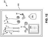
- FIG. 12is a top view of an exemplary medical procedure kit which may be used for delivering electrical stimulation to a target nerve in order to selectively block nerve fiber activity.
- FIG. 13is a side perspective view of an exemplary percutaneous electrode assembly utilized for delivering electrical energy directly to the vicinity of a target nerve to selectively block nerve fiber activity.
- FIGS. 14A and 14Bare side perspective views of exemplary percutaneous electrodes for delivering electrical energy directly to the vicinity of a target nerve to selectively block nerve fiber activity in which an anode and cathode are present on only a portion of the radial surface of the electrode.
- FIG. 15is a side cross-sectional view of an exemplary percutaneous electrode assembly including a lumen or passageway for delivering fluid therethrough, the electrode assembly utilized for delivering electrical energy directly to the vicinity of a target nerve to selectively block nerve fiber activity.
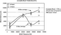
- FIG. 16is a graph showing the effectiveness of various nerve block frequencies on A-fibers and C-fibers, where the nerve block stimulation was delivered via a cuff electrode, as described in Example 1.
- FIG. 17is a graph showing the effectiveness of various nerve block frequencies on A-fibers and C-fibers, where the nerve block stimulation was delivered percutaneously via a probe as described in Example 2.
- A-fiberrefers to myelinated afferent or efferent peripheral axons of the somatic nervous system with conduction velocities between about 2 meter per second (m/s) to more than 100 m/s.
- A-fibershave a diameter of about 1 to 22 micrometers ( ⁇ m) and include the alpha, beta, delta, and gamma fibers.
- Each A-fiberhas dedicated Schwann cells forming the myelin sheath around it.
- the myelin sheathhas a high content of lipids that increases the membrane resistance and contributes to the high conduction velocity of action potentials which are carried from one to the next intersection between two myelin covered segments.
- A-fibersare associated with proprioception, somatic motor function, sensations of touch and pressure and also some limited sensations of pain and temperature.
- carrier frequencyAs used herein, the terms “carrier frequency”, “carrier signal” or “carrier wave” refer to a waveform that has a fixed center frequency that has been modulated (i.e., altered) in a way that its amplitude, frequency, phase or some other property varies. The frequency is measured in Hertz (cycles per second).
- a carrier frequencyis selected to reduce the skin's impedance, helping the modulating frequency to activate neural structures beneath the skin.
- a carrier frequencyis a high frequency waveform.
- C-fiberrefers to non-myelinated peripheral axons of the somatic nervous system with conduction velocities of less than about 2 m/s.
- C-fibershave a diameter of about 0.3 to 1.4 micrometers ( ⁇ m) and include the dorsal root and sympathetic fibers and are primarily associated with sensations like pain and temperature and some limited mechanoreception and reflex responses.
- the term “disposable”refers to a product that is so inexpensive that it may economically be discarded after only a single use. Products that are “disposable” are typically intended for single use.
- the term “single-use”refers to a product that is intended to be used for only once and is not intended to be re-used, re-conditioned, restored or repaired after that use. These products offer advantages in clinical settings by reducing the potential for contamination or infection. In addition, these products can enhance work flow since they are not collected and assembled for reprocessing and reuse.
- electrical stimulation sufficient to block nerve signal transmissionor “electrical nerve-blocking stimulation” or “electrical nerve-block” refer to electrical energy in a waveform that, upon reaching an axon of a neuron, blocks the propagation of action potentials through the stimulation site.
- the term “intact skin”refers to skin that is sound, unbroken and uninjured, or not altered in any meaningful way such as, for example, by fresh surgical incision, fresh piercing by an instrument such as a needle, trocar or the like.
- modulating frequencyAs used herein, the terms “modulating frequency”, “modulating signal” or “modulating wave” refer to a low to moderate frequency waveform that is used to block neural transduction. For purposes of the present invention, a modulating frequency is selected to provide electrical nerve blocking stimulation to block nerve signal transmission in an effective and safe manner.
- the term “nerve block”refers to an interrupting, hindering or preventing the passage of impulses along a neuron's axon within a nerve.
- the termalso encompasses a form of regional anesthesia in which insensibility is produced in a part of the body by interrupting, hindering or preventing the passage of impulses along a neuron's axon, making the nerve inoperable.
- the terms “nerve cuff”, “nerve collar” and/or “nerve hook”refer to electrode assemblies providing electrical interfaces with nerve fibers for applying or electrical energy or monitoring neural activity.
- Exemplary nerve cuffsare described at, for example, Journal of Neuroscience Methods 64 (1996) 95-103 “Cuff Electrodes For Chronic Stimulation and Recording of Peripheral Nerve Activity”; Loeb, G. E., Peck, R. A.
- Nerve cuffsmay be spiral wound and have one or more electrodes arrayed radially or axially and may be shielded to isolate the electrodes from background electrical signals.
- Other exemplary nerve cuff devicesare described at, for example, U.S. Pat. No. 5,344,438 issued Sep. 6, 1994 to Testerman et al. for “Cuff Electrode”.
- percutaneousand/or “percutaneously” refer to electrical stimulation applied utilizing one or more electrodes penetrating through the surface of the skin so an electrode delivering electrical stimulation to a target nerve beneath the skin is also located beneath the skin. It is contemplated that return electrodes or anodes may be located beneath the skin or on the surface of the skin.
- percutaneous electroderefers to electrode assemblies inserted through the skin and directed into the vicinity of the nerve (mm to cm distance) in a minimally invasive fashion to electrically affect neural physiology.
- pain sensationor “painful sensation” refer to a highly disagreeable sensation generated by the activation of sensory nociceptors. Nociception describes the perception of acute pain.
- target nerverefers to mixed nerves containing motor nerve fibers and sensory nerve fibers. It may additionally refer to sensory nerves containing only sensory nerve fibers and/or to motor nerves containing only motor nerve fibers.
- transcutaneousand/or “transcutaneously” refer to electrical stimulation applied non-invasively utilizing one or more electrodes applied to the surface of the skin so the electrical stimulation passes through the skin.
- the electrical stimulationmay be delivered to the target nerve utilizing an electrode that may be in the form of an electrode assembly that can include a nerve cuff or collar to selectively block nerve fiber activity in a target nerve.
- the electrical stimulationmay be delivered through intact skin to block nerve signal transmission in an underlying target nerve (i.e., delivered in a transcutaneous or transdermal manner) without use of an instrument or electrode that physically penetrates the skin by incision, piercing, or the like to be physically adjacent the target nerve.
- electrical stimulationis delivered directly to intact skin to block nerve signal transmission in an underlying target nerve in a non-invasive manner.
- the intact skinmay be intact mammalian skin.
- the systemincludes multiple devices to control and deliver predetermined electrical pulses at predetermined frequencies and amplitudes to one or more target nerve(s).
- the systemreferenced as the schematic system 10 in FIG. 1 , may include one or more electrode 20 (shown diagrammatically in FIG. 1 and not in any specific detail) that is connected by an electrical lead “L” to the rest of the system 10 —which includes a pulse generator 30 , a user interface 40 , and a controller 50 .
- the systemmay also include a patient monitor system 60 and an isolated power system 80 . While an experimental-scale system is shown and described, it is contemplated that a more compact unit could be used to control and deliver the desired electrical stimulation.
- an exemplary electrode 20 for delivering electrical energy directly to a target nervethe electrode 20 is in the form of an electrode assembly 302 that includes a nerve cuff or collar 304 having a stimulating electrode 306 and a blocking electrode 308 located on the cuff to contact the target nerve orthodromic to the stimulating electrode 306 .
- Each electrodehas an anode region 310 for contacting the target nerve “N” and a cathode region 312 for contacting the target nerve “N”.
- the arrow “A”represents the orthodromic direction for this exemplary nerve “N”.
- FIG. 4is a side perspective view illustration of an exemplary electrode assembly 302 that includes the nerve cuff or collar 304 of FIG. 2 positioned in contact with an exemplary target nerve “N”. As can be seen in FIG. 4 , the simulating electrode 306 and the blocking electrode 308 are in contact with the target nerve “N”.
- the electrode 20is in the form of a percutaneous blocking electrode(s) 502 that is placed nearby a target nerve.
- Each blocking electrode 502 used in a bipolar or multi-polar fashionhas an anode 504 and a cathode 506 placed nearby a target nerve “N”.
- Monopolar percutaneous blocking electrodeshave a cathode 506 located nearby a nerve, and a return electrode (i.e., anode) positioned some distance away (e.g., in the form of a patch electrode on the surface of the skin).
- Bipolar and multipolar electrode configurationshave at least one cathode and one anode in the vicinity of the nerve.
- the electrode shape and size, and inter-electrode spacingare specific to contouring the electrical field surrounding the nerve, to enable selective high frequency blocking.
- a suitable multipolar electrodemay include a center cathode electrode 506 that is flanked by two anodes 504 , where the anodal electrodes are connected together, effectively sharing a charge.
- the electrodesmay be circumferential in shape (e.g., disposed radially at the surface of the electrode) and have a diameter ranging from 0.25 mm to 10 mm, and a width from 0.25 mm to 10 mm.
- the electrodesmay have a diameter ranging from about 0.25 mm to 5 mm, and a width from 0.25 mm to 5 mm.
- the electrodesmay have a diameter ranging from about 0.25 mm to 3 mm, and a width from 0.25 mm to 3 mm.
- the inter-electrode spacingmay have a range from 0.5 mm to 10 mm.
- the electrodesmay have varying impedances, to better contour the electric field that will block the nerve.
- FIG. 14Athere is illustrated a side perspective view of an exemplary percutaneous electrode 502 for delivering electrical energy directly to the vicinity of a target nerve to selectively block nerve fiber activity and in which an anode 504 and cathode 506 are present on only a portion of the radial surface of the electrode assembly.
- shielding 508covers portions of the anode 504 and cathode 506 so the anode and cathode are present on only a portion of the radial surface of the electrode assembly.
- FIG. 14Billustrates anodes 504 and a cathode 506 in the form of small plates or tabs 512 located on the radial surface 510 of the percutaneous electrode 502 . While FIG. 14A illustrates an exemplary percutaneous electrode in multipolar configuration, the electrode may have a bipolar or monopolar configuration.
- FIG. 15is a side cross-sectional view of an exemplary percutaneous electrode 502 including a lumen or passageway 512 for delivering fluid therethrough.
- the percutaneous electrode 502may define a lumen or passageway 512 through the electrode to channel a fluid through the electrode and may further define openings 514 in communication with the lumen or passageway 512 to deliver fluid out through the electrode.
- the electrode assemblydefines openings 514 adjacent the anode 504 and cathode 506 . However, these openings 514 may be at other locations.
- the lumen or pathway 512may be integrated with or connected to a tube to deliver fluid to the lumen.
- the delivery tubecan have a standard Luer connection or similar connection.
- the electrode assemblymay be connected to a fluid flow path in communication with a fluid pump; the fluid flow path may be configured to deliver a fluid to be dispensed to a patient through the electrode assembly.
- the electrode assemblymay be connected to a bolus reservoir in communication with a bolus flow path.
- the bolus reservoirmay be configured to selectively permit fluid to be dispensed to a patient through the electrode assembly.
- the arrangementmay include a patient operable actuator configured to dispense fluid from the bolus reservoir.
- the percutaneous electrodecan be used to deliver medicinal fluid such as liquid anesthetic in addition to nerve blocking electrical stimulation.
- the medicinal liquidmay be a bolus of anesthetic or it may be an antibiotic material, antimicrobial material or an electrolytic solution to enhance delivery of electrical stimulation.
- Exemplary fluid pumps, fluid flow paths and bolus delivery configurations or systemsare described in U.S. Pat. No. 6,981,967 issued Jan. 3, 2006 to Massengale et al., for “Large Volume Bolus Device and Method”, incorporated herein by reference.
- the one or more electrodes 20may be a transcutaneous electrode 21 .
- a transcutaneous electrode 21placed in contact with the surface “S” of the skin “SK” above a target nerve “N”.
- the separation between the surface “S” of the skin and the target nerve “N”is identified as distance “D”.
- the distance “D”is on the order of millimeters, where larger distances require more intensive stimulation to achieve a nerve block. Mild amounts of pressure may be applied to the transcutaneous electrode to decrease the electrode-skin distance, reducing the effective stimulation intensity and improve subject comfort.
- the overall shape of the one or more exemplary transcutaneous electrodes 21is such that it allows an operator to precisely place the electrode tip in the proximity of a targeted nerve.
- the electrodesmay include an elongated shaft 22 having a tip 24 defining a generally uniform skin contacting surface 26 one end, and a support such as a handle 28 at the opposite end.
- An electrical lead “L”may be integrated with the electrode 20 or may be attached using a conventional electrical connector.
- the skin contacting surface 26 of the tip 24is an electrically conductive surface.
- the transcutaneous electrode 21is constructed from a metal that is conductive and biocompatible, such as stainless steel.
- the handle 28if used, may be large enough for a clinician to comfortably grip, and may be made of material that will minimize the risk of accidental shock, e.g., non-conductive plastic.
- the transcutaneous electrode 21is electrically connected to a pulse generator 30 by way of an electrical lead or lead-wire.
- the tip 24desirably has a blunt end, desirably spherical, spheroidal, hemi-spherical or hemi-spheroidal in shape.
- the shaft diameterfor a distance of at least about one inch from the tip, is less than or equal to the tip diameter.
- One possible electrode that meets such criteriais the pedicle screw probe electrode, model PSP-1000, available from Axon Systems, Inc. However, other electrode configurations are contemplated.
- the transcutaneous electrodes 21may desirably define a generally uniform skin contacting surface 26 .
- the skin contacting surface of each transcutaneous electrodehas an area of from about 1.5 mm 2 to about 100 mm 2 .
- the skin contacting surfacehas an area of from about 3.5 mm 2 to about 20 mm 2 .
- the tip of the electrodemay have an oval, elliptical or circular cross-section.
- the tip 24 of the transcutaneous electrode 21is circular and may be less than 7 mm in diameter; or less than 5 mm in diameter, or most desirably is about 2.5 mm diameter.
- a smaller electrodeis less likely to activate the skin's pain receptors and is more controllable so it is easier to position the electrode an adequate distance from superficial muscle groups and non-target nerves.
- the shaft 22may be coated with TEFLON® fluoropolymer or other conventional insulating material to create a higher field density at the tip.
- the relatively small tip 24corresponds to a relatively large current density of about 942 mA/cm 2 (20 mA peak current; 1.5 mm 2 surface area), to 1 mA/cm 2 and most desirably, 140 mA/cm 2 (calculated with a 2.5 mm tip diameter; square-wave pulses; 50% duty cycle).
- FIG. 7is an illustration of an exemplary electrode tip 24 extending from the shaft 22 of the electrode.
- the electrode tip 24has a generally spherical shape to provide a generally uniform skin contacting surface 26 .
- FIG. 8is an illustration of another exemplary electrode tip 24 extending from the shaft 22 of the electrode.
- the electrode tip 24has a generally spheroidal shape (e.g., an oblate spheroid) to provide a generally uniform skin contacting surface 26 .
- FIG. 9is an illustration of yet another exemplary electrode tip 24 extending from the shaft 22 of the electrode.
- the electrode tip 24has a generally hemi-spherical shape to provide a generally uniform skin contacting surface 26 .
- the electrode tip 24has a generally hemi-spheroidal shape (e.g., about one-half of an oblate spheroid) to provide a generally uniform skin contacting surface 26 .
- a generally hemi-spheroidal shapee.g., about one-half of an oblate spheroid
- a variety of other shapes and configurationsmay be utilized.
- the electrode shaft 22may be truncated to the tip 24 or near the tip (leaving only a small portion of shaft 22 ) and attached or otherwise connected to a holding device 100 that can securely position the transcutaneous electrode 21 over the targeted nerve during the stimulation procedure.
- FIG. 11shows one example of a holding device 100 to which a transcutaneous electrode 21 is placed.
- the transcutaneous electrode 21has a shaft 22 and a tip 24 and may be connected to a pulse generator 30 through an electrical lead “L”.
- An optional second transcutaneous electrode 21 ′may also be incorporated with the holding device 100 .
- the optional second electrode 21 ′may be an additional electrode or it may be an anode.
- the optional second electrode 21 ′has a shaft 22 ′ and a tip 24 ′ and may be connected to a pulse generator 30 through an electrical lead “L′”. It is contemplated that additional electrodes in the form of transcutaneous electrodes and/or anodes may be utilized.
- the holding devicemay have a strap 102 such as illustrated in FIG. 11 .
- the strap 102may have fastening components 104 such as, for example, cohesive materials or mechanical fasteners (e.g., hook and loop systems, clips, snaps, pins, etc.).
- the electrode ensemblemay deliver stimulation in monopolar fashion or mode.
- one or more stimulating electrode(s)is positioned over the target nerve and a second dispersive electrode with a relatively larger surface area is positioned on a surface of the patient's body to complete the circuit.
- the stimulationmay be delivered in a bipolar fashion or mode and the above-described system may further include one or more anodes, each anode having a skin contacting surface.
- the one or more electrode(s)(also referred to as a “cathode(s)” is positioned over the target nerve and one or more anode(s) is positioned on the skin over the target nerve to preferentially concentrate the delivery of electrical energy between the cathode(s) and anode(s).
- the electrodesshould be positioned a sufficient distance away from each other, to avoid shunting and a possible short-circuit.
- the skin contacting surface of each anodewill desirably have at least the same or greater surface area as the skin contacting surface of the stimulating electrode(s).
- the electrodes 20 or 21may be connected to a pulse generator 30 through an electrical lead “L”.
- the pulse generator 30is a bipolar constant current stimulator.
- One exemplary stimulatoris the DIGITIMER DS5 peripheral electrical stimulator available from Digitimer Ltd., England.
- Other constant current and constant voltage pulse generatorsmay be used.
- Exemplary generatorsmay include Model S88x, S48, or SD9 Stimulators available from Grass Technologies, a subsidiary of Astro-Med, Inc., West Warwick, R.I., USA.
- Monopolar stimulationmay also be used to block neural transduction, although the stimulation may be less effective.
- the systemmay utilize a user interface 40 .
- This user interface 40may be in the form of a computer that interacts with the controller 50 and is powered by an isolation system 80 , each described herein.
- the computeroperates software designed to record signals passed from the controller, and to drive the controller's output.
- Possible softwareincludes Cambridge Electronic Design's (UK) SPIKE program.
- the softwareis programmable and can record and analyze electrophysiological signals, as well as direct the controller to deliver stimulation.
- An optional patient monitor system 60may be used.
- the patient monitoring systemacquires, amplifies and filters physiological signals, and outputs them to the controller.
- the optional monitoring systemincludes a heart-rate monitor 62 to collect electrocardiogram signals, and muscle activity monitor 64 to collect electromyography signals.
- the heart-rate monitor 62includes ECG electrodes 68 coupled with an alternating current (AC) amplifier 70 A.
- the muscle activity monitor 64includes EMG electrodes 72 coupled with an AC amplifier 70 B.
- AC signal amplifier/conditioner70 A, 70 B.
- One possible amplifier/conditioneris Model LP511 AC amplifier available from Grass Technologies, a subsidiary of Astro-Med, Inc., West Warwick, R.I., USA.
- All instrumentsare powered by an isolated power supply or system 80 to protect them from ground faults and power spikes carried by the electrical main.
- An exemplary isolated power systemis available is the Model IPS115 Isolated Medical-grade Power System from Grass Technologies, a subsidiary of Astro-Med, Inc., West Warwick, R.I., USA.
- a controller 50records waveform data and digital information from the patient monitor system 60 , and can generate waveform and digital outputs simultaneously for real-time control of the pulse generator 30 .
- the controller 50may have onboard memory to facilitate high speed data capture, independent waveform sample rates and on-line analysis.
- An exemplary controller 50may be a POWER 1401 data-acquisition interface unit available from Cambridge Electronic Design (UK).
- FIG. 12is meant to depict a kit 200 that includes any manner of suitable container 202 in which is provided any combination of the components depicted in FIGS. 1 through 11 . It should be appreciated that the kit 200 need not contain all of the articles depicted in FIGS. 1 through 11 . That is, components such as controller, pulse generator, user interface, patient monitoring system, amplifiers or the like need not be included—although suitable electrodes such as the ECG and EMG electrodes may be included in the kit.
- the container 202may be, for example, a suitable tray having a removable sealed covering in which the articles are contained.
- an embodiment of the kit 200may include the container 202 with one or more electrodes 20 (e.g., transcutaneous electrodes 21 are shown but percutaneous electrodes and/or nerve cuff electrodes may be contained in the kit) and electrical leads “L” as discussed above.
- the kitmay further include one or more anodes. Each anode desirably has a skin contacting surface that has at least the same (or greater) surface area as the skin contacting surface of the stimulating electrode.
- kits 200with any combination of the items utilized to perform the procedure of delivering electrical stimulation utilizing percutaneous electrodes described herein, utilizing nerve cuffs described here, or utilizing transcutaneous electrodes described herein.
- a kit 200may include additional items, such as ECG electrodes 68 and EMG electrodes 72 , as well as any combination of a drape, site dressings, tape, skin-markers and so forth.
- the kit 200may include one or more containers 204 of electrically conductive liquids or gels, antiseptics, or skin-prep liquids.
- the kit 200may include pre-packaged wipes 206 such as electrically conductive liquid or gel wipes, antiseptic wipes, or skin-prep wipes.
- the kitmay contain medicinal liquids and/or electrolytic solutions.
- the electrolytic solutionmay be or may include a bioresorbable gel material that is injected in liquid form but becomes substantially viscous or even solid-like after exiting the openings in the percutaneous electrode.
- the present inventionalso encompasses a method for selectively blocking nerve fiber activity in a target nerve.
- the methodinvolves the steps of: locating a target nerve; positioning one or more electrodes on the skin over the target nerve, through the skin near the target nerve, or through the skin and directly on or around the nerve using the electrode assembly (e.g., including a nerve cuff or collar or a probe); and delivering electrical stimulation to the target nerve at a frequency greater than about 30 kilohertz to block nerve signal transmission of C-fibers in the target nerve such that the nerve signal transmission of the A-fibers in the target nerve providing motor function and/or low-threshold sensory function is not blocked.
- the electrode assemblye.g., including a nerve cuff or collar or a probe
- the methodmay rely on a patient's (e.g., the user) feedback of pain during delivery of nerve blocking stimulation to assess the effectiveness of the selective nerve block.
- the methodmay rely on feedback collected by a recording electrode, such as the exemplary recording electrode described above, and/or electromyogram signals to assess the effectiveness of the selective nerve block.
- the step of delivering electrical stimulation to the target nerveinvolves first delivering electrical stimulation to the target nerve to block nerve signal transmission of both A-fibers and C-fibers in the target nerve and then reducing the amplitude of the electrical stimulation (desirably, while maintaining or increasing the frequency of the electrical stimulation) so nerve signal transmission of the C-fibers in the target nerve is blocked and so the nerve signal transmission of the A-fibers in the target nerve providing motor function and/or low-threshold sensory function is not blocked.
- the electrical nerve-blocking stimulationmay be high-frequency simulation, low-frequency stimulation and moderate-frequency stimulation, and combinations thereof depending on the specific nerve fiber activity to be blocked.
- the electrical nerve-blocking stimulation frequencyis desirably greater than 30 kHz (e.g., from about 30 kHz to about 100 kHz), desirably less than about 25 milliamps for transcutaneous stimulation and less than about 10 milliamps for stimulation directly in the vicinity of the nerve, and is an alternating current that may be selected from sinusoidal, square-wave pulses, and a pulse train that varies in amplitude and frequency within the identified parameters (e.g., greater than 30 kHz and less than 25 mA or 10 mA).
- the electrical nerve-blocking stimulationmay further include a carrier frequency that is greater than the stimulating frequency and the carrier frequency may range from about 100 kHz to about 1 MHz; desirably from 200 kHz to about 1 MHz.
- the methodinvolves the steps of: locating a target nerve; positioning one or more stimulating electrodes on the skin over the target nerve or directly on or around the nerve; and delivering electrical nerve-blocking stimulation to the target nerve to block nerve signal transmission of A-fibers in the target nerve providing motor function and/or low-threshold sensory function is blocked and so that the nerve signal transmission of the C-fibers in the target nerve is not blocked.
- the methodmay rely on a patient's (e.g., the user) feedback of motor function and/or low-threshold sensory function during delivery of nerve blocking stimulation to assess the effectiveness of the selective nerve block.
- the methodmay rely on feedback collected by a recording electrode, such as the exemplary recording electrode described above, and/or electromyogram signals to assess the effectiveness of the selective nerve block.
- the step of delivering electrical nerve-blocking stimulation to the target nerveinvolves first delivering electrical nerve-blocking stimulation to the target nerve at a frequency to block nerve signal transmission of both A-fibers and C-fibers in the target nerve and then reducing the frequency of the electrical nerve-blocking stimulation so nerve signal transmission of the A-fibers in the target nerve providing motor function and/or low-threshold sensory function is blocked and so the nerve signal transmission of the C-fibers in the target nerve is not blocked.
- the electrical nerve-blocking stimulation frequencyis desirably less than 30 kHz (e.g., from less than about 30 kHz down to about 5 kHz), and the amplitude is desirably less than about 25 milliamps for transcutaneous stimulation and less than about 10 milliamps for stimulation directly in the vicinity of the nerve (e.g., from less than about 25 mA or 10 mA down to about 0.5 mA or even lower).
- the nerve blocking stimulationis desirably an alternating current that may be selected from sinusoidal, square-wave pulses, and a pulse train that varies in amplitude and frequency within the identified parameters (e.g., less than 30 kHz and less than 25 mA or 10 mA—depending on whether stimulation is transcutaneous or directly in the vicinity of the nerve).
- the electrical nerve-blocking stimulationmay further include a carrier frequency that is greater than the stimulating frequency and the carrier frequency may range from about 100 kHz to about 1 MHz; desirably from 200 kHz to about 1 MHz.
- each anodedesirably has a skin contacting surface such that the skin contacting surface of the anode has at least the same (or greater) surface area as the skin contacting surface of the stimulating electrode.
- one or more anodesare positioned on the skin over the target nerve and a distance away from one or more stimulating electrodes sufficient to avoid shunting.
- the use of current regulated stimulihas an advantage over voltage regulated stimuli in the transcutaneous method of the invention because the current density is better controlled.
- the method of practicing the present inventionmay further include the use of coupling media such as, for example, an electrically conductive liquid, gel or paste that may be applied to the skin to enhance the conductivity of the skin and/or lower impedance.
- coupling mediasuch as, for example, an electrically conductive liquid, gel or paste that may be applied to the skin to enhance the conductivity of the skin and/or lower impedance.
- one or more skin moisturizers, humectants or the likemay be applied to the skin for the purpose of enhancing the conductivity of the skin and/or lowering impedance of the skin.
- Examples of conductive pastesinclude Ten20TM conductive paste from Weaver and Company, Aurora, Colo., and ELEFIX Conductive Paste from Nihon Kohden with offices at Foothill Collins, Calif.
- conductive gelsinclude Spectra 360 Electrode Gel from Parker Laboratories, Inc., Fairfield, N.J. or Electro-Gel from Electro-Cap International, Inc., Eaton, Ohio.
- a complete blockwas defined as a greater than 75% decrease of burst area compared to pre-block conditions.
- nerve block stimulation frequenciesof about 30,000 Hz or greater, such as between about 30,000 Hz and 70,000 Hz, resulted in the selective blocking of C-fibers with less stimulation intensity than the A-fibers, such as between about 2000 and 7000 microAmps.
- Electromyography signalswere recorded unilaterally from the biceps femoris muscle with insulated and braided 13 millimeter (mm) sub-dermal needle electrodes (RhythmLink, SC). Signals were passed through a nearby headstage, bandpass filtered (500 Hz to 5000 Hz) and amplified (500 ⁇ ; LP511, Grass Technologies, RI), and sent to a data acquisition system (Power3 1401, Cambridge Electronic Design, UK) for digitization.
- EMGElectromyography signals
- Constant-voltage, monophasic square-wave pulses(2.5 millisecond pulse duration; 0.15 Hz) were delivered at intensities sufficient to cause a brisk plantar-going twitch without causing neural windup (30 V to 150 V).
- a tripolar electrodewas placed percutaneously onto the sural nerve located in the lower shank.
- the center electrode(2 mm width) was considered to be cathodic at stimulation onset, and was flanked by 2 anodes (each anode was 2 mm width).
- the electrodeswere made from platinum, and their inter-electrode spacing was 3 mm.
- the blockwas composed of a constant-current, charge-balanced sinusoidal stimulation delivered at various frequencies (10, 45, 51 and 61 kHz). The blocking intensities were varied during the study ( ⁇ 30 milliAmps).
- CMAPcompound muscle action potentials
- Each trialwas split into four 30 second epochs.
- the acquired data tracingswere modified to approximate a leaky integrator (DC-Offset; full-wave rectified, smoothed).
- Spike2(Version 8.1; Cambridge Electronic Design, UK) software was used for data processing.
- the area beneath the resulting EMG contour(aka: neurogram) was calculated for each electrical stimulation delivered during the trial.
- the sensory fiber activation typeswere differentiated by time post-stimulation: activation of A-fibers and C-fibers occurred between 4.5 to 45 milliseconds and 80 to 450 milliseconds post-stimulation, respectively.
- the areas collected during trial epochs 2-4were compared to those collected pre-block (epoch 1).
- FIG. 17shows the average Compound CMAP areas collected during complete block of the C-fibers.
- the bar graphdemonstrates that a percutaneous block delivered at 45 KHz, 51 KHz and 60 KHz disrupts the transmission of action potentials along C-fibers more than potentials carried by A-fibers.
- the blockattenuated A-fiber activity by 40%, and C-fiber activity by 80%.
- Blocks delivered at 10 KHzdid not demonstrate selective blocking.
- Motor-thresholds collected before (Average: 1.5 V; Range: 1.3 to 1.7 V) and after (Average: 1.4; Range: 1.2 V to 2 V) delivery of the various blocking trialssuggest that the nerve was not damaged during testing.
- Example 2the effect of the position and orientation of the percutaneous electrode utilized in Example 2 on the ability to selectively nerve block A-fibers and C-fibers was demonstrated.
- Table 1when the uninsulated portion of the percutaneous electrode was placed directly on top of the nerve to be blocked and a 10.8 milliAmp intensity stimulation was applied at 51 kHz, the A-fibers and C-fibers were blocked, as evidenced by a decrease in nerve signal transmission from full (100%) transmission to 18.30% for the A-fibers and 7.54% for the C-fibers for the first block, and to 23.03% for the A-fibers and 6.57% for the C-fibers for the second block.
- Example 3demonstrates the importance of minimizing movement or migration of the percutaneous electrode, where the noninsulated, active portion of the electrode should be in contact with the nerve to be blocked to facilitate effective blocking.
Landscapes
- Health & Medical Sciences (AREA)
- Life Sciences & Earth Sciences (AREA)
- Veterinary Medicine (AREA)
- Animal Behavior & Ethology (AREA)
- Neurology (AREA)
- Engineering & Computer Science (AREA)
- Biomedical Technology (AREA)
- Nuclear Medicine, Radiotherapy & Molecular Imaging (AREA)
- Radiology & Medical Imaging (AREA)
- Public Health (AREA)
- General Health & Medical Sciences (AREA)
- Neurosurgery (AREA)
- Heart & Thoracic Surgery (AREA)
- Pain & Pain Management (AREA)
- Orthopedic Medicine & Surgery (AREA)
- Cardiology (AREA)
- Biophysics (AREA)
- Electrotherapy Devices (AREA)
Abstract
Description
- 1. Stimulation type: Constant-current, or constant-voltage stimulation
- 2. Delivery fashion: may be monophasic or biphasic (most desirable for blocking)
- 3. Waveform: square-wave; sinusoidal; pulse train
- 4. Pulse frequency: in order to selectively block A-fibers with the least amount of stimulation intensity, the pulse frequency may be about 0.1 Hz (i.e., above 0 hertz) to about 30 kHz, desirably 3 kHz to about 30 kHz, and more desirably 5 kHz to about 30 kHz. In order to block C-fibers with the least amount of stimulation intensity, the pulse frequency may be about 30 kHz (i.e., above 30 kilohertz) to about 100 kHz, desirably 30 kHz to about 75 kHz, and more desirably 40 kHz to 60 KHz.
- 5. Pulse duration: may be less than about 1000 μs; or less than about 5 μs; or most desirably 10 ρs for conduction blocking
- 6. Phase duration: (for biphasic pulses only) may be less than about 500 μs; or less than about 2.5 μs; or most desirably 5 μs for conduction blocking
- 7. Current: may be about 0.1 mA (i.e., above 0 mA) to about 25 mA. Generally speaking, when electrical stimulation is applied directly in the vicinity of the target nerve (i.e., using an electrode assembly that includes a nerve cuff, collar or a probe), the current should be less than about 10 mA. When the current is applied percutaneously or transcutaneously (i.e., through the intact skin), the current should be less than about 25 mA.
- 8. Current density (for Transcutaneous Electrode only): less than 942 mA/cm2. The current density of the ideal stimulation for blocking with a hemispherical, 2.5 mm diameter electrode tip may be about 280 mA/cm2, and most desirably, about 140 mA/cm2.
- 9. Pulse period: (the amount of time between the start of one pulse to the start of the next pulse; it includes phase duration, intrapulse intervals, and interpulse intervals) may be less than about 1 millisecond (ms); or 0 ms, or most desirably about 0.02 ms for conduction blocking.
- 10. Pulse train: (burst of multiple pulses) may be delivered on the order of seconds to minutes. Each pulse train is separated by an off-time which is the interburst interval (variable, patient specific).
High-Frequency Stimulation - 1. Stimulation type: Constant-current, or constant-voltage stimulation
- 2. Delivery fashion: may be monophasic or biphasic (most desirable)
- 3. Waveform: square-wave; sinusoidal; pulse train
- 4. Pulse frequency: may be about 30 kHz to 1 MHz; desirably 45 kHz to 1 MHz
- 5. Pulse duration: may be less than about 5 μs; or less than 0.5 μs; or most desirably 2.5 μs
- 6. Phase duration: (for biphasic pulses only) may be less than about 2.5 μs; or less than 0.25 μs; or most desirably 1.25 μs for each portion of the pulse.
- 7. Current: may be about 0.1 mA (i.e., above 0 mA) to 25 mA. Generally speaking, when electrical stimulation is applied directly in the vicinity of the target nerve (i.e., using an electrode assembly that includes a nerve cuff, collar or a probe), the current should be less than about 10 mA. When the current is applied transcutaneously (i.e., through the intact skin), the current should be less than about 25 mA.
- 8. Current density (for Transcutaneous Electrode only): (amount of current (mA) per unit area (cm2) for a hemispherical, 2.5 mm diameter, electrode tip) may be less than about 70 mA/cm2, and most desirably about 10 mA/cm2.
- 9. Pulse train: (burst of multiple pulses) may be delivered on the order of milliseconds to seconds. Each pulse train is separated by an off time which is the interburst interval (variable, patient specific).
- 10. Pulse period: (the amount of time between the start of one pulse to the start of the next pulse; it includes phase duration, intrapulse intervals, and interpulse intervals) may be less than about 10 μs; or more than about 1 μs; or most desirably about 5 μs.
- 1. Setup stimulation system near a stable patient bed.
- 2. Place patient into a comfortable supine position.
- 3. Place the optional ECG and EMG on patient.
- 4. Begin monitoring heart-rate and EMG.
- 5. Locate the target nerve, either by utilizing a nerve locator (e.g., Ambu® Ministim® nerve stimulator & locator), or by passing low-levels of stimulation through the stimulator that is used for blocking. A stimulus-elicited muscle twitch in a distal muscle group with low-stimulation amplitudes (single pulse) will indicate that your stimulation point is proximal enough for blocking.
- 6. Position the tip of the blocking electrode in the vicinity of the nerve (or overtop of the nerve and press it gently towards the skin, decreasing the distance between the electrode and target nerve, and assuring good contact between the electrode and skin). Maintain the stimulation electrode in this position.
- 7. Apply electrical stimulation to the subject using the stimulating parameters described herein to selectively block nerve signal transmission in the target nerve. If a carrier signal is to be used, then determine the optimal carrier signal before blocking the nerve.
| TABLE 1 |
| Importance of Percutaneous Electrode Position and Orientation |
| Uninsulated Portion of Electrode Placed Directly on Top of Nerve |
| Time | A-Fiber Activity | C-Fiber Activity | ||
| Stimulation Intensity | Interval | (%) | (%) | |
| 10.8 milliAmps | Pre-Block | 100.00 | 100.00 | |
| (Peak to Peak) | Block 1 | 18.30 | 7.54 | |
| 51 | Block | 2 | 23.03 | 6.57 |
| Post-Block | 110.33 | 117.11 | ||
| Uninsulated Portion of Electrode Turned 180° Away from Nerve |
| Time | A-Fiber Activity | C-Fiber Activity | ||
| Stimulation Intensity | Interval | (%) | (%) | |
| 11.5 milliAmps | Pre-Block | 100.00 | 100.00 | |
| (Peak to Peak) | Block 1 | 88.57 | 101.32 | |
| 51 | Block | 2 | 97.24 | 88.54 |
| Post-Block | 97.07 | 114.04 | ||
Claims (30)
Priority Applications (1)
| Application Number | Priority Date | Filing Date | Title |
|---|---|---|---|
| US15/501,450US11464971B2 (en) | 2014-08-26 | 2015-08-24 | Selective nerve fiber block method and system |
Applications Claiming Priority (3)
| Application Number | Priority Date | Filing Date | Title |
|---|---|---|---|
| US201462041774P | 2014-08-26 | 2014-08-26 | |
| PCT/US2015/046482WO2016032929A2 (en) | 2014-08-26 | 2015-08-24 | Selective nerve fiber block method and system |
| US15/501,450US11464971B2 (en) | 2014-08-26 | 2015-08-24 | Selective nerve fiber block method and system |
Publications (2)
| Publication Number | Publication Date |
|---|---|
| US20170224989A1 US20170224989A1 (en) | 2017-08-10 |
| US11464971B2true US11464971B2 (en) | 2022-10-11 |
Family
ID=54012337
Family Applications (1)
| Application Number | Title | Priority Date | Filing Date |
|---|---|---|---|
| US15/501,450ActiveUS11464971B2 (en) | 2014-08-26 | 2015-08-24 | Selective nerve fiber block method and system |
Country Status (11)
| Country | Link |
|---|---|
| US (1) | US11464971B2 (en) |
| EP (1) | EP3185951A2 (en) |
| JP (1) | JP6902464B2 (en) |
| KR (1) | KR20170047300A (en) |
| CN (2) | CN106714898A (en) |
| AU (1) | AU2015306890B2 (en) |
| BR (1) | BR112017004047A2 (en) |
| CA (1) | CA2959330C (en) |
| MX (1) | MX370944B (en) |
| RU (1) | RU2017105405A (en) |
| WO (1) | WO2016032929A2 (en) |
Cited By (32)
| Publication number | Priority date | Publication date | Assignee | Title |
|---|---|---|---|---|
| US11864728B2 (en) | 2017-12-28 | 2024-01-09 | Cilag Gmbh International | Characterization of tissue irregularities through the use of mono-chromatic light refractivity |
| US11896322B2 (en) | 2017-12-28 | 2024-02-13 | Cilag Gmbh International | Sensing the patient position and contact utilizing the mono-polar return pad electrode to provide situational awareness to the hub |
| US11903601B2 (en) | 2017-12-28 | 2024-02-20 | Cilag Gmbh International | Surgical instrument comprising a plurality of drive systems |
| US11918302B2 (en) | 2017-12-28 | 2024-03-05 | Cilag Gmbh International | Sterile field interactive control displays |
| US11925373B2 (en) | 2017-10-30 | 2024-03-12 | Cilag Gmbh International | Surgical suturing instrument comprising a non-circular needle |
| US11925350B2 (en) | 2019-02-19 | 2024-03-12 | Cilag Gmbh International | Method for providing an authentication lockout in a surgical stapler with a replaceable cartridge |
| US11969216B2 (en) | 2017-12-28 | 2024-04-30 | Cilag Gmbh International | Surgical network recommendations from real time analysis of procedure variables against a baseline highlighting differences from the optimal solution |
| US11969142B2 (en) | 2017-12-28 | 2024-04-30 | Cilag Gmbh International | Method of compressing tissue within a stapling device and simultaneously displaying the location of the tissue within the jaws |
| US11986233B2 (en) | 2018-03-08 | 2024-05-21 | Cilag Gmbh International | Adjustment of complex impedance to compensate for lost power in an articulating ultrasonic device |
| US11998193B2 (en) | 2017-12-28 | 2024-06-04 | Cilag Gmbh International | Method for usage of the shroud as an aspect of sensing or controlling a powered surgical device, and a control algorithm to adjust its default operation |
| US12009095B2 (en) | 2017-12-28 | 2024-06-11 | Cilag Gmbh International | Real-time analysis of comprehensive cost of all instrumentation used in surgery utilizing data fluidity to track instruments through stocking and in-house processes |
| US20240221924A1 (en)* | 2022-12-30 | 2024-07-04 | Cilag Gmbh International | Detection of knock-off or counterfeit surgical devices |
| US12029506B2 (en) | 2017-12-28 | 2024-07-09 | Cilag Gmbh International | Method of cloud based data analytics for use with the hub |
| US12035890B2 (en) | 2017-12-28 | 2024-07-16 | Cilag Gmbh International | Method of sensing particulate from smoke evacuated from a patient, adjusting the pump speed based on the sensed information, and communicating the functional parameters of the system to the hub |
| US12035983B2 (en) | 2017-10-30 | 2024-07-16 | Cilag Gmbh International | Method for producing a surgical instrument comprising a smart electrical system |
| US12042207B2 (en) | 2017-12-28 | 2024-07-23 | Cilag Gmbh International | Estimating state of ultrasonic end effector and control system therefor |
| US12048496B2 (en) | 2017-12-28 | 2024-07-30 | Cilag Gmbh International | Adaptive control program updates for surgical hubs |
| US12059169B2 (en) | 2017-12-28 | 2024-08-13 | Cilag Gmbh International | Controlling an ultrasonic surgical instrument according to tissue location |
| US12062442B2 (en) | 2017-12-28 | 2024-08-13 | Cilag Gmbh International | Method for operating surgical instrument systems |
| US12059124B2 (en) | 2017-12-28 | 2024-08-13 | Cilag Gmbh International | Surgical hub spatial awareness to determine devices in operating theater |
| US12133709B2 (en) | 2017-12-28 | 2024-11-05 | Cilag Gmbh International | Communication hub and storage device for storing parameters and status of a surgical device to be shared with cloud based analytics systems |
| US12133773B2 (en) | 2017-12-28 | 2024-11-05 | Cilag Gmbh International | Surgical hub and modular device response adjustment based on situational awareness |
| US12226166B2 (en) | 2017-12-28 | 2025-02-18 | Cilag Gmbh International | Surgical instrument with a sensing array |
| US12226151B2 (en) | 2017-12-28 | 2025-02-18 | Cilag Gmbh International | Capacitive coupled return path pad with separable array elements |
| US12226070B2 (en) | 2012-05-20 | 2025-02-18 | Cilag Gmbh International | System comprising control circuit to determine a property of a fluid at a surgical site |
| US12295674B2 (en) | 2017-12-28 | 2025-05-13 | Cilag Gmbh International | Usage and technique analysis of surgeon / staff performance against a baseline to optimize device utilization and performance for both current and future procedures |
| US12310586B2 (en) | 2017-12-28 | 2025-05-27 | Cilag Gmbh International | Method for adaptive control schemes for surgical network control and interaction |
| US12318152B2 (en) | 2017-12-28 | 2025-06-03 | Cilag Gmbh International | Computer implemented interactive surgical systems |
| US12329467B2 (en) | 2017-10-30 | 2025-06-17 | Cilag Gmbh International | Method of hub communication with surgical instrument systems |
| US12377272B2 (en) | 2018-12-07 | 2025-08-05 | Avent, Inc. | Device and method to selectively and reversibly modulate a nervous system structure to inhibit pain |
| US12396806B2 (en) | 2017-12-28 | 2025-08-26 | Cilag Gmbh International | Adjustment of a surgical device function based on situational awareness |
| US12408974B2 (en) | 2014-12-03 | 2025-09-09 | Medtronic Ireland Manufacturing Unlimited Company | Systems and methods for modulating nerves or other tissue |
Families Citing this family (15)
| Publication number | Priority date | Publication date | Assignee | Title |
|---|---|---|---|---|
| CA2959330C (en) | 2014-08-26 | 2022-12-13 | Avent, Inc. | Selective nerve fiber block method and system |
| US20240157141A1 (en)* | 2015-07-08 | 2024-05-16 | Tivic Health Systems Inc. | Migraine treatment device with adaptive circuit |
| CA3011993C (en) | 2016-01-21 | 2024-05-14 | Cala Health, Inc. | Systems, methods and devices for peripheral neuromodulation for treating diseases related to overactive bladder |
| CA3033662A1 (en)* | 2016-08-25 | 2018-03-01 | Cala Health, Inc. | Systems and methods for treating cardiac dysfunction through peripheral nerve stimulation |
| US11628299B2 (en) | 2016-10-17 | 2023-04-18 | Case Western Reserve University | Subcutaneous direct current nerve conduction block |
| US10792495B2 (en) | 2016-12-01 | 2020-10-06 | Thimble Bioelectronics, Inc. | Neuromodulation device and method for use |
| US12343069B2 (en) | 2017-02-01 | 2025-07-01 | Avent, Inc. | EMG guidance for probe placement, nearby tissue preservation, and lesion confirmation |
| US10603504B2 (en) | 2017-09-08 | 2020-03-31 | Alacrity, Inc. | Methods and apparatus for electrically inducing net macro-current across neuronal cell membranes |
| US11167134B2 (en)* | 2017-12-04 | 2021-11-09 | The Charles Stark Draper Laboratory, Inc. | Integrated circuit design for wireless control of biphasic stimulation in bioelectronic implant |
| US10792496B2 (en) | 2018-03-15 | 2020-10-06 | Avent, Inc. | System and method to percutaneously block painful sensations |
| CN108635668A (en)* | 2018-05-18 | 2018-10-12 | 西安交通大学医学院第二附属医院 | A kind of intelligent blocking system based on high-frequency electrical stimulation |
| EP3623004A1 (en)* | 2018-09-13 | 2020-03-18 | BIOTRONIK SE & Co. KG | Interleaved multi-contact neuromodulation therapy with reduced energy |
| US11612344B2 (en) | 2018-11-02 | 2023-03-28 | Biocircuit Technologies, Inc. | Electrode-based systems and devices for interfacing with biological tissue and related methods |
| JP2020089723A (en)* | 2018-12-07 | 2020-06-11 | アヴェント インコーポレイテッド | Device and method for selectively and reversibly modulating nervous system structure to inhibit perception of pain |
| US11623091B2 (en) | 2019-02-13 | 2023-04-11 | Avent, Inc. | Portable electrical stimulation system and method |
Citations (110)
| Publication number | Priority date | Publication date | Assignee | Title |
|---|---|---|---|---|
| US5344438A (en) | 1993-04-16 | 1994-09-06 | Medtronic, Inc. | Cuff electrode |
| US5755750A (en) | 1995-11-13 | 1998-05-26 | University Of Florida | Method and apparatus for selectively inhibiting activity in nerve fibers |
| US20010032001A1 (en) | 1995-06-07 | 2001-10-18 | Olivier Ricart | Systems and methods for electrosurgical treatment of spinal tissue |
| US6319241B1 (en) | 1998-04-30 | 2001-11-20 | Medtronic, Inc. | Techniques for positioning therapy delivery elements within a spinal cord or a brain |
| US20020120259A1 (en) | 1995-06-07 | 2002-08-29 | Lettice John J. | Methods for targeted electrosurgery on contained herniated discs |
| US20030014047A1 (en) | 1995-06-07 | 2003-01-16 | Jean Woloszko | Apparatus and methods for treating cervical inter-vertebral discs |
| US20030100924A1 (en) | 2001-04-20 | 2003-05-29 | Foreman Robert D. | Cardiac neuromodulation and methods of using same |
| US6602248B1 (en) | 1995-06-07 | 2003-08-05 | Arthro Care Corp. | Methods for repairing damaged intervertebral discs |
| US20030158545A1 (en) | 2000-09-28 | 2003-08-21 | Arthrocare Corporation | Methods and apparatus for treating back pain |
| US20030195602A1 (en) | 2002-04-15 | 2003-10-16 | Neuropace, Inc. | Reinforced sensing and stimulation leads and use in detection systems |
| US20050177202A1 (en) | 2004-02-09 | 2005-08-11 | Classen Ashley M. | Method and apparatus for veterinary RF pain management |
| US20050197678A1 (en)* | 2003-05-11 | 2005-09-08 | Boveja Birinder R. | Method and system for providing therapy for Alzheimer's disease and dementia by providing electrical pulses to vagus nerve(s) |
| US20050288730A1 (en) | 2002-04-08 | 2005-12-29 | Mark Deem | Methods and apparatus for renal neuromodulation |
| US6981967B2 (en) | 2001-06-01 | 2006-01-03 | I-Flow Corporation | Large volume bolus device and method |
| WO2006029257A2 (en) | 2004-09-08 | 2006-03-16 | Spinal Modulation Inc. | Neurostimulation methods and systems |
| US20060184211A1 (en) | 2004-01-22 | 2006-08-17 | Gaunt Robert A | Method of routing electrical current to bodily tissues via implanted passive conductors |
| US20060200121A1 (en) | 2005-03-03 | 2006-09-07 | Mowery Thomas M | Navigable, multi-positional and variable tissue ablation apparatus and methods |
| US20070191915A1 (en) | 2005-03-01 | 2007-08-16 | Ndi Medical, Inc. | Systems and methods for intra-operative stimulation |
| US20080027505A1 (en) | 2006-07-26 | 2008-01-31 | G&L Consulting, Llc | System and method for treatment of headaches |
| US20080071321A1 (en) | 2004-06-10 | 2008-03-20 | Ndi Medical, Inc. | Systems and methods of neuromodulation stimulation for the restoration of sexual function |
| US20080132962A1 (en)* | 2006-12-01 | 2008-06-05 | Diubaldi Anthony | System and method for affecting gatric functions |
| US7389145B2 (en) | 2001-02-20 | 2008-06-17 | Case Western Reserve University | Systems and methods for reversibly blocking nerve activity |
| US20080147155A1 (en) | 2006-12-19 | 2008-06-19 | Quan Emerteq Corp. | Braided Electrical Lead |
| US7403821B2 (en) | 2000-02-17 | 2008-07-22 | Neurodan A/S | Method and implantable systems for neural sensing and nerve stimulation |
| US20080208287A1 (en) | 2007-02-27 | 2008-08-28 | Palermo Francis X | Electrical stimulation device and method for the treatment of neurological disorders |
| US20080294221A1 (en)* | 2001-02-20 | 2008-11-27 | Case Western Reserve University | Action potential conduction prevention |
| WO2009061813A1 (en) | 2007-11-05 | 2009-05-14 | Nevro Corporation | Multi-frequency neural treatments and associated systems and methods |
| US20090149926A1 (en) | 2007-12-05 | 2009-06-11 | Searete Llc, A Limited Liability Corporation Of The State Of Delaware | System for thermal modulation of neural activity |
| US20090259279A1 (en)* | 2002-03-22 | 2009-10-15 | Dobak Iii John D | Splanchnic nerve stimulation for treatment of obesity |
| US20100016929A1 (en) | 2004-01-22 | 2010-01-21 | Arthur Prochazka | Method and system for controlled nerve ablation |
| US20100152808A1 (en)* | 2008-12-05 | 2010-06-17 | Ndi Medical, Llc | Systems and methods to place one or more leads in tissue to electrically stimulate nerves of passage to treat pain |
| US20100191311A1 (en)* | 2009-01-27 | 2010-07-29 | Medtronic, Inc. | High frequency stimulation to block laryngeal stimulation during vagal nerve stimulation |
| US20100274318A1 (en)* | 2009-04-22 | 2010-10-28 | Walker Andre B | Devices for controlling high frequency spinal cord modulation for inhibiting pain, and associated systems and methods, including simplified program selection |
| US20110159748A1 (en) | 2009-12-30 | 2011-06-30 | Lily Lim | Terminal connector assembly for a medical electrical lead |
| US20110224665A1 (en) | 2010-03-11 | 2011-09-15 | Peter Andrew Crosby | Modular stimulator for treatment of back pain, implantable rf ablation system and methods of use |
| US8027718B2 (en) | 2006-03-07 | 2011-09-27 | Mayo Foundation For Medical Education And Research | Regional anesthetic |
| US20110301670A1 (en) | 2010-06-08 | 2011-12-08 | Rainbow Medical Ltd. | Tibial nerve stimulation |
| WO2012021583A1 (en) | 2010-08-10 | 2012-02-16 | Case Western Reserve University | Method to treat pain through electrical stimulation of nerves |
| US20120046715A1 (en)* | 2010-08-18 | 2012-02-23 | Boston Scientific Neuromodulation Corporation | User interface for segmented neurostimulation leads |
| US20120197372A1 (en) | 2009-09-30 | 2012-08-02 | Mayo Foundation For Medical Education And Research | Percutaneous placement of electrodes |
| US20120277823A1 (en)* | 2011-04-29 | 2012-11-01 | Medtronic,Inc. | Dual prophylactic and abortive electrical stimulation |
| US20120290053A1 (en)* | 2011-05-11 | 2012-11-15 | St. Jude Medical, Inc. | Renal nerve stimulation lead, delivery system, and method |
| US20120290031A1 (en) | 2011-04-21 | 2012-11-15 | St. Jude Medical Ab | Medical implantable lead |
| US20120296389A1 (en) | 2011-05-19 | 2012-11-22 | Neuros Medical, Inc. | High-frequency electrical nerve block |
| US20120330218A1 (en) | 2011-06-23 | 2012-12-27 | Kerry Bradley | Method for improving far-field activation in peripheral field nerve stimulation |
| US20130110194A1 (en) | 2011-10-28 | 2013-05-02 | Medtronic, Inc. | Combined High and Low Frequency Stimulation Therapy |
| US20130116752A1 (en) | 2011-11-04 | 2013-05-09 | Nevro Corporation | Systems and methods for detecting faults and/or adjusting electrical therapy based on impedance changes |
| US8463383B2 (en) | 2008-08-01 | 2013-06-11 | Ndi Medical, Inc. | Portable assemblies, systems, and methods for providing functional or therapeutic neurostimulation |
| US20130238066A1 (en) | 2008-12-05 | 2013-09-12 | Spr Therapeutics, Llc | Systems and methods to place one or more leads in tissue to electrically stimulate nerves of passage to treat pain |
| US20130253299A1 (en) | 2012-03-20 | 2013-09-26 | University Of Pittsburgh - Of The Commonwealth System Of Higher Education | Monitoring and regulating physiological states and functions via sensory neural inputs to the spinal cord |
| US20130261697A1 (en)* | 2012-04-02 | 2013-10-03 | Nevro Corporation | Devices for controlling spinal cord modulation for inhibiting pain, and associated systems and methods, including controllers for automated parameter selection |
| US20130257625A1 (en) | 2010-12-15 | 2013-10-03 | Medtronic, Inc. | Medical Lead Insertion Detection by Monitoring for Electrical Continuity Between Adjacent Electrical Contacts of a Medical Device |
| US20130296966A1 (en) | 2012-03-15 | 2013-11-07 | Spr Therapeutics, Inc. | Systems and methods related to the treatment of back pain |
| US20130317303A1 (en) | 2006-08-31 | 2013-11-28 | Dignity Health | Inflatable Surgical Retractor |
| US8612020B2 (en) | 2008-10-31 | 2013-12-17 | Medtronic, Inc. | Implantable therapeutic nerve stimulator |
| US8644953B1 (en) | 2012-08-10 | 2014-02-04 | Greatbatch Ltd. | Lead with braided reinforcement |
| US8700177B2 (en) | 2008-08-01 | 2014-04-15 | Ndi Medical, Llc | Systems and methods for providing percutaneous electrical stimulation |
| US20140135858A1 (en) | 2009-10-22 | 2014-05-15 | Zaghloul Ahmed | Charge-enhanced neural electric stimulation system |
| US20140148735A1 (en) | 2012-11-28 | 2014-05-29 | Covidien Lp | Device and method for salvaging myocardium following heart attack |
| US20140148753A1 (en) | 2012-11-26 | 2014-05-29 | Boston Scientific Neuromodulation Corporation | Systems and methods for making and using an electrical stimulation system with photonic stimulation capabilities |
| US8751009B2 (en) | 2012-04-24 | 2014-06-10 | Medtronic, Inc. | Techniques for confirming a volume of effect of sub-perception threshold stimulation therapy |
| US8774913B2 (en) | 2002-04-08 | 2014-07-08 | Medtronic Ardian Luxembourg S.A.R.L. | Methods and apparatus for intravasculary-induced neuromodulation |
| WO2014126718A1 (en) | 2013-02-13 | 2014-08-21 | Flint Hills Scientific, Llc | System and method for applying pressure and an electrical signal to a nerve |
| US8843188B2 (en) | 2009-11-23 | 2014-09-23 | Case Western Reserve University | Adjustable nerve electrode |
| US8855776B2 (en) | 2012-05-16 | 2014-10-07 | National Taiwan University | System and method for treating a nerve symptom |
| US20140324129A1 (en) | 2013-04-30 | 2014-10-30 | Case Western Reserve University | Systems and methods for temporary, incomplete, bi-directional, adjustable electrical nerve block |
| US20140343655A1 (en)* | 2013-05-16 | 2014-11-20 | Boston Scientific Neuromodulation Corporation | System and method for spinal cord modulation to treat motot disorder without paresthesia |
| US20150012063A1 (en) | 2013-07-02 | 2015-01-08 | Greatbatch Ltd. | Charge pump system, devices and methods for an implantable stimulator |
| WO2015003561A1 (en) | 2013-07-11 | 2015-01-15 | 精能医学股份有限公司 | Percutaneous stimulator for reducing sensitivity of nerves |
| US8965516B2 (en) | 2012-03-08 | 2015-02-24 | Spr Therapeutics, Llc | System and method for treatment of pain related to limb joint replacement surgery |
| US8983614B2 (en) | 2007-10-29 | 2015-03-17 | Boston Scientific Corporation | Onset-mitigating high-frequency nerve block |
| US20150100106A1 (en) | 2012-04-26 | 2015-04-09 | Medtronic Inc. | Trial stimulation systems |
| US9008800B2 (en) | 2009-11-23 | 2015-04-14 | Case Western Reserve University | Separated-interface nerve electrode |
| US20150105840A1 (en) | 2008-12-05 | 2015-04-16 | Spr Therapeutics, Llc | Systems and methods to place one or more leads in tissue for providing functional and/or therapeutic stimulation |
| US20150127068A1 (en) | 2013-11-04 | 2015-05-07 | ElectroCore, LLC | Nerve stimulator system |
| US20150148878A1 (en)* | 2013-11-27 | 2015-05-28 | The Governing Council Of The University Of Toronto | Systems and methods of enhancing electrical activation of nervous tissue |
| US20150174397A1 (en) | 2012-06-15 | 2015-06-25 | Case Western Reserve University | Therapy delivery devices and methods for non-damaging neural tissue conduction block |
| US20150238259A1 (en) | 2014-02-27 | 2015-08-27 | Dan David Albeck | Nerve sparing treatment systems and methods |
| US20150238764A1 (en) | 2013-05-10 | 2015-08-27 | Case Western Reserve University | Systems and methods for preventing noise in an electric waveform for neural stimulation, block, or sensing |
| US9119966B2 (en) | 2013-05-10 | 2015-09-01 | Case Western Reserve University | Systems and methods that provide an electrical waveform for neural stimulation or nerve block |
| USRE45718E1 (en) | 2001-02-20 | 2015-10-06 | Boston Scientific Corporation | Systems and methods for reversibly blocking nerve activity |
| US20150320481A1 (en) | 2014-05-06 | 2015-11-12 | Chenes Llc | Electrosurgical generator |
| US9205265B2 (en) | 2013-05-10 | 2015-12-08 | Case Western Reserve University | Systems and methods for removing contaminating noise from an electric waveform for neural stimulation and nerve block |
| US9248289B2 (en) | 2010-11-11 | 2016-02-02 | Spr Therapeutics, Llc | Systems and methods for the treatment of pain through neural fiber stimulation |
| US20160030408A1 (en) | 2013-03-15 | 2016-02-04 | Bhl Patent Holdings Llc | Materials and methods for treating neuropathies and related disorders including those involving a keystone nerve |
| US9259578B2 (en) | 2010-04-27 | 2016-02-16 | Medtronic, Inc. | Electrical stimulator with voltage mode emulation using regulated current |
| US9259571B2 (en) | 2009-10-21 | 2016-02-16 | Medtronic, Inc. | Electrical stimulation therapy using decaying current pulses |
| WO2016039768A1 (en) | 2014-09-12 | 2016-03-17 | Neuros Medical, Inc | Nerve cuff electrode for neuromodulation in large human nerve trunks |
| US9295841B2 (en) | 2011-05-19 | 2016-03-29 | Meuros Medical, Inc. | High-frequency electrical nerve block |
| US20160128767A1 (en) | 2013-06-05 | 2016-05-12 | Metavention, Inc. | Modulation of targeted nerve fibers |
| US9358374B2 (en) | 2007-12-05 | 2016-06-07 | Gearbox, Llc | Method and system for blocking nerve conduction |
| WO2016094728A1 (en) | 2014-12-10 | 2016-06-16 | Spr Therapeutics, Llc | Apparatus and method for treating headaches |
| US20160213927A1 (en) | 2012-03-15 | 2016-07-28 | Spr Therapeutics, Llc | Systems and methods related to the treatment of back pain |
| US9409020B2 (en) | 2014-05-20 | 2016-08-09 | Nevro Corporation | Implanted pulse generators with reduced power consumption via signal strength/duration characteristics, and associated systems and methods |
| US20160339239A1 (en) | 2015-05-21 | 2016-11-24 | The Governing Council Of The University Of Toronto | Systems and methods for treatment of urinary dysfunction |
| US20160339241A1 (en) | 2014-01-21 | 2016-11-24 | Cerephex Corporation | Methods and apparatus for electrical stimulation |
| US9566426B2 (en) | 2011-08-31 | 2017-02-14 | ElectroCore, LLC | Systems and methods for vagal nerve stimulation |
| WO2017044542A1 (en) | 2015-09-08 | 2017-03-16 | Case Western Reserve University | Systems and methods for transcutaneous direct current block to alter nerve conduction |
| WO2017066734A1 (en) | 2015-10-15 | 2017-04-20 | Spr Therapeutics, Llc | Apparatus and method for positioning, implanting and using a stimulation lead |
| US9694181B2 (en) | 2012-06-15 | 2017-07-04 | Case Western Reserve University | Methods of treatment of a neurological disorder using electrical nerve conduction block |
| US20170197079A1 (en) | 2015-12-31 | 2017-07-13 | Nevro Corp. | Controller for nerve stimulation circuit and associated systems and methods |
| US20170209695A1 (en) | 2014-07-24 | 2017-07-27 | Sasi Solomon | Device and Methods for Delivery of Stimulation to a Body Tissue |
| US20170224989A1 (en) | 2014-08-26 | 2017-08-10 | Avent, Inc. | Selective Nerve Fiber Block Method and System |
| US20170246453A1 (en) | 2011-05-19 | 2017-08-31 | Neuros Medical, Inc. | Nerve cuff electrode for neuromodulation in large human nerve trunks |
| US20180028804A1 (en) | 2016-07-29 | 2018-02-01 | Boston Scientific Neuromodulation Corporation | Systems and methods for making and using an electrical stimulation system for peripheral nerve stimulation |
| WO2018085611A2 (en) | 2012-06-15 | 2018-05-11 | Case Western Reserve University | Treatment of pain using electrical nerve conduction block |
| US20180256886A1 (en) | 2015-10-06 | 2018-09-13 | Case Western Reserve University | High-charge capacity electrodes to deliver direct current nerve conduction block |
| US20180361155A1 (en) | 2015-12-15 | 2018-12-20 | Case Western Reserve University | Systems for treatment of a neurological disorder using electrical nerve conduction block |
| US10360511B2 (en) | 2005-11-28 | 2019-07-23 | The Cleveland Clinic Foundation | System and method to estimate region of tissue activation |
| US20190282809A1 (en) | 2018-03-15 | 2019-09-19 | Avent, Inc. | System and method to percutaneously block painful sensations |
Family Cites Families (4)
| Publication number | Priority date | Publication date | Assignee | Title |
|---|---|---|---|---|
| US6510347B2 (en)* | 2000-08-17 | 2003-01-21 | William N. Borkan | Spinal cord stimulation leads |
| US7295881B2 (en)* | 2003-12-29 | 2007-11-13 | Biocontrol Medical Ltd. | Nerve-branch-specific action-potential activation, inhibition, and monitoring |
| CN102670264B (en)* | 2011-03-15 | 2015-05-13 | 迈克尔·格特纳 | Neural Energy Regulation |
| CN203724652U (en)* | 2011-03-15 | 2014-07-23 | 迈克尔·格特纳 | A system used to treat the nerves surrounding the blood vessels leading to the kidneys |
- 2015
- 2015-08-24CACA2959330Apatent/CA2959330C/enactiveActive
- 2015-08-24AUAU2015306890Apatent/AU2015306890B2/enactiveActive
- 2015-08-24JPJP2017511173Apatent/JP6902464B2/enactiveActive
- 2015-08-24KRKR1020177007840Apatent/KR20170047300A/ennot_activeWithdrawn
- 2015-08-24WOPCT/US2015/046482patent/WO2016032929A2/enactiveApplication Filing
- 2015-08-24EPEP15756787.6Apatent/EP3185951A2/ennot_activeWithdrawn
- 2015-08-24BRBR112017004047Apatent/BR112017004047A2/ennot_activeApplication Discontinuation
- 2015-08-24CNCN201580052460.1Apatent/CN106714898A/enactivePending
- 2015-08-24MXMX2017002089Apatent/MX370944B/enactiveIP Right Grant
- 2015-08-24USUS15/501,450patent/US11464971B2/enactiveActive
- 2015-08-24RURU2017105405Apatent/RU2017105405A/ennot_activeApplication Discontinuation
- 2015-08-24CNCN202311693158.7Apatent/CN117482396A/enactivePending
Patent Citations (149)
| Publication number | Priority date | Publication date | Assignee | Title |
|---|---|---|---|---|
| US5344438A (en) | 1993-04-16 | 1994-09-06 | Medtronic, Inc. | Cuff electrode |
| US6602248B1 (en) | 1995-06-07 | 2003-08-05 | Arthro Care Corp. | Methods for repairing damaged intervertebral discs |
| US20010032001A1 (en) | 1995-06-07 | 2001-10-18 | Olivier Ricart | Systems and methods for electrosurgical treatment of spinal tissue |
| US20020120259A1 (en) | 1995-06-07 | 2002-08-29 | Lettice John J. | Methods for targeted electrosurgery on contained herniated discs |
| US20030014047A1 (en) | 1995-06-07 | 2003-01-16 | Jean Woloszko | Apparatus and methods for treating cervical inter-vertebral discs |
| US5755750A (en) | 1995-11-13 | 1998-05-26 | University Of Florida | Method and apparatus for selectively inhibiting activity in nerve fibers |
| US6319241B1 (en) | 1998-04-30 | 2001-11-20 | Medtronic, Inc. | Techniques for positioning therapy delivery elements within a spinal cord or a brain |
| US7403821B2 (en) | 2000-02-17 | 2008-07-22 | Neurodan A/S | Method and implantable systems for neural sensing and nerve stimulation |
| US20030158545A1 (en) | 2000-09-28 | 2003-08-21 | Arthrocare Corporation | Methods and apparatus for treating back pain |
| US20080294221A1 (en)* | 2001-02-20 | 2008-11-27 | Case Western Reserve University | Action potential conduction prevention |
| US8060208B2 (en) | 2001-02-20 | 2011-11-15 | Case Western Reserve University | Action potential conduction prevention |
| US7389145B2 (en) | 2001-02-20 | 2008-06-17 | Case Western Reserve University | Systems and methods for reversibly blocking nerve activity |
| USRE45718E1 (en) | 2001-02-20 | 2015-10-06 | Boston Scientific Corporation | Systems and methods for reversibly blocking nerve activity |
| US20030100924A1 (en) | 2001-04-20 | 2003-05-29 | Foreman Robert D. | Cardiac neuromodulation and methods of using same |
| US6981967B2 (en) | 2001-06-01 | 2006-01-03 | I-Flow Corporation | Large volume bolus device and method |
| US20090259279A1 (en)* | 2002-03-22 | 2009-10-15 | Dobak Iii John D | Splanchnic nerve stimulation for treatment of obesity |
| US20050288730A1 (en) | 2002-04-08 | 2005-12-29 | Mark Deem | Methods and apparatus for renal neuromodulation |
| US8774913B2 (en) | 2002-04-08 | 2014-07-08 | Medtronic Ardian Luxembourg S.A.R.L. | Methods and apparatus for intravasculary-induced neuromodulation |
| US20030195602A1 (en) | 2002-04-15 | 2003-10-16 | Neuropace, Inc. | Reinforced sensing and stimulation leads and use in detection systems |
| US20050197678A1 (en)* | 2003-05-11 | 2005-09-08 | Boveja Birinder R. | Method and system for providing therapy for Alzheimer's disease and dementia by providing electrical pulses to vagus nerve(s) |
| US20060184211A1 (en) | 2004-01-22 | 2006-08-17 | Gaunt Robert A | Method of routing electrical current to bodily tissues via implanted passive conductors |
| US20100016929A1 (en) | 2004-01-22 | 2010-01-21 | Arthur Prochazka | Method and system for controlled nerve ablation |
| US20050177202A1 (en) | 2004-02-09 | 2005-08-11 | Classen Ashley M. | Method and apparatus for veterinary RF pain management |
| US20080071321A1 (en) | 2004-06-10 | 2008-03-20 | Ndi Medical, Inc. | Systems and methods of neuromodulation stimulation for the restoration of sexual function |
| WO2006029257A2 (en) | 2004-09-08 | 2006-03-16 | Spinal Modulation Inc. | Neurostimulation methods and systems |
| US20070191915A1 (en) | 2005-03-01 | 2007-08-16 | Ndi Medical, Inc. | Systems and methods for intra-operative stimulation |
| US20060200121A1 (en) | 2005-03-03 | 2006-09-07 | Mowery Thomas M | Navigable, multi-positional and variable tissue ablation apparatus and methods |
| US10360511B2 (en) | 2005-11-28 | 2019-07-23 | The Cleveland Clinic Foundation | System and method to estimate region of tissue activation |
| US8027718B2 (en) | 2006-03-07 | 2011-09-27 | Mayo Foundation For Medical Education And Research | Regional anesthetic |
| US20080027505A1 (en) | 2006-07-26 | 2008-01-31 | G&L Consulting, Llc | System and method for treatment of headaches |
| US20130317303A1 (en) | 2006-08-31 | 2013-11-28 | Dignity Health | Inflatable Surgical Retractor |
| US20080132962A1 (en)* | 2006-12-01 | 2008-06-05 | Diubaldi Anthony | System and method for affecting gatric functions |
| US20080147155A1 (en) | 2006-12-19 | 2008-06-19 | Quan Emerteq Corp. | Braided Electrical Lead |
| WO2008106174A1 (en) | 2007-02-27 | 2008-09-04 | Accelerated Care Plus Corp. | Electrical stimulation device and method for the treatment of neurological disorders |
| US20080208287A1 (en) | 2007-02-27 | 2008-08-28 | Palermo Francis X | Electrical stimulation device and method for the treatment of neurological disorders |
| US20180085587A1 (en) | 2007-10-29 | 2018-03-29 | Case Western Reserve University | Onset-mitigating high-frequency nerve block |
| US20160331976A1 (en) | 2007-10-29 | 2016-11-17 | Case Western Reserve University | Onset-mitigating high-frequency nerve block |
| US8983614B2 (en) | 2007-10-29 | 2015-03-17 | Boston Scientific Corporation | Onset-mitigating high-frequency nerve block |
| US9403014B2 (en) | 2007-10-29 | 2016-08-02 | Case Western Reserve University | Onset-mitigating high-frequency nerve block |
| US9884192B2 (en) | 2007-10-29 | 2018-02-06 | Case Western Reserve University | Onset-mitigating high-frequency nerve block |
| WO2009061813A1 (en) | 2007-11-05 | 2009-05-14 | Nevro Corporation | Multi-frequency neural treatments and associated systems and methods |
| US20140163660A1 (en)* | 2007-11-05 | 2014-06-12 | Nevro Corporation | Multi-frequency neural treatments and associated systems and methods |
| US9358374B2 (en) | 2007-12-05 | 2016-06-07 | Gearbox, Llc | Method and system for blocking nerve conduction |
| US20090149926A1 (en) | 2007-12-05 | 2009-06-11 | Searete Llc, A Limited Liability Corporation Of The State Of Delaware | System for thermal modulation of neural activity |
| US8463383B2 (en) | 2008-08-01 | 2013-06-11 | Ndi Medical, Inc. | Portable assemblies, systems, and methods for providing functional or therapeutic neurostimulation |
| US9339647B2 (en) | 2008-08-01 | 2016-05-17 | Ndi Medical, Llc | Systems and methods for providing percutaneous electrical stimulation |
| US8700177B2 (en) | 2008-08-01 | 2014-04-15 | Ndi Medical, Llc | Systems and methods for providing percutaneous electrical stimulation |
| US20140058495A1 (en) | 2008-08-01 | 2014-02-27 | Ndi Medical, Llc. | Portable assemblies, systems, and methods for providing functional or therapeutic neurostimulation |
| US8612020B2 (en) | 2008-10-31 | 2013-12-17 | Medtronic, Inc. | Implantable therapeutic nerve stimulator |
| US20100152808A1 (en)* | 2008-12-05 | 2010-06-17 | Ndi Medical, Llc | Systems and methods to place one or more leads in tissue to electrically stimulate nerves of passage to treat pain |
| US20130238066A1 (en) | 2008-12-05 | 2013-09-12 | Spr Therapeutics, Llc | Systems and methods to place one or more leads in tissue to electrically stimulate nerves of passage to treat pain |
| US20150105840A1 (en) | 2008-12-05 | 2015-04-16 | Spr Therapeutics, Llc | Systems and methods to place one or more leads in tissue for providing functional and/or therapeutic stimulation |
| US20100191311A1 (en)* | 2009-01-27 | 2010-07-29 | Medtronic, Inc. | High frequency stimulation to block laryngeal stimulation during vagal nerve stimulation |
| US20100274318A1 (en)* | 2009-04-22 | 2010-10-28 | Walker Andre B | Devices for controlling high frequency spinal cord modulation for inhibiting pain, and associated systems and methods, including simplified program selection |
| US20120197372A1 (en) | 2009-09-30 | 2012-08-02 | Mayo Foundation For Medical Education And Research | Percutaneous placement of electrodes |
| US9259571B2 (en) | 2009-10-21 | 2016-02-16 | Medtronic, Inc. | Electrical stimulation therapy using decaying current pulses |
| US20140135858A1 (en) | 2009-10-22 | 2014-05-15 | Zaghloul Ahmed | Charge-enhanced neural electric stimulation system |
| US8843188B2 (en) | 2009-11-23 | 2014-09-23 | Case Western Reserve University | Adjustable nerve electrode |
| US9008800B2 (en) | 2009-11-23 | 2015-04-14 | Case Western Reserve University | Separated-interface nerve electrode |
| US20180250506A1 (en) | 2009-11-23 | 2018-09-06 | Case Western Reserve University | Adjustable nerve electrode |
| US20150182742A1 (en) | 2009-11-23 | 2015-07-02 | Case Western Reserve University | Separated-interface nerve electrode |
| US10039917B2 (en) | 2009-11-23 | 2018-08-07 | Case Western Reserve University | Adjustable nerve electrode |
| US20160235969A1 (en) | 2009-11-23 | 2016-08-18 | Case Western Reserve University | Adjustable nerve electrode |
| US9364661B2 (en) | 2009-11-23 | 2016-06-14 | Case Western Reserve University | Adjustable nerve electrode |
| US9498621B2 (en) | 2009-11-23 | 2016-11-22 | Case Western Reserve University | Separated-interface nerve electrode |
| US20140358191A1 (en) | 2009-11-23 | 2014-12-04 | Case Western Reserve University | Adjustable nerve electrode |
| US20110159748A1 (en) | 2009-12-30 | 2011-06-30 | Lily Lim | Terminal connector assembly for a medical electrical lead |
| US20110224665A1 (en) | 2010-03-11 | 2011-09-15 | Peter Andrew Crosby | Modular stimulator for treatment of back pain, implantable rf ablation system and methods of use |
| US9259578B2 (en) | 2010-04-27 | 2016-02-16 | Medtronic, Inc. | Electrical stimulator with voltage mode emulation using regulated current |
| US20130066393A1 (en) | 2010-06-08 | 2013-03-14 | Rainbow Medical Ltd. | Tibial nerve stimulation |
| US20110301670A1 (en) | 2010-06-08 | 2011-12-08 | Rainbow Medical Ltd. | Tibial nerve stimulation |
| US9037248B2 (en) | 2010-08-10 | 2015-05-19 | Case Western Reserve University | Method to treat pain through electrical stimulation of nerves |
| WO2012021583A1 (en) | 2010-08-10 | 2012-02-16 | Case Western Reserve University | Method to treat pain through electrical stimulation of nerves |
| US20130138193A1 (en) | 2010-08-10 | 2013-05-30 | Case Western Reserve University | Method to treat pain through electrical stimulation of nerves |
| US20120046715A1 (en)* | 2010-08-18 | 2012-02-23 | Boston Scientific Neuromodulation Corporation | User interface for segmented neurostimulation leads |
| US9707394B2 (en) | 2010-11-11 | 2017-07-18 | Spr Therapeutics, Llc | Systems and methods for the treatment of pain through neural fiber stimulation generating a stochastic response |
| US9248289B2 (en) | 2010-11-11 | 2016-02-02 | Spr Therapeutics, Llc | Systems and methods for the treatment of pain through neural fiber stimulation |
| US20170312523A1 (en) | 2010-11-11 | 2017-11-02 | Spr Therapeutics, Llc | Systems and methods for the treatment of pain through neural fiber stimulation |
| US20130257625A1 (en) | 2010-12-15 | 2013-10-03 | Medtronic, Inc. | Medical Lead Insertion Detection by Monitoring for Electrical Continuity Between Adjacent Electrical Contacts of a Medical Device |
| US20120290031A1 (en) | 2011-04-21 | 2012-11-15 | St. Jude Medical Ab | Medical implantable lead |
| US20120277823A1 (en)* | 2011-04-29 | 2012-11-01 | Medtronic,Inc. | Dual prophylactic and abortive electrical stimulation |
| US20120290053A1 (en)* | 2011-05-11 | 2012-11-15 | St. Jude Medical, Inc. | Renal nerve stimulation lead, delivery system, and method |
| US8731676B2 (en) | 2011-05-19 | 2014-05-20 | Neuros Medical, Inc. | High-frequency electrical nerve block |
| US20120296389A1 (en) | 2011-05-19 | 2012-11-22 | Neuros Medical, Inc. | High-frequency electrical nerve block |
| US9295841B2 (en) | 2011-05-19 | 2016-03-29 | Meuros Medical, Inc. | High-frequency electrical nerve block |
| US20170246453A1 (en) | 2011-05-19 | 2017-08-31 | Neuros Medical, Inc. | Nerve cuff electrode for neuromodulation in large human nerve trunks |
| WO2012159002A2 (en) | 2011-05-19 | 2012-11-22 | Neuros Medical, Inc. | High-frequency electrical nerve block |
| US8983612B2 (en) | 2011-05-19 | 2015-03-17 | Neuros Medical, Inc. | High-frequency electrical nerve block |
| US20120330218A1 (en) | 2011-06-23 | 2012-12-27 | Kerry Bradley | Method for improving far-field activation in peripheral field nerve stimulation |
| US9566426B2 (en) | 2011-08-31 | 2017-02-14 | ElectroCore, LLC | Systems and methods for vagal nerve stimulation |
| US20130110194A1 (en) | 2011-10-28 | 2013-05-02 | Medtronic, Inc. | Combined High and Low Frequency Stimulation Therapy |
| US20130116752A1 (en) | 2011-11-04 | 2013-05-09 | Nevro Corporation | Systems and methods for detecting faults and/or adjusting electrical therapy based on impedance changes |
| US20170173329A1 (en) | 2012-03-08 | 2017-06-22 | Spr Therapeutics, Llc | System and method for treatment of pain related to limb joint replacement surgery |
| US8965516B2 (en) | 2012-03-08 | 2015-02-24 | Spr Therapeutics, Llc | System and method for treatment of pain related to limb joint replacement surgery |
| US9555245B2 (en) | 2012-03-08 | 2017-01-31 | Spr Therapeutics, Llc | System and method for treatment of pain related to limb joint replacement surgery |
| US20160213927A1 (en) | 2012-03-15 | 2016-07-28 | Spr Therapeutics, Llc | Systems and methods related to the treatment of back pain |
| US20130296966A1 (en) | 2012-03-15 | 2013-11-07 | Spr Therapeutics, Inc. | Systems and methods related to the treatment of back pain |
| US20130253299A1 (en) | 2012-03-20 | 2013-09-26 | University Of Pittsburgh - Of The Commonwealth System Of Higher Education | Monitoring and regulating physiological states and functions via sensory neural inputs to the spinal cord |
| US20130261697A1 (en)* | 2012-04-02 | 2013-10-03 | Nevro Corporation | Devices for controlling spinal cord modulation for inhibiting pain, and associated systems and methods, including controllers for automated parameter selection |
| US8751009B2 (en) | 2012-04-24 | 2014-06-10 | Medtronic, Inc. | Techniques for confirming a volume of effect of sub-perception threshold stimulation therapy |
| US20150100106A1 (en) | 2012-04-26 | 2015-04-09 | Medtronic Inc. | Trial stimulation systems |
| US8855776B2 (en) | 2012-05-16 | 2014-10-07 | National Taiwan University | System and method for treating a nerve symptom |
| US9694181B2 (en) | 2012-06-15 | 2017-07-04 | Case Western Reserve University | Methods of treatment of a neurological disorder using electrical nerve conduction block |
| US9889291B2 (en) | 2012-06-15 | 2018-02-13 | Case Western Reserve University | Therapy delivery devices and methods for non-damaging neural tissue conduction block |
| US20150174397A1 (en) | 2012-06-15 | 2015-06-25 | Case Western Reserve University | Therapy delivery devices and methods for non-damaging neural tissue conduction block |
| US10195434B2 (en) | 2012-06-15 | 2019-02-05 | Case Western Reserve University | Treatment of pain using electrical nerve conduction block |
| US20190060640A1 (en) | 2012-06-15 | 2019-02-28 | Case Western Reserve University | Therapy delivery devices and methods for non-damaging neural tissue conduction block |
| US9387322B2 (en) | 2012-06-15 | 2016-07-12 | Case Western Reserve University | Therapy delivery devices and methods for non-damaging neural tissue conduction block |
| US10071241B2 (en) | 2012-06-15 | 2018-09-11 | Case Western Reserve University | Therapy delivery devices and methods for non-damaging neural tissue conduction block |
| WO2018085611A2 (en) | 2012-06-15 | 2018-05-11 | Case Western Reserve University | Treatment of pain using electrical nerve conduction block |
| US8644953B1 (en) | 2012-08-10 | 2014-02-04 | Greatbatch Ltd. | Lead with braided reinforcement |
| US20140148753A1 (en) | 2012-11-26 | 2014-05-29 | Boston Scientific Neuromodulation Corporation | Systems and methods for making and using an electrical stimulation system with photonic stimulation capabilities |
| US20140148735A1 (en) | 2012-11-28 | 2014-05-29 | Covidien Lp | Device and method for salvaging myocardium following heart attack |
| WO2014126718A1 (en) | 2013-02-13 | 2014-08-21 | Flint Hills Scientific, Llc | System and method for applying pressure and an electrical signal to a nerve |
| US20160030408A1 (en) | 2013-03-15 | 2016-02-04 | Bhl Patent Holdings Llc | Materials and methods for treating neuropathies and related disorders including those involving a keystone nerve |
| US20140324129A1 (en) | 2013-04-30 | 2014-10-30 | Case Western Reserve University | Systems and methods for temporary, incomplete, bi-directional, adjustable electrical nerve block |
| US9333356B2 (en) | 2013-05-10 | 2016-05-10 | Case Western Reserve University | Systems and methods that provide an electrical waveform for neural stimulation or nerve block |
| US20150238764A1 (en) | 2013-05-10 | 2015-08-27 | Case Western Reserve University | Systems and methods for preventing noise in an electric waveform for neural stimulation, block, or sensing |
| US9119966B2 (en) | 2013-05-10 | 2015-09-01 | Case Western Reserve University | Systems and methods that provide an electrical waveform for neural stimulation or nerve block |
| US9205265B2 (en) | 2013-05-10 | 2015-12-08 | Case Western Reserve University | Systems and methods for removing contaminating noise from an electric waveform for neural stimulation and nerve block |
| US20140343655A1 (en)* | 2013-05-16 | 2014-11-20 | Boston Scientific Neuromodulation Corporation | System and method for spinal cord modulation to treat motot disorder without paresthesia |
| US20160128767A1 (en) | 2013-06-05 | 2016-05-12 | Metavention, Inc. | Modulation of targeted nerve fibers |
| US9415211B2 (en) | 2013-07-02 | 2016-08-16 | Greatbatch Ltd. | System and method for selective and maintained activation of sensory peripheral nerve fibers |
| US20150012063A1 (en) | 2013-07-02 | 2015-01-08 | Greatbatch Ltd. | Charge pump system, devices and methods for an implantable stimulator |
| US9636497B2 (en) | 2013-07-02 | 2017-05-02 | Greatbatch Ltd. | System and method for selective and maintained activation of sensory peripheral nerve fibers |
| WO2015003561A1 (en) | 2013-07-11 | 2015-01-15 | 精能医学股份有限公司 | Percutaneous stimulator for reducing sensitivity of nerves |
| US9205258B2 (en) | 2013-11-04 | 2015-12-08 | ElectroCore, LLC | Nerve stimulator system |
| US20150127068A1 (en) | 2013-11-04 | 2015-05-07 | ElectroCore, LLC | Nerve stimulator system |
| US20150148878A1 (en)* | 2013-11-27 | 2015-05-28 | The Governing Council Of The University Of Toronto | Systems and methods of enhancing electrical activation of nervous tissue |
| US20160339241A1 (en) | 2014-01-21 | 2016-11-24 | Cerephex Corporation | Methods and apparatus for electrical stimulation |
| US20150238259A1 (en) | 2014-02-27 | 2015-08-27 | Dan David Albeck | Nerve sparing treatment systems and methods |
| US20150320481A1 (en) | 2014-05-06 | 2015-11-12 | Chenes Llc | Electrosurgical generator |
| US9409020B2 (en) | 2014-05-20 | 2016-08-09 | Nevro Corporation | Implanted pulse generators with reduced power consumption via signal strength/duration characteristics, and associated systems and methods |
| US20170209695A1 (en) | 2014-07-24 | 2017-07-27 | Sasi Solomon | Device and Methods for Delivery of Stimulation to a Body Tissue |
| US20170224989A1 (en) | 2014-08-26 | 2017-08-10 | Avent, Inc. | Selective Nerve Fiber Block Method and System |
| WO2016039768A1 (en) | 2014-09-12 | 2016-03-17 | Neuros Medical, Inc | Nerve cuff electrode for neuromodulation in large human nerve trunks |
| WO2016094728A1 (en) | 2014-12-10 | 2016-06-16 | Spr Therapeutics, Llc | Apparatus and method for treating headaches |
| US20160339239A1 (en) | 2015-05-21 | 2016-11-24 | The Governing Council Of The University Of Toronto | Systems and methods for treatment of urinary dysfunction |
| WO2017044542A1 (en) | 2015-09-08 | 2017-03-16 | Case Western Reserve University | Systems and methods for transcutaneous direct current block to alter nerve conduction |
| US20180256886A1 (en) | 2015-10-06 | 2018-09-13 | Case Western Reserve University | High-charge capacity electrodes to deliver direct current nerve conduction block |
| WO2017066734A1 (en) | 2015-10-15 | 2017-04-20 | Spr Therapeutics, Llc | Apparatus and method for positioning, implanting and using a stimulation lead |
| US20180361155A1 (en) | 2015-12-15 | 2018-12-20 | Case Western Reserve University | Systems for treatment of a neurological disorder using electrical nerve conduction block |
| US20170197079A1 (en) | 2015-12-31 | 2017-07-13 | Nevro Corp. | Controller for nerve stimulation circuit and associated systems and methods |
| US20180028804A1 (en) | 2016-07-29 | 2018-02-01 | Boston Scientific Neuromodulation Corporation | Systems and methods for making and using an electrical stimulation system for peripheral nerve stimulation |
| US20190282809A1 (en) | 2018-03-15 | 2019-09-19 | Avent, Inc. | System and method to percutaneously block painful sensations |
| US20190282267A1 (en) | 2018-03-15 | 2019-09-19 | Avent, Inc. | Percutaneous lead placement assembly |
| US20190282810A1 (en) | 2018-03-15 | 2019-09-19 | Avent, Inc. | System and method to percutaneously block painful sensations |
| US20190282799A1 (en) | 2018-03-15 | 2019-09-19 | Avent, Inc. | Percutaneous lead |
| US20190282814A1 (en) | 2018-03-15 | 2019-09-19 | Avent, Inc. | Treatment kit to percutaneously block painful sensations hosted by a peripheral nerve |
Non-Patent Citations (13)
| Title |
|---|
| Finch et al.; "High-Frequency (10 kHz) Electrical Stimulation of Peripheral Nerves for Treating Chronic Pain: A Double-Blind Trial of Presence vs Absence of Stimulation"; Neuromodulation 2018; Dated: 2018; 8 pages. |
| Frahm, Ken Steffen, et al. "Nerve fiber activation during peripheral nerve field stimulation: importance of electrode orientation and estimation of area of paresthesia." Neuromodulation: Technology at the Neural Interface 19.3 (2016): 311-318. |
| Franke, Manfred, et al. "Combined KHFAC+ DC nerve block without onset or reduced nerve conductivity after block." Journal of neural engineering 11.5 (2014): 056012. |
| International Search Report and Written Opinion for PCT/US2015/046482, dated Mar. 22, 2016, 21 pages. |
| Joseph et al., "High-Frequency Stimulation Selectively Blocks Different Types of Fibers in Frog Sciatic Nerve", IEEE Transactions on Neural Systems and Rehabilitation Engineering, vol. 19, No. 5, Oct. 5, 2011, 8 pages. |
| Kapural et al.; "Novel 10-kHz High-frequency Therapy (HF10 Therapy) Is Superior to Traditional Low-frequency Spinal Cord Stimulation for the Treatment of Chronic Back and Leg Pain"; Anesthesiology 2015, Dated: 2015; 11 pages. |
| Kilgore, Kevin L., and Niloy Bhadra. "Reversible nerve conduction block using kilohertz frequency alternating current." Neuromodulation: Technology at the Neural Interface 17.3 (2014): 242-255. |
| M.H. Lev, et al., CT Angiography and CT Perfusion Imaging. Brain Mapping: The Methods (2nd Ed.) 2002, 427-484. |
| Notice of Allowance issued for U.S. Appl. No. 16/355,670, dated Dec. 10, 2021. |
| Office Action issued for U.S. Appl. No. 16/355,660, dated Apr. 19, 2021. |
| Office Action issued for U.S. Appl. No. 16/355,660, dated Dec. 9, 2020. |
| Office Action issued for U.S. Appl. No. 16/355,660, dated Nov. 1, 2021. |
| Office action issued for U.S. Appl. No. 16/355,670, dated Jul. 14, 2021. |
Cited By (39)
| Publication number | Priority date | Publication date | Assignee | Title |
|---|---|---|---|---|
| US12226070B2 (en) | 2012-05-20 | 2025-02-18 | Cilag Gmbh International | System comprising control circuit to determine a property of a fluid at a surgical site |
| US12408974B2 (en) | 2014-12-03 | 2025-09-09 | Medtronic Ireland Manufacturing Unlimited Company | Systems and methods for modulating nerves or other tissue |
| US12035983B2 (en) | 2017-10-30 | 2024-07-16 | Cilag Gmbh International | Method for producing a surgical instrument comprising a smart electrical system |
| US12329467B2 (en) | 2017-10-30 | 2025-06-17 | Cilag Gmbh International | Method of hub communication with surgical instrument systems |
| US11925373B2 (en) | 2017-10-30 | 2024-03-12 | Cilag Gmbh International | Surgical suturing instrument comprising a non-circular needle |
| US12121255B2 (en) | 2017-10-30 | 2024-10-22 | Cilag Gmbh International | Electrical power output control based on mechanical forces |
| US12059169B2 (en) | 2017-12-28 | 2024-08-13 | Cilag Gmbh International | Controlling an ultrasonic surgical instrument according to tissue location |
| US12256995B2 (en) | 2017-12-28 | 2025-03-25 | Cilag Gmbh International | Surgical network recommendations from real time analysis of procedure variables against a baseline highlighting differences from the optimal solution |
| US11896322B2 (en) | 2017-12-28 | 2024-02-13 | Cilag Gmbh International | Sensing the patient position and contact utilizing the mono-polar return pad electrode to provide situational awareness to the hub |
| US11998193B2 (en) | 2017-12-28 | 2024-06-04 | Cilag Gmbh International | Method for usage of the shroud as an aspect of sensing or controlling a powered surgical device, and a control algorithm to adjust its default operation |
| US12009095B2 (en) | 2017-12-28 | 2024-06-11 | Cilag Gmbh International | Real-time analysis of comprehensive cost of all instrumentation used in surgery utilizing data fluidity to track instruments through stocking and in-house processes |
| US12396806B2 (en) | 2017-12-28 | 2025-08-26 | Cilag Gmbh International | Adjustment of a surgical device function based on situational awareness |
| US12029506B2 (en) | 2017-12-28 | 2024-07-09 | Cilag Gmbh International | Method of cloud based data analytics for use with the hub |
| US12035890B2 (en) | 2017-12-28 | 2024-07-16 | Cilag Gmbh International | Method of sensing particulate from smoke evacuated from a patient, adjusting the pump speed based on the sensed information, and communicating the functional parameters of the system to the hub |
| US11969216B2 (en) | 2017-12-28 | 2024-04-30 | Cilag Gmbh International | Surgical network recommendations from real time analysis of procedure variables against a baseline highlighting differences from the optimal solution |
| US12042207B2 (en) | 2017-12-28 | 2024-07-23 | Cilag Gmbh International | Estimating state of ultrasonic end effector and control system therefor |
| US12048496B2 (en) | 2017-12-28 | 2024-07-30 | Cilag Gmbh International | Adaptive control program updates for surgical hubs |
| US12053159B2 (en) | 2017-12-28 | 2024-08-06 | Cilag Gmbh International | Method of sensing particulate from smoke evacuated from a patient, adjusting the pump speed based on the sensed information, and communicating the functional parameters of the system to the hub |
| US11864728B2 (en) | 2017-12-28 | 2024-01-09 | Cilag Gmbh International | Characterization of tissue irregularities through the use of mono-chromatic light refractivity |
| US12062442B2 (en) | 2017-12-28 | 2024-08-13 | Cilag Gmbh International | Method for operating surgical instrument systems |
| US12059124B2 (en) | 2017-12-28 | 2024-08-13 | Cilag Gmbh International | Surgical hub spatial awareness to determine devices in operating theater |
| US12096916B2 (en) | 2017-12-28 | 2024-09-24 | Cilag Gmbh International | Method of sensing particulate from smoke evacuated from a patient, adjusting the pump speed based on the sensed information, and communicating the functional parameters of the system to the hub |
| US12096985B2 (en) | 2017-12-28 | 2024-09-24 | Cilag Gmbh International | Surgical network recommendations from real time analysis of procedure variables against a baseline highlighting differences from the optimal solution |
| US11903601B2 (en) | 2017-12-28 | 2024-02-20 | Cilag Gmbh International | Surgical instrument comprising a plurality of drive systems |
| US12133709B2 (en) | 2017-12-28 | 2024-11-05 | Cilag Gmbh International | Communication hub and storage device for storing parameters and status of a surgical device to be shared with cloud based analytics systems |
| US12133773B2 (en) | 2017-12-28 | 2024-11-05 | Cilag Gmbh International | Surgical hub and modular device response adjustment based on situational awareness |
| US12193636B2 (en) | 2017-12-28 | 2025-01-14 | Cilag Gmbh International | Characterization of tissue irregularities through the use of mono-chromatic light refractivity |
| US12226166B2 (en) | 2017-12-28 | 2025-02-18 | Cilag Gmbh International | Surgical instrument with a sensing array |
| US12226151B2 (en) | 2017-12-28 | 2025-02-18 | Cilag Gmbh International | Capacitive coupled return path pad with separable array elements |
| US11918302B2 (en) | 2017-12-28 | 2024-03-05 | Cilag Gmbh International | Sterile field interactive control displays |
| US12318152B2 (en) | 2017-12-28 | 2025-06-03 | Cilag Gmbh International | Computer implemented interactive surgical systems |
| US11969142B2 (en) | 2017-12-28 | 2024-04-30 | Cilag Gmbh International | Method of compressing tissue within a stapling device and simultaneously displaying the location of the tissue within the jaws |
| US12295674B2 (en) | 2017-12-28 | 2025-05-13 | Cilag Gmbh International | Usage and technique analysis of surgeon / staff performance against a baseline to optimize device utilization and performance for both current and future procedures |
| US12310586B2 (en) | 2017-12-28 | 2025-05-27 | Cilag Gmbh International | Method for adaptive control schemes for surgical network control and interaction |
| US11986233B2 (en) | 2018-03-08 | 2024-05-21 | Cilag Gmbh International | Adjustment of complex impedance to compensate for lost power in an articulating ultrasonic device |
| US12377272B2 (en) | 2018-12-07 | 2025-08-05 | Avent, Inc. | Device and method to selectively and reversibly modulate a nervous system structure to inhibit pain |
| US11925350B2 (en) | 2019-02-19 | 2024-03-12 | Cilag Gmbh International | Method for providing an authentication lockout in a surgical stapler with a replaceable cartridge |
| US12254977B2 (en)* | 2022-12-30 | 2025-03-18 | Cilag Gmbh International | Detection of knock-off or counterfeit surgical devices |
| US20240221924A1 (en)* | 2022-12-30 | 2024-07-04 | Cilag Gmbh International | Detection of knock-off or counterfeit surgical devices |
Also Published As
| Publication number | Publication date |
|---|---|
| CA2959330C (en) | 2022-12-13 |
| BR112017004047A2 (en) | 2017-12-05 |
| MX370944B (en) | 2020-01-10 |
| WO2016032929A3 (en) | 2016-05-06 |
| CA2959330A1 (en) | 2016-03-03 |
| MX2017002089A (en) | 2017-05-04 |
| AU2015306890B2 (en) | 2020-07-02 |
| RU2017105405A (en) | 2018-09-27 |
| EP3185951A2 (en) | 2017-07-05 |
| US20170224989A1 (en) | 2017-08-10 |
| RU2017105405A3 (en) | 2019-02-18 |
| WO2016032929A2 (en) | 2016-03-03 |
| CN117482396A (en) | 2024-02-02 |
| JP2017525495A (en) | 2017-09-07 |
| CN106714898A (en) | 2017-05-24 |
| KR20170047300A (en) | 2017-05-04 |
| AU2015306890A1 (en) | 2017-03-09 |
| JP6902464B2 (en) | 2021-07-14 |
Similar Documents
| Publication | Publication Date | Title |
|---|---|---|
| US11464971B2 (en) | Selective nerve fiber block method and system | |
| US12233263B2 (en) | Device and method to modulate a nervous system structure to non-invasively and non-destructively inhibit nervous signaling | |
| JP7570172B2 (en) | Apparatus and method for selectively and reversibly modulating nervous system structures to inhibit pain | |
| US10780270B2 (en) | System and method to percutaneously block painful sensations | |
| AU2015306892B2 (en) | Method and system for identification of source of chronic pain and treatment | |
| EP3576608B1 (en) | Emg guidance for probe placement, nearby tissue preservation, and lesion confirmation | |
| US11951311B2 (en) | Device and method to selectively and reversibly modulate a nervous system structure to inhibit the perception of pain |
Legal Events
| Date | Code | Title | Description |
|---|---|---|---|
| AS | Assignment | Owner name:AVENT, INC., GEORGIA Free format text:ASSIGNMENT OF ASSIGNORS INTEREST;ASSIGNORS:SCHEPIS, ERIC A.;SCHORR, PHILLIP A.;OLLERENSHAW, JEREMY D.;AND OTHERS;SIGNING DATES FROM 20150807 TO 20150810;REEL/FRAME:041666/0806 | |
| AS | Assignment | Owner name:CITIBANK, N.A., NEW YORK Free format text:SECURITY INTEREST;ASSIGNORS:COOLSYSTEMS, INC.;AVENT, INC.;REEL/FRAME:048117/0410 Effective date:20181228 | |
| STPP | Information on status: patent application and granting procedure in general | Free format text:NON FINAL ACTION MAILED | |
| STPP | Information on status: patent application and granting procedure in general | Free format text:RESPONSE TO NON-FINAL OFFICE ACTION ENTERED AND FORWARDED TO EXAMINER | |
| STPP | Information on status: patent application and granting procedure in general | Free format text:FINAL REJECTION MAILED | |
| STPP | Information on status: patent application and granting procedure in general | Free format text:DOCKETED NEW CASE - READY FOR EXAMINATION | |
| STPP | Information on status: patent application and granting procedure in general | Free format text:FINAL REJECTION MAILED | |
| STPP | Information on status: patent application and granting procedure in general | Free format text:DOCKETED NEW CASE - READY FOR EXAMINATION | |
| STPP | Information on status: patent application and granting procedure in general | Free format text:NON FINAL ACTION MAILED | |
| STPP | Information on status: patent application and granting procedure in general | Free format text:RESPONSE TO NON-FINAL OFFICE ACTION ENTERED AND FORWARDED TO EXAMINER | |
| STPP | Information on status: patent application and granting procedure in general | Free format text:FINAL REJECTION MAILED | |
| STPP | Information on status: patent application and granting procedure in general | Free format text:RESPONSE AFTER FINAL ACTION FORWARDED TO EXAMINER | |
| STPP | Information on status: patent application and granting procedure in general | Free format text:NOTICE OF ALLOWANCE MAILED -- APPLICATION RECEIVED IN OFFICE OF PUBLICATIONS | |
| AS | Assignment | Owner name:JPMORGAN CHASE BANK, N.A., AS ADMINISTRATIVE AGENT, ILLINOIS Free format text:SECURITY INTEREST;ASSIGNOR:AVENT, INC.;REEL/FRAME:060441/0445 Effective date:20220624 | |
| AS | Assignment | Owner name:AVANOS MEDICAL SALES, LLC, GEORGIA Free format text:RELEASE BY SECURED PARTY;ASSIGNOR:CITIBANK, N.A.;REEL/FRAME:060557/0062 Effective date:20220624 Owner name:AVENT, INC., GEORGIA Free format text:RELEASE BY SECURED PARTY;ASSIGNOR:CITIBANK, N.A.;REEL/FRAME:060557/0062 Effective date:20220624 | |
| STPP | Information on status: patent application and granting procedure in general | Free format text:PUBLICATIONS -- ISSUE FEE PAYMENT VERIFIED | |
| STCF | Information on status: patent grant | Free format text:PATENTED CASE | |
| AS | Assignment | Owner name:AVENT INVESTMENT, LLC, GEORGIA Free format text:ASSIGNMENT OF ASSIGNORS INTEREST;ASSIGNOR:AVENT, INC.;REEL/FRAME:062657/0683 Effective date:20230209 |