US11464964B2 - Neural interrogation platform - Google Patents
Neural interrogation platformDownload PDFInfo
- Publication number
- US11464964B2 US11464964B2US16/530,619US201916530619AUS11464964B2US 11464964 B2US11464964 B2US 11464964B2US 201916530619 AUS201916530619 AUS 201916530619AUS 11464964 B2US11464964 B2US 11464964B2
- Authority
- US
- United States
- Prior art keywords
- data
- implantable
- nodes
- power
- logic
- Prior art date
- Legal status (The legal status is an assumption and is not a legal conclusion. Google has not performed a legal analysis and makes no representation as to the accuracy of the status listed.)
- Active
Links
- 230000001537neural effectEffects0.000titleclaimsdescription38
- 241001269524DuraSpecies0.000claimsabstractdescription13
- 230000001054cortical effectEffects0.000claimsabstractdescription13
- 210000000278spinal cordAnatomy0.000claimsabstractdescription4
- 239000000523sampleSubstances0.000claimsdescription35
- 238000000034methodMethods0.000claimsdescription20
- 239000007943implantSubstances0.000claimsdescription14
- 210000004556brainAnatomy0.000claimsdescription13
- 230000000638stimulationEffects0.000claimsdescription10
- 230000008569processEffects0.000claimsdescription9
- 238000012546transferMethods0.000claimsdescription9
- 238000010168coupling processMethods0.000claimsdescription8
- 230000008878couplingEffects0.000claimsdescription7
- 238000005859coupling reactionMethods0.000claimsdescription7
- 230000001939inductive effectEffects0.000claimsdescription6
- 238000003491arrayMethods0.000claimsdescription5
- 238000002566electrocorticographyMethods0.000claimsdescription5
- 238000013144data compressionMethods0.000claimsdescription4
- 238000007405data analysisMethods0.000claimsdescription3
- 238000009792diffusion processMethods0.000claimsdescription3
- 230000007774longtermEffects0.000claimsdescription3
- 238000005070samplingMethods0.000claimsdescription2
- 238000013461designMethods0.000description15
- VYPSYNLAJGMNEJ-UHFFFAOYSA-NSilicium dioxideChemical compoundO=[Si]=OVYPSYNLAJGMNEJ-UHFFFAOYSA-N0.000description14
- 239000005350fused silica glassSubstances0.000description12
- 238000012360testing methodMethods0.000description11
- 230000008901benefitEffects0.000description9
- 230000005540biological transmissionEffects0.000description9
- 238000005516engineering processMethods0.000description9
- 238000004422calculation algorithmMethods0.000description7
- 238000004891communicationMethods0.000description7
- 238000011161developmentMethods0.000description6
- 238000010586diagramMethods0.000description6
- 239000000758substrateSubstances0.000description6
- 230000001965increasing effectEffects0.000description5
- 238000004806packaging method and processMethods0.000description5
- 238000000926separation methodMethods0.000description5
- 238000001228spectrumMethods0.000description5
- 239000007788liquidSubstances0.000description4
- 238000004519manufacturing processMethods0.000description4
- 238000012545processingMethods0.000description4
- 210000001519tissueAnatomy0.000description4
- 239000000919ceramicSubstances0.000description3
- 230000001684chronic effectEffects0.000description3
- 230000000694effectsEffects0.000description3
- 238000002513implantationMethods0.000description3
- 229910052751metalInorganic materials0.000description3
- 239000002184metalSubstances0.000description3
- 238000011160researchMethods0.000description3
- 238000004088simulationMethods0.000description3
- 241000288906PrimatesSpecies0.000description2
- RTAQQCXQSZGOHL-UHFFFAOYSA-NTitaniumChemical compound[Ti]RTAQQCXQSZGOHL-UHFFFAOYSA-N0.000description2
- 239000000853adhesiveSubstances0.000description2
- 230000001070adhesive effectEffects0.000description2
- 239000003990capacitorSubstances0.000description2
- 230000008859changeEffects0.000description2
- 238000007654immersionMethods0.000description2
- 230000010354integrationEffects0.000description2
- 230000003993interactionEffects0.000description2
- 239000000463materialSubstances0.000description2
- 150000002739metalsChemical class0.000description2
- 238000004377microelectronicMethods0.000description2
- 238000012986modificationMethods0.000description2
- 230000004048modificationEffects0.000description2
- 210000000653nervous systemAnatomy0.000description2
- 229920000642polymerPolymers0.000description2
- 125000006850spacer groupChemical group0.000description2
- 239000010936titaniumSubstances0.000description2
- 229910052719titaniumInorganic materials0.000description2
- 101000798707Homo sapiens Transmembrane protease serine 13Proteins0.000description1
- 208000037581Persistent InfectionDiseases0.000description1
- 239000004642PolyimideSubstances0.000description1
- 102100032467Transmembrane protease serine 13Human genes0.000description1
- 238000010521absorption reactionMethods0.000description1
- 229920000122acrylonitrile butadiene styrenePolymers0.000description1
- 230000004931aggregating effectEffects0.000description1
- 230000003321amplificationEffects0.000description1
- 230000003542behavioural effectEffects0.000description1
- 238000004364calculation methodMethods0.000description1
- 230000000747cardiac effectEffects0.000description1
- 210000003710cerebral cortexAnatomy0.000description1
- 239000000470constituentSubstances0.000description1
- 230000009509cortical damageEffects0.000description1
- 230000002939deleterious effectEffects0.000description1
- 208000037265diseases, disorders, signs and symptomsDiseases0.000description1
- 208000035475disorderDiseases0.000description1
- 239000003814drugSubstances0.000description1
- 210000001951dura materAnatomy0.000description1
- 238000000537electroencephalographyMethods0.000description1
- 238000005538encapsulationMethods0.000description1
- 206010015037epilepsyDiseases0.000description1
- 238000011156evaluationMethods0.000description1
- 238000002474experimental methodMethods0.000description1
- 239000004744fabricSubstances0.000description1
- 238000009501film coatingMethods0.000description1
- 238000007667floatingMethods0.000description1
- 238000009472formulationMethods0.000description1
- 239000011521glassSubstances0.000description1
- 230000035876healingEffects0.000description1
- 239000010410layerSubstances0.000description1
- 238000002595magnetic resonance imagingMethods0.000description1
- 230000007246mechanismEffects0.000description1
- 210000002418meningeAnatomy0.000description1
- 239000000203mixtureSubstances0.000description1
- 238000012544monitoring processMethods0.000description1
- 230000004751neurological system processEffects0.000description1
- 238000003199nucleic acid amplification methodMethods0.000description1
- 230000003287optical effectEffects0.000description1
- 238000012536packaging technologyMethods0.000description1
- 230000003071parasitic effectEffects0.000description1
- 230000037361pathwayEffects0.000description1
- 230000002093peripheral effectEffects0.000description1
- 230000037081physical activityEffects0.000description1
- 229920003023plasticPolymers0.000description1
- 239000004033plasticSubstances0.000description1
- 229920003223poly(pyromellitimide-1,4-diphenyl ether)Polymers0.000description1
- 229920001721polyimidePolymers0.000description1
- 230000002360prefrontal effectEffects0.000description1
- 210000000976primary motor cortexAnatomy0.000description1
- 238000012552reviewMethods0.000description1
- 239000011138rigid packaging materialSubstances0.000description1
- 238000007789sealingMethods0.000description1
- 239000004065semiconductorSubstances0.000description1
- 239000000377silicon dioxideSubstances0.000description1
- 239000002356single layerSubstances0.000description1
- 210000003625skullAnatomy0.000description1
- 108020001568subdomainsProteins0.000description1
- 238000001356surgical procedureMethods0.000description1
- 239000010409thin filmSubstances0.000description1
- 230000036962time dependentEffects0.000description1
- 230000000007visual effectEffects0.000description1
- XLYOFNOQVPJJNP-UHFFFAOYSA-NwaterSubstancesOXLYOFNOQVPJJNP-UHFFFAOYSA-N0.000description1
Images


Classifications
- A—HUMAN NECESSITIES
- A61—MEDICAL OR VETERINARY SCIENCE; HYGIENE
- A61N—ELECTROTHERAPY; MAGNETOTHERAPY; RADIATION THERAPY; ULTRASOUND THERAPY
- A61N1/00—Electrotherapy; Circuits therefor
- A61N1/18—Applying electric currents by contact electrodes
- A61N1/32—Applying electric currents by contact electrodes alternating or intermittent currents
- A61N1/36—Applying electric currents by contact electrodes alternating or intermittent currents for stimulation
- A61N1/372—Arrangements in connection with the implantation of stimulators
- A61N1/375—Constructional arrangements, e.g. casings
- A61N1/37514—Brain implants
- A—HUMAN NECESSITIES
- A61—MEDICAL OR VETERINARY SCIENCE; HYGIENE
- A61N—ELECTROTHERAPY; MAGNETOTHERAPY; RADIATION THERAPY; ULTRASOUND THERAPY
- A61N1/00—Electrotherapy; Circuits therefor
- A61N1/02—Details
- A61N1/04—Electrodes
- A61N1/05—Electrodes for implantation or insertion into the body, e.g. heart electrode
- A61N1/0526—Head electrodes
- A61N1/0529—Electrodes for brain stimulation
- A61N1/0534—Electrodes for deep brain stimulation
- A—HUMAN NECESSITIES
- A61—MEDICAL OR VETERINARY SCIENCE; HYGIENE
- A61B—DIAGNOSIS; SURGERY; IDENTIFICATION
- A61B5/00—Measuring for diagnostic purposes; Identification of persons
- A61B5/24—Detecting, measuring or recording bioelectric or biomagnetic signals of the body or parts thereof
- A61B5/25—Bioelectric electrodes therefor
- A61B5/279—Bioelectric electrodes therefor specially adapted for particular uses
- A61B5/291—Bioelectric electrodes therefor specially adapted for particular uses for electroencephalography [EEG]
- A—HUMAN NECESSITIES
- A61—MEDICAL OR VETERINARY SCIENCE; HYGIENE
- A61B—DIAGNOSIS; SURGERY; IDENTIFICATION
- A61B5/00—Measuring for diagnostic purposes; Identification of persons
- A61B5/40—Detecting, measuring or recording for evaluating the nervous system
- A61B5/4058—Detecting, measuring or recording for evaluating the nervous system for evaluating the central nervous system
- A61B5/4064—Evaluating the brain
- A—HUMAN NECESSITIES
- A61—MEDICAL OR VETERINARY SCIENCE; HYGIENE
- A61B—DIAGNOSIS; SURGERY; IDENTIFICATION
- A61B5/00—Measuring for diagnostic purposes; Identification of persons
- A61B5/68—Arrangements of detecting, measuring or recording means, e.g. sensors, in relation to patient
- A61B5/6846—Arrangements of detecting, measuring or recording means, e.g. sensors, in relation to patient specially adapted to be brought in contact with an internal body part, i.e. invasive
- A61B5/6867—Arrangements of detecting, measuring or recording means, e.g. sensors, in relation to patient specially adapted to be brought in contact with an internal body part, i.e. invasive specially adapted to be attached or implanted in a specific body part
- A61B5/6868—Brain
- A—HUMAN NECESSITIES
- A61—MEDICAL OR VETERINARY SCIENCE; HYGIENE
- A61N—ELECTROTHERAPY; MAGNETOTHERAPY; RADIATION THERAPY; ULTRASOUND THERAPY
- A61N1/00—Electrotherapy; Circuits therefor
- A61N1/02—Details
- A61N1/04—Electrodes
- A61N1/0404—Electrodes for external use
- A61N1/0408—Use-related aspects
- A61N1/0456—Specially adapted for transcutaneous electrical nerve stimulation [TENS]
- A—HUMAN NECESSITIES
- A61—MEDICAL OR VETERINARY SCIENCE; HYGIENE
- A61N—ELECTROTHERAPY; MAGNETOTHERAPY; RADIATION THERAPY; ULTRASOUND THERAPY
- A61N1/00—Electrotherapy; Circuits therefor
- A61N1/02—Details
- A61N1/04—Electrodes
- A61N1/0404—Electrodes for external use
- A61N1/0472—Structure-related aspects
- A61N1/0476—Array electrodes (including any electrode arrangement with more than one electrode for at least one of the polarities)
- A—HUMAN NECESSITIES
- A61—MEDICAL OR VETERINARY SCIENCE; HYGIENE
- A61N—ELECTROTHERAPY; MAGNETOTHERAPY; RADIATION THERAPY; ULTRASOUND THERAPY
- A61N1/00—Electrotherapy; Circuits therefor
- A61N1/02—Details
- A61N1/04—Electrodes
- A61N1/05—Electrodes for implantation or insertion into the body, e.g. heart electrode
- A61N1/0526—Head electrodes
- A61N1/0529—Electrodes for brain stimulation
- A61N1/0531—Brain cortex electrodes
- A—HUMAN NECESSITIES
- A61—MEDICAL OR VETERINARY SCIENCE; HYGIENE
- A61N—ELECTROTHERAPY; MAGNETOTHERAPY; RADIATION THERAPY; ULTRASOUND THERAPY
- A61N1/00—Electrotherapy; Circuits therefor
- A61N1/02—Details
- A61N1/04—Electrodes
- A61N1/05—Electrodes for implantation or insertion into the body, e.g. heart electrode
- A61N1/0551—Spinal or peripheral nerve electrodes
- A—HUMAN NECESSITIES
- A61—MEDICAL OR VETERINARY SCIENCE; HYGIENE
- A61N—ELECTROTHERAPY; MAGNETOTHERAPY; RADIATION THERAPY; ULTRASOUND THERAPY
- A61N1/00—Electrotherapy; Circuits therefor
- A61N1/18—Applying electric currents by contact electrodes
- A61N1/20—Applying electric currents by contact electrodes continuous direct currents
- A61N1/22—Electromedical belts, e.g. neck chains, armbands
- A61N1/24—Electromedical belts, e.g. neck chains, armbands with built-in power source
- A—HUMAN NECESSITIES
- A61—MEDICAL OR VETERINARY SCIENCE; HYGIENE
- A61N—ELECTROTHERAPY; MAGNETOTHERAPY; RADIATION THERAPY; ULTRASOUND THERAPY
- A61N1/00—Electrotherapy; Circuits therefor
- A61N1/18—Applying electric currents by contact electrodes
- A61N1/32—Applying electric currents by contact electrodes alternating or intermittent currents
- A61N1/36—Applying electric currents by contact electrodes alternating or intermittent currents for stimulation
- A61N1/36014—External stimulators, e.g. with patch electrodes
- A61N1/36025—External stimulators, e.g. with patch electrodes for treating a mental or cerebral condition
- A61N1/36028—External stimulators, e.g. with patch electrodes for treating a mental or cerebral condition for aversion therapy
- A—HUMAN NECESSITIES
- A61—MEDICAL OR VETERINARY SCIENCE; HYGIENE
- A61N—ELECTROTHERAPY; MAGNETOTHERAPY; RADIATION THERAPY; ULTRASOUND THERAPY
- A61N1/00—Electrotherapy; Circuits therefor
- A61N1/18—Applying electric currents by contact electrodes
- A61N1/32—Applying electric currents by contact electrodes alternating or intermittent currents
- A61N1/36—Applying electric currents by contact electrodes alternating or intermittent currents for stimulation
- A61N1/3605—Implantable neurostimulators for stimulating central or peripheral nerve system
- A61N1/3606—Implantable neurostimulators for stimulating central or peripheral nerve system adapted for a particular treatment
- A61N1/36082—Cognitive or psychiatric applications, e.g. dementia or Alzheimer's disease
- A—HUMAN NECESSITIES
- A61—MEDICAL OR VETERINARY SCIENCE; HYGIENE
- A61N—ELECTROTHERAPY; MAGNETOTHERAPY; RADIATION THERAPY; ULTRASOUND THERAPY
- A61N1/00—Electrotherapy; Circuits therefor
- A61N1/18—Applying electric currents by contact electrodes
- A61N1/32—Applying electric currents by contact electrodes alternating or intermittent currents
- A61N1/36—Applying electric currents by contact electrodes alternating or intermittent currents for stimulation
- A61N1/372—Arrangements in connection with the implantation of stimulators
- A61N1/37211—Means for communicating with stimulators
- A61N1/37252—Details of algorithms or data aspects of communication system, e.g. handshaking, transmitting specific data or segmenting data
- A61N1/37276—Details of algorithms or data aspects of communication system, e.g. handshaking, transmitting specific data or segmenting data characterised by means for reducing power consumption during telemetry
- A—HUMAN NECESSITIES
- A61—MEDICAL OR VETERINARY SCIENCE; HYGIENE
- A61N—ELECTROTHERAPY; MAGNETOTHERAPY; RADIATION THERAPY; ULTRASOUND THERAPY
- A61N1/00—Electrotherapy; Circuits therefor
- A61N1/02—Details
- A61N1/04—Electrodes
- A61N1/05—Electrodes for implantation or insertion into the body, e.g. heart electrode
- A61N1/0526—Head electrodes
- A61N1/0529—Electrodes for brain stimulation
- A61N1/0539—Anchoring of brain electrode systems, e.g. within burr hole
- A—HUMAN NECESSITIES
- A61—MEDICAL OR VETERINARY SCIENCE; HYGIENE
- A61N—ELECTROTHERAPY; MAGNETOTHERAPY; RADIATION THERAPY; ULTRASOUND THERAPY
- A61N1/00—Electrotherapy; Circuits therefor
- A61N1/18—Applying electric currents by contact electrodes
- A61N1/32—Applying electric currents by contact electrodes alternating or intermittent currents
- A61N1/36—Applying electric currents by contact electrodes alternating or intermittent currents for stimulation
- A61N1/3605—Implantable neurostimulators for stimulating central or peripheral nerve system
- A61N1/36125—Details of circuitry or electric components
Definitions
- the present inventionrelates generally to neurology and neuroscience, and more particularly to a neural interrogation platform.
- neurologyis the branch of medicine concerned with the study and treatment of disorders of the nervous system.
- the nervous systemis a complex, sophisticated system that regulates and coordinates body activities, and a complex network of functionally connected groups of cells which communicate to process information and generate behavioral outputs that allow us to navigate our environment.
- MRImagnetic resonance imaging
- Electroencephalography and magnetic resonance imaging (MRI)capture activity across multiple areas, but have poor spatial resolution.
- Traditional microelectrode arrays (MEAs)can record individual cells but from a small, millimeter scale region of the brain.
- the inventionfeatures a system including spatially isolated nodes proximal to a cortical surface or spinal cord, a telemetric antenna array located above the dura, the telemetric antenna array configured to provide power to and exchange data with the spatially isolated nodes, and a power and data distribution unit configured to power the spatially isolated nodes, aggregate recorded data, send the aggregated recorded data and commands through a wireless link.
- the inventionfeatures a method including recording data from spatially isolated nodes untethered from external electronics using a telemetric antenna array to wirelessly power and regulate the spatially isolated nodes.
- the inventionfeatures a system including spatially isolated nodes proximal to a cortical surface or spinal cord, each of the spatially isolated nodes configured to implement data analysis, data compression, closed loop stimulation and power saving control schemes, a telemetric antenna array located above the dura, the telemetric antenna array configured to provide power to and exchange data with the spatially isolated nodes, and a power and data distribution unit configured to power the spatially isolated nodes, aggregate recorded data, send the aggregated recorded data and commands through a wireless link.
- Embodiments of the inventionmay include one or more of the following advantages.
- the present inventionleverages near-field inductive coupling techniques and a flexible system architecture to create a platform technology which can easily and simultaneously access multiple areas of the brain and enables neuroscientists and clinicians to mix and match different neural probes to suit their individual needs.
- the present inventionprovides a platform for simultaneous multi-site neural recording that eliminates transdural cables, reduces surgical implantation site limitations, limits cortical damage due to micromotion between the neural interface and the skull, and removes the most likely pathway for long-term infection directly to the meninges (e.g., the cable).
- FIG. 1is an exemplary system architecture.
- FIG. 2is an exemplary block diagram.
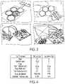
- FIG. 3illustrates exemplary fab devices.
- FIG. 4illustrates a table
- FIG. 5illustrates exemplary plots.
- FIG. 6illustrates exemplary simulation results.
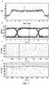
- FIG. 7illustrates exemplary graphs.
- FIG. 8illustrates exemplary fused silica packaging.
- the present inventionleverages near-field wireless communication techniques and a flexible system architecture to create a platform technology which can easily and simultaneously access multiple areas of the brain and enables neuroscientists and clinicians to mix and match different neural probes to suit their individual needs.
- Distributed, self-contained nodesfloat on the cortical surface and are equipped with electronics for full broadband neural data acquisition and stimulation for up to 128 channels, a programmable controller for on-board prototyping of processing algorithms, and wireless powering and communication.
- Each nodeis hermetically sealed for chronic implantation with individual package feedthroughs for each electrical channel.
- the packaged electronicsare independent of the type of electrodes which may be bonded to the electrical feedthroughs. In this way, as new neural probes are developed, probe designers need only to connect their interfaces to a node and can leverage the rest of the system to robustly communicate with their device thus resulting in significantly faster development times.
- An array of inductive coilsis placed epidurally and used to send wireless power and data to each of the implanted nodes. Without the need for transdural wiring, nodes can float with the brain's movements making a robust platform that does not suffer from the same limitations listed above for tethered micro-electrode arrays (MEAs).
- MEAsmicro-electrode arrays
- the antenna arrayis designed using overlapping coils making the system agnostic to surgical placement of the nodes and is robust to node movement. Therefore, the system can support multiple implanted nodes which are spatially isolated across distal brain regions. Without tethering, the nodes are easier to implant than traditional MEAS.
- the antenna arrayencapsulated in an elastomeric polymer, mechanically resembles ECoG grids which are routinely implanted in human patients.
- ECoG gridswhich are routinely implanted in human patients.
- On-board electronicsare re-programmable while the nodes are still implanted.
- New algorithmssuch as data compression or low power system control can be tested on-the fly, allowing for continuous device updates.
- New research paradigmsare also enabled as researchers gain the capability to run closed loop algorithms for either neural recording or stimulation at the interface itself. By eliminating significant latencies for communicating neural data using onboard computation, studies about fast time scale neural processes such as time-dependent plasticity or fast communication between cortical regions can be now be studied.
- FIG. 1illustrates an exemplary system architecture 100 .
- Spatially isolated nodes 120are implanted on the cortical surface and receive power and data from a telemetric antenna array 130 located above the dura.
- a power and data distribution unit 140powers the nodes while aggregating all the recorded data and sending them through a wireless optical link to an external controller 150 which is mounted to the patient's ear.
- the flexible electronic payload and modular architecture of the present inventionprovides a unique platform technology that enables new probe designs to be tested easily without additional development. Probe designers need only to bond their interface to a node 120 and can take advantage of all the system's features to test their design. While other floating “node-like” neural interfaces have been designed, many do not implement designs which facilitate multi-area distribution of the nodes 120 . Other devices have limited data telemetry bandwidth or focus on only electrical stimulation.
- the design 100specifically supports distributed nodes 120 each capable of transmitting high data rates and receiving enough wireless power from the antenna array 130 to support the capable electronics.
- a field programmable gate arrayprovides a unique opportunity for end-users to modify their use of the device.
- Each node 120can implement data analysis, data compression, closed loop stimulation, power saving control schemes, or other algorithms that expand the usefulness of the device and potentially uncover new techniques that could be used on future neural implants.
- Other devices which implement a FPGAdo not utilize it in such a flexible role.
- Such a designenables new research paradigms, expanding its market even to labs which may already employ other neural interfaces. It also allows for a deeper level of control over the implant for clinicians, and an ability for on-the-fly firmware updates.
- Each node 120 in the system 100uses glass packaging technology which is both RF and optically transparent and robust to ionic diffusion making a low profile hermetic seal which is suitable for long term implants.
- Each implanted node 120need not implement the same probes, are agnostic to surgical placement, and robust to small implant movements.
- the platform 100is ideal for mixing different probe types such as micro-electrode arrays, micro-ECoG grids, deep brain electrodes, and others to acquire a diverse set of signals from many parts of the brain.
- the system 100is useful across multiple domains and therefore is potentially viable in several different markets. It is useful as a research tool since it allows for easy implantation of several biological interface nodes which are spatially isolated. For example, interactions between distally located regions such as motor, visual, and pre-frontal cortices or between both cortical hemispheres can be studied using the same implant.
- the system 10is useful as a platform for engineers to test new probe technologies, or on-board processing algorithms. Finally, as the technology matures and the range of compatible probes grows, clinicians can use system 100 to implement large-scale, multimodal biological sensing and stimulation.
- itcan be used to facilitate existing technologies such as deep brain stimulation and epilepsy monitoring using ECoG, but also make more cutting-edge interfaces such as MEAs more accessible in the clinical domain, since the nodes are easier to implant than tethered MEAs and can move with the brain making them safer for human use.
- an exemplary block diagram 200illustrates the various modular components of the system 100 (of FIG. 1 ). It should be appreciated that other implementations may be employed in building the system 100 and that block diagram 200 is just one example implementation. All components of a node are wirelessly powered using a transdural inductive link enabling them to be positioned anywhere on the cortical surface.
- An ADC 210digitizes multiple channels of amplified neural signals, an FPGA 220 captures the data and packetizes them for wireless transmission.
- a 3.5 GHz OOK RF transmitter 230 ASICtelemeters the data wirelessly to an SDR computer-in-the-loop receiver 240 which demodulates and interprets the signal.
- a wireless power transfer subsystem 250includes inductive coils designed to transfer wireless power to neural interrogators.
- a feature of the platform 100is a desire to be agnostic to the placement of individual neural interrogator nodes on the cortical surface. To achieve this, a flexible array of coils resides above the dura and conforms to the cortical surface. Nodes, implanted subdurally, may then be placed anywhere underneath the antenna array, which maintains a coil density high enough to ensure that there will always be an inductor (coil) with minimal misalignment to each implanted node. By positioning the telemetric array 130 just above the dura, power transfer occurs over a very short distance and can therefore take advantage of high coupling coefficients between the coils.
- the primary and secondary coilsare essential for providing sufficient power to each node and must account for the electromagnetic interactions with the surrounding tissue.
- the diameter of the secondary coilis limited by the size of the node.
- Each primary coil in the telemetric array 130should be large enough to cover as much surface area of the brain as possible and to limit overall array complexity, yet small enough to maintain strong coupling with a given node.
- their shapemust allow multiple primary coils to be packed closely together in the array.
- the secondary coilis chosen to be a 1 ⁇ 1 cm, single turn, square coil, and the primary coil was chosen to be a 2-turn, hexagonal coil with a 10 mm apothem.
- FIG. 4illustrates Table 1, which details the dimensions of both coils.
- FIG. 3illustrates an example prototype of a node containing power rectification and regulation circuitry with an example resistive load of 603 .
- the nodecan be powered by a multi-coil telemetric array of hexagonal coils.
- (B)illustrates a prototype of the flexible telemetric array.
- the antenna arrayis surgically placed above the dura and conforms to the cortical surface.
- Cillustrates development boards for the ADS7042 ADC and iCE40UL1K FPGA used to validate the neural signal collection path. These chips are integrated into a node approximately 1 ⁇ 1 cm.
- Dillustrates an RF transmitter ASIC with an ultra-wide band antenna for sending neural data wirelessly, along with a receiver built using a receive antenna and a software defined radio.
- PTEPower transfer efficiency
- plots of power delivered to load (PDL) and power transfer efficiency (PTE) of the wireless power transmission from one coil of the telemetric array to an individual node for various (A) PA output powers, (B) coil separation distances, and (C) coil misalignment distancesare shown.
- Our systemtakes advantage of high coil coupling by ensuring that a node will always be both close to, and aligned with, at least one coil on the telemetric array.
- PTEP load /P PA
- P loadis the power delivered to the load and P PA is the power output of the PA as measured using a spectrum analyzer with 50 ⁇ input impedance. Since the input impedance of the telemetric array may be different than 50 ⁇ and will vary depending on coupling with the node, actual power delivered to the array during testing should be less than this estimation. Therefore, PTE calculations given here are a conservative estimate of the final system's capability. As can be seen in FIG. 5A , both PDL and PTE increase with increasing transmitter power, until the regulation voltage of the LDO is reached and no further power can be delivered to the load.
- This saturationoccurs at an output power of 25.12 mW (14 dBm) and also represents the point at which the target 15 mW is being delivered to the node (actual PDL was 14.3 mW), yielding a PTE of 56.9%.
- a separation distance of approximately 0.8 mmwas used in the above experiment using an ABS plastic spacer, the approximate thickness of the human dura mater.
- a PA output power of 23.44 mW (13.7 dBm)a value below the LDO threshold, was used to power a node positioned above the telemetric array using increasing layers of plastic spacers.
- FIG. 5Bshows that as distance increase, the PTE drops significantly.
- FIG. 5 Cdepicts a consistent PTE for misalignment less than 3 mm, but a steep drop in efficiency thereafter.
- Our resultsindicate that nodes can move up to 6 mm (3 mm radius) before deleterious loss of transmission efficiency is observed.
- a nearby coil with a more appropriate alignmentwill be able to perform this role.
- Leveraging techniquessuch as three-phase inductive powering can be used with adjacent coils to transfer power to a node which is not parallel to the surface of the telemetric array.
- Each nodemust be capable of capturing and digitizing full broadband neural data and passing it onto the wireless data telemetry subsystem. In order to fully capture typical single unit activity, a sample rate of approximately 15 kSps per channel is required. While future nodes will integrate all subsystems into a single ASIC, here we leveraged the Texas Instruments (Dallas, Tex.) ADS7042 analog to digital converter (ADC), which provides an off-the-shelf solution capable of a 1 MSPS sample rate with 12 bit resolution, and uses a SPI interface for simple communication. Additionally, the ADS7042 is available in a package that meets both the size and power constraints required by our design (1.5 ⁇ 1.5 mm; 690 ⁇ W).
- ADCanalog to digital converter
- each nodeBy multiplexing each channel onto the ADC input, each node is capable of acquiring up to 50 channels of neural data sampled at 20 kSps.
- FIG. 6 Aillustrates simulation results for the circuit implemented on the FPGA.
- 16 samplesare captured from the ADC and loaded into a FIFO buffer, a synchronization header is then appended to the packet and sent to the RF transmitter.
- One full transmission packetis indicated here.
- the cursormarks the falling edge of the CS signal, capturing a new sample.
- An 11 bit Barker codeis used to synchronize frames in the receiver. From the top down, the ADC chip select signal, serial clock, and serial data signals followed by the data output to be sent to the RF transmit ASIC are shown.
- Central control logicis required for multiplexing channels, interfacing with the ADC and telemetry unit, and preparing data for wireless transmission.
- FPGAscan be programmed to handle each of these tasks and are flexible enough to adapt if peripheral components change. Additionally, FPGAs allow design iterations to be implemented quickly in order to test new encoding or modulation schemes for wireless transmission, or even for on-node processing of acquired data to relieve the processing burden on downstream systems. Given these benefits, each node contains its own iCE40UL1K FPGA (Lattice Semiconductor, Portland, Oreg.), or equivalent fabric in the future.
- FIG. 6Adepicts this process.
- the system clockis generated using the chip's clk integrated 48 MHz oscillator (i_clk).
- o_cs_nOn the first falling edge of the chip select signal (o_cs_n), the ADS7042 undergoes a self calibration process. Each subsequent falling edge of o_cs_n triggers the ADC to capture a sample.
- the sampled and digitized datais then clocked out by the falling edges of the serial clock pin (o_sclk) which trigger the ADC to generate each bit of the serial data out signal (i_sclk) containing the digitized data.
- the datais written to a first-in-first-out (FIFO) buffer implemented using on-chip block RAM (BRAM).
- An internal write enable signal (w_wr_en)indicates when each new sample is written to the FIFO. As FIG. 6A shows 16 samples written to the FIFO before any output is sent to the wireless data transmitter (o_pin).
- the FIFOwaits for all 16 samples of the first wireless packet to be captured before clearing an “almost empty” signal (w_ae) which triggers a separate logic module to transmit a synchronization header followed by the serialized data from each of these 16 samples.
- w_aean “almost empty” signal
- the ADC capture circuitryis isolated from the data transmission circuitry and the protocol or rate of one can change without affecting the other as long as all the data in one packet is written to the transmit chip in the same amount of time it takes to read the next 16 samples from the ADC.
- the FPGAadds two copies of an 11 bit Barker code (11100010010) as the synchronization header, followed by the 16 packet samples.
- FIG. 6Bshows each of these external signals operating as expected in the design.
- the top tracerepresents o_cs_n triggering each ADC sample.
- the middle traceis the o_sclk signal clocking out each bit from the ADC which sends the data in the third trace (i_sdo).
- the bottom traceis the signal sent to the wireless transmitter and shows the end of the previous packet, followed by a short pause, and the beginning of the next packet containing the synchronization header.
- the dataare sent to a printed circuit board containing an ASIC for wireless transmission ( FIG. 3D ).
- Datais modulated onto a carrier signal of approximately 3.5 GHz (tunable between 3 and 4 GHz) using on-off shift keying (OOK).
- OOKon-off shift keying
- This frequency rangewas specifically chosen to reside outside of other commonly used bands found in a clinical setting therefore reducing potential interference. In addition, it is much higher than the 48.4 MHz signal used for powering the nodes and therefore should not be affected by the wireless powering mechanism.
- An integrated PAdrives an ultra-wide band (3.1-5 GHz) antenna (Fractus Antennas, Barcelona, Spain) through an impedance matching network.
- Initial prototypes of the neural interrogatorssupport 16 channels of full-spectrum neural data, requiring a baseband data rate of approximately 4.3 Mbps.
- the transmitter ASICcan send up to 200 Mbps and has been successfully used for transmitting up to 100 channels of neural data 1-2 meters away, using only one quarter of this data rate.
- each nodewill contain its own transmit chip tuned to a separate frequency channel all communicating with a central wireless receiver.
- Additional multiplexing techniquesfor example code division multiplexing (CDMA), multiple input multiple output (MIMO) techniques, and spatial multiplexing may be evaluated to improve the scalability of the system.
- the wirelessly transmitted datamust be received and demodulated in order to recover the original signal.
- a software defined radioutilizing the AD9361 2 ⁇ 2 transceiver (Analog Devices, Norwood, Mass.) and the Zynq Z-7035 system-on-chip (Xilinx, San Jose, Calif.) was used to build a computer-in-the-loop algorithm in SimulinkTM (The MathWorks, Natick, Mass.) for down-mixing the wireless signal, demodulating the OOK data, and sampling each bit.
- the algorithmsearches for the synchronization header and breaks the packet into its constituent samples.
- the RF front end of the SDRis contained within the AD9361, which first mixes the carrier-modulated data stream down to near-baseband.
- FIG. 7Ashows a spectrum plot generated from the sampled baseband signal captured by the SDR when tuned to 3.5 GHz without any data modulation on the transmitter carrier frequency. From this plot, a small mismatch is observed between the oscillators on the transmit chip and the SDR. Once tuned near the carrier frequency, the SDR generates I and Q samples of the down-converted signal and sends them to a computer, which calculates the magnitude of these complex samples yielding a clean baseband representation of the original modulated data. Fine tuning the baseband sample rate allows for an eye diagram to be generated to evaluate the robustness of the individual symbols received by the SDR ( FIG. 7B ). Each symbol is represented by approximately 12 baseband samples.
- Bit slicingoccurs on the host computer which then searches for the header of each packet and converts the samples to 12 bit numbers.
- the SDRsends frames composed of 640,000 samples of I and Q baseband data. Future work will eliminate the need for the host computer by recovering data directly on the SDR receiver, thereby preventing data loss between frames.
- Plots C and D of FIG. 7show the resultant demodulated and decoded signals from one of these frames.
- FIG. 7Ca 1 kHz sine wave was played into the ADC using a bench top signal generator. The signal then propagates through each component of the system described above and is successfully reconstructed by the receiver. Similarly, in FIG.
- FIG. 7(A)illustrates a spectrum of the transmitter carrier signal captured from the SDR.
- the peak valuewas measured at ⁇ 6.48 dBm, after RF front end amplification, at 3.82 MHz, indicating a small frequency offset between the oscillators on the transmitter and SDR when both are tuned to 3.5 GHz.
- (B)illustrates an eye diagram depicting the baseband signal using a sample rate of 52.40985 MHz yielding approximately 12 bits per symbol. Reconstructed samples of both a (C) 1 kHz sine wave and (D) prerecorded neural action potential data from a nonhuman primate walking on a treadmill are illustrated. In these examples, all 16 channels of the packet are being used to encode these data, yielding a sample rate of 320 kSPS. Ultimately this sample rate can be divided to support multiple channels of neural signal acquisition.
- Titanium and ceramicsare among the most widely used rigid packaging materials for chronic device implants in the human body. Titanium and ceramics have, for example, been successfully used in pacemakers, cardiac defibrillators, deep brain stimulators, and cochlear implants (among others) for hermetically sealing active electronic components away from the biological system in which they are implanted; many more materials may be on the horizon. Recently, thin film coatings that combine metals, polymers, and ceramics to seal electronics have been brought from the microelectronics industry and provide micro-thick seals where space is paramount. We propose the use of a highly manufacturable packaging platform that enables simple and direct integration of both existing and future MEAs with hermetically-sealed active electronics.
- FIG. 8illustrates exemplary fused silica packaging.
- Ashows the step-by-step fabrication and bonding process of the test device
- the Kapton substrateis pre-patterned with metal traces and contacts using standard micro-fabrication process and was bonded onto a pre-made, thin fused silica sheet (130 um) with adhesives.
- the substrateis then populated with solder-mounted commercial off-the-shelf (COTS) test components and wire-bonded Application Specific Integration Circuit (ASIC).
- COTScommercial off-the-shelf
- ASICApplication Specific Integration Circuit
- the fully-populated substrateis mounted onto a fused silica interposer with adhesives.
- a pre-made, fused silica cavityis aligned with the substrate.
- a bonding treatmentis applied following the perimeter of the cavity so that the cavity bonds onto the interposer forming a water and ion tight seal.
- the thickness of the fused silica interposer and cavityare indicated in the figure.
- the final packaged devicefeatures a total thickness of 2.1 mm.
- (B)shows one corner of the cavity after immersion test in liquid. The 7 dark lines are the bond lines used in the bonding process. Light colored area is the reflection from the material interface while dark colored area is the liquid in the interface, which does not penetrate the bond.
- Cillustrates an overview picture of the cavities after bonding and dicing.
Landscapes
- Health & Medical Sciences (AREA)
- Life Sciences & Earth Sciences (AREA)
- Engineering & Computer Science (AREA)
- Veterinary Medicine (AREA)
- Animal Behavior & Ethology (AREA)
- Biomedical Technology (AREA)
- Public Health (AREA)
- General Health & Medical Sciences (AREA)
- Radiology & Medical Imaging (AREA)
- Neurology (AREA)
- Nuclear Medicine, Radiotherapy & Molecular Imaging (AREA)
- Neurosurgery (AREA)
- Heart & Thoracic Surgery (AREA)
- Psychology (AREA)
- Cardiology (AREA)
- Biophysics (AREA)
- Hospice & Palliative Care (AREA)
- Medical Informatics (AREA)
- Pathology (AREA)
- Molecular Biology (AREA)
- Physics & Mathematics (AREA)
- Child & Adolescent Psychology (AREA)
- Developmental Disabilities (AREA)
- Surgery (AREA)
- Psychiatry (AREA)
- Orthopedic Medicine & Surgery (AREA)
- Social Psychology (AREA)
- Physiology (AREA)
- Electrotherapy Devices (AREA)
Abstract
Description
PTE=Pload/PPA
Claims (12)
Priority Applications (1)
| Application Number | Priority Date | Filing Date | Title |
|---|---|---|---|
| US16/530,619US11464964B2 (en) | 2018-08-03 | 2019-08-02 | Neural interrogation platform |
Applications Claiming Priority (2)
| Application Number | Priority Date | Filing Date | Title |
|---|---|---|---|
| US201862714565P | 2018-08-03 | 2018-08-03 | |
| US16/530,619US11464964B2 (en) | 2018-08-03 | 2019-08-02 | Neural interrogation platform |
Publications (2)
| Publication Number | Publication Date |
|---|---|
| US20200038651A1 US20200038651A1 (en) | 2020-02-06 |
| US11464964B2true US11464964B2 (en) | 2022-10-11 |
Family
ID=69228168
Family Applications (1)
| Application Number | Title | Priority Date | Filing Date |
|---|---|---|---|
| US16/530,619ActiveUS11464964B2 (en) | 2018-08-03 | 2019-08-02 | Neural interrogation platform |
Country Status (1)
| Country | Link |
|---|---|
| US (1) | US11464964B2 (en) |
Families Citing this family (1)
| Publication number | Priority date | Publication date | Assignee | Title |
|---|---|---|---|---|
| US12294380B2 (en) | 2022-05-16 | 2025-05-06 | Analog Devices International Unlimited Company | Power saving encoding for isolated galvanically data transmission |
Citations (81)
| Publication number | Priority date | Publication date | Assignee | Title |
|---|---|---|---|---|
| US3867950A (en)* | 1971-06-18 | 1975-02-25 | Univ Johns Hopkins | Fixed rate rechargeable cardiac pacemaker |
| US20030176905A1 (en)* | 2002-03-14 | 2003-09-18 | Nicolelis Miguel A.L. | Miniaturized high-density multichannel electrode array for long-term neuronal recordings |
| US20050143790A1 (en)* | 2003-10-21 | 2005-06-30 | Kipke Daryl R. | Intracranial neural interface system |
| US20050187594A1 (en)* | 2004-02-20 | 2005-08-25 | Hatlestad John D. | System and method for transmitting energy to and establishing a communications network with one or more implanted devices |
| US20060142803A1 (en)* | 2003-11-28 | 2006-06-29 | University Technologies International Inc. | Gastrointestinal motility control |
| US20060173259A1 (en)* | 2004-10-04 | 2006-08-03 | Flaherty J C | Biological interface system |
| US7346312B2 (en)* | 2004-10-23 | 2008-03-18 | Triangle Biosystems, Inc. | Wireless neural data acquisition system |
| US20090182426A1 (en)* | 2008-01-15 | 2009-07-16 | Jeffrey Allen Von Arx | Implantable medical device with antenna |
| US20100100010A1 (en)* | 2008-10-21 | 2010-04-22 | General Electric Company | Implantable device system |
| US20100190229A1 (en)* | 2005-07-22 | 2010-07-29 | Feng Zhang | System for optical stimulation of target cells |
| US20110054583A1 (en)* | 2008-03-12 | 2011-03-03 | Brian Litt | Flexible and Scalable Sensor Arrays for Recording and Modulating Physiologic Activity |
| US7991475B1 (en)* | 2005-06-08 | 2011-08-02 | The Regents Of The University Of California | High density micromachined electrode arrays useable for auditory nerve implants and related methods |
| US20110230747A1 (en)* | 2010-03-17 | 2011-09-22 | Rogers John A | Implantable biomedical devices on bioresorbable substrates |
| US20110307079A1 (en)* | 2010-04-29 | 2011-12-15 | Board Of Trustees Of Michigan State University, The | Multiscale intra-cortical neural interface system |
| US8121694B2 (en)* | 2007-10-16 | 2012-02-21 | Medtronic, Inc. | Therapy control based on a patient movement state |
| US20120165759A1 (en)* | 2009-12-16 | 2012-06-28 | Rogers John A | Waterproof stretchable optoelectronics |
| US20120238855A1 (en)* | 2007-08-01 | 2012-09-20 | Bruce Lanning | Wireless system for epilepsy monitoring and measurement |
| US20120283800A1 (en)* | 2011-01-28 | 2012-11-08 | Stimwave Technologies Incorporated | Neural Stimulator System |
| US20120296444A1 (en)* | 2011-05-16 | 2012-11-22 | Greenberg Robert J | Cortical Interface for Motor Signal Recording and Sensory Signal Stimulation |
| US8332024B2 (en)* | 2007-05-25 | 2012-12-11 | Massachusetts Institute Of Technology | Low-power analog architecture for brain-machine interfaces |
| US20130041235A1 (en)* | 2009-12-16 | 2013-02-14 | John A. Rogers | Flexible and Stretchable Electronic Systems for Epidermal Electronics |
| US8380314B2 (en)* | 2007-09-26 | 2013-02-19 | Medtronic, Inc. | Patient directed therapy control |
| US20130066400A1 (en)* | 2011-01-28 | 2013-03-14 | Stimwave Technologies Incorporated | Microwave field stimulator |
| US20130072775A1 (en)* | 2011-06-03 | 2013-03-21 | John Rogers | Conformable Actively Multiplexed High-Density Surface Electrode Array for Brain Interfacing |
| US8423143B2 (en)* | 2005-05-20 | 2013-04-16 | Imec | Probe device for electrical stimulation and recording of the activity of excitable cells |
| US8457757B2 (en)* | 2007-11-26 | 2013-06-04 | Micro Transponder, Inc. | Implantable transponder systems and methods |
| US20140031607A1 (en)* | 2011-08-19 | 2014-01-30 | Leviticus Cardio Ltd. | Coplanar Wireless Energy Transfer |
| US20140094674A1 (en)* | 2011-03-17 | 2014-04-03 | Brown University | Implantable wireless neural device |
| US20140257052A1 (en)* | 2013-03-11 | 2014-09-11 | The Regents Of The University Of California | Monolithically integrated implantable flexible antenna for electrocorticography and related biotelemetry devices |
| US20140288393A1 (en)* | 2007-04-30 | 2014-09-25 | Medtronic, Inc. | Chopper mixer telemetry circuit |
| US20150039054A1 (en)* | 2006-08-10 | 2015-02-05 | Jeffrey A. Matos | Implantable medical device which may be controlled from central station |
| US20150112233A1 (en)* | 2012-05-22 | 2015-04-23 | Arizona Board Of Regents On Behalf Of Arizona State University | Apparatus, System and Method for Neurostimulation by High Frequency Ultrasound |
| US20150148878A1 (en)* | 2013-11-27 | 2015-05-28 | The Governing Council Of The University Of Toronto | Systems and methods of enhancing electrical activation of nervous tissue |
| US20150153319A1 (en)* | 2013-12-04 | 2015-06-04 | California Institute Of Technology | Sensing and actuation of biological function using addressable transmitters operated as magnetic spins |
| US20150157862A1 (en)* | 2013-12-06 | 2015-06-11 | Second Sight Medical Products, Inc. | Cortical Implant System for Brain Stimulation and Recording |
| US20150217120A1 (en)* | 2014-01-13 | 2015-08-06 | Mandheerej Nandra | Neuromodulation systems and methods of using same |
| US20150223971A1 (en)* | 2012-09-07 | 2015-08-13 | Yale University | Brain cooling system |
| US20150297900A1 (en)* | 2012-12-05 | 2015-10-22 | Micron Devices Llc | Devices and methods for connecting implantable devices to wireless energy |
| US20150351654A1 (en)* | 2013-02-27 | 2015-12-10 | Widex A/S | Electrode and leakage current testing in an eeg monitor with an implantable part |
| US9211401B2 (en)* | 2009-11-30 | 2015-12-15 | University Of South Florida | Cubic silicon carbide implantable neural prosthetic |
| US20150373831A1 (en)* | 2013-02-06 | 2015-12-24 | Lin Jia | Stretchable electronic systems with containment chambers |
| US20150380355A1 (en)* | 2013-02-06 | 2015-12-31 | John A. Rogers | Self-similar and fractal design for stretchable electronics |
| US20160110643A1 (en)* | 2014-10-16 | 2016-04-21 | Nanyang Technological University | Systems and methods for classifying electrical signals |
| US9387320B2 (en)* | 2007-10-30 | 2016-07-12 | Neuropace, Inc. | Systems, methods and devices for a skull/brain interface |
| US20160278713A1 (en)* | 2015-03-25 | 2016-09-29 | Ecole Polytechnique Federale De Lausanne (Epfl) | Compact low-power recording architecture for multichannel acquisition of biological signals and method for compressing said biological signal data |
| US20160339239A1 (en)* | 2015-05-21 | 2016-11-24 | The Governing Council Of The University Of Toronto | Systems and methods for treatment of urinary dysfunction |
| US20170042474A1 (en)* | 2014-04-25 | 2017-02-16 | The General Hospital Corporation | Method for cross-diagnostic identification and treatment of neurologic features underpinning mental and emotional disorders |
| US20170095667A1 (en)* | 2014-03-14 | 2017-04-06 | Nalu Medical, Inc. | Method and apparatus for neuromodulation treatments of pain and other conditions |
| US20170108926A1 (en)* | 2015-10-20 | 2017-04-20 | The San Diego University Research Foundation | Apparatus and method of implantable bidirectional wireless neural recording and stimulation |
| US20170113046A1 (en)* | 2014-06-09 | 2017-04-27 | The Regents Of The University Of California | Systems and methods for restoring cognitive function |
| US9662498B1 (en)* | 2014-03-27 | 2017-05-30 | Hrl Laboratories, Llc | Scalable high-density wireless neuroelectric sensor and stimulator array |
| US20170173345A1 (en)* | 2015-12-18 | 2017-06-22 | The Regents Of The University Of California | Multi-Tiered Wireless Powering System for Long-Term Implantable Medical Devices |
| US9691873B2 (en)* | 2011-12-01 | 2017-06-27 | The Board Of Trustees Of The University Of Illinois | Transient devices designed to undergo programmable transformations |
| US20170189699A1 (en)* | 2016-01-06 | 2017-07-06 | Syntilla Medical LLC | Charging system incorporating independent charging and communication with multiple implanted devices |
| US20170368330A1 (en)* | 2016-06-27 | 2017-12-28 | Ecole Polytechnique Federale De Lausanne (Epfl) | System for Active Skull Replacement for Brain Interface and Method of Using the Same |
| US20180085605A1 (en)* | 2016-07-07 | 2018-03-29 | The Regents Of The University Of California | Implants using ultrasonic backscatter for sensing physiological conditions |
| US20180165566A1 (en)* | 2015-06-01 | 2018-06-14 | The Board Of Trustees Of The University Of Illinois | Miniaturized electronic systems with wireless power and near-field communication capabilities |
| US20180185657A1 (en)* | 2016-01-15 | 2018-07-05 | Micron Devices Llc | Implantable relay module |
| US20180236230A1 (en)* | 2014-06-23 | 2018-08-23 | Hrl Laboratories, Llc | Method and apparatus to determine optimal brain stimulation to induce desired behavior |
| US20180333587A1 (en)* | 2016-04-22 | 2018-11-22 | Newton Howard | Brain-machine interface (bmi) |
| US20180356771A1 (en)* | 2015-09-17 | 2018-12-13 | Nanyang Technologyical University | Computer system incorporating an adaptive model and methods for training the adaptive model |
| US20190038899A1 (en)* | 2016-01-27 | 2019-02-07 | The Regents Of The University Of California | Wireless implant for motor function recovery after spinal cord injury |
| US20190053712A1 (en)* | 2016-04-01 | 2019-02-21 | The Board Of Trustees Of The University Of Illinois | Implantable medical devices for optogenetics |
| US10265530B1 (en)* | 2014-05-29 | 2019-04-23 | Stimwave Technologies Incorporated | Simulation with electrode arrays |
| US20190126047A1 (en)* | 2016-07-20 | 2019-05-02 | The Governing Council Of The University Of Toronto | Neurostimulator and method for delivering a stimulation in response to a predicted or detected neurophysiological condition |
| US10386360B2 (en)* | 2009-03-13 | 2019-08-20 | University Of Central Florida Research Foundation, Inc. | Bio-microelectromechanical system transducer and associated methods |
| US20190275328A1 (en)* | 2016-01-20 | 2019-09-12 | Setpoint Medical Corporation | Batteryless implantable microstimulators |
| US10432025B2 (en)* | 2013-06-28 | 2019-10-01 | Polyvalor, Limited Partnership | Smart multicoil inductively-coupled array for wireless power transmission |
| US10497633B2 (en)* | 2013-02-06 | 2019-12-03 | The Board Of Trustees Of The University Of Illinois | Stretchable electronic systems with fluid containment |
| US20190374777A1 (en)* | 2017-01-05 | 2019-12-12 | California Institute Of Technology | Dueling bandits algorithm for neuromodulation therapy |
| US20200060607A1 (en)* | 2017-03-07 | 2020-02-27 | University Of Southampton | Intra-uterine monitoring system |
| US10603493B2 (en)* | 2012-08-02 | 2020-03-31 | The Regents Of The University Of California | Integrated nanowire array devices for detecting and/or applying electrical signals to tissue |
| US20200222010A1 (en)* | 2016-04-22 | 2020-07-16 | Newton Howard | System and method for deep mind analysis |
| US20200298005A1 (en)* | 2017-05-26 | 2020-09-24 | Newton Howard | Brain-machine interface (bmi) |
| US20200315477A1 (en)* | 2016-05-20 | 2020-10-08 | Imperial Innovations Limited | Implantable Neural Interface |
| US20200405204A1 (en)* | 2016-04-22 | 2020-12-31 | Newton Howard | Detection of catecholamine levels inside the neurocranium |
| US10938397B2 (en)* | 2016-11-03 | 2021-03-02 | University Of Washington | Recording channels for biopotential signals |
| US20210059526A1 (en)* | 2018-01-18 | 2021-03-04 | Oslo Universitetssykehus Hf | Medical implant with wireless communication |
| US20210138249A1 (en)* | 2016-04-22 | 2021-05-13 | Newton Howard | System and method for neural stimulation using spike frequency modulation |
| US20210162223A1 (en)* | 2018-04-13 | 2021-06-03 | The Penn State Research Foundation | Free-floating millimeter-sized distributed implantable gastric seeds |
| US20210194289A1 (en)* | 2019-12-18 | 2021-06-24 | Medtronic, Inc. | Implantable medical system with external power charger |
- 2019
- 2019-08-02USUS16/530,619patent/US11464964B2/enactiveActive
Patent Citations (82)
| Publication number | Priority date | Publication date | Assignee | Title |
|---|---|---|---|---|
| US3867950A (en)* | 1971-06-18 | 1975-02-25 | Univ Johns Hopkins | Fixed rate rechargeable cardiac pacemaker |
| US20030176905A1 (en)* | 2002-03-14 | 2003-09-18 | Nicolelis Miguel A.L. | Miniaturized high-density multichannel electrode array for long-term neuronal recordings |
| US20050143790A1 (en)* | 2003-10-21 | 2005-06-30 | Kipke Daryl R. | Intracranial neural interface system |
| US20060142803A1 (en)* | 2003-11-28 | 2006-06-29 | University Technologies International Inc. | Gastrointestinal motility control |
| US20050187594A1 (en)* | 2004-02-20 | 2005-08-25 | Hatlestad John D. | System and method for transmitting energy to and establishing a communications network with one or more implanted devices |
| US20060173259A1 (en)* | 2004-10-04 | 2006-08-03 | Flaherty J C | Biological interface system |
| US7346312B2 (en)* | 2004-10-23 | 2008-03-18 | Triangle Biosystems, Inc. | Wireless neural data acquisition system |
| US8423143B2 (en)* | 2005-05-20 | 2013-04-16 | Imec | Probe device for electrical stimulation and recording of the activity of excitable cells |
| US7991475B1 (en)* | 2005-06-08 | 2011-08-02 | The Regents Of The University Of California | High density micromachined electrode arrays useable for auditory nerve implants and related methods |
| US20100190229A1 (en)* | 2005-07-22 | 2010-07-29 | Feng Zhang | System for optical stimulation of target cells |
| US20150039054A1 (en)* | 2006-08-10 | 2015-02-05 | Jeffrey A. Matos | Implantable medical device which may be controlled from central station |
| US20140288393A1 (en)* | 2007-04-30 | 2014-09-25 | Medtronic, Inc. | Chopper mixer telemetry circuit |
| US8332024B2 (en)* | 2007-05-25 | 2012-12-11 | Massachusetts Institute Of Technology | Low-power analog architecture for brain-machine interfaces |
| US20120238855A1 (en)* | 2007-08-01 | 2012-09-20 | Bruce Lanning | Wireless system for epilepsy monitoring and measurement |
| US8380314B2 (en)* | 2007-09-26 | 2013-02-19 | Medtronic, Inc. | Patient directed therapy control |
| US8121694B2 (en)* | 2007-10-16 | 2012-02-21 | Medtronic, Inc. | Therapy control based on a patient movement state |
| US9387320B2 (en)* | 2007-10-30 | 2016-07-12 | Neuropace, Inc. | Systems, methods and devices for a skull/brain interface |
| US8457757B2 (en)* | 2007-11-26 | 2013-06-04 | Micro Transponder, Inc. | Implantable transponder systems and methods |
| US20090182426A1 (en)* | 2008-01-15 | 2009-07-16 | Jeffrey Allen Von Arx | Implantable medical device with antenna |
| US20110054583A1 (en)* | 2008-03-12 | 2011-03-03 | Brian Litt | Flexible and Scalable Sensor Arrays for Recording and Modulating Physiologic Activity |
| US20100100010A1 (en)* | 2008-10-21 | 2010-04-22 | General Electric Company | Implantable device system |
| US10386360B2 (en)* | 2009-03-13 | 2019-08-20 | University Of Central Florida Research Foundation, Inc. | Bio-microelectromechanical system transducer and associated methods |
| US9211401B2 (en)* | 2009-11-30 | 2015-12-15 | University Of South Florida | Cubic silicon carbide implantable neural prosthetic |
| US10441185B2 (en)* | 2009-12-16 | 2019-10-15 | The Board Of Trustees Of The University Of Illinois | Flexible and stretchable electronic systems for epidermal electronics |
| US20120165759A1 (en)* | 2009-12-16 | 2012-06-28 | Rogers John A | Waterproof stretchable optoelectronics |
| US20130041235A1 (en)* | 2009-12-16 | 2013-02-14 | John A. Rogers | Flexible and Stretchable Electronic Systems for Epidermal Electronics |
| US20110230747A1 (en)* | 2010-03-17 | 2011-09-22 | Rogers John A | Implantable biomedical devices on bioresorbable substrates |
| US20110307079A1 (en)* | 2010-04-29 | 2011-12-15 | Board Of Trustees Of Michigan State University, The | Multiscale intra-cortical neural interface system |
| US20130066400A1 (en)* | 2011-01-28 | 2013-03-14 | Stimwave Technologies Incorporated | Microwave field stimulator |
| US20120283800A1 (en)* | 2011-01-28 | 2012-11-08 | Stimwave Technologies Incorporated | Neural Stimulator System |
| US20140094674A1 (en)* | 2011-03-17 | 2014-04-03 | Brown University | Implantable wireless neural device |
| US20120296444A1 (en)* | 2011-05-16 | 2012-11-22 | Greenberg Robert J | Cortical Interface for Motor Signal Recording and Sensory Signal Stimulation |
| US20130072775A1 (en)* | 2011-06-03 | 2013-03-21 | John Rogers | Conformable Actively Multiplexed High-Density Surface Electrode Array for Brain Interfacing |
| US20140031607A1 (en)* | 2011-08-19 | 2014-01-30 | Leviticus Cardio Ltd. | Coplanar Wireless Energy Transfer |
| US9691873B2 (en)* | 2011-12-01 | 2017-06-27 | The Board Of Trustees Of The University Of Illinois | Transient devices designed to undergo programmable transformations |
| US20150112233A1 (en)* | 2012-05-22 | 2015-04-23 | Arizona Board Of Regents On Behalf Of Arizona State University | Apparatus, System and Method for Neurostimulation by High Frequency Ultrasound |
| US10603493B2 (en)* | 2012-08-02 | 2020-03-31 | The Regents Of The University Of California | Integrated nanowire array devices for detecting and/or applying electrical signals to tissue |
| US20150223971A1 (en)* | 2012-09-07 | 2015-08-13 | Yale University | Brain cooling system |
| US20150297900A1 (en)* | 2012-12-05 | 2015-10-22 | Micron Devices Llc | Devices and methods for connecting implantable devices to wireless energy |
| US20150373831A1 (en)* | 2013-02-06 | 2015-12-24 | Lin Jia | Stretchable electronic systems with containment chambers |
| US20150380355A1 (en)* | 2013-02-06 | 2015-12-31 | John A. Rogers | Self-similar and fractal design for stretchable electronics |
| US10497633B2 (en)* | 2013-02-06 | 2019-12-03 | The Board Of Trustees Of The University Of Illinois | Stretchable electronic systems with fluid containment |
| US20150351654A1 (en)* | 2013-02-27 | 2015-12-10 | Widex A/S | Electrode and leakage current testing in an eeg monitor with an implantable part |
| US20140257052A1 (en)* | 2013-03-11 | 2014-09-11 | The Regents Of The University Of California | Monolithically integrated implantable flexible antenna for electrocorticography and related biotelemetry devices |
| US10432025B2 (en)* | 2013-06-28 | 2019-10-01 | Polyvalor, Limited Partnership | Smart multicoil inductively-coupled array for wireless power transmission |
| US20150148878A1 (en)* | 2013-11-27 | 2015-05-28 | The Governing Council Of The University Of Toronto | Systems and methods of enhancing electrical activation of nervous tissue |
| US20150153319A1 (en)* | 2013-12-04 | 2015-06-04 | California Institute Of Technology | Sensing and actuation of biological function using addressable transmitters operated as magnetic spins |
| US20150157862A1 (en)* | 2013-12-06 | 2015-06-11 | Second Sight Medical Products, Inc. | Cortical Implant System for Brain Stimulation and Recording |
| US20150217120A1 (en)* | 2014-01-13 | 2015-08-06 | Mandheerej Nandra | Neuromodulation systems and methods of using same |
| US20170095667A1 (en)* | 2014-03-14 | 2017-04-06 | Nalu Medical, Inc. | Method and apparatus for neuromodulation treatments of pain and other conditions |
| US9662498B1 (en)* | 2014-03-27 | 2017-05-30 | Hrl Laboratories, Llc | Scalable high-density wireless neuroelectric sensor and stimulator array |
| US20170042474A1 (en)* | 2014-04-25 | 2017-02-16 | The General Hospital Corporation | Method for cross-diagnostic identification and treatment of neurologic features underpinning mental and emotional disorders |
| US10265530B1 (en)* | 2014-05-29 | 2019-04-23 | Stimwave Technologies Incorporated | Simulation with electrode arrays |
| US20170113046A1 (en)* | 2014-06-09 | 2017-04-27 | The Regents Of The University Of California | Systems and methods for restoring cognitive function |
| US20180236230A1 (en)* | 2014-06-23 | 2018-08-23 | Hrl Laboratories, Llc | Method and apparatus to determine optimal brain stimulation to induce desired behavior |
| US20160110643A1 (en)* | 2014-10-16 | 2016-04-21 | Nanyang Technological University | Systems and methods for classifying electrical signals |
| US20160278713A1 (en)* | 2015-03-25 | 2016-09-29 | Ecole Polytechnique Federale De Lausanne (Epfl) | Compact low-power recording architecture for multichannel acquisition of biological signals and method for compressing said biological signal data |
| US20160339239A1 (en)* | 2015-05-21 | 2016-11-24 | The Governing Council Of The University Of Toronto | Systems and methods for treatment of urinary dysfunction |
| US20180165566A1 (en)* | 2015-06-01 | 2018-06-14 | The Board Of Trustees Of The University Of Illinois | Miniaturized electronic systems with wireless power and near-field communication capabilities |
| US20180356771A1 (en)* | 2015-09-17 | 2018-12-13 | Nanyang Technologyical University | Computer system incorporating an adaptive model and methods for training the adaptive model |
| US20170108926A1 (en)* | 2015-10-20 | 2017-04-20 | The San Diego University Research Foundation | Apparatus and method of implantable bidirectional wireless neural recording and stimulation |
| US20170173345A1 (en)* | 2015-12-18 | 2017-06-22 | The Regents Of The University Of California | Multi-Tiered Wireless Powering System for Long-Term Implantable Medical Devices |
| US20170189699A1 (en)* | 2016-01-06 | 2017-07-06 | Syntilla Medical LLC | Charging system incorporating independent charging and communication with multiple implanted devices |
| US20180185657A1 (en)* | 2016-01-15 | 2018-07-05 | Micron Devices Llc | Implantable relay module |
| US20190275328A1 (en)* | 2016-01-20 | 2019-09-12 | Setpoint Medical Corporation | Batteryless implantable microstimulators |
| US20190038899A1 (en)* | 2016-01-27 | 2019-02-07 | The Regents Of The University Of California | Wireless implant for motor function recovery after spinal cord injury |
| US20190053712A1 (en)* | 2016-04-01 | 2019-02-21 | The Board Of Trustees Of The University Of Illinois | Implantable medical devices for optogenetics |
| US20210138249A1 (en)* | 2016-04-22 | 2021-05-13 | Newton Howard | System and method for neural stimulation using spike frequency modulation |
| US20180333587A1 (en)* | 2016-04-22 | 2018-11-22 | Newton Howard | Brain-machine interface (bmi) |
| US20200222010A1 (en)* | 2016-04-22 | 2020-07-16 | Newton Howard | System and method for deep mind analysis |
| US20200405204A1 (en)* | 2016-04-22 | 2020-12-31 | Newton Howard | Detection of catecholamine levels inside the neurocranium |
| US20200315477A1 (en)* | 2016-05-20 | 2020-10-08 | Imperial Innovations Limited | Implantable Neural Interface |
| US20170368330A1 (en)* | 2016-06-27 | 2017-12-28 | Ecole Polytechnique Federale De Lausanne (Epfl) | System for Active Skull Replacement for Brain Interface and Method of Using the Same |
| US20180085605A1 (en)* | 2016-07-07 | 2018-03-29 | The Regents Of The University Of California | Implants using ultrasonic backscatter for sensing physiological conditions |
| US20190126047A1 (en)* | 2016-07-20 | 2019-05-02 | The Governing Council Of The University Of Toronto | Neurostimulator and method for delivering a stimulation in response to a predicted or detected neurophysiological condition |
| US10938397B2 (en)* | 2016-11-03 | 2021-03-02 | University Of Washington | Recording channels for biopotential signals |
| US20190374777A1 (en)* | 2017-01-05 | 2019-12-12 | California Institute Of Technology | Dueling bandits algorithm for neuromodulation therapy |
| US20200060607A1 (en)* | 2017-03-07 | 2020-02-27 | University Of Southampton | Intra-uterine monitoring system |
| US20200298005A1 (en)* | 2017-05-26 | 2020-09-24 | Newton Howard | Brain-machine interface (bmi) |
| US20210059526A1 (en)* | 2018-01-18 | 2021-03-04 | Oslo Universitetssykehus Hf | Medical implant with wireless communication |
| US20210162223A1 (en)* | 2018-04-13 | 2021-06-03 | The Penn State Research Foundation | Free-floating millimeter-sized distributed implantable gastric seeds |
| US20210194289A1 (en)* | 2019-12-18 | 2021-06-24 | Medtronic, Inc. | Implantable medical system with external power charger |
Non-Patent Citations (35)
| Title |
|---|
| Aceros et al. "Polymeric Packaging for Fully Implantable Wireless Neural Microsensors", Engineering in Medicine and Biology Society (EMBC), 2012 Annual International Conference of the IEEE, 2012, pp. 743-746. |
| Ahn et al. "Optimal Design of Wireless Power Transmission Links for Millimeter-Sized Biomedical Implants", IEEE Transactions on Biomedical Circuits and Systems, vol. 10, No. 1, Feb. 2016, pp. 125-137. |
| Bashkatov et al., "Glucose and Mannitol Diffusion in Human Dura Mater", Biophysical Journal, vol. 85, No. 5, 2003, pp. 3310-3318. |
| Biederman et al., "A Fully-Integrated, Miniaturized (0.125 mm) 10.5 WWireless Neural Sensor", IEEE Journal of Solid-State Circuits, vol. 48, No. 4, Apr. 2013, pp. 960-970. |
| Borton et al., "An Implantable Wireless Neural Interface for Recording Cortical Circuit Dynamics in Moving Primates", Journal of Neural Engineering, vol. 10, No. 2, Apr. 2013, 25 pages. |
| Bredeson et al., "Chronic In-Vivo Testing of a 16-Channel Implantable Wireless Neural Stimulator", 37th Annual International Conference of the IEEE Engineering in Medicine and Biology Society (EMBC), vol. 4, 2015, pp. 1017-1020. |
| Foster et al., "A Freely-Moving Monkey Treadmill Model", Journal of Neural Engineering, vol. 11, No. 4, Aug. 2014, 8 pages. |
| Gabriel et al., "The Dielectric Properties of Biological Tissues: III. Parametric Models for The Dielectric Spectrum of Tissues", Physics in medicine and biology, vol. 41, No. 11, 1996, pp. 2271-2293. |
| Ha et al., "Silicon-Integrated High-Density Electrocortical Interfaces", Proceedings of the IEEE, vol. 105, No. 1, Jan. 2017, pp. 11-33. |
| Harrison et al., "Wireless Neural Recording With Single Low-Power Integrated Circuit", IEEE Transactions on Neural Systems and Rehabilitation Engineering, vol. 17, No. 4, Aug. 1, 2009, pp. 322-329. |
| Ho et al., "Wireless Power Transfer to Deep-Tissue Microimplants", Proceedings of the National Academy of Sciences, vol. 111, Jun. 2014, pp. 7974-7979. |
| Jow et al., "Geometrical Design of a Scalable Overlapping Planar Spiral Coil Array to Generate a Homogeneous Magnetic Field", IEEE Transactions on Magnetics, vol. 49, No. 6, Dec. 2012, pp. 2933-2945. |
| Kiani et al., "A 13.56-mbps Pulse Delay Modulation Based Transceiver for Simultaneous Near-Field Data and Power Transmission", IEEE transactions on biomedical circuits and systems, vol. 9, No. 1, 2015, pp. 1-11. |
| Kiani et al., "Pulse Delay Modulation (PDM) A New Wideband Data Transmission Method to Implantable Medical Devices in Presence of a Power Link", 2012 IEEE Biomedical Circuits and Systems Conference (BioCAS), Nov. 2012, pp. 256-259. |
| Kim et al., "A 144-MHz Fully Integrated Resonant Regulating Rectifier with Hybrid Pulse Modulation for mm-Sized Implants", IEEE Journal of Solid-State Circuits, 2017, pp. 1-13. |
| Lee et al., "A Triple-Loop Inductive Power Transmission System for Biomedical Applications", IEEE Transactions on Biomedical Circuits and Systems, vol. 10, No. 1, 2016, pp. 138-148. |
| Lee et al., "Towards a Three-Phase Time-Multiplexed Planar Power Transmission to Distributed Implants", 2015 IEEE International Symposium on Circuits and Systems (ISCAS), 2015, pp. 1770-1773. |
| Liu et al., "Syringe-Injectable Electronics", Nature Nanotechnology, vol. 10, No. 7, Jul. 2015, pp. 629-636. |
| Mitz et al., "High Channel Count Single-Unit Recordings from Nonhuman Primate Frontal Cortex", Journal of Neuroscience Methods, vol. 289, Sep. 2017, pp. 39-47. |
| Montgomery et al., "Wirelessly Powered, Fully Internal Optogenetics for Brain, Spinal and Peripheral Circuits in Mice", Nature Methods, vol. 12, Aug. 2015, pp. 969-974. |
| Nagarkar et al., "Micro-Hermetic Packaging Technology for Active Implantable Neural Interfaces", Electronic Components and Technology Conference(ECTC), 2017 IEEE 67th. IEEE, 2017,pp. 218-223. |
| Najafi, Khalil., "Micropackaging Technologies for Integrated Microsystems: Applications to MEMS and MOEMS", International Society for Optics and Photonics, 2003. |
| Najafi, Khalil., "Packaging of Implantable Microsystems", Sensors, 2007 IEEE, Nov. 2007, pp. 58-63. |
| Poon et al., "Optimal Operating Frequency in Wireless Power Transmission for Implantable Devices", Annual International Conference of the IEEE Engineering in Medicine and Biology Society, 2007, pp. 5674-5679. |
| Powell et al., "An engineered home environment for untethered data telemetry from nonhuman primates", Journal of Neuroscience Methods, vol. 288, 2017, pp. 72-81. |
| Powell et al., "Toward Multi-Area Distributed Network of Implanted Neural Interrogators", Proc. SPIE 10352, Biosensing and nanomedicine X, 103520H (Aug. 29, 2017); https://doi.org/10.1117/12.2276046. |
| Scholvin et al., "Close-Packed Silicon Microelectrodes for Scalable Spatially Oversampled Neural Recording", IEEE Transactions on Biomedical Engineering, vol. 63, No. 1, 2016, pp. 120-130. |
| Schwarz et al., "Chronic, Wireless Recordings of Large Scale Brain Activity in Freely Moving Rhesus Monkeys", Nature methods, vol. 11, Issue 6, Jun. 2014, pp. 670-676. |
| Troyk et al., "Implantation and Testing of WFMA Stimulators in Macaque", 38th Annual International Conference of the IEEE Engineering in Medicine and Biology Society (EMBC), vol. 2016, Aug. 2016, pp. 4499-4502. |
| Viventi et al., "Flexible, Foldable, Actively Multiplexed, High-Density Electrode Array for Mapping Brain Activity in Vivo", Nature Neuroscience, vol. 14, No. 12, Nov. 2011, pp. 1599-1605. |
| Wellman et al., "A Materials Roadmap to Functional Neural Interface Design", Advanced Functional Materials, vol. 28, No. 12, 2017, 77 pages. |
| Xie et al., "Effect of Bias Voltage and Temperature on Lifetime of Wireless Neural Interfaces with AI2o3 and Parylene Bilayer Encapsulation", Biomedical Microdevice, vol. 17, No. 1, 2015. |
| Yin et al., "A 100-Channel Hermetically Sealed Implantable Device for Chronic Wireless Neurosensing Applications", IEEE Trans. on Biomedical Circuits and Systems, vol. 7, No. 2, Apr. 2013, pp. 115-128. |
| Yin et al., "Wireless Neurosensor for Full-Spectrum Electrophysiology Recordings during Free Behavior", Neuron, vol. 84, No. 6, Dec. 2014, pp. 1170-1182. |
| Zargham et al., "Maximum Achievable Efficiency in Near-Field Coupled Power-Transfer Systems", IEEE Transactions on Biomedical Circuits and Systems, vol. 6, No. 3, 2012, pp. 228-245. |
Also Published As
| Publication number | Publication date |
|---|---|
| US20200038651A1 (en) | 2020-02-06 |
Similar Documents
| Publication | Publication Date | Title |
|---|---|---|
| Lee et al. | Neural recording and stimulation using wireless networks of microimplants | |
| US20240225862A1 (en) | Wirelessly-powered implantable emg recording system | |
| Thomas et al. | A battery-free multichannel digital neural/EMG telemetry system for flying insects | |
| US10014570B2 (en) | Single transducer for data and power in wirelessly powered devices | |
| US9544068B2 (en) | Hybrid communication system for implantable devices and ultra-low power sensors | |
| US7191013B1 (en) | Hand held device for wireless powering and interrogation of biomems sensors and actuators | |
| US20110077459A1 (en) | Bio-Medical Unit with Image Sensor for In Vivo Imaging | |
| WO2010042750A2 (en) | System and method for miniature wireless implantable probe | |
| US11305120B2 (en) | Monolithic neural interface system | |
| JP2012520746A (en) | Small electronic device that can be swallowed by the subject or can be implanted in the subject's body | |
| US10959617B2 (en) | Minimally invasive wireless sensing devices and methods | |
| US20200367749A1 (en) | Implantable wireless network of distributed microscale sensors | |
| Parramon et al. | ASIC-based batteryless implantable telemetry microsystem for recording purposes | |
| WO2016187254A1 (en) | Chiplet based wireless intranet for very large scale recordiing and stimulation | |
| Yılmaz et al. | Wireless Power Transfer and Data Communication for Neural Implants | |
| US11464964B2 (en) | Neural interrogation platform | |
| Jia et al. | A software-defined radio receiver for wireless recording from freely behaving animals | |
| US12144997B2 (en) | Bi-phasic quasi-static brain communication device and method | |
| Bashirullah et al. | Florida wireless implantable recording electrodes (FWIRE) for brain machine interfaces | |
| Türe et al. | Wireless Power Transfer and Data Communication for Intracranial Neural Recording Applications | |
| WO2024097404A1 (en) | Implantable and flexible cmos recording and stimulating device which includes one or more neural electrode arrays | |
| Mugisha et al. | Electrically small antenna for RFID-based implantable medical sensor | |
| Morizio et al. | Wireless headstage for neural prosthetics | |
| Arshak et al. | A review of low‐power wireless sensor microsystems for biomedical capsule diagnosis | |
| Powell et al. | Toward multi-area distributed network of implanted neural interrogators |
Legal Events
| Date | Code | Title | Description |
|---|---|---|---|
| FEPP | Fee payment procedure | Free format text:ENTITY STATUS SET TO UNDISCOUNTED (ORIGINAL EVENT CODE: BIG.); ENTITY STATUS OF PATENT OWNER: SMALL ENTITY | |
| FEPP | Fee payment procedure | Free format text:ENTITY STATUS SET TO SMALL (ORIGINAL EVENT CODE: SMAL); ENTITY STATUS OF PATENT OWNER: SMALL ENTITY | |
| STPP | Information on status: patent application and granting procedure in general | Free format text:APPLICATION DISPATCHED FROM PREEXAM, NOT YET DOCKETED | |
| STPP | Information on status: patent application and granting procedure in general | Free format text:DOCKETED NEW CASE - READY FOR EXAMINATION | |
| STPP | Information on status: patent application and granting procedure in general | Free format text:NON FINAL ACTION MAILED | |
| STPP | Information on status: patent application and granting procedure in general | Free format text:RESPONSE TO NON-FINAL OFFICE ACTION ENTERED AND FORWARDED TO EXAMINER | |
| STPP | Information on status: patent application and granting procedure in general | Free format text:FINAL REJECTION MAILED | |
| STPP | Information on status: patent application and granting procedure in general | Free format text:RESPONSE AFTER FINAL ACTION FORWARDED TO EXAMINER | |
| STPP | Information on status: patent application and granting procedure in general | Free format text:ADVISORY ACTION MAILED | |
| STPP | Information on status: patent application and granting procedure in general | Free format text:DOCKETED NEW CASE - READY FOR EXAMINATION | |
| STPP | Information on status: patent application and granting procedure in general | Free format text:NON FINAL ACTION MAILED | |
| STPP | Information on status: patent application and granting procedure in general | Free format text:RESPONSE TO NON-FINAL OFFICE ACTION ENTERED AND FORWARDED TO EXAMINER | |
| STPP | Information on status: patent application and granting procedure in general | Free format text:NOTICE OF ALLOWANCE MAILED -- APPLICATION RECEIVED IN OFFICE OF PUBLICATIONS | |
| STPP | Information on status: patent application and granting procedure in general | Free format text:AWAITING TC RESP., ISSUE FEE NOT PAID | |
| STPP | Information on status: patent application and granting procedure in general | Free format text:NOTICE OF ALLOWANCE MAILED -- APPLICATION RECEIVED IN OFFICE OF PUBLICATIONS | |
| AS | Assignment | Owner name:BROWN UNIVERSITY, RHODE ISLAND Free format text:ASSIGNMENT OF ASSIGNORS INTEREST;ASSIGNORS:BORTON, DAVID A.;POWELL, MARC;REEL/FRAME:060238/0364 Effective date:20180806 | |
| STPP | Information on status: patent application and granting procedure in general | Free format text:PUBLICATIONS -- ISSUE FEE PAYMENT VERIFIED | |
| STCF | Information on status: patent grant | Free format text:PATENTED CASE |