US11464962B2 - Disinfecting cap - Google Patents
Disinfecting capDownload PDFInfo
- Publication number
- US11464962B2 US11464962B2US17/014,901US202017014901AUS11464962B2US 11464962 B2US11464962 B2US 11464962B2US 202017014901 AUS202017014901 AUS 202017014901AUS 11464962 B2US11464962 B2US 11464962B2
- Authority
- US
- United States
- Prior art keywords
- cap
- disinfecting
- cavity
- disinfecting cap
- aperture
- Prior art date
- Legal status (The legal status is an assumption and is not a legal conclusion. Google has not performed a legal analysis and makes no representation as to the accuracy of the status listed.)
- Active, expires
Links
Images


Classifications
- A—HUMAN NECESSITIES
- A61—MEDICAL OR VETERINARY SCIENCE; HYGIENE
- A61L—METHODS OR APPARATUS FOR STERILISING MATERIALS OR OBJECTS IN GENERAL; DISINFECTION, STERILISATION OR DEODORISATION OF AIR; CHEMICAL ASPECTS OF BANDAGES, DRESSINGS, ABSORBENT PADS OR SURGICAL ARTICLES; MATERIALS FOR BANDAGES, DRESSINGS, ABSORBENT PADS OR SURGICAL ARTICLES
- A61L2/00—Methods or apparatus for disinfecting or sterilising materials or objects other than foodstuffs or contact lenses; Accessories therefor
- A61L2/16—Methods or apparatus for disinfecting or sterilising materials or objects other than foodstuffs or contact lenses; Accessories therefor using chemical substances
- A61L2/18—Liquid substances or solutions comprising solids or dissolved gases
- A—HUMAN NECESSITIES
- A61—MEDICAL OR VETERINARY SCIENCE; HYGIENE
- A61M—DEVICES FOR INTRODUCING MEDIA INTO, OR ONTO, THE BODY; DEVICES FOR TRANSDUCING BODY MEDIA OR FOR TAKING MEDIA FROM THE BODY; DEVICES FOR PRODUCING OR ENDING SLEEP OR STUPOR
- A61M39/00—Tubes, tube connectors, tube couplings, valves, access sites or the like, specially adapted for medical use
- A61M39/20—Closure caps or plugs for connectors or open ends of tubes
- A—HUMAN NECESSITIES
- A61—MEDICAL OR VETERINARY SCIENCE; HYGIENE
- A61L—METHODS OR APPARATUS FOR STERILISING MATERIALS OR OBJECTS IN GENERAL; DISINFECTION, STERILISATION OR DEODORISATION OF AIR; CHEMICAL ASPECTS OF BANDAGES, DRESSINGS, ABSORBENT PADS OR SURGICAL ARTICLES; MATERIALS FOR BANDAGES, DRESSINGS, ABSORBENT PADS OR SURGICAL ARTICLES
- A61L2/00—Methods or apparatus for disinfecting or sterilising materials or objects other than foodstuffs or contact lenses; Accessories therefor
- A61L2/26—Accessories or devices or components used for biocidal treatment
- A—HUMAN NECESSITIES
- A61—MEDICAL OR VETERINARY SCIENCE; HYGIENE
- A61M—DEVICES FOR INTRODUCING MEDIA INTO, OR ONTO, THE BODY; DEVICES FOR TRANSDUCING BODY MEDIA OR FOR TAKING MEDIA FROM THE BODY; DEVICES FOR PRODUCING OR ENDING SLEEP OR STUPOR
- A61M39/00—Tubes, tube connectors, tube couplings, valves, access sites or the like, specially adapted for medical use
- A61M39/10—Tube connectors; Tube couplings
- A61M39/16—Tube connectors; Tube couplings having provision for disinfection or sterilisation
- A—HUMAN NECESSITIES
- A61—MEDICAL OR VETERINARY SCIENCE; HYGIENE
- A61L—METHODS OR APPARATUS FOR STERILISING MATERIALS OR OBJECTS IN GENERAL; DISINFECTION, STERILISATION OR DEODORISATION OF AIR; CHEMICAL ASPECTS OF BANDAGES, DRESSINGS, ABSORBENT PADS OR SURGICAL ARTICLES; MATERIALS FOR BANDAGES, DRESSINGS, ABSORBENT PADS OR SURGICAL ARTICLES
- A61L2202/00—Aspects relating to methods or apparatus for disinfecting or sterilising materials or objects
- A61L2202/20—Targets to be treated
- A61L2202/24—Medical instruments, e.g. endoscopes, catheters, sharps
- A—HUMAN NECESSITIES
- A61—MEDICAL OR VETERINARY SCIENCE; HYGIENE
- A61M—DEVICES FOR INTRODUCING MEDIA INTO, OR ONTO, THE BODY; DEVICES FOR TRANSDUCING BODY MEDIA OR FOR TAKING MEDIA FROM THE BODY; DEVICES FOR PRODUCING OR ENDING SLEEP OR STUPOR
- A61M2205/00—General characteristics of the apparatus
- A61M2205/02—General characteristics of the apparatus characterised by a particular materials
- A61M2205/0205—Materials having antiseptic or antimicrobial properties, e.g. silver compounds, rubber with sterilising agent
Definitions
- pathogensinclude microorganisms such as bacteria and viruses.
- the transmission of pathogens into a patientmay result in an infection that could be life threatening.
- Common sites for such transmissionsare found at access “sites” of medical implements such as a luer port, vial, needle free valve, or an injection port of a vessel, tubing, or catheter.
- sitessuch as a luer port, vial, needle free valve, or an injection port of a vessel, tubing, or catheter.
- stethoscopes or otoscopescan transmit pathogens to a patient.
- FIG. 1shows a perspective view of disinfecting cap in accordance with embodiments of the invention.
- FIG. 2shows an end view of the disinfecting cap of FIG. 1 .
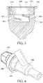
- FIG. 3shows a cross-sectional view along line A-A of the disinfecting cap of FIGS. 1-2 .
- FIG. 4shows a perspective view of the disinfecting cap of FIGS. 1-3 attached to a threaded female port of a Y-site.
- FIG. 5shows a side view of the cap and Y-site of FIG. 4 .
- FIG. 6shows a side view of a cap and Y-site in accordance with embodiments of the invention.
- FIG. 7shows a perspective view of a cap in accordance with embodiments of the invention.
- FIG. 8shows a side view of the cap of FIG. 7 .
- FIG. 9shows a perspective view of the disinfecting cap of FIGS. 7-8 attached to a threaded female port of a Y-site.
- FIG. 10shows a perspective view of a cap in accordance with embodiments of the invention.
- FIG. 11shows another perspective view of the cap of FIG. 10 .
- FIG. 12shows a side view of the cap of FIGS. 10-11 .
- FIG. 13shows a view of the proximal end of the cap of FIGS. 10-11 .
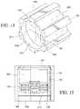
- FIG. 14shows a perspective view of a cap in accordance with embodiments of the invention.
- FIG. 15shows a side view of the cap of FIG. 14 .
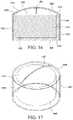
- FIG. 16shows a cross-sectional view of a cap in accordance with embodiments of the invention.
- FIG. 17shows a perspective view of the cap of FIG. 16 .
- FIG. 18shows a perspective view of a cap having a retention mechanism in accordance with embodiments of the invention.
- FIG. 19shows a view of the proximal end of the cap of FIG. 18 .
- FIG. 20shows a perspective view of a cap having a further retention mechanism in accordance with embodiments of the invention.
- FIG. 21shows a view of the proximal end of the cap of FIG. 20 .
- FIG. 22shows a perspective view of disinfecting cap in accordance with embodiments of the invention.
- FIG. 23shows a second perspective view of the disinfecting cap of FIG. 22 .
- FIG. 24shows a view of the proximal end of the cap of FIG. 22 .
- FIG. 25shows a cross-sectional view along line B-B of the disinfecting cap of FIG. 22 .
- FIG. 26shows a side view of the cap of FIG. 22 .
- FIG. 27shows a perspective view of disinfecting cap in accordance with embodiments of the invention.
- FIG. 28shows a view of the proximal end of the cap of FIG. 22 .
- FIG. 29shows a perspective view of disinfecting cap in accordance with embodiments of the invention.
- FIG. 30shows a second perspective view of the disinfecting cap of FIG. 29 .
- FIG. 31shows a view of the proximal end of the cap of FIG. 29 .
- FIG. 32shows a side view of the disinfecting cap of FIG. 29 .
- FIG. 33shows a side view of the disinfecting cap of FIG. 29 attached to a threaded female port of a Y-site.
- FIG. 34shows a perspective view of disinfecting cap in accordance with embodiments of the invention.
- FIG. 35shows a view of the proximal end of the cap of FIG. 34 .
- FIG. 36shows a perspective view of disinfecting cap in accordance with embodiments of the invention.
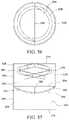
- FIG. 37shows a perspective view of disinfecting cap in accordance with embodiments of the invention.
- FIG. 38shows a top view of the disinfecting cap of FIG. 37 .
- FIG. 39shows a side view of the disinfecting cap of FIG. 37 .
- FIG. 40shows a perspective view of disinfecting cap in accordance with embodiments of the invention.
- FIG. 41shows a view of the proximal end of the cap of FIG. 40 .
- FIG. 42shows a side view of the cap of FIG. 40 .
- FIG. 43shows a perspective view of disinfecting cap in accordance with embodiments of the invention.
- FIGS. 44A and 44Bshow a bottom view of the disinfecting cap of FIG. 43 .
- FIG. 45shows a cross-sectional view of the disinfecting cap of FIG. 43 .
- FIG. 46shows a side view of disinfecting cap in accordance with embodiments of the invention.
- FIG. 47shows a perspective view of disinfecting cap in accordance with embodiments of the invention.
- FIG. 48shows a perspective view of disinfecting cap in accordance with embodiments of the invention.
- FIG. 49shows a side view of the disinfecting cap of FIG. 48 .
- FIG. 50shows a perspective view of disinfecting cap in accordance with embodiments of the invention.
- FIG. 51shows a second perspective view of the disinfecting cap of FIG. 50 .
- FIG. 52shows a view of the proximal end of the cap of FIG. 50 .
- FIG. 53shows a cross-sectional view along line C-C of the disinfecting cap of FIG. 50 .
- FIG. 54shows a side view of the cap of FIG. 50 .
- FIG. 55shows a perspective view of disinfecting cap in accordance with embodiments of the invention.
- FIG. 56shows a view of the proximal end of the cap of FIG. 55 .
- FIG. 57shows an end view of the cap of FIG. 55 .
- FIG. 58shows a perspective view of disinfecting cap in accordance with embodiments of the invention.
- FIG. 59shows a view of the proximal end of the cap of FIG. 58 .
- FIG. 60shows a cross-sectional view along line D-D of the disinfecting cap of FIG. 58 along with a cross-sectional view of a Y-site having a threaded female port.
- FIG. 61shows a perspective view of disinfecting cap in accordance with embodiments of the cap shown in FIG. 58 at a subsequent stage of use.
- FIG. 62shows a cross-sectional view along line D-D of the disinfecting cap of FIG. 61 along with a cross-sectional view of a Y-site having a threaded female port.
- FIG. 63shows a perspective view of disinfecting cap in accordance with embodiments of the cap shown in FIG. 61 at a subsequent stage of use.
- FIG. 64shows a cross-sectional view along line D-D of the disinfecting cap of FIG. 63 along with a cross-sectional view of a Y-site having a threaded female port.
- FIG. 65shows a perspective view of disinfecting cap in accordance with embodiments of the cap shown in FIG. 63 at a subsequent stage of use.
- FIG. 66shows a cross-sectional view along line D-D of the disinfecting cap of FIG. 67 along with a cross-sectional view of a Y-site having a threaded female port.
- proximal and distalare used throughout this application when describing various embodiments. These terms are not intended to be limiting and are merely provided for ease of maintaining a consistent orientation when describing various embodiments. As used herein, proximal refers to the direction generally closer to the patient and/or medical device to be cleaned and distal refers to the direction generally farther from the patient and/or medical device to be cleaned.
- a device for cleaning medical implementsin particular a device for cleaning vascular or other fluid access sites.
- Various embodiments of the inventioninclude a cap having an opening to receive an access site.
- illustrative embodimentsrefer to use of a cap to engage with a “port” as an example of such an access site.
- the inventionmay also be used in conjunction with other access sites or other medical devices without access sites.
- the healthcare workermay, with gloved hands, open the cap packaging and place the cap over the port of a medical implement to be cleaned.
- the heathcare workermay wipe the site by either applying a turning motion or by simply pushing the cap onto the port. The cap could then remain secured in place by threads other mechanisms described herein.
- a cap in place on a medical implementmay be a positive indication that a desired site of the medical implement is clean.
- a vibrant color or other indiciamay be used to allow instant visualization of a cap's presence from a door or hallway.
- Embodiments of the cap described hereinmay include a disinfecting substance, such as a solution of a suitable microbiocide or germicide.
- the disinfecting substancecan include an anti-bacterial disinfectant of any suitable type and suitable amount depending upon the size and structure of the cap.
- the disinfecting substancemay be an aqueous solution including about two percent (2%) chlorhexidine gluconate (chlorhexidine solution, “CHG”).
- CHGchlorhexidine solution
- IPAisopropyl alcohol
- IPAisopropyl alcohol
- IPAisopropyl alcohol
- IPAisopropyl alcohol
- a solution including about 70 percent (70%) IPA and about two percent (2%) CHG in an aqueous solutionis included in the disinfecting substance.
- the concentration of IPAcan vary from about 60 percent (60%) to about 90 percent (90%) and the concentration of CHG can vary from about one percent (1%) to about five percent (5%), in one embodiment.
- Suitable solution compositions and concentrationsare also possible.
- povidone iodine, polyhexanide (polyhexamethylene biguanide, “PHMB”), benzalkonium chloride (“BAC”), chlorxylenol (“PCMX”) or hydrogen peroxide solutionscan be included in the disinfecting substance of further embodiments.
- PHMBpolyhexamethylene biguanide
- BACbenzalkonium chloride
- PCMXchlorxylenol
- hydrogen peroxide solutionscan be included in the disinfecting substance of further embodiments.
- reference to one or more of these disinfecting substances in relation to a cap embodimentshould be understood to disclose the use of any other appropriate disinfecting substance as disclosed herein or as would be understood by one of ordinary skill in the art.
- embodiments of the disinfecting substancemay be in a liquid or a gel form.
- the portcomes in contact with the disinfecting substance in liquid or gel form, or with an absorbent material infused with the disinfecting substance.
- the surface of the portmay not be necessary for the surface of the port to contact the liquid or gel disinfecting substance.
- IPAis used as part of a disinfecting solution
- IPA vapors trapped within the capmay act as a disinfectant for the port without requiring contact between the liquid solution and the site being cleaned.
- PUpolyurethane
- PPpolypropylene
- TPEthermoplastic elastomer
- Sanopreneany material that could be substituted for the disclosed material.
- foam materialmay be formed of polyurethane (“PU”) or another appropriate absorbent material.
- PUpolyurethane
- other absorbent materialsmay be used in place of foam, including for example, a felted non-woven or other fibrous materials.
- FIGS. 1-3show an illustrative disinfecting cap in accordance with embodiments of the invention.
- the cap 1002is molded from PP.
- the capincludes an opening 1004 with a peripheral lip 1006 .
- the opening 1004provides access to a first cavity 1008 and a second cavity of smaller diameter 1010 extends from a base 1012 of the first cavity 1008 .
- the capmay include ribs 1022 formed on an exterior surface to provide easier handling and twisting of the cap by a healthcare worker.
- a foam ring 1014is positioned within the first cavity 1008 .
- the foam ring 1014has a central bore 1016 extending through the ring.
- the central bore 1016has a diameter that is smaller than the diameter of the second cavity 1010 .
- the foam ring 1014includes notches 1024 formed at intervals around the periphery of the ring, and the ring may be infused with a disinfecting solution.
- the second cavity 1010includes threads 1020 formed on the inside diameter 1018 of the cavity.
- the cap 1002may be attached to the threaded female port of a Y-site 1026 .
- the female portis inserted through the bore 1016 of the foam ring 1014 .
- the foam ringthereby wipes the outside surface of the port and applies a disinfecting solution.
- Threads 1028 formed on an outside diameter of the female port 1026engage with the interior threads 1020 of the second cavity 1010 , securing the cap to the port.
- the second cavity 1010may have a depth such that the female port or its threads bottom out in the cavity before the cap 1002 contacts other portions of the Y-site.
- the second cavity 1010may be deeper such that the cap contacts the second port 1030 of the Y-site or such that a shoulder 1032 of the female port contacts the base 1012 of the first cavity surrounding the diameter of the second cavity.
- FIGS. 7-9show an illustrative disinfecting cap in accordance with embodiments of the invention.
- the cap 1102may be molded from PP or another appropriate material.
- the capincludes an open proximal end 1104 and a closed distal end 1106 .
- the cap 1102may include ribs 1126 formed on an exterior surface to provide easier handling and twisting of the cap by a healthcare worker.
- the ribsmay extend parallel to a central axis of the cap, as illustrated, or may have another configuration. Alternatively, other knurling, texturing, finger shaped or grip elements may be provided.
- the proximal endhas an opening 1108 that provides access to a cavity 1110 .
- the cavity 1110has a proximal section 1112 and a distal section 1114 .
- the distal section 1114may include threads 1116 formed on its interior diameter.
- a foam ring 1118is inserted into the proximal cavity section 1112 .
- the foam ring 1118has a central bore 1120 extending through the ring.
- the ring 1118extends a distance into the cavity 1110 , but stops short of the threads 1116 .
- the ringmay be infused with a disinfecting solution.
- the cap 1102may be attached to the threaded female port of a Y-site 1122 .
- the female port of the Y-siteis inserted through the bore 1120 of the foam ring 1118 .
- the foam ringthereby wipes the outside surface of the port and applies a disinfecting solution.
- Threads 1124 formed on an outside diameter of the female port 1122engage with the interior threads 1116 of the distal cavity 1114 , securing the cap to the port.
- FIGS. 10-13show an illustrative disinfecting cap in accordance with embodiments of the invention.
- the cap 1202may be molded from PP or another appropriate material.
- the capincludes an open proximal end 1204 and a closed distal end 1206 .
- the cap 1202may include ribs 1226 formed on an exterior surface to provide easier handling and twisting of the cap by a healthcare worker.
- the ribsmay extend parallel to a central axis of the cap, as illustrated, or may have another configuration. Alternatively, other knurling, texturing, finger shaped or grip elements may be provided.
- the proximal endhas an opening 1208 that provides access to a cavity 1210 .
- the cavity 1210includes a generally cylindrical interior surface 1212 .
- the interior surfacemay be a conical section such that the diameter is larger adjacent to the opening 1208 than it is at the closed, distal end 1214 of the cavity.
- the interior surface 1212is divided into sections, with each section encompassing at least a portion of the cylindrical surface.
- the sectionsinclude one or more foam sections 1216 and one or more thread sections 1218 .
- Slots 1228are formed in the foam sections 1218 .
- the slots 1228may extend generally parallel to a central axis of the cap.
- Foam pieces 1230are inserted into the cavity 1208 along foam sections 1216 of the interior surface.
- the foam piecesextend around the circumference of the cavity along the foam sections thereby forming a broken ring extending around at least a portion of the cavity interior circumference.
- a finger 1232 formed on an outer surface of each foam pieceengages the slot 1228 and serves to hold the foam piece in place.
- the foam piecemay be formed in a pre-curved manner or may take on a curved shape as a result of being installed against the curved circumference of the cavity.
- the foam piecemay be infused with a disinfecting solution.
- Threads 1234are formed on the interior circumference of the thread sections 1218 .
- the cap 1202may be attached to the threaded female port of a Y-site (not shown).
- the female port of the Y-siteis inserted through into the cavity 1208 , and threads formed on an outside diameter of the female port engage with the interior threads 1234 of the distal cavity, securing the cap to the port.
- the surface of the portpasses over the foam pieces thereby wiping the outside surface of the port and applying a disinfecting solution.
- FIGS. 14-15show an illustrative disinfecting cap in accordance with embodiments of the invention.
- the cap 1302may be molded from PP or another appropriate material.
- the capincludes an open proximal end 1304 and a closed distal end 1306 .
- the cap 1302may include ribs 1326 formed on an exterior surface to provide easier handling and twisting of the cap by a healthcare worker.
- the ribsmay extend parallel to a central axis of the cap, as illustrated, or may have another configuration. Alternatively, other knurling, texturing, finger shaped or grip elements may be provided.
- the proximal endhas an opening 1308 that provides access to a cavity 1310 .
- the cavity 1310includes a generally cylindrical interior surface 1312 .
- the interior surfacemay be a conical section such that the diameter is larger adjacent to the opening 1308 than it is at the closed, distal end 1306 of the cavity.
- Threads 1316are formed on the cavity interior surface 1312 and spaced some distance from the distal end 1306 of the cap.
- a seal 1318is positioned across the opening 1308 of the cavity 1310 .
- the sealmay be positioned adjacent to the proximal end 1304 of the cavity or may be spaced some distance into the cavity, leaving a space 1320 between the seal and the cap end.
- the space 1322 within the cavity that is enclosed by the seal 1318may be at least partially filed with IPA.
- the sealmay include perforations 1324 , score lines or other features to aid in fracturing the seal.
- the cap 1302may be attached to the threaded female port of a Y-site (not shown).
- the female port of the Y-siteis inserted through into the cavity 1308 , and threads formed on an outside diameter of the female port engage with the interior threads 1316 of the cavity, securing the cap to the port.
- the perforated sealbreaks away under pressure from the port.
- the port surfacesare thereby exposed to liquid or vapor IPA.
- FIGS. 16-17show an illustrative disinfecting cap in accordance with embodiments of the invention.
- the cap 1402may be formed of PP or another plastic.
- the capincludes side a generally cylindrical sidewall 1404 .
- the capincludes an open proximal end 1406 and a closed distal end 1408 and encompasses a cavity 1410 .
- the cap 1402may include ribs (not shown) formed on an exterior surface to provide easier handling and twisting of the cap by a healthcare worker.
- the ribsmay extend parallel to a central axis of the cap, as illustrated in other embodiments, or may have another configuration. Alternatively, other knurling, texturing, finger shaped or grip elements may be provided.
- the capfurther includes a diaphragm valve 1414 that covers the open end 1406 of the cavity 1410 .
- the valvecovers a proximal end 1418 of sidewall 1404 as well as the open end 1416 of the cavity 1410 .
- a portion 1422 of the diaphragm valve 1414may extend beyond the opening along an outside surface 1420 of sidewall 1404 .
- the valvemay be molded over the sides and open end of the cap.
- the diaphragm valveincludes a slit 1424 . A female port or other access site is pushed through the slit 1424 into the cavity 1410 . The diaphragm valve secures the end of the port in the cavity once the port passes through the slit.
- a portion of the cavity 1410may be filled with IPA or another disinfecting substance in liquid or gel form.
- at least a portion of the cavitymay be filled with a foam, such as an open cell PU foam 1426 .
- the foammay be infused with a disinfecting substance.
- FIGS. 18-19show an illustrative disinfecting cap having a retention mechanism in accordance with embodiments of the invention.
- Various embodiments of the invention as described in this applicationmake use of threads formed on the outside of the site to be disinfected in order to secure the cap to the site.
- the present inventionalso contemplates the use of alternative securement mechanisms as illustrated, for example, in FIGS. 18-19 .
- the cap 1502an open proximal end 1504 and a closed distal end 1506 .
- the cap 1502may include ribs 1526 or other grip elements.
- the proximal endhas an opening 1508 that provides access to a cavity 1510 .
- the cavity 1510includes a generally cylindrical interior surface 1512 . Though, the interior surface may be a conical section such that the diameter is larger adjacent to the opening 1508 than it is at the closed, distal end 1504 of the cavity.
- the interior surfaceAdjacent the opening 1508 , the interior surface includes a series of stepped counterbores 1514 , 1516 , 1518 . Each successive counterbore has a small diameter than the previous. Accordingly, as illustrated in FIG. 18 , the proximal counterbore 1514 adjacent to the opening has a first diameter, the next counterbore 1516 has a second small diameter and so on until the diameter of the interior surface 1512 is reached.
- the illustrative embodimentshows three different counterbores, but more or fewer could be used.
- the counterbores 1514 , 1516 , 1518are sized to engage a thread, shoulder or other portion of the site with a friction fit.
- the counterboresmay provide clearance for a shoulder of the site so that interior surface 1512 may have an appropriate diameter to engage the threads of a port with a friction fit.
- FIGS. 20-21show an illustrative disinfecting cap having an alternative retention mechanism in accordance with embodiments of the invention.
- the cap 1602an open proximal end 1604 and a closed distal end 1606 .
- the cap 1602may include ribs 1626 or other grip elements.
- the proximal endhas an opening 1608 that provides access to a cavity 1610 .
- the cavity 1610includes a generally cylindrical interior surface 1612 . Though, the interior surface may be a conical section such that the diameter is larger adjacent to the opening 1608 than it is at the closed, distal end 1604 of the cavity.
- Retention elements 1614extend from the interior surface 1612 . As illustrated in FIGS. 20-21 , these elements are arranged in three columns 1616 a , 1616 b , 1616 c spaced evenly around the interior surface. Though, more or fewer may be used. Within each column, a series of retention elements 1614 a , 1614 b , 1614 c extends longitudinally into the cavity 1610 along the interior surface 1612 . Arranged in this manner, the retention elements engage with the threads or other features of the port to be cleaned and retain the cap on the port. I
- the retention elementsmay be formed in a resilient manner such that the cap can be pushed onto the port. As the threads of the port are pushed past each retention element, that element allows the thread to pass and then rebounds into a position in which the retention element engages the thread and retains the cap.
- the capmay be screwed onto the port such that the retention elements engage the threads.
- the exemplary embodiment discussed hereincontemplates arranging the retention elements 1614 in a certain pattern, particularly in equally columns of retaining elements.
- the retaining elementscould be arrange in any other possible patterns, including, among others, in a spiral pattern or a spaced matrix.
- FIGS. 22-25show an illustrative disinfecting cap in accordance with embodiments of the invention.
- the cap 1702is molded from PU and may be reaction injection molded from PU foam into the final shape.
- the molded foam 1740may include a skin 1742 that is resistant to IPA or other disinfecting solutions.
- the capincludes an open proximal end 1704 and a closed distal end 1706 .
- the cap 1702may include ribs 1726 formed on an exterior surface to provide easier handling and twisting of the cap by a healthcare worker.
- the ribsmay extend parallel to a central axis of the cap, as illustrated, or may have another configuration. Alternatively, other knurling, texturing, finger shaped or grip elements may be provided.
- the proximal endhas an opening 1708 that provides access to a main cavity 1710 .
- the cavity 1710has a generally cylindrical sidewall 1712 and distal or bottom surface 1714 .
- Threads 1716may be formed on the sidewall in order to engage with the threads of a site to be cleaned and to retain the cap on the site.
- the cylindrical sidewallmay have a constant diameter along a longitudinal axis of the cap or the diameter may increase along the longitudinal axis such that the diameter of the sidewall is greater at the distal end than the diameter of the sidewall at the proximal end at or near the bottom surface 1714 in one embodiment. In another embodiment the diameter may decrease along the longitudinal axis such that the diameter of the sidewall is smaller at the distal end than the diameter of the sidewall at the proximal end at or near the bottom surface 1714 .
- One or more depressions, cavities or holes 1718are formed extending into the cap from the distal surface 1714 of the cavity 1710 . These holes 1718 are at least partially filled with and serve as reservoirs to retain a disinfecting solution such as liquid or gel ISA.
- a disinfecting solutionsuch as liquid or gel ISA.
- the cap 1702may include a peelable lid 1720 that is sealed to the skin 1742 of the cap in order to retain the disinfecting solution within the cap cavity 1710 , thereby preventing the disinfecting solution from leaking or evaporating out from the cap 1702 .
- the holes 1718may be generally cylindrical in shape and may be arranged in any appropriate pattern. Alternatively, the holes may be formed in other shapes.
- FIGS. 27-28show an illustrative embodiment of a cap 1802 that has similarities to the embodiment of FIGS. 22-26 in which the holes 1818 are spaced farther from sidewall 1812 and are generally rectangular in profile.
- the holesmay be formed with a constant cross-section as illustrated in FIGS. 24-25 and 28 , or the holes may have a different cross-section.
- the holesmay have a conical or pyramid shape such that the opening 1728 adjacent to the distal surface 1714 , 1814 of the cavity 1710 , 1810 has a greater cross-sectional area than the bottom 1724 of the hole 1718 .
- the holemay have an undercut such that the opening adjacent to the distal surface 1714 , 1814 of the cavity 1710 , 1810 has a smaller cross-sectional area than the bottom 1724 of the hole 1718 .
- the shape or geometry of the holemay be such that the surface tension (cohesion and adhesion) of the disinfecting solution is held inside the hole below the distal surface 1714 , 1814 without the need for a cover or other retaining mechanism.
- the disinfecting solution in the capfills the individual cavities 1718 as well as at least a portion of the main cavity 1710 .
- a cap having this configurationnamely multiple cavities in the bottom surface in conjunction with a main cavity, causes the cap to significantly retain a greater volume of solution, particularly when inverted than is achieved with a cap having a single main cavity portion. This allows the cap to be inverted when being installed on a port while still retaining a sufficient volume of solution. Such a cap retains sufficient solution even when the cap is shaken. This result is found both in caps that employ internal threads and in caps that do not have threads but rather use a constant diameter cylindrical sidewall cavity that engages the port by a friction fit.
- honeycomb structureretains 50% more IPA while inverted than a cap without honeycomb or some other fluid retention mechanism.
- the honeycombwas able to retain 70% of the inverted IPA following vigorous shaking.
- FIGS. 29-32show an illustrative disinfecting cap in accordance with embodiments of the invention.
- the capincludes an open proximal end 1904 and a closed distal end 1906 .
- the cap 1902may include ribs 1926 formed on an exterior surface to provide easier handling and twisting of the cap by a healthcare worker.
- the ribsmay extend parallel to a central axis of the cap, as illustrated, or may have another configuration. Alternatively, other knurling, texturing, finger shaped or grip elements may be provided.
- the proximal endhas an opening 1908 that provides access to a cavity 1910 .
- the cavity 1910has a generally cylindrical sidewall 1912 and distal or bottom surface 1914 .
- Threads 1916may be formed on the sidewall in order to engage with the threads of a site to be cleaned and to retain the cap on the site.
- the threadsmay extend completely around the internal circumference of the inner cavity, they may extend partially around, or they may extend greater than once around the entire internal circumference.
- One or more depressions, cavities or holes 1918are formed extending into the cap from the distal surface 1914 of the cavity 1910 . These holes 1918 are at least partially filled with and serve as reservoirs to retain a disinfecting solution such as liquid or gel ISA.
- the holes 1918may be generally cylindrical in shape and may be arranged in any appropriate pattern. Alternatively, the holes may be formed in other shapes.
- the holesmay be formed with a constant cross-section as illustrated in FIGS. 31-32 , or the holes may have a different cross-section.
- the holesmay have a conical or pyramid shape such that the opening 1928 adjacent to the distal surface 1914 of the cavity 1910 has a greater cross-sectional area than the bottom 1924 of the hole 1918 .
- the holemay have an undercut such that the opening 1928 adjacent to the distal surface 1914 of the cavity 1910 has a smaller cross-sectional area than the bottom 1924 of the hole 1918 .
- the shape or geometry of the holemay be such that the surface tension (cohesion and adhesion) of the disinfecting solution is held inside the hole below the distal surface 1914 without the need for a cover or other retaining mechanism when the cap is in use.
- the capmay include a peelable lid 1950 or other packaging.
- a portion 1952 of the lid 1950extends into the cavity 1910 of the cap 1902 .
- An inside surface of the extending portion 1952 of the lidmay seal against the bottom surface of the cavity 1910 to retain the disinfecting solution in the holes until the cap is used.
- the cap 1902may be attached to the threaded female port of a Y-site 1930 .
- the female port of the Y-siteis inserted into the cavity 1910 of the cap.
- Threads 1932 formed on an outside diameter of the female port 1930engage with the interior threads 1916 , securing the cap to the port.
- the end surface 1934 of the siteWhen inserted into the cap, the end surface 1934 of the site may come in contact with the distal surface 1914 of the cavity 1910 such that the site is wetted by the disinfecting solution. As the face 1934 of the connector engages the bottom surface 1914 of the cavity 1910 , the bottom surface 1914 and hole openings 1928 are distorted and disinfecting solution releases from the holes 1918 as the holes deform and lose their full volume.
- the material of the entire cap or of only a section surrounding the holes 1918 at the bottom of the cavity 1910may be soft or hard plastic, such as polypropylene (PP) or santoprene or other thermoplastic elastomers (TPE).
- PPpolypropylene
- TPEthermoplastic elastomers
- the surface of the sitemay remain spaced from the distal surface such that disinfecting is provided by disinfecting solution vapor contained within the cap.
- FIGS. 34-35show an illustrative embodiment of a cap 2002 that has similarities to the embodiment of FIGS. 29-33 in which the holes 2018 are formed as a honeycomb 2048 rather than as individual cavities.
- FIGS. 40-42show a further illustrative embodiment of a cap 2802 that has similarities to the embodiment of FIGS. 34-35 .
- the capincludes an open proximal end 2804 and a closed distal end 2806 .
- the cap 2802may include ribs 2826 formed on an exterior surface to provide easier handling and twisting of the cap by a healthcare worker.
- the ribsmay extend parallel to a central axis of the cap, as illustrated, or may have another configuration.
- other knurling, texturing, finger shaped or grip elementsmay be provided.
- the proximal endhas an opening 2808 that provides access to a cavity 2810 .
- the cavity 2810has a generally cylindrical sidewall 2812 and distal or bottom surface 2814 .
- Threads 2816may be formed on the sidewall in order to engage with the threads of a site to be cleaned and to retain the cap on the site.
- the threadsmay extend completely around the internal circumference of the inner cavity, they may extend partially around, or they may extend greater than once around the entire internal circumference. In the illustrative embodiment, the threads are shown extending up to the surface of the proximal end 2804 of the cap.
- Hexagonal cavities or holes 2818 similar to a honeycombare formed extending into the cap from the distal surface 2814 of the cavity 2810 . These holes 2818 are at least partially filled with and serve as reservoirs to retain a disinfecting solution such as liquid or gel ISA.
- the holesmay be formed with a constant cross-section as illustrated in FIGS. 40-42 , or the holes may have a varying cross-section.
- the holesmay have a conical or hexagonal-pyramid shape such that the opening 2828 adjacent to the distal surface 2814 of the cavity 2810 has a greater cross-sectional area than the bottom 2824 of the hole 2818 .
- the holemay have an undercut such that the opening 2828 adjacent to the distal surface 2814 of the cavity 2810 has a smaller cross-sectional area than the bottom 2824 of the hole 2818 .
- the shape or geometry of the holemay be such that the surface tension (cohesion and adhesion) of the disinfecting solution is held inside the hole below the distal surface 2814 without the need for a cover or other retaining mechanism when the cap is in use.
- FIGS. 37-39show an illustrative disinfecting cap in accordance with embodiments of the invention.
- the cap 2102includes a lanyard 2104 that can be used to hang or otherwise attaché the cap to the port or access site to be cleaned.
- the lanyardhas a loop 2106 through which the port can be inserted.
- the capmay include two cap portions 2108 , 2110 such that the cap can be used twice.
- Each cap portionhas a generally cylindrical side wall 2112 , and open end 2114 and a closed end 2116 .
- the capsare position back-to-back such that the closed end 2116 is shared.
- the cap 2102is removed from any packaging, and the first cap portion 2108 is applied to the port to be cleaned.
- the second cap portion 2110includes a sealed lid 2118 . When the healthcare worker uses the cap for a second time, the lid 2118 is removed, and the second cap portion 2110 is applied to the port to be cleaned.
- FIGS. 43-45show an illustrative disinfecting cap in accordance with embodiments of the invention.
- the cap 2402may be molded from PP or another appropriate plastic or other material.
- the capincludes an opening 2404 with a peripheral surface 2406 surrounding the opening.
- the opening 2404provides access to a cavity 2408 .
- the cap 2402may have a generally square cross-section or may include ribs formed on an exterior surface to provide easier handling and twisting of the cap by a healthcare worker.
- the ribsmay extend parallel to a central axis of the cap or may have another configuration. Alternatively, other knurling, texturing, finger shaped or grip elements may be provided.
- the cavity 2408has a generally cylindrical sidewall 2412 and distal or bottom surface 2414 .
- Retention elements 2410extend from the interior surface 2412 .
- the retention elementsmay be formed in a resilient manner such that the cap can be pushed onto the port. As the threads of the port are pushed past each retention element, that element allows the thread to pass and then rebounds into a position in which the retention element engages the thread and retains the cap. Alternatively, the cap may be screwed onto the port such that the retention elements engage the threads.
- the retaining elements 2410could be arrange in any number of possible patterns, including, among others, in columns, rows a spiral pattern or a spaced matrix.
- threadsmay be formed on the sidewall in order to engage with the threads of a site to be cleaned and to retain the cap on the site.
- the cylindrical sidewallmay have a constant diameter along a longitudinal axis of the cap or the diameter may increase along the longitudinal axis such that the diameter of the sidewall is greater at the proximal end than the diameter of the sidewall at the distal end at or near the bottom surface 2414 in one embodiment. In another embodiment the diameter may decrease along the longitudinal axis such that the diameter of the sidewall is smaller at the proximal end than the diameter of the sidewall at the distal end at or near the bottom surface 2414 .
- the cap 2402may include an aperture 2416 adjacent the bottom or distal end of the cap.
- the aperturemay be sized to accept the thumb pad 2418 attached to the plunger actuating shaft 2420 of a syringe (not shown).
- the bottom surface 2424 enclosing the aperture 2416may include a slot 2422 that is of an appropriate size to accommodate a rib 2426 of the syringe plunger shaft 2420 .
- An absorbent material 2430may be positioned inside the cavity 2408 .
- the absorbent materialmay be infused with a disinfecting solution.
- the disinfecting solutionmay be present in the cavity without the use of an absorbent material.
- the cap 2402may include a peelable lid 2428 that is sealed to the top surface 2406 of the cap in order to retain the disinfecting solution within the cap cavity 2408 , thereby preventing the disinfecting solution from leaking or evaporating out from the cap 2402 .
- FIG. 46shows an illustrative disinfecting cap in accordance with embodiments of the invention.
- the cap 2502includes resilient fingers 2516 extending from a bottom surface 2524 of the cap.
- One or more slots 2522may extend vertically between the resilient fingers 2516 so that the fingers can flex outward to accommodate the thumb pad 2518 attached to the plunger actuating shaft 2520 of a syringe 2532 .
- the fingers 2516may include a notch or groove 2534 in which the thumb pad seats when the cap is installed.
- the opening 2504 of the capis positioned on the distal end 2536 of the cap away from the syringe 2532 .
- FIG. 47shows an illustrative disinfecting cap in accordance with embodiments of the invention.
- the cap 2602may be formed of a soft or flexible material.
- the capincludes a lip 2616 that is stretched to extend around at least a portion of the diameter of the thumb pad 2618 attached to the plunger actuating shaft 2620 of a syringe (not shown).
- the cap 2602includes a cavity 2608 having an opening 2604 and a closed end 2614 .
- a top surface 2606 of the cap surrounding the opening 2604is positioned adjacent the surface of the thumb pad 2618 . In this manner, the thumb pad may act to seal the cavity 2608 in order to retain the disinfecting solution within the cap cavity.
- the cap 2702may include a clip 2716 .
- the clipmay include resilient arms 2718 that are sized to releasably engage the barrel 2734 of a syringe 2732 .
- An absorbent material 2730may be positioned inside the cavity 2408 .
- the absorbent materialmay be infused with a disinfecting solution.
- the disinfecting solutionmay be present in the cavity without the use of an absorbent material.
- the cap 2702may include a peelable lid 2728 that is sealed to the top surface 2706 of the cap in order to retain the disinfecting solution within the cap cavity 2708 , thereby preventing the disinfecting solution from leaking or evaporating out from the cap 2702 .
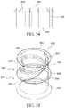
- FIGS. 50-53show an illustrative disinfecting cap in accordance with embodiments of the invention.
- the cap 2202is molded from PU and may be reaction injection molded from PU foam into the final shape.
- the molded foam 2240may include a skin 2242 that is resistant to IPA or other disinfecting solutions.
- the capincludes an open proximal end 2204 and a closed distal end 2206 .
- the cap 2202may include ribs 2226 formed on an exterior surface to provide easier handling and twisting of the cap by a healthcare worker.
- the ribsmay extend parallel to a central axis of the cap, as illustrated, or may have another configuration. Alternatively, other knurling, texturing, finger shaped or grip elements may be provided.
- the proximal endhas an opening 2208 that provides access to a cavity 2210 .
- the cavity 2210has a generally cylindrical sidewall 2212 and distal or bottom surface 2214 .
- the cylindrical sidewall 2212may have a constant diameter along a longitudinal axis of the cap or the diameter may increase along the longitudinal axis such that the diameter of the sidewall is greater at the distal end than the diameter of the sidewall at the proximal end at or near the bottom surface 2214 in one embodiment. In another embodiment the diameter may decrease along the longitudinal axis such that the diameter of the sidewall is smaller at the distal end than the diameter of the sidewall at the proximal end at or near the bottom surface 2214 .
- Embodiments of the capmay include a valve 2230 .
- the valvemay be a “duckbill,” diaphragm or other type of self-sealing valve.
- the valve 2230includes a lip 2232 that extends over a top surface 2234 of the cavity sidewall 2236 .
- the sidewall 2236may include a counterbore 2238 or recess to accommodate the lip 2232 such that a proximal surface of the lip is flush with a proximal surface of the cap.
- a portion 2244 of the valve 2230extends distally from the lip 2232 along the inside diameter 2212 of the cavity 2210 .
- two generally planar portions 2246 of the valveextend distally at a relative angle so as to meet at an acute angle 2248 .
- a slit 2250is formed at the intersection of the two planar portions 2246 .
- a portion of the cavity 2210may be filled with IPA or another disinfecting substance in liquid or gel form.
- at least a portion of the cavitymay be filled with a foam, such as an open cell PU foam.
- the foammay be infused with a disinfecting substance.
- the valvemay operate to secure the cap to the port and may also prevent or reduce leaking of disinfecting solution out of the cap.
- the cap 2202may include a peelable lid 2220 that is sealed to the skin 1742 of the cap in order to retain the disinfecting solution within the cap cavity 2210 , thereby preventing the disinfecting solution from leaking or evaporating out from the cap 2202 .
- FIGS. 55-57show an illustrative disinfecting cap in accordance with embodiments of the invention.
- the cap 2302includes a first engaging portion 2330 and a second reservoir portion 2370 .
- the engaging portion 2330includes side a generally cylindrical sidewall 2338 .
- the engaging portionincludes an open proximal end 2334 and an open distal end 2336 and encompasses a cavity 2342 .
- Threads 2340may be formed on the sidewall in order to engage with the threads of a site to be cleaned and to retain the cap on the site.
- the cylindrical sidewallmay have a constant diameter along a longitudinal axis of the cap or the diameter may increase along the longitudinal axis such that the diameter of the sidewall is greater at the proximal end 2334 than the diameter of the sidewall at the distal end 2336 .
- the diametermay decrease along the longitudinal axis such that the diameter of the sidewall is smaller at the proximal end 2334 than the diameter of the sidewall at the distal end 2336 .
- the cap 2302may include ribs (not shown) formed on an exterior surface to provide easier handling and twisting of the cap by a healthcare worker.
- the ribsmay extend parallel to a central axis of the cap, as illustrated, or may have another configuration. Alternatively, other knurling, texturing, finger shaped or grip elements may be provided.
- the engaging portion 2330includes a diaphragm valve 2344 that covers the distal end 2336 of the cavity 2342 .
- the valvemay cover a distal end 2346 of sidewall 2338 as well as the open end 2336 of the cavity 2342 .
- a portion 2348 of the diaphragm valve 2344may extend beyond the opening along an outside surface 2350 of sidewall 2338 .
- the valvemay be molded over the sides and open end of the engaging portion.
- the diaphragm valve 2344includes a slit 2352 .
- a female port or other access siteis pushed through the slit 2350 into the cavity 2342 as the threads 2340 of the cavity engage the threads of the port.
- the diaphragm valvemay secure the end of the port in the cavity once the port passes through the slit.
- the cap 2302further includes a reservoir portion 2370 .
- the reservoir portionhas an open proximal end 2372 and a closed distal end 2374 .
- a generally cylindrical sidewall 2378encompasses a cavity 2376 .
- the reservoir portionmay be sonically welded or otherwise attached to the engaging portion.
- a portion of the cavity 2376may be filled with IPA or another disinfecting substance in liquid or gel form.
- at least a portion of the cavitymay be filled with a foam, such as an open cell PU foam.
- the foammay be infused with a disinfecting substance. Accordingly, as a female port or other access site is pushed through the slit 2352 of the engaging portion 2330 into the cavity 2376 of the reservoir portion 2370 , the port is exposed to the disinfecting substance.
- FIGS. 58-60show an illustrative disinfecting cap in accordance with embodiments of the invention.
- the cap 2902may be molded from PP.
- the capmay be molded from PU and may be reaction injection molded from PU foam into the final shape.
- the molded foammay include a skin that is resistant to IPA or other disinfecting solutions.
- the cap 2902includes an open proximal end 2904 and a closed distal end 2906 .
- the capmay include ribs 2926 formed on an exterior surface to provide easier handling and twisting of the cap by a healthcare worker.
- the ribsmay extend parallel to a central axis of the cap, as illustrated, or may have another configuration. Alternatively, other knurling, texturing, finger shaped or grip elements may be provided.
- the proximal endhas an opening 2908 that provides access to a cavity 2910 .
- the cavity 2910has a generally cylindrical sidewall 2912 and distal or bottom surface 2914 .
- Threadsmay be formed on the sidewall in order to engage with the threads of a site to be cleaned and to retain the cap on the site.
- the cylindrical sidewallmay have a constant diameter along a longitudinal axis of the cap or the diameter may increase along the longitudinal axis such that the diameter of the sidewall is greater at the proximal end than the diameter of the sidewall at the distal end at or near the bottom surface 2914 in one embodiment. In another embodiment the diameter may decrease along the longitudinal axis such that the diameter of the sidewall is smaller at the distal end than the diameter of the sidewall at the proximal end at or near the bottom surface 2914 .
- the cap 2902may also include a separating disc or screen 2918 .
- the illustrative screen 2918has a generally cylindrical disc/flat circular shape with an outside diameter 2920 that corresponds across at least part of its perimeter to the sidewall 2912 of the cavity 2910 .
- the screen 2918divides the cavity 2910 into two portions, a proximal portion 2922 adjacent to the opening 2908 and a distal portion 2924 adjacent to the bottom surface 2914 of the cavity.
- the distal cavity 2924may be filled at least partially with a disinfecting solution.
- the screen 2918may have one or more through holes 2928 .
- the holes 2928may be generally cylindrical in shape and may be arranged in any appropriate pattern. Alternatively, the holes may be formed in other shapes.
- the holesmay be formed with a constant cross-section as illustrated in FIGS. 58-60 , or the holes may have a different cross-section. For example, the holes may have a conical or pyramid shape.
- the sidewall 2912 of the cavity 2910may include one or more slots 2930 .
- the slotsextend parallel to a longitudinal axis of the cap.
- Ridges or arms 2932extend from the outside diameter 2920 of the screen 2918 . These arms 2932 engage with the slots 2930 in the cavity diameter and allow the screen 2918 to slide longitudinally within the cavity 2910 .
- the arms 2932may extend longitudinally above a top surface 2934 of the screen 2918 .
- FIGS. 58 and 60show the cap prior to insertion of the female port 2036 of the Y-site 2038 into the cap.
- the screenis positioned adjacent the open end 2904 of the cap such that the arms 2932 are parallel with or below the top surface 2903 of the cap.
- FIGS. 61-62show the cap 2902 at the point that the female port 2934 first makes contact with the cap.
- threads 2940 formed on an outside diameter of the female port or the distal surface 2942 of the port 2934contact the arms 2932 of the screen 2918 .
- the screen top surface 2934is spaced apart from the top surface 2903 of the cap by a first distance 2944 .
- the distal portion 2924 of the cavity 2910is at least partially filled with a disinfecting solution while the proximal portion 2922 of the cavity does not include any disinfecting solution.
- FIGS. 63-64show the cap 2902 at a point that the female port 2934 has been pushed partially within the cap.
- the screen top surface 2934is spaced apart from the top surface 2903 of the cap by a second, greater distance 2946 .
- the distal portion 2924 of the cavity 2910remains at least partially filled with a disinfecting solution, but at least a portion of the disinfecting solution has been forced through the holes 2928 into the proximal portion 2922 of the cavity.
- the disinfecting solutionwets and disinfects the surface of the female port 2934 .
- FIGS. 65-66show the cap 2902 at a point that the female port 2934 has been fully pushed into the cap.
- the screen top surface 2934is spaced apart from the top surface 2903 of the cap by a third, greater distance 2948 .
- the distal portion 2924 of the cavity 2910may be completely collapsed as shown in the illustrative embodiment.
- the distal portion of the cavitymay retain some volume that is at least partially filled with a disinfecting solution but with a significant portion of the disinfecting solution having been forced through the holes 2928 into the proximal portion 2922 of the cavity.
- the inside diameter 2912 of the cavity 2910may engage the threads 2940 of the female port 2934 with a friction fit in order to retain the cap on the port.
- the port 2934As the port 2934 is inserted into the cap, it forces the screen 2918 into the distal cavity portion 2924 , and disinfecting solution is forced through holes 2918 into the proximal cavity portion 2922 where it wets and disinfects the port.
- the disinfecting fluidmay flow through the holes such that it flows along the sidewall 2912 of the cavity and onto the port.
- the speed of inserting the portmay be such that the disinfecting fluid is forced through the holes 2918 with sufficient force to cause the disinfecting fluid to spray onto and coat the port surface.
- FIGS. 58-66provide examples in which the screen 2918 has a certain thickness between the top surface 2934 and a bottom surface.
- the screenmay have a different thickness that is thinner or thicker than the exemplary embodiment shown.
- the thickness of the screen in combination with the size and shape of the holes 2928would affect the disinfecting fluid flows or sprays onto the port surface.
- the cap 2902may include a peelable lid that is sealed to a top surface 2903 of the cap in order to retain the disinfecting solution within the cap cavity 2910 , thereby preventing the disinfecting solution from leaking or evaporating out from the cap 2902 .
Landscapes
- Health & Medical Sciences (AREA)
- Heart & Thoracic Surgery (AREA)
- Veterinary Medicine (AREA)
- Life Sciences & Earth Sciences (AREA)
- Public Health (AREA)
- General Health & Medical Sciences (AREA)
- Animal Behavior & Ethology (AREA)
- Biomedical Technology (AREA)
- Hematology (AREA)
- Pulmonology (AREA)
- Anesthesiology (AREA)
- Engineering & Computer Science (AREA)
- Epidemiology (AREA)
- Chemical & Material Sciences (AREA)
- Chemical Kinetics & Catalysis (AREA)
- General Chemical & Material Sciences (AREA)
- Apparatus For Disinfection Or Sterilisation (AREA)
Abstract
Description
Claims (20)
Priority Applications (4)
| Application Number | Priority Date | Filing Date | Title |
|---|---|---|---|
| US17/014,901US11464962B2 (en) | 2015-08-21 | 2020-09-08 | Disinfecting cap |
| US17/390,859US12083309B2 (en) | 2015-08-21 | 2021-07-30 | Disinfecting cap |
| US17/390,854US12186522B2 (en) | 2015-08-21 | 2021-07-30 | Disinfecting cap |
| US18/967,401US20250090829A1 (en) | 2015-08-21 | 2024-12-03 | Disinfecting cap |
Applications Claiming Priority (6)
| Application Number | Priority Date | Filing Date | Title |
|---|---|---|---|
| US201562208243P | 2015-08-21 | 2015-08-21 | |
| US201562208213P | 2015-08-21 | 2015-08-21 | |
| US201562208364P | 2015-08-21 | 2015-08-21 | |
| US201562216650P | 2015-09-10 | 2015-09-10 | |
| US15/240,301US10828484B2 (en) | 2015-08-21 | 2016-08-18 | Disinfecting cap |
| US17/014,901US11464962B2 (en) | 2015-08-21 | 2020-09-08 | Disinfecting cap |
Related Parent Applications (1)
| Application Number | Title | Priority Date | Filing Date |
|---|---|---|---|
| US15/240,301ContinuationUS10828484B2 (en) | 2015-08-21 | 2016-08-18 | Disinfecting cap |
Related Child Applications (2)
| Application Number | Title | Priority Date | Filing Date |
|---|---|---|---|
| US17/390,859ContinuationUS12083309B2 (en) | 2015-08-21 | 2021-07-30 | Disinfecting cap |
| US17/390,854ContinuationUS12186522B2 (en) | 2015-08-21 | 2021-07-30 | Disinfecting cap |
Publications (2)
| Publication Number | Publication Date |
|---|---|
| US20210001110A1 US20210001110A1 (en) | 2021-01-07 |
| US11464962B2true US11464962B2 (en) | 2022-10-11 |
Family
ID=58100803
Family Applications (5)
| Application Number | Title | Priority Date | Filing Date |
|---|---|---|---|
| US15/240,301Active2037-01-20US10828484B2 (en) | 2015-08-21 | 2016-08-18 | Disinfecting cap |
| US17/014,901Active2037-05-15US11464962B2 (en) | 2015-08-21 | 2020-09-08 | Disinfecting cap |
| US17/390,854Active2038-01-03US12186522B2 (en) | 2015-08-21 | 2021-07-30 | Disinfecting cap |
| US17/390,859Active2037-09-07US12083309B2 (en) | 2015-08-21 | 2021-07-30 | Disinfecting cap |
| US18/967,401PendingUS20250090829A1 (en) | 2015-08-21 | 2024-12-03 | Disinfecting cap |
Family Applications Before (1)
| Application Number | Title | Priority Date | Filing Date |
|---|---|---|---|
| US15/240,301Active2037-01-20US10828484B2 (en) | 2015-08-21 | 2016-08-18 | Disinfecting cap |
Family Applications After (3)
| Application Number | Title | Priority Date | Filing Date |
|---|---|---|---|
| US17/390,854Active2038-01-03US12186522B2 (en) | 2015-08-21 | 2021-07-30 | Disinfecting cap |
| US17/390,859Active2037-09-07US12083309B2 (en) | 2015-08-21 | 2021-07-30 | Disinfecting cap |
| US18/967,401PendingUS20250090829A1 (en) | 2015-08-21 | 2024-12-03 | Disinfecting cap |
Country Status (5)
| Country | Link |
|---|---|
| US (5) | US10828484B2 (en) |
| EP (1) | EP3337552A4 (en) |
| CN (2) | CN115607707A (en) |
| CA (1) | CA2996289A1 (en) |
| WO (1) | WO2017035014A1 (en) |
Cited By (2)
| Publication number | Priority date | Publication date | Assignee | Title |
|---|---|---|---|---|
| US20230091798A1 (en)* | 2021-09-23 | 2023-03-23 | Medline Industries, Lp | Foley Catheter System with Specimen Sampling Port Disinfectant Cap and Corresponding Tray Packaging Systems and Drainage Products |
| US12083309B2 (en) | 2015-08-21 | 2024-09-10 | Medline Industries, Lp | Disinfecting cap |
Families Citing this family (9)
| Publication number | Priority date | Publication date | Assignee | Title |
|---|---|---|---|---|
| US11421495B2 (en)* | 2014-01-28 | 2022-08-23 | Stemlock, Incorporated | Fluid release mechanism for a chemically-inflatable bag |
| MX2018008749A (en) | 2016-01-18 | 2018-11-09 | Becton Dickinson Co | Disinfection cap for iv needleless connectors. |
| CN115957431B (en)* | 2018-04-10 | 2025-08-22 | 贝克顿·迪金森公司 | Universal disposable caps for male and female connectors |
| WO2019199786A1 (en)* | 2018-04-10 | 2019-10-17 | Becton, Dickinson And Company | Universal single-use cap for male and female connectors |
| JP2022521530A (en)* | 2019-02-22 | 2022-04-08 | スリーエム イノベイティブ プロパティズ カンパニー | Disinfection device for lure actuating devices |
| US11975168B2 (en)* | 2019-11-18 | 2024-05-07 | Becton, Dickinson And Company | Disinfectant cap |
| EP4426256A4 (en)* | 2021-11-05 | 2025-08-20 | Medline Industries Lp | DISINFECTION CAP |
| US20240165389A1 (en)* | 2022-11-18 | 2024-05-23 | Becton, Dickinson And Company | Medical Device with Anti-Peeling Flash Feature |
| US20240173448A1 (en)* | 2022-11-29 | 2024-05-30 | Becton, Dickinson And Company | Combination Skin and Medical Connector Disinfecting Device |
Citations (110)
| Publication number | Priority date | Publication date | Assignee | Title |
|---|---|---|---|---|
| US877946A (en) | 1907-02-04 | 1908-02-04 | Henry Solomon Wellcome | Apparatus for containing and injecting serums and other substances. |
| US2735427A (en) | 1956-02-21 | Hypodermic syringe | ||
| US2851036A (en) | 1955-06-01 | 1958-09-09 | Lee Barry Lab Inc | Combination pre-sterilized syringe and container |
| US4243035A (en) | 1979-06-18 | 1981-01-06 | Barrett Howard G | Syringe with integral swab |
| US4317446A (en) | 1980-09-04 | 1982-03-02 | Schering Corporation | Prefilled disposable syringe |
| US4335756A (en) | 1981-01-21 | 1982-06-22 | Texas Medical Products, Inc. | Sterilized medical tubing cover |
| US4340148A (en) | 1980-10-14 | 1982-07-20 | Baxter Travenol Laboratories, Inc. | Luer cap |
| US4440207A (en) | 1982-05-14 | 1984-04-03 | Baxter Travenol Laboratories, Inc. | Antibacterial protective cap for connectors |
| US4624664A (en) | 1985-07-22 | 1986-11-25 | Travenol European Research And Development Centre (Teradec) | Antibacterial closure system |
| US4799926A (en) | 1987-10-13 | 1989-01-24 | Habley Medical Technology Corporation | Syringe, having self-contained, sterile, medication applying swab |
| US5187843A (en) | 1991-01-17 | 1993-02-23 | Lynch James P | Releasable fastener assembly |
| US5471706A (en) | 1992-12-14 | 1995-12-05 | James M. Leu | Means for cleaning of health care instruments |
| US5694978A (en) | 1994-12-09 | 1997-12-09 | Fresenius Ag | Protective cap assembly for protecting and sealing a tubing |
| US5820604A (en) | 1996-06-11 | 1998-10-13 | Endolap, Inc. | Cannula cap including yeildable outer seal and flapper valve |
| US5827244A (en) | 1992-02-18 | 1998-10-27 | Via Christi Research Inc. | Intravenous infusion system |
| US5941857A (en) | 1997-09-12 | 1999-08-24 | Becton Dickinson And Company | Disposable pen needle |
| US5989229A (en) | 1997-05-28 | 1999-11-23 | Becton, Dickinson And Company | Needle cover assembly having self-contained drug applicator |
| US6045539A (en) | 1995-02-17 | 2000-04-04 | Menyhay; Steve Z. | Sterile medical injection port and cover apparatus |
| US6126640A (en) | 1996-09-30 | 2000-10-03 | Becton, Dickinson And Company | Protective sealing barrier for a syringe |
| US6152913A (en) | 1995-04-27 | 2000-11-28 | The Kippgroup | Medical luer connection having protective cap with crush rib |
| WO2002005188A1 (en) | 2000-07-07 | 2002-01-17 | Vasca, Inc. | Apparatus and kits for locking and disinfecting implanted catheters |
| US6419825B1 (en) | 1998-11-13 | 2002-07-16 | Fresenius Medical Care Deutschland Gmbh | Closure element |
| US6592564B2 (en) | 1999-07-23 | 2003-07-15 | Vasca, Inc. | Methods and kits for locking and disinfecting implanted catheters |
| US6679870B1 (en) | 1999-07-23 | 2004-01-20 | Vasca, Inc. | Methods and kits for locking and disinfecting implanted catheters |
| US20040028877A1 (en) | 1999-07-30 | 2004-02-12 | Kawasaki Jukogyo Kabushiki Kaisha | Sandwich structure and method of repairing the same |
| US20050013836A1 (en) | 2003-06-06 | 2005-01-20 | Board Of Regents, The University Of Texas System | Antimicrobial flush solutions |
| US20050147525A1 (en) | 2004-01-06 | 2005-07-07 | Bousquet Gerald G. | Sanitized tubing termination method and assembly |
| US7282186B2 (en) | 2003-06-20 | 2007-10-16 | Lake Jr Robert F | Decontamination device |
| US20080033371A1 (en) | 2006-06-26 | 2008-02-07 | Updegraff Debra K | Cover for catheter assembly |
| US20080039803A1 (en) | 2006-08-09 | 2008-02-14 | Lawrence Allan Lynn | Luer protection pouch™ and luer valve/male luer protection method |
| US20080235888A1 (en) | 2007-04-02 | 2008-10-02 | Vaillancourt Michael J | Microbial scrub brush |
| WO2009002474A1 (en) | 2007-06-22 | 2008-12-31 | Excelsior Medical | Antiseptic cap with thread cover |
| US20090028750A1 (en) | 2007-07-23 | 2009-01-29 | Ryan Dana Wm | Cleaning and Disinfection Swabbing Device for Needle-Free Intravenous (IV) Connectors |
| US20090137969A1 (en) | 2007-11-26 | 2009-05-28 | Colantonio Anthony J | Apparatus and method for sterilizing a tubular medical line port |
| USD607325S1 (en) | 2008-09-05 | 2010-01-05 | Ivera Medical Corporation | Cleaning cap |
| US20100003067A1 (en) | 2008-07-03 | 2010-01-07 | Shaw Thomas J | Cleaning Tool |
| US7763006B2 (en) | 2006-05-18 | 2010-07-27 | Hyprotek, Inc. | Intravascular line and port cleaning methods, methods of administering an agent intravascularly, methods of obtaining/testing blood, and devices for performing such methods |
| US7780794B2 (en) | 2006-07-21 | 2010-08-24 | Ivera Medical Corporation | Medical implement cleaning device |
| US7794675B2 (en) | 2006-03-16 | 2010-09-14 | Lawrence Allan Lynn | Swab pouch |
| US20100306938A1 (en) | 2009-06-01 | 2010-12-09 | Ivera Medical Corporation | Medical implement cleaning device with friction-based fitting |
| US7857793B2 (en) | 2004-07-14 | 2010-12-28 | Medical Components Inc. | Luer cleaner |
| EP2272431A2 (en) | 2009-06-29 | 2011-01-12 | Tyco Healthcare Group LP | Medical device with incorporated disinfecting wipe |
| US20110064512A1 (en) | 2008-07-03 | 2011-03-17 | Shaw Thomas J | Cleaning Tool |
| US7922701B2 (en) | 2006-02-17 | 2011-04-12 | Buchman Alan L | Catheter cleaning devices |
| US20110232020A1 (en) | 2010-03-26 | 2011-09-29 | Ivera Medical Corporation | Medical implement cleaning device with friction-based fitting and energy directors |
| US20110265825A1 (en) | 2007-02-12 | 2011-11-03 | Ivera Medical Corporation | Female luer connector disinfecting cap |
| US8069523B2 (en) | 2008-10-02 | 2011-12-06 | Bard Access Systems, Inc. | Site scrub brush |
| US20110296586A1 (en) | 2010-06-07 | 2011-12-08 | Glenn Jaros | Slidable permanent fastener |
| US8083729B2 (en) | 2007-11-07 | 2011-12-27 | Psi Medical Catheter Care, Llc | Apparatus and method for sterile docking of male medical line connectors |
| US20110314619A1 (en) | 2010-06-23 | 2011-12-29 | Medical Components, Inc. | Cleaner for Medical Device |
| US20120042466A1 (en) | 2010-08-23 | 2012-02-23 | Colantonio Anthony J | Apparatus for sterilizing a tubular medical line port |
| US20120109073A1 (en) | 2006-06-22 | 2012-05-03 | William Anderson | Antiseptic Cap Equipped Syringe |
| US8172825B2 (en) | 2007-01-16 | 2012-05-08 | The University Of Utah Research Foundation | Methods for disinfecting medical connectors |
| US8177761B2 (en) | 2007-01-16 | 2012-05-15 | The University Of Utah Research Foundation | Assembly for cleaning luer connectors |
| US8197749B2 (en) | 2007-01-16 | 2012-06-12 | The University Of Utah Research Foundation | Methods for cleaning luer connectors |
| US8231587B2 (en) | 2009-10-30 | 2012-07-31 | Catheter Connections | Disinfecting caps for medical male luer connectors |
| US8252247B2 (en) | 2008-05-06 | 2012-08-28 | Ferlic Michael J | Universal sterilizing tool |
| US20120216359A1 (en) | 2011-02-18 | 2012-08-30 | Ivera Medical Corporation | Medical Implement Cleaning System |
| US8273303B2 (en) | 2008-05-06 | 2012-09-25 | Michael J. Ferlic | Universal sterilizing tool |
| AU2012258435A1 (en) | 2007-06-22 | 2012-12-20 | Excelsior Medical Corporation | Antiseptic cap with thread cover |
| US8336152B2 (en) | 2007-04-02 | 2012-12-25 | C. R. Bard, Inc. | Insert for a microbial scrubbing device |
| US8336151B2 (en) | 2007-04-02 | 2012-12-25 | C. R. Bard, Inc. | Microbial scrubbing device |
| US8343112B2 (en) | 2009-10-30 | 2013-01-01 | Catheter Connections, Inc. | Disinfecting caps having an extendable feature and related systems and methods |
| US20130006194A1 (en) | 2006-06-22 | 2013-01-03 | William Anderson | Antiseptic Cap Equipped Syringe |
| US8361408B2 (en) | 2006-03-16 | 2013-01-29 | Lawrence Allan Lynn | Luer protection pouch and luer valve/male luer protection method |
| US8388894B2 (en) | 2008-03-20 | 2013-03-05 | Psi Medical Catheter Care, Llc | Apparatus and method for sterilizing a tubular medical line port |
| US8419713B1 (en) | 2012-08-01 | 2013-04-16 | The University Of Utah Research Foundation | Carrier assembly with caps for medical connectors |
| WO2013066285A1 (en) | 2011-11-02 | 2013-05-10 | Psi Medical Catheter Care,Llc | Apparatus for sterilizing a tubular medical line port |
| EP2606930A1 (en) | 2011-12-21 | 2013-06-26 | Gordon Hadden | Syringe sterilization cap |
| US20130171030A1 (en) | 2008-05-06 | 2013-07-04 | Michael J. Ferlic | Sterilizing device with pinch actuated cap and housing |
| US8480968B2 (en) | 2006-08-09 | 2013-07-09 | Lawrence Allan Lynn | Luer valve disinfectant swab-pouch |
| US20130178804A1 (en) | 2006-05-18 | 2013-07-11 | Hyprotek, Inc. | Intravascular line and port cleaning methods, methods ofadministering an agent intravascularly, methods ofobtaining/testing blood, and devices for performing suchmethods |
| US8491546B2 (en) | 2005-11-17 | 2013-07-23 | Becton, Dickinson And Company | Patient fluid line access valve antimicrobial cap/cleaner |
| US8523830B2 (en) | 2007-01-16 | 2013-09-03 | Catheter Connections | Disinfecting caps for medical female luer connectors |
| US8523831B2 (en) | 2009-10-30 | 2013-09-03 | Catheter Connections, Inc. | Disinfecting caps having sealing features and related systems and methods |
| US8647326B2 (en) | 2007-01-16 | 2014-02-11 | Catheter Connections, Inc. | System for cleaning luer connectors |
| US8728056B2 (en) | 2007-11-07 | 2014-05-20 | Psi Medical Catheter Care, Llc | Apparatus and method for sterile docking of male medical line connectors |
| US20140155868A1 (en) | 2011-07-08 | 2014-06-05 | Icu Medical, Inc. | Sheath |
| US8832894B2 (en) | 2011-07-19 | 2014-09-16 | Ivera Medical Corporation | Cleaning device for male end of intraveneous set |
| US20140276449A1 (en) | 2011-09-30 | 2014-09-18 | Becton, Dickinson And Company | Syringe With Disinfecting Tip Feature |
| US20140261581A1 (en) | 2013-03-15 | 2014-09-18 | Ivera Medical Corporation | Medical Implement Cleaning Device |
| US20140366914A1 (en) | 2007-04-02 | 2014-12-18 | C. R. Bard, Inc. | Medical Component Scrubbing Device with Detachable Cap |
| US9039989B2 (en) | 2013-02-13 | 2015-05-26 | Becton, Dickinson And Company | Disinfection cap for disinfecting a male luer end of an infusion therapy device |
| US20150217106A1 (en) | 2014-02-06 | 2015-08-06 | Excelsior Medical Corporation | Swab Devices |
| US20160045629A1 (en) | 2014-08-13 | 2016-02-18 | Excelsior Medical Corporation | Disinfectant Caps |
| US20160101273A1 (en) | 2013-05-06 | 2016-04-14 | Mupharma Pty Ltd | Non-invasive agent applicator |
| US9440062B2 (en) | 2014-03-28 | 2016-09-13 | iMed Technology, Inc. | Medical site cover |
| US9492574B2 (en) | 2013-01-29 | 2016-11-15 | Puracath Medical, Inc. | Apparatus for disinfecting or sterilizing a catheter and method of use |
| US9533136B2 (en) | 2012-12-28 | 2017-01-03 | Porex Corporation | Sintered porous polymeric caps and vents for components of medical devices |
| US9737664B2 (en) | 2013-11-18 | 2017-08-22 | Medline Industries, Inc. | Medicant injection device |
| US9867975B2 (en) | 2011-05-23 | 2018-01-16 | Excelsior Medical Corporation | Antiseptic line cap |
| US9895526B2 (en) | 2006-03-08 | 2018-02-20 | Ivaxis, Llc | Anti-contamination cover for fluid connections |
| US9943676B2 (en) | 2012-11-29 | 2018-04-17 | Becton, Dickinson And Company | Methods and apparatus for disinfecting and reflux prevention flush syringe assembly |
| US9999471B2 (en) | 2012-06-04 | 2018-06-19 | 3M Innovative Properties Company | Male medical implement cleaning device |
| US10016587B2 (en) | 2011-05-20 | 2018-07-10 | Excelsior Medical Corporation | Caps for needleless connectors |
| US10029087B2 (en) | 2013-09-30 | 2018-07-24 | Nex Medical Antiseptics S.R.L. | Disinfection device for connectors |
| US10046156B2 (en) | 2014-05-02 | 2018-08-14 | Excelsior Medical Corporation | Strip package for antiseptic cap |
| US10099048B2 (en) | 2017-03-10 | 2018-10-16 | Turnstone Technologies, LLC | Device port cleaner |
| USD834187S1 (en) | 2016-01-18 | 2018-11-20 | Becton, Dickinson And Company | Disinfecting cap |
| US10166085B2 (en) | 2016-04-26 | 2019-01-01 | Hub Hygiene | Method of disinfecting ports in central venous catheter systems |
| US10166381B2 (en) | 2011-05-23 | 2019-01-01 | Excelsior Medical Corporation | Antiseptic cap |
| US10166339B2 (en) | 2014-11-24 | 2019-01-01 | Merit Medical Systems, Inc. | Disinfecting cap for medical connectors |
| US10300176B2 (en) | 2013-11-25 | 2019-05-28 | Medline Industries, Inc. | Catheter lock solution formulations |
| US10357579B2 (en) | 2015-10-05 | 2019-07-23 | Texas Medical Group SOPARFI S.a.r.l. | Device port cleaner |
| US10391294B2 (en) | 2016-09-12 | 2019-08-27 | Drma Group International Llc | Disinfecting cap |
| US10589080B2 (en) | 2015-11-16 | 2020-03-17 | Merit Medical Systems, Inc. | Disinfecting cap for male luers |
| US10610676B2 (en) | 2016-09-26 | 2020-04-07 | Drma Group International Llc | Disinfecting luer connector |
| US20200121858A1 (en) | 2006-06-22 | 2020-04-23 | Excelsior Medical Corporation | Antiseptic cap |
| US10744316B2 (en) | 2016-10-14 | 2020-08-18 | Icu Medical, Inc. | Sanitizing caps for medical connectors |
| US10828484B2 (en) | 2015-08-21 | 2020-11-10 | Medline Industries, Inc. | Disinfecting cap |
Family Cites Families (12)
| Publication number | Priority date | Publication date | Assignee | Title |
|---|---|---|---|---|
| CN2361439Y (en)* | 1999-03-16 | 2000-02-02 | 石世彬 | Screw-holding device |
| CN2440623Y (en)* | 2000-09-07 | 2001-08-01 | 曾绍谦 | Screwdriver nail holding device with elastic expansion and contraction ability |
| NL1023542C2 (en) | 2003-05-27 | 2004-11-30 | Supervisie Sports B V | Fitness machine. |
| BR212014011566Y1 (en)* | 2012-06-22 | 2020-12-08 | Health Line International Corp. | antimicrobial device for use in disinfecting at least part of a medical device and mounting a medical device |
| CN203254351U (en)* | 2013-03-28 | 2013-10-30 | 塑金实业股份有限公司 | Screwdriver clamp |
| EP3142711B1 (en)* | 2014-05-14 | 2019-01-09 | Health Line International Corp. | Antimicrobial devices for use with medical devices and related assemblies and methods |
| CN203861620U (en)* | 2014-05-28 | 2014-10-08 | 李雪萍 | Disposable cap-shaped alcohol cotton pad |
| CN104147692A (en)* | 2014-08-07 | 2014-11-19 | 江苏苏云医疗器材有限公司 | Fungi-proofing cover cap with filtering device |
| CN104225642B (en)* | 2014-09-12 | 2017-05-10 | 江苏苏云医疗器材有限公司 | Joint protective cap |
| CN109661353B (en) | 2016-06-22 | 2020-12-29 | 科莱恩保健品包装简易股份有限公司 | Tamper evident closure, container with such closure and use thereof |
| CN110062642B (en) | 2016-12-09 | 2020-07-07 | 3M创新有限公司 | Disinfection cap for open female luer devices |
| CA3158095A1 (en) | 2019-11-11 | 2021-05-20 | John Grant | Single use caps and covers for vascular access devices, and kits and methods for using the same |
- 2016
- 2016-08-18USUS15/240,301patent/US10828484B2/enactiveActive
- 2016-08-19EPEP16839904.6Apatent/EP3337552A4/enactivePending
- 2016-08-19CNCN202211012584.5Apatent/CN115607707A/enactivePending
- 2016-08-19WOPCT/US2016/047863patent/WO2017035014A1/ennot_activeCeased
- 2016-08-19CACA2996289Apatent/CA2996289A1/enactivePending
- 2016-08-19CNCN201680060068.6Apatent/CN108136171A/enactivePending
- 2020
- 2020-09-08USUS17/014,901patent/US11464962B2/enactiveActive
- 2021
- 2021-07-30USUS17/390,854patent/US12186522B2/enactiveActive
- 2021-07-30USUS17/390,859patent/US12083309B2/enactiveActive
- 2024
- 2024-12-03USUS18/967,401patent/US20250090829A1/enactivePending
Patent Citations (190)
| Publication number | Priority date | Publication date | Assignee | Title |
|---|---|---|---|---|
| US2735427A (en) | 1956-02-21 | Hypodermic syringe | ||
| US877946A (en) | 1907-02-04 | 1908-02-04 | Henry Solomon Wellcome | Apparatus for containing and injecting serums and other substances. |
| US2851036A (en) | 1955-06-01 | 1958-09-09 | Lee Barry Lab Inc | Combination pre-sterilized syringe and container |
| US4243035A (en) | 1979-06-18 | 1981-01-06 | Barrett Howard G | Syringe with integral swab |
| US4317446A (en) | 1980-09-04 | 1982-03-02 | Schering Corporation | Prefilled disposable syringe |
| US4340148A (en) | 1980-10-14 | 1982-07-20 | Baxter Travenol Laboratories, Inc. | Luer cap |
| US4335756A (en) | 1981-01-21 | 1982-06-22 | Texas Medical Products, Inc. | Sterilized medical tubing cover |
| US4440207A (en) | 1982-05-14 | 1984-04-03 | Baxter Travenol Laboratories, Inc. | Antibacterial protective cap for connectors |
| US4624664A (en) | 1985-07-22 | 1986-11-25 | Travenol European Research And Development Centre (Teradec) | Antibacterial closure system |
| US4799926A (en) | 1987-10-13 | 1989-01-24 | Habley Medical Technology Corporation | Syringe, having self-contained, sterile, medication applying swab |
| US5187843A (en) | 1991-01-17 | 1993-02-23 | Lynch James P | Releasable fastener assembly |
| US5827244A (en) | 1992-02-18 | 1998-10-27 | Via Christi Research Inc. | Intravenous infusion system |
| US5471706A (en) | 1992-12-14 | 1995-12-05 | James M. Leu | Means for cleaning of health care instruments |
| US5694978A (en) | 1994-12-09 | 1997-12-09 | Fresenius Ag | Protective cap assembly for protecting and sealing a tubing |
| US6045539A (en) | 1995-02-17 | 2000-04-04 | Menyhay; Steve Z. | Sterile medical injection port and cover apparatus |
| US6152913A (en) | 1995-04-27 | 2000-11-28 | The Kippgroup | Medical luer connection having protective cap with crush rib |
| US5820604A (en) | 1996-06-11 | 1998-10-13 | Endolap, Inc. | Cannula cap including yeildable outer seal and flapper valve |
| US6126640A (en) | 1996-09-30 | 2000-10-03 | Becton, Dickinson And Company | Protective sealing barrier for a syringe |
| US5989229A (en) | 1997-05-28 | 1999-11-23 | Becton, Dickinson And Company | Needle cover assembly having self-contained drug applicator |
| US5941857A (en) | 1997-09-12 | 1999-08-24 | Becton Dickinson And Company | Disposable pen needle |
| US6419825B1 (en) | 1998-11-13 | 2002-07-16 | Fresenius Medical Care Deutschland Gmbh | Closure element |
| US6592564B2 (en) | 1999-07-23 | 2003-07-15 | Vasca, Inc. | Methods and kits for locking and disinfecting implanted catheters |
| US6679870B1 (en) | 1999-07-23 | 2004-01-20 | Vasca, Inc. | Methods and kits for locking and disinfecting implanted catheters |
| US6685694B2 (en) | 1999-07-23 | 2004-02-03 | Vasca, Inc. | Methods and kits for locking and disinfecting implanted catheters |
| US20040028877A1 (en) | 1999-07-30 | 2004-02-12 | Kawasaki Jukogyo Kabushiki Kaisha | Sandwich structure and method of repairing the same |
| WO2002005188A1 (en) | 2000-07-07 | 2002-01-17 | Vasca, Inc. | Apparatus and kits for locking and disinfecting implanted catheters |
| AU2001273300B2 (en) | 2000-07-07 | 2007-10-25 | Excelsior Medical Corporation | Apparatus and kits for locking and disinfecting implanted catheters |
| US20050013836A1 (en) | 2003-06-06 | 2005-01-20 | Board Of Regents, The University Of Texas System | Antimicrobial flush solutions |
| US7282186B2 (en) | 2003-06-20 | 2007-10-16 | Lake Jr Robert F | Decontamination device |
| US20050147525A1 (en) | 2004-01-06 | 2005-07-07 | Bousquet Gerald G. | Sanitized tubing termination method and assembly |
| US7857793B2 (en) | 2004-07-14 | 2010-12-28 | Medical Components Inc. | Luer cleaner |
| US10406343B2 (en) | 2005-11-17 | 2019-09-10 | Becton, Dickinson And Company | Patient fluid line access valve antimicrobial cap/cleaner |
| US20140135711A1 (en) | 2005-11-17 | 2014-05-15 | Becton, Dickinson And Company | Patient fluid line access valve antimicrobial cap/cleaner |
| US20190282796A1 (en) | 2005-11-17 | 2019-09-19 | Becton, Dickinson And Company | Patient fluid line access valve antimicrobial cap/cleaner |
| US9283368B2 (en) | 2005-11-17 | 2016-03-15 | Becton, Dickinson And Company | Patient fluid line access valve antimicrobial cap/cleaner |
| US20140135710A1 (en) | 2005-11-17 | 2014-05-15 | Becton, Dickinson And Company | Patient fluid line access valve antimicrobial cap/cleaner |
| US10335585B2 (en) | 2005-11-17 | 2019-07-02 | Becton, Dickinson And Company | Patient fluid line access valve antimicrobial cap/cleaner |
| US10335584B2 (en) | 2005-11-17 | 2019-07-02 | Becton, Dickinson And Company | Patient fluid line access valve antimicrobial cap/cleaner |
| US8491546B2 (en) | 2005-11-17 | 2013-07-23 | Becton, Dickinson And Company | Patient fluid line access valve antimicrobial cap/cleaner |
| US8740864B2 (en) | 2005-11-17 | 2014-06-03 | Becton, Dickinson And Company | Patient fluid line access valve antimicrobial cap/cleaner |
| US10159828B2 (en) | 2005-11-17 | 2018-12-25 | Becton, Dickinson And Company | Patient fluid line access valve antimicrobial cap/cleaner |
| US9283367B2 (en) | 2005-11-17 | 2016-03-15 | Becton, Dickinson And Company | Patient fluid line access valve antimicrobial cap/cleaner |
| US7922701B2 (en) | 2006-02-17 | 2011-04-12 | Buchman Alan L | Catheter cleaning devices |
| US9895526B2 (en) | 2006-03-08 | 2018-02-20 | Ivaxis, Llc | Anti-contamination cover for fluid connections |
| US7794675B2 (en) | 2006-03-16 | 2010-09-14 | Lawrence Allan Lynn | Swab pouch |
| US8361408B2 (en) | 2006-03-16 | 2013-01-29 | Lawrence Allan Lynn | Luer protection pouch and luer valve/male luer protection method |
| US7763006B2 (en) | 2006-05-18 | 2010-07-27 | Hyprotek, Inc. | Intravascular line and port cleaning methods, methods of administering an agent intravascularly, methods of obtaining/testing blood, and devices for performing such methods |
| US9592375B2 (en) | 2006-05-18 | 2017-03-14 | Hyprotek, Inc. | Intravascular line and port cleaning methods, methods of administering an agent intravascularly, methods of obtaining/testing blood, and devices for performing such methods |
| US20130178804A1 (en) | 2006-05-18 | 2013-07-11 | Hyprotek, Inc. | Intravascular line and port cleaning methods, methods ofadministering an agent intravascularly, methods ofobtaining/testing blood, and devices for performing suchmethods |
| US7972322B2 (en) | 2006-05-18 | 2011-07-05 | Hyprotek, Inc. | Intravascular line and port cleaning methods, methods of administering an agent intravascularly, methods of obtaining/testing blood, and devices for performing such methods |
| US8262643B2 (en) | 2006-05-18 | 2012-09-11 | Hyprotek, Inc. | Intravascular line and port cleaning methods, methods of administering an agent intravascularly, methods of obtaining/testing blood, and devices for performing such methods |
| US8162899B2 (en) | 2006-05-18 | 2012-04-24 | Hyprotek, Inc. | Intravascular line and port cleaning methods, methods of administering an agent intravascularly, methods of obtaining/testing blood, and devices for performing such methods |
| US7799010B2 (en) | 2006-05-18 | 2010-09-21 | Hyprotek, Inc. | Intravascular line and port cleaning methods, methods of administering an agent intravascularly, methods of obtaining/testing blood, and devices for performing such methods |
| US20120296284A1 (en) | 2006-06-22 | 2012-11-22 | William Anderson | Method of cleaning and covering an access site |
| US8845593B2 (en) | 2006-06-22 | 2014-09-30 | Excelsior Medical Corporation | Antiseptic cap with antiseptic |
| US9700710B2 (en) | 2006-06-22 | 2017-07-11 | Excelsior Medical Corporation | Antiseptic cap equipped syringe |
| US9700677B2 (en) | 2006-06-22 | 2017-07-11 | Excelsior Medical Corporation | Antiseptic cap with antiseptic |
| US20130035667A1 (en) | 2006-06-22 | 2013-02-07 | Excelsior Medical Corporation | Antiseptic Cap |
| US9259535B2 (en) | 2006-06-22 | 2016-02-16 | Excelsior Medical Corporation | Antiseptic cap equipped syringe |
| US9707349B2 (en) | 2006-06-22 | 2017-07-18 | Excelsior Medical Corporation | Antiseptic cap |
| US8167847B2 (en) | 2006-06-22 | 2012-05-01 | Excelsior Medical Corporation | Antiseptic cap and antiseptic cap equipped plunger and syringe barrel assembly |
| US20120109073A1 (en) | 2006-06-22 | 2012-05-03 | William Anderson | Antiseptic Cap Equipped Syringe |
| US20130006194A1 (en) | 2006-06-22 | 2013-01-03 | William Anderson | Antiseptic Cap Equipped Syringe |
| US8968268B2 (en) | 2006-06-22 | 2015-03-03 | Excelsior Medical Corporation | Antiseptic cap |
| US20150018774A1 (en) | 2006-06-22 | 2015-01-15 | Excelsior Medical Corporation | Antiseptic Cap with Antiseptic |
| US9707348B2 (en) | 2006-06-22 | 2017-07-18 | Excelsior Medical Corporation | Antiseptic cap with thread cover |
| US8231602B2 (en) | 2006-06-22 | 2012-07-31 | Excelsior Medical Corporation | Method of cleaning and covering an access site |
| US20200121858A1 (en) | 2006-06-22 | 2020-04-23 | Excelsior Medical Corporation | Antiseptic cap |
| US9700676B2 (en) | 2006-06-22 | 2017-07-11 | Excelsior Medical Corporation | Method of cleaning and covering an access site |
| US20090099529A1 (en) | 2006-06-22 | 2009-04-16 | William Anderson | Antiseptic cap with thread cover |
| US10328207B2 (en) | 2006-06-22 | 2019-06-25 | Excelsior Medical Corporation | Antiseptic cap |
| US9707350B2 (en) | 2006-06-22 | 2017-07-18 | Excelsior Medical Corporation | Antiseptic cap equipped syringe |
| US20120245531A9 (en) | 2006-06-22 | 2012-09-27 | William Anderson | Antiseptic cap with thread cover |
| US20080033371A1 (en) | 2006-06-26 | 2008-02-07 | Updegraff Debra K | Cover for catheter assembly |
| US7985302B2 (en) | 2006-07-21 | 2011-07-26 | Ivera Medical Corporation | Medical implement cleaning device |
| US8834650B2 (en) | 2006-07-21 | 2014-09-16 | Ivera Medical Corporation | Medical implement cleaning device |
| US20120216360A1 (en) | 2006-07-21 | 2012-08-30 | Rogers Bobby E | Medical Implement Cleaning Device |
| US20150000062A1 (en) | 2006-07-21 | 2015-01-01 | Ivera Medical Corporation | Medical implement cleaning device |
| US8206514B2 (en) | 2006-07-21 | 2012-06-26 | Ivera Medical Corporation | Medical implement cleaning device |
| US8999073B2 (en) | 2006-07-21 | 2015-04-07 | Ivera Medical Corporation | Medical implement cleaning device |
| US7780794B2 (en) | 2006-07-21 | 2010-08-24 | Ivera Medical Corporation | Medical implement cleaning device |
| US8480968B2 (en) | 2006-08-09 | 2013-07-09 | Lawrence Allan Lynn | Luer valve disinfectant swab-pouch |
| US20080039803A1 (en) | 2006-08-09 | 2008-02-14 | Lawrence Allan Lynn | Luer protection pouch™ and luer valve/male luer protection method |
| US8641681B2 (en) | 2007-01-16 | 2014-02-04 | Catheter Connections, Inc. | Disinfecting caps for medical male luer connectors |
| US9079692B2 (en) | 2007-01-16 | 2015-07-14 | Catheter Connections, Inc. | Assembly of medical connector caps |
| US20140248182A1 (en) | 2007-01-16 | 2014-09-04 | Catheter Connections, Inc. | Disinfecting caps for medical male luer connectors |
| US9809355B2 (en) | 2007-01-16 | 2017-11-07 | Merit Medical Systems, Inc. | Assembly of medical connector caps |
| US10155056B2 (en) | 2007-01-16 | 2018-12-18 | Merit Medical Systems, Inc. | Disinfecting caps for medical male luer connectors |
| US8647326B2 (en) | 2007-01-16 | 2014-02-11 | Catheter Connections, Inc. | System for cleaning luer connectors |
| US9114915B2 (en) | 2007-01-16 | 2015-08-25 | Catheter Connections, Inc. | Disinfecting caps for medical male luer connectors |
| US8328767B2 (en) | 2007-01-16 | 2012-12-11 | Catheter Connections, Inc. | Disinfecting caps for medical male luer connectors |
| US8647308B2 (en) | 2007-01-16 | 2014-02-11 | Catheter Connections, Inc. | Disinfecting caps for medical male luer connectors |
| US8172825B2 (en) | 2007-01-16 | 2012-05-08 | The University Of Utah Research Foundation | Methods for disinfecting medical connectors |
| US8523830B2 (en) | 2007-01-16 | 2013-09-03 | Catheter Connections | Disinfecting caps for medical female luer connectors |
| US8177761B2 (en) | 2007-01-16 | 2012-05-15 | The University Of Utah Research Foundation | Assembly for cleaning luer connectors |
| US8197749B2 (en) | 2007-01-16 | 2012-06-12 | The University Of Utah Research Foundation | Methods for cleaning luer connectors |
| US10195000B2 (en) | 2007-02-12 | 2019-02-05 | 3M Innovative Properties Company | Female luer connector disinfecting cap |
| US9259284B2 (en) | 2007-02-12 | 2016-02-16 | 3M Innovative Properties Company | Female Luer connector disinfecting cap |
| US20110265825A1 (en) | 2007-02-12 | 2011-11-03 | Ivera Medical Corporation | Female luer connector disinfecting cap |
| US9192449B2 (en) | 2007-04-02 | 2015-11-24 | C. R. Bard, Inc. | Medical component scrubbing device with detachable cap |
| US20140366914A1 (en) | 2007-04-02 | 2014-12-18 | C. R. Bard, Inc. | Medical Component Scrubbing Device with Detachable Cap |
| US8336152B2 (en) | 2007-04-02 | 2012-12-25 | C. R. Bard, Inc. | Insert for a microbial scrubbing device |
| US8336151B2 (en) | 2007-04-02 | 2012-12-25 | C. R. Bard, Inc. | Microbial scrubbing device |
| US8065773B2 (en) | 2007-04-02 | 2011-11-29 | Bard Access Systems, Inc. | Microbial scrub brush |
| US20080235888A1 (en) | 2007-04-02 | 2008-10-02 | Vaillancourt Michael J | Microbial scrub brush |
| US9352140B2 (en) | 2007-04-02 | 2016-05-31 | C. R. Bard, Inc. | Medical component scrubbing device with detachable cap |
| US9186707B2 (en) | 2007-04-02 | 2015-11-17 | C. R. Bard, Inc. | Insert for a microbial scrubbing device |
| US8671496B2 (en) | 2007-04-02 | 2014-03-18 | C.R. Bard, Inc. | Insert for a microbial scrubbing device |
| EP2167166B1 (en) | 2007-06-22 | 2020-04-22 | Excelsior Medical Corporation | Antiseptic cap with thread cover |
| WO2009002474A1 (en) | 2007-06-22 | 2008-12-31 | Excelsior Medical | Antiseptic cap with thread cover |
| AU2012258435A1 (en) | 2007-06-22 | 2012-12-20 | Excelsior Medical Corporation | Antiseptic cap with thread cover |
| CN101801435A (en) | 2007-06-22 | 2010-08-11 | 佳医健康事业公司 | Antibacterial cap with screw cap |
| CN103191511A (en) | 2007-06-22 | 2013-07-10 | 佳医健康事业公司 | Syringe assembly with antiseptic cap and method of cleaning and covering an access site |
| CA2692157C (en) | 2007-06-22 | 2014-05-20 | Excelsior Medical Corporation | Antiseptic cap with thread cover |
| AU2013100345A4 (en) | 2007-06-22 | 2013-04-18 | Excelsior Medical Corporation | Antiseptic cap with thread cover |
| US20090028750A1 (en) | 2007-07-23 | 2009-01-29 | Ryan Dana Wm | Cleaning and Disinfection Swabbing Device for Needle-Free Intravenous (IV) Connectors |
| US8083729B2 (en) | 2007-11-07 | 2011-12-27 | Psi Medical Catheter Care, Llc | Apparatus and method for sterile docking of male medical line connectors |
| US8728056B2 (en) | 2007-11-07 | 2014-05-20 | Psi Medical Catheter Care, Llc | Apparatus and method for sterile docking of male medical line connectors |
| US20090137969A1 (en) | 2007-11-26 | 2009-05-28 | Colantonio Anthony J | Apparatus and method for sterilizing a tubular medical line port |
| US8388894B2 (en) | 2008-03-20 | 2013-03-05 | Psi Medical Catheter Care, Llc | Apparatus and method for sterilizing a tubular medical line port |
| US20140322075A1 (en) | 2008-05-06 | 2014-10-30 | Michael J. Ferlic | Universal sterilizing tool |
| US8273303B2 (en) | 2008-05-06 | 2012-09-25 | Michael J. Ferlic | Universal sterilizing tool |
| US8252247B2 (en) | 2008-05-06 | 2012-08-28 | Ferlic Michael J | Universal sterilizing tool |
| US9572904B2 (en) | 2008-05-06 | 2017-02-21 | Michael J. Ferlic | Sterilizing device with pinch actuated cap and housing |
| US9561298B2 (en) | 2008-05-06 | 2017-02-07 | Michael J. Ferlic | Universal sterilizing tool |
| US8808637B2 (en) | 2008-05-06 | 2014-08-19 | Michael J. Ferlic | Universal sterilizing tool |
| US9707308B2 (en) | 2008-05-06 | 2017-07-18 | Michael J. Ferlic | Universal sterilizing tool |
| US20130171030A1 (en) | 2008-05-06 | 2013-07-04 | Michael J. Ferlic | Sterilizing device with pinch actuated cap and housing |
| US20100003067A1 (en) | 2008-07-03 | 2010-01-07 | Shaw Thomas J | Cleaning Tool |
| US20110064512A1 (en) | 2008-07-03 | 2011-03-17 | Shaw Thomas J | Cleaning Tool |
| US8777504B2 (en) | 2008-07-03 | 2014-07-15 | Retractable Technologies, Inc. | Cleaning tool |
| USD607325S1 (en) | 2008-09-05 | 2010-01-05 | Ivera Medical Corporation | Cleaning cap |
| US8069523B2 (en) | 2008-10-02 | 2011-12-06 | Bard Access Systems, Inc. | Site scrub brush |
| US20100306938A1 (en) | 2009-06-01 | 2010-12-09 | Ivera Medical Corporation | Medical implement cleaning device with friction-based fitting |
| EP2272431A2 (en) | 2009-06-29 | 2011-01-12 | Tyco Healthcare Group LP | Medical device with incorporated disinfecting wipe |
| US8961475B2 (en) | 2009-10-30 | 2015-02-24 | Catheter Connections, Inc. | Disinfecting caps having sealing features and related systems and methods |
| US10493261B2 (en) | 2009-10-30 | 2019-12-03 | Merit Medical Systems, Inc. | Disinfecting caps having an extendable feature |
| US8231587B2 (en) | 2009-10-30 | 2012-07-31 | Catheter Connections | Disinfecting caps for medical male luer connectors |
| US8343112B2 (en) | 2009-10-30 | 2013-01-01 | Catheter Connections, Inc. | Disinfecting caps having an extendable feature and related systems and methods |
| US8523831B2 (en) | 2009-10-30 | 2013-09-03 | Catheter Connections, Inc. | Disinfecting caps having sealing features and related systems and methods |
| US20110232020A1 (en) | 2010-03-26 | 2011-09-29 | Ivera Medical Corporation | Medical implement cleaning device with friction-based fitting and energy directors |
| US20140261558A1 (en) | 2010-04-30 | 2014-09-18 | Ivera Medical Corporation | Female luer connector disinfecting cap |
| US20110296586A1 (en) | 2010-06-07 | 2011-12-08 | Glenn Jaros | Slidable permanent fastener |
| US20110314619A1 (en) | 2010-06-23 | 2011-12-29 | Medical Components, Inc. | Cleaner for Medical Device |
| US20120042466A1 (en) | 2010-08-23 | 2012-02-23 | Colantonio Anthony J | Apparatus for sterilizing a tubular medical line port |
| US8828327B2 (en) | 2010-08-23 | 2014-09-09 | Psi Medical Catheter Care, Llc | Apparatus for sterilizing a tubular medical line port |
| US20120216359A1 (en) | 2011-02-18 | 2012-08-30 | Ivera Medical Corporation | Medical Implement Cleaning System |
| US10695550B2 (en) | 2011-05-20 | 2020-06-30 | Excelsior Medical Corporation | Caps for needleless connectors |
| US10016587B2 (en) | 2011-05-20 | 2018-07-10 | Excelsior Medical Corporation | Caps for needleless connectors |
| US10166381B2 (en) | 2011-05-23 | 2019-01-01 | Excelsior Medical Corporation | Antiseptic cap |
| US10806919B2 (en) | 2011-05-23 | 2020-10-20 | Excelsior Medical Corporation | Antiseptic cap |
| US9867975B2 (en) | 2011-05-23 | 2018-01-16 | Excelsior Medical Corporation | Antiseptic line cap |
| US20140155868A1 (en) | 2011-07-08 | 2014-06-05 | Icu Medical, Inc. | Sheath |
| US8832894B2 (en) | 2011-07-19 | 2014-09-16 | Ivera Medical Corporation | Cleaning device for male end of intraveneous set |
| US20150000061A1 (en) | 2011-07-19 | 2015-01-01 | Ivera Medical Corporation | Cleaning Device For Male End Of Intraveneous Set |
| US20140276449A1 (en) | 2011-09-30 | 2014-09-18 | Becton, Dickinson And Company | Syringe With Disinfecting Tip Feature |
| WO2013066285A1 (en) | 2011-11-02 | 2013-05-10 | Psi Medical Catheter Care,Llc | Apparatus for sterilizing a tubular medical line port |
| EP2606930A1 (en) | 2011-12-21 | 2013-06-26 | Gordon Hadden | Syringe sterilization cap |
| US9999471B2 (en) | 2012-06-04 | 2018-06-19 | 3M Innovative Properties Company | Male medical implement cleaning device |
| US8419713B1 (en) | 2012-08-01 | 2013-04-16 | The University Of Utah Research Foundation | Carrier assembly with caps for medical connectors |
| US10022530B2 (en) | 2012-11-29 | 2018-07-17 | Becton, Dickinson And Company | Methods and apparatus for disinfecting and reflux prevention flush syringe assembly |
| US10850085B2 (en) | 2012-11-29 | 2020-12-01 | Becton, Dickinson And Company | Methods and apparatus for disinfecting and reflux prevention flush syringe assembly |
| US9943676B2 (en) | 2012-11-29 | 2018-04-17 | Becton, Dickinson And Company | Methods and apparatus for disinfecting and reflux prevention flush syringe assembly |
| US9533136B2 (en) | 2012-12-28 | 2017-01-03 | Porex Corporation | Sintered porous polymeric caps and vents for components of medical devices |
| US9492574B2 (en) | 2013-01-29 | 2016-11-15 | Puracath Medical, Inc. | Apparatus for disinfecting or sterilizing a catheter and method of use |
| US9039989B2 (en) | 2013-02-13 | 2015-05-26 | Becton, Dickinson And Company | Disinfection cap for disinfecting a male luer end of an infusion therapy device |
| US9907617B2 (en) | 2013-03-15 | 2018-03-06 | 3M Innovative Properties Company | Medical implement cleaning device |
| US20140261581A1 (en) | 2013-03-15 | 2014-09-18 | Ivera Medical Corporation | Medical Implement Cleaning Device |
| US20160101273A1 (en) | 2013-05-06 | 2016-04-14 | Mupharma Pty Ltd | Non-invasive agent applicator |
| US10029087B2 (en) | 2013-09-30 | 2018-07-24 | Nex Medical Antiseptics S.R.L. | Disinfection device for connectors |
| US9737664B2 (en) | 2013-11-18 | 2017-08-22 | Medline Industries, Inc. | Medicant injection device |
| US10300176B2 (en) | 2013-11-25 | 2019-05-28 | Medline Industries, Inc. | Catheter lock solution formulations |
| US20150217106A1 (en) | 2014-02-06 | 2015-08-06 | Excelsior Medical Corporation | Swab Devices |
| US9440062B2 (en) | 2014-03-28 | 2016-09-13 | iMed Technology, Inc. | Medical site cover |
| US10821278B2 (en) | 2014-05-02 | 2020-11-03 | Excelsior Medical Corporation | Strip package for antiseptic cap |
| US10046156B2 (en) | 2014-05-02 | 2018-08-14 | Excelsior Medical Corporation | Strip package for antiseptic cap |
| US20160045629A1 (en) | 2014-08-13 | 2016-02-18 | Excelsior Medical Corporation | Disinfectant Caps |
| US10166339B2 (en) | 2014-11-24 | 2019-01-01 | Merit Medical Systems, Inc. | Disinfecting cap for medical connectors |
| US20190209781A1 (en) | 2014-11-24 | 2019-07-11 | Merit Medical Systems, Inc. | Disinfecting cap for medical connectors |
| US10828484B2 (en) | 2015-08-21 | 2020-11-10 | Medline Industries, Inc. | Disinfecting cap |
| US10576173B2 (en) | 2015-10-05 | 2020-03-03 | Turnstone Technologies, LLC | Device port cleaner |
| US10357579B2 (en) | 2015-10-05 | 2019-07-23 | Texas Medical Group SOPARFI S.a.r.l. | Device port cleaner |
| US10589080B2 (en) | 2015-11-16 | 2020-03-17 | Merit Medical Systems, Inc. | Disinfecting cap for male luers |
| USD834187S1 (en) | 2016-01-18 | 2018-11-20 | Becton, Dickinson And Company | Disinfecting cap |
| US10166085B2 (en) | 2016-04-26 | 2019-01-01 | Hub Hygiene | Method of disinfecting ports in central venous catheter systems |
| US10391294B2 (en) | 2016-09-12 | 2019-08-27 | Drma Group International Llc | Disinfecting cap |
| US10610676B2 (en) | 2016-09-26 | 2020-04-07 | Drma Group International Llc | Disinfecting luer connector |
| US20200330741A1 (en) | 2016-10-14 | 2020-10-22 | Icu Medical, Inc. | Sanitizing caps for medical connectors |
| US10744316B2 (en) | 2016-10-14 | 2020-08-18 | Icu Medical, Inc. | Sanitizing caps for medical connectors |
| US10099048B2 (en) | 2017-03-10 | 2018-10-16 | Turnstone Technologies, LLC | Device port cleaner |
Non-Patent Citations (2)
| Title |
|---|
| China National Intellectual Property Administration Search Report; Application No. 201680060068.6; Medline Industries, Inc. (Bedoe, Scott, et al.); dated Sep. 17, 2021. |
| Notification of Transmittal of the International Search Report and the Written Opinion of the International Searching Authority, or the Declaration, PCT/US2016/047863, Medline Industries, Inc. (Bedoe, Scott, et al), dated Nov. 28, 2016. |
Cited By (3)
| Publication number | Priority date | Publication date | Assignee | Title |
|---|---|---|---|---|
| US12083309B2 (en) | 2015-08-21 | 2024-09-10 | Medline Industries, Lp | Disinfecting cap |
| US12186522B2 (en) | 2015-08-21 | 2025-01-07 | Medline Industries, Inc. | Disinfecting cap |
| US20230091798A1 (en)* | 2021-09-23 | 2023-03-23 | Medline Industries, Lp | Foley Catheter System with Specimen Sampling Port Disinfectant Cap and Corresponding Tray Packaging Systems and Drainage Products |
Also Published As
| Publication number | Publication date |
|---|---|
| CN108136171A (en) | 2018-06-08 |
| WO2017035014A1 (en) | 2017-03-02 |
| EP3337552A1 (en) | 2018-06-27 |
| CN115607707A (en) | 2023-01-17 |
| EP3337552A4 (en) | 2019-08-14 |
| US20170050013A1 (en) | 2017-02-23 |
| US20210353927A1 (en) | 2021-11-18 |
| US12186522B2 (en) | 2025-01-07 |
| US12083309B2 (en) | 2024-09-10 |
| US20250090829A1 (en) | 2025-03-20 |
| CA2996289A1 (en) | 2017-03-02 |
| US20210353928A1 (en) | 2021-11-18 |
| US20210001110A1 (en) | 2021-01-07 |
| US10828484B2 (en) | 2020-11-10 |
Similar Documents
| Publication | Publication Date | Title |
|---|---|---|
| US11464962B2 (en) | Disinfecting cap | |
| EP3912671B1 (en) | Disinfection cap for disinfecting a male luer end of an infusion therapy device | |
| EP2413978B1 (en) | Microbial scrubbing device | |
| US7794675B2 (en) | Swab pouch | |
| EP3240732B1 (en) | Individually sealed antiseptic applicators | |
| EP2968895B1 (en) | Medical implement cleaning device | |
| US8999073B2 (en) | Medical implement cleaning device | |
| EP2144634A1 (en) | Luer valve disinfectant swab-pouch | |
| US20080039803A1 (en) | Luer protection pouch™ and luer valve/male luer protection method | |
| US20070225635A1 (en) | Mechanically anti-infective access system and method | |
| US20130030414A1 (en) | Caps for Cannula Access Devices | |
| MX2013009513A (en) | Medical implement cleaning system. | |
| JP2021511132A (en) | Flush syringe with disinfection function | |
| KR20120065357A (en) | Insert for a microbial scrubbing device | |
| US20120004507A1 (en) | Biopsy inlet valve | |
| US20230146509A1 (en) | Disinfecting cap | |
| CN103007386A (en) | Detaining needle port protection cap | |
| US12440660B2 (en) | Multiuse disinfection cap assembly | |
| US20240173535A1 (en) | Multiuse Disinfection Cap Assembly | |
| US20240173533A1 (en) | Open Female Luer Disinfecting Cap | |
| HK1138535A (en) | Cleaning tool | |
| JP2012066006A (en) | Solution applicator |
Legal Events
| Date | Code | Title | Description |
|---|---|---|---|
| AS | Assignment | Owner name:MEDLINE INDUSTRIES, INC., ILLINOIS Free format text:ASSIGNMENT OF ASSIGNORS INTEREST;ASSIGNORS:BEDOE, SCOTT;BURGESS, JAMES;SKUPIEN, BRENT;AND OTHERS;SIGNING DATES FROM 20160824 TO 20160906;REEL/FRAME:053716/0130 | |
| FEPP | Fee payment procedure | Free format text:ENTITY STATUS SET TO UNDISCOUNTED (ORIGINAL EVENT CODE: BIG.); ENTITY STATUS OF PATENT OWNER: LARGE ENTITY | |
| STPP | Information on status: patent application and granting procedure in general | Free format text:APPLICATION DISPATCHED FROM PREEXAM, NOT YET DOCKETED | |
| STPP | Information on status: patent application and granting procedure in general | Free format text:DOCKETED NEW CASE - READY FOR EXAMINATION | |
| AS | Assignment | Owner name:MEDLINE INDUSTRIES, LP, ILLINOIS Free format text:CHANGE OF NAME;ASSIGNOR:MEDLINE INDUSTRIES, INC.;REEL/FRAME:057787/0814 Effective date:20210907 | |
| AS | Assignment | Owner name:BANK OF AMERICA, N.A., TEXAS Free format text:SECURITY INTEREST;ASSIGNOR:MEDLINE INDUSTRIES, LP;REEL/FRAME:058040/0001 Effective date:20211021 Owner name:WILMINGTON TRUST, NATIONAL ASSOCIATION, MINNESOTA Free format text:SECURITY INTEREST;ASSIGNOR:MEDLINE INDUSTRIES, LP;REEL/FRAME:057927/0091 Effective date:20211021 | |
| AS | Assignment | Owner name:MEDLINE INDUSTRIES, LP, ILLINOIS Free format text:CORRECTIVE ASSIGNMENT TO CORRECT THE THE APPLICATION NUMBER PREVIOUSLY RECORDED AT REEL: 057787 FRAME: 0814. ASSIGNOR(S) HEREBY CONFIRMS THE ASSIGNMENT;ASSIGNOR:MEDLINE INDUSTRIES, INC.;REEL/FRAME:059277/0151 Effective date:20210907 | |
| STPP | Information on status: patent application and granting procedure in general | Free format text:NOTICE OF ALLOWANCE MAILED -- APPLICATION RECEIVED IN OFFICE OF PUBLICATIONS | |
| STPP | Information on status: patent application and granting procedure in general | Free format text:PUBLICATIONS -- ISSUE FEE PAYMENT VERIFIED | |
| STCF | Information on status: patent grant | Free format text:PATENTED CASE | |
| AS | Assignment | Owner name:WILMINGTON TRUST, NATIONAL ASSOCIATION, AS NOTES COLLATERAL AGENT, MINNESOTA Free format text:PATENT SECURITY AGREEMENT;ASSIGNOR:MEDLINE INDUSTRIES, LP;REEL/FRAME:071672/0100 Effective date:20240327 |