US11464569B2 - Systems and methods for pre-operative visualization of a joint - Google Patents
Systems and methods for pre-operative visualization of a jointDownload PDFInfo
- Publication number
- US11464569B2 US11464569B2US16/261,464US201916261464AUS11464569B2US 11464569 B2US11464569 B2US 11464569B2US 201916261464 AUS201916261464 AUS 201916261464AUS 11464569 B2US11464569 B2US 11464569B2
- Authority
- US
- United States
- Prior art keywords
- joint
- region
- baseline
- visualization
- generating
- Prior art date
- Legal status (The legal status is an assumption and is not a legal conclusion. Google has not performed a legal analysis and makes no representation as to the accuracy of the status listed.)
- Active, expires
Links
Images


Classifications
- A—HUMAN NECESSITIES
- A61—MEDICAL OR VETERINARY SCIENCE; HYGIENE
- A61B—DIAGNOSIS; SURGERY; IDENTIFICATION
- A61B34/00—Computer-aided surgery; Manipulators or robots specially adapted for use in surgery
- A61B34/10—Computer-aided planning, simulation or modelling of surgical operations
- A—HUMAN NECESSITIES
- A61—MEDICAL OR VETERINARY SCIENCE; HYGIENE
- A61F—FILTERS IMPLANTABLE INTO BLOOD VESSELS; PROSTHESES; DEVICES PROVIDING PATENCY TO, OR PREVENTING COLLAPSING OF, TUBULAR STRUCTURES OF THE BODY, e.g. STENTS; ORTHOPAEDIC, NURSING OR CONTRACEPTIVE DEVICES; FOMENTATION; TREATMENT OR PROTECTION OF EYES OR EARS; BANDAGES, DRESSINGS OR ABSORBENT PADS; FIRST-AID KITS
- A61F2/00—Filters implantable into blood vessels; Prostheses, i.e. artificial substitutes or replacements for parts of the body; Appliances for connecting them with the body; Devices providing patency to, or preventing collapsing of, tubular structures of the body, e.g. stents
- A61F2/02—Prostheses implantable into the body
- A61F2/30—Joints
- A61F2/3094—Designing or manufacturing processes
- A61F2/30942—Designing or manufacturing processes for designing or making customized prostheses, e.g. using templates, CT or NMR scans, finite-element analysis or CAD-CAM techniques
- G—PHYSICS
- G06—COMPUTING OR CALCULATING; COUNTING
- G06F—ELECTRIC DIGITAL DATA PROCESSING
- G06F30/00—Computer-aided design [CAD]
- A—HUMAN NECESSITIES
- A61—MEDICAL OR VETERINARY SCIENCE; HYGIENE
- A61B—DIAGNOSIS; SURGERY; IDENTIFICATION
- A61B17/00—Surgical instruments, devices or methods
- A61B17/56—Surgical instruments or methods for treatment of bones or joints; Devices specially adapted therefor
- A61B2017/564—Methods for bone or joint treatment
- A—HUMAN NECESSITIES
- A61—MEDICAL OR VETERINARY SCIENCE; HYGIENE
- A61B—DIAGNOSIS; SURGERY; IDENTIFICATION
- A61B34/00—Computer-aided surgery; Manipulators or robots specially adapted for use in surgery
- A61B34/10—Computer-aided planning, simulation or modelling of surgical operations
- A61B2034/101—Computer-aided simulation of surgical operations
- A61B2034/102—Modelling of surgical devices, implants or prosthesis
- A—HUMAN NECESSITIES
- A61—MEDICAL OR VETERINARY SCIENCE; HYGIENE
- A61B—DIAGNOSIS; SURGERY; IDENTIFICATION
- A61B34/00—Computer-aided surgery; Manipulators or robots specially adapted for use in surgery
- A61B34/10—Computer-aided planning, simulation or modelling of surgical operations
- A61B2034/101—Computer-aided simulation of surgical operations
- A61B2034/105—Modelling of the patient, e.g. for ligaments or bones
- A—HUMAN NECESSITIES
- A61—MEDICAL OR VETERINARY SCIENCE; HYGIENE
- A61B—DIAGNOSIS; SURGERY; IDENTIFICATION
- A61B34/00—Computer-aided surgery; Manipulators or robots specially adapted for use in surgery
- A61B34/25—User interfaces for surgical systems
Definitions
- This inventiongenerally relates to orthopedics, and more particularly to pre-operative planning for orthopedic procedures.
- Orthopedicsis a medical specialty that focuses on the diagnosis, correction, prevention, and treatment of patients with skeletal conditions, including for example conditions or disorders of the bones, joints, muscles, ligaments, tendons, nerves and skin, which make up the musculoskeletal system. Joint injuries or conditions such as those of the hip joint or other joints can occur from overuse or over stretching or due to other factors, including genetic factors, and may cause deviation from the baseline anatomy of the joint.
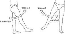
- the hip jointmovably connects the leg to the torso.
- the hip jointis a ball-and-socket joint, and is capable of a wide range of different motions, e.g., flexion and extension, abduction and adduction, internal (medial) and external (lateral) rotation, etc. These motions are illustrated in FIGS. 1A-1D .
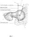
- the hip jointis formed at the junction of the femur and the hip. More particularly, and with reference to FIG. 2 , the ball of the femur is received in the acetabular cup of the hip, with a plurality of ligaments and other soft tissue serving to hold the bones in articulating condition.
- the hip jointis susceptible to a number of different pathologies (e.g., conditions or disorders). These pathologies can have both congenital and injury-related origins.
- One type of pathology of the hip jointinvolves impingement between the femoral head and/or femoral neck and the rim of the acetabular cup. This impingement is sometimes referred to as femoroacetabular impingement (FAI).
- FAI impingementcan occur due to irregularities in the geometry of the femur (e.g., due to an excess of bone on the femur). This type of impingement is sometimes referred to as cam-type FAI.
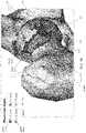
- cam-type FAIIn other cases, and with reference to FIG.
- the FAI impingementcan occur due to irregularities in the geometry of the acetabular cup (e.g., due to an excess of bone on the acetabular cup).
- This latter type of impingementis sometimes referred to as pincer-type FAI.
- the impingementmay be due to irregularities in the geometry of both the femur and the acetabulum (e.g., an excess of bone on both the femur and the acetabular cup).
- This type of impingementis sometimes referred to as mixed-type FAI.
- the salient feature of the impingementis that the bone of the femur and acetabulum approach and impinge on one another and any intermediary soft tissues during “normal” articulation of the hip joint.
- the FAIcan result in a reduced range of motion, substantial pain and, in some cases, significant deterioration of the hip joint.
- the FAImay be sufficiently severe as to require surgical intervention, e.g., removal of the bone causing the FAI and repair of any damaged soft tissues.
- a current trend in orthopedic surgeryis to treat joint pathologies using minimally-invasive arthroscopic techniques, for example, “keyhole” surgery conducted through small portals in the skin, with the surgical site being visualized with arthroscopes.
- minimally-invasive arthroscopic techniquesfor example, “keyhole” surgery conducted through small portals in the skin, with the surgical site being visualized with arthroscopes.
- physicianstend to err on the side of caution and remove less bone rather than more bone.
- under-resection of the pathologyis the leading cause of revision hip arthroscopy.
- two common anatomical measurements used in assessing FAIare: (i) the Alpha Angle for cam-type impingement, and (ii) the Lateral Center Edge Angle for pincer-type impingement. These two measurements are typically obtained by analyzing pre-operative images (e.g., pre-operative X-ray images), with the two measurements providing a measure of the degree to which the patient's hip anatomy deviates from normal, healthy hip anatomy.
- pre-operative imagese.g., pre-operative X-ray images
- the surgeonmanually draws a best-fit circle 5 over the femoral head 10 so that the perimeter of the circle matches the perimeter of the femoral head as closely as possible.
- the surgeonthen manually draws a line 15 along the mid-line of the femoral neck 20 .
- the surgeonthen manually draws a second line 25 which originates at the center of the femoral head and passes through the location which signifies the start of the cam pathology 30 (i.e., the location where the bone first extends outside the circle 5 set around the femoral head 10 ).
- the surgeonmeasures the angle 35 between the two lines 15 , 25 : this angle is the patient's Alpha Angle 35 .
- An Alpha Angle of greater than 42 degreesis typically indicative of a cam deformity
- an Alpha Angle of greater than 55 degreesis typically indicative of a clinically-significant impingement leading to a decreased range of motion compared to a normal hip.
- the surgeonmanually draws a vertical line 40 which originates at the center of the femoral head 10 and is perpendicular to the horizontal axis and then manually draws a second line 45 which originates at the center of the femoral head and passes through the location which signifies the start of the pincer pathology 50 (i.e., the rim of the acetabular cup).
- the surgeonmeasures the angle 55 between the two lines 40 , 45 : this angle is the patient's Lateral Center Edge Angle.
- a Lateral Center Edge Angle of between 20-25 degreesis typically indicative of borderline undercoverage and may result in hip instability
- a Lateral Center Edge Angle of less than 20 degreesis typically indicative of hip dysplasia
- a Lateral Center Edge Angle of greater than 40 degreesis typically indicative of overcoverage (pincer-type FAI) and may result in hip impingement and a decreased range of motion.
- Acetabular Versionis measured as the angle 60 ( FIG. 7 ) between the sagittal plane 65 (perpendicular to the frontal plane, not shown, and perpendicular to the horizontal axis 70 ) and a line 75 that connects the posterior and anterior aspects of the acetabular rim on a transverse plane.
- Acetabular version of 15-20 degreesis generally considered normal, while acetabular anteversion greater than 25 degrees is considered indicative of anterior undercoverage and may result in hip instability.
- Acetabular retroversioni.e.: acetabular version less than 15 degrees
- Femoral Torsionis measured as the projected (axial) angle 80 ( FIG. 8 ) between the femoral neck axis 85 and the condylar axis 90 and incorporates both neck inclination and femoral shaft rotation.
- Femoral torsion of 10-20 degreesis considered normal, while femoral torsion of greater than 25 degrees is considered pathologic and may result in hip instability.
- Femoral torsion of less than 5 degreesis considered pathologic and may result in hip impingement.
- pre-operative joint visualization systems and methodsare provided for assisting a physician in planning for a surgical procedure to address a joint pathology (e.g., a joint condition or disorder).
- visualizationscan provide guidance with respect to the extent of the pathology and how much bone should be removed during a surgical procedure using, for example, minimally-invasive arthroscopic techniques or open surgical procedures.
- patient-specific and/or patient population informationis obtained, preferably via a 3D imaging process.
- a patient's hip jointe.g., the femoral head, the femoral neck and the acetabular cup
- pelvise.g., the femoral condyles
- femoral condylesmay be scanned with an imaging apparatus (e.g., a CT scanner, an MRI scanner, etc.) and the imaging data may used to build a virtual 3D model of the patient's hip joint.
- an imaging apparatuse.g., a CT scanner, an MRI scanner, etc.
- the virtual 3D modelmay then be analyzed to generate a set of patient-specific measurements that are associated with a planned surgery (e.g., Alpha Angle calculations for cam-type FAI procedures, Lateral Center Edge Angle calculations for pincer-type FAI procedures, measurements of Acetabular Version and Femoral Torsion, etc.).
- a planned surgerye.g., Alpha Angle calculations for cam-type FAI procedures, Lateral Center Edge Angle calculations for pincer-type FAI procedures, measurements of Acetabular Version and Femoral Torsion, etc.
- the virtual 3D modelmay be analyzed with reference to a baseline anatomy derived, for example, from data from a patient population.
- patient-specific measurementsmay be integrated into a virtual 3D rendering of the 3D model.
- additional virtual objects that are representative of the patient-specific measurementsmay be integrated into the virtual 3D rendering. Images may be generated that graphically illustrate important measurement and morphology features relating to an FAI lesion and proper resection of the FAI lesion.
- a physiciancan be provided with information (including measurements and visualizations) on the extent of a pathology, and how much bone should be removed, in order to restore normal morphology, and information (including measurements and visualizations) about the bone, such as for treating FAI using minimally-invasive arthroscopic techniques or an open surgical procedure.
- a method for visualizing at least one region of a joint that deviates from a baseline anatomy for a surgical procedure on the at least one region of the jointincludes receiving image data associated with a joint of a subject, generating a three-dimensional model of at least a portion of the joint of the subject using the image data, identifying at least one region of the joint that deviates from the baseline anatomy by comparing at least a portion of the three-dimensional model to a baseline model, generating a measurement of a characteristic of the joint at one or more predefined locations using the three-dimensional model and a coordinate system, and generating a three-dimensional rendering of the model, wherein the three-dimensional rendering comprises: a visual indication of the at least one region of the three-dimensional model that deviates from the baseline, wherein the at least one region is visually indicated according to degree of deviation, and a representation of the measurement of the characteristic of the joint that is positioned in the rendering according to the one or more predefined locations.
- the image datacan include at least one of an MRI scan and a CT scan.
- the three-dimensional renderingcan include a visual indication of the coordinate system.
- the coordinate systemcan include clock-face lines.
- the representation of the measurementcan be provided adjacent to a clock-face line.
- the visual indication of the at least one regioncan be a heat map.
- the heat mapcan indicate an amount of tissue to remove to match the baseline anatomy.
- the jointcan be a hip joint and the measurement of the characteristic can include at least one of an alpha angle and a lateral center edge angle.
- the jointcan be a hip joint and the deviation from the baseline can be associated with at least one of a cam-type impingement and a pincer-type impingement.
- the three-dimensional renderingcan include at least one indication of a location of a threshold characteristic value in the rendering.
- the at least one indicationcan include a curve connecting points that meet the threshold characteristic value.
- the jointcan be a hip joint
- the characteristiccan be an alpha angle
- the threshold characteristic valuecan be 55 degrees, 65 degrees, or 75 degrees.
- the methodmay further include displaying a spectrum bar graph that comprises the representation of the measurement of the characteristic of the joint, wherein regions of the spectrum bar graph are visually-coded to indicate normal and abnormal anatomical measurement ranges.
- the methodmay further include displaying a coordinate system value that is associated with the representation of the measurement.
- the methodmay further include displaying a representation of at least a portion of a resection tool and visually coding the representation to indicate a dimension of the at least a portion of the resection tool, wherein the visual coding is coordinated with the visual indication of the at least one region of the three-dimensional model that deviates from the baseline.
- a system for generating a visualization of at least one region of a joint that deviates from a baseline anatomy for a surgical procedure on the at least one region of the jointcomprising one or more processors, memory, and one or more programs, wherein the one or more programs are stored in the memory and configured to be executed by the one or more processors, the one or more programs including instructions for: receiving image data associated with a joint of a subject; generating a three-dimensional model of at least a portion of the joint of the subject using the image data; identifying at least one region of the joint that deviates from the baseline anatomy by comparing at least a portion of the three-dimensional model to a baseline model; generating a measurement of a characteristic of the joint at one or more predefined locations using the three-dimensional model and a coordinate system; and generating a three-dimensional rendering of the model, wherein the three-dimensional rendering comprises: a visual indication of the at least one region of the three-dimensional model that deviates from the baseline, wherein the
- the systemcan be configured to receive the image data from an imaging system via a communication network.
- the systemcan be configured for transmitting the three-dimensional rendering to a clinical system via a communication network for display to a surgeon for preparing for the surgical procedure on the at least one region of the joint.
- the image datacan include at least one of an MRI scan and a CT scan.
- the three-dimensional renderingcan include a visual indication of the coordinate system.
- the coordinate systemcan include clock-face lines.
- the representation of the measurementcan be provided adjacent to a clock-face line.
- the visual indication of the at least one regioncan include a heat map.
- the heat mapcan indicate an amount of tissue to remove to match the baseline anatomy.
- the jointcan be a hip joint and the measurement of the characteristic can include at least one of an alpha angle and a lateral center edge angle.
- the jointcan be a hip joint and the deviation from the baseline can be associated with at least one of a cam-type impingement and a pincer-type impingement.
- the three-dimensional renderingcan include at least one indication of a location of a threshold characteristic value in the rendering.
- the at least one indicationcan include a curve connecting points that meet the threshold characteristic value.
- the jointcan be a hip joint
- the characteristiccan be an alpha angle
- the threshold characteristic valuecan be 55 degrees, 65 degrees, or 75 degrees.
- the one or more programscan include instructions for displaying a spectrum bar graph that comprises the representation of the measurement of the characteristic of the joint, wherein regions of the spectrum bar graph are visually-coded to indicate normal and abnormal anatomical measurement ranges.
- the one or more programscan include instructions for displaying a coordinate system value that is associated with the representation of the measurement.
- the one or more programscan include instructions for displaying a representation of at least a portion of a resection tool and visually coding the representation to indicate a dimension of the at least a portion of the resection tool, wherein the visual coding is coordinated with the visual indication of the at least one region of the three-dimensional model that deviates from the baseline.
- a non-transitory computer readable storage mediumstores one or more programs, the one or more programs comprising instructions for execution by one or more processors for receiving image data associated with a joint of a subject; generating a three-dimensional model of at least a portion of the joint of the subject using the image data; identifying at least one region of the joint that deviates from a baseline anatomy by comparing at least a portion of the three-dimensional model to a baseline model; generating a measurement of a characteristic of the joint at one or more predefined locations using the three-dimensional model and a coordinate system; and generating a three-dimensional rendering of the model, wherein the three-dimensional rendering comprises: a visual indication of the at least one region of the three-dimensional model that deviates from the baseline, wherein the at least one region is visually indicated according to degree of deviation, and a representation of the measurement of the characteristic of the joint that is positioned in the rendering according to the one or more predefined locations.
- a method for visualizing at least one region of a joint that deviates from a baseline anatomy for a surgical procedure on the at least one region of the jointincludes receiving image data associated with a joint of a subject; generating a three-dimensional model of at least a portion of the joint of the subject using the image data; identifying at least one region of the joint that deviates from the baseline anatomy by comparing at least a portion of the three-dimensional model to a baseline model; generating a measurement of a characteristic of the joint at one or more predefined locations using the three-dimensional model and a coordinate system; and generating a three-dimensional rendering of the model, wherein the three-dimensional rendering comprises: a visual indication of the at least one region of the three-dimensional model that deviates from the baseline, wherein the at least one region is visually indicated according to degree of deviation, and a boundary line indicating a boundary within which the baseline anatomy lies.
- the boundary linecan indicate a boundary within which a defined percentage of a reference population lies.
- the three-dimensional rendering of the modelcan include two boundary lines indicating boundaries within which a defined percentage of a reference population lies.
- the image datacan include at least one of an MRI scan and a CT scan.
- the three-dimensional renderingcan include a visual indication of the coordinate system.
- the coordinate systemcan include clock-face lines.
- the visual indication of the at least one regioncan be a heat map.
- the heat mapcan indicate an amount of tissue to remove to match the baseline anatomy.
- the jointcan be a hip joint and the deviation from the baseline can be associated with at least one of a cam-type impingement and a pincer-type impingement.
- the three-dimensional renderingcan include at least one indication of a location of a threshold characteristic value in the rendering.
- the at least one indicationcan include a curve connecting points that meet the threshold characteristic value.
- the jointcan be a hip joint
- the characteristiccan be an alpha angle
- the threshold characteristic valuecan be 55 degrees, 65 degrees, or 75 degrees.
- the methodmay further include displaying a spectrum bar graph that comprises a representation of a measurement of a characteristic of the joint, wherein regions of the spectrum bar graph are visually-coded to indicate normal and abnormal anatomical measurement ranges.
- the methodmay further include displaying a coordinate system value that is associated with the representation of the measurement.
- the methodmay further include displaying a representation of at least a portion of a resection tool and visually coding the representation to indicate a dimension of the at least a portion of the resection tool, wherein the visual coding is coordinated with the visual indication of the at least one region of the three-dimensional model that deviates from the baseline.
- a system for generating a visualization of at least one region of a joint that deviates from a baseline anatomy for a surgical procedure on the at least one region of the jointcomprising one or more processors, memory, and one or more programs, wherein the one or more programs are stored in the memory and configured to be executed by the one or more processors, the one or more programs including instructions for: receiving image data associated with a joint of a subject; generating a three-dimensional model of at least a portion of the joint of the subject using the image data; identifying at least one region of the joint that deviates from the baseline anatomy by comparing at least a portion of the three-dimensional model to a baseline model; generating a measurement of a characteristic of the joint at one or more predefined locations using the three-dimensional model and a coordinate system; and generating a three-dimensional rendering of the model, wherein the three-dimensional rendering comprises: a visual indication of the at least one region of the three-dimensional model that deviates from the baseline, wherein the
- the boundary linecan indicate a boundary within which a defined percentage of a reference population lies.
- the three-dimensional rendering of the modelcan include two boundary lines indicating boundaries within which a defined percentage of a reference population lies.
- the systemcan be configured to receive the image data from an imaging system via a communication network.
- the systemcan be configured for transmitting the three-dimensional rendering to a clinical system via a communication network for display to a surgeon for preparing for the surgical procedure on the at least one region of the joint.
- the image datacan include at least one of an MRI scan and a CT scan.
- the three-dimensional renderingcan include a visual indication of the coordinate system.
- the coordinate systemcan include clock-face lines.
- the visual indication of the at least one regioncan include a heat map.
- the heat mapcan indicate an amount of tissue to remove to match the baseline anatomy.
- the jointcan be a hip joint and the deviation from the baseline can be associated with at least one of a cam-type impingement and a pincer-type impingement.
- the three-dimensional renderingcan include at least one indication of a location of a threshold characteristic value in the rendering.
- the at least one indicationcan include a curve connecting points that meet the threshold characteristic value.
- the jointcan be a hip joint
- the characteristiccan be an alpha angle
- the threshold characteristic valuecan be 55 degrees, 65 degrees, or 75 degrees.
- the one or more programscan include instructions for displaying a spectrum bar graph that comprises a representation of a measurement of a characteristic of the joint, wherein regions of the spectrum bar graph are visually-coded to indicate normal and abnormal anatomical measurement ranges.
- the one or more programscan include instructions for displaying a coordinate system value that is associated with the representation of the measurement.
- the one or more programscan include instructions for displaying a representation of at least a portion of a resection tool and visually coding the representation to indicate a dimension of the at least a portion of the resection tool, wherein the visual coding is coordinated with the visual indication of the at least one region of the three-dimensional model that deviates from the baseline.
- a non-transitory computer readable storage mediumstores one or more programs, the one or more programs comprising instructions for execution by one or more processors for: receiving image data associated with a joint of a subject; generating a three-dimensional model of at least a portion of the joint of the subject using the image data; identifying at least one region of the joint that deviates from a baseline anatomy by comparing at least a portion of the three-dimensional model to a baseline model; generating a measurement of a characteristic of the joint at one or more predefined locations using the three-dimensional model and a coordinate system; and generating a three-dimensional rendering of the model, wherein the three-dimensional rendering comprises: a visual indication of the at least one region of the three-dimensional model that deviates from the baseline, wherein the at least one region is visually indicated according to degree of deviation, and a boundary line indicating a boundary within which the baseline anatomy lies.
- FIGS. 1A-1Dare schematic views showing the range of motion of, for example, a hip joint
- FIG. 2is a schematic view showing the bony anatomy in the region of the hip joint
- FIG. 3is a schematic view showing cam-type FAI
- FIG. 4is a schematic view showing pincer-type FAI
- FIG. 5is a schematic view showing how an Alpha Angle measurement is computed
- FIG. 6is a schematic view showing how a Lateral Center Edge Angle measurement is computed
- FIG. 7is a schematic view showing how an Acetabular Version measurement is computed
- FIG. 8is a schematic view showing how a Femoral Torsion measurement is computed
- FIGS. 9 a - dillustrate various pre-operative planning visualizations, according to some embodiments.
- FIGS. 10 and 11illustrate exemplary 3D renderings having clock-face line(s) and visually-coded pathology regions and pathology measurement information, according to some embodiments
- FIGS. 12-14are schematic views illustrating spectrum bar graphs, according to some embodiments.
- FIG. 15is a schematic view illustrating a 3D rendering having acetabular rim ranges, according to some embodiments.
- FIG. 16is a schematic view illustrating a resection tool representation having color coding in combination with a 3D model and visually-coded pathology surfaces.
- FIG. 17illustrates a system for imaging a joint of a subject, generating 3D renderings of the joint, and displaying the 3D renderings to a practitioner, according to various embodiments.
- FIG. 18illustrates an example of a computing system for generating a visualization, according to various embodiments.
- systems and methods according to the principles described hereincan provide visualizations of at least one region of a joint that deviates from a baseline, which can assist a practitioner in planning for a surgical procedure on the at least one region of the joint.
- a visualization of a hip joint of a subjectcan be provided that indicates a location of a hip joint pathology (e.g., a condition or a disorder), such as an FAI, and an amount of bone that may be removed to match a baseline anatomy.
- a hip joint pathologye.g., a condition or a disorder
- Visualizationscan be generated from a three-dimensional model of the joint of a subject that is generated from one or more scans of the subject.
- Information regarding deviations from a baseline anatomycan be generated by comparing the three-dimensional model to baseline data.
- the baseline datacan represent target joint morphology.
- Target joint morphologycan be any joint morphology that may be desired for a given subject.
- Target joint morphologycan be based on the anatomy representative of any reference patient population, such as a normal patient population.
- baseline datacan be a model of a “normal” joint that is derived from studies of a healthy patient population and/or from a model generated based on measurements, computer simulations, calculations, etc.
- target, baseline, and referenceare used interchangeably herein to describe joint morphology characteristics against which a subject's joint morphology is compared.
- the three-dimensional model and the information regarding deviations from a baseline/target anatomycan be used to generate a three-dimensional rendering of the joint that shows the deviations from the baseline/target anatomy. Visualizations can be created that include the three-dimensional rendering and/or other information related to the subject joint.
- hip jointsAlthough the following examples often refer to hip joints, hip joint pathologies, and hip joint characteristics and measurements, it is to be understood that systems, methods, techniques, visualizations, etc., for analyzing and visualizing other joints, including knee joints, shoulder joints, elbow joints, etc., are within the scope of the invention.
- a physiciancan be provided with improved guidance with respect to the extent of a deviation of a joint morphology from a target morphology, and how much bone should be removed to achieve the target morphology, for example, during a minimally-invasive arthroscopic procedure or open surgical procedure.
- visualizationscan provide a physician with improved guidance with respect to morphology measurements for a hip joint, including the Alpha Angle, Lateral Center Edge Angle, Acetabular Version and Femoral Torsion, Tönnis angle, neck shaft angle, and acetabular coverage that can help a practitioner gauge a deviation of the subject morphology from a target morphology.
- FIGS. 9 a - dillustrate various pre-operative planning visualization features, according to some embodiments.
- any of the various features illustrated in FIGS. 9 a - dmay be generated individually and/or in combination with any of the other features illustrated in FIGS. 9 a - d .
- any of the information, visualizations, features, data, measurements, etc., illustrated in FIGS. 9 a - dmay be provided to a user in any form.
- one or more featuresmay be provided in one or more user interfaces of a web page, an “app” for a tablet or smartphone or computer, etc.
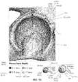
- “Clock-face lines” 2are artificial virtual objects inserted into the patient-specific virtual 3D model rendered from scan data. The use of clock-face lines are as described in the literature, and are useful for identifying positions within the hip joint.
- Resection depth (“pincer/cam depth”) 3is the distance between the patient's actual bone surface and the target bone surface, where the target bone surface is defined by the literature available on a particular measure of hip morphology (e.g., such as literature describing the results of a study of a large sample of patients having “normal” anatomy).
- the FAI lesion 4(in the case of the lesion identified by this visualization, a pincer-type FAI lesion) is color-coded according to resection depth.
- the cross-sectional view of a bur tool 5(used to resect the bone) is color-coded in order to relate it dimensionally to various resection depths.
- the cross-sectional view of a burwas chosen because it is the instrument which is typically used in arthroscopic surgery to remove bone pathologies.
- the use of a cross-sectional view of a burhelps to tie together the pre-operative planning to the intra-operative work by providing an approximate guide for the depth of bone recommended to be removed by the report relative to the dimensions of the tool.
- other shapes or sizes of surgical instrumentscould be used in place of the cross-sectional view of a bur.
- the reportcould be configured to show the resection depth on a smaller or larger bur, or on a cross-sectional view of a different bur, or a chisel or bone rasp depending on the physician's own preferences.
- the outer arcuate line 6 identified by this footnoteillustrates the position of an acetabular rim boundary within which 95% of a normal hip population will lie.
- a patient with a bone surface which lies outside (laterally) of this lineis considered to have pincer-type FAI for the purposes of the report.
- the inner arcuate line 7 identified by this footnoteillustrates the position of an acetabular rim boundary outside of which 95% of a normal hip population will lie.
- a patient with a bone surface which lies outside (medially) of this linemay be considered to have an unstable hip joint.
- Graphic 8illustrates the patient-specific measurement of the Acetabular Version at the “3 o'clock” position, shown (for example) with a marker labelled “28°”.
- the markeris based upon the specific measure of Acetabular Version made for the patient and is positioned along a spectrum labelled with representative Acetabular Version angles of 0°, 15°, 20° and 25°, and where the angle spectrum is color-coded to show population distributions (green is “normal”, red is “abnormal” and yellow is “marginal” or “borderline”), although other colors could be used for these representations of the anatomy, as could additional colors for more resolution in the different categories of pathologic variations.
- Table 9illustrates how a particular measure (i.e., the Later Center Edge Angle) changes with increasing degrees of resection depth (at the “12 o'clock” position), as if the virtual 3D model were modulated to reflect increasing degrees of bone resection.
- the specific changes in the Center Edge Angle with increasing degrees of bone resectionmay help the physician evaluate how much bone can/should be resected on the acetabular rim.
- Graphic 10is displayed if one of the measurements determined by the pre-operative planning tool is considered to be abnormal (e.g., in the red range) and representative of hip instability. If none of the measurements indicates instability, the graphic is not shown. This feature helps the physician decide if the acetabular resection should be conservative (i.e., if less bone should be removed) and in cases of severe hip instability whether additional treatment such as a peri-acetabular osteotomy may be appropriate.
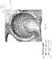
- Graphic 11illustrates patient-specific measurements of the Alpha Angle at specific clock-face positions; note that the patient-specific measurements of the Alpha Angle are superimposed on an image rendered from the virtual 3D model and are not artificial virtual objects inserted into the virtual 3D model.
- the FAI lesion 12(in the case of the lesion identified by this visualization, a cam-type FAI lesion) is color-coded according to the desired (i.e., target) resection depth, wherein the desired resection depth is the distance between the patient's actual bone surface and a target bone surface.
- the target bone surfacecan established by what is defined as normal anatomy, such as from studies published in the literature.
- the target bone surfacecan be generated primarily using the assumption that a femoral head is spherical and from Alpha Angle measurements.
- the “12 o'clock” and “9 o'clock” clock-face lines, and the “annular Alpha Angle of 55° line”may be artificial virtual objects inserted into a virtual 3D model. In other embodiments, this information is not inserted into the virtual 2D model, but instead are rendered on the 3D rendering generated from the virtual 3D model. In some embodiments, other information, such as the remaining clock-face and Alpha Angle lines are rendered on the 3D rendering generated from the virtual 3D model.
- the shaded region 14 in FIG. 9 brepresents the superior portion of the femoral head which is covered by the projected area of the acetabulum when the femur is in a neutral position with respect to the acetabulum (while the patient is standing or laying down).
- the quadrantsindicate the medial/lateral and posterior/anterior portions of the femoral head.
- the horizontal lines 15indicate the Acetabular Version at the “3 o'clock”, “2 o'clock” and “12 o'clock” positions of the acetabulum.
- the sagittal plane at the center of the femoral headis shown transparently for graphical reference and supports an inference of the orientation of the acetabular socket at the other clock-face positions.
- FIG. 9 cillustrates a rotatable 3D rendering that may be provided to enable a practitioner to rotate the 3D rendering on a display screen (e.g., using a user input device such as a touch screen, mouse, keyboard, voice control interface, etc.).
- a user input devicesuch as a touch screen, mouse, keyboard, voice control interface, etc.
- the center 16 of the femoral headis represented by a spherical virtual object which is inserted into the virtual 3D rendering.
- the center of the femoral neck 17is represented by a virtual rod which is inserted into the virtual 3D rendering.
- the virtual 3D renderingmay be rotatable.
- FIGS. 10 and 11illustrate visualizations that include a unique combination of elements not previously provided in a single image. More particularly, these displays provide information about a pathology (e.g., a lesion, a bony deformity, or another condition) of a hip joint by providing a three-dimensional rendering 100 of at least a portion of a hip joint which contains: (i) a region 105 associated with a pathology, with the region 105 being visually-coded 110 on the three-dimensional rendering 100 so as to indicate the height (or thickness or depth or dimension) of the region 105 relative to a target anatomy; (ii) clock-face lines 115 ; and (iii) a representation of the measurement 120 of a characteristic of the joint that is positioned at clock-face positions.
- the measurementmay relate to an extent of a pathology.
- Clock-face lines 115are of the sort which are well known in the art, and which are widely used for identifying positions within the hip joint (e.g., for identifying rotational positions about the femoral head, the acetabular cup, etc.).
- the measurement 120 for a particular clock-face positionis positioned adjacent to the region 105 and adjacent to the clock-face line 115 pertaining to the measurement.
- the pathologymay be a cam lesion, and the measurement may comprise an Alpha Angle measurement.
- the three-dimensional rendering 100 of the at least a portion of the hip jointmay be include at least one Alpha Angle arc 125 set at a pre-determined Alpha Angle position.
- the pre-determined Alpha Angle measurementmay be selected from the group consisting of approximately 35, 45, 55, 65, 75, 85, and 95 degrees.
- the pre-determined Alpha Angle measurementmay be selected from the group consisting of 5 degree and/or 10 degree increments.
- the pre-determined Alpha Angle measurementmay be selected from the group consisting of both 5 degree and/or 10 degree increments and a group consisting of approximately 42 degrees and approximately 55 degrees.
- the pathologymay be a pincer lesion, and the measurement may comprise a Center Edge Angle measurement.
- the region 105is color-coded to indicate the height of the pathology relative to a target anatomy (e.g., non-pathologic, or desired, anatomy, which may be derived from measurements on subjects with normal bone morphology).
- a target anatomye.g., non-pathologic, or desired, anatomy, which may be derived from measurements on subjects with normal bone morphology.
- the visual coding provided on the surface of the pathologymay use non-color-coding, e.g., the visual coding may use varying shading, varying fill patterns, varying fill densities, etc.
- FIGS. 12-14( FIG. 12 relating to Alpha Angle measurements, FIG. 13 relating to Acetabular Version measurements, and FIG. 14 relating to Femoral Torsion measurements) comprise a unique combination of elements not previously provided in a single image. More particularly, these displays provide information about an anatomical characteristic of a hip joint, by combining: (i) a spectrum bar graph 130 , wherein anatomical measurement indicia 135 are disposed along the length of the spectrum bar graph 130 , and further wherein regions of the spectrum bar graph 130 are visually-coded at 140 to indicate normal, abnormal and marginal (borderline) anatomical measurement ranges on the spectrum bar graph 130 ; and (ii) annotating the spectrum bar graph 130 with at least one anatomical measurement 145 associated with the hip joint, or an index combining several measures into one.
- anatomical measurement indicia 135may be disposed at regular intervals (e.g., 5 degree intervals) along spectrum bar graph 130 , or the anatomical measurement indicia 135 may be at the border between two of the normal, abnormal and marginal (borderline) measurement ranges.
- regions of the spectrum bar graph 130are visually-coded to indicate normal, abnormal and marginal (borderline) anatomical measurement ranges on the spectrum bar graph 130 .
- the anatomical characteristicmay be a cam lesion, and the anatomical measurement information may comprise an Alpha Angle measurement.
- the spectrum bar graphmay be annotated with clock-face indicia 150 relating to the location at which the anatomical measurement was determined.
- the anatomical characteristicmay be a pincer lesion, and the anatomical measurement information may comprise a Center Edge Angle measurement.
- the anatomical characteristicmay be Acetabular Version ( FIG. 13 ) or Femoral Torsion ( FIG. 14 ), and the anatomical measurement information may be a retroversion/anteversion angle measurement.
- the regions of the spectrum bar graph 130are color-coded to indicate normal, abnormal and marginal (borderline) anatomical measurement ranges on the spectrum bar graph 130 .
- the visual coding provided on the regions of the spectrum bar graph 130may use non-color-coding, e.g., the visual coding may use varying shading, varying fill patterns, varying fill densities, etc.
- the visualization shown in FIG. 15comprises a unique combination of elements not previously provided in a single image. More particularly, this display provides information about the acetabular rim of a hip joint, by providing a 3D rendering 155 of at least a portion of the acetabular rim of a hip joint that includes: (i) a region 156 associated with a pathology, with the region 156 being visually-coded 157 on the three-dimensional rendering 155 so as to indicate the height (or thickness or depth or dimension) of the region 156 relative to a target anatomy; and (ii) an arcing boundary line 160 indicating an acetabular boundary within which the anatomy of at least 95% of a normal population lies.
- clock-face linesmay also be incorporated in the display.
- the arcing boundary line 160indicates an acetabular boundary within which the anatomy of at least 95% of a normal population lies.
- the three-dimensional rendering 155 of at least a portion of the acetabular rim of the hip jointmay be annotated with at least two arcing boundary lines 160 indicating acetabular boundaries within which the anatomy of at least 95% of a reference population lies.
- the three-dimensional rendering 155is generated by rendering an image of a user-rotatable three-dimensional model of at least a portion of the acetabular rim of a hip joint, and the arcing boundary line 160 is locked in position relative to the three-dimensional model of at least a portion of the acetabular rim of a hip joint. This may be achieved by forming the arcing boundary line 160 as a virtual object inserted into the three-dimensional model of at least a portion of the acetabular rim of a hip joint.
- a visualizationis provided that includes a unique combination of elements not previously provided in a single image. More particularly, this visualization provides information about resecting a bony deformity of a hip joint, by providing a three-dimensional rendering 165 of at least a portion of a hip joint which contains the bony deformity, with the region 170 of the bony deformity being visually-coded at 175 on the three-dimensional rendering 165 so as to indicate a dimension of the bony deformity taken relative to a target anatomy.
- the visualizationmay include a representation 180 of at least a portion of a tool for performing a resection of the bony deformity, wherein at least a portion of the tool is visually-coded at 185 so as to indicate a dimension of at least a portion of the tool, and further wherein the visual-coding at 185 of the dimension of at least a portion of the tool is coordinated with the visual-coding at 175 of the region 170 of the bony deformity taken relative to a target anatomy.
- Such coordination between the surgical tool and the images in the reportprovides the surgeon with a visual reference for dimensions, such as the depth of resection.
- the region of the bony deformityis color-coded to indicate a dimension of the bony deformity taken relative to a desired anatomy
- the representation of the at least a portion of the toolis color-coded to indicate a dimension of the at least a portion of the tool.
- the visual coding provided on the surface of the bony deformity and the visual coding provided on the toolmay use non-color-coding, e.g., the visual coding may use varying shading, varying fill patterns, varying fill densities, etc.
- the representation of at least a portion of the toolcomprises a side view of the at least a portion of the tool, which may include at least the distal end of the tool.
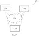
- FIG. 17illustrates a system 1700 for imaging a joint of a subject, generating 3D renderings of the joint, and displaying the 3D renderings to a practitioner, according to various embodiments.
- System 1700includes an imaging subsystem 1702 for imaging the joint of the subject, a visualization generating subsystem 1704 for generating visualizations of the joint from imaging generated by the imaging subsystem, and a display subsystem 1706 for displaying generated visualizations to a practitioner.
- the subsystemsmay be communicatively connected via a network 1708 , such as a local area network, a wide area network, a combination of local and wide area networks, or any suitable communication network.
- the subsystemsmay be directly connected to one another such that data is transferred from one subsystem to another directly, without being routed through a network.
- an imaging subsystem and a visualization generating subsystemmay be different portions of the same operating suite.
- Imaging subsystem 1702can include an imager for generating imaging data for a subject. Imaging data can include, for example, MRI scans, CT scans, x-rays, fluorescence imaging data, or any suitable imaging data for imaging a joint of a subject. In some embodiment, the imaging subsystem 1702 can include one or more imaging data processing systems for processing imaging data generated by an imager. The imaging subsystem 1702 can include one or more data storage systems for storing imaging data. The imaging subsystem 1702 can be configured to transmit imaging data for a joint of a subject to visualization generating subsystem 1704 .
- imaging data generated during the sessioncan be transmitted to the visualization generating subsystem 1704 for generating visualizations, according to the principles described above.
- datais transferred from an imaging subsystem to a visualization generating subsystem 1704 in the same facility, such as a central computing system.
- datais transferred to a remote system, such as one operated by a third party that provides a visualization generation service.
- the visualization generating subsystem 1704can be configured to receive imaging data and use some or all of the imaging data for generating a three-dimensional model of at least a portion of the joint of the subject.
- the subsystem 1704can identify at least one region of the joint that deviates from a baseline anatomy by comparing at least a portion of the three-dimensional model to a baseline model.
- the subsystem 1704can generate a measurement of a characteristic of the joint at one or more predefined locations using the three-dimensional model and a coordinate system; and can generate a three-dimensional rendering of the model, according to the principles described herein.
- the three-dimensional renderingcan include a visual indication of the at least one region of the three-dimensional model that deviates from the baseline, wherein the at least one region is visually indicated according to degree of deviation.
- the three-dimensional renderingcan be a component of a visualization that includes any other relevant information as described herein.
- the visualization generating subsystem 1704can be configured to transmit visualizations, such as those including three-dimensional renderings, to display subsystem 1706 for displaying the generated visualizations to a practitioner to help the practitioner plan a surgical procedure to correct a pathology analyzed and indicated in the visualization.
- the visualizationscan be displayed to a computer used by a practitioner via, for example, a web interface or an app.
- the display subsystemcan include one or more operating room displays for displaying the visualizations to the practitioner during surgery.
- FIG. 18illustrates an example of a computing system, in accordance with some embodiments, for generating visualization according to the principles described herein.
- System 1800can be used for one or more of subsystems 1702 , 1704 , and 1706 of system 1700 .
- System 1800can be a computer connected to a network, such as network 1708 of system 1700 .
- System 1800can be a client computer or a server.
- system 1800can be any suitable type of microprocessor-based system, such as a personal computer, workstation, server, or handheld computing device (portable electronic device) such as a phone or tablet.
- the systemcan include, for example, one or more of processor 1810 , input device 1820 , output device 1830 , storage 1840 , and communication device 1860 .
- Input device 1820 and output device 1830can generally correspond to those described above and can either be connectable or integrated with the computer.
- Input device 1820can be any suitable device that provides input, such as a touch screen, keyboard or keypad, mouse, or voice-recognition device.
- Output device 1830can be any suitable device that provides output, such as a touch screen, haptics device, or speaker.
- Storage 1840can be any suitable device that provides storage, such as an electrical, magnetic, or optical memory including a RAM, cache, hard drive, or removable storage disk.
- Communication device 1860can include any suitable device capable of transmitting and receiving signals over a network, such as a network interface chip or device.
- the components of the computercan be connected in any suitable manner, such as via a physical bus or wirelessly.
- Software 1850which can be stored in storage 1840 and executed by processor 1810 , can include, for example, the programming that embodies the functionality of the present disclosure (e.g., as embodied in the devices as described above).
- Software 1850can also be stored and/or transported within any non-transitory computer-readable storage medium for use by or in connection with an instruction execution system, apparatus, or device, such as those described above, that can fetch instructions associated with the software from the instruction execution system, apparatus, or device and execute the instructions.
- a computer-readable storage mediumcan be any medium, such as storage 1840 , that can contain or store programming for use by or in connection with an instruction execution system, apparatus, or device.
- Software 1850can also be propagated within any transport medium for use by or in connection with an instruction execution system, apparatus, or device, such as those described above, that can fetch instructions associated with the software from the instruction execution system, apparatus, or device and execute the instructions.
- a transport mediumcan be any medium that can communicate, propagate or transport programming for use by or in connection with an instruction execution system, apparatus, or device.
- the transport readable mediumcan include, but is not limited to, an electronic, magnetic, optical, electromagnetic, or infrared wired or wireless propagation medium.
- System 1800may be connected to a network, which can be any suitable type of interconnected communication system.
- the networkcan implement any suitable communications protocol and can be secured by any suitable security protocol.
- the networkcan comprise network links of any suitable arrangement that can implement the transmission and reception of network signals, such as wireless network connections, T1 or T3 lines, cable networks, DSL, or telephone lines.
- System 1800can implement any operating system suitable for operating on the network.
- Software 1850can be written in any suitable programming language, such as C, C++, Java, or Python.
- application software embodying the functionality of the present disclosurecan be deployed in different configurations, such as in a client/server arrangement or through a Web browser as a Web-based application or Web service, for example.
- Certain aspects of the present disclosureinclude process steps and instructions described herein in the form of an algorithm. It should be noted that the process steps and instructions of the present disclosure could be embodied in software, firmware, or hardware and, when embodied in software, could be downloaded to reside on and be operated from different platforms used by a variety of operating systems. Unless specifically stated otherwise as apparent from the following discussion, it is appreciated that, throughout the description, discussions utilizing terms such as “processing,” “computing,” “calculating,” “determining,” “displaying,” “generating” or the like, refer to the action and processes of a computer system, or similar electronic computing device, that manipulates and transforms data represented as physical (electronic) quantities within the computer system memories or registers or other such information storage, transmission, or display devices.
- the present disclosurein some embodiments also relates to a device for performing the operations herein.
- This devicemay be specially constructed for the required purposes, or it may comprise a general purpose computer selectively activated or reconfigured by a computer program stored in the computer.
- a computer programmay be stored in a non-transitory, computer readable storage medium, such as, but not limited to, any type of disk, including floppy disks, USB flash drives, external hard drives, optical disks, CD-ROMs, magnetic-optical disks, read-only memories (ROMs), random access memories (RAMs), EPROMs, EEPROMs, magnetic or optical cards, application specific integrated circuits (ASICs), or any type of media suitable for storing electronic instructions, and each coupled to a computer system bus.
- the computers referred to in the specificationmay include a single processor or may be architectures employing multiple processor designs for increased computing capability.
Landscapes
- Health & Medical Sciences (AREA)
- Engineering & Computer Science (AREA)
- Life Sciences & Earth Sciences (AREA)
- Surgery (AREA)
- Physics & Mathematics (AREA)
- Veterinary Medicine (AREA)
- Public Health (AREA)
- General Health & Medical Sciences (AREA)
- Animal Behavior & Ethology (AREA)
- Heart & Thoracic Surgery (AREA)
- Biomedical Technology (AREA)
- Geometry (AREA)
- Theoretical Computer Science (AREA)
- Robotics (AREA)
- Nuclear Medicine, Radiotherapy & Molecular Imaging (AREA)
- Medical Informatics (AREA)
- Molecular Biology (AREA)
- Transplantation (AREA)
- Manufacturing & Machinery (AREA)
- Orthopedic Medicine & Surgery (AREA)
- Cardiology (AREA)
- Oral & Maxillofacial Surgery (AREA)
- Vascular Medicine (AREA)
- General Engineering & Computer Science (AREA)
- Evolutionary Computation (AREA)
- Computer Hardware Design (AREA)
- General Physics & Mathematics (AREA)
- Apparatus For Radiation Diagnosis (AREA)
- Architecture (AREA)
- Software Systems (AREA)
Abstract
Description
Claims (23)
Priority Applications (3)
| Application Number | Priority Date | Filing Date | Title |
|---|---|---|---|
| US16/261,464US11464569B2 (en) | 2018-01-29 | 2019-01-29 | Systems and methods for pre-operative visualization of a joint |
| US18/045,449US11957418B2 (en) | 2018-01-29 | 2022-10-10 | Systems and methods for pre-operative visualization of a joint |
| US18/636,181US20240261031A1 (en) | 2018-01-29 | 2024-04-15 | Systems and methods for pre-operative visualization of a joint |
Applications Claiming Priority (2)
| Application Number | Priority Date | Filing Date | Title |
|---|---|---|---|
| US201862623068P | 2018-01-29 | 2018-01-29 | |
| US16/261,464US11464569B2 (en) | 2018-01-29 | 2019-01-29 | Systems and methods for pre-operative visualization of a joint |
Related Child Applications (1)
| Application Number | Title | Priority Date | Filing Date |
|---|---|---|---|
| US18/045,449ContinuationUS11957418B2 (en) | 2018-01-29 | 2022-10-10 | Systems and methods for pre-operative visualization of a joint |
Publications (2)
| Publication Number | Publication Date |
|---|---|
| US20190231434A1 US20190231434A1 (en) | 2019-08-01 |
| US11464569B2true US11464569B2 (en) | 2022-10-11 |
Family
ID=67391699
Family Applications (3)
| Application Number | Title | Priority Date | Filing Date |
|---|---|---|---|
| US16/261,464Active2039-05-16US11464569B2 (en) | 2018-01-29 | 2019-01-29 | Systems and methods for pre-operative visualization of a joint |
| US18/045,449ActiveUS11957418B2 (en) | 2018-01-29 | 2022-10-10 | Systems and methods for pre-operative visualization of a joint |
| US18/636,181PendingUS20240261031A1 (en) | 2018-01-29 | 2024-04-15 | Systems and methods for pre-operative visualization of a joint |
Family Applications After (2)
| Application Number | Title | Priority Date | Filing Date |
|---|---|---|---|
| US18/045,449ActiveUS11957418B2 (en) | 2018-01-29 | 2022-10-10 | Systems and methods for pre-operative visualization of a joint |
| US18/636,181PendingUS20240261031A1 (en) | 2018-01-29 | 2024-04-15 | Systems and methods for pre-operative visualization of a joint |
Country Status (1)
| Country | Link |
|---|---|
| US (3) | US11464569B2 (en) |
Cited By (2)
| Publication number | Priority date | Publication date | Assignee | Title |
|---|---|---|---|---|
| US12193751B2 (en) | 2021-09-14 | 2025-01-14 | Arthrex, Inc. | Preoperative surgical planning systems and methods for generating and utilizing anatomical makeup classifications |
| US12433677B2 (en) | 2021-09-14 | 2025-10-07 | Arthrex, Inc. | Surgical planning systems and methods with postoperative feedback loops |
Families Citing this family (7)
| Publication number | Priority date | Publication date | Assignee | Title |
|---|---|---|---|---|
| CN110177492A (en) | 2016-11-18 | 2019-08-27 | 斯特赖克公司 | Method and apparatus for treating joint hits the treatment that the clamp type femur acetabular bone in disease and hip joint hits disease including the cam type femur acetabular bone in hip joint |
| US11337760B2 (en)* | 2018-03-27 | 2022-05-24 | Virginia Commonwealth University | Automated hip analysis methods and devices |
| US11452566B2 (en)* | 2018-12-21 | 2022-09-27 | Intellijoint Surgical Inc. | Pre-operative planning for reorientation surgery: surface-model-free approach using simulated x-rays |
| EP4106656A1 (en)* | 2020-02-21 | 2022-12-28 | Stryker Corporation | Systems and methods for visually guiding bone removal during a surgical procedure on a joint |
| CN111671518B (en)* | 2020-04-29 | 2021-04-16 | 北京天智航医疗科技股份有限公司 | Processing and generating method and device for hip joint femoral head spherical center and computer equipment |
| US12256996B2 (en)* | 2020-12-15 | 2025-03-25 | Stryker Corporation | Systems and methods for generating a three-dimensional model of a joint from two-dimensional images |
| US11890058B2 (en)* | 2021-01-21 | 2024-02-06 | Arthrex, Inc. | Orthopaedic planning systems and methods of repair |
Citations (116)
| Publication number | Priority date | Publication date | Assignee | Title |
|---|---|---|---|---|
| US5862249A (en) | 1995-12-01 | 1999-01-19 | Eastman Kodak Company | Automated method and system for determination of positional orientation of digital radiographic images |
| US6161080A (en) | 1997-11-17 | 2000-12-12 | The Trustees Of Columbia University In The City Of New York | Three dimensional multibody modeling of anatomical joints |
| US6205411B1 (en) | 1997-02-21 | 2001-03-20 | Carnegie Mellon University | Computer-assisted surgery planner and intra-operative guidance system |
| DE10057023A1 (en) | 2000-11-17 | 2002-06-06 | Siemens Ag | Method and appliance for identifying correct alignment of fractured bones by superimposition of templates on images of those bones |
| US20030176783A1 (en) | 2000-07-06 | 2003-09-18 | Qingmao Hu | Method and device for impingement detection |
| US6697664B2 (en) | 1999-02-10 | 2004-02-24 | Ge Medical Systems Global Technology Company, Llc | Computer assisted targeting device for use in orthopaedic surgery |
| US20050096535A1 (en) | 2003-11-04 | 2005-05-05 | De La Barrera Jose Luis M. | System and method of registering image data to intra-operatively digitized landmarks |
| US20070016008A1 (en) | 2005-06-23 | 2007-01-18 | Ryan Schoenefeld | Selective gesturing input to a surgical navigation system |
| US7167738B2 (en) | 2000-08-01 | 2007-01-23 | Stryker Leibinger Gmbh & Co., Kg | Method for navigating in the interior of the body using three-dimensionally visualized structures |
| US20070129630A1 (en) | 2005-12-07 | 2007-06-07 | Shimko Daniel A | Imaging method, device and system |
| US7231076B2 (en) | 2004-06-30 | 2007-06-12 | Accuray, Inc. | ROI selection in image registration |
| US20070135706A1 (en) | 2005-12-13 | 2007-06-14 | Shimko Daniel A | Debridement method, device and kit |
| US20070249967A1 (en) | 2006-03-21 | 2007-10-25 | Perception Raisonnement Action En Medecine | Computer-aided osteoplasty surgery system |
| US20070260256A1 (en) | 2006-05-05 | 2007-11-08 | Beaule Paul E | Surgical instrument tray, hip resurfacing kit, and method of resurfacing a femoral head to preserve femoral head vascularity |
| US7327865B2 (en) | 2004-06-30 | 2008-02-05 | Accuray, Inc. | Fiducial-less tracking with non-rigid image registration |
| US20080039717A1 (en) | 2006-08-11 | 2008-02-14 | Robert Frigg | Simulated bone or tissue manipulation |
| US20080300478A1 (en) | 2007-05-30 | 2008-12-04 | General Electric Company | System and method for displaying real-time state of imaged anatomy during a surgical procedure |
| US20090000626A1 (en) | 2002-03-06 | 2009-01-01 | Mako Surgical Corp. | Haptic guidance system and method |
| US20090209851A1 (en) | 2008-01-09 | 2009-08-20 | Stryker Leibinger Gmbh & Co. Kg | Stereotactic computer assisted surgery method and system |
| CN101518447A (en) | 2009-03-02 | 2009-09-02 | 北京积水潭医院 | Precision improving method for spinal surgery computer navigation system |
| US7643862B2 (en) | 2005-09-15 | 2010-01-05 | Biomet Manufacturing Corporation | Virtual mouse for use in surgical navigation |
| US20100049493A1 (en) | 2008-08-20 | 2010-02-25 | Martin Haimerl | Planning assistance for correcting joint elements |
| US7689042B2 (en) | 2005-06-30 | 2010-03-30 | Siemens Aktiengesellschaft | Method for contour visualization of regions of interest in 2D fluoroscopy images |
| US7783008B2 (en) | 2007-03-30 | 2010-08-24 | General Electric Company | Digital radiograph patient positioning system and method |
| US20100284590A1 (en) | 2007-12-21 | 2010-11-11 | Siemens Medical Solutions Usa, Inc. | Systems and Methods for Robust Learning Based Annotation of Medical Radiographs |
| US20110190774A1 (en) | 2009-11-18 | 2011-08-04 | Julian Nikolchev | Methods and apparatus for performing an arthroscopic procedure using surgical navigation |
| EP1844726B1 (en) | 2003-01-30 | 2011-08-17 | Surgical Navigation Technologies, Inc. | A display and a navigation system for guiding a medical device to a target |
| US20110213374A1 (en) | 2003-11-25 | 2011-09-01 | Conformis, Inc. | Patient Selectable Joint Arthroplasty Devices and Surgical Tools |
| US20110213379A1 (en) | 2010-03-01 | 2011-09-01 | Stryker Trauma Gmbh | Computer assisted surgery system |
| US8014984B2 (en) | 2007-03-06 | 2011-09-06 | The Cleveland Clinic Foundation | Method and apparatus for preparing for a surgical procedure |
| CN102194047A (en) | 2010-03-01 | 2011-09-21 | 斯特赖克创伤治疗有限责任公司 | Computer assisted surgery system |
| US20110238431A1 (en) | 2010-03-23 | 2011-09-29 | Robert Cionni | Surgical Console Information Management |
| US20110270295A1 (en) | 2010-02-17 | 2011-11-03 | Reprise Technologies, Llc | System and method for image-guided arthroscopy |
| US8052623B2 (en) | 2007-06-15 | 2011-11-08 | Brainlab Ag | Computer-assisted joint analysis using surface projection |
| US20110301654A1 (en) | 2008-11-05 | 2011-12-08 | Imperial Innovations Ltd. | Hip resurfacing |
| WO2011158117A2 (en) | 2010-06-16 | 2011-12-22 | A2 Surgical | Method and system of automatic determination of geometric elements characterizing a bone deformation from 3d image |
| US8090166B2 (en) | 2006-09-21 | 2012-01-03 | Surgix Ltd. | Medical image analysis |
| US8152816B2 (en) | 2007-06-15 | 2012-04-10 | Brainlab Ag | Computer-assisted planning method for correcting changes in the shape of joint bones |
| US20120271147A1 (en) | 2011-04-22 | 2012-10-25 | New York University | Apparatus, method, and computer-accessible medium for b1-insensitive high resolution 2d t1 mapping in magnetic resonance imaging |
| WO2012149964A1 (en) | 2011-05-04 | 2012-11-08 | Stryker Trauma Gmbh | Systems and methods for automatic detection and testing of images for clinical relevance |
| US8328816B2 (en) | 2005-07-20 | 2012-12-11 | Wright Medical Technology, Inc. | Femoral gauge |
| US20130089253A1 (en) | 2010-06-16 | 2013-04-11 | A2 Surgical | Method for determining bone resection on a deformed bone surface from few parameters |
| US20130114866A1 (en) | 2011-11-08 | 2013-05-09 | Mako Surgical Corporation | Computer-Aided Planning with Dual Alpha Angles in Femoral Acetabular Impingement Surgery |
| EP2618313A1 (en) | 2012-01-19 | 2013-07-24 | Clinical Graphics B.V. | Process to generate a computeraccessible medium comprising information on the functioning of a joint |
| US20130191099A1 (en) | 2012-01-19 | 2013-07-25 | Peter Roelof Krekel | Process for generating a computer-accessible medium including information on the functioning of a joint |
| US20130211232A1 (en) | 2012-02-01 | 2013-08-15 | The Johns Hopkins University | Arthroscopic Surgical Planning and Execution with 3D Imaging |
| US20130211408A1 (en) | 2012-02-08 | 2013-08-15 | Jens Kather | Curved Arthroscopic Burr and Measurement Instrumentation |
| US20130211386A1 (en) | 2010-07-16 | 2013-08-15 | Stryker Trauma Gmbh | Surgical targeting system and method |
| US8594397B2 (en) | 2008-05-15 | 2013-11-26 | Brainlab Ag | Joint reconstruction planning using model data |
| US20130314440A1 (en) | 2012-05-23 | 2013-11-28 | Stryker Trauma Gmbh | Virtual 3d overlay as reduction aid for complex fractures |
| US20130315371A1 (en) | 2012-05-23 | 2013-11-28 | Stryker Trauma Gmbh | Bone density measurement |
| WO2013174402A1 (en) | 2012-05-23 | 2013-11-28 | Stryker Trauma Gmbh | Locking screw length measurement |
| WO2013174401A1 (en) | 2012-05-23 | 2013-11-28 | Stryker Trauma Gmbh | Entry portal navigation |
| US8611697B2 (en) | 2007-06-21 | 2013-12-17 | Surgix Ltd. | System for measuring the true dimensions and orientation of objects in a two dimensional image |
| US8679125B2 (en) | 2010-09-22 | 2014-03-25 | Biomet Manufacturing, Llc | Robotic guided femoral head reshaping |
| US8678125B2 (en) | 2004-07-26 | 2014-03-25 | Yamaha Hatsudoki Kabushiki Kaisha | Speed change controller for saddle-ride type vehicles |
| WO2014048447A1 (en) | 2012-09-27 | 2014-04-03 | Stryker Trauma Gmbh | Rotational position determination |
| US8694075B2 (en) | 2009-12-21 | 2014-04-08 | General Electric Company | Intra-operative registration for navigated surgical procedures |
| US8696603B2 (en) | 2008-12-04 | 2014-04-15 | Fujifilm Corporation | System for measuring space width of joint, method for measuring space width of joint and recording medium |
| US8702805B2 (en) | 2008-07-21 | 2014-04-22 | Harutaro Trabish | Acetabulum surgical resurfacing aid |
| US8715289B2 (en) | 2011-04-15 | 2014-05-06 | Biomet Manufacturing, Llc | Patient-specific numerically controlled instrument |
| US20140187908A1 (en) | 2012-11-24 | 2014-07-03 | Jutta Ellermann | System and Method for Patient-Specific Planar Visualization of Volumetric MRI Data |
| US8828009B2 (en) | 2010-08-26 | 2014-09-09 | Smith & Nephew, Inc. | Implants, surgical methods, and instrumentation for use in femoroacetabular impingement surgeries |
| US8831324B2 (en) | 2012-10-02 | 2014-09-09 | Brad L. Penenberg | Surgical method and workflow |
| US20140278322A1 (en) | 2013-03-13 | 2014-09-18 | Branislav Jaramaz | Systems and methods for using generic anatomy models in surgical planning |
| US8858563B2 (en) | 2007-10-30 | 2014-10-14 | Hipco, Inc. | Device and method for hip distention and access |
| US20140316417A1 (en) | 2013-03-14 | 2014-10-23 | Pivot Medical, Inc. | Method and apparatus for reconstructing a hip joint, including the provision and use of a novel arthroscopic debridement template for assisting in the treatment of cam-type femoroacetabular impingement |
| US20140322197A1 (en) | 2013-04-25 | 2014-10-30 | Allergan, Inc. | Methods for treatment of hip and groin pain associated with femoroacetabular impingement (fai) |
| US8890511B2 (en) | 2011-01-25 | 2014-11-18 | Smith & Nephew, Inc. | Targeting operation sites |
| US8900320B2 (en) | 2009-02-24 | 2014-12-02 | Smith & Nephew, Inc | Methods and apparatus for FAI surgeries |
| CN104244860A (en) | 2011-09-29 | 2014-12-24 | 阿思罗美达公司 | System and method for precise prosthesis positioning in hip arthroplasty |
| US8934961B2 (en) | 2007-05-18 | 2015-01-13 | Biomet Manufacturing, Llc | Trackable diagnostic scope apparatus and methods of use |
| US8958611B2 (en) | 2011-12-29 | 2015-02-17 | Mako Surgical Corporation | Interactive CSG subtraction |
| US8965108B2 (en) | 2010-06-16 | 2015-02-24 | A2 Surgical | Method and system of automatic determination of geometric elements from a 3D medical image of a bone |
| US20150106024A1 (en) | 2013-10-10 | 2015-04-16 | Orthonetic, LLC | Systems and methods for determining implant position and orientation |
| US20150133945A1 (en) | 2012-05-02 | 2015-05-14 | Stryker Global Technology Center | Handheld tracking system and devices for aligning implant systems during surgery |
| US20150185846A1 (en) | 2013-12-31 | 2015-07-02 | Mako Surgical Corp. | Systems and methods for generating customized haptic boundaries |
| US20150182295A1 (en) | 2011-09-02 | 2015-07-02 | Stryker Corporation | Method for repairing focal defects in tissue of a patient |
| US9082319B2 (en) | 2006-01-24 | 2015-07-14 | Carnegie Mellon University | Method, apparatus, and system for computer-aided tracking, navigation and motion teaching |
| US9113971B2 (en) | 2006-02-27 | 2015-08-25 | Biomet Manufacturing, Llc | Femoral acetabular impingement guide |
| WO2015124171A1 (en) | 2014-02-18 | 2015-08-27 | Stryker Trauma Gmbh | Bone length determination |
| US9123155B2 (en) | 2011-08-09 | 2015-09-01 | Covidien Lp | Apparatus and method for using augmented reality vision system in surgical procedures |
| US9122670B2 (en) | 2010-06-16 | 2015-09-01 | A2 Surgical | Method for determining articular bone deformity resection using motion patterns |
| US20150265266A1 (en) | 2014-03-24 | 2015-09-24 | Unidad De Cirugía Artroscópica, S.L. | Device for arthroscopic use, and method of diagnosis or treatment of joint ailments using said device |
| US20150265362A1 (en) | 2012-10-18 | 2015-09-24 | Ortoma Ab | Method and System for Planning Implant Component Position |
| US20150355298A1 (en) | 2013-02-21 | 2015-12-10 | New York University | Method and device for accurate quantification of t2 relaxation times based on fast spin-echo nmr sequences |
| US9220567B2 (en) | 2002-08-13 | 2015-12-29 | Neuroarm Surgical Ltd. | Microsurgical robot system |
| US9271804B2 (en) | 2012-09-26 | 2016-03-01 | Stryker Corporation | Method for tracking objects using optical and non-optical sensors |
| US20160066770A1 (en) | 2014-04-02 | 2016-03-10 | Visionscope Technologies Llc | Devices and methods for minimally invasive arthroscopic surgery |
| US9320421B2 (en) | 2010-06-16 | 2016-04-26 | Smith & Nephew, Inc. | Method of determination of access areas from 3D patient images |
| US20160113720A1 (en) | 2013-06-11 | 2016-04-28 | Minmaxmedical | System for the treatment of a planned volume of a body part |
| US9345495B2 (en) | 2010-08-16 | 2016-05-24 | Smith & Nephew, Inc. | Systems and methods for altering the surface of a bone |
| US20160157936A1 (en) | 2013-07-11 | 2016-06-09 | Curexo Technology Corporation | Systems and processes for pre-operative planning and precise bone removal for femoroacetabular impingement |
| US20160157751A1 (en) | 2014-12-09 | 2016-06-09 | Mohamed R. Mahfouz | Bone reconstruction and orthopedic implants |
| US20160175054A1 (en) | 2011-12-30 | 2016-06-23 | Mako Surgical Corp. | Systems and methods for customizing interactive virtual boundaries |
| US20160191887A1 (en) | 2014-12-30 | 2016-06-30 | Carlos Quiles Casas | Image-guided surgery with surface reconstruction and augmented reality visualization |
| US9386993B2 (en) | 2011-09-29 | 2016-07-12 | Biomet Manufacturing, Llc | Patient-specific femoroacetabular impingement instruments and methods |
| US9402726B2 (en) | 2011-08-15 | 2016-08-02 | Conformis, Inc. | Revision systems, tools and methods for revising joint arthroplasty implants |
| US20160235381A1 (en) | 2013-10-08 | 2016-08-18 | Smith & Nephew, Inc. | Method for optimally visualizing a morphologic region of interest of a bone in an x-ray image |
| US20160242931A1 (en) | 2006-02-06 | 2016-08-25 | Conformis, Inc. | Patient Selectable Joint Arthroplasty Devices and Surgical Tools Incorporating Anatomical Relief |
| US20160253846A1 (en) | 2013-07-25 | 2016-09-01 | Smith & Nephew, Inc. | Method for creating a surgical resection plan for treating a pathological deformity of a bone |
| US9443346B2 (en) | 2013-07-23 | 2016-09-13 | Mako Surgical Corp. | Method and system for X-ray image generation |
| US20160278787A1 (en) | 2013-08-23 | 2016-09-29 | Stryker Corporation | Intraoperative dynamic trialing |
| WO2016154557A1 (en) | 2015-03-26 | 2016-09-29 | Universidade De Coimbra | Methods and systems for computer-aided surgery using intra-operative video acquired by a free moving camera |
| US9480534B2 (en) | 2012-08-03 | 2016-11-01 | Stryker Corporation | Navigation system and method for removing a volume of tissue from a patient |
| US20160324580A1 (en) | 2015-03-23 | 2016-11-10 | Justin Esterberg | Systems and methods for assisted surgical navigation |
| US20170306416A1 (en)* | 2014-10-08 | 2017-10-26 | Felipe Bedoya | Biomarkers predictive of therapeutic responsiveness to chimeric antigen receptor therapy and uses thereof |
| WO2017218933A1 (en) | 2016-06-16 | 2017-12-21 | Medtech S.A. | Robotized system for femoroacetabular impingement resurfacing |
| US20180035964A1 (en)* | 2016-08-05 | 2018-02-08 | Toshiba Medical Systems Corporation | Medical image processing apparatus and x-ray ct apparatus |
| US20180140309A1 (en) | 2016-11-18 | 2018-05-24 | Stryker Corp. | Method and apparatus for treating a joint, including the treatment of cam-type femoroacetabular impingement in a hip joint and pincer-type femoroacetabular impingement in a hip joint |
| US20180318014A1 (en) | 2017-05-03 | 2018-11-08 | Stryker European Holdings I, Llc | Methods of pose estimation of three-dimensional bone models in surgical planning a total ankle replacement |
| US20190167221A1 (en) | 2016-08-18 | 2019-06-06 | Stryker European Holdings I, Llc | Method For Visualizing A Bone |
| US20190231433A1 (en) | 2016-04-27 | 2019-08-01 | Arthrology Consulting, Llc | Methods for augmenting a surgical field with virtual guidance and tracking and adapting to deviation from a surgical plan |
| US10709394B2 (en) | 2018-01-15 | 2020-07-14 | Siemens Healthcare Gmbh | Method and system for 3D reconstruction of X-ray CT volume and segmentation mask from a few X-ray radiographs |
| US20200253667A1 (en) | 2019-02-08 | 2020-08-13 | Stryker Corporation | Systems and methods for treating a joint |
| US20210259774A1 (en) | 2020-02-21 | 2021-08-26 | Stryker Corporation | Systems and methods for visually guiding bone removal during a surgical procedure on a joint |
Family Cites Families (6)
| Publication number | Priority date | Publication date | Assignee | Title |
|---|---|---|---|---|
| US20130211531A1 (en)* | 2001-05-25 | 2013-08-15 | Conformis, Inc. | Patient-adapted and improved articular implants, designs and related guide tools |
| US7840247B2 (en)* | 2002-09-16 | 2010-11-23 | Imatx, Inc. | Methods of predicting musculoskeletal disease |
| EP3618715A4 (en) | 2017-06-19 | 2021-02-17 | Mohamed R. Mahfouz | HIP SURGICAL NAVIGATION USING FLUOROSCOPY AND TRACKING SENSORS |
| US11145133B2 (en) | 2019-03-27 | 2021-10-12 | Verizon Patent And Licensing Inc. | Methods and systems for generating an animated 3D model based on a 2D image |
| CN112037200B (en) | 2020-08-31 | 2024-11-22 | 上海涛影医疗科技有限公司 | A method for automatic recognition and model reconstruction of anatomical features in medical images |
| US12256996B2 (en) | 2020-12-15 | 2025-03-25 | Stryker Corporation | Systems and methods for generating a three-dimensional model of a joint from two-dimensional images |
- 2019
- 2019-01-29USUS16/261,464patent/US11464569B2/enactiveActive
- 2022
- 2022-10-10USUS18/045,449patent/US11957418B2/enactiveActive
- 2024
- 2024-04-15USUS18/636,181patent/US20240261031A1/enactivePending
Patent Citations (149)
| Publication number | Priority date | Publication date | Assignee | Title |
|---|---|---|---|---|
| US5862249A (en) | 1995-12-01 | 1999-01-19 | Eastman Kodak Company | Automated method and system for determination of positional orientation of digital radiographic images |
| US6205411B1 (en) | 1997-02-21 | 2001-03-20 | Carnegie Mellon University | Computer-assisted surgery planner and intra-operative guidance system |
| US6161080A (en) | 1997-11-17 | 2000-12-12 | The Trustees Of Columbia University In The City Of New York | Three dimensional multibody modeling of anatomical joints |
| US6697664B2 (en) | 1999-02-10 | 2004-02-24 | Ge Medical Systems Global Technology Company, Llc | Computer assisted targeting device for use in orthopaedic surgery |
| US20030176783A1 (en) | 2000-07-06 | 2003-09-18 | Qingmao Hu | Method and device for impingement detection |
| US7167738B2 (en) | 2000-08-01 | 2007-01-23 | Stryker Leibinger Gmbh & Co., Kg | Method for navigating in the interior of the body using three-dimensionally visualized structures |
| DE10057023A1 (en) | 2000-11-17 | 2002-06-06 | Siemens Ag | Method and appliance for identifying correct alignment of fractured bones by superimposition of templates on images of those bones |
| US20120066892A1 (en) | 2001-05-25 | 2012-03-22 | Conformis, Inc. | Patient selectable joint arthroplasty devices and surgical tools |
| US20090000626A1 (en) | 2002-03-06 | 2009-01-01 | Mako Surgical Corp. | Haptic guidance system and method |
| US9220567B2 (en) | 2002-08-13 | 2015-12-29 | Neuroarm Surgical Ltd. | Microsurgical robot system |
| EP1844726B1 (en) | 2003-01-30 | 2011-08-17 | Surgical Navigation Technologies, Inc. | A display and a navigation system for guiding a medical device to a target |
| US20050096535A1 (en) | 2003-11-04 | 2005-05-05 | De La Barrera Jose Luis M. | System and method of registering image data to intra-operatively digitized landmarks |
| US9113921B2 (en) | 2003-11-25 | 2015-08-25 | Conformis, Inc. | Patient selectable joint arthroplasty devices and surgical tools |
| US20110213429A1 (en) | 2003-11-25 | 2011-09-01 | Conformis, Inc. | Patient Selectable Joint Arthroplasty Devices and Surgical Tools |
| US20110213377A1 (en) | 2003-11-25 | 2011-09-01 | Conformis, Inc. | Patient Selectable Joint Arthroplasty Devices and Surgical Tools |
| US20110213428A1 (en) | 2003-11-25 | 2011-09-01 | Conformis, Inc. | Patient Selectable Joint Arthroplasty Devices and Surgical Tools |
| US20160074124A1 (en) | 2003-11-25 | 2016-03-17 | Conformis, Inc. | Patient Selectable Joint Arthroplasty Devices and Surgical Tools |
| US20110213374A1 (en) | 2003-11-25 | 2011-09-01 | Conformis, Inc. | Patient Selectable Joint Arthroplasty Devices and Surgical Tools |
| US7327865B2 (en) | 2004-06-30 | 2008-02-05 | Accuray, Inc. | Fiducial-less tracking with non-rigid image registration |
| US7231076B2 (en) | 2004-06-30 | 2007-06-12 | Accuray, Inc. | ROI selection in image registration |
| US8678125B2 (en) | 2004-07-26 | 2014-03-25 | Yamaha Hatsudoki Kabushiki Kaisha | Speed change controller for saddle-ride type vehicles |
| US20070016008A1 (en) | 2005-06-23 | 2007-01-18 | Ryan Schoenefeld | Selective gesturing input to a surgical navigation system |
| US7689042B2 (en) | 2005-06-30 | 2010-03-30 | Siemens Aktiengesellschaft | Method for contour visualization of regions of interest in 2D fluoroscopy images |
| US8328816B2 (en) | 2005-07-20 | 2012-12-11 | Wright Medical Technology, Inc. | Femoral gauge |
| US7643862B2 (en) | 2005-09-15 | 2010-01-05 | Biomet Manufacturing Corporation | Virtual mouse for use in surgical navigation |
| US20080058641A1 (en) | 2005-12-07 | 2008-03-06 | Shimko Daniel A | Imaging method, device and system |
| US20070129630A1 (en) | 2005-12-07 | 2007-06-07 | Shimko Daniel A | Imaging method, device and system |
| US20070135706A1 (en) | 2005-12-13 | 2007-06-14 | Shimko Daniel A | Debridement method, device and kit |
| US9082319B2 (en) | 2006-01-24 | 2015-07-14 | Carnegie Mellon University | Method, apparatus, and system for computer-aided tracking, navigation and motion teaching |
| US20160242931A1 (en) | 2006-02-06 | 2016-08-25 | Conformis, Inc. | Patient Selectable Joint Arthroplasty Devices and Surgical Tools Incorporating Anatomical Relief |
| US20160331467A1 (en)* | 2006-02-06 | 2016-11-17 | Conformis, Inc. | Revision Systems, Tools and Methods for Revising Joint Arthroplasty Implants |
| US9113971B2 (en) | 2006-02-27 | 2015-08-25 | Biomet Manufacturing, Llc | Femoral acetabular impingement guide |
| US20160038160A1 (en) | 2006-02-27 | 2016-02-11 | Biomet Manufacturing, Llc. | Femoral acetabular impingement guide |
| US7949386B2 (en) | 2006-03-21 | 2011-05-24 | A2 Surgical | Computer-aided osteoplasty surgery system |
| US20070249967A1 (en) | 2006-03-21 | 2007-10-25 | Perception Raisonnement Action En Medecine | Computer-aided osteoplasty surgery system |
| US8774900B2 (en) | 2006-03-21 | 2014-07-08 | A2 Surgical | Computer-aided osteoplasty surgery system |
| US20070260256A1 (en) | 2006-05-05 | 2007-11-08 | Beaule Paul E | Surgical instrument tray, hip resurfacing kit, and method of resurfacing a femoral head to preserve femoral head vascularity |
| US20080039717A1 (en) | 2006-08-11 | 2008-02-14 | Robert Frigg | Simulated bone or tissue manipulation |
| US8090166B2 (en) | 2006-09-21 | 2012-01-03 | Surgix Ltd. | Medical image analysis |
| US8014984B2 (en) | 2007-03-06 | 2011-09-06 | The Cleveland Clinic Foundation | Method and apparatus for preparing for a surgical procedure |
| US7783008B2 (en) | 2007-03-30 | 2010-08-24 | General Electric Company | Digital radiograph patient positioning system and method |
| US8934961B2 (en) | 2007-05-18 | 2015-01-13 | Biomet Manufacturing, Llc | Trackable diagnostic scope apparatus and methods of use |
| US20080300478A1 (en) | 2007-05-30 | 2008-12-04 | General Electric Company | System and method for displaying real-time state of imaged anatomy during a surgical procedure |
| US8152816B2 (en) | 2007-06-15 | 2012-04-10 | Brainlab Ag | Computer-assisted planning method for correcting changes in the shape of joint bones |
| US8052623B2 (en) | 2007-06-15 | 2011-11-08 | Brainlab Ag | Computer-assisted joint analysis using surface projection |
| US8611697B2 (en) | 2007-06-21 | 2013-12-17 | Surgix Ltd. | System for measuring the true dimensions and orientation of objects in a two dimensional image |
| US8858563B2 (en) | 2007-10-30 | 2014-10-14 | Hipco, Inc. | Device and method for hip distention and access |
| US20140378982A1 (en) | 2007-10-30 | 2014-12-25 | Hipco, Inc. | Device and method for hip distention and access |
| US8369593B2 (en) | 2007-12-21 | 2013-02-05 | Siemens Medical Solutions Usa, Inc. | Systems and methods for robust learning based annotation of medical radiographs |
| US20100284590A1 (en) | 2007-12-21 | 2010-11-11 | Siemens Medical Solutions Usa, Inc. | Systems and Methods for Robust Learning Based Annotation of Medical Radiographs |
| US20090209851A1 (en) | 2008-01-09 | 2009-08-20 | Stryker Leibinger Gmbh & Co. Kg | Stereotactic computer assisted surgery method and system |
| US10070903B2 (en) | 2008-01-09 | 2018-09-11 | Stryker European Holdings I, Llc | Stereotactic computer assisted surgery method and system |
| US10105168B2 (en) | 2008-01-09 | 2018-10-23 | Stryker European Holdings I, Llc | Stereotactic computer assisted surgery based on three-dimensional visualization |
| US8594397B2 (en) | 2008-05-15 | 2013-11-26 | Brainlab Ag | Joint reconstruction planning using model data |
| US8702805B2 (en) | 2008-07-21 | 2014-04-22 | Harutaro Trabish | Acetabulum surgical resurfacing aid |
| US20100049493A1 (en) | 2008-08-20 | 2010-02-25 | Martin Haimerl | Planning assistance for correcting joint elements |
| US20110301654A1 (en) | 2008-11-05 | 2011-12-08 | Imperial Innovations Ltd. | Hip resurfacing |
| US8696603B2 (en) | 2008-12-04 | 2014-04-15 | Fujifilm Corporation | System for measuring space width of joint, method for measuring space width of joint and recording medium |
| US20150066151A1 (en) | 2009-02-24 | 2015-03-05 | Smith & Nephew, Inc. | Methods and apparatus for fai surgeries |
| US8900320B2 (en) | 2009-02-24 | 2014-12-02 | Smith & Nephew, Inc | Methods and apparatus for FAI surgeries |
| CN101518447A (en) | 2009-03-02 | 2009-09-02 | 北京积水潭医院 | Precision improving method for spinal surgery computer navigation system |
| US20110190774A1 (en) | 2009-11-18 | 2011-08-04 | Julian Nikolchev | Methods and apparatus for performing an arthroscopic procedure using surgical navigation |
| US8694075B2 (en) | 2009-12-21 | 2014-04-08 | General Electric Company | Intra-operative registration for navigated surgical procedures |
| US20110270295A1 (en) | 2010-02-17 | 2011-11-03 | Reprise Technologies, Llc | System and method for image-guided arthroscopy |
| CN102194047A (en) | 2010-03-01 | 2011-09-21 | 斯特赖克创伤治疗有限责任公司 | Computer assisted surgery system |
| US20110213379A1 (en) | 2010-03-01 | 2011-09-01 | Stryker Trauma Gmbh | Computer assisted surgery system |
| US20110238431A1 (en) | 2010-03-23 | 2011-09-29 | Robert Cionni | Surgical Console Information Management |
| US9320421B2 (en) | 2010-06-16 | 2016-04-26 | Smith & Nephew, Inc. | Method of determination of access areas from 3D patient images |
| US20130089253A1 (en) | 2010-06-16 | 2013-04-11 | A2 Surgical | Method for determining bone resection on a deformed bone surface from few parameters |
| US20150269727A1 (en) | 2010-06-16 | 2015-09-24 | A2 Surgical | Method for determining bone resection on a deformed bone surface from few parameters |
| WO2011158117A2 (en) | 2010-06-16 | 2011-12-22 | A2 Surgical | Method and system of automatic determination of geometric elements characterizing a bone deformation from 3d image |
| US9183629B2 (en) | 2010-06-16 | 2015-11-10 | A2 Surgical | Method and system of automatic determination of geometric elements characterizing a bone deformation from 3D image |
| US9122670B2 (en) | 2010-06-16 | 2015-09-01 | A2 Surgical | Method for determining articular bone deformity resection using motion patterns |
| US9020223B2 (en) | 2010-06-16 | 2015-04-28 | A2 Surgical | Method for determining bone resection on a deformed bone surface from few parameters |
| US8965108B2 (en) | 2010-06-16 | 2015-02-24 | A2 Surgical | Method and system of automatic determination of geometric elements from a 3D medical image of a bone |
| US9514533B2 (en) | 2010-06-16 | 2016-12-06 | Smith & Nephew, Inc. | Method for determining bone resection on a deformed bone surface from few parameters |
| US8923584B2 (en) | 2010-06-16 | 2014-12-30 | A2 Surgical | Method and system of automatic determination of geometric elements characterizing a bone deformation from 3D image |
| US20130083984A1 (en)* | 2010-06-16 | 2013-04-04 | A2 Surgical | Method and system of automatic determination of geometric elements characterizing a bone deformation from 3d image |
| US20130211386A1 (en) | 2010-07-16 | 2013-08-15 | Stryker Trauma Gmbh | Surgical targeting system and method |
| US9345495B2 (en) | 2010-08-16 | 2016-05-24 | Smith & Nephew, Inc. | Systems and methods for altering the surface of a bone |
| US20160262772A1 (en) | 2010-08-16 | 2016-09-15 | Smith & Nephew, Inc. | Systems and methods for altering the surface of a bone |
| US8828009B2 (en) | 2010-08-26 | 2014-09-09 | Smith & Nephew, Inc. | Implants, surgical methods, and instrumentation for use in femoroacetabular impingement surgeries |
| US8888782B2 (en) | 2010-09-22 | 2014-11-18 | Biomet Manufacturing, Llc | Robotic guided femoral head reshaping |
| US8679125B2 (en) | 2010-09-22 | 2014-03-25 | Biomet Manufacturing, Llc | Robotic guided femoral head reshaping |
| US8890511B2 (en) | 2011-01-25 | 2014-11-18 | Smith & Nephew, Inc. | Targeting operation sites |
| US8715289B2 (en) | 2011-04-15 | 2014-05-06 | Biomet Manufacturing, Llc | Patient-specific numerically controlled instrument |
| US20140243833A1 (en) | 2011-04-15 | 2014-08-28 | Biomet Manufacturing, Llc | Patient-Specific Numerically Controlled Instrument |
| US20120271147A1 (en) | 2011-04-22 | 2012-10-25 | New York University | Apparatus, method, and computer-accessible medium for b1-insensitive high resolution 2d t1 mapping in magnetic resonance imaging |
| WO2012149964A1 (en) | 2011-05-04 | 2012-11-08 | Stryker Trauma Gmbh | Systems and methods for automatic detection and testing of images for clinical relevance |
| US20140079303A1 (en) | 2011-05-04 | 2014-03-20 | Stryker Trauma Gmbh | Systems and methods for automatic detection and testing of images for clinical relevance |
| US9123155B2 (en) | 2011-08-09 | 2015-09-01 | Covidien Lp | Apparatus and method for using augmented reality vision system in surgical procedures |
| US9402726B2 (en) | 2011-08-15 | 2016-08-02 | Conformis, Inc. | Revision systems, tools and methods for revising joint arthroplasty implants |
| US9345552B2 (en) | 2011-09-02 | 2016-05-24 | Stryker Corporation | Method of performing a minimally invasive procedure on a hip joint of a patient to relieve femoral acetabular impingement |
| US20150182295A1 (en) | 2011-09-02 | 2015-07-02 | Stryker Corporation | Method for repairing focal defects in tissue of a patient |
| CN104244860A (en) | 2011-09-29 | 2014-12-24 | 阿思罗美达公司 | System and method for precise prosthesis positioning in hip arthroplasty |
| US9386993B2 (en) | 2011-09-29 | 2016-07-12 | Biomet Manufacturing, Llc | Patient-specific femoroacetabular impingement instruments and methods |
| US20160278793A1 (en) | 2011-09-29 | 2016-09-29 | Biomet Manufacturing, Llc | Patient-specific femoroacetabular impingement instruments and methods |
| US20130114866A1 (en) | 2011-11-08 | 2013-05-09 | Mako Surgical Corporation | Computer-Aided Planning with Dual Alpha Angles in Femoral Acetabular Impingement Surgery |
| US9173716B2 (en) | 2011-11-08 | 2015-11-03 | Mako Surgical Corporation | Computer-aided planning with dual alpha angles in femoral acetabular impingement surgery |
| CN104185451A (en) | 2011-11-08 | 2014-12-03 | 马可外科公司 | Computer-aided planning with dual alpha angles in femoral acetabular impingement surgery |
| US8958611B2 (en) | 2011-12-29 | 2015-02-17 | Mako Surgical Corporation | Interactive CSG subtraction |
| US20160175054A1 (en) | 2011-12-30 | 2016-06-23 | Mako Surgical Corp. | Systems and methods for customizing interactive virtual boundaries |
| US20130191099A1 (en) | 2012-01-19 | 2013-07-25 | Peter Roelof Krekel | Process for generating a computer-accessible medium including information on the functioning of a joint |
| EP2618313A1 (en) | 2012-01-19 | 2013-07-24 | Clinical Graphics B.V. | Process to generate a computeraccessible medium comprising information on the functioning of a joint |
| US20130211232A1 (en) | 2012-02-01 | 2013-08-15 | The Johns Hopkins University | Arthroscopic Surgical Planning and Execution with 3D Imaging |
| US20130211408A1 (en) | 2012-02-08 | 2013-08-15 | Jens Kather | Curved Arthroscopic Burr and Measurement Instrumentation |
| US20150133945A1 (en) | 2012-05-02 | 2015-05-14 | Stryker Global Technology Center | Handheld tracking system and devices for aligning implant systems during surgery |
| US20130314440A1 (en) | 2012-05-23 | 2013-11-28 | Stryker Trauma Gmbh | Virtual 3d overlay as reduction aid for complex fractures |
| WO2013174402A1 (en) | 2012-05-23 | 2013-11-28 | Stryker Trauma Gmbh | Locking screw length measurement |
| WO2013174401A1 (en) | 2012-05-23 | 2013-11-28 | Stryker Trauma Gmbh | Entry portal navigation |
| US20130315371A1 (en) | 2012-05-23 | 2013-11-28 | Stryker Trauma Gmbh | Bone density measurement |
| US9480534B2 (en) | 2012-08-03 | 2016-11-01 | Stryker Corporation | Navigation system and method for removing a volume of tissue from a patient |
| US9271804B2 (en) | 2012-09-26 | 2016-03-01 | Stryker Corporation | Method for tracking objects using optical and non-optical sensors |
| WO2014048447A1 (en) | 2012-09-27 | 2014-04-03 | Stryker Trauma Gmbh | Rotational position determination |
| US8831324B2 (en) | 2012-10-02 | 2014-09-09 | Brad L. Penenberg | Surgical method and workflow |
| US20150265362A1 (en) | 2012-10-18 | 2015-09-24 | Ortoma Ab | Method and System for Planning Implant Component Position |
| US20140187908A1 (en) | 2012-11-24 | 2014-07-03 | Jutta Ellermann | System and Method for Patient-Specific Planar Visualization of Volumetric MRI Data |
| US20150355298A1 (en) | 2013-02-21 | 2015-12-10 | New York University | Method and device for accurate quantification of t2 relaxation times based on fast spin-echo nmr sequences |
| US20140278322A1 (en) | 2013-03-13 | 2014-09-18 | Branislav Jaramaz | Systems and methods for using generic anatomy models in surgical planning |
| US20140316417A1 (en) | 2013-03-14 | 2014-10-23 | Pivot Medical, Inc. | Method and apparatus for reconstructing a hip joint, including the provision and use of a novel arthroscopic debridement template for assisting in the treatment of cam-type femoroacetabular impingement |
| US20140322197A1 (en) | 2013-04-25 | 2014-10-30 | Allergan, Inc. | Methods for treatment of hip and groin pain associated with femoroacetabular impingement (fai) |
| US20160113720A1 (en) | 2013-06-11 | 2016-04-28 | Minmaxmedical | System for the treatment of a planned volume of a body part |
| US20160135816A1 (en) | 2013-06-11 | 2016-05-19 | Minmaxmedical | System for positioning a surgical device |
| US20160157936A1 (en) | 2013-07-11 | 2016-06-09 | Curexo Technology Corporation | Systems and processes for pre-operative planning and precise bone removal for femoroacetabular impingement |
| US9443346B2 (en) | 2013-07-23 | 2016-09-13 | Mako Surgical Corp. | Method and system for X-ray image generation |
| US20160253846A1 (en) | 2013-07-25 | 2016-09-01 | Smith & Nephew, Inc. | Method for creating a surgical resection plan for treating a pathological deformity of a bone |
| US9672662B2 (en) | 2013-07-25 | 2017-06-06 | Smith & Nephew, Inc. | Method for creating a surgical resection plan for treating a pathological deformity of a bone |
| US20160278787A1 (en) | 2013-08-23 | 2016-09-29 | Stryker Corporation | Intraoperative dynamic trialing |
| US20160235381A1 (en) | 2013-10-08 | 2016-08-18 | Smith & Nephew, Inc. | Method for optimally visualizing a morphologic region of interest of a bone in an x-ray image |
| US20150106024A1 (en) | 2013-10-10 | 2015-04-16 | Orthonetic, LLC | Systems and methods for determining implant position and orientation |
| US20150185846A1 (en) | 2013-12-31 | 2015-07-02 | Mako Surgical Corp. | Systems and methods for generating customized haptic boundaries |
| WO2015124171A1 (en) | 2014-02-18 | 2015-08-27 | Stryker Trauma Gmbh | Bone length determination |
| US20150265266A1 (en) | 2014-03-24 | 2015-09-24 | Unidad De Cirugía Artroscópica, S.L. | Device for arthroscopic use, and method of diagnosis or treatment of joint ailments using said device |
| US20160066770A1 (en) | 2014-04-02 | 2016-03-10 | Visionscope Technologies Llc | Devices and methods for minimally invasive arthroscopic surgery |
| US20170306416A1 (en)* | 2014-10-08 | 2017-10-26 | Felipe Bedoya | Biomarkers predictive of therapeutic responsiveness to chimeric antigen receptor therapy and uses thereof |
| US20160157751A1 (en) | 2014-12-09 | 2016-06-09 | Mohamed R. Mahfouz | Bone reconstruction and orthopedic implants |
| US20160191887A1 (en) | 2014-12-30 | 2016-06-30 | Carlos Quiles Casas | Image-guided surgery with surface reconstruction and augmented reality visualization |
| US20160324580A1 (en) | 2015-03-23 | 2016-11-10 | Justin Esterberg | Systems and methods for assisted surgical navigation |
| WO2016154557A1 (en) | 2015-03-26 | 2016-09-29 | Universidade De Coimbra | Methods and systems for computer-aided surgery using intra-operative video acquired by a free moving camera |
| US20190231433A1 (en) | 2016-04-27 | 2019-08-01 | Arthrology Consulting, Llc | Methods for augmenting a surgical field with virtual guidance and tracking and adapting to deviation from a surgical plan |
| WO2017218933A1 (en) | 2016-06-16 | 2017-12-21 | Medtech S.A. | Robotized system for femoroacetabular impingement resurfacing |
| US20180035964A1 (en)* | 2016-08-05 | 2018-02-08 | Toshiba Medical Systems Corporation | Medical image processing apparatus and x-ray ct apparatus |
| US20190167221A1 (en) | 2016-08-18 | 2019-06-06 | Stryker European Holdings I, Llc | Method For Visualizing A Bone |
| US20180140309A1 (en) | 2016-11-18 | 2018-05-24 | Stryker Corp. | Method and apparatus for treating a joint, including the treatment of cam-type femoroacetabular impingement in a hip joint and pincer-type femoroacetabular impingement in a hip joint |
| US20210169503A1 (en) | 2016-11-18 | 2021-06-10 | Stryker Corporation | Method and apparatus for treating a joint, including the treatment of cam-type femoroacetabular impingement in a hip joint and pincer-type femoroacetabular impingement in a hip joint |
| US20180318014A1 (en) | 2017-05-03 | 2018-11-08 | Stryker European Holdings I, Llc | Methods of pose estimation of three-dimensional bone models in surgical planning a total ankle replacement |
| US10709394B2 (en) | 2018-01-15 | 2020-07-14 | Siemens Healthcare Gmbh | Method and system for 3D reconstruction of X-ray CT volume and segmentation mask from a few X-ray radiographs |
| US20200253667A1 (en) | 2019-02-08 | 2020-08-13 | Stryker Corporation | Systems and methods for treating a joint |
| US20210259774A1 (en) | 2020-02-21 | 2021-08-26 | Stryker Corporation | Systems and methods for visually guiding bone removal during a surgical procedure on a joint |
Non-Patent Citations (117)
| Title |
|---|
| Agus et al. (2003). "A haptic model of a bone-cutting burr," Studies in Health Technology and Informatics 94: 4-10. |
| Alignment Disorders, Radiology Key, 2015, https://radiologykey.com/alignment-disorders/. |
| Allen, D. et al., Prevalence of associated deformities and hip pain in patients with cam-type femoroacetabular impingement, J Bone Joint Surg, vol. 91-B. No. 5, May 2009, pp. 589-594. |
| Anderson, Lucas A. et al., Acetabular Carilage Delamination in Femoroacetabular Impingement: Risk Factors and Magnetic Resonance Imaging Diagnosis, J Bone Joint Surg Am, vol. 91, No., 2009, pp. 305-313. |
| Arson, Christopher M. et al., Are Normal Hips Being Labeled as Pathologic? A CT-based Method for Defining Normal Acetabular Coverage, Clin Orthop Relat Res, vol. 473, No. 4, Apr. 5, 2015. pp. 1247-1254. |
| Atlas of MSK Measurements: how to draw the alpha angle, Stanford MSK, http://xrayhead.com/measure/show_measurement.php?i=3. |
| Atlas of MSK Measurements: how to draw the femoral version, Stanford MSK, http://xrayhead.com/measure/show_measurement.php?i=5. |
| Audenaert et al. (May 2012). "Imageless versus image-based registration in navigated arthroscopy of the hip," The Journal of Bone and Joint Surgery 94-B(5) 624-629. |
| Audenaert, Emmanuel A. et al., Development of a three-dimensional detection method of cam deformities in femoroacetabular impingement, Skeletal Radiology, vol. 40, 2011, pp. 921-927. |
| Audenaert, Emmanuel A. et al., Three-Dimensional Assessment of Cam Engagement in Femoroacetabular Impingement, Arthroscopy, vol. 27, No. 2, 2011, pp. 167-171. |
| Beaule, Paul E. et al., Three-dimensional computed tomography of the hip in the assessment of femoroacetabular impingement, J Orthop Res, vol. 23, 2005, pp. 1286-1292. |
| Beck, M. et al., Hip morphology influences the pattern of damage to the acetabular cartilage: femoroacetabular impingement as a cause of early osteoarthritis of the hip, J Bone Joint Surg, vol. 87-B, No. 7, 2005, pp. 1012-1018. |
| Bei, Yanhong et al., Multibody dynamic simulation of knee contact mechanics, Med Eng Phys., vol. 26, No. 9, Nov. 2004, pp. 777-789. |
| Bouma, Heinse W. et al., Can Combining Femoral and Acetabular Morphology Parameters Improve the Characterization of Femoroacetabular Impingement?, Clin Orthop Rel Res, vol. 473, No. 4, 2015, pp. 1396-1403. |
| Broughton, N. S. et al., Reliability of radiological measurements in the assessment of the child's hip, J Bone Joint Surg, vol. 71-B, No. 1, 1989, p. 6-8. |
| Butler, Mark H., Current Technologies for Device Independence, Hewlett Packard, 2001, pp. 1-28. |
| Cadet, Edwin R. et al., Inter- and intra-observer agreement of femoroacetabular impingement (FAI) parameters comparing plain radiographs and advanced, 3D computed tomographic (CT)-generated hip models in a surgical patient cohort, Knee Surg Sports Traumatol Arthrosc, vol. 27, No. 7, 2014, pp. 2324-2331. |
| Carlisle, John C. et al., Reliability of Various Observers in Determining Common Radiographic Parameters of Adult Hip Structural Anatomy, The Iowa Orthopaedic Journal, vol. 31, 2011, pp. 52-58. |
| Chadayammuri, Vivek et al., Measurement of lateral acetabular coverage: a comparison between CT and plain radiography, J Hip Preservation Surgery, vol. 2, No. 4, Oct. 22, 2015, pp. 392-400. |
| Chadayammuri, Vivek et al., Passive Hip Range of Motion Predicts Femoral Torsion and Acetabular Version, J Bone Joint Surg Am., vol. 98, 2016, pp. 127-134. |
| Chavhan, Govind B. et al., Principles, Techniques, and Applications of T2*-based MR Imaging and Its Special Applications, RadioGraphics, vol. 29, 2009, pp. 1433-1449. |
| Cheng, Hui et al., Comparison of 2.5D and 3D Quantification of Femoral Head Coverage in Normal Control Subjects and Patients with Hip Dyplasia, PLOS One, vol. 10, No. 11, Nov. 24, 2015, pp. 1-14. |
| Clohisy, John C. et al., A Systematic Approach to the Plain Radiographic Evaluation of the Young Adult Hip, J Bone Joint Surg Am., vol. 90, Supp. 4, 2008, pp. 47-66. |
| Clohisy, John C. et al., Radiographic Evaluation of the Hip has Limited Reliability, Clin Orthop Relat Res, vol. 467, 2009, pp. 666-675. |
| Clohisy, John C. et al., The Frog-leg Lateral Radiograph Accurately Visualized Hip Cam Impingement Abnormalities, Clin Orthop Relat Res, No. 462, Sep. 2007, pp. 115-121. |
| Cobb et al. (Apr. 30, 2010). "Cams and Pincer Impingement Are Distinct, Not Mixed," Clinical Orthopaedics and Related Research 468(8): 2143-2151. |
| Dandachli, W. et al., Analysis of cover of the femoral head in normal and dysplastic hips, J Bone Joint Surg, vol. 90-B, No. 11, 2008, pp. 1428-1434. |
| Dandachli, W. et al., Three-dimensional CT analysis to determine acetabular retroversion and the implications for the management of femoro-acetabular impingement, J Bone Joint Surg. vol. 91-B, No. 8, 2009, pp. 1031-1036. |
| Danz, J.C. et al., Three-dimensional portable document format: A simple way to present 3-dimensional data in an electronic publication, American Journal of Orthodontics and Dentofacial Orthopedics, vol. 140, No. 2, Aug. 2011, pp. 274-276. |
| Dyonics Plan Hip Impingement Planning System: User Manual and Frequently Asked Questions, Smith & Nephew, Inc., 2014. |
| Eguizabal, Alma et al., A Weighting Strategy for Active Shape Models, IEEE International Conference on Image Processing, 2017. |
| Eijer, H. et al., Evaluation and Treatment of Young Adults with Femoro-Acetabular Impingement Secondary to Perthes' Disease, Hip Int., vol. 16, No. 4, 2006, pp. 273-280. |
| EOS Imaging. "EOS System," located at https://www.eos-imaging.com/us/our-expertise/imaging-solutions/eos-system, visited on Oct. 29, 2019; 8 pages. |
| Extended European Search Report dated May 13, 2020, directed to EP Application No. 17870894.7; 12 pages. |
| Fa, Lianggluo et al., Superiority of the modified Tonnis angle over the Tonnis angle in the radiographic diagnosis of acetabuular dysplasia, Experimental and Therapeutic Medicine, vol. 8, 2014, pp. 1934-1938. |
| Fabricant, Peter D. et al., Clinical Outcomes After Arthroscopic Psoas Lengthening: The Effect of Femoral Version, Arthroscopy, vol. 28, No. 7, 2012, pp. 965-971. |
| Fabricant, Peter D. et al., The Effect of Femoral and Acetabular Version on Clinical Outcomes After Arthroscopic Femoroacetabular Impingement Surgery, J Bone Joint Surg, vol. 97, No. 7, 2015, pp. 537-543. |
| First Office Action dated Aug. 31, 2021, directed to CN Application No. 201780083846.8; 25 pages. |
| Fouts et al., U.S. Notice of Allowance and Fee(s) Due dated Oct. 8, 2020, directed to U.S. Appl. No. 15/818,394; 7 pages. |
| Fouts et al., U.S. Office Action dated Apr. 21, 2020, directed to U.S. Appl. No. 15/818,394; 33 pages. |
| Fouts et al., U.S. Office Action dated Dec. 20, 2019, directed to U.S. Appl. No. 15/818,394: 28 pages. |
| Fouts et al., U.S. Office Action dated Feb. 15, 2019, directed to U.S. Appl. No. 15/818,394; 21 pages. |
| Fouts et al., U.S. Office Action dated Mar. 1, 2022, directed to U.S. Appl. No. 16/785,367; 31 pages. |
| Gosvig, K. K. et al., A new radiological index for assessing asphericity of the femoral head in cam impingement, J Bone Joint Surg, vol. 89-B, No. 10, Oct. 2007, pp. 1309-1316. |
| Hanson, Joey A. et al., Discrepancies in measuring acetabular coverage: revisiting the anterior and lateral center edge angels, Journal of Hip Preservation Surgery, vol. 2, No. 3, 2015, pp. 280-286. |
| Hellman, Michael D. et al., Radiographic Comparison of Anterior Acetabular Rim Morphology Between Pincer Femoroacetabular Impingement and Control, Arthroscopy, vol. 32, No. 3, 2016, pp. 468-472. |
| Hernandez, Ramiro J. et al., CT Determination of Femoral Torsion, AJR, vol. 137, Jul. 1981, pp. 97-101. |
| Hetsroni, Iftach et al., Anterior Inferior Illiac Spine Morphology Correlates With Hip Range of Motion: A Classification System and Dtynamic Model, Clin Orthop Relat Res, vol. 471, No. 8, Aug. 2013, pp. 2497-2503. |
| Heyworth, Benton E. et al., Preoperative Three-dimensional CT Predicts Intraoperative Findings in Hip Arthroscopy, Clin Orthop Rlat Res, vol. 470, No. 7, Jul. 2012, pp. 1950-1957. |
| International Preliminary Report on Patentability dated May 31, 2019 for PCT Application No. PCT/US2017/062603 filed Nov. 20, 2017, 11 pages. |
| International Search Report and Written Opinion dated Feb. 1, 2018 for PCT Application No. PCT/US2017/062603 filed Nov. 20, 2017, 12 pages. |
| International Search Report and Written Opinion dated Jun. 1, 2021, directed to International Application No. PCT/US2021/018911; 17 pages. |
| Ito, K. et al., Femoroacetabular impingement and the cam-effect: a MRI-based quantitative anatomical study of the femoral head-neck offset, J Bone Joint Surg, vol. 83-B, No. 2, Mar. 2001, pp. 171-176. |
| Jesse, Mary Kristen et al., Normal Anatomy and Imaging of the Hip: Emphasis on Impingement Assessment, Seminars in Musculoskeletal Radiology, vol. 17, No. 3, 2013, pp. 229-247. |
| Johnston, Todd L. et al., Relationship Between Offset Angle Alpha and Hip Chondral Injury in Femoroacetabular Impingement, Arthoroscopy, vol. 24, No. 6, 2008, pp. 669-675. |
| Kasten et al. (Apr. 2020). "End-To-End Convultional Neural Network for 3D Reconstruction of Knee Bones from Bi-Planar X-Ray Images," 12 pages. |
| Kelkar, Rajeev, Normal and Abnormal Mechanics of the Shoulder: Studies of Articular Geometry, Contact, and Kinematics, ProQuest Dissertations and Theses, 1996. |
| Kelly, Bryan T. et al., Alterations in Internal Rotation and Alpha Angles Are Associated With Arthroscopic Cam Decompression in the Hip, The American Journal of Sports Medicine, 2012, pp. 1-6. |
| Konishi, N. et al., Determination of acetabular coverage of the femoral head with use of a single anteroposterior radiograph. A new computerized technique, J Bone Joint Surg Am, vol. 75-A, No. 9, 1993, pp. 1318-1333. |
| Kraeutler, Matthew J. et al., Femoral Version Abnormalities Significantly Outweigh Effect of Cam Impingement on Hip Internal Rotation, J Bone Joint Surg Am., vol. 100-A, No. 3, 2018, pp. 205-210. |
| Krekel, P.R. et al., Interactive simulation and comparative visualisation of the bone-determined range of motion of the human shoulder, SimVis, 2006, pp. 1-13. |
| Laborie, Lene Bjerke et al., Radiographic measurements of hip dysplasia at skeletal maturity-new reference intervals baed on 2,036 19-yea-old Norwegians, Skeletal Radiol, vol. 42, No. 7, Jul. 2013, pp. 925-935. |
| Larson, Christopher M. et al., Arthroscopic Hip Revision Surgery for Residual Femoroacetabular Impingement (FAI): Surgical Outcomes Compared With a Matched Cohort After Primary Arthroscopic FAI Correction, The Am J of Sports Med. vol. 42, No. 8, 2014, pp. 1785-1790. |
| Leboeuf, Fabien, Using Latex to produce multi-media clinical reports, The PracTeX Journal, No. 1, 2011, pp. 1-14. |
| Lequesne, M. et al., The normal hip joint space: variations in width, shape, and architecture on 223 pelvic radiographs, Ann Rheum Dis, vol. 63, 2004, pp. 1145-1151. |
| Levy, David M. et al., Prevalence of Cam Morphology in Females with Femoroacetabular Impingement, Front. Surg., vol. 2, No. 61, Dec. 2015, pp. 1-5. |
| Lindner et al., (Aug. 2013). "Fully Automatic Segmentation of the Proximal Femur Using Random Forest Regression Voting," IEEE Transactions on Medical Imaging 32(8):1462-1472. |
| Mardones, Rodrigo M. et al., Surgical Correction of "Cam-Type" Femoroacetabular Impingement: A Cadaveric Comparison of Open Versus Arthroscopic Debridement, Arthroscopy, vol. 25, No. 2, 2009, pp. 175-182. |
| Mardones, Rodrigo M. et al., Surgical Treatment of Femoroacetabular Impingement: Evaluation of the Effect of the Size of the Resection, J Bone Joint Surg Am, vol. 88A, Supp. 1, Mar. 2006, pp. 84-91. |
| Matsuda et al., Acute Iatrogenic Dislocation Following Hip Impingement Arthroscopic Surgery, Arthroscopy, vol. 25, No. 4, 2009, pp. 400-404. |
| Matsuda et al., Closed Intramedullary Derotational Osteotomy and Hip Arthroscopy for Cam Femoroacetabular Impingement From Femoral Retroversion, Arthroscopy Techniques, vol. 3, No. 1, 2014, pp. e83-e88. |
| McCarthy, Joseph et al., Anatomy, pathologic features, and treatment of acetabular labral tears, Clin Orthop Relat Res, No. 406, 2003, pp. 38-47. |
| Meyer, Dominik C. et al., Comparison of Six Radiographic Projections to Assess Femoral Head/Neck Ashpericity, Clin Orthop Relat Res. No. 445, 2006, pp. 181-185. |
| Milone, Michael T. et al., Novel CT-based Three-dimensional Software Improves the Characterization of Cam Morphology, Clin Orthop Relat Res, vol. 471, No. 8, Aug. 2013, pp. 2484-2491. |
| Minciullo et al., "Fully Automated Shape Analysis for Detection of Osteoarthritis from Lateral Knee Radiographs," 2016 23rd International Conference on Pattern Recognition (ICPR), Dec. 4-8, 2016, Cancún Center, Cancún, México; pp. 3787-3791. |
| Miyasaka, Dai et al., Three-dimensional Assessment of Femoral Head Coverage in Normal and Dysplastic Hips: A Novel Method, Acta Med., vol. 68, No. 5, 2014, pp. 277-284. |
| Murphy, S.B. et al., The prognosis in untreated dysplasia of the hip: A study of radiographic factors that predict the outcome, J Bone Joint Surg Am, vol. 77-A, No. 7, 1995, pp. 985-989. |
| Nepple, Jeffrey J. et al., Clinical and Radiographic Predictors of Intra-articular Hip Disease in Arthroscopy, Am J Sports Med, vol. 39, No. 2, 2011, pp. 296-303. |
| Nepple, Jeffrey J. et al., Diagnostic Imaging of Femoroacetabular Impingement, J Am Acad Orthop Surg, vol. 21, Suppl. 1, 2013, pp. S20-S26. |
| Nepple, Jeffrey J. et al., Do Plain Radiographs Correlate With CT for Imaging of Cam-type Femoroacetabular Impingement?. Clin Orthop Relat Res, vol. 470, No. 12, Dec. 2012, pp. 3313-3320. |
| Notzli, H.P. et al., The contour of the femoral head-neck junction as a predictor for the risk of anterior impingement, J Bone Joint Surg, vol. 84-B, 2002, pp. 556-560. |
| Ogata, S. et al., Acetabular cover in congenital dislocation of the hip, J Bone Joint Surg, vol. 72-B, No. 2, 1990, pp. 190-196. |
| Omeroglu, Hakan et al., Analysis of a radiographic assessment method of acetabular cover in developmental dysplasia of the hip, Arch Orthop Trauma Surg, vol. 122, No. 6, 2002, pp. 334-337. |
| Omeroglu, Hakan et al., Measurement of center-edge angle in developmental dysplasia of the hip: a comparison of two methods in patients under 20 years of age, Skeletal Radiol, vol. 31, No. 1, 2002, pp. 25-29. |
| Outerbridge, R.E., The etiology of chondromalacia patellae, J Bone Joint Surg, vol. 43-B, No. 4, 1961, pp. 556-560. |
| Ozcelik, Abdurrahman et al., Definition of a quantitative measurement method for acetabular version in a plain radiograph in the healthy adult hip, Eklem Hastalik Cerrahisi, vol. 26, No. 1, 2015, pp. 2-5. |
| Panoramic Fluoro, Radlink Inc., 2017, http:—www.radlink.com-index.php-products-software-surgeons-checklist-software-panoramic-fluoro-. |
| Perreira, Aimee C. et al., Multilevel Measurement of Acetabular Version Using 3-D CT-generated Models, Clin Orthop Relat Res, vol. 469, No. 2, Feb. 2011, pp. 552-561. |
| Phelps, A. et al., Embedding 3D Radiology Models in Portable Document Format, American Journal of Roentgenology, vol. 199, No. 6, Dec. 2012, pp. 1342-1344. |
| Rakhra, Kawan S. et al., Comparison of MRI Alpha Angle Measurement Planes in Femoroacetabular Impingement, Clin Orthop Relat Res, vol. 467, No. 3, 2009, pp. 660-665. |
| Reikeras, Olav et al., Cross table lateral radiography for measurement of acetabular cup version, Ann Transl Med., vol. 4, No. 9, 2016, pp. 1-4. |
| Reynolds, D. et al., Retroversion of the acetabulum: a cause of hip pain, J Bone Joint Surg, vol. 81-B, No. 2, Mar. 1999, pp. 281-288. |
| Ross, James R. et al., Intraoperative Fluoroscopic Imaging to Treat Cam Deformities: Correlation With 3-Dimensional Computed Tomography, Am J. Sports Med. vol. 42, No. 6, 2014, pp. 1370-1376. |
| Ruthensteiner, B. et al., Embedding 3D Models of Biological Specimens in PDF Publications, Microscopy Research and Technique, vol. 71, No. 11, 2008, pp. 778-786. |
| Schumann et al. (2013). "An Integrated System for 3D Hip Joint Reconstruction from 2D X-rays: A Preliminary Validation Study," Annals of Biomedical Engineering, 41(10): 2077-2087. |
| Second Office Action dated Mar. 16, 2022, directed to CN Application No. 201780083846.8; 17 pages. |
| Siebenrock, K.A. et al., Effect of Pelvic Tilt on Acetabular Retroversion: A Study of Pelves From Cadavers, Clin Orthop Relat Res. No. 407, Feb. 2003, pp. 241-248. |
| Stahelin, Lisca et al., Arthroscopic Offset Restoration in Femoroacetabular Cam Impingement: Accuracy and Early Clinical Outcome, Arthroscopy: The J of the Arthroscopic and Rel Surg, vol. 24, No. 1, 2008, pp. 51-57. |
| Stelzeneder, David et al., Can Radiographic Morphometric Parameters for the Hip Be Assessed on MRI?, Clin Orthop Relat Res, vol. 471, No. 3, Mar. 2013, pp. 989-999. |
| Stubbs, Allston J. et al., Classic measures of hip dysplasia do not correlate with three-dimensional computer tomographic measures and indices, Hip Int, vol. 21, No. 5, 2011, pp. 549-558. |
| Tannast, Moritz et al., Conventional radiographs to assess femoroacetabular impingement, Instr Course Lect, vol. 58, 2009, pp. 203-212. |
| Tannast, Moritz et al., Femoroacetabular Impingement: Radiographic Diagnosis—What the Radiologist Should Know, Am J Radiology, vol. 188, Jun. 2007, pp. 1540-1552. |
| Tannast, Moritz et al., Noninvasive Three-Dimensional Assessment of Femoroacetabular Impingement, J Orthop Res, vol. 25, No. 1, 2007, pp. 122-131. |
| Tannast, Moritz et al., Which Radiographic Hip Parameters Do Not Have to Be Corrected for Pelvic Rotation and Tilt?, Clin Orthop Relat Res, vol. 473, No. 4, Apr. 2015, pp. 1255-1266. |
| Tannenbaum, Eric et al., Gender and racial differences in focal and global acetabular version, J Arthroplasty, vol. 29, No. 2, Feb. 2014, pp. 373-376. |
| Tannenbaum, Eric P. et al., A Computed Tomography Study of Gender Differences in Acetabular Version and Morphology: Implications for Femoroacetabular Impingement, The J of Arthroscopic and Rel Surg, vol. 31, No. 7, 2015, pp. 1247-1254. |
| Thaler et al. "Volumetric Reconstruction from a Limited Number of Digitally Reconstructed Radiographs Using CNNs," Proceedings of a OAGM Workshop, 2018; pp. 13-19. |
| Tonnis, D. et al., Acetabular and Femoral Anteversion: Relationship with Osteoarthritis of the Hip, J Bone Joint Surg Am, vol. 81-A, No. 12, 1999, pp. 1747-1770. |
| Tonnis, D., Congenital Dysplasia and Dislocation of the Hip in Children and Adults, Chapter 9, 1987, pp. 100-142. |
| Uchida, Soshi et al., Clinical and Radiographic Predicators for Worsened Clinical Outcomes After Hip Arthroscopic Labral Preservation and Capsular Closure in Developmental Dysplasia of the Hip, Am J Sports Med. vol. 44, No. 1, 2016, pp. 28-38. |
| Van Bosse, Harold J. P. et al., Pelvic Positioning Creates Error in CT Acetabular Measurements, Clin Orthop Relat Res, vol. 469, No. 6, Jun. 2011, pp. 1683-1691. |
| Werner, Clement M. L. et al., Normal values of Wiberg's lateral center-edge angle and Lequesne's acetabular index—a coxometric update, Skeletal Radiol, vol. 41, 2012, pp. 1273-1278. |
| Wiberg, Gunnar, Studies on Dysplastic Acetabula and Congenital Subluxation of the Hip Joint with Special Reference to the Complication of Osteoarthritis, Orthopedic Clinic of Karolinska Institutet, 1939, pp. 1-39 and 129-135. |
| Wilson, J. D. et al., To what degree is digital imaging reliable? Validation of femoral neck shaft angle measurement in the era of picture archiving and communication systems, The British Journal of Radiology, vol. 84, Apr. 2011, pp. 375-379. |
| Zaltz, Ira et al., The Crossover Sign Overestimates Acetabular Retroversion, Clin Orthop Relat Res, vol. 471, 2013, pp. 2463-2470. |
| Zhao et al., "Automated Analysis of Femoral Artery Calcification Using Machine Learning Techniques," 2019 International Conference on Computational Science and Computational Intelligence (CSCI), Dec. 5-7, 2019, Las Vegas, Nevada, United States; pp. 584-589. |
| Ziegler, A. et al., Effectively incorporating selected multimedia content into medical publications, BMC Medicine, vol. 9, No. 17, 2011, pp. 1-6. |
Cited By (2)
| Publication number | Priority date | Publication date | Assignee | Title |
|---|---|---|---|---|
| US12193751B2 (en) | 2021-09-14 | 2025-01-14 | Arthrex, Inc. | Preoperative surgical planning systems and methods for generating and utilizing anatomical makeup classifications |
| US12433677B2 (en) | 2021-09-14 | 2025-10-07 | Arthrex, Inc. | Surgical planning systems and methods with postoperative feedback loops |
Also Published As
| Publication number | Publication date |
|---|---|
| US20230210599A1 (en) | 2023-07-06 |
| US20190231434A1 (en) | 2019-08-01 |
| US20240261031A1 (en) | 2024-08-08 |
| US11957418B2 (en) | 2024-04-16 |
Similar Documents
| Publication | Publication Date | Title |
|---|---|---|
| US11957418B2 (en) | Systems and methods for pre-operative visualization of a joint | |
| US12336723B2 (en) | Method and apparatus for treating a joint, including the treatment of cam-type femoroacetabular impingement in a hip joint and pincer-type femoroacetabular impingement in a hip joint | |
| US12256996B2 (en) | Systems and methods for generating a three-dimensional model of a joint from two-dimensional images | |
| US20210259774A1 (en) | Systems and methods for visually guiding bone removal during a surgical procedure on a joint | |
| EP3054851B1 (en) | Method for optimally visualizing a morphologic region of interest of a bone in an x-ray image | |
| US10993817B1 (en) | Method for femur resection alignment approximation in hip replacement procedures | |
| US20200253667A1 (en) | Systems and methods for treating a joint | |
| US11478207B2 (en) | Method for visualizing a bone | |
| US20230190139A1 (en) | Systems and methods for image-based analysis of anatomical features | |
| CN116327357A (en) | Automatic knee joint simulation operation planning method and system based on deep learning | |
| JP7744557B2 (en) | Program, information processing method, and information processing device | |
| JP2020099533A (en) | Bone surgery support device, support method, program and recording medium | |
| US11589997B2 (en) | Systems and methods for surgical implant guidance and positioning with optical surface imaging | |
| CN118845169A (en) | Positioning method, system and computer equipment for pelvic fixation puncture | |
| AU2014333844A1 (en) | Method for optimally visualizing a morphologic region of interest of a bone in an X-ray image |
Legal Events
| Date | Code | Title | Description |
|---|---|---|---|
| FEPP | Fee payment procedure | Free format text:ENTITY STATUS SET TO UNDISCOUNTED (ORIGINAL EVENT CODE: BIG.); ENTITY STATUS OF PATENT OWNER: LARGE ENTITY | |
| AS | Assignment | Owner name:STRYKER CORPORATION, MICHIGAN Free format text:ASSIGNMENT OF ASSIGNORS INTEREST;ASSIGNORS:LAMBERS, FLOOR;KAISER, WILLIAM;SIGNING DATES FROM 20190301 TO 20190502;REEL/FRAME:049115/0578 | |
| STPP | Information on status: patent application and granting procedure in general | Free format text:NON FINAL ACTION MAILED | |
| STPP | Information on status: patent application and granting procedure in general | Free format text:RESPONSE TO NON-FINAL OFFICE ACTION ENTERED AND FORWARDED TO EXAMINER | |
| STPP | Information on status: patent application and granting procedure in general | Free format text:FINAL REJECTION MAILED | |
| STPP | Information on status: patent application and granting procedure in general | Free format text:RESPONSE AFTER FINAL ACTION FORWARDED TO EXAMINER | |
| STPP | Information on status: patent application and granting procedure in general | Free format text:ADVISORY ACTION MAILED | |
| STPP | Information on status: patent application and granting procedure in general | Free format text:DOCKETED NEW CASE - READY FOR EXAMINATION | |
| STPP | Information on status: patent application and granting procedure in general | Free format text:NON FINAL ACTION MAILED | |
| STPP | Information on status: patent application and granting procedure in general | Free format text:RESPONSE TO NON-FINAL OFFICE ACTION ENTERED AND FORWARDED TO EXAMINER | |
| STPP | Information on status: patent application and granting procedure in general | Free format text:NOTICE OF ALLOWANCE MAILED -- APPLICATION RECEIVED IN OFFICE OF PUBLICATIONS | |
| STPP | Information on status: patent application and granting procedure in general | Free format text:NOTICE OF ALLOWANCE MAILED -- APPLICATION RECEIVED IN OFFICE OF PUBLICATIONS | |
| STPP | Information on status: patent application and granting procedure in general | Free format text:AWAITING TC RESP., ISSUE FEE NOT PAID | |
| STPP | Information on status: patent application and granting procedure in general | Free format text:NOTICE OF ALLOWANCE MAILED -- APPLICATION RECEIVED IN OFFICE OF PUBLICATIONS | |
| STPP | Information on status: patent application and granting procedure in general | Free format text:PUBLICATIONS -- ISSUE FEE PAYMENT VERIFIED | |
| STCF | Information on status: patent grant | Free format text:PATENTED CASE | |
| AS | Assignment | Owner name:STRYKER CORPORATION, MICHIGAN Free format text:CHANGE OF ADDRESS;ASSIGNOR:STRYKER CORPORATION;REEL/FRAME:069737/0184 Effective date:20241217 |