US11464551B2 - Methods and apparatus for stabilizing bone - Google Patents
Methods and apparatus for stabilizing boneDownload PDFInfo
- Publication number
- US11464551B2 US11464551B2US16/436,118US201916436118AUS11464551B2US 11464551 B2US11464551 B2US 11464551B2US 201916436118 AUS201916436118 AUS 201916436118AUS 11464551 B2US11464551 B2US 11464551B2
- Authority
- US
- United States
- Prior art keywords
- flexible fastening
- fastening band
- band
- lumen
- vertebra
- Prior art date
- Legal status (The legal status is an assumption and is not a legal conclusion. Google has not performed a legal analysis and makes no representation as to the accuracy of the status listed.)
- Active, expires
Links
Images


Classifications
- A—HUMAN NECESSITIES
- A61—MEDICAL OR VETERINARY SCIENCE; HYGIENE
- A61B—DIAGNOSIS; SURGERY; IDENTIFICATION
- A61B17/00—Surgical instruments, devices or methods
- A61B17/56—Surgical instruments or methods for treatment of bones or joints; Devices specially adapted therefor
- A61B17/58—Surgical instruments or methods for treatment of bones or joints; Devices specially adapted therefor for osteosynthesis, e.g. bone plates, screws or setting implements
- A61B17/68—Internal fixation devices, including fasteners and spinal fixators, even if a part thereof projects from the skin
- A61B17/70—Spinal positioners or stabilisers, e.g. stabilisers comprising fluid filler in an implant
- A61B17/7062—Devices acting on, attached to, or simulating the effect of, vertebral processes, vertebral facets or ribs ; Tools for such devices
- A61B17/7064—Devices acting on, attached to, or simulating the effect of, vertebral facets; Tools therefor
- A—HUMAN NECESSITIES
- A61—MEDICAL OR VETERINARY SCIENCE; HYGIENE
- A61B—DIAGNOSIS; SURGERY; IDENTIFICATION
- A61B17/00—Surgical instruments, devices or methods
- A61B17/56—Surgical instruments or methods for treatment of bones or joints; Devices specially adapted therefor
- A61B17/58—Surgical instruments or methods for treatment of bones or joints; Devices specially adapted therefor for osteosynthesis, e.g. bone plates, screws or setting implements
- A61B17/68—Internal fixation devices, including fasteners and spinal fixators, even if a part thereof projects from the skin
- A61B17/82—Internal fixation devices, including fasteners and spinal fixators, even if a part thereof projects from the skin for bone cerclage
- A—HUMAN NECESSITIES
- A61—MEDICAL OR VETERINARY SCIENCE; HYGIENE
- A61B—DIAGNOSIS; SURGERY; IDENTIFICATION
- A61B17/00—Surgical instruments, devices or methods
- A61B17/56—Surgical instruments or methods for treatment of bones or joints; Devices specially adapted therefor
- A61B17/58—Surgical instruments or methods for treatment of bones or joints; Devices specially adapted therefor for osteosynthesis, e.g. bone plates, screws or setting implements
- A61B17/68—Internal fixation devices, including fasteners and spinal fixators, even if a part thereof projects from the skin
- A61B17/84—Fasteners therefor or fasteners being internal fixation devices
- A61B17/842—Flexible wires, bands or straps
- A—HUMAN NECESSITIES
- A61—MEDICAL OR VETERINARY SCIENCE; HYGIENE
- A61B—DIAGNOSIS; SURGERY; IDENTIFICATION
- A61B17/00—Surgical instruments, devices or methods
- A61B17/56—Surgical instruments or methods for treatment of bones or joints; Devices specially adapted therefor
- A61B17/58—Surgical instruments or methods for treatment of bones or joints; Devices specially adapted therefor for osteosynthesis, e.g. bone plates, screws or setting implements
- A61B17/68—Internal fixation devices, including fasteners and spinal fixators, even if a part thereof projects from the skin
- A61B17/70—Spinal positioners or stabilisers, e.g. stabilisers comprising fluid filler in an implant
- A61B17/7053—Spinal positioners or stabilisers, e.g. stabilisers comprising fluid filler in an implant with parts attached to bones or to each other by flexible wires, straps, sutures or cables
Definitions
- Some embodiments described hereinrelate generally to methods and apparatus for stabilizing bone, for example, stabilizing vertebrae by securing the articular processes of the vertebrae.
- One source of back and spine painis related to degeneration of the facets of the spine or facet arthritis.
- Bony contact or grinding of degenerated facet joint surfacescan play a role in some pain syndromes. While many technological advances have focused on the intervertebral disc and artificial replacement or repair of the intervertebral disc, little advancement in facet repair has been made. Facet joint and disc degeneration frequently occur together. Thus, a need exists to address the clinical concerns raised by degenerative facet joints.
- Injuries and/or surgical procedure on and/or effecting other bonescan also result in the desire to fixate and/or stabilize a bone until the bone, or bone portions, can fuse, for example, to stabilize a sternum after heart surgery, to stabilize a rib after a break, etc.
- Current procedures to fixate and/or stabilize adjacent vertebrae and/or other bonescan be slow and/or complex.
- a methodcomprises forming a lumen in a first bone portion and forming a lumen in a second bone portion.
- the methodfurther includes inserting a portion of a flexible fastening band through the lumen in the first bone portion and through the lumen in the second bone portion, and inserting the portion of the flexible fastening band into a fastening mechanism monolithically formed with the flexible fastening band.
- the methodfurther includes advancing the portion of the flexible fastening band through the fastening mechanism until the first bone portion and the and the second bone portion are stabilized.
- FIG. 1is a lateral elevational view of a portion of the vertebral column.
- FIG. 2Ais a schematic superior view of an isolated thoracic vertebra.
- FIG. 2Bare schematic side view of an isolated thoracic vertebra.
- FIG. 3Ais a schematic posterior elevational view of a portion of the vertebral column.
- FIG. 3Bis a posterior-oblique elevational view of a portion of the vertebral column.
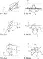
- FIG. 4Ais a schematic side view of a facet joint in the cervical vertebrae.
- FIG. 4Bis a schematic superior view of a facet joint in the cervical vertebrae.
- FIG. 5Ais a schematic side view of a facet joint in the thoracic vertebrae.
- FIG. 5Bis a schematic superior view of a facet joint in the thoracic vertebrae.
- FIG. 6Ais a schematic side view of a facet joint in the lumbar vertebrae.
- FIG. 6Bis a schematic superior view of a facet joint in the lumbar vertebrae.
- FIG. 7is a block diagram of a flexible fastening band according to an embodiment.
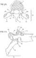
- FIGS. 8-10are posterior perspective views of a portion of the vertebral column depicting a method of stabilizing a vertebra using a flexible fastening band according to an embodiment.
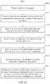
- FIG. 11is a flow chart illustrating a method of using the flexible fastening band depicted FIGS. 8-10 .
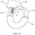
- FIG. 12is a perspective view of a flexible fastening band according to an embodiment.
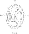
- FIG. 13is a perspective view of a portion of the flexible fastening band depicted in FIG. 12 .
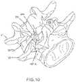
- FIG. 14is a posterior perspective view of a portion of the vertebral column depicting a stabilized vertebra including the flexible fastening band of FIG. 12 according to an embodiment.
- FIG. 15is a perspective view of a spacer according to an embodiment.
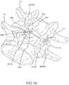
- FIG. 16is a posterior perspective view of a portion of the vertebral column depicting a stabilized vertebra including a flexible fastening band and the spacer of FIG. 15 according to an embodiment.
- FIG. 17is a flow chart illustrating a method of using a flexible fastening band and the spacer of FIG. 15 .
- FIG. 18is a side view of a flexible fastening band according to an embodiment.
- FIG. 19is a top view the flexible fastening band depicted in FIG. 18 .
- FIG. 20is a side view of a flexible fastening band according to an embodiment.
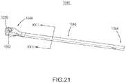
- FIG. 21is a perspective view of a flexible fastening band according to an embodiment.
- FIG. 22is a cross-sectional side view of the flexible fastening band depicted in FIG. 21 .
- FIG. 23is a cross-sectional view taken along line XXIII of the flexible fastening band depicted in FIG. 21 .
- FIG. 24is a cross-sectional top view of the flexible fastening band depicted in FIG. 21 in a first configuration.
- FIG. 25is a cross-sectional top view of the flexible fastening band depicted in FIG. 21 in a second configuration.
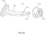
- FIG. 26is an exploded view of a flexible fastening band according to an embodiment.
- FIG. 27is a perspective view of the flexible fastening band depicted in FIG. 26 .
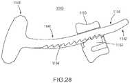
- FIG. 28is a cross-sectional view of the flexible fastening band depicted in FIG. 27 .
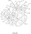
- FIG. 29is a posterior perspective view of a portion of the vertebral column depicting a stabilized vertebra including two flexible fastening bands of FIG. 26 .
- FIG. 30is a posterior perspective view of a portion of the vertebral column depicting a stabilized vertebra including two flexible fastening bands and two spacers according to an embodiment
- a methodcomprises disposing a portion of a flexible fastening band into contact with a first bone portion and into contact with a second bone portion.
- the portion of the flexible fastening bandhaving a substantially uniform shape configured to substantially compliment a shape of the first bone portion and a shape of the second bone portion.
- the methodfurther includes inserting the portion of the flexible fastening band into a fastener and advancing the portion of the flexible fastening band through the fastener until the first bone portion and the and the second bone portion are stabilized.
- an apparatusin some embodiments, includes a flexible elongate body including a proximal end portion, a first portion, a second portion, a reinforcement portion, and a distal end portion.
- the distal end portion of the flexible elongate bodyincludes a fastener configured to accept the proximal end portion and the first portion.
- the second portionincludes a first material
- the reinforcement portionincludes a second material, different from the first material and stronger than the first material.
- the reinforcement pieceis disposed within at least a portion of the second portion.
- an apparatuscomprises a flexible elongate body including a proximal end portion, a first portion, a second portion mutually exclusive from and distal to the first portion, and a distal end portion.
- the apparatusfurther comprises a fastener configured to accept the proximal end portion and the first portion.
- the first portion of the flexible elongate bodyhaving a length and a substantially uniform first shape and the second portion of the flexible elongate body having a length and a substantially uniform second shape, different from the first shape, that is configured to substantially compliment a shape of first bone portion and a shape of a second bone portion.
- the fastenerconfigured to receive the first portion of the flexible elongate body when the second portion of the flexible elongate body is disposed in contact with the first bone portion and in contact with the second bone portion.
- a ratchetis intended to mean a single ratchet or a combination of ratchets.
- a substancecan include any biologic and/or chemical substance, including, but not limited to, medicine, adhesives, etc. While exemplary references are made with respect to vertebra, in some embodiments another bone can be involved. While specific reference may be made to a specific vertebra and/or subset and/or grouping of vertebrae, it is understood that any vertebra and/or subset and/or grouping, or combination of vertebrae can be used.
- the vertebral column 2comprises a series of alternating vertebrae 4 and fibrous discs 6 that provide axial support and movement to the upper portions of the body.
- the vertebral column 2typically comprises thirty-three vertebrae 4 , with seven cervical (C1-C7), twelve thoracic (T1-T12), five lumbar (L1-l5), five fused sacral (S1-S5) and four fused coccygeal vertebrae.
- FIGS. 2A and 2Bdepict a typical thoracic vertebra.
- Each vertebraincludes an anterior body 8 with a posterior arch 10 .
- the posterior arch 10comprises two pedicles 12 and two laminae 14 that join posteriorly to form a spinous process 16 .
- a transverse 18 , superior 20 and inferior articular process 22Projecting from each side of the posterior arch 10 is a transverse 18 , superior 20 and inferior articular process 22 .
- the facets 24 , 26 of the superior 20 and inferior articular processes 22form facet joints 28 with the articular processes of the adjacent vertebrae (see FIGS. 3A and 3B ).
- the facet jointsare true synovial joints with cartilaginous surfaces and a joint capsule.
- the orientation of the facet jointsvary, depending on the level of the vertebral column.
- the facet jointsare parallel to the transverse plane.
- FIGS. 4A to 6Bdepict examples of the orientations of the facet joints at different levels of the vertebral column.
- the facetsare oriented at a 45-degree angle to the transverse plane 30 and parallel to the frontal plane 32 , respectively. This orientation allows the facet joints of the cervical vertebrae to flex, extend, lateral flex and rotate.
- FIGS. 5A and 5Bdepict examples of the thoracic vertebrae, where the facets are oriented at a 60-degree angle to the transverse plane 30 and a 20-degree angle to the frontal plane 32 , respectively. This orientation is capable of providing lateral flexion and rotation, but only limited flexion and extension.
- FIGS. 6A and 6Billustrate examples of the lumbar region, where the facet joints are oriented at 90-degree angles to the transverse plane 30 and a 45-degree angle to the frontal plane 32 , respectively.
- the lumbar vertebraeare capable of flexion, extension and lateral flexion, but little, if any, rotation because of the 90-degree orientation of the facet joints in the transverse plane.
- the actual range of motion along the vertebral columncan vary considerably with each individual vertebra.
- the facet jointsIn addition to guiding movement of the vertebrae, the facet joints also contribute to the load-bearing ability of the vertebral column.
- the facet jointsmay also play a role in resisting shear stresses between the vertebrae. Over time, these forces acting on the facet joints can cause degeneration and arthritis.
- a flexible fastening bandcan be used to stabilize and/or fixate a first vertebra to a second vertebra to reduce the pain, to reduce further degradation of a spine, or of a specific vertebra of a spine, and/or until the first vertebra and the second vertebra have fused.
- FIG. 7depicts a block diagram of a flexible fastening band (“band”) 140 .
- Band 140includes a flexible elongate body including a proximal end portion 142 , a first portion 144 , a second portion 146 , and a distal end portion 148 that includes a fastening mechanism 150 (alternatively referred to herein as a fastener).
- band 140can include a third portion (not shown in FIG. 7 ). In some embodiments, band 140 can include a spacer (not shown in FIG. 7 ). In some embodiments, the fastening mechanism can be separate from the distal end portion (see, e.g., FIGS. 26-30 ).
- Band 140can be configured to stabilize a first vertebra (not shown in FIG. 7 ) and/or a second vertebra (not shown in FIG. 7 ). Specifically, band 140 can be configured to stabilize the first vertebra and/or second vertebra by securing an articular process of the first vertebra to an articular process of a second vertebra.
- band 140can be configured to stabilize the first vertebra and/or a second vertebra by securing an articular process of the first vertebra to an articular process of a second vertebra by securing a facet of the articular process of the first vertebra with a facet of the articular process of the second vertebra.
- band 140can be removed from the vertebra, e.g. by cutting, breaking, or otherwise releasing band 140 . In this manner, should a band fail, a replacement band can be inserted. Similarly, should the band be deemed ineffective for a particular patient, the band can be removed and an alternate treatment can be chosen without incurring permanent fusion of the vertebra.
- band 140can be monolithically formed or separately formed.
- Band 140can include any biocompatible material, e.g., stainless steel, titanium, PEEK, nylon, etc.
- Proximal end portion 142is configured to pass through a lumen formed through a vertebra and a lumen formed through an adjacent vertebra, and to pass through fastening mechanism 150 of the distal end portion 148 .
- proximal end portion 142can be shaped to increase the ease of inserting proximal end portion 142 into fastening mechanism 150 , e.g., proximal end portion 142 can be tapered, rounded, and/or angled, etc, to reduce at least a portion of a cross-sectional area of proximal end portion 142 .
- First portion 144can extend for a length between proximal end portion 142 and second portion 146 , and can have a substantially uniform shape.
- the first portion 144can have, for example, a substantially cuboidal shape, or a substantially cylindrical shape.
- the length of first portion 144can be more than twice the length of second portion 146 .
- the cross-sectional area of the first portion 144can be smaller than the cross-sectional area of the second portion 146 .
- the cross-sectional area of first portion 144can be less than a cross-sectional area of a lumen defined by the fastening mechanism 150 .
- First portion 144can include a gear rack (not shown in FIG.
- the gear rackcan be configured to allow first portion 144 to travel through fastening mechanism 150 in only one direction.
- First portion 144can be monolithically formed with second portion 146 . In some other embodiments, the first portion can be separately formed from the second portion.
- First portion 144can be configured to be slidably disposed in a lumen of second portion 146 .
- Second portion 146can have a length between first portion 144 and distal end portion 148 , and can include a substantially uniform shape. In embodiments including the third portion, second portion 146 can have a length between first portion 144 and the third portion. Second portion 146 can have, for example, a substantially cuboidal shape or a substantially cylindrical shape. First portion 144 and second portion 146 can have the same or different shapes, e.g., first portion 144 and second portion 146 can both be substantially cuboidal (see, e.g., band 240 in FIG. 8 ), first portion 144 and second portion 146 can both be substantially cylindrical (see, e.g., band 840 in FIG.
- first portion 144can be substantially cuboidal while second portion 146 can be substantially cylindrical (see, e.g., band 440 in FIG. 12 ), or first portion 144 can be substantially cylindrical while second portion 146 can be substantially cuboidal (not shown).
- the length of second portion 146can be less than half the length of first portion 144 .
- the cross-sectional area of the second portion 146can be greater than the cross-sectional area of the first portion 144 .
- the cross-sectional area of second portion 146can be greater than a cross-sectional area of a lumen defined by the fastening mechanism 150 .
- Second portion 146can include a gear rack (not shown in FIG. 7 ) configured to engage the ratchet of the fastening mechanism 150 .
- the gear rackcan be configured to allow second portion 46 to travel through fastening mechanism 150 in only one direction.
- Second portion 146can be monolithically formed with first portion 144 . In some embodiments, the second portion can be separately formed from the first portion. Second portion 146 can define a lumen configured to slidably accept first portion 144 .
- Distal end portion 148includes a fastening mechanism 150 configured to accept at least a portion of proximal end portion 142 , first portion 144 , and/or second portion 146 .
- distal end portion 148 , second portion 146 , first portion 144 , and proximal end portion 142can be monolithically formed.
- Fastening mechanism 150includes a lumen (not shown in FIG. 7 ) configured to accept at least a portion of proximal end portion 142 , a portion of first portion 142 , and/or a portion of second portion 146 .
- the cross-sectional area of the lumen of fastening mechanism 150is smaller than the cross-sectional area of second portion 146 .
- fastening mechanismcan include a ratchet (not shown in FIG. 7 ) configured to engage the gear rack of the first portion 144 and/or second portion 146 . In this manner, the fastening mechanism can allow first portion 144 and/or second portion 146 to advance through fastening mechanism 150 in only one direction.
- distal end portion 148 , second portion 146 , first portion 144 , and proximal end portion 142can be formed separately from the other(s) of distal end portion 148 , second portion 146 , first portion 144 , and proximal end portion 142 .
- distal end portion 148 , first portion 144 , and proximal end portion 142can be monolithically formed together, while second portion 146 can be separately formed.
- band 140can include an initial second portion 146 configured to be replaced and/or covered with a replacement second portion 146 .
- initial second portion 146can be monolithically formed with first portion 144 and replacement second portion 146 can be slidably disposed over initial second portion 146 .
- initial second portion 146can be separately formed from first portion 144 , can be removed from band 140 , and replacement second portion 146 can be slidably disposed over first portion 144 .
- initial second portion 146can be separately or monolithically formed from first portion 144 , and replacement second portion 146 can be slidably disposed over first portion 144 and initial second portion 146 .
- initial second portion 146 and replacement second portion 146can have the same shape, e.g., initial second portion 146 can include a substantially cylindrical shape and replacement second portion 146 can include a substantially cylindrical shape. In some embodiments, initial second portion 146 and replacement second portion 146 can have different shapes, e.g., initial second portion 146 can include a substantially cuboidal shape and replacement second portion 146 can include a substantially cylindrical shape.
- the shape of first portion 144 and the shape of second portion 146can be determined based on the shape of an artificial lumen formed through a articular process of a vertebra.
- the shape of the artificial lumenis cuboidal
- the shape of the of the first portion 144 and the shape of the second portion 146can be cuboidal to allow the first portion 144 and the second portion 146 to slidably advance through the artificial lumen.
- the shape of the artificial lumenis cylindrical
- the shape of the first portion 144 and the shape of the second portion 146can be either cuboidal or cylindrical.
- the shape of the first portion 144can be cuboidal to allow the first portion 144 to advance easily through the artificial lumen, while the shape of the second portion 146 can be cylindrical to allow the second portion 146 to fit more tightly within the artificial lumen as compared to a cuboidal shape.
- the shape of the first portion 144 and the shape of the second portion 146can be determined based on characteristics of the bone or bone portion against which the first portion 144 and the second portion 146 may contact.
- first portion 144 and/or second portion 146can be substantially cuboidal
- edges of the first portion 144 and/or the second portion 146can be rounded, partially rounded, and/or otherwise shaped to compliment the shape of a bone or bone portion, and/or to reduce digging or grinding into the bone or bone portion. In this manner, use of band 140 may cause little or no damage to the bone or bone portions contacted by band 140 .
- band 140can include a third portion (not shown in FIG. 7 ).
- the third portioncan have a length between second portion 146 and distal end portion 150 , and can have a substantially uniform shape.
- the third portioncan have, for example, a substantially cuboidal shape or a substantially cylindrical shape.
- the length of the third portioncan be less than half the length of first portion 144 .
- the third portioncan be monolithically formed with first portion 144 and/or the second portion 146 .
- the first portioncan be separately formed from the second portion and/or the first portion.
- first portion 144 , second portion 146 , and the third portioncan be a substantially uniform shape
- any one of first portion 144 , second portion 146 , and the third portioncan include a transition portion to transition band 140 from a first substantially uniform shape to a second substantially uniform shape.
- first portion 144 and the third portioncan be substantially cuboidal and second portion 146 can be substantially cylindrical.
- second portion 146can include an angled, conical, or other shaped transition portion (see, e.g., second portion 446 in FIG. 13 ).
- the bandcan include a spacer (not shown).
- the spacercan be similar to, and have similar features to the embodiments of the prosthesis shown and described in U.S. patent application Ser. No. 12/859,009; filed Aug. 18, 2010, and titled “Vertebral Facet Joint Drill and Method of Use” (referred to as “the '009 application”), and is incorporated herein by reference in its entirety.
- the spacercan be implanted and deployed to restore the space between facets of a superior articular process of a first vertebra and an inferior articular process of an adjacent vertebra.
- the spacercan be implanted and deployed to help stabilize adjacent vertebrae with adhesives, and/or can be implanted and deployed to deliver a medication.
- the spacercan be, for example, substantially disc shaped.
- the spacercan be other shapes, e.g., square, elliptical, or any other shape.
- the spacercan include a first side and a second side. The first side and/or the second side can be, for example, convex, concave, or flat.
- the first side of the spacercan be concave, convex, or flat, and the second side of the spacer can be concave, convex, or flat, for example, the first side can be concave and the second side concave, the first side can be concave and the second side convex, etc.
- the spacercan include the same materials as band 140 .
- the spacercan include substances configured to release medication and/or increase the stability of a vertebra and/or band 140 .
- the substancescan is include a medicine(s) and/or an adhesive(s).
- FIGS. 8-10show posterior perspective views of a portion of the vertebral column during a method for stabilizing adjacent vertebrae using a flexible fastening band (“band”) 240 according to an embodiment.
- a band 240can be used to stabilize a vertebra V 1 and vertebra V 2 via the inferior articular process IAP 1 A of vertebra V 1 and the superior articular process SAP 2 A of vertebra V 2 .
- a flexible fastening band (“band”) 340is used to stabilize a vertebra V 1 and vertebra V 2 via the inferior articular process IAP 1 B of vertebra V 1 and the superior articular process SAP 2 B of vertebra V 2 .
- vertebra V 1 and/or vertebra V 2are stabilized using only one of band 240 or band 340 .
- one of band 240 or band 340can be used to stabilize vertebra V 1 and/or vertebra V 2 via one of via the inferior articular process IAP 1 A of vertebra V 1 and the superior articular process SAP 2 A of vertebra V 2 , or, via the inferior articular process IAP 1 B of vertebra V 1 and the superior articular process SAP 2 B of vertebra V 2 .
- one of band 240 or band 340can be used to stabilize vertebra V 1 and/or vertebra V 2 via both of the inferior articular process IAP 1 A of vertebra V 1 and the superior articular process SAP 2 A of vertebra V 2 , and, the inferior articular process IAP 1 B of vertebra V 1 and the superior articular process SAP 2 B of vertebra V 2 .
- band 240 and band 340can be similar to band 140 described above and can include similar components.
- band 240includes a proximal end portion 242 , a first portion 244 , a second portion 246 , and a distal end portion 248 including a fastening mechanism 250
- band 340includes a proximal end portion (not shown in FIG. 8 ), a first portion, a second portion, and a distal end portion including a fastening mechanism.
- the shapes of first portion 244 , the first portion of band 340 , second portion 246 , and the second portion of band 340can all be cuboidal. As shown in FIG.
- band 240includes a gear rack 247 and gears 264 .
- gears 264can be wedge shaped to allow each of gears 264 to displace the ratchet of fastening mechanism 250 in only one direction.
- gears 264can be other shapes, such as blocks, etc.
- FIG. 11depicts a flow chart illustrating a method 5000 of using band 240 and/or band 340 .
- a patientPrior to use of band 240 and/or band 340 , a patient can be prepared for surgery, at 5002 . Some examples of preparations for surgery are described in the '009 patent.
- the surgical procedurecan include direct visualization of the vertebra(e) to be stabilized. Said another way, the medical practitioner can perform the operation without the use of fluoroscopy, and, in this manner, may not have to rely on the inaccuracies and/or inconvenience inherent in fluoroscopic procedures.
- the surgical procedure usedcan include forming an opening in body tissue substantially equidistant between a first articular process of the first vertebra and a second articular process of the first vertebra.
- a tube(not shown) can be inserted through the opening and a proximal end of the tube can be positioned near the lumen of superior articular process SAP 2 A of vertebra V 2 .
- a drill or other devicecan be used to form a lumen in superior articular process SAP 2 A of vertebra V 2 and inferior articular process IAP 1 A of vertebra V 1 , at 5004 .
- the drillcan be used to form the lumen in a facet of superior articular process SAP 2 A of vertebra V 2 and form the lumen in a facet of inferior articular process IAP 1 A of vertebra V 1 .
- Methods and devices for forming lumens in vertebraare described in the '009 application.
- the band 240can be positioned within the tube and can be advanced through the tube until the proximal end portion 242 is positioned near the lumen of superior articular process SAP 2 A of vertebra V 2 .
- the proximal end of the tubecan have a bend to direct the proximal end portion 242 into the lumen of superior articular process SAP 2 A of vertebra V 2 .
- Proximal end portion 242is inserted into the lumen of superior articular process SAP 2 A of vertebra V 2 and through the lumen of inferior articular process IAP 1 A of vertebra V 1 , at 5006 , and a portion of first portion 244 is advanced through the lumen of superior articular process SAP 2 A of vertebra V 2 and through the lumen of inferior articular process IAP 1 A of vertebra V 1 .
- the tubecan be removed and/or reinserted at various points during the method 5000 , including, for example, after the proximal end portion of band 240 is inserted into the lumen formed within the superior articular process SAP 2 A of vertebra V 2 , after vertebra V 1 and/or Vertebra V 2 has been stabilized, or at other points during method 5000 .
- first portion 244can be advanced through the lumen of superior articular process SAP 2 A of vertebra V 2 and through the lumen of inferior articular process IAP 1 A of vertebra V 1 such that only second portion 246 is within the lumen of superior articular process SAP 2 A of vertebra V 2 and through the lumen of inferior articular process IAP 1 A of vertebra V 1 .
- the lumencan only be contacted by that portion of the band, for example, the second portion, having the same shape.
- proximal end portion 242is inserted into the lumen of fastening mechanism 250 of distal end portion 248 , at 5008 .
- a medical practitionercan grasp proximal end 242 and distal end 248 , and manually insert proximal end portion 242 into fastening mechanism 250 .
- one or both of proximal end portion 242 and distal end portion 248can be grasped with surgical tools (not shown).
- the surgical toolscan be configured to fit specific band configurations, for example, the surgical tools can be configured to receive distal end 248 without obstructing the lumen of fastening mechanism 250 .
- the surgical toolscan be configured to grasp and manipulate proximal end portion 242 and/or first portion 244 .
- a portion of first portion 244is advanced through the lumen of fastening mechanism 250 of distal end portion 248 until superior articular process SAP 2 A of vertebra V 2 and inferior articular process IAP 1 A of vertebra V 1 are stabilized, at 5010 .
- a surgical toolcan be used to advance first portion 244 through the lumen of fastening mechanism 250 .
- one portion of the surgical toolcan be configured to receive distal portion 248 without obstructing the lumen through fastening mechanism 250 , one portion of the surgical tool can be configured to grip and/or advance proximal end portion 242 and or first portion 244 .
- the surgical toolcan be configured to restrict the amount of force and/or torque imparted on band 240 and/or to provide an indication to a medical practitioner of the amount of force and/or torque imparted on the band.
- the amount of force and/or torque imparted on the band, and/or the amount of force and/or torque used to provide and indication to the medical practitionercan be adjusted by the medical practitioner and/or can be determined by the configuration of the band selected for the procedure and/or by the physiology of the patient.
- the first portion 244is prevented from retracting out of fastening mechanism 250 .
- a portion of first portion 244is removed from band 240 .
- a surgical toolcan be used to remove the portion of the band 240 that extends beyond fastening mechanism 250 .
- the surgical toolcan be configured to maintain a grip on the portion of the band 240 that extends beyond the fastening mechanism 250 and is to be removed. In this manner, the location of the removed portion of band 240 can be controlled prior to, and after, removal.
- Band 340can be substantially similar to band 240 as shown in FIG. 10 , and method 270 can be used to implant and deploy band 340 .
- FIG. 12depicts views of a flexible fastening band (“band”) 440
- FIG. 13depicts a view of a portion of band 440
- FIG. 14shows a portion of the vertebral column with adjacent vertebrae stabilized using band 440 and a flexible fastening band (“band”) 540 according to an embodiment.
- a band 440can be used to stabilize a vertebra V 3 and vertebra V 4 via the inferior articular process IAP 3 A of vertebra V 3 and the superior articular process SAP 4 A of vertebra V 4 .
- FIG. 14shows a portion of the vertebral column with adjacent vertebrae stabilized using band 440 and a flexible fastening band (“band”) 540 according to an embodiment.
- a band 540is used to stabilize a vertebra V 3 and vertebra V 4 via the inferior articular process IAP 3 B of vertebra V 3 and the superior articular process SAP 4 B of vertebra V 4 .
- vertebra V 3 and/or vertebra V 3are stabilized using only one of band 440 or band 540 , as described above regarding band 240 and band 340 .
- band 440 and band 540can be similar to bands 140 , 240 , and 340 described above and can include similar components.
- band 440includes a proximal end portion 442 , a first portion 444 , a second portion 446 , and a distal end portion 448 including a fastening mechanism 450
- band 540includes a proximal end portion (not shown in FIG. 14 ), a first portion 544 , a second portion 546 , and a distal end portion 548 including a fastening mechanism 550 .
- band 440 and band 540each includes a cylindrical second portion 446 , 546 , and each includes a third portion 449 , 549 , respectfully.
- third portion 449is substantially the same shape as first portion 442
- third portion 549is substantially the same shape as first portion 542 .
- second portion 446is substantially the same diameter as the diameter of the lumen of superior articular process SAP 4 A of vertebra V 4 and the diameter of the lumen of inferior articular process IAP 3 A of vertebra V 3
- second portion 546is substantially the same diameter as the diameter of the lumen of superior articular process SAP 4 B of vertebra V 4 and the diameter of the lumen of inferior articular process IAP 3 B of vertebra V 3 .
- the diameter of the second portionis substantially the same as the lumen of superior articular process SAP 4 B of vertebra V 4 and the diameter of the lumen of inferior articular process IAP 3 B of vertebra V 3 , the amount of open space within the lumen can be minimized, the amount of surface area of the second portion of the band in contact with the lumen can increase, and subsequently the movement of vertebra V 3 and/or vertebra V 4 can be reduced or minimized. Furthermore, when movement of vertebra V 3 and/or vertebra V 4 does occur, forces acting against the band can be more equally distributed throughout the second portion of the band, due at least to the increased surface area of the band in contact with the lumen. As shown in FIGS.
- band 440includes a gear rack 447 and gears 464 .
- gears 464can be wedge shaped to allow each of gears 464 to displace the ratchet of fastening mechanism 450 in only one direction.
- gears 464can be other shapes, such as blocks, etc.
- FIG. 15depicts a perspective view of a spacer 654
- FIG. 16depicts a portion of the vertebral column depicting a vertebra stabilized using a flexible fastening band (“band”) 640 and spacer 654 , and a flexible fastening band (“band”) 740 and spacer 754 according to an embodiment.
- a band 640can be used to stabilize a vertebra V 5 and vertebra V 6 via the inferior articular process IAP 5 A of vertebra V 5 and the superior articular process SAP 6 A of vertebra V 5 .
- FIG. 16depicts a portion of the vertebral column depicting a vertebra stabilized using a flexible fastening band (“band”) 640 and spacer 654 , and a flexible fastening band (“band”) 740 and spacer 754 according to an embodiment.
- a band 640can be used to stabilize a vertebra V 5 and vertebra V 6 via the inferior articular process IAP 5 A of vertebra V 5 and the superior articular process SAP 6
- a band 740is used to stabilize a vertebra V 6 and vertebra V 5 via the inferior articular process IAP 5 B of vertebra V 5 and the superior articular process SAP 6 B of vertebra V 6 .
- vertebra V 5 and/or vertebra V 6are stabilized using only one of band 640 or band 740 , as described above regarding band 240 and band 340 .
- band 640 and band 740can be similar to bands 140 , 240 , 340 , 440 , and 540 described above and can include similar components.
- band 640can include a spacer 654
- band 740can include a spacer 754 .
- any of bands 140 , 240 , 340 , 440 , and 540can include a spacer similar to spacer 654 and 754 .
- spacer 654can be substantially disc shaped.
- Spacer 654can be can be similar to, and have similar features to the spacer described above and to the embodiments of the prosthesis shown and described in the '009 application.
- Spacer 654can be implanted and deployed to restore the space between facets of a superior articular process of a first vertebra and an inferior articular process of an adjacent vertebra, can be implanted and deployed to help stabilize adjacent vertebrae with adhesives, and/or can be implanted and deployed to deliver a medication.
- the spacercan be, for example, substantially disc shaped.
- the spacercan be other shapes, e.g., square, elliptical, or any other shape.
- Spacer 654include a first side 656 and a second side 658 . As shown in FIG. 15 , first side 656 is concave and second side 658 is convex. In some embodiments, first side 656 and/or the second side 658 can be convex, concave, or flat. Said another way, first side 656 of spacer 654 can be concave, convex, or flat, and second side 658 of spacer 654 can be concave, convex, or flat, e.g., first side 656 is concave and second side 658 is concave, first side 656 concave and second side 658 is convex, etc.
- first side 656 and/or second side 658can fit better against an articular process of a vertebra, specifically against a facet of the articular process of the vertebra.
- Spacer 654can include, for example, the same materials as band 640 .
- spacer 654can include substances configured to release medication and/or increase the stability of a vertebra and/or band 640 .
- the substancescan is include a medicine(s) and/or an adhesive(s).
- FIG. 17depicts a flow chart illustrating a method 6000 of using band 640 and/or band 740 .
- a patientPrior to use of band 640 and band 740 , a patient can be prepared for surgery, at 6002 . Some examples of preparations for surgery are described in the '009 application.
- the surgical procedurecan include direct visualization of the vertebra(e) to be stabilized. Said another way, the medical practitioner can perform the operation without the use of fluoroscopy, and, in this manner, may not have to rely on the inaccuracies and/or inconvenience inherent in fluoroscopic procedures.
- the surgical procedure usedcan include forming an opening in body tissue substantially equidistant between a first articular process of the first vertebra and a second articular process of the first vertebra.
- a tube(not shown) can be inserted through the opening and a proximal end of the tube can be position near the lumen of superior articular process SAP 6 A of vertebra V 6 .
- a drill or other devicecan be used to form a lumen in superior articular process SAP 6 A of vertebra V 6 and inferior articular process IAP 5 A of vertebra V 5 , at 6004 .
- the drillcan be used to form the lumen in a facet of superior articular process SAP 6 A of vertebra V 6 and to form the lumen in a facet of inferior articular process IAP 5 A of vertebra V 5 .
- Methods and devices for forming lumens in vertebraare described in the '009 application.
- the band 640can be positioned within the tube and can be advanced through the tube until the proximal end portion is positioned near the lumen of superior articular process SAP 6 A of vertebra V 6 .
- the proximal end of the tubecan have a bend to direct the proximal end portion into the lumen of superior articular process SAP 6 A of vertebra V 6 .
- the proximal end portionis inserted into the lumen of superior articular process SAP 6 A of vertebra V 6 , at 6006 .
- Spacer 654is inserted between the superior articular process SAP 6 A of vertebra V 6 and inferior articular process IAP 5 A of vertebra V 5 , at 6008 .
- spacer 654can be disposed prior to inserting the proximal end portion into the lumen of superior articular process SAP 6 A of vertebra V 6 .
- the tubecan be removed and/or reinserted at various points during the method 6000 , including, for example, after the proximal end portion of band 640 is inserted into the lumen formed within the superior articular process SAP 6 A of vertebra V 6 , after vertebra V 5 and/or Vertebra V 6 has been stabilized, or at other points during method 6000 .
- first portion 644can be advanced through the lumen of superior articular process SAP 6 A of vertebra V 6 and through the lumen of inferior articular process IAP 5 A of vertebra V 5 such that only the second portion is within the lumen of superior articular process SAP 6 A of vertebra V 6 and through the lumen of inferior articular process IAP 5 A of vertebra V 5 .
- the lumencan only be contacted by that portion of the band, for example, the second portion, having the same shape.
- the proximal end portionis inserted into the lumen of inferior articular process IAP 5 A of vertebra V 5 , at 6010 .
- Proximal end portion 642is inserted into the lumen of fastening mechanism 650 of distal end portion 648 , at 6012 .
- a medical practitionercan grasp the proximal end portion and distal end 648 , and manually insert the proximal end portion into fastening mechanism 650 .
- one or both of the proximal end portion and distal end portion 648can be grasped with surgical tools (not shown).
- the surgical toolscan be configured to fit specific band configuration, for example, the surgical tools can be configured to receive distal end 648 without obstructing the lumen of fastening mechanism 650 .
- the surgical toolscan be configured to grasp and manipulate the proximal end portion and/or first portion 644 .
- a portion of first portion 644is advanced through the lumen of superior articular process SAP 6 A of vertebra V 6 and through the lumen of inferior articular process IAP 5 A of vertebra V 5 .
- a portion of first portion 644is advanced through the lumen of fastening mechanism 650 of distal end portion 648 until superior articular process SAP 6 A of vertebra V 6 and inferior articular process IAP 5 A of vertebra V 5 are stabilized, at 6014 .
- a surgical toolcan be used to advance first portion 644 through the lumen of fastening mechanism 650 .
- one portion of the surgical toolcan be configured to receive distal portion 648 without obstructing the lumen through fastening mechanism 650
- one portion of the surgical toolcan be configured to grip and/or advance the proximal end portion and or first portion 644 .
- the surgical toolcan be configured to restrict the amount of force and/or torque imparted on band 640 and/or to provide an indication to a medical practitioner of the amount of force and/or torque imparted on the band.
- the amount of force and/or torque imparted on the band, and/or the amount of force and/or torque required to provide and indication to the medical practitionercan be adjusted by the medical practitioner and/or can be determined by the configuration of the band selected for the procedure and/or by the physiology of the patient.
- the first portion 644is prevented from retracting out of the fastening mechanism. A portion of first portion 644 is removed from band 640 .
- a surgical toolcan be used to remove the portion of the band 640 that extends beyond fastening mechanism 650 .
- the surgical toolcan be configured to maintain a grip on the portion of the band 640 that extends beyond fastening mechanism 250 and is to be removed. In this manner, the location of the removed portion of band 640 can be controlled prior to, and after, removal.
- Band 740 and spacer 754can be substantially similar to band 640 and spacer 654 , and method 770 can be used to implant and deploy band 740 and spacer 754 .
- FIG. 18is a side view and FIG. 19 is a top view of a flexible fastening band (“band”) 840 according to another embodiment.
- Band 840can be similar to band 140 and band 240 described above and can include similar components.
- band 840includes a proximal end portion 842 , a first portion 844 including a gear rack 847 , a second portion 846 , and a distal end portion 848 including a fastening mechanism 850 and a ratchet 862 .
- gear rack 247a cross sectional area of each gear 864 of gear rack 847 is rectangular in shape instead of wedge shaped.
- first portion 844is cylindrical in shape instead of cuboidal in shape.
- the lumen 866 of the fastening mechanism 850is cylindrical in shape.
- a band according to this embodimentmay be particularly useful in deployments where a single band in used to stabilize adjacent vertebrae.
- the second portioncan be disposed within the lumen of the first articular process of the first vertebra and a portion of the first portion can be disposed within the lumen of the second articular process of the first vertebra.
- the portion of the band within the first articular process of the first vertebra and the portion of the band within in the second articular process of the first vertebracan both have substantially the same shape as the lumen in the first articular process of the first vertebra and the lumen in the second articular process of the first vertebra.
- the amount of open space within the lumenscan be minimized, the amount of surface area of the first portion and/or second portion of the band in contact with the lumens can increase, and subsequently the movement of the first vertebra and/or the second vertebra can be reduced or minimized. Furthermore, when movement of the first vertebra and/or the second vertebra does occur, forces acting against the band can be more equally distributed throughout the first portion and/or the second portion, due at least to the increased surface area of the band in contact with the lumens.
- FIG. 20is a side view a flexible fastening band (“band”) 940 according to an embodiment.
- Band 940can be similar to band 140 , band 240 , and band 840 described above and can include similar components.
- band 940includes a proximal end portion 942 , a first portion 944 including a gear rack 947 , a second portion 946 , and a distal end portion 948 including a fastening mechanism 950 .
- gear rack 847Similar to gear rack 847 , a cross sectional area of each gear 964 of gear rack 947 is rectangular in shape.
- each of gears 964extend the entire circumference of first portion 944 instead of only a portion of the circumference of first portion 844 .
- first portion 944is cylindrical in shape instead of cuboidal in shape.
- the lumen 966 of the fastening mechanism 950is cylindrical in shape.
- a band according to this embodimentmay be particularly useful in deployments where the movement and repositioning of the band after implantation may be difficult. In this manner, because each of the gears can be the entire circumference of the first portion and/or the second portion, the first portion and/or the second portion can enter the fastening mechanism in any radial orientation and still engage the ratchet.
- FIGS. 21-25are views of a flexible fastening band (“band”) 1040 according to another embodiment.
- FIG. 21is a perspective view and FIG. 22 is a cross-sectional side view of band 1040 .
- FIG. 23is a cross-sectional view of band 1040 taken along line XXIII
- FIG. 24is a cross-sectional top view of band 1040 in a first configuration
- FIG. 25is a cross-sectional top view of band 1040 in a second configuration.
- Band 1040can be similar to band 140 and band 240 described above and can include similar components.
- band 1040includes a proximal end portion (not shown), a first portion 1044 including a gear rack 1047 (see FIG. 22 ), a second portion 106 , and a distal end portion 1048 including a fastening mechanism 1050 and a ratchet 1062 .
- band 1040includes a reinforcement piece 1072 .
- Reinforcement piece 1072can include any of the materials described above for band 140 .
- reinforcement piece 1072can include a material stronger than second portion 1046 and/or first portion 1044 , for example, first portion 1044 and second portion 1046 can include PEEK and reinforcement piece 1072 can include titanium.
- reinforcement piece 1072can be disposed within band 1040 approximately along the entire length of second portion 1046 , and a portion of reinforcement piece 1072 can be disposed within the distal end portion 1048 .
- reinforcement piececan include a length along at least a portion of the length of second portion 1046 and/or first portion 1044 but not the distal end portion.
- reinforcement piece 1072can be disposed only within second portion 1046 .
- Reinforcement piece 1072can have a length in first dimension (length), a length in a second dimension (width), and a length in a third dimension (height). As described herein, a reinforcement piece be different shapes that can include more or fewer dimensions.
- the reinforcement piececan be molded within the band. Said another way, in embodiments where the first portion, the second portion, and or the distal end portion are moldable materials, the reinforcement piece can be placed in the mold and the moldable materials can be injected or otherwise put in the mold around the reinforcement piece.
- each portion of the band (for example, the proximal end portion, the first portion, the second portion, the third portion, and/or the distal end portion) around the reinforcement piececan have a top half and a bottom half, and each of the top half and the bottom half can be placed around the reinforcement piece, and sealed.
- reinforcement piece 1072includes support members 1074 . While FIG.
- reinforcement piece 1072including four support members 1074 , in some embodiments, more or fewer support members 1074 can be used.
- Support members 1074can maintain the position of reinforcement piece 1072 during the molding and/or assembly process of band 1040 . As shown in FIG. 25 , support members 1074 are removed before band 1040 is used.
- reinforcement piece 1072can has a substantially uniform cuboidal shape. In other embodiments, reinforcement piece 1072 can have other shapes.
- the shape of the reinforcement piececan be selected depending on the desired bending and/or torsion characteristics of the material chosen.
- a substantially planar cuboidal shapecan provide a greater increase in bending strength while providing a lesser increase in torsion strength
- a cylindrical shapecan provide an increase in bending strength while providing very little increase in torsion strength
- a substantially square and/or tubular cuboidal shapecan provide similar bending and torsion increases. Any shape can be selected to achieve the desired bending and torsion strength. Combinations of materials and shapes can also be considered.
- reinforcement piece 1072includes holes 1076 distributed along the length of the first dimension. While FIGS. 24 and 25 shows band 1040 including many holes 1076 , in some embodiments, more or fewer holes 1076 can be used. FIGS. 24 and 25 depict holes 1076 distributed substantially equally along the length of the first dimension, in some embodiments, the holes can be distributed differently or along different dimensions depending on the shape and/or material chosen, and/or whether the reinforcement piece is solid or hollow. Holes 1076 can be configured to reduce the weight of reinforcement piece 1072 while still provided band 1040 additional strength. Holes 1076 can be round, oval, square, or any other shape.
- FIG. 26is an exploded view
- FIG. 27is a perspective view
- FIG. 28is a cross-sectional view of a flexible fastening band (“band”) 1140 according to another embodiment.
- Band 1140can be similar to band 140 and band 240 described above and can include similar components.
- band 1140includes a proximal end portion 1142 , a first portion 1144 , a second portion 1146 including a gear rack 1147 , a distal end portion 1148 , a fastening mechanism 1150 and a ratchet 1162 .
- the fastening mechanism 1150 of band 1140is separately formed from band 1140 . While second portion 1146 of band 1140 is shown in FIGS.
- second portion 1146can be substantially cylindrical in shape or any other appropriate shape discussed herein.
- band 1140includes a gear rack 1147 and gears 1164 .
- gears 1164can be wedge shaped to allow each of gears 1164 to displace a ratchet 1162 of fastening mechanism 1150 in only one direction.
- gears 1164can be other shapes, such as blocks, or any other appropriate shape discussed herein.
- distal end portion 1148can be substantially circular in shape and can have a diameter greater than a width of second portion 1146 . In other embodiments, distal portion 1148 can have other shapes, for example, oval, rectangular, square, etc.
- FIG. 29shows a posterior perspective view of a portion of the vertebral column during a method for stabilizing adjacent vertebrae using band 1140 and a flexible fastening band (“band”) 1240 according to an embodiment.
- Band 1240can be similar to band 1140 described above and can include similar components.
- band 1240includes a proximal end portion 1242 , a first portion 1244 , a second portion 1246 , a distal end portion 1248 , and a fastening mechanism 1250 .
- a band 1140can be used to stabilize a vertebra V 11 and a vertebra V 12 via the inferior articular process IAP 11 A of vertebra V 11 and the superior articular process SAP 12 A of vertebra V 12 .
- band 1240is used to stabilize a vertebra V 11 and vertebra V 12 via the inferior articular process IAP 11 B of vertebra V 11 and the superior articular process SAP 12 B of vertebra V 12 .
- vertebra V 11 and/or vertebra V 12are stabilized using only one of band 1140 or band 1240 .
- one of band 1140 or band 1240can be used to stabilize vertebra V 11 and/or vertebra V 12 via one of via the inferior articular process IAP 11 A of vertebra V 11 and the superior articular process SAP 12 A of vertebra V 12 , or, via the inferior articular process IAP 11 B of vertebra V 11 and the superior articular process SAP 12 B of vertebra V 12 .
- band 1140 and/or band 1240can be used in accordance with any of the methods described herein.
- second portion 1146 of band 1140can be disposed in a lumen of IAP 11 A of vertebra V 11 and in a lumen of SAP 12 A of vertebra V 12 .
- Proximal end portion 1142is inserted into a lumen of fastening mechanism 1150 .
- a medical practitionercan grasp proximal end portion 1142 and fastening mechanism 1150 , and manually insert proximal end portion 1142 into fastening mechanism 1150 .
- proximal end portion 1142 and fastening mechanism 1150can be grasped with surgical tools (not shown).
- the surgical toolscan be configured to fit specific band configuration, for example, the surgical tools can be configured to receive fastening mechanism 1150 without obstructing the lumen of fastening mechanism 1150 .
- a portion of first portion 1144is advanced through the lumen of fastening mechanism 1150 until superior articular process SAP 12 A of vertebra V 12 and inferior articular process IAP 11 A of vertebra V 11 are stabilized.
- FIG. 30shows a posterior perspective view of a portion of the vertebral column during a method for stabilizing adjacent vertebrae using a flexible fastening band (“band”) 1340 and a flexible fastening band (“band”) 1440 according to an embodiment.
- band 1340 and band 1440can be similar to band 1140 described above and can include similar components.
- band 1340includes a proximal end portion 1342 , a first portion 1344 , a second portion (not shown in FIG. 30 ), a distal end portion 1348 , and a fastening mechanism 1350 ;
- band 1440includes a proximal end portion 1442 , a first portion 1444 , a second portion (not shown in FIG.
- band 1340includes a spacer 1354
- band 1440includes a spacer 1454 .
- Each of spacer 1354 and spacer 1454can be similar to can be similar to spacer 654 described above and can include similar components.
- a band 1340can be used to stabilize a vertebra V 13 and a vertebra V 14 via the inferior articular process IAP 13 A of vertebra V 13 and the superior articular process SAP 14 A of vertebra V 14 .
- band 1440is used to stabilize a vertebra V 13 and vertebra V 14 via the inferior articular process IAP 13 B of vertebra V 13 and the superior articular process SAP 14 B of vertebra V 14 .
- vertebra V 13 and/or vertebra V 14are stabilized using only one of band 1340 or band 1440 .
- one of band 1340 or band 1440can be used to stabilize vertebra V 13 and/or vertebra V 14 via one of via the inferior articular process IAP 13 A of vertebra V 13 and the superior articular process SAP 14 A of vertebra V 14 , or, via the inferior articular process IAP 13 B of vertebra V 13 and the superior articular process SAP 14 B of vertebra V 14 .
- band 1340 and/or band 1440can be used in accordance with any of the methods described herein.
- the second portion of band 1340can be disposed in a lumen of IAP 13 A of vertebra V 13
- spacer 1354can be disposed between IAP 13 A and SAP 14 A
- the second portion of band 1340can be disposed in a lumen of SAP 14 A of vertebra V 14
- Proximal end portion 1342is inserted into a lumen of fastening mechanism 1350 .
- proximal end portion 1342to insert proximal end portion 1342 into fastening mechanism 1350 , a medical practitioner can grasp proximal end portion 1342 and fastening mechanism 1350 , and manually insert proximal end portion 1342 into fastening mechanism 1350 .
- one or both of proximal end portion 1342 and fastening mechanism 1350can be grasped with surgical tools (not shown).
- the surgical toolscan be configured to fit specific band configuration, for example, the surgical tools can be configured to receive fastening mechanism 1350 without obstructing the lumen of fastening mechanism 1350 .
- a portion of first portion 1344is advanced through the lumen of fastening mechanism 1350 until superior articular process SAP 14 A of vertebra V 14 and inferior articular process IAP 13 A of vertebra V 13 are stabilized.
- a flexible fastening bandcan be used to stabilize and/or fixate an intramedullary (IM) rod or nail.
- IMintramedullary
- the flexible fastening bandcan be used at different longitudinal locations along an IM rod or nail, and used to couple adjacent bone portions to the IM rod or nail.
- a given flexible fastening bandcan fix a first bone portion, the IM rod or nail, and a second bone portion, all of which are positioned between the distal portion and the proximal portion of the flexible fastening band.
- a flexible fastening bandcan be used to stabilize and/or fixate a bone fragment. While various embodiments have been described above with regard to natural bone spaces, (e.g., the space between an inferior articulate process and a superior articulate process), in other embodiments, the bone spacing can be man-made (e.g., sternum split during a heart procedure), and/or due to an injury (e.g., broken bone).
- FIGS. 18 and 19depict band 840 including a single ratchet 862
- FIG. 20depicts band 940 including a single ratchet 962
- any of bands 140 - 1440can include any number of ratchets.
- any of bands 140 - 1440can include a reinforcement piece and/or a spacer.
Landscapes
- Health & Medical Sciences (AREA)
- Orthopedic Medicine & Surgery (AREA)
- Life Sciences & Earth Sciences (AREA)
- Surgery (AREA)
- Neurology (AREA)
- Heart & Thoracic Surgery (AREA)
- Engineering & Computer Science (AREA)
- Biomedical Technology (AREA)
- Nuclear Medicine, Radiotherapy & Molecular Imaging (AREA)
- Medical Informatics (AREA)
- Molecular Biology (AREA)
- Animal Behavior & Ethology (AREA)
- General Health & Medical Sciences (AREA)
- Public Health (AREA)
- Veterinary Medicine (AREA)
- Surgical Instruments (AREA)
- Prostheses (AREA)
- Clamps And Clips (AREA)
Abstract
Description
Claims (20)
Priority Applications (2)
| Application Number | Priority Date | Filing Date | Title |
|---|---|---|---|
| US16/436,118US11464551B2 (en) | 2011-02-24 | 2019-06-10 | Methods and apparatus for stabilizing bone |
| US17/820,690US12343048B2 (en) | 2011-02-24 | 2022-08-18 | Methods and apparatus for stabilizing bone |
Applications Claiming Priority (5)
| Application Number | Priority Date | Filing Date | Title |
|---|---|---|---|
| US13/033,791US8740949B2 (en) | 2011-02-24 | 2011-02-24 | Methods and apparatus for stabilizing bone |
| US14/256,532US9179943B2 (en) | 2011-02-24 | 2014-04-18 | Methods and apparatus for stabilizing bone |
| US14/869,793US9808294B2 (en) | 2011-02-24 | 2015-09-29 | Methods and apparatus for stabilizing bone |
| US15/726,775US10368921B2 (en) | 2011-02-24 | 2017-10-06 | Methods and apparatus for stabilizing bone |
| US16/436,118US11464551B2 (en) | 2011-02-24 | 2019-06-10 | Methods and apparatus for stabilizing bone |
Related Parent Applications (1)
| Application Number | Title | Priority Date | Filing Date |
|---|---|---|---|
| US15/726,775ContinuationUS10368921B2 (en) | 2011-02-24 | 2017-10-06 | Methods and apparatus for stabilizing bone |
Related Child Applications (1)
| Application Number | Title | Priority Date | Filing Date |
|---|---|---|---|
| US17/820,690ContinuationUS12343048B2 (en) | 2011-02-24 | 2022-08-18 | Methods and apparatus for stabilizing bone |
Publications (2)
| Publication Number | Publication Date |
|---|---|
| US20190328428A1 US20190328428A1 (en) | 2019-10-31 |
| US11464551B2true US11464551B2 (en) | 2022-10-11 |
Family
ID=46719511
Family Applications (7)
| Application Number | Title | Priority Date | Filing Date |
|---|---|---|---|
| US13/033,791Active2032-03-28US8740949B2 (en) | 2011-02-24 | 2011-02-24 | Methods and apparatus for stabilizing bone |
| US13/211,052Active2034-03-12US9301786B2 (en) | 2011-02-24 | 2011-08-16 | Methods and apparatus for stabilizing bone |
| US14/256,532ActiveUS9179943B2 (en) | 2011-02-24 | 2014-04-18 | Methods and apparatus for stabilizing bone |
| US14/869,793Active2031-03-31US9808294B2 (en) | 2011-02-24 | 2015-09-29 | Methods and apparatus for stabilizing bone |
| US15/726,775ActiveUS10368921B2 (en) | 2011-02-24 | 2017-10-06 | Methods and apparatus for stabilizing bone |
| US16/436,118Active2031-04-26US11464551B2 (en) | 2011-02-24 | 2019-06-10 | Methods and apparatus for stabilizing bone |
| US17/820,690Active2032-01-19US12343048B2 (en) | 2011-02-24 | 2022-08-18 | Methods and apparatus for stabilizing bone |
Family Applications Before (5)
| Application Number | Title | Priority Date | Filing Date |
|---|---|---|---|
| US13/033,791Active2032-03-28US8740949B2 (en) | 2011-02-24 | 2011-02-24 | Methods and apparatus for stabilizing bone |
| US13/211,052Active2034-03-12US9301786B2 (en) | 2011-02-24 | 2011-08-16 | Methods and apparatus for stabilizing bone |
| US14/256,532ActiveUS9179943B2 (en) | 2011-02-24 | 2014-04-18 | Methods and apparatus for stabilizing bone |
| US14/869,793Active2031-03-31US9808294B2 (en) | 2011-02-24 | 2015-09-29 | Methods and apparatus for stabilizing bone |
| US15/726,775ActiveUS10368921B2 (en) | 2011-02-24 | 2017-10-06 | Methods and apparatus for stabilizing bone |
Family Applications After (1)
| Application Number | Title | Priority Date | Filing Date |
|---|---|---|---|
| US17/820,690Active2032-01-19US12343048B2 (en) | 2011-02-24 | 2022-08-18 | Methods and apparatus for stabilizing bone |
Country Status (5)
| Country | Link |
|---|---|
| US (7) | US8740949B2 (en) |
| EP (1) | EP2677948B1 (en) |
| JP (2) | JP6066930B2 (en) |
| AU (1) | AU2012222229C1 (en) |
| WO (1) | WO2012116266A1 (en) |
Cited By (6)
| Publication number | Priority date | Publication date | Assignee | Title |
|---|---|---|---|---|
| US11918258B2 (en) | 2013-09-27 | 2024-03-05 | Spinal Elements, Inc. | Device and method for reinforcement of a facet |
| US11998240B2 (en) | 2014-09-17 | 2024-06-04 | Spinal Elements, Inc. | Flexible fastening band connector |
| US12232778B2 (en) | 2020-02-14 | 2025-02-25 | Spinal Elements, Inc. | Bone tie methods |
| US12343048B2 (en) | 2011-02-24 | 2025-07-01 | Spinal Elements, Inc. | Methods and apparatus for stabilizing bone |
| US12369952B2 (en) | 2021-12-10 | 2025-07-29 | Spinal Elements, Inc. | Bone tie and portal |
| US12440242B2 (en) | 2024-04-29 | 2025-10-14 | Spinal Elements, Inc. | Flexible fastening band connector |
Families Citing this family (30)
| Publication number | Priority date | Publication date | Assignee | Title |
|---|---|---|---|---|
| US7846183B2 (en)* | 2004-02-06 | 2010-12-07 | Spinal Elements, Inc. | Vertebral facet joint prosthesis and method of fixation |
| US9504583B2 (en) | 2004-06-10 | 2016-11-29 | Spinal Elements, Inc. | Implant and method for facet immobilization |
| WO2006058221A2 (en) | 2004-11-24 | 2006-06-01 | Abdou Samy M | Devices and methods for inter-vertebral orthopedic device placement |
| US8992533B2 (en) | 2007-02-22 | 2015-03-31 | Spinal Elements, Inc. | Vertebral facet joint drill and method of use |
| EP2813190B1 (en) | 2007-02-22 | 2017-04-26 | Spinal Elements, Inc. | Vertebral facet joint drill |
| US9271765B2 (en) | 2011-02-24 | 2016-03-01 | Spinal Elements, Inc. | Vertebral facet joint fusion implant and method for fusion |
| USD724733S1 (en) | 2011-02-24 | 2015-03-17 | Spinal Elements, Inc. | Interbody bone implant |
| USD739935S1 (en) | 2011-10-26 | 2015-09-29 | Spinal Elements, Inc. | Interbody bone implant |
| EP2830512B1 (en) | 2012-03-28 | 2016-08-03 | Synthes GmbH | Bone fixation member systems |
| US9597132B2 (en) | 2013-01-12 | 2017-03-21 | Louis Houff | Sternum fixation device and method |
| CA2899167C (en)* | 2013-01-25 | 2021-08-31 | DePuy Synthes Products, Inc. | Caps for implants, implant assemblies, and methods of use |
| WO2014149244A1 (en) | 2013-02-07 | 2014-09-25 | Houff Louis | Sternum fixation device and method |
| US9131968B2 (en) | 2013-02-27 | 2015-09-15 | Biomet C.V. | Periprosthetic plating system including plate with system for retaining tension on a cable |
| US9820784B2 (en)* | 2013-03-14 | 2017-11-21 | Spinal Elements, Inc. | Apparatus for spinal fixation and methods of use |
| US9421044B2 (en)* | 2013-03-14 | 2016-08-23 | Spinal Elements, Inc. | Apparatus for bone stabilization and distraction and methods of use |
| US9730737B2 (en)* | 2013-03-14 | 2017-08-15 | Atlas Spine, Inc. | Facet fixation with anchor wire |
| USD765853S1 (en) | 2013-03-14 | 2016-09-06 | Spinal Elements, Inc. | Flexible elongate member with a portion configured to receive a bone anchor |
| US9456855B2 (en) | 2013-09-27 | 2016-10-04 | Spinal Elements, Inc. | Method of placing an implant between bone portions |
| EP3226791B1 (en) | 2015-01-26 | 2020-03-04 | Panther Orthopedics, Inc. | Active tension bone and joint stabilization devices |
| AU2016212009C1 (en) | 2015-01-27 | 2021-02-25 | Spinal Elements, Inc. | Facet joint implant |
| CN107613884A (en) | 2015-03-25 | 2018-01-19 | 克拉克伊德解决方案有限公司 | Joint Repair System |
| CA3070372A1 (en) | 2017-08-09 | 2019-02-14 | Panther Orthopedics, Inc. | Active bone and joint stabilization device features |
| US11071569B2 (en)* | 2017-08-10 | 2021-07-27 | Ortho Development Corporation | Nesting tether clamping assemblies and related methods and apparatus |
| CA3136826A1 (en)* | 2019-04-23 | 2020-10-29 | Panther Orthopedics, Inc. | Strength and fatigue life improvements for active bone and joint stabilization devices |
| BR112021022695A2 (en) | 2019-05-22 | 2021-12-28 | Spinal Elements Inc | Bone tethering and bone tethering inserter |
| US11457959B2 (en) | 2019-05-22 | 2022-10-04 | Spinal Elements, Inc. | Bone tie and bone tie inserter |
| WO2021144128A1 (en)* | 2020-01-17 | 2021-07-22 | Westfaelische Wilhelms-Universitaet Muenster | Bone repair system |
| US11337741B2 (en) | 2020-05-01 | 2022-05-24 | Sergio Lenchig | Laterally deployed kyphoplasty balloon tamponade |
| US12290295B2 (en) | 2020-06-19 | 2025-05-06 | Circumfix Solutions, Inc. | Bone repair devices and methods |
| MX2024001359A (en) | 2021-07-29 | 2024-04-30 | Circumfix Solutions Inc | BONE REPAIR DEVICES AND METHODS. |
Citations (499)
| Publication number | Priority date | Publication date | Assignee | Title |
|---|---|---|---|---|
| US86016A (en) | 1869-01-19 | Silas j | ||
| US1630239A (en) | 1924-05-09 | 1927-05-24 | Roy S Binkley | Antrum burr |
| US1822280A (en) | 1929-06-26 | 1931-09-08 | John F Ervay | Carpenter's hammer |
| US1822330A (en) | 1930-01-13 | 1931-09-08 | Ainslie George | Suturing instrument |
| US2486303A (en) | 1948-04-29 | 1949-10-25 | Harry Herschel Leiter | Surgical appliance for bone fractures |
| US2706023A (en) | 1952-01-02 | 1955-04-12 | Ronald A Merritt | Gripping device for securing guy wires to a mast |
| US2967282A (en) | 1957-09-30 | 1961-01-03 | Gen Electric | High temperature resistor |
| US3111945A (en) | 1961-01-05 | 1963-11-26 | Solbrig Charles R Von | Bone band and process of applying the same |
| US3149808A (en) | 1963-09-25 | 1964-09-22 | Weckesser Co | Wedge-lock band clamp |
| US3570497A (en) | 1969-01-16 | 1971-03-16 | Gerald M Lemole | Suture apparatus and methods |
| US3867728A (en) | 1971-12-30 | 1975-02-25 | Cutter Lab | Prosthesis for spinal repair |
| US3875595A (en) | 1974-04-15 | 1975-04-08 | Edward C Froning | Intervertebral disc prosthesis and instruments for locating same |
| US3879767A (en) | 1972-01-26 | 1975-04-29 | Cutter Lab | Prosthesis for articulating body structures |
| US4001896A (en) | 1975-06-09 | 1977-01-11 | Zimmer, U.S.A. Inc. | Prosthetic joint for total knee replacement |
| US4037603A (en) | 1975-05-13 | 1977-07-26 | Wendorff Erwin R | Metallic surgical suture |
| JPS535889A (en) | 1976-07-06 | 1978-01-19 | Partridge Anthony John | Orthopedic surgical operation band and bone setting method |
| US4085466A (en) | 1974-11-18 | 1978-04-25 | National Research Development Corporation | Prosthetic joint device |
| US4156296A (en) | 1977-04-08 | 1979-05-29 | Bio-Dynamics, Inc. | Great (large) toe prosthesis and method of implanting |
| US4164793A (en) | 1978-04-26 | 1979-08-21 | Swanson Alfred B | Lunate implant |
| US4166292A (en) | 1977-09-08 | 1979-09-04 | Carbomedics, Inc. | Stress reinforced artificial joint prostheses |
| US4231121A (en) | 1979-07-05 | 1980-11-04 | Wright Dow Corning | Metacarpal-phalangeal prosthesis |
| USD261935S (en) | 1978-12-18 | 1981-11-17 | Halloran William X | Slotted intramedullary rod |
| US4312337A (en) | 1980-09-08 | 1982-01-26 | Donohue Brian T | Cannula and drill guide apparatus |
| US4323217A (en) | 1980-01-30 | 1982-04-06 | General Electric Company | Motor mounting assembly including extendable band |
| US4349921A (en) | 1980-06-13 | 1982-09-21 | Kuntz J David | Intervertebral disc prosthesis |
| US4502161A (en) | 1981-09-21 | 1985-03-05 | Wall W H | Prosthetic meniscus for the repair of joints |
| USD279502S (en) | 1982-11-26 | 1985-07-02 | Halloran William X | Intramedullary rod having a s-shaped cross section |
| USD279503S (en) | 1982-11-26 | 1985-07-02 | Halloran William X | Grooved intramedullary rod |
| US4535764A (en) | 1983-04-15 | 1985-08-20 | Tayco Developments, Inc. | Surgical bone tie |
| US4570618A (en) | 1983-11-23 | 1986-02-18 | Henry Ford Hospital | Intervertebral body wire stabilization |
| US4573459A (en) | 1983-08-25 | 1986-03-04 | Litton Bruce W | Thumb and finger extension device |
| US4573458A (en) | 1982-08-17 | 1986-03-04 | Zimmer, Inc. | Bone fixation plate |
| US4634445A (en) | 1981-01-30 | 1987-01-06 | Oec Europe Limited | Joint prosthesis |
| US4643178A (en) | 1984-04-23 | 1987-02-17 | Fabco Medical Products, Inc. | Surgical wire and method for the use thereof |
| US4662371A (en) | 1983-01-26 | 1987-05-05 | Whipple Terry L | Surgical instrument |
| EP0238219A1 (en) | 1986-03-03 | 1987-09-23 | Pfizer Hospital Products Group, Inc. | A sternum closure device |
| US4706659A (en) | 1984-12-05 | 1987-11-17 | Regents Of The University Of Michigan | Flexible connecting shaft for intramedullary reamer |
| US4714469A (en) | 1987-02-26 | 1987-12-22 | Pfizer Hospital Products Group, Inc. | Spinal implant |
| US4722331A (en) | 1985-09-03 | 1988-02-02 | Fox James M | Orthopaedic tool guide |
| US4759766A (en) | 1984-09-04 | 1988-07-26 | Humboldt-Universitaet Zu Berlin | Intervertebral disc endoprosthesis |
| US4759769A (en) | 1987-02-12 | 1988-07-26 | Health & Research Services Inc. | Artificial spinal disc |
| WO1988006022A1 (en) | 1987-02-20 | 1988-08-25 | Farrell Edward M | Surgical tying devices |
| US4772287A (en) | 1987-08-20 | 1988-09-20 | Cedar Surgical, Inc. | Prosthetic disc and method of implanting |
| US4773402A (en) | 1985-09-13 | 1988-09-27 | Isola Implants, Inc. | Dorsal transacral surgical implant |
| US4834757A (en) | 1987-01-22 | 1989-05-30 | Brantigan John W | Prosthetic implant |
| EP0322334A1 (en) | 1987-12-23 | 1989-06-28 | Cremascoli France | Prosthesis implanted between vertebral spinous processes |
| US4863477A (en) | 1987-05-12 | 1989-09-05 | Monson Gary L | Synthetic intervertebral disc prosthesis |
| US4880429A (en) | 1987-07-20 | 1989-11-14 | Stone Kevin R | Prosthetic meniscus |
| US4907577A (en) | 1989-04-03 | 1990-03-13 | Wu Shing Sheng | Spinal transpedicle drill jig |
| US4911718A (en) | 1988-06-10 | 1990-03-27 | University Of Medicine & Dentistry Of N.J. | Functional and biocompatible intervertebral disc spacer |
| US4919667A (en) | 1988-12-02 | 1990-04-24 | Stryker Corporation | Implant |
| US4923471A (en) | 1989-10-17 | 1990-05-08 | Timesh, Inc. | Bone fracture reduction and fixation devices with identity tags |
| US4936848A (en) | 1989-09-22 | 1990-06-26 | Bagby George W | Implant for vertebrae |
| US4941466A (en) | 1987-04-13 | 1990-07-17 | Romano Jack W | Curved bore drilling method and apparatus |
| US4955913A (en) | 1985-03-28 | 1990-09-11 | Robinson Walter C | Surgical tie |
| US4959065A (en) | 1989-07-14 | 1990-09-25 | Techmedica, Inc. | Bone plate with positioning member |
| EP0392124A1 (en) | 1987-11-16 | 1990-10-17 | Francis Henri Bréard | Surgical implant for limiting the relative movement of vertebrae |
| US4969909A (en) | 1987-10-27 | 1990-11-13 | Barouk Louis S | Articular prosthetic implant with temporary fixing means |
| US5000165A (en) | 1989-05-15 | 1991-03-19 | Watanabe Robert S | Lumbar spine rod fixation system |
| US5002546A (en) | 1987-04-13 | 1991-03-26 | Romano Jack W | Curved bore drilling apparatus |
| JPH03100154A (en) | 1989-09-13 | 1991-04-25 | Kawasaki Steel Corp | Production of alloying hot dip galvanized steel strip |
| US5015255A (en) | 1989-05-10 | 1991-05-14 | Spine-Tech, Inc. | Spinal stabilization method |
| US5047055A (en) | 1990-12-21 | 1991-09-10 | Pfizer Hospital Products Group, Inc. | Hydrogel intervertebral disc nucleus |
| JPH03240660A (en) | 1990-02-02 | 1991-10-28 | Yazaki Corp | Focusing tool |
| US5071437A (en) | 1989-02-15 | 1991-12-10 | Acromed Corporation | Artificial disc |
| US5092866A (en) | 1989-02-03 | 1992-03-03 | Breard Francis H | Flexible inter-vertebral stabilizer as well as process and apparatus for determining or verifying its tension before installation on the spinal column |
| US5092868A (en) | 1987-07-17 | 1992-03-03 | Mehdian Seyed M H | Apparatus for use in the treatment of spinal disorders |
| US5112013A (en) | 1991-02-25 | 1992-05-12 | Chrysler Corporation | Tie strap structure for electric wiring |
| US5112346A (en) | 1989-06-08 | 1992-05-12 | Richard Wolf Gmbh | Retrograde cutting hook punch |
| US5127912A (en) | 1990-10-05 | 1992-07-07 | R. Charles Ray | Sacral implant system |
| US5135188A (en) | 1990-02-06 | 1992-08-04 | Anderson Franklin R | Attachable bundling strap |
| US5147404A (en) | 1987-12-07 | 1992-09-15 | Downey Ernest L | Vertebra prosthesis |
| US5171280A (en) | 1990-04-20 | 1992-12-15 | Sulzer Brothers Limited | Intervertebral prosthesis |
| US5192327A (en) | 1991-03-22 | 1993-03-09 | Brantigan John W | Surgical prosthetic implant for vertebrae |
| US5192326A (en) | 1990-12-21 | 1993-03-09 | Pfizer Hospital Products Group, Inc. | Hydrogel bead intervertebral disc nucleus |
| US5209755A (en) | 1992-06-05 | 1993-05-11 | Stella Abrahan | Dermal exciser |
| DE9304368U1 (en) | 1993-03-18 | 1993-05-13 | AAP GmbH & Co. Betriebs KG, 1000 Berlin | Spinal implant |
| WO1993014721A1 (en) | 1992-01-28 | 1993-08-05 | Salut, Ltd. | Sacral implant system |
| US5258031A (en) | 1992-01-06 | 1993-11-02 | Danek Medical | Intervertebral disk arthroplasty |
| US5282861A (en) | 1992-03-11 | 1994-02-01 | Ultramet | Open cell tantalum structures for cancellous bone implants and cell and tissue receptors |
| US5286249A (en) | 1989-10-31 | 1994-02-15 | Thibodaux Peggy L | Brace for fixation of bone fractures |
| WO1994004088A1 (en) | 1992-08-19 | 1994-03-03 | Surgicraft Limited | Surgical implants, etc |
| US5304178A (en) | 1992-05-29 | 1994-04-19 | Acromed Corporation | Sublaminar wire |
| US5306308A (en) | 1989-10-23 | 1994-04-26 | Ulrich Gross | Intervertebral implant |
| US5306275A (en) | 1992-12-31 | 1994-04-26 | Bryan Donald W | Lumbar spine fixation apparatus and method |
| US5306309A (en) | 1992-05-04 | 1994-04-26 | Calcitek, Inc. | Spinal disk implant and implantation kit |
| US5326364A (en) | 1992-12-16 | 1994-07-05 | Wright Medical Technology, Inc. | Trapezial implant |
| US5330479A (en) | 1993-03-11 | 1994-07-19 | Whitmore Henry B | Reciprocating bone punch |
| EP0610837A1 (en) | 1993-02-09 | 1994-08-17 | Acromed Corporation | Spine disc |
| US5360431A (en) | 1990-04-26 | 1994-11-01 | Cross Medical Products | Transpedicular screw system and method of use |
| FR2704745A1 (en) | 1993-05-07 | 1994-11-10 | Erpios | Device for connecting the ends of a ligament for osteosynthesis, in particular for vertebral osteosynthesis. |
| US5368596A (en) | 1992-03-18 | 1994-11-29 | Burkhart; Stephen S. | Augmented awl for creating channels in human bone tissue |
| US5370697A (en) | 1992-04-21 | 1994-12-06 | Sulzer Medizinaltechnik Ag | Artificial intervertebral disk member |
| US5372598A (en) | 1987-05-14 | 1994-12-13 | Howmedica Gmbh | Small bone plate for cranial or facial fractures or the like |
| US5400784A (en) | 1993-10-15 | 1995-03-28 | Case Western Reserve University | Slowly penetrating inter-fascicular nerve cuff electrode and method of using |
| US5401269A (en) | 1992-03-13 | 1995-03-28 | Waldemar Link Gmbh & Co. | Intervertebral disc endoprosthesis |
| US5413576A (en) | 1993-02-10 | 1995-05-09 | Rivard; Charles-Hilaire | Apparatus for treating spinal disorder |
| US5415661A (en) | 1993-03-24 | 1995-05-16 | University Of Miami | Implantable spinal assist device |
| US5425773A (en) | 1992-01-06 | 1995-06-20 | Danek Medical, Inc. | Intervertebral disk arthroplasty device |
| US5437672A (en) | 1992-11-12 | 1995-08-01 | Alleyne; Neville | Spinal cord protection device |
| US5445639A (en) | 1989-05-10 | 1995-08-29 | Spine-Tech, Inc. | Intervertebral reamer construction |
| US5458642A (en) | 1994-01-18 | 1995-10-17 | Beer; John C. | Synthetic intervertebral disc |
| US5458643A (en) | 1991-03-29 | 1995-10-17 | Kyocera Corporation | Artificial intervertebral disc |
| US5462542A (en) | 1994-01-24 | 1995-10-31 | United States Surgical Corporation | Sternum buckle with serrated strap |
| US5487756A (en) | 1994-12-23 | 1996-01-30 | Simon Fraser University | Implantable cuff having improved closure |
| FR2722980A1 (en) | 1994-07-26 | 1996-02-02 | Samani Jacques | Spinal implant for securing adjacent pair of vertebrae |
| US5491882A (en) | 1993-12-28 | 1996-02-20 | Walston; D. Kenneth | Method of making joint prosthesis having PTFE cushion |
| US5496318A (en) | 1993-01-08 | 1996-03-05 | Advanced Spine Fixation Systems, Inc. | Interspinous segmental spine fixation device |
| US5496142A (en) | 1993-07-20 | 1996-03-05 | Applied Materials, Inc. | Slotted conical spring washer |
| US5509918A (en) | 1993-05-11 | 1996-04-23 | David Romano | Method and apparatus for drilling a curved bore in an object |
| US5514180A (en) | 1994-01-14 | 1996-05-07 | Heggeness; Michael H. | Prosthetic intervertebral devices |
| US5527314A (en) | 1993-01-04 | 1996-06-18 | Danek Medical, Inc. | Spinal fixation system |
| US5527312A (en) | 1994-08-19 | 1996-06-18 | Salut, Ltd. | Facet screw anchor |
| US5534028A (en) | 1993-04-20 | 1996-07-09 | Howmedica, Inc. | Hydrogel intervertebral disc nucleus with diminished lateral bulging |
| US5540706A (en) | 1993-01-25 | 1996-07-30 | Aust; Gilbert M. | Surgical instrument |
| US5540703A (en) | 1993-01-06 | 1996-07-30 | Smith & Nephew Richards Inc. | Knotted cable attachment apparatus formed of braided polymeric fibers |
| US5540698A (en) | 1993-04-21 | 1996-07-30 | Amei Technologies Inc. | System and method for securing a medical cable |
| US5545229A (en) | 1988-08-18 | 1996-08-13 | University Of Medicine And Dentistry Of Nj | Functional and biocompatible intervertebral disc spacer containing elastomeric material of varying hardness |
| US5549619A (en) | 1991-06-04 | 1996-08-27 | Clinical Product Development Limited | Medical/surgical devices |
| US5556431A (en) | 1992-03-13 | 1996-09-17 | B+E,Uml U+Ee Ttner-Janz; Karin | Intervertebral disc endoprosthesis |
| US5571191A (en) | 1995-03-16 | 1996-11-05 | Fitz; William R. | Artificial facet joint |
| US5571105A (en) | 1993-07-06 | 1996-11-05 | Gundolf; Ferdinand | Osteosynthesis apparatus for the fixation of bone fragments |
| US5571131A (en) | 1995-06-07 | 1996-11-05 | Smith & Nephew Endoscopy, Inc. | Back biting punch |
| US5571189A (en) | 1994-05-20 | 1996-11-05 | Kuslich; Stephen D. | Expandable fabric implant for stabilizing the spinal motion segment |
| US5577995A (en) | 1991-06-13 | 1996-11-26 | Grace L. Walker | Spinal and soft tissue mobilizer |
| US5586989A (en) | 1995-01-27 | 1996-12-24 | Bray, Jr.; Robert | Microsurgical curette |
| US5591165A (en) | 1992-11-09 | 1997-01-07 | Sofamor, S.N.C. | Apparatus and method for spinal fixation and correction of spinal deformities |
| US5603713A (en) | 1991-09-24 | 1997-02-18 | Aust; Gilbert M. | Anterior lumbar/cervical bicortical compression plate |
| US5638700A (en) | 1996-01-11 | 1997-06-17 | Shechter; Jaime | Earring post |
| US5645597A (en) | 1995-12-29 | 1997-07-08 | Krapiva; Pavel I. | Disc replacement method and apparatus |
| US5649947A (en) | 1990-11-09 | 1997-07-22 | Arthrotek, Inc. | Surgical instrument |
| US5653762A (en) | 1994-03-18 | 1997-08-05 | Pisharodi; Madhavan | Method of stabilizing adjacent vertebrae with rotating, lockable, middle-expanded intervertebral disk stabilizer |
| US5674295A (en) | 1994-10-17 | 1997-10-07 | Raymedica, Inc. | Prosthetic spinal disc nucleus |
| US5674296A (en) | 1994-11-14 | 1997-10-07 | Spinal Dynamics Corporation | Human spinal disc prosthesis |
| US5676701A (en) | 1993-01-14 | 1997-10-14 | Smith & Nephew, Inc. | Low wear artificial spinal disc |
| US5683466A (en) | 1996-03-26 | 1997-11-04 | Vitale; Glenn C. | Joint surface replacement system |
| WO1997047246A1 (en) | 1996-06-10 | 1997-12-18 | Influence Medical Technologies Ltd. | Suture insertion device for the treatment of urinary stress incontinence |
| US5702450A (en) | 1993-06-28 | 1997-12-30 | Bisserie; Michel | Intervertebral disk prosthesis |
| US5707373A (en) | 1996-04-26 | 1998-01-13 | Ikonos Corporation | Bone fastener and instrument for insertion thereof |
| US5713542A (en) | 1995-07-11 | 1998-02-03 | Avery Dennison Corporation | Locator tie |
| US5716415A (en) | 1993-10-01 | 1998-02-10 | Acromed Corporation | Spinal implant |
| US5741260A (en) | 1994-02-24 | 1998-04-21 | Pioneer Laboratories, Inc. | Cable system for bone securance |
| US5741261A (en) | 1996-06-25 | 1998-04-21 | Sdgi Holdings, Inc. | Minimally invasive spinal surgical methods and instruments |
| US5766251A (en) | 1992-03-13 | 1998-06-16 | Tomihisa Koshino | Wedge-shaped spacer for correction of deformed extremities |
| US5766253A (en) | 1996-01-16 | 1998-06-16 | Surgical Dynamics, Inc. | Spinal fusion device |
| USD395138S (en) | 1996-05-20 | 1998-06-16 | Kenji Ohata | Metallic cranial burr hole cover and bone flap fixation plate |
| US5772663A (en) | 1994-02-17 | 1998-06-30 | Whiteside; Leo A. | Surgical device for banding bone with cable |
| JPH10179622A (en) | 1996-12-20 | 1998-07-07 | Mizuho Ika Kogyo Kk | Vertebral implant |
| US5797916A (en) | 1996-12-10 | 1998-08-25 | Johnson & Johnson Professional, Inc. | Trochanteric reattachment cerclage device |
| US5810854A (en) | 1997-01-24 | 1998-09-22 | Beach; William R. | Method and apparatus for attaching connective tissue to each other or underlying bone |
| US5824093A (en) | 1994-10-17 | 1998-10-20 | Raymedica, Inc. | Prosthetic spinal disc nucleus |
| US5824094A (en) | 1997-10-17 | 1998-10-20 | Acromed Corporation | Spinal disc |
| WO1998048717A1 (en) | 1997-04-30 | 1998-11-05 | Jean Taylor | Apparatus for interlocking two contiguous, in particular lumbar, vertebrae |
| US5836948A (en) | 1997-01-02 | 1998-11-17 | Saint Francis Medical Technologies, Llc | Spine distraction implant and method |
| US5851208A (en) | 1996-10-15 | 1998-12-22 | Linvatec Corporation | Rotatable surgical burr |
| US5860977A (en) | 1997-01-02 | 1999-01-19 | Saint Francis Medical Technologies, Llc | Spine distraction implant and method |
| US5868745A (en) | 1992-11-12 | 1999-02-09 | Alleyne; Neville | Spinal protection device |
| US5879396A (en) | 1993-12-28 | 1999-03-09 | Walston; D. Kenneth | Joint prosthesis having PTFE cushion |
| US5888203A (en) | 1995-03-09 | 1999-03-30 | Goldberg; Robert | Biaxial ligamentous-restrained prostheses for upper and lower extremity arthroplasties |
| US5893889A (en) | 1997-06-20 | 1999-04-13 | Harrington; Michael | Artificial disc |
| US5895428A (en) | 1996-11-01 | 1999-04-20 | Berry; Don | Load bearing spinal joint implant |
| WO1999023963A1 (en) | 1997-11-10 | 1999-05-20 | Dimso (Distribution Medicale Du Sud-Ouest) | Vertebra implant |
| USRE36221E (en) | 1989-02-03 | 1999-06-01 | Breard; Francis Henri | Flexible inter-vertebral stabilizer as well as process and apparatus for determining or verifying its tension before installation on the spinal column |
| US5918604A (en) | 1997-02-12 | 1999-07-06 | Arthrex, Inc. | Method of loading tendons into the knee |
| EP0928603A1 (en) | 1998-01-12 | 1999-07-14 | Salvatore Sessa | Intervertebral connecting device |
| US5951555A (en) | 1996-03-27 | 1999-09-14 | Rehak; Lubos | Device for the correction of spinal deformities |
| US5964765A (en) | 1998-04-16 | 1999-10-12 | Axya Medical, Inc. | Soft tissue fixation device |
| US5993452A (en) | 1998-08-24 | 1999-11-30 | Biomet Inc. | Cerclage system |
| US5997542A (en) | 1997-11-18 | 1999-12-07 | Biomet, Inc. | Surgical wire assembly and method of use |
| US6014588A (en) | 1998-04-07 | 2000-01-11 | Fitz; William R. | Facet joint pain relief method and apparatus |
| US6019768A (en) | 1997-11-18 | 2000-02-01 | Ethicon, Inc, | Suture anchor retriever and method for retrieving an implanted suture anchor |
| US6019763A (en) | 1996-10-25 | 2000-02-01 | Gunze Limited | Bone joining device |
| US6019792A (en) | 1998-04-23 | 2000-02-01 | Cauthen Research Group, Inc. | Articulating spinal implant |
| US6039763A (en) | 1998-10-27 | 2000-03-21 | Disc Replacement Technologies, Inc. | Articulating spinal disc prosthesis |
| US6048342A (en) | 1997-01-02 | 2000-04-11 | St. Francis Medical Technologies, Inc. | Spine distraction implant |
| US6050998A (en) | 1999-05-21 | 2000-04-18 | Stephen A. Fletcher | Bone fastener |
| US6063121A (en) | 1998-07-29 | 2000-05-16 | Xavier; Ravi | Vertebral body prosthesis |
| US6066325A (en) | 1996-08-27 | 2000-05-23 | Fusion Medical Technologies, Inc. | Fragmented polymeric compositions and methods for their use |
| US6068630A (en) | 1997-01-02 | 2000-05-30 | St. Francis Medical Technologies, Inc. | Spine distraction implant |
| US6080157A (en) | 1995-09-12 | 2000-06-27 | Cg Surgical Limited | Device to stabilize the lamina |
| WO2000038582A1 (en) | 1998-12-23 | 2000-07-06 | Nuvasive, Inc. | Bony tissue resector |
| JP2000201941A (en) | 1999-01-13 | 2000-07-25 | Kyowa Tokei Kogyo Kk | Bone binding band |
| JP2000210297A (en) | 1999-01-26 | 2000-08-02 | Ishibashi Toru | Steel wire |
| US6099531A (en) | 1998-08-20 | 2000-08-08 | Bonutti; Peter M. | Changing relationship between bones |
| US6102347A (en) | 1997-09-03 | 2000-08-15 | Avery Dennison Corporation | Cable tie |
| US6106558A (en) | 1997-09-15 | 2000-08-22 | Applied Medical Research, Inc. | Neuro decompression device |
| US6113637A (en) | 1998-10-22 | 2000-09-05 | Sofamor Danek Holdings, Inc. | Artificial intervertebral joint permitting translational and rotational motion |
| WO2000053126A1 (en) | 1999-03-10 | 2000-09-14 | Aesculap Ag & Co. Kg | Implant for fixing an articulated joint |
| US6132464A (en) | 1994-06-24 | 2000-10-17 | Paulette Fairant | Vertebral joint facets prostheses |
| US6132465A (en) | 1998-06-04 | 2000-10-17 | Raymedica, Inc. | Tapered prosthetic spinal disc nucleus |
| US6146422A (en) | 1999-01-25 | 2000-11-14 | Lawson; Kevin Jon | Prosthetic nucleus replacement for surgical reconstruction of intervertebral discs and treatment method |
| US6179839B1 (en) | 1999-09-20 | 2001-01-30 | Kinetikos Medical Incorporated | Bone fusion apparatus and method |
| US6200322B1 (en) | 1999-08-13 | 2001-03-13 | Sdgi Holdings, Inc. | Minimal exposure posterior spinal interbody instrumentation and technique |
| USD439340S1 (en) | 2000-01-03 | 2001-03-20 | Gary K. Michelson | End cap for a spinal implant |
| WO2001030248A1 (en) | 1999-10-22 | 2001-05-03 | Reiley Mark A | Facet arthroplasty devices and methods |
| US20010018614A1 (en) | 1999-03-16 | 2001-08-30 | Bianchi John R. | Implants for orthopedic applications |
| US6293949B1 (en) | 2000-03-01 | 2001-09-25 | Sdgi Holdings, Inc. | Superelastic spinal stabilization system and method |
| DE20112123U1 (en) | 2001-07-23 | 2001-09-27 | Aesculap AG & Co. KG, 78532 Tuttlingen | Facet joint implant |
| US6325803B1 (en) | 1998-02-18 | 2001-12-04 | Walter Lorenz Surgical, Inc. | Method and apparatus for mandibular osteosynthesis |
| US20020018799A1 (en) | 2000-06-28 | 2002-02-14 | Myron Spector | Collagen tubes for nerve regeneration |
| US20020019637A1 (en) | 1999-10-21 | 2002-02-14 | George Frey | Devices and techniques for a posterior lateral disc space approach |
| US20020029039A1 (en) | 1997-01-02 | 2002-03-07 | Zucherman James F. | Supplemental spine fixation device and methods |
| US20020040227A1 (en) | 1999-06-04 | 2002-04-04 | Boaz Harari | Bone suturing device |
| US6368350B1 (en) | 1999-03-11 | 2002-04-09 | Sulzer Spine-Tech Inc. | Intervertebral disc prosthesis and method |
| US6368325B1 (en) | 1998-05-27 | 2002-04-09 | Nuvasive, Inc. | Bone blocks and methods for inserting bone blocks into intervertebral spaces |
| US6371958B1 (en) | 2000-03-02 | 2002-04-16 | Ethicon, Inc. | Scaffold fixation device for use in articular cartilage repair |
| US6375573B2 (en) | 1997-12-31 | 2002-04-23 | Jack W. Romano | Method and apparatus for transferring drilling energy to a cutting member |
| US6379386B1 (en) | 1997-09-09 | 2002-04-30 | Stryker Technologies Corporation | Anatomic glenoid shoulder prosthesis together with methods and tools for implanting same |
| EP1201202A1 (en) | 1999-07-07 | 2002-05-02 | Tapic International Co., Ltd. | Artificial neural tube |
| EP1201256A2 (en) | 2000-10-28 | 2002-05-02 | DEUTSCHE INSTITUTE FÜR TEXTIL- UND FASERFORSCHUNG STUTTGART Stiftung des öffentlichen Rechts | Bioresorbable nerve guidance channels |
| US20020065557A1 (en) | 2000-11-29 | 2002-05-30 | Goble E. Marlowe | Facet joint replacement |
| WO2002045765A2 (en) | 2000-12-08 | 2002-06-13 | Osteotech, Inc. | Biocompatible osteogenic band for repair of spinal disorders |
| US20020072800A1 (en) | 2000-12-13 | 2002-06-13 | Goble E. Marlowe | Multiple facet joint replacement |
| US20020077700A1 (en) | 2000-06-12 | 2002-06-20 | Ortho Development Corporation | Intervertebral spacer |
| US6409765B1 (en) | 1997-06-03 | 2002-06-25 | Sdgi Holdings, Inc. | Open intervertebral spacer |
| USD460189S1 (en) | 1999-12-09 | 2002-07-09 | Gary K. Michelson | Trailing end of a spinal implant |
| US6419703B1 (en) | 2001-03-01 | 2002-07-16 | T. Wade Fallin | Prosthesis for the replacement of a posterior element of a vertebra |
| US6419678B1 (en) | 2000-11-28 | 2002-07-16 | Wilson T. Asfora | Curved drill guide system |
| US6423071B1 (en) | 2000-07-25 | 2002-07-23 | Kevin Jon Lawson | Surgical tool and method for passing pilot-line sutures through spinal vertebrae |
| US6436146B1 (en) | 1997-12-10 | 2002-08-20 | Bioprofile | Implant for treating ailments of a joint or a bone |
| US6436099B1 (en) | 1999-04-23 | 2002-08-20 | Sdgi Holdings, Inc. | Adjustable spinal tether |
| US6436101B1 (en) | 1999-10-13 | 2002-08-20 | James S. Hamada | Rasp for use in spine surgery |
| WO2002065954A1 (en) | 2001-02-16 | 2002-08-29 | Queen's University At Kingston | Method and device for treating scoliosis |
| US20020120335A1 (en) | 2001-02-28 | 2002-08-29 | Angelucci Christopher M. | Laminoplasty implants and methods of use |
| US20020123806A1 (en) | 1999-10-22 | 2002-09-05 | Total Facet Technologies, Inc. | Facet arthroplasty devices and methods |
| US6447544B1 (en) | 1995-06-07 | 2002-09-10 | Gary Karlin Michelson | Lordotic interbody spinal fusion implants |
| US20020138077A1 (en) | 2001-03-26 | 2002-09-26 | Ferree Bret A. | Spinal alignment apparatus and methods |
| US6470207B1 (en) | 1999-03-23 | 2002-10-22 | Surgical Navigation Technologies, Inc. | Navigational guidance via computer-assisted fluoroscopic imaging |
| US6475220B1 (en) | 1999-10-15 | 2002-11-05 | Whiteside Biomechanics, Inc. | Spinal cable system |
| US20020173813A1 (en) | 2001-04-05 | 2002-11-21 | Peterson Francis C. | Circumferential resecting reamer tool |
| US20020173800A1 (en) | 2001-05-21 | 2002-11-21 | Peter Dreyfuss | Suture passer |
| WO2002096300A1 (en) | 2001-05-25 | 2002-12-05 | Hb Medicals Corporation | Nerve anastomosis device |
| US20020198527A1 (en) | 2001-06-21 | 2002-12-26 | Helmut Muckter | Implantable screw for stabilization of a joint or a bone fracture |
| US20030004572A1 (en) | 2001-03-02 | 2003-01-02 | Goble E. Marlowe | Method and apparatus for spine joint replacement |
| US20030028250A1 (en) | 1999-10-22 | 2003-02-06 | Archus Orthopedics, Inc. | Prostheses, systems and methods for replacement of natural facet joints with artifical facet joint surfaces |
| JP2003079649A (en) | 2001-09-12 | 2003-03-18 | Pentax Corp | Atlas fixation spacer |
| US20030093154A1 (en) | 2000-10-25 | 2003-05-15 | Estes Bradley T. | Vertically expanding intervertebral body fusion device |
| US20030093152A1 (en) | 1999-12-17 | 2003-05-15 | Pedersen Walther Batsberg | Prosthetic device |
| US6589244B1 (en) | 1996-02-14 | 2003-07-08 | Walter Lorenz Surgical, Inc. | Bone fastener and instrument for insertion thereof |
| US6600956B2 (en) | 2001-08-21 | 2003-07-29 | Cyberonics, Inc. | Circumneural electrode assembly |
| US6607530B1 (en) | 1999-05-10 | 2003-08-19 | Highgate Orthopedics, Inc. | Systems and methods for spinal fixation |
| USD479331S1 (en) | 2002-11-05 | 2003-09-02 | Zimmer | Orthopedic bone plate |
| US20030176919A1 (en) | 1997-02-12 | 2003-09-18 | Reinhold Schmieding | Transverse fixation technique for ACL reconstruction using bone-tendon-bone graft with loop at end |
| US20030176922A1 (en) | 2002-03-13 | 2003-09-18 | Cross Medical Products, Inc. | Keeled prosthetic nucleus |
| US6626944B1 (en) | 1998-02-20 | 2003-09-30 | Jean Taylor | Interspinous prosthesis |
| US6641614B1 (en) | 1997-05-01 | 2003-11-04 | Spinal Concepts, Inc. | Multi-variable-height fusion device |
| US20030216669A1 (en) | 2001-05-25 | 2003-11-20 | Imaging Therapeutics, Inc. | Methods and compositions for articular repair |
| US6656178B1 (en) | 1999-07-28 | 2003-12-02 | Baat B.V. Engineering | Vertebral-column fusion devices and surgical methods |
| US6656195B2 (en) | 2000-09-22 | 2003-12-02 | Medtronic Xomed, Inc. | Flexible inner tubular members and rotary tissue cutting instruments having flexible inner tubular members |
| US20030233146A1 (en) | 2002-06-18 | 2003-12-18 | Alexander Grinberg | Intervertebral disc |
| US6669697B1 (en) | 1998-09-25 | 2003-12-30 | Perumala Corporation | Self-retaining bolt for internal spinal stabilizers |
| US6669729B2 (en) | 2002-03-08 | 2003-12-30 | Kingsley Richard Chin | Apparatus and method for the replacement of posterior vertebral elements |
| US20040010318A1 (en) | 2002-05-15 | 2004-01-15 | Ferree Bret A. | Conformable endplates for artificial disc replacement (ADR) devices and other applications |
| US6679914B1 (en) | 2000-11-14 | 2004-01-20 | Shlomo Gabbay | Implantable orthopedic support apparatus |
| US20040024462A1 (en) | 2002-04-12 | 2004-02-05 | Ferree Bret A. | Spacerless artificial disc replacements |
| US20040049271A1 (en) | 2001-08-03 | 2004-03-11 | Lutz Biedermann | Spacer having a variable axial length |
| US6706068B2 (en) | 2002-04-23 | 2004-03-16 | Bret A. Ferree | Artificial disc replacements with natural kinematics |
| JP2004508888A (en) | 2000-09-19 | 2004-03-25 | エスディージーアイ・ホールディングス・インコーポレーテッド | Bone formation fusion device |
| US20040059429A1 (en) | 2002-09-20 | 2004-03-25 | Uri Amin | Mechanically attached elastomeric cover for prosthesis |
| US20040087954A1 (en) | 2002-08-28 | 2004-05-06 | Allen C . Wayne | Systems, methods, and apparatuses for clamping and reclamping an orthopedic surgical cable |
| US6743232B2 (en) | 2001-02-26 | 2004-06-01 | David W. Overaker | Tissue scaffold anchor for cartilage repair |
| US20040116927A1 (en) | 2000-12-01 | 2004-06-17 | Henry Graf | Intervertebral stabilizing device |
| US20040127989A1 (en) | 2002-12-31 | 2004-07-01 | Andrew Dooris | Prosthetic facet joint ligament |
| JP2004181236A (en) | 2002-12-03 | 2004-07-02 | Arthrosurface Inc | Drill guide, bone chisel and articular face implant |
| US6761720B1 (en) | 1999-10-15 | 2004-07-13 | Spine Next | Intervertebral implant |
| US20040143264A1 (en) | 2002-08-23 | 2004-07-22 | Mcafee Paul C. | Metal-backed UHMWPE rod sleeve system preserving spinal motion |
| WO2004071358A1 (en) | 2003-02-06 | 2004-08-26 | Archus Orthopedics Inc. | Facet arthroplasty devices and methods |
| US6783527B2 (en) | 2001-10-30 | 2004-08-31 | Sdgi Holdings, Inc. | Flexible spinal stabilization system and method |
| US20040176844A1 (en) | 2003-03-06 | 2004-09-09 | Rafail Zubok | Cervical disc replacement |
| US6790210B1 (en) | 2000-02-16 | 2004-09-14 | Trans1, Inc. | Methods and apparatus for forming curved axial bores through spinal vertebrae |
| US20040195727A1 (en) | 2002-10-09 | 2004-10-07 | Pragtech, Inc. | Knee Meniscus implant |
| US20040199166A1 (en) | 2003-03-18 | 2004-10-07 | Reinhold Schmieding | ACL reconstruction technique using retrodrill |
| US20040230304A1 (en) | 2003-05-14 | 2004-11-18 | Archus Orthopedics Inc. | Prostheses, tools and methods for replacement of natural facet joints with artifical facet joint surfaces |
| US20040230201A1 (en) | 2003-05-14 | 2004-11-18 | Archus Orthopedics Inc. | Prostheses, tools and methods for replacement of natural facet joints with artifical facet joint surfaces |
| JP2004537354A (en) | 2001-07-20 | 2004-12-16 | スパイナル・コンセプツ・インコーポレーテッド | Spinal stabilization system and method |
| US20050010291A1 (en) | 2003-07-08 | 2005-01-13 | Archus Orthopedics Inc. | Prostheses, tools and methods for replacement of natural facet joints with artificial facet joint surfaces |
| US20050015146A1 (en) | 2001-11-15 | 2005-01-20 | Rene Louis | Posterior vertebral joint prosthesis |
| US20050043797A1 (en) | 2003-07-17 | 2005-02-24 | Lee Casey K. | Facet joint prosthesis |
| US20050049705A1 (en) | 2003-08-29 | 2005-03-03 | Hale Horace Winston | Facet implant |
| US20050055096A1 (en) | 2002-12-31 | 2005-03-10 | Depuy Spine, Inc. | Functional spinal unit prosthetic |
| US20050059972A1 (en) | 2003-09-16 | 2005-03-17 | Spineco, Inc., An Ohio Corporation | Bone anchor prosthesis and system |
| US20050107879A1 (en) | 2002-02-13 | 2005-05-19 | John Christensen | Implant for spine and method for manufacturing same |
| US6902566B2 (en) | 1997-01-02 | 2005-06-07 | St. Francis Medical Technologies, Inc. | Spinal implants, insertion instruments, and methods of use |
| US20050131538A1 (en) | 2003-12-10 | 2005-06-16 | Alan Chervitz | Spinal facet implants with mating articulating bearing surface and methods of use |
| US20050143818A1 (en) | 2003-05-14 | 2005-06-30 | Hansen Yuan | Prostheses, tools and methods for replacement of natural facet joints with artifical facet joint surfaces |
| US20050154463A1 (en) | 2000-08-30 | 2005-07-14 | Trieu Hal H. | Spinal nucleus replacement implants and methods |
| US20050159746A1 (en) | 2004-01-21 | 2005-07-21 | Dieter Grob | Cervical facet resurfacing implant |
| US20050171547A1 (en) | 2004-01-29 | 2005-08-04 | Aram Tony N. | Surgical instrument, and related methods |
| US20050197700A1 (en) | 2004-02-18 | 2005-09-08 | Boehm Frank H.Jr. | Facet joint prosthesis and method of replacing a facet joint |
| US20050204515A1 (en) | 2004-03-18 | 2005-09-22 | Hewes David A | Cable tie |
| US20050216017A1 (en) | 2004-03-09 | 2005-09-29 | Louie Fielding | Spinal implant and method for restricting spinal flexion |
| US20050240201A1 (en) | 2001-02-13 | 2005-10-27 | Yeung Jeffrey E | Disc shunt delivery devices |
| US20050256494A1 (en) | 2004-04-29 | 2005-11-17 | Kimberly-Clark Worldwide, Inc. | Easy open diaper |
| US6966930B2 (en) | 2003-10-20 | 2005-11-22 | Impliant Ltd. | Facet prosthesis |
| US6974479B2 (en) | 2002-12-10 | 2005-12-13 | Sdgi Holdings, Inc. | System and method for blocking and/or retaining a prosthetic spinal implant |
| US20060004367A1 (en) | 2004-06-17 | 2006-01-05 | Alamin Todd F | Facet joint fusion devices and methods |
| US20060036323A1 (en) | 2004-08-03 | 2006-02-16 | Carl Alan L | Facet device and method |
| US20060041311A1 (en) | 2004-08-18 | 2006-02-23 | Mcleer Thomas J | Devices and methods for treating facet joints |
| US7004971B2 (en) | 2002-12-31 | 2006-02-28 | Depuy Acromed, Inc. | Annular nucleus pulposus replacement |
| WO2006023980A2 (en) | 2002-12-03 | 2006-03-02 | Arthrosurface, Inc. | System and method for retrograde procedure |
| US7008429B2 (en) | 2004-06-23 | 2006-03-07 | Golobek Donald D | Bio-absorbable bone tie with convex head |
| US7013675B2 (en) | 2003-12-04 | 2006-03-21 | Terri Marquez-Pickering | Smooth backed pierced earring |
| USD517404S1 (en) | 2004-03-19 | 2006-03-21 | Robert Schluter | Anti-tamper fastener |
| US20060084985A1 (en) | 2004-10-20 | 2006-04-20 | The Board Of Trustees Of The Leland Stanford Junior University | Systems and methods for posterior dynamic stabilization of the spine |
| US20060085072A1 (en) | 2004-04-22 | 2006-04-20 | Archus Orthopedics, Inc. | Implantable orthopedic device component selection instrument and methods |
| US20060085006A1 (en) | 2002-12-03 | 2006-04-20 | Ek Steven W | System and method for retrograde procedure |
| US20060111782A1 (en) | 2004-11-22 | 2006-05-25 | Orthopedic Development Corporation | Spinal plug for a minimally invasive facet joint fusion system |
| US7051451B2 (en) | 2004-04-22 | 2006-05-30 | Archus Orthopedics, Inc. | Facet joint prosthesis measurement and implant tools |
| US20060149289A1 (en) | 2004-12-13 | 2006-07-06 | St. Francis Medical Technologies, Inc. | Inter-cervical facet implant and method |
| US20060190081A1 (en) | 2005-02-09 | 2006-08-24 | Gary Kraus | Facet stabilization schemes |
| US7101375B2 (en) | 1997-01-02 | 2006-09-05 | St. Francis Medical Technologies, Inc. | Spine distraction implant |
| JP2006230722A (en) | 2005-02-25 | 2006-09-07 | Takiron Co Ltd | Biomaterial for artificial cartilage |
| WO2006096803A2 (en) | 2005-03-08 | 2006-09-14 | Chester Sutterlin Iii | Facet joint stabilization |
| US20060241758A1 (en) | 2005-04-20 | 2006-10-26 | Sdgi Holdings, Inc. | Facet spacers |
| US20060241778A1 (en) | 2003-04-18 | 2006-10-26 | Ascension Orthopedics, Inc. | Interpositional biarticular disk implant |
| US20060241601A1 (en) | 2005-04-08 | 2006-10-26 | Trautwein Frank T | Interspinous vertebral and lumbosacral stabilization devices and methods of use |
| US20060241597A1 (en) | 2004-12-13 | 2006-10-26 | St. Francis Medical Technologies, Inc. | Inter-cervical facet joint implant with locking screw system |
| JP2006528540A (en) | 2003-05-30 | 2006-12-21 | ウォーソー・オーソペディック・インコーポレーテッド | Spinal graft assembly |
| US20060293691A1 (en) | 2005-06-07 | 2006-12-28 | Avir Mitra | Apparatus and methods for performing cerclage |
| US20070055252A1 (en) | 2005-03-17 | 2007-03-08 | Jason Blain | Flanged interbody fusion device with oblong fastener apertures |
| US20070055236A1 (en) | 2005-09-02 | 2007-03-08 | Zimmer Spine, Inc. | Translaminar facet augmentation and flexible spinal stabilization |
| US20070055373A1 (en) | 2005-09-08 | 2007-03-08 | Zimmer Spine, Inc. | Facet replacement/spacing and flexible spinal stabilization |
| US20070073293A1 (en) | 2003-10-16 | 2007-03-29 | Martz Erik O | System and method for flexible correction of bony motion segment |
| US20070078464A1 (en) | 2005-09-30 | 2007-04-05 | Depuy Products, Inc. | Separator tool for a modular prosthesis |
| US20070100452A1 (en) | 2003-12-02 | 2007-05-03 | Alphatec Spine, Inc. | Vertebral body replacement cage assembly |
| US20070118218A1 (en) | 2005-11-22 | 2007-05-24 | Hooper David M | Facet joint implant and procedure |
| US7223269B2 (en) | 2002-12-02 | 2007-05-29 | Chappuis James L | Facet fusion system |
| US20070123863A1 (en) | 2004-12-13 | 2007-05-31 | St. Francis Medical Technologies, Inc. | Inter-cervical facet implant with multiple direction articulation joint and method for implanting |
| US20070135814A1 (en) | 2005-12-12 | 2007-06-14 | Sdgi Holdings, Inc. | Facet spacer |
| JP2007517627A (en) | 2004-01-15 | 2007-07-05 | ウォーソー・オーソペディック・インコーポレーテッド | Spine structure |
| JP2007190389A (en) | 2006-01-17 | 2007-08-02 | Stryker Trauma Gmbh | Medical device, equipment component, and method for spatially adjusting an aiming device relative to a biological implant |
| US20070250166A1 (en) | 2006-04-25 | 2007-10-25 | Sdgi Holdings, Inc. | Facet fusion implants and methods of use |
| US20070255414A1 (en) | 2006-05-01 | 2007-11-01 | Sdgi Holdings, Inc. | Intervertebral implants with one or more covers and methods of use |
| US20070270812A1 (en) | 2006-04-14 | 2007-11-22 | Sdgi Holdings, Inc. | Fixation plate and method of use |
| US20080009866A1 (en) | 2004-03-09 | 2008-01-10 | Todd Alamin | Methods and systems for constraint of spinous processes with attachment |
| WO2008008522A2 (en) | 2006-07-13 | 2008-01-17 | Highgate Orthopedics, Inc. | Devices and methods for stabilizing a spinal region |
| US20080046083A1 (en) | 2006-08-15 | 2008-02-21 | Motionback Llc | Spinal implant |
| USD565180S1 (en) | 2004-07-08 | 2008-03-25 | Jung-Yen Liao | Device for bone grafting |
| US20080082103A1 (en) | 2006-06-16 | 2008-04-03 | Alphatec Spine, Inc. | Systems and methods for manipulating and/or installing a pedicle screw |
| JP2008510526A (en) | 2004-08-20 | 2008-04-10 | アースロサーフィス・インコーポレーテッド | System and method for retrograde treatment |
| JP2008522787A (en) | 2004-12-13 | 2008-07-03 | セント フランシス メディカル テクノロジーズ インコーポレイテッド | Intervertebral implant |
| US20080161853A1 (en) | 2006-12-28 | 2008-07-03 | Depuy Spine, Inc. | Spine stabilization system with dynamic screw |
| US20080177264A1 (en) | 2006-10-19 | 2008-07-24 | Simpirica Spine, Inc. | Methods and systems for laterally stabilized constraint of spinous processes |
| US20080177326A1 (en) | 2007-01-19 | 2008-07-24 | Matthew Thompson | Orthosis to correct spinal deformities |
| US20080183211A1 (en) | 2007-01-11 | 2008-07-31 | Lanx, Llc | Spinous process implants and associated methods |
| US20080183209A1 (en) | 2005-09-23 | 2008-07-31 | Spinal Kinetics, Inc. | Spinal Stabilization Device |
| US20080228225A1 (en) | 2006-11-30 | 2008-09-18 | Paradigm Spine, Llc | Interlaminar-Interspinous Vertebral Stabilization System |
| US20080255664A1 (en) | 2007-04-10 | 2008-10-16 | Mdesign International | Percutaneously deliverable orthopedic joint device |
| US20080262549A1 (en) | 2006-10-19 | 2008-10-23 | Simpirica Spine, Inc. | Methods and systems for deploying spinous process constraints |
| US20090005873A1 (en) | 2007-06-29 | 2009-01-01 | Michael Andrew Slivka | Spinous Process Spacer Hammock |
| US20090005818A1 (en) | 2007-06-27 | 2009-01-01 | Spinefrontier Inc | Dynamic facet replacement system |
| US20090018662A1 (en) | 2005-08-26 | 2009-01-15 | Abbott Laboratories | Intervertebral implant for the lumbosacral joint |
| US20090024166A1 (en) | 2004-08-03 | 2009-01-22 | Vertech Innovations, Llc. | Facet device and method |
| WO2009015100A2 (en) | 2007-07-20 | 2009-01-29 | Synthes (U.S.A.) | Polyaxial bone fixation element |
| WO2009013397A1 (en) | 2007-07-25 | 2009-01-29 | Ros Guillen, Francisco | Vertebral fastening device for a system for correcting the abnormal curvatures of the rachis |
| US20090036926A1 (en)* | 2007-07-31 | 2009-02-05 | Zimmer Spine, Inc. | Method for stabilizing a facet joint |
| WO2009021876A2 (en) | 2007-08-10 | 2009-02-19 | Neos Surgery, S.L. | A fixation device for the fixation of bone fragments |
| US20090076617A1 (en) | 2006-01-17 | 2009-03-19 | Ralph James D | Craniotomy Closures |
| US20090072006A1 (en) | 2007-03-08 | 2009-03-19 | Cardica, Inc. | Surgical Stapler With Splaying Mechanism |
| US7517358B2 (en) | 2004-11-22 | 2009-04-14 | Orthopedic Development Corporation | Implant device used in minimally invasive facet joint hemi-arthroplasty |
| US20090105766A1 (en) | 2007-01-19 | 2009-04-23 | Matthew Thompson | Systems, Devices and Methods for the Correction of Spinal Deformities |
| US20090138048A1 (en) | 2005-09-21 | 2009-05-28 | Abbott Laboratories | Instrument for tensioning a flexible tie |
| US7559940B2 (en) | 2002-12-18 | 2009-07-14 | Smith & Nephew, Inc. | Surgical biting punch |
| US7563286B2 (en) | 2002-08-15 | 2009-07-21 | Synthes Usa, Llc | Controlled artificial intervertebral disc implant |
| US20090198339A1 (en) | 2008-02-06 | 2009-08-06 | Nuvasive, Inc. | Systems and methods for spinal fusion |
| US7585300B2 (en) | 2003-12-19 | 2009-09-08 | Spinascope, Inc. | Dissecting high speed burr for spinal surgery |
| US20090248077A1 (en) | 2008-03-31 | 2009-10-01 | Derrick William Johns | Hybrid dynamic stabilization |
| US20090248082A1 (en)* | 2008-03-04 | 2009-10-01 | David Crook | Surgical systems and methods for joint fixation |
| US20090264929A1 (en) | 2006-10-19 | 2009-10-22 | Simpirica Spine, Inc. | Structures and methods for constraining spinal processes with single connector |
| US20090264928A1 (en) | 2004-06-10 | 2009-10-22 | Spinal Elements, Inc. | Implant and method for facet immobilization |
| US20090270918A1 (en) | 2005-04-08 | 2009-10-29 | David Attia | Surgical Intervertebral Implant Forming a Swivel Joint |
| US20090270929A1 (en) | 2008-04-24 | 2009-10-29 | Loubert Suddaby | Facet joint fixation device |
| US20090306716A1 (en) | 2006-12-08 | 2009-12-10 | Aesculap Ag | Implant and implant system |
| EP2138122A1 (en) | 2008-06-25 | 2009-12-30 | Abbott Spine | Stabilization system between a sacrum and a lumbar vertebra |
| US20090326589A1 (en) | 2008-06-26 | 2009-12-31 | Lemoine Jeremy J | Hinged plate for dynamic stabilization |
| US20100010548A1 (en) | 2008-07-11 | 2010-01-14 | Elias Humberto Hermida Ochoa | Instruments and Method of Use for Minimally Invasive Spine Surgery in Interspine Space Through Only One Side |
| US20100063550A1 (en) | 2008-09-11 | 2010-03-11 | Innovasis, Inc, | Radiolucent screw with radiopaque marker |
| US20100076503A1 (en) | 2007-02-07 | 2010-03-25 | N.M.B. Medical Applications Ltd | Bone implant |
| JP2010510852A (en) | 2006-11-29 | 2010-04-08 | サージクラフト リミテッド | Orthopedic implants and prostheses |
| US20100087859A1 (en)* | 2008-10-03 | 2010-04-08 | Jackson Jr Darrell | Facet button assembly and related surgical methods |
| US7695472B2 (en) | 2003-03-26 | 2010-04-13 | Swiss Orthopedic Solutions Sa | Locking bone plate |
| US20100131008A1 (en) | 2008-11-25 | 2010-05-27 | Thomas Overes | Visco-elastic facet joint implant |
| WO2010060072A1 (en) | 2008-11-24 | 2010-05-27 | Simpirica Spine, Inc. | Methods and devices for restricting flexion and extension of a spinal segment |
| US20100168864A1 (en) | 2008-09-12 | 2010-07-01 | Articulinx, Inc. | Tensioned delivery of orthopedic joint device |
| US20100179553A1 (en) | 2006-01-17 | 2010-07-15 | Ralph James D | Craniotomy Closures and Plugs |
| US20100185241A1 (en) | 2009-01-16 | 2010-07-22 | Malandain Hugues F | Adjustable surgical cables and methods for treating spinal stenosis |
| US20100191286A1 (en) | 2008-10-03 | 2010-07-29 | Butler Jesse P | Facet compression system and related surgical methods |
| US20100204732A1 (en) | 2007-09-14 | 2010-08-12 | Felix Aschmann | Interspinous spacer |
| JP2010173739A (en) | 2010-03-19 | 2010-08-12 | Mitsubishi Engineering Plastics Corp | Binding band and molded object having hinge structure |
| US20100204700A1 (en) | 2009-02-06 | 2010-08-12 | Falahee Mark H | Percutaneous locking bone fixation system |
| US20100234894A1 (en) | 2009-03-10 | 2010-09-16 | Simpirica Spine, Inc. | Surgical tether apparatus and methods of use |
| US7799077B2 (en) | 2002-10-07 | 2010-09-21 | Conformis, Inc. | Minimally invasive joint implant with 3-dimensional geometry matching the articular surfaces |
| US7806895B2 (en) | 2006-05-08 | 2010-10-05 | Device Evolutions Llc | Thoracic closure device and methods |
| WO2010122472A1 (en) | 2009-04-21 | 2010-10-28 | Malan De Villiers | Spinal implant |
| US20100274289A1 (en) | 2009-04-24 | 2010-10-28 | Warsaw Orthopedic, Inc. | Medical implant with tie configured to deliver a therapeutic substance |
| US20100292698A1 (en) | 2009-05-12 | 2010-11-18 | Urs Hulliger | Self-Retaining Cable Tie |
| US20100298829A1 (en) | 2009-05-20 | 2010-11-25 | Konrad Schaller | Peri-Prosthetic Fixation Implant and Method |
| US7846183B2 (en) | 2004-02-06 | 2010-12-07 | Spinal Elements, Inc. | Vertebral facet joint prosthesis and method of fixation |
| US20100318133A1 (en) | 2009-06-11 | 2010-12-16 | Clariance Sas | Device to protect adjacent stages of a spinal segment |
| US7862590B2 (en) | 2005-04-08 | 2011-01-04 | Warsaw Orthopedic, Inc. | Interspinous process spacer |
| US20110015744A1 (en) | 2009-07-20 | 2011-01-20 | Warsaw Orthopedic, Inc. | Prosthetic spinal disc system |
| US20110022089A1 (en) | 2009-07-24 | 2011-01-27 | Zyga Technology, Inc | Systems and methods for facet joint treatment |
| US20110022050A1 (en) | 2009-03-19 | 2011-01-27 | Mcclellan William Thomas | Systems and methods for sternum repair |
| US20110034956A1 (en) | 2002-07-23 | 2011-02-10 | Keyvan Mazda | Vertebral fixing system |
| US20110060366A1 (en) | 2007-06-29 | 2011-03-10 | Stephen Heim | Facet Joint Implant and Related Methods |
| US20110082504A1 (en) | 2008-06-02 | 2011-04-07 | Synthes Usa, Llc | Inflatable interspinous spacer |
| US20110098816A1 (en) | 2009-10-28 | 2011-04-28 | Warsaw Orthopedic, Inc. | Sacro-iliac joint implant system and method |
| US20110106259A1 (en) | 2009-11-05 | 2011-05-05 | Synthes Usa, L.L.C. | Self-Pivoting Spinal Implant and Associated Instrumentation |
| US20110106163A1 (en) | 2006-01-23 | 2011-05-05 | Hochschuler Stephen H | Interlaminar Stabilizing System |
| US20110160772A1 (en) | 2009-12-28 | 2011-06-30 | Arcenio Gregory B | Systems and methods for performing spinal fusion |
| USD643121S1 (en) | 2010-05-27 | 2011-08-09 | Ebi, Llc | Orthopedic wrist spanning bone plate |
| US7993370B2 (en) | 2003-09-24 | 2011-08-09 | N Spine, Inc. | Method and apparatus for flexible fixation of a spine |
| US20110245875A1 (en) | 2010-04-05 | 2011-10-06 | Neurosurj Research & Development, LLC | Sublaminar wired screwed device for spinal fusion |
| US20110301644A1 (en) | 2010-06-08 | 2011-12-08 | Zimmer Spine | Spinal stabilization system |
| WO2012007941A2 (en) | 2010-07-11 | 2012-01-19 | Mininvasive Ltd. | Circular bone tunneling device |
| US20120022649A1 (en) | 2009-09-11 | 2012-01-26 | Articulinx, Inc. | Disc-shaped orthopedic devices |
| US20120022591A1 (en) | 2005-09-20 | 2012-01-26 | Christian Baccelli | Vertebral fixing system |
| US8109971B2 (en) | 2007-10-29 | 2012-02-07 | Horace Winston Hale | Orthopedic fixation mechanism |
| US20120041441A1 (en) | 2010-08-10 | 2012-02-16 | Acute Innovations, Llc. | Cable tie system for stabilizing bone |
| US20120046749A1 (en) | 2009-04-13 | 2012-02-23 | Rlt Healthcare, Llc | Interspinous spacer and facet joint fixation device |
| US8133225B2 (en) | 2006-11-21 | 2012-03-13 | Oliver Pieske | Implant for long bones and treatment method |
| US8163016B2 (en) | 2007-09-17 | 2012-04-24 | Linares Medical Devices, Llc | Artificial ligaments for joint applications and including ligaments crosswise extending ligaments between first and second bones |
| US20120101502A1 (en) | 2007-08-02 | 2012-04-26 | Proactive Orthopedic, Llc | Fixation and alignment device and method used in orthopaedic surgery |
| US8172877B2 (en) | 2004-12-13 | 2012-05-08 | Kyphon Sarl | Inter-cervical facet implant with surface enhancements |
| US8177810B2 (en) | 2007-07-17 | 2012-05-15 | Anova Corporation | Methods of annulus and ligament reconstruction using flexible devices |
| US8192468B2 (en) | 2005-12-23 | 2012-06-05 | Biedermann Technologies Gmbh & Co. Kg | Dynamic stabilization device for bones or vertebrae |
| US20120150231A1 (en) | 2009-02-02 | 2012-06-14 | Simpirica Spine, Inc. | Sacral tether anchor and methods of use |
| US8231661B2 (en) | 2009-09-30 | 2012-07-31 | Warsaw Orthopedic | Systems and methods for minimally invasive facet fusion |
| US8246655B2 (en) | 2009-01-09 | 2012-08-21 | Pioneer Surgical Technology, Inc. | Intervertebral implant devices and methods for insertion thereof |
| US20120221049A1 (en) | 2011-02-24 | 2012-08-30 | Spinal Elements, Inc. | Vertebral facet joint fusion implant and method for fusion |
| WO2012116266A1 (en) | 2011-02-24 | 2012-08-30 | Spinal Elements, Inc. | Methods and apparatus for stabilizing bone |
| US8267966B2 (en) | 2008-06-06 | 2012-09-18 | Providence Medical Technology, Inc. | Facet joint implants and delivery tools |
| US20120245586A1 (en) | 2011-03-21 | 2012-09-27 | Oulun Yliopisto | Bone Drill |
| US20120271354A1 (en) | 2010-01-06 | 2012-10-25 | Implanet, Societe Anonyme | Vertebral attachment device |
| US20120277801A1 (en) | 2011-04-29 | 2012-11-01 | Warsaw Orthopedic, Inc. | Methods and Instruments for Use in Vertebral Treatment |
| US8306307B2 (en) | 2009-03-25 | 2012-11-06 | Fuji Xerox Co., Ltd. | Component assembly inspection method and component assembly inspection apparatus |
| WO2012154265A1 (en) | 2011-02-22 | 2012-11-15 | Simpirica Spine, Inc. | Spinous process cerclage for bone graft containment |
| US20130023878A1 (en) | 2011-07-21 | 2013-01-24 | Zimmer Spine | Fixing device |
| WO2013022880A1 (en) | 2011-08-08 | 2013-02-14 | Zimmer Spine, Inc. | Bone anchoring device |
| US8382801B2 (en) | 2007-01-11 | 2013-02-26 | Lanx, Inc. | Spinous process implants, instruments, and methods |
| US20130079778A1 (en) | 2011-09-26 | 2013-03-28 | Atex Technologies, Inc. | Loop |
| US20130123923A1 (en) | 2011-05-10 | 2013-05-16 | Paul Pavlov | Facet interference cage |
| US8486078B2 (en) | 1999-05-10 | 2013-07-16 | Highgate Orthopedics | Systems, devices and apparatuses for bony fixation and disk repair and replacement methods related thereto |
| US20130197643A1 (en) | 2012-01-31 | 2013-08-01 | Blackstone Medical, Inc. | Intervertebral disc prosthesis and method |
| US20130204250A1 (en) | 2012-02-07 | 2013-08-08 | Mnr Device Corporation | Method and apparatus for treating a bone fracture |
| JP2013535247A (en) | 2010-07-12 | 2013-09-12 | デピュイ・スパイン・インコーポレイテッド | Pedicle facet joint fusion screw with plate |
| WO2013138655A1 (en) | 2012-03-14 | 2013-09-19 | Zyga Technology, Inc. | Sacroiliac fusion system |
| US20130253649A1 (en) | 2012-02-17 | 2013-09-26 | Timothy T. DAVIS | Implantable facet fusion devices |
| US20130261625A1 (en) | 2012-03-28 | 2013-10-03 | Rudolf Koch | Bone fixation member systems and methods of use |
| US20140012318A1 (en) | 2011-09-06 | 2014-01-09 | Atul Goel | Devices and method for treatment of spondylotic disease |
| US20140018816A1 (en) | 2012-07-12 | 2014-01-16 | Synthes Usa, Llc | Torque transmitting ball joint driver having a rigid fixation mechanism |
| US8652137B2 (en) | 2007-02-22 | 2014-02-18 | Spinal Elements, Inc. | Vertebral facet joint drill and method of use |
| US20140066758A1 (en) | 2012-08-28 | 2014-03-06 | Warsaw Orthopedic, Inc. | Spinal implant system and methods of use |
| WO2014078541A1 (en) | 2012-11-15 | 2014-05-22 | Zyga Technology, Inc. | Systems and methods for facet joint treatment |
| US8753345B2 (en) | 2008-06-06 | 2014-06-17 | Providence Medical Technology, Inc. | Vertebral joint implants and delivery tools |
| US8784423B2 (en) | 2010-05-17 | 2014-07-22 | Arthrex, Inc. | Tibial cross-pin fixation techniques and instrumentation |
| US20140214084A1 (en) | 2013-01-28 | 2014-07-31 | Roger P. Jackson | Polyaxial bone anchor with receiver with spheric edge for friction fit |
| US20140257397A1 (en) | 2013-03-11 | 2014-09-11 | K2M, Inc. | Flexible fastening system |
| US20140277148A1 (en) | 2013-03-14 | 2014-09-18 | Spinal Elements, Inc. | Apparatus for bone stabilization and distraction and methods of use |
| US20140277149A1 (en) | 2013-03-15 | 2014-09-18 | Warsaw Orthopedic, Inc. | Spinal correction system and method |
| US20140277142A1 (en) | 2013-03-14 | 2014-09-18 | Spinal Elements, Inc. | Apparatus for spinal fixation and methods of use |
| US20140309699A1 (en) | 2013-02-07 | 2014-10-16 | Louis Houff | Sternum fixation device and method |
| US20140336653A1 (en) | 2013-05-13 | 2014-11-13 | Empire Technology Development Llc | Articulated bone drill and tap |
| US20140378976A1 (en) | 2011-06-29 | 2014-12-25 | Biomet Microfixation, Llc | Locking mechanism to secure ends of an implantable fabric |
| JP2015500701A (en) | 2011-12-07 | 2015-01-08 | スミス アンド ネフュー インコーポレーテッド | Orthopedic augmentation with recessed pockets |
| US20150045794A1 (en) | 2013-03-15 | 2015-02-12 | Biomet Microfixation, Llc | Sternal Closure Cerclage, Plate Implant And Instrumentation |
| US8961613B2 (en) | 2009-10-07 | 2015-02-24 | Zyga Technology, Inc. | Low friction resurfacing implant |
| US8974456B2 (en) | 2011-05-19 | 2015-03-10 | Dallen Medical, Inc. | Hybrid medical device implant with migration management |
| US8979529B2 (en) | 2007-12-10 | 2015-03-17 | Jeffrey R. Marcus | Intermaxillary fixation device and method of using same |
| USD724733S1 (en) | 2011-02-24 | 2015-03-17 | Spinal Elements, Inc. | Interbody bone implant |
| US8992533B2 (en) | 2007-02-22 | 2015-03-31 | Spinal Elements, Inc. | Vertebral facet joint drill and method of use |
| US20150094766A1 (en) | 2013-09-27 | 2015-04-02 | Spinal Elements, Inc. | Device and method for reinforcement of a facet |
| US20150094767A1 (en) | 2013-09-27 | 2015-04-02 | Spinal Elements, Inc. | Method of placing an implant between bone portions |
| US20150190149A1 (en) | 2014-01-09 | 2015-07-09 | Zyga Technology, Inc. | Undercutting system for use in conjunction with sacroiliac fusion |
| US20150209096A1 (en) | 2012-11-21 | 2015-07-30 | Pioneer Surgical Technology, Inc. | Tensioning instrument |
| US9101410B1 (en) | 2007-10-24 | 2015-08-11 | Robert E. Urrea | Facet joint fusion device and method for using same |
| US20150257770A1 (en) | 2010-01-04 | 2015-09-17 | Zyga Technology, Inc. | Method of cutting tissue |
| USD739935S1 (en) | 2011-10-26 | 2015-09-29 | Spinal Elements, Inc. | Interbody bone implant |
| US20150313656A1 (en) | 2014-04-30 | 2015-11-05 | DePuy Synthes Products, Inc. | Tensioning instrument and related bone fixation systems and methods |
| US20150342648A1 (en) | 2014-05-27 | 2015-12-03 | Bruce M. McCormack | Lateral mass fixation implant |
| US20150342657A1 (en) | 2014-05-30 | 2015-12-03 | DePuy Synthes Products, Inc. | Bone fixation assembly |
| US9220547B2 (en) | 2009-03-27 | 2015-12-29 | Spinal Elements, Inc. | Flanged interbody fusion device |
| US9233006B2 (en) | 2010-06-15 | 2016-01-12 | Zyga Technology, Inc. | Systems and methods for facet joint treatment |
| WO2016044432A1 (en) | 2014-09-17 | 2016-03-24 | Spinal Elements, Inc. | Flexible fastening band connector |
| US9314277B2 (en) | 2010-06-15 | 2016-04-19 | Zyga Technology, Inc. | Systems and methods for facet joint treatment |
| US20160113692A1 (en) | 2013-07-11 | 2016-04-28 | Stryker Leibinger Gmbh & Co. Kg | Fixation assembly with a flexible elongated member for securing parts of a sternum |
| US20160213481A1 (en) | 2015-01-27 | 2016-07-28 | Spinal Elements, Inc. | Facet joint implant |
| USD765853S1 (en) | 2013-03-14 | 2016-09-06 | Spinal Elements, Inc. | Flexible elongate member with a portion configured to receive a bone anchor |
| US9615861B2 (en) | 2010-09-16 | 2017-04-11 | Mi4Spine, Llc | Minimally invasive vertebral laminar reconstructive plate |
| US20170296234A1 (en) | 2009-06-15 | 2017-10-19 | Roger P. Jackson | Polyaxial bone anchor with pop-on shank and friction fit retainer with low profile edge lock |
| US20170333205A1 (en) | 2016-05-03 | 2017-11-23 | Ldr Medical | Vertebral System, Implant and Inserts for Vertebral System |
| US20170333091A1 (en) | 2007-01-11 | 2017-11-23 | Zimmer Biomet Spine, Inc. | Spinous process implants and associated methods |
| US20180132915A1 (en) | 2016-11-11 | 2018-05-17 | Stryker European Holdings I, Llc | Implant for bone fixation |
| US20190167314A1 (en) | 2017-12-01 | 2019-06-06 | Medicrea International | Method and apparatus for inhibiting proximal junctional failure |
| US20200000608A1 (en) | 2016-05-31 | 2020-01-02 | Absolute Advantage Medical LLC | Systems and methods for adjacent vertebral fixation |
| WO2020030656A1 (en) | 2018-08-08 | 2020-02-13 | Brook Orthopaedics Ltd | A clamp and cable |
| US20200367945A1 (en) | 2019-05-22 | 2020-11-26 | Spinal Elements, Inc. | Bone tie and bone tie inserter |
| US20210121207A1 (en) | 2019-05-22 | 2021-04-29 | Spinal Elements, Inc. | Bone tie and bone tie inserter |
| US20210251667A1 (en) | 2020-02-14 | 2021-08-19 | Spinal Elements, Inc. | Bone tie methods |
Family Cites Families (44)
| Publication number | Priority date | Publication date | Assignee | Title |
|---|---|---|---|---|
| DE3325686A1 (en)* | 1983-07-15 | 1985-01-24 | Tucker Gmbh, 6300 Giessen | CLAMP |
| US4557259A (en) | 1983-08-10 | 1985-12-10 | Henry Ford Hospital | Surgical method and apparatus for inserting wire into the spine |
| US4852558A (en)* | 1987-07-29 | 1989-08-01 | Outerbridge Howard K G | Compressible bone staple |
| JPH03100154U (en)* | 1990-01-29 | 1991-10-18 | ||
| FR2693364B1 (en) | 1992-07-07 | 1995-06-30 | Erpios Snc | INTERVERTEBRAL PROSTHESIS FOR STABILIZING ROTATORY AND FLEXIBLE-EXTENSION CONSTRAINTS. |
| ES2297092T3 (en) | 1997-02-11 | 2008-05-01 | Warsaw Orthopedic, Inc. | PREVIOUS CERVICAL PLATE OF UNIQUE BLOCK. |
| US5941881A (en)* | 1998-01-09 | 1999-08-24 | Medidea, Llc | Bone fastening apparatus and related procedures |
| US20040172019A1 (en) | 1999-10-08 | 2004-09-02 | Ferree Bret A. | Reinforcers for artificial disc replacement methods and apparatus |
| US6468311B2 (en) | 2001-01-22 | 2002-10-22 | Sdgi Holdings, Inc. | Modular interbody fusion implant |
| JP4917725B2 (en) | 2001-09-26 | 2012-04-18 | 東ソー株式会社 | Transparent conductive film, method for producing the same, and use thereof |
| US20030181979A1 (en) | 2002-01-23 | 2003-09-25 | Ferree Bret A. | Bone reinforcers |
| JP2003240660A (en) | 2002-02-20 | 2003-08-27 | Pacific Ind Co Ltd | Transmitter for tire state monitoring device and tire state monitoring device |
| KR20070029650A (en) | 2003-12-16 | 2007-03-14 | 디퍼이 스파인 인코포레이티드 | Methods and instruments for minimally invasive spinal cord fixation element placement |
| US20080033552A1 (en) | 2004-05-17 | 2008-02-07 | Canon Kasushiki Kaisha | Sensor Device |
| DE102004038823B3 (en) | 2004-08-04 | 2006-03-30 | Aesculap Ag & Co. Kg | Implant for fixing adjacent bone plates |
| BRPI0514204B1 (en) | 2004-08-10 | 2016-02-16 | Battelle Memorial Institute | lubricants derived from animal and plant fats and oils |
| US9463012B2 (en) | 2004-10-26 | 2016-10-11 | P Tech, Llc | Apparatus for guiding and positioning an implant |
| US7621916B2 (en) | 2004-11-18 | 2009-11-24 | Depuy Spine, Inc. | Cervical bone preparation tool and implant guide systems |
| US20060106381A1 (en) | 2004-11-18 | 2006-05-18 | Ferree Bret A | Methods and apparatus for treating spinal stenosis |
| JP2006319742A (en) | 2005-05-13 | 2006-11-24 | Toshiba Corp | Communication terminal |
| FR2897771B1 (en) | 2006-02-28 | 2008-06-06 | Abbott Spine Sa | INTERVERTEBRAL IMPLANT |
| US20080082172A1 (en) | 2006-09-29 | 2008-04-03 | Jackson Roger P | Interspinous process spacer |
| US20080114357A1 (en) | 2006-11-15 | 2008-05-15 | Warsaw Orthopedic, Inc. | Inter-transverse process spacer device and method for use in correcting a spinal deformity |
| DK200700157U3 (en) | 2007-05-27 | 2008-09-12 | Hede Simon Christian | Plastic cable ties (cable ties) fitted with longitudinally extending metal wire / wires. This is to make radiological detection of possible. broken strips possible after implantation in animals or humans. Furthermore, to increase the mechanical strength of the strips. |
| AU2009205679B2 (en) | 2008-01-18 | 2013-12-05 | Spinecore, Inc. | Instruments and methods for inserting artificial intervertebral implants |
| JP2011519303A (en) | 2008-04-30 | 2011-07-07 | モキシメッド インコーポレイテッド | Base component for femur and tibia |
| EP2303163B1 (en) | 2008-05-20 | 2011-11-23 | Zimmer Spine | System for stabilizing at least three vertebrae |
| EP2184023B1 (en) | 2008-11-07 | 2016-06-29 | Zimmer Spine | A surgical tool for tensioning a flexible member |
| US10610364B2 (en) | 2008-12-04 | 2020-04-07 | Subchondral Solutions, Inc. | Method for ameliorating joint conditions and diseases and preventing bone hypertrophy |
| JP2010179622A (en) | 2009-02-09 | 2010-08-19 | Seiko Epson Corp | Liquid jet head, liquid jet apparatus, and method for manufacturing liquid jet head |
| US20110040332A1 (en)* | 2009-08-11 | 2011-02-17 | Interventional Spine, Inc. | Spinous process spacer and implantation procedure |
| US9907560B2 (en) | 2010-06-24 | 2018-03-06 | DePuy Synthes Products, Inc. | Flexible vertebral body shavers |
| DE102010055433B4 (en) | 2010-12-10 | 2014-07-24 | Celgen Ag | Bone screw and device for bone distraction |
| US9084644B2 (en) | 2011-02-02 | 2015-07-21 | DePuy Synthes Products, Inc. | Bone fixation assembly |
| WO2013040456A1 (en) | 2011-09-14 | 2013-03-21 | Band-Lok, Llc | Tether clamp and implantation system |
| US9028522B1 (en) | 2011-11-15 | 2015-05-12 | Seaspine, Inc. | Tissue dilator and retractor system and method of use |
| USD755964S1 (en) | 2014-11-06 | 2016-05-10 | Pfm Medical Ag | Medical device |
| USD788300S1 (en) | 2015-10-27 | 2017-05-30 | Orthogrid Systems, Inc. | Grid positioning device |
| EP4368128A3 (en) | 2016-09-07 | 2024-07-17 | Vertos Medical, Inc. | Percutaneous lateral recess resection methods and instruments |
| USD848623S1 (en) | 2017-08-10 | 2019-05-14 | Therrex Innovations, Llc | Physical therapy balance board |
| US20240008903A1 (en) | 2019-05-22 | 2024-01-11 | Spinal Elements, Inc. | Bone tie and bone tie inserter |
| WO2022187793A1 (en) | 2021-03-01 | 2022-09-09 | Spinal Elements, Inc. | Bone tie methods |
| US12369952B2 (en) | 2021-12-10 | 2025-07-29 | Spinal Elements, Inc. | Bone tie and portal |
| US20240180597A1 (en) | 2022-12-06 | 2024-06-06 | Jason Blain | Bone tie methods |
- 2011
- 2011-02-24USUS13/033,791patent/US8740949B2/enactiveActive
- 2011-08-16USUS13/211,052patent/US9301786B2/enactiveActive
- 2012
- 2012-02-24AUAU2012222229Apatent/AU2012222229C1/enactiveActive
- 2012-02-24EPEP12749447.4Apatent/EP2677948B1/enactiveActive
- 2012-02-24WOPCT/US2012/026470patent/WO2012116266A1/enactiveApplication Filing
- 2012-02-24JPJP2013555591Apatent/JP6066930B2/enactiveActive
- 2014
- 2014-04-18USUS14/256,532patent/US9179943B2/enactiveActive
- 2015
- 2015-09-29USUS14/869,793patent/US9808294B2/enactiveActive
- 2016
- 2016-12-20JPJP2016246368Apatent/JP6379168B2/enactiveActive
- 2017
- 2017-10-06USUS15/726,775patent/US10368921B2/enactiveActive
- 2019
- 2019-06-10USUS16/436,118patent/US11464551B2/enactiveActive
- 2022
- 2022-08-18USUS17/820,690patent/US12343048B2/enactiveActive
Patent Citations (674)
| Publication number | Priority date | Publication date | Assignee | Title |
|---|---|---|---|---|
| US86016A (en) | 1869-01-19 | Silas j | ||
| US1630239A (en) | 1924-05-09 | 1927-05-24 | Roy S Binkley | Antrum burr |
| US1822280A (en) | 1929-06-26 | 1931-09-08 | John F Ervay | Carpenter's hammer |
| US1822330A (en) | 1930-01-13 | 1931-09-08 | Ainslie George | Suturing instrument |
| US2486303A (en) | 1948-04-29 | 1949-10-25 | Harry Herschel Leiter | Surgical appliance for bone fractures |
| US2706023A (en) | 1952-01-02 | 1955-04-12 | Ronald A Merritt | Gripping device for securing guy wires to a mast |
| US2967282A (en) | 1957-09-30 | 1961-01-03 | Gen Electric | High temperature resistor |
| US3111945A (en) | 1961-01-05 | 1963-11-26 | Solbrig Charles R Von | Bone band and process of applying the same |
| US3149808A (en) | 1963-09-25 | 1964-09-22 | Weckesser Co | Wedge-lock band clamp |
| US3570497A (en) | 1969-01-16 | 1971-03-16 | Gerald M Lemole | Suture apparatus and methods |
| US3867728A (en) | 1971-12-30 | 1975-02-25 | Cutter Lab | Prosthesis for spinal repair |
| US3879767A (en) | 1972-01-26 | 1975-04-29 | Cutter Lab | Prosthesis for articulating body structures |
| US3875595A (en) | 1974-04-15 | 1975-04-08 | Edward C Froning | Intervertebral disc prosthesis and instruments for locating same |
| US4085466A (en) | 1974-11-18 | 1978-04-25 | National Research Development Corporation | Prosthetic joint device |
| US4037603A (en) | 1975-05-13 | 1977-07-26 | Wendorff Erwin R | Metallic surgical suture |
| US4001896A (en) | 1975-06-09 | 1977-01-11 | Zimmer, U.S.A. Inc. | Prosthetic joint for total knee replacement |
| JPS535889A (en) | 1976-07-06 | 1978-01-19 | Partridge Anthony John | Orthopedic surgical operation band and bone setting method |
| US4119091A (en) | 1976-07-06 | 1978-10-10 | Chichester Partridge Limited | Tie for use in bone fracture surgery |
| US4156296A (en) | 1977-04-08 | 1979-05-29 | Bio-Dynamics, Inc. | Great (large) toe prosthesis and method of implanting |
| US4166292A (en) | 1977-09-08 | 1979-09-04 | Carbomedics, Inc. | Stress reinforced artificial joint prostheses |
| US4164793A (en) | 1978-04-26 | 1979-08-21 | Swanson Alfred B | Lunate implant |
| USD261935S (en) | 1978-12-18 | 1981-11-17 | Halloran William X | Slotted intramedullary rod |
| US4231121A (en) | 1979-07-05 | 1980-11-04 | Wright Dow Corning | Metacarpal-phalangeal prosthesis |
| US4323217A (en) | 1980-01-30 | 1982-04-06 | General Electric Company | Motor mounting assembly including extendable band |
| US4349921A (en) | 1980-06-13 | 1982-09-21 | Kuntz J David | Intervertebral disc prosthesis |
| US4312337A (en) | 1980-09-08 | 1982-01-26 | Donohue Brian T | Cannula and drill guide apparatus |
| US4634445A (en) | 1981-01-30 | 1987-01-06 | Oec Europe Limited | Joint prosthesis |
| US4502161A (en) | 1981-09-21 | 1985-03-05 | Wall W H | Prosthetic meniscus for the repair of joints |
| US4502161B1 (en) | 1981-09-21 | 1989-07-25 | ||
| US4573458A (en) | 1982-08-17 | 1986-03-04 | Zimmer, Inc. | Bone fixation plate |
| USD279502S (en) | 1982-11-26 | 1985-07-02 | Halloran William X | Intramedullary rod having a s-shaped cross section |
| USD279503S (en) | 1982-11-26 | 1985-07-02 | Halloran William X | Grooved intramedullary rod |
| US4662371A (en) | 1983-01-26 | 1987-05-05 | Whipple Terry L | Surgical instrument |
| US4535764A (en) | 1983-04-15 | 1985-08-20 | Tayco Developments, Inc. | Surgical bone tie |
| US4573459A (en) | 1983-08-25 | 1986-03-04 | Litton Bruce W | Thumb and finger extension device |
| US4570618A (en) | 1983-11-23 | 1986-02-18 | Henry Ford Hospital | Intervertebral body wire stabilization |
| US4643178A (en) | 1984-04-23 | 1987-02-17 | Fabco Medical Products, Inc. | Surgical wire and method for the use thereof |
| US4759766A (en) | 1984-09-04 | 1988-07-26 | Humboldt-Universitaet Zu Berlin | Intervertebral disc endoprosthesis |
| US4706659A (en) | 1984-12-05 | 1987-11-17 | Regents Of The University Of Michigan | Flexible connecting shaft for intramedullary reamer |
| US4955913A (en) | 1985-03-28 | 1990-09-11 | Robinson Walter C | Surgical tie |
| US4722331A (en) | 1985-09-03 | 1988-02-02 | Fox James M | Orthopaedic tool guide |
| US4773402A (en) | 1985-09-13 | 1988-09-27 | Isola Implants, Inc. | Dorsal transacral surgical implant |
| JPS62270147A (en) | 1986-03-03 | 1987-11-24 | デクナテル テクノロジー コーポレイション | sternal closure device |
| US4730615A (en) | 1986-03-03 | 1988-03-15 | Pfizer Hospital Products Group, Inc. | Sternum closure device |
| EP0238219A1 (en) | 1986-03-03 | 1987-09-23 | Pfizer Hospital Products Group, Inc. | A sternum closure device |
| US4834757A (en) | 1987-01-22 | 1989-05-30 | Brantigan John W | Prosthetic implant |
| US4759769A (en) | 1987-02-12 | 1988-07-26 | Health & Research Services Inc. | Artificial spinal disc |
| WO1988006022A1 (en) | 1987-02-20 | 1988-08-25 | Farrell Edward M | Surgical tying devices |
| US4714469A (en) | 1987-02-26 | 1987-12-22 | Pfizer Hospital Products Group, Inc. | Spinal implant |
| US4941466A (en) | 1987-04-13 | 1990-07-17 | Romano Jack W | Curved bore drilling method and apparatus |
| US5002546A (en) | 1987-04-13 | 1991-03-26 | Romano Jack W | Curved bore drilling apparatus |
| US4863477A (en) | 1987-05-12 | 1989-09-05 | Monson Gary L | Synthetic intervertebral disc prosthesis |
| US5372598A (en) | 1987-05-14 | 1994-12-13 | Howmedica Gmbh | Small bone plate for cranial or facial fractures or the like |
| US5092868A (en) | 1987-07-17 | 1992-03-03 | Mehdian Seyed M H | Apparatus for use in the treatment of spinal disorders |
| US4880429A (en) | 1987-07-20 | 1989-11-14 | Stone Kevin R | Prosthetic meniscus |
| US4904260A (en) | 1987-08-20 | 1990-02-27 | Cedar Surgical, Inc. | Prosthetic disc containing therapeutic material |
| US4772287A (en) | 1987-08-20 | 1988-09-20 | Cedar Surgical, Inc. | Prosthetic disc and method of implanting |
| US4969909A (en) | 1987-10-27 | 1990-11-13 | Barouk Louis S | Articular prosthetic implant with temporary fixing means |
| US5011484A (en) | 1987-11-16 | 1991-04-30 | Breard Francis H | Surgical implant for restricting the relative movement of vertebrae |
| EP0392124A1 (en) | 1987-11-16 | 1990-10-17 | Francis Henri Bréard | Surgical implant for limiting the relative movement of vertebrae |
| US5147404A (en) | 1987-12-07 | 1992-09-15 | Downey Ernest L | Vertebra prosthesis |
| EP0322334A1 (en) | 1987-12-23 | 1989-06-28 | Cremascoli France | Prosthesis implanted between vertebral spinous processes |
| US4911718A (en) | 1988-06-10 | 1990-03-27 | University Of Medicine & Dentistry Of N.J. | Functional and biocompatible intervertebral disc spacer |
| US5545229A (en) | 1988-08-18 | 1996-08-13 | University Of Medicine And Dentistry Of Nj | Functional and biocompatible intervertebral disc spacer containing elastomeric material of varying hardness |
| US4919667A (en) | 1988-12-02 | 1990-04-24 | Stryker Corporation | Implant |
| USRE36221E (en) | 1989-02-03 | 1999-06-01 | Breard; Francis Henri | Flexible inter-vertebral stabilizer as well as process and apparatus for determining or verifying its tension before installation on the spinal column |
| US5092866A (en) | 1989-02-03 | 1992-03-03 | Breard Francis H | Flexible inter-vertebral stabilizer as well as process and apparatus for determining or verifying its tension before installation on the spinal column |
| US5071437A (en) | 1989-02-15 | 1991-12-10 | Acromed Corporation | Artificial disc |
| US4907577A (en) | 1989-04-03 | 1990-03-13 | Wu Shing Sheng | Spinal transpedicle drill jig |
| US5015255A (en) | 1989-05-10 | 1991-05-14 | Spine-Tech, Inc. | Spinal stabilization method |
| US5062845A (en) | 1989-05-10 | 1991-11-05 | Spine-Tech, Inc. | Method of making an intervertebral reamer |
| US5445639A (en) | 1989-05-10 | 1995-08-29 | Spine-Tech, Inc. | Intervertebral reamer construction |
| US5000165A (en) | 1989-05-15 | 1991-03-19 | Watanabe Robert S | Lumbar spine rod fixation system |
| US5112346A (en) | 1989-06-08 | 1992-05-12 | Richard Wolf Gmbh | Retrograde cutting hook punch |
| US4959065A (en) | 1989-07-14 | 1990-09-25 | Techmedica, Inc. | Bone plate with positioning member |
| JPH03100154A (en) | 1989-09-13 | 1991-04-25 | Kawasaki Steel Corp | Production of alloying hot dip galvanized steel strip |
| US4936848A (en) | 1989-09-22 | 1990-06-26 | Bagby George W | Implant for vertebrae |
| US4923471A (en) | 1989-10-17 | 1990-05-08 | Timesh, Inc. | Bone fracture reduction and fixation devices with identity tags |
| US5306308A (en) | 1989-10-23 | 1994-04-26 | Ulrich Gross | Intervertebral implant |
| US5286249A (en) | 1989-10-31 | 1994-02-15 | Thibodaux Peggy L | Brace for fixation of bone fractures |
| JPH03240660A (en) | 1990-02-02 | 1991-10-28 | Yazaki Corp | Focusing tool |
| US5135188A (en) | 1990-02-06 | 1992-08-04 | Anderson Franklin R | Attachable bundling strap |
| US5171280A (en) | 1990-04-20 | 1992-12-15 | Sulzer Brothers Limited | Intervertebral prosthesis |
| US5360431A (en) | 1990-04-26 | 1994-11-01 | Cross Medical Products | Transpedicular screw system and method of use |
| US5300073A (en) | 1990-10-05 | 1994-04-05 | Salut, Ltd. | Sacral implant system |
| US5127912A (en) | 1990-10-05 | 1992-07-07 | R. Charles Ray | Sacral implant system |
| US5649947A (en) | 1990-11-09 | 1997-07-22 | Arthrotek, Inc. | Surgical instrument |
| US5192326A (en) | 1990-12-21 | 1993-03-09 | Pfizer Hospital Products Group, Inc. | Hydrogel bead intervertebral disc nucleus |
| US5047055A (en) | 1990-12-21 | 1991-09-10 | Pfizer Hospital Products Group, Inc. | Hydrogel intervertebral disc nucleus |
| US5112013A (en) | 1991-02-25 | 1992-05-12 | Chrysler Corporation | Tie strap structure for electric wiring |
| US5192327A (en) | 1991-03-22 | 1993-03-09 | Brantigan John W | Surgical prosthetic implant for vertebrae |
| US5458643A (en) | 1991-03-29 | 1995-10-17 | Kyocera Corporation | Artificial intervertebral disc |
| US5549619A (en) | 1991-06-04 | 1996-08-27 | Clinical Product Development Limited | Medical/surgical devices |
| US5577995A (en) | 1991-06-13 | 1996-11-26 | Grace L. Walker | Spinal and soft tissue mobilizer |
| US5603713A (en) | 1991-09-24 | 1997-02-18 | Aust; Gilbert M. | Anterior lumbar/cervical bicortical compression plate |
| US5258031A (en) | 1992-01-06 | 1993-11-02 | Danek Medical | Intervertebral disk arthroplasty |
| US5425773A (en) | 1992-01-06 | 1995-06-20 | Danek Medical, Inc. | Intervertebral disk arthroplasty device |
| US5562738A (en) | 1992-01-06 | 1996-10-08 | Danek Medical, Inc. | Intervertebral disk arthroplasty device |
| WO1993014721A1 (en) | 1992-01-28 | 1993-08-05 | Salut, Ltd. | Sacral implant system |
| US5282861A (en) | 1992-03-11 | 1994-02-01 | Ultramet | Open cell tantalum structures for cancellous bone implants and cell and tissue receptors |
| US5766251A (en) | 1992-03-13 | 1998-06-16 | Tomihisa Koshino | Wedge-shaped spacer for correction of deformed extremities |
| US5556431A (en) | 1992-03-13 | 1996-09-17 | B+E,Uml U+Ee Ttner-Janz; Karin | Intervertebral disc endoprosthesis |
| US5401269A (en) | 1992-03-13 | 1995-03-28 | Waldemar Link Gmbh & Co. | Intervertebral disc endoprosthesis |
| US5368596A (en) | 1992-03-18 | 1994-11-29 | Burkhart; Stephen S. | Augmented awl for creating channels in human bone tissue |
| US5370697A (en) | 1992-04-21 | 1994-12-06 | Sulzer Medizinaltechnik Ag | Artificial intervertebral disk member |
| US5306309A (en) | 1992-05-04 | 1994-04-26 | Calcitek, Inc. | Spinal disk implant and implantation kit |
| US5683464A (en) | 1992-05-04 | 1997-11-04 | Sulzer Calcitek Inc. | Spinal disk implantation kit |
| US5304178A (en) | 1992-05-29 | 1994-04-19 | Acromed Corporation | Sublaminar wire |
| US5209755A (en) | 1992-06-05 | 1993-05-11 | Stella Abrahan | Dermal exciser |
| WO1994004088A1 (en) | 1992-08-19 | 1994-03-03 | Surgicraft Limited | Surgical implants, etc |
| US5725582A (en) | 1992-08-19 | 1998-03-10 | Surgicraft Limited | Surgical implants |
| US5591165A (en) | 1992-11-09 | 1997-01-07 | Sofamor, S.N.C. | Apparatus and method for spinal fixation and correction of spinal deformities |
| US5437672A (en) | 1992-11-12 | 1995-08-01 | Alleyne; Neville | Spinal cord protection device |
| US5868745A (en) | 1992-11-12 | 1999-02-09 | Alleyne; Neville | Spinal protection device |
| US5326364A (en) | 1992-12-16 | 1994-07-05 | Wright Medical Technology, Inc. | Trapezial implant |
| US5306275A (en) | 1992-12-31 | 1994-04-26 | Bryan Donald W | Lumbar spine fixation apparatus and method |
| US5527314A (en) | 1993-01-04 | 1996-06-18 | Danek Medical, Inc. | Spinal fixation system |
| US5540703A (en) | 1993-01-06 | 1996-07-30 | Smith & Nephew Richards Inc. | Knotted cable attachment apparatus formed of braided polymeric fibers |
| US5496318A (en) | 1993-01-08 | 1996-03-05 | Advanced Spine Fixation Systems, Inc. | Interspinous segmental spine fixation device |
| US5676701A (en) | 1993-01-14 | 1997-10-14 | Smith & Nephew, Inc. | Low wear artificial spinal disc |
| US5540706A (en) | 1993-01-25 | 1996-07-30 | Aust; Gilbert M. | Surgical instrument |
| US5534030A (en) | 1993-02-09 | 1996-07-09 | Acromed Corporation | Spine disc |
| EP0610837A1 (en) | 1993-02-09 | 1994-08-17 | Acromed Corporation | Spine disc |
| US5413576A (en) | 1993-02-10 | 1995-05-09 | Rivard; Charles-Hilaire | Apparatus for treating spinal disorder |
| US5330479A (en) | 1993-03-11 | 1994-07-19 | Whitmore Henry B | Reciprocating bone punch |
| DE9304368U1 (en) | 1993-03-18 | 1993-05-13 | AAP GmbH & Co. Betriebs KG, 1000 Berlin | Spinal implant |
| US5415661A (en) | 1993-03-24 | 1995-05-16 | University Of Miami | Implantable spinal assist device |
| US5534028A (en) | 1993-04-20 | 1996-07-09 | Howmedica, Inc. | Hydrogel intervertebral disc nucleus with diminished lateral bulging |
| US5540698A (en) | 1993-04-21 | 1996-07-30 | Amei Technologies Inc. | System and method for securing a medical cable |
| FR2704745A1 (en) | 1993-05-07 | 1994-11-10 | Erpios | Device for connecting the ends of a ligament for osteosynthesis, in particular for vertebral osteosynthesis. |
| JPH08509918A (en) | 1993-05-11 | 1996-10-22 | ロマノ、ジャック・ダブリュ | Equipment for drilling curved bores |
| US5700265A (en) | 1993-05-11 | 1997-12-23 | Romano; Jack W. | Method and apparatus for drilling a curved bore in an object |
| US5509918A (en) | 1993-05-11 | 1996-04-23 | David Romano | Method and apparatus for drilling a curved bore in an object |
| US5702450A (en) | 1993-06-28 | 1997-12-30 | Bisserie; Michel | Intervertebral disk prosthesis |
| US5571105A (en) | 1993-07-06 | 1996-11-05 | Gundolf; Ferdinand | Osteosynthesis apparatus for the fixation of bone fragments |
| US5496142A (en) | 1993-07-20 | 1996-03-05 | Applied Materials, Inc. | Slotted conical spring washer |
| US5716415A (en) | 1993-10-01 | 1998-02-10 | Acromed Corporation | Spinal implant |
| US5400784A (en) | 1993-10-15 | 1995-03-28 | Case Western Reserve University | Slowly penetrating inter-fascicular nerve cuff electrode and method of using |
| US5879396A (en) | 1993-12-28 | 1999-03-09 | Walston; D. Kenneth | Joint prosthesis having PTFE cushion |
| US5491882A (en) | 1993-12-28 | 1996-02-20 | Walston; D. Kenneth | Method of making joint prosthesis having PTFE cushion |
| US5507823A (en) | 1993-12-28 | 1996-04-16 | Walston; D. Kenneth | Joint prosthesis having PTFE cushion |
| US5514180A (en) | 1994-01-14 | 1996-05-07 | Heggeness; Michael H. | Prosthetic intervertebral devices |
| US5458642A (en) | 1994-01-18 | 1995-10-17 | Beer; John C. | Synthetic intervertebral disc |
| US5462542A (en) | 1994-01-24 | 1995-10-31 | United States Surgical Corporation | Sternum buckle with serrated strap |
| US5772663A (en) | 1994-02-17 | 1998-06-30 | Whiteside; Leo A. | Surgical device for banding bone with cable |
| US5741260A (en) | 1994-02-24 | 1998-04-21 | Pioneer Laboratories, Inc. | Cable system for bone securance |
| US5653762A (en) | 1994-03-18 | 1997-08-05 | Pisharodi; Madhavan | Method of stabilizing adjacent vertebrae with rotating, lockable, middle-expanded intervertebral disk stabilizer |
| US5571189A (en) | 1994-05-20 | 1996-11-05 | Kuslich; Stephen D. | Expandable fabric implant for stabilizing the spinal motion segment |
| US6132464A (en) | 1994-06-24 | 2000-10-17 | Paulette Fairant | Vertebral joint facets prostheses |
| FR2722980A1 (en) | 1994-07-26 | 1996-02-02 | Samani Jacques | Spinal implant for securing adjacent pair of vertebrae |
| US5645599A (en) | 1994-07-26 | 1997-07-08 | Fixano | Interspinal vertebral implant |
| US5527312A (en) | 1994-08-19 | 1996-06-18 | Salut, Ltd. | Facet screw anchor |
| US5674295A (en) | 1994-10-17 | 1997-10-07 | Raymedica, Inc. | Prosthetic spinal disc nucleus |
| US5824093A (en) | 1994-10-17 | 1998-10-20 | Raymedica, Inc. | Prosthetic spinal disc nucleus |
| US5674296A (en) | 1994-11-14 | 1997-10-07 | Spinal Dynamics Corporation | Human spinal disc prosthesis |
| US6156067A (en) | 1994-11-14 | 2000-12-05 | Spinal Dynamics Corporation | Human spinal disc prosthesis |
| US6001130A (en) | 1994-11-14 | 1999-12-14 | Bryan; Vincent | Human spinal disc prosthesis with hinges |
| US5865846A (en) | 1994-11-14 | 1999-02-02 | Bryan; Vincent | Human spinal disc prosthesis |
| US5487756A (en) | 1994-12-23 | 1996-01-30 | Simon Fraser University | Implantable cuff having improved closure |
| US5586989A (en) | 1995-01-27 | 1996-12-24 | Bray, Jr.; Robert | Microsurgical curette |
| US5888203A (en) | 1995-03-09 | 1999-03-30 | Goldberg; Robert | Biaxial ligamentous-restrained prostheses for upper and lower extremity arthroplasties |
| US5571191A (en) | 1995-03-16 | 1996-11-05 | Fitz; William R. | Artificial facet joint |
| USRE36758E (en) | 1995-03-16 | 2000-06-27 | Fitz; William R. | Artificial facet joint |
| US5571131A (en) | 1995-06-07 | 1996-11-05 | Smith & Nephew Endoscopy, Inc. | Back biting punch |
| US6447544B1 (en) | 1995-06-07 | 2002-09-10 | Gary Karlin Michelson | Lordotic interbody spinal fusion implants |
| US5713542A (en) | 1995-07-11 | 1998-02-03 | Avery Dennison Corporation | Locator tie |
| US6080157A (en) | 1995-09-12 | 2000-06-27 | Cg Surgical Limited | Device to stabilize the lamina |
| US5645597A (en) | 1995-12-29 | 1997-07-08 | Krapiva; Pavel I. | Disc replacement method and apparatus |
| US5638700A (en) | 1996-01-11 | 1997-06-17 | Shechter; Jaime | Earring post |
| US5766253A (en) | 1996-01-16 | 1998-06-16 | Surgical Dynamics, Inc. | Spinal fusion device |
| US6589244B1 (en) | 1996-02-14 | 2003-07-08 | Walter Lorenz Surgical, Inc. | Bone fastener and instrument for insertion thereof |
| US5683466A (en) | 1996-03-26 | 1997-11-04 | Vitale; Glenn C. | Joint surface replacement system |
| US5951555A (en) | 1996-03-27 | 1999-09-14 | Rehak; Lubos | Device for the correction of spinal deformities |
| US5707373A (en) | 1996-04-26 | 1998-01-13 | Ikonos Corporation | Bone fastener and instrument for insertion thereof |
| USD395138S (en) | 1996-05-20 | 1998-06-16 | Kenji Ohata | Metallic cranial burr hole cover and bone flap fixation plate |
| WO1997047246A1 (en) | 1996-06-10 | 1997-12-18 | Influence Medical Technologies Ltd. | Suture insertion device for the treatment of urinary stress incontinence |
| US5741261A (en) | 1996-06-25 | 1998-04-21 | Sdgi Holdings, Inc. | Minimally invasive spinal surgical methods and instruments |
| US6066325A (en) | 1996-08-27 | 2000-05-23 | Fusion Medical Technologies, Inc. | Fragmented polymeric compositions and methods for their use |
| US5851208A (en) | 1996-10-15 | 1998-12-22 | Linvatec Corporation | Rotatable surgical burr |
| US6019763A (en) | 1996-10-25 | 2000-02-01 | Gunze Limited | Bone joining device |
| US5895428A (en) | 1996-11-01 | 1999-04-20 | Berry; Don | Load bearing spinal joint implant |
| US5797916A (en) | 1996-12-10 | 1998-08-25 | Johnson & Johnson Professional, Inc. | Trochanteric reattachment cerclage device |
| JPH10179622A (en) | 1996-12-20 | 1998-07-07 | Mizuho Ika Kogyo Kk | Vertebral implant |
| US6048342A (en) | 1997-01-02 | 2000-04-11 | St. Francis Medical Technologies, Inc. | Spine distraction implant |
| US20020029039A1 (en) | 1997-01-02 | 2002-03-07 | Zucherman James F. | Supplemental spine fixation device and methods |
| US7101375B2 (en) | 1997-01-02 | 2006-09-05 | St. Francis Medical Technologies, Inc. | Spine distraction implant |
| US5836948A (en) | 1997-01-02 | 1998-11-17 | Saint Francis Medical Technologies, Llc | Spine distraction implant and method |
| US6068630A (en) | 1997-01-02 | 2000-05-30 | St. Francis Medical Technologies, Inc. | Spine distraction implant |
| US5860977A (en) | 1997-01-02 | 1999-01-19 | Saint Francis Medical Technologies, Llc | Spine distraction implant and method |
| US5876404A (en) | 1997-01-02 | 1999-03-02 | St. Francis Medical Technologies, Llc | Spine distraction implant and method |
| US6902566B2 (en) | 1997-01-02 | 2005-06-07 | St. Francis Medical Technologies, Inc. | Spinal implants, insertion instruments, and methods of use |
| US5810854A (en) | 1997-01-24 | 1998-09-22 | Beach; William R. | Method and apparatus for attaching connective tissue to each other or underlying bone |
| US20030120343A1 (en) | 1997-02-12 | 2003-06-26 | Whelan Jeffery M. | Method of loading tendons into the knee |
| US20030176919A1 (en) | 1997-02-12 | 2003-09-18 | Reinhold Schmieding | Transverse fixation technique for ACL reconstruction using bone-tendon-bone graft with loop at end |
| US20080058929A1 (en) | 1997-02-12 | 2008-03-06 | Whelan Jeffery M | Method of loading tendons into the knee |
| US20060116684A1 (en) | 1997-02-12 | 2006-06-01 | Whelan Jeffery M | Method of loading tendons into the knee |
| US5918604A (en) | 1997-02-12 | 1999-07-06 | Arthrex, Inc. | Method of loading tendons into the knee |
| US20090171360A1 (en) | 1997-02-12 | 2009-07-02 | Whelan Jeffery M | Apparatus for loading tendons into the knee |
| WO1998048717A1 (en) | 1997-04-30 | 1998-11-05 | Jean Taylor | Apparatus for interlocking two contiguous, in particular lumbar, vertebrae |
| US6641614B1 (en) | 1997-05-01 | 2003-11-04 | Spinal Concepts, Inc. | Multi-variable-height fusion device |
| US6409765B1 (en) | 1997-06-03 | 2002-06-25 | Sdgi Holdings, Inc. | Open intervertebral spacer |
| US5893889A (en) | 1997-06-20 | 1999-04-13 | Harrington; Michael | Artificial disc |
| US6102347A (en) | 1997-09-03 | 2000-08-15 | Avery Dennison Corporation | Cable tie |
| US6379386B1 (en) | 1997-09-09 | 2002-04-30 | Stryker Technologies Corporation | Anatomic glenoid shoulder prosthesis together with methods and tools for implanting same |
| US6106558A (en) | 1997-09-15 | 2000-08-22 | Applied Medical Research, Inc. | Neuro decompression device |
| US5824094A (en) | 1997-10-17 | 1998-10-20 | Acromed Corporation | Spinal disc |
| WO1999023963A1 (en) | 1997-11-10 | 1999-05-20 | Dimso (Distribution Medicale Du Sud-Ouest) | Vertebra implant |
| US6572617B1 (en) | 1997-11-10 | 2003-06-03 | Stryker Spine | Vertebra implant |
| US5997542A (en) | 1997-11-18 | 1999-12-07 | Biomet, Inc. | Surgical wire assembly and method of use |
| US6019768A (en) | 1997-11-18 | 2000-02-01 | Ethicon, Inc, | Suture anchor retriever and method for retrieving an implanted suture anchor |
| US6436146B1 (en) | 1997-12-10 | 2002-08-20 | Bioprofile | Implant for treating ailments of a joint or a bone |
| US6375573B2 (en) | 1997-12-31 | 2002-04-23 | Jack W. Romano | Method and apparatus for transferring drilling energy to a cutting member |
| EP0928603A1 (en) | 1998-01-12 | 1999-07-14 | Salvatore Sessa | Intervertebral connecting device |
| US6325803B1 (en) | 1998-02-18 | 2001-12-04 | Walter Lorenz Surgical, Inc. | Method and apparatus for mandibular osteosynthesis |
| US6626944B1 (en) | 1998-02-20 | 2003-09-30 | Jean Taylor | Interspinous prosthesis |
| US6014588A (en) | 1998-04-07 | 2000-01-11 | Fitz; William R. | Facet joint pain relief method and apparatus |
| US5964765A (en) | 1998-04-16 | 1999-10-12 | Axya Medical, Inc. | Soft tissue fixation device |
| US6019792A (en) | 1998-04-23 | 2000-02-01 | Cauthen Research Group, Inc. | Articulating spinal implant |
| US6368325B1 (en) | 1998-05-27 | 2002-04-09 | Nuvasive, Inc. | Bone blocks and methods for inserting bone blocks into intervertebral spaces |
| US6132465A (en) | 1998-06-04 | 2000-10-17 | Raymedica, Inc. | Tapered prosthetic spinal disc nucleus |
| US6063121A (en) | 1998-07-29 | 2000-05-16 | Xavier; Ravi | Vertebral body prosthesis |
| US6099531A (en) | 1998-08-20 | 2000-08-08 | Bonutti; Peter M. | Changing relationship between bones |
| US5993452A (en) | 1998-08-24 | 1999-11-30 | Biomet Inc. | Cerclage system |
| US6669697B1 (en) | 1998-09-25 | 2003-12-30 | Perumala Corporation | Self-retaining bolt for internal spinal stabilizers |
| US20030187454A1 (en) | 1998-10-22 | 2003-10-02 | Gill Steven S. | Artificial intervertebral joint permitting translational and rotational motion |
| US6113637A (en) | 1998-10-22 | 2000-09-05 | Sofamor Danek Holdings, Inc. | Artificial intervertebral joint permitting translational and rotational motion |
| US6039763A (en) | 1998-10-27 | 2000-03-21 | Disc Replacement Technologies, Inc. | Articulating spinal disc prosthesis |
| WO2000038582A1 (en) | 1998-12-23 | 2000-07-06 | Nuvasive, Inc. | Bony tissue resector |
| JP2000201941A (en) | 1999-01-13 | 2000-07-25 | Kyowa Tokei Kogyo Kk | Bone binding band |
| US6146422A (en) | 1999-01-25 | 2000-11-14 | Lawson; Kevin Jon | Prosthetic nucleus replacement for surgical reconstruction of intervertebral discs and treatment method |
| JP2000210297A (en) | 1999-01-26 | 2000-08-02 | Ishibashi Toru | Steel wire |
| WO2000053126A1 (en) | 1999-03-10 | 2000-09-14 | Aesculap Ag & Co. Kg | Implant for fixing an articulated joint |
| US6368350B1 (en) | 1999-03-11 | 2002-04-09 | Sulzer Spine-Tech Inc. | Intervertebral disc prosthesis and method |
| US20010018614A1 (en) | 1999-03-16 | 2001-08-30 | Bianchi John R. | Implants for orthopedic applications |
| US6470207B1 (en) | 1999-03-23 | 2002-10-22 | Surgical Navigation Technologies, Inc. | Navigational guidance via computer-assisted fluoroscopic imaging |
| US6436099B1 (en) | 1999-04-23 | 2002-08-20 | Sdgi Holdings, Inc. | Adjustable spinal tether |
| US8486078B2 (en) | 1999-05-10 | 2013-07-16 | Highgate Orthopedics | Systems, devices and apparatuses for bony fixation and disk repair and replacement methods related thereto |
| US6607530B1 (en) | 1999-05-10 | 2003-08-19 | Highgate Orthopedics, Inc. | Systems and methods for spinal fixation |
| US6050998A (en) | 1999-05-21 | 2000-04-18 | Stephen A. Fletcher | Bone fastener |
| US20020040227A1 (en) | 1999-06-04 | 2002-04-04 | Boaz Harari | Bone suturing device |
| EP1201202A1 (en) | 1999-07-07 | 2002-05-02 | Tapic International Co., Ltd. | Artificial neural tube |
| US6656178B1 (en) | 1999-07-28 | 2003-12-02 | Baat B.V. Engineering | Vertebral-column fusion devices and surgical methods |
| US6200322B1 (en) | 1999-08-13 | 2001-03-13 | Sdgi Holdings, Inc. | Minimal exposure posterior spinal interbody instrumentation and technique |
| US6179839B1 (en) | 1999-09-20 | 2001-01-30 | Kinetikos Medical Incorporated | Bone fusion apparatus and method |
| US6436101B1 (en) | 1999-10-13 | 2002-08-20 | James S. Hamada | Rasp for use in spine surgery |
| US6475220B1 (en) | 1999-10-15 | 2002-11-05 | Whiteside Biomechanics, Inc. | Spinal cable system |
| US6761720B1 (en) | 1999-10-15 | 2004-07-13 | Spine Next | Intervertebral implant |
| US20020019637A1 (en) | 1999-10-21 | 2002-02-14 | George Frey | Devices and techniques for a posterior lateral disc space approach |
| US6764491B2 (en) | 1999-10-21 | 2004-07-20 | Sdgi Holdings, Inc. | Devices and techniques for a posterior lateral disc space approach |
| US20040049275A1 (en) | 1999-10-22 | 2004-03-11 | Archus Orthopedics, Inc. | Facet arthroplasty devices and methods |
| US20040006391A1 (en) | 1999-10-22 | 2004-01-08 | Archus Orthopedics Inc. | Facet arthroplasty devices and methods |
| US20020123806A1 (en) | 1999-10-22 | 2002-09-05 | Total Facet Technologies, Inc. | Facet arthroplasty devices and methods |
| US20040049278A1 (en) | 1999-10-22 | 2004-03-11 | Archus Orthopedics, Inc. | Facet arthroplasty devices and methods |
| US20050043799A1 (en) | 1999-10-22 | 2005-02-24 | Archus Orthopedics Inc. | Facet arthroplasty devices and methods |
| US20040049272A1 (en) | 1999-10-22 | 2004-03-11 | Archus Orthopedics, Inc. | Facet arthroplasty devices and methods |
| WO2001030248A1 (en) | 1999-10-22 | 2001-05-03 | Reiley Mark A | Facet arthroplasty devices and methods |
| US20050251256A1 (en) | 1999-10-22 | 2005-11-10 | Archus Orthopedics, Inc. | Facet arthroplasty devices and methods |
| US20040049274A1 (en) | 1999-10-22 | 2004-03-11 | Archus Orthopedics, Inc. | Facet arthroplasty devices and methods |
| US20040049281A1 (en) | 1999-10-22 | 2004-03-11 | Archus Orthopedics, Inc. | Facet arthroplasty devices and methods |
| US6811567B2 (en) | 1999-10-22 | 2004-11-02 | Archus Orthopedics Inc. | Facet arthroplasty devices and methods |
| US20040049277A1 (en) | 1999-10-22 | 2004-03-11 | Archus Orthopedics, Inc. | Facet arthroplasty devices and methods |
| US6974478B2 (en) | 1999-10-22 | 2005-12-13 | Archus Orthopedics, Inc. | Prostheses, systems and methods for replacement of natural facet joints with artificial facet joint surfaces |
| US6610091B1 (en) | 1999-10-22 | 2003-08-26 | Archus Orthopedics Inc. | Facet arthroplasty devices and methods |
| US20030028250A1 (en) | 1999-10-22 | 2003-02-06 | Archus Orthopedics, Inc. | Prostheses, systems and methods for replacement of natural facet joints with artifical facet joint surfaces |
| US20040049276A1 (en) | 1999-10-22 | 2004-03-11 | Archus Orthopedics, Inc. | Facet arthroplasty devices and methods |
| US20040049273A1 (en) | 1999-10-22 | 2004-03-11 | Archus Orthopedics, Inc. | Facet Arthroplasty devices and methods |
| USD460189S1 (en) | 1999-12-09 | 2002-07-09 | Gary K. Michelson | Trailing end of a spinal implant |
| US20030093152A1 (en) | 1999-12-17 | 2003-05-15 | Pedersen Walther Batsberg | Prosthetic device |
| USD454953S1 (en) | 2000-01-03 | 2002-03-26 | Gary K. Michelson | End cap for a spinal implant |
| USD439340S1 (en) | 2000-01-03 | 2001-03-20 | Gary K. Michelson | End cap for a spinal implant |
| USD450122S1 (en) | 2000-01-03 | 2001-11-06 | Gary K. Michelson | End cap for a spinal implant |
| USD463560S1 (en) | 2000-01-03 | 2002-09-24 | Gary K. Michelson | End cap for a spinal implant |
| USD460188S1 (en) | 2000-01-03 | 2002-07-09 | Gary K. Michelson | End cap for a spinal implant |
| US6790210B1 (en) | 2000-02-16 | 2004-09-14 | Trans1, Inc. | Methods and apparatus for forming curved axial bores through spinal vertebrae |
| US6293949B1 (en) | 2000-03-01 | 2001-09-25 | Sdgi Holdings, Inc. | Superelastic spinal stabilization system and method |
| US6371958B1 (en) | 2000-03-02 | 2002-04-16 | Ethicon, Inc. | Scaffold fixation device for use in articular cartilage repair |
| US6579318B2 (en) | 2000-06-12 | 2003-06-17 | Ortho Development Corporation | Intervertebral spacer |
| US20020077700A1 (en) | 2000-06-12 | 2002-06-20 | Ortho Development Corporation | Intervertebral spacer |
| US20020018799A1 (en) | 2000-06-28 | 2002-02-14 | Myron Spector | Collagen tubes for nerve regeneration |
| GB2366736A (en) | 2000-06-28 | 2002-03-20 | Geistlich Soehne Ag | Collagen tubes |
| US6423071B1 (en) | 2000-07-25 | 2002-07-23 | Kevin Jon Lawson | Surgical tool and method for passing pilot-line sutures through spinal vertebrae |
| US20050154463A1 (en) | 2000-08-30 | 2005-07-14 | Trieu Hal H. | Spinal nucleus replacement implants and methods |
| JP2004508888A (en) | 2000-09-19 | 2004-03-25 | エスディージーアイ・ホールディングス・インコーポレーテッド | Bone formation fusion device |
| US6656195B2 (en) | 2000-09-22 | 2003-12-02 | Medtronic Xomed, Inc. | Flexible inner tubular members and rotary tissue cutting instruments having flexible inner tubular members |
| US20030093154A1 (en) | 2000-10-25 | 2003-05-15 | Estes Bradley T. | Vertically expanding intervertebral body fusion device |
| US20020086047A1 (en) | 2000-10-28 | 2002-07-04 | Erhard Mueller | Bioresorbable nerve guide rail |
| EP1201256A2 (en) | 2000-10-28 | 2002-05-02 | DEUTSCHE INSTITUTE FÜR TEXTIL- UND FASERFORSCHUNG STUTTGART Stiftung des öffentlichen Rechts | Bioresorbable nerve guidance channels |
| US6679914B1 (en) | 2000-11-14 | 2004-01-20 | Shlomo Gabbay | Implantable orthopedic support apparatus |
| US6419678B1 (en) | 2000-11-28 | 2002-07-16 | Wilson T. Asfora | Curved drill guide system |
| US6579319B2 (en) | 2000-11-29 | 2003-06-17 | Medicinelodge, Inc. | Facet joint replacement |
| US20020065557A1 (en) | 2000-11-29 | 2002-05-30 | Goble E. Marlowe | Facet joint replacement |
| US20030191532A1 (en) | 2000-11-29 | 2003-10-09 | Goble E. Marlowe | Facet joint replacement |
| US20040116927A1 (en) | 2000-12-01 | 2004-06-17 | Henry Graf | Intervertebral stabilizing device |
| WO2002045765A2 (en) | 2000-12-08 | 2002-06-13 | Osteotech, Inc. | Biocompatible osteogenic band for repair of spinal disorders |
| US20040215341A1 (en) | 2000-12-08 | 2004-10-28 | Sybert Daryl R | Biocompatible osteogenic band for repair of spinal disorders |
| US20020072800A1 (en) | 2000-12-13 | 2002-06-13 | Goble E. Marlowe | Multiple facet joint replacement |
| US6565605B2 (en) | 2000-12-13 | 2003-05-20 | Medicinelodge, Inc. | Multiple facet joint replacement |
| US20120035658A1 (en) | 2000-12-13 | 2012-02-09 | Marlowe Goble E | Multiple Facet Joint Replacement |
| US20030204259A1 (en) | 2000-12-13 | 2003-10-30 | Goble E. Marlowe | Multiple facet joint replacement |
| US20050240201A1 (en) | 2001-02-13 | 2005-10-27 | Yeung Jeffrey E | Disc shunt delivery devices |
| CA2437575A1 (en) | 2001-02-16 | 2002-08-29 | Queen's University At Kingston | Method and device for treating abnormal curvature of the spine |
| US20020151895A1 (en) | 2001-02-16 | 2002-10-17 | Soboleski Donald A. | Method and device for treating scoliosis |
| WO2002065954A1 (en) | 2001-02-16 | 2002-08-29 | Queen's University At Kingston | Method and device for treating scoliosis |
| US7371238B2 (en) | 2001-02-16 | 2008-05-13 | Queen's University At Kingston | Method and device for treating scoliosis |
| US20060200137A1 (en) | 2001-02-16 | 2006-09-07 | St. Francis Medical Technologies, Inc. | Method and device for treating ailments of the spine |
| US20080287996A1 (en) | 2001-02-16 | 2008-11-20 | Soboleski Donald A | Method and device for treating scoliosis |
| US6743232B2 (en) | 2001-02-26 | 2004-06-01 | David W. Overaker | Tissue scaffold anchor for cartilage repair |
| US20020120335A1 (en) | 2001-02-28 | 2002-08-29 | Angelucci Christopher M. | Laminoplasty implants and methods of use |
| US6419703B1 (en) | 2001-03-01 | 2002-07-16 | T. Wade Fallin | Prosthesis for the replacement of a posterior element of a vertebra |
| US20030040797A1 (en) | 2001-03-01 | 2003-02-27 | Fallin T. Wade | Prosthesis for the replacement of a posterior element of a vertebra |
| US20030004572A1 (en) | 2001-03-02 | 2003-01-02 | Goble E. Marlowe | Method and apparatus for spine joint replacement |
| US20020138077A1 (en) | 2001-03-26 | 2002-09-26 | Ferree Bret A. | Spinal alignment apparatus and methods |
| US20020173813A1 (en) | 2001-04-05 | 2002-11-21 | Peterson Francis C. | Circumferential resecting reamer tool |
| US20020173800A1 (en) | 2001-05-21 | 2002-11-21 | Peter Dreyfuss | Suture passer |
| WO2002096300A1 (en) | 2001-05-25 | 2002-12-05 | Hb Medicals Corporation | Nerve anastomosis device |
| US20030216669A1 (en) | 2001-05-25 | 2003-11-20 | Imaging Therapeutics, Inc. | Methods and compositions for articular repair |
| US20020198527A1 (en) | 2001-06-21 | 2002-12-26 | Helmut Muckter | Implantable screw for stabilization of a joint or a bone fracture |
| JP2004537354A (en) | 2001-07-20 | 2004-12-16 | スパイナル・コンセプツ・インコーポレーテッド | Spinal stabilization system and method |
| DE10135771A1 (en) | 2001-07-23 | 2003-02-20 | Aesculap Ag & Co Kg | Vertebral facet joint implant comprises at least one fixing element with surfaces which are in full areal contact with at least one facet |
| DE20112123U1 (en) | 2001-07-23 | 2001-09-27 | Aesculap AG & Co. KG, 78532 Tuttlingen | Facet joint implant |
| US20040049271A1 (en) | 2001-08-03 | 2004-03-11 | Lutz Biedermann | Spacer having a variable axial length |
| US6600956B2 (en) | 2001-08-21 | 2003-07-29 | Cyberonics, Inc. | Circumneural electrode assembly |
| JP2003079649A (en) | 2001-09-12 | 2003-03-18 | Pentax Corp | Atlas fixation spacer |
| US6783527B2 (en) | 2001-10-30 | 2004-08-31 | Sdgi Holdings, Inc. | Flexible spinal stabilization system and method |
| US20050015146A1 (en) | 2001-11-15 | 2005-01-20 | Rene Louis | Posterior vertebral joint prosthesis |
| US20050107879A1 (en) | 2002-02-13 | 2005-05-19 | John Christensen | Implant for spine and method for manufacturing same |
| US6669729B2 (en) | 2002-03-08 | 2003-12-30 | Kingsley Richard Chin | Apparatus and method for the replacement of posterior vertebral elements |
| US20030176922A1 (en) | 2002-03-13 | 2003-09-18 | Cross Medical Products, Inc. | Keeled prosthetic nucleus |
| US6802863B2 (en) | 2002-03-13 | 2004-10-12 | Cross Medical Products, Inc. | Keeled prosthetic nucleus |
| US20040024462A1 (en) | 2002-04-12 | 2004-02-05 | Ferree Bret A. | Spacerless artificial disc replacements |
| US6706068B2 (en) | 2002-04-23 | 2004-03-16 | Bret A. Ferree | Artificial disc replacements with natural kinematics |
| US20040010318A1 (en) | 2002-05-15 | 2004-01-15 | Ferree Bret A. | Conformable endplates for artificial disc replacement (ADR) devices and other applications |
| WO2003101350A1 (en) | 2002-05-30 | 2003-12-11 | Archus Orthopedics Inc. | Prostheses, systems and methods for replacement of natural facet joints with artificial facet joint surfaces |
| US6770095B2 (en) | 2002-06-18 | 2004-08-03 | Depuy Acroned, Inc. | Intervertebral disc |
| US20030233146A1 (en) | 2002-06-18 | 2003-12-18 | Alexander Grinberg | Intervertebral disc |
| US20110034956A1 (en) | 2002-07-23 | 2011-02-10 | Keyvan Mazda | Vertebral fixing system |
| US7563286B2 (en) | 2002-08-15 | 2009-07-21 | Synthes Usa, Llc | Controlled artificial intervertebral disc implant |
| US20040143264A1 (en) | 2002-08-23 | 2004-07-22 | Mcafee Paul C. | Metal-backed UHMWPE rod sleeve system preserving spinal motion |
| US20040087954A1 (en) | 2002-08-28 | 2004-05-06 | Allen C . Wayne | Systems, methods, and apparatuses for clamping and reclamping an orthopedic surgical cable |
| US20040059429A1 (en) | 2002-09-20 | 2004-03-25 | Uri Amin | Mechanically attached elastomeric cover for prosthesis |
| US7799077B2 (en) | 2002-10-07 | 2010-09-21 | Conformis, Inc. | Minimally invasive joint implant with 3-dimensional geometry matching the articular surfaces |
| US20040195727A1 (en) | 2002-10-09 | 2004-10-07 | Pragtech, Inc. | Knee Meniscus implant |
| USD479331S1 (en) | 2002-11-05 | 2003-09-02 | Zimmer | Orthopedic bone plate |
| US7223269B2 (en) | 2002-12-02 | 2007-05-29 | Chappuis James L | Facet fusion system |
| WO2006023980A2 (en) | 2002-12-03 | 2006-03-02 | Arthrosurface, Inc. | System and method for retrograde procedure |
| JP2004181236A (en) | 2002-12-03 | 2004-07-02 | Arthrosurface Inc | Drill guide, bone chisel and articular face implant |
| US20060085006A1 (en) | 2002-12-03 | 2006-04-20 | Ek Steven W | System and method for retrograde procedure |
| US6974479B2 (en) | 2002-12-10 | 2005-12-13 | Sdgi Holdings, Inc. | System and method for blocking and/or retaining a prosthetic spinal implant |
| US7559940B2 (en) | 2002-12-18 | 2009-07-14 | Smith & Nephew, Inc. | Surgical biting punch |
| US20040127989A1 (en) | 2002-12-31 | 2004-07-01 | Andrew Dooris | Prosthetic facet joint ligament |
| US7004971B2 (en) | 2002-12-31 | 2006-02-28 | Depuy Acromed, Inc. | Annular nucleus pulposus replacement |
| US20050055096A1 (en) | 2002-12-31 | 2005-03-10 | Depuy Spine, Inc. | Functional spinal unit prosthetic |
| WO2004071358A1 (en) | 2003-02-06 | 2004-08-26 | Archus Orthopedics Inc. | Facet arthroplasty devices and methods |
| US6908484B2 (en) | 2003-03-06 | 2005-06-21 | Spinecore, Inc. | Cervical disc replacement |
| US20040176844A1 (en) | 2003-03-06 | 2004-09-09 | Rafail Zubok | Cervical disc replacement |
| US20040199166A1 (en) | 2003-03-18 | 2004-10-07 | Reinhold Schmieding | ACL reconstruction technique using retrodrill |
| US7695472B2 (en) | 2003-03-26 | 2010-04-13 | Swiss Orthopedic Solutions Sa | Locking bone plate |
| US20060241778A1 (en) | 2003-04-18 | 2006-10-26 | Ascension Orthopedics, Inc. | Interpositional biarticular disk implant |
| US20040230201A1 (en) | 2003-05-14 | 2004-11-18 | Archus Orthopedics Inc. | Prostheses, tools and methods for replacement of natural facet joints with artifical facet joint surfaces |
| US7608104B2 (en) | 2003-05-14 | 2009-10-27 | Archus Orthopedics, Inc. | Prostheses, tools and methods for replacement of natural facet joints with artifical facet joint surfaces |
| US20050143818A1 (en) | 2003-05-14 | 2005-06-30 | Hansen Yuan | Prostheses, tools and methods for replacement of natural facet joints with artifical facet joint surfaces |
| US20060149375A1 (en) | 2003-05-14 | 2006-07-06 | Yuan Hansen A | Prostheses, Tools And Methods For Replacement Of Natural Facet Joints With Artificial Facet Joint Surfaces |
| US20040230304A1 (en) | 2003-05-14 | 2004-11-18 | Archus Orthopedics Inc. | Prostheses, tools and methods for replacement of natural facet joints with artifical facet joint surfaces |
| JP2006528540A (en) | 2003-05-30 | 2006-12-21 | ウォーソー・オーソペディック・インコーポレーテッド | Spinal graft assembly |
| US20050010291A1 (en) | 2003-07-08 | 2005-01-13 | Archus Orthopedics Inc. | Prostheses, tools and methods for replacement of natural facet joints with artificial facet joint surfaces |
| US7074238B2 (en) | 2003-07-08 | 2006-07-11 | Archus Orthopedics, Inc. | Prostheses, tools and methods for replacement of natural facet joints with artificial facet joint surfaces |
| US7537611B2 (en) | 2003-07-17 | 2009-05-26 | Lee Casey K | Facet joint prosthesis |
| US20050043797A1 (en) | 2003-07-17 | 2005-02-24 | Lee Casey K. | Facet joint prosthesis |
| WO2005020850A2 (en) | 2003-08-29 | 2005-03-10 | Gerraspine A.G. | Facet implant |
| JP2007503884A (en) | 2003-08-29 | 2007-03-01 | ゲラスパイン アー.ゲー. | Small joint surface implant |
| US20050049705A1 (en) | 2003-08-29 | 2005-03-03 | Hale Horace Winston | Facet implant |
| US20070149976A1 (en) | 2003-08-29 | 2007-06-28 | Gerraspine A.G. | Method for resurfacing a lumbar articular facet |
| US20050059972A1 (en) | 2003-09-16 | 2005-03-17 | Spineco, Inc., An Ohio Corporation | Bone anchor prosthesis and system |
| US7993370B2 (en) | 2003-09-24 | 2011-08-09 | N Spine, Inc. | Method and apparatus for flexible fixation of a spine |
| US20070073293A1 (en) | 2003-10-16 | 2007-03-29 | Martz Erik O | System and method for flexible correction of bony motion segment |
| US6966930B2 (en) | 2003-10-20 | 2005-11-22 | Impliant Ltd. | Facet prosthesis |
| US20070100452A1 (en) | 2003-12-02 | 2007-05-03 | Alphatec Spine, Inc. | Vertebral body replacement cage assembly |
| US7013675B2 (en) | 2003-12-04 | 2006-03-21 | Terri Marquez-Pickering | Smooth backed pierced earring |
| US20050131538A1 (en) | 2003-12-10 | 2005-06-16 | Alan Chervitz | Spinal facet implants with mating articulating bearing surface and methods of use |
| US20050131409A1 (en) | 2003-12-10 | 2005-06-16 | Alan Chervitz | Linked bilateral spinal facet implants and methods of use |
| US7585300B2 (en) | 2003-12-19 | 2009-09-08 | Spinascope, Inc. | Dissecting high speed burr for spinal surgery |
| JP2007517627A (en) | 2004-01-15 | 2007-07-05 | ウォーソー・オーソペディック・インコーポレーテッド | Spine structure |
| WO2005072661A1 (en) | 2004-01-21 | 2005-08-11 | Gerraspine A.G. | Cervical facet resurfacing implant |
| US20050159746A1 (en) | 2004-01-21 | 2005-07-21 | Dieter Grob | Cervical facet resurfacing implant |
| US20070179619A1 (en) | 2004-01-21 | 2007-08-02 | Gerraspine A.G. | Method for resurfacing a cervical articular facet |
| US20050171547A1 (en) | 2004-01-29 | 2005-08-04 | Aram Tony N. | Surgical instrument, and related methods |
| US7846183B2 (en) | 2004-02-06 | 2010-12-07 | Spinal Elements, Inc. | Vertebral facet joint prosthesis and method of fixation |
| US8882804B2 (en) | 2004-02-06 | 2014-11-11 | Spinal Elements, Inc. | Vertebral facet joint prosthesis and method of fixation |
| US10085776B2 (en) | 2004-02-06 | 2018-10-02 | Spinal Elements, Inc. | Vertebral facet joint prosthesis and method of fixation |
| US8998953B2 (en) | 2004-02-06 | 2015-04-07 | Spinal Elements, Inc. | Vertebral facet joint prosthesis and method of fixation |
| US20170239060A1 (en) | 2004-02-06 | 2017-08-24 | Spinal Elements, Inc. | Vertebral facet joint prosthesis and method of fixation |
| US20150081023A1 (en) | 2004-02-06 | 2015-03-19 | Spinal Elements, Inc. | Vertebral facet joint prosthesis and method of fixation |
| US9675387B2 (en) | 2004-02-06 | 2017-06-13 | Spinal Elements, Inc. | Vertebral facet joint prosthesis and method of fixation |
| US20150196330A1 (en) | 2004-02-06 | 2015-07-16 | Spinal Elements, Inc. | Vertebral facet joint prosthesis and method of fixation |
| US7998172B2 (en) | 2004-02-06 | 2011-08-16 | Spinal Elements, Inc. | Vertebral facet joint prosthesis and method of fixation |
| US8740942B2 (en) | 2004-02-06 | 2014-06-03 | Spinal Elements, Inc. | Vertebral facet joint prosthesis and method of fixation |
| US8858597B2 (en) | 2004-02-06 | 2014-10-14 | Spinal Elements, Inc. | Vertebral facet joint prosthesis and method of fixation |
| US20050197700A1 (en) | 2004-02-18 | 2005-09-08 | Boehm Frank H.Jr. | Facet joint prosthesis and method of replacing a facet joint |
| US20090198282A1 (en) | 2004-03-09 | 2009-08-06 | Louis Fielding | Spinal implant and method for restricting spinal flexion |
| US7458981B2 (en) | 2004-03-09 | 2008-12-02 | The Board Of Trustees Of The Leland Stanford Junior University | Spinal implant and method for restricting spinal flexion |
| US8216275B2 (en) | 2004-03-09 | 2012-07-10 | The Board Of Trustees Of The Leland Stanford Junior University | Spinal implant and method for restricting spinal flexion |
| US20080009866A1 (en) | 2004-03-09 | 2008-01-10 | Todd Alamin | Methods and systems for constraint of spinous processes with attachment |
| US20050216017A1 (en) | 2004-03-09 | 2005-09-29 | Louie Fielding | Spinal implant and method for restricting spinal flexion |
| US20050204515A1 (en) | 2004-03-18 | 2005-09-22 | Hewes David A | Cable tie |
| USD517404S1 (en) | 2004-03-19 | 2006-03-21 | Robert Schluter | Anti-tamper fastener |
| US7051451B2 (en) | 2004-04-22 | 2006-05-30 | Archus Orthopedics, Inc. | Facet joint prosthesis measurement and implant tools |
| US20060085072A1 (en) | 2004-04-22 | 2006-04-20 | Archus Orthopedics, Inc. | Implantable orthopedic device component selection instrument and methods |
| MXPA06012309A (en) | 2004-04-29 | 2007-01-17 | Kimberly Clark Co | Easy open diaper |
| US20050256494A1 (en) | 2004-04-29 | 2005-11-17 | Kimberly-Clark Worldwide, Inc. | Easy open diaper |
| US20090264928A1 (en) | 2004-06-10 | 2009-10-22 | Spinal Elements, Inc. | Implant and method for facet immobilization |
| US20110172712A1 (en) | 2004-06-17 | 2011-07-14 | Uriel Hiram Chee | Facet joint fusion devices and methods |
| US20060004367A1 (en) | 2004-06-17 | 2006-01-05 | Alamin Todd F | Facet joint fusion devices and methods |
| US7935136B2 (en) | 2004-06-17 | 2011-05-03 | Alamin Todd F | Facet joint fusion devices and methods |
| US7008429B2 (en) | 2004-06-23 | 2006-03-07 | Golobek Donald D | Bio-absorbable bone tie with convex head |
| USD565180S1 (en) | 2004-07-08 | 2008-03-25 | Jung-Yen Liao | Device for bone grafting |
| US20060036323A1 (en) | 2004-08-03 | 2006-02-16 | Carl Alan L | Facet device and method |
| US20090024166A1 (en) | 2004-08-03 | 2009-01-22 | Vertech Innovations, Llc. | Facet device and method |
| US20060041311A1 (en) | 2004-08-18 | 2006-02-23 | Mcleer Thomas J | Devices and methods for treating facet joints |
| JP2008510526A (en) | 2004-08-20 | 2008-04-10 | アースロサーフィス・インコーポレーテッド | System and method for retrograde treatment |
| US20060084985A1 (en) | 2004-10-20 | 2006-04-20 | The Board Of Trustees Of The Leland Stanford Junior University | Systems and methods for posterior dynamic stabilization of the spine |
| US20060111782A1 (en) | 2004-11-22 | 2006-05-25 | Orthopedic Development Corporation | Spinal plug for a minimally invasive facet joint fusion system |
| US7517358B2 (en) | 2004-11-22 | 2009-04-14 | Orthopedic Development Corporation | Implant device used in minimally invasive facet joint hemi-arthroplasty |
| US8172877B2 (en) | 2004-12-13 | 2012-05-08 | Kyphon Sarl | Inter-cervical facet implant with surface enhancements |
| JP2008522787A (en) | 2004-12-13 | 2008-07-03 | セント フランシス メディカル テクノロジーズ インコーポレイテッド | Intervertebral implant |
| US20060149289A1 (en) | 2004-12-13 | 2006-07-06 | St. Francis Medical Technologies, Inc. | Inter-cervical facet implant and method |
| US20060241597A1 (en) | 2004-12-13 | 2006-10-26 | St. Francis Medical Technologies, Inc. | Inter-cervical facet joint implant with locking screw system |
| US20070123863A1 (en) | 2004-12-13 | 2007-05-31 | St. Francis Medical Technologies, Inc. | Inter-cervical facet implant with multiple direction articulation joint and method for implanting |
| US20060247650A1 (en) | 2004-12-13 | 2006-11-02 | St. Francis Medical Technologies, Inc. | Inter-cervical facet joint fusion implant |
| US20060190081A1 (en) | 2005-02-09 | 2006-08-24 | Gary Kraus | Facet stabilization schemes |
| US20090125066A1 (en) | 2005-02-09 | 2009-05-14 | Gary Kraus | Facet stabilization schemes |
| JP2006230722A (en) | 2005-02-25 | 2006-09-07 | Takiron Co Ltd | Biomaterial for artificial cartilage |
| WO2006096803A2 (en) | 2005-03-08 | 2006-09-14 | Chester Sutterlin Iii | Facet joint stabilization |
| US9265546B2 (en) | 2005-03-17 | 2016-02-23 | Spinal Elements, Inc. | Side-biased orthopedic fastener retention |
| US9936984B2 (en) | 2005-03-17 | 2018-04-10 | Spinal Elements, Inc. | Flanged interbody fusion device with fastener insert and retaining ring |
| JP2008537498A (en) | 2005-03-17 | 2008-09-18 | スパイナル・エレメンツ・インコーポレーテッド | Interbody fusion device with flange |
| US8496691B2 (en) | 2005-03-17 | 2013-07-30 | Spinal Elements, Inc. | Side-biased orthopedic fastener retention |
| US20070055252A1 (en) | 2005-03-17 | 2007-03-08 | Jason Blain | Flanged interbody fusion device with oblong fastener apertures |
| US7862590B2 (en) | 2005-04-08 | 2011-01-04 | Warsaw Orthopedic, Inc. | Interspinous process spacer |
| US20060241601A1 (en) | 2005-04-08 | 2006-10-26 | Trautwein Frank T | Interspinous vertebral and lumbosacral stabilization devices and methods of use |
| US20090270918A1 (en) | 2005-04-08 | 2009-10-29 | David Attia | Surgical Intervertebral Implant Forming a Swivel Joint |
| US20060241758A1 (en) | 2005-04-20 | 2006-10-26 | Sdgi Holdings, Inc. | Facet spacers |
| US20060293691A1 (en) | 2005-06-07 | 2006-12-28 | Avir Mitra | Apparatus and methods for performing cerclage |
| US20090018662A1 (en) | 2005-08-26 | 2009-01-15 | Abbott Laboratories | Intervertebral implant for the lumbosacral joint |
| US20070055236A1 (en) | 2005-09-02 | 2007-03-08 | Zimmer Spine, Inc. | Translaminar facet augmentation and flexible spinal stabilization |
| US20070055373A1 (en) | 2005-09-08 | 2007-03-08 | Zimmer Spine, Inc. | Facet replacement/spacing and flexible spinal stabilization |
| US20120022591A1 (en) | 2005-09-20 | 2012-01-26 | Christian Baccelli | Vertebral fixing system |
| US20090138048A1 (en) | 2005-09-21 | 2009-05-28 | Abbott Laboratories | Instrument for tensioning a flexible tie |
| US20080183209A1 (en) | 2005-09-23 | 2008-07-31 | Spinal Kinetics, Inc. | Spinal Stabilization Device |
| US20070078464A1 (en) | 2005-09-30 | 2007-04-05 | Depuy Products, Inc. | Separator tool for a modular prosthesis |
| US20070118218A1 (en) | 2005-11-22 | 2007-05-24 | Hooper David M | Facet joint implant and procedure |
| US20070135814A1 (en) | 2005-12-12 | 2007-06-14 | Sdgi Holdings, Inc. | Facet spacer |
| US8192468B2 (en) | 2005-12-23 | 2012-06-05 | Biedermann Technologies Gmbh & Co. Kg | Dynamic stabilization device for bones or vertebrae |
| US20090076617A1 (en) | 2006-01-17 | 2009-03-19 | Ralph James D | Craniotomy Closures |
| US20100179553A1 (en) | 2006-01-17 | 2010-07-15 | Ralph James D | Craniotomy Closures and Plugs |
| US8460346B2 (en) | 2006-01-17 | 2013-06-11 | Biodynamics Llc | Craniotomy closures |
| JP2007190389A (en) | 2006-01-17 | 2007-08-02 | Stryker Trauma Gmbh | Medical device, equipment component, and method for spatially adjusting an aiming device relative to a biological implant |
| US20110106163A1 (en) | 2006-01-23 | 2011-05-05 | Hochschuler Stephen H | Interlaminar Stabilizing System |
| US20070270812A1 (en) | 2006-04-14 | 2007-11-22 | Sdgi Holdings, Inc. | Fixation plate and method of use |
| JP2009533167A (en) | 2006-04-14 | 2009-09-17 | ウォーソー・オーソペディック・インコーポレーテッド | Fixing plate and its use |
| US20070250166A1 (en) | 2006-04-25 | 2007-10-25 | Sdgi Holdings, Inc. | Facet fusion implants and methods of use |
| US20070255414A1 (en) | 2006-05-01 | 2007-11-01 | Sdgi Holdings, Inc. | Intervertebral implants with one or more covers and methods of use |
| US7806895B2 (en) | 2006-05-08 | 2010-10-05 | Device Evolutions Llc | Thoracic closure device and methods |
| US20080082103A1 (en) | 2006-06-16 | 2008-04-03 | Alphatec Spine, Inc. | Systems and methods for manipulating and/or installing a pedicle screw |
| US8579903B2 (en) | 2006-07-13 | 2013-11-12 | K2M, Inc. | Devices and methods for stabilizing a spinal region |
| WO2008008522A2 (en) | 2006-07-13 | 2008-01-17 | Highgate Orthopedics, Inc. | Devices and methods for stabilizing a spinal region |
| US20080046083A1 (en) | 2006-08-15 | 2008-02-21 | Motionback Llc | Spinal implant |
| US20090264929A1 (en) | 2006-10-19 | 2009-10-22 | Simpirica Spine, Inc. | Structures and methods for constraining spinal processes with single connector |
| US20080262549A1 (en) | 2006-10-19 | 2008-10-23 | Simpirica Spine, Inc. | Methods and systems for deploying spinous process constraints |
| US20110295318A1 (en) | 2006-10-19 | 2011-12-01 | Simpirica Spine, Inc. | Methods and systems for laterally stabilized constraint of spinous processes |
| US20080177264A1 (en) | 2006-10-19 | 2008-07-24 | Simpirica Spine, Inc. | Methods and systems for laterally stabilized constraint of spinous processes |
| US8133225B2 (en) | 2006-11-21 | 2012-03-13 | Oliver Pieske | Implant for long bones and treatment method |
| JP2010510852A (en) | 2006-11-29 | 2010-04-08 | サージクラフト リミテッド | Orthopedic implants and prostheses |
| US20080228225A1 (en) | 2006-11-30 | 2008-09-18 | Paradigm Spine, Llc | Interlaminar-Interspinous Vertebral Stabilization System |
| US20090306716A1 (en) | 2006-12-08 | 2009-12-10 | Aesculap Ag | Implant and implant system |
| US20080161853A1 (en) | 2006-12-28 | 2008-07-03 | Depuy Spine, Inc. | Spine stabilization system with dynamic screw |
| US20170333091A1 (en) | 2007-01-11 | 2017-11-23 | Zimmer Biomet Spine, Inc. | Spinous process implants and associated methods |
| US20080183211A1 (en) | 2007-01-11 | 2008-07-31 | Lanx, Llc | Spinous process implants and associated methods |
| US8382801B2 (en) | 2007-01-11 | 2013-02-26 | Lanx, Inc. | Spinous process implants, instruments, and methods |
| US20080177326A1 (en) | 2007-01-19 | 2008-07-24 | Matthew Thompson | Orthosis to correct spinal deformities |
| US20090105766A1 (en) | 2007-01-19 | 2009-04-23 | Matthew Thompson | Systems, Devices and Methods for the Correction of Spinal Deformities |
| US20100076503A1 (en) | 2007-02-07 | 2010-03-25 | N.M.B. Medical Applications Ltd | Bone implant |
| US9517077B2 (en) | 2007-02-22 | 2016-12-13 | Spinal Elements, Inc. | Vertebral facet joint drill and method of use |
| US9743937B2 (en) | 2007-02-22 | 2017-08-29 | Spinal Elements, Inc. | Vertebral facet joint drill and method of use |
| US20150257773A1 (en) | 2007-02-22 | 2015-09-17 | Spinal Elements, Inc. | Vertebral facet joint drill and method of use |
| US9060787B2 (en) | 2007-02-22 | 2015-06-23 | Spinal Elements, Inc. | Method of using a vertebral facet joint drill |
| US20150164516A1 (en) | 2007-02-22 | 2015-06-18 | Spinal Elements, Inc. | Vertebral facet joint drill and method of use |
| US8652137B2 (en) | 2007-02-22 | 2014-02-18 | Spinal Elements, Inc. | Vertebral facet joint drill and method of use |
| US8992533B2 (en) | 2007-02-22 | 2015-03-31 | Spinal Elements, Inc. | Vertebral facet joint drill and method of use |
| US20090072006A1 (en) | 2007-03-08 | 2009-03-19 | Cardica, Inc. | Surgical Stapler With Splaying Mechanism |
| US20080255664A1 (en) | 2007-04-10 | 2008-10-16 | Mdesign International | Percutaneously deliverable orthopedic joint device |
| US20090005818A1 (en) | 2007-06-27 | 2009-01-01 | Spinefrontier Inc | Dynamic facet replacement system |
| US20110060366A1 (en) | 2007-06-29 | 2011-03-10 | Stephen Heim | Facet Joint Implant and Related Methods |
| US20090005873A1 (en) | 2007-06-29 | 2009-01-01 | Michael Andrew Slivka | Spinous Process Spacer Hammock |
| US8177810B2 (en) | 2007-07-17 | 2012-05-15 | Anova Corporation | Methods of annulus and ligament reconstruction using flexible devices |
| WO2009015100A2 (en) | 2007-07-20 | 2009-01-29 | Synthes (U.S.A.) | Polyaxial bone fixation element |
| WO2009013397A1 (en) | 2007-07-25 | 2009-01-29 | Ros Guillen, Francisco | Vertebral fastening device for a system for correcting the abnormal curvatures of the rachis |
| US20090036926A1 (en)* | 2007-07-31 | 2009-02-05 | Zimmer Spine, Inc. | Method for stabilizing a facet joint |
| US8052728B2 (en) | 2007-07-31 | 2011-11-08 | Zimmer Spine, Inc. | Method for stabilizing a facet joint |
| US20120101502A1 (en) | 2007-08-02 | 2012-04-26 | Proactive Orthopedic, Llc | Fixation and alignment device and method used in orthopaedic surgery |
| WO2009021876A2 (en) | 2007-08-10 | 2009-02-19 | Neos Surgery, S.L. | A fixation device for the fixation of bone fragments |
| US20100204732A1 (en) | 2007-09-14 | 2010-08-12 | Felix Aschmann | Interspinous spacer |
| US8163016B2 (en) | 2007-09-17 | 2012-04-24 | Linares Medical Devices, Llc | Artificial ligaments for joint applications and including ligaments crosswise extending ligaments between first and second bones |
| US9101410B1 (en) | 2007-10-24 | 2015-08-11 | Robert E. Urrea | Facet joint fusion device and method for using same |
| US8109971B2 (en) | 2007-10-29 | 2012-02-07 | Horace Winston Hale | Orthopedic fixation mechanism |
| US8979529B2 (en) | 2007-12-10 | 2015-03-17 | Jeffrey R. Marcus | Intermaxillary fixation device and method of using same |
| US20090198339A1 (en) | 2008-02-06 | 2009-08-06 | Nuvasive, Inc. | Systems and methods for spinal fusion |
| US20090248082A1 (en)* | 2008-03-04 | 2009-10-01 | David Crook | Surgical systems and methods for joint fixation |
| US20090248077A1 (en) | 2008-03-31 | 2009-10-01 | Derrick William Johns | Hybrid dynamic stabilization |
| US20090270929A1 (en) | 2008-04-24 | 2009-10-29 | Loubert Suddaby | Facet joint fixation device |
| US20110082504A1 (en) | 2008-06-02 | 2011-04-07 | Synthes Usa, Llc | Inflatable interspinous spacer |
| US8267966B2 (en) | 2008-06-06 | 2012-09-18 | Providence Medical Technology, Inc. | Facet joint implants and delivery tools |
| US8753345B2 (en) | 2008-06-06 | 2014-06-17 | Providence Medical Technology, Inc. | Vertebral joint implants and delivery tools |
| EP2138122A1 (en) | 2008-06-25 | 2009-12-30 | Abbott Spine | Stabilization system between a sacrum and a lumbar vertebra |
| US20090326589A1 (en) | 2008-06-26 | 2009-12-31 | Lemoine Jeremy J | Hinged plate for dynamic stabilization |
| US20100010548A1 (en) | 2008-07-11 | 2010-01-14 | Elias Humberto Hermida Ochoa | Instruments and Method of Use for Minimally Invasive Spine Surgery in Interspine Space Through Only One Side |
| US20100063550A1 (en) | 2008-09-11 | 2010-03-11 | Innovasis, Inc, | Radiolucent screw with radiopaque marker |
| US20100168864A1 (en) | 2008-09-12 | 2010-07-01 | Articulinx, Inc. | Tensioned delivery of orthopedic joint device |
| US20100191286A1 (en) | 2008-10-03 | 2010-07-29 | Butler Jesse P | Facet compression system and related surgical methods |
| US20100087859A1 (en)* | 2008-10-03 | 2010-04-08 | Jackson Jr Darrell | Facet button assembly and related surgical methods |
| WO2010060072A1 (en) | 2008-11-24 | 2010-05-27 | Simpirica Spine, Inc. | Methods and devices for restricting flexion and extension of a spinal segment |
| JP2012509740A (en) | 2008-11-25 | 2012-04-26 | ジンテス ゲゼルシャフト ミット ベシュレンクテル ハフツング | Viscoelastic facet joint implant |
| US20100131008A1 (en) | 2008-11-25 | 2010-05-27 | Thomas Overes | Visco-elastic facet joint implant |
| US8246655B2 (en) | 2009-01-09 | 2012-08-21 | Pioneer Surgical Technology, Inc. | Intervertebral implant devices and methods for insertion thereof |
| US20100185241A1 (en) | 2009-01-16 | 2010-07-22 | Malandain Hugues F | Adjustable surgical cables and methods for treating spinal stenosis |
| US20120150231A1 (en) | 2009-02-02 | 2012-06-14 | Simpirica Spine, Inc. | Sacral tether anchor and methods of use |
| US20100204700A1 (en) | 2009-02-06 | 2010-08-12 | Falahee Mark H | Percutaneous locking bone fixation system |
| US20100234894A1 (en) | 2009-03-10 | 2010-09-16 | Simpirica Spine, Inc. | Surgical tether apparatus and methods of use |
| JP2012521221A (en) | 2009-03-19 | 2012-09-13 | フィギュア 8 サージカル インコーポレイテッド | System and method for repairing sternum |
| US20110022050A1 (en) | 2009-03-19 | 2011-01-27 | Mcclellan William Thomas | Systems and methods for sternum repair |
| US8306307B2 (en) | 2009-03-25 | 2012-11-06 | Fuji Xerox Co., Ltd. | Component assembly inspection method and component assembly inspection apparatus |
| US9220547B2 (en) | 2009-03-27 | 2015-12-29 | Spinal Elements, Inc. | Flanged interbody fusion device |
| US20120046749A1 (en) | 2009-04-13 | 2012-02-23 | Rlt Healthcare, Llc | Interspinous spacer and facet joint fixation device |
| WO2010122472A1 (en) | 2009-04-21 | 2010-10-28 | Malan De Villiers | Spinal implant |
| US20100274289A1 (en) | 2009-04-24 | 2010-10-28 | Warsaw Orthopedic, Inc. | Medical implant with tie configured to deliver a therapeutic substance |
| US20100292698A1 (en) | 2009-05-12 | 2010-11-18 | Urs Hulliger | Self-Retaining Cable Tie |
| US20100298829A1 (en) | 2009-05-20 | 2010-11-25 | Konrad Schaller | Peri-Prosthetic Fixation Implant and Method |
| US20100318133A1 (en) | 2009-06-11 | 2010-12-16 | Clariance Sas | Device to protect adjacent stages of a spinal segment |
| US20170296234A1 (en) | 2009-06-15 | 2017-10-19 | Roger P. Jackson | Polyaxial bone anchor with pop-on shank and friction fit retainer with low profile edge lock |
| US20110015744A1 (en) | 2009-07-20 | 2011-01-20 | Warsaw Orthopedic, Inc. | Prosthetic spinal disc system |
| US8394125B2 (en) | 2009-07-24 | 2013-03-12 | Zyga Technology, Inc. | Systems and methods for facet joint treatment |
| US20110022089A1 (en) | 2009-07-24 | 2011-01-27 | Zyga Technology, Inc | Systems and methods for facet joint treatment |
| US20150164652A1 (en) | 2009-07-24 | 2015-06-18 | Zyga Technology, Inc. | Methods for facet joint treatment |
| US9017389B2 (en) | 2009-07-24 | 2015-04-28 | Zyga Technology, Inc. | Methods for facet joint treatment |
| WO2011011621A1 (en) | 2009-07-24 | 2011-01-27 | Zyga Technology, Inc. | Systems and methods for facet joint treatment |
| US8292954B2 (en) | 2009-09-11 | 2012-10-23 | Articulinx, Inc. | Disc-based orthopedic devices |
| US20120022649A1 (en) | 2009-09-11 | 2012-01-26 | Articulinx, Inc. | Disc-shaped orthopedic devices |
| US8231661B2 (en) | 2009-09-30 | 2012-07-31 | Warsaw Orthopedic | Systems and methods for minimally invasive facet fusion |
| US8961613B2 (en) | 2009-10-07 | 2015-02-24 | Zyga Technology, Inc. | Low friction resurfacing implant |
| US20110098816A1 (en) | 2009-10-28 | 2011-04-28 | Warsaw Orthopedic, Inc. | Sacro-iliac joint implant system and method |
| US20110106259A1 (en) | 2009-11-05 | 2011-05-05 | Synthes Usa, L.L.C. | Self-Pivoting Spinal Implant and Associated Instrumentation |
| US20110160772A1 (en) | 2009-12-28 | 2011-06-30 | Arcenio Gregory B | Systems and methods for performing spinal fusion |
| US20160128838A1 (en) | 2010-01-04 | 2016-05-12 | Zyga Technology, Inc. | Sacroiliac fusion system |
| US20150257770A1 (en) | 2010-01-04 | 2015-09-17 | Zyga Technology, Inc. | Method of cutting tissue |
| US9345488B2 (en) | 2010-01-04 | 2016-05-24 | Zyga Technology, Inc. | Method of cutting tissue |
| US9161763B2 (en) | 2010-01-04 | 2015-10-20 | Zyga Technology, Inc. | Sacroiliac fusion system |
| US20150327872A1 (en) | 2010-01-04 | 2015-11-19 | Zyga Technology, Inc. | Method of performing sacroiliac fusion |
| US20120271354A1 (en) | 2010-01-06 | 2012-10-25 | Implanet, Societe Anonyme | Vertebral attachment device |
| JP2010173739A (en) | 2010-03-19 | 2010-08-12 | Mitsubishi Engineering Plastics Corp | Binding band and molded object having hinge structure |
| US20110245875A1 (en) | 2010-04-05 | 2011-10-06 | Neurosurj Research & Development, LLC | Sublaminar wired screwed device for spinal fusion |
| US8784423B2 (en) | 2010-05-17 | 2014-07-22 | Arthrex, Inc. | Tibial cross-pin fixation techniques and instrumentation |
| USD643121S1 (en) | 2010-05-27 | 2011-08-09 | Ebi, Llc | Orthopedic wrist spanning bone plate |
| US20110301644A1 (en) | 2010-06-08 | 2011-12-08 | Zimmer Spine | Spinal stabilization system |
| US20150119988A1 (en) | 2010-06-15 | 2015-04-30 | Zyga Technology, Inc. | System and methods for facet joint treatment |
| US9233006B2 (en) | 2010-06-15 | 2016-01-12 | Zyga Technology, Inc. | Systems and methods for facet joint treatment |
| US9314277B2 (en) | 2010-06-15 | 2016-04-19 | Zyga Technology, Inc. | Systems and methods for facet joint treatment |
| JP2013534451A (en) | 2010-07-11 | 2013-09-05 | ミニンヴェイシヴ リミティッド | Annular bone tunneling device |
| WO2012007941A2 (en) | 2010-07-11 | 2012-01-19 | Mininvasive Ltd. | Circular bone tunneling device |
| JP2013535247A (en) | 2010-07-12 | 2013-09-12 | デピュイ・スパイン・インコーポレイテッド | Pedicle facet joint fusion screw with plate |
| US20120041441A1 (en) | 2010-08-10 | 2012-02-16 | Acute Innovations, Llc. | Cable tie system for stabilizing bone |
| US9615861B2 (en) | 2010-09-16 | 2017-04-11 | Mi4Spine, Llc | Minimally invasive vertebral laminar reconstructive plate |
| US9149283B2 (en) | 2010-11-03 | 2015-10-06 | Zyga Technology, Inc. | Sacroiliac fusion system |
| WO2012154265A1 (en) | 2011-02-22 | 2012-11-15 | Simpirica Spine, Inc. | Spinous process cerclage for bone graft containment |
| US20130325065A1 (en) | 2011-02-22 | 2013-12-05 | Simpirica Spine, Inc. | Spinous process cerclage for bone graft containment |
| US8740949B2 (en)* | 2011-02-24 | 2014-06-03 | Spinal Elements, Inc. | Methods and apparatus for stabilizing bone |
| US10022161B2 (en) | 2011-02-24 | 2018-07-17 | Spinal Elements, Inc. | Vertebral facet joint fusion implant and method for fusion |
| USD777921S1 (en) | 2011-02-24 | 2017-01-31 | Spinal Elements, Inc. | Interbody bone implant |
| USD748793S1 (en) | 2011-02-24 | 2016-02-02 | Spinal Elements, Inc. | Interbody bone implant |
| US20180049780A1 (en) | 2011-02-24 | 2018-02-22 | Spinal Elements, Inc. | Methods and apparatus for stabilizing bone |
| USD724733S1 (en) | 2011-02-24 | 2015-03-17 | Spinal Elements, Inc. | Interbody bone implant |
| JP2014523751A (en) | 2011-02-24 | 2014-09-18 | スパイナル・エレメンツ・インコーポレーテッド | Intervertebral joint fusion implant and fusion method |
| US9301786B2 (en) | 2011-02-24 | 2016-04-05 | Spinal Elements, Inc. | Methods and apparatus for stabilizing bone |
| US10368921B2 (en)* | 2011-02-24 | 2019-08-06 | Spinal Elements, Inc. | Methods and apparatus for stabilizing bone |
| US20120221048A1 (en) | 2011-02-24 | 2012-08-30 | Spinal Elements, Inc. | Methods and apparatus for stabilizing bone |
| US20120221049A1 (en) | 2011-02-24 | 2012-08-30 | Spinal Elements, Inc. | Vertebral facet joint fusion implant and method for fusion |
| US9179943B2 (en) | 2011-02-24 | 2015-11-10 | Spinal Elements, Inc. | Methods and apparatus for stabilizing bone |
| WO2012116266A1 (en) | 2011-02-24 | 2012-08-30 | Spinal Elements, Inc. | Methods and apparatus for stabilizing bone |
| JP2014513583A (en) | 2011-02-24 | 2014-06-05 | スパイナル・エレメンツ・インコーポレーテッド | Method and apparatus for stabilizing bone |
| US9808294B2 (en) | 2011-02-24 | 2017-11-07 | Spinal Elements, Inc. | Methods and apparatus for stabilizing bone |
| USD748262S1 (en) | 2011-02-24 | 2016-01-26 | Spinal Elements, Inc. | Interbody bone implant |
| US20120221060A1 (en) | 2011-02-24 | 2012-08-30 | Spinal Elements, Inc. | Methods and apparatus for stabilizing bone |
| US9572602B2 (en) | 2011-02-24 | 2017-02-21 | Spinal Elements, Inc. | Vertebral facet joint fusion implant and method for fusion |
| US20170105767A1 (en) | 2011-02-24 | 2017-04-20 | Spinal Elements, Inc. | Vertebral facet joint fusion implant and method for fusion |
| WO2012116267A2 (en) | 2011-02-24 | 2012-08-30 | Spinal Elements, Inc. | Vertebral facet joint fusion implant and method for fusion |
| US9271765B2 (en) | 2011-02-24 | 2016-03-01 | Spinal Elements, Inc. | Vertebral facet joint fusion implant and method for fusion |
| US20120245586A1 (en) | 2011-03-21 | 2012-09-27 | Oulun Yliopisto | Bone Drill |
| US20120277801A1 (en) | 2011-04-29 | 2012-11-01 | Warsaw Orthopedic, Inc. | Methods and Instruments for Use in Vertebral Treatment |
| US20130123923A1 (en) | 2011-05-10 | 2013-05-16 | Paul Pavlov | Facet interference cage |
| US8974456B2 (en) | 2011-05-19 | 2015-03-10 | Dallen Medical, Inc. | Hybrid medical device implant with migration management |
| US20140378976A1 (en) | 2011-06-29 | 2014-12-25 | Biomet Microfixation, Llc | Locking mechanism to secure ends of an implantable fabric |
| US20130023878A1 (en) | 2011-07-21 | 2013-01-24 | Zimmer Spine | Fixing device |
| US20130041410A1 (en) | 2011-08-08 | 2013-02-14 | Zimmer Spine, Inc. | Bone anchoring device |
| WO2013022880A1 (en) | 2011-08-08 | 2013-02-14 | Zimmer Spine, Inc. | Bone anchoring device |
| US20140012318A1 (en) | 2011-09-06 | 2014-01-09 | Atul Goel | Devices and method for treatment of spondylotic disease |
| US20130079778A1 (en) | 2011-09-26 | 2013-03-28 | Atex Technologies, Inc. | Loop |
| USD834194S1 (en) | 2011-10-26 | 2018-11-20 | Spinal Elements, Inc. | Interbody bone implant |
| USD810942S1 (en) | 2011-10-26 | 2018-02-20 | Spinal Elements, Inc. | Interbody bone implant |
| USD739935S1 (en) | 2011-10-26 | 2015-09-29 | Spinal Elements, Inc. | Interbody bone implant |
| USD765854S1 (en) | 2011-10-26 | 2016-09-06 | Spinal Elements, Inc. | Interbody bone implant |
| USD790062S1 (en) | 2011-10-26 | 2017-06-20 | Spinal Elements, Inc. | Interbody bone implant |
| USD857900S1 (en) | 2011-10-26 | 2019-08-27 | Spinal Elements, Inc. | Interbody bone implant |
| USD884896S1 (en) | 2011-10-26 | 2020-05-19 | Spinal Elements, Inc. | Interbody bone implant |
| USD926982S1 (en) | 2011-10-26 | 2021-08-03 | Spinal Elements, Inc. | Interbody bone implant |
| JP2015500701A (en) | 2011-12-07 | 2015-01-08 | スミス アンド ネフュー インコーポレーテッド | Orthopedic augmentation with recessed pockets |
| US20130197643A1 (en) | 2012-01-31 | 2013-08-01 | Blackstone Medical, Inc. | Intervertebral disc prosthesis and method |
| US20130204250A1 (en) | 2012-02-07 | 2013-08-08 | Mnr Device Corporation | Method and apparatus for treating a bone fracture |
| US20130253649A1 (en) | 2012-02-17 | 2013-09-26 | Timothy T. DAVIS | Implantable facet fusion devices |
| WO2013138655A1 (en) | 2012-03-14 | 2013-09-19 | Zyga Technology, Inc. | Sacroiliac fusion system |
| US20130261625A1 (en) | 2012-03-28 | 2013-10-03 | Rudolf Koch | Bone fixation member systems and methods of use |
| US20140018816A1 (en) | 2012-07-12 | 2014-01-16 | Synthes Usa, Llc | Torque transmitting ball joint driver having a rigid fixation mechanism |
| US20140066758A1 (en) | 2012-08-28 | 2014-03-06 | Warsaw Orthopedic, Inc. | Spinal implant system and methods of use |
| EP2919717A1 (en) | 2012-11-15 | 2015-09-23 | Zyga Technology, Inc. | Systems and methods for facet joint treatment |
| WO2014078541A1 (en) | 2012-11-15 | 2014-05-22 | Zyga Technology, Inc. | Systems and methods for facet joint treatment |
| US20150209096A1 (en) | 2012-11-21 | 2015-07-30 | Pioneer Surgical Technology, Inc. | Tensioning instrument |
| US20140214084A1 (en) | 2013-01-28 | 2014-07-31 | Roger P. Jackson | Polyaxial bone anchor with receiver with spheric edge for friction fit |
| US20140309699A1 (en) | 2013-02-07 | 2014-10-16 | Louis Houff | Sternum fixation device and method |
| US20140257397A1 (en) | 2013-03-11 | 2014-09-11 | K2M, Inc. | Flexible fastening system |
| US20180085149A1 (en) | 2013-03-14 | 2018-03-29 | Spinal Elements, Inc. | Apparatus for spinal fixation and methods of use |
| US10251679B2 (en) | 2013-03-14 | 2019-04-09 | Spinal Elements, Inc. | Apparatus for bone stabilization and distraction and methods of use |
| US20190365433A1 (en) | 2013-03-14 | 2019-12-05 | Spinal Elements, Inc. | Apparatus for spinal fixation and methods of use |
| US20160324549A1 (en) | 2013-03-14 | 2016-11-10 | Spinal Elements, Inc. | Apparatus for bone stabilization and distraction and methods of use |
| US10426524B2 (en) | 2013-03-14 | 2019-10-01 | Spinal Elements, Inc. | Apparatus for spinal fixation and methods of use |
| US20140277142A1 (en) | 2013-03-14 | 2014-09-18 | Spinal Elements, Inc. | Apparatus for spinal fixation and methods of use |
| USD765853S1 (en) | 2013-03-14 | 2016-09-06 | Spinal Elements, Inc. | Flexible elongate member with a portion configured to receive a bone anchor |
| US9421044B2 (en) | 2013-03-14 | 2016-08-23 | Spinal Elements, Inc. | Apparatus for bone stabilization and distraction and methods of use |
| US11272961B2 (en) | 2013-03-14 | 2022-03-15 | Spinal Elements, Inc. | Apparatus for bone stabilization and distraction and methods of use |
| US20190192194A1 (en) | 2013-03-14 | 2019-06-27 | Spinal Elements, Inc. | Apparatus for bone stabilization and distraction and methods of use |
| US20140277148A1 (en) | 2013-03-14 | 2014-09-18 | Spinal Elements, Inc. | Apparatus for bone stabilization and distraction and methods of use |
| US9820784B2 (en) | 2013-03-14 | 2017-11-21 | Spinal Elements, Inc. | Apparatus for spinal fixation and methods of use |
| USD780315S1 (en) | 2013-03-14 | 2017-02-28 | Spinal Elements, Inc. | Flexible elongate member with a portion configured to receive a bone anchor |
| USD812754S1 (en) | 2013-03-14 | 2018-03-13 | Spinal Elements, Inc. | Flexible elongate member with a portion configured to receive a bone anchor |
| US20150045794A1 (en) | 2013-03-15 | 2015-02-12 | Biomet Microfixation, Llc | Sternal Closure Cerclage, Plate Implant And Instrumentation |
| US20140277149A1 (en) | 2013-03-15 | 2014-09-18 | Warsaw Orthopedic, Inc. | Spinal correction system and method |
| US9439686B2 (en) | 2013-03-15 | 2016-09-13 | Warsaw Orthopedic, Inc. | Spinal correction system and method |
| US20140336653A1 (en) | 2013-05-13 | 2014-11-13 | Empire Technology Development Llc | Articulated bone drill and tap |
| US20160113692A1 (en) | 2013-07-11 | 2016-04-28 | Stryker Leibinger Gmbh & Co. Kg | Fixation assembly with a flexible elongated member for securing parts of a sternum |
| US20150094766A1 (en) | 2013-09-27 | 2015-04-02 | Spinal Elements, Inc. | Device and method for reinforcement of a facet |
| US10624680B2 (en) | 2013-09-27 | 2020-04-21 | Spinal Elements, Inc. | Device and method for reinforcement of a facet |
| US20200214746A1 (en) | 2013-09-27 | 2020-07-09 | Spinal Elements, Inc. | Device and method for reinforcement of a facet |
| US20170000527A1 (en) | 2013-09-27 | 2017-01-05 | Spinal Elements, Inc. | Method of placing an implant between bone portions |
| US20180085148A1 (en) | 2013-09-27 | 2018-03-29 | Spinal Elements, Inc. | Device and method for reinforcement of a facet |
| US9839450B2 (en) | 2013-09-27 | 2017-12-12 | Spinal Elements, Inc. | Device and method for reinforcement of a facet |
| US20150094767A1 (en) | 2013-09-27 | 2015-04-02 | Spinal Elements, Inc. | Method of placing an implant between bone portions |
| US10194955B2 (en) | 2013-09-27 | 2019-02-05 | Spinal Elements, Inc. | Method of placing an implant between bone portions |
| US9456855B2 (en) | 2013-09-27 | 2016-10-04 | Spinal Elements, Inc. | Method of placing an implant between bone portions |
| US20190142478A1 (en) | 2013-09-27 | 2019-05-16 | Spinal Elements, Inc. | Method of placing an implant between bone portions |
| US20150190149A1 (en) | 2014-01-09 | 2015-07-09 | Zyga Technology, Inc. | Undercutting system for use in conjunction with sacroiliac fusion |
| US20150313656A1 (en) | 2014-04-30 | 2015-11-05 | DePuy Synthes Products, Inc. | Tensioning instrument and related bone fixation systems and methods |
| US20150342648A1 (en) | 2014-05-27 | 2015-12-03 | Bruce M. McCormack | Lateral mass fixation implant |
| US20150342657A1 (en) | 2014-05-30 | 2015-12-03 | DePuy Synthes Products, Inc. | Bone fixation assembly |
| US20170281232A1 (en) | 2014-09-17 | 2017-10-05 | Spinal Elements, Inc. | Flexible fastening band connector |
| WO2016044432A1 (en) | 2014-09-17 | 2016-03-24 | Spinal Elements, Inc. | Flexible fastening band connector |
| US20160213481A1 (en) | 2015-01-27 | 2016-07-28 | Spinal Elements, Inc. | Facet joint implant |
| US10758361B2 (en) | 2015-01-27 | 2020-09-01 | Spinal Elements, Inc. | Facet joint implant |
| US20170333205A1 (en) | 2016-05-03 | 2017-11-23 | Ldr Medical | Vertebral System, Implant and Inserts for Vertebral System |
| US20200000608A1 (en) | 2016-05-31 | 2020-01-02 | Absolute Advantage Medical LLC | Systems and methods for adjacent vertebral fixation |
| US20180132915A1 (en) | 2016-11-11 | 2018-05-17 | Stryker European Holdings I, Llc | Implant for bone fixation |
| US20190167314A1 (en) | 2017-12-01 | 2019-06-06 | Medicrea International | Method and apparatus for inhibiting proximal junctional failure |
| WO2020030656A1 (en) | 2018-08-08 | 2020-02-13 | Brook Orthopaedics Ltd | A clamp and cable |
| US20200367945A1 (en) | 2019-05-22 | 2020-11-26 | Spinal Elements, Inc. | Bone tie and bone tie inserter |
| WO2020236229A1 (en) | 2019-05-22 | 2020-11-26 | Spinal Elements, Inc. | Bone tie and bone tie inserter |
| US20210121207A1 (en) | 2019-05-22 | 2021-04-29 | Spinal Elements, Inc. | Bone tie and bone tie inserter |
| US20210251667A1 (en) | 2020-02-14 | 2021-08-19 | Spinal Elements, Inc. | Bone tie methods |
| WO2021163313A1 (en) | 2020-02-14 | 2021-08-19 | Spinal Elements, Inc. | Bone tie methods |
| US11304733B2 (en) | 2020-02-14 | 2022-04-19 | Spinal Elements, Inc. | Bone tie methods |
Non-Patent Citations (167)
| Title |
|---|
| 3rd Party Lab Notebook, "Facet Cartilage Repair," dated May 20, 2003 in 2 pages. |
| Arthrotek, "CurTek® Bone Tunneling System," Surgical Technique, 2000, pp. 6. |
| Arthrotek, "CurvTek® Bone Tunneling System," User's Manual, 2000, pp. 20. |
| Ash, H.E., "Proximal Interphalangeal Joint Dimensions for the Design of a Surface Replacement Prosthesis", School of Engineering, University of Durham, Proceedings of the Institution of Mechanical Engineers Part H Journal of Engineering in Medicine Feb. 1996, vol. 210, No. 2, pp. 95-108. |
| Beaman, MD et al., "Substance P Innervation of Lumbar Spine Facet Joints", Spine, 1993, vol. 18, No. 8, pp. 1044-1049. |
| Butterman, et al., "An Experimental Method for Measuring Force on the Spinal Facet Joint: Description and Application of the Method", Journal of Biomechanical Engineering, Nov. 1991, vol. 113, pp. 375-386. |
| Cruess et al., "The Response of Articular Cartilage to Weight-Bearing Against Metal", The Journal of Bone and Joint Surgery, Aug. 1984, vol. 66-B, No. 4, pp. 592-597. |
| Dalldorf et al., "Rate of Degeneration of Human Acetabular Cartilage after Hemiarthroplasty", The Journal of Bone and Joint Surgery, Jun. 1995, vol. 77. No. 6, pp. 877-882. |
| E-mail from 3rd Party citing U.S. Appl. No. 60/749,000; U.S. Appl. No. 60/749,000 and U.S. Appl. No. 60/749,000, initial e-mail dated May 11, 2009, reply e-mail dated May 18, 2009. |
| Frost, Harold M., "From Wolff's Law to the Utah Paradigm: Insights About Bone Physiology and Its Clinical Applications", The Anatomical Record, 2001, vol. 262, pp. 398-419. |
| International Preliminary Report and Written Opinion in International App No. PCT/US2005/003753, dated Jan. 9, 2007. |
| International Preliminary Report on Patentability and Written Opinion in International Application No. PCT/US2012/026470, dated Sep. 6, 2013. |
| International Preliminary Report on Patentability and Written Opinion in International Application No. PCT/US2012/026472, dated Mar. 12, 2014. |
| International Preliminary Report on Patentability and Written Opinion in International Application No. PCT/US2014/019325, dated Sep. 24, 2015. |
| International Preliminary Report on Patentability and Written Opinion in International Application No. PCT/US2014/056598, dated Apr. 7, 2016. |
| International Preliminary Report on Patentability and Written Opinion in International Application No. PCT/US2015/050441, dated Mar. 30, 2017. |
| International Preliminary Report on Patentability and Written Opinion in International Application No. PCT/US2016/013062, dated Aug. 10, 2017. |
| International Preliminary Report on Patentability and Written Opinion in International Application No. PCT/US2020/014985, dated Dec. 2, 2021. |
| International Preliminary Reporton Patentability in International Application No. PCT/US2004/028094, dated Feb. 25, 2013. |
| International Preliminary Reporton Patentability in International Application No. PCT/US2005/000987 filed Jan. 13, 2005, dated Jan. 17, 2006. |
| International Preliminary Reporton Patentability in International Application No. PCT/US2008/054607, dated Sep. 3, 2009. |
| International Preliminary Reporton Patentability in International Application No. PCT/US2011/047432, dated Feb. 28, 2013. |
| International Search Report and Written Opinion in International Application No. PCT/US2004/028094, dated May 16, 2005. |
| International Search Report and Written Opinion in International Application No. PCT/US2005/003753, dated Dec. 5, 2006. |
| International Search Report and Written Opinion in International Application No. PCT/US2008/054607, dated Jul. 10, 2008. |
| International Search Report and Written Opinion in International Application No. PCT/US2011/047432, dated Dec. 12, 2011. |
| International Search Report and Written Opinion in International Application No. PCT/US2012/026472, dated Jun. 20, 2012. |
| International Search Report and Written Opinion in International Application No. PCT/US2014/019302, dated May 18, 2015. |
| International Search Report and Written Opinion in International Application No. PCT/US2014/019325, dated Jun. 17, 2014. |
| International Search Report and Written Opinion in International Application No. PCT/US2014/056598, dated Dec. 29, 2014. |
| International Search Report and Written Opinion in International Application No. PCT/US2015/050441, dated Dec. 28, 2015. |
| International Search Report and Written Opinion in International Application No. PCT/US2016/013062, dated Mar. 16, 2016. |
| International Search Report and Written Opinion in International Application No. PCT/US2020/014985, dated Apr. 24, 2020. |
| International Search Report and Written Opinion in International Application No. PCT/US2021/017643, dated Apr. 28, 2021. |
| International Search Report and Written Opinion in International Application No. PCT/US2021/072351, dated Mar. 18, 2022. |
| International Search Report in International Application No. PCT/CA2002/000193 filed Feb. 15, 2002, dated Jun. 18, 2002. |
| International Search Report in International Application No. PCT/US2005/000987 filed Jan. 13, 2005, dated May 24, 2005. |
| International Search Report in International Application No. PCT/US2012/026470, dated May 30, 2012. |
| Invitation to Pay Additional Search Fees in International Application No. PCT/US2021/072351, dated Jan. 13, 2022. |
| King et al., "Mechanism of Spinal Injury Due to Caudocephalad Acceleration," Symposium on the Lumbar Spine, Orthopedic Clinic of North America, Jan. 1975, vol. 6, pp. 19-31. |
| Kurtz, PhD et al., "Isoelastic Polyaryletheretherketone Implants for Total Joint Replacement", PEEK Biomaterials Handbook, Ch. 14, 2012, pp. 221-226. |
| Meisel et al., "Minimally Invasive Facet Restoration Implant for Chronic Lumbar Zygapophysial Pain: 1-Year Outcomes", Annals of Surgical Innovation and Research (ASIR), 2014, vol. 8, No. 7, pp. 6. |
| Notice of Acceptance in Australian Application No. 2014327083, dated Apr. 3, 2019. |
| Notice of Acceptance in Australian Application No. AU2013237744, dated Apr. 23, 2015. |
| Notice of Acceptance in Australian Application No. AU2016231622, dated Dec. 4, 2018. |
| Official Communication in Australian Application No. 2005213459, dated Dec. 11, 2009. |
| Official Communication in Australian Application No. 2005213459, dated Dec. 15, 2010. |
| Official Communication in Australian Application No. 2011226832, dated Oct. 31, 2012. |
| Official Communication in Australian Application No. 2011226832, dated Sep. 4, 2012. |
| Official Communication in Australian Application No. 2011292297, dated Jul. 10, 2013. |
| Official Communication in Australian Application No. 2014241989, dated Aug. 17, 2018. |
| Official Communication in Australian Application No. 2014241989, dated Aug. 31, 2017. |
| Official Communication in Australian Application No. 2014241989, dated Jun. 20, 2018. |
| Official Communication in Australian Application No. 2014241994, dated Jan. 31, 2020. |
| Official Communication in Australian Application No. 2014241994, dated Oct. 30, 2017. |
| Official Communication in Australian Application No. 2014277721, dated Jan. 9, 2017. |
| Official Communication in Australian Application No. 2014277721, dated Sep. 8, 2016. |
| Official Communication in Australian Application No. 2014327083, dated May 31, 2018. |
| Official Communication in Australian Application No. 2016212009, dated Jul. 14, 2020. |
| Official Communication in Australian Application No. 2016212009, dated May 26, 2020. |
| Official Communication in Australian Application No. 2016212009, dated Nov. 24, 2021. |
| Official Communication in Australian Application No. 2016212009, dated Sep. 6, 2019. |
| Official Communication in Australian Application No. 2018279003, dated Jan. 12, 2021. |
| Official Communication in Australian Application No. 2018279003, dated Jan. 9, 2020. |
| Official Communication in Australian Application No. 2018279003, dated Sep. 18, 2020. |
| Official Communication in Australian Application No. 2019201539, dated Apr. 3, 2020. |
| Official Communication in Australian Application No. 2019206045, dated Jul. 16, 2021. |
| Official Communication in Australian Application No. 2019206045, dated Sep. 8, 2020. |
| Official Communication in Australian Application No. 2019206045, dated Sep. 9, 2020. |
| Official Communication in Australian Application No. 2020244544, dated Nov. 15, 2021. |
| Official Communication in Australian Application No. AU2012222229, dated Aug. 21, 2015. |
| Official Communication in Australian Application No. AU2012222229, dated May 11, 2016. |
| Official Communication in Australian Application No. AU2012222230, dated Aug. 21, 2015. |
| Official Communication in Australian Application No. AU2013237744, dated Sep. 2, 2014. |
| Official Communication in Australian Application No. AU2015205875, dated Apr. 2, 2016. |
| Official Communication in Australian Application No. AU2015205875, dated Jun. 15, 2016. |
| Official Communication in Australian Application No. AU2016231622, dated Dec. 5, 2017. |
| Official Communication in Australian Application No. AU2016231622, dated Nov. 22, 2018. |
| Official Communication in Australian Application No. AU2019201539, dated Jun. 25, 2019. |
| Official Communication in Canadian Application No. 2,555,355, dated Sep. 2, 2011. |
| Official Communication in Canadian Application No. 2,803,783, dated Apr. 5, 2017. |
| Official Communication in Canadian Application No. 2,803,783, dated Aug. 5, 2015. |
| Official Communication in Canadian Application No. 2,803,783, dated Jul. 7, 2016. |
| Official Communication in Canadian Application No. 2,803,783, dated Sep. 29, 2014. |
| Official Communication in Canadian Application No. 2,804,223, dated Jun. 5, 2017. |
| Official Communication in Canadian Application No. 2,804,223, dated Mar. 14, 2018. |
| Official Communication in Canadian Application No. 2,903,999, dated Aug. 31, 2020. |
| Official Communication in Canadian Application No. 2,903,999, dated Dec. 9, 2019. |
| Official Communication in Canadian Application No. 2,904,280, dated Dec. 9, 2019. |
| Official Communication in Canadian Application No. 2,904,280, dated Jun. 7, 2021. |
| Official Communication in Canadian Application No. 2,904,280, dated Sep. 1, 2020. |
| Official Communication in Canadian Application No. 2,923,623, dated Dec. 8, 2020. |
| Official Communication in Canadian Application No. 2,972,788, dated Jan. 31, 2022. |
| Official Communication in European Application No. 05712981.9, dated Apr. 6, 2009. |
| Official Communication in European Application No. 05712981.9, dated Jul. 24, 2007. |
| Official Communication in European Application No. 05712981.9, dated Jun. 15, 2010. |
| Official Communication in European Application No. 05712981.9, dated Mar. 10, 2008. |
| Official Communication in European Application No. 08730413.5, dated Feb. 16, 2012. |
| Official Communication in European Application No. 10178979.0, dated Aug. 5, 2013. |
| Official Communication in European Application No. 10178979.0, dated Mar. 14, 2011. |
| Official Communication in European Application No. 10178979.0, dated Nov. 13, 2012. |
| Official Communication in European Application No. 11818586.7, dated Apr. 8, 2021. |
| Official Communication in European Application No. 11818586.7, dated Feb. 3, 2017. |
| Official Communication in European Application No. 11818586.7, dated Nov. 6, 2014. |
| Official Communication in European Application No. 12749251.0, dated Aug. 16, 2019. |
| Official Communication in European Application No. 12749251.0, dated Jan. 4, 2017. |
| Official Communication in European Application No. 12749251.0, dated May 9, 2017. |
| Official Communication in European Application No. 14175088.5, dated Nov. 18, 2015. |
| Official Communication in European Application No. 14175088.5, dated Sep. 8, 2014. |
| Official Communication in European Application No. 14177951.2, dated Nov. 13, 2014. |
| Official Communication in European Application No. 14774714.1, dated May 23, 2019. |
| Official Communication in European Application No. 14774714.1, dated Oct. 21, 2016. |
| Official Communication in European Application No. 14776445.0, dated Jun. 10, 2021. |
| Official Communication in European Application No. 14776445.0, dated Nov. 7, 2016. |
| Official Communication in European Application No. 14850082.0, dated Aug. 31, 2016. |
| Official Communication in European Application No. 14850082.0, dated Sep. 15, 2020. |
| Official Communication in European Application No. 16180368.9, dated Jan. 11, 2018. |
| Official Communication in European Application No. 16180368.9, dated Mar. 31, 2017. |
| Official Communication in European Application No. 16743832.4, dated Jul. 24, 2018. |
| Official Communication in European Application No. 19158915.9, dated Jul. 1, 2019. |
| Official Communication in European Application No. EP12749447.4, dated Apr. 4, 2017. |
| Official Communication in European Application No. EP12749447.4, dated Aug. 18, 2021. |
| Official Communication in European Application No. EP12749447.4, dated Jan. 4, 2017. |
| Official Communication in European Application No. EP12749447.4, dated Nov. 14, 2018. |
| Official Communication in Japanese Application No. 2006-552309, dated Feb. 15, 2011. |
| Official Communication in Japanese Application No. 2006-552309, dated May 25, 2010. |
| Official Communication in Japanese Application No. 2010-221380, dated Feb. 15, 2011. |
| Official Communication in Japanese Application No. 2012-272106, dated Dec. 3, 2013. |
| Official Communication in Japanese Application No. 2012-272106, dated Feb. 23, 2015. |
| Official Communication in Japanese Application No. 2012-272106, dated May 26, 2014. |
| Official Communication in Japanese Application No. 2012-272106, dated Nov. 2, 2015. |
| Official Communication in Japanese Application No. 2013-524882, dated Mar. 2, 2015. |
| Official Communication in Japanese Application No. 2013-524882, dated Nov. 16, 2015. |
| Official Communication in Japanese Application No. 2015-242990, dated Aug. 21, 2017. |
| Official Communication in Japanese Application No. 2015-242990, dated Dec. 12, 2016. |
| Official Communication in Japanese Application No. 2015-242990, dated May 8, 2017. |
| Official Communication in Japanese Application No. 2016-237460, dated Apr. 16, 2018. |
| Official Communication in Japanese Application No. 2016-237460, dated Oct. 23, 2017. |
| Official Communication in Japanese Application No. 2016-246368, dated Jul. 2, 2018. |
| Official Communication in Japanese Application No. 2016-246368, dated Oct. 30, 2017. |
| Official Communication in Japanese Application No. 2016-500498, dated Aug. 9, 2019. |
| Official Communication in Japanese Application No. 2016-517392, dated Dec. 2, 2019. |
| Official Communication in Japanese Application No. 2017-557269, dated Jul. 13, 2020. |
| Official Communication in Japanese Application No. 2017-557269, dated Nov. 1, 2021. |
| Official Communication in Japanese Application No. 2017-557269, dated Oct. 21, 2019. |
| Official Communication in Japanese Application No. 2019-163133, dated Jun. 7, 2021. |
| Official Communication in Japanese Application No. 2019-163133, dated Oct. 5, 2020. |
| Official Communication in Japanese Application No. 2019-236855, dated Jun. 28, 2021. |
| Official Communication in Japanese Application No. 2019-236855, dated Nov. 24, 2020. |
| Official Communication in Japanese Application No. 2020-181320, Sep. 21, 2021. |
| Official Communication in Japanese Application No. JP 2013-555591, dated Jan. 4, 2016. |
| Official Communication in Japanese Application No. JP 2013-555592, dated Aug. 8, 2016. |
| Official Communication in Japanese Application No. JP 2013-555592, dated Dec. 7, 2015. |
| Official Communication in Japanese Application No. JP 2013-555592, dated Jan. 5, 2018. |
| Official Communication in Japanese Application No. JP 2016-500490, dated May 7, 2018. |
| Official Communication in Japanese Application No. JP 2016-500490, dated Nov. 27, 2017. |
| Official Communication in Japanese Application No. JP 2016-500498, dated Jan. 5, 2018. |
| Official Communication in Japanese Application No. JP 2016-500498, dated Jul. 2, 2018. |
| Official Communication in Japanese Application No. JP 2016-500498, dated Mar. 4, 2019. |
| Official Communication in Japanese Application No. JP 2016-517392, dated Apr. 22, 2019. |
| Official Communication in Japanese Application No. JP 2016-517392, dated Jun. 4, 2018. |
| Panjabi, PhD et al., "Articular Facets of the Human Spine: Quantitative Three-Dimensional Anatomy", Spine, 1993, vol. 18, No. 10, pp. 1298-1310. |
| PARTEQ Innovations, "Facet Joint Implants & Resurfacing Devices," Technology Opportunity Bulletin, Tech ID 1999-012, Queen's University, Ontario Canada, pp. 2. |
| Ravikumar et al., "Internal Fixation Versus Hemiarthroplasty Versus Total Hip Arthroplasty for Displaced Subcapital Fractures of Femur—13 year Results of a Prospective Randomised Study", International Journal of the Care of the Injured (Injury), 2000, vol. 31, pp. 793-797. |
| Schendel et al., "Experimental Measurement of Ligament Force, Facet Force, and Segment Motion in the Human Lumbar Spine", Journal of Biomechanics, 1993, vol. 26, No. 4/5, pp. 427-438. |
| Sharpe Products, "Metal Round Disks", https://web.archive.org/web/20170705214756/https://sharpeproducts.com/store/metal-round-disks, as archived Jul. 5, 2017 in 3 pages. |
| Tanno et al., "Which Portion in a Facet is Specifically Affected by Articular Cartilage Degeneration with Aging in the Human Lumbar Zygapophysial Joint?", Okajimas Folia Anatomica Japonica, May 2003, vol. 80, No. 1, pp. 29-34. |
Cited By (6)
| Publication number | Priority date | Publication date | Assignee | Title |
|---|---|---|---|---|
| US12343048B2 (en) | 2011-02-24 | 2025-07-01 | Spinal Elements, Inc. | Methods and apparatus for stabilizing bone |
| US11918258B2 (en) | 2013-09-27 | 2024-03-05 | Spinal Elements, Inc. | Device and method for reinforcement of a facet |
| US11998240B2 (en) | 2014-09-17 | 2024-06-04 | Spinal Elements, Inc. | Flexible fastening band connector |
| US12232778B2 (en) | 2020-02-14 | 2025-02-25 | Spinal Elements, Inc. | Bone tie methods |
| US12369952B2 (en) | 2021-12-10 | 2025-07-29 | Spinal Elements, Inc. | Bone tie and portal |
| US12440242B2 (en) | 2024-04-29 | 2025-10-14 | Spinal Elements, Inc. | Flexible fastening band connector |
Also Published As
| Publication number | Publication date |
|---|---|
| JP2014513583A (en) | 2014-06-05 |
| US9808294B2 (en) | 2017-11-07 |
| US8740949B2 (en) | 2014-06-03 |
| EP2677948A1 (en) | 2014-01-01 |
| US20160051294A1 (en) | 2016-02-25 |
| WO2012116266A1 (en) | 2012-08-30 |
| US10368921B2 (en) | 2019-08-06 |
| EP2677948B1 (en) | 2024-06-12 |
| US20120221060A1 (en) | 2012-08-30 |
| US20190328428A1 (en) | 2019-10-31 |
| US20220401133A1 (en) | 2022-12-22 |
| EP2677948A4 (en) | 2017-05-03 |
| JP6066930B2 (en) | 2017-01-25 |
| AU2012222229A1 (en) | 2013-08-29 |
| US20140228883A1 (en) | 2014-08-14 |
| JP2017060863A (en) | 2017-03-30 |
| US20180049780A1 (en) | 2018-02-22 |
| AU2012222229C1 (en) | 2016-09-29 |
| JP6379168B2 (en) | 2018-08-22 |
| AU2012222229B2 (en) | 2016-05-26 |
| US12343048B2 (en) | 2025-07-01 |
| US9301786B2 (en) | 2016-04-05 |
| US20120221048A1 (en) | 2012-08-30 |
| US9179943B2 (en) | 2015-11-10 |
Similar Documents
| Publication | Publication Date | Title |
|---|---|---|
| US12343048B2 (en) | Methods and apparatus for stabilizing bone | |
| US20230089601A1 (en) | Method of placing an implant between bone portions | |
| AU2019200646B2 (en) | Apparatus for bone stabilization and distraction and methods of use | |
| US10426524B2 (en) | Apparatus for spinal fixation and methods of use |
Legal Events
| Date | Code | Title | Description |
|---|---|---|---|
| FEPP | Fee payment procedure | Free format text:ENTITY STATUS SET TO UNDISCOUNTED (ORIGINAL EVENT CODE: BIG.); ENTITY STATUS OF PATENT OWNER: SMALL ENTITY | |
| FEPP | Fee payment procedure | Free format text:ENTITY STATUS SET TO SMALL (ORIGINAL EVENT CODE: SMAL); ENTITY STATUS OF PATENT OWNER: SMALL ENTITY | |
| STPP | Information on status: patent application and granting procedure in general | Free format text:DOCKETED NEW CASE - READY FOR EXAMINATION | |
| AS | Assignment | Owner name:SPINAL ELEMENTS, INC., CALIFORNIA Free format text:ASSIGNMENT OF ASSIGNORS INTEREST;ASSIGNOR:BLAIN, JASON;REEL/FRAME:051784/0523 Effective date:20110223 | |
| AS | Assignment | Owner name:AMENDIA, INC., CALIFORNIA Free format text:MERGER;ASSIGNOR:SPINAL ELEMENTS, INC.;REEL/FRAME:052372/0207 Effective date:20191231 | |
| AS | Assignment | Owner name:SPINAL ELEMENTS, INC., CALIFORNIA Free format text:CHANGE OF NAME;ASSIGNOR:AMENDIA, INC.;REEL/FRAME:052919/0070 Effective date:20191231 | |
| STPP | Information on status: patent application and granting procedure in general | Free format text:NON FINAL ACTION MAILED | |
| STPP | Information on status: patent application and granting procedure in general | Free format text:RESPONSE TO NON-FINAL OFFICE ACTION ENTERED AND FORWARDED TO EXAMINER | |
| STPP | Information on status: patent application and granting procedure in general | Free format text:FINAL REJECTION COUNTED, NOT YET MAILED | |
| STPP | Information on status: patent application and granting procedure in general | Free format text:FINAL REJECTION MAILED | |
| STPP | Information on status: patent application and granting procedure in general | Free format text:DOCKETED NEW CASE - READY FOR EXAMINATION | |
| STPP | Information on status: patent application and granting procedure in general | Free format text:NON FINAL ACTION MAILED | |
| STPP | Information on status: patent application and granting procedure in general | Free format text:RESPONSE TO NON-FINAL OFFICE ACTION ENTERED AND FORWARDED TO EXAMINER | |
| STPP | Information on status: patent application and granting procedure in general | Free format text:NOTICE OF ALLOWANCE MAILED -- APPLICATION RECEIVED IN OFFICE OF PUBLICATIONS | |
| STPP | Information on status: patent application and granting procedure in general | Free format text:AWAITING TC RESP., ISSUE FEE NOT PAID | |
| STPP | Information on status: patent application and granting procedure in general | Free format text:NOTICE OF ALLOWANCE MAILED -- APPLICATION RECEIVED IN OFFICE OF PUBLICATIONS | |
| STPP | Information on status: patent application and granting procedure in general | Free format text:PUBLICATIONS -- ISSUE FEE PAYMENT VERIFIED | |
| STCF | Information on status: patent grant | Free format text:PATENTED CASE | |
| AS | Assignment | Owner name:PERCEPTIVE CREDIT HOLDINGS IV, LP, NEW YORK Free format text:SECURITY INTEREST;ASSIGNORS:SPINAL ELEMENTS, INC.;CUSTOM SPINE ACQUISITION, INC.;OMNI ACQUISITION INC.;REEL/FRAME:067596/0295 Effective date:20240531 |