US11459696B2 - Appliance for drying articles - Google Patents
Appliance for drying articlesDownload PDFInfo
- Publication number
- US11459696B2 US11459696B2US17/077,058US202017077058AUS11459696B2US 11459696 B2US11459696 B2US 11459696B2US 202017077058 AUS202017077058 AUS 202017077058AUS 11459696 B2US11459696 B2US 11459696B2
- Authority
- US
- United States
- Prior art keywords
- anode
- cathode
- dryer
- digits
- terminal
- Prior art date
- Legal status (The legal status is an assumption and is not a legal conclusion. Google has not performed a legal analysis and makes no representation as to the accuracy of the status listed.)
- Active
Links
Images


Classifications
- D—TEXTILES; PAPER
- D06—TREATMENT OF TEXTILES OR THE LIKE; LAUNDERING; FLEXIBLE MATERIALS NOT OTHERWISE PROVIDED FOR
- D06F—LAUNDERING, DRYING, IRONING, PRESSING OR FOLDING TEXTILE ARTICLES
- D06F58/00—Domestic laundry dryers
- D06F58/10—Drying cabinets or drying chambers having heating or ventilating means
- D—TEXTILES; PAPER
- D06—TREATMENT OF TEXTILES OR THE LIKE; LAUNDERING; FLEXIBLE MATERIALS NOT OTHERWISE PROVIDED FOR
- D06F—LAUNDERING, DRYING, IRONING, PRESSING OR FOLDING TEXTILE ARTICLES
- D06F58/00—Domestic laundry dryers
- D06F58/20—General details of domestic laundry dryers
- D06F58/26—Heating arrangements, e.g. gas heating equipment
- D06F58/266—Microwave heating equipment
- F—MECHANICAL ENGINEERING; LIGHTING; HEATING; WEAPONS; BLASTING
- F26—DRYING
- F26B—DRYING SOLID MATERIALS OR OBJECTS BY REMOVING LIQUID THEREFROM
- F26B3/00—Drying solid materials or objects by processes involving the application of heat
- F26B3/32—Drying solid materials or objects by processes involving the application of heat by development of heat within the materials or objects to be dried, e.g. by fermentation or other microbiological action
- F26B3/34—Drying solid materials or objects by processes involving the application of heat by development of heat within the materials or objects to be dried, e.g. by fermentation or other microbiological action by using electrical effects
- F26B3/347—Electromagnetic heating, e.g. induction heating or heating using microwave energy
- H—ELECTRICITY
- H05—ELECTRIC TECHNIQUES NOT OTHERWISE PROVIDED FOR
- H05B—ELECTRIC HEATING; ELECTRIC LIGHT SOURCES NOT OTHERWISE PROVIDED FOR; CIRCUIT ARRANGEMENTS FOR ELECTRIC LIGHT SOURCES, IN GENERAL
- H05B6/00—Heating by electric, magnetic or electromagnetic fields
- H05B6/46—Dielectric heating
- H05B6/54—Electrodes
- H—ELECTRICITY
- H05—ELECTRIC TECHNIQUES NOT OTHERWISE PROVIDED FOR
- H05B—ELECTRIC HEATING; ELECTRIC LIGHT SOURCES NOT OTHERWISE PROVIDED FOR; CIRCUIT ARRANGEMENTS FOR ELECTRIC LIGHT SOURCES, IN GENERAL
- H05B6/00—Heating by electric, magnetic or electromagnetic fields
- H05B6/46—Dielectric heating
- H05B6/62—Apparatus for specific applications
Definitions
- Dielectric heatingis the process in which a high-frequency alternating electric field heats a dielectric material, such as water molecules. At higher frequencies, this heating is caused by molecular dipole rotation within the dielectric material, while at lower frequencies in conductive fluids, other mechanisms such as ion-drag are more important in generating thermal energy.
- microwave frequenciesare typically applied for cooking food items and are considered undesirable for drying laundry articles because of the possible temporary runaway thermal effects random application of the waves in a traditional microwave.
- Radio frequencies and their corresponding controlled and contained e-fieldare typically used for drying of textiles.
- the e-fieldWhen applying an RF electronic field (e-field) to a wet article, such as a clothing material, the e-field may cause the water molecules within the e-field to dielectrically heat, generating thermal energy that effects the rapid drying of the articles.
- RF electronic fielde-field
- the disclosurerelates to a radio frequency (RF) dryer including a cuboid structure defining an interior, an RF applicator having an anode and a cathode, the anode having multiple digits extending from an anode trunk and the cathode having multiple digits extending from a cathode trunk and, the cathode encompassing the multiple digits of the anode, wherein at least a subset of the digits of the anode and at least a subset of the digits of the cathode being interdigitated, and a drying surface on which textiles are supported for drying, located relative to the RF applicator such that the drying surface lies within an e-field generated by the RF applicator.
- the cuboid structuredefines a Faraday cage.
- FIG. 1is a schematic perspective view of the RF laundry dryer in accordance with the first embodiment of the invention.
- FIG. 2is a schematic perspective view of the RF dryer of FIG. 1 in a region of the drying surface where the anode and cathode elements are proximal to the Faraday cage.
- FIG. 3is a schematic view of the electrical elements such as the anode and cathode elements of the RF applicator of the RF dryer of FIG. 1 .
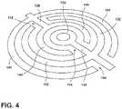
- FIG. 4is a schematic perspective view of an alternative configuration of the anode and cathode elements of the RF applicator.
- FIG. 5is a schematic perspective view of a yet another alternative configuration of the anode and cathode elements of the RF applicator.
- RFradio frequency
- the RF laundry drying appliance 10includes an RF applicator 12 supplied by an RF generator 20 .
- the RF applicator 12includes an anode element 14 and a cathode element 16 coupled to the RF generator 20 which, upon the energization of the RF generator 20 , creates an e-field between the anode and cathode.
- a drying surface 22on which laundry is supported for drying, is located relative to the RF applicator 12 such that the drying surface 22 lies within the e-field.
- a Faraday cage 26encloses the drying surface 22 .
- the drying surface 22may be in the form of a supporting body 18 , such as a non-conductive bed, having an upper surface for receiving wet laundry and which forms the drying surface 22 .
- the drying surface 22is a planar surface though other surfaces may be implemented.
- a portion of the cathode element 16may substantially encompass the anode element 14 to ensure, upon energizing of the RF generator 20 , the formation of the e-field between the anode and cathode elements 14 , 16 instead of between the anode element 14 and the Faraday cage 26 .
- the Faraday cage 26may be a conductive material or a mesh of conductive material forming an enclosure that heavily attenuates or blocks transmission of radio waves of the e-field into or out of the enclosed volume.
- the enclosure of the Faraday cage 26may be formed as the volume sealed off by a rectangular cuboid.
- the six rectangular faces of the cuboidmay be formed as the four rigid walls 29 , 31 , 33 , 35 lining the RF dryer 10 , a bottom surface (not shown) and a top surface that is formed in the lid 27 of the RF dryer when the lid is in the closed position.
- Other geometrical configurations for the enclosureincluding, but not limited to, any convex polyhedron may be implemented and the example shown in FIG. 1 should not be considered limiting.
- FIG. 2shows a region designated as II in FIG. 1 of the drying surface where the anode and cathode elements are proximal to the Faraday cage.
- the space between the cathode element 16 and the Faraday cage 26may be quantified both horizontally and vertically as the shortest distance between the cathode element 16 and the nearest face of the Faraday cage 26 in a respective plane. For example in FIG.
- the shortest horizontal distance B from the cathode element 16 and the nearest of the conductive wall elements of the Faraday cage shown as 35 in FIG. 2due to the horizontally configured RF applicator 12 in the planar drying surface 22 , the shortest vertical distance A for any element of the RF applicator 12 is the distance along the normal vector of the drying surface 22 from the RF applicator 12 to the closer of the lid 27 when closed or the bottom surface (not shown) of the RF dryer 10 .
- the anode element 14 and the cathode element 16may then be configured such that the spacing C between the anode and cathode elements 14 , 16 is less than either the horizontal or vertical spacing A, B from the cathode element 16 . In this way, the anode element 14 is spaced closer to the cathode element 16 than to the Faraday cage 26 . Also, the planar drying surface 22 may be vertically spaced from the Faraday cage 26 .
- the anode element 14may be electrically shielded from the Faraday cage 26 with at least a portion of the cathode element 16 .
- the anode element 14 and the cathode element 16each consist of a plurality of digits interdigitally arranged.
- the anode element 14may further include at least one anode terminal 50 and a linear tree structure having a trunk 30 from which extends a first plurality of digits 32 and a second plurality of digits 34 .
- the first and second plurality of digits 32 , 34may extend from opposite sides of the trunk 30 perpendicular to the length of the trunk 30 .
- each member of the first plurality of digits 32has a one-to-one corresponding member of the second plurality of digits 34 that is coupled to the trunk 30 at the same location as the corresponding member of the second plurality of digits 34 .
- the cathode element 16may further include at least one terminal 52 , a first comb element 36 having a first trunk 38 from which extend a first plurality of digits 40 and a second comb element 42 having a second trunk 44 from which extend a second plurality of digits 46 .
- the anode and cathode elements 14 , 16may be fixedly mounted to a supporting body 18 in such a way as to interdigitally arrange the first plurality of digits 32 of the anode element 14 and the first plurality of digits 40 of the first comb element 36 of the cathode element 16 .
- the anode and cathode elements 14 , 16may be fixedly mounted to the supporting body 18 in such a way as to interdigitally arrange the second plurality of digits 34 of the anode element 14 and the second plurality of digits 46 of the second comb element 42 of the cathode 16 .
- Each of the conductive anode and cathode elements 14 , 16remain at least partially spaced from each other by a separating gap, or by non-conductive segments.
- the supporting body 18may be made of any suitable low loss, fire retardant materials, or at least one layer of insulating materials that isolates the conductive anode and cathode elements 14 , 16 and may also be formed with a series of perforations to allow for airflow through the anode and cathode elements.
- the supporting body 18may also provide a rigid structure for the RF laundry dryer 10 , or may be further supported by secondary structural elements, such as a frame or truss system.
- the anode and cathode elements 14 , 16may be fixedly mounted to the supporting body 18 by, for example, adhesion, fastener connections, or laminated layers. Alternative mounting techniques may be employed.
- the anode and cathode elements 14 , 16are preferably arranged in a coplanar configuration.
- the first trunk element 38 of the cathode element 16 and the second trunk element 44 of the cathode element 16will be in physical connection by way of a third interconnecting trunk element 48 that effectively wraps the first and second comb elements 36 , 42 of the cathode element 16 around the anode element 14 .
- the anode element 14has multiple digits 32 , 34 and the cathode element 16 encompasses the multiple digits 32 , 34 of the anode element 14 .
- the cathode trunk elements 38 , 44 , 48 and the digits 41 , 47 proximal to the anode terminal 50encompass the anode digits 32 , 34 .
- at least one of the digits of the cathode 16encompasses the anode digits 32 , 34 .
- the cathode element 16has multiple digits 40 , 46 with at least some of the anode digits 32 , 34 and cathode digits 40 , 46 being interdigitated.
- the gap between the digits 41 , 47 proximal to the anode terminal 50form a space 66 in the cathode element 16 .
- the trunk 30 of the anode element 14 from which the anode digits 32 , 34 branchmay pass through the space 66 in the cathode to connect to the terminal 50 .
- the cathode element 14may have a cathode terminal 52 , 53 electrically coupled to ground 54 .
- the RF applicator 12may be configured to generate an e-field within the radio frequency spectrum between the anode 14 and cathode 16 elements.
- the anode element 14 of the RF applicator 12may be electrically coupled to an RF generator 20 and an impedance matching circuit 21 by a terminal 50 on the anode element 14 .
- the cathode element 16 of the RF applicatormay be electrically coupled to the RF generator 20 and an impedance matching circuit 21 by one or more terminals 52 , 53 , 55 of the cathode element 16 .
- the cathode terminals 52 , 53 , 55 and their connection to the RF generator 20 and impedance matching circuit 21may be additionally connected to an electrical ground 54 .
- the RF generator 20may apply an RF signal of a desired power level and frequency to energize the RF applicator 12 by supplying the RF signal to the portion of the anode passing through the gap in the cathode element 16 .
- One such example of an RF signal generated by the RF applicator 12may be 13.56 MHz.
- the radio frequency 13.56 MHzis one frequency in the band of frequencies between 13.553 MHz and 13.567 MHz, which is often referred to as the 13.56 MHz band.
- the band of frequencies between 13.553 MHz and 13.567 MHzis one of several bands that make up the industrial, scientific and medical (ISM) radio bands.
- ISMindustrial, scientific and medical
- the impedance matching circuit 21by electrically coupling the RF generator 20 and the RF applicator 12 to each other, may provide a circuit for automatically adjusting the input impedance of the electrical load to maximize power transfer from the RF generator 20 to the RF applicator 12 , where the electrical load is substantially determined by the wet textiles and the anode and cathode elements 14 , 16 .
- impedance matching circuits for RF applicationsincluding L-type, Pi-type, and T-type networks of which any may be implemented without limitation in an embodiment of the invention.
- the aforementioned structure of the RF laundry dryer 10operates by creating a capacitive coupling between the pluralities of digits 32 , 40 and 34 , 46 of the anode element 14 and the cathode element 16 , at least partially spaced from each other.
- wet textiles to be driedmay be placed on the drying surface 22 .
- the RF applicator 12may be continuously or intermittently energized to generate an e-field between the capacitive coupling of the anode and cathode digits which interacts with liquid in the textiles.
- the liquid residing within the e-fieldwill be dielectrically heated to effect a drying of the laundry.
- the impedance of the electrical loadthat is the impedance of the laundry and the RF applicator 12
- the impedance matching circuit 21may adjust the impedance of the electrical load to match the impedance of the RF generator 20 which typically holds at a steady value such as 50 Ohms.
- impedance matchingmay provide efficient transfer of power from the RF generator 20 to the RF applicator 12 .
- the e-fieldmust be formed between the anode and cathode elements 14 , 16 .
- the anode element 14should be shielded from the Faraday cage 26 to prevent unwanted electromagnetic leakage where some amount of the e-field is formed between the anode element 14 and the Faraday cage 26 .
- FIG. 4illustrates an alternative configuration of the anode and cathode elements 114 , 116 of the RF applicator 12 .
- the alternative configuration of anode and cathode elements 114 , 116may be similar to the anode and cathode elements 14 , 16 described above; therefore, like parts will be identified with like numerals beginning with 100 , with it being understood that the description of the like parts applies to the alternative configuration of anode and cathode elements, unless otherwise noted.
- the anode element 114is a circular tree structure where the digits 132 follow an arcuate path. As shown in FIG. 4 , the arcuate path is substantially circular though other paths such as elliptical may be implemented.
- the trunk 130 of the anode element 114may pass through a space 166 formed at the gap of cathode digits 141 .
- the interior digit 134 of the anode element 114may be formed as a substantially complete circle or ellipse.
- the space 166 formed at the gap of cathode digits 141may be completely eliminated as shown in FIG. 5 .
- the circular tree structure of the anode elementmay be completely enclosed by one or more digits of the cathode element 116 .
- Cathode and anode connections 210 , 212 respectively,may be provided along any of the digits of cathode and anode elements 116 , 114 .
- the cathode connection 210lies along the outer digit 141 and the anode connection 212 lies along the outer digit 132 at the antipode of the cathode connection 210 .
- the arcuate path of the anode and cathode elementsis substantially circular though other paths such as elliptical may be implemented. Other arrangements of the digits, trunk elements and terminals of the anode may be implemented.
- the digits of either the first plurality or second plurality of digits 32 , 34may not be perpendicular to the trunk element 30 .
- the digits of either the first plurality or the second plurality of digits 32 , 34may not intersect the trunk element 30 at the same angle or location.
- Many alternative configurationsmay be implemented to form the plurality of digits, the trunk elements and the interconnections between the trunk elements and the digits of the anode and cathode elements.
- one embodiment of the inventioncontemplates different geometric shapes for the textile treating appliance 10 , such as substantially longer, rectangular appliance 10 where the anode and cathode elements 14 , 16 are elongated along the length of the RF laundry dryer 10 , or the longer appliance 10 includes a plurality of anode and cathode element 14 , 16 sets.
- the design of the anode and cathodemay be controlled to allow for individual energizing of particular RF applicators in a single or multi-applicator embodiment.
- the effect of individual energization of particular RF applicatorsresults in avoiding anode/cathode pairs that would result in no additional material drying (if energized), reducing the unwanted impedance of additional anode/cathode pairs and electromagnetic fields, and an overall reduction to energy costs of a drying cycle of operation due to increased efficiencies.
- allowing for higher power on a particular RF applicator with wet material while reducing power on an RF applicator with drier materialmay result in a reduction of plate voltage and, consequently, a lower chance of arcing for an RF applicator.
- microwave frequenciesare typically applied for cooking food items.
- their high frequency and resulting greater dielectric heating effectmake microwave frequencies undesirable for drying laundry articles.
- Radio frequencies and their corresponding lower dielectric heating effectare typically used for drying of textiles.
- the RF applicator 12induces a controlled electromagnetic field between the anode and cathode elements 14 , 16 .
- Stray-field or through-field electromagnetic heatingthat is, dielectric heating by placing wet articles near or between energized applicator elements, provides a relatively deterministic application of power as opposed to conventional microwave heating technologies where the microwave energy is randomly distributed (by way of a stirrer and/or rotation of the load). Consequently, conventional microwave technologies may result in thermal runaway effects that are not easily mitigated when applied to certain loads (such as metal zippers, etc).
- a microwaveacts as a sprinkler while the above-described RF applicator 12 is a wave pool. It is understood that the differences between microwave ovens and RF dryers arise from the differences between the implementation structures of applicator vs. magnetron/waveguide, which renders much of the microwave solutions inapplicable for RF dryers.
Landscapes
- Engineering & Computer Science (AREA)
- Life Sciences & Earth Sciences (AREA)
- Microbiology (AREA)
- Electromagnetism (AREA)
- Physics & Mathematics (AREA)
- Textile Engineering (AREA)
- Biomedical Technology (AREA)
- Mechanical Engineering (AREA)
- General Engineering & Computer Science (AREA)
- Molecular Biology (AREA)
- Biotechnology (AREA)
- Health & Medical Sciences (AREA)
- Drying Of Solid Materials (AREA)
- Detail Structures Of Washing Machines And Dryers (AREA)
Abstract
Description
Claims (20)
Priority Applications (1)
| Application Number | Priority Date | Filing Date | Title |
|---|---|---|---|
| US17/077,058US11459696B2 (en) | 2013-08-23 | 2020-10-22 | Appliance for drying articles |
Applications Claiming Priority (3)
| Application Number | Priority Date | Filing Date | Title |
|---|---|---|---|
| US13/974,092US9784499B2 (en) | 2013-08-23 | 2013-08-23 | Appliance for drying articles |
| US15/685,490US10837702B2 (en) | 2013-08-23 | 2017-08-24 | Appliance for drying articles |
| US17/077,058US11459696B2 (en) | 2013-08-23 | 2020-10-22 | Appliance for drying articles |
Related Parent Applications (1)
| Application Number | Title | Priority Date | Filing Date |
|---|---|---|---|
| US15/685,490ContinuationUS10837702B2 (en) | 2013-08-23 | 2017-08-24 | Appliance for drying articles |
Publications (2)
| Publication Number | Publication Date |
|---|---|
| US20210041167A1 US20210041167A1 (en) | 2021-02-11 |
| US11459696B2true US11459696B2 (en) | 2022-10-04 |
Family
ID=51421808
Family Applications (3)
| Application Number | Title | Priority Date | Filing Date |
|---|---|---|---|
| US13/974,092Active2034-11-27US9784499B2 (en) | 2013-08-23 | 2013-08-23 | Appliance for drying articles |
| US15/685,490Expired - Fee RelatedUS10837702B2 (en) | 2013-08-23 | 2017-08-24 | Appliance for drying articles |
| US17/077,058ActiveUS11459696B2 (en) | 2013-08-23 | 2020-10-22 | Appliance for drying articles |
Family Applications Before (2)
| Application Number | Title | Priority Date | Filing Date |
|---|---|---|---|
| US13/974,092Active2034-11-27US9784499B2 (en) | 2013-08-23 | 2013-08-23 | Appliance for drying articles |
| US15/685,490Expired - Fee RelatedUS10837702B2 (en) | 2013-08-23 | 2017-08-24 | Appliance for drying articles |
Country Status (3)
| Country | Link |
|---|---|
| US (3) | US9784499B2 (en) |
| EP (1) | EP2844033B1 (en) |
| BR (1) | BR102014020758A2 (en) |
Families Citing this family (13)
| Publication number | Priority date | Publication date | Assignee | Title |
|---|---|---|---|---|
| US9200402B2 (en) | 2011-05-20 | 2015-12-01 | Cool Dry, Inc. | Dielectric dryer drum |
| US9541330B2 (en) | 2013-07-17 | 2017-01-10 | Whirlpool Corporation | Method for drying articles |
| US20150047218A1 (en)* | 2013-08-14 | 2015-02-19 | Whirlpool Corporation | Appliance for drying articles |
| US9784499B2 (en) | 2013-08-23 | 2017-10-10 | Whirlpool Corporation | Appliance for drying articles |
| US9410282B2 (en) | 2013-10-02 | 2016-08-09 | Whirlpool Corporation | Method and apparatus for drying articles |
| US9645182B2 (en) | 2013-10-16 | 2017-05-09 | Whirlpool Corporation | Method and apparatus for detecting an energized E-field |
| US9546817B2 (en) | 2013-12-09 | 2017-01-17 | Whirlpool Corporation | Method for drying articles |
| US9447537B2 (en) | 2014-11-12 | 2016-09-20 | Cool Dry, Inc. | Fixed radial anode drum dryer |
| US9605899B2 (en) | 2015-03-23 | 2017-03-28 | Whirlpool Corporation | Apparatus for drying articles |
| US10450693B2 (en) | 2015-05-08 | 2019-10-22 | Samsung Electronics Co., Ltd. | Dryer and control method thereof |
| KR102591759B1 (en)* | 2015-05-08 | 2023-10-23 | 삼성전자주식회사 | Dryer and control method thereof |
| US10487443B1 (en) | 2015-10-30 | 2019-11-26 | Cool Dry, Inc. | Hybrid RF/conventional clothes dryer |
| KR102747180B1 (en)* | 2016-12-08 | 2024-12-27 | 삼성전자주식회사 | Clothes dryer |
Citations (147)
| Publication number | Priority date | Publication date | Assignee | Title |
|---|---|---|---|---|
| US1503224A (en) | 1921-03-28 | 1924-07-29 | Miehle Printing Press & Mfg | Portable antioffset device |
| US1871269A (en) | 1929-09-25 | 1932-08-09 | Western Electric Co | Method of drying materials |
| US2112418A (en) | 1935-12-31 | 1938-03-29 | United Shoe Machinery Corp | Electrical drying |
| US2212522A (en) | 1937-12-17 | 1940-08-27 | United Shoe Machinery Corp | Use of a stray electrostatic field for drying leather and the like |
| US2226871A (en) | 1938-04-09 | 1940-12-31 | Hall Printing Co W F | Apparatus for drying |
| US2228136A (en) | 1940-03-01 | 1941-01-07 | United Shoe Machinery Corp | Sole attaching utilizing stray electrostatic field |
| US2231457A (en) | 1936-08-03 | 1941-02-11 | John L Stephen | Electrical apparatus |
| US2276996A (en) | 1940-11-30 | 1942-03-17 | A J Ginsberg | Non-radio-interfering therapeutic apparatus |
| US2373374A (en) | 1941-12-27 | 1945-04-10 | Rca Corp | Cellulosic material |
| GB601855A (en) | 1945-10-09 | 1948-05-13 | Dennis Illingworth Lawson | Applicator for radio frequency dielectric heating |
| US2449317A (en) | 1944-04-18 | 1948-09-14 | Compo Shoe Machinery Corp | Electrostatic pressing apparatus |
| US2464403A (en)* | 1945-08-30 | 1949-03-15 | Rca Corp | Apparatus for heating dielectric materials electronically |
| US2473251A (en) | 1945-05-29 | 1949-06-14 | Gen Electric | High-frequency dielectric heating apparatus |
| US2492187A (en) | 1945-01-05 | 1949-12-27 | Ralph A Rusca | Method and apparatus for electrical heating |
| US2512311A (en) | 1948-09-01 | 1950-06-20 | Gen Electric | High-frequency heating apparatus |
| US2511839A (en) | 1950-06-20 | Method and apparatus for drying | ||
| US2542589A (en)* | 1946-05-16 | 1951-02-20 | Induction Heating Corp | Electrode structure and method for dielectric heating |
| US2582806A (en) | 1947-03-18 | 1952-01-15 | American Enka Corp | Drying of hollow yarn bodies |
| US2642000A (en)* | 1944-11-29 | 1953-06-16 | Hoe & Co R | Ink drying equipment for web printing machines |
| US2656839A (en) | 1950-02-14 | 1953-10-27 | Clarence B Howard | Electrotherapeutic oscillator |
| US2740756A (en) | 1951-04-19 | 1956-04-03 | Albert G Thomas | Electrical drying system |
| US2773162A (en) | 1954-01-14 | 1956-12-04 | Boeing Co | Anti-icing of windows by dielectric heating |
| US3089327A (en) | 1951-09-07 | 1963-05-14 | Murray Corp | Apparatus for the complete laundering of fabrics |
| US3161480A (en) | 1960-09-12 | 1964-12-15 | Svenska Sockerfabriks Ab | Dielectrically heated drying apparatus through which the articles to be dried are continuously advanced |
| US3184637A (en) | 1961-12-13 | 1965-05-18 | Decca Ltd | Lamp monitoring apparatus |
| US3316380A (en) | 1964-04-30 | 1967-04-25 | Gen Motors Corp | Energy distribution detector for microwave oven |
| US3329796A (en)* | 1966-07-28 | 1967-07-04 | Radio Frequency Company Inc | Radio frequency apparatus |
| US3355812A (en) | 1965-08-04 | 1967-12-05 | Fitchburg Paper | Drying by high frequency electric field |
| US3364294A (en) | 1965-09-20 | 1968-01-16 | Monsanto Co | Filament orientation process |
| US3404466A (en) | 1967-06-28 | 1968-10-08 | Gen Electric | Electronic dryer control |
| US3426439A (en) | 1967-02-16 | 1969-02-11 | Houston Fearless Corp | Microwave drying system |
| US3439431A (en) | 1967-12-15 | 1969-04-22 | Gen Electric | Microwave dryer control circuit |
| US3537185A (en) | 1968-10-21 | 1970-11-03 | Ingram Plywoods Inc | Dielectric heating apparatus |
| US3543408A (en) | 1968-10-21 | 1970-12-01 | Robert R Candor | Liquid removing apparatus and method |
| US3599342A (en) | 1969-03-03 | 1971-08-17 | Maytag Co | Dryer control |
| US3601571A (en) | 1969-11-12 | 1971-08-24 | Park Ohio Industries Inc | Induction heating device with a controlled feeding mechanism |
| GB1255292A (en) | 1970-02-04 | 1971-12-01 | Marconi Co Ltd | Improvements in or relating to piezoelectric transducers |
| US3652816A (en) | 1970-04-13 | 1972-03-28 | Litton Business Systems Inc | Self cleaning dielectric heater |
| US3701875A (en) | 1969-06-30 | 1972-10-31 | Intertherm Ltd | H. f. heating apparatus |
| US3754336A (en) | 1971-08-10 | 1973-08-28 | E Feild | Vehicle drying apparatus |
| US3878619A (en) | 1971-10-25 | 1975-04-22 | Electricity Council | Drying of wool slivers |
| US3953701A (en) | 1975-03-24 | 1976-04-27 | Radio Frequency Co., Inc. | Radio frequency heating and ventilating electrode system |
| US3969225A (en) | 1974-04-04 | 1976-07-13 | I. Jordan Kunik | Differential separation of particulates by combined electro-static and radio frequency means |
| US4014732A (en) | 1974-06-01 | 1977-03-29 | Firma Mohndruck, Reinhard Mohn Ohg | Device for drying and setting the adhesive on backs of books |
| US4028518A (en) | 1974-06-18 | 1977-06-07 | L'oreal | Device for superficially heating an adjacent body |
| US4119826A (en) | 1977-04-04 | 1978-10-10 | Champion International Corporation | Dielectric heat generator |
| GB2019543A (en) | 1978-04-19 | 1979-10-31 | Siemens Ag | Drying by Electricity |
| US4197851A (en) | 1977-04-14 | 1980-04-15 | Fellus Victor M | Apparatus for emitting high-frequency electromagnetic waves |
| US4296299A (en) | 1979-12-31 | 1981-10-20 | General Electric Company | Apparatus for thawing frozen food in a refrigeration appliance |
| US4296298A (en)* | 1978-06-12 | 1981-10-20 | Raytheon Company | Dielectric cooking apparatus |
| US4334136A (en) | 1979-10-01 | 1982-06-08 | Douglas P. Mahan | Microwave treating mechanism |
| US4365622A (en) | 1980-09-11 | 1982-12-28 | Donald L. Morton & Associates | Multiple plate resonant electrode |
| US4409541A (en) | 1981-03-19 | 1983-10-11 | Ppg Industries, Inc. | Method of and apparatus for determining continuity of an electrical conductor |
| US4471537A (en) | 1982-01-18 | 1984-09-18 | Indesit Industria Elettrodomestici Italiana S.P.A. | Dryer apparatus having an improved air circulation |
| US4499818A (en) | 1982-09-30 | 1985-02-19 | Restaurant Technology, Inc. | Method and apparatus for holding freshly prepared fried food products |
| US4523387A (en) | 1983-12-08 | 1985-06-18 | Mahan Douglas P | Microwave treating mechanism |
| US4529855A (en) | 1982-04-12 | 1985-07-16 | Henry Fleck | Microwave radiation detector |
| US4625432A (en) | 1983-11-30 | 1986-12-02 | Hans Baltes | Apparatus and method for drying and sterilizing fabrics |
| US4638571A (en) | 1986-04-02 | 1987-01-27 | Cook William A | Radio frequency nozzle bar dryer |
| US4692581A (en) | 1985-03-12 | 1987-09-08 | Ngk Insulators, Ltd. | Condensation resistant electrode for use in a dielectric heating apparatus |
| EP0269358A2 (en) | 1986-11-25 | 1988-06-01 | PETRIE & McNAUGHT LIMITED | Drying or baking apparatus |
| US4845329A (en) | 1988-11-21 | 1989-07-04 | General Motors Corporation | Moisture removal from visual glass surfaces by dielectric heating |
| US4918290A (en)* | 1985-10-28 | 1990-04-17 | Demars Robert A | Portable towel heating device |
| US4949477A (en) | 1988-06-08 | 1990-08-21 | Passat Maschinenbau Gmbh | Control system with valve flaps for a drier |
| US5064979A (en) | 1990-08-07 | 1991-11-12 | W. R. Grace & Co.-Conn. | Microwave air float bar for drying a traveling web |
| US5152075A (en) | 1991-09-27 | 1992-10-06 | Bonar George D | Drying of clothes by electrolysis |
| JPH04307095A (en) | 1991-04-03 | 1992-10-29 | Matsushita Electric Ind Co Ltd | Drying apparatus |
| US5197202A (en) | 1990-09-26 | 1993-03-30 | Ppg Industries, Inc. | Method and apparatus for drying and curing a coated strand |
| US5282321A (en) | 1991-06-05 | 1994-02-01 | Huettlin Herbert | Fluidized bed apparatus for treating particulate materials |
| US5303484A (en) | 1992-04-09 | 1994-04-19 | Thermo Electron Web Systems, Inc. | Compact convective web dryer |
| US5394619A (en) | 1994-03-14 | 1995-03-07 | Kaplan; Bruce E. | Portable clothes dryer and room humidifier |
| US5495250A (en) | 1993-11-01 | 1996-02-27 | Motorola, Inc. | Battery-powered RF tags and apparatus for manufacturing the same |
| US5553532A (en) | 1993-10-12 | 1996-09-10 | Centro De Investigacion Y De Estudios Avanzados Del I.P.N. | Apparatus for cooking food products using very low and low frequency radio waves |
| US5659972A (en) | 1995-10-06 | 1997-08-26 | Avery Dennison Corporation | Apparatus and method for drying or curing web materials and coatings |
| US5692317A (en) | 1995-07-14 | 1997-12-02 | Marlegreen Holding S.A. | Method and facility for dehydrating plants particularly, for dehydrating forage |
| US5819431A (en) | 1997-01-10 | 1998-10-13 | Lancer; Harold | Foot dryer apparatus and method of drying feet |
| US5838111A (en) | 1996-02-27 | 1998-11-17 | Matsushita Electric Industrial Co., Ltd. | Plasma generator with antennas attached to top electrodes |
| US5853579A (en) | 1996-11-26 | 1998-12-29 | Wastech International Inc. | Treatment system |
| US5886081A (en) | 1997-08-05 | 1999-03-23 | Rockwell Science Center, Inc. | Efficient dielectrically heatable compound and method |
| US5943705A (en) | 1998-03-05 | 1999-08-31 | Sink; Michael D. | Athletic equipment attachment strap |
| US5983520A (en) | 1997-10-08 | 1999-11-16 | Lg Electronics Inc. | Microwave dryer for washing machine |
| US6124584A (en) | 1999-06-18 | 2000-09-26 | Heatwave Drying Systems Inc | Moisture measurement control of wood in radio frequency dielectric processes |
| US6189231B1 (en) | 1999-07-15 | 2001-02-20 | Harold Lancer | Foot dryer apparatus |
| US6263591B1 (en)* | 2000-01-25 | 2001-07-24 | Victor M. La Porte | Sports equipment drying container |
| US6303166B1 (en) | 1998-04-21 | 2001-10-16 | The State Of Oregon Acting By And Through The State Board Of Higher Education On Behalf Of Oregon State University | Capacative dielectric heating system |
| US6367165B1 (en) | 1999-02-03 | 2002-04-09 | Huettlin Herbert | Device for treating particulate product |
| US20020047009A1 (en) | 1998-04-21 | 2002-04-25 | The State Of Or Acting By And Through The State Board Of Higher Edu. On Behalf Of Or State Univ. | Variable frequency automated capacitive radio frequency (RF) dielectric heating system |
| US6421931B1 (en) | 2001-05-08 | 2002-07-23 | Daniel R Chapman | Method and apparatus for drying iron ore pellets |
| US6531880B1 (en) | 2000-07-03 | 2003-03-11 | American Electric Power Company, Inc. | Non-invasive cable tester |
| US6546109B1 (en) | 2000-01-03 | 2003-04-08 | Louis Thomas Gnecco | Electromagnetically shielded hearing aids |
| US20030199251A1 (en)* | 2002-03-18 | 2003-10-23 | Gorbold Timothy D. | Electrode apparatus for stray field radio frequency heating |
| US6649879B1 (en) | 1999-09-15 | 2003-11-18 | Rational Aktiengesellschaft | Method and device for homogenizing the energy supply to products to be cooked |
| US20040149734A1 (en) | 1998-06-15 | 2004-08-05 | Victor Petrenko | Ice modification removal and prevention |
| US20050120715A1 (en) | 1997-12-23 | 2005-06-09 | Christion School Of Technology Charitable Foundation Trust | Heat energy recapture and recycle and its new applications |
| US20050278972A1 (en) | 2004-06-18 | 2005-12-22 | Maruca Robert E | Low temperature clothes dryer |
| US20050286914A1 (en) | 2004-06-28 | 2005-12-29 | Sharp Kabushiki Kaisha | Image forming apparatus |
| US20060097726A1 (en) | 2001-03-20 | 2006-05-11 | Integrated Power Components, Inc. | Detection of malfunctioning bulbs in decorative light strings |
| US20060289526A1 (en) | 2003-04-25 | 2006-12-28 | Matsushita Electric Industrial Co., Ltd. | High-frequency heating device and method for controlling same |
| EP1753265A1 (en) | 2005-08-08 | 2007-02-14 | Falmer Investments Limited | Radio frequency textile drying machine |
| US20070113421A1 (en) | 2003-12-10 | 2007-05-24 | Hiroko Uhara | Washing and drying machine and clothes dryer |
| US20070193058A1 (en) | 2006-02-23 | 2007-08-23 | Zarembinski Thomas P | Drying cabinet and ventilation system |
| US20080134792A1 (en) | 2006-12-06 | 2008-06-12 | Electronics And Telecommunications Research Institute | Interdigitated electrode for electronic device and electronic device using the same |
| US20080256826A1 (en) | 2006-02-23 | 2008-10-23 | Zarembinski Thomas P | Drying cabinet with ventilation system |
| US7526879B2 (en) | 2005-11-04 | 2009-05-05 | Lg Electronics Inc. | Drum washing machine and clothes dryer using peltier thermoelectric module |
| US20090151193A1 (en) | 2007-08-03 | 2009-06-18 | Lg Electronics Inc. | Cloth treating apparatus |
| US20090172965A1 (en) | 2006-04-14 | 2009-07-09 | Electrolux Home Products Corporation N.V. | Household appliance |
| US20090195255A1 (en) | 2004-12-23 | 2009-08-06 | David Kalokitis | Apparatus and method for monitoring and controlling detection of stray voltage anomalies |
| WO2009106906A1 (en) | 2008-02-27 | 2009-09-03 | Budapesti Müszaki És Gazdaságtudományi Egyetem | Interdigitated electrode |
| US7619403B2 (en) | 2004-08-31 | 2009-11-17 | Niigata University | Method for electrically detecting motion of nonpolar composite molecule by utilizing nonuniform electric field |
| US20100043527A1 (en) | 2005-06-28 | 2010-02-25 | Koninklijke Philips Electronics N.V. | Ultra fine particle sensor |
| US7676953B2 (en) | 2006-12-29 | 2010-03-16 | Signature Control Systems, Inc. | Calibration and metering methods for wood kiln moisture measurement |
| US20100103095A1 (en) | 2007-09-12 | 2010-04-29 | Sony Corporation | Input apparatus, control apparatus, control system, and control method |
| US20100115785A1 (en) | 2006-02-21 | 2010-05-13 | Bora Appliances Limited | Drying apparatus and methods and accessories for use therewith |
| US20100146805A1 (en) | 2008-12-09 | 2010-06-17 | Lg Electronics Inc. | Fabric treating apparatus |
| US20110049133A1 (en) | 2008-02-15 | 2011-03-03 | E2V Technologies (UK)Limited | Rf heating of a dielectric fluid |
| US20110245900A1 (en) | 2010-04-06 | 2011-10-06 | Turner Paul F | Deep heating hyperthermia using phased arrays and patient positioning |
| US20110308101A1 (en) | 2010-06-17 | 2011-12-22 | Cool Dry LLC | High efficiency heat generator |
| WO2012001523A2 (en) | 2010-07-01 | 2012-01-05 | Goji Ltd. | Processing objects by radio frequency (rf) energy |
| US20120000087A1 (en) | 2008-12-30 | 2012-01-05 | Electrolux Home Products Corporation N.V. | Household Appliance for Drying Garments |
| US20120164022A1 (en) | 2010-12-22 | 2012-06-28 | Goji Limited | Methods and devices for processing objects by applying electromagnetic (em) energy |
| USRE43519E1 (en) | 1995-11-13 | 2012-07-17 | Acacia Patent Acquisition Corporation | Electromagnetically protected hearing aids |
| US20120247800A1 (en) | 2009-04-24 | 2012-10-04 | Applied Nanostructured Solutions, Llc | Cns-shielded wires |
| US20120291304A1 (en) | 2011-05-20 | 2012-11-22 | Cool Dry LLC | Dielectric dryer drum |
| US20130024169A1 (en) | 2006-01-10 | 2013-01-24 | Guardian Industries Corp. | Moisture sensor and/or defogger with bayesian improvements, and related methods |
| US20130119055A1 (en) | 2011-11-16 | 2013-05-16 | Cool Dry LLC | Ionic adder dryer technology |
| US8499472B2 (en) | 2006-03-17 | 2013-08-06 | Electrolux Home Products Corporation N.V. | Household appliance for washing and/or drying clothes |
| US20130201068A1 (en) | 2010-04-11 | 2013-08-08 | Broadcom Corporation | Programmable antenna having a programmable substrate |
| US20130207674A1 (en) | 2010-07-07 | 2013-08-15 | Robert Bosch Gmbh | Detecting a Dielectric Article |
| US20130271811A1 (en) | 2010-12-15 | 2013-10-17 | Switch Materials, Inc. | Variable transmittance optical filter with substantially co-planar electrode system |
| US20130316051A1 (en) | 2012-05-25 | 2013-11-28 | Top B.V. | Apparatus and process for heat treating a packaged food product |
| US20140159716A1 (en) | 2012-12-10 | 2014-06-12 | Electric Power Research Institute | Portable magnetic, electric and radio frequency field monitoring apparatus and method |
| US8789599B2 (en) | 2010-09-20 | 2014-07-29 | Harris Corporation | Radio frequency heat applicator for increased heavy oil recovery |
| US20140325865A1 (en) | 2011-05-20 | 2014-11-06 | Cool Dry LLC | Dielectric dryer drum |
| EP2827087A1 (en) | 2013-07-17 | 2015-01-21 | Whirlpool Corporation | Method for drying articles |
| US20150047218A1 (en) | 2013-08-14 | 2015-02-19 | Whirlpool Corporation | Appliance for drying articles |
| EP2840340A2 (en) | 2013-08-20 | 2015-02-25 | Whirlpool Corporation | Method for drying articles |
| US20150052775A1 (en) | 2013-08-23 | 2015-02-26 | Whirlpool Corporation | Appliance for drying articles |
| US20150089829A1 (en) | 2013-10-02 | 2015-04-02 | Whirlpool Corporation | Method and apparatus for drying articles |
| US20150101207A1 (en) | 2013-10-14 | 2015-04-16 | Whirlpool Corporation | Method and apparatus for drying articles |
| US20150102801A1 (en) | 2013-10-16 | 2015-04-16 | Whirlpool Corporation | Method and apparatus for detecting an energized e-field |
| US20150159949A1 (en) | 2013-12-09 | 2015-06-11 | Whirlpool Corporation | Method for drying articles |
| US20150187971A1 (en) | 2012-08-16 | 2015-07-02 | Airbus Defence and Space GmbH | Laser power converter |
| US20150377795A1 (en) | 2013-03-11 | 2015-12-31 | Kla-Tencor Corporation | Defect detection using surface enhanced electric field |
| US9447537B2 (en) | 2014-11-12 | 2016-09-20 | Cool Dry, Inc. | Fixed radial anode drum dryer |
| EP3073008A1 (en) | 2015-03-23 | 2016-09-28 | Whirlpool Corporation | Apparatus for drying articles |
| US20190062914A1 (en) | 2017-08-24 | 2019-02-28 | Forge Nano, Inc. | Manufacturing processes to synthesize, functionalize, surface treat and/or encapsulate powders, and applications thereof |
| US20210078013A1 (en) | 2017-05-30 | 2021-03-18 | Li-Cycle Corp. | Process, apparatus, and system for recovering materials from batteries |
- 2013
- 2013-08-23USUS13/974,092patent/US9784499B2/enactiveActive
- 2014
- 2014-07-29EPEP14179021.2Apatent/EP2844033B1/ennot_activeNot-in-force
- 2014-08-22BRBR102014020758Apatent/BR102014020758A2/ennot_activeIP Right Cessation
- 2017
- 2017-08-24USUS15/685,490patent/US10837702B2/ennot_activeExpired - Fee Related
- 2020
- 2020-10-22USUS17/077,058patent/US11459696B2/enactiveActive
Patent Citations (179)
| Publication number | Priority date | Publication date | Assignee | Title |
|---|---|---|---|---|
| US2511839A (en) | 1950-06-20 | Method and apparatus for drying | ||
| US1503224A (en) | 1921-03-28 | 1924-07-29 | Miehle Printing Press & Mfg | Portable antioffset device |
| US1871269A (en) | 1929-09-25 | 1932-08-09 | Western Electric Co | Method of drying materials |
| US2112418A (en) | 1935-12-31 | 1938-03-29 | United Shoe Machinery Corp | Electrical drying |
| US2231457A (en) | 1936-08-03 | 1941-02-11 | John L Stephen | Electrical apparatus |
| US2212522A (en) | 1937-12-17 | 1940-08-27 | United Shoe Machinery Corp | Use of a stray electrostatic field for drying leather and the like |
| US2226871A (en) | 1938-04-09 | 1940-12-31 | Hall Printing Co W F | Apparatus for drying |
| US2228136A (en) | 1940-03-01 | 1941-01-07 | United Shoe Machinery Corp | Sole attaching utilizing stray electrostatic field |
| US2276996A (en) | 1940-11-30 | 1942-03-17 | A J Ginsberg | Non-radio-interfering therapeutic apparatus |
| US2373374A (en) | 1941-12-27 | 1945-04-10 | Rca Corp | Cellulosic material |
| US2449317A (en) | 1944-04-18 | 1948-09-14 | Compo Shoe Machinery Corp | Electrostatic pressing apparatus |
| US2642000A (en)* | 1944-11-29 | 1953-06-16 | Hoe & Co R | Ink drying equipment for web printing machines |
| US2492187A (en) | 1945-01-05 | 1949-12-27 | Ralph A Rusca | Method and apparatus for electrical heating |
| US2473251A (en) | 1945-05-29 | 1949-06-14 | Gen Electric | High-frequency dielectric heating apparatus |
| US2464403A (en)* | 1945-08-30 | 1949-03-15 | Rca Corp | Apparatus for heating dielectric materials electronically |
| GB601855A (en) | 1945-10-09 | 1948-05-13 | Dennis Illingworth Lawson | Applicator for radio frequency dielectric heating |
| US2542589A (en)* | 1946-05-16 | 1951-02-20 | Induction Heating Corp | Electrode structure and method for dielectric heating |
| US2582806A (en) | 1947-03-18 | 1952-01-15 | American Enka Corp | Drying of hollow yarn bodies |
| US2512311A (en) | 1948-09-01 | 1950-06-20 | Gen Electric | High-frequency heating apparatus |
| US2656839A (en) | 1950-02-14 | 1953-10-27 | Clarence B Howard | Electrotherapeutic oscillator |
| US2740756A (en) | 1951-04-19 | 1956-04-03 | Albert G Thomas | Electrical drying system |
| US3089327A (en) | 1951-09-07 | 1963-05-14 | Murray Corp | Apparatus for the complete laundering of fabrics |
| US2773162A (en) | 1954-01-14 | 1956-12-04 | Boeing Co | Anti-icing of windows by dielectric heating |
| US3161480A (en) | 1960-09-12 | 1964-12-15 | Svenska Sockerfabriks Ab | Dielectrically heated drying apparatus through which the articles to be dried are continuously advanced |
| US3184637A (en) | 1961-12-13 | 1965-05-18 | Decca Ltd | Lamp monitoring apparatus |
| US3316380A (en) | 1964-04-30 | 1967-04-25 | Gen Motors Corp | Energy distribution detector for microwave oven |
| US3355812A (en) | 1965-08-04 | 1967-12-05 | Fitchburg Paper | Drying by high frequency electric field |
| US3364294A (en) | 1965-09-20 | 1968-01-16 | Monsanto Co | Filament orientation process |
| US3329796A (en)* | 1966-07-28 | 1967-07-04 | Radio Frequency Company Inc | Radio frequency apparatus |
| US3426439A (en) | 1967-02-16 | 1969-02-11 | Houston Fearless Corp | Microwave drying system |
| US3404466A (en) | 1967-06-28 | 1968-10-08 | Gen Electric | Electronic dryer control |
| US3439431A (en) | 1967-12-15 | 1969-04-22 | Gen Electric | Microwave dryer control circuit |
| US3537185A (en) | 1968-10-21 | 1970-11-03 | Ingram Plywoods Inc | Dielectric heating apparatus |
| US3543408A (en) | 1968-10-21 | 1970-12-01 | Robert R Candor | Liquid removing apparatus and method |
| US3599342A (en) | 1969-03-03 | 1971-08-17 | Maytag Co | Dryer control |
| US3701875A (en) | 1969-06-30 | 1972-10-31 | Intertherm Ltd | H. f. heating apparatus |
| US3601571A (en) | 1969-11-12 | 1971-08-24 | Park Ohio Industries Inc | Induction heating device with a controlled feeding mechanism |
| GB1255292A (en) | 1970-02-04 | 1971-12-01 | Marconi Co Ltd | Improvements in or relating to piezoelectric transducers |
| US3652816A (en) | 1970-04-13 | 1972-03-28 | Litton Business Systems Inc | Self cleaning dielectric heater |
| US3754336A (en) | 1971-08-10 | 1973-08-28 | E Feild | Vehicle drying apparatus |
| US3878619A (en) | 1971-10-25 | 1975-04-22 | Electricity Council | Drying of wool slivers |
| US3969225A (en) | 1974-04-04 | 1976-07-13 | I. Jordan Kunik | Differential separation of particulates by combined electro-static and radio frequency means |
| US4014732A (en) | 1974-06-01 | 1977-03-29 | Firma Mohndruck, Reinhard Mohn Ohg | Device for drying and setting the adhesive on backs of books |
| US4028518A (en) | 1974-06-18 | 1977-06-07 | L'oreal | Device for superficially heating an adjacent body |
| US3953701A (en) | 1975-03-24 | 1976-04-27 | Radio Frequency Co., Inc. | Radio frequency heating and ventilating electrode system |
| US4119826A (en) | 1977-04-04 | 1978-10-10 | Champion International Corporation | Dielectric heat generator |
| US4197851A (en) | 1977-04-14 | 1980-04-15 | Fellus Victor M | Apparatus for emitting high-frequency electromagnetic waves |
| GB2019543A (en) | 1978-04-19 | 1979-10-31 | Siemens Ag | Drying by Electricity |
| US4296298A (en)* | 1978-06-12 | 1981-10-20 | Raytheon Company | Dielectric cooking apparatus |
| US4334136A (en) | 1979-10-01 | 1982-06-08 | Douglas P. Mahan | Microwave treating mechanism |
| US4296299A (en) | 1979-12-31 | 1981-10-20 | General Electric Company | Apparatus for thawing frozen food in a refrigeration appliance |
| US4365622A (en) | 1980-09-11 | 1982-12-28 | Donald L. Morton & Associates | Multiple plate resonant electrode |
| US4409541A (en) | 1981-03-19 | 1983-10-11 | Ppg Industries, Inc. | Method of and apparatus for determining continuity of an electrical conductor |
| US4471537A (en) | 1982-01-18 | 1984-09-18 | Indesit Industria Elettrodomestici Italiana S.P.A. | Dryer apparatus having an improved air circulation |
| US4529855A (en) | 1982-04-12 | 1985-07-16 | Henry Fleck | Microwave radiation detector |
| US4499818A (en) | 1982-09-30 | 1985-02-19 | Restaurant Technology, Inc. | Method and apparatus for holding freshly prepared fried food products |
| US4625432A (en) | 1983-11-30 | 1986-12-02 | Hans Baltes | Apparatus and method for drying and sterilizing fabrics |
| US4523387A (en) | 1983-12-08 | 1985-06-18 | Mahan Douglas P | Microwave treating mechanism |
| US4692581A (en) | 1985-03-12 | 1987-09-08 | Ngk Insulators, Ltd. | Condensation resistant electrode for use in a dielectric heating apparatus |
| US4918290A (en)* | 1985-10-28 | 1990-04-17 | Demars Robert A | Portable towel heating device |
| US4638571A (en) | 1986-04-02 | 1987-01-27 | Cook William A | Radio frequency nozzle bar dryer |
| EP0269358A2 (en) | 1986-11-25 | 1988-06-01 | PETRIE & McNAUGHT LIMITED | Drying or baking apparatus |
| US4949477A (en) | 1988-06-08 | 1990-08-21 | Passat Maschinenbau Gmbh | Control system with valve flaps for a drier |
| US4845329A (en) | 1988-11-21 | 1989-07-04 | General Motors Corporation | Moisture removal from visual glass surfaces by dielectric heating |
| US5064979A (en) | 1990-08-07 | 1991-11-12 | W. R. Grace & Co.-Conn. | Microwave air float bar for drying a traveling web |
| US5197202A (en) | 1990-09-26 | 1993-03-30 | Ppg Industries, Inc. | Method and apparatus for drying and curing a coated strand |
| JPH04307095A (en) | 1991-04-03 | 1992-10-29 | Matsushita Electric Ind Co Ltd | Drying apparatus |
| US5282321A (en) | 1991-06-05 | 1994-02-01 | Huettlin Herbert | Fluidized bed apparatus for treating particulate materials |
| US5152075A (en) | 1991-09-27 | 1992-10-06 | Bonar George D | Drying of clothes by electrolysis |
| US5303484A (en) | 1992-04-09 | 1994-04-19 | Thermo Electron Web Systems, Inc. | Compact convective web dryer |
| US5553532A (en) | 1993-10-12 | 1996-09-10 | Centro De Investigacion Y De Estudios Avanzados Del I.P.N. | Apparatus for cooking food products using very low and low frequency radio waves |
| US5495250A (en) | 1993-11-01 | 1996-02-27 | Motorola, Inc. | Battery-powered RF tags and apparatus for manufacturing the same |
| US5394619A (en) | 1994-03-14 | 1995-03-07 | Kaplan; Bruce E. | Portable clothes dryer and room humidifier |
| US5692317A (en) | 1995-07-14 | 1997-12-02 | Marlegreen Holding S.A. | Method and facility for dehydrating plants particularly, for dehydrating forage |
| US5659972A (en) | 1995-10-06 | 1997-08-26 | Avery Dennison Corporation | Apparatus and method for drying or curing web materials and coatings |
| USRE43519E1 (en) | 1995-11-13 | 2012-07-17 | Acacia Patent Acquisition Corporation | Electromagnetically protected hearing aids |
| US5838111A (en) | 1996-02-27 | 1998-11-17 | Matsushita Electric Industrial Co., Ltd. | Plasma generator with antennas attached to top electrodes |
| US5853579A (en) | 1996-11-26 | 1998-12-29 | Wastech International Inc. | Treatment system |
| US5819431A (en) | 1997-01-10 | 1998-10-13 | Lancer; Harold | Foot dryer apparatus and method of drying feet |
| US5886081A (en) | 1997-08-05 | 1999-03-23 | Rockwell Science Center, Inc. | Efficient dielectrically heatable compound and method |
| US5983520A (en) | 1997-10-08 | 1999-11-16 | Lg Electronics Inc. | Microwave dryer for washing machine |
| US20050120715A1 (en) | 1997-12-23 | 2005-06-09 | Christion School Of Technology Charitable Foundation Trust | Heat energy recapture and recycle and its new applications |
| US5943705A (en) | 1998-03-05 | 1999-08-31 | Sink; Michael D. | Athletic equipment attachment strap |
| US6303166B1 (en) | 1998-04-21 | 2001-10-16 | The State Of Oregon Acting By And Through The State Board Of Higher Education On Behalf Of Oregon State University | Capacative dielectric heating system |
| US20020047009A1 (en) | 1998-04-21 | 2002-04-25 | The State Of Or Acting By And Through The State Board Of Higher Edu. On Behalf Of Or State Univ. | Variable frequency automated capacitive radio frequency (RF) dielectric heating system |
| US7883609B2 (en) | 1998-06-15 | 2011-02-08 | The Trustees Of Dartmouth College | Ice modification removal and prevention |
| US20040149734A1 (en) | 1998-06-15 | 2004-08-05 | Victor Petrenko | Ice modification removal and prevention |
| US6367165B1 (en) | 1999-02-03 | 2002-04-09 | Huettlin Herbert | Device for treating particulate product |
| US6124584A (en) | 1999-06-18 | 2000-09-26 | Heatwave Drying Systems Inc | Moisture measurement control of wood in radio frequency dielectric processes |
| US6189231B1 (en) | 1999-07-15 | 2001-02-20 | Harold Lancer | Foot dryer apparatus |
| US6649879B1 (en) | 1999-09-15 | 2003-11-18 | Rational Aktiengesellschaft | Method and device for homogenizing the energy supply to products to be cooked |
| US6546109B1 (en) | 2000-01-03 | 2003-04-08 | Louis Thomas Gnecco | Electromagnetically shielded hearing aids |
| US6263591B1 (en)* | 2000-01-25 | 2001-07-24 | Victor M. La Porte | Sports equipment drying container |
| US6531880B1 (en) | 2000-07-03 | 2003-03-11 | American Electric Power Company, Inc. | Non-invasive cable tester |
| US20060097726A1 (en) | 2001-03-20 | 2006-05-11 | Integrated Power Components, Inc. | Detection of malfunctioning bulbs in decorative light strings |
| US6421931B1 (en) | 2001-05-08 | 2002-07-23 | Daniel R Chapman | Method and apparatus for drying iron ore pellets |
| US6812445B2 (en)* | 2002-03-18 | 2004-11-02 | Codaco, Inc. | Electrode apparatus for stray field radio frequency heating |
| US20030199251A1 (en)* | 2002-03-18 | 2003-10-23 | Gorbold Timothy D. | Electrode apparatus for stray field radio frequency heating |
| US20060289526A1 (en) | 2003-04-25 | 2006-12-28 | Matsushita Electric Industrial Co., Ltd. | High-frequency heating device and method for controlling same |
| US20070113421A1 (en) | 2003-12-10 | 2007-05-24 | Hiroko Uhara | Washing and drying machine and clothes dryer |
| US20050278972A1 (en) | 2004-06-18 | 2005-12-22 | Maruca Robert E | Low temperature clothes dryer |
| US20050286914A1 (en) | 2004-06-28 | 2005-12-29 | Sharp Kabushiki Kaisha | Image forming apparatus |
| US7619403B2 (en) | 2004-08-31 | 2009-11-17 | Niigata University | Method for electrically detecting motion of nonpolar composite molecule by utilizing nonuniform electric field |
| US20090195255A1 (en) | 2004-12-23 | 2009-08-06 | David Kalokitis | Apparatus and method for monitoring and controlling detection of stray voltage anomalies |
| US20100043527A1 (en) | 2005-06-28 | 2010-02-25 | Koninklijke Philips Electronics N.V. | Ultra fine particle sensor |
| EP1753265A1 (en) | 2005-08-08 | 2007-02-14 | Falmer Investments Limited | Radio frequency textile drying machine |
| US20070045307A1 (en) | 2005-08-08 | 2007-03-01 | Falmer Investments Ltd. | Radio frequency textile drying machine |
| US7526879B2 (en) | 2005-11-04 | 2009-05-05 | Lg Electronics Inc. | Drum washing machine and clothes dryer using peltier thermoelectric module |
| US20130024169A1 (en) | 2006-01-10 | 2013-01-24 | Guardian Industries Corp. | Moisture sensor and/or defogger with bayesian improvements, and related methods |
| US20100115785A1 (en) | 2006-02-21 | 2010-05-13 | Bora Appliances Limited | Drying apparatus and methods and accessories for use therewith |
| US8839527B2 (en) | 2006-02-21 | 2014-09-23 | Goji Limited | Drying apparatus and methods and accessories for use therewith |
| US20070193058A1 (en) | 2006-02-23 | 2007-08-23 | Zarembinski Thomas P | Drying cabinet and ventilation system |
| US20080256826A1 (en) | 2006-02-23 | 2008-10-23 | Zarembinski Thomas P | Drying cabinet with ventilation system |
| US8499472B2 (en) | 2006-03-17 | 2013-08-06 | Electrolux Home Products Corporation N.V. | Household appliance for washing and/or drying clothes |
| US20090172965A1 (en) | 2006-04-14 | 2009-07-09 | Electrolux Home Products Corporation N.V. | Household appliance |
| US20080134792A1 (en) | 2006-12-06 | 2008-06-12 | Electronics And Telecommunications Research Institute | Interdigitated electrode for electronic device and electronic device using the same |
| US7676953B2 (en) | 2006-12-29 | 2010-03-16 | Signature Control Systems, Inc. | Calibration and metering methods for wood kiln moisture measurement |
| US20090151193A1 (en) | 2007-08-03 | 2009-06-18 | Lg Electronics Inc. | Cloth treating apparatus |
| US20100103095A1 (en) | 2007-09-12 | 2010-04-29 | Sony Corporation | Input apparatus, control apparatus, control system, and control method |
| US20110049133A1 (en) | 2008-02-15 | 2011-03-03 | E2V Technologies (UK)Limited | Rf heating of a dielectric fluid |
| WO2009106906A1 (en) | 2008-02-27 | 2009-09-03 | Budapesti Müszaki És Gazdaságtudományi Egyetem | Interdigitated electrode |
| US20100146805A1 (en) | 2008-12-09 | 2010-06-17 | Lg Electronics Inc. | Fabric treating apparatus |
| US20120000087A1 (en) | 2008-12-30 | 2012-01-05 | Electrolux Home Products Corporation N.V. | Household Appliance for Drying Garments |
| US20120247800A1 (en) | 2009-04-24 | 2012-10-04 | Applied Nanostructured Solutions, Llc | Cns-shielded wires |
| US20110245900A1 (en) | 2010-04-06 | 2011-10-06 | Turner Paul F | Deep heating hyperthermia using phased arrays and patient positioning |
| US20130201068A1 (en) | 2010-04-11 | 2013-08-08 | Broadcom Corporation | Programmable antenna having a programmable substrate |
| US8826561B2 (en) | 2010-06-17 | 2014-09-09 | Cool Dry LLC | High efficiency heat generator |
| US20110308101A1 (en) | 2010-06-17 | 2011-12-22 | Cool Dry LLC | High efficiency heat generator |
| WO2012001523A2 (en) | 2010-07-01 | 2012-01-05 | Goji Ltd. | Processing objects by radio frequency (rf) energy |
| US20130207674A1 (en) | 2010-07-07 | 2013-08-15 | Robert Bosch Gmbh | Detecting a Dielectric Article |
| US8789599B2 (en) | 2010-09-20 | 2014-07-29 | Harris Corporation | Radio frequency heat applicator for increased heavy oil recovery |
| US20130271811A1 (en) | 2010-12-15 | 2013-10-17 | Switch Materials, Inc. | Variable transmittance optical filter with substantially co-planar electrode system |
| US20120164022A1 (en) | 2010-12-22 | 2012-06-28 | Goji Limited | Methods and devices for processing objects by applying electromagnetic (em) energy |
| US20120291304A1 (en) | 2011-05-20 | 2012-11-22 | Cool Dry LLC | Dielectric dryer drum |
| US20140325865A1 (en) | 2011-05-20 | 2014-11-06 | Cool Dry LLC | Dielectric dryer drum |
| US8943705B2 (en) | 2011-05-20 | 2015-02-03 | Cool Dry LLC | Dielectric dryer drum |
| US9200402B2 (en) | 2011-05-20 | 2015-12-01 | Cool Dry, Inc. | Dielectric dryer drum |
| US20130119055A1 (en) | 2011-11-16 | 2013-05-16 | Cool Dry LLC | Ionic adder dryer technology |
| US9173253B2 (en) | 2011-11-16 | 2015-10-27 | Cool Dry, Inc. | Ionic adder dryer technology |
| US20130316051A1 (en) | 2012-05-25 | 2013-11-28 | Top B.V. | Apparatus and process for heat treating a packaged food product |
| US20150187971A1 (en) | 2012-08-16 | 2015-07-02 | Airbus Defence and Space GmbH | Laser power converter |
| US20140159716A1 (en) | 2012-12-10 | 2014-06-12 | Electric Power Research Institute | Portable magnetic, electric and radio frequency field monitoring apparatus and method |
| US20150377795A1 (en) | 2013-03-11 | 2015-12-31 | Kla-Tencor Corporation | Defect detection using surface enhanced electric field |
| US20150020403A1 (en) | 2013-07-17 | 2015-01-22 | Whirlpool Corporation | Method for drying articles |
| US20190128605A1 (en) | 2013-07-17 | 2019-05-02 | Whirlpool Corporation | Method for drying articles |
| US10184718B2 (en) | 2013-07-17 | 2019-01-22 | Whirlpool Corporation | Method for drying articles |
| EP2827087A1 (en) | 2013-07-17 | 2015-01-21 | Whirlpool Corporation | Method for drying articles |
| US9541330B2 (en) | 2013-07-17 | 2017-01-10 | Whirlpool Corporation | Method for drying articles |
| US20200149812A1 (en) | 2013-08-14 | 2020-05-14 | Whirlpool Corporation | Appliance for drying articles |
| US20150047218A1 (en) | 2013-08-14 | 2015-02-19 | Whirlpool Corporation | Appliance for drying articles |
| US10533798B2 (en) | 2013-08-14 | 2020-01-14 | Whirlpool Corporation | Appliance for drying articles |
| US20180031316A1 (en) | 2013-08-14 | 2018-02-01 | Whirlpool Corporation | Appliance for drying articles |
| EP2840340A2 (en) | 2013-08-20 | 2015-02-25 | Whirlpool Corporation | Method for drying articles |
| US9194625B2 (en) | 2013-08-20 | 2015-11-24 | Whirlpool Corporation | Method for drying articles |
| US20150052775A1 (en) | 2013-08-23 | 2015-02-26 | Whirlpool Corporation | Appliance for drying articles |
| US20170350651A1 (en) | 2013-08-23 | 2017-12-07 | Whirlpool Corporation | Appliance for drying articles |
| US9784499B2 (en) | 2013-08-23 | 2017-10-10 | Whirlpool Corporation | Appliance for drying articles |
| US20190271504A1 (en) | 2013-10-02 | 2019-09-05 | Whirlpool Corporation | Method and apparatus for drying articles |
| US9540759B2 (en) | 2013-10-02 | 2017-01-10 | Whirlpool Corporation | Method and apparatus for drying articles |
| US20160281290A1 (en) | 2013-10-02 | 2016-09-29 | Whirlpool Corporation | Method and apparatus for drying articles |
| US20150089829A1 (en) | 2013-10-02 | 2015-04-02 | Whirlpool Corporation | Method and apparatus for drying articles |
| US10323881B2 (en) | 2013-10-02 | 2019-06-18 | Whirlpool Corporation | Method and apparatus for drying articles |
| US20170089639A1 (en) | 2013-10-02 | 2017-03-30 | Whirlpool Corporation | Method and apparatus for drying articles |
| US9410282B2 (en) | 2013-10-02 | 2016-08-09 | Whirlpool Corporation | Method and apparatus for drying articles |
| US9127400B2 (en) | 2013-10-14 | 2015-09-08 | Whirlpool Corporation | Method and apparatus for drying articles |
| US20150101207A1 (en) | 2013-10-14 | 2015-04-16 | Whirlpool Corporation | Method and apparatus for drying articles |
| US9645182B2 (en) | 2013-10-16 | 2017-05-09 | Whirlpool Corporation | Method and apparatus for detecting an energized E-field |
| US20150102801A1 (en) | 2013-10-16 | 2015-04-16 | Whirlpool Corporation | Method and apparatus for detecting an energized e-field |
| US9546817B2 (en) | 2013-12-09 | 2017-01-17 | Whirlpool Corporation | Method for drying articles |
| US20150159949A1 (en) | 2013-12-09 | 2015-06-11 | Whirlpool Corporation | Method for drying articles |
| US9447537B2 (en) | 2014-11-12 | 2016-09-20 | Cool Dry, Inc. | Fixed radial anode drum dryer |
| US20180266041A1 (en) | 2015-03-23 | 2018-09-20 | Whirlpool Corporation | Apparatus for drying articles |
| EP3073008B1 (en) | 2015-03-23 | 2017-11-15 | Whirlpool Corporation | Apparatus for drying articles |
| US9605899B2 (en) | 2015-03-23 | 2017-03-28 | Whirlpool Corporation | Apparatus for drying articles |
| EP3073008A1 (en) | 2015-03-23 | 2016-09-28 | Whirlpool Corporation | Apparatus for drying articles |
| US10655270B2 (en) | 2015-03-23 | 2020-05-19 | Whirlpool Corporation | Apparatus for drying articles |
| US20200240071A1 (en) | 2015-03-23 | 2020-07-30 | Whirlpool Corporation | Apparatus for drying articles |
| US20210078013A1 (en) | 2017-05-30 | 2021-03-18 | Li-Cycle Corp. | Process, apparatus, and system for recovering materials from batteries |
| US20190062914A1 (en) | 2017-08-24 | 2019-02-28 | Forge Nano, Inc. | Manufacturing processes to synthesize, functionalize, surface treat and/or encapsulate powders, and applications thereof |
Non-Patent Citations (5)
| Title |
|---|
| "British Help American Wounded: Rehabilitation and Treatment, UK, 1944", Ministry of Information Second World War Official. |
| European Search Report for Corresponding EP14175081.0, dated Dec. 4, 2014. |
| European Search Report for Corresponding EP141785683., dated Feb. 16, 2015. |
| European Search Report for Corresponding EP14179021.2, dated Feb. 3, 2015. |
| European Search Report for Counterpart EP16155782.2, dated Jul. 28, 2016. |
Also Published As
| Publication number | Publication date |
|---|---|
| US20170350651A1 (en) | 2017-12-07 |
| BR102014020758A2 (en) | 2015-12-22 |
| US20150052775A1 (en) | 2015-02-26 |
| EP2844033A1 (en) | 2015-03-04 |
| US20210041167A1 (en) | 2021-02-11 |
| US9784499B2 (en) | 2017-10-10 |
| EP2844033B1 (en) | 2018-06-27 |
| US10837702B2 (en) | 2020-11-17 |
Similar Documents
| Publication | Publication Date | Title |
|---|---|---|
| US11459696B2 (en) | Appliance for drying articles | |
| US10823502B2 (en) | Appliance for drying articles | |
| US11655583B2 (en) | Method for drying articles | |
| US10246813B2 (en) | Method for drying articles | |
| US11686037B2 (en) | Method and apparatus for drying articles | |
| US9200402B2 (en) | Dielectric dryer drum | |
| US9127400B2 (en) | Method and apparatus for drying articles | |
| US3221132A (en) | Non-resonant oven cavity and resonant antenna system for microwave heating oven | |
| WO2025162607A1 (en) | System for drying of dielectric products | |
| WO2019013681A1 (en) | Apparatus for improved heating of dielectric loads | |
| CZ5476U1 (en) | Microwave drying cabinet | |
| KR20180093289A (en) | Drying Apparatus |
Legal Events
| Date | Code | Title | Description |
|---|---|---|---|
| AS | Assignment | Owner name:WHIRLPOOL CORPORATION, MICHIGAN Free format text:ASSIGNMENT OF ASSIGNORS INTEREST;ASSIGNORS:HERMAN, MARK L.;PETERMAN, GARRY L.;RAJENDRAN, ARUN;SIGNING DATES FROM 20130531 TO 20130603;REEL/FRAME:054136/0647 | |
| FEPP | Fee payment procedure | Free format text:ENTITY STATUS SET TO UNDISCOUNTED (ORIGINAL EVENT CODE: BIG.); ENTITY STATUS OF PATENT OWNER: LARGE ENTITY | |
| STPP | Information on status: patent application and granting procedure in general | Free format text:APPLICATION DISPATCHED FROM PREEXAM, NOT YET DOCKETED | |
| STPP | Information on status: patent application and granting procedure in general | Free format text:DOCKETED NEW CASE - READY FOR EXAMINATION | |
| STPP | Information on status: patent application and granting procedure in general | Free format text:NON FINAL ACTION MAILED | |
| STPP | Information on status: patent application and granting procedure in general | Free format text:RESPONSE TO NON-FINAL OFFICE ACTION ENTERED AND FORWARDED TO EXAMINER | |
| STPP | Information on status: patent application and granting procedure in general | Free format text:NOTICE OF ALLOWANCE MAILED -- APPLICATION RECEIVED IN OFFICE OF PUBLICATIONS | |
| STPP | Information on status: patent application and granting procedure in general | Free format text:NOTICE OF ALLOWANCE MAILED -- APPLICATION RECEIVED IN OFFICE OF PUBLICATIONS | |
| STPP | Information on status: patent application and granting procedure in general | Free format text:PUBLICATIONS -- ISSUE FEE PAYMENT VERIFIED | |
| STCF | Information on status: patent grant | Free format text:PATENTED CASE |