US11459085B2 - Energy attenuation stabilizers and methods - Google Patents
Energy attenuation stabilizers and methodsDownload PDFInfo
- Publication number
- US11459085B2 US11459085B2US16/399,936US201916399936AUS11459085B2US 11459085 B2US11459085 B2US 11459085B2US 201916399936 AUS201916399936 AUS 201916399936AUS 11459085 B2US11459085 B2US 11459085B2
- Authority
- US
- United States
- Prior art keywords
- stabilizer
- skin
- stiffness value
- fiber
- thickness
- Prior art date
- Legal status (The legal status is an assumption and is not a legal conclusion. Google has not performed a legal analysis and makes no representation as to the accuracy of the status listed.)
- Active, expires
Links
- 239000003381stabilizerSubstances0.000claimsabstractdescription60
- 239000013598vectorSubstances0.000claimsdescription21
- 239000002131composite materialSubstances0.000claimsdescription19
- 239000000463materialSubstances0.000claimsdescription15
- 230000004044responseEffects0.000claimsdescription5
- 238000012546transferMethods0.000claimsdescription3
- 239000000758substrateSubstances0.000claims4
- 210000004027cellAnatomy0.000description43
- 238000000034methodMethods0.000description37
- 239000011162core materialSubstances0.000description9
- 238000010276constructionMethods0.000description7
- 239000004744fabricSubstances0.000description7
- 230000008569processEffects0.000description7
- 239000002313adhesive filmSubstances0.000description6
- 238000011960computer-aided designMethods0.000description6
- 229920000049Carbon (fiber)Polymers0.000description5
- 239000004917carbon fiberSubstances0.000description5
- 238000013461designMethods0.000description4
- 239000000835fiberSubstances0.000description4
- 229910052751metalInorganic materials0.000description3
- 239000002184metalSubstances0.000description3
- 229910001092metal group alloyInorganic materials0.000description3
- VNWKTOKETHGBQD-UHFFFAOYSA-NmethaneChemical compoundCVNWKTOKETHGBQD-UHFFFAOYSA-N0.000description3
- 229910000838Al alloyInorganic materials0.000description2
- 230000002238attenuated effectEffects0.000description2
- 238000009727automated fiber placementMethods0.000description2
- 238000005452bendingMethods0.000description2
- 230000008901benefitEffects0.000description2
- 230000001413cellular effectEffects0.000description2
- 238000006243chemical reactionMethods0.000description2
- 230000001186cumulative effectEffects0.000description2
- 229910003460diamondInorganic materials0.000description2
- 239000010432diamondSubstances0.000description2
- 238000005516engineering processMethods0.000description2
- 238000004519manufacturing processMethods0.000description2
- 238000012986modificationMethods0.000description2
- 230000004048modificationEffects0.000description2
- 239000004033plasticSubstances0.000description2
- 229920003023plasticPolymers0.000description2
- 238000001228spectrumMethods0.000description2
- 239000004753textileSubstances0.000description2
- 2380000101463D printingMethods0.000description1
- 229920000784NomexPolymers0.000description1
- 239000004698PolyethyleneSubstances0.000description1
- 229920005830Polyurethane FoamPolymers0.000description1
- 229910001069Ti alloyInorganic materials0.000description1
- 239000006096absorbing agentSubstances0.000description1
- 238000010521absorption reactionMethods0.000description1
- 239000000654additiveSubstances0.000description1
- 230000000996additive effectEffects0.000description1
- 239000000853adhesiveSubstances0.000description1
- 230000001070adhesive effectEffects0.000description1
- XAGFODPZIPBFFR-UHFFFAOYSA-NaluminiumChemical compound[Al]XAGFODPZIPBFFR-UHFFFAOYSA-N0.000description1
- 210000002777columnar cellAnatomy0.000description1
- 238000011161developmentMethods0.000description1
- 230000008030eliminationEffects0.000description1
- 238000003379elimination reactionMethods0.000description1
- 239000011152fibreglassSubstances0.000description1
- 239000012530fluidSubstances0.000description1
- 239000003365glass fiberSubstances0.000description1
- 239000000411inducerSubstances0.000description1
- 239000003562lightweight materialSubstances0.000description1
- 239000000203mixtureSubstances0.000description1
- 239000004763nomexSubstances0.000description1
- 230000008520organizationEffects0.000description1
- 239000000123paperSubstances0.000description1
- -1polyethylenePolymers0.000description1
- 229920000573polyethylenePolymers0.000description1
- 239000011496polyurethane foamSubstances0.000description1
- 230000001737promoting effectEffects0.000description1
- 238000011160researchMethods0.000description1
- 239000002689soilSubstances0.000description1
- 238000012360testing methodMethods0.000description1
- 229920001169thermoplasticPolymers0.000description1
- 239000004416thermosoftening plasticSubstances0.000description1
Images


Classifications
- B—PERFORMING OPERATIONS; TRANSPORTING
- B64—AIRCRAFT; AVIATION; COSMONAUTICS
- B64C—AEROPLANES; HELICOPTERS
- B64C5/00—Stabilising surfaces
- B64C5/06—Fins
- B—PERFORMING OPERATIONS; TRANSPORTING
- B64—AIRCRAFT; AVIATION; COSMONAUTICS
- B64C—AEROPLANES; HELICOPTERS
- B64C5/00—Stabilising surfaces
- B64C5/02—Tailplanes
- B—PERFORMING OPERATIONS; TRANSPORTING
- B64—AIRCRAFT; AVIATION; COSMONAUTICS
- B64C—AEROPLANES; HELICOPTERS
- B64C25/00—Alighting gear
- B64C25/001—Devices not provided for in the groups B64C25/02 - B64C25/68
- B—PERFORMING OPERATIONS; TRANSPORTING
- B64—AIRCRAFT; AVIATION; COSMONAUTICS
- B64C—AEROPLANES; HELICOPTERS
- B64C27/00—Rotorcraft; Rotors peculiar thereto
- B64C27/04—Helicopters
- B—PERFORMING OPERATIONS; TRANSPORTING
- B64—AIRCRAFT; AVIATION; COSMONAUTICS
- B64F—GROUND OR AIRCRAFT-CARRIER-DECK INSTALLATIONS SPECIALLY ADAPTED FOR USE IN CONNECTION WITH AIRCRAFT; DESIGNING, MANUFACTURING, ASSEMBLING, CLEANING, MAINTAINING OR REPAIRING AIRCRAFT, NOT OTHERWISE PROVIDED FOR; HANDLING, TRANSPORTING, TESTING OR INSPECTING AIRCRAFT COMPONENTS, NOT OTHERWISE PROVIDED FOR
- B64F5/00—Designing, manufacturing, assembling, cleaning, maintaining or repairing aircraft, not otherwise provided for; Handling, transporting, testing or inspecting aircraft components, not otherwise provided for
- B64F5/10—Manufacturing or assembling aircraft, e.g. jigs therefor
- B—PERFORMING OPERATIONS; TRANSPORTING
- B64—AIRCRAFT; AVIATION; COSMONAUTICS
- B64C—AEROPLANES; HELICOPTERS
- B64C25/00—Alighting gear
- B64C25/001—Devices not provided for in the groups B64C25/02 - B64C25/68
- B64C2025/005—Tail skids for fuselage tail strike protection on tricycle landing gear aircraft
Definitions
- Tail skidsare attached to the tip of a stabilizer (e.g., a vertical tail fin) to act as an absorber to minimize an impact load induced by a tail landing (i.e., an impact event). While tail skids have energy absorption capabilities, tail skids are drag inducers, require an additional support structure, and contribute to limitations to the maximum dimensions of the stabilizer and/or ground clearance.
- a stabilizere.g., a vertical tail fin
- a stabilizer of an aircraftincludes an energy attenuating portion.
- the energy attenuating portionincludes first and second edge sections separated by an adaptable section.
- the adaptable sectionmay be rigid in a first range of directions and compressible in a second range of directions.
- a stabilizer of an aircraftincludes an energy attenuating portion.
- the energy attenuating portionincludes a fiber-laid skin and an adaptable section enclosed within the fiber-laid skin.
- the adaptable sectionmay be rigid in a first range of directions and compressible in a second range of directions.
- a method of energy attenuation of a stabilizerincludes forming an energy attenuating portion of the stabilizer.
- forming the energy attenuating portionincludes: laying up, in a distal region of the stabilizer, an adaptable section having a plurality of cells; determining a first stiffness component of the adaptable section corresponding to one of a plurality of directions in a first range of directions; determining a second stiffness component of the adaptable section corresponding to one of a plurality of second directions in a second range of directions; computing a stiffness metric based on the first stiffness component and a second stiffness component; and positioning, in the distal region, the adaptable section based on the stiffness metric.
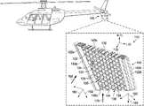
- FIG. 1illustrates a perspective view of an energy attenuating portion in accordance with implementations of various techniques described herein.
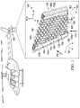
- FIG. 2illustrates an exploded view of an energy attenuating portion in accordance with implementations of various techniques described herein.
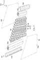
- FIG. 3illustrates a perspective view of an energy attenuating portion in accordance with implementations of various techniques described herein.
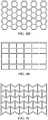
- FIGS. 4A to 4Nillustrate top views of cell shapes in accordance with implementations of various techniques described herein.
- FIGS. 4O to 4Uillustrate cut-away perspective views of cell shapes in accordance with implementations of various techniques described herein.
- FIG. 5is a particular illustrative aspect of methods in accordance with implementations of various techniques described herein.
- Example embodiments of the present disclosureallow for energy from an impact to be attenuated by the stabilizer itself through plastic deformation, such that either minimal or no damage may be transferred to the tail boom/air frame structure of the aircraft.
- energy attenuation capabilitiescan be provided within the sleek airfoil design (i.e., aerodynamic shape) of the stabilizer itself that is optimized for peak aerodynamic performance (e.g., to minimize drag and provide desired aerodynamic force).
- inventive aspects of the present disclosurefurther allow for the capacity to provide for a spectrum of stiffness metrics between rigidity and flexibility according to a particular energy attenuation profile.
- stabilizersmay be constructed to have a certain rigidity (i.e., a first stiffness component) in a first range of directions and certain compressibility (i.e., a second stiffness component) in the second range of directions.
- a certain rigidityi.e., a first stiffness component
- certain compressibilityi.e., a second stiffness component
- FIGS. 1 and 2perspective transparent views of an energy attenuating portion (i.e., an energy offsetting portion, an energy attenuating section) 110 of a stabilizer 100 for an aircraft is shown prior to an impact event ( FIG. 1 ) and after an impact event (i.e., after plastic deformation) ( FIG. 2 ).
- the stabilizer 100may be a vertical stabilizer (i.e., a vertical fin, a tail fin, a vertical plank) or a horizontal stabilizer (i.e., a horizontal fin, a horizontal plank) of the aircraft.
- a vertical stabilizeri.e., a vertical fin, a tail fin, a vertical plank
- a horizontal stabilizeri.e., a horizontal fin, a horizontal plank
- the energy attenuating portion 110may include a first edge section 122 a (i.e., a leading edge), a second edge section (i.e., a trailing edge) 122 b , and an adaptable section 130 (i.e., an adaptable inner section).
- the adaptable section 130may be a lattice-type, porous, structural core and/or orienting core.
- the adaptable section 130may be rigid (i.e., inflexible, stiff) in a first range of directions 162 and may be compressible (i.e., frangible, condensable, collapsible, flexible) in a second range of directions 182 .
- the first range of directions 162may be directions in three-dimensional space (i.e., XYZ-axes) to counter aerodynamic loads (including aerodynamic load 150 (i.e., aerodynamic load vector, drag force vector) that can be countered on X and Z-axes).
- the second range of directions 182may be directions on one or more X-Y planes to counter an impact load (i.e., a vertical impact load, impact load vector) such as impact load 170 .
- the first and second edge sections 122 a , 122 bmay be made of the same rigid material(s) as that of the rest of the stabilizer 100 itself that is optimized for a predefined aerodynamic shape.
- FIGS. 1A-1Bdepict the W-direction (transverse to a ribbon direction), L-direction (corresponding to the ribbon direction), and T-direction that is shown with as an example orientation (i.e., positioning, rotation) that is matched to the X-axis, Y-axis, and Z-axis, respectively.
- orientationi.e., positioning, rotation
- Such an orientationmay be predetermined during construction of the energy attenuating section 110 .
- the adaptable section 130may be adjoined (e.g., bonded via adhesives) or, alternatively, coupled to the first and second edge sections 122 a , 122 b . As illustrated, before an impact event, the adaptable section 130 is positioned proximate to, and in between, the first and second edge sections 122 a , 122 b where the first and second edge sections 122 a , 122 b are situated on opposing sides of the adaptable section 130 .
- the first and edge sections 122 a , 122 b and the adaptable section 130may be distinct regions of the stabilizer 100 that may be either contiguous to or, alternatively, coupled to the stabilizer 100 .
- the first and second edge sections 122 a , 122 bmay be structural and part of the airfoil itself and carry aerodynamic loading such that the first and second edge sections 122 a , 122 b are able to provide aerodynamic lift (i.e., the force that is perpendicular to the oncoming air-flow).
- FIG. 1the first and edge sections 122 a , 122 b and the adaptable section 130 may be distinct regions of the stabilizer 100 that may be either contiguous to or, alternatively, coupled to the stabilizer 100 .
- the first and second edge sections 122 a , 122 bmay be structural and part of the airfoil itself and carry aerodynamic loading such that the first and second edge sections 122 a , 122 b are able to provide aerodynamic lift (i.
- the designcan be formed in other shapes and include wider dimensions (with greater surface area).
- the adaptable section 130is shown to have a significantly wider shape than the first and second edge sections 122 a , 122 b , in alternative implementations, the adaptable section 130 can be formed in other shapes and having narrower dimensions (with lesser surface area).
- the shape and size dimensions of the energy attenuating section 110may be designed according to a precise aerodynamic shape and attenuation profile as per build requirements. Such aerodynamic shape and attenuation profiles correspond to certain stiffness metrics (i.e., corresponding to the extent that the energy attenuating portion 110 may resist deformation in response to aerodynamic and impact forces (i.e. load vectors)).
- the first and second edge sections 122 a , 122 bmay be made of any light-weight but rigid composite core material (e.g., a composite carbon fiber reinforced polyurethane foam) and/or a thin metal (e.g., a metal alloy such as an aluminum or titanium alloy) etc. that can be the same as the other regions of the stabilizer.
- a composite carbon fiber reinforced polyurethane foame.g., a composite carbon fiber reinforced polyurethane foam
- a thin metale.g., a metal alloy such as an aluminum or titanium alloy
- the adaptable section 130may be a lattice-type, porous, structural core and/or an orienting core.
- the adaptable section 130may be made of any light-weight and flexible (i.e., collapsible) core made up of one or more core materials (including reinforced materials) (e.g., thermoplastics (e.g., polyethylene), nomex paper, fabrics, carbon fiber etc.) in a variety of different shapes, layers, and sizes (e.g., as described with reference to FIG. 4 below).
- the adaptable section 130may comprise a plurality of cells 132 (e.g., composite layup of fabric layers (prepreg plies) during construction/orientation).
- the plurality of cells 132may include one or more cell sizes, layers, shapes, and cell densities.
- the inventive aspectsinclude the capacity to vary the attenuating rate (i.e., sink rate, the rate at which the plurality of cells 132 may be configured to receive different magnitudes of energy attenuation from the impact load 170 ).
- each of the plurality of cells 132may include nodes 133 (i.e., the walls of each cell that are parallel to the ribbon direction) and free walls 135 (i.e., the angled walls adjacent to the nodes).
- the nodes 133 of the plurality of cells 132may have a first thickness 134 to transfer aerodynamic loads (such as the aerodynamic load vector 150 on the X and Z-axes) in the first range of directions 162 , while the free walls 135 may have a second thickness 136 to attenuate the impact load (e.g., the impact load 170 ) in a second range of directions 182 .
- the first thickness 134may be greater than the second thickness 136 .
- the varying differences in the first and second thicknesses 134 , 136allow for greater customization of the adaptable section 130 .
- the L-direction (i.e., the ribbon direction) of the plurality of cells 134may be rotated, and as a result, a designer has the capacity to increase or decrease the cumulative thickness for the X and Z-axes (for appropriate reaction to aerodynamic loads such as the aerodynamic load vector 150 ) and the Y-axis (for appropriate reaction to impact loads such as the impact load vector 170 ). Accordingly, the fiber orientation of the plurality of cells 130 may be tailored for both energy attenuation and aerodynamic profiles.
- the stabilizer 100may further include a fiber-laid skin 140 (i.e., an outer skin, an outer encasing) that may fully surround and bond (via an adhesive film) to at least the energy attenuation portion 110 of the stabilizer 100 .
- the fiber-laid skin 140may enclose at least the first and second edge sections 122 a , 122 b and the adaptable section 130 , and provide one or more aerodynamic surfaces for the aerodynamics shape of the airfoil. Accordingly, the fiber-laid skin 140 facilitates the requisite aerodynamic performance (such as to minimize drag and increase lift).
- the outer skin 140may be made from any light-weight material including a fabric (e.g., fabric layers, composite fibers) or a thin metal (e.g., a metal alloy such as an aluminum alloy) etc.
- the fiber-laid skin 140may include at least a first skin portion ( 142 ( a,b ), 145 ( a,b )) (i.e., a first fiber-laid skin portion) and a second skin portion 144 (i.e., a second fiber-laid skin portion).
- the first skin portion 142 amay enclose and bond (via an adhesive film) the first edge section 122 a
- the first skin portion 142 bmay enclose and bond (via an adhesive film) the second edge section 122 b
- the second skin portion 144may enclose and bond (via an adhesive film) lower and/or bottom portions of the adaptable section 130 .
- the at least first and second skin portions 142 ( a,b ), 144may include different tailored composite materials (i.e., fiber-reinforced material) but are made to be contiguous with one another such that the stabilizer 100 can maintain an optimally sleek and precise aerodynamic shape as per build requirements.
- tailored composite materialsi.e., fiber-reinforced material
- the first skin portion 142 ( a,b )may include one or more first materials (e.g., fiber-reinforced rigid composite material such as tailored glass fiber, fiber glass, and thin-metals (e.g., metal alloys)) and the second skin portion 144 may include one or more second materials (i.e., “frangible”, “flimsy”, soft composite material, fabrics (e.g., fabric layers, composite fibers).
- first materialsmay be stiffer than the second materials 145 .
- the first skin portion 145 ( a,b )may also be included on a front side 138 and a back side 139 of the adaptable section 130 .
- the second skin portion 144would be included on bottom portions of the stabilizer 100 .
- the first skin portion 145 ( a,b )may be designed to have sufficient stiffness to optimally react to the aerodynamic load vector 150 in the first range of directions 162
- the second skin portion 144may be designed to have sufficient frangibleness (so as to be “crushed” and attenuate energy) to optimally react to the vertical load vector 170 from impact in the second range of directions 182 .
- FIG. 2illustrates the energy attenuating portion 110 after an impact event, such as when an aircraft contacts the ground during a tail-landing such that the aircraft's stabilizer 100 tilts backward and makes contact with the ground.
- an impact eventsuch as when an aircraft contacts the ground during a tail-landing such that the aircraft's stabilizer 100 tilts backward and makes contact with the ground.
- the adaptable section 130upon the impact event, would at least partially plastically deform (e.g., be compressed), and in other cases, the adaptable section 130 would entirely plastically deform (e.g., be “crushed” or “destroyed”). Also, as shown in FIG.
- the first and second edge sections 122 a , 122 b and the outer skin 140would also detach (e.g., break-off, break apart) from the energy attenuating portion 110 .
- the first edge section 122 a and the first skin portion 142 awould detach together as would the second edge section 122 b and the first skin portion 142 b .
- the second skin portion 144may remain attached to the unaffected (i.e., non-impacted) portion of the adaptable section 130 . Accordingly, in such cases, the section skin portion 144 may break but not completely detach.
- an impact load 170is induced such that normal force is translated in the vertical load vector 170 (having a direction opposite the impact angle 180 ).
- the adaptable section 130may collapse (while the rest of the energy attenuating portion 110 “breaks apart”) and attenuate the magnitude of the normal force.
- stress damage to the tail boom of the aircraftmay be minimized or prevented.
- inventive aspects of the present inventionallow for the capacity to provide for a spectrum of stiffness between rigidity and flexibility in the energy attenuating portion 110 .
- the energy attenuating portion 110may be constructed to have a certain rigidity (i.e., a first stiffness component) in the first range of directions 162 and certain compressibility (i.e., a second stiffness component) in the second range of directions 182 .
- the first range of directions 162relate to the range of directions whereupon the plurality of cells 132 have the capacity to counteract the aerodynamic loads (e.g., the aerodynamic load vector 150 on the Z-directional axis and normal to the stabilizer 100 ). Each individual direction in the first range of directions 162 corresponds to a different first stiffness component having a different stiffness magnitude (e.g., low to high) based on the first thickness 134 in the plurality of cells 132 .
- the second range of directions 182relate to the range of directions whereupon the plurality of cells 132 have the capacity to counteract the impact load (e.g., the vertical load vector 170 on one or more X-Y planes). Each individual direction in the second range of directions 182 corresponds to a different second stiffness component having a different stiffness magnitude (low to high) based on the second thickness 136 in the plurality of cells 132 .
- first and second stiffness componentsmay be pre-determine based on various factors including: the bending stiffness, shear stiffness, bending moment at the energy attenuating portion 110 , and the allowable shear stress of the energy attenuation portion 110 .
- the first and second stiffness componentsmay also account for the variability in the specific cell shapes, layers, sizes, and wall thicknesses that make up the plurality of cells 132 . Further consideration may also be given to, inter alia, the gross weight of the aircraft, landing gear geometry, and whether the aircraft may be intended for vertical landing.
- a stiffness metricmay be computed based on a combination of the first and second stiffness components considering the specific build requirements.
- the stiffness metricmay define and correspond to a specific orientation angle of the adaptable section 130 for an optimal attenuation and aerodynamic profile of the stabilizer 100 .
- the designermay rotate (i.e., position, angle) (one or more composite layups/carbon fibers of) the plurality of cells 132 that make up the adaptable section 130 in the L-direction (i.e., the ribbon direction) and W-direction (i.e., the direction transverse to the ribbon direction) (i.e., on the X-Y plane).
- the adaptable section 130can vary the attenuating rate (i.e., sink rate), the rate at which the plurality of cells 132 may be configured to receive different magnitudes of energy from impact loads.
- the plurality of cells 132may be rotated “clockwise” in the L and W-directions until that the L-direction is transverse to an angled impact load (e.g., that impacts the stabilizer 100 at approximately 45°). Accordingly, upon an impact event, the angled impact load may fully attenuate the adaptable section 130 .
- the plurality of cells 132 that make up the adaptable section 130may be rotated clockwise 45° (from what is shown in FIG. 1 ) in the L-direction and W-direction to counter the impact load 170 (that would make contact with the stabilizer 100 at approximately 90° (i.e., on the Y-axis)).
- the energy attenuating portion 130may now have medium compressibility.
- the L-direction W-direction, and T-directionmay be approximately identical to the X-axis, Y-axis, and Z-axis, respectively, of the stabilizer 100 .
- there would be maximum stiffness for aerodynamic loads(as the ribbon direction is approximately the same as, for example, the aerodynamic load vector 150 ), and maximum compressibility for the impact load vector 170 that is substantially transverse to the ribbon direction upon stabilizer impact with the ground.
- the energy attenuating portion 110allows for the energy to be attenuated during an impact event such that either minimal or no damage may be translated from the stabilizer 100 to the airframe structure of the aircraft.
- the energy attenuation capacityis integral within the aerodynamic shape of the stabilizer 100 necessary for optimal aircraft performance.
- the stabilizer 100includes a precise size and shape, and exact dimension angles that are based on computational fluid dynamics and flight tests.
- One further advantage resulting from the elimination of the tail skid in the inventive aspectsis the capacity to design the stabilizer with greater surface area.
- aircraft designersideally prefer having to the extent possible equivalent surface area on both top and bottom sides of a tail boom centerline axis.
- the torsional load and stresses on the tail boommay be substantially neutralized.
- a greater flare angle for landing as well as a greater ground clearance when landing on uneven soilmay also be realized.
- FIG. 3a perspective transparent view of an energy attenuating portion (i.e., an energy offsetting portion, an energy attenuating section) 110 of a stabilizer 300 for an aircraft is shown prior to an impact event.
- the stabilizer 300may be a vertical stabilizer (i.e., a vertical fin, a tail fin, a vertical plank) or a horizontal stabilizer (i.e., a horizontal fin, a horizontal plank) of the aircraft.
- the energy attenuating portion 310is substantially similar in construction, materials, and operation to the energy attenuating portion 110 in FIG.
- the energy attenuating portion 110may include a fiber-laid skin 140 (i.e., an outer skin, an outer encasing) and an adaptable section 130 (i.e., an adaptable inner section) enclosed within the fiber-laid skin 140 .
- the fiber-laid skin 140may fully surround at least the energy attenuation portion 310 of the stabilizer 100 .
- the fiber-laid skin 140provide one or more aerodynamic surfaces for the aerodynamics shape of the airfoil. Accordingly, the fiber-laid skin 140 facilitates the requisite aerodynamic performance (such as to minimize drag and increase lift).
- the fiber-laid skin 140may include at least a first skin portion ( 142 ( a,b ), 145 ( a,b )) (i.e., a first fiber-laid skin portion) and a second skin portion 144 (i.e., a second fiber-laid skin portion).
- the first skin portion 142 ( a,b )may enclose and bond (via an adhesive film) to side edges of the adaptable portion 130
- the second skin portion 144may enclose and bond (via an adhesive film) to the lower and/or bottom portions of the adaptable section 130 . Similar to FIG.
- the at least first and second skin portions 142 ( a,b ), 144may include different tailored composite materials (i.e., fiber-reinforced material) but are made to be contiguous with one another such that the stabilizer 100 can maintain an optimally sleek and precise aerodynamic shape as per build requirements.
- the first skin portion 145 ( a,b )may also be included on a front side 138 and a back side 139 of the adaptable section 130 .
- the second skin portion 144would be included on bottom portions of the stabilizer 100 .
- first skin portion 145( a,b ) may be designed to have sufficient stiffness to optimally react to the aerodynamic load vector 150 in the first range of directions 162
- second skin portion 144may be designed to have sufficient frangibleness (so as to be “crushed” and attenuate energy) to optimally react to the vertical load vector 170 from impact in the second range of directions 182 .
- the energy attenuating portion 310may at least partially plastically deform (e.g., be compressed). In other cases, the adaptable section 130 may entirely plastically deform (e.g., be “crushed” or “destroyed”). Also, as a result of the impact, the outer skin 140 (including first and second skin portions 142 ( a,b ), 144 ) would detach (e.g., break-off, break apart) from the energy attenuating portion 310 .
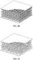
- FIG. 4A to FIG. 4Villustrate various lattice structures having various cell shapes that may be implemented in the adaptable section 130 (as shown in FIGS. 1-3 ) including, for example, but not limited to, (a) Honeycomb with hexagonal cells, (b) Honeycomb with square cells, (c) Honeycomb with triangular cells, (d) Honeycomb with columnar cells, (e) Honeycomb with rectangular cells, (f) Honeycomb with reentrant hexangular cells, (g) Honeycomb with square super cells constructed from mix of square and triangle shapes, (h) Honeycomb with 3D-kagom ⁇ , (i) Honeycomb with flex-core cells, (j) Honeycomb with double-flex cells, (k) Honeycomb with reinforced hexagonal cells, (l) Honeycomb with tri-chiral cells, (m) Honeycomb with hexachiral cells, (n) Truss, (o) Corrugation, (p) Pyramidal, (q) Tetrahedral, (r) Diamond Textile, (s) Square Textile, (t
- lattice structure types and cellular shapesmay be used in lay-up construction of the adaptable section 130 .
- such lattice structure types and cellular shapesprovide stiffness “out-of-plane”, while providing “softness” (i.e., flexibility) “in-plane” (i.e., where the ground makes contact upon an impact event).
- the method 500includes forming an energy attenuation portion 110 , 310 comprising the following steps.
- the method 500may be performed with any of the adaptable section 130 cell shapes described herein with reference to FIG. 4 .
- the method 500includes laying-up, in a distal region of the stabilizer, an adaptable section having a plurality of cells.
- an adaptable section 130may be formed having a plurality of carbon fiber cells 132 .
- lay-up proceduresmay be designed and performed through computer aided design (CAD) and/or computer aided manufacturing (CAM)/additive manufacturing (AM) (i.e., 3D printing)) utilizing automated composite lay-up technologies such as automated tape lay-up (ATL) and automated fiber placement (AFP).
- CADcomputer aided design
- CAMcomputer aided manufacturing
- AMadditive manufacturing
- ATLautomated tape lay-up
- AFPautomated fiber placement
- the method 500includes determining a first stiffness component of the adaptable section corresponding to a first direction in a first range of directions.
- the first stiffness componentmay be determined corresponding to a first direction in a first range of directions 162 (to counteract the aerodynamic loads, such as aerodynamic load vector 150 ).
- computing processes, such as first stiffness component algorithmsmay be automated through CAD and/or CAM/AM software.
- the method 500includes determining a second stiffness component of the adaptable section corresponding to a second direction in a second range of directions.
- the second stiffness componentmay be determined corresponding to a second direction in a second range of directions 182 (to counteract the impact load vector 170 ).
- computing processessuch as second stiffness component algorithms, may be automated through CAD and/or CAM/AM software.
- the method 500includes computing a stiffness metric based on the first stiffness component and the second stiffness component.
- the stiffness metricmay be computed based on the first and second stiffness components to obtain a specific aerodynamic and/or attenuation profile.
- computing processessuch as stiffness metric algorithms, may be automated through CAD and/or CAM/AM software.
- the method 500includes positioning, in the distal region, the adaptable section based on the stiffness metric.
- the adaptable section 130(including the plurality of cells therein) may be positioned based on the computed stiffness metric (to optimally orient the adaptable section 130 according to a specific aerodynamic and attenuation profile) in the distal region (on the tip) of the stabilizer.
- the adaptable section positioning processmay be designed and performed through CAD and/or CAM/AM utilizing automated composite lay-up technologies such as ATP and AFP.
- the method 500may include an additional step such as: forming the energy attenuating portion 110 , 310 by forming first and second edge sections 122 ( a,b ), 124 on opposing sides of the adaptable section 130 .
- the method 500may include an additional step such as: forming the energy attenuating portion 110 , 310 by arranging a fiber-laid skin 140 around the energy attenuating portion 110 , 310 , where the fiber-laid skin 140 includes at least first and second fiber-laid skin portions 142 ( a,b ), 144 , where the first fiber-laid skin portion 142 ( a,b ) includes one or more rigid materials, and where the second fiber-laid skin portion 144 includes one or more frangible materials.
- the method 500may include an additional step such as: arranging the fiber-laid skin 140 by arranging the first fiber laid skin portion 142 ( a,b ) around the first and second edge sections 122 ( a,b ), and arranging the second fiber-laid skin portion 144 at least partially around the adaptable section 130 .
- Each of the processes of illustrative method 500may be performed or carried out by a system integrator, a third party, and/or an operator (e.g., an aerodynamicist or an aerospace designer).
- a system integratormay include, without limitation, any number of manufacturers and major-system subcontractors;
- a third partymay include, without limitation, any number of vendors, subcontractors, and suppliers; and
- an operatormay be a leasing company, military entity, service organization, and so on.
- first”, “second”, etc.are used herein merely as labels, and are not intended to impose ordinal, positional, or hierarchical requirements on the items to which these terms refer. Moreover, reference to, e.g., a “second” item does not require or preclude the existence of, e.g., a “first” or lower-numbered item, and/or, e.g., a “third” or higher-numbered item.
Landscapes
- Engineering & Computer Science (AREA)
- Aviation & Aerospace Engineering (AREA)
- Manufacturing & Machinery (AREA)
- Mechanical Engineering (AREA)
- Transportation (AREA)
- Moulding By Coating Moulds (AREA)
- Laminated Bodies (AREA)
Abstract
Description
Claims (12)
Priority Applications (2)
| Application Number | Priority Date | Filing Date | Title |
|---|---|---|---|
| US16/399,936US11459085B2 (en) | 2019-04-30 | 2019-04-30 | Energy attenuation stabilizers and methods |
| US17/958,901US11834177B2 (en) | 2019-04-30 | 2022-10-03 | Energy attenuation stabilizers and methods |
Applications Claiming Priority (1)
| Application Number | Priority Date | Filing Date | Title |
|---|---|---|---|
| US16/399,936US11459085B2 (en) | 2019-04-30 | 2019-04-30 | Energy attenuation stabilizers and methods |
Related Child Applications (1)
| Application Number | Title | Priority Date | Filing Date |
|---|---|---|---|
| US17/958,901ContinuationUS11834177B2 (en) | 2019-04-30 | 2022-10-03 | Energy attenuation stabilizers and methods |
Publications (2)
| Publication Number | Publication Date |
|---|---|
| US20200346737A1 US20200346737A1 (en) | 2020-11-05 |
| US11459085B2true US11459085B2 (en) | 2022-10-04 |
Family
ID=73017249
Family Applications (2)
| Application Number | Title | Priority Date | Filing Date |
|---|---|---|---|
| US16/399,936Active2039-09-06US11459085B2 (en) | 2019-04-30 | 2019-04-30 | Energy attenuation stabilizers and methods |
| US17/958,901ActiveUS11834177B2 (en) | 2019-04-30 | 2022-10-03 | Energy attenuation stabilizers and methods |
Family Applications After (1)
| Application Number | Title | Priority Date | Filing Date |
|---|---|---|---|
| US17/958,901ActiveUS11834177B2 (en) | 2019-04-30 | 2022-10-03 | Energy attenuation stabilizers and methods |
Country Status (1)
| Country | Link |
|---|---|
| US (2) | US11459085B2 (en) |
Families Citing this family (7)
| Publication number | Priority date | Publication date | Assignee | Title |
|---|---|---|---|---|
| US11459085B2 (en)* | 2019-04-30 | 2022-10-04 | Textron Innovations Inc. | Energy attenuation stabilizers and methods |
| US11518502B2 (en)* | 2019-04-30 | 2022-12-06 | Textron Innovations Inc. | Energy absorption stabilizers and methods |
| USD1040728S1 (en)* | 2021-05-18 | 2024-09-03 | Leonardo S.P.A. | Helicopter |
| USD1041386S1 (en)* | 2021-05-18 | 2024-09-10 | Leonardo S.P.A. | Helicopter toy |
| CN114352331B (en)* | 2021-11-16 | 2024-02-09 | 重庆大学 | Anti-integrated energy-absorbing impact-resistant anchor rod and impact-resistant method thereof |
| FR3132501A1 (en)* | 2022-02-04 | 2023-08-11 | Airbus Operations | Device and method for damping and protection during a sliding phase for a part of an aircraft. |
| CN119590645B (en)* | 2025-02-10 | 2025-05-23 | 北京理工大学 | Anti-collision structure of spacecraft, and spacecraft |
Citations (55)
| Publication number | Priority date | Publication date | Assignee | Title |
|---|---|---|---|---|
| US1749293A (en)* | 1929-07-24 | 1930-03-04 | Caleb J Marston | Aeroplane wing rib |
| US1781160A (en)* | 1929-04-02 | 1930-11-11 | Cairns Dev Company | Aerofoil |
| US1887627A (en)* | 1931-05-26 | 1932-11-15 | Finger Salo Cyrus | Method and means of fabricating structures of metal and nonmetallic materials |
| US1956823A (en)* | 1929-06-13 | 1934-05-01 | Cairns Dev Company | Wing structure |
| US1988085A (en)* | 1932-10-20 | 1935-01-15 | Curtiss Aeroplane & Motor Co | Structural joint |
| US2372510A (en)* | 1943-03-22 | 1945-03-27 | Robert W Mitchell | Structural unit for aircraft and the like |
| US4051289A (en)* | 1976-04-12 | 1977-09-27 | General Electric Company | Composite airfoil construction |
| US4302155A (en)* | 1979-01-08 | 1981-11-24 | Hartzell Propeller, Inc. | Air craft propeller assembly with composite blades |
| US4535958A (en)* | 1982-12-13 | 1985-08-20 | Hutchison Gary A | Aluminum composite spar wing structure and method of assembly |
| US4538780A (en)* | 1983-09-26 | 1985-09-03 | The Boeing Company | Ultralight composite wing structure |
| US4557961A (en)* | 1983-05-27 | 1985-12-10 | The Boeing Company | Light-weight, fire-retardant structural panel |
| US4565595A (en)* | 1981-09-30 | 1986-01-21 | The Boeing Company | Method of making composite aircraft wing |
| US4662587A (en)* | 1981-09-30 | 1987-05-05 | The Boeing Company | Composite for aircraft wing and method of making |
| US4687162A (en)* | 1985-06-25 | 1987-08-18 | The Boeing Company | Apparatus for supporting an aircraft guide track for a movable airfoil |
| US4687691A (en)* | 1986-04-28 | 1987-08-18 | United Technologies Corporation | Honeycomb spliced multilayer foam core aircraft composite parts and method for making same |
| US4962904A (en)* | 1984-06-07 | 1990-10-16 | The Boeing Company | Transition fitting for high strength composite |
| US5216799A (en)* | 1990-11-09 | 1993-06-08 | British Aerospace Public Limited Company | Carbon fibre composite wing manufacture |
| US5332178A (en)* | 1992-06-05 | 1994-07-26 | Williams International Corporation | Composite wing and manufacturing process thereof |
| US5476704A (en)* | 1992-07-01 | 1995-12-19 | Hoac-Austria Flugzeugwerk Wr.Neustadt Gesellschaft M.B.H. | Plastic-composite profiled girder, in particular a wing spar for aircraft and for wind-turbine rotors |
| US5484221A (en)* | 1994-03-07 | 1996-01-16 | Rockwell International Corp. | Panel mounting system |
| US5501414A (en)* | 1993-05-11 | 1996-03-26 | Deutsche Aerospace Airbus Gmbh | Structure having an aerodynamic surface for an aircraft |
| US5624622A (en)* | 1993-05-04 | 1997-04-29 | Foster-Miller, Inc. | Method of forming a truss reinforced foam core sandwich structure |
| US5848765A (en)* | 1996-06-20 | 1998-12-15 | The Boeing Company | Reduced amplitude corrugated web spar |
| US6050523A (en)* | 1996-11-27 | 2000-04-18 | Daimlerchrysler Aerospace Airbus Gmbh | Leading edge construction for an aerodynamic surface and method of making the same |
| US6116539A (en)* | 1999-03-19 | 2000-09-12 | Williams International Co. L.L.C. | Aeroelastically stable forward swept wing |
| US6179086B1 (en)* | 1998-02-06 | 2001-01-30 | Eurocopter Deutschland Gmbh | Noise attenuating sandwich composite panel |
| US6237873B1 (en)* | 1998-06-23 | 2001-05-29 | Fuji Jukogyo Kabushiki Kaisha | Composite material wing structure |
| US6267838B1 (en)* | 1995-06-09 | 2001-07-31 | Aerospatiale Societe Nationale Industrielle | Sandwich panel made of a composite material and production method |
| US20020166721A1 (en)* | 2001-05-11 | 2002-11-14 | Monson Robert James | Acoustic attenuator and method of attenuation of noise |
| US6616101B2 (en)* | 2000-07-27 | 2003-09-09 | Construcciones Aeronauticas, S.A. | Leading edge of supporting surfaces of aircraft |
| US6740381B2 (en)* | 1999-12-28 | 2004-05-25 | Webcore Technologies, Inc. | Fiber reinforced composite cores and panels |
| US6851515B2 (en)* | 2000-10-20 | 2005-02-08 | Eurocopter | Soundproofing panel, in particular structural or lining panel for a rotorcraft |
| US6935472B2 (en)* | 2000-04-12 | 2005-08-30 | Eurocopter | Damping structure and applications |
| US20050194210A1 (en)* | 2004-03-08 | 2005-09-08 | The Boeing Company | Apparatus and method for aircraft cabin noise attenuation via non-obstructive particle damping |
| US20060065784A1 (en)* | 2004-06-11 | 2006-03-30 | Francois Rouyre | Aircraft provided with a belly fairing, and corresponding belly fairing |
| US20060243854A1 (en)* | 2005-02-24 | 2006-11-02 | Sikorsky Aircraft Corporation | Energy absorbing airframe for a vertical lift vehicle |
| US7419031B2 (en)* | 2005-11-04 | 2008-09-02 | The Boeing Company | Integrally damped composite aircraft floor panels |
| US20080277057A1 (en)* | 2007-01-23 | 2008-11-13 | The Boeing Company | Composite laminate having a damping interlayer and method of making the same |
| US20090184206A1 (en)* | 2008-01-18 | 2009-07-23 | The Boeing Company | Particle-filled wing-to-body fairing |
| US7731128B2 (en)* | 2004-01-22 | 2010-06-08 | Sonaca S.A. | Mobile leading edge flap for a main wing of the aerofoils of an aircraft and main wing provided with such a flap |
| US20120024646A1 (en)* | 2009-04-09 | 2012-02-02 | Kabushiki Kaisha Kobe Seiko Sho (Kobe Steel, Ltd.) | Damping structure |
| US8292214B2 (en)* | 2008-01-18 | 2012-10-23 | The Boeing Company | Vibration damping for wing-to-body aircraft fairing |
| US20150298787A1 (en)* | 2012-11-20 | 2015-10-22 | Saab Ab | An airframe leading edge |
| US20150344119A1 (en)* | 2014-05-30 | 2015-12-03 | Airbus Operations (Sas) | Sliding connection between the floor structure and the hull structure of an aircraft |
| US20160076699A1 (en)* | 2014-09-11 | 2016-03-17 | Mindaugas Ramaska | Symmetrical Continuous Multidirectional Ultra-Light Ultra-Strong Structure |
| US9289927B2 (en)* | 2005-05-27 | 2016-03-22 | Airbus Operations Gmbh | Reinforcement of cellular materials |
| US9381992B2 (en)* | 2013-12-23 | 2016-07-05 | Airbus Operations S.L. | Leading edge for an aircraft lifting surface |
| US20160215646A1 (en)* | 2013-09-06 | 2016-07-28 | General Electric Company | Gas turbine laminate seal assembly comprising first and second honeycomb layer and a perforated intermediate seal plate in-between |
| US9611030B2 (en)* | 2012-12-27 | 2017-04-04 | Airbus Group Sas | Energy absorption device for aircraft structural element |
| US9637212B2 (en)* | 2014-04-10 | 2017-05-02 | The Boeing Company | Aircraft body mounted energy absorbing rub strip |
| US20170334552A1 (en)* | 2016-05-17 | 2017-11-23 | Bell Helicopter Textron Inc. | Aircraft load and vibration attenuation |
| US9878770B2 (en)* | 2008-03-28 | 2018-01-30 | Airbus Operations Gmbh | Aircraft fuselage having burnthrough resistant components |
| US10086921B2 (en)* | 2005-10-31 | 2018-10-02 | The Boeing Company | Aircraft having a forward-facing section that deflects elastically under impact loads |
| US20190071163A1 (en)* | 2017-09-05 | 2019-03-07 | The Boeing Company | Energy-absorbing under-floor airframe |
| US20190077093A1 (en)* | 2017-09-12 | 2019-03-14 | The Boeing Company | Stiffened Panels |
Family Cites Families (16)
| Publication number | Priority date | Publication date | Assignee | Title |
|---|---|---|---|---|
| US4478379A (en)* | 1981-05-28 | 1984-10-23 | Canadair Limited | Unmanned remotely piloted aircraft |
| US4815678A (en)* | 1987-12-04 | 1989-03-28 | The Boeing Company | Pivotally mounted high energy absorbing aircraft tail skid assembly having predetermined failure mode |
| JPH11512366A (en)* | 1995-09-14 | 1999-10-26 | シコルスキー エアクラフト コーポレイション | Energy-absorbing landing gear / tailpipe slider including means for indicating the magnitude of the impact load |
| FR2816704B1 (en)* | 2000-11-14 | 2003-02-21 | Eads Airbus Sa | METHOD AND DEVICE FOR DETECTING THE ENVOL OF AN AIRCRAFT UNDER TAKE-OFF |
| US6845944B2 (en)* | 2003-04-11 | 2005-01-25 | The Boeing Company | Multi-positional tail skids and associated methods of use |
| FR2949431B1 (en)* | 2009-09-02 | 2011-07-29 | Eurocopter France | REUSABLE GIRAVION SABOT, AND GIRAVION PROVIDED WITH SUCH A SABOT |
| US9731821B2 (en)* | 2014-09-10 | 2017-08-15 | International Business Machines Corporation | Package transport by unmanned aerial vehicles |
| US10093406B2 (en)* | 2014-12-10 | 2018-10-09 | The Boeing Company | Aircraft frame for tailstrike angle enhancement |
| US9676481B1 (en)* | 2015-03-27 | 2017-06-13 | Amazon Technologies, Inc. | Tether compensated airborne delivery |
| WO2016167865A1 (en)* | 2015-04-16 | 2016-10-20 | Sikorsky Aircraft Corporation | Gust alleviating control for a coaxial rotary wing aircraft |
| US9758233B2 (en)* | 2015-08-31 | 2017-09-12 | The Boeing Company | Support system having a crown integration panel (CIP) |
| WO2017044388A1 (en)* | 2015-09-11 | 2017-03-16 | Northrop Grumman Systems Corporation | Vertical takeoff and landing (vtol) unmanned aerial vehicle (uav) |
| US10604252B2 (en)* | 2016-11-22 | 2020-03-31 | Wing Aviation Llc | Landing and payload loading structures |
| EP3335986B1 (en)* | 2016-12-19 | 2019-11-20 | Airbus Operations S.L. | Impact resistant dorsal fin |
| US10669004B2 (en)* | 2017-03-30 | 2020-06-02 | Sikorsky Aircraft Corporation | Crash energy attenuation system for a transmission support in a vertical lift aircraft |
| US11459085B2 (en)* | 2019-04-30 | 2022-10-04 | Textron Innovations Inc. | Energy attenuation stabilizers and methods |
- 2019
- 2019-04-30USUS16/399,936patent/US11459085B2/enactiveActive
- 2022
- 2022-10-03USUS17/958,901patent/US11834177B2/enactiveActive
Patent Citations (58)
| Publication number | Priority date | Publication date | Assignee | Title |
|---|---|---|---|---|
| US1781160A (en)* | 1929-04-02 | 1930-11-11 | Cairns Dev Company | Aerofoil |
| US1956823A (en)* | 1929-06-13 | 1934-05-01 | Cairns Dev Company | Wing structure |
| US1749293A (en)* | 1929-07-24 | 1930-03-04 | Caleb J Marston | Aeroplane wing rib |
| US1887627A (en)* | 1931-05-26 | 1932-11-15 | Finger Salo Cyrus | Method and means of fabricating structures of metal and nonmetallic materials |
| US1988085A (en)* | 1932-10-20 | 1935-01-15 | Curtiss Aeroplane & Motor Co | Structural joint |
| US2372510A (en)* | 1943-03-22 | 1945-03-27 | Robert W Mitchell | Structural unit for aircraft and the like |
| US4051289A (en)* | 1976-04-12 | 1977-09-27 | General Electric Company | Composite airfoil construction |
| US4302155A (en)* | 1979-01-08 | 1981-11-24 | Hartzell Propeller, Inc. | Air craft propeller assembly with composite blades |
| US4565595A (en)* | 1981-09-30 | 1986-01-21 | The Boeing Company | Method of making composite aircraft wing |
| US4662587A (en)* | 1981-09-30 | 1987-05-05 | The Boeing Company | Composite for aircraft wing and method of making |
| US4535958A (en)* | 1982-12-13 | 1985-08-20 | Hutchison Gary A | Aluminum composite spar wing structure and method of assembly |
| US4557961A (en)* | 1983-05-27 | 1985-12-10 | The Boeing Company | Light-weight, fire-retardant structural panel |
| US4538780A (en)* | 1983-09-26 | 1985-09-03 | The Boeing Company | Ultralight composite wing structure |
| US4962904A (en)* | 1984-06-07 | 1990-10-16 | The Boeing Company | Transition fitting for high strength composite |
| US4687162A (en)* | 1985-06-25 | 1987-08-18 | The Boeing Company | Apparatus for supporting an aircraft guide track for a movable airfoil |
| US4687691A (en)* | 1986-04-28 | 1987-08-18 | United Technologies Corporation | Honeycomb spliced multilayer foam core aircraft composite parts and method for making same |
| US5216799A (en)* | 1990-11-09 | 1993-06-08 | British Aerospace Public Limited Company | Carbon fibre composite wing manufacture |
| US5332178A (en)* | 1992-06-05 | 1994-07-26 | Williams International Corporation | Composite wing and manufacturing process thereof |
| US5476704A (en)* | 1992-07-01 | 1995-12-19 | Hoac-Austria Flugzeugwerk Wr.Neustadt Gesellschaft M.B.H. | Plastic-composite profiled girder, in particular a wing spar for aircraft and for wind-turbine rotors |
| US5624622A (en)* | 1993-05-04 | 1997-04-29 | Foster-Miller, Inc. | Method of forming a truss reinforced foam core sandwich structure |
| US5501414A (en)* | 1993-05-11 | 1996-03-26 | Deutsche Aerospace Airbus Gmbh | Structure having an aerodynamic surface for an aircraft |
| US5484221A (en)* | 1994-03-07 | 1996-01-16 | Rockwell International Corp. | Panel mounting system |
| US6267838B1 (en)* | 1995-06-09 | 2001-07-31 | Aerospatiale Societe Nationale Industrielle | Sandwich panel made of a composite material and production method |
| US5848765A (en)* | 1996-06-20 | 1998-12-15 | The Boeing Company | Reduced amplitude corrugated web spar |
| US6050523A (en)* | 1996-11-27 | 2000-04-18 | Daimlerchrysler Aerospace Airbus Gmbh | Leading edge construction for an aerodynamic surface and method of making the same |
| US6179086B1 (en)* | 1998-02-06 | 2001-01-30 | Eurocopter Deutschland Gmbh | Noise attenuating sandwich composite panel |
| US6237873B1 (en)* | 1998-06-23 | 2001-05-29 | Fuji Jukogyo Kabushiki Kaisha | Composite material wing structure |
| US6116539A (en)* | 1999-03-19 | 2000-09-12 | Williams International Co. L.L.C. | Aeroelastically stable forward swept wing |
| US6740381B2 (en)* | 1999-12-28 | 2004-05-25 | Webcore Technologies, Inc. | Fiber reinforced composite cores and panels |
| US6935472B2 (en)* | 2000-04-12 | 2005-08-30 | Eurocopter | Damping structure and applications |
| US6616101B2 (en)* | 2000-07-27 | 2003-09-09 | Construcciones Aeronauticas, S.A. | Leading edge of supporting surfaces of aircraft |
| US6851515B2 (en)* | 2000-10-20 | 2005-02-08 | Eurocopter | Soundproofing panel, in particular structural or lining panel for a rotorcraft |
| US20020166721A1 (en)* | 2001-05-11 | 2002-11-14 | Monson Robert James | Acoustic attenuator and method of attenuation of noise |
| US7731128B2 (en)* | 2004-01-22 | 2010-06-08 | Sonaca S.A. | Mobile leading edge flap for a main wing of the aerofoils of an aircraft and main wing provided with such a flap |
| US20050194210A1 (en)* | 2004-03-08 | 2005-09-08 | The Boeing Company | Apparatus and method for aircraft cabin noise attenuation via non-obstructive particle damping |
| US20060065784A1 (en)* | 2004-06-11 | 2006-03-30 | Francois Rouyre | Aircraft provided with a belly fairing, and corresponding belly fairing |
| US20060243854A1 (en)* | 2005-02-24 | 2006-11-02 | Sikorsky Aircraft Corporation | Energy absorbing airframe for a vertical lift vehicle |
| US9289927B2 (en)* | 2005-05-27 | 2016-03-22 | Airbus Operations Gmbh | Reinforcement of cellular materials |
| US10086921B2 (en)* | 2005-10-31 | 2018-10-02 | The Boeing Company | Aircraft having a forward-facing section that deflects elastically under impact loads |
| US7419031B2 (en)* | 2005-11-04 | 2008-09-02 | The Boeing Company | Integrally damped composite aircraft floor panels |
| US20080277057A1 (en)* | 2007-01-23 | 2008-11-13 | The Boeing Company | Composite laminate having a damping interlayer and method of making the same |
| US8292214B2 (en)* | 2008-01-18 | 2012-10-23 | The Boeing Company | Vibration damping for wing-to-body aircraft fairing |
| US8056850B2 (en)* | 2008-01-18 | 2011-11-15 | The Boeing Company | Particle-filled wing-to-body fairing and method for reducing fairing vibrations |
| US20090184206A1 (en)* | 2008-01-18 | 2009-07-23 | The Boeing Company | Particle-filled wing-to-body fairing |
| US9878770B2 (en)* | 2008-03-28 | 2018-01-30 | Airbus Operations Gmbh | Aircraft fuselage having burnthrough resistant components |
| US20120024646A1 (en)* | 2009-04-09 | 2012-02-02 | Kabushiki Kaisha Kobe Seiko Sho (Kobe Steel, Ltd.) | Damping structure |
| US20150298787A1 (en)* | 2012-11-20 | 2015-10-22 | Saab Ab | An airframe leading edge |
| US10131415B2 (en)* | 2012-11-20 | 2018-11-20 | Saab Ab | Airframe leading edge |
| US9611030B2 (en)* | 2012-12-27 | 2017-04-04 | Airbus Group Sas | Energy absorption device for aircraft structural element |
| US20160215646A1 (en)* | 2013-09-06 | 2016-07-28 | General Electric Company | Gas turbine laminate seal assembly comprising first and second honeycomb layer and a perforated intermediate seal plate in-between |
| US9381992B2 (en)* | 2013-12-23 | 2016-07-05 | Airbus Operations S.L. | Leading edge for an aircraft lifting surface |
| US9637212B2 (en)* | 2014-04-10 | 2017-05-02 | The Boeing Company | Aircraft body mounted energy absorbing rub strip |
| US20150344119A1 (en)* | 2014-05-30 | 2015-12-03 | Airbus Operations (Sas) | Sliding connection between the floor structure and the hull structure of an aircraft |
| US20160076699A1 (en)* | 2014-09-11 | 2016-03-17 | Mindaugas Ramaska | Symmetrical Continuous Multidirectional Ultra-Light Ultra-Strong Structure |
| US20170334552A1 (en)* | 2016-05-17 | 2017-11-23 | Bell Helicopter Textron Inc. | Aircraft load and vibration attenuation |
| US10647418B2 (en)* | 2016-05-17 | 2020-05-12 | Bell Helicopter Textron Inc. | Aircraft load and vibration attenuation |
| US20190071163A1 (en)* | 2017-09-05 | 2019-03-07 | The Boeing Company | Energy-absorbing under-floor airframe |
| US20190077093A1 (en)* | 2017-09-12 | 2019-03-14 | The Boeing Company | Stiffened Panels |
Non-Patent Citations (1)
| Title |
|---|
| Laurent Wahl et al.; Date: Oct. 2011; Shear Stresses in Honeycomb Sandwich Plates: Analytical Solution; FEM and Experimental Verification; University of Luxembourg Oct. 2011; pp. 12 and 17.* |
Also Published As
| Publication number | Publication date |
|---|---|
| US20200346737A1 (en) | 2020-11-05 |
| US20230038129A1 (en) | 2023-02-09 |
| US11834177B2 (en) | 2023-12-05 |
Similar Documents
| Publication | Publication Date | Title |
|---|---|---|
| US11834177B2 (en) | Energy attenuation stabilizers and methods | |
| US10556670B2 (en) | Laminar flow panel | |
| US9862479B1 (en) | Methods of making and structures containing stiffeners having transition portions | |
| US3995080A (en) | Filament reinforced structural shapes | |
| US8540916B2 (en) | Curved structural part made of composite material and a process for manufacturing such a part | |
| CN107082111B (en) | Plate and method for improving laminar flow | |
| Stanford et al. | Trim and structural optimization of subsonic transport wings using nonconventional aeroelastic tailoring | |
| US20130075529A1 (en) | Stabilizer Torque Box Assembly and Method | |
| Gatto et al. | Experimental investigation of bistable winglets to enhance aircraft wing lift takeoff capability | |
| BR112015004962B1 (en) | COMPOSITE STRUCTURE, E, METHOD OF PRODUCTION OF A COMPOSITE STRUCTURE | |
| CN104245295A (en) | Hat stiffeners with canted webs and method of forming the same | |
| CA3042655C (en) | Elongate structures, structural assemblies with elongate structures, and methods for supporting a structural load | |
| US12311615B2 (en) | Flat composite panel with tear arrestment and method of making the same | |
| CN114818444B (en) | Optimal design method and device for fallability of composite skid-type landing gear | |
| JP7752001B2 (en) | Composite Thin Wing Box Architecture for Supersonic Business Jets | |
| EP3450302A1 (en) | Energy-absorbing under-floor airframe | |
| JP6800558B2 (en) | Carbon fiber reinforced polymer cargo beam with integrated cargo post and c-splice | |
| US11623733B2 (en) | Bead-stiffened movable surfaces | |
| Sturm et al. | Morphing forward wing section skin design for a sailplane considering wing bending | |
| Bolshikh | Designing of Aircraft Reinforced Carbon-Composite Torsion Boxes | |
| Fanelli | Structural Design of an Unmanned Blended-Wing-Body Aerial Vehicle | |
| GB2638210A (en) | Composite structure | |
| Lovejoy et al. | Preliminary design and analysis of an in-plane prseus joint | |
| Papadrakakis et al. | STRENGTH AND WEIGHT EQUIVALENT SUBSTITUTION OF LARGE SANDWICH PANELS BY MONOLITHIC CFRP STRUCTURES | |
| McQUILLEN et al. | Graphite-epoxy wing for BQM-34E supersonic aerial target |
Legal Events
| Date | Code | Title | Description |
|---|---|---|---|
| AS | Assignment | Owner name:BELL HELICOPTER TEXTRON INC., TEXAS Free format text:ASSIGNMENT OF ASSIGNORS INTEREST;ASSIGNORS:SINUSAS, ERIC;NOISEUX-BOUCHER, GUILLAUME;BOISVERT, OLIVIER;AND OTHERS;SIGNING DATES FROM 20190418 TO 20190429;REEL/FRAME:049041/0302 | |
| FEPP | Fee payment procedure | Free format text:ENTITY STATUS SET TO UNDISCOUNTED (ORIGINAL EVENT CODE: BIG.); ENTITY STATUS OF PATENT OWNER: LARGE ENTITY | |
| STPP | Information on status: patent application and granting procedure in general | Free format text:NON FINAL ACTION MAILED | |
| STPP | Information on status: patent application and granting procedure in general | Free format text:RESPONSE TO NON-FINAL OFFICE ACTION ENTERED AND FORWARDED TO EXAMINER | |
| STPP | Information on status: patent application and granting procedure in general | Free format text:FINAL REJECTION MAILED | |
| STPP | Information on status: patent application and granting procedure in general | Free format text:ADVISORY ACTION MAILED | |
| STPP | Information on status: patent application and granting procedure in general | Free format text:DOCKETED NEW CASE - READY FOR EXAMINATION | |
| STPP | Information on status: patent application and granting procedure in general | Free format text:NON FINAL ACTION MAILED | |
| STPP | Information on status: patent application and granting procedure in general | Free format text:RESPONSE TO NON-FINAL OFFICE ACTION ENTERED AND FORWARDED TO EXAMINER | |
| STPP | Information on status: patent application and granting procedure in general | Free format text:FINAL REJECTION MAILED | |
| STPP | Information on status: patent application and granting procedure in general | Free format text:RESPONSE AFTER FINAL ACTION FORWARDED TO EXAMINER | |
| STPP | Information on status: patent application and granting procedure in general | Free format text:ADVISORY ACTION MAILED | |
| STPP | Information on status: patent application and granting procedure in general | Free format text:DOCKETED NEW CASE - READY FOR EXAMINATION | |
| STPP | Information on status: patent application and granting procedure in general | Free format text:NOTICE OF ALLOWANCE MAILED -- APPLICATION RECEIVED IN OFFICE OF PUBLICATIONS | |
| AS | Assignment | Owner name:TEXTRON INNOVATIONS INC., RHODE ISLAND Free format text:ASSIGNMENT OF ASSIGNORS INTEREST;ASSIGNOR:BELL TEXTRON RHODE ISLAND INC.;REEL/FRAME:060689/0256 Effective date:20200101 Owner name:BELL TEXTRON RHODE ISLAND INC., RHODE ISLAND Free format text:ASSIGNMENT OF ASSIGNORS INTEREST;ASSIGNOR:BELL TEXTRON INC.;REEL/FRAME:060689/0238 Effective date:20200101 | |
| STPP | Information on status: patent application and granting procedure in general | Free format text:PUBLICATIONS -- ISSUE FEE PAYMENT VERIFIED | |
| STCF | Information on status: patent grant | Free format text:PATENTED CASE | |
| AS | Assignment | Owner name:BELL TEXTRON INC., TEXAS Free format text:CHANGE OF NAME;ASSIGNOR:BELL HELICOPTER TEXTRON INC.;REEL/FRAME:066696/0032 Effective date:20190611 |