US11458679B2 - Lighting for additive manufacturing - Google Patents
Lighting for additive manufacturingDownload PDFInfo
- Publication number
- US11458679B2 US11458679B2US15/513,965US201415513965AUS11458679B2US 11458679 B2US11458679 B2US 11458679B2US 201415513965 AUS201415513965 AUS 201415513965AUS 11458679 B2US11458679 B2US 11458679B2
- Authority
- US
- United States
- Prior art keywords
- light
- build material
- range
- coalescing agent
- light sources
- Prior art date
- Legal status (The legal status is an assumption and is not a legal conclusion. Google has not performed a legal analysis and makes no representation as to the accuracy of the status listed.)
- Active, expires
Links
Images


Classifications
- B—PERFORMING OPERATIONS; TRANSPORTING
- B29—WORKING OF PLASTICS; WORKING OF SUBSTANCES IN A PLASTIC STATE IN GENERAL
- B29C—SHAPING OR JOINING OF PLASTICS; SHAPING OF MATERIAL IN A PLASTIC STATE, NOT OTHERWISE PROVIDED FOR; AFTER-TREATMENT OF THE SHAPED PRODUCTS, e.g. REPAIRING
- B29C64/00—Additive manufacturing, i.e. manufacturing of three-dimensional [3D] objects by additive deposition, additive agglomeration or additive layering, e.g. by 3D printing, stereolithography or selective laser sintering
- B29C64/10—Processes of additive manufacturing
- B29C64/165—Processes of additive manufacturing using a combination of solid and fluid materials, e.g. a powder selectively bound by a liquid binder, catalyst, inhibitor or energy absorber
- B—PERFORMING OPERATIONS; TRANSPORTING
- B29—WORKING OF PLASTICS; WORKING OF SUBSTANCES IN A PLASTIC STATE IN GENERAL
- B29C—SHAPING OR JOINING OF PLASTICS; SHAPING OF MATERIAL IN A PLASTIC STATE, NOT OTHERWISE PROVIDED FOR; AFTER-TREATMENT OF THE SHAPED PRODUCTS, e.g. REPAIRING
- B29C35/00—Heating, cooling or curing, e.g. crosslinking or vulcanising; Apparatus therefor
- B29C35/02—Heating or curing, e.g. crosslinking or vulcanizing during moulding, e.g. in a mould
- B29C35/08—Heating or curing, e.g. crosslinking or vulcanizing during moulding, e.g. in a mould by wave energy or particle radiation
- B29C35/0805—Heating or curing, e.g. crosslinking or vulcanizing during moulding, e.g. in a mould by wave energy or particle radiation using electromagnetic radiation
- B—PERFORMING OPERATIONS; TRANSPORTING
- B29—WORKING OF PLASTICS; WORKING OF SUBSTANCES IN A PLASTIC STATE IN GENERAL
- B29C—SHAPING OR JOINING OF PLASTICS; SHAPING OF MATERIAL IN A PLASTIC STATE, NOT OTHERWISE PROVIDED FOR; AFTER-TREATMENT OF THE SHAPED PRODUCTS, e.g. REPAIRING
- B29C64/00—Additive manufacturing, i.e. manufacturing of three-dimensional [3D] objects by additive deposition, additive agglomeration or additive layering, e.g. by 3D printing, stereolithography or selective laser sintering
- B29C64/20—Apparatus for additive manufacturing; Details thereof or accessories therefor
- B29C64/264—Arrangements for irradiation
- B29C64/268—Arrangements for irradiation using laser beams; using electron beams [EB]
- B—PERFORMING OPERATIONS; TRANSPORTING
- B29—WORKING OF PLASTICS; WORKING OF SUBSTANCES IN A PLASTIC STATE IN GENERAL
- B29C—SHAPING OR JOINING OF PLASTICS; SHAPING OF MATERIAL IN A PLASTIC STATE, NOT OTHERWISE PROVIDED FOR; AFTER-TREATMENT OF THE SHAPED PRODUCTS, e.g. REPAIRING
- B29C64/00—Additive manufacturing, i.e. manufacturing of three-dimensional [3D] objects by additive deposition, additive agglomeration or additive layering, e.g. by 3D printing, stereolithography or selective laser sintering
- B29C64/20—Apparatus for additive manufacturing; Details thereof or accessories therefor
- B29C64/264—Arrangements for irradiation
- B29C64/277—Arrangements for irradiation using multiple radiation means, e.g. micromirrors or multiple light-emitting diodes [LED]
- B—PERFORMING OPERATIONS; TRANSPORTING
- B29—WORKING OF PLASTICS; WORKING OF SUBSTANCES IN A PLASTIC STATE IN GENERAL
- B29C—SHAPING OR JOINING OF PLASTICS; SHAPING OF MATERIAL IN A PLASTIC STATE, NOT OTHERWISE PROVIDED FOR; AFTER-TREATMENT OF THE SHAPED PRODUCTS, e.g. REPAIRING
- B29C64/00—Additive manufacturing, i.e. manufacturing of three-dimensional [3D] objects by additive deposition, additive agglomeration or additive layering, e.g. by 3D printing, stereolithography or selective laser sintering
- B29C64/20—Apparatus for additive manufacturing; Details thereof or accessories therefor
- B29C64/264—Arrangements for irradiation
- B29C64/291—Arrangements for irradiation for operating globally, e.g. together with selectively applied activators or inhibitors
- B—PERFORMING OPERATIONS; TRANSPORTING
- B29—WORKING OF PLASTICS; WORKING OF SUBSTANCES IN A PLASTIC STATE IN GENERAL
- B29C—SHAPING OR JOINING OF PLASTICS; SHAPING OF MATERIAL IN A PLASTIC STATE, NOT OTHERWISE PROVIDED FOR; AFTER-TREATMENT OF THE SHAPED PRODUCTS, e.g. REPAIRING
- B29C67/00—Shaping techniques not covered by groups B29C39/00 - B29C65/00, B29C70/00 or B29C73/00
- B29C67/0007—Manufacturing coloured articles not otherwise provided for, e.g. by colour change
- B—PERFORMING OPERATIONS; TRANSPORTING
- B33—ADDITIVE MANUFACTURING TECHNOLOGY
- B33Y—ADDITIVE MANUFACTURING, i.e. MANUFACTURING OF THREE-DIMENSIONAL [3-D] OBJECTS BY ADDITIVE DEPOSITION, ADDITIVE AGGLOMERATION OR ADDITIVE LAYERING, e.g. BY 3-D PRINTING, STEREOLITHOGRAPHY OR SELECTIVE LASER SINTERING
- B33Y30/00—Apparatus for additive manufacturing; Details thereof or accessories therefor
- B—PERFORMING OPERATIONS; TRANSPORTING
- B29—WORKING OF PLASTICS; WORKING OF SUBSTANCES IN A PLASTIC STATE IN GENERAL
- B29C—SHAPING OR JOINING OF PLASTICS; SHAPING OF MATERIAL IN A PLASTIC STATE, NOT OTHERWISE PROVIDED FOR; AFTER-TREATMENT OF THE SHAPED PRODUCTS, e.g. REPAIRING
- B29C35/00—Heating, cooling or curing, e.g. crosslinking or vulcanising; Apparatus therefor
- B29C35/02—Heating or curing, e.g. crosslinking or vulcanizing during moulding, e.g. in a mould
- B29C35/08—Heating or curing, e.g. crosslinking or vulcanizing during moulding, e.g. in a mould by wave energy or particle radiation
- B29C35/0805—Heating or curing, e.g. crosslinking or vulcanizing during moulding, e.g. in a mould by wave energy or particle radiation using electromagnetic radiation
- B29C2035/0838—Heating or curing, e.g. crosslinking or vulcanizing during moulding, e.g. in a mould by wave energy or particle radiation using electromagnetic radiation using laser
- B—PERFORMING OPERATIONS; TRANSPORTING
- B29—WORKING OF PLASTICS; WORKING OF SUBSTANCES IN A PLASTIC STATE IN GENERAL
- B29C—SHAPING OR JOINING OF PLASTICS; SHAPING OF MATERIAL IN A PLASTIC STATE, NOT OTHERWISE PROVIDED FOR; AFTER-TREATMENT OF THE SHAPED PRODUCTS, e.g. REPAIRING
- B29C64/00—Additive manufacturing, i.e. manufacturing of three-dimensional [3D] objects by additive deposition, additive agglomeration or additive layering, e.g. by 3D printing, stereolithography or selective laser sintering
- B29C64/20—Apparatus for additive manufacturing; Details thereof or accessories therefor
- B29C64/205—Means for applying layers
- B29C64/209—Heads; Nozzles
- B—PERFORMING OPERATIONS; TRANSPORTING
- B33—ADDITIVE MANUFACTURING TECHNOLOGY
- B33Y—ADDITIVE MANUFACTURING, i.e. MANUFACTURING OF THREE-DIMENSIONAL [3-D] OBJECTS BY ADDITIVE DEPOSITION, ADDITIVE AGGLOMERATION OR ADDITIVE LAYERING, e.g. BY 3-D PRINTING, STEREOLITHOGRAPHY OR SELECTIVE LASER SINTERING
- B33Y10/00—Processes of additive manufacturing
Definitions
- FIG. 15is a graph showing one example of spectral intensity as a function of wavelength for monochromatic light sources that emit light near the peak absorptions of some of the coalescing agents shown in FIG. 14 .
- FIG. 16illustrates one example of a processor readable medium with lighting instructions for additive manufacturing.
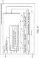
- FIG. 18is a block diagram illustrating one example of an additive manufacturing system implementing a CAD computer program product that includes a processor readable medium with lighting instructions, such as the medium shown in FIG. 16 .
- the intensity of the monochromatic light needed for adequate heatingmay vary depending on the characteristics of the build material and coalescing agent, it is expected that monochromatic light with a spectral intensity at least 1 ⁇ 10 12 Wm ⁇ 3 sr ⁇ 1 (watts per cubic meter per steradian) will be sufficient for many implementations.
- “coalesce”means to become a coherent mass by heating, for example by sintering or melting;
- a “coalescing agent”means a substance that causes or helps cause a build material to coalesce;
- a “coalescence modifier agent”means a substance that inhibits or prevents coalescence of a build material, for example by modifying the effect of a coalescing agent;
- monochromaticmeans within a band of wavelengths 30 nm or narrower; “polychromatic” means a band of wavelengths broader than 30 nm; and
- a “slice”means one or more slices of a multi-slice object or the object itself for a single slice object.
- a first layer 30 of build material 14is formed in manufacturing bed 24 as shown in FIG. 1 (block 102 in FIG. 11 ).
- Individual layers of build material 14may be pre-heated in manufacturing bed 24 , as shown in FIG. 1 (block 104 in FIG. 10 ), or build material 14 may be pre-heated in supply bed 18 , or a combination of heating in both beds 18 and 24 .
- Pre-heatingin this context refers to heating before light is applied to coalesce build material for coalescence, as described below with reference to FIG. 4 .
- a coalescing agent 34is dispensed on to build material 14 in layer 30 in a pattern corresponding to the first object slice (block 106 in FIG. 10 ), for example with an inkjet type dispenser 36 .
- This pattern for coalescing agent 34is depicted by an area 38 of dense stippling in the figures.
- a coalescence modifier agent 40may be dispensed on to build material 14 in layer 30 for example with an inkjet type dispenser 44 , as shown in FIG. 3 (block 108 in FIG. 10 ).
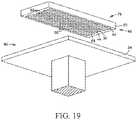
- FIG. 19illustrates one example of a carriage assembly 79 for an additive manufacturing machine such as machine 68 shown in FIGS. 17 and 18 .
- carriage assembly 79includes a carriage 80 carrying agent dispensers 36 , 44 and a light source 48 .
- Carriage 80is movable back and forth over manufacturing bed 24 to dispense coalescing and modifier agents 34 , 40 , for example as shown in FIGS. 2-3 and 6-7 , and to expose patterned build material to monochromatic light 46 , for example as shown in FIGS. 4 and 8 .
- FIG. 19illustrates one example of a carriage assembly 79 for an additive manufacturing machine such as machine 68 shown in FIGS. 17 and 18 .
- carriage assembly 79includes a carriage 80 carrying agent dispensers 36 , 44 and a light source 48 .
- Carriage 80is movable back and forth over manufacturing bed 24 to dispense coalescing and modifier agents 34 , 40 , for example as shown in FIGS. 2-3 and 6-7 , and to expose patterned build material to
- agent dispensers 36 and 44are configured as elongated inkjet printheads that span the width of bed 24 with an array of nozzles 82 through which the agents are dispensed on to build material supported on bed 24 , or that span so much of the width of bed 24 corresponding to a build zone 88 for layering and coalescing the build material. While two printheads 36 , 44 with only a single line of dispensing nozzles are shown, other configurations are possible. For example, more or fewer printheads could be used each with a different array of dispensing nozzles, including printheads and nozzles to dispense multiple different color (or colorless coalescing agents.
- each light bar 84includes a line of monochromatic red light sources, a line of monochromatic green light sources and a line of monochromatic blue light sources to cover corresponding absorption peaks for cyan, magenta, and yellow coalescing agents, respectively.
- Lines or other arrays of multiple monochromatic light sourcesenable manufacturing an object with different color parts using a single light source 48 .
- a first color (or colorless) coalescing agent 34may be dispensed at block 106 in FIG.
Landscapes
- Engineering & Computer Science (AREA)
- Materials Engineering (AREA)
- Chemical & Material Sciences (AREA)
- Physics & Mathematics (AREA)
- Manufacturing & Machinery (AREA)
- Health & Medical Sciences (AREA)
- Mechanical Engineering (AREA)
- Toxicology (AREA)
- Optics & Photonics (AREA)
- Microelectronics & Electronic Packaging (AREA)
- Electromagnetism (AREA)
- Oral & Maxillofacial Surgery (AREA)
- Thermal Sciences (AREA)
- Plasma & Fusion (AREA)
Abstract
Description
Claims (13)
Applications Claiming Priority (1)
| Application Number | Priority Date | Filing Date | Title |
|---|---|---|---|
| PCT/US2014/057651WO2016048348A1 (en) | 2014-09-26 | 2014-09-26 | Lighting for additive manufacturing |
Related Parent Applications (1)
| Application Number | Title | Priority Date | Filing Date |
|---|---|---|---|
| PCT/US2014/057651A-371-Of-InternationalWO2016048348A1 (en) | 2014-09-26 | 2014-09-26 | Lighting for additive manufacturing |
Related Child Applications (1)
| Application Number | Title | Priority Date | Filing Date |
|---|---|---|---|
| US17/878,616ContinuationUS20220362992A1 (en) | 2014-09-26 | 2022-08-01 | Lighting for additive manufacturing |
Publications (2)
| Publication Number | Publication Date |
|---|---|
| US20170361505A1 US20170361505A1 (en) | 2017-12-21 |
| US11458679B2true US11458679B2 (en) | 2022-10-04 |
Family
ID=55581665
Family Applications (2)
| Application Number | Title | Priority Date | Filing Date |
|---|---|---|---|
| US15/513,965Active2037-04-07US11458679B2 (en) | 2014-09-26 | 2014-09-26 | Lighting for additive manufacturing |
| US17/878,616PendingUS20220362992A1 (en) | 2014-09-26 | 2022-08-01 | Lighting for additive manufacturing |
Family Applications After (1)
| Application Number | Title | Priority Date | Filing Date |
|---|---|---|---|
| US17/878,616PendingUS20220362992A1 (en) | 2014-09-26 | 2022-08-01 | Lighting for additive manufacturing |
Country Status (5)
| Country | Link |
|---|---|
| US (2) | US11458679B2 (en) |
| EP (1) | EP3197666B1 (en) |
| CN (2) | CN114474725A (en) |
| TW (2) | TWI656966B (en) |
| WO (1) | WO2016048348A1 (en) |
Families Citing this family (25)
| Publication number | Priority date | Publication date | Assignee | Title |
|---|---|---|---|---|
| WO2016125138A2 (en)* | 2015-02-02 | 2016-08-11 | Massivit 3D Printing Technologies Ltd | A curing system for printing of 3d objects |
| DE102015115810A1 (en) | 2015-09-18 | 2017-03-23 | Osram Opto Semiconductors Gmbh | Optoelectronic semiconductor device and 3D printer |
| DE102015014964A1 (en)* | 2015-11-20 | 2017-05-24 | Voxeljet Ag | Method and apparatus for 3D printing with narrow wavelength spectrum |
| EP3458251A4 (en)* | 2016-05-17 | 2020-01-08 | Hewlett-Packard Development Company, L.P. | 3d printer with tuned fusing radiation emission |
| US11305490B2 (en) | 2016-07-22 | 2022-04-19 | Hewlett-Packard Development Company, L.P. | Additive manufacturing with traversing irradiation region |
| CN109072601B (en) | 2016-07-22 | 2020-11-10 | 惠普发展公司,有限责任合伙企业 | Controlling heating in additive manufacturing |
| EP3442773B1 (en)* | 2016-07-29 | 2023-10-18 | Hewlett-Packard Development Company, L.P. | Laser melting of build materials |
| WO2018080631A1 (en) | 2016-10-25 | 2018-05-03 | Hewlett-Packard Development Company, L.P. | Three-dimensional printing method |
| JP6820400B2 (en) | 2016-10-25 | 2021-01-27 | ヒューレット−パッカード デベロップメント カンパニー エル.ピー.Hewlett‐Packard Development Company, L.P. | Dispersions and injectable compositions containing cesium oxide tungsten nanoparticles and zwitterionic stabilizers |
| EP3397455B1 (en)* | 2016-10-25 | 2022-07-06 | Hewlett-Packard Development Company, L.P. | Three-dimensional (3d) printing |
| CN109963700B (en)* | 2016-11-22 | 2021-08-17 | 科思创德国股份有限公司 | Method and system for making an object by building layer by layer in a stamping method |
| WO2018125630A1 (en)* | 2016-12-29 | 2018-07-05 | 3D Systems, Inc. | Powder-based additive manufacturing temperature control by spatial light modulation |
| WO2018194688A1 (en) | 2017-04-21 | 2018-10-25 | Hewlett-Packard Development Company, L.P. | Additive manufacturing roller within radiative heat transfer area |
| CN110573325A (en) | 2017-04-21 | 2019-12-13 | 惠普发展公司,有限责任合伙企业 | Additive manufacturing machine heat flow |
| WO2019012804A1 (en)* | 2017-07-10 | 2019-01-17 | ソニーセミコンダクタソリューションズ株式会社 | Optical head and molding device |
| WO2019022742A1 (en)* | 2017-07-27 | 2019-01-31 | Hewlett-Packard Development Company, L.P. | Air flow straighteners with silencer |
| US11376797B2 (en)* | 2018-01-16 | 2022-07-05 | Hewlett-Packard Development Company, L.P. | Three dimensional printing system |
| WO2019143324A1 (en)* | 2018-01-17 | 2019-07-25 | Hewlett-Packard Development Company, L.P. | Manufacturing a three-dimensional object |
| WO2019199274A1 (en) | 2018-04-10 | 2019-10-17 | Hewlett-Packard Development Company, L.P. | Preheat build materials with preheating sources |
| CN112823090A (en)* | 2019-02-26 | 2021-05-18 | 惠普发展公司,有限责任合伙企业 | Determining melting energy curves in 3D printing |
| US20220134434A1 (en)* | 2019-07-19 | 2022-05-05 | Hewlett-Packard Development Company, L.P. | Selective energy emission control in 3d fabrication systems |
| WO2021025680A1 (en)* | 2019-08-05 | 2021-02-11 | Hewlett-Packard Development Company, L.P. | Additive manufacturing with laser arrays |
| EP4111351A4 (en) | 2020-03-25 | 2024-03-20 | OPT Industries, Inc. | SYSTEMS, METHODS AND FILE FORMAT FOR 3D PRINTING OF MICROSTRUCTURES |
| CN111605191A (en)* | 2020-06-24 | 2020-09-01 | 深圳市智能派科技有限公司 | A multi-size light-curing 3D printer splicing light source |
| CN120056623B (en)* | 2025-04-28 | 2025-06-27 | 珠海恒茂电子科技有限公司 | Printing method and system for area selected by monochromatic light |
Citations (24)
| Publication number | Priority date | Publication date | Assignee | Title |
|---|---|---|---|---|
| US5942370A (en) | 1991-10-02 | 1999-08-24 | Ciba Specialty Chemicals Corporation | Production of three-dimensional objects |
| WO2001038061A1 (en) | 1999-10-26 | 2001-05-31 | University Of Southern California | Process of making a three-dimensional object |
| JP2002316363A (en) | 2001-02-16 | 2002-10-29 | Fuji Photo Film Co Ltd | Stereolithography device and exposure unit |
| US6531086B1 (en) | 1997-04-30 | 2003-03-11 | Speed Part Rp Ab | Method and device for manufacturing three-dimensional bodies |
| US6658314B1 (en) | 1999-10-06 | 2003-12-02 | Objet Geometries Ltd. | System and method for three dimensional model printing |
| US6849308B1 (en) | 1999-05-27 | 2005-02-01 | Stuart Speakman | Method of forming a masking pattern on a surface |
| US20060134419A1 (en) | 2004-12-21 | 2006-06-22 | Degussa Ag | Use of polyarylene ether ketone powder in a three-dimensional powder-based moldless production process, and moldings produced therefrom |
| US20060180957A1 (en)* | 2003-07-25 | 2006-08-17 | Neil Hopkinson | Method and apparatus for combining particulate material |
| CN1950192A (en) | 2004-03-16 | 2007-04-18 | 德古萨公司 | Method and device for manufacturing three-dimensional objects by laser technology and application of absorbers by inkjet |
| US20070238056A1 (en) | 2004-04-27 | 2007-10-11 | Degussa Ag | Method and Device for Production of Three-Dimensional Objects by Means of Electromagnetic Radiation of Electromagnetic Radiation and Application of an Absorber by Means of an Ink-Jet Method |
| CN101180174A (en) | 2005-05-20 | 2008-05-14 | 亨斯迈先进材料(瑞士)有限公司 | Rapid prototyping apparatus and method of rapid prototyping |
| US20110259862A1 (en) | 2008-09-05 | 2011-10-27 | Mtt Technologies Limited | Additive Manufacturing Apparatus with a Chamber and a Removably-Mountable Optical Module; Method of Preparing a Laser Processing Apparatus with such Removably-Mountable Optical Module |
| US20120139167A1 (en) | 2009-08-18 | 2012-06-07 | Sintermask Gmbh | Method and device for producing a three-dimensional object |
| KR20130013490A (en) | 2011-07-28 | 2013-02-06 | 주식회사 씨에이텍 | Rapid prototyping using beam-scanning by visible light and lcd mask |
| WO2013021173A1 (en) | 2011-08-05 | 2013-02-14 | Loughborough University | Methods and apparatus for selectively combining particulate material |
| WO2013024297A1 (en) | 2011-08-16 | 2013-02-21 | Intrinsiq Materials Ltd | Curing system |
| WO2013167415A1 (en) | 2012-05-07 | 2013-11-14 | Luxexcel Holding B.V. | Method for printing a three-dimensional structure, method for controlling a print head and a printed article |
| US20140052288A1 (en) | 2011-06-28 | 2014-02-20 | Global Filtration Systems | Apparatus and method for forming three-dimensional objects using linear solidification |
| US20140079841A1 (en) | 2011-05-10 | 2014-03-20 | Evonik Roehm Gmbh | Multicoloured fused deposition modelling print |
| US8686062B1 (en) | 2012-11-02 | 2014-04-01 | Xerox Corporation | Radiation curable red gel ink formulations |
| CN103921444A (en) | 2014-05-04 | 2014-07-16 | 中山市东方博达电子科技有限公司 | Photocuring 3D printer, photocuring 3D printing method and device |
| US20160033756A1 (en)* | 2013-03-14 | 2016-02-04 | Stratasys Ltd. | Enhanced resolution dlp projector apparatus and method of using same |
| US20160067780A1 (en)* | 2013-04-29 | 2016-03-10 | Nuburu, Inc. | Devices, systems and methods for three-dimensional printing |
| US9505238B2 (en)* | 2013-02-15 | 2016-11-29 | Hewlett-Packard Development Company, L.P. | Formation of gloss level areas having a glossy finish and a matte finish in an image |
Family Cites Families (5)
| Publication number | Priority date | Publication date | Assignee | Title |
|---|---|---|---|---|
| US6200646B1 (en)* | 1999-08-25 | 2001-03-13 | Spectra Group Limited, Inc. | Method for forming polymeric patterns, relief images and colored polymeric bodies using digital light processing technology |
| JP4269672B2 (en)* | 2002-12-12 | 2009-05-27 | コニカミノルタホールディングス株式会社 | Inkjet printer |
| US8102599B2 (en)* | 2009-10-21 | 2012-01-24 | International Business Machines Corporation | Fabrication of optical filters integrated with injection molded microlenses |
| US8534824B2 (en)* | 2010-09-14 | 2013-09-17 | Xerox Corporation | Methods of adjusting gloss of images locally on substrates using ink partial-curing and contact leveling and apparatuses useful in forming images on substrates |
| JP2013256075A (en)* | 2012-06-13 | 2013-12-26 | Fujifilm Corp | Inkjet recording apparatus and control method therefor |
- 2014
- 2014-09-26USUS15/513,965patent/US11458679B2/enactiveActive
- 2014-09-26EPEP14902307.9Apatent/EP3197666B1/enactiveActive
- 2014-09-26WOPCT/US2014/057651patent/WO2016048348A1/enactiveApplication Filing
- 2014-09-26CNCN202210132944.9Apatent/CN114474725A/enactivePending
- 2014-09-26CNCN201480082143.XApatent/CN106715090A/enactivePending
- 2015
- 2015-09-10TWTW104129940Apatent/TWI656966B/enactive
- 2015-09-10TWTW107140868Apatent/TWI693147B/enactive
- 2022
- 2022-08-01USUS17/878,616patent/US20220362992A1/enactivePending
Patent Citations (24)
| Publication number | Priority date | Publication date | Assignee | Title |
|---|---|---|---|---|
| US5942370A (en) | 1991-10-02 | 1999-08-24 | Ciba Specialty Chemicals Corporation | Production of three-dimensional objects |
| US6531086B1 (en) | 1997-04-30 | 2003-03-11 | Speed Part Rp Ab | Method and device for manufacturing three-dimensional bodies |
| US6849308B1 (en) | 1999-05-27 | 2005-02-01 | Stuart Speakman | Method of forming a masking pattern on a surface |
| US6658314B1 (en) | 1999-10-06 | 2003-12-02 | Objet Geometries Ltd. | System and method for three dimensional model printing |
| WO2001038061A1 (en) | 1999-10-26 | 2001-05-31 | University Of Southern California | Process of making a three-dimensional object |
| JP2002316363A (en) | 2001-02-16 | 2002-10-29 | Fuji Photo Film Co Ltd | Stereolithography device and exposure unit |
| US20060180957A1 (en)* | 2003-07-25 | 2006-08-17 | Neil Hopkinson | Method and apparatus for combining particulate material |
| CN1950192A (en) | 2004-03-16 | 2007-04-18 | 德古萨公司 | Method and device for manufacturing three-dimensional objects by laser technology and application of absorbers by inkjet |
| US20070238056A1 (en) | 2004-04-27 | 2007-10-11 | Degussa Ag | Method and Device for Production of Three-Dimensional Objects by Means of Electromagnetic Radiation of Electromagnetic Radiation and Application of an Absorber by Means of an Ink-Jet Method |
| US20060134419A1 (en) | 2004-12-21 | 2006-06-22 | Degussa Ag | Use of polyarylene ether ketone powder in a three-dimensional powder-based moldless production process, and moldings produced therefrom |
| CN101180174A (en) | 2005-05-20 | 2008-05-14 | 亨斯迈先进材料(瑞士)有限公司 | Rapid prototyping apparatus and method of rapid prototyping |
| US20110259862A1 (en) | 2008-09-05 | 2011-10-27 | Mtt Technologies Limited | Additive Manufacturing Apparatus with a Chamber and a Removably-Mountable Optical Module; Method of Preparing a Laser Processing Apparatus with such Removably-Mountable Optical Module |
| US20120139167A1 (en) | 2009-08-18 | 2012-06-07 | Sintermask Gmbh | Method and device for producing a three-dimensional object |
| US20140079841A1 (en) | 2011-05-10 | 2014-03-20 | Evonik Roehm Gmbh | Multicoloured fused deposition modelling print |
| US20140052288A1 (en) | 2011-06-28 | 2014-02-20 | Global Filtration Systems | Apparatus and method for forming three-dimensional objects using linear solidification |
| KR20130013490A (en) | 2011-07-28 | 2013-02-06 | 주식회사 씨에이텍 | Rapid prototyping using beam-scanning by visible light and lcd mask |
| WO2013021173A1 (en) | 2011-08-05 | 2013-02-14 | Loughborough University | Methods and apparatus for selectively combining particulate material |
| WO2013024297A1 (en) | 2011-08-16 | 2013-02-21 | Intrinsiq Materials Ltd | Curing system |
| WO2013167415A1 (en) | 2012-05-07 | 2013-11-14 | Luxexcel Holding B.V. | Method for printing a three-dimensional structure, method for controlling a print head and a printed article |
| US8686062B1 (en) | 2012-11-02 | 2014-04-01 | Xerox Corporation | Radiation curable red gel ink formulations |
| US9505238B2 (en)* | 2013-02-15 | 2016-11-29 | Hewlett-Packard Development Company, L.P. | Formation of gloss level areas having a glossy finish and a matte finish in an image |
| US20160033756A1 (en)* | 2013-03-14 | 2016-02-04 | Stratasys Ltd. | Enhanced resolution dlp projector apparatus and method of using same |
| US20160067780A1 (en)* | 2013-04-29 | 2016-03-10 | Nuburu, Inc. | Devices, systems and methods for three-dimensional printing |
| CN103921444A (en) | 2014-05-04 | 2014-07-16 | 中山市东方博达电子科技有限公司 | Photocuring 3D printer, photocuring 3D printing method and device |
Non-Patent Citations (3)
| Title |
|---|
| International Search Report and Written Opinion for International Application No. PCT/US2014/057651 dated Jun. 18, 2015, 13 pages. |
| PhlatLight LED Illumination Products Product Datasheet pp. 5-8, May 2011.* |
| Vaezi, Mohammad, et al., "A review on 3D micro-additive manufacturing technologies", Int J Adv Manuf Technol (2013) 67:1721-1754. |
Also Published As
| Publication number | Publication date |
|---|---|
| CN106715090A (en) | 2017-05-24 |
| US20220362992A1 (en) | 2022-11-17 |
| TW201908109A (en) | 2019-03-01 |
| TWI656966B (en) | 2019-04-21 |
| CN114474725A (en) | 2022-05-13 |
| EP3197666B1 (en) | 2020-12-09 |
| US20170361505A1 (en) | 2017-12-21 |
| TW201618937A (en) | 2016-06-01 |
| WO2016048348A1 (en) | 2016-03-31 |
| EP3197666A1 (en) | 2017-08-02 |
| EP3197666A4 (en) | 2018-03-21 |
| TWI693147B (en) | 2020-05-11 |
Similar Documents
| Publication | Publication Date | Title |
|---|---|---|
| US20220362992A1 (en) | Lighting for additive manufacturing | |
| US12202197B2 (en) | Lighting for additive manufacturing | |
| US11654626B2 (en) | Additive manufacturing | |
| US10688716B2 (en) | Consolidating a build material for additive manufacturing | |
| CN107531935A (en) | Three-dimensional (3D) printing structure material compositions | |
| US11383434B2 (en) | Fusing three-dimensional (3D) object layers | |
| TWI642534B (en) | Additive manufacturing method and device | |
| EP3687772B1 (en) | Three-dimensional object production | |
| US11220046B2 (en) | Additive manufacturing | |
| US20210016350A1 (en) | Preheat dyed build materials with preheating sources | |
| WO2022031285A1 (en) | Increasing energy absorption during additive manufacturing | |
| WO2017127114A1 (en) | Layering powdered build material for additive manufacturing | |
| US11780166B2 (en) | Preheat build materials with preheating sources | |
| WO2017127113A1 (en) | Layering powdered build material for additive manufacturing |
Legal Events
| Date | Code | Title | Description |
|---|---|---|---|
| AS | Assignment | Owner name:HEWLETT-PACKARD DEVELOPMENT COMPANY, L.P., TEXAS Free format text:ASSIGNMENT OF ASSIGNORS INTEREST;ASSIGNORS:ABBOTT, JAMES ELMER, JR.;GOVYADINOV, ALEXANDER;KASPERCHIK, VLADEK;AND OTHERS;SIGNING DATES FROM 20140925 TO 20140926;REEL/FRAME:042061/0900 | |
| STPP | Information on status: patent application and granting procedure in general | Free format text:RESPONSE TO NON-FINAL OFFICE ACTION ENTERED AND FORWARDED TO EXAMINER | |
| STPP | Information on status: patent application and granting procedure in general | Free format text:NON FINAL ACTION MAILED | |
| STPP | Information on status: patent application and granting procedure in general | Free format text:RESPONSE TO NON-FINAL OFFICE ACTION ENTERED AND FORWARDED TO EXAMINER | |
| STPP | Information on status: patent application and granting procedure in general | Free format text:RESPONSE AFTER FINAL ACTION FORWARDED TO EXAMINER | |
| STCV | Information on status: appeal procedure | Free format text:APPEAL BRIEF (OR SUPPLEMENTAL BRIEF) ENTERED AND FORWARDED TO EXAMINER | |
| STCV | Information on status: appeal procedure | Free format text:ON APPEAL -- AWAITING DECISION BY THE BOARD OF APPEALS | |
| STCV | Information on status: appeal procedure | Free format text:BOARD OF APPEALS DECISION RENDERED | |
| STPP | Information on status: patent application and granting procedure in general | Free format text:NOTICE OF ALLOWANCE MAILED -- APPLICATION RECEIVED IN OFFICE OF PUBLICATIONS | |
| STPP | Information on status: patent application and granting procedure in general | Free format text:DOCKETED NEW CASE - READY FOR EXAMINATION | |
| STPP | Information on status: patent application and granting procedure in general | Free format text:NOTICE OF ALLOWANCE MAILED -- APPLICATION RECEIVED IN OFFICE OF PUBLICATIONS | |
| STPP | Information on status: patent application and granting procedure in general | Free format text:AWAITING TC RESP., ISSUE FEE NOT PAID | |
| STPP | Information on status: patent application and granting procedure in general | Free format text:NOTICE OF ALLOWANCE MAILED -- APPLICATION RECEIVED IN OFFICE OF PUBLICATIONS | |
| STPP | Information on status: patent application and granting procedure in general | Free format text:PUBLICATIONS -- ISSUE FEE PAYMENT RECEIVED | |
| STPP | Information on status: patent application and granting procedure in general | Free format text:PUBLICATIONS -- ISSUE FEE PAYMENT VERIFIED | |
| STCF | Information on status: patent grant | Free format text:PATENTED CASE | |
| AS | Assignment | Owner name:PERIDOT PRINT LLC, CALIFORNIA Free format text:ASSIGNMENT OF ASSIGNORS INTEREST;ASSIGNOR:HEWLETT-PACKARD DEVELOPMENT COMPANY, L.P.;REEL/FRAME:070187/0001 Effective date:20240116 | |
| AS | Assignment | Owner name:PERIDOT PRINT LLC, CALIFORNIA Free format text:ASSIGNMENT OF ASSIGNORS INTEREST;ASSIGNOR:HEWLETT-PACKARD DEVELOPMENT COMPANY, L.P.;REEL/FRAME:071033/0175 Effective date:20240116 |