US11458004B2 - Self-gripping hernia prosthesis - Google Patents
Self-gripping hernia prosthesisDownload PDFInfo
- Publication number
- US11458004B2 US11458004B2US16/165,436US201816165436AUS11458004B2US 11458004 B2US11458004 B2US 11458004B2US 201816165436 AUS201816165436 AUS 201816165436AUS 11458004 B2US11458004 B2US 11458004B2
- Authority
- US
- United States
- Prior art keywords
- grip
- layer
- tissue
- grips
- implantable prosthesis
- Prior art date
- Legal status (The legal status is an assumption and is not a legal conclusion. Google has not performed a legal analysis and makes no representation as to the accuracy of the status listed.)
- Active, expires
Links
Images


Classifications
- A—HUMAN NECESSITIES
- A61—MEDICAL OR VETERINARY SCIENCE; HYGIENE
- A61F—FILTERS IMPLANTABLE INTO BLOOD VESSELS; PROSTHESES; DEVICES PROVIDING PATENCY TO, OR PREVENTING COLLAPSING OF, TUBULAR STRUCTURES OF THE BODY, e.g. STENTS; ORTHOPAEDIC, NURSING OR CONTRACEPTIVE DEVICES; FOMENTATION; TREATMENT OR PROTECTION OF EYES OR EARS; BANDAGES, DRESSINGS OR ABSORBENT PADS; FIRST-AID KITS
- A61F2/00—Filters implantable into blood vessels; Prostheses, i.e. artificial substitutes or replacements for parts of the body; Appliances for connecting them with the body; Devices providing patency to, or preventing collapsing of, tubular structures of the body, e.g. stents
- A61F2/0063—Implantable repair or support meshes, e.g. hernia meshes
- A—HUMAN NECESSITIES
- A61—MEDICAL OR VETERINARY SCIENCE; HYGIENE
- A61F—FILTERS IMPLANTABLE INTO BLOOD VESSELS; PROSTHESES; DEVICES PROVIDING PATENCY TO, OR PREVENTING COLLAPSING OF, TUBULAR STRUCTURES OF THE BODY, e.g. STENTS; ORTHOPAEDIC, NURSING OR CONTRACEPTIVE DEVICES; FOMENTATION; TREATMENT OR PROTECTION OF EYES OR EARS; BANDAGES, DRESSINGS OR ABSORBENT PADS; FIRST-AID KITS
- A61F2210/00—Particular material properties of prostheses classified in groups A61F2/00 - A61F2/26 or A61F2/82 or A61F9/00 or A61F11/00 or subgroups thereof
- A61F2210/0004—Particular material properties of prostheses classified in groups A61F2/00 - A61F2/26 or A61F2/82 or A61F9/00 or A61F11/00 or subgroups thereof bioabsorbable
- A—HUMAN NECESSITIES
- A61—MEDICAL OR VETERINARY SCIENCE; HYGIENE
- A61F—FILTERS IMPLANTABLE INTO BLOOD VESSELS; PROSTHESES; DEVICES PROVIDING PATENCY TO, OR PREVENTING COLLAPSING OF, TUBULAR STRUCTURES OF THE BODY, e.g. STENTS; ORTHOPAEDIC, NURSING OR CONTRACEPTIVE DEVICES; FOMENTATION; TREATMENT OR PROTECTION OF EYES OR EARS; BANDAGES, DRESSINGS OR ABSORBENT PADS; FIRST-AID KITS
- A61F2220/00—Fixations or connections for prostheses classified in groups A61F2/00 - A61F2/26 or A61F2/82 or A61F9/00 or A61F11/00 or subgroups thereof
- A61F2220/0008—Fixation appliances for connecting prostheses to the body
- A61F2220/0016—Fixation appliances for connecting prostheses to the body with sharp anchoring protrusions, e.g. barbs, pins, spikes
- A—HUMAN NECESSITIES
- A61—MEDICAL OR VETERINARY SCIENCE; HYGIENE
- A61F—FILTERS IMPLANTABLE INTO BLOOD VESSELS; PROSTHESES; DEVICES PROVIDING PATENCY TO, OR PREVENTING COLLAPSING OF, TUBULAR STRUCTURES OF THE BODY, e.g. STENTS; ORTHOPAEDIC, NURSING OR CONTRACEPTIVE DEVICES; FOMENTATION; TREATMENT OR PROTECTION OF EYES OR EARS; BANDAGES, DRESSINGS OR ABSORBENT PADS; FIRST-AID KITS
- A61F2230/00—Geometry of prostheses classified in groups A61F2/00 - A61F2/26 or A61F2/82 or A61F9/00 or A61F11/00 or subgroups thereof
- A61F2230/0002—Two-dimensional shapes, e.g. cross-sections
- A61F2230/0017—Angular shapes
- A61F2230/0023—Angular shapes triangular
- A—HUMAN NECESSITIES
- A61—MEDICAL OR VETERINARY SCIENCE; HYGIENE
- A61F—FILTERS IMPLANTABLE INTO BLOOD VESSELS; PROSTHESES; DEVICES PROVIDING PATENCY TO, OR PREVENTING COLLAPSING OF, TUBULAR STRUCTURES OF THE BODY, e.g. STENTS; ORTHOPAEDIC, NURSING OR CONTRACEPTIVE DEVICES; FOMENTATION; TREATMENT OR PROTECTION OF EYES OR EARS; BANDAGES, DRESSINGS OR ABSORBENT PADS; FIRST-AID KITS
- A61F2240/00—Manufacturing or designing of prostheses classified in groups A61F2/00 - A61F2/26 or A61F2/82 or A61F9/00 or A61F11/00 or subgroups thereof
- A61F2240/001—Designing or manufacturing processes
Definitions
- the present inventionrelates to an implantable prosthesis, and more particularly to a prosthesis for mending defects and weaknesses of soft tissue and muscle walls.
- a defect in a muscle or tissue wall, such as a hernia,is commonly repaired with an implantable prosthesis that is configured to cover and/or fill the defect.
- an implantable repair fabricsuch as a mesh fabric
- a mesh fabricis sutured, stapled, tacked, or otherwise provisionally anchored in place over, under or within the defect.
- Tissue integration with the fabricsuch as tissue ingrowth into and/or along the mesh fabric, eventually completes the repair.
- Various repair fabricsare known and used for repairing soft tissue and muscle wall defects.
- implantable fabricsthat have been successfully used in soft tissue and muscle wall repair include BARD Soft Mesh, BARD Mesh and VISILEX, available from C.R. Bard.
- Such fabricsare fabricated from polypropylene monofilaments that are knitted into a mesh having pores or interstices that promote tissue ingrowth and integration with the fabric.
- an implantable prosthesisconfigured to fit the shape of the anatomical region of the defect.
- a prosthesiscan be positioned and maintain its position relative to the defect with little or no provisional fixation.
- implantable prosthesesthat have been successfully used in soft tissue and muscle wall repair include 3DMAX Light Mesh and 3DMAX Mesh, available from C.R. Bard.
- Such prosthesesare fabricated from a mesh fabric formed into a curved, 3-dimensional shape that fits the anatomical shape of the defect region, such as the inguinal anatomy.
- the present inventionrelates to an implantable prosthesis for mending an anatomical defect, such as a tissue or muscle wall defect, including a groin defect.
- an implantable prosthesiscomprises a first layer of biologically compatible repair fabric, a second layer of biologically compatible repair fabric attached to the first layer, and a plurality of tissue grips protruding from a first surface of the first layer.
- the plurality of gripsare independent of the first layer and secured to the first layer with the second layer.
- an implantable prosthesiscomprises a first layer of biologically compatible repair fabric and a plurality of tissue grips protruding from a first surface of the first layer.
- the plurality of gripsare configured to penetrate and grip tissue.
- Each tissue gripincludes a grip body protruding from the first layer and a grip head located at an end of the grip body spaced away from the first surface of the first layer.
- the grip headincludes a first pair of barbs located along a first axis oriented in a first radial direction and a second pair of barbs located along a second axis oriented in a second radial direction that is different from the first radial direction.
- an implantable prosthesiscomprises a first layer of biologically compatible repair fabric and a plurality of tissue grips protruding from a first surface of the first layer.
- the plurality of gripsare configured to penetrate and grip tissue.
- Each tissue gripincludes a grip body protruding from the first layer and a grip head located at an end of the grip body spaced away from the first surface of the first layer.
- the grip headincludes a plurality of primary barbs and a plurality of secondary barbs with the primary barbs being different from the secondary barbs.
- the primary barbsare configured to minimize entanglement of the grip head with the repair fabric.
- the primary barbsmay be positioned to shield the secondary barbs from entanglement.
- a methodfor fabricating an implantable prosthesis.
- the methodcomprises acts of: (a) providing a first layer of biologically compatible repair fabric including a first surface and a second surface opposite the first surface, and (b) attaching a plurality of tissue grips to the first layer of repair fabric.
- the plurality of gripsare fabricated independent of the first layer.
- Each tissue gripincludes a grip base and a grip body extending from the grip base. The grips are attached to the first layer by passing the grip body through the first layer to protrude beyond the first surface and positioning the grip base adjacent the second surface.
- Embodiments of the present inventionmay provide certain advantages and may overcome certain drawbacks of prior prostheses. Embodiments of the invention may not share the same advantages, and those that do may not share them under all circumstances.
- FIG. 1is an end perspective view of an implantable prosthesis according to one embodiment
- FIG. 2is a side perspective view of the implantable prosthesis of FIG. 1 ;
- FIG. 3is a top view of the implantable prosthesis of FIG. 1 ;
- FIG. 4is a bottom view of the implantable prosthesis of FIG. 1 ;
- FIG. 5is a sectional view taken along section line 5 - 5 of FIG. 4 illustrating a tissue grip being attached to the prosthesis according to one embodiment
- FIG. 6is a sectional view taken along section line 5 - 5 of FIG. 4 illustrating a tissue grip being attached to the prosthesis according to another embodiment
- FIG. 7is a perspective view of a tissue grip of FIGS. 5-6 according to one illustrative embodiment
- FIG. 8is a perspective view of a tissue grip according to another illustrative embodiment
- FIG. 9is a side elevational view of the tissue grip of FIG. 8 ;
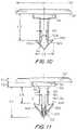
- FIG. 10is a side elevational view of the tissue grip of FIG. 7 ;
- FIG. 11is a side elevational view of the tissue grip of FIG. 10 rotated 90°;
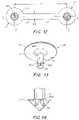
- FIG. 12is a top view of a grip assembly according to one illustrative embodiment
- FIG. 13is a perspective view of a tissue grip according to another illustrative embodiment
- FIG. 14is an enlarged side view of the grip head of FIG. 13 according to one embodiment
- FIG. 15is a side elevational view of a tissue grip according to another illustrative embodiment
- FIG. 16is an enlarged side view of the grip head of FIG. 15 according to one embodiment
- FIG. 17is an enlarged bottom view of the grip head of FIGS. 15-16 according to one embodiment
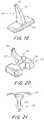
- FIG. 18is a perspective view of a tissue grip with a V-shaped configuration according to another illustrative embodiment
- FIG. 19is a perspective view of a tissue grip with a crescent shaped configuration according to another illustrative embodiment
- FIG. 20is a perspective view of a tissue grip with a claw-like configuration according to another illustrative embodiment
- FIG. 21is a side elevational view of a tissue grip with an arrowhead configuration according to another illustrative embodiment
- FIG. 22is a top view of an implantable prosthesis with a grip arrangement according to one embodiment
- FIG. 23is a top view of an implantable prosthesis with a grip arrangement according to one embodiment
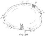
- FIG. 24is a top view of an implantable prosthesis with a grip arrangement according to one embodiment
- FIG. 25is an illustration of a grip arrangement according to another embodiment
- FIG. 26is an illustration of a grip arrangement according to another embodiment
- FIG. 27is an illustration of a grip arrangement according to another embodiment
- FIG. 28is an illustration of a grip arrangement according to another embodiment
- FIG. 29is an illustration of a grip arrangement according to another embodiment
- FIG. 30is an illustration of a grip arrangement according to another embodiment
- FIG. 31is an illustration of a grip arrangement according to another embodiment.
- FIG. 32is an illustration of a grip arrangement according to another embodiment.
- the inventionis directed to an implantable prosthesis for mending an anatomical defect, and is particularly suitable for mending defects in, and weaknesses of, soft tissue and muscle walls or other anatomical regions.
- the phrase “mending a defect”includes acts of repairing, augmenting, and/or reconstructing a defect and/or a potential defect.
- the prosthesisis described below particularly in connection with mending a groin defect including, but not limited to, one or more of an indirect inguinal hernia, a direct inguinal hernia, a femoral hernia and/or other weakness or rupture of the groin anatomy.
- the prosthesisis not so limited and may be employed in other anatomical procedures, as should be apparent to one of skill in the art.
- the prosthesismay be employed for ventral hernias, chest or abdominal wall reconstruction, or large defects, such as those that may occur in obese patients.
- the prosthesismay include one or more features, each independently or in combination, contributing to such attributes.
- the inventionis more particularly directed to a prosthesis which includes a repair fabric having a body portion that is configured to cover or extend across the defect opening or weakness when the body portion is placed against the defect.
- the prosthesismay be in the form of a patch, although the prosthesis may employ other configurations as should be apparent to one of skill in the art.
- the patchmay have a planar or non-planar configuration suitable for a particular procedure employed for mending a defect.
- the prosthesismay be configured with a self-grip arrangement having features that help maintain the position of the prosthesis relative to the defect.
- the self-grip arrangementmay reduce, if not eliminate, separation, sliding, twisting, folding and/or other movement, as may be desired, between the prosthesis and adjacent tissue. Such an arrangement may also reduce, if not eliminate, the need for a surgeon to suture, staple, tack, or otherwise provisionally anchor the prosthesis in place pending tissue integration.
- the prosthesismay include a plurality of grips protruding from the body portion. More particularly, the grips may protrude from a surface of the body portion that is configured to engage adjacent tissue. The grips may be configured to penetrate and grip the tissue when the prosthesis is placed and/or pressed against it. In this manner, the grips may be configured to protrude a defined distance from the surface of the body portion to penetrate a depth of tissue sufficient to provide the desired amount of grip.
- the gripsmay be arranged on the body portion in any suitable configuration to provide a desired amount of grip as should be apparent to one of skill in the art.
- the gripsmay be distributed across the body portion in a uniform, non-uniform or random array, and/or any suitable combination of arrays.
- the gripsmay be distributed across the entire body portion or located at one or more select regions of the body portion.
- the gripsmay be located at one or more select regions adjacent one or more segments of the outer periphery of the body portion, and/or one or more select regions located within the inner region of the body portion inwardly away from the outer periphery.
- Each select regionmay include one or more grips arranged in any suitable pattern within the region.
- One or more of the select regionsmay employ the same or different arrangements of grips relative to one or more other select regions of grips.
- the gripsmay be fabricated independent of and mounted to the body portion of the prosthesis.
- the gripsmay be formed from a material that is different from the body portion.
- the gripsmay be formed of a bioabsorbable material, while the body portion may be formed of a non-absorbable material.
- Such an arrangementmay provide the prosthesis with temporary grip properties during the period of tissue integration, while reducing the amount of foreign material that remains present in a patient's body and maintaining long-term strength of the prosthesis.
- the prosthesismay include grips having the same or different grip configurations and/or arrangements depending on a particular application of the prosthesis.
- the prosthesismay include grips having the same shape, but mounted in different orientations relative to each other on the body portion.
- the prosthesismay include grips with one or more different shapes in one or more regions of the body portion. In this manner, the prosthesis may be provided with various grip characteristics based on the particular orientations and/or shapes of the grips individually and as a whole.
- the gripsmay be directly or indirectly mounted to the body portion of the prosthesis.
- Each gripmay include a base and a grip body extending from the base.
- the basemay be mounted to the body portion with the grip body protruding from the body portion and configured to penetrate and grip tissue.
- the gripsmay be molded or welded directly to the body portion.
- each gripmay be insert molded to prefabricated mesh fabric placed within a mold that receives grip material and forms the desired shape of the grip directly onto the body portion.
- each gripmay be mechanically mounted to the body portion.
- each gripmay be mounted using a mechanical component or arrangement that is attached to the body portion.
- the body portionmay include a first layer of repair fabric and a second layer of repair fabric attached to the first layer to secure the grips to the first layer.
- the base of each gripmay be retained between the first and second layers of repair fabric.
- each gripmay be mounted directly to the second layer which is subsequently attached to the first layer.
- Such indirect mounting arrangementsmay reduce the likelihood of potential degradation of the strength and/or tissue infiltration characteristics of the first layer.
- the base of each gripmay be configured to mechanically connect with the repair fabric of the body portion.
- the gripmay include a grip head located at the end of the grip body opposite the base that is configured for insertion into tissue while providing a sufficient amount of tissue grip to reduce, if not eliminate, inadvertent release from the tissue.
- the grip headmay also be configured to minimize, if not eliminate, potential entanglement with the prosthesis, such as a mesh repair fabric, while providing desired tissue grip.
- the grip headmay include one or more barbs of any suitable configuration as should be apparent to one of skill in the art.
- the grip headmay include barbs having different configuration relative to each other.
- a first barb configurationmay be suitable for tissue grip while minimizing entanglement and a second barb configuration may be suitable for just gripping tissue.
- the grip head configurationsmay include, but are not be limited to, an arrowhead shape, a crescent shape, multiple prongs arranged in a V-shape, and a claw shape. Other grip head configurations are also contemplated.
- the prosthesismay be used for mending soft tissue and muscle wall defects using various surgical techniques, including open, laparoscopic, hybrid (e.g., Kugel procedure), and robotic techniques.
- open proceduresthe prosthesis may be placed through a relatively large incision made in the abdominal wall and layers of tissue and then the defect is filled or covered with the repair fabric.
- laparoscopic and hybrid proceduresthe prosthesis may be collapsed, such as by rolling or folding, into a reduced configuration for entry into a subject, either directly through a comparatively smaller incision or through a slender laparoscopic cannula that is placed through the incision.
- the prosthesismay have particular application with robotic procedures in which placement of the prosthesis is achieved using surgical robotic tools which may involve passage of the prosthesis through a relatively small cannula (e.g., 8 mm) as compared to a cannula (e.g., 10-12 mm) typically employed for more conventional laparoscopic techniques.
- a relatively small cannulae.g. 8 mm
- a cannulae.g., 10-12 mm
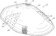
- FIGS. 1-4illustrate one embodiment of a prosthesis for mending tissue and muscle wall defects, such as a hernia defect.
- the prosthesisincludes a repair fabric of implantable, biologically compatible material.
- the repair fabricmay comprise a mesh fabric that is relatively flexible, thin and light weight and meets the performance and physical characteristics for mending soft tissue and muscle wall defects.
- the prosthesis 20may include a body portion 22 configured with a size and/or shape suitable to cover or extend across the defect opening or weakness when the body portion is placed against the defect.
- the prosthesismay also include a plurality of grips 24 protruding from the body portion to provide a self-grip arrangement for maintaining the position of the prosthesis relative to the defect.
- the grips 24are configured to protrude from a surface 25 of the body portion for engaging adjacent tissue.
- the grips 24may be configured to penetrate and grip the tissue when the prosthesis is placed and/or pressed against it. In this manner, the grips may be configured to protrude a defined distance from the surface of the body portion to penetrate a depth of tissue sufficient to provide the desired amount of grip. In one embodiment, the grips 24 may be configured to protrude 0.05 inches to 0.15 inches from the surface. However, the grips may be configured to protrude other distances sufficient to provide a desired amount of grip as should be apparent to one of skill in the art.
- the grips 24may be located at one or more grip regions 26 of the body portion. Such an arrangement may be suitable for placing grips in selected regions of the body portion to accommodate a particular anatomical region. For example, it may be desirable to avoid providing grips on regions of the body portion that may potentially contact vessels, nerves or other portions of the anatomy at the defect site as should be apparent to one of skill in the art.
- the grip regions 26may be located adjacent one or more segments of the outer periphery 28 of the body portion 22 and extend inwardly toward the inner region of the body portion.
- Each grip region 26may include a plurality of grips 24 arranged in any suitable pattern within the region, for example, to facilitate rolling and/or folding of the prosthesis to the site of the soft tissue repair.
- the prosthesis 20may be provided with three grip regions 26 including grips 24 arranged in multiple rows and/or columns with the number of grips in each row and/or column decreasing in a direction away from the outer periphery.
- each grip region 26may include ten grips 24 arranged in four rows and/or columns of decreasing grips. In this manner, the grips may be viewed as having a generally triangular arrangement.
- any suitable grip arrangementmay be provided on the prosthesis to provide a desired amount of grip as should be apparent to one of skill in the art.
- a single row of gripsmay be located along one or more select segments of the outer periphery.
- one or more of the select regionsmay employ the same or different arrangements of grips relative to one or more other select regions of grips.
- the gripsmay be arranged in a uniform, non-uniform or random array, and/or any suitable combination of arrays. Rather than limited to one or more select grip regions, the grips may be distributed across the entire body portion.
- the gripsmay be fabricated independent of and mounted to the body portion of the prosthesis. Independent fabrication of the grips may provide flexibility for configuring the prosthesis.
- the gripsmay be formed of a bioabsorbable material, while the body portion may be formed of a non-absorbable material.
- Such an arrangementmay provide the prosthesis with temporary grip properties during the period of tissue integration, while reducing the amount of foreign material that remains present in a patient's body and maintaining long-term strength of the prosthesis.
- the prosthesismay include grips having the same or different grip configurations and/or arrangements depending on a particular application of the prosthesis.
- the prosthesismay include grips having the same shape, but mounted in different orientations relative to each other on the body portion.
- the prosthesismay include grips with one or more different shapes in one or more regions of the body portion. In this manner, the prosthesis may be provided with various grip characteristics based on the particular orientations and/or shapes of the grips individually and as a whole.
- each grip 24may include a base 30 and a grip body 32 extending from the grip base.
- the grip base 30may be mounted to the body portion 22 of the prosthesis with the grip body 32 protruding from the body portion to penetrate and grip tissue.
- the body portion 22 of the prosthesismay include a first layer 34 of repair fabric configured to extend across and cover the defect and a second layer 36 of repair fabric attached to the first layer to secure each grip to the first layer.
- the base 30 of each gripmay be retained between the first and second layers 34 , 36 of repair fabric with the second layer 36 acting as a backing layer.
- the grip body 32may extend through a pore 38 of the first layer 34 of fabric, although the prosthesis is not so limited.
- each backing layer 36may be configured to correspond with the shape of each grip region 26 of the prosthesis.
- the shape of the backing layeris not so limited and may have any suitable configuration apparent to one of skill in the art.
- Each backing layer 36may be attached to the first layer 34 using any suitable fastening arrangement as should be apparent to one of skill in the art.
- the backing layers 36may be attached to the first layer 34 using stitches 40 extending about the outer periphery 42 of the backing layer. Additional stitches may be placed between rows and/or columns of the grips to reduce billowing of the backing layer and maintain the grips in position between the layers. It is to be appreciated that other attachment techniques may be employed including, but not limited to, bonding and ultrasonic welding.
- Such an arrangementmay be desirable to allow one or more grip regions of any desired configuration be trimmed from a relatively large layer of fabric having pre-attached grips. Such an indirect mounting arrangement may also reduce the incidence of potential degradation of the strength and/or tissue infiltration characteristics of the first layer.
- each grip 24may be mounted directly to the second layer 36 of fabric which is subsequently attached to the first layer 34 of fabric.
- the grip base 30may be secured to the second layer 36 with the grip body 32 extending through the second layer.
- the grip basemay be attached to the second layer using any suitable technique including, but not limited to, bonding or ultrasonic welding 44 .
- the second layermay be attached to the first layer using any suitable fastening technique as described above.
- each gripmay be insert molded to prefabricated mesh fabric placed within a mold that receives grip material and forms the desired shape of the grip directly onto the mesh fabric.
- the mesh fabricmay be used as the first layer 34 of the body portion or as the second layer 36 of the body portion that is attached to the first layer.
- the base 30 of each grip 24may be configured to mechanically connect with the repair fabric of the body portion.
- the prosthesismay include grips 24 having the same or different grip configurations and/or arrangements depending on a particular application of the prosthesis.
- the grip 24may include a grip head 50 located at the end of the grip body 32 opposite the base 30 .
- the grip head 50may be configured for insertion into tissue while providing a sufficient amount of tissue grip to reduce, if not eliminate, inadvertent release from the tissue.
- the grip headmay include one or more barbs configured to penetrate tissue and resist withdrawal of the grip from the tissue.
- the grip head 50may include four barbs 52 a , 52 b located at 90° positions about the end of the grip body.
- the grip headmay employ a cruciform configuration with a first pair of barbs 52 a located along a first axis Y and a second pair of barbs 52 b located along a second axis X. Such an arrangement may provide omnidirectional sliding resistance.
- the gripmay include any number and location of barbs as should be apparent to one of skill in the art.
- the grip headmay include a first pair of barbs 52 a located at a first distance L 2 along the grip body and a second pair of barbs 52 b located at a second distance L 3 along the grip body which is different from the first distance.
- any number of barbsmay be located at different locations along the barb body as should be apparent to one of skill in the art.
- the gripmay include a grip locator 54 configured for insertion into a pore 38 or other opening in the first or second layer of repair fabric.
- the size and/or shape of the grip locatormay be selected to correspond to the pores of the repair fabric.
- the grip locator 54may be configured as a boss protruding from the grip base 30 with the grip body extending from the locator.
- the grip locator 54may protrude from a central region of the grip base, although other arrangements are contemplated.
- the grip locator 54may have a cylindrical shape, although other shapes are contemplated.
- the grip locator 54may have a conical or frusto-conical shape.
- the grip locator 54may be tapered to decrease in size in a direction from the grip base 30 toward the grip body 32 . Such an arrangement may facilitate insertion of the tissue grip into a pore 38 or other opening of the repair fabric. It should be understood, however, that the grip locator, if provided, may employ any suitable configuration as should be apparent to one of skill in the art.
- the grip base 30may have a diameter D 1 of about 0.125 inches with a thickness T 1 of about 0.01 inches.
- the grip locatormay have a diameter D 2 of about 0.05 inches with a thickness T 2 of about 0.01 inches.
- the grip bodymay have a length L 1 of about 0.08 inches extending from the surface of the grip base and a diameter D 3 of about 0.02 inches to about 0.035 inches.
- the grip headmay include a first pair of barbs 52 a with a grip surface 56 a located a distance L 2 of about 0.06 inches from the grip base and a second pair of barbs 52 b with a grip surface 56 b located a distance L 3 of about 0.047 to about 0.05 inches from the grip base.
- the first pair of barbs 52 amay have an outer diameter D 4 of about 0.04 inches and the second pair of barbs 52 b may have an outer diameter D 5 of about 0.044 inches.
- the first pair of barbs 52 amay have a width W 1 of about 0.006 inches and the second pair of barbs 52 b may have a width W 2 about 0.01 inches.
- each gripmay be fabricated as a single grip that is attached to the body portion of the prosthesis.
- itmay be desirable to fabricate and provide multiple interconnected grips for attachment to the body portion.
- a grip arrangement including multiple gripsmay facilitate handling and assembly of the grips to the body portion in contrast to the smaller size of a single grip.
- a grip assembly 60may include two (as shown) or more grips 24 connected together with an elongated coupling 62 extending therebetween.
- the grip assemblymay be fabricated as a unitary component.
- the grip assemblymay be a molded component fabricated from the same material.
- the grip assemblymay be fabricated using any suitable process and may include multiple materials depending on the particular characteristics desired for the grips.
- the couplingmay be configured to provide a desired amount of support for handling the grips while also having a sufficient amount of flexibility to minimize any potential increase in the stiffness of the body portion.
- the coupling 62may have a thickness that corresponds to the thickness of the grip base 30 of the grips.
- the coupling 62may be configured with a width W 3 of about 0.04 inches.
- the grips 24may be configured with a center-to-center spacing L 4 of about 0.38 inches. It is to be understood that any suitable coupling arrangement and grip spacing may be utilized as should be apparent to one of skill in the art.
- FIGS. 13-14illustrate one embodiment of such an arrangement.
- the grip head 50may be utilized for a single grip, as illustrated in FIG. 13 , or on each grip of a grip assembly, such as the grip assembly described above.
- a grip headconfigured to reduce, if not eliminate, potential mesh entanglement during handling and/or delivery of the prosthesis.
- the gripsWhen collapsed, at least some of the grips may be placed into engagement with other portions of the prosthesis which could potentially lead to a grip becoming entangled with the prosthesis, particularly when the prosthesis is fabricated from a mesh fabric. Such entanglement may make it more difficult and require additional time for a surgeon to open the collapsed prosthesis after delivery to the surgical site.
- the prosthesismay include grips 24 having a grip head 50 configured to grip tissue while also minimizing potential entanglement with the prosthesis.
- the grip headmay include one or more primary barbs 52 a configured to both grip tissue and minimize, if not eliminate, potential entanglement with the prosthesis.
- the grip headmay also include one or more secondary barbs 52 b configured solely to grip tissue. In this manner, the secondary barbs may enhance the grip of the barbs by providing additional traction while the primary barbs minimize potential entanglement.
- the primary barbs 52 amay be configured and arranged to shield the secondary barbs 52 b from entanglement with the prosthesis while allowing the secondary barbs to grip tissue.
- the secondary barbs 52 bmay be smaller in size as compared to the primary barbs 52 a .
- the grip head 50may include four primary barbs 52 a located along axes X, Y positioned 90° apart and four secondary barbs 52 b located along axes X′, Y′ positioned 90° apart with the primary barbs being offset from the secondary barbs by about 45°.
- each secondary barb 52 bmay be located between a pair of primary barbs 52 a to minimize, if not prevent, engagement between the secondary barbs and the prosthesis, such as the filaments of a mesh prosthesis.
- the grip head 50may employ any number of primary barbs and/or secondary barbs positioned in any suitable arrangement as should be apparent to one of skill in the art.
- the primary grip 52 amay include a first grip surface 56 a to grip tissue when placed against tissue while allowing the grip head 50 to release from the prosthetic material, such as mesh fabric, when placed against the prosthesis.
- the first grip surface 56 amay be configured with a ramp-like structure from which filaments of the prosthesis may be slid off and away from the grip head as the grip is being pulled away from the prosthesis.
- the first grip surfacemay be angled to slope inwardly from the outer tip 58 a of the primary barb toward the grip body 32 and in a direction toward the grip base 30 . In this manner, the first grip surface 56 a may be oriented at an angle A so that filaments of the prosthesis located along the length of the grip body may be guided along the grip surface and off the grip head as the grip is pulled from the prosthesis.
- the first grip surface 56 amay be oriented at an angle A of 30° relative to a plane P perpendicular to the longitudinal axis Z of the grip.
- other angles suitable for tissue grip and grip head release from the prosthesismay be employed as should be apparent to one of skill in the art.
- varying the first grip surface anglemay adjust the amount of tissue grip and grip head release. For example, a relatively large grip surface angle may enhance grip head release while reducing the amount of tissue grip, while a relatively small grip surface angle may reduce grip head release while increasing the amount of tissue grip.
- the secondary grip 52 bmay include a second grip surface 56 b configured to grip tissue when placed against tissue.
- the second grip surfacemay have a relatively flat configuration.
- the second grip surface 56 bmay be oriented perpendicular to the longitudinal axis Z of the grip to provide a relatively higher degree of tissue grip as compared to the first grip surface 56 a .
- other angles suitable for tissue gripmay be employed as should be apparent to one of skill in the art. In this manner, varying the angle of the secondary grip surface may adjust the amount of tissue grip desired for the grip head.
- the first grip surface 56 amay be angled from the plane P of the second grip surface 56 b .
- the outer tips 58 a of the primary grips 52 a and the outer tips 58 b of the secondary grips 52 bmay be coplanar.
- the outer tip 58 a of the primary grip 52 amay be located in a plane offset from the tip 58 b of the secondary grip 52 b.
- the primary grips 52 amay be configured to shield the secondary grips 52 b in a manner to minimize entanglement of the secondary grips with the prosthesis.
- the first grip surface 56 amay be located between the second grip surface 56 b and the grip base 30 .
- the tips 58 a of the primary grips 52 amay extend in an outward radial direction from the grip body 32 a distance which is greater than the tips 58 b of the secondary grips 52 b .
- features of the prosthesissuch as filaments of a mesh fabric, may be guided by the first grip surface in the outward radial direction away from the grip body and beyond the tip 58 b of the secondary grip so that the filaments are guided around the secondary grips as the grip is pulled from the prosthesis.
- the outer tips 58 a of the first gripsmay be positioned along a circular diameter D 6 of 0.042 in and the outer tips 58 b of the secondary tips may be positioned along a circular diameter D 7 of 0.031 in.
- other arrangements of the outer tips of the barbs of the grip headmay be employed as should be appreciated by one of skill in the art.
- the grip head 50may be utilized for a single grip, as illustrated in FIG. 15 , or on each grip of a grip assembly, such as the grip assembly described above.
- the tissue gripmay employ various configurations to provide a desired amount of grip for holding the prosthesis in place against tissue.
- the grip described abovemay be considered as having a cruciform configuration. Examples of other non-limiting grip configurations are described below in connection with FIGS. 18-21 .
- FIG. 18illustrates an embodiment of a grip having a multi-prong configuration.
- the grip body 32may include a pair of prongs 70 extending from the grip base 30 .
- the prongs 70may be arranged in a V-shaped configuration for penetration into tissue.
- FIG. 19illustrates an embodiment of a grip having a crescent configuration.
- the grip body 32may have a crescent shape extending from the grip base 30 .
- the grip body 32decreases in size in a direction from the base 30 toward its tip 72 for penetration into tissue.
- FIG. 20illustrates an embodiment of a grip having a claw-like configuration.
- the grip body 32employ a C-shaped configuration with a pair of tips 74 for penetrating tissue.
- the grip body 32may be oriented relative to the grip base 30 with the tips extending in a direction away from the grip base.
- FIG. 21illustrates an embodiment of a grip having an arrowhead configuration.
- the grip body 32extends from the grip base 30 .
- the grip body 32include an arrowhead with a pair of oppositely extending barbs for penetrating and gripping tissue.
- the body portion 22may be a preformed, non-planar patch with a 3-dimensional curved shape.
- the body portion 22may have a shape corresponding to the 3DMAX Light Mesh or 3DMAX Mesh, available from C.R. Bard, and described in one or more of U.S. Pat. Nos. 6,723,133, 6,740,122 and 6,740,122.
- the prosthesismay be particularly suited for fitting and mending defects to the inguinal anatomy.
- the prosthesismay employ other configurations as should be apparent to one of skill in the art.
- the patchmay have planar or other non-planar configurations suitable for a particular procedure employed for mending a defect.
- the prosthesismay be provided as a planar sheet of self-gripping repair fabric that may be selectively trimmed by a surgeon to any desired size and shape for the particular procedure.
- the prosthesismay employ any arrangement of grips to provide a desired amount of grip and traction for a particular application.
- FIG. 22illustrates an embodiment of a 3D curved prosthesis 20 including four separate grip regions 26 , as compared to three grip regions as shown in FIGS. 1-4 , located in proximity to the outer periphery 28 of the body portion 22 .
- each group or grip region 26may include multiple rows and/or columns of grips 24 .
- FIG. 23illustrates an embodiment of a 3D curved prosthesis 20 including three separate grip regions 26 located in proximity to the outer periphery 28 of the body portion 22 .
- a pair of grip regionsmay be located on upper medial and lateral portions of the prosthesis, and a grip region may be located on a lower medial portion of the prosthesis.
- each group or grip region 26may include multiple rows and/or columns of grips 24 .
- Each grip region on the upper medial and lateral portionsmay have a semi-annular periphery.
- the grip region on the lower medial portionmay have a triangular periphery.
- FIG. 24illustrates an embodiment of a 3D curved prosthesis 20 including separate groups of grips 24 located along the outer periphery 28 of the body portion 22 . As shown, each group or grip region 26 may include a single row of grips 24 .
- FIG. 25illustrates an embodiment of a layer of repair fabric including grips 24 uniformly distributed across the fabric.
- the fabricmay be preformed into a configuration for use as a prosthesis or may be selectively trimmed into a desirable configuration for use as a prosthesis or a portion of a prosthesis, such as a second layer described above.
- the gripsmay be mounted to the fabric in at least two different orientations to provide a desired grip or traction properties for the prosthesis.
- the prosthesismay include grips, such as the grips illustrated in FIGS. 18-21 , which individually provide bidirectional traction. Mounting the grips in alternating 90° orientations may provide omnidirectional traction for the prosthesis. The particular spacing and orientation may be selected to provide the desired grip and/or traction.
- the repair fabricmay employ a knit construction that provides openings or pores to allow tissue infiltration to incorporate the prosthesis.
- the repair fabricmay also have sufficient flexibility to promote an easy reduction in size for entry into the subject. In this manner, the flexible fabric may be collapsed into a slender configuration, such as a roll, which can be supported in, and advanced through, a narrow laparoscopic cannula for use in laparoscopic or robotic procedures.
- the prosthesis 20may be formed from one or more layers of knitted mesh fabric.
- the meshWhen implanted, the mesh promotes rapid tissue or muscle ingrowth into and around the mesh structure.
- surgical materialswhich may be utilized for the layers and are suitable for tissue or muscle reinforcement and defect correction include, but are limited to, BARD Mesh (available from C.R. Bard, Inc.), BARD Soft Mesh (available from C.R. Bard, Inc.), SOFT TISSUE PATCH (microporous ePTFE—available from W.L.
- mesh materialse.g., available from Atrium Medical Corporation.
- Absorbable or resorbable materialsincluding PHASIX Mesh (available from C.R. Bard, Inc.), polyglactin (VICRYL—available from Ethicon, Inc.) and polyglycolic acid (DEXON—available from US Surgical, Inc.), may be suitable for applications involving temporary correction of tissue or muscle defects.
- Collagen materialssuch as COOK SURGISIS, available from Cook Biomedical, Inc. may also be used.
- the mesh fabricmay be formed from multifilament yarns and that any suitable method, such as knitting, weaving, braiding, molding and the like, may be employed to form the mesh material.
- the gripsmay be formed of a resorbable material.
- the gripsprovide a desired level of tissue grip for initial placement and positioning of the prosthesis.
- the gripseventually become rebsorbed by the body at which time the prosthesis has become sufficiently integrated with the tissue.
- rebsorbable materialsinclude, but are not limited to, PLG (L-lactide/glycolide) or PLA (polylactic acid) polymers.
- PLGL-lactide/glycolide
- PLApolylactic acid
- An example of non-rebsorbable material which may be utilized for the gripsincludes, but is not limited to, polypropylene. It is to be appreciated that other suitable biocompatible materials, resorbable or non-resorbable, may be used for the grips as should be apparent to one of skill in the art.
- the gripsmay be fabricated using an injection molding process.
- any suitable manufacturing processmay be used to fabricate the grips as should be apparent to one of skill in the art.
- the gripsmay be fabricated using 3D printing and machining processes.
- Traction forcewas evaluated for various grip arrangements and compared to a known mesh fabric. Testing methodology is described below with results provided in Table 1. The average results are reported from testing ten samples of each configuration.
- the porcine tissue couponmeasured 2.7 inches ⁇ 3.5 inches with a minimum thickness of 0.25 inches.
- An approximately 1 inch ⁇ 1 inch test sample (unless indicated otherwise below) of a self-gripping mesh configurationwas placed, barb side down, on top of and centered on the porcine tissue sample.
- a free weightwas set on top of the mesh sample for about 3 seconds and then removed. The free weight was approximately 1 lb to 3 lb.
- the mesh samplewas allowed to rest/settle on the porcine tissue sample, at room temperature, undisturbed for 1 minute before initiating the test.
- a traction forcewas applied to the mesh in a single direction along the plane defined by the contact area between the mesh sample and the porcine tissue sample.
- the meshwas oriented so that the grips were pulled in the direction of the barbs or other grip features. The procedure was repeated for ten mesh samples of the same configuration.
- Test sampleswere provided with different grip configurations and arrangements of grips.
- the grip arrangements of the test samplesare illustrated in FIGS. 26-31 .
- the direction of applied forceis shown as arrow F.
- FIG. 26illustrates a grip arrangement including grips located every other space and every other row. This arrangement was tested for grip configurations illustrated in FIGS. 18-21 .
- FIG. 27illustrates a grip arrangement including grips located every other space and every row. This arrangement was tested for grip configurations illustrated in FIGS. 18-21 .
- FIG. 28illustrates a grip arrangement including grips positioned in a 5 ⁇ 5 square. This arrangement was tested for grip configurations illustrated in FIGS. 18-21 .
- FIG. 29illustrates a grip arrangement including grips positioned in a 4 ⁇ 4 square. This arrangement was tested for the grip configuration illustrated in FIG. 21 .
- FIG. 30illustrates a grip arrangement including grips located in two rows with four grips provided in one row and three grips provided in the other row. This arrangement was tested for the grip configuration illustrated in FIG. 21 .
- FIG. 31illustrates a grip arrangement including grips located in two rows with eight grips provided in each row. This arrangement was tested for grip configurations illustrated in FIGS. 18-21 .
- FIG. 32illustrates a grip arrangement including seven grip arrays located in three rows with three arrays provided in a center row flanked by rows with two arrays.
- the grip arrayswere located within a test sample area of approximately 1.7 inches ⁇ 0.8 inches.
- Each arrayincludes three grips for a total of twenty-one grips with nine grips located along the central row and six grips located along each row flanking the center row. This arrangement was tested for the grip configuration illustrated in FIGS. 15-17 . This arrangement provided an average traction force of 0.68 lbf.
- the grip configurationsare referred to as Grip A ( FIG. 18 ), Grip B ( FIG. 19 ), Grip C ( FIG. 20 ) and Grip D ( FIG. 21 ).
- the grip arrangementsare referred to as Arrangement 1 ( FIG. 26 ), Arrangement 2 ( FIG. 27 ), Arrangement 3 ( FIG. 28 ), Arrangement 4 ( FIG. 29 ), Arrangement 5 ( FIG. 30 ), and Arrangement 6 ( FIG. 31 ).
Landscapes
- Health & Medical Sciences (AREA)
- Cardiology (AREA)
- Oral & Maxillofacial Surgery (AREA)
- Transplantation (AREA)
- Engineering & Computer Science (AREA)
- Biomedical Technology (AREA)
- Heart & Thoracic Surgery (AREA)
- Vascular Medicine (AREA)
- Life Sciences & Earth Sciences (AREA)
- Animal Behavior & Ethology (AREA)
- General Health & Medical Sciences (AREA)
- Public Health (AREA)
- Veterinary Medicine (AREA)
- Prostheses (AREA)
Abstract
Description
| TABLE 1 | |||
| Test Sample | Average Traction Force (psi) | ||
| Covidien ProGrip Mesh | 0.275 | ||
| Grip A, Arrangement 1 | 0.285 | ||
| Grip A, Arrangement 2 | 0.335 | ||
| Grip B, Arrangement 1 | 0.3 | ||
| Grip B, Arrangement 2 | 0.26 | ||
| Grip C, Arrangement 1 | 0.285 | ||
| Grip C, Arrangement 2 | 0.39 | ||
| Grip A, Arrangement 3 | 0.335 | ||
| Grip B, Arrangement 3 | 0.21 | ||
| Grip C, Arrangement 3 | 0.315 | ||
| Grip D, | 0.49 | ||
| Grip D, | 0.32 | ||
| Grip A, Arrangement 6 | 0.335 | ||
| Grip B, Arrangement 6 | 0.365 | ||
| Grip C, Arrangement 6 | 0.415 | ||
| Grip D, Arrangement 6 | 0.365 | ||
Claims (30)
Priority Applications (2)
| Application Number | Priority Date | Filing Date | Title |
|---|---|---|---|
| US16/165,436US11458004B2 (en) | 2017-10-19 | 2018-10-19 | Self-gripping hernia prosthesis |
| US17/872,384US12402996B2 (en) | 2017-10-19 | 2022-07-25 | Self-gripping hernia prosthesis |
Applications Claiming Priority (2)
| Application Number | Priority Date | Filing Date | Title |
|---|---|---|---|
| US201762574525P | 2017-10-19 | 2017-10-19 | |
| US16/165,436US11458004B2 (en) | 2017-10-19 | 2018-10-19 | Self-gripping hernia prosthesis |
Related Child Applications (1)
| Application Number | Title | Priority Date | Filing Date |
|---|---|---|---|
| US17/872,384DivisionUS12402996B2 (en) | 2017-10-19 | 2022-07-25 | Self-gripping hernia prosthesis |
Publications (2)
| Publication Number | Publication Date |
|---|---|
| US20190117363A1 US20190117363A1 (en) | 2019-04-25 |
| US11458004B2true US11458004B2 (en) | 2022-10-04 |
Family
ID=64277791
Family Applications (2)
| Application Number | Title | Priority Date | Filing Date |
|---|---|---|---|
| US16/165,436Active2039-01-26US11458004B2 (en) | 2017-10-19 | 2018-10-19 | Self-gripping hernia prosthesis |
| US17/872,384Active2038-12-27US12402996B2 (en) | 2017-10-19 | 2022-07-25 | Self-gripping hernia prosthesis |
Family Applications After (1)
| Application Number | Title | Priority Date | Filing Date |
|---|---|---|---|
| US17/872,384Active2038-12-27US12402996B2 (en) | 2017-10-19 | 2022-07-25 | Self-gripping hernia prosthesis |
Country Status (6)
| Country | Link |
|---|---|
| US (2) | US11458004B2 (en) |
| EP (1) | EP3697338A1 (en) |
| CN (1) | CN111432749B (en) |
| AU (1) | AU2018351351B2 (en) |
| CA (1) | CA3079532A1 (en) |
| WO (1) | WO2019079709A1 (en) |
Families Citing this family (3)
| Publication number | Priority date | Publication date | Assignee | Title |
|---|---|---|---|---|
| US10842603B1 (en)* | 2017-10-16 | 2020-11-24 | David Lee Street | Sutureless ventral hernia meshing system and method of fixation |
| CN111432749B (en) | 2017-10-19 | 2023-04-04 | C.R.巴德公司 | Self-gripping hernia prosthesis |
| US12064330B2 (en) | 2020-04-28 | 2024-08-20 | Covidien Lp | Implantable prothesis for minimally invasive hernia repair |
Citations (215)
| Publication number | Priority date | Publication date | Assignee | Title |
|---|---|---|---|---|
| US3054406A (en) | 1958-10-17 | 1962-09-18 | Phillips Petroleum Co | Surgical mesh |
| US3124136A (en) | 1964-03-10 | Method of repairing body tissue | ||
| US3320649A (en) | 1962-10-23 | 1967-05-23 | Naimer Jack | Methods of making separable fastening fabrics |
| US3494006A (en) | 1968-01-12 | 1970-02-10 | George C Brumlik | Self-gripping fastening device |
| US3981051A (en) | 1970-03-16 | 1976-09-21 | Brumlik George C | Bristle-like gripping device |
| US4169303A (en) | 1976-11-24 | 1979-10-02 | Lemelson Jerome H | Fastening materials |
| US4338800A (en) | 1979-05-09 | 1982-07-13 | Yoshida Kogyo K.K. | Velvet-type fastener web |
| US4347847A (en) | 1980-06-06 | 1982-09-07 | Usher Francis C | Method of hernia repair |
| US4452245A (en) | 1980-06-06 | 1984-06-05 | Usher Francis C | Surgical mesh and method |
| US4520821A (en) | 1982-04-30 | 1985-06-04 | The Regents Of The University Of California | Growing of long-term biological tissue correction structures in vivo |
| US4653486A (en)* | 1984-04-12 | 1987-03-31 | Coker Tom P | Fastener, particularly suited for orthopedic use |
| EP0276890A2 (en) | 1987-01-30 | 1988-08-03 | AUSONIA S.p.A. | Textile manufactured article for contact fastener, and method and equipment for its production |
| US4976728A (en) | 1988-03-29 | 1990-12-11 | Sulzer Brothers Limited | Reinforcement for a bone cement bed |
| US5019096A (en) | 1988-02-11 | 1991-05-28 | Trustees Of Columbia University In The City Of New York | Infection-resistant compositions, medical devices and surfaces and methods for preparing and using same |
| US5032122A (en) | 1987-04-24 | 1991-07-16 | The Procter & Gamble Company | Loop fastening material for fastening device and method of making same |
| US5116357A (en) | 1990-10-11 | 1992-05-26 | Eberbach Mark A | Hernia plug and introducer apparatus |
| US5147374A (en) | 1991-12-05 | 1992-09-15 | Alfredo Fernandez | Prosthetic mesh patch for hernia repair |
| US5176692A (en) | 1991-12-09 | 1993-01-05 | Wilk Peter J | Method and surgical instrument for repairing hernia |
| US5234488A (en) | 1987-10-19 | 1993-08-10 | Shinagawa Refractories Co., Ltd. | Mold additive for continuous casting of steel |
| US5254127A (en) | 1992-02-28 | 1993-10-19 | Shadyside Hospital | Method and apparatus for connecting and closing severed blood vessels |
| US5254133A (en) | 1991-04-24 | 1993-10-19 | Seid Arnold S | Surgical implantation device and related method of use |
| US5258000A (en) | 1991-11-25 | 1993-11-02 | Cook Incorporated | Tissue aperture repair device |
| US5330445A (en) | 1988-05-26 | 1994-07-19 | Haaga John R | Sheath for wound closure caused by a medical tubular device |
| US5356432A (en) | 1993-02-05 | 1994-10-18 | C. R. Bard, Inc. | Implantable mesh prosthesis and method for repairing muscle or tissue wall defects |
| US5378522A (en) | 1992-07-06 | 1995-01-03 | Lagomarsino; Rich | Ready wrap |
| US5383897A (en) | 1992-10-19 | 1995-01-24 | Shadyside Hospital | Method and apparatus for closing blood vessel punctures |
| FR2712177A1 (en) | 1993-11-08 | 1995-05-19 | Sgro Jean Claude | Prosthetic element esp. vascular or parietal implant |
| US5569273A (en) | 1995-07-13 | 1996-10-29 | C. R. Bard, Inc. | Surgical mesh fabric |
| US5634931A (en) | 1994-09-29 | 1997-06-03 | Surgical Sense, Inc. | Hernia mesh patches and methods of their use |
| US5643295A (en) | 1994-12-29 | 1997-07-01 | Yoon; Inbae | Methods and apparatus for suturing tissue |
| US5716409A (en) | 1996-10-16 | 1998-02-10 | Debbas; Elie | Reinforcement sheet for use in surgical repair |
| US5716408A (en) | 1996-05-31 | 1998-02-10 | C.R. Bard, Inc. | Prosthesis for hernia repair and soft tissue reconstruction |
| US5761775A (en) | 1996-10-17 | 1998-06-09 | Legome; Mark J. | Mushroom and loop material closure system for high shear strength and low peel strength applications |
| US5769864A (en) | 1994-09-29 | 1998-06-23 | Surgical Sense, Inc. | Hernia mesh patch |
| US5836961A (en) | 1992-06-02 | 1998-11-17 | General Surgical Innovations, Inc. | Apparatus and method for developing an anatomic space for laparoscopic hernia repair and patch for use therewith |
| US5906617A (en) | 1997-08-15 | 1999-05-25 | Meislin; Robert J. | Surgical repair with hook-and-loop fastener |
| US5916225A (en) | 1994-09-29 | 1999-06-29 | Surgical Sense, Inc. | Hernia mesh patch |
| DE19832634A1 (en) | 1998-07-09 | 2000-01-13 | Ethicon Endo Surgery Europe | Multilayer flat implant especially for hernia treatment |
| US6042534A (en) | 1997-02-13 | 2000-03-28 | Scimed Life Systems, Inc. | Stabilization sling for use in minimally invasive pelvic surgery |
| US6090116A (en) | 1997-10-03 | 2000-07-18 | D'aversa; Margaret M. | Knitted surgical mesh |
| US6176863B1 (en) | 1994-09-29 | 2001-01-23 | Bard Asdi Inc. | Hernia mesh patch with I-shaped filament |
| US6241747B1 (en)* | 1993-05-03 | 2001-06-05 | Quill Medical, Inc. | Barbed Bodily tissue connector |
| US20010010023A1 (en)* | 1999-06-04 | 2001-07-26 | Schwartz Robert E. | Cartilage repair unit |
| US6280453B1 (en) | 1994-09-29 | 2001-08-28 | Bard Asdi Inc. | Hernia mesh patch with stiffener line segment |
| US6287316B1 (en) | 1999-03-26 | 2001-09-11 | Ethicon, Inc. | Knitted surgical mesh |
| US6290708B1 (en) | 1994-09-29 | 2001-09-18 | Bard Asdi Inc. | Hernia mesh patch with seal stiffener |
| US6319264B1 (en) | 1998-04-03 | 2001-11-20 | Bionx Implants Oy | Hernia mesh |
| US20020022861A1 (en) | 2000-05-19 | 2002-02-21 | Daniel Jacobs | Multi-point tissue tension distribution device, a combined orbital rim repair and suspension variation, and a method of tissue approximation using the device |
| US6383201B1 (en)* | 1999-05-14 | 2002-05-07 | Tennison S. Dong | Surgical prosthesis for repairing a hernia |
| US20020058966A1 (en)* | 1997-07-02 | 2002-05-16 | Pertti Tormala | Surgical fastner for tissue treatment |
| US6425924B1 (en) | 2000-03-31 | 2002-07-30 | Ethicon, Inc. | Hernia repair prosthesis |
| US20020103494A1 (en) | 2001-01-31 | 2002-08-01 | Pacey John Allen | Percutaneous cannula delvery system for hernia patch |
| US20020169452A1 (en)* | 2001-05-14 | 2002-11-14 | Pertti Tormala | Minimally traumatic surgical device for tissue treatment |
| US20020188170A1 (en)* | 2001-04-27 | 2002-12-12 | Santamore William P. | Prevention of myocardial infarction induced ventricular expansion and remodeling |
| US20030036801A1 (en)* | 2001-07-16 | 2003-02-20 | Schwartz Herbert E. | Cartilage repair apparatus and method |
| US6530933B1 (en) | 1998-12-31 | 2003-03-11 | Teresa T. Yeung | Methods and devices for fastening bulging or herniated intervertebral discs |
| US20030074021A1 (en) | 2000-05-19 | 2003-04-17 | Morriss John H. | Remotely anchored tissue fixation device |
| US20030105477A1 (en)* | 2000-01-28 | 2003-06-05 | Schwartz Herbert E. | Soft tissue repair material fixation apparatus and method |
| US6592515B2 (en) | 2000-09-07 | 2003-07-15 | Ams Research Corporation | Implantable article and method |
| US6596304B1 (en) | 1998-09-18 | 2003-07-22 | Imedex Biomateriaux | Method for preparing two-layer bicomposite collagen material for preventing post-operative adhesions |
| US6596002B2 (en) | 2000-04-20 | 2003-07-22 | Sofradim Production | Abdominal wall reinforcement for the treatment of inguinal hernias by an anterior route |
| US6599318B1 (en) | 1999-11-30 | 2003-07-29 | Shlomo Gabbay | Implantable support apparatus and method of using same |
| US6645226B1 (en) | 2000-05-19 | 2003-11-11 | Coapt Systems, Inc. | Multi-point tension distribution system device and method of tissue approximation using that device to improve wound healing |
| US20040059356A1 (en) | 2002-07-17 | 2004-03-25 | Peter Gingras | Soft tissue implants and methods for making same |
| US6746458B1 (en) | 2000-09-07 | 2004-06-08 | William G. Cloud | Mesh material to repair hernias |
| US20040138683A1 (en)* | 2003-01-09 | 2004-07-15 | Walter Shelton | Suture arrow device and method of using |
| US20040138705A1 (en)* | 2003-01-09 | 2004-07-15 | Harri Heino | Surgical staple for tissue treatment |
| US6790213B2 (en) | 2002-01-07 | 2004-09-14 | C.R. Bard, Inc. | Implantable prosthesis |
| US20040204723A1 (en)* | 2001-10-23 | 2004-10-14 | Helmut Kayan | Surgical fasteners |
| US20040260340A1 (en) | 2000-05-19 | 2004-12-23 | Jacobs Daniel Irwin | Remotely anchored tissue fixation device and method |
| US6837078B1 (en) | 2004-04-13 | 2005-01-04 | Malden Mills Industries, Inc. | Knit fabrics with face-to-back differentiation |
| US20050021058A1 (en) | 2001-09-21 | 2005-01-27 | Paolo Negro | Complete and universal implant for front path hernia repair |
| US20050085924A1 (en)* | 2003-10-17 | 2005-04-21 | Darois Roger E. | Tissue infiltratable prosthetic device incorporating an antimicrobial substance |
| US20050113858A1 (en) | 2003-11-20 | 2005-05-26 | Deutsch Harvey L. | Method and device for cavity obliteration |
| US20050119694A1 (en) | 2000-05-19 | 2005-06-02 | Jacobs Daniel I. | Remotely anchored tissue fixation device and method |
| US20050216042A1 (en) | 2004-03-23 | 2005-09-29 | Michael Gertner | Percutaneous gastroplasty |
| US20050222591A1 (en) | 2004-03-30 | 2005-10-06 | Peter Gingras | Medical device |
| US20050228408A1 (en) | 2002-05-07 | 2005-10-13 | Helmut Fricke | Flat implant made oftextile thread material, particularly a hernia mesh |
| US6991643B2 (en) | 2000-12-20 | 2006-01-31 | Usgi Medical Inc. | Multi-barbed device for retaining tissue in apposition and methods of use |
| US20060089672A1 (en) | 2004-10-25 | 2006-04-27 | Jonathan Martinek | Yarns containing filaments made from shape memory alloys |
| US7060103B2 (en) | 1995-04-07 | 2006-06-13 | Organogenesis Inc. | Tissue repair fabric |
| US20060141012A1 (en)* | 2004-11-09 | 2006-06-29 | Peter Gingras | Tissue scaffold |
| US7083648B2 (en) | 2000-10-31 | 2006-08-01 | East Carolina University | Tissue lockable connecting structures |
| US7094261B2 (en) | 2000-05-05 | 2006-08-22 | Angiologica B.M. Srl | Double layer surgical mesh |
| US20060205995A1 (en)* | 2000-10-12 | 2006-09-14 | Gyne Ideas Limited | Apparatus and method for treating female urinary incontinence |
| US7112209B2 (en) | 2002-10-07 | 2006-09-26 | Sofradim Production | Anatomical wall reinforcement for the treatment of an inguinal hernia |
| WO2006116000A2 (en) | 2005-04-26 | 2006-11-02 | Poly-Med, Inc. | Absorbable/biodegradable composite yarns and property-modulated surgical implants therefrom |
| US20060253203A1 (en) | 2005-05-03 | 2006-11-09 | Alfredo Alvarado | Hernial prosthesis for intraprosthetic fixation |
| US20060253132A1 (en) | 2005-05-06 | 2006-11-09 | International Business Machines Corporation | System and devices for the repair of a vertebral disc defect |
| US20060282103A1 (en) | 2003-04-28 | 2006-12-14 | Helmut Fricke | Surgical planar plug |
| US7156862B2 (en) | 2000-05-19 | 2007-01-02 | Coapt Systems, Inc. | Multi-point tension distribution system device and method of tissue approximation using that device to improve wound healing |
| US20070068538A1 (en) | 2004-04-30 | 2007-03-29 | American Medical Systems | Method and apparatus for treating pelvic organ prolapse |
| US20070083229A1 (en) | 2004-06-18 | 2007-04-12 | The Catheter Exchange, Inc. | Method and device for cavity obliteration |
| US20070123936A1 (en) | 2005-11-15 | 2007-05-31 | Aoi Medical, Inc. | Arterial Closure Button |
| US7273497B2 (en) | 1999-05-28 | 2007-09-25 | Anova Corp. | Methods for treating a defect in the annulus fibrosis |
| WO2007120138A2 (en) | 2006-04-13 | 2007-10-25 | Kci Licensing, Inc. | Medical closure screen installation systems and methods |
| US20070260268A1 (en) | 2005-02-14 | 2007-11-08 | Bartee Chad M | PTFE composite multi-layer material |
| US20070265704A1 (en)* | 2006-04-03 | 2007-11-15 | Woodwelding Ag | Surgical method, kit of parts, and implant |
| US20080009902A1 (en) | 2006-01-30 | 2008-01-10 | Angiotech Pharmaceuticals, Inc. | Sutures and fibrosing agents |
| US20080033461A1 (en) | 2004-04-26 | 2008-02-07 | Ferdinand Koeckerling | Tow-Dimensional Mesh Implant For Hernia Care |
| US7331199B2 (en) | 2000-04-20 | 2008-02-19 | Sofradim Production | Adhering prosthetic knitting fabric, method for making same and reinforcement implant for treating parietal deficiencies |
| US7351250B2 (en) | 2002-08-21 | 2008-04-01 | Kci Licensing, Inc. | Circumferential medical closure device and method |
| US7381211B2 (en) | 2002-08-21 | 2008-06-03 | Kci Licensing, Inc. | Medical closure screen device and method |
| US7404819B1 (en) | 2000-09-14 | 2008-07-29 | C.R. Bard, Inc. | Implantable prosthesis |
| US7410495B2 (en) | 2002-08-21 | 2008-08-12 | Kci Licensing, Inc. | Medical closure clip system and method |
| US7413571B2 (en) | 2002-08-21 | 2008-08-19 | Kci Licensing, Inc. | Flexible medical closure screen and method |
| US7413570B2 (en) | 2002-08-21 | 2008-08-19 | Kci Licensing, Inc. | Medical closure screen installation systems and methods |
| US7413569B2 (en) | 2002-07-25 | 2008-08-19 | Nortec Medical Development S.A. | Implant |
| US20080200950A1 (en) | 2004-10-01 | 2008-08-21 | Stephen Wohlert | Surgical Hook |
| US20080206305A1 (en)* | 2004-09-28 | 2008-08-28 | Atrium Medical Corporation | Implantable barrier device |
| US20080208079A1 (en) | 2005-09-03 | 2008-08-28 | Heinz-Michael Hein | Method for creating a puncture wound and handheld apparatus suitable therefor |
| US20080255593A1 (en) | 2007-04-12 | 2008-10-16 | Pascal St-Germain | Prosthetic repair patch with suture retaining structure |
| US20080281357A1 (en) | 2007-05-09 | 2008-11-13 | An-Min Jason Sung | Looped tissue-grasping device |
| US20090024147A1 (en) | 2007-07-18 | 2009-01-22 | Ralph James D | Implantable mesh for musculoskeletal trauma, orthopedic reconstruction and soft tissue repair |
| US7497864B2 (en) | 2003-04-30 | 2009-03-03 | Marctec, Llc. | Tissue fastener and methods for using same |
| US20090082792A1 (en) | 2007-09-26 | 2009-03-26 | Ethicon, Inc. | Hernia mesh support device |
| US7510566B2 (en) | 2000-05-19 | 2009-03-31 | Coapt Systems, Inc. | Multi-point tissue tension distribution device and method, a chin lift variation |
| US20090112236A1 (en) | 2007-10-29 | 2009-04-30 | Tyco Healthcare Group Lp | Filament-Reinforced Composite Fiber |
| US7544213B2 (en) | 2006-09-12 | 2009-06-09 | Adams Jason P | Inflatable hernia patch |
| US20090187197A1 (en) | 2007-08-03 | 2009-07-23 | Roeber Peter J | Knit PTFE Articles and Mesh |
| US20090192532A1 (en) | 2007-12-03 | 2009-07-30 | Linda Spinnler | Implant for parastomal hernia |
| US20090204129A1 (en) | 2005-03-22 | 2009-08-13 | Leslie Fronio | Bioactive wide-weave mesh |
| US20090216338A1 (en) | 2005-09-12 | 2009-08-27 | Peter Gingras | Soft tissue implants and methods for making same |
| US20090216075A1 (en) | 2008-02-21 | 2009-08-27 | Bell Stephen G | Methods and Apparatus for Treating Pelvic Floor Prolapse |
| US20090228021A1 (en) | 2008-03-06 | 2009-09-10 | Leung Jeffrey C | Matrix material |
| US20090240267A1 (en) | 2003-06-18 | 2009-09-24 | Crawley Jerald M | Soft Tissue Defect Repair Device |
| US20090248067A1 (en) | 2008-04-01 | 2009-10-01 | Nicholas Maiorino | Anchoring Device |
| US20090248070A1 (en) | 2008-04-01 | 2009-10-01 | Kosa Timothy D | Anchoring Suture |
| WO2009132284A2 (en) | 2008-04-24 | 2009-10-29 | Angiotech Pharmaceuticals, Inc. | Shape-memory self-retaining sutures, methods of manufacture, and methods of use |
| US20090299407A1 (en) | 2008-06-02 | 2009-12-03 | Jie Jenny Yuan | Methods For Using Looped Tissue-Grasping Devices |
| US20090306681A1 (en) | 2006-01-30 | 2009-12-10 | Del Nido Pedro J | Tissue tack |
| US7658749B2 (en) | 2001-09-05 | 2010-02-09 | Wittmann Dietmar H | Method for creating a temporary hypobaric wound space in an intentionally left open surgical wound to diagnose substrate losses and prevent exogenous contamination with microorganisms |
| US7662169B2 (en) | 2000-09-05 | 2010-02-16 | Wittmann Dietmar H | Prosthesis and method for lowering abdominal pressure |
| US7722528B2 (en) | 2005-02-04 | 2010-05-25 | Ams Research Corporation | Surgical implants and related methods and systems |
| US20100191044A1 (en)* | 2009-01-05 | 2010-07-29 | Caldera Medical, Inc. | Implants And Procedures For Supporting Anatomical Structures For Treating Conditions Such As Incontinence |
| US20100211097A1 (en) | 2008-02-20 | 2010-08-19 | Ahmad Robert Hadba | Compound Barb Medical Device and Method |
| EP2229918A1 (en) | 2009-03-19 | 2010-09-22 | Aesculap AG | Surgical implant, in particular for management of hernias |
| US20100255447A1 (en) | 2009-04-07 | 2010-10-07 | University Of Arkansas | Advanced bio-compatible polymer surface coatings for implants and tissue engineering scaffolds |
| US20100268272A1 (en) | 2008-04-01 | 2010-10-21 | David Kirsch | Anchoring device |
| US20100274283A1 (en) | 2008-04-01 | 2010-10-28 | David Kirsch | Anchoring device |
| US20100292719A1 (en)* | 2009-05-14 | 2010-11-18 | Wilson-Cook Medical Inc. | Systems and methods for securing a graft member to tissue using one or more tacking devices |
| US20110028995A1 (en) | 2009-07-28 | 2011-02-03 | Edwards Lifesciences Corporation | Surgical Puncture Cinch and Closure System |
| US20110082478A1 (en)* | 2009-10-05 | 2011-04-07 | Tyco Healthcare Group Lp | Method of suture identification and mesh marking for orienting and locating a mesh during hernia repair |
| US20110130774A1 (en) | 2009-11-30 | 2011-06-02 | Tyco Healthcare Group Lp | Ventral Hernia Repair With Barbed Suture |
| US20110160527A1 (en)* | 2009-12-31 | 2011-06-30 | Ams Research Corporation | Suture-less Tissue Fixation for Implantable Device |
| US20110172760A1 (en)* | 2008-09-20 | 2011-07-14 | Microkoll, Inc. | Apparatus and method for tissue adhesion |
| US20110238094A1 (en) | 2010-03-25 | 2011-09-29 | Thomas Jonathan D | Hernia Patch |
| US8047981B2 (en) | 2003-08-14 | 2011-11-01 | Boston Scientific Scimed, Inc. | Medical slings |
| US20110276090A1 (en) | 2008-11-06 | 2011-11-10 | Itv Denkendorf Produktservice Gmbh | Medical product , a surgical kit, and a method for producing the medical product |
| US20110282365A1 (en) | 2010-05-14 | 2011-11-17 | Ahmad Robert Hadba | Surgical Implants |
| US20110282386A1 (en) | 2010-05-11 | 2011-11-17 | Aesculap Ag | Continuous-filament thread having a plurality of barbs and a barbed suture |
| US8062331B2 (en) | 2002-08-21 | 2011-11-22 | Kci Licensing, Inc. | Internal and external medical closure screen systems and methods |
| US20110288565A1 (en) | 2010-05-19 | 2011-11-24 | University Of Utah Research Foundation | Tissue fixation |
| US20110288566A1 (en) | 2010-05-19 | 2011-11-24 | University Of Utah Research Foundation | Tissue stabilization system |
| US20120010637A1 (en) | 2010-07-08 | 2012-01-12 | Joshua Stopek | Self-Detachable Medical Devices |
| WO2012007579A1 (en) | 2010-07-16 | 2012-01-19 | Sofradim Production | Prosthesis having a radiopaque element |
| US20120029538A1 (en)* | 2010-07-27 | 2012-02-02 | Reeser Steven M | Surgical Tack and Tack Drive Apparatus |
| US20120082712A1 (en) | 2010-10-01 | 2012-04-05 | Joshua Stopek | Implantable Polymeric Films |
| US20120094004A1 (en) | 2010-10-19 | 2012-04-19 | Joshua Stopek | Methods of Forming Self-Supporting Films for Delivery of Therapeutic Agents |
| US20120094005A1 (en) | 2010-10-19 | 2012-04-19 | Joshua Stopek | Methods of Forming Self-Supporting Films for Delivery of Therapeutic Agents |
| US8188834B2 (en) | 2008-01-15 | 2012-05-29 | Hoffmann + Kripper GmbH | Device for detecting the location of a compression point |
| US20120165937A1 (en) | 2009-09-04 | 2012-06-28 | Sofradim Production | Fabric with barbs coated with a water-soluble material |
| US20120172926A1 (en) | 2010-12-30 | 2012-07-05 | Tyco Healthcare Group I.P | Wound closure device including progrip straw |
| US8216273B1 (en) | 2008-02-25 | 2012-07-10 | Ethicon, Inc. | Self-retainers with supporting structures on a suture |
| US20120179175A1 (en) | 2009-05-07 | 2012-07-12 | Hammell Eugene J | Surgical patch cover and method of use |
| US20120197415A1 (en) | 2009-09-04 | 2012-08-02 | Sofradim Production | Gripping fabric coated with a bioresorbable impenetrable layer |
| US8273105B2 (en) | 2008-02-20 | 2012-09-25 | Tyco Healthcare Group Lp | Compound barb medical device and method |
| EP2514862A2 (en) | 2011-04-21 | 2012-10-24 | Aesculap AG | Medical product and production thereof |
| US20120310278A1 (en) | 2011-05-31 | 2012-12-06 | Stanislaw Marczyk | Barbed Sutures |
| US20130018393A1 (en)* | 2011-07-12 | 2013-01-17 | Bengtson Bradley P | Surgical fixation devices, systems, and methods |
| WO2013026682A1 (en) | 2011-08-19 | 2013-02-28 | Sofradim Production | Knit with barbs on both faces |
| EP2567715A1 (en) | 2011-09-07 | 2013-03-13 | Aesculap AG | Flocked medical device and methods for manufacturing the device |
| WO2013049799A1 (en) | 2011-09-30 | 2013-04-04 | Covidien Lp | Implantable devices having swellable grip members |
| US20130103060A1 (en) | 2011-10-25 | 2013-04-25 | Covidien Lp | Implantable Film/Mesh Composite |
| US20130102959A1 (en) | 2011-10-25 | 2013-04-25 | Covidien Lp | Implantable Film/Mesh Composite |
| US8435307B2 (en) | 2010-05-20 | 2013-05-07 | Ces Advancements, Llc | Reinforcement device with dissolvable layer and its use |
| US20130138124A1 (en) | 2010-03-24 | 2013-05-30 | Covidien Lp | Combination three-dimensional surgical implant |
| US8454653B2 (en) | 2008-02-20 | 2013-06-04 | Covidien Lp | Compound barb medical device and method |
| US20130158571A1 (en) | 2010-07-16 | 2013-06-20 | Sofradim Production | Marked prosthesis |
| WO2013098347A1 (en) | 2011-12-29 | 2013-07-04 | Sofradim Production | Barbed prosthetic knit and hernia repair mesh made therefrom as well as process for making said prosthetic knit |
| US20130172915A1 (en) | 2010-08-10 | 2013-07-04 | Covidien Lp | Barbed implantable devices |
| WO2013098343A1 (en) | 2011-12-29 | 2013-07-04 | Sofradim Production | Knit with strips without barbs, method of making same and prostheses made from said knit |
| WO2013098345A1 (en) | 2011-12-29 | 2013-07-04 | Sofradim Production | Knit with zones without barbs, method of making same and prostheses obtained therefrom |
| US20130184722A1 (en) | 2011-10-25 | 2013-07-18 | Covidien Lp | Implantable Film/Mesh Composite for Passage of Tissue Therebetween |
| US20130204277A1 (en) | 2010-03-24 | 2013-08-08 | Tyco Healthcare Group Lp | Three-dimensional surgical implant |
| US20130218125A1 (en) | 2012-02-16 | 2013-08-22 | Covidien Lp | Implantable Devices Including A Mesh And A Perforated Film |
| WO2013139482A1 (en) | 2012-03-23 | 2013-09-26 | Johnson & Johnson Medical Gmbh | Surgical implant |
| US20130261594A1 (en) | 2012-03-30 | 2013-10-03 | Covidien Lp | Implantable Devices Including A Mesh And An Extendable Film |
| US20130261542A1 (en) | 2012-03-30 | 2013-10-03 | Covidien Lp | Implantable Devices Including A Film Providing Folding Characteristics |
| US8562644B2 (en) | 2007-08-06 | 2013-10-22 | Ethicon, Inc. | Barbed suture with non-symmetric barbs |
| US8579924B2 (en) | 2011-07-26 | 2013-11-12 | Covidien Lp | Implantable devices including a mesh and a pivotable film |
| US8585721B2 (en) | 2011-10-12 | 2013-11-19 | Covidien Lp | Mesh fixation system |
| US20130331792A1 (en) | 2011-01-18 | 2013-12-12 | The Brigham And Women's Hospital, Inc. | Device and uses thereof |
| US8618096B2 (en) | 2008-07-21 | 2013-12-31 | The Regents Of The University Of California | Prodrug compositions and methods for using the same in treating cancer and malaria |
| US8615856B1 (en) | 2008-01-30 | 2013-12-31 | Ethicon, Inc. | Apparatus and method for forming self-retaining sutures |
| WO2014001432A1 (en) | 2012-06-28 | 2014-01-03 | Sofradim Production | Method of making a knit with barbs |
| US20140046348A1 (en)* | 2012-08-07 | 2014-02-13 | University Hospitals Of Cleveland | Wound healing system |
| US20140081295A1 (en) | 2012-09-14 | 2014-03-20 | Novo Contour, Inc. | Microadhesive Mesh And Sutures |
| EP2712577A1 (en) | 2012-09-28 | 2014-04-02 | Covidien LP | Porous substrate with ferromagnetic darts |
| US20140094829A1 (en) | 2012-09-28 | 2014-04-03 | Covidien Lp | Surgical Implant and Applicator |
| US20140094831A1 (en) | 2012-09-28 | 2014-04-03 | Covidien Lp | Implantable Medical Devices Which Include Grip-Members and Methods of Use Thereof |
| WO2014048922A1 (en) | 2012-09-25 | 2014-04-03 | Sofradim Production | Prosthesis comprising a mesh and a strengthening means |
| US8690960B2 (en) | 2009-11-24 | 2014-04-08 | Covidien Lp | Reinforced tissue patch |
| US8747436B2 (en) | 2007-06-13 | 2014-06-10 | Ethicon, Inc. | Bi-directional barbed suture |
| US8793863B2 (en) | 2007-04-13 | 2014-08-05 | Ethicon, Inc. | Method and apparatus for forming retainers on a suture |
| US8821539B2 (en) | 2008-07-23 | 2014-09-02 | Ethicon, Inc. | Collapsible barbed sutures having reduced drag and methods therefor |
| US20140257348A1 (en) | 2013-03-11 | 2014-09-11 | Johnson & Johnson Medical Gmbh | Surgical Implant |
| US20140257517A1 (en) | 2013-03-11 | 2014-09-11 | Johnson & Johnson Medical Gmbh | Surgical Implant |
| US20150012089A1 (en)* | 2012-01-13 | 2015-01-08 | Lifecell Corporation | Breast prostheses, methods of manufacturing breast prostheses, and methods of treatment using breast prostheses |
| US8961850B2 (en) | 2010-06-21 | 2015-02-24 | 3M Innovative Properties Company | Method of making a structured surface and article therefrom |
| US20150313700A1 (en)* | 2014-04-30 | 2015-11-05 | Tepha, Inc. | Three-dimensional resorbable implants for tissue reinforcement and hernia repair |
| WO2016141183A1 (en) | 2015-03-03 | 2016-09-09 | The Trustees Of The University Of Pennsylvania | Systems and methods for mesh augmentation and prevention of incisional hernia |
| US20170209251A1 (en)* | 2016-01-25 | 2017-07-27 | Sofradim Production | Prosthesis for hernia repair |
| US20170231740A1 (en)* | 2016-02-12 | 2017-08-17 | Sanford Health | Abdominal Wall Closure Devices and Methods for Use Thereof |
| US9744919B2 (en) | 2011-09-02 | 2017-08-29 | Huf Huelsbeck & Fuerst Gmbh & Co. Kg | Rear trim strip for a motor vehicle, and a method for the production of a rear trim strip |
Family Cites Families (15)
| Publication number | Priority date | Publication date | Assignee | Title |
|---|---|---|---|---|
| US6723133B1 (en) | 1998-09-11 | 2004-04-20 | C. R. Bard, Inc. | Performed curved prosthesis having a reduced incidence of developing wrinkles or folds |
| US6740122B1 (en) | 1998-09-11 | 2004-05-25 | C. R. Bard, Inc. | Preformed curved prosthesis that is adapted to the external iliac vessels |
| US6610006B1 (en)* | 2000-07-25 | 2003-08-26 | C. R. Bard, Inc. | Implantable prosthesis |
| EP2083875B1 (en)* | 2006-11-06 | 2013-03-27 | Atrium Medical Corporation | Coated surgical mesh |
| US9138233B2 (en)* | 2011-03-17 | 2015-09-22 | Micokoll Inc. | Apparatus and method for tissue adhesion |
| DK200970135A (en)* | 2009-09-30 | 2011-03-31 | Coloplast As | Body implantable fabric |
| EP2543339A1 (en)* | 2011-07-05 | 2013-01-09 | Aesculap AG | Surgical implant, in particular for use as a hernia repair implant |
| JP6153945B2 (en)* | 2011-12-29 | 2017-06-28 | エシコン・インコーポレイテッドEthicon, Incorporated | Adhesive structure having tissue penetrating protrusions on the surface |
| FR2992547B1 (en)* | 2012-06-29 | 2015-04-24 | Sofradim Production | PROSTHETIC FOR HERNIA |
| DE102013014295A1 (en)* | 2013-08-22 | 2015-02-26 | Johnson & Johnson Medical Gmbh | Surgical implant |
| US10052105B2 (en)* | 2013-11-18 | 2018-08-21 | Ethicon, Inc. | Recessed surgical fastening devices |
| CA3002062C (en)* | 2015-10-15 | 2020-07-21 | Tepha, Inc. | Implantable fastener for attachment of a medical device to tissue |
| WO2017139635A1 (en)* | 2016-02-12 | 2017-08-17 | Sanford Health | Mesh for hiatal hernia repair and deployment device |
| EP3398554B1 (en)* | 2017-05-02 | 2025-06-25 | Sofradim Production | Prosthesis for inguinal hernia repair |
| CN111432749B (en) | 2017-10-19 | 2023-04-04 | C.R.巴德公司 | Self-gripping hernia prosthesis |
- 2018
- 2018-10-19CNCN201880074867.8Apatent/CN111432749B/enactiveActive
- 2018-10-19AUAU2018351351Apatent/AU2018351351B2/enactiveActive
- 2018-10-19USUS16/165,436patent/US11458004B2/enactiveActive
- 2018-10-19CACA3079532Apatent/CA3079532A1/enactivePending
- 2018-10-19WOPCT/US2018/056696patent/WO2019079709A1/ennot_activeCeased
- 2018-10-19EPEP18801100.1Apatent/EP3697338A1/enactivePending
- 2022
- 2022-07-25USUS17/872,384patent/US12402996B2/enactiveActive
Patent Citations (327)
| Publication number | Priority date | Publication date | Assignee | Title |
|---|---|---|---|---|
| US3124136A (en) | 1964-03-10 | Method of repairing body tissue | ||
| US3054406A (en) | 1958-10-17 | 1962-09-18 | Phillips Petroleum Co | Surgical mesh |
| US3320649A (en) | 1962-10-23 | 1967-05-23 | Naimer Jack | Methods of making separable fastening fabrics |
| US3494006A (en) | 1968-01-12 | 1970-02-10 | George C Brumlik | Self-gripping fastening device |
| US3629930A (en) | 1968-01-12 | 1971-12-28 | George C Brumlik | Method of making a self-gripping fastening device |
| USRE27725E (en) | 1968-01-12 | 1973-08-07 | Brumlikself-gripping fastening device | |
| US3981051A (en) | 1970-03-16 | 1976-09-21 | Brumlik George C | Bristle-like gripping device |
| US4169303A (en) | 1976-11-24 | 1979-10-02 | Lemelson Jerome H | Fastening materials |
| US4463486A (en) | 1979-05-09 | 1984-08-07 | Yoshida Kogyo K. K. | Method of manufacturing a velvet-type fastener web |
| US4338800A (en) | 1979-05-09 | 1982-07-13 | Yoshida Kogyo K.K. | Velvet-type fastener web |
| US4452245A (en) | 1980-06-06 | 1984-06-05 | Usher Francis C | Surgical mesh and method |
| US4347847A (en) | 1980-06-06 | 1982-09-07 | Usher Francis C | Method of hernia repair |
| US4520821A (en) | 1982-04-30 | 1985-06-04 | The Regents Of The University Of California | Growing of long-term biological tissue correction structures in vivo |
| US4653486A (en)* | 1984-04-12 | 1987-03-31 | Coker Tom P | Fastener, particularly suited for orthopedic use |
| EP0276890A2 (en) | 1987-01-30 | 1988-08-03 | AUSONIA S.p.A. | Textile manufactured article for contact fastener, and method and equipment for its production |
| US4854136A (en) | 1987-01-30 | 1989-08-08 | Ausonia S.P.A. | Textile manufactured article for contact fastener |
| US5032122A (en) | 1987-04-24 | 1991-07-16 | The Procter & Gamble Company | Loop fastening material for fastening device and method of making same |
| US5234488A (en) | 1987-10-19 | 1993-08-10 | Shinagawa Refractories Co., Ltd. | Mold additive for continuous casting of steel |
| US5019096A (en) | 1988-02-11 | 1991-05-28 | Trustees Of Columbia University In The City Of New York | Infection-resistant compositions, medical devices and surfaces and methods for preparing and using same |
| US4976728A (en) | 1988-03-29 | 1990-12-11 | Sulzer Brothers Limited | Reinforcement for a bone cement bed |
| US5330445A (en) | 1988-05-26 | 1994-07-19 | Haaga John R | Sheath for wound closure caused by a medical tubular device |
| US5116357A (en) | 1990-10-11 | 1992-05-26 | Eberbach Mark A | Hernia plug and introducer apparatus |
| US5254133A (en) | 1991-04-24 | 1993-10-19 | Seid Arnold S | Surgical implantation device and related method of use |
| US5258000A (en) | 1991-11-25 | 1993-11-02 | Cook Incorporated | Tissue aperture repair device |
| US5147374A (en) | 1991-12-05 | 1992-09-15 | Alfredo Fernandez | Prosthetic mesh patch for hernia repair |
| US5176692A (en) | 1991-12-09 | 1993-01-05 | Wilk Peter J | Method and surgical instrument for repairing hernia |
| US5254127A (en) | 1992-02-28 | 1993-10-19 | Shadyside Hospital | Method and apparatus for connecting and closing severed blood vessels |
| US6758853B2 (en) | 1992-06-02 | 2004-07-06 | General Surgical Innovations, Inc. | Apparatus and methods for developing an anatomic space for laparoscopic hernia repair and patch for use therewith |
| US6695856B2 (en) | 1992-06-02 | 2004-02-24 | General Surgical Innovations, Inc. | Apparatus and methods for developing an anatomic space for laparoscopic hernia repair and patch for use therewith |
| US6312442B1 (en) | 1992-06-02 | 2001-11-06 | General Surgical Innovations, Inc. | Method for developing an anatomic space for laparoscopic hernia repair |
| US6565590B2 (en) | 1992-06-02 | 2003-05-20 | General Surgical Innovations, Inc. | Apparatus and methods for developing an anatomic space |
| US7214236B2 (en) | 1992-06-02 | 2007-05-08 | General Surgical Innovations, Inc. | Apparatus and methods for developing an anatomic space for laparoscopic hernia repair and patch for use therewith |
| US6679900B2 (en) | 1992-06-02 | 2004-01-20 | General Surgical Innovations, Inc. | Apparatus and methods for developing an anatomic space for laparoscopic hernia repair and patch for use therewith |
| US5836961A (en) | 1992-06-02 | 1998-11-17 | General Surgical Innovations, Inc. | Apparatus and method for developing an anatomic space for laparoscopic hernia repair and patch for use therewith |
| US5378522A (en) | 1992-07-06 | 1995-01-03 | Lagomarsino; Rich | Ready wrap |
| US5383897A (en) | 1992-10-19 | 1995-01-24 | Shadyside Hospital | Method and apparatus for closing blood vessel punctures |
| US5356432B1 (en) | 1993-02-05 | 1997-02-04 | Bard Inc C R | Implantable mesh prosthesis and method for repairing muscle or tissue wall defects |
| US5356432A (en) | 1993-02-05 | 1994-10-18 | C. R. Bard, Inc. | Implantable mesh prosthesis and method for repairing muscle or tissue wall defects |
| US6241747B1 (en)* | 1993-05-03 | 2001-06-05 | Quill Medical, Inc. | Barbed Bodily tissue connector |
| FR2712177A1 (en) | 1993-11-08 | 1995-05-19 | Sgro Jean Claude | Prosthetic element esp. vascular or parietal implant |
| US5634931A (en) | 1994-09-29 | 1997-06-03 | Surgical Sense, Inc. | Hernia mesh patches and methods of their use |
| US5916225A (en) | 1994-09-29 | 1999-06-29 | Surgical Sense, Inc. | Hernia mesh patch |
| US6290708B1 (en) | 1994-09-29 | 2001-09-18 | Bard Asdi Inc. | Hernia mesh patch with seal stiffener |
| US5769864A (en) | 1994-09-29 | 1998-06-23 | Surgical Sense, Inc. | Hernia mesh patch |
| US6176863B1 (en) | 1994-09-29 | 2001-01-23 | Bard Asdi Inc. | Hernia mesh patch with I-shaped filament |
| US6224616B1 (en) | 1994-09-29 | 2001-05-01 | Bard Asdi Inc. | Hernia mesh patch |
| US6280453B1 (en) | 1994-09-29 | 2001-08-28 | Bard Asdi Inc. | Hernia mesh patch with stiffener line segment |
| US5643295A (en) | 1994-12-29 | 1997-07-01 | Yoon; Inbae | Methods and apparatus for suturing tissue |
| US7060103B2 (en) | 1995-04-07 | 2006-06-13 | Organogenesis Inc. | Tissue repair fabric |
| US20060173471A1 (en) | 1995-04-07 | 2006-08-03 | Organogenesis, Inc. | Tissue Repair Fabric |
| US5569273A (en) | 1995-07-13 | 1996-10-29 | C. R. Bard, Inc. | Surgical mesh fabric |
| US5716408A (en) | 1996-05-31 | 1998-02-10 | C.R. Bard, Inc. | Prosthesis for hernia repair and soft tissue reconstruction |
| US5716409A (en) | 1996-10-16 | 1998-02-10 | Debbas; Elie | Reinforcement sheet for use in surgical repair |
| US5761775A (en) | 1996-10-17 | 1998-06-09 | Legome; Mark J. | Mushroom and loop material closure system for high shear strength and low peel strength applications |
| US6042534A (en) | 1997-02-13 | 2000-03-28 | Scimed Life Systems, Inc. | Stabilization sling for use in minimally invasive pelvic surgery |
| US20020058966A1 (en)* | 1997-07-02 | 2002-05-16 | Pertti Tormala | Surgical fastner for tissue treatment |
| US5906617A (en) | 1997-08-15 | 1999-05-25 | Meislin; Robert J. | Surgical repair with hook-and-loop fastener |
| US6090116A (en) | 1997-10-03 | 2000-07-18 | D'aversa; Margaret M. | Knitted surgical mesh |
| US6319264B1 (en) | 1998-04-03 | 2001-11-20 | Bionx Implants Oy | Hernia mesh |
| DE19832634A1 (en) | 1998-07-09 | 2000-01-13 | Ethicon Endo Surgery Europe | Multilayer flat implant especially for hernia treatment |
| US6596304B1 (en) | 1998-09-18 | 2003-07-22 | Imedex Biomateriaux | Method for preparing two-layer bicomposite collagen material for preventing post-operative adhesions |
| US6530933B1 (en) | 1998-12-31 | 2003-03-11 | Teresa T. Yeung | Methods and devices for fastening bulging or herniated intervertebral discs |
| US6287316B1 (en) | 1999-03-26 | 2001-09-11 | Ethicon, Inc. | Knitted surgical mesh |
| US6383201B1 (en)* | 1999-05-14 | 2002-05-07 | Tennison S. Dong | Surgical prosthesis for repairing a hernia |
| US7273497B2 (en) | 1999-05-28 | 2007-09-25 | Anova Corp. | Methods for treating a defect in the annulus fibrosis |
| US20010010023A1 (en)* | 1999-06-04 | 2001-07-26 | Schwartz Robert E. | Cartilage repair unit |
| US6599318B1 (en) | 1999-11-30 | 2003-07-29 | Shlomo Gabbay | Implantable support apparatus and method of using same |
| US20030105477A1 (en)* | 2000-01-28 | 2003-06-05 | Schwartz Herbert E. | Soft tissue repair material fixation apparatus and method |
| US6425924B1 (en) | 2000-03-31 | 2002-07-30 | Ethicon, Inc. | Hernia repair prosthesis |
| EP2143836A1 (en) | 2000-04-20 | 2010-01-13 | Sofradim Production | Reinforcement implant for treatment of parietal defects |
| US9186235B2 (en) | 2000-04-20 | 2015-11-17 | Sofradim Production | Prosthetic knit with grip properties, method for its production, and reinforcement implant for treatment of parietal defects |
| US6596002B2 (en) | 2000-04-20 | 2003-07-22 | Sofradim Production | Abdominal wall reinforcement for the treatment of inguinal hernias by an anterior route |
| US7331199B2 (en) | 2000-04-20 | 2008-02-19 | Sofradim Production | Adhering prosthetic knitting fabric, method for making same and reinforcement implant for treating parietal deficiencies |
| EP1274892B1 (en) | 2000-04-20 | 2009-11-04 | Sofradim Production | Adhering prosthetic knitting fabric and reinforcement implant for treating parietal deficiencies |
| US20080195231A1 (en) | 2000-04-20 | 2008-08-14 | Francois-Regis Ory | Prosthetic knit with grip properties, method for its production, and reinforcement implant for treatment of parietal defects |
| US7094261B2 (en) | 2000-05-05 | 2006-08-22 | Angiologica B.M. Srl | Double layer surgical mesh |
| US6485503B2 (en) | 2000-05-19 | 2002-11-26 | Coapt Systems, Inc. | Multi-point tissue tension distribution device, a brow and face lift variation, and a method of tissue approximation using the device |
| US7510566B2 (en) | 2000-05-19 | 2009-03-31 | Coapt Systems, Inc. | Multi-point tissue tension distribution device and method, a chin lift variation |
| US20030074021A1 (en) | 2000-05-19 | 2003-04-17 | Morriss John H. | Remotely anchored tissue fixation device |
| US6645226B1 (en) | 2000-05-19 | 2003-11-11 | Coapt Systems, Inc. | Multi-point tension distribution system device and method of tissue approximation using that device to improve wound healing |
| US20020022861A1 (en) | 2000-05-19 | 2002-02-21 | Daniel Jacobs | Multi-point tissue tension distribution device, a combined orbital rim repair and suspension variation, and a method of tissue approximation using the device |
| US6893452B2 (en) | 2000-05-19 | 2005-05-17 | Coapt Systems, Inc. | Multi-point tension distribution system device and method of tissue approximation using that device to improve wound healing |
| US20030069602A1 (en) | 2000-05-19 | 2003-04-10 | Daniel Jacobs | Multi-point tissue tension distribution device, a brow and face lift variation, and a method of tissue approximation using the device |
| US20050119694A1 (en) | 2000-05-19 | 2005-06-02 | Jacobs Daniel I. | Remotely anchored tissue fixation device and method |
| US20040260340A1 (en) | 2000-05-19 | 2004-12-23 | Jacobs Daniel Irwin | Remotely anchored tissue fixation device and method |
| US7172615B2 (en) | 2000-05-19 | 2007-02-06 | Coapt Systems, Inc. | Remotely anchored tissue fixation device |
| US7156862B2 (en) | 2000-05-19 | 2007-01-02 | Coapt Systems, Inc. | Multi-point tension distribution system device and method of tissue approximation using that device to improve wound healing |
| US7662169B2 (en) | 2000-09-05 | 2010-02-16 | Wittmann Dietmar H | Prosthesis and method for lowering abdominal pressure |
| US8469996B2 (en) | 2000-09-05 | 2013-06-25 | Dietmar H. Wittmann | Prosthesis and method for lowering abdominal pressure |
| US8128655B2 (en) | 2000-09-05 | 2012-03-06 | Wittmann Dietmar H | Method for creating a temporary hypobaric wound space in an intentionally left open surgical wound to diagnose substrate losses and prevent exogenous contamination with microorganisms |
| US6746458B1 (en) | 2000-09-07 | 2004-06-08 | William G. Cloud | Mesh material to repair hernias |
| US6592515B2 (en) | 2000-09-07 | 2003-07-15 | Ams Research Corporation | Implantable article and method |
| US7517313B2 (en) | 2000-09-07 | 2009-04-14 | Ams Research Corporation | Implantable article and method |
| US6884212B2 (en) | 2000-09-07 | 2005-04-26 | Ams Research Corporation | Implantable article and method |
| US7404819B1 (en) | 2000-09-14 | 2008-07-29 | C.R. Bard, Inc. | Implantable prosthesis |
| US20060205995A1 (en)* | 2000-10-12 | 2006-09-14 | Gyne Ideas Limited | Apparatus and method for treating female urinary incontinence |
| US7083648B2 (en) | 2000-10-31 | 2006-08-01 | East Carolina University | Tissue lockable connecting structures |
| US20060200062A1 (en) | 2000-12-20 | 2006-09-07 | Usgi Medical Inc. | Multi-barbed device for retaining tissue in apposition and methods of use |
| US6991643B2 (en) | 2000-12-20 | 2006-01-31 | Usgi Medical Inc. | Multi-barbed device for retaining tissue in apposition and methods of use |
| US20020103494A1 (en) | 2001-01-31 | 2002-08-01 | Pacey John Allen | Percutaneous cannula delvery system for hernia patch |
| US20020188170A1 (en)* | 2001-04-27 | 2002-12-12 | Santamore William P. | Prevention of myocardial infarction induced ventricular expansion and remodeling |
| US20020169452A1 (en)* | 2001-05-14 | 2002-11-14 | Pertti Tormala | Minimally traumatic surgical device for tissue treatment |
| US20030036801A1 (en)* | 2001-07-16 | 2003-02-20 | Schwartz Herbert E. | Cartilage repair apparatus and method |
| US7658749B2 (en) | 2001-09-05 | 2010-02-09 | Wittmann Dietmar H | Method for creating a temporary hypobaric wound space in an intentionally left open surgical wound to diagnose substrate losses and prevent exogenous contamination with microorganisms |
| US20050021058A1 (en) | 2001-09-21 | 2005-01-27 | Paolo Negro | Complete and universal implant for front path hernia repair |
| US20040204723A1 (en)* | 2001-10-23 | 2004-10-14 | Helmut Kayan | Surgical fasteners |
| US6790213B2 (en) | 2002-01-07 | 2004-09-14 | C.R. Bard, Inc. | Implantable prosthesis |
| US20040215219A1 (en) | 2002-01-07 | 2004-10-28 | C.R. Bard, Inc. | Implantable prosthesis |
| US20050228408A1 (en) | 2002-05-07 | 2005-10-13 | Helmut Fricke | Flat implant made oftextile thread material, particularly a hernia mesh |
| US20040059356A1 (en) | 2002-07-17 | 2004-03-25 | Peter Gingras | Soft tissue implants and methods for making same |
| US7413569B2 (en) | 2002-07-25 | 2008-08-19 | Nortec Medical Development S.A. | Implant |
| US7566337B2 (en) | 2002-07-25 | 2009-07-28 | Nortec Medical Development S.A. | Method for prevention of a parastomal hernia in a patient |
| US7413571B2 (en) | 2002-08-21 | 2008-08-19 | Kci Licensing, Inc. | Flexible medical closure screen and method |
| US7413570B2 (en) | 2002-08-21 | 2008-08-19 | Kci Licensing, Inc. | Medical closure screen installation systems and methods |
| US8123781B2 (en) | 2002-08-21 | 2012-02-28 | Kci Licensing, Inc. | Screen devices and methods for closing tissue separations |
| US7381211B2 (en) | 2002-08-21 | 2008-06-03 | Kci Licensing, Inc. | Medical closure screen device and method |
| US8070773B2 (en) | 2002-08-21 | 2011-12-06 | Kci Licensing, Inc. | Medical closure methods and screen devices |
| US8062331B2 (en) | 2002-08-21 | 2011-11-22 | Kci Licensing, Inc. | Internal and external medical closure screen systems and methods |
| US7410495B2 (en) | 2002-08-21 | 2008-08-12 | Kci Licensing, Inc. | Medical closure clip system and method |
| US7351250B2 (en) | 2002-08-21 | 2008-04-01 | Kci Licensing, Inc. | Circumferential medical closure device and method |
| US7112209B2 (en) | 2002-10-07 | 2006-09-26 | Sofradim Production | Anatomical wall reinforcement for the treatment of an inguinal hernia |
| US20040138705A1 (en)* | 2003-01-09 | 2004-07-15 | Harri Heino | Surgical staple for tissue treatment |
| US20040138683A1 (en)* | 2003-01-09 | 2004-07-15 | Walter Shelton | Suture arrow device and method of using |
| US20060282103A1 (en) | 2003-04-28 | 2006-12-14 | Helmut Fricke | Surgical planar plug |
| US9962162B2 (en) | 2003-04-30 | 2018-05-08 | P Tech, Llc | Tissue fastener and methods for using same |
| US20180250007A1 (en) | 2003-04-30 | 2018-09-06 | P Tech, Llc | Tissue fastener and methods for using same |
| US9060767B2 (en) | 2003-04-30 | 2015-06-23 | P Tech, Llc | Tissue fastener and methods for using same |
| US20150245837A1 (en) | 2003-04-30 | 2015-09-03 | P Tech, Llc | Tissue fastener and methods for using same |
| US7497864B2 (en) | 2003-04-30 | 2009-03-03 | Marctec, Llc. | Tissue fastener and methods for using same |
| US20090163938A1 (en) | 2003-04-30 | 2009-06-25 | Bonutti Peter M | Tissue fastener and methods for using same |
| US20090240267A1 (en) | 2003-06-18 | 2009-09-24 | Crawley Jerald M | Soft Tissue Defect Repair Device |
| US9801703B2 (en) | 2003-08-14 | 2017-10-31 | Boston Scientific Scimed, Inc. | Medical slings |
| US8047981B2 (en) | 2003-08-14 | 2011-11-01 | Boston Scientific Scimed, Inc. | Medical slings |
| US20120053399A1 (en) | 2003-08-14 | 2012-03-01 | Boston Scientific Scimed, Inc. | Medical slings |
| US20050085924A1 (en)* | 2003-10-17 | 2005-04-21 | Darois Roger E. | Tissue infiltratable prosthetic device incorporating an antimicrobial substance |
| US20050113858A1 (en) | 2003-11-20 | 2005-05-26 | Deutsch Harvey L. | Method and device for cavity obliteration |
| US20070027358A1 (en) | 2004-03-23 | 2007-02-01 | Michael Gertner | Devices and methods to treat a patient |
| US20050216042A1 (en) | 2004-03-23 | 2005-09-29 | Michael Gertner | Percutaneous gastroplasty |
| US7255675B2 (en) | 2004-03-23 | 2007-08-14 | Michael Gertner | Devices and methods to treat a patient |
| US20050222591A1 (en) | 2004-03-30 | 2005-10-06 | Peter Gingras | Medical device |
| US6837078B1 (en) | 2004-04-13 | 2005-01-04 | Malden Mills Industries, Inc. | Knit fabrics with face-to-back differentiation |
| US20080033461A1 (en) | 2004-04-26 | 2008-02-07 | Ferdinand Koeckerling | Tow-Dimensional Mesh Implant For Hernia Care |
| US20070068538A1 (en) | 2004-04-30 | 2007-03-29 | American Medical Systems | Method and apparatus for treating pelvic organ prolapse |
| US20070083229A1 (en) | 2004-06-18 | 2007-04-12 | The Catheter Exchange, Inc. | Method and device for cavity obliteration |
| US20080206305A1 (en)* | 2004-09-28 | 2008-08-28 | Atrium Medical Corporation | Implantable barrier device |
| US20080200950A1 (en) | 2004-10-01 | 2008-08-21 | Stephen Wohlert | Surgical Hook |
| US20060089672A1 (en) | 2004-10-25 | 2006-04-27 | Jonathan Martinek | Yarns containing filaments made from shape memory alloys |
| US20060141012A1 (en)* | 2004-11-09 | 2006-06-29 | Peter Gingras | Tissue scaffold |
| US7722528B2 (en) | 2005-02-04 | 2010-05-25 | Ams Research Corporation | Surgical implants and related methods and systems |
| US7905825B2 (en) | 2005-02-04 | 2011-03-15 | AMS Research Foundation | Pelvic implants and related methods |
| US9452038B2 (en) | 2005-02-04 | 2016-09-27 | Boston Scientific Scimed, Inc. | Pelvic implants and related methods |
| US8157722B2 (en) | 2005-02-04 | 2012-04-17 | Ams Research Corporation | Surgical implants and related methods and systems |
| US20140142368A1 (en) | 2005-02-04 | 2014-05-22 | Ams Research Corporation | Pelvic implants and related methods |
| US8585576B2 (en) | 2005-02-04 | 2013-11-19 | Ams Research Corporation | Pelvic implants and related methods |
| US20070260268A1 (en) | 2005-02-14 | 2007-11-08 | Bartee Chad M | PTFE composite multi-layer material |
| US20090204129A1 (en) | 2005-03-22 | 2009-08-13 | Leslie Fronio | Bioactive wide-weave mesh |
| WO2006116000A2 (en) | 2005-04-26 | 2006-11-02 | Poly-Med, Inc. | Absorbable/biodegradable composite yarns and property-modulated surgical implants therefrom |
| US20060253203A1 (en) | 2005-05-03 | 2006-11-09 | Alfredo Alvarado | Hernial prosthesis for intraprosthetic fixation |
| US20060253132A1 (en) | 2005-05-06 | 2006-11-09 | International Business Machines Corporation | System and devices for the repair of a vertebral disc defect |
| US20080208079A1 (en) | 2005-09-03 | 2008-08-28 | Heinz-Michael Hein | Method for creating a puncture wound and handheld apparatus suitable therefor |
| US20090216338A1 (en) | 2005-09-12 | 2009-08-27 | Peter Gingras | Soft tissue implants and methods for making same |
| US20070123936A1 (en) | 2005-11-15 | 2007-05-31 | Aoi Medical, Inc. | Arterial Closure Button |
| US20090306681A1 (en) | 2006-01-30 | 2009-12-10 | Del Nido Pedro J | Tissue tack |
| US20080009902A1 (en) | 2006-01-30 | 2008-01-10 | Angiotech Pharmaceuticals, Inc. | Sutures and fibrosing agents |
| US20070265704A1 (en)* | 2006-04-03 | 2007-11-15 | Woodwelding Ag | Surgical method, kit of parts, and implant |
| WO2007120138A2 (en) | 2006-04-13 | 2007-10-25 | Kci Licensing, Inc. | Medical closure screen installation systems and methods |
| US7544213B2 (en) | 2006-09-12 | 2009-06-09 | Adams Jason P | Inflatable hernia patch |
| US20090240343A1 (en) | 2006-09-12 | 2009-09-24 | Adams Jason P | Inflatable hernia patch |
| US20080255593A1 (en) | 2007-04-12 | 2008-10-16 | Pascal St-Germain | Prosthetic repair patch with suture retaining structure |
| US8793863B2 (en) | 2007-04-13 | 2014-08-05 | Ethicon, Inc. | Method and apparatus for forming retainers on a suture |
| US20080281357A1 (en) | 2007-05-09 | 2008-11-13 | An-Min Jason Sung | Looped tissue-grasping device |
| US8747436B2 (en) | 2007-06-13 | 2014-06-10 | Ethicon, Inc. | Bi-directional barbed suture |
| US20090024147A1 (en) | 2007-07-18 | 2009-01-22 | Ralph James D | Implantable mesh for musculoskeletal trauma, orthopedic reconstruction and soft tissue repair |
| US20090187197A1 (en) | 2007-08-03 | 2009-07-23 | Roeber Peter J | Knit PTFE Articles and Mesh |
| US8562644B2 (en) | 2007-08-06 | 2013-10-22 | Ethicon, Inc. | Barbed suture with non-symmetric barbs |
| US20130190785A1 (en) | 2007-09-26 | 2013-07-25 | Ethicon, Inc. | Methods of repairing a hernia using a hernia support device |
| US8500759B2 (en) | 2007-09-26 | 2013-08-06 | Ethicon, Inc. | Hernia mesh support device |
| US9295538B2 (en) | 2007-09-26 | 2016-03-29 | Ethicon, Inc. | Methods of repairing a hernia using a hernia support device |
| US20090082792A1 (en) | 2007-09-26 | 2009-03-26 | Ethicon, Inc. | Hernia mesh support device |
| US20090112236A1 (en) | 2007-10-29 | 2009-04-30 | Tyco Healthcare Group Lp | Filament-Reinforced Composite Fiber |
| US20090192532A1 (en) | 2007-12-03 | 2009-07-30 | Linda Spinnler | Implant for parastomal hernia |
| US9308068B2 (en) | 2007-12-03 | 2016-04-12 | Sofradim Production | Implant for parastomal hernia |
| US20160022405A1 (en) | 2007-12-03 | 2016-01-28 | Sofradim Production | Implant for parastomal hernia |
| US8188834B2 (en) | 2008-01-15 | 2012-05-29 | Hoffmann + Kripper GmbH | Device for detecting the location of a compression point |
| US8615856B1 (en) | 2008-01-30 | 2013-12-31 | Ethicon, Inc. | Apparatus and method for forming self-retaining sutures |
| US20130231702A1 (en) | 2008-02-20 | 2013-09-05 | Covidien Lp | Compound barb medical device and method |
| US8273105B2 (en) | 2008-02-20 | 2012-09-25 | Tyco Healthcare Group Lp | Compound barb medical device and method |
| US8454653B2 (en) | 2008-02-20 | 2013-06-04 | Covidien Lp | Compound barb medical device and method |
| US20140224094A1 (en) | 2008-02-20 | 2014-08-14 | Covidien Lp | Compound Barb Medical Device and Method |
| US20100211097A1 (en) | 2008-02-20 | 2010-08-19 | Ahmad Robert Hadba | Compound Barb Medical Device and Method |
| US8739389B2 (en) | 2008-02-20 | 2014-06-03 | Covidien Lp | Compound barb medical device and method |
| US9713467B2 (en) | 2008-02-20 | 2017-07-25 | Covidien Lp | Compound barb medical device and method |
| US9050082B2 (en) | 2008-02-20 | 2015-06-09 | Covidien Lp | Compound barb medical device and method |
| US9788832B2 (en) | 2008-02-20 | 2017-10-17 | Covidien Lp | Compound barb medical device and method |
| US8888810B2 (en) | 2008-02-20 | 2014-11-18 | Covidien Lp | Compound barb medical device and method |
| US8632567B2 (en) | 2008-02-20 | 2014-01-21 | Covidien Lp | Compound barb medical device and method |
| US8932329B2 (en) | 2008-02-20 | 2015-01-13 | Covidien Lp | Compound barb medical device and method |
| US20170319203A1 (en) | 2008-02-20 | 2017-11-09 | Covidien Lp | Compound Barb Medical Device and Method |
| US20150040534A1 (en) | 2008-02-20 | 2015-02-12 | Covidien Lp | Compound barb medical device and method |
| US20150133998A1 (en) | 2008-02-20 | 2015-05-14 | Covidien Lp | Compound Barb Medical Device and Method |
| US20090216075A1 (en) | 2008-02-21 | 2009-08-27 | Bell Stephen G | Methods and Apparatus for Treating Pelvic Floor Prolapse |
| US8216273B1 (en) | 2008-02-25 | 2012-07-10 | Ethicon, Inc. | Self-retainers with supporting structures on a suture |
| US8460338B2 (en) | 2008-02-25 | 2013-06-11 | Ethicon, Inc. | Self-retainers with supporting structures on a suture |
| US20090228021A1 (en) | 2008-03-06 | 2009-09-10 | Leung Jeffrey C | Matrix material |
| US20090248070A1 (en) | 2008-04-01 | 2009-10-01 | Kosa Timothy D | Anchoring Suture |
| US20100274283A1 (en) | 2008-04-01 | 2010-10-28 | David Kirsch | Anchoring device |
| US9358002B2 (en) | 2008-04-01 | 2016-06-07 | Covidien Lp | Anchoring device |
| US8932327B2 (en) | 2008-04-01 | 2015-01-13 | Covidien Lp | Anchoring device |
| US20150119933A1 (en) | 2008-04-01 | 2015-04-30 | Covidien Lp | Anchoring device |
| US20160262749A1 (en) | 2008-04-01 | 2016-09-15 | Covidien Lp | Anchoring device |
| US9034011B2 (en) | 2008-04-01 | 2015-05-19 | Covidien Lp | Anchoring device |
| US10058326B2 (en) | 2008-04-01 | 2018-08-28 | Covidien Lp | Anchoring device |
| US20090248067A1 (en) | 2008-04-01 | 2009-10-01 | Nicholas Maiorino | Anchoring Device |
| US20100268272A1 (en) | 2008-04-01 | 2010-10-21 | David Kirsch | Anchoring device |
| WO2009132284A2 (en) | 2008-04-24 | 2009-10-29 | Angiotech Pharmaceuticals, Inc. | Shape-memory self-retaining sutures, methods of manufacture, and methods of use |
| US20090299407A1 (en) | 2008-06-02 | 2009-12-03 | Jie Jenny Yuan | Methods For Using Looped Tissue-Grasping Devices |
| US8618096B2 (en) | 2008-07-21 | 2013-12-31 | The Regents Of The University Of California | Prodrug compositions and methods for using the same in treating cancer and malaria |
| US8821539B2 (en) | 2008-07-23 | 2014-09-02 | Ethicon, Inc. | Collapsible barbed sutures having reduced drag and methods therefor |
| US20110172760A1 (en)* | 2008-09-20 | 2011-07-14 | Microkoll, Inc. | Apparatus and method for tissue adhesion |
| US8906046B2 (en) | 2008-09-20 | 2014-12-09 | Microkoll Inc. | Apparatus and method for tissue adhesion |
| US20120027804A1 (en) | 2008-11-06 | 2012-02-02 | Aesculap Ag | Medical product, in particular for management of tissue repair |
| US20110276090A1 (en) | 2008-11-06 | 2011-11-10 | Itv Denkendorf Produktservice Gmbh | Medical product , a surgical kit, and a method for producing the medical product |
| US20100191044A1 (en)* | 2009-01-05 | 2010-07-29 | Caldera Medical, Inc. | Implants And Procedures For Supporting Anatomical Structures For Treating Conditions Such As Incontinence |
| EP2229918A1 (en) | 2009-03-19 | 2010-09-22 | Aesculap AG | Surgical implant, in particular for management of hernias |
| US20100255447A1 (en) | 2009-04-07 | 2010-10-07 | University Of Arkansas | Advanced bio-compatible polymer surface coatings for implants and tissue engineering scaffolds |
| US20120179175A1 (en) | 2009-05-07 | 2012-07-12 | Hammell Eugene J | Surgical patch cover and method of use |
| US20100292719A1 (en)* | 2009-05-14 | 2010-11-18 | Wilson-Cook Medical Inc. | Systems and methods for securing a graft member to tissue using one or more tacking devices |
| US20110028995A1 (en) | 2009-07-28 | 2011-02-03 | Edwards Lifesciences Corporation | Surgical Puncture Cinch and Closure System |
| US20120197415A1 (en) | 2009-09-04 | 2012-08-02 | Sofradim Production | Gripping fabric coated with a bioresorbable impenetrable layer |
| US9744019B2 (en) | 2009-09-04 | 2017-08-29 | Sofradim Production | Fabric with barbs coated with a water-soluble material |
| US20120165937A1 (en) | 2009-09-04 | 2012-06-28 | Sofradim Production | Fabric with barbs coated with a water-soluble material |
| US20180008390A1 (en) | 2009-09-04 | 2018-01-11 | Sofradim Production | Fabric with barbs coated with a water-soluble material |
| US20110082478A1 (en)* | 2009-10-05 | 2011-04-07 | Tyco Healthcare Group Lp | Method of suture identification and mesh marking for orienting and locating a mesh during hernia repair |
| US9510931B2 (en) | 2009-11-24 | 2016-12-06 | Covidien Lp | Reinforced tissue patch |
| US8690960B2 (en) | 2009-11-24 | 2014-04-08 | Covidien Lp | Reinforced tissue patch |
| US20140222164A1 (en) | 2009-11-24 | 2014-08-07 | Covidien Lp | Reinforced Tissue Patch |
| US20110130774A1 (en) | 2009-11-30 | 2011-06-02 | Tyco Healthcare Group Lp | Ventral Hernia Repair With Barbed Suture |
| US9398943B2 (en) | 2009-11-30 | 2016-07-26 | Covidien Lp | Ventral hernia repair with barbed suture |
| US20110160527A1 (en)* | 2009-12-31 | 2011-06-30 | Ams Research Corporation | Suture-less Tissue Fixation for Implantable Device |
| US20130204277A1 (en) | 2010-03-24 | 2013-08-08 | Tyco Healthcare Group Lp | Three-dimensional surgical implant |
| US20130138124A1 (en) | 2010-03-24 | 2013-05-30 | Covidien Lp | Combination three-dimensional surgical implant |
| US20110238094A1 (en) | 2010-03-25 | 2011-09-29 | Thomas Jonathan D | Hernia Patch |
| US20110282386A1 (en) | 2010-05-11 | 2011-11-17 | Aesculap Ag | Continuous-filament thread having a plurality of barbs and a barbed suture |
| US20110282365A1 (en) | 2010-05-14 | 2011-11-17 | Ahmad Robert Hadba | Surgical Implants |
| US20110288565A1 (en) | 2010-05-19 | 2011-11-24 | University Of Utah Research Foundation | Tissue fixation |
| US20110288566A1 (en) | 2010-05-19 | 2011-11-24 | University Of Utah Research Foundation | Tissue stabilization system |
| US20130231688A1 (en) | 2010-05-20 | 2013-09-05 | Ces Advancements, Llc | Reinforcement device with dissolvable layer and its use |
| US9186236B2 (en) | 2010-05-20 | 2015-11-17 | Covidien Lp | Reinforcement device with dissolvable layer and its use |
| US8968418B2 (en) | 2010-05-20 | 2015-03-03 | Covidien Lp | Reinforcement device with dissolvable layer and its use |
| US8435307B2 (en) | 2010-05-20 | 2013-05-07 | Ces Advancements, Llc | Reinforcement device with dissolvable layer and its use |
| US20170202654A1 (en) | 2010-05-20 | 2017-07-20 | Covidien Lp | Reinforcement device with dissolvable layer and its use |
| US9629703B2 (en) | 2010-05-20 | 2017-04-25 | Covidien Lp | Reinforcement device with dissolvable layer and its use |
| US9480547B2 (en) | 2010-05-20 | 2016-11-01 | Covidien Lp | Reinforcement device with dissolvable layer and its use |
| US8961850B2 (en) | 2010-06-21 | 2015-02-24 | 3M Innovative Properties Company | Method of making a structured surface and article therefrom |
| US20120010637A1 (en) | 2010-07-08 | 2012-01-12 | Joshua Stopek | Self-Detachable Medical Devices |
| WO2012007579A1 (en) | 2010-07-16 | 2012-01-19 | Sofradim Production | Prosthesis having a radiopaque element |
| US20130158571A1 (en) | 2010-07-16 | 2013-06-20 | Sofradim Production | Marked prosthesis |
| US20130158572A1 (en) | 2010-07-16 | 2013-06-20 | Sofradim Production | Prosthesis having a radiopaque element |
| US20120029538A1 (en)* | 2010-07-27 | 2012-02-02 | Reeser Steven M | Surgical Tack and Tack Drive Apparatus |
| US20130172915A1 (en) | 2010-08-10 | 2013-07-04 | Covidien Lp | Barbed implantable devices |
| US20120082712A1 (en) | 2010-10-01 | 2012-04-05 | Joshua Stopek | Implantable Polymeric Films |
| US8632839B2 (en) | 2010-10-19 | 2014-01-21 | Covidien Lp | Methods of forming self-supporting films for delivery of therapeutic agents |
| US20120094004A1 (en) | 2010-10-19 | 2012-04-19 | Joshua Stopek | Methods of Forming Self-Supporting Films for Delivery of Therapeutic Agents |
| US20120094005A1 (en) | 2010-10-19 | 2012-04-19 | Joshua Stopek | Methods of Forming Self-Supporting Films for Delivery of Therapeutic Agents |
| US20120172926A1 (en) | 2010-12-30 | 2012-07-05 | Tyco Healthcare Group I.P | Wound closure device including progrip straw |
| US20130331792A1 (en) | 2011-01-18 | 2013-12-12 | The Brigham And Women's Hospital, Inc. | Device and uses thereof |
| EP2514862A2 (en) | 2011-04-21 | 2012-10-24 | Aesculap AG | Medical product and production thereof |
| US20120330093A1 (en) | 2011-04-21 | 2012-12-27 | Itv Denkendorf Produktservice Gmbh | Medical product and production thereof |
| US20120310278A1 (en) | 2011-05-31 | 2012-12-06 | Stanislaw Marczyk | Barbed Sutures |
| US20130018393A1 (en)* | 2011-07-12 | 2013-01-17 | Bengtson Bradley P | Surgical fixation devices, systems, and methods |
| US8579924B2 (en) | 2011-07-26 | 2013-11-12 | Covidien Lp | Implantable devices including a mesh and a pivotable film |
| US20140142520A1 (en) | 2011-07-26 | 2014-05-22 | Covidien Lp | Implantable devices including a mesh and a pivotable film |
| WO2013026682A1 (en) | 2011-08-19 | 2013-02-28 | Sofradim Production | Knit with barbs on both faces |
| US9677208B2 (en) | 2011-08-19 | 2017-06-13 | Sofradim Production | Knit with barbs on both faces |
| EP2744934B1 (en) | 2011-08-19 | 2018-10-17 | Sofradim Production | Knit with barbs on both faces |
| US9744919B2 (en) | 2011-09-02 | 2017-08-29 | Huf Huelsbeck & Fuerst Gmbh & Co. Kg | Rear trim strip for a motor vehicle, and a method for the production of a rear trim strip |
| EP2567715A1 (en) | 2011-09-07 | 2013-03-13 | Aesculap AG | Flocked medical device and methods for manufacturing the device |
| WO2013034641A1 (en) | 2011-09-07 | 2013-03-14 | Aesculap Ag | Flocked medical device and methods for manufacturing the device |
| EP2753370B1 (en) | 2011-09-07 | 2016-01-06 | Aesculap AG | Flocked medical device and methods for manufacturing the device |
| CN103874465A (en) | 2011-09-30 | 2014-06-18 | 柯惠Lp公司 | Implantable devices having swellable grip members |
| WO2013049799A1 (en) | 2011-09-30 | 2013-04-04 | Covidien Lp | Implantable devices having swellable grip members |
| US20140228867A1 (en) | 2011-09-30 | 2014-08-14 | Covidien Lp | Implantable devices having swellable grip members |
| US8585721B2 (en) | 2011-10-12 | 2013-11-19 | Covidien Lp | Mesh fixation system |
| US20130103060A1 (en) | 2011-10-25 | 2013-04-25 | Covidien Lp | Implantable Film/Mesh Composite |
| US20130102959A1 (en) | 2011-10-25 | 2013-04-25 | Covidien Lp | Implantable Film/Mesh Composite |
| US20130184722A1 (en) | 2011-10-25 | 2013-07-18 | Covidien Lp | Implantable Film/Mesh Composite for Passage of Tissue Therebetween |
| WO2013098343A1 (en) | 2011-12-29 | 2013-07-04 | Sofradim Production | Knit with strips without barbs, method of making same and prostheses made from said knit |
| US9598801B2 (en) | 2011-12-29 | 2017-03-21 | Sofradim Production | Knit with strips without barbs, method of making same and prostheses made from said knit |
| US20170189158A1 (en) | 2011-12-29 | 2017-07-06 | Sofradim Production | Knit with strips without barbs, method of making same and prostheses made from said knit |
| US20160374791A1 (en) | 2011-12-29 | 2016-12-29 | Sofradim Production | Knit with zones without barbs, method of making same and prostheses obtained therefrom |
| WO2013098345A1 (en) | 2011-12-29 | 2013-07-04 | Sofradim Production | Knit with zones without barbs, method of making same and prostheses obtained therefrom |
| EP2798105B1 (en) | 2011-12-29 | 2018-10-24 | Sofradim Production | Knit with zones without barbs, method of making same and prostheses obtained therefrom |
| US9439749B2 (en) | 2011-12-29 | 2016-09-13 | Sofradim Production | Knit with zones without barbs, method of making same and prostheses obtained therefrom |
| US20160374792A1 (en) | 2011-12-29 | 2016-12-29 | Sofradim Production | Barbed prosthetic knit and hernia repair mesh made therefrom as well as process for making said prosthetic knit |
| US9445883B2 (en) | 2011-12-29 | 2016-09-20 | Sofradim Production | Barbed prosthetic knit and hernia repair mesh made therefrom as well as process for making said prosthetic knit |
| WO2013098347A1 (en) | 2011-12-29 | 2013-07-04 | Sofradim Production | Barbed prosthetic knit and hernia repair mesh made therefrom as well as process for making said prosthetic knit |
| EP2798106B1 (en) | 2011-12-29 | 2018-10-17 | Sofradim Production | Method of making a knit with strips without barbs |
| US20150012089A1 (en)* | 2012-01-13 | 2015-01-08 | Lifecell Corporation | Breast prostheses, methods of manufacturing breast prostheses, and methods of treatment using breast prostheses |
| US20130218125A1 (en) | 2012-02-16 | 2013-08-22 | Covidien Lp | Implantable Devices Including A Mesh And A Perforated Film |
| US20140066958A1 (en) | 2012-03-23 | 2014-03-06 | Johnson & Johnson Medical Gmbh | Surgical Implant |
| WO2013139482A1 (en) | 2012-03-23 | 2013-09-26 | Johnson & Johnson Medical Gmbh | Surgical implant |
| US9949815B2 (en) | 2012-03-23 | 2018-04-24 | Johnson & Johnson Gmbh | Surgical implant |
| US20130261542A1 (en) | 2012-03-30 | 2013-10-03 | Covidien Lp | Implantable Devices Including A Film Providing Folding Characteristics |
| US20130261594A1 (en) | 2012-03-30 | 2013-10-03 | Covidien Lp | Implantable Devices Including A Mesh And An Extendable Film |
| WO2014001432A1 (en) | 2012-06-28 | 2014-01-03 | Sofradim Production | Method of making a knit with barbs |
| US9510927B2 (en) | 2012-06-28 | 2016-12-06 | Sofradim Production | Method of making a knit with barbs |
| US20140046348A1 (en)* | 2012-08-07 | 2014-02-13 | University Hospitals Of Cleveland | Wound healing system |
| US20140081295A1 (en) | 2012-09-14 | 2014-03-20 | Novo Contour, Inc. | Microadhesive Mesh And Sutures |
| WO2014048922A1 (en) | 2012-09-25 | 2014-04-03 | Sofradim Production | Prosthesis comprising a mesh and a strengthening means |
| CN103705276A (en) | 2012-09-28 | 2014-04-09 | 柯惠Lp公司 | Porous substrate with ferromagnetic darts |
| US20140094829A1 (en) | 2012-09-28 | 2014-04-03 | Covidien Lp | Surgical Implant and Applicator |
| US9750595B2 (en) | 2012-09-28 | 2017-09-05 | Covidien Lp | Implantable medical devices which include grip-members and methods of use thereof |
| US20140094831A1 (en) | 2012-09-28 | 2014-04-03 | Covidien Lp | Implantable Medical Devices Which Include Grip-Members and Methods of Use Thereof |
| US20140094830A1 (en)* | 2012-09-28 | 2014-04-03 | Covidien Lp | Porous Substrate with Ferromagnetic Darts |
| EP2712577A1 (en) | 2012-09-28 | 2014-04-02 | Covidien LP | Porous substrate with ferromagnetic darts |
| WO2014139635A1 (en) | 2013-03-11 | 2014-09-18 | Johnson & Johnson Medical Gmbh | Surgical implant |
| US9962250B2 (en) | 2013-03-11 | 2018-05-08 | Johnson & Johnson Medical Gmbh | Surgical implant |
| US20180161141A1 (en) | 2013-03-11 | 2018-06-14 | Johnson & Johnson Medical Gmbh | Surgical Implant |
| US10052184B2 (en) | 2013-03-11 | 2018-08-21 | Johnson & Johnson Medical Gmbh | Surgical implant |
| US20180235740A1 (en) | 2013-03-11 | 2018-08-23 | Johnson & Johnson Medical Gmbh | Surgical Implant |
| WO2014139633A1 (en) | 2013-03-11 | 2014-09-18 | Johnson & Johnson Medical Gmbh | Surgical implant |
| US20140257517A1 (en) | 2013-03-11 | 2014-09-11 | Johnson & Johnson Medical Gmbh | Surgical Implant |
| US20140257348A1 (en) | 2013-03-11 | 2014-09-11 | Johnson & Johnson Medical Gmbh | Surgical Implant |
| US20150313700A1 (en)* | 2014-04-30 | 2015-11-05 | Tepha, Inc. | Three-dimensional resorbable implants for tissue reinforcement and hernia repair |
| WO2016141183A1 (en) | 2015-03-03 | 2016-09-09 | The Trustees Of The University Of Pennsylvania | Systems and methods for mesh augmentation and prevention of incisional hernia |
| US20170209251A1 (en)* | 2016-01-25 | 2017-07-27 | Sofradim Production | Prosthesis for hernia repair |
| US20170231740A1 (en)* | 2016-02-12 | 2017-08-17 | Sanford Health | Abdominal Wall Closure Devices and Methods for Use Thereof |
Non-Patent Citations (3)
| Title |
|---|
| Chinese Office Action dated Feb. 16, 2022, in connection with Chinese Application No. 201880074867.8. |
| International Preliminary Report on Patentability for International Application No. PCT/US2018/056696, dated Apr. 30, 2020. |
| International Search Report and Written Opinion for International Application No. PCT/US2018/056696, dated Feb. 11, 2019. |
Also Published As
| Publication number | Publication date |
|---|---|
| EP3697338A1 (en) | 2020-08-26 |
| CA3079532A1 (en) | 2019-04-25 |
| AU2018351351A1 (en) | 2020-05-07 |
| CN111432749B (en) | 2023-04-04 |
| US12402996B2 (en) | 2025-09-02 |
| AU2018351351B2 (en) | 2022-09-29 |
| US20190117363A1 (en) | 2019-04-25 |
| US20220354630A1 (en) | 2022-11-10 |
| CN111432749A (en) | 2020-07-17 |
| WO2019079709A1 (en) | 2019-04-25 |
Similar Documents
| Publication | Publication Date | Title |
|---|---|---|
| US12402996B2 (en) | Self-gripping hernia prosthesis | |
| US9072586B2 (en) | Implantable prosthesis | |
| US20110288568A1 (en) | Implantable prosthesis | |
| EP3188689B1 (en) | Implantable mesh | |
| EP2002800A1 (en) | Mesh implant with an interlocking knitted structure | |
| JP2008538300A (en) | Bioactive widely woven mesh | |
| TWI867211B (en) | Microstructure soft tissue graft | |
| EP4039226B1 (en) | Implantable prosthesis for soft tissue repair | |
| US20230146304A1 (en) | Tubular mesh support device with different circumferential areas | |
| US20220296359A1 (en) | Tubular mesh support device for a breast implant | |
| CN221470077U (en) | Implantable prosthesis and gripping section for an implantable prosthesis | |
| EP4547156A1 (en) | Implantable prosthesis with self-fixating grips | |
| US20140350580A1 (en) | Hernia repair device with core and advanced pre-peritoneal disk deployment | |
| CN221470078U (en) | Implantable prosthesis and gripping section for an implantable prosthesis | |
| WO2024006080A1 (en) | Implantable prosthesis with self-fixating grips | |
| JP2025522570A (en) | Implantable prostheses for repairing soft tissue defects | |
| US20210393388A1 (en) | Implantable prosthesis |
Legal Events
| Date | Code | Title | Description |
|---|---|---|---|
| FEPP | Fee payment procedure | Free format text:ENTITY STATUS SET TO UNDISCOUNTED (ORIGINAL EVENT CODE: BIG.); ENTITY STATUS OF PATENT OWNER: LARGE ENTITY | |
| STPP | Information on status: patent application and granting procedure in general | Free format text:DOCKETED NEW CASE - READY FOR EXAMINATION | |
| AS | Assignment | Owner name:C.R. BARD, INC., NEW JERSEY Free format text:ASSIGNMENT OF ASSIGNORS INTEREST;ASSIGNORS:FELIX, AUGUSTUS;CAULDWELL, NATHAN STEWART;KIPYEGO, EVANS;AND OTHERS;REEL/FRAME:048846/0855 Effective date:20181220 | |
| AS | Assignment | Owner name:SYNECTIC MEDICAL PRODUCT DEVELOPMENT, CONNECTICUT Free format text:ASSIGNMENT OF ASSIGNORS INTEREST;ASSIGNORS:KONIECZNY, AMANDA;PAUL, JOSEPH;RANSDEN, JEFFREY E.;REEL/FRAME:048897/0001 Effective date:20190118 Owner name:DAVOL INC., RHODE ISLAND Free format text:ASSIGNMENT OF ASSIGNORS INTEREST;ASSIGNOR:SYNECTIC MEDICAL PRODUCT DEVELOPMENT;REEL/FRAME:048897/0307 Effective date:20190221 | |
| AS | Assignment | Owner name:C.R. BARD, INC., NEW JERSEY Free format text:ASSIGNMENT OF ASSIGNORS INTEREST;ASSIGNOR:DAVOL INC.;REEL/FRAME:048956/0923 Effective date:20190418 | |
| AS | Assignment | Owner name:C.R. BARD, INC., NEW JERSEY Free format text:ASSIGNMENT OF ASSIGNORS INTEREST;ASSIGNOR:ROTHBERG, MATTHEW;REEL/FRAME:051187/0158 Effective date:20190501 | |
| STPP | Information on status: patent application and granting procedure in general | Free format text:NON FINAL ACTION MAILED | |
| STPP | Information on status: patent application and granting procedure in general | Free format text:NON FINAL ACTION MAILED | |
| STPP | Information on status: patent application and granting procedure in general | Free format text:RESPONSE TO NON-FINAL OFFICE ACTION ENTERED AND FORWARDED TO EXAMINER | |
| STPP | Information on status: patent application and granting procedure in general | Free format text:DOCKETED NEW CASE - READY FOR EXAMINATION | |
| STPP | Information on status: patent application and granting procedure in general | Free format text:NON FINAL ACTION MAILED | |
| STPP | Information on status: patent application and granting procedure in general | Free format text:RESPONSE TO NON-FINAL OFFICE ACTION ENTERED AND FORWARDED TO EXAMINER | |
| STPP | Information on status: patent application and granting procedure in general | Free format text:FINAL REJECTION MAILED | |
| STPP | Information on status: patent application and granting procedure in general | Free format text:RESPONSE AFTER FINAL ACTION FORWARDED TO EXAMINER | |
| STPP | Information on status: patent application and granting procedure in general | Free format text:ADVISORY ACTION MAILED | |
| STPP | Information on status: patent application and granting procedure in general | Free format text:NON FINAL ACTION MAILED | |
| STPP | Information on status: patent application and granting procedure in general | Free format text:RESPONSE TO NON-FINAL OFFICE ACTION ENTERED AND FORWARDED TO EXAMINER | |
| STPP | Information on status: patent application and granting procedure in general | Free format text:NOTICE OF ALLOWANCE MAILED -- APPLICATION RECEIVED IN OFFICE OF PUBLICATIONS | |
| STPP | Information on status: patent application and granting procedure in general | Free format text:PUBLICATIONS -- ISSUE FEE PAYMENT VERIFIED | |
| STCF | Information on status: patent grant | Free format text:PATENTED CASE |