US11457980B2 - Active robotic pin placement - Google Patents
Active robotic pin placementDownload PDFInfo
- Publication number
- US11457980B2 US11457980B2US15/778,811US201615778811AUS11457980B2US 11457980 B2US11457980 B2US 11457980B2US 201615778811 AUS201615778811 AUS 201615778811AUS 11457980 B2US11457980 B2US 11457980B2
- Authority
- US
- United States
- Prior art keywords
- bone
- pin
- guide
- surgical device
- plane
- Prior art date
- Legal status (The legal status is an assumption and is not a legal conclusion. Google has not performed a legal analysis and makes no representation as to the accuracy of the status listed.)
- Active, expires
Links
Images


Classifications
- A—HUMAN NECESSITIES
- A61—MEDICAL OR VETERINARY SCIENCE; HYGIENE
- A61B—DIAGNOSIS; SURGERY; IDENTIFICATION
- A61B34/00—Computer-aided surgery; Manipulators or robots specially adapted for use in surgery
- A61B34/20—Surgical navigation systems; Devices for tracking or guiding surgical instruments, e.g. for frameless stereotaxis
- A—HUMAN NECESSITIES
- A61—MEDICAL OR VETERINARY SCIENCE; HYGIENE
- A61B—DIAGNOSIS; SURGERY; IDENTIFICATION
- A61B17/00—Surgical instruments, devices or methods
- A61B17/14—Surgical saws
- A61B17/15—Guides therefor
- A61B17/154—Guides therefor for preparing bone for knee prosthesis
- A—HUMAN NECESSITIES
- A61—MEDICAL OR VETERINARY SCIENCE; HYGIENE
- A61B—DIAGNOSIS; SURGERY; IDENTIFICATION
- A61B17/00—Surgical instruments, devices or methods
- A61B17/14—Surgical saws
- A61B17/15—Guides therefor
- A61B17/154—Guides therefor for preparing bone for knee prosthesis
- A61B17/155—Cutting femur
- A—HUMAN NECESSITIES
- A61—MEDICAL OR VETERINARY SCIENCE; HYGIENE
- A61B—DIAGNOSIS; SURGERY; IDENTIFICATION
- A61B17/00—Surgical instruments, devices or methods
- A61B17/14—Surgical saws
- A61B17/15—Guides therefor
- A61B17/154—Guides therefor for preparing bone for knee prosthesis
- A61B17/157—Cutting tibia
- A—HUMAN NECESSITIES
- A61—MEDICAL OR VETERINARY SCIENCE; HYGIENE
- A61B—DIAGNOSIS; SURGERY; IDENTIFICATION
- A61B17/00—Surgical instruments, devices or methods
- A61B17/16—Instruments for performing osteoclasis; Drills or chisels for bones; Trepans
- A61B17/17—Guides or aligning means for drills, mills, pins or wires
- A61B17/1739—Guides or aligning means for drills, mills, pins or wires specially adapted for particular parts of the body
- A61B17/1764—Guides or aligning means for drills, mills, pins or wires specially adapted for particular parts of the body for the knee
- A—HUMAN NECESSITIES
- A61—MEDICAL OR VETERINARY SCIENCE; HYGIENE
- A61B—DIAGNOSIS; SURGERY; IDENTIFICATION
- A61B34/00—Computer-aided surgery; Manipulators or robots specially adapted for use in surgery
- A61B34/10—Computer-aided planning, simulation or modelling of surgical operations
- A—HUMAN NECESSITIES
- A61—MEDICAL OR VETERINARY SCIENCE; HYGIENE
- A61B—DIAGNOSIS; SURGERY; IDENTIFICATION
- A61B34/00—Computer-aided surgery; Manipulators or robots specially adapted for use in surgery
- A61B34/30—Surgical robots
- A—HUMAN NECESSITIES
- A61—MEDICAL OR VETERINARY SCIENCE; HYGIENE
- A61L—METHODS OR APPARATUS FOR STERILISING MATERIALS OR OBJECTS IN GENERAL; DISINFECTION, STERILISATION OR DEODORISATION OF AIR; CHEMICAL ASPECTS OF BANDAGES, DRESSINGS, ABSORBENT PADS OR SURGICAL ARTICLES; MATERIALS FOR BANDAGES, DRESSINGS, ABSORBENT PADS OR SURGICAL ARTICLES
- A61L31/00—Materials for other surgical articles, e.g. stents, stent-grafts, shunts, surgical drapes, guide wires, materials for adhesion prevention, occluding devices, surgical gloves, tissue fixation devices
- A61L31/02—Inorganic materials
- A61L31/022—Metals or alloys
- A—HUMAN NECESSITIES
- A61—MEDICAL OR VETERINARY SCIENCE; HYGIENE
- A61L—METHODS OR APPARATUS FOR STERILISING MATERIALS OR OBJECTS IN GENERAL; DISINFECTION, STERILISATION OR DEODORISATION OF AIR; CHEMICAL ASPECTS OF BANDAGES, DRESSINGS, ABSORBENT PADS OR SURGICAL ARTICLES; MATERIALS FOR BANDAGES, DRESSINGS, ABSORBENT PADS OR SURGICAL ARTICLES
- A61L31/00—Materials for other surgical articles, e.g. stents, stent-grafts, shunts, surgical drapes, guide wires, materials for adhesion prevention, occluding devices, surgical gloves, tissue fixation devices
- A61L31/04—Macromolecular materials
- A61L31/048—Macromolecular materials obtained by reactions only involving carbon-to-carbon unsaturated bonds
- A—HUMAN NECESSITIES
- A61—MEDICAL OR VETERINARY SCIENCE; HYGIENE
- A61L—METHODS OR APPARATUS FOR STERILISING MATERIALS OR OBJECTS IN GENERAL; DISINFECTION, STERILISATION OR DEODORISATION OF AIR; CHEMICAL ASPECTS OF BANDAGES, DRESSINGS, ABSORBENT PADS OR SURGICAL ARTICLES; MATERIALS FOR BANDAGES, DRESSINGS, ABSORBENT PADS OR SURGICAL ARTICLES
- A61L31/00—Materials for other surgical articles, e.g. stents, stent-grafts, shunts, surgical drapes, guide wires, materials for adhesion prevention, occluding devices, surgical gloves, tissue fixation devices
- A61L31/04—Macromolecular materials
- A61L31/06—Macromolecular materials obtained otherwise than by reactions only involving carbon-to-carbon unsaturated bonds
- A—HUMAN NECESSITIES
- A61—MEDICAL OR VETERINARY SCIENCE; HYGIENE
- A61B—DIAGNOSIS; SURGERY; IDENTIFICATION
- A61B34/00—Computer-aided surgery; Manipulators or robots specially adapted for use in surgery
- A61B34/10—Computer-aided planning, simulation or modelling of surgical operations
- A61B2034/101—Computer-aided simulation of surgical operations
- A61B2034/102—Modelling of surgical devices, implants or prosthesis
- A—HUMAN NECESSITIES
- A61—MEDICAL OR VETERINARY SCIENCE; HYGIENE
- A61B—DIAGNOSIS; SURGERY; IDENTIFICATION
- A61B34/00—Computer-aided surgery; Manipulators or robots specially adapted for use in surgery
- A61B34/10—Computer-aided planning, simulation or modelling of surgical operations
- A61B2034/101—Computer-aided simulation of surgical operations
- A61B2034/105—Modelling of the patient, e.g. for ligaments or bones
- A—HUMAN NECESSITIES
- A61—MEDICAL OR VETERINARY SCIENCE; HYGIENE
- A61B—DIAGNOSIS; SURGERY; IDENTIFICATION
- A61B34/00—Computer-aided surgery; Manipulators or robots specially adapted for use in surgery
- A61B34/10—Computer-aided planning, simulation or modelling of surgical operations
- A61B2034/108—Computer aided selection or customisation of medical implants or cutting guides
- A—HUMAN NECESSITIES
- A61—MEDICAL OR VETERINARY SCIENCE; HYGIENE
- A61B—DIAGNOSIS; SURGERY; IDENTIFICATION
- A61B34/00—Computer-aided surgery; Manipulators or robots specially adapted for use in surgery
- A61B34/20—Surgical navigation systems; Devices for tracking or guiding surgical instruments, e.g. for frameless stereotaxis
- A61B2034/2046—Tracking techniques
- A61B2034/2048—Tracking techniques using an accelerometer or inertia sensor
- A—HUMAN NECESSITIES
- A61—MEDICAL OR VETERINARY SCIENCE; HYGIENE
- A61B—DIAGNOSIS; SURGERY; IDENTIFICATION
- A61B34/00—Computer-aided surgery; Manipulators or robots specially adapted for use in surgery
- A61B34/20—Surgical navigation systems; Devices for tracking or guiding surgical instruments, e.g. for frameless stereotaxis
- A61B2034/2046—Tracking techniques
- A61B2034/2055—Optical tracking systems
- A61B2034/2057—Details of tracking cameras
- A—HUMAN NECESSITIES
- A61—MEDICAL OR VETERINARY SCIENCE; HYGIENE
- A61B—DIAGNOSIS; SURGERY; IDENTIFICATION
- A61B90/00—Instruments, implements or accessories specially adapted for surgery or diagnosis and not covered by any of the groups A61B1/00 - A61B50/00, e.g. for luxation treatment or for protecting wound edges
- A61B90/39—Markers, e.g. radio-opaque or breast lesions markers
- A61B2090/3937—Visible markers
- A—HUMAN NECESSITIES
- A61—MEDICAL OR VETERINARY SCIENCE; HYGIENE
- A61B—DIAGNOSIS; SURGERY; IDENTIFICATION
- A61B90/00—Instruments, implements or accessories specially adapted for surgery or diagnosis and not covered by any of the groups A61B1/00 - A61B50/00, e.g. for luxation treatment or for protecting wound edges
- A61B90/30—Devices for illuminating a surgical field, the devices having an interrelation with other surgical devices or with a surgical procedure
- A61B90/35—Supports therefor
Definitions
- the present inventiongenerally relates to computer assisted surgery, and more specifically to systems and methods for actively aligning cut guides for total knee arthroplasty.
- TKATotal knee arthroplasty
- the position and orientation (POSE) of the removed bonedetermines the final placement of the implants within the joint.
- surgeonsplan and create the bone cuts so the final placement of the implants restores the mechanical axis or kinematics of the patient's leg while preserving the balance of the surrounding knee ligaments.
- Even small implant alignment deviations outside of clinically acceptable rangescorrelates to less than optimal outcomes and increased rates of revision surgery.
- creating the bone cuts to correctly align the implantsis especially difficult because the femur requires at least five planar bone cuts to receive a traditional femoral prosthesis.
- planar cuts on the distal femurmust be aligned in five degrees of freedom to ensure a proper orientation: anterior-posterior translation, proximal-distal translation, external-internal rotation, varus-valgus rotation, and flexion-extension rotation. Any malalignment in any one of the planar cuts or orientations may have drastic consequences on the final result of the procedure and the wear pattern of the implant.
- Cutting guidesalso referred to as cutting blocks or cutting jigs, are commonly used to aid in creating the bone cuts.
- the cutting guidesinclude guide slots to restrict or align a bone removal device, such as an oscillating saw, in the correct bone resection plane.
- Cutting guidesare advantageous for several reasons.
- One such advantageis that the guide slots stabilize the bone removal device during cutting to ensure the bone removal device does not deflect from the desired plane.
- a single cutting guidemay include multiple guide slots (referred to herein as an N-in-1 cutting block) which can define more than one cutting plane to be accurately resected, such as a 4-in-1 block, 5-in-1 block . . . N-in-1 block.
- the surgeoncan quickly resect two or more planes once the cutting guide is accurately oriented on the bone.
- the guide slots and the working end of the oscillating saware typically planar in shape and relatively thin, which make them ideal for creating planar bone cuts.
- the advantages of using a cutting guideare apparent, however, the cutting guide still needs to be accurately positioned on the bone prior to executing the cut. In fact, it is the placement of the guide slots on the bone that remains one of the most difficult, tedious and critical tasks for surgeons during TKA.
- Typical cutting guide systemsinclude a number of manual adjustment mechanisms that are used in conjunction with passive navigation, image-guidance, or anatomical landmark referencing. Guide pins are used to temporarily fix the cutting guide in the general orientation on the bone, and additional fine tuning adjustments are then made.
- One of the main drawbacks however,is the complexity of the cutting guides.
- the manual adjustment mechanismsare usually quite elaborate since the guide slots need to be oriented in six degrees of freedom. This requires extensive user training, which often predisposes a surgeon to use a particular implant or implant line that is specific for a given cutting guide system even if another implant affords other advantages.
- Haptic and semi-active robotic systemsallow a surgeon to define virtual cutting boundaries on the bone. The surgeon then manually guides a cutting device while the robotic control mechanisms maintain the cutting device within the virtual boundaries.
- One disadvantage of the robotic systemis the deflection of the cutting device that may occur when attempting to create a planar cut on the bone. The cutting device may encounter curved surfaces on the bone causing the device to skip or otherwise deflect away from the resection plane. The resulting planar cuts would then be misaligned, or at least difficult to create since the cutting device cannot be oriented directly perpendicular to the curved surface of the bone to create the desired bone cut.
- Cutting guides on the other handare removably fixed directly against the bone, and therefore deflection of the cutting device is greatly decreased.
- the costs associated with haptic or semi-active robotic systemsare considerably higher than manual instrumentation.
- An alignment system for surgical bone cutting proceduresincludes a plurality of bone pins inserted within a virtual plane relative to a cut plane to be created on a subject's bone, a cutting guide configured to be received onto said plurality of bone pins, and one or more guide slots within said cutting guide, said one or more guide slots configured to guide a surgical saw to make surgical cuts on the subject's bone.
- a method for aligning a cutting guide on a subject's boneincludes determining one or more cut planes from a surgical plan obtained with planning software. Determining one or more virtual planes relative to each of the one or more cut planes to be created on the subject's bone. Aligning and inserting a plurality of bone pins within a virtual plane from the one or more virtual planes. Attaching a cutting guide configured to clamp onto the plurality of inserted bone pins, and wherein one or more guide slots are within the attached cutting guide, the one or more guide slots configured to guide a surgical saw to make surgical cuts on the subject's bone that correspond to the one or more cut planes.
- a surgical device for pin insertion in a subject's bone to aid in performing a bone cutting procedureincludes a working portion configured to articulate a pin for insertion in the subject's bone.
- a hand-held portionpivotably connected to the working portion by a front linear rail and rear linear rail, where the front linear rail and the rear linear rail are actuated by a set of components in the hand-held portion to adjust pitch and translation of the working portion relative to the hand-held portion, the front linear rail and the rear linear rail each having a first end and a second end.
- a tracking arrayhaving a set of three or more fiducial markers rigidly attached the working portion to permit a tracking system to track a position and orientation (POSE) of the working portion. The POSE of the pins upon insertion in the bone being used to assemble and align a cutting guide thereon to facilitate the creation of a desired cut plane.
- FIG. 1depicts a surgical system to perform a procedure on a bone
- FIGS. 2A and 2Bdepicts a surgical device used in the surgical system
- FIG. 3illustrates a virtual plane defined relative to a planned cut plane on a three dimensional model of a bone in accordance with embodiments of the invention
- FIGS. 4A and 4Bdepicts a universal distal cutting guide for creating a distal cut on a bone in accordance with embodiments of the invention as a front view ( FIG. 4A ) and perspective view ( FIG. 4B );
- FIG. 4Cdepicts bone pins positioned in the context of a bone
- FIG. 4Ddepicts the universal distal cutting guide of FIGS. 4A and 4B secured to bone using the bone pins of FIG. 4C ;
- FIGS. 5A-5Ddepicts a 4-in-1 cutting block for creating multiple cut planes on a bone in accordance with embodiments of the invention in perspective view ( FIG. 5A ), side view ( FIG. 5B ), bottom view ( FIG. 5C ), and top view ( FIG. 5D );
- FIGS. 6A and 6Bdepicts a planar alignment guide for aligning a N-in-1 block on a bone in accordance with embodiments of the invention in perspective view ( FIG. 6A ), and top view ( FIG. 6B );
- FIGS. 7A and 7Bdepicts an offset alignment guide for aligning a N-in-1 block on a bone in accordance with embodiments of the invention in perspective view ( FIG. 7A ), and top view ( FIG. 7B );
- FIGS. 8A-8Ddepicts a channel created on the distal surface of the femur in perspective view ( FIG. 8A ) and in side view ( FIG. 8B ) for receiving an alignment guide in accordance with embodiments of the invention with the alignment guide depicted in the channel in perspective view ( FIG. 8C ) and top view ( FIG. 8D );
- FIGS. 9A and 9Bdepicts a universal distal cutting guide with a N-in-1 cutting block alignment guide in a top perspective view ( FIG. 9A ), bottom perspective view ( FIG. 9B ), and in accordance with embodiments of the invention;
- FIG. 9Cdepicts bone pins positioned in the context of a bone
- FIG. 9Ddepicts the universal cutting guide with a N-in-1 cutting block alignment guide of FIGS. 9A and 9B secured to bone using the bone pins of FIG. 9C ;
- FIGS. 10A and 10Bdepict a slotted alignment guide for aligning a N-in-1 cutting block in accordance with embodiments of the invention in perspective view ( FIG. 10A ), and top view ( FIG. 10B );
- FIG. 10Cdepicts bone pins positioned in the context of a bone
- FIG. 10Ddepicts the universal cutting guide with a N-in-1 cutting block alignment guide of FIGS. 10A and 10B secured to bone using the bone pins of FIG. 10C ;
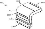
- FIGS. 11A-11Edepict a 5-degree-of-freedom chamfer cutting guide for creating multiple planar bone cuts in accordance with embodiments of the invention
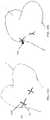
- FIGS. 12A-12Dillustrate the placement of pins to receive a 5-degree-of-freedom chamfer cutting guide in accordance with embodiments of the invention
- FIGS. 13A and 13Bdepicts a pin alignment guide for aligning a pin in a specific location on a bone in accordance with embodiments of the invention
- FIGS. 14A and 14Bdepicts a cutting guide with attachment holes spaced a distance apart in accordance with embodiments of the invention
- FIGS. 15A and 15Billustrates at least two perpendicular channels created on the bone to receive the pin alignment guide in accordance with embodiments of the invention
- FIGS. 16A and 16Bdepicts a referencing clamp alignment guide for creating pilot holes on the bone to align a N-in-1 cutting block in accordance with embodiments of the invention
- FIGS. 16C and 16Dillustrates the use of the referencing clamp alignment guide in accordance with embodiments of the invention
- FIG. 16Eillustrates a stepped diameter drill bit for use with the reference alignment guide in accordance with embodiments of the invention
- FIGS. 17A and 17Bdepict a plane clamp alignment guide for creating pilot holes on a distal cut surface to align a N-in-1 cutting block in accordance with embodiments of the invention
- FIG. 17Cillustrates the use of the plane alignment guide in accordance with embodiments of the invention.
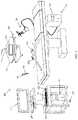
- FIGS. 18A and 18Bdepict a cross-section of a articulating pin-driver device, where FIG. 18A depicts the device having a pin in a retracted state, and FIG. 18B depicts the device having a pin in an extended state in accordance with embodiments of the invention;
- FIG. 18Cis an exploded view that illustrates the components of a working portion of the pin-driver device in accordance with embodiments of the invention.
- FIGS. 19A and 19Bdepicts and illustrate a bone stability member attached to the pin-driver device and the use thereof in accordance with embodiments of the invention
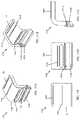
- FIGS. 20A and 20Bdepicts a partial enclosure enclosing the working portion in accordance with embodiments of the invention.
- FIGS. 21A and 21Bdepicts a full enclosure enclosing the working portion in accordance with embodiments of the invention.
- the present inventionhas utility as a system and method to aid a surgeon in efficiently and precisely aligning a cutting guide on a patient's bone.
- the system and methodis especially advantageous for total knee arthroplasty and revision knee arthroplasty, however, it should be appreciated that other medical applications may exploit the subject matter disclosed herein such as high tibial osteotomies, spinal reconstruction surgery, and other procedures requiring the precise placement of a cutting guide to aid a surgeon in creating bone cuts.
- Embodiments of the present inventionmay be implemented with a surgical system.
- surgical systems used in embodiments of the inventionillustratively include a 1-6 degree of freedom hand-held surgical system, a serial-chain manipulator system, a parallel robotic system, or a master-slave robotic system, as described in U.S. Pat. Nos. 5,086,401, 7,206,626, 8,876,830 and 8,961,536, U.S. Pat. App. No. 2013/0060278, and U.S. Prov. App. No. 62/054,009.
- the surgical systemis a serial-chain manipulator system as described in U.S. Pat. No.
- the manipulator systemmay provide autonomous, semi-autonomous, or haptic control and any combinations thereof.
- a tool attached to the manipulator systemmay be manually maneuvered by a user while the system provides at least one of power, active or haptic control to the tool.
- FIG. 1illustrates a 2-degree-of-freedom (2-DOF) surgical system 100 .
- the 2-DOF surgical system 100is generally described in PCT App. Num. US2015/051713, assigned to the assignee of the present application and incorporated by reference herein in its entirety.
- the 2-DOF surgical system 100includes a computing system 102 , an articulating surgical device 104 , and a tracking system 106 .
- the surgical system 100is able to guide and assist a user in accurately placing pins coincident with a virtual pin plane that is defined relative to a subject's bone.
- the virtual planeis defined in a surgical plan such that a cut guide when assembled to the inserted pins align one or more guide slots with the bone cuts required to receive a prosthetic implant in a planned position and orientation.
- FIGS. 2A and 2Billustrate the articulating surgical device 104 of the 2-DOF surgical system 100 in more detail.
- the surgical device 104includes a hand-held portion 202 and a working portion 204 .
- the hand-held portion 202includes an outer casing 203 of ergonomic design to be held and manipulated by a user.
- the working portion 204includes a tool 206 having a tool axis 207 .
- the tool 206is readily attached to and driven by a motor 205 .
- the hand-held portion 202 and working portion 204are connected by a front linear rail 208 a and a back linear rail 208 b that are actuated by components in the hand-held portion 202 to control the pitch and translation of the working portion 204 relative to the hand-held portion 202 .
- a tracking array 212having three or more fiducial markers, is rigidly attached to the working portion 142 to permit a tracking system 106 to track the POSE of the working portion 204 .
- the fiducial markersmay be active markers such as light emitting diodes (LEDs), or passive markers such as retroreflective spheres.
- An input/output portin some inventive embodiments provides power and/or control signals to the device 104 ; or the device may receive power from batteries and control signals via a wireless connection alleviating the need for electrical wiring to be connected to the device 104 . In a particular embodiment, the device may receive wireless control signals via visible light communication as described in Int'l Pat. App. WO 2016/081931 assigned to the assignee of the present application and incorporated by reference herein in its entirety.
- the device 104may further include one or more user input mechanisms such as a trigger 214 or a button.
- a front actuator 210 athat powers a front ball screw 216 a and a back actuator 210 b that powers a back ball screw 216 b .
- the actuators ( 210 a , 210 b )may be servo-motors that bi-directionally rotate the ball screws ( 216 a , 216 b ).
- a first end of the linear rails ( 208 a , 208 b )are attached to the working portion 204 via hinges ( 220 a , 220 b ), where the hinges ( 220 a , 220 b ) allow the working portion 204 to pivot relative to the linear rails ( 208 a , 208 b ).
- Ball nuts ( 218 a , 218 b )are attached at a second end of the linear rails ( 208 a , 208 b ).
- the ball nuts ( 218 a , 218 b )are in mechanical communication with the ball screws ( 216 a , 216 b ).
- the actuators ( 210 a , 210 b )power the ball screws ( 216 a , 216 b ) which cause the ball nuts ( 218 a , 218 b ) to translate along the axis of the ball screws ( 216 a , 216 b ).
- the translation ‘d’ and pitch ‘ ⁇ ’ of the working portion 204may be adjusted depending on the position of each ball nut ( 218 a , 218 b ) on their corresponding ball screw ( 216 a , 216 b ).
- a linear guide 222may further constrain and guide the motion of the linear rails ( 208 a , 208 b ) in the translational direction ‘d’.
- the computing system 102generally includes hardware and software for executing a surgical procedure.
- the computing system 102provides actuation commands to the actuators ( 210 a , 210 b ) to control the position and orientation (POSE) of the tool 206 .
- the computing system 102can thus maintain the tool axis 207 with a virtual plane defined in a surgical plan independent of the POSE of the hand-held portion 202 .
- the computing system 102in some inventive embodiments includes: a device computer 108 including a processor; a planning computer 110 including a processor; a tracking computer 111 including a processor, and peripheral devices.
- processorsoperate in the computing system 102 to perform computations associated with the inventive system and method. It is appreciated that processor functions are shared between computers, a remote server, a cloud computing facility, or combinations thereof.
- the device computer 108may include one or more processors, controllers, and any additional data storage medium such as RAM, ROM or other non-volatile or volatile memory to perform functions related to the operation of the surgical device 104 .
- the device computer 108may include software, data, and utilities to control the surgical device 104 such as the POSE of the working portion 204 , receive and process tracking data, control the speed of the motor 205 , execute registration algorithms, execute calibration routines, provide workflow instructions to the user throughout a surgical procedure, as well as any other suitable software, data or utilities required to successfully perform the procedure in accordance with embodiments of the invention.
- the device computer 108 , the planning computer 110 , and the tracking computer 111may be separate entities as shown, or it is contemplated that their operations may be executed on just one or two computers depending on the configuration of the surgical system 100 .
- the tracking computer 111may have operational data to control the device 104 without the need for a device computer 108 .
- the device computer 108may include operational data to plan to the surgical procedure with the need for the planning computer 110 .
- the planning computer 110is preferably dedicated to planning the procedure either pre-operatively or intra-operatively.
- the planning computer 110may contain hardware (e.g. processors, controllers, and memory), software, data, and utilities capable of receiving and reading medical imaging data, segmenting imaging data, constructing and manipulating three-dimensional (3D) virtual models, storing and providing computer-aided design (CAD) files, planning the POSE of the implants relative to the bone, generating the surgical plan data for use with the system 100 , and providing other various functions to aid a user in planning the surgical procedure.
- the planning computeralso contains software dedicated to defining virtual planes with regards to embodiments of the invention as further described below.
- the final surgical plan datamay include an image data set of the bone, bone registration data, subject identification information, the POSE of the implants relative to the bone, the POSE of one or more virtual planes defined relative to the bone, and any tissue modification instructions.
- the device computer 108 and the planning computer 110may be directly connected in the operating room, or may exist as separate entities.
- the final surgical planis readily transferred to the device computer 108 and/or tracking computer 111 through a wired or wireless connection in the operating room (OR); or transferred via a non-transient data storage medium (e.g. a compact disc (CD), a portable universal serial bus (USB drive)) if the planning computer 110 is located outside the OR.
- the computing system 102may act as a single entity, with multiple processors, capable of performing the functions of the device computer 108 , the tracking computer 111 , and the planning computer 110 .
- the computing system 102may accurately maintain the tool axis 207 in 3-D space based on POSE data from the tracking system 106 as shown in FIG. 1 .
- the tracking system 106generally includes a detection device to determine the POSE of an object relative to the position of the detection device.
- the tracking system 106is an optical tracking system as described in U.S. Pat. No. 6,061,644, having two or more optical receivers 116 to detect the position of fiducial markers arranged on rigid bodies.
- the fiducial markersinclude: an active transmitter, such as an LED or electromagnetic radiation emitter; a passive reflector, such as a plastic sphere with a retroreflective film; or a distinct pattern or sequence of shapes, lines or other characters.
- a set of fiducial markers arranged on a rigid bodyis referred to herein as a fiducial marker array ( 120 a , 120 b , 120 c , 212 ), where each fiducial marker array ( 120 a , 120 b , 120 c , 212 ) has a unique geometry/arrangement of fiducial markers, or a unique transmitting wavelength/frequency if the markers are active LEDS, such that the tracking system 106 can distinguish between each of the tracked objects.
- the fiducial marker arrays ( 120 a , 120 b , 120 c , 212 )include three or more active emitters or passive reflectors uniquely arranged in a known geometry on each rigid body.
- the tracking system 106may be built into a surgical light 118 , located on a boom, stand, or built into the walls or ceilings of the operating room.
- the tracking system computer 111includes tracking hardware, software, data, and utilities to determine the POSE of objects (e.g. bones such as the femur F and tibia T, the surgical device 104 ) in a local or global coordinate frame.
- the POSE of the objectsis referred to herein as POSE data, where this POSE data is readily communicated to the device computer 108 through a wired or wireless connection.
- the device computer 108may determine the POSE data using the position of the fiducial markers detected directly from the optical receivers 116 .
- the POSE datais determined using the position of the fiducial markers detected from the optical receivers 116 and operations/processes such as image processing, image filtering, triangulation algorithms, geometric relationship processing, registration algorithms, calibration algorithms, and coordinate transformation processing.
- POSE data from the tracking system 106is used by the computing system 102 to perform various functions.
- the POSE of a digitizer probe 130 with an attached probe fiducial marker array 120 cmay be calibrated such that tip of the probe is continuously known as described in U.S. Pat. No. 7,043,961.
- the POSE of the tip or axis of the tool 206may be known with respect to the device fiducial marker array 212 using a calibration method as described in Int'l Pat. App. No. WO 2016/141378.
- Registration algorithmsare readily executed using the POSE data to determine the POSE and/or coordinate transforms between a bone, a surgical plan, and a surgical system. For example, in registration methods as described in U.S. Pat. Nos.
- points on a patient's bonemay be collected using a tracked digitizer probe to transform the coordinates of a surgical plan, coordinates of the bone, and the coordinates of a surgical device,
- the bonemay also be registered using image registration as described in U.S. Pat. No. 5,951,475.
- the coordinate transformationsmay be continuously updated using the POSE data from a tracking system tracking the POSE of the bone post-registration and the surgical device.
- an optical tracking system 106 with optical receivers 116is used to collect POSE data of the femur and tibia during total knee arthroplasty.
- the distal femur F and proximal tibia Tare exposed as in a typical TKA procedure.
- Tracking arrays 120 a and 120 bare attached thereto and the femur F and tibia T are subsequently digitized and registered to a surgical plan.
- the POSE of the femur F and tibia Tare tracked in real-time by the tracking system 106 so the coordinate transformation between the surgical plan and the surgical device are updated as the bones and surgical device move in the operating space.
- a relationship between the POSE of the tool 206 and the POSE of any coordinates defined in the surgical planmay be determined by the computing system 102 .
- the computing system 102can supply actuation commands to the actuators ( 210 a , 210 b ) in real-time to accurately maintain the tool axis 207 to the defined coordinates.
- user input mechanismssuch as the trigger 214 or foot pedal 128 , may be used by the user to indicate to the computing system 102 that the tool axis 207 needs to be maintained to other coordinates defined in a surgical plan.
- the tool axis 207may be maintained in a first defined plane, and the user may step on the foot pedal 128 to relay to the computing system 102 that the tool axis 207 needs to be maintained in a second defined plane.
- TKATotal Knee Arthroplasty
- the surgical planis created, either pre-operatively or intra-operatively, by a user using planning software.
- the planning softwaremay be used to a generate three-dimensional (3-D) models of the patient's bony anatomy from a computed tomography (CT), magnetic resonance imaging (MRI), x-ray, ultrasound image data set, or from a set of points collected on the bone intra-operatively.
- CTcomputed tomography
- MRImagnetic resonance imaging
- x-rayultrasound image data set
- a set of 3-D computer aided design (CAD) models of the manufacturer's prosthesisare pre-loaded in the software that allows the user to place the components of a desired prosthesis to the 3-D model of the boney anatomy to designate the best fit, position and orientation of the implant to the bone.
- CADcomputer aided design
- the planned cut planesgenerally include the anterior cut plane 306 , anterior chamfer cut plane 308 , the distal cut plane 310 , the posterior chamfer cut plane 312 , the posterior cut plane 314 and the tibial cut plane (not shown).
- the surgical plancontains the 3-D model of the patient's operative bone combined with the location of one or more virtual planes 316 .
- the location of the virtual plane(s) 316is defined by the planning software using the position and orientation (POSE) of one or more planned cut planes and one or more dimensions of a cutting guide or alignment guide.
- the location of the virtual plane(s) 316is defined to aid in the placement of a cutting guide such that one or more guide slots of the cutting guide are in the correct POSE to accurately guide a saw in creating the bone cuts.
- Embodiments of the various inventive cutting guides, alignment guides, defining of the virtual planes, and use of the bone pinsare further described in detail below.
- embodiments of the inventive cutting guides and alignment guides disclosed hereinmay be made of a rigid or semi-rigid material, such as stainless steel, aluminum, titanium, polyetheretherketone (PEEK), polyphenylsulfone, acrylonitrile butadiene styrene (ABS), and the like.
- Embodiments of the cutting guides and alignment guidesmay be manufactured using appropriate machining tools known in the art.
- a particular inventive embodiment of a cutting guide to accurately create the planned distal cut 310is the universal distal cutting guide 400 as depicted in FIG. 4A and FIG. 4B .
- the distal cutting guide 400includes a guide portion 402 and an attachment portion 404 .
- the guide portion 402includes a guide slot 406 and a bottom surface 410 .
- the guide slot 406is for guiding a surgical saw in creating the distal cut 310 on the femur.
- the bottom surface 410abuts against one or more bone pins 412 that are placed on the bone.
- the attachment portion 404 and the guide portion 402clamp to the bone pins 412 using fasteners 408 as shown in FIG. 4B and FIG. 4D .
- a surgical systemis used to place the longitudinal axis of the bone pins 412 on a virtual pin plane 414 .
- the 2-DOF surgical system 100is used, wherein the tool 206 of the surgical device 104 is a drill bit rotated by the drill 205 .
- the computing systemsupplies actuation commands to the actuators to align the tool axis 207 with the pin plane 414 .
- the virtual pin plane 414is defined in the surgical plan by the planning software using the POSE of the planned distal cut plane 310 , and the distance between the guide slot 406 and the bottom surface 410 of the guide portion 402 .
- the planning softwaremay also use the known width of the bone pins 412 .
- the pin plane 414can be defined by proximally translating the planned distal cut plane 310 by the distance between the guide slot 406 and the bottom surface 410 of the distal cutting guide 400 .
- the softwaremay further proximally translate the planned distal cut plane 310 by an additional half width of the pins 412 . Therefore, when the cutting guide 400 is clamped to the bone pins 412 , the guide slot 406 is aligned with the planned distal cut plane 310 .
- the user or the computing system 102may activate the drill when properly aligned with the pin plane 414 to drill pilot holes for the pins 412 .
- the pins 412are then drilled into the pilot holes using a standard drill.
- the tool 206is the pin 412 , wherein the pin 412 is attached to the drill 205 of the surgical device 104 and drilled directly into the bone on the pin plane 414 .
- At least two bone pins 412may be drilled on the pin plane 414 to constrain the distal cutting guide 400 in the proper position and orientation when clamped to the pins 412 however three or more bone pins 412 can be used for further stability.
- the surgical device 104is actuating in real-time, therefore the user is actively guided to the POSE of the pin plane 412 .
- the correct position and orientation of the bone pins 412is accurately maintained regardless of the surgeon's placement of the hand-held portion 204 of the 2-DOF surgical system 100 .
- One main advantage of the cutting guide 400is its universality because the cutting guide 400 may be used for any type of implant and any type of patient. This is particularly advantageous, because the universal distal cutting guide 400 can be sterilized and re-used for multiple surgeries, greatly reducing the cost of TKA, which otherwise requires either patient specific cutting guides or implant specific cutting guides for each surgery.
- the advantageous part of using pin planesis the user can place the longitudinal axes of the pins in any arbitrary orientation and position on the plane 414 and still attach the cutting guide 400 such that the guide slot 406 is accurately aligned with the planned distal cut plane 310 . This greatly reduces the operational time of the procedure.
- the usercan avoid any particular landmarks coincident with the virtual plane if so desired.
- the usercan saw the distal cut 416 on the femur F by guiding a surgical saw through the guide slot 406 . Subsequently, the bone pins 412 and cutting guide 400 are removed from the bone to create the remaining bone cuts.
- FIGS. 5A-5Da prior art 4-in-1 cutting block 500 is used to create the remaining bone cuts.
- FIG. 5Ais a perspective view of the 4-in-1 cutting block
- FIG. 5Bis a side elevation view thereof
- FIG. 5Cis a top plan view thereof
- FIG. 5Dis a bottom plan view thereof.
- the 4-in-1 cutting block 500may be made of materials similar to that of the distal cutting guide 400 .
- the 4-in-1 cutting block 500is manufactured to include a body 502 , a posterior guide slot 504 , a posterior chamfer guide slot 506 , an anterior chamfer guide slot 508 , and an anterior guide slot 510 .
- the cutting block 500also includes two pegs 512 to fit into pilot holes to be drilled on the distal cut plane 416 , and two pin securing guides 514 to receive pins 412 ′ to secure the cutting block 500 to the femur F.
- a 4-in-1 cutting block 500is described herein, it should be appreciated that any N-in-1 cutting block for creating additional cut-planes on the bone may be aligned and assembled on the bone using the embodiments described herein.
- An N-in-1 cutting blockcan account for femoral prostheses having greater than 5 planar contact surfaces (for reference and clarity, the femoral prosthesis 304 shown in FIG. 3 has 5 planar contact surfaces including the posterior contact surface 318 that mates with the posterior cut plane 314 ).
- the 4-in-1 cutting block 500may be aligned on the bone using an alignment guide.
- a particular embodiment of the alignment guideis a planar alignment guide 600 as shown in FIG. 6A and FIG. 6B .
- FIG. 6Ais a perspective view of the planar alignment guide 600
- FIG. 6Bis a top plan view of thereof.
- the planar alignment guide 600includes a body 602 , and two holes 604 integrated with the body 602 .
- the body 602includes a bottom portion 606 adapted to fit in a channel 800 (shown in FIG. 8A ) to be milled on the distal cut plane 416 .
- the distance between the centers of the holes 604correspond to the distance between the centers of the pegs 512 of the 4-in-1 block 500 .
- FIG. 7Ais a perspective view of the alignment guide 700
- FIG. 7Bis a bottom plan view thereof.
- the alignment guide 700includes a body 702 , at least one ridge 704 at the edge and extending from the body 702 , and two holes 604 ′ bored through the body 702 , where the two holes 604 ′ are located a known distance from the ridge 604 .
- the distance between the centers of the two holes 604 ′correspond to the distance between the pegs 512 of the 4-in-1 cutting block 500 .
- the at least one ridge 704is adapted to fit in a channel 800 (shown in FIG. 8A ) to be milled on the distal cut plane 416 .
- the location of the pegs 512 on the distal cut plane 310is determined based on the planned size and location of the prosthesis such that the guide slots of the 4-in-1 cutting block 500 align with the remaining bone cut planes.
- the planning softwarecan define a virtual channel plane in the surgical plan, in which a channel 800 will be milled to receive the alignment guide ( 600 , 700 ).
- the channel planeis defined by a plane that is perpendicular to the distal cut plane and aligned with the medial-lateral direction of the prosthesis.
- the channel planeis defined based on the POSE of the planned anterior cut plane 306 or posterior cut plane 314 , and the location of the pegs required to align the guide slots for the remaining bone cuts.
- the planning softwarecan define a virtual channel plane by anteriorly translating the planned posterior cut plane 314 to the location of the center of the pegs 512 of the 4-in-1 cutting block 500 .
- the virtual channel planeis defined by anteriorly translating the planned posterior cut plane 314 to the location of the pegs 512 , and then posteriorly/anteriorly translating the planned plane by the known distance between the center of the holes 604 ′ and the ridge 704 .
- the virtual channel plane defined in the surgical planis used to create a channel 800 on the distal cut plane 310 of the femur F with a surgical system as shown in FIGS. 8A-8D .
- the 2-DOF surgical system 100is used wherein the tool 206 of the surgical device 104 is actuated such that the tool axis 207 remains substantially coincident with the channel plane.
- the tool 206is a bone cutting tool such as an end mill, burr or a rotary cutter.
- the tool 206may further include a sleeve to prevent the tool 206 from cutting the channel 800 too deep.
- the alignment guideis placed in the channel, whereby the holes 604 ′ are aligned with the position for the pegs 512 of the 4-in-1 cutting block 500 .
- the planar alignment guide 600the bottom portion 606 of the body 602 fits directly in the channel.
- the offset alignment guide 700the ridge 704 fits directly into the channel 800 as shown in FIGS. 8C and 8D .
- a standard drillis then used to drill pilot holes for the pegs 512 by drilling through the holes 604 ′ of the alignment guide.
- the alignment guideis removed from the femur F.
- the 4-in-1 block 500is attached to the femur F via the pegs 512 .
- the remaining four bone cuts on the femur Fare created using a surgical saw guided by the guide slots of the 4-in-1 cutting block 500 .
- the 4-in-1 block 500is then removed, and the femoral prosthesis can be fixed to the femur F in a conventional manner.
- a particular advantage in using the offset alignment guide 700 as opposed to the planar alignment guide 600is the created channel 800 to receive the ridge 704 can be removed with one of the four planar cuts, depending on the distance between the ridge 704 and the holes 604 ′.
- the use of the channel plane with an alignment guide ( 600 , 700 )is advantageous because position of the cutting block 500 in the medial-lateral direction does not need to be precise on the distal cut 416 as long as the guide slots of the 4-in-1 cutting block 500 span enough of the bone to create the remaining bone cuts. Additionally, by using a surgical system, the channel can be quickly and accurately created.
- a distal cutting and alignment guide 900is illustrated in FIG. 9A and FIG. 9B .
- a front perspective view of the distal cutting guide 900is shown in FIG. 9A
- a rear perspective view thereofis shown in FIG. 9B .
- the distal cutting and alignment guide 900includes a guide portion 902 and an attachment portion 904 .
- the guide portion 902may be in the shape of an inverted “L”, with a distal guide slot 906 and a pair of holes 908 bored through. The distance between the centers of the two holes 908 correspond to the distance between the pegs 512 of the 4-in-1 block 500 .
- the guide portion 902also includes an abutment face 912 adapted to abut against alignment pins 914 .
- the attachment portion 904attaches to the guide portion 902 with fasteners 910 to clamp bone pins 912 to the distal cutting and alignment guide 900 .
- the planning softwaredefines two virtual planes to accurately place the cutting and alignment guide 900 to the femur F.
- a first pin planeis defined such that the guide slot 906 aligns with the planned distal cut plane 310 when the cutting guide 900 is assembled to the bone pins 912 .
- a second pin planeis defined such that when the face 912 abuts against the alignment pins 914 second pin plane, the holes 908 align with the POSE for the pegs 512 of the 4-in-1 cutting block 500 .
- the first pin planeis defined for the bone pins 912 and the second pin plane is defined for the alignment pins 914 .
- the second pin planeis defined in the planning software as follows: 1) a plane is defined perpendicular to the planned distal cut plane 310 and parallel with the planned position for the pegs 512 , and 2) that plane is then posteriorly translated by the distance between the centers of the holes 908 and the face 912 of the distal cutting and alignment guide 900 . Therefore, when the face 912 abuts against the alignment pins 914 , the holes 908 are accurately aligned in the anterior/posterior direction and internal-external rotation.
- the bone pins 912 and alignment pins 914are accurately placed on the first and second pin planes using a surgical system as described above.
- the cutting guide 900is then assembled to the femur F, wherein the face 912 abuts against the alignment pins 914 as shown in FIG. 9D .
- two pilot holesare drilled through the holes 908 .
- the alignment pins 914are removed and the distal cut 416 is made by guiding a surgical saw through the guide slot 906 .
- the cutting guide 900is removed from the femur F, and the 4-in-1 guide block can be directly assembled in the pilot holes to aid in creating the remaining cuts.
- FIG. 10Ais a perspective view of the slot alignment guide 1000
- FIG. 6Bis a top plan view thereof.
- the slot alignment guide 1000includes two holes 1002 , and a pin receiving slot 1004 .
- the slot alignment guide 1000may further include a lip 1006 .
- the distance between the centers of the two holes 1002correspond to the distance between the pegs 512 of the 4-in-1 block 500 .
- the pin receiving slot 1004is of sufficient width to be received on the bone pins 1008 .
- the distance between the center of the slot 1004 and the holes 1002are known to define a virtual pin plane for the bone pins 1008 .
- the slot alignment guide 1000may be used if the cancellous bone on the distal surface 416 of the femur F is particularly soft, weak, or more flexible. In these cases, the planar alignment guide 600 or the offset alignment guide 700 in the channel 800 may become misaligned due to the flexible nature of this cancellous bone. Therefore, bone pins 1008 may be inserted on the channel plane as defined above. The bone pins 1008 are aligned and inserted on the channel plane using the methods previously described as shown in FIG. 10C . A ring 1010 such as a washer or spacer may be placed on the bone pins 1008 to further protect the distal surface 416 of the femur F. The pin receiving slot 1004 of the slot alignment guide 1000 is placed on the bone pins 1000 .
- the lip 1006may interact with the ring 1010 such that the alignment guide 1000 lies flat on the distal surface 416 of the femur F.
- a usermay then drill pilot holes through the holes 1002 using a standard drill.
- the alignment guide 1000 and the bone pins 1008are removed from the femur F and the pegs 512 of the 4-in-1 guide block 500 is assembled to the pilot holes to aid in creating the remaining bone cuts.
- the 4-in-1 blockmay have other features, other than the pegs 512 , to interact and attach with the distal cut surface 416 of the femur F.
- the pegs 512may instead be a body extruding from the bottom surface of the 4-in-1 block 500 and adapted to fit in a corresponding shape created on the distal cut surface 416 .
- the extruding bodymay have a variety of shapes including an extruded rectangle, triangle, the shapes manufactured for a keel of a tibial base plate implant, and any other extruding body/bodies.
- the alignment guides described hereinmay have the same corresponding shape, instead of the holes ( 604 , 604 ′, and 908 ), to guide a user in creating that shape on the distal cut surface 416 so the 4-in-1 block can be accurately placed thereon.
- a clamp alignment guide( 1600 , 1700 ) is used to aid in the alignment of an N-in-1 cutting block on the femur.
- the clamp alignment guides ( 1600 , 1700 )are configured to clamp onto their own set of pins in a POSE that permits a user to accurately create the pilot holes for the cutting block pegs 512 .
- a referencing clamp alignment guide 1600 and the use thereofis shown.
- the referencing clamp alignment guide 1600includes a guide portion 1602 and a clamping portion 1604 .
- the guide portion 1602has a pair of referencing feet 1606 that reference a top surface 409 of the universal distal cutting guide 400 ′, and two or more holes 1608 spaced a distance apart corresponding to the distance between the pegs 512 of a cutting block.
- the virtual pin plane for the clamp alignment guides( 1600 , 1700 ) is defined by: 1) defining a plane perpendicular to the planned distal cut plane 310 and parallel with the planned position for the pegs 512 ; 2) posteriorly translating that plane by the known distance between the centers of the holes 1608 and a bottom surface 1609 of the alignment portion 1602 ; and 3) further posteriorly translating that plane by an additional half-width of the pins 1610 .
- a universal cut guide 400 ′is first assembled on the femur F as described above.
- the pins 1610are positioned on the virtual pin plane using a surgical system, such as the 2-DOF surgical system 100 .
- the clamp guide 1600is assembled on the pins 1610 with the feet 1606 referencing the top surface 409 of the universal cut guide 400 ′.
- the userthen drills the pilot holes for the cutting block pegs 512 using the holes 1608 as a guide.
- the clamp alignment guide 1600 and pins 1610are removed from the bone and the user creates the distal cut via the guide slot 406 .
- the distal cut guide 400 ′ and distal pins 412are removed from the bone, the cutting block pegs 512 are inserted in the pilot holes, and the remaining cut planes are created on the femur.
- FIG. 16Edepicts the distal cut guide 400 ′ and reference clamp guide 1600 assembled on the bone, and a drill 1618 driving a stepped diameter drill bit 1617 through the guide holes 1608 .
- a drill bit 1617 having a stepped diametercan simultaneously clear the length of the pins 1610 and also set the engagement in the bone beyond the distal cut plane 1612 so the user does not have to determine how deep to drill.
- the drill bit 1617has a distal portion 1619 having a diameter less than a proximal portion 1620 .
- the distal portion 1619has a diameter that fits through the guide holes 1608 and large enough to create a hole for receiving the cutting block pegs 512 .
- the distal portion 1619has a length capable of traversing the bone distal of the distal cut plane 1619 and extend beyond the distal cut plane 1612 enough to create a pilot hole deep enough to fully receive the pegs 512 .
- the proximal portion 1620has a diameter larger than the diameter of the guide holes 1608 and a length that ensures the bulky drill 1618 does not interfere with pins 1610 .
- the drill 1618is tracked by a tracking system and a monitor provides visual feedback to the user.
- a monitorprovides visual feedback to the user.
- the monitordisplays this information and/or provides depth information.
- a plane clamp alignment guide 1700is used to aid in the creation of the pilot holes to receive the cutting block pegs 512 .
- the plane alignment guide 1700is placed directly on the distal cut plane 416 and includes a guide portion 1702 and a clamping portion 1704 .
- the guide portion 1700includes two or more holes 1706 similar to the reference alignment guide 1600 .
- the guide 1700may further include a projection 1708 to increase the contact surface area between the guide 1700 and the distal cut surface 416 to increase the stability of the guide on the distal surface 416 .
- the bottom surface 1712 of the plane alignment guide 1700is flat to mate with the planar distal cut surface 416 .
- Fasteners 1710 or a clamping mechanismallows the plane guide 1700 to assemble to the pins 1714 inserted on the bone.
- the procedure for using the plane alignment guide 1700is as follows.
- the userfirst creates the distal cut using a universal distal cutting guide 400 .
- the userthen inserts pins 1714 on a virtual pin plane, where the virtual pin plane is defined as described above for the clamp alignment guides ( 1600 , 1700 ).
- the pins 1714are inserted directly on the distal cut surface 416 .
- the plane alignment guide 1700is then clamped to the pins 1714 where the bottom surface 1712 of the guide 1700 lies flush with the cut surface 416 .
- the userdrills the pilot holes for the pegs 512 using the holes 1706 as a guide.
- the pins 1714 and the plane alignment guide 1700are removed, the pegs 512 of an N-in-1 cutting block are placed in the pilot holes, and the remaining cut planes are created.
- the clearance issue described above for the reference alignment guide 1600can be readily solved in a similar manner for the plane alignment guide 1700 .
- FIGS. 11A-11Ea 5-DOF chamfer cutting guide 1100 is shown in FIGS. 11A-11E .
- FIG. 11Ais a perspective view of the top of the chamfer cutting guide 1100
- FIG. 11Bis a perspective view of the bottom thereof
- FIG. 11Cis a top plan view
- FIG. 11Dis a front elevation view
- FIG. 11 Eis a side elevation view.
- the chamfer cutting guide 1100includes a guide body 1102 in the shape of an inverted “L”.
- the guide body 1102includes a first attachment slot 1104 a , a second attachment slot 1104 b , a distal guide slot 1106 , an anterior guide slot 1108 , and a chamfer guide slot 1110 .
- One side of the attachment slots 1104is open, so the chamfer cutting guide 1100 can slide onto the bone pins.
- the attachment slot openingis best visualized in FIG. 11D on the right side of the attachment slots 1104 .
- the planning softwaredefines the location of 5-DOF chamfer cutting guide 1100 in the location necessary to place the guide slots in the correct position and orientation to accurately execute the planned cut planes.
- the surgical planalso includes two pin planes ( 1202 a , 1202 b , as shown in FIGS. 12A-12B ), on which bone pins ( 1204 a , 1204 b ) are placed that are defined relative to the cut planes; the two planes have an intersection axis that is parallel to all of the cut planes.
- the pin planes ( 1202 a , 1202 b )may be defined using the known dimensions of the chamfer cutting guide 1100 , and the POSE of the planned cut planes.
- the planning softwareknows the position and orientation of the attachment slots 1104 with respect to the guide slots. Using these dimensions the planning software may define a first pin plane 1204 a and a second pin plane 1204 b . By defining two pin planes with four or more pins, 5 degrees of freedom are constrained, which is sufficient to perform a TKA procedure using a surgical saw if the unconstrained degree of freedom is in the medial-lateral direction, which is parallel to all of the cut planes.
- a surgical systemsuch as the one described above, is then used to place the bone pins ( 1204 a . 1204 b ) substantially coincident on the pin planes ( 1202 a , 1202 b ).
- the pins 1204can be inserted at an arbitrary position and orientation on that plane.
- the attachment slots 1104 of the chamfer cutting guide 1100slide over the bone pins ( 1204 a . 1204 b ) as shown in FIG. 12C .
- the userthen creates the distal cut plane, anterior cut plane, posterior cut plane, and the chamfer cut planes by guiding a surgical saw through the respective guide slots.
- the chamfer guide 1100 and the bone pins 1204are then removed.
- a second cut guide(not shown), which fits against the distal and posterior cut surfaces can guide the anterior cut using similar embodiments of the cutting guides, pin planes, and bone pins as described herein.
- a pin alignment guide 1300is shown in FIG. 13A and FIG. 13B .
- the pin alignment guide 1300includes a tubular body 1302 and fins 1304 extruding outwardly from the tubular body 1302 .
- the pin alignment guide 1300aids a user in aligning bone pins for use with a cutting guide that requires the bone pins to be placed a specific distance apart.
- the cutting guide 1400 shown in FIGS. 14A and 14Bincludes a guide slot 1402 , and two holes 1404 that receive bone pins placed a specific distance apart.
- a first channel planeto create a first channel 1502 on the bone, is defined as described above using the planned distal cut plane 310 and the distance between the guide slot 1402 and the center of the holes 1404 .
- a second channel planeto create a second channel 1504 on the bone, is defined perpendicular to the first channel plane.
- a third channel planeis defined perpendicular to the first channel plane and medially/laterally translated by the distance between the centers of the holes 1404 of the cutting guide 1400 .
- the channels ( 1502 , 1504 )are precisely milled on the bone using a surgical system as described above.
- the intersection of the first channel 1502 and the second channel 1504receives the pin alignment guide 1300 as shown in FIG. 15B , wherein the fins 1304 fit directly into the channels.
- a usercan then drill a pilot hole, or a bone pin directly through the tubular body 1302 of the pin alignment guide 1300 .
- the procedureis repeated to place any additional bone pins on the bone.
- the holes 1404 of the cutting guide 1400are placed on the bone pins, and the bone cut is created as planned.
- this techniquecan similarly be used for other cutting guides.
- the pin alignment guide techniquecan be used to create pilot holes on the distal cut 416 of the femur F for the pegs 512 of a 4-in-1 block 500 .
- the tibial cut planemay be created using similar embodiments as described above and should be apparent to one skilled in the art after reading the subject matter herein.
- the tibial cut guidemay be aligned in varus-valgus rotation, internal-external rotation, flexion-extension rotation, and proximal-distal position.
- the anterior-posterior positionis not important.
- the tibial cut guideis positioned using two or more pins positioned on two planes that have an intersection axis that is aligned with the planned anterior-posterior direction. For example, two planes oriented ⁇ 45° in varus-valgus, such that when the guide is placed on the pins, all degrees of freedom except the anterior-posterior are constrained.
- femoral and tibia saw boneswere tested using the 2-DOF surgical system 100 , the universal distal cutting guide 400 , the offset alignment guide 700 and the 4-in-1 block 500 . Artificial ligaments were attached between the saw bones to mimic the kinematics of the knee. The purpose of the testing was to assess the overall time required to create the planar cuts on the femoral saw bone, referred to hereafter as femur. The timing began prior to fixing the femoral tracking array 120 b and ended once the last cut plane on the femur was completed.
- the femoral tracking array 120 bwas fixed to the lateral side of the femur.
- a tracked digitizer probewas used to collect various points on the distal femoral surface. The collected points were used to register the POSE of the femur to a surgical plan.
- the 2-DOF surgical device 104was used to drill two holes in the virtual pin plane 414 , the virtual pin plane 414 being defined in the planning software prior to testing.
- a standard drillwas then used to insert pins 412 in the drilled holes.
- the universal distal cutting guide 400was clamped to the pins 412 and the distal cut 416 was created using a surgical saw guided through the slot 406 of the distal cutting guide 400 . The distal cutting guide 400 and pins 412 were then removed from the femur.
- the 2-DOF surgical device 104was then used to mill a channel 800 on the distal cut surface 416 along the virtual channel plane, the virtual channel plane being defined in the planning software prior to testing.
- the ridge 704 of the offset alignment guide 700was placed in the channel 800 and a standard drill was used to drill two holes on the distal surface 416 guided by the two holes 604 ′ of the offset alignment guide 700 .
- the offset alignment guide 700was removed from the channel 800 and the pegs 512 of the 4-in-1 block 500 were placed in the two drilled holes.
- the remaining four planar cutswere created using a surgical saw guided by the guide slots ( 504 , 506 , 508 , and 510 ) of the 4-in-1 block 500 .
- the recorded time from femoral tracking array 120 b fixation to the creation of the final cut planewas approximately 18 minutes.
- the articulating device 204 of the 2-DOF surgical system 100 described abovecan accurately align a tool/pin to be coincident with one or more virtual planes. However, the surgeon still has to manually advance the device 204 towards the bone to insert the pin or to create a pilot hole for the pin, which may be uncomfortable for the surgeon. In addition, it is possible that extreme or sudden movements by the surgeon or bone while operating the device may introduce small errors in the pin alignment. A contributing factor to the extreme or sudden movements may be a lacking of real-time information, during use, as to the articulating travel range, or workspace, in which the device operates 204 within.
- the 2-DOF surgical device 104may be modified to include a third pin-driving degree-of-freedom, which will be referred to hereinafter as an articulating pin-driver device 104 ′.
- an articulating pin-driver device 104 ′With reference to FIGS. 18A-18C in which like reference numerals have the meaning ascribed to that numeral with respect to the aforementioned figures, a particular embodiment of the articulating pin driver device 104 ′ is shown.
- the working portion 204 ′ of the articulating pin driver device 104 ′further includes components configured to drive a pin 206 ′ into a bone. Specifically, with reference to FIG.
- the working portion 204 ′includes the motor 205 , a motor coupler 1808 , a pin-driving ball screw 1804 , a pin holder 1806 , and the pin 206 ′.
- a specially adapted carriage 1810is configured to support and carry the working portion 204 ′ and may include mechanisms for actuating the pin.
- the carriage 1810includes a pin-driving ball nut 1812 and connection members 1814 such as holes, bearings, or axle supports to receive a rod, a dowel, or an axel to act as the hinges ( 220 a , 220 b ) that are connected with the first end of the linear rails ( 208 a , 208 b ).
- the motor coupler 1808couples the motor 205 with the pin-driving ball screw 1804 .
- the pin-driving ball screw 1804is in mechanical communication with the pin-driving ball nut 1812 .
- the pin holder 1806connects the pin-driving ball screw 1804 with the pin 206 ′.
- the pin 206 ′is removably attached with the pin holder 1806 to allow the pin 206 ′ to remain in the bone when inserted therein.
- the motor 205may bi-rotationally drive the pin-driving ball screw 1804 and the pin 206 ′ to advance and drive the pin 206 ′ into a bone.
- the componentsmay further include a motor carriage (not shown) operably connected with a motor linear rail (not shown).
- the motor carriageis secured to the motor 205 to keep the motor 205 from rotating while allowing the motor 205 to translate along the motor linear rail.
- the motor linear railmay extend from the carriage 1810 .
- FIG. 18Aillustrates the pin 206 ′ in a retracted state
- FIG. 18Billustrates the pin 206 ′ in an extended state, where the pin 206 ′ can translate a distance “d 2 ”.
- An outer guard 1802may be present to guard the user from the actuating mechanisms in the working portion 204 ′.
- the guard 1802may be dimensioned to conceal the entire pin 206 ′ when the pin 206 ′ is in the retracted state, or the guard 1802 may only conceal a portion of the pin 206 ′ to allow the user to visualize the tip of the pin 206 ′ prior to bone insertion.
- the working portion 204 ′may include a first motor 205 for rotating the pin 206 ′, and a second motor (not shown) for translationally driving the pin 206 ′.
- the second motormay rotate a ball screw or a worm gear that is in communication with an opposing ball nut or gear rack configured with the first motor 205 .
- the first motor 205 and the pin 206 ′translate accordingly.
- the device computer 108 of the articulating pin driving device 104 ′may further include hardware and software to control the pin-driving action.
- the device computer 108includes two motor controllers for independently controlling the front actuator 210 a and back actuator 210 b , respectively, to maintain the POSE of the working portion ( 204 , 204 ′).
- a third motor controllermay independently control the motor 205 for driving and rotating the pin 206 ′ into the bone.
- the device computer 108may include two separate motor controllers to independently control the first motor 205 and the second motor.
- the articulating device 104 ′includes a bone stabilizing member 1902 attached or integrated with the hand-held portion 202 .
- the bone stabilizing member 1902includes bone contacting elements ( 1904 a , 1904 b ) which are configured to contact the bone and stabilize the hand-held portion 202 while the working portion 204 ′ articulates.
- the bone contacting elements ( 222 a , 222 b )may be a flat surface, a pointed protrusion, or a surface having jagged edges to interact with the bone and stabilize the hand-held portion 202 .
- the bone contacting element(s) ( 1904 a , 1904 b )project just beyond the working portion 204 ′ such that the element(s) ( 1904 a , 1904 b ) may contact the bone without negatively impacting how deep the pin 206 ′ may be inserted in the bone.
- the usermay stabilize the hand-held portion 202 to the bone via the bone contacting elements ( 1904 a , 1904 b ). With the hand-held portion stabilized, the working portion 204 ′ further articulates until the pin 206 ′ is precisely coincident with a virtual pin plane.
- the system 100automatically locks the actuators ( 210 a , 210 b ) and activates the motor 205 to drive the pin 206 ′ into the bone.
- the useractivates a user input mechanism such as a trigger 214 or a button before the system 100 either locks the actuators ( 210 a , 210 b ), drives the pin 206 ′, or both. Therefore, the user can anticipate and control when the pin 206 ′ is driven into the bone. This user input mechanism may similarly be used by the user to control the amount of extension or retraction of the pin 206 ′ in general.
- one or more indicators 1906is attached or integrated with the device 104 ′.
- the indicator 1906may be attached to the outer guard 1802 , the working portion 204 ′, or the hand-held portion 202 for example.
- the indicator(s) 1906provide feedback to the user as to a current position of the device 104 ′ with respect to a desired position for the device 104 ′.
- the indicator 1906may emit a red light to indicate that the device 104 ′ is outside of the travel ranges of the three ball screws ( 216 a , 216 b , 1804 ).
- a red lightis emitted when the working portion 204 ′ and pin 206 ′ can no longer be articulated to reach a desired position, orientation, or a desired depth to insert the pin 206 ′.
- the indicator 1906may emit a yellow light when the user is approaching the travel ranges and a green light when the pin 206 ′ is aligned with a virtual pin plane.
- the indicator 1906may further produce a blinking light that changes in blinking frequency based on how close the device 104 ′ is to exceeding the travel range, or how close the pin 206 ′ is to a virtual pin plane.
- the indicator 1906may also indicate when the device 104 ′ is ready to autonomously place the pin inside the bone.
- the working portion 204 ′does not actuate until the indicator 1906 is in an active state, where the active state is triggered when the device 104 ′ is within the travel limits of the ball screw.
- This data conveyed by the indicator 1906is readily available based on either: a) local data collected directly from the device 104 ′, such as the device kinematics; b) the tracking data collected from the tracking system 106 ; c) a comparison of the POSE of the device 104 ′ with the surgical plan; or d) a combination thereof.
- the articulating device 104 ′includes a partial enclosure 2002 .
- FIG. 20Ais perspective view of the articulating device 104 ′ with the partial enclosure 2002 and
- FIG. 6Bis a cross-section view thereof.
- the partial enclosure 2002is attached to the hand-held portion 202 and partially encloses the working portion 204 ′.
- the working portion 204 ′is able to articulate within the partial enclosure 2002 .
- the partial enclosure 2002has an internal dimension (i.e. height or diameter) of ‘h’ that corresponds to the travel range of the working portion 204 ′.
- This dimension ‘h’may account for the translation ‘d’ of the working portion 204 ′ and any additional height required to account for the pitch ‘ ⁇ ’ of the working portion 204 ′.
- the advantage of the partial enclosure 2002is to provide the user with a guide as to the workspace or travel range of the working portion 204 ′. The user can simply place a front end of the partial enclosure 2002 on the bone to stabilize the hand-held portion 202 , at which time the working portion 204 ′ can articulate to a virtual pin plane and drive the pin 206 ′ into the bone.
- the useris no longer trying to aim the small pin 206 ′ directly to a pin plane, but is rather using a larger guide, the partial enclosure 2002 , to get the pin 206 ′ in the general vicinity of a pin plane and allowing the working portion 204 ′ to perform the alignment.
- the userno longer has to worry about exceeding the travel limits of the working portion 204 ′ while aligning the pin 206 ′.
- the front end of the partial enclosure 2002may act as a bone contacting element ( 1904 a , 1904 b ) to stabilize the hand-held portion 202 and may further include features such as a jagged edge or one or more pointed protrusions.
- the pin 206 ′extends beyond the partial enclosure 2002 in the extended state to allow the pin to be driven into the bone as shown in FIG. 6B .
- the pin 206 ′is in the retracted state, the pin 206 ′ is enclosed within the partial enclosure 2002 .
- the partial enclosure 2002may further include the indicator 1906 to aid the user in positioning the device 104 ′ to a desired pin plane as described above.
- the partial enclosure 2002is further configured to allow the tracking array 212 to attach with the working portion 204 ′, or an outer guard 1802 ′ of the working portion 204 ′, to permit the tracking system 106 to track the POSE of the working portion 204 ′ as it articulates.
- the articulating device 104 ′includes a full enclosure 2102 .
- FIG. 7Ais a perspective view of the articulating device 102 with the full enclosure 2102 and
- FIG. 7Bis a cross-section view thereof.
- the full enclosure 2102is configured with the same principles and has the same advantages as the partial enclosure 2002 , except the tracking array 212 is attached directly to the full enclosure 2102 . Since the tracking array 212 is attached to the full enclosure 2102 , the control scheme for controlling the working portion 204 ′ must be modified, where the device kinematics are used to determine the POSE of the working portion 204 ′.
- the tracking system 106tracks the hand-held portion 202 based on the geometric relationship between the array 212 and the hand-held portion 202 , and the actuator ( 210 a , 210 b ) positions (i.e. the rotational position of the actuators that corresponds to the position of the ball nuts ( 218 a , 218 b ) on the ball screws ( 216 a , 216 b )) are used to determine the POSE of the working portion 204 ′ with respect to the hand-held portion 202 . Therefore, the computing system 102 can determine new actuator positions to control and align the pin 206 ′ with a virtual pin plane.
- the partial enclosure 2002 and full enclosure 2102may be sized and adapted for assembly to a hand-held system having greater than two degrees of freedom with similar advantages.
- the inner dimensions of the enclosure ( 226 , 228 )may accommodate the travel limits of a device having an articulating portion that articulates in one or more translational directions, pitch, and yaw such as the system described in U.S. Pat. App. No. 20130060278.
- the size of the enclosure ( 226 , 228 )which may impede the operating workspace.
- the embodiments of the bone stabilizing member 1902 , the indicator 1906 , the partial enclosure 2002 , and full enclosure 2102can all be adapted for use with the 2-DOF surgical device 104 as shown in FIGS. 2A-2B .
- the pinsmay be desirable to drill the pins through two cortical regions of the bone, also referred to as bi-cortical drilling.
- bi-cortical drillingif a drill bit or a pin is drilled beyond the second cortical region and into the soft tissue, patient harm can occur. Therefore, it is proposed that the third pin-driving actuation axis can also be used to retract the drill bit/pin if the drill bit/pin breaks through the second cortical region.
- bone breakthroughis detected using an existing method, such as the method described in Taha, Zahari, A. Salah, and J. Lee. “Bone breakthrough detection for orthopedic robot-assisted surgery.” APIEMS 2008 Proceedings of the 9 th Asia Pacific Industrial Engineering and Management Systems Conference. 2008, which is hereby incorporated by reference in its entirety.
- the articulating pin-driving device 104 ′then automatically retracts the drill bit/pin at a constant optimal retraction speed relative to the bone, regardless of how the user is moving the hand-held portion 202 . This ensures that if the drill bit/pin breakthrough the second cortical region, that the drill bit/pin is retracted so as to not cause any patient harm.
- the retraction speedis a function of the optimal retraction speed combined with the current speed of the hand-held portion 202 .
- the relative speed between the hand-held portion 202 and the bonecan be measured several different ways.
- the speed of the hand-held portion 202 relative to the boneis not detected and instead a speed is assumed.
- a simple linear distance measuring toolis used, such as a laser distance measurement device.
- the tracking system 106is used to track both the bone and the hand-held portion 202 using one or more fiducial markers on each of the bone and the hand-held portion 202 .
Landscapes
- Health & Medical Sciences (AREA)
- Surgery (AREA)
- Life Sciences & Earth Sciences (AREA)
- Engineering & Computer Science (AREA)
- General Health & Medical Sciences (AREA)
- Heart & Thoracic Surgery (AREA)
- Animal Behavior & Ethology (AREA)
- Public Health (AREA)
- Veterinary Medicine (AREA)
- Molecular Biology (AREA)
- Medical Informatics (AREA)
- Nuclear Medicine, Radiotherapy & Molecular Imaging (AREA)
- Biomedical Technology (AREA)
- Robotics (AREA)
- Dentistry (AREA)
- Orthopedic Medicine & Surgery (AREA)
- Oral & Maxillofacial Surgery (AREA)
- Physical Education & Sports Medicine (AREA)
- Transplantation (AREA)
- Chemical & Material Sciences (AREA)
- Epidemiology (AREA)
- Vascular Medicine (AREA)
- Chemical Kinetics & Catalysis (AREA)
- Inorganic Chemistry (AREA)
- Surgical Instruments (AREA)
- Pharmaceuticals Containing Other Organic And Inorganic Compounds (AREA)
Abstract
Description
Claims (17)
Priority Applications (1)
| Application Number | Priority Date | Filing Date | Title |
|---|---|---|---|
| US15/778,811US11457980B2 (en) | 2015-11-24 | 2016-11-15 | Active robotic pin placement |
Applications Claiming Priority (4)
| Application Number | Priority Date | Filing Date | Title |
|---|---|---|---|
| US201562259487P | 2015-11-24 | 2015-11-24 | |
| US201662349562P | 2016-06-13 | 2016-06-13 | |
| US15/778,811US11457980B2 (en) | 2015-11-24 | 2016-11-15 | Active robotic pin placement |
| PCT/US2016/062020WO2017091380A1 (en) | 2015-11-24 | 2016-11-15 | Active robotic pin placement in total knee arthroplasty |
Related Parent Applications (1)
| Application Number | Title | Priority Date | Filing Date |
|---|---|---|---|
| PCT/US2016/062020A-371-Of-InternationalWO2017091380A1 (en) | 2015-11-24 | 2016-11-15 | Active robotic pin placement in total knee arthroplasty |
Related Child Applications (6)
| Application Number | Title | Priority Date | Filing Date |
|---|---|---|---|
| US17/725,800Continuation-In-PartUS12220137B2 (en) | 2015-11-24 | 2022-04-21 | Cut guide for arthroplasty procedures |
| US17/725,875Continuation-In-PartUS12082893B2 (en) | 2015-11-24 | 2022-04-21 | Robotic pin placement |
| US17/725,835Continuation-In-PartUS12178532B2 (en) | 2015-11-24 | 2022-04-21 | Robotic alignment of a tool or pin with a virtual plane |
| US17/850,203ContinuationUS12161429B2 (en) | 2015-11-24 | 2022-06-27 | Active robotic pin placement in total knee arthroplasty |
| US17/850,133ContinuationUS12290322B2 (en) | 2015-11-24 | 2022-06-27 | Active robotic pin placement in total knee arthroplasty |
| US19/169,333ContinuationUS20250255676A1 (en) | 2015-11-24 | 2025-04-03 | Active robotic pin placement in total knee arthroplasty |
Publications (2)
| Publication Number | Publication Date |
|---|---|
| US20180344409A1 US20180344409A1 (en) | 2018-12-06 |
| US11457980B2true US11457980B2 (en) | 2022-10-04 |
Family
ID=58763491
Family Applications (4)
| Application Number | Title | Priority Date | Filing Date |
|---|---|---|---|
| US15/778,811Active2037-01-09US11457980B2 (en) | 2015-11-24 | 2016-11-15 | Active robotic pin placement |
| US17/850,133Active2037-04-05US12290322B2 (en) | 2015-11-24 | 2022-06-27 | Active robotic pin placement in total knee arthroplasty |
| US17/850,203Active2037-07-27US12161429B2 (en) | 2015-11-24 | 2022-06-27 | Active robotic pin placement in total knee arthroplasty |
| US19/169,333PendingUS20250255676A1 (en) | 2015-11-24 | 2025-04-03 | Active robotic pin placement in total knee arthroplasty |
Family Applications After (3)
| Application Number | Title | Priority Date | Filing Date |
|---|---|---|---|
| US17/850,133Active2037-04-05US12290322B2 (en) | 2015-11-24 | 2022-06-27 | Active robotic pin placement in total knee arthroplasty |
| US17/850,203Active2037-07-27US12161429B2 (en) | 2015-11-24 | 2022-06-27 | Active robotic pin placement in total knee arthroplasty |
| US19/169,333PendingUS20250255676A1 (en) | 2015-11-24 | 2025-04-03 | Active robotic pin placement in total knee arthroplasty |
Country Status (7)
| Country | Link |
|---|---|
| US (4) | US11457980B2 (en) |
| EP (1) | EP3380032A4 (en) |
| JP (4) | JP6934861B2 (en) |
| KR (1) | KR20180075563A (en) |
| CN (1) | CN108348294A (en) |
| AU (3) | AU2016359274A1 (en) |
| WO (1) | WO2017091380A1 (en) |
Cited By (5)
| Publication number | Priority date | Publication date | Assignee | Title |
|---|---|---|---|---|
| US20230000558A1 (en)* | 2019-12-02 | 2023-01-05 | Think Surgical, Inc. | System and method for aligning a tool with an axis to perform a medical procedure |
| US20240225698A1 (en)* | 2023-01-09 | 2024-07-11 | Smith & Nephew, Inc. | External fixation k-wire clamp and corresponding method of use |
| WO2024173736A1 (en) | 2023-02-17 | 2024-08-22 | Think Surgical, Inc. | Determining a position for an implant relative to a bone based on bone remodeling data |
| WO2025006323A1 (en) | 2023-06-26 | 2025-01-02 | Think Surgical, Inc. | Locating features at pre-defined locations relative to a bone cut surface |
| WO2025049679A1 (en) | 2023-08-29 | 2025-03-06 | Think Surgical, Inc. | System and method for assessing accuracy of a cut plane formed, or to be formed, on a bone |
Families Citing this family (42)
| Publication number | Priority date | Publication date | Assignee | Title |
|---|---|---|---|---|
| US12220137B2 (en) | 2015-11-24 | 2025-02-11 | Think Surgical, Inc. | Cut guide for arthroplasty procedures |
| US12178532B2 (en) | 2015-11-24 | 2024-12-31 | Think Surgical, Inc. | Robotic alignment of a tool or pin with a virtual plane |
| JP6934861B2 (en) | 2015-11-24 | 2021-09-15 | シンク サージカル, インコーポレイテッド | Active robot pin placement in total knee osteoarthritis |
| US12082893B2 (en) | 2015-11-24 | 2024-09-10 | Think Surgical, Inc. | Robotic pin placement |
| WO2018013848A1 (en) | 2016-07-15 | 2018-01-18 | Mako Surgical Corp. | Systems for a robotic-assisted revision procedure |
| KR20190123795A (en)* | 2017-03-21 | 2019-11-01 | 씽크 써지컬, 인크. | 2 DOF system and method for spine application |
| US11006969B2 (en) | 2017-06-04 | 2021-05-18 | Felasfa Wodajo | Patient-specific cutting guide |
| EP3758640A4 (en)* | 2018-02-27 | 2022-06-01 | Mako Surgical Corp. | REGISTRATION TOOLS, SYSTEMS AND PROCEDURES |
| WO2019226824A1 (en)* | 2018-05-23 | 2019-11-28 | Think Surgical, Inc. | Stabilization of bone positions during computer assisted orthopedic surgery |
| CN109009473B (en)* | 2018-07-14 | 2021-04-06 | 杭州三坛医疗科技有限公司 | Vertebral column trauma positioning system and positioning method thereof |
| US20220071713A1 (en) | 2019-02-05 | 2022-03-10 | Think Surgical, Inc. | Method of verifying tracking array positional accuracy |
| US12357401B2 (en) | 2019-02-22 | 2025-07-15 | Curexo, Inc. | System and method for operating a surgical robot |
| US20220192754A1 (en)* | 2019-04-11 | 2022-06-23 | Think Surgical, Inc. | System and method to check cut plane accuracy after bone removal |
| EP4483833A3 (en) | 2019-04-12 | 2025-03-19 | MAKO Surgical Corp. | Robotic systems for manipulating a cutting guide for a surgical instrument |
| US11439411B2 (en) | 2019-05-24 | 2022-09-13 | Think Surgical, Inc. | System and method to improve surgical cutting in the presence of surgical debris |
| WO2020257444A1 (en)* | 2019-06-18 | 2020-12-24 | Smith & Nephew, Inc. | Computer controlled surgical rotary tool |
| US20220338886A1 (en) | 2019-06-19 | 2022-10-27 | Think Surgical, Inc. | System and method to position a tracking system field-of-view |
| AU2020315615A1 (en) | 2019-07-15 | 2022-02-17 | Stryker Corporation | Robotic hand-held surgical instrument systems and methods |
| EP4021314A4 (en) | 2019-08-29 | 2022-12-28 | MAKO Surgical Corp. | ROBOTIC SURGICAL SYSTEM FOR ADVANCED HIP ARTHROPLASTY |
| US11986251B2 (en) | 2019-09-13 | 2024-05-21 | Treace Medical Concepts, Inc. | Patient-specific osteotomy instrumentation |
| EP4027922A4 (en) | 2019-09-13 | 2023-10-04 | MIOS Marketing LLC, DBA RedPoint Medical 3D | Patient-specific surgical methods and instrumentation |
| US12408929B2 (en)* | 2019-09-27 | 2025-09-09 | Globus Medical, Inc. | Systems and methods for navigating a pin guide driver |
| CN113208689B (en)* | 2019-09-30 | 2022-08-02 | 苏州微创畅行机器人有限公司 | Osteotomy guiding tool |
| EP3808304A1 (en)* | 2019-10-16 | 2021-04-21 | DePuy Ireland Unlimited Company | Method and system for guiding position and orientation of a robotic device holding a surgical tool |
| EP3815643A1 (en)* | 2019-10-29 | 2021-05-05 | Think Surgical, Inc. | Two degree of freedom system |
| CN119235406A (en)* | 2019-11-11 | 2025-01-03 | 捷多(常州)医疗科技有限公司 | System and method for manufacturing robot-assisted surgery using customized bone registration guide |
| CN110693570B (en)* | 2019-11-21 | 2021-10-26 | 中南大学湘雅医院 | Ankle osteotomy kit device and manufacturing method thereof |
| JP2023512760A (en)* | 2020-02-04 | 2023-03-29 | マコ サージカル コーポレーション | Hand-held robotic surgical instrument system with visual indicator and method of controlling same |
| CA3114820C (en)* | 2020-04-16 | 2023-10-03 | Orthosoft Ulc | Devices and methods for posterior resection in robotically assisted partial knee arthroplasties |
| WO2022006717A1 (en)* | 2020-07-06 | 2022-01-13 | 深圳市鑫君特智能医疗器械有限公司 | Screw placement system and pedicle screw placement apparatus |
| US11877807B2 (en)* | 2020-07-10 | 2024-01-23 | Globus Medical, Inc | Instruments for navigated orthopedic surgeries |
| US20230346478A1 (en)* | 2020-08-26 | 2023-11-02 | Smith & Nephew, Inc. | Methods for protecting anatomical structures from resection and devices thereof |
| JP2023539710A (en)* | 2020-09-08 | 2023-09-19 | マコ サージカル コーポレーション | System and method for guiding movement of handheld medical robotic instruments |
| EP4236851A1 (en) | 2020-10-30 | 2023-09-06 | MAKO Surgical Corp. | Robotic surgical system with slingshot prevention |
| AU2022210582A1 (en)* | 2021-01-20 | 2023-08-03 | Mako Surgical Corp. | Robotic hand-held surgical instrument systems and methods |
| AU2022211019A1 (en)* | 2021-01-20 | 2023-08-03 | Mako Surgical Corp. | Robotic hand-held surgical instrument systems and methods |
| CN112998802B (en)* | 2021-02-18 | 2022-03-01 | 杭州素问九州医疗科技有限公司 | Swing saw guide device and surgical robot system |
| USD1044829S1 (en) | 2021-07-29 | 2024-10-01 | Mako Surgical Corp. | Display screen or portion thereof with graphical user interface |
| WO2023026191A1 (en)* | 2021-08-23 | 2023-03-02 | Momentis Surgical Ltd. | Positioning systems for robotic-surgery devices |
| CN116158850B (en)* | 2023-02-20 | 2025-09-16 | 珠海横乐医疗科技有限公司 | Surgical positioning and guiding method, device, equipment and medium |
| CN117653267B (en)* | 2024-01-31 | 2024-04-23 | 鑫君特(苏州)医疗科技有限公司 | Knee joint osteotomy planning device, knee joint automatic osteotomy device and related equipment |
| CN118806443B (en)* | 2024-05-11 | 2025-09-16 | 北京天智航医疗科技股份有限公司 | Handheld front end and control method |
Citations (55)
| Publication number | Priority date | Publication date | Assignee | Title |
|---|---|---|---|---|
| US5086401A (en) | 1990-05-11 | 1992-02-04 | International Business Machines Corporation | Image-directed robotic system for precise robotic surgery including redundant consistency checking |
| US5234433A (en) | 1989-09-26 | 1993-08-10 | Kirschner Medical Corporation | Method and instrumentation for unicompartmental total knee arthroplasty |
| US5364402A (en) | 1993-07-29 | 1994-11-15 | Intermedics Orthopedics, Inc. | Tibial spacer saw guide |
| US5474559A (en) | 1993-07-06 | 1995-12-12 | Zimmer, Inc. | Femoral milling instrumentation for use in total knee arthroplasty with optional cutting guide attachment |
| EP0791334A1 (en) | 1996-02-20 | 1997-08-27 | JOHNSON & JOHNSON PROFESSIONAL Inc. | Femoral locating device assembly |
| US5709689A (en) | 1995-09-25 | 1998-01-20 | Wright Medical Technology, Inc. | Distal femur multiple resection guide |
| WO1999025420A1 (en) | 1997-11-18 | 1999-05-27 | Exactech, Inc. | An improved intramedullary alignment guide tool |
| US5951475A (en) | 1997-09-25 | 1999-09-14 | International Business Machines Corporation | Methods and apparatus for registering CT-scan data to multiple fluoroscopic images |
| US6033415A (en) | 1998-09-14 | 2000-03-07 | Integrated Surgical Systems | System and method for performing image directed robotic orthopaedic procedures without a fiducial reference system |
| US6061644A (en) | 1997-12-05 | 2000-05-09 | Northern Digital Incorporated | System for determining the spatial position and orientation of a body |
| US20010015636A1 (en) | 2000-02-23 | 2001-08-23 | Honda Giken Kogyo Kabushiki Kaisha | Battery charging control unit and method for controlling battery charging |
| US6322567B1 (en) | 1998-12-14 | 2001-11-27 | Integrated Surgical Systems, Inc. | Bone motion tracking system |
| US6723106B1 (en) | 1998-11-23 | 2004-04-20 | Microdexterity Systems, Inc. | Surgical manipulator |
| US6757582B2 (en) | 2002-05-03 | 2004-06-29 | Carnegie Mellon University | Methods and systems to control a shaping tool |
| JP2005137904A (en) | 2003-11-04 | 2005-06-02 | Stryker Leibinger Gmbh & Co Kg | System and method for alignment of two-dimensional image data to landmark digitized during operation |
| US20050216032A1 (en) | 2004-03-26 | 2005-09-29 | Hayden Adam I | Navigated pin placement for orthopaedic procedures |
| US7043961B2 (en) | 2001-01-30 | 2006-05-16 | Z-Kat, Inc. | Tool calibrator and tracker system |
| US20060122617A1 (en) | 2004-12-08 | 2006-06-08 | Stephane Lavallee | Device for positioning a bone cutting guide |
| US20070034731A1 (en) | 2005-08-01 | 2007-02-15 | Tony Falco | System and method for detecting drifts in calibrated tracking systems |
| US20070073306A1 (en) | 2004-03-08 | 2007-03-29 | Ryan Lakin | Cutting block for surgical navigation |
| US7206626B2 (en) | 2002-03-06 | 2007-04-17 | Z-Kat, Inc. | System and method for haptic sculpting of physical objects |
| US20070156157A1 (en) | 2004-06-15 | 2007-07-05 | Zimmer Gmbh | Imageless robotized device and method for surgical tool guidance |
| US20070288030A1 (en) | 2006-06-09 | 2007-12-13 | Biomet Manufacturing Corp. | Patient Specific Knee Alignment Guide And Associated Method |
| US20080009697A1 (en) | 2006-06-16 | 2008-01-10 | Hani Haider | Method and Apparatus for Computer Aided Surgery |
| US7346417B2 (en) | 2001-03-26 | 2008-03-18 | Lb Medical Gmbh | Method and device system for removing material or for working material |
| WO2008043380A1 (en) | 2006-10-11 | 2008-04-17 | Ignace Ghijselings | Device and method for installing femoral prosthetic knee joint |
| US20110015636A1 (en) | 2006-02-27 | 2011-01-20 | Biomet Manufacturing Corp. | Patient-Specific Elbow Guides and Associated Methods |
| US20110208256A1 (en) | 2010-02-25 | 2011-08-25 | Zimmer, Inc. | Tracked cartilage repair system |
| US20110245833A1 (en) | 2010-03-31 | 2011-10-06 | Wayne Anderson | Depth controllable and measurable medical driver devices and methods of use |
| WO2012019760A1 (en) | 2010-08-12 | 2012-02-16 | Capical Gmbh | Ecg hand-held device |
| US20120123418A1 (en) | 2010-11-16 | 2012-05-17 | Blue Belt Technologies, Llc | Stabilizers for surgical tools |
| US20120143084A1 (en) | 2009-08-17 | 2012-06-07 | Moshe Shoham | Device for improving the accuracy of manual operations |
| US20120143198A1 (en) | 2009-06-30 | 2012-06-07 | Blue Ortho | Adjustable guide in computer assisted orthopaedic surgery |
| US8287522B2 (en) | 2006-05-19 | 2012-10-16 | Mako Surgical Corp. | Method and apparatus for controlling a haptic device |
| EP2540238A1 (en) | 2011-06-30 | 2013-01-02 | DePuy Products, Inc. | Customized patient-specific orthopaedic pin guides |
| US20130060278A1 (en) | 2011-09-02 | 2013-03-07 | Stryker Corporation | Surgical instrument including housing, a cutting accessory that extends from the housing and actuators that establish the position of the cutting accessory relative to the housing |
| US20130064427A1 (en) | 2010-04-13 | 2013-03-14 | Frederic Picard | Methods and systems for object tracking |
| WO2013063375A1 (en) | 2011-10-27 | 2013-05-02 | Smith & Nephew, Inc. | Devices and methods for performing knee arthroplasty |
| US20130261609A1 (en) | 2012-03-28 | 2013-10-03 | Medtronic Navigation, Inc. | Navigated Instrument With a Stabilizer |
| US20140081275A1 (en) | 2006-02-27 | 2014-03-20 | Biomet Manufacturing, Llc | Patient-Specific Orthopedic Instruments |
| US20140135791A1 (en) | 2012-11-09 | 2014-05-15 | Blue Belt Technologies, Inc. | Systems and methods for navigation and control of an implant positioning device |
| JP2014111181A (en) | 2005-06-28 | 2014-06-19 | Stryker Corp | Control assembly for motorized surgical tool operatable in sleep mode or active mode |
| US8876830B2 (en) | 2009-08-13 | 2014-11-04 | Zimmer, Inc. | Virtual implant placement in the OR |
| US8961536B2 (en) | 2010-04-22 | 2015-02-24 | Blue Belt Technologies, Inc. | Navigated freehand surgical tool and kit |
| WO2015048319A1 (en) | 2013-09-25 | 2015-04-02 | Zimmer, Inc. | Patient specific instrumentation (psi) for orthopedic surgery and systems and methods for using x-rays to produce same |
| US9060794B2 (en) | 2011-10-18 | 2015-06-23 | Mako Surgical Corp. | System and method for robotic surgery |
| EP2889015A1 (en) | 2013-12-30 | 2015-07-01 | National Taiwan University | Handheld robot for orthopedic surgery |
| US9119638B2 (en) | 2002-08-26 | 2015-09-01 | Markus Schwarz | Device and method for treating parts of a human or animal body |
| US20150320430A1 (en) | 2014-05-12 | 2015-11-12 | Biomet Manufacturing, Llc | Humeral Cut Guide |
| US20160030063A1 (en) | 2013-03-13 | 2016-02-04 | Curexo Technology Corporation | Systems and methods for pre-operative planning and precise bone tunnel placement for ligament reconstruction |
| WO2016049180A1 (en) | 2014-09-23 | 2016-03-31 | Think Surgical, Inc. | Multi-planar variable geometry zigzag cut articulating drilling system |
| WO2016081931A1 (en) | 2014-11-21 | 2016-05-26 | Think Surgical, Inc. | Visible light communication system for transmitting data between visual tracking systems and tracking markers |
| WO2016141378A1 (en) | 2015-03-05 | 2016-09-09 | Think Surgical, Inc. | Methods for locating and tracking a tool axis |
| US9599624B2 (en) | 2010-08-17 | 2017-03-21 | Hopitaux Universitaires De Geneve | BARD1 isoforms in lung and colorectal cancer and use thereof |
| WO2017091380A1 (en) | 2015-11-24 | 2017-06-01 | Think Surgical, Inc. | Active robotic pin placement in total knee arthroplasty |
Family Cites Families (47)
| Publication number | Priority date | Publication date | Assignee | Title |
|---|---|---|---|---|
| US4806068A (en) | 1986-09-30 | 1989-02-21 | Dilip Kohli | Rotary linear actuator for use in robotic manipulators |
| JPH0467836A (en) | 1990-07-09 | 1992-03-03 | Nec San-Ei Instr Co Ltd | Telemeter |
| US5987726A (en) | 1996-03-11 | 1999-11-23 | Fanuc Robotics North America, Inc. | Programmable positioner for the stress-free assembly of components |
| AU9036098A (en) | 1997-08-28 | 1999-03-16 | Microdexterity Systems | Parallel mechanism |
| US6325808B1 (en) | 1998-12-08 | 2001-12-04 | Advanced Realtime Control Systems, Inc. | Robotic system, docking station, and surgical tool for collaborative control in minimally invasive surgery |
| JP2001074826A (en) | 1999-09-08 | 2001-03-23 | Casio Comput Co Ltd | Positioning system |
| US20010034530A1 (en) | 2000-01-27 | 2001-10-25 | Malackowski Donald W. | Surgery system |
| DE10031887B4 (en) | 2000-06-30 | 2008-02-07 | Stryker Leibinger Gmbh & Co. Kg | System for implantation of knee joint prostheses |
| US6837892B2 (en) | 2000-07-24 | 2005-01-04 | Mazor Surgical Technologies Ltd. | Miniature bone-mounted surgical robot |
| US6676669B2 (en) | 2001-01-16 | 2004-01-13 | Microdexterity Systems, Inc. | Surgical manipulator |
| GB0101990D0 (en) | 2001-01-25 | 2001-03-14 | Finsbury Dev Ltd | Surgical system |
| DE60232315D1 (en) | 2001-02-27 | 2009-06-25 | Smith & Nephew Inc | SURGICAL NAVIGATION SYSTEM FOR PARTIAL KNEE JOINT CONSTRUCTION |
| EP1414626A4 (en) | 2001-07-05 | 2008-08-13 | Microdexterity Systems Inc | Parallel manipulator |
| US7831292B2 (en) | 2002-03-06 | 2010-11-09 | Mako Surgical Corp. | Guidance system and method for surgical procedures with improved feedback |
| US8010180B2 (en) | 2002-03-06 | 2011-08-30 | Mako Surgical Corp. | Haptic guidance system and method |
| US8996169B2 (en) | 2011-12-29 | 2015-03-31 | Mako Surgical Corp. | Neural monitor-based dynamic haptics |
| GB0219342D0 (en) | 2002-08-20 | 2002-09-25 | Depuy Int Ltd | A guide block for use in surgery |
| JP3686947B2 (en) | 2002-12-09 | 2005-08-24 | 国立大学法人 東京大学 | High-rigid forceps tip structure for active forceps and active forceps including the same |
| JP4460890B2 (en) | 2003-12-15 | 2010-05-12 | 衛 光石 | Multi-DOF manipulator |
| US7585300B2 (en) | 2003-12-19 | 2009-09-08 | Spinascope, Inc. | Dissecting high speed burr for spinal surgery |
| US7377924B2 (en) | 2004-09-09 | 2008-05-27 | Howmedica Osteonics Corp. | Navigated drill guided resection block |
| WO2006091494A1 (en) | 2005-02-22 | 2006-08-31 | Mako Surgical Corp. | Haptic guidance system and method |
| US9421019B2 (en) | 2005-04-07 | 2016-08-23 | Omnilife Science, Inc. | Robotic guide assembly for use in computer-aided surgery |
| JP4960112B2 (en)* | 2007-02-01 | 2012-06-27 | オリンパスメディカルシステムズ株式会社 | Endoscopic surgery device |
| WO2008120753A1 (en) | 2007-03-30 | 2008-10-09 | Osaka University | Medical manipulator device and actuator suitable for the same |
| JP5364255B2 (en) | 2007-10-31 | 2013-12-11 | テルモ株式会社 | Medical manipulator |
| GB0803510D0 (en)* | 2008-02-27 | 2008-04-02 | Depuy Orthopaedie Gmbh | Cutting guide |
| JP5400444B2 (en) | 2009-03-27 | 2014-01-29 | テルモ株式会社 | Method for manufacturing medical device and medical device |
| KR101132659B1 (en) | 2009-04-02 | 2012-04-02 | 한국과학기술원 | A Laparoscopic Surgical Instrument with 4 Degree of Freedom |
| KR101973101B1 (en) | 2009-05-29 | 2019-04-26 | 스미스 앤드 네퓨, 인크. | Methods and apparatus for performing knee arthroplasty |
| CN101669832B (en) | 2009-09-30 | 2011-04-13 | 北京航空航天大学 | Lead gauge with parallel mechanism for anterior cruciate ligament reconstruction |
| CN201579789U (en) | 2009-12-15 | 2010-09-15 | 汕头大学 | Three rotational degrees of freedom parallel robot |
| CA2797302C (en) | 2010-04-28 | 2019-01-15 | Ryerson University | System and methods for intraoperative guidance feedback |
| US8886331B2 (en) | 2010-06-25 | 2014-11-11 | Vanderbilt University | Apparatus and methods for percutaneous cochlear implantation |
| CN101972159B (en) | 2010-11-24 | 2012-09-26 | 哈尔滨工业大学 | Six-degree-of-freedom cervical-vertebra grinding parallel robot |
| BR112013021042B1 (en)* | 2011-02-18 | 2021-08-17 | DePuy Synthes Products, LLC | MANUAL TOOL |
| US9764464B2 (en) | 2011-08-03 | 2017-09-19 | The Boeing Company | Robot including telescopic assemblies for positioning an end effector |
| CA2910261C (en) | 2012-07-03 | 2020-09-15 | 7D Surgical Inc. | Attachments for tracking handheld implements |
| US10398449B2 (en) | 2012-12-21 | 2019-09-03 | Mako Surgical Corp. | Systems and methods for haptic control of a surgical tool |
| KR102060390B1 (en) | 2013-03-13 | 2019-12-30 | 스트리커 코포레이션 | System for establishing virtual constraint boundaries |
| US10531814B2 (en) | 2013-07-25 | 2020-01-14 | Medtronic Navigation, Inc. | Method and apparatus for moving a reference device |
| JP3187722U (en) | 2013-09-27 | 2013-12-12 | 京セラメディカル株式会社 | Surgical instrument for total knee arthroplasty |
| JP2017506574A (en) | 2014-02-28 | 2017-03-09 | ブルー・ベルト・テクノロジーズ・インコーポレーテッド | System and method for positioning a bone cutting guide |
| WO2016210081A1 (en) | 2015-06-23 | 2016-12-29 | Stryker Corporation | Delivery system and method for delivering material to a target site |
| CA2992948A1 (en)* | 2015-07-17 | 2017-01-26 | Deka Products Limited Partnership | Robotic surgery system, method, and apparatus |
| EP3383285B1 (en) | 2015-11-30 | 2024-01-17 | Stryker Corporation | Surgical instrument with telescoping nose mechanism |
| US11027432B2 (en) | 2017-09-06 | 2021-06-08 | Stryker Corporation | Techniques for controlling position of an end effector of a robotic device relative to a virtual constraint |
- 2016
- 2016-11-15JPJP2018513358Apatent/JP6934861B2/ennot_activeExpired - Fee Related
- 2016-11-15EPEP16869071.7Apatent/EP3380032A4/enactivePending
- 2016-11-15KRKR1020187014122Apatent/KR20180075563A/ennot_activeCeased
- 2016-11-15CNCN201680065658.8Apatent/CN108348294A/enactivePending
- 2016-11-15WOPCT/US2016/062020patent/WO2017091380A1/ennot_activeCeased
- 2016-11-15USUS15/778,811patent/US11457980B2/enactiveActive
- 2016-11-15AUAU2016359274Apatent/AU2016359274A1/ennot_activeAbandoned
- 2021
- 2021-04-26JPJP2021073864Apatent/JP7315615B2/enactiveActive
- 2022
- 2022-02-10AUAU2022200866Apatent/AU2022200866B2/enactiveActive
- 2022-06-27USUS17/850,133patent/US12290322B2/enactiveActive
- 2022-06-27USUS17/850,203patent/US12161429B2/enactiveActive
- 2023
- 2023-01-20JPJP2023006940Apatent/JP2023052532A/ennot_activeCeased
- 2023-09-04AUAU2023223011Apatent/AU2023223011B2/enactiveActive
- 2023-10-02JPJP2023171270Apatent/JP2023175893A/enactivePending
- 2025
- 2025-04-03USUS19/169,333patent/US20250255676A1/enactivePending
Patent Citations (71)
| Publication number | Priority date | Publication date | Assignee | Title |
|---|---|---|---|---|
| US5234433A (en) | 1989-09-26 | 1993-08-10 | Kirschner Medical Corporation | Method and instrumentation for unicompartmental total knee arthroplasty |
| US5086401A (en) | 1990-05-11 | 1992-02-04 | International Business Machines Corporation | Image-directed robotic system for precise robotic surgery including redundant consistency checking |
| US5474559A (en) | 1993-07-06 | 1995-12-12 | Zimmer, Inc. | Femoral milling instrumentation for use in total knee arthroplasty with optional cutting guide attachment |
| US5364402A (en) | 1993-07-29 | 1994-11-15 | Intermedics Orthopedics, Inc. | Tibial spacer saw guide |
| US5709689A (en) | 1995-09-25 | 1998-01-20 | Wright Medical Technology, Inc. | Distal femur multiple resection guide |
| US5676668A (en) | 1996-02-20 | 1997-10-14 | Johnson & Johnson Professional, Inc. | Femoral locating device assembly |
| JPH09224953A (en) | 1996-02-20 | 1997-09-02 | Johnson & Johnson Professional Inc | Thigh position setting system |
| EP0791334A1 (en) | 1996-02-20 | 1997-08-27 | JOHNSON & JOHNSON PROFESSIONAL Inc. | Femoral locating device assembly |
| US5951475A (en) | 1997-09-25 | 1999-09-14 | International Business Machines Corporation | Methods and apparatus for registering CT-scan data to multiple fluoroscopic images |
| WO1999025420A1 (en) | 1997-11-18 | 1999-05-27 | Exactech, Inc. | An improved intramedullary alignment guide tool |
| US6061644A (en) | 1997-12-05 | 2000-05-09 | Northern Digital Incorporated | System for determining the spatial position and orientation of a body |
| US6033415A (en) | 1998-09-14 | 2000-03-07 | Integrated Surgical Systems | System and method for performing image directed robotic orthopaedic procedures without a fiducial reference system |
| US6723106B1 (en) | 1998-11-23 | 2004-04-20 | Microdexterity Systems, Inc. | Surgical manipulator |
| US6322567B1 (en) | 1998-12-14 | 2001-11-27 | Integrated Surgical Systems, Inc. | Bone motion tracking system |
| US20010015636A1 (en) | 2000-02-23 | 2001-08-23 | Honda Giken Kogyo Kabushiki Kaisha | Battery charging control unit and method for controlling battery charging |
| US7043961B2 (en) | 2001-01-30 | 2006-05-16 | Z-Kat, Inc. | Tool calibrator and tracker system |
| US7346417B2 (en) | 2001-03-26 | 2008-03-18 | Lb Medical Gmbh | Method and device system for removing material or for working material |
| US7206626B2 (en) | 2002-03-06 | 2007-04-17 | Z-Kat, Inc. | System and method for haptic sculpting of physical objects |
| US6757582B2 (en) | 2002-05-03 | 2004-06-29 | Carnegie Mellon University | Methods and systems to control a shaping tool |
| US9119638B2 (en) | 2002-08-26 | 2015-09-01 | Markus Schwarz | Device and method for treating parts of a human or animal body |
| US7392076B2 (en) | 2003-11-04 | 2008-06-24 | Stryker Leibinger Gmbh & Co. Kg | System and method of registering image data to intra-operatively digitized landmarks |
| JP2005137904A (en) | 2003-11-04 | 2005-06-02 | Stryker Leibinger Gmbh & Co Kg | System and method for alignment of two-dimensional image data to landmark digitized during operation |
| US20070073306A1 (en) | 2004-03-08 | 2007-03-29 | Ryan Lakin | Cutting block for surgical navigation |
| US20050216032A1 (en) | 2004-03-26 | 2005-09-29 | Hayden Adam I | Navigated pin placement for orthopaedic procedures |
| US20070156157A1 (en) | 2004-06-15 | 2007-07-05 | Zimmer Gmbh | Imageless robotized device and method for surgical tool guidance |
| US20060122617A1 (en) | 2004-12-08 | 2006-06-08 | Stephane Lavallee | Device for positioning a bone cutting guide |
| JP2014111181A (en) | 2005-06-28 | 2014-06-19 | Stryker Corp | Control assembly for motorized surgical tool operatable in sleep mode or active mode |
| US20070034731A1 (en) | 2005-08-01 | 2007-02-15 | Tony Falco | System and method for detecting drifts in calibrated tracking systems |
| US20110015636A1 (en) | 2006-02-27 | 2011-01-20 | Biomet Manufacturing Corp. | Patient-Specific Elbow Guides and Associated Methods |
| US20140081275A1 (en) | 2006-02-27 | 2014-03-20 | Biomet Manufacturing, Llc | Patient-Specific Orthopedic Instruments |
| US8287522B2 (en) | 2006-05-19 | 2012-10-16 | Mako Surgical Corp. | Method and apparatus for controlling a haptic device |
| US20070288030A1 (en) | 2006-06-09 | 2007-12-13 | Biomet Manufacturing Corp. | Patient Specific Knee Alignment Guide And Associated Method |
| US8560047B2 (en) | 2006-06-16 | 2013-10-15 | Board Of Regents Of The University Of Nebraska | Method and apparatus for computer aided surgery |
| US20080009697A1 (en) | 2006-06-16 | 2008-01-10 | Hani Haider | Method and Apparatus for Computer Aided Surgery |
| WO2008043380A1 (en) | 2006-10-11 | 2008-04-17 | Ignace Ghijselings | Device and method for installing femoral prosthetic knee joint |
| US20120143198A1 (en) | 2009-06-30 | 2012-06-07 | Blue Ortho | Adjustable guide in computer assisted orthopaedic surgery |
| US8876830B2 (en) | 2009-08-13 | 2014-11-04 | Zimmer, Inc. | Virtual implant placement in the OR |
| US20120143084A1 (en) | 2009-08-17 | 2012-06-07 | Moshe Shoham | Device for improving the accuracy of manual operations |
| US20110208256A1 (en) | 2010-02-25 | 2011-08-25 | Zimmer, Inc. | Tracked cartilage repair system |
| US20110245833A1 (en) | 2010-03-31 | 2011-10-06 | Wayne Anderson | Depth controllable and measurable medical driver devices and methods of use |
| US20130064427A1 (en) | 2010-04-13 | 2013-03-14 | Frederic Picard | Methods and systems for object tracking |
| US8961536B2 (en) | 2010-04-22 | 2015-02-24 | Blue Belt Technologies, Inc. | Navigated freehand surgical tool and kit |
| WO2012019760A1 (en) | 2010-08-12 | 2012-02-16 | Capical Gmbh | Ecg hand-held device |
| US9599624B2 (en) | 2010-08-17 | 2017-03-21 | Hopitaux Universitaires De Geneve | BARD1 isoforms in lung and colorectal cancer and use thereof |
| JP2014504173A (en) | 2010-11-16 | 2014-02-20 | ブルー ベルト テクノロジーズ,インク. | Surgical instrument stabilizer |
| US20120123418A1 (en) | 2010-11-16 | 2012-05-17 | Blue Belt Technologies, Llc | Stabilizers for surgical tools |
| EP2540238A1 (en) | 2011-06-30 | 2013-01-02 | DePuy Products, Inc. | Customized patient-specific orthopaedic pin guides |
| JP2015502180A (en) | 2011-09-02 | 2015-01-22 | ストライカー・コーポレイション | Surgical instrument comprising a cutting accessory extending from the housing and an actuator for establishing the position of the cutting accessory relative to the housing |
| US9707043B2 (en) | 2011-09-02 | 2017-07-18 | Stryker Corporation | Surgical instrument including housing, a cutting accessory that extends from the housing and actuators that establish the position of the cutting accessory relative to the housing |
| US20130060278A1 (en) | 2011-09-02 | 2013-03-07 | Stryker Corporation | Surgical instrument including housing, a cutting accessory that extends from the housing and actuators that establish the position of the cutting accessory relative to the housing |
| US9060794B2 (en) | 2011-10-18 | 2015-06-23 | Mako Surgical Corp. | System and method for robotic surgery |
| US9814468B2 (en) | 2011-10-18 | 2017-11-14 | Mako Surgical Corp. | System and method for robotic surgery |
| US20150272686A1 (en) | 2011-10-18 | 2015-10-01 | Mako Surgical Corp. | System and method for robotic surgery |
| WO2013063375A1 (en) | 2011-10-27 | 2013-05-02 | Smith & Nephew, Inc. | Devices and methods for performing knee arthroplasty |
| US20130261609A1 (en) | 2012-03-28 | 2013-10-03 | Medtronic Navigation, Inc. | Navigated Instrument With a Stabilizer |
| US20140135791A1 (en) | 2012-11-09 | 2014-05-15 | Blue Belt Technologies, Inc. | Systems and methods for navigation and control of an implant positioning device |
| US20160030063A1 (en) | 2013-03-13 | 2016-02-04 | Curexo Technology Corporation | Systems and methods for pre-operative planning and precise bone tunnel placement for ligament reconstruction |
| WO2015048319A1 (en) | 2013-09-25 | 2015-04-02 | Zimmer, Inc. | Patient specific instrumentation (psi) for orthopedic surgery and systems and methods for using x-rays to produce same |
| US20150182285A1 (en) | 2013-12-30 | 2015-07-02 | Taipei Tzu Chi Hospital, Buddhist Tzu Chi Medical Foundation | Handheld robot for orthopedic surgery and control method thereof |
| US9561082B2 (en) | 2013-12-30 | 2017-02-07 | National Taiwan University | Handheld robot for orthopedic surgery and control method thereof |
| CN104739487A (en) | 2013-12-30 | 2015-07-01 | 颜炳郎 | Hand-held robot for orthopedic surgery and control method thereof |
| EP2889015A1 (en) | 2013-12-30 | 2015-07-01 | National Taiwan University | Handheld robot for orthopedic surgery |
| US20150320430A1 (en) | 2014-05-12 | 2015-11-12 | Biomet Manufacturing, Llc | Humeral Cut Guide |
| WO2016049180A1 (en) | 2014-09-23 | 2016-03-31 | Think Surgical, Inc. | Multi-planar variable geometry zigzag cut articulating drilling system |
| US20170258532A1 (en) | 2014-09-23 | 2017-09-14 | Think Surgical, Inc. | Multi-planar variable geometry zigzag cut articulating drilling system |
| WO2016081931A1 (en) | 2014-11-21 | 2016-05-26 | Think Surgical, Inc. | Visible light communication system for transmitting data between visual tracking systems and tracking markers |
| WO2016141378A1 (en) | 2015-03-05 | 2016-09-09 | Think Surgical, Inc. | Methods for locating and tracking a tool axis |
| US20180014888A1 (en) | 2015-03-05 | 2018-01-18 | Think Surgical, Inc. | Methods for locating and tracking a tool axis |
| WO2017091380A1 (en) | 2015-11-24 | 2017-06-01 | Think Surgical, Inc. | Active robotic pin placement in total knee arthroplasty |
| EP3380032A1 (en) | 2015-11-24 | 2018-10-03 | Think Surgical, Inc. | Active robotic pin placement in total knee arthroplasty |
| EP3380032A4 (en) | 2015-11-24 | 2019-12-18 | Think Surgical, Inc. | ACTIVE ROBOTIC PLACEMENT OF TOTAL KNEE ARTHROPLASTY SPINDLE |
Non-Patent Citations (19)
| Title |
|---|
| Brisson, Gabriel, Kanade, Takeo, Digioia, Anthony, and Jaramaz, Branislav "Precision Freehand Sculpting of Bone"; pp. 1-8; The Robotic Institute, Carnegie Mellon University, Pittsburgh PA, USA; (brisson,tk)@cs.cmu.edu; The Institute for Computer Assisted Orthopaedic Surgery, The Western Pennsylvania Hospital, Pittsburgh, PA, USA. (tony, pranko)@icaos.org; C. Barillot, D.R. Haynor, and P. Hellier (Eds.): MICCAI 2004, LNCS 3217, pp. 105-112, 2004, © Springer-Verlag Berlin Heidelberg 2004. |
| Claasen, G.C., Martin, P., and Picard, F. "Hybrid Optical-Inertial Tracking System For A Servo-Controlled Handheld Tool" Journal of Bone & Joint Surgery, British Volume, www.bjjprocs.boneandjoint.org.uk; dated Aug. 11, 2014; J Bone Joint Surg Br 2012 vol. 94-B No. SUPP XLIV 51; pp. 1/2-2/2. |
| Claasen, Gontje C., Martin, Philippe, and Picard, Frederic "High-Bandwidth Low-Latency Tracking Using Optical and Inertial Sensors" Proceedings of the 5th International Conference on Automation, Robotics and Applications, Dec. 6-8, 2011, Wellington, New Zeland; ©2011 IEEE; pp. 366-371. |
| Claasen, Gontje C., Martin, Philippe, and Picard, Frederic "Optical-Inertial Tracking System with High Bandwith and Low Latency" Proceedings of the 5th International Conference on Automation, Robotics and Applications; ©2011 IEEE; pp. 171-181. |
| Claasen, Gontje C., Martin, Philippe, and Picard, Frederic "Tracking and Control for Handheld Surgery Tools"; Biomedical Circuits and Systems Conference (BioCAS), 2011; pp. 428-431; 978-1-4577-1470-2/11/$26.00 ©2011 IEEE. |
| Devos, Thomas, Martin, Philippe, Picard Frederic JM, Borchers, Marco, Cabanial, Nicolas, and Daddier, Aude "A Hand-held computer-controlled tool for total knee replacement"; 5th Annual Meeting of the International Society for Computer Assisted Orthopaedic Surgery CAOS (2005); pp. 88-89. |
| El-Shenawy, Ahmed, Wagner, Achim, Pott, Peter, Gundling, Ralf, Schwarz, MarKus, Badreddin, Essam "Disturbance Attenuation of a Handheld Parallel Robot"; 2013 IEEE International Conference on Robotics and Automation (ICRA) Karlsruhe, Germany, May 6-10, 2013; pp. 4647-4652; 978-1-4673-5/13/$31.00 @2013 IEEE. |
| Examination Report No. 1 issued in corresponding Australian Patent Appln. No. 2016359274, Feb. 10, 2021. |
| First Office Action issued in corresponding Chinese Patent Appln. No. 201680065658.8, dated Jun. 3, 2020. |
| International Search Report and Written Opinion, dated Jul. 1, 2019, reference 29678 PT-EP. |
| International Search Report dated Mar. 6, 2017 for International Application No. PCT/US2016/062020 filed Nov. 15, 2016. |
| Kopfle, A., Schill, M., Rautmann, M., Schwarz, M.L.R., Pott, P.P., Wagner, A., Manner, R., Badreddin, E., Weiser, P., and Scharf, H.P. "Occlusion-Robust, Low-Latency Optical Tracking Using a Modular Scalable System Architecture"; Advanced Navigation and Motion Tracking II, Thursday, 17:00, N5; pp. 18. |
| Office Action issued in corresponding Japanese Patent Appln. No. 2021-073864, dated May 31, 2022. |
| Reasons for Rejection issued in corresponding Japanese Patent Appln. No. 2018-513358, dated Oct. 26, 2020. |
| Supplementary European Search Report issued in corresponding European Appln. No. EP16869071, dated Nov. 15, 2019. |
| Taha, Z. et al., "Bone Breakthrough Detection for Orthopedic Robot-Assisted Surgery", APIEMS 2008, Proceedings of the 9th Asia Pacific Industrial Engineering & Management Systems Conference, Dec. 3-5, 2008, Nusa Dua, Bali, Indonesia, pp. 2742-2746. |
| Tobergte, Andreas, Pomarlan, Mihai, and Hirzinger, Gerd "Robust Multi Sensor Pose Estimation for Medical Applications"; Institute of Robotics and Mechatronics, German Aerospace (DLR), 82234 Wessling, Germany; andreas.tobergte@dlr.de; pp. 105-112. |
| U.S. Appl. No. 61/318,537, filed Mar. 29, 2010; Title "Automatically Stabilized Bone Resection Tool", inventors Joel Zuhars and Jody L. Claypool. |
| Wagner, A., Pott, P.P, Scwarz, M.L., Scharf, H.P., Weiser, P., Kopfle, A. Manner, R. and Badreddin, E. "Control of A Handheld Robot For Orthopedic Surgery"; 3rd IFAC 2004; Department of Orthopedic Surgery, Faculty of Clinical Medicine, Mannheim, University Heidelberg, Germany; Institute of CAE, University of Applied Sciences Mannheim, Germany; Institute of Computer Science V, University of Mannheim, Germany; Automation Laboratory, University of Mannheim, Germany; pp. 1-6. |
Cited By (6)
| Publication number | Priority date | Publication date | Assignee | Title |
|---|---|---|---|---|
| US20230000558A1 (en)* | 2019-12-02 | 2023-01-05 | Think Surgical, Inc. | System and method for aligning a tool with an axis to perform a medical procedure |
| US12329461B2 (en)* | 2019-12-02 | 2025-06-17 | Think Surgical, Inc. | System and method for aligning a tool with an axis to perform a medical procedure |
| US20240225698A1 (en)* | 2023-01-09 | 2024-07-11 | Smith & Nephew, Inc. | External fixation k-wire clamp and corresponding method of use |
| WO2024173736A1 (en) | 2023-02-17 | 2024-08-22 | Think Surgical, Inc. | Determining a position for an implant relative to a bone based on bone remodeling data |
| WO2025006323A1 (en) | 2023-06-26 | 2025-01-02 | Think Surgical, Inc. | Locating features at pre-defined locations relative to a bone cut surface |
| WO2025049679A1 (en) | 2023-08-29 | 2025-03-06 | Think Surgical, Inc. | System and method for assessing accuracy of a cut plane formed, or to be formed, on a bone |
Also Published As
| Publication number | Publication date |
|---|---|
| AU2022200866A1 (en) | 2022-03-03 |
| EP3380032A1 (en) | 2018-10-03 |
| JP7315615B2 (en) | 2023-07-26 |
| AU2023223011B2 (en) | 2025-04-10 |
| JP2019501677A (en) | 2019-01-24 |
| AU2022200866B2 (en) | 2023-07-13 |
| KR20180075563A (en) | 2018-07-04 |
| US20180344409A1 (en) | 2018-12-06 |
| EP3380032A4 (en) | 2019-12-18 |
| US20220323163A1 (en) | 2022-10-13 |
| US20250255676A1 (en) | 2025-08-14 |
| US20220323162A1 (en) | 2022-10-13 |
| WO2017091380A1 (en) | 2017-06-01 |
| AU2016359274A1 (en) | 2018-04-12 |
| CN108348294A (en) | 2018-07-31 |
| JP2021118881A (en) | 2021-08-12 |
| JP2023175893A (en) | 2023-12-12 |
| AU2023223011A1 (en) | 2023-09-21 |
| JP2023052532A (en) | 2023-04-11 |
| JP6934861B2 (en) | 2021-09-15 |
| US12161429B2 (en) | 2024-12-10 |
| US12290322B2 (en) | 2025-05-06 |
Similar Documents
| Publication | Publication Date | Title |
|---|---|---|
| US12161429B2 (en) | Active robotic pin placement in total knee arthroplasty | |
| US12383283B2 (en) | Two degree of freedom system and method | |
| US20220151672A1 (en) | Pin placement holder for surgical pin driver | |
| US20250204993A1 (en) | System and method to check cut plane accuracy after bone removal | |
| JP2023505164A (en) | Systems and methods for aligning tools with axes to perform medical procedures | |
| EP3815643A1 (en) | Two degree of freedom system | |
| US12082893B2 (en) | Robotic pin placement | |
| US12178532B2 (en) | Robotic alignment of a tool or pin with a virtual plane | |
| US12220137B2 (en) | Cut guide for arthroplasty procedures | |
| CN112842528A (en) | Two degree of freedom system and method | |
| WO2025006323A1 (en) | Locating features at pre-defined locations relative to a bone cut surface | |
| WO2025090557A1 (en) | System for aligning a tool guide with a target axis | |
| WO2025076362A1 (en) | Implant agnostic computer-assisted surgical system, apparatus, and method |
Legal Events
| Date | Code | Title | Description |
|---|---|---|---|
| FEPP | Fee payment procedure | Free format text:ENTITY STATUS SET TO UNDISCOUNTED (ORIGINAL EVENT CODE: BIG.); ENTITY STATUS OF PATENT OWNER: LARGE ENTITY | |
| STPP | Information on status: patent application and granting procedure in general | Free format text:APPLICATION UNDERGOING PREEXAM PROCESSING | |
| AS | Assignment | Owner name:THINK SURGICAL, INC., CALIFORNIA Free format text:ASSIGNMENT OF ASSIGNORS INTEREST;ASSIGNOR:HOWELL, STEPHEN M.;REEL/FRAME:046721/0419 Effective date:20161110 Owner name:THINK SURGICAL, INC., CALIFORNIA Free format text:ASSIGNMENT OF ASSIGNORS INTEREST;ASSIGNORS:BONNY, DANIEL P.;ZUHARS, JOEL;PACK, TIMOTHY;AND OTHERS;SIGNING DATES FROM 20161110 TO 20161208;REEL/FRAME:046721/0412 | |
| STCB | Information on status: application discontinuation | Free format text:ABANDONED -- INCOMPLETE APPLICATION (PRE-EXAMINATION) | |
| STPP | Information on status: patent application and granting procedure in general | Free format text:APPLICATION DISPATCHED FROM PREEXAM, NOT YET DOCKETED | |
| STPP | Information on status: patent application and granting procedure in general | Free format text:DOCKETED NEW CASE - READY FOR EXAMINATION | |
| STPP | Information on status: patent application and granting procedure in general | Free format text:NON FINAL ACTION MAILED | |
| STPP | Information on status: patent application and granting procedure in general | Free format text:NOTICE OF ALLOWANCE MAILED -- APPLICATION RECEIVED IN OFFICE OF PUBLICATIONS | |
| STPP | Information on status: patent application and granting procedure in general | Free format text:PUBLICATIONS -- ISSUE FEE PAYMENT RECEIVED | |
| STPP | Information on status: patent application and granting procedure in general | Free format text:PUBLICATIONS -- ISSUE FEE PAYMENT VERIFIED | |
| STPP | Information on status: patent application and granting procedure in general | Free format text:AWAITING TC RESP., ISSUE FEE NOT PAID | |
| STPP | Information on status: patent application and granting procedure in general | Free format text:AWAITING TC RESP., ISSUE FEE NOT PAID | |
| STPP | Information on status: patent application and granting procedure in general | Free format text:NOTICE OF ALLOWANCE MAILED -- APPLICATION RECEIVED IN OFFICE OF PUBLICATIONS | |
| STPP | Information on status: patent application and granting procedure in general | Free format text:PUBLICATIONS -- ISSUE FEE PAYMENT VERIFIED | |
| STCF | Information on status: patent grant | Free format text:PATENTED CASE |