US11457912B2 - Suture tool and method of use - Google Patents
Suture tool and method of useDownload PDFInfo
- Publication number
- US11457912B2 US11457912B2US16/206,736US201816206736AUS11457912B2US 11457912 B2US11457912 B2US 11457912B2US 201816206736 AUS201816206736 AUS 201816206736AUS 11457912 B2US11457912 B2US 11457912B2
- Authority
- US
- United States
- Prior art keywords
- surgical tool
- detent
- suture
- longitudinal axis
- guide shaft
- Prior art date
- Legal status (The legal status is an assumption and is not a legal conclusion. Google has not performed a legal analysis and makes no representation as to the accuracy of the status listed.)
- Active, expires
Links
- 238000000034methodMethods0.000titleabstractdescription17
- 239000000758substrateSubstances0.000claimsabstractdescription31
- 230000007246mechanismEffects0.000claimsabstractdescription27
- 210000000988bone and boneAnatomy0.000claimsdescription89
- 210000001519tissueAnatomy0.000claimsdescription32
- 230000008878couplingEffects0.000claimsdescription15
- 238000010168coupling processMethods0.000claimsdescription15
- 238000005859coupling reactionMethods0.000claimsdescription15
- 210000004872soft tissueAnatomy0.000description18
- 210000003041ligamentAnatomy0.000description16
- 239000000463materialSubstances0.000description12
- 210000002435tendonAnatomy0.000description12
- 238000003780insertionMethods0.000description7
- 230000037431insertionEffects0.000description7
- 230000009471actionEffects0.000description4
- 239000000853adhesiveSubstances0.000description4
- 230000001070adhesive effectEffects0.000description4
- 230000008901benefitEffects0.000description4
- 230000000295complement effectEffects0.000description3
- 238000006073displacement reactionMethods0.000description3
- 239000002861polymer materialSubstances0.000description3
- 230000000717retained effectEffects0.000description3
- 239000000126substanceSubstances0.000description3
- 238000010586diagramMethods0.000description2
- 239000007943implantSubstances0.000description2
- 238000001356surgical procedureMethods0.000description2
- 239000003356suture materialSubstances0.000description2
- 230000004075alterationEffects0.000description1
- 230000036760body temperatureEffects0.000description1
- 230000008859changeEffects0.000description1
- 230000006835compressionEffects0.000description1
- 238000007906compressionMethods0.000description1
- 238000005553drillingMethods0.000description1
- 239000013013elastic materialSubstances0.000description1
- 230000001747exhibiting effectEffects0.000description1
- 230000006870functionEffects0.000description1
- 208000014674injuryDiseases0.000description1
- 238000007689inspectionMethods0.000description1
- 230000001788irregularEffects0.000description1
- 239000007769metal materialSubstances0.000description1
- 230000008569processEffects0.000description1
- 238000011084recoveryMethods0.000description1
- 230000004044responseEffects0.000description1
- 238000000926separation methodMethods0.000description1
- 229910001285shape-memory alloyInorganic materials0.000description1
- 238000005476solderingMethods0.000description1
- 230000003068static effectEffects0.000description1
- 238000006467substitution reactionMethods0.000description1
- 229920001169thermoplasticPolymers0.000description1
- 229920001187thermosetting polymerPolymers0.000description1
- 230000008736traumatic injuryEffects0.000description1
- 238000003466weldingMethods0.000description1
Images


Classifications
- A—HUMAN NECESSITIES
- A61—MEDICAL OR VETERINARY SCIENCE; HYGIENE
- A61B—DIAGNOSIS; SURGERY; IDENTIFICATION
- A61B17/00—Surgical instruments, devices or methods
- A61B17/04—Surgical instruments, devices or methods for suturing wounds; Holders or packages for needles or suture materials
- A61B17/0469—Suturing instruments for use in minimally invasive surgery, e.g. endoscopic surgery
- A—HUMAN NECESSITIES
- A61—MEDICAL OR VETERINARY SCIENCE; HYGIENE
- A61B—DIAGNOSIS; SURGERY; IDENTIFICATION
- A61B17/00—Surgical instruments, devices or methods
- A61B17/04—Surgical instruments, devices or methods for suturing wounds; Holders or packages for needles or suture materials
- A61B17/0401—Suture anchors, buttons or pledgets, i.e. means for attaching sutures to bone, cartilage or soft tissue; Instruments for applying or removing suture anchors
- A—HUMAN NECESSITIES
- A61—MEDICAL OR VETERINARY SCIENCE; HYGIENE
- A61B—DIAGNOSIS; SURGERY; IDENTIFICATION
- A61B17/00—Surgical instruments, devices or methods
- A61B17/04—Surgical instruments, devices or methods for suturing wounds; Holders or packages for needles or suture materials
- A61B17/0482—Needle or suture guides
- A—HUMAN NECESSITIES
- A61—MEDICAL OR VETERINARY SCIENCE; HYGIENE
- A61B—DIAGNOSIS; SURGERY; IDENTIFICATION
- A61B17/00—Surgical instruments, devices or methods
- A61B17/04—Surgical instruments, devices or methods for suturing wounds; Holders or packages for needles or suture materials
- A61B17/0485—Devices or means, e.g. loops, for capturing the suture thread and threading it through an opening of a suturing instrument or needle eyelet
- A—HUMAN NECESSITIES
- A61—MEDICAL OR VETERINARY SCIENCE; HYGIENE
- A61B—DIAGNOSIS; SURGERY; IDENTIFICATION
- A61B17/00—Surgical instruments, devices or methods
- A61B17/00234—Surgical instruments, devices or methods for minimally invasive surgery
- A61B2017/00349—Needle-like instruments having hook or barb-like gripping means, e.g. for grasping suture or tissue
- A—HUMAN NECESSITIES
- A61—MEDICAL OR VETERINARY SCIENCE; HYGIENE
- A61B—DIAGNOSIS; SURGERY; IDENTIFICATION
- A61B17/00—Surgical instruments, devices or methods
- A61B17/04—Surgical instruments, devices or methods for suturing wounds; Holders or packages for needles or suture materials
- A61B17/0401—Suture anchors, buttons or pledgets, i.e. means for attaching sutures to bone, cartilage or soft tissue; Instruments for applying or removing suture anchors
- A61B2017/0409—Instruments for applying suture anchors
- A—HUMAN NECESSITIES
- A61—MEDICAL OR VETERINARY SCIENCE; HYGIENE
- A61B—DIAGNOSIS; SURGERY; IDENTIFICATION
- A61B17/00—Surgical instruments, devices or methods
- A61B17/04—Surgical instruments, devices or methods for suturing wounds; Holders or packages for needles or suture materials
- A61B17/0401—Suture anchors, buttons or pledgets, i.e. means for attaching sutures to bone, cartilage or soft tissue; Instruments for applying or removing suture anchors
- A61B2017/044—Suture anchors, buttons or pledgets, i.e. means for attaching sutures to bone, cartilage or soft tissue; Instruments for applying or removing suture anchors with a threaded shaft, e.g. screws
- A—HUMAN NECESSITIES
- A61—MEDICAL OR VETERINARY SCIENCE; HYGIENE
- A61B—DIAGNOSIS; SURGERY; IDENTIFICATION
- A61B17/00—Surgical instruments, devices or methods
- A61B17/04—Surgical instruments, devices or methods for suturing wounds; Holders or packages for needles or suture materials
- A61B17/0401—Suture anchors, buttons or pledgets, i.e. means for attaching sutures to bone, cartilage or soft tissue; Instruments for applying or removing suture anchors
- A61B2017/0445—Suture anchors, buttons or pledgets, i.e. means for attaching sutures to bone, cartilage or soft tissue; Instruments for applying or removing suture anchors cannulated, e.g. with a longitudinal through-hole for passage of an instrument
- A—HUMAN NECESSITIES
- A61—MEDICAL OR VETERINARY SCIENCE; HYGIENE
- A61B—DIAGNOSIS; SURGERY; IDENTIFICATION
- A61B17/00—Surgical instruments, devices or methods
- A61B17/04—Surgical instruments, devices or methods for suturing wounds; Holders or packages for needles or suture materials
- A61B17/0401—Suture anchors, buttons or pledgets, i.e. means for attaching sutures to bone, cartilage or soft tissue; Instruments for applying or removing suture anchors
- A61B2017/0446—Means for attaching and blocking the suture in the suture anchor
Definitions
- the present inventionrelates to a system, method and apparatus for fixturing tissue and more specifically to adjustable tissue fixturing.
- a distal end of the suturemust be positioned so as to properly locate the ligament tissue with respect to the bone. Thereafter, a fixturing mechanism must be applied to ensure that this relationship is maintained. The process must account for the fact that application of the fixturing mechanism may tend to change the position and/or tension of a portion of the suture material.
- the present inventionincludes an integrated surgical tool including an anchor driver and a guide portion.
- the guide portionis arranged to allow a user to position first and second materials (e.g. bone, soft tissue or synthetic tissue or device) in relation to one another and then release the anchor driver so as to allow engagement of the anchor driver with one or more of the tissues and fixate the tissues together (e.g. ligament or tendon to bone).
- first and second materialse.g. bone, soft tissue or synthetic tissue or device
- the surgical toolwill include a suture guide that positions a suture within a prepared bore of a substrate bone material. The suture, having been attached to a soft tissue or material, is then fixed in place with respect to the bone by releasing the anchor driver portion and allowing a bone anchor coupled to the anchor driver to be fully engaged with the substrate bone material.
- soft tissuewill be directly positioned and held in place by a guide portion of the surgical tool. Once the soft tissue is positioned, an anchor guide is released and the anchor (anchor, suture anchor, soft tissue anchor, threaded device or driven in device) engages both the soft tissue and underlying bone tissue to achieve effective fixation of the two materials.
- anchoranchor, suture anchor, soft tissue anchor, threaded device or driven in device
- the inventionincludes a surgical tool that incorporates a suture guide and anchor driver supporting an anchor where the anchor is maintained at a distance from the suture guide until release of a detent mechanism. Thereafter, the anchor is allowed to move into proximity to the suture guide, fixing a suture supported by the suture guide to a substrate, the entire procedure being achievable with a single hand.
- the inventionincludes a surgical tool comprising, a handle portion, said handle portion including a detent mechanism, a tissue positioning portion, said tissue positioning portion being releasably coupled to said handle portion through said detent mechanism; and a substrate anchor driver portion, said substrate anchor driver portion including a coupling feature for coupling said substrate anchor driver portion to a substrate anchor, wherein said handle portion, said tissue positioning portion and said substrate anchor driver portion share a mutual longitudinal axis, and wherein said tissue positioning portion and said substrate anchor driver portion are disposed in controlled sliding relation to one another, subject to operation of said detent mechanism.
- FIG. 1shows an exemplary surgical tool according to principles of the invention
- FIG. 2shows, in schematic perspective view, certain further aspects of a suture guide according to principles of the invention
- FIG. 3shows, in schematic cross-section, further aspects of a suture guide prepared according to principles of the invention
- FIG. 4Ashows, in schematic perspective view, a surgical tool prepared according to principles of the invention in an extended configuration
- FIG. 4Bshows, in schematic perspective view, a surgical tool prepared according to principles of the invention in a retracted configuration
- FIG. 5A - FIG. 5Eillustrate selected states of an exemplary method of employing a surgical tool prepared according to principles of the invention
- FIG. 6shows, in flowchart form, certain portions of a method for using a surgical tool according to principles of the invention
- FIG. 7shows, in schematic perspective view, a further suture guide for a surgical tool prepared according to principles of the invention.
- FIGS. 8A-8Dshows, in schematic cross-section, a portion of a surgical tool prepared according to principles of the invention
- FIG. 9shows, in cutaway perspective view, a portion of a further surgical tool prepared according to principles of the invention including a suture guide;
- FIG. 10Ashows, in cutaway perspective view, a further surgical tool prepared according to principles of the invention in an extended configuration
- FIG. 10Bshows, in schematic perspective view, a further surgical tool prepared according to principles of the invention in a retracted view
- FIGS. 11A-11Hshow, in schematic cross-sectional view, various states in an exemplary method of using a surgical tool
- FIG. 12shows, in exploded view, an exemplary surgical tool according to principles of the invention
- FIG. 13shows, in schematic cross-section, a handle portion of a surgical tool prepared according to principles of the invention.
- FIG. 14shows, in schematic cross-section, a surgical tool prepared according to principles of the invention.
- a surgical tool prepared according to principles of the inventionis arranged and configured to have a first portion which includes a bearing surface within a bore in a substrate osseous tissue.
- the bearing surfacesupports a portion of a suture in sliding relation.
- a second phase of operation of the surgical toolcan be effected to drive a bone anchor into the bore, capturing a further region of the suture between the anchor and the osseous tissue and effectively fixing a spatial relationship between the soft and osseous tissues.
- the bearing surfaceis maintained relatively distal to the anchor, which has been preloaded on the apparatus.
- a detentis released allowing a separation between the bearing surface and the anchor to be reduced.
- the present inventionincludes a surgical tool that allows single-handed deployment of a suture or interference fixed tissue.
- a surgeon using a single handcan insert a suture guide or captured tissue within a prepared bore in a substrate. Thereafter, without removing his or her hand from the handle of the surgical tool, the surgeon can release a detent such that an anchor having a helical thread, a barbed surface feature, a smooth surface for interference fit, or any other appropriate fixation feature, can be deployed to retain the suture and/or soft tissue at the bore.
- This single-handed operationoffers unique benefits, allowing rapid and practical fixation of tissue with limited personnel and within the constraints of space limitations in proximity to the patient.
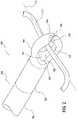
- FIG. 1shows, in schematic perspective view, a surgical tool 100 prepared according to principles of the invention.
- Surgical tool 100includes a handle member 102 , and a cannulated anchor driver 104 (i.e., a hollow cylindrical anchor driver).
- An exemplary anchor, 106is shown as engaged with a spline coupling 108 at a distal end 109 of the cannulated anchor driver 104 .
- the anchor driverwill not include any spline feature, but will include other features or arrangements for coupling to the anchor.
- the anchor driver and anchorwill have complementary helical threads.
- the anchor driver and anchorwill have substantially smooth surfaces retained adjacent to one another by an interference fit.
- an adhesive materialwill retain the anchor driver and anchor in temporary connection to one another.
- a suture guide shaft 110is disposed coaxially within a longitudinal bore of the anchor driver 104 .
- a distal end 109 of the suture guide shaft 110supports a suture guide 112 .
- the suture guide 112includes an optional generally cylindrical portion 114 and a generally toroidal portion 116 .
- the generally toroidal portion 116defines an inner circumference and a normal axis generally transverse to a longitudinal axis of the guide shaft 110 .
- toroidal shape of toroidal portion 116will, in certain embodiments, include a generally circular toroid as illustrated.
- any other shapewill be employed according to the requirements of a particular application.
- the toroidal portionwill have a generally rectangular configuration; in other embodiments a square configuration; in other embodiments any other regular or irregular polygonal configuration; in other embodiments a generally elliptical configuration; in other embodiments a generally oval configuration.
- any shape of suture guidewill be employed where desirable in light of all design considerations.
- a longitudinal displacement of suture guide shaft 110 with respect to the cannulated anchor driver 104is controlled, in part, by a suture guide release button 118 .
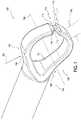
- FIG. 2shows, in schematic perspective view, certain further aspects of a suture guide 200 of a novel surgical tool.
- the illustrated suture guide 200includes a first generally cylindrical portion 202 and a second generally toroidal portion 204 .
- the generally cylindrical portion 202is coupled to a distal end 206 of a suture guide shaft 208 .
- This couplingmay be affected by, for example and without limitation, threads, swaging, soldering, welding and/or an adhesive coupling.
- the cylindrical portion 202 and the suture guide shaft 208are integrally formed as a single structural member.
- the generally toroidal portion 204includes an internal hearing surface region 210 .
- Bearing surface region 210serves to support a portion of a suture 212 as illustrated.
- surface region 210will be more or less arcuate in form, defining (in certain embodiments) a saddle curve such that the surface region curve circumferentially around a generally circular axis of the toroidal portion, where the axis of the toroidal portion defines a plane generally perpendicular to a longitudinal axis of the suture 214 , as depicted.
- a proximal portion 216 of the internal surface region 210includes a region of extended curvature 218 .
- This region of extended curvatureserves to support the suture 212 in sliding relation when the suture is disposed under additional tension so as to allow adjustment of the relative position of the soft and osseous tissues.
- the generally toroidal portion 204 of the suture guide 200embodies a slot 220 defined by first 222 and second 224 surface regions disposed in opposition to one another and generally transverse to the axis of the portal portion.
- slot 220allows the ready insertion of a suture portion 212 into the aperture 226 of the generally toroidal portion 204 , thereby avoiding the need to thread the suture longitudinally through aperture 226 , starting at a first end of the suture, and further allowing removal of the suture guide once the suture is fixed in place.
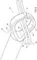
- FIG. 3shows, in schematic cross-section, further aspects of a suture guide 300 prepared according to principles of the invention.
- the illustrated suture guideincludes a first generally cylindrical portion 302 and a second generally toroidal portion 304 .
- a proximal end 306 of the cylindrical portion 302includes a generally circular cylindrical internally threaded bore 308 .
- the generally circular cylindrical internally threaded bore 308defines a longitudinal axis generally coincident with a longitudinal axis 309 of the first generally cylindrical portion 302 .
- the second generally toroidal portion 304includes an internal bearing surface region 310 which serves to support a portion of a suture 312 , as illustrated.
- An axis of rotation 314 of the generally toroidal portion 304is, in the illustrated embodiment, disposed generally perpendicular 315 to the longitudinal axis 309 of the generally cylindrical portion 302 .
- a proximal region 316 of the internal surface region 310includes a region of extended curvature 318 . As discussed above, this region of extended curvature serves to support the suture 312 in sliding relation 313 when the suture is disposed under tension so as to allow adjustment of the relative position of the soft and osseous tissues.
- the generally toroidal portion 304 of the suture guideembodies a slot 320 .
- This slot 320is defined by first 322 and second 324 surface regions disposed in opposition to one another and generally transverse to the axis of the portal portion.
- slot 320allows the ready insertion of a suture portion 312 into the aperture 326 of the generally toroidal portion 304 . This precludes the need to thread the suture longitudinally through aperture 326 , starting at a first end of the suture.
- slot 320allows removal of the suture guide once the suture is fixed in place by insertion of the bone anchor.
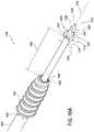
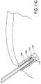
- FIG. 4A and FIG. 4Bshow, in schematic perspective view, a surgical tool prepared according to principles of the invention.
- FIG. 4Ashows the surgical tool in a first extended configuration 400
- FIG. 4Bshows the surgical tool in a second retracted configuration 402 .
- extended configuration 400a suture guide 404 is disposed at a first relatively large distance 406 from a distal end 408 of a bone anchor 410 .
- retracted configuration 402the suture guide 404 is disposed at a second relatively small distance 412 from the distal end 408 of the bone anchor 410 .
- the bone anchor 410is temporarily coupled to, and consequently maintained in a substantially fixed spatial relation to, a cannulated anchor driver 414 .
- the mechanism of this couplingincludes a spline coupling between respective spline features, e.g. 416 , of the cannulated anchor driver 414 and of the bone anchor 410 .
- the suture guide 404 and a suture guide shaft 418are substantially fixedly coupled to one another.
- the suture guide 404 and suture guide shaft 418can be synchronously rotated 420 with respect to the cannulated anchor driver 414 about a longitudinal axis 422 .
- the longitudinal axis 422is substantially common to the suture guide shaft 418 and the cannulated anchor driver 414 .
- the detent mechanismis configured such that the suture guide shaft and anchor driver are rotationally fixed about their mutual longitudinal axis with respect to one another until the detent mechanism is activated. Thereafter, the suture anchor shaft is able to rotate about its longitudinal axis with respect to the anchor driver.
- FIG. 5A - FIG. 5Eillustrate selected states of an exemplary method of employing a surgical tool prepared according to principles of the invention.
- FIG. 5Ashows, in schematic form, a portion of a bone or other substrate medium 502 . Adjacent a surface region 504 of the bone 502 is a portion of a detached ligament 506 . In anticipation of reattachment of the ligament, a bore 508 has been drilled through surface region 504 and into the substrate bone 502 .
- the ligament 506is pierced 510 and a suture 512 is drawn through the ligament as shown.
- Two portions of the suture 514 , 516are disposed through an aperture (e.g., 326 of FIG. 3 ) of a suture guide 518 , the suture guide being disposed at a distal end of a surgical tool 520 .
- the surgical tool 520is configured in an extended configuration (consistent with the arrangement illustrated in FIG. 4A . Consequently a distance 522 between the suture guide 518 and a distal end of a bone anchor 524 is relatively long. Moreover, while the suture anchor is readily rotated about a longitudinal axis with respect to the bone anchor 524 , distance 522 is substantially (though temporarily) fixed.
- That same individualwithout assistance, can then press the release button (element 118 , FIG. 1 ) and release the detent referred to in relation to that release button while concurrently rotating a handle of the surgical tool 520 .
- Rotation of the handlewhich is rotationally fixed with respect to the cannulated anchor driver 540 , and therefore with respect to the bone anchor 524 , causes a corresponding rotation of the bone anchor 524 .
- By combining this rotational motion with an application of longitudinal force 542 extern helical threads on the bone anchor 524can be made to engage with the internal surface of bore 508 and thereby advance the bone anchor 524 into the bore 508 .
- FIGS. 5A-5EWhile a bone anchor 524 exhibiting external helical threads is shown for illustrative purposes in FIGS. 5A-5E , other anchors known in the art, or that may become in the art, may likewise be applied within the scope of the invention. Thus, for example, a barbed anchor, rather than a threaded anchor may be employed. In addition, an anchor may be employed that incorporates neither threads nor barbs, but is fixed within a bore by, for example, an interference fit. Likewise, an elastic retainer, an adhesively retained stopper, or any other retaining device appropriate to the particular circumstances will be applied and considered to be within the scope of the invention.
- this tensionresults in the spline feature of the cannulate anchor driver 540 disengage from the bone anchor 524 and allow the surgical tool 520 to be withdrawn.
- a portion of the suture 552 previously disposed within the aperture 554 of the suture guidepasses through a slot in the suture guide (as illustrated, for example, as element 220 of FIG. 2 ). This allows the suture guide to release the suture portion 552 and permits the withdrawal of the surgical tool 520 describe above.
- FIG. 6shows, in flowchart form, certain portions of a method 600 for using a surgical tool according to principles of the invention.
- the methodincludes determining a ligament fixation location 602 with respect to an underlying substrate such as bone and drilling an anchor bore in the bone 604 to receive a bone anchor and a length of suture.
- a length of sutureis coupled to a ligament or other soft tissue by, for example, threading through the tissue with a needle 606 .
- a portion of the sutureis coupled to a suture guide by, for example, threading the suture through an aperture of a generally toroidal region the suture guide 608 .
- the suture guide and sutureare manipulated, with the application of appropriate pressure and tension (as would be understood by one of skill in the art) to insert the extended suture guide 612 into the bore drilled at step 604 . Further application of pressure to the suture guide and tension on the suture, as well as direct manipulation of the soft tissue and underlying substrate allows finalization of the ligament location with respect to the bone 614 .
- a release mechanism of the surgical toolWhile holding the suture in place, a release mechanism of the surgical tool is activated. This release mechanism releases a detent that couples the suture guide to a balance of the surgical tool 616 . This release of the detent mechanism allows the surgical tool to advance a bone anchor supported by the surgical tool to be advanced 618 towards and into a mouth of the bore prepared at step 604 . In certain embodiments of the invention, the bone anchor will contact the underlying bone and even be advanced by rotation or pressure into the bore before any release of the detent mechanism.
- Rotation of a handle of the surgical toolconveys a torque through the handle, through an anchor driver, through a spline feature and into the bone anchor so that the bone anchor threads engage an internal surface region of the bore 620 . Further rotation of the handle advances the bone anchor into the bore until the anchor is fully inserted at its destination 622 .
- the handle of the surgical toolis withdrawn, disengaging the spline coupling from the now-inserted bone anchor.
- the portion of the suture that was disposed within the suture guidepasses through a slot in the suture guide 624 . This allows complete withdrawal of the surgical tool and leaves the suture compressed and fixed to the internal surface of the bore by the inserted bone anchor.
- FIG. 7shows, in schematic perspective view, a further suture guide 700 for a surgical tool prepared according to principles of the invention.
- the suture guide 700includes a generally toroidal portion 702 with an internal bearing surface region 704 .
- An internal circumferential bearing surface region 704defines an aperture 706 about and transverse to an axis 708 . As discussed above in relation to suture guide 200 , the bearing surface region 704 serves to enclose a portion of a suture (not shown) disposed within and through aperture 706 .
- surface region 704 of suture guide 700forms a contiguous surface region throughout 360° about axis 708 .
- surface 704 of suture guide 700is circumferentially continuous across region 710 .
- the suture guideis relieved 712 , 714 in the vicinity of region 710 so that a dimension 716 of surface region 704 in the vicinity of 710 is relatively small in the direction of axis 708 as compared with a corresponding dimension elsewhere, e.g. 718 , around the aperture 706 .
- the reduced internal circumferential surface region 720will, in certain embodiments, include a frangible region, such that the application of certain forces, e.g. 722 , 724 , to corresponding external surface regions, e.g. 726 , 728 , results in a distortion of the cross-sectional shape of aperture 706 and, consequently, fracturing of the frangible portion to form an aperture in the vicinity of region 720 .
- the requisite forces 722 , 724will, in certain embodiments, be applied to surface regions 726 , 728 respectively, by corresponding distal surface regions of a bone anchor.
- FIG. 7embodies a plurality of polygonal regions.
- suture guides illustratedare intended to be equivalent in terms of their defining curvatures.
- the actual curvature of the device, as prepared,may embody smooth curves, polygonal sections, and any combination thereof according to the particular circumstances to be addressed.
- FIGS. 8A-8Dshows, in schematic cross-section, a portion of a surgical tool 800 prepared according to principles of the invention.
- the surgical toolincludes a cannulated anchor driver 802 temporarily slidingly coupled to a bone anchor 804 by complementary spline features 806 of the cannulated anchor driver 802 and bone anchor 804 respectively.
- Disposed within a cannula 807 of the cannulated anchor driver 802is a portion of a suture guide shaft 808 .
- a suture guide 810is coupled to a distal end 812 of the suture guide shaft 808 .
- surgical tool 800is shown in an extended configuration 820 where the suture guide 810 is disposed at a first relatively large distance 818 from a distal end 822 of the bone anchor 804 .
- the suture guide 810includes an aperture 814 .
- an internal circumferential bearing surface region 816is initially contiguous around the circumference of aperture 814 .
- the surgical tool 800is applied generally according to the method 600 described above with respect to FIG. 6 .
- FIG. 8Bshows surgical tool 800 in a second intermediate configuration 824 .
- the suture guide 810is disposed at a second relatively small distance 826 from distal end 822 of the bone anchor 804 .
- distal end 822 of suture guide 804is disposed in contact with an external circumferential surface region 830 of the suture guide 810 .
- FIG. 8Cshows surgical tool 800 in a third intermediate configuration 832 .
- the suture guide 810is disposed at a still smaller distance 834 from distal end 822 of the bone anchor 804 .
- the readerwill observe that interference between distal end 822 of the bone anchor has interfered with external surface region 830 of the suture guide 810 . Consequently, the suture guide 810 has been distorted, elongating aperture 814 , and causing a frangible region 836 of suture guide 810 to fracture.
- the resulting opening 838 of the suture guide aperture 814allows the suture guide to be withdrawn from a portion of a suture captured by the suture anchor 804 .
- FIG. 8Dshows surgical tool 800 in a fourth retracted configuration where the suture guide 810 is fully retracted within the cannula 807 of the cannulated anchor driver 802 . Accordingly, the surgical tool 800 can be withdrawn from the suture anchor 804 , disengaging the spline features 806 of the cannulated anchor driver 802 from the bone anchor 804 , and leaving the bone anchor and suture secured in substrate bone.
- a suture guideis detachably coupled to a suture guide shaft.
- the suture guidemay, for example, have a contiguous internal circumferential surface.
- the suture guidedoes not include a frangible portion. Rather, the suture guide is arranged and configured to be released from the suture guide shaft in response to an interference between the suture guide and a distal end 822 of the bone anchor, so that the suture guide is left behind in the bore when suture guide shaft is withdrawn.
- an interface between the suture guide and the suture guide shaftmay be a smooth interference fit, or may include frangible features such as frangible threads, frangible barbs, frangible ribs, a frangible adhesive, or any other arrangement effective to achieve a temporary, but releasable coupling between the suture guide shaft and the suture guide.
- the suture guidewill pass into and through a bore in the anchor, but not through a cannula or bore of the anchor driver.
- FIG. 9shows, in cutaway perspective view, a portion of a further surgical tool 900 prepared according to principles of the invention including a suture guide 902 .
- Suture guide 902includes a generally toroidal portion 904 with an internal circumferential bearing surface 906 .
- Internal circumferential bearing surface 906serves to support a portion of a suture 908 , 910 during, e.g., an arthroscopic surgery in the manner generally described above.
- the toroidal portion 904 of suture guide 902includes first 912 and second 914 generally radial internal surface regions.
- Surface regions 912 and 914are initially disposed in generally parallel spaced relation to one another and either in contact with one another, or sufficiently proximate to one another to prevent egress of the suture portions 908 , 910 from within an aperture 916 of the suture guide 902 .
- the generally toroidal portion 904 of the suture guide 902exhibits a geometry that, together with materials characteristic of the suture guide 902 , serve to maintain surfaces 912 and 914 in proximity to one another when the suture guide 902 is in a relaxed state.
- the suture guidetends to deform. This deformation tends to displace surfaces 912 and 914 away from one another, opening the suture guide and allowing it to be released from the suture portions 908 and 910 .
- the toroidal portion 904 of the suture guide 902will include a generally elastic material having a spring characteristic that, along with the geometry of the suture guide 902 , tends to maintain surfaces 912 and 914 in proximity to one another until the suture guide 902 is deformed. In such an embodiment, the deformation will be more or less elastic.
- the toroidal portion 904 of the suture guide 902will include a generally inelastic malleable material having a characteristic that, along with the geometry of the suture guide 902 , tends to maintain surfaces 912 and 914 in proximity to one another until the suture guide 902 is deformed.
- the deformationwill be generally inelastic.
- the suture guidewill be detachable from the suture guide shaft such that, after insertion of the anchor, when the suture guide shaft is withdrawn, the suture guide is detached from the suture guide shaft and remains within the bore in the substrate underneath the anchor.
- FIG. 10Ashows, in cutaway perspective view, a further surgical tool 1000 prepared according to principles of the invention.
- exemplary surgical tool 1000includes a cannulated anchor driver 1002 coupled through spline features 1004 to a bone anchor 1006 .
- a shaft 1008Disposed within and through a longitudinal cannula of the cannulated anchor driver 1002 and the bone anchor 1006 is a shaft 1008 .
- the shaft 1008defines a longitudinal axis 1010 .
- a generally toroidal bearing washer 1014is disposed coaxially about the shaft 1008 .
- the generally toroidal bearing washeris supported on shaft 1008 by a snug but slidable interface 1016 between an internal circumferential surface of the washer 1014 and a corresponding external circumferential surface of the shaft 1008 .
- a cross-section of the shaft 1008is circular. It will be appreciated, however, by one of skill in the art, that in any of the embodiments disclosed in this application, other cross-sections are contemplated to be within the scope of the invention. Such other cross-sections will include, in various embodiments and without limitation, polygonal, elliptical and otherwise arcuate cross-sections.
- a first relatively proximal circumferential surface region 1018 of the shaft 1008has a relatively large diameter 1020 .
- a second relatively distal circumferential surface region 1022 of the shaft 1018has a relatively small diameter 1024 .
- a generally radial surface region 1026 disposed between surface region 1018 and surface region 1022defines a shoulder further supporting the washer 1014 and limiting its motion in a proximal direction along longitudinal axis 1010 by mechanical interference.
- a distal extremity 1028 of shaft 1008tapers to a point 1030 .
- This taperis defined by an intermediate surface region between circumferential surface region 1022 and point 1030 .
- the surgical tool 1000is shown in an extended configuration such that distance 1034 between washer 1014 and a distal end 1036 of bone anchor 1006 is relatively long, as compared to the corresponding dimension of the same surgical tool when disposed in a retracted configuration.
- a retracted configurationis illustrated in FIG. 10B .
- washer 1014is disposed relatively proximate to distal end 1036 of bone anchor 1006 and distance 1038 is consequently relatively short.
- FIGS. 11A-11Hshow, in schematic cross-sectional view, various states in an exemplary method of using a surgical tool 1100 similar to tool 1000 of FIGS. 10A and 10B .
- FIG. 11Ashows surgical tool 1100 , a portion of a detached tendon 1102 and a portion of a bony substrate 1104 where the tendon is to be reattached.
- a bore 1106has been prepared in the bony substrate to receive a portion of the tendon and a bone anchor 1108 .
- a distal end 1110 of the surgical toolis pointed for piercing, and that a circumferential external surface 1112 of a shaft 1114 of the surgical tool 1100 (or of a separate tip on the shaft 1114 ) supports a corresponding internal surface 1116 of a bearing washer 1118 .
- the bearing washer 1118is prevented from moving proximally along shaft 1114 by a shoulder feature 1120 , and that the surgical tool 1100 is disposed in an extended configuration (as discussed in relation to FIGS. 10A-10B ).
- FIG. 11Bshows that the surgical tool 1100 has been advanced so that distal end 1110 has pierced the tendon 1102 .
- tool 1100is urged forward longitudinally until a distal surface region 1122 of bearing washer 1118 contacts a corresponding surface region 1124 of tendon 1102 .
- FIG. 11Cshows that surgical tool 1100 has been rotated 1126 about an axis transverse to longitudinal axis 1128 of shaft 1114 , and advanced 1130 towards the prepared bore 1106 .
- Tendon 1102is consequently moved with respect to bony substrate 1104 and stretched towards a desired attachment location.
- surgical tool 1100is counter-rotated 1132 to bring longitudinal axis 1128 generally into alignment with a longitudinal axis of bore 1106 .
- surgical tool 1100is advanced with a generally linear motion in direction 1134 along longitudinal axis 1128 to draw a portion 1136 of tendon 1102 into and towards the bottom surface 1140 of bore 1106 , as shown in FIG. 11E .
- a detent of the surgical toolis released. This allows relative longitudinal displacement of the bone anchor 1108 in direction 1134 with respect to the substrate bone 1104 and the washer 1118 .
- FIG. 11Fshows a state of the surgical tool, in which a distal end 1141 of the bone anchor 1108 has been advanced into contact with a proximal edge 1142 of bore 1106 (i.e., the mouth of the bore), and into contact with a surface region 1144 the tendon 1102 .
- Thisbrings helical threads e.g., 1146 , of the bone anchor 1108 into an arrangement where rotation of the bone anchor 1108 about longitudinal axis 1128 causes the threads of the bone anchor to further engage with the surrounding bone and soft tissue so as to advance the bone anchor towards the bottom 1140 of the bore 1106 .
- FIG. 11Gshows a condition of the assembly once the bone anchor 1108 has been rotated until fully driven into the bore 1106 , such that the distal end 1141 of the bone anchor 1108 is disposed in contact with a proximal surface region 1148 of bearing washer 1118 . Thereafter, as shown in FIG. 11H , the surgical tool may be withdrawn in direction 1150 along longitudinal axis 1128 .
- a surgical toolsuch as surgical tool 1100 ( FIG. 11 ) is configured to be employed by passing a share through soft tissue 1102 , and wrapping the suture around a circumferential external surface 1112 of shaft 1114 . The suture is then urged into bore 1106 and fixed in place by the application of the anchor 1108 .
- FIG. 12shows, in exploded perspective view, an exemplary surgical tool 1200 prepared according to principles of the invention.
- the surgical tool 1200includes a handle member 1202 .
- the handle member 1202is substantially fixedly coupled to a cannulated anchor driver 1204 such that a longitudinal axis of the handle member and a longitudinal axis of the cannulated anchor driver are substantially coincident.
- the cannulated anchor driver 1204includes, on an external circumferential surface of its distal end, a spline feature 1206 .
- the spline feature 1206is sized and arrange to couple with, and be complementary to, an internal spline feature of a bone anchor 1208 .
- the bone anchor 1208is shown as having an external helical thread for engaging with an internal circumferential surface of a bore in a substrate.
- any of the bone anchors presented in this applicationneed not be helically threaded, but may include any of a wide variety of bone anchors including, for example and without limitation, a barbed bone anchor, an adhesively mounted bone anchor, and any combination thereof.
- a suture guide shaft 1210Disposed within a longitudinal cannula (or bore) of the cannulated anchored driver 1204 is a suture guide shaft 1210 .
- the suture guide shaftis substantially fixedly coupled, at a distal end thereof, to a suture guide 1212 .
- the suture guideincludes, at its distal end, a generally toroidal feature 1214 such as, for example, an eyelet.
- the toroidal featuredefines an aperture 1216 with an internal bearing surface region for encircling and controlling a portion of a suture or other material.
- the longitudinal axis of the suture guide shaft 1210lies generally within a plane of the aperture 1216 .
- a longitudinal axis of the aperture through the plane of the apertureis disposed generally transverse to the longitudinal axis of the suture guide shaft 1210 .
- the suture guide shaft 1210When the suture guide shaft 1210 is in use, it is disposed within the cannula of the cannulated anchor driver 1204 , such that the cannulated anchor driver at the suture guide shaft are arranged generally coaxial to one another.
- the suture guide shaft 1210includes, near its distal end, an externally threaded coupling feature 1218 and suture guide support shoulder 1217 . These serve to substantially fixedly couple the suture guide shaft 1210 to the suture guide 1212 .
- the suture guide shaft 1210 and suture guide 1212will be coupled in any effective way known, or that becomes known, in the art.
- the suture guide shaft 1210 and suture guide 1212will be integrally formed as a single component.
- a detent mechanism 1219 of the surgical tool 1200include a release button member 1220 , having a generally planar upper surface region 1221 and a detent shaft 1222 with a generally cylindrical external surface region.
- a detent shaft relief feature 1224describes a recess formed in the detent shaft 1222 .
- the release button member 1220also includes a suture guide shaft aperture 1226 disposed through the detent shaft 1222 within the detent shaft relief feature 1224 and generally transverse to a longitudinal axis of the release button member 1220 .
- the handle member 1202includes a detent shaft aperture 1228 with the longitudinal axis generally transverse to the longitudinal axis of file surgical tool handle member 1202 .
- the detent shaft aperture 1228is configured to receive the detent shaft 1222 slidingly therewithin.
- a detent spring 1230is sized and configured to be disposed within a recess 1232 arranged within the handle member 1202 coaxially around detent shaft aperture 1228 .
- the detent shaft 1222is sized and configured to be disposed within an internal region defined by the detent spring 1230 .
- the illustrated detent spring 1230is shown as a plurality of Belleville washers.
- One of skill in the artwill appreciate that other configurations, including any spiral spring, elastomeric tube, or other elastic member will be used in corresponding embodiments of the invention according to the requirements of a particular application.
- the recess 1232is defined by an internal surface region of a suture guide release button relief 1234 , such that the release button member 1220 can move radially into the handle b compression of spring 1230 when an inward radial force is applied to upper surface region 1221 .
- a detent shaft retainer fastener 1236is configured to be coupled to a lower end of the release button member 1220 (e.g., by a threaded coupling, a weldment, a chemical adhesive, etc.) so as to retain the release button member 1220 and detent spring 1230 in place.
- the suture guide shaft 1210includes first 1238 and second 1240 capture relief features near a proximal end of the suture guide shaft.
- the suture guide shaft 1210also includes a tapered feature 1242 immediately adjacent its proximal end.
- first 1238 and second 1240 capture relief featuresare arranged and configured to be releasably captured at the detent shaft relief feature 1224 when the suture guide shaft 1210 is disposed within the suture guide shaft aperture 1226 of the detent shaft 1222 .
- a further sheath 1250is disposed coaxially around the outside of cannulated anchor driver 1204 .
- FIG. 13shows, in cross-section, a portion of an exemplary surgical tool 1300 prepared according to principles of the invention.
- Surgical tool 1300includes a handle member 1302 with a detent shaft aperture 1304 .
- a detent member 1305 including a detent shaft 1306is disposed coaxially within the detent shaft aperture 1304 .
- a cannulated anchor driver 1308is substantially fixedly disposed coaxially within a further bore 1309 of the handle member 1302 .
- a suture guide shaft 1311Slidingly disposed within a cannula 1310 of the cannulated anchor driver 1308 is a suture guide shaft 1311 .
- the guide shaftis relieved at two locations along its length; an extended guide shaft relief 1312 , and a retracted guide shaft relief 1314 .
- the guide shaftis adapted to be arrested in its longitudinal motion by a detent mechanism of the handle at either of the extended guide shaft relief 1312 and the retracted guide shaft relief 1314 .
- the suture guide shaft 1311is rotatable within the cannula 1310 when captured by the detent mechanism at both of the extended configuration and the retracted configuration. That is, the handle member 1302 can be co-rotated with the cannulated anchor driver 1308 about a longitudinal axis common to the handle, the cannulated anchor driver 1308 and the suture guide shaft 1311 while the suture guide shaft 1311 remains static and does not rotate.
- the cross-sections of the suture guide shaft 1311 and both the extended 1312 and retracted 1314 reliefs of the suture guide shaftare substantially circular.
- the detent mechanismis arranged to prevent rotation of the suture guide with respect to the cannulated anchor driver until the detent mechanism is released.
- the detent member 1305includes a suture guide release button 1316 .
- One end of a detent spring 1318is located proximal to a lower surface 1319 of the suture guide release button 1316 .
- An opposite end of the detent spring 1318is supported by a detent spring shoulder 1320 .
- the detent spring 1318is arranged to urge the lower surface 1319 of the suture guide release button 1316 away from the detent spring shoulder 1320 . This motion is limited by a detent shaft retainer fastener 1322 in a manner that will be evident to one of skill in the art.
- Detent shaft 1306includes a detent shaft aperture 1328 which is located substantially perpendicular to a longitudinal axis 1330 of the detent shaft 1306 .
- the detent spring 1318tends to maintain circumferential edges 1324 , 1326 of the detent shaft aperture 1328 in contact with corresponding edge regions of the guide shaft reliefs 1312 , 1314 so as to temporarily substantially fix the longitudinal position of the suture guide shaft 1311 with respect to the handle 1302 and cannulated anchor driver 1308 .
- a proximal end 1332 of the suture guide shaft 1311includes a generally conically tapered region 1334 .
- This conically tapered region 1334facilitates initial insertion of the suture guide shaft 1311 into the apparatus and past edge 1324 of the detent shaft aperture 1328 .
- FIG. 14shows, in schematic perspective view, another aspect of a surgical tool 1400 prepared according to principles of the invention.
- the surgical tool 1400includes a handle member 1402 .
- Disposed within the handle member 1402is a detent mechanism 1404 .
- a longitudinal axis 1406is common to the handle member 1402 , a cannulated anchor driver 1408 and a suture guide shaft 1410 disposed within a cannula of the cannulated anchor driver 1408 .
- the detent mechanism 1404includes a detent member 1412 with a suture guide release button 1414 a detent shaft 1416 detent spring 1418 and a suture guide aperture 1420 .
- the suture guide aperture 1420embodies edges 1422 that interfere with and temporarily capture corresponding edges e.g., 1424 , 1426 of an extended suture guide relief 1428 , and a retracted suture guide relief (not visible).
- detent spring 1418 of surgical tool 1400is disposed relatively distal to release button 1414 of detent member 1412 , as compared to detent spring 1318 and release button 1316 .
- Handle member 1402also includes first 1430 and second 1432 distal jaw members. Distal jaw members 1430 and 1432 are disposed within respective recesses 1434 , 1436 of handle member 1402 . The jaw members 1430 and 1432 have respective contact surface regions 1438 , 1440 . In the illustrated embodiment, cannulated anchor driver 1408 includes jaw apertures, e.g. 1442 .
- distal jaw members 1430 and 1432tend to impinge within the jaw apertures, e.g. 1442 , to retain cannulated anchor driver 1408 longitudinally and rotationally in place within the handle member 1402 .
- cannulated anchor driver 1408may be removably installed within handle member 1402 and securely retained therein during operation of the surgical tool 1400 .
- the contact surface regions 1438 and 1440are arranged to impinge on an external circumferential surface region of suture guide shaft 1410 , thereby providing a desirable resistance to rotation of the suture guide shaft 1410 with respect to handle member 1402 while still allowing the suture guide shaft to rotate.
- the distal jaw members 1430 and 1432include one or more of an elastomeric polymer material, a thermoplastic polymer material, a thermoset polymer material, and a metallic material. In other embodiments, other materials will be employed to achieve desirable characteristics to achieve the functions described above.
- a method according to principles of the inventionincludes:
Landscapes
- Health & Medical Sciences (AREA)
- Life Sciences & Earth Sciences (AREA)
- Surgery (AREA)
- Heart & Thoracic Surgery (AREA)
- Engineering & Computer Science (AREA)
- Biomedical Technology (AREA)
- Nuclear Medicine, Radiotherapy & Molecular Imaging (AREA)
- Medical Informatics (AREA)
- Molecular Biology (AREA)
- Animal Behavior & Ethology (AREA)
- General Health & Medical Sciences (AREA)
- Public Health (AREA)
- Veterinary Medicine (AREA)
- Rheumatology (AREA)
- Surgical Instruments (AREA)
Abstract
Description
- 1. Place sutures through the targeted tissue as required.
- 2. Create a hole to accommodate the selected diameter anchor to the proper depth using a purpose designed drill bit and guide. The guide may or may not be required.
- 3. Aseptically open the driver and anchor and place the anchor onto the driver.
- 4. Thread previously placed sutures placed through the Suture Guide located on the distal end of the driver.
- 5. Insert the Suture Guide with handle into the hole created in step 2.
- 6. Remove any slack in the suture and create the desired amount of tension by pulling on the suture tails.
- 7. Push the handle with the anchor firmly into the hole, until the anchor contacts the suture. This action will maintain the desired tension on the suture.
- 8. Depress the button on the handle and begin to insert the anchor into the hole by turning the handle in a clockwise direction.
- 9. Continue insertion until an audible “click” is heard. This will signal the proper depth of the implant, which should be slightly below the surface of the surrounding bone.
- 10. Remove the handle from the implant by pulling it along the axis of insertion.
- 11. Trim the access suture tails as desired.
Claims (19)
Priority Applications (5)
| Application Number | Priority Date | Filing Date | Title |
|---|---|---|---|
| US16/206,736US11457912B2 (en) | 2016-06-02 | 2018-11-30 | Suture tool and method of use |
| US16/551,705US11517301B2 (en) | 2016-06-02 | 2019-08-26 | Surgical tool and method of use |
| US17/958,391US12274436B2 (en) | 2016-06-02 | 2022-10-01 | Suture tool and method of use |
| US17/981,046US12419630B2 (en) | 2016-06-02 | 2022-11-04 | Surgical tool and method of use |
| US19/178,359US20250248704A1 (en) | 2016-06-02 | 2025-04-14 | Suture tool and method of use |
Applications Claiming Priority (4)
| Application Number | Priority Date | Filing Date | Title |
|---|---|---|---|
| US201662344489P | 2016-06-02 | 2016-06-02 | |
| US201662368023P | 2016-07-28 | 2016-07-28 | |
| PCT/US2017/035792WO2017210620A1 (en) | 2016-06-02 | 2017-06-02 | Suture tool and method of use |
| US16/206,736US11457912B2 (en) | 2016-06-02 | 2018-11-30 | Suture tool and method of use |
Related Parent Applications (1)
| Application Number | Title | Priority Date | Filing Date |
|---|---|---|---|
| PCT/US2017/035792ContinuationWO2017210620A1 (en) | 2016-06-02 | 2017-06-02 | Suture tool and method of use |
Related Child Applications (2)
| Application Number | Title | Priority Date | Filing Date |
|---|---|---|---|
| US16/551,705Continuation-In-PartUS11517301B2 (en) | 2016-06-02 | 2019-08-26 | Surgical tool and method of use |
| US17/958,391ContinuationUS12274436B2 (en) | 2016-06-02 | 2022-10-01 | Suture tool and method of use |
Publications (2)
| Publication Number | Publication Date |
|---|---|
| US20190090868A1 US20190090868A1 (en) | 2019-03-28 |
| US11457912B2true US11457912B2 (en) | 2022-10-04 |
Family
ID=60479125
Family Applications (3)
| Application Number | Title | Priority Date | Filing Date |
|---|---|---|---|
| US16/206,736Active2037-06-04US11457912B2 (en) | 2016-06-02 | 2018-11-30 | Suture tool and method of use |
| US17/958,391Active2037-12-24US12274436B2 (en) | 2016-06-02 | 2022-10-01 | Suture tool and method of use |
| US19/178,359PendingUS20250248704A1 (en) | 2016-06-02 | 2025-04-14 | Suture tool and method of use |
Family Applications After (2)
| Application Number | Title | Priority Date | Filing Date |
|---|---|---|---|
| US17/958,391Active2037-12-24US12274436B2 (en) | 2016-06-02 | 2022-10-01 | Suture tool and method of use |
| US19/178,359PendingUS20250248704A1 (en) | 2016-06-02 | 2025-04-14 | Suture tool and method of use |
Country Status (2)
| Country | Link |
|---|---|
| US (3) | US11457912B2 (en) |
| WO (1) | WO2017210620A1 (en) |
Families Citing this family (13)
| Publication number | Priority date | Publication date | Assignee | Title |
|---|---|---|---|---|
| US11109937B2 (en)* | 2018-01-12 | 2021-09-07 | Homayoun H. Zadeh | Instruments and methods for subperiosteal tunneling and related surgical procedures |
| US10820915B2 (en)* | 2018-03-06 | 2020-11-03 | Medos International Sarl | Methods, systems, and devices for instability repair |
| USD1034988S1 (en)* | 2019-09-17 | 2024-07-09 | Healthium Medtech Limited | Knotless anchor |
| USD933221S1 (en)* | 2019-09-17 | 2021-10-12 | Helathium MedTech Ltd. | Knotless anchor |
| USD933222S1 (en)* | 2019-09-17 | 2021-10-12 | Helathium MedTech Ltd. | Knotless anchor |
| US12256918B2 (en)* | 2020-01-08 | 2025-03-25 | Arthrex, Inc. | Inserter assembly with suture protector tubing and method of use |
| WO2021222172A2 (en)* | 2020-04-29 | 2021-11-04 | DePuy Synthes Products, Inc. | Knotless anchor insertion |
| USD953530S1 (en)* | 2020-06-18 | 2022-05-31 | Bfm Holdings, Llc | Surgical drill bit |
| USD1028232S1 (en) | 2021-04-27 | 2024-05-21 | Medos International Sarl | Suture anchor insertion device |
| USD1019945S1 (en) | 2021-12-30 | 2024-03-26 | Medos International Sarl | Suture anchor insertion device |
| US12137894B2 (en)* | 2021-12-30 | 2024-11-12 | Medos International Sarl | Knotless anchor inserter tool extraction |
| US12096926B2 (en) | 2022-01-12 | 2024-09-24 | Medos International Sarl | Knotless anchor temporary suture capture |
| WO2024246761A1 (en)* | 2023-05-31 | 2024-12-05 | Universita' Degli Studi Di Torino | Kit for reversible and modular hemostatic ligation of uterine vessels |
Citations (212)
| Publication number | Priority date | Publication date | Assignee | Title |
|---|---|---|---|---|
| US5203787A (en) | 1990-11-19 | 1993-04-20 | Biomet, Inc. | Suture retaining arrangement |
| US5207679A (en) | 1991-09-26 | 1993-05-04 | Mitek Surgical Products, Inc. | Suture anchor and installation tool |
| US5527316A (en) | 1994-02-23 | 1996-06-18 | Stone; Kevin T. | Surgical reamer |
| US5578036A (en) | 1993-12-06 | 1996-11-26 | Stone; Kevin T. | Method and apparatus for fixation of bone during surgical procedures |
| US5591207A (en)* | 1995-03-30 | 1997-01-07 | Linvatec Corporation | Driving system for inserting threaded suture anchors |
| US5660091A (en) | 1996-02-06 | 1997-08-26 | Walter Lorenz Surgical, Inc. | Blunt-nosed, self-retaining screwdriver |
| US5690631A (en) | 1996-09-11 | 1997-11-25 | Walter Lorenz Surgical, Inc. | Multi-configurable plating system |
| US5702396A (en) | 1995-03-27 | 1997-12-30 | Hoenig; Johannes Franz | Osteosynthesis plate |
| US5732821A (en) | 1995-09-28 | 1998-03-31 | Biomet, Inc. | System for sterilizing medical devices |
| US5792143A (en) | 1997-04-21 | 1998-08-11 | Biomet, Inc | Neck length measuring device and method of using same for implanting a hip prosthesis |
| US5948000A (en) | 1996-10-03 | 1999-09-07 | United States Surgical Corporation | System for suture anchor placement |
| US6024759A (en) | 1998-05-08 | 2000-02-15 | Walter Lorenz Surgical, Inc. | Method and apparatus for performing pectus excavatum repair |
| US6129728A (en) | 1998-02-18 | 2000-10-10 | Walter Lorenz Surgical, Inc. | Method and apparatus for mandibular osteosynthesis |
| US6325803B1 (en) | 1998-02-18 | 2001-12-04 | Walter Lorenz Surgical, Inc. | Method and apparatus for mandibular osteosynthesis |
| US6364910B1 (en) | 2001-07-11 | 2002-04-02 | Biomet, Inc. | Method and apparatus for use of a glenoid component |
| US20020115999A1 (en) | 1999-07-23 | 2002-08-22 | Mcdevitt Dennis | System and method for attaching soft tissue to bone |
| US20020128654A1 (en) | 1998-02-18 | 2002-09-12 | Steger Shon D. | Method and apparatus for bone fracture fixation |
| US6471706B1 (en) | 2000-04-18 | 2002-10-29 | Walter Lorenz Surgical, Inc. | Resorbable bone distractor and method |
| US20030028253A1 (en) | 2001-07-11 | 2003-02-06 | Stone Kevin T. | Shoulder prosthesis |
| US20030125743A1 (en) | 2001-09-25 | 2003-07-03 | Roman Shawn David | Cranial clamp and method for fixating a bone plate |
| US6616673B1 (en) | 2001-04-19 | 2003-09-09 | Biomet, Inc. | Segmented joint distractor |
| US6641597B2 (en) | 2001-05-25 | 2003-11-04 | Arthrex, Inc. | Interference fit knotless suture anchor fixation |
| US20030208276A1 (en) | 2000-07-18 | 2003-11-06 | Berelsman Brian K. | Elbow prosthesis |
| US6746486B1 (en) | 2002-10-24 | 2004-06-08 | Biomet, Inc. | Method and apparatus for total wrist angled back carpal plate |
| US20040153161A1 (en) | 2003-02-04 | 2004-08-05 | Stone Kevin T. | Humeral stem with anatomical location of taper access for fixation of humeral head |
| US6783549B1 (en) | 2001-07-27 | 2004-08-31 | Biomet, Inc. | Modular humeral head resurfacing system |
| US20040254646A1 (en) | 2003-06-16 | 2004-12-16 | Stone Kevin T. | Provisional coupling mechanism |
| US20040260298A1 (en) | 2003-06-18 | 2004-12-23 | Kaiser Ryan A. | Device and method of fastening a graft to a bone |
| US20050107882A1 (en) | 2001-07-27 | 2005-05-19 | Stone Kevin T. | Modular humeral head resurfacing system |
| US20050119696A1 (en) | 2003-12-02 | 2005-06-02 | Walters Troy M. | Braided suture |
| US20050273003A1 (en) | 2003-10-15 | 2005-12-08 | Arthrotek, Inc. | Method and apparatus for graft fixation |
| US20050277961A1 (en) | 2004-06-09 | 2005-12-15 | Arthrotek, Inc. | Method and apparatus for soft tissue fixation |
| US20060020344A1 (en) | 2002-07-10 | 2006-01-26 | Biomet Manufacturing Corp. | Shoulder implant assembly |
| US20060029633A1 (en) | 2004-08-03 | 2006-02-09 | Arthrotek, Inc | Biological patch for use in medical procedures |
| US20060036330A1 (en) | 2002-10-24 | 2006-02-16 | Biomet Manufacturing Corp. | Method and apparatus for wrist arthroplasty |
| US20060100627A1 (en) | 2004-11-09 | 2006-05-11 | Arthrotek, Inc. | Tissue fixation device |
| US20060111729A1 (en) | 2004-11-23 | 2006-05-25 | Arthrotek, Inc. | Method and apparatus for manipulating bone during a surgical procedure |
| US20060189993A1 (en) | 2004-11-09 | 2006-08-24 | Arthrotek, Inc. | Soft tissue conduit device |
| US20060190042A1 (en) | 2004-11-05 | 2006-08-24 | Arthrotek, Inc. | Tissue repair assembly |
| US20060235413A1 (en) | 2004-12-07 | 2006-10-19 | Arthrotek, Inc. | Expanding suture anchor having an actuator pin |
| US20060247642A1 (en) | 2004-11-09 | 2006-11-02 | Stone Kevin T | Tissue fixation device |
| US20060282085A1 (en) | 2004-11-09 | 2006-12-14 | Arthrotek, Inc. | Soft tissue conduit device |
| US7175663B1 (en) | 2003-10-08 | 2007-02-13 | Biomet Manufacturing Corp. | Shoulder implant assembly |
| US20070038299A1 (en) | 2005-08-12 | 2007-02-15 | Arthrotek, Inc | Multilayer microperforated implant |
| US20070038230A1 (en) | 2005-08-11 | 2007-02-15 | Arthrotek, Inc. | Steerable suture passing device |
| US20070049944A1 (en) | 2004-06-09 | 2007-03-01 | Arthrotek, Inc. | Method and apparatus for soft tissue fixation |
| US7217246B1 (en) | 2004-06-17 | 2007-05-15 | Biomet Sports Medicine, Inc. | Method and apparatus for retaining a fixation pin to a cannula |
| US20070141110A1 (en) | 2004-12-09 | 2007-06-21 | Biomet Sports Medicine, Inc. | Continuous phase compositions for ACL repair |
| US20070156174A1 (en) | 2006-01-03 | 2007-07-05 | Arthrotek, Inc. | Method and apparatus for repairing a meniscus |
| US20070179624A1 (en) | 2006-02-02 | 2007-08-02 | Biomet Manufacturing Corp | Method and apparatus for performing a shoulder implant procedure |
| US20070179510A1 (en) | 2006-02-02 | 2007-08-02 | Arthrotek, Inc. | Method and apparatus for passing a flexible strand |
| US7252832B1 (en) | 2004-12-13 | 2007-08-07 | Biomet Sports Medicine, Inc. | Composite collagen material and method of forming same |
| US20070185532A1 (en) | 2006-02-03 | 2007-08-09 | Arthrotek, Inc. | Soft tissue repair assembly and associated method |
| US20070191853A1 (en) | 2006-02-02 | 2007-08-16 | Arthrotek, Inc. | Method and apparatus for performing ACL reconstruction |
| US20070208294A1 (en) | 2004-06-17 | 2007-09-06 | Biomet Sports Medicine, Inc. | Method And Apparatus For Retaining A Fixation Pin To A Cannula |
| US20070225719A1 (en) | 2006-03-21 | 2007-09-27 | Stone Kevin T | Method and apparatuses for securing suture |
| US20070225735A1 (en) | 2006-03-21 | 2007-09-27 | Stone Kevin T | Method and apparatus for passing a suture |
| US7323012B1 (en) | 2004-03-17 | 2008-01-29 | Biomet Manufacturing Corp. | Ankle implant |
| US20080027446A1 (en) | 2006-02-03 | 2008-01-31 | Biomet Sports Medicine, Inc. | Soft Tissue Repair and Conduit Device |
| US7329272B2 (en) | 2000-06-22 | 2008-02-12 | Arthrex, Inc. | Graft fixation using a plug against suture |
| US7331982B1 (en) | 2003-09-08 | 2008-02-19 | Biomet Sports Medicine, Inc. | Suture anchor and associated method |
| US7341592B1 (en) | 2003-10-15 | 2008-03-11 | Biomet Sports Medicine, Inc. | Method and apparatus for graft fixation |
| US20080065114A1 (en) | 2006-02-03 | 2008-03-13 | Biomet Sports Medicine, Inc. | Method for Tissue Fixation |
| US20080082128A1 (en) | 2006-09-29 | 2008-04-03 | Arthrotek, Inc. | Method and apparatus for forming a self-locking adjustable suture loop |
| US20080086138A1 (en) | 2006-10-06 | 2008-04-10 | Arthrotek, Inc. | Rotational securing of a suture |
| US20080097453A1 (en) | 2006-09-22 | 2008-04-24 | Arthrotek, Inc. | Method for forming a tunnel in a bone |
| US20080132932A1 (en) | 2006-08-16 | 2008-06-05 | Biomet Sports Medicine, Inc. | Chondral Defect Repair |
| US20080140092A1 (en) | 2006-02-03 | 2008-06-12 | Stone Kevin T | Soft tissue repair device and associated methods |
| US20080140093A1 (en) | 2006-02-03 | 2008-06-12 | Stone Kevin T | Soft tissue repair device and associated methods |
| US20080161852A1 (en) | 2004-06-09 | 2008-07-03 | Biomet Sports Medicine, Inc. | Method For Soft Tissue Attachment |
| US20080215055A1 (en) | 2007-03-01 | 2008-09-04 | Kevin T. Stone | Method and apparatus for a planar drill |
| US20080228271A1 (en) | 2007-03-13 | 2008-09-18 | Biomet Sports Medicine, Inc. | Method and apparatus for graft fixation |
| US20080243248A1 (en) | 2007-03-30 | 2008-10-02 | Biomet Sports Medicine, Inc. | In situ graft preparation for knee ligament reconstruction |
| US20080249632A1 (en) | 2007-02-26 | 2008-10-09 | Biomet Sports Medicine, Inc. | Stable cartilage defect repair plug |
| US20080255613A1 (en) | 2007-04-10 | 2008-10-16 | Biomet Sports Medicine, Inc. | Adjustable knotless loops |
| US20080269674A1 (en) | 2007-04-25 | 2008-10-30 | Biomet Sports Medicine, Inc. | Localized Cartilage Defect Therapy |
| US20080275431A1 (en) | 2007-05-03 | 2008-11-06 | Biomet Sports Medicine, Inc. | Anchor Assembly and Method of Use |
| US20080281325A1 (en) | 2007-05-07 | 2008-11-13 | Biomet Sports Medicine, Inc. | Fixation Device for Delivery of Biological Material Between Soft Tissue and Bone |
| US20080306490A1 (en) | 2007-05-18 | 2008-12-11 | Ryan Cameron Lakin | Trackable diagnostic scope apparatus and methods of use |
| US20080312689A1 (en) | 2004-11-05 | 2008-12-18 | Biomet Sports Medicine, Llc | Method and apparatus for coupling sof tissue to a bone |
| US20090054928A1 (en) | 2004-11-05 | 2009-02-26 | Biomet Sports Medicine, Llc | Method and apparatus for coupling anatomical features |
| US20090062854A1 (en) | 2004-11-05 | 2009-03-05 | Biomet Sports Medicine, Llc | Method and apparatus for coupling soft tissue to bone |
| US7500983B1 (en) | 2004-06-09 | 2009-03-10 | Biomet Sports Medicine, Llc | Apparatus for soft tissue attachment |
| US20090082805A1 (en) | 2006-09-29 | 2009-03-26 | Biomet Sports Medicine, Llc | Adjustable knotless loops |
| US7604636B1 (en) | 2004-04-20 | 2009-10-20 | Biomet Sports Medicine, Llc | Method and apparatus for arthroscopic tunneling |
| US7608098B1 (en) | 2004-11-09 | 2009-10-27 | Biomet Sports Medicine, Llc | Bone fixation device |
| US20090281555A1 (en) | 2008-05-08 | 2009-11-12 | Biomet Sports Medicine, Llc | Method For Repairing A Meniscal Tear |
| US20090306711A1 (en) | 2006-02-03 | 2009-12-10 | Biomet Sports Medicine, Llc | Method for Tissue Fixation |
| US20090312776A1 (en) | 2006-02-03 | 2009-12-17 | Biomet Sports Medicine, Llc | Method and Apparatus for Coupling Soft Tissue to a Bone |
| US20090318961A1 (en) | 2006-02-03 | 2009-12-24 | Biomet Sports Medicine,Llc | Method and Apparatus for Coupling Soft Tissue to a Bone |
| US20100010636A1 (en) | 2002-10-24 | 2010-01-14 | Biomet Manufacturing Corp. | Method and Apparatus for Wrist Arthroplasty |
| US20100087857A1 (en) | 2004-11-05 | 2010-04-08 | Stone Kevin T | Soft Tissue Repair Device and Method |
| US7713285B1 (en) | 2003-07-02 | 2010-05-11 | Biomet Sports Medicine, Llc | Method and apparatus for suture anchors with a vertical eyelet |
| US7722630B1 (en) | 2004-11-09 | 2010-05-25 | Biomet Sports Medicine, Llc | Method and apparatus for passing a suture through tissue |
| US20100152782A1 (en) | 2006-02-27 | 2010-06-17 | Biomet Manufactring Corp. | Patient Specific High Tibia Osteotomy |
| US20100179661A1 (en) | 2000-07-18 | 2010-07-15 | Biomet Manufacturing Corp. | Elbow prosthesis |
| US20100211075A1 (en) | 2006-09-29 | 2010-08-19 | Biomet Sports Medicine, Llc | Fracture Fixation Device |
| US7803173B2 (en) | 2005-03-30 | 2010-09-28 | Arthrex, Inc. | Looped high strength suture chain for knotless fixation |
| US20100292792A1 (en) | 2006-09-29 | 2010-11-18 | Biomet Sports Medicine, Llc | Prosthetic Ligament System for Knee Joint |
| US20100305709A1 (en) | 2006-09-29 | 2010-12-02 | Biomet Manufacturing Corp. | Knee Prosthesis Assembly With Ligament Link |
| US20100305698A1 (en) | 2009-05-28 | 2010-12-02 | Biomet Manufacturing Corp. | Knee Prosthesis Assembly With Ligament Link |
| US7850711B1 (en) | 2005-06-22 | 2010-12-14 | Biomet Sports Medicine, Llc | Method and apparatus for securing soft tissue to bone |
| US20110015740A1 (en) | 2009-07-14 | 2011-01-20 | Biomet Manufacturing Corp. | Pyrocarbon Orthopedic Implant |
| US7879055B1 (en) | 2004-06-23 | 2011-02-01 | Biomet Sports Medicine, Llc | Method and apparatus for sizing a material |
| US20110098727A1 (en) | 2006-09-29 | 2011-04-28 | Biomet Sports Medicine, Llc | Method and Apparatus for Securing Soft Tissue to Bone |
| US20110106153A1 (en) | 2006-02-03 | 2011-05-05 | Biomet Sports Medicine, Llc | Method and Apparatus for Sternal Closure |
| US20110166578A1 (en) | 2006-02-27 | 2011-07-07 | Biomet Manufacturing Corp. | Alignment guides with patient-specific anchoring elements |
| US7981140B2 (en) | 2005-03-30 | 2011-07-19 | Arthrex, Inc. | Knotless fixation of tissue to bone with suture chain |
| US20110208240A1 (en) | 2006-02-03 | 2011-08-25 | Biomet Sports Medicine, Llc | Method and Apparatus for Soft Tissue Fixation |
| US20110208239A1 (en) | 2006-09-29 | 2011-08-25 | Biomet Sports Medicine, Llc | Method and Apparatus for Forming a Self-Locking Adjustable Loop |
| US20110213376A1 (en) | 2010-02-26 | 2011-09-01 | Biomet Sports Medicine, Llc | Patient-Specific Osteotomy Devices and Methods |
| US8012174B2 (en) | 2006-02-01 | 2011-09-06 | Arthrex, Inc. | Method for double row fixation of tendon to bone |
| US20110218625A1 (en) | 2006-02-03 | 2011-09-08 | Biomet Sports Medicine, Llc | Method and Apparatus for Fixation of an ACL Graft |
| US20110224799A1 (en) | 2006-02-03 | 2011-09-15 | Biomet Sports Medicine, Llc | Method for Trochanteric Reattachment |
| US20110264141A1 (en) | 2006-02-03 | 2011-10-27 | Biomet Sports Medicine, Llc | Flexible Anchors for Tissue Fixation |
| US20110295279A1 (en) | 2010-05-25 | 2011-12-01 | Biomet Sports Medicine, Llc | Method and Apparatus for Passing a Suture |
| US20120041486A1 (en) | 2006-02-03 | 2012-02-16 | Biomet Sports Medicine, Llc | Method and Apparatus for Fracture Fixation |
| US20120046693A1 (en) | 2006-02-03 | 2012-02-23 | Biomet Sports Medicine, Llc | Method and Apparatus for Forming a Self-Locking Adjustable Loop |
| US20120059417A1 (en) | 2006-02-03 | 2012-03-08 | Biomet Sports Medicine, Llc | Method and Apparatus for Coupling Soft Tissue to a Bone |
| US20120059418A1 (en) | 2006-02-03 | 2012-03-08 | Biomet Sports Medicine, Llc | Method and Apparatus for Tensioning a Suture |
| US20120078375A1 (en) | 2001-07-11 | 2012-03-29 | Biomet Manufacturing Corp. | Variable prosthesis |
| US20120089193A1 (en) | 2006-09-29 | 2012-04-12 | Biomet Sports Medicine, Llc | Fracture Fixation Device |
| US20120095470A1 (en) | 2006-02-03 | 2012-04-19 | Biomet Sports Medicine, Llc | Method and Apparatus for Coupling Soft Tissue to a Bone |
| US8162967B1 (en) | 2003-10-16 | 2012-04-24 | Biomet Sports Medicine Llc | Method and apparatus for coring and reaming of bone |
| US20120150297A1 (en) | 2004-11-05 | 2012-06-14 | Biomet Sports Medicine, Llc | Method and Apparatus for Coupling Soft Tissue to a Bone |
| US8202296B2 (en) | 2008-06-19 | 2012-06-19 | Arthrex, Inc. | Technique for tissue fixation by capturing and anchoring a link of suture chain attached to tissue |
| US8202297B2 (en) | 2008-06-19 | 2012-06-19 | Arthrex, Inc. | Technique for tissue fixation by reeling in and anchoring suture attached to tissue |
| US20120245585A1 (en) | 2011-03-25 | 2012-09-27 | Biomet Sports Medicine, Llc | Method and Apparatus for Forming a Bone Hole |
| US20120296345A1 (en) | 2011-05-19 | 2012-11-22 | Biomet Sports Medicine, Llc | Tissue Engaging Member |
| US20120296427A1 (en) | 2011-05-17 | 2012-11-22 | Biomet Sports Medicine, Llc | Method and Apparatus for Tibial Fixation of an ACL Graft |
| US20120303046A1 (en) | 2011-05-24 | 2012-11-29 | Biomet Sports Medicine, Llc | Method and Apparatus for Passing a Suture |
| US20130079780A1 (en) | 2011-09-23 | 2013-03-28 | Biomet Sports Medicine, Llc | Method and Apparatus for Forming a Hole in Bone During a Surgical Procedure |
| US20130096678A1 (en) | 2011-10-14 | 2013-04-18 | Biomet Sports Medicine, Llc | Method and Apparatus for Attaching Soft Tissue to Bone |
| US20130103082A1 (en) | 2011-10-25 | 2013-04-25 | Biomet Sports Medicine, Llc | Method and Apparatus for Interosseous Membrane Reconstruction |
| US20130116730A1 (en) | 2011-11-03 | 2013-05-09 | Biomet Sports Medicine, Llc | Method And Apparatus For Stitching Tendons |
| US20130144397A1 (en) | 2011-12-02 | 2013-06-06 | Biomet Manufacturing Corp. | Variable Prosthesis |
| US20130144337A1 (en) | 2011-11-10 | 2013-06-06 | Biomet Sports Medicine, Llc | Method for Coupling Soft Tissue to a Bone |
| US8465522B2 (en) | 2005-03-30 | 2013-06-18 | Arthrex, Inc. | Self-reinforcing tissue fixation |
| US20130172944A1 (en) | 2012-01-03 | 2013-07-04 | Biomet Manufacturing Corp. | Suture button |
| US20130190819A1 (en) | 2011-11-10 | 2013-07-25 | Biomet Sports Medicine, Llc | Method For Coupling Soft Tissue To A Bone |
| US20130190818A1 (en) | 2011-11-10 | 2013-07-25 | Biomet Sports Medicine, Llc | Apparatus For Coupling Soft Tissue To A Bone |
| US20130325063A1 (en) | 2012-05-31 | 2013-12-05 | Biomet Sports Medicine, Llc | Suture Anchor Reload |
| US8663279B2 (en) | 2006-05-18 | 2014-03-04 | Arthrex, Inc. | Swivel anchor for knotless fixation of tissue |
| US20140074160A1 (en) | 2012-09-11 | 2014-03-13 | Biomet Sports Medicine, Llc | Flexible Planar Member For Tissue Fixation |
| US20140094913A1 (en) | 2006-09-29 | 2014-04-03 | Biomet Sports Medicine, Llc | Scaffold For Spring Ligament Repair |
| US20140107657A1 (en) | 2012-10-15 | 2014-04-17 | Biomet Sports Medicine, Llc | Self-Centering Drill Guide |
| US20140107715A1 (en) | 2011-10-27 | 2014-04-17 | Biomet Manufacturing Corporation | Patient Specific Glenoid Guide |
| US20140214100A1 (en) | 2013-01-25 | 2014-07-31 | Biomet Manufacturing Corp. | Orthopaedic tool handle and method of manufacturing same |
| US20140257378A1 (en) | 2013-03-08 | 2014-09-11 | Biomet Sports Medicine, Llc | Visual Aid For Identifying Suture Limbs Arthroscopically |
| US20140276819A1 (en) | 2013-03-15 | 2014-09-18 | Biomet C.V. | Polyaxial pivot housing for external fixation system |
| US20140277447A1 (en) | 2013-03-14 | 2014-09-18 | Biomet Sports Medicine, Llc | Scaffold For Spring Ligament Repair |
| US20140276826A1 (en) | 2013-03-15 | 2014-09-18 | Biomet Trauma, LLC | Targeting guide for an intramedullary nail |
| US20140296988A1 (en) | 2001-07-27 | 2014-10-02 | Biomet Manufacturing, Llc | Modular Humeral Head Resurfacing System |
| US20140364906A1 (en) | 2013-06-07 | 2014-12-11 | Biomet Sports Medicine, Llc | Method and apparatus for coupling soft tissue to bone |
| US20150005820A1 (en) | 2012-05-31 | 2015-01-01 | Biomet Sports Medicine, Llc | Suture Anchor Reload |
| US20150012015A1 (en) | 2013-07-08 | 2015-01-08 | Biomet Sports Medicine, Llc | Suture anchor and related method |
| US20150012016A1 (en) | 2013-07-03 | 2015-01-08 | Biomet Manufacturing, Llc | Suture passer |
| US20150073417A1 (en) | 2013-09-06 | 2015-03-12 | Biomet Manufacturing, Llc | Modular reamer drill tip connector assembly |
| US20150094739A1 (en) | 2013-09-30 | 2015-04-02 | Biomet Sports Medicine, Llc | Suture Passer Device Including a Blunt Tip and a Sharp Tip |
| US9005246B2 (en) | 2006-05-18 | 2015-04-14 | Arthrex, Inc. | Swivel anchor and method for knotless fixation of tissue |
| US20150141995A1 (en) | 2013-11-15 | 2015-05-21 | Biomet Sports Medicine, Llc | Adjustable Loop Constructs And Techniques |
| US20150173754A1 (en) | 2013-12-20 | 2015-06-25 | Biomet Sports Medicine, Llc | Knotless Soft Tissue Devices And Techniques |
| US20150173742A1 (en) | 2013-12-20 | 2015-06-25 | Biomet Sports Medicine, Llc | Suture Passer With Tissue Reinforcement Positioner |
| US20150272586A1 (en)* | 2012-10-23 | 2015-10-01 | Valtech Cardio, Ltd. | Percutaneous tissue anchor techniques |
| US9179907B2 (en) | 2000-06-22 | 2015-11-10 | Arthrex, Inc. | Knotless graft fixation assembly |
| US20150342594A1 (en) | 2014-05-30 | 2015-12-03 | Biomet Sports Medicine, Llc | Knotless Twist Suture Anchor |
| US20150342595A1 (en) | 2014-05-30 | 2015-12-03 | Biomet Sports Medicine, Llc | Insertion Tools and Method for Soft Anchor |
| US20150342587A1 (en) | 2014-06-03 | 2015-12-03 | Biomet Sports Medicine Llc | Capsule Retractor |
| US20150354751A1 (en) | 2014-06-06 | 2015-12-10 | Biomet Manufacturing, Llc | Clamp ring shape |
| US9226817B2 (en) | 2014-03-03 | 2016-01-05 | Tenjin LLC | Implant placement systems, devices, and methods |
| US20160038131A1 (en) | 2014-08-07 | 2016-02-11 | Biomet Manufacturing, Llc | Instrument deployed tissue protector |
| US20160081789A1 (en) | 2004-11-05 | 2016-03-24 | Biomet Sports Medicine, Llc | Method and apparatus for coupling soft tissue to a bone |
| US20160089138A1 (en) | 2014-09-29 | 2016-03-31 | Biomet C.V. | Method and apparatus for bone fixation |
| US20160089130A1 (en) | 2014-09-30 | 2016-03-31 | Biomet Sports Medicine, Llc | Soft Tissue Attachment |
| US20160199115A1 (en) | 2015-01-09 | 2016-07-14 | Biomet Manufacturing, Llc | Avulsion fraction fixation construct |
| US20160242793A1 (en) | 2015-02-24 | 2016-08-25 | Biomet Sports Medicine, Llc | Anatomic Soft Tissue Repair |
| US20160270822A1 (en) | 2015-03-17 | 2016-09-22 | Biomet Manufacturing, Llc | External fixation system |
| US20160270923A1 (en) | 2015-03-18 | 2016-09-22 | Biomet C.V. | Implant configured for hammertoe and small bone fixation |
| US20160287242A1 (en) | 2015-03-31 | 2016-10-06 | Biomet Sports Medicine, Llc | Suture Anchor With Soft Anchor Of Electrospun Fibers |
| US20160310186A1 (en) | 2015-04-24 | 2016-10-27 | Biomet Sports Medicine, Llc | Porous implants with injectable capabilities |
| US20160310128A1 (en) | 2015-04-24 | 2016-10-27 | Biomet Sports Medicine, Llc | Knotless suture anchor |
| US20160310129A1 (en) | 2015-04-24 | 2016-10-27 | Biomet Sports Medicine, Llc | Anchoring system and method for securing a suture to a pre-drilled bore |
| US20170119382A1 (en) | 2006-02-03 | 2017-05-04 | Biomet Sports Medicine, Llc | Method and apparatus for forming a self-locking adjustable loop |
| US20170128215A1 (en) | 2015-11-10 | 2017-05-11 | Biomet Sports Medicine, Llc | Labral reconstruction system and methods |
| US20170172604A1 (en) | 2015-12-16 | 2017-06-22 | Biomet Sports Medicine, Llc | Capsule cutter |
| US20170172561A1 (en) | 2015-11-19 | 2017-06-22 | Biomet Sports Medicine, Llc | Hybrid suture anchor |
| US20170215876A1 (en) | 2016-02-01 | 2017-08-03 | Biomet Sports Medicine, Llc | Suture capture device and method of capturing a suture |
| US20170290579A1 (en) | 2016-04-11 | 2017-10-12 | Biomet Sports Medicine, Llc | Repair device and method for deploying anchors |
| US20180125475A1 (en) | 2016-11-09 | 2018-05-10 | Antony J. Lozier | Methods and systems for stitching soft tissue to bone |
| US20180235595A1 (en) | 2017-02-22 | 2018-08-23 | Biomet Sports Medicine, Llc | Knotless implants, instruments, and methods |
| US20180338755A1 (en) | 2017-05-25 | 2018-11-29 | Biomet Sports Medicine, Llc | Knotless lateral row implant |
| US10285689B2 (en) | 2015-01-07 | 2019-05-14 | Biomet C.V. | Orthopedic implant for bone fixation |
| US20190159772A1 (en) | 2016-07-08 | 2019-05-30 | Biomet Sports Medicine, Llc | Suture passer/retriever |
| US20190231348A1 (en) | 2006-02-03 | 2019-08-01 | Biomet Sports Medicine, Llc | Method for tissue fixation |
| US20190231371A1 (en) | 2016-07-08 | 2019-08-01 | Biomet Sports Medicine, LLC. | Devices and methods for performing anterior cruciate ligament reconstruction using patient-specific drill guide |
| US20190290258A1 (en) | 2006-02-03 | 2019-09-26 | Biomet Sports Medicine, Llc | Method and apparatus for coupling anatomical features |
| US20190328382A1 (en) | 2006-09-29 | 2019-10-31 | Biomet Sports Medicine, Llc | Method for implanting soft tissue |
| US20190350577A1 (en) | 2018-05-18 | 2019-11-21 | Biomet Manufacturing, Llc | Anchoring system and method for securing a suture to a pre-drilled hole |
| US20200107937A1 (en) | 2018-10-04 | 2020-04-09 | Nextremity Solutions, Inc. | Joint arthroplasty device and method |
| US20200129214A1 (en) | 2018-10-26 | 2020-04-30 | Nextremity Solutions, Inc. | Bone coupling device and method |
| US20200188003A1 (en) | 2018-12-14 | 2020-06-18 | Nextremity Solutions, Inc. | Bone defect repair apparatus and method |
| US20200281637A1 (en) | 2019-03-05 | 2020-09-10 | Nextremity Solutions, Inc. | Bone defect repair apparatus and method |
| US20210077131A1 (en) | 2019-09-16 | 2021-03-18 | Nextremity Solutions, Inc. | Bone cut guide apparatus and method |
| US20210137514A1 (en) | 2019-11-11 | 2021-05-13 | Zimmer, Inc. | Repair device for deploying anchors into tissue |
| US20210244443A1 (en) | 2020-02-10 | 2021-08-12 | Nextremity Solutions, Inc. | Bone displacement system and method |
| US20210290250A1 (en) | 2020-03-19 | 2021-09-23 | Nextremity Solutions, Inc. | Bone cut guide apparatus and method |
| US20210315555A1 (en) | 2020-04-10 | 2021-10-14 | Nextremity Solutions, Inc. | Ratcheting handle for medical instrument |
| US20210315656A1 (en) | 2020-04-10 | 2021-10-14 | Nextremity Solutions, Inc. | Torque limiting handle for medical instrument |
| US20210315657A1 (en) | 2020-04-10 | 2021-10-14 | Nextremity Solutions, Inc. | Torque limiting ratcheting handle for medical instrument |
| US20210330311A1 (en) | 2020-04-24 | 2021-10-28 | Nextremity Solutions, Inc. | Bone align and joint preparation device and method |
| US20210401477A1 (en) | 2020-06-25 | 2021-12-30 | Nextremity Solutions, Inc. | System and method for bone fixation |
| US20220061861A1 (en) | 2020-09-01 | 2022-03-03 | Nextremity Solutions, Inc. | Bone displacement system and method |
Family Cites Families (3)
| Publication number | Priority date | Publication date | Assignee | Title |
|---|---|---|---|---|
| US5662683A (en)* | 1995-08-22 | 1997-09-02 | Ortho Helix Limited | Open helical organic tissue anchor and method of facilitating healing |
| WO2010132310A1 (en)* | 2009-05-12 | 2010-11-18 | Foundry Newco Xi, Inc. | Methods and devices to treat diseased or injured musculoskeletal tissue |
| US9907548B2 (en) | 2014-03-03 | 2018-03-06 | Tenjin LLC | Implant placement systems, devices and methods |
- 2017
- 2017-06-02WOPCT/US2017/035792patent/WO2017210620A1/ennot_activeCeased
- 2018
- 2018-11-30USUS16/206,736patent/US11457912B2/enactiveActive
- 2022
- 2022-10-01USUS17/958,391patent/US12274436B2/enactiveActive
- 2025
- 2025-04-14USUS19/178,359patent/US20250248704A1/enactivePending
Patent Citations (632)
| Publication number | Priority date | Publication date | Assignee | Title |
|---|---|---|---|---|
| US5203787A (en) | 1990-11-19 | 1993-04-20 | Biomet, Inc. | Suture retaining arrangement |
| US5207679A (en) | 1991-09-26 | 1993-05-04 | Mitek Surgical Products, Inc. | Suture anchor and installation tool |
| US5578036A (en) | 1993-12-06 | 1996-11-26 | Stone; Kevin T. | Method and apparatus for fixation of bone during surgical procedures |
| US5527316A (en) | 1994-02-23 | 1996-06-18 | Stone; Kevin T. | Surgical reamer |
| US5702396A (en) | 1995-03-27 | 1997-12-30 | Hoenig; Johannes Franz | Osteosynthesis plate |
| US5591207A (en)* | 1995-03-30 | 1997-01-07 | Linvatec Corporation | Driving system for inserting threaded suture anchors |
| US5732821A (en) | 1995-09-28 | 1998-03-31 | Biomet, Inc. | System for sterilizing medical devices |
| US5660091A (en) | 1996-02-06 | 1997-08-26 | Walter Lorenz Surgical, Inc. | Blunt-nosed, self-retaining screwdriver |
| US5690631A (en) | 1996-09-11 | 1997-11-25 | Walter Lorenz Surgical, Inc. | Multi-configurable plating system |
| US5948000A (en) | 1996-10-03 | 1999-09-07 | United States Surgical Corporation | System for suture anchor placement |
| US5792143A (en) | 1997-04-21 | 1998-08-11 | Biomet, Inc | Neck length measuring device and method of using same for implanting a hip prosthesis |
| US6129728A (en) | 1998-02-18 | 2000-10-10 | Walter Lorenz Surgical, Inc. | Method and apparatus for mandibular osteosynthesis |
| US6325803B1 (en) | 1998-02-18 | 2001-12-04 | Walter Lorenz Surgical, Inc. | Method and apparatus for mandibular osteosynthesis |
| US20020062127A1 (en) | 1998-02-18 | 2002-05-23 | W.L. Lorenz | Method and apparatus for mandibular osteosynthesis |
| US20020128654A1 (en) | 1998-02-18 | 2002-09-12 | Steger Shon D. | Method and apparatus for bone fracture fixation |
| US6024759A (en) | 1998-05-08 | 2000-02-15 | Walter Lorenz Surgical, Inc. | Method and apparatus for performing pectus excavatum repair |
| US20020115999A1 (en) | 1999-07-23 | 2002-08-22 | Mcdevitt Dennis | System and method for attaching soft tissue to bone |
| US6471706B1 (en) | 2000-04-18 | 2002-10-29 | Walter Lorenz Surgical, Inc. | Resorbable bone distractor and method |
| US7329272B2 (en) | 2000-06-22 | 2008-02-12 | Arthrex, Inc. | Graft fixation using a plug against suture |
| US9179907B2 (en) | 2000-06-22 | 2015-11-10 | Arthrex, Inc. | Knotless graft fixation assembly |
| US7604666B2 (en) | 2000-07-18 | 2009-10-20 | Biomet Manufacturing Corp. | Elbow prosthesis |
| US20030208276A1 (en) | 2000-07-18 | 2003-11-06 | Berelsman Brian K. | Elbow prosthesis |
| US20080015706A1 (en) | 2000-07-18 | 2008-01-17 | Berelsman Brian K | Elbow Prosthesis |
| US7247170B2 (en) | 2000-07-18 | 2007-07-24 | Biomet Manufacturing Corp. | Elbow prosthesis |
| US20080033566A1 (en) | 2000-07-18 | 2008-02-07 | Berelsman Brian K | Elbow Prosthesis |
| US7625406B2 (en) | 2000-07-18 | 2009-12-01 | Biomet Manufacturing Corp. | Elbow prosthesis |
| US20060173546A1 (en) | 2000-07-18 | 2006-08-03 | Biomet Manufacturing Corp. | Elbow prosthesis |
| US20100179661A1 (en) | 2000-07-18 | 2010-07-15 | Biomet Manufacturing Corp. | Elbow prosthesis |
| US8585768B2 (en) | 2000-07-18 | 2013-11-19 | Biomet Manufacturing, Llc | Elbow prosthesis |
| US7819881B2 (en) | 2001-04-19 | 2010-10-26 | Biomet Manufacturing Corp. | Segmented joint distractor |
| US20060293685A1 (en) | 2001-04-19 | 2006-12-28 | Kevin T. Stone And Ryan Cameron Lakin | Segmented joint distractor |
| US6616673B1 (en) | 2001-04-19 | 2003-09-09 | Biomet, Inc. | Segmented joint distractor |
| US6641597B2 (en) | 2001-05-25 | 2003-11-04 | Arthrex, Inc. | Interference fit knotless suture anchor fixation |
| US8795379B2 (en) | 2001-07-11 | 2014-08-05 | Biomet Manufacturing, Llc | Variable prosthesis |
| US20030028253A1 (en) | 2001-07-11 | 2003-02-06 | Stone Kevin T. | Shoulder prosthesis |
| US6942699B2 (en) | 2001-07-11 | 2005-09-13 | Biomet, Inc. | Shoulder prosthesis |
| US20120078375A1 (en) | 2001-07-11 | 2012-03-29 | Biomet Manufacturing Corp. | Variable prosthesis |
| US7819923B2 (en) | 2001-07-11 | 2010-10-26 | Biomet Manufacturing Corp. | Shoulder prosthesis |
| US6364910B1 (en) | 2001-07-11 | 2002-04-02 | Biomet, Inc. | Method and apparatus for use of a glenoid component |
| US20170266014A1 (en) | 2001-07-11 | 2017-09-21 | Biomet Manufacturing, Llc | Shoulder prosthesis |
| US9700423B2 (en) | 2001-07-11 | 2017-07-11 | Biomet Manufacturing, Llc | Shoulder prosthesis |
| US8236059B2 (en) | 2001-07-11 | 2012-08-07 | Biomet Manufacturing, Inc. | Shoulder prothesis |
| US20160213480A1 (en) | 2001-07-11 | 2016-07-28 | Biomet Manufacturing, Llc | Shoulder prosthesis |
| US20120245698A1 (en) | 2001-07-11 | 2012-09-27 | Biomet Manufacturing Corp. | Shoulder prosthesis |
| US8906103B2 (en) | 2001-07-11 | 2014-12-09 | Biomet Manufacturing, Llc | Shoulder prosthesis |
| US9241803B2 (en) | 2001-07-11 | 2016-01-26 | Biomet Manufacturing, Llc. | Shoulder prosthesis |
| US10603181B2 (en) | 2001-07-11 | 2020-03-31 | Biomet Manufacturing, Llc | Shoulder prosthesis |
| US20150025643A1 (en) | 2001-07-11 | 2015-01-22 | Biomet Manufacturing, Llc | Shoulder prosthesis |
| US20050197708A1 (en) | 2001-07-11 | 2005-09-08 | Stone Kevin T. | Shoulder prosthesis |
| US20110035015A1 (en) | 2001-07-11 | 2011-02-10 | Biomet Manufacturing Corp. | Shoulder prothesis |
| US6783549B1 (en) | 2001-07-27 | 2004-08-31 | Biomet, Inc. | Modular humeral head resurfacing system |
| US20140296988A1 (en) | 2001-07-27 | 2014-10-02 | Biomet Manufacturing, Llc | Modular Humeral Head Resurfacing System |
| US20120109321A1 (en) | 2001-07-27 | 2012-05-03 | Biomet Manufacturing Corp. | Modular Humeral Head Resurfacing System |
| US10034758B2 (en) | 2001-07-27 | 2018-07-31 | Biomet Manufacturing, Llc | Modular humeral head resurfacing system |
| US8317871B2 (en) | 2001-07-27 | 2012-11-27 | Biomet Manufacturing Corp. | Modular humeral head resurfacing system |
| US10166032B2 (en) | 2001-07-27 | 2019-01-01 | Biomet Manufacturing, Llc | Modular humeral head resurfacing system |
| US20050107882A1 (en) | 2001-07-27 | 2005-05-19 | Stone Kevin T. | Modular humeral head resurfacing system |
| US20030125743A1 (en) | 2001-09-25 | 2003-07-03 | Roman Shawn David | Cranial clamp and method for fixating a bone plate |
| US20040127908A1 (en) | 2001-09-25 | 2004-07-01 | Roman Shawn David | Cranial clamp with torque-limiting feature |
| US6685707B2 (en) | 2001-09-25 | 2004-02-03 | Walter Lorenz Surgical, Inc. | Cranial clamp and method for fixating a bone plate |
| US8062376B2 (en) | 2002-07-10 | 2011-11-22 | Biomet Manufacturing Corp. | Shoulder implant assembly |
| US20060020344A1 (en) | 2002-07-10 | 2006-01-26 | Biomet Manufacturing Corp. | Shoulder implant assembly |
| US20060036330A1 (en) | 2002-10-24 | 2006-02-16 | Biomet Manufacturing Corp. | Method and apparatus for wrist arthroplasty |
| US20100010636A1 (en) | 2002-10-24 | 2010-01-14 | Biomet Manufacturing Corp. | Method and Apparatus for Wrist Arthroplasty |
| US8551180B2 (en) | 2002-10-24 | 2013-10-08 | Biomet Manufacturing, Llc | Method and apparatus for wrist arthroplasty |
| US6746486B1 (en) | 2002-10-24 | 2004-06-08 | Biomet, Inc. | Method and apparatus for total wrist angled back carpal plate |
| US20050004675A1 (en) | 2002-10-24 | 2005-01-06 | Shultz Jason M. | Method and apparatus for wrist arthroplasty |
| US20120095565A1 (en) | 2002-10-24 | 2012-04-19 | Biomet Manufacturing Corp. | Method And Apparatus For Wrist Arthroplasty |
| US8372154B2 (en) | 2002-10-24 | 2013-02-12 | Biomet Manufacturing Corp. | Method and apparatus for wrist arthroplasty |
| US8105390B2 (en) | 2002-10-24 | 2012-01-31 | Biomet Manufacturing Corp. | Method and apparatus for wrist arthroplasty |
| US7338528B2 (en) | 2003-02-04 | 2008-03-04 | Biomet Manufacturing Corp. | Humeral stem with anatomical location of taper access for fixation of humeral head |
| US20040153161A1 (en) | 2003-02-04 | 2004-08-05 | Stone Kevin T. | Humeral stem with anatomical location of taper access for fixation of humeral head |
| US20040254646A1 (en) | 2003-06-16 | 2004-12-16 | Stone Kevin T. | Provisional coupling mechanism |
| US20040260298A1 (en) | 2003-06-18 | 2004-12-23 | Kaiser Ryan A. | Device and method of fastening a graft to a bone |
| US8361114B2 (en) | 2003-07-02 | 2013-01-29 | Biomet Sports Medicine, Llc | Method and apparatus for suture anchors with a vertical eyelet |
| US20130138152A1 (en) | 2003-07-02 | 2013-05-30 | Biomet Sports Medicine, Llc | Method And Apparatus For Suture Anchors With A Vertical Eyelet |
| US20100222812A1 (en) | 2003-07-02 | 2010-09-02 | Biomet Sports Medicine, Llc | Method and Apparatus for Suture Anchors With a Vertical Eyelet |
| US9532775B2 (en) | 2003-07-02 | 2017-01-03 | Biomet Sports Medicine, Llc | Method and apparatus for suture anchors with a vertical eyelet |
| US20170151054A1 (en) | 2003-07-02 | 2017-06-01 | Biomet Sports Medicine, Llc | Method and apparatus for suture anchors with a vertical eyelet |
| US7713285B1 (en) | 2003-07-02 | 2010-05-11 | Biomet Sports Medicine, Llc | Method and apparatus for suture anchors with a vertical eyelet |
| US7331982B1 (en) | 2003-09-08 | 2008-02-19 | Biomet Sports Medicine, Inc. | Suture anchor and associated method |
| US7175663B1 (en) | 2003-10-08 | 2007-02-13 | Biomet Manufacturing Corp. | Shoulder implant assembly |
| US7621961B2 (en) | 2003-10-08 | 2009-11-24 | Biomet Manufacturing Corp. | Shoulder implant assembly |
| US20070142918A1 (en) | 2003-10-08 | 2007-06-21 | Stone Kevin T | Shoulder implant assembly |
| US20110153018A1 (en) | 2003-10-15 | 2011-06-23 | Biomet Sports Medicine, Llc | Method and Apparatus for Graft Fixation |
| US20050273003A1 (en) | 2003-10-15 | 2005-12-08 | Arthrotek, Inc. | Method and apparatus for graft fixation |
| US7896917B2 (en) | 2003-10-15 | 2011-03-01 | Biomet Sports Medicine, Llc | Method and apparatus for graft fixation |
| US8784489B2 (en) | 2003-10-15 | 2014-07-22 | Biomet Sports Medicine, Llc | Method and apparatus for graft fixation |
| US7341592B1 (en) | 2003-10-15 | 2008-03-11 | Biomet Sports Medicine, Inc. | Method and apparatus for graft fixation |
| US8162967B1 (en) | 2003-10-16 | 2012-04-24 | Biomet Sports Medicine Llc | Method and apparatus for coring and reaming of bone |
| US20050119696A1 (en) | 2003-12-02 | 2005-06-02 | Walters Troy M. | Braided suture |
| US7323012B1 (en) | 2004-03-17 | 2008-01-29 | Biomet Manufacturing Corp. | Ankle implant |
| US7604636B1 (en) | 2004-04-20 | 2009-10-20 | Biomet Sports Medicine, Llc | Method and apparatus for arthroscopic tunneling |
| US7819898B2 (en) | 2004-06-09 | 2010-10-26 | Biomet Sports Medicine, Llc | Method and apparatus for soft tissue fixation |
| US9622851B2 (en) | 2004-06-09 | 2017-04-18 | Biomet Sports Medicine, Llc | Method and apparatus for soft tissue attachment |
| US20110301708A1 (en) | 2004-06-09 | 2011-12-08 | Biomet Sports Medicine, Llc | Method and Apparatus for Soft Tissue Fixation |
| US8491632B2 (en) | 2004-06-09 | 2013-07-23 | Biomet Sports Medicine, Llc | Method and apparatus for soft tissue fixation |
| US7695503B1 (en) | 2004-06-09 | 2010-04-13 | Biomet Sports Medicine, Llc | Method and apparatus for soft tissue attachment |
| US7500983B1 (en) | 2004-06-09 | 2009-03-10 | Biomet Sports Medicine, Llc | Apparatus for soft tissue attachment |
| US20120116452A1 (en) | 2004-06-09 | 2012-05-10 | Biomet Sports Medicine, Llc | Method and Apparatus for Soft Tissue Fixation |
| US8109965B2 (en) | 2004-06-09 | 2012-02-07 | Biomet Sports Medicine, LLP | Method and apparatus for soft tissue fixation |
| US8308780B2 (en) | 2004-06-09 | 2012-11-13 | Biomet Sports Medicine, Llc | Method for soft tissue attachment |
| US20090204146A1 (en) | 2004-06-09 | 2009-08-13 | Biomet Sports Medicine, Llc | Method for Soft Tissue Attachment |
| US7776077B2 (en) | 2004-06-09 | 2010-08-17 | Biomet Sports Medicince, LLC | Method for soft tissue attachment |
| US20070049944A1 (en) | 2004-06-09 | 2007-03-01 | Arthrotek, Inc. | Method and apparatus for soft tissue fixation |
| US20130304120A1 (en) | 2004-06-09 | 2013-11-14 | Biomet Sports Medicine, Llc | Method And Apparatus For Soft Tissue Attachment |
| US20080161852A1 (en) | 2004-06-09 | 2008-07-03 | Biomet Sports Medicine, Inc. | Method For Soft Tissue Attachment |
| US20050277961A1 (en) | 2004-06-09 | 2005-12-15 | Arthrotek, Inc. | Method and apparatus for soft tissue fixation |
| US20100312341A1 (en) | 2004-06-09 | 2010-12-09 | Biomet Sports Medicine, Llc | Method for Soft Tissue Attachment |
| US7967843B2 (en) | 2004-06-09 | 2011-06-28 | Biomet Sports Medicine, Llc | Method for soft tissue attachment |
| US7828751B2 (en) | 2004-06-17 | 2010-11-09 | Biomet Sports Medicine, Llc | Method and apparatus for retaining a fixation pin to a cannula |
| US20070208294A1 (en) | 2004-06-17 | 2007-09-06 | Biomet Sports Medicine, Inc. | Method And Apparatus For Retaining A Fixation Pin To A Cannula |
| US7217246B1 (en) | 2004-06-17 | 2007-05-15 | Biomet Sports Medicine, Inc. | Method and apparatus for retaining a fixation pin to a cannula |
| US8603125B2 (en) | 2004-06-23 | 2013-12-10 | Biomet Sports Medicine, Llc | Method and apparatus for sizing a material |
| US7879055B1 (en) | 2004-06-23 | 2011-02-01 | Biomet Sports Medicine, Llc | Method and apparatus for sizing a material |
| US20110100173A1 (en) | 2004-06-23 | 2011-05-05 | Biomet Sports Medicine, Llc | Method and Apparatus for Sizing a Material |
| US20060029633A1 (en) | 2004-08-03 | 2006-02-09 | Arthrotek, Inc | Biological patch for use in medical procedures |
| US20060190042A1 (en) | 2004-11-05 | 2006-08-24 | Arthrotek, Inc. | Tissue repair assembly |
| US9504460B2 (en) | 2004-11-05 | 2016-11-29 | Biomet Sports Medicine, LLC. | Soft tissue repair device and method |
| US20210361286A1 (en) | 2004-11-05 | 2021-11-25 | Biomet Sports Medicine, Llc | Soft tissue repair device and method |
| US20190150923A1 (en) | 2004-11-05 | 2019-05-23 | Biomet Sports Medicine, Llc | Soft tissue repair device and method |
| US8303604B2 (en) | 2004-11-05 | 2012-11-06 | Biomet Sports Medicine, Llc | Soft tissue repair device and method |
| US8840645B2 (en) | 2004-11-05 | 2014-09-23 | Biomet Sports Medicine, Llc | Method and apparatus for coupling soft tissue to a bone |
| US8128658B2 (en) | 2004-11-05 | 2012-03-06 | Biomet Sports Medicine, Llc | Method and apparatus for coupling soft tissue to bone |
| US8118836B2 (en) | 2004-11-05 | 2012-02-21 | Biomet Sports Medicine, Llc | Method and apparatus for coupling soft tissue to a bone |
| US8137382B2 (en) | 2004-11-05 | 2012-03-20 | Biomet Sports Medicine, Llc | Method and apparatus for coupling anatomical features |
| US20150012094A1 (en) | 2004-11-05 | 2015-01-08 | Biomet Sports Medicine, Llc | Method And Apparatus For Coupling Soft Tissue To A Bone |
| US9801708B2 (en) | 2004-11-05 | 2017-10-31 | Biomet Sports Medicine, Llc | Method and apparatus for coupling soft tissue to a bone |
| US20130035698A1 (en) | 2004-11-05 | 2013-02-07 | Biomet Sports Medicine, Llc | Soft Tissue Repair Device And Associated Method |
| US20170065278A1 (en) | 2004-11-05 | 2017-03-09 | Biomet Sports Medicine, Llc | Soft tissue repair device and method |
| US9572655B2 (en) | 2004-11-05 | 2017-02-21 | Biomet Sports Medicine, Llc | Method and apparatus for coupling soft tissue to a bone |
| US20100087857A1 (en) | 2004-11-05 | 2010-04-08 | Stone Kevin T | Soft Tissue Repair Device and Method |
| US20110270306A1 (en) | 2004-11-05 | 2011-11-03 | Biomet Sports Medicine, Llc | Method and Apparatus for Coupling Soft Tissue to Bone |
| US8551140B2 (en) | 2004-11-05 | 2013-10-08 | Biomet Sports Medicine, Llc | Method and apparatus for coupling soft tissue to bone |
| US20160081789A1 (en) | 2004-11-05 | 2016-03-24 | Biomet Sports Medicine, Llc | Method and apparatus for coupling soft tissue to a bone |
| US20090062854A1 (en) | 2004-11-05 | 2009-03-05 | Biomet Sports Medicine, Llc | Method and apparatus for coupling soft tissue to bone |
| US20120150297A1 (en) | 2004-11-05 | 2012-06-14 | Biomet Sports Medicine, Llc | Method and Apparatus for Coupling Soft Tissue to a Bone |
| US20090054928A1 (en) | 2004-11-05 | 2009-02-26 | Biomet Sports Medicine, Llc | Method and apparatus for coupling anatomical features |
| US20080312689A1 (en) | 2004-11-05 | 2008-12-18 | Biomet Sports Medicine, Llc | Method and apparatus for coupling sof tissue to a bone |
| US20060247642A1 (en) | 2004-11-09 | 2006-11-02 | Stone Kevin T | Tissue fixation device |
| US8034090B2 (en) | 2004-11-09 | 2011-10-11 | Biomet Sports Medicine, Llc | Tissue fixation device |
| US20060282085A1 (en) | 2004-11-09 | 2006-12-14 | Arthrotek, Inc. | Soft tissue conduit device |
| US8998949B2 (en) | 2004-11-09 | 2015-04-07 | Biomet Sports Medicine, Llc | Soft tissue conduit device |
| US20100222791A1 (en) | 2004-11-09 | 2010-09-02 | Biomet Sports Medicine, Llc | Method and Apparatus for Passing a Suture Through Tissue |
| US8444659B2 (en) | 2004-11-09 | 2013-05-21 | Biomet Sports Medicine, Llc | Method and apparatus for passing a suture through tissue |
| US20090192468A1 (en) | 2004-11-09 | 2009-07-30 | Biomet Sports Medicine, Llc | Soft tissue conduit device and method |
| US20060100627A1 (en) | 2004-11-09 | 2006-05-11 | Arthrotek, Inc. | Tissue fixation device |
| US7722630B1 (en) | 2004-11-09 | 2010-05-25 | Biomet Sports Medicine, Llc | Method and apparatus for passing a suture through tissue |
| US20060189993A1 (en) | 2004-11-09 | 2006-08-24 | Arthrotek, Inc. | Soft tissue conduit device |
| US7914539B2 (en) | 2004-11-09 | 2011-03-29 | Biomet Sports Medicine, Llc | Tissue fixation device |
| US7608098B1 (en) | 2004-11-09 | 2009-10-27 | Biomet Sports Medicine, Llc | Bone fixation device |
| US8317825B2 (en) | 2004-11-09 | 2012-11-27 | Biomet Sports Medicine, Llc | Soft tissue conduit device and method |
| US7488323B2 (en) | 2004-11-23 | 2009-02-10 | Biomet Sports Medicine, Llc | Method and apparatus for manipulating bone during a surgical procedure |
| US20060111729A1 (en) | 2004-11-23 | 2006-05-25 | Arthrotek, Inc. | Method and apparatus for manipulating bone during a surgical procedure |
| US20060235413A1 (en) | 2004-12-07 | 2006-10-19 | Arthrotek, Inc. | Expanding suture anchor having an actuator pin |
| US20150257749A1 (en) | 2004-12-07 | 2015-09-17 | Biomet Sports Medicine, Llc | Expanding Suture Anchor Having An Actuator Pin |
| US8986345B2 (en) | 2004-12-07 | 2015-03-24 | Biomet Sports Medicine, Llc | Expanding suture anchor having an actuator pin |
| US9211184B2 (en) | 2004-12-09 | 2015-12-15 | Biomet Sports Medicine, Llc | Continuous phase compositions for ACL repair |
| US20070141110A1 (en) | 2004-12-09 | 2007-06-21 | Biomet Sports Medicine, Inc. | Continuous phase compositions for ACL repair |
| US8535357B2 (en) | 2004-12-09 | 2013-09-17 | Biomet Sports Medicine, Llc | Continuous phase compositions for ACL repair |
| US20130317612A1 (en) | 2004-12-09 | 2013-11-28 | Biomet Sports Medicine, Llc | Continuous phase compositions for acl repair |
| US20080021554A1 (en) | 2004-12-13 | 2008-01-24 | Stone Kevin T | Composite Collagen Material And Method Of Forming Same |
| US7252832B1 (en) | 2004-12-13 | 2007-08-07 | Biomet Sports Medicine, Inc. | Composite collagen material and method of forming same |
| US7998204B2 (en) | 2004-12-13 | 2011-08-16 | Biomet Sports Medicine, Llc | Composite collagen material and method of forming same |
| US8465522B2 (en) | 2005-03-30 | 2013-06-18 | Arthrex, Inc. | Self-reinforcing tissue fixation |
| US7803173B2 (en) | 2005-03-30 | 2010-09-28 | Arthrex, Inc. | Looped high strength suture chain for knotless fixation |
| US7981140B2 (en) | 2005-03-30 | 2011-07-19 | Arthrex, Inc. | Knotless fixation of tissue to bone with suture chain |
| US7850711B1 (en) | 2005-06-22 | 2010-12-14 | Biomet Sports Medicine, Llc | Method and apparatus for securing soft tissue to bone |
| US20070038230A1 (en) | 2005-08-11 | 2007-02-15 | Arthrotek, Inc. | Steerable suture passing device |
| US9271720B2 (en) | 2005-08-11 | 2016-03-01 | Biomet Sports Medicine, Llc | Steerable suture passing device |
| US20070038299A1 (en) | 2005-08-12 | 2007-02-15 | Arthrotek, Inc | Multilayer microperforated implant |
| US20070156174A1 (en) | 2006-01-03 | 2007-07-05 | Arthrotek, Inc. | Method and apparatus for repairing a meniscus |
| US8012174B2 (en) | 2006-02-01 | 2011-09-06 | Arthrex, Inc. | Method for double row fixation of tendon to bone |
| US8771351B2 (en) | 2006-02-01 | 2014-07-08 | Arthrex, Inc. | Method for double row fixation of tendon to bone |
| US8419794B2 (en) | 2006-02-01 | 2013-04-16 | Arthrex, Inc. | Method for double row fixation of tendon to bone |
| US20070191853A1 (en) | 2006-02-02 | 2007-08-16 | Arthrotek, Inc. | Method and apparatus for performing ACL reconstruction |
| US7736364B2 (en) | 2006-02-02 | 2010-06-15 | Biomet Sports Medicine, Llc | Method and apparatus for performing ACL reconstruction |
| US8287544B2 (en) | 2006-02-02 | 2012-10-16 | Biomet Sports Medicine, Llc | Method and apparatus for performing ACL reconstruction |
| US20070179510A1 (en) | 2006-02-02 | 2007-08-02 | Arthrotek, Inc. | Method and apparatus for passing a flexible strand |
| US20070179624A1 (en) | 2006-02-02 | 2007-08-02 | Biomet Manufacturing Corp | Method and apparatus for performing a shoulder implant procedure |
| US8696688B2 (en) | 2006-02-02 | 2014-04-15 | Biomet Sports Medicine, Llc | Method and apparatus for passing a flexible strand |
| US7959680B2 (en) | 2006-02-02 | 2011-06-14 | Biomet Manufacturing Corp. | Method and apparatus for performing a shoulder implant procedure |
| US20100256642A1 (en) | 2006-02-02 | 2010-10-07 | Biomet Sports Medicine, Llc | Method and Apparatus for Performing ACL Reconstruction |
| US20140163613A1 (en) | 2006-02-03 | 2014-06-12 | Biomet Sports Medicine, Llc | Method And Apparatus For Soft Tissue Fixation |
| US20180221017A1 (en) | 2006-02-03 | 2018-08-09 | Biomet Sports Medicine, Llc | Method for tissue fixation |
| US20150127051A1 (en) | 2006-02-03 | 2015-05-07 | Biomet Sports Medicine, Llc | Method And Apparatus For Coupling Soft Tissue To Bone |
| US8088130B2 (en) | 2006-02-03 | 2012-01-03 | Biomet Sports Medicine, Llc | Method and apparatus for coupling soft tissue to a bone |
| US20110264141A1 (en) | 2006-02-03 | 2011-10-27 | Biomet Sports Medicine, Llc | Flexible Anchors for Tissue Fixation |
| US20110224799A1 (en) | 2006-02-03 | 2011-09-15 | Biomet Sports Medicine, Llc | Method for Trochanteric Reattachment |
| US20120041485A1 (en) | 2006-02-03 | 2012-02-16 | Biomet Sports Medicine, Llc | Method and Apparatus for Coupling Soft Tissue to a Bone |
| US20120041486A1 (en) | 2006-02-03 | 2012-02-16 | Biomet Sports Medicine, Llc | Method and Apparatus for Fracture Fixation |
| US20110218625A1 (en) | 2006-02-03 | 2011-09-08 | Biomet Sports Medicine, Llc | Method and Apparatus for Fixation of an ACL Graft |
| US20120046693A1 (en) | 2006-02-03 | 2012-02-23 | Biomet Sports Medicine, Llc | Method and Apparatus for Forming a Self-Locking Adjustable Loop |
| US20070185532A1 (en) | 2006-02-03 | 2007-08-09 | Arthrotek, Inc. | Soft tissue repair assembly and associated method |
| US20120053630A1 (en) | 2006-02-03 | 2012-03-01 | Biomet Sports Medicine, Llc | Method and Apparatus for Forming a Self-Locking Adjustable Loop |
| US20210228203A1 (en) | 2006-02-03 | 2021-07-29 | Biomet Sports Medicine, Llc | Method and apparatus for forming a self-locking adjustable loop |
| US20120059417A1 (en) | 2006-02-03 | 2012-03-08 | Biomet Sports Medicine, Llc | Method and Apparatus for Coupling Soft Tissue to a Bone |
| US20120059418A1 (en) | 2006-02-03 | 2012-03-08 | Biomet Sports Medicine, Llc | Method and Apparatus for Tensioning a Suture |
| US11065103B2 (en) | 2006-02-03 | 2021-07-20 | Biomet Sports Medicine, Llc | Method and apparatus for fixation of an ACL graft |
| US11039826B2 (en) | 2006-02-03 | 2021-06-22 | Biomet Sports Medicine, Llc | Method and apparatus for forming a self-locking adjustable loop |
| US20210177397A1 (en) | 2006-02-03 | 2021-06-17 | Biomet Sports Medicine, Llc | Method and apparatus for coupling soft tissue to a bone |
| US20110208240A1 (en) | 2006-02-03 | 2011-08-25 | Biomet Sports Medicine, Llc | Method and Apparatus for Soft Tissue Fixation |
| US10987099B2 (en) | 2006-02-03 | 2021-04-27 | Biomet Sports Medicine, Llc | Method for tissue fixation |
| US10973507B2 (en) | 2006-02-03 | 2021-04-13 | Biomet Sports Medicine, Llc | Method and apparatus for coupling soft tissue to a bone |
| US20120095470A1 (en) | 2006-02-03 | 2012-04-19 | Biomet Sports Medicine, Llc | Method and Apparatus for Coupling Soft Tissue to a Bone |
| US20150134000A1 (en) | 2006-02-03 | 2015-05-14 | Biomet Sports Medicine, Llc | Method And Apparatus For Forming A Self-Locking Adjustable Loop |
| US20110160768A1 (en) | 2006-02-03 | 2011-06-30 | Biomet Sports Medicine, Llc | Soft Tissue Repair Device and Associated Methods |
| US20110160767A1 (en) | 2006-02-03 | 2011-06-30 | Biomet Sports Medicine, Llc | Soft Tissue Repair Device and Associated Methods |
| US10932770B2 (en) | 2006-02-03 | 2021-03-02 | Biomet Sports Medicine, Llc | Soft tissue repair device and associated methods |
| US20200367880A1 (en) | 2006-02-03 | 2020-11-26 | Biomet Sports Medicine, Llc | Soft tissue repair device and associated methods |
| US8968364B2 (en) | 2006-02-03 | 2015-03-03 | Biomet Sports Medicine, Llc | Method and apparatus for fixation of an ACL graft |
| US20200297338A1 (en) | 2006-02-03 | 2020-09-24 | Biomet Sports Medicine, Llc | Method and apparatus for soft tissue fixation |
| US20110106153A1 (en) | 2006-02-03 | 2011-05-05 | Biomet Sports Medicine, Llc | Method and Apparatus for Sternal Closure |
| US10729430B2 (en) | 2006-02-03 | 2020-08-04 | Biomet Sports Medicine, Llc | Method and apparatus for coupling soft tissue to a bone |
| US10729421B2 (en) | 2006-02-03 | 2020-08-04 | Biomet Sports Medicine, Llc | Method and apparatus for soft tissue fixation |
| US20120165867A1 (en) | 2006-02-03 | 2012-06-28 | Biomet Sports Medicine, Llc | Method and Apparatus for Coupling Anatomical Features |
| US20120165866A1 (en) | 2006-02-03 | 2012-06-28 | Biomet Sports Medicine, Llc | Method and Apparatus for Coupling Soft Tissue to Bone |
| US20120165938A1 (en) | 2006-02-03 | 2012-06-28 | Biomet Sports Medicine, Llc | Method and Apparatus for Coupling Anatomical Features |
| US10716557B2 (en) | 2006-02-03 | 2020-07-21 | Biomet Sports Medicine, Llc | Method and apparatus for coupling anatomical features |
| US10702259B2 (en) | 2006-02-03 | 2020-07-07 | Biomet Sports Medicine, Llc | Soft tissue repair assembly and associated method |
| US10695052B2 (en) | 2006-02-03 | 2020-06-30 | Biomet Sports Medicine, Llc | Method and apparatus for coupling soft tissue to a bone |
| US20150173887A1 (en) | 2006-02-03 | 2015-06-25 | Biomet Sports Medicine, Llc | Method And Apparatus For Fixation Of An ACL Graft |
| US10687803B2 (en) | 2006-02-03 | 2020-06-23 | Biomet Sports Medicine, Llc | Method and apparatus for coupling soft tissue to a bone |
| US9149267B2 (en) | 2006-02-03 | 2015-10-06 | Biomet Sports Medicine, Llc | Method and apparatus for coupling soft tissue to a bone |
| US8273106B2 (en) | 2006-02-03 | 2012-09-25 | Biomet Sports Medicine, Llc | Soft tissue repair and conduit device |
| US20110087284A1 (en) | 2006-02-03 | 2011-04-14 | Biomet Sports Medicine, Llc | Soft Tissue Repair and Conduit Device |
| US20200187932A1 (en) | 2006-02-03 | 2020-06-18 | Biomet Sports Medicine, Llc | Method and apparatus for coupling soft tissue to a bone |
| US7909851B2 (en) | 2006-02-03 | 2011-03-22 | Biomet Sports Medicine, Llc | Soft tissue repair device and associated methods |
| US8292921B2 (en) | 2006-02-03 | 2012-10-23 | Biomet Sports Medicine, Llc | Soft tissue repair device and associated methods |
| US8298262B2 (en) | 2006-02-03 | 2012-10-30 | Biomet Sports Medicine, Llc | Method for tissue fixation |
| US7905904B2 (en) | 2006-02-03 | 2011-03-15 | Biomet Sports Medicine, Llc | Soft tissue repair device and associated methods |
| US7905903B2 (en) | 2006-02-03 | 2011-03-15 | Biomet Sports Medicine, Llc | Method for tissue fixation |
| US20200187933A1 (en) | 2006-02-03 | 2020-06-18 | Biomet Sports Medicine, Llc | Method and apparatus for coupling soft tissue to bone |
| US10675073B2 (en) | 2006-02-03 | 2020-06-09 | Biomet Sports Medicine, Llc | Method and apparatus for sternal closure |
| US9173651B2 (en) | 2006-02-03 | 2015-11-03 | Biomet Sports Medicine, Llc | Soft tissue repair device and associated methods |
| US8936621B2 (en) | 2006-02-03 | 2015-01-20 | Biomet Sports Medicine, Llc | Method and apparatus for forming a self-locking adjustable loop |
| US10603029B2 (en) | 2006-02-03 | 2020-03-31 | Biomet Sports Medicine, Llc | Method and apparatus for coupling soft tissue to bone |
| US20160022261A1 (en) | 2006-02-03 | 2016-01-28 | Biomet Sports Medicine, Llc | Soft tissue repair device and associated methods |
| US8337525B2 (en) | 2006-02-03 | 2012-12-25 | Biomet Sports Medicine, Llc | Soft tissue repair device and associated methods |
| US10595851B2 (en) | 2006-02-03 | 2020-03-24 | Biomet Sports Medicine, Llc | Method and apparatus for coupling soft tissue to a bone |
| US20200029955A1 (en) | 2006-02-03 | 2020-01-30 | Biomet Sports Medicine, Llc | Soft tissue repair device and associated methods |
| US20130023930A1 (en) | 2006-02-03 | 2013-01-24 | Biomet Sports Medicine, Llc | Method for Tissue Fixation |
| US10542967B2 (en) | 2006-02-03 | 2020-01-28 | Biomet Sports Medicine, Llc | Method and apparatus for coupling soft tissue to a bone |
| US8361113B2 (en) | 2006-02-03 | 2013-01-29 | Biomet Sports Medicine, Llc | Method and apparatus for coupling soft tissue to a bone |
| US7857830B2 (en) | 2006-02-03 | 2010-12-28 | Biomet Sports Medicine, Llc | Soft tissue repair and conduit device |
| US10517587B2 (en) | 2006-02-03 | 2019-12-31 | Biomet Sports Medicine, Llc | Method and apparatus for forming a self-locking adjustable loop |
| US20130046341A1 (en) | 2006-02-03 | 2013-02-21 | Biomet Sports Medicine, Llc | Soft Tissue Repair Device And Associated Methods |
| US20190365376A1 (en) | 2006-02-03 | 2019-12-05 | Biomet Sports Medicine, Llc | Soft tissue repair assembly and associated method |
| US8409253B2 (en) | 2006-02-03 | 2013-04-02 | Biomet Sports Medicine, Llc | Soft tissue repair assembly and associated method |
| US10441264B2 (en) | 2006-02-03 | 2019-10-15 | Biomet Sports Medicine, Llc | Soft tissue repair assembly and associated method |
| US20190298345A1 (en) | 2006-02-03 | 2019-10-03 | Biomet Sports Medicine, Llc | Method and apparatus for forming a self-locking adjustable loop |
| US20190290258A1 (en) | 2006-02-03 | 2019-09-26 | Biomet Sports Medicine, Llc | Method and apparatus for coupling anatomical features |
| US20190274681A1 (en) | 2006-02-03 | 2019-09-12 | Biomet Sports Medicine, Llc | Method and apparatus for coupling soft tissue to a bone |
| US10398428B2 (en) | 2006-02-03 | 2019-09-03 | Biomet Sports Medicine, Llc | Method and apparatus for coupling anatomical features |
| US20130123813A1 (en) | 2006-02-03 | 2013-05-16 | Biomet Sports Medicine, Llc | Soft Tissue Repair Device and Associated Methods |
| US20190254652A1 (en) | 2006-02-03 | 2019-08-22 | Biomet Sports Medicine, Llc | Method and apparatus for coupling soft tissue to a bone |
| US20190231348A1 (en) | 2006-02-03 | 2019-08-01 | Biomet Sports Medicine, Llc | Method for tissue fixation |
| US20130138123A1 (en) | 2006-02-03 | 2013-05-30 | Biomet Sports Medicine, Llc | Method And Apparatus For Coupling Soft Tissue To A Bone |
| US10321906B2 (en) | 2006-02-03 | 2019-06-18 | Biomet Sports Medicine, Llc | Method for tissue fixation |
| US20190150909A1 (en) | 2006-02-03 | 2019-05-23 | Biomet Sports Medicine, Llc | Soft tissue repair assembly and associated method |
| US8932331B2 (en) | 2006-02-03 | 2015-01-13 | Biomet Sports Medicine, Llc | Method and apparatus for coupling soft tissue to bone |
| US9271713B2 (en) | 2006-02-03 | 2016-03-01 | Biomet Sports Medicine, Llc | Method and apparatus for tensioning a suture |
| US20130158601A1 (en) | 2006-02-03 | 2013-06-20 | Biomet Sports Medicine, Llc | Soft Tissue Repair Assembly And Associated Method |
| US20080027446A1 (en) | 2006-02-03 | 2008-01-31 | Biomet Sports Medicine, Inc. | Soft Tissue Repair and Conduit Device |
| US20160058436A1 (en) | 2006-02-03 | 2016-03-03 | Biomet Sports Medicine, Llc | Soft tissue repair assembly and associated method |
| US10154837B2 (en) | 2006-02-03 | 2018-12-18 | Biomet Sports Medicine, Llc | Method and apparatus for coupling soft tissue to a bone |
| US20100268275A1 (en) | 2006-02-03 | 2010-10-21 | Biomet Sports Medicine, Llc | Soft Tissue Repair Assembly and Associated Method |
| US10098629B2 (en) | 2006-02-03 | 2018-10-16 | Biomet Sports Medicine, Llc | Method and apparatus for coupling soft tissue to a bone |
| US10092288B2 (en) | 2006-02-03 | 2018-10-09 | Biomet Sports Medicine, Llc | Method and apparatus for coupling soft tissue to a bone |
| US20180256153A1 (en) | 2006-02-03 | 2018-09-13 | Biomet Sports Medicine, Llc | Method and apparatus for coupling soft tissue to a bone |
| US20130204276A1 (en) | 2006-02-03 | 2013-08-08 | Biomet Sports Medicine, Llc | Soft Tissue Repair Device And Associated Methods |
| US20160106414A1 (en) | 2006-02-03 | 2016-04-21 | Biomet Sports Medicine, Llc | Method and apparatus for coupling soft tissue to a bone |
| US20180235747A1 (en) | 2006-02-03 | 2018-08-23 | Biomet Sports Medicine, Llc | Method and apparatus for fixation of an acl graft |
| US20130211452A1 (en) | 2006-02-03 | 2013-08-15 | Biomet Sports Medicine, Llc | Soft Tissue Repair Device And Associated Methods |
| US20160128684A1 (en) | 2006-02-03 | 2016-05-12 | Biomet Sports Medicine, Llc | Method for tissue fixation |
| US9005287B2 (en) | 2006-02-03 | 2015-04-14 | Biomet Sports Medicine, Llc | Method for bone reattachment |
| US20080065114A1 (en) | 2006-02-03 | 2008-03-13 | Biomet Sports Medicine, Inc. | Method for Tissue Fixation |
| US10022118B2 (en) | 2006-02-03 | 2018-07-17 | Biomet Sports Medicine, Llc | Method and apparatus for coupling soft tissue to a bone |
| US20180193015A1 (en) | 2006-02-03 | 2018-07-12 | Biomet Sports Medicine, Llc | Method and apparatus for forming a self-locking adjustable loop |
| US10004489B2 (en) | 2006-02-03 | 2018-06-26 | Biomet Sports Medicine, Llc | Method and apparatus for coupling soft tissue to a bone |
| US10004588B2 (en) | 2006-02-03 | 2018-06-26 | Biomet Sports Medicine, Llc | Method and apparatus for fixation of an ACL graft |
| US8574235B2 (en) | 2006-02-03 | 2013-11-05 | Biomet Sports Medicine, Llc | Method for trochanteric reattachment |
| US20180161030A1 (en) | 2006-02-03 | 2018-06-14 | Biomet Sports Medicine, Llc | Soft tissue repair device and associated methods |
| US9993241B2 (en) | 2006-02-03 | 2018-06-12 | Biomet Sports Medicine, Llc | Method and apparatus for forming a self-locking adjustable loop |
| US20180153538A1 (en) | 2006-02-03 | 2018-06-07 | Biomet Sports Medicine, LLC. | Method and apparatus for coupling soft tissue to a bone |
| US20160199053A1 (en) | 2006-02-03 | 2016-07-14 | Biomet Sports Medicine, Llc | Method and apparatus for coupling soft tissue to a bone |
| US8597327B2 (en) | 2006-02-03 | 2013-12-03 | Biomet Manufacturing, Llc | Method and apparatus for sternal closure |
| US9402621B2 (en) | 2006-02-03 | 2016-08-02 | Biomet Sports Medicine, LLC. | Method for tissue fixation |
| US7749250B2 (en) | 2006-02-03 | 2010-07-06 | Biomet Sports Medicine, Llc | Soft tissue repair assembly and associated method |
| US20180125476A1 (en) | 2006-02-03 | 2018-05-10 | Biomet Sports Medicine, Llc | Method and apparatus for coupling soft tissue to a bone |
| US9408599B2 (en) | 2006-02-03 | 2016-08-09 | Biomet Sports Medicine, Llc | Method and apparatus for coupling soft tissue to a bone |
| US8608777B2 (en) | 2006-02-03 | 2013-12-17 | Biomet Sports Medicine | Method and apparatus for coupling soft tissue to a bone |
| US9414833B2 (en) | 2006-02-03 | 2016-08-16 | Biomet Sports Medicine, Llc | Soft tissue repair assembly and associated method |
| US8632569B2 (en) | 2006-02-03 | 2014-01-21 | Biomet Sports Medicine, Llc | Soft tissue repair device and associated methods |
| US20180042609A1 (en) | 2006-02-03 | 2018-02-15 | Biomet Sports Medicine, Llc | Method and apparatus for coupling soft tissue to a bone |
| US20180000477A1 (en) | 2006-02-03 | 2018-01-04 | Biomet Sports Medicine, Llc | Method and apparatus for coupling soft tissue to bone |
| US8652171B2 (en) | 2006-02-03 | 2014-02-18 | Biomet Sports Medicine, Llc | Method and apparatus for soft tissue fixation |
| US8652172B2 (en) | 2006-02-03 | 2014-02-18 | Biomet Sports Medicine, Llc | Flexible anchors for tissue fixation |
| US20160242760A1 (en) | 2006-02-03 | 2016-08-25 | Biomet Sports Medicine, Llc | Method and apparatus for coupling soft tissue to a bone |
| US20140067081A1 (en) | 2006-02-03 | 2014-03-06 | Biomet Sports Medicine, Llc | Method for Bone Reattachment |
| US20170360425A1 (en) | 2006-02-03 | 2017-12-21 | Biomet Sports Medicine, Llc | Method and apparatus for soft tissue fixation |
| US20170319195A1 (en) | 2006-02-03 | 2017-11-09 | Biomet Sports Medicine, Llc | Method and apparatus for coupling anatomical features |
| US9801620B2 (en) | 2006-02-03 | 2017-10-31 | Biomet Sports Medicine, Llc | Method and apparatus for coupling soft tissue to bone |
| US20170273686A1 (en) | 2006-02-03 | 2017-09-28 | Biomet Sports Medicine, Llc | Method and apparatus for coupling soft tissue to a bone |
| US9763656B2 (en) | 2006-02-03 | 2017-09-19 | Biomet Sports Medicine, Llc | Method and apparatus for soft tissue fixation |
| US20140088655A1 (en) | 2006-02-03 | 2014-03-27 | Biomet Sports Medicine, Llc | Method And Apparatus For Sternal Closure |
| US20170202587A1 (en) | 2006-02-03 | 2017-07-20 | Biomet Sports Medicine, Llc | Method and apparatus for sternal closure |
| US20140330311A1 (en) | 2006-02-03 | 2014-11-06 | Biomet Sports Medicine, Llc | Method And Apparatus For Coupling Anatomical Features |
| US20170181746A1 (en) | 2006-02-03 | 2017-06-29 | Biomet Sports Medicine, Llc | Method and apparatus for coupling soft tissue to a bone |
| US20140324101A1 (en) | 2006-02-03 | 2014-10-30 | Biomet Sports Medicine Llc | Method And Apparatus For Coupling Anatomical Features |
| US20090306711A1 (en) | 2006-02-03 | 2009-12-10 | Biomet Sports Medicine, Llc | Method for Tissue Fixation |
| US9642661B2 (en) | 2006-02-03 | 2017-05-09 | Biomet Sports Medicine, Llc | Method and Apparatus for Sternal Closure |
| US8721684B2 (en) | 2006-02-03 | 2014-05-13 | Biomet Sports Medicine, Llc | Method and apparatus for coupling anatomical features |
| US20140135835A1 (en) | 2006-02-03 | 2014-05-15 | Biomet Sports Medicine, Llc | Soft Tissue Repair Device And Associated Methods |
| US20170119382A1 (en) | 2006-02-03 | 2017-05-04 | Biomet Sports Medicine, Llc | Method and apparatus for forming a self-locking adjustable loop |
| US20140163614A1 (en) | 2006-02-03 | 2014-06-12 | Biomet Sports Medicine, Llc | Flexible Anchors For Tissue Fixation |
| US9468433B2 (en) | 2006-02-03 | 2016-10-18 | Biomet Sports Medicine, Llc | Method and apparatus for forming a self-locking adjustable loop |
| US8771316B2 (en) | 2006-02-03 | 2014-07-08 | Biomet Sports Medicine, Llc | Method and apparatus for coupling anatomical features |
| US9622736B2 (en) | 2006-02-03 | 2017-04-18 | Biomet Sports Medicine, Llc | Soft tissue repair device and associated methods |
| US9603591B2 (en) | 2006-02-03 | 2017-03-28 | Biomet Sports Medicine, Llc | Flexible anchors for tissue fixation |
| US20140194927A1 (en) | 2006-02-03 | 2014-07-10 | Biomet Sports Medicine, Llc | Method And Apparatus For Coupling Soft Tissue To A Bone |
| US20090312776A1 (en) | 2006-02-03 | 2009-12-17 | Biomet Sports Medicine, Llc | Method and Apparatus for Coupling Soft Tissue to a Bone |
| US20170071595A1 (en) | 2006-02-03 | 2017-03-16 | Biomet Sports Medicine, Llc | Soft tissue repair assembly and associated method |
| US20080140092A1 (en) | 2006-02-03 | 2008-06-12 | Stone Kevin T | Soft tissue repair device and associated methods |
| US20080140093A1 (en) | 2006-02-03 | 2008-06-12 | Stone Kevin T | Soft tissue repair device and associated methods |
| US20170035411A1 (en) | 2006-02-03 | 2017-02-09 | Biomet Sports Medicine, Llc | Method and apparatus for coupling soft tissue to a bone |
| US20090318961A1 (en) | 2006-02-03 | 2009-12-24 | Biomet Sports Medicine,Llc | Method and Apparatus for Coupling Soft Tissue to a Bone |
| US9561025B2 (en) | 2006-02-03 | 2017-02-07 | Biomet Sports Medicine, Llc | Soft tissue repair device and associated methods |
| US20170020507A1 (en) | 2006-02-03 | 2017-01-26 | Biomet Sports Medicine, Llc | Method and apparatus for coupling anatomical features |
| US20170014225A1 (en) | 2006-02-03 | 2017-01-19 | Biomet Sports Medicine, Llc | Method and apparatus for coupling soft tissue to a bone |
| US9492158B2 (en) | 2006-02-03 | 2016-11-15 | Biomet Sports Medicine, Llc | Method and apparatus for coupling soft tissue to a bone |
| US9538998B2 (en) | 2006-02-03 | 2017-01-10 | Biomet Sports Medicine, Llc | Method and apparatus for fracture fixation |
| US9532777B2 (en) | 2006-02-03 | 2017-01-03 | Biomet Sports Medicine, Llc | Method and apparatus for coupling soft tissue to a bone |
| US9510819B2 (en) | 2006-02-03 | 2016-12-06 | Biomet Sports Medicine, Llc | Soft tissue repair device and associated methods |
| US9510821B2 (en) | 2006-02-03 | 2016-12-06 | Biomet Sports Medicine, Llc | Method and apparatus for coupling anatomical features |
| US9498204B2 (en) | 2006-02-03 | 2016-11-22 | Biomet Sports Medicine, Llc | Method and apparatus for coupling anatomical features |
| US20140378979A1 (en) | 2006-02-27 | 2014-12-25 | Biomet Manufacturing, Llc | Alignment Guides With Patient-Specific Anchoring Elements |
| US8241293B2 (en) | 2006-02-27 | 2012-08-14 | Biomet Manufacturing Corp. | Patient specific high tibia osteotomy |
| US20130184764A1 (en) | 2006-02-27 | 2013-07-18 | Biomet Manufacturing Corp. | Patient-specific high tibia osteotomy |
| US20180153565A1 (en) | 2006-02-27 | 2018-06-07 | Biomet Manufacturing, Llc | Alignment guides with patient-specific anchoring elements |
| US8864769B2 (en) | 2006-02-27 | 2014-10-21 | Biomet Manufacturing, Llc | Alignment guides with patient-specific anchoring elements |
| US20110166578A1 (en) | 2006-02-27 | 2011-07-07 | Biomet Manufacturing Corp. | Alignment guides with patient-specific anchoring elements |
| US20100152782A1 (en) | 2006-02-27 | 2010-06-17 | Biomet Manufactring Corp. | Patient Specific High Tibia Osteotomy |
| US8828087B2 (en) | 2006-02-27 | 2014-09-09 | Biomet Manufacturing, Llc | Patient-specific high tibia osteotomy |
| US8057489B2 (en) | 2006-03-21 | 2011-11-15 | Biomet Sports Medicine, Llc | Method and apparatus for passing a suture |
| US20090306684A1 (en) | 2006-03-21 | 2009-12-10 | Biomet Sports Medicine, Llc | Method and Apparatus for Passing a Suture |
| US9662107B2 (en) | 2006-03-21 | 2017-05-30 | Biomet Sports Medicine, Llc | Methods and apparatuses for securing suture |
| US20130331885A1 (en) | 2006-03-21 | 2013-12-12 | Biomet Sports Medicine, Llc | Methods And Apparatuses For Securing Suture |
| US20070225719A1 (en) | 2006-03-21 | 2007-09-27 | Stone Kevin T | Method and apparatuses for securing suture |
| US20180085119A1 (en) | 2006-03-21 | 2018-03-29 | Biomet Sports Medicine, Llc | Method and apparatuses for securing suture |
| US20110054526A1 (en) | 2006-03-21 | 2011-03-03 | Biomet Sports Medicine, Llc | Methods and Apparatuses for Securing Suture |
| US8506596B2 (en) | 2006-03-21 | 2013-08-13 | Biomet Sports Medicine, Llc | Methods and apparatuses for securing suture |
| US7572265B2 (en) | 2006-03-21 | 2009-08-11 | Biomet Sports Medicine, Llc | Method and apparatus for passing a suture |
| US7828820B2 (en) | 2006-03-21 | 2010-11-09 | Biomet Sports Medicine, Llc | Method and apparatuses for securing suture |
| US20070225735A1 (en) | 2006-03-21 | 2007-09-27 | Stone Kevin T | Method and apparatus for passing a suture |
| US8663279B2 (en) | 2006-05-18 | 2014-03-04 | Arthrex, Inc. | Swivel anchor for knotless fixation of tissue |
| US9005246B2 (en) | 2006-05-18 | 2015-04-14 | Arthrex, Inc. | Swivel anchor and method for knotless fixation of tissue |
| US20120310245A1 (en) | 2006-08-16 | 2012-12-06 | Biomet Sports Medicine, Llc | Chondral Defect Repair |
| US8251998B2 (en) | 2006-08-16 | 2012-08-28 | Biomet Sports Medicine, Llc | Chondral defect repair |
| US20080132932A1 (en) | 2006-08-16 | 2008-06-05 | Biomet Sports Medicine, Inc. | Chondral Defect Repair |
| US8777956B2 (en) | 2006-08-16 | 2014-07-15 | Biomet Sports Medicine, Llc | Chondral defect repair |
| US20100268233A1 (en) | 2006-09-22 | 2010-10-21 | Biomet Sports Medicine, Llc | Apparatus for Forming a Tunnel in a Bone |
| US7749226B2 (en) | 2006-09-22 | 2010-07-06 | Biomet Sports Medicine, Llc | Method for forming a tunnel in a bone |
| US8197482B2 (en) | 2006-09-22 | 2012-06-12 | Biomet Sports Medicine, Llc | Apparatus for forming a tunnel in a bone |
| US20080097453A1 (en) | 2006-09-22 | 2008-04-24 | Arthrotek, Inc. | Method for forming a tunnel in a bone |
| US10004493B2 (en) | 2006-09-29 | 2018-06-26 | Biomet Sports Medicine, Llc | Method for implanting soft tissue |
| US20180125477A1 (en) | 2006-09-29 | 2018-05-10 | Biomet Sports Medicine, Llc | Fracture fixation device |
| US8801783B2 (en) | 2006-09-29 | 2014-08-12 | Biomet Sports Medicine, Llc | Prosthetic ligament system for knee joint |
| US20140046368A1 (en) | 2006-09-29 | 2014-02-13 | Biomet Sports Medicine, Llc | Method And Apparatus For Attaching Soft Tissue To Bone |
| US9539003B2 (en) | 2006-09-29 | 2017-01-10 | Biomet Sports Medicine, LLC. | Method and apparatus for forming a self-locking adjustable loop |
| US20180014864A1 (en) | 2006-09-29 | 2018-01-18 | Biomet Sports Medicine, Llc | Fracture fixation device |
| US9833230B2 (en) | 2006-09-29 | 2017-12-05 | Biomet Sports Medicine, Llc | Fracture fixation device |
| US11096684B2 (en) | 2006-09-29 | 2021-08-24 | Biomet Sports Medicine, Llc | Method and apparatus for forming a self-locking adjustable loop |
| US8500818B2 (en) | 2006-09-29 | 2013-08-06 | Biomet Manufacturing, Llc | Knee prosthesis assembly with ligament link |
| US20170333176A1 (en) | 2006-09-29 | 2017-11-23 | Biomet Sports Medicine, Llc | Ligament system for knee joint |
| US20110208239A1 (en) | 2006-09-29 | 2011-08-25 | Biomet Sports Medicine, Llc | Method and Apparatus for Forming a Self-Locking Adjustable Loop |
| US20100292792A1 (en) | 2006-09-29 | 2010-11-18 | Biomet Sports Medicine, Llc | Prosthetic Ligament System for Knee Joint |
| US9078644B2 (en) | 2006-09-29 | 2015-07-14 | Biomet Sports Medicine, Llc | Fracture fixation device |
| US10398430B2 (en) | 2006-09-29 | 2019-09-03 | Biomet Sports Medicine, Llc | Method for implanting soft tissue |
| US7658751B2 (en) | 2006-09-29 | 2010-02-09 | Biomet Sports Medicine, Llc | Method for implanting soft tissue |
| US20170325808A1 (en) | 2006-09-29 | 2017-11-16 | Biomet Sports Medicine, Llc | Method for implanting soft tissue |
| US20140276992A1 (en) | 2006-09-29 | 2014-09-18 | Biomet Sports Medicine, Llc | Method For Implanting Soft Tissue |
| US20140046367A1 (en) | 2006-09-29 | 2014-02-13 | Biomet Sports Medicine, Llc | Method And Apparatus For Forming A Self-Locking Adjustable Loop |
| US7601165B2 (en) | 2006-09-29 | 2009-10-13 | Biomet Sports Medicine, Llc | Method and apparatus for forming a self-locking adjustable suture loop |
| US9918826B2 (en) | 2006-09-29 | 2018-03-20 | Biomet Sports Medicine, Llc | Scaffold for spring ligament repair |
| US20100305709A1 (en) | 2006-09-29 | 2010-12-02 | Biomet Manufacturing Corp. | Knee Prosthesis Assembly With Ligament Link |
| US20120089193A1 (en) | 2006-09-29 | 2012-04-12 | Biomet Sports Medicine, Llc | Fracture Fixation Device |
| US9486211B2 (en) | 2006-09-29 | 2016-11-08 | Biomet Sports Medicine, Llc | Method for implanting soft tissue |
| US7959650B2 (en) | 2006-09-29 | 2011-06-14 | Biomet Sports Medicine, Llc | Adjustable knotless loops |
| US10835232B2 (en) | 2006-09-29 | 2020-11-17 | Biomet Sports Medicine, Llc | Fracture fixation device |
| US20190328382A1 (en) | 2006-09-29 | 2019-10-31 | Biomet Sports Medicine, Llc | Method for implanting soft tissue |
| US20170311947A1 (en) | 2006-09-29 | 2017-11-02 | Biomet Sports Medicine, Llc | Method and apparatus for attaching soft tissue to bone |
| US8672968B2 (en) | 2006-09-29 | 2014-03-18 | Biomet Sports Medicine, Llc | Method for implanting soft tissue |
| US20160000483A1 (en) | 2006-09-29 | 2016-01-07 | Biomet Sport Medicine, Llc | Fracture Fixation Device |
| US10743925B2 (en) | 2006-09-29 | 2020-08-18 | Biomet Sports Medicine, Llc | Fracture fixation device |
| US20080082128A1 (en) | 2006-09-29 | 2008-04-03 | Arthrotek, Inc. | Method and apparatus for forming a self-locking adjustable suture loop |
| US20090082805A1 (en) | 2006-09-29 | 2009-03-26 | Biomet Sports Medicine, Llc | Adjustable knotless loops |
| US10517714B2 (en) | 2006-09-29 | 2019-12-31 | Biomet Sports Medicine, Llc | Ligament system for knee joint |
| US9788876B2 (en) | 2006-09-29 | 2017-10-17 | Biomet Sports Medicine, Llc | Fracture fixation device |
| US20180249997A1 (en) | 2006-09-29 | 2018-09-06 | Biomet Sports Medicine, Llc | Method and apparatus for forming a self-locking adjustable loop |
| US20140200583A1 (en) | 2006-09-29 | 2014-07-17 | Biomet Sports Medicine, Llc | Fracture Fixation Device |
| US8672969B2 (en) | 2006-09-29 | 2014-03-18 | Biomet Sports Medicine, Llc | Fracture fixation device |
| US20080082127A1 (en) | 2006-09-29 | 2008-04-03 | Arthrotek, Inc. | Method for implanting soft tissue |
| US20200085562A1 (en) | 2006-09-29 | 2020-03-19 | Biomet Sports Medicine, Llc | Prosthetic ligament system for knee joint |
| US20100145384A1 (en) | 2006-09-29 | 2010-06-10 | Biomet Sport Medicine, Llc | Method for Implanting Soft Tissue |
| US8231654B2 (en) | 2006-09-29 | 2012-07-31 | Biomet Sports Medicine, Llc | Adjustable knotless loops |
| US10695045B2 (en) | 2006-09-29 | 2020-06-30 | Biomet Sports Medicine, Llc | Method and apparatus for attaching soft tissue to bone |
| US20110098727A1 (en) | 2006-09-29 | 2011-04-28 | Biomet Sports Medicine, Llc | Method and Apparatus for Securing Soft Tissue to Bone |
| US20100211075A1 (en) | 2006-09-29 | 2010-08-19 | Biomet Sports Medicine, Llc | Fracture Fixation Device |
| US10349931B2 (en) | 2006-09-29 | 2019-07-16 | Biomet Sports Medicine, Llc | Fracture fixation device |
| US20130317621A1 (en) | 2006-09-29 | 2013-11-28 | Biomet Manufacturing, Llc | Knee Prosthesis Assembly With Ligament Link |
| US9724090B2 (en) | 2006-09-29 | 2017-08-08 | Biomet Manufacturing, Llc | Method and apparatus for attaching soft tissue to bone |
| US8562645B2 (en) | 2006-09-29 | 2013-10-22 | Biomet Sports Medicine, Llc | Method and apparatus for forming a self-locking adjustable loop |
| US20140094913A1 (en) | 2006-09-29 | 2014-04-03 | Biomet Sports Medicine, Llc | Scaffold For Spring Ligament Repair |
| US20160183935A1 (en) | 2006-09-29 | 2016-06-30 | Biomet Sports Medicine, Llc | Fracture fixation device |
| US20140350674A1 (en) | 2006-09-29 | 2014-11-27 | Biomet Sports Medicine, Llc | Ligament System For Knee Joint |
| US20170189011A1 (en) | 2006-09-29 | 2017-07-06 | Biomet Sports Medicine, Llc | Method and apparatus for forming a self-locking adjustable loop |
| US9414925B2 (en) | 2006-09-29 | 2016-08-16 | Biomet Manufacturing, Llc | Method of implanting a knee prosthesis assembly with a ligament link |
| US9681940B2 (en) | 2006-09-29 | 2017-06-20 | Biomet Sports Medicine, Llc | Ligament system for knee joint |
| US8562647B2 (en) | 2006-09-29 | 2013-10-22 | Biomet Sports Medicine, Llc | Method and apparatus for securing soft tissue to bone |
| US20160213369A1 (en) | 2006-09-29 | 2016-07-28 | Biomet Sports Medicine, Llc | Method for implanting soft tissue |
| US10610217B2 (en) | 2006-09-29 | 2020-04-07 | Biomet Sports Medicine, Llc | Method and apparatus for forming a self-locking adjustable loop |
| US7674276B2 (en) | 2006-10-06 | 2010-03-09 | Biomet Sports Medicine, Llc | Rotational securing of a suture |
| US20080086138A1 (en) | 2006-10-06 | 2008-04-10 | Arthrotek, Inc. | Rotational securing of a suture |
| US20200197002A1 (en) | 2007-01-16 | 2020-06-25 | Biomet Sports Medicine, Llc | Soft tissue repair device and associated methods |
| US20080249632A1 (en) | 2007-02-26 | 2008-10-09 | Biomet Sports Medicine, Inc. | Stable cartilage defect repair plug |
| US20100286795A1 (en) | 2007-02-26 | 2010-11-11 | Biomet Sports Medicine, Llc | Stable Cartilage Defect Repair Plug |
| US8142502B2 (en) | 2007-02-26 | 2012-03-27 | Biomet Sports Medicine, Llc | Stable cartilage defect repair plug |
| US7758643B2 (en) | 2007-02-26 | 2010-07-20 | Biomet Sports Medicine, Llc | Stable cartilage defect repair plug |
| US20080215055A1 (en) | 2007-03-01 | 2008-09-04 | Kevin T. Stone | Method and apparatus for a planar drill |
| US20080228271A1 (en) | 2007-03-13 | 2008-09-18 | Biomet Sports Medicine, Inc. | Method and apparatus for graft fixation |
| US8900301B2 (en) | 2007-03-13 | 2014-12-02 | Biomet Sports Medicine, Llc | Method and apparatus for graft fixation |
| US8147546B2 (en) | 2007-03-13 | 2012-04-03 | Biomet Sports Medicine, Llc | Method and apparatus for graft fixation |
| US20120172986A1 (en) | 2007-03-13 | 2012-07-05 | Biomet Sports Medicine, Llc | Method and Apparatus for Graft Fixation |
| US20080243248A1 (en) | 2007-03-30 | 2008-10-02 | Biomet Sports Medicine, Inc. | In situ graft preparation for knee ligament reconstruction |
| US7766964B2 (en) | 2007-03-30 | 2010-08-03 | Biomet Sports Medicine, Llc | In situ graft preparation for knee ligament reconstruction |
| US20080255613A1 (en) | 2007-04-10 | 2008-10-16 | Biomet Sports Medicine, Inc. | Adjustable knotless loops |
| US9017381B2 (en) | 2007-04-10 | 2015-04-28 | Biomet Sports Medicine, Llc | Adjustable knotless loops |
| US20220054123A1 (en) | 2007-04-10 | 2022-02-24 | Biomet Sports Medicine, Llc | Adjustable knotless loops |
| US10729423B2 (en) | 2007-04-10 | 2020-08-04 | Biomet Sports Medicine, Llc | Adjustable knotless loops |
| US20180021036A1 (en) | 2007-04-10 | 2018-01-25 | Biomet Sports Medicine, Llc | Adjustable knotless loops |
| US20150257750A1 (en) | 2007-04-10 | 2015-09-17 | Biomet Sports Medicine, Llc | Adjustable Knotless Loops |
| US9861351B2 (en) | 2007-04-10 | 2018-01-09 | Biomet Sports Medicine, Llc | Adjustable knotless loops |
| US20180177501A1 (en) | 2007-04-10 | 2018-06-28 | Biomet Sports Medicine, Llc | Adjustable knotless loops |
| US8137354B2 (en) | 2007-04-25 | 2012-03-20 | Biomet Sports Medicine, Llc | Localized cartilage defect therapy |
| US9198673B2 (en) | 2007-04-25 | 2015-12-01 | Biomet Biologics, Llc | Localized cartilage defect therapy |
| US20120116409A1 (en) | 2007-04-25 | 2012-05-10 | Biomet Sports Medicine, Llc | Localized Cartilage Defect Therapy |
| US20080269674A1 (en) | 2007-04-25 | 2008-10-30 | Biomet Sports Medicine, Inc. | Localized Cartilage Defect Therapy |
| US10631843B2 (en) | 2007-05-03 | 2020-04-28 | Biomet Manufacturing, Llc | Anchor assembly and method of use |
| US20080275431A1 (en) | 2007-05-03 | 2008-11-06 | Biomet Sports Medicine, Inc. | Anchor Assembly and Method of Use |
| US20150018880A1 (en) | 2007-05-03 | 2015-01-15 | Biomet Sports Medicine, Llc | Anchor Assembly And Method Of Use |
| US8845685B2 (en) | 2007-05-03 | 2014-09-30 | Biomet Sports Medicine, Llc | Anchor assembly and method of use |
| US20110004258A1 (en) | 2007-05-07 | 2011-01-06 | Biomet Sports Medicine, Llc | Fixation Device for Delivery of Biologic Material Between Soft Tissue and Bone |
| US8574275B2 (en) | 2007-05-07 | 2013-11-05 | Biomet Sports Medicine, Llc | Fixation device for delivery of biologic material between soft tissue and bone |
| US20080281325A1 (en) | 2007-05-07 | 2008-11-13 | Biomet Sports Medicine, Inc. | Fixation Device for Delivery of Biological Material Between Soft Tissue and Bone |
| US9439645B2 (en) | 2007-05-07 | 2016-09-13 | Biomet Sports Medicine, Llc | Fixation device for delivery of biologic material between soft tissue and bone |
| US20140066982A1 (en) | 2007-05-07 | 2014-03-06 | Biomet Sports Medicine, Llc | Fixation Device For Delivery Of Biologic Material Between Soft Tissue And Bone |
| US7794484B2 (en) | 2007-05-07 | 2010-09-14 | Biomet Sports Medicine, Llc | Fixation device for delivery of biological material between soft tissue and bone |
| US20150134001A1 (en) | 2007-05-07 | 2015-05-14 | Biomet Sports Medicine, Llc | Fixation Device For Delivery Of Biologic Material Between Soft Tissue And Bone |
| US8939983B2 (en) | 2007-05-07 | 2015-01-27 | Biomet Sports Medicine, Llc | Fixation device for delivery of biological material between soft tissue and bone |
| US20080306490A1 (en) | 2007-05-18 | 2008-12-11 | Ryan Cameron Lakin | Trackable diagnostic scope apparatus and methods of use |
| US20130012962A1 (en) | 2008-05-08 | 2013-01-10 | Biomet Sports Medicine, Llc | Method For Repairing A Meniscal Tear |
| US8241305B2 (en) | 2008-05-08 | 2012-08-14 | Biomet Sports Medicine, Llc | Method for repairing a meniscal tear |
| US20090281555A1 (en) | 2008-05-08 | 2009-11-12 | Biomet Sports Medicine, Llc | Method For Repairing A Meniscal Tear |
| US8491609B2 (en) | 2008-05-08 | 2013-07-23 | Biomet Manufacturing, Llc | Device for repairing a meniscal tear |
| US8202297B2 (en) | 2008-06-19 | 2012-06-19 | Arthrex, Inc. | Technique for tissue fixation by reeling in and anchoring suture attached to tissue |
| US8202296B2 (en) | 2008-06-19 | 2012-06-19 | Arthrex, Inc. | Technique for tissue fixation by capturing and anchoring a link of suture chain attached to tissue |
| US20200178959A1 (en) | 2008-08-22 | 2020-06-11 | Biomet Sports Medicine, Llc | Method and apparatus for coupling soft tissue to a bone |
| US8900314B2 (en) | 2009-05-28 | 2014-12-02 | Biomet Manufacturing, Llc | Method of implanting a prosthetic knee joint assembly |
| US8343227B2 (en) | 2009-05-28 | 2013-01-01 | Biomet Manufacturing Corp. | Knee prosthesis assembly with ligament link |
| US10149767B2 (en) | 2009-05-28 | 2018-12-11 | Biomet Manufacturing, Llc | Method of implanting knee prosthesis assembly with ligament link |
| US20130110251A1 (en) | 2009-05-28 | 2013-05-02 | Biomet Manufacturing Corporation | Knee Prosthesis Assembly With Ligament Link |
| US20100305698A1 (en) | 2009-05-28 | 2010-12-02 | Biomet Manufacturing Corp. | Knee Prosthesis Assembly With Ligament Link |
| US20150057757A1 (en) | 2009-05-28 | 2015-02-26 | Biomet Manufacturing, Llc | Knee Prosthesis Assembly With Ligament Link |
| US8123813B2 (en) | 2009-07-14 | 2012-02-28 | Biomet Manufacturing Corp. | Pyrocarbon orthopedic implant |
| US20120150307A1 (en) | 2009-07-14 | 2012-06-14 | Biomet Manufacturing Corp. | Pyrocarbon Orthopedic Implant |
| US20110015740A1 (en) | 2009-07-14 | 2011-01-20 | Biomet Manufacturing Corp. | Pyrocarbon Orthopedic Implant |
| US8834573B2 (en) | 2009-07-14 | 2014-09-16 | Biomet Manufacturing, Llc | Pyrocarbon orthopedic implant |
| US9456833B2 (en) | 2010-02-26 | 2016-10-04 | Biomet Sports Medicine, Llc | Patient-specific osteotomy devices and methods |
| US20110213376A1 (en) | 2010-02-26 | 2011-09-01 | Biomet Sports Medicine, Llc | Patient-Specific Osteotomy Devices and Methods |
| US20140135775A1 (en) | 2010-02-26 | 2014-05-15 | Biomet Sports Medicine, Llc | Patient-Specific Osteotomy Devices And Methods |
| US8632547B2 (en) | 2010-02-26 | 2014-01-21 | Biomet Sports Medicine, Llc | Patient-specific osteotomy devices and methods |
| US8679135B2 (en) | 2010-05-25 | 2014-03-25 | Biomet Sports Medicine, Llc | Method and apparatus for passing a suture |
| US9398906B2 (en) | 2010-05-25 | 2016-07-26 | Biomet Sports Medicine, Llc | Method and apparatus for passing a suture |
| US20110295279A1 (en) | 2010-05-25 | 2011-12-01 | Biomet Sports Medicine, Llc | Method and Apparatus for Passing a Suture |
| US20140207158A1 (en) | 2010-05-25 | 2014-07-24 | Biomet Sports Medicine, Llc | Method And Apparatus For Passing A Suture |
| US20120245585A1 (en) | 2011-03-25 | 2012-09-27 | Biomet Sports Medicine, Llc | Method and Apparatus for Forming a Bone Hole |
| US8926613B2 (en) | 2011-03-25 | 2015-01-06 | Biomet Sports Medicine, Llc | Method and apparatus for forming a bone hole |
| US20150119890A1 (en) | 2011-03-25 | 2015-04-30 | Biomet Sports Medicine, Llc | Method And Apparatus For Forming A Bone Hole |
| US8771352B2 (en) | 2011-05-17 | 2014-07-08 | Biomet Sports Medicine, Llc | Method and apparatus for tibial fixation of an ACL graft |
| US9216078B2 (en) | 2011-05-17 | 2015-12-22 | Biomet Sports Medicine, Llc | Method and apparatus for tibial fixation of an ACL graft |
| US20120296427A1 (en) | 2011-05-17 | 2012-11-22 | Biomet Sports Medicine, Llc | Method and Apparatus for Tibial Fixation of an ACL Graft |
| US20130245761A1 (en) | 2011-05-17 | 2013-09-19 | Biomet Sports Medicine, LLC. | Method And Apparatus For Tibial Fixation Of An ACL Graft |
| US9237887B2 (en) | 2011-05-19 | 2016-01-19 | Biomet Sports Medicine, Llc | Tissue engaging member |
| US20120296345A1 (en) | 2011-05-19 | 2012-11-22 | Biomet Sports Medicine, Llc | Tissue Engaging Member |
| US20160206307A1 (en) | 2011-05-19 | 2016-07-21 | Biomet Sports Medicine, Llc | Tissue engaging member |
| US9326763B2 (en) | 2011-05-24 | 2016-05-03 | Biomet Sports Medicine, Llc | Method and apparatus for passing a suture |
| US20120303046A1 (en) | 2011-05-24 | 2012-11-29 | Biomet Sports Medicine, Llc | Method and Apparatus for Passing a Suture |
| US8709022B2 (en) | 2011-05-24 | 2014-04-29 | Biomet Sports Medicine, Llc | Method and apparatus for passing a suture |
| US20140236191A1 (en) | 2011-05-24 | 2014-08-21 | Biomet Sports Medicine, Llc | Method And Apparatus For Passing A Suture |
| US20130079780A1 (en) | 2011-09-23 | 2013-03-28 | Biomet Sports Medicine, Llc | Method and Apparatus for Forming a Hole in Bone During a Surgical Procedure |
| US9381021B2 (en) | 2011-09-23 | 2016-07-05 | Biomet Sports Medicine, Llc | Method and apparatus for forming a hole in bone during a surgical procedure |
| US20130096678A1 (en) | 2011-10-14 | 2013-04-18 | Biomet Sports Medicine, Llc | Method and Apparatus for Attaching Soft Tissue to Bone |
| US20130331848A1 (en) | 2011-10-25 | 2013-12-12 | Biomet Sports Medicine, Llc | Method And Apparatus For Intraosseous Membrane Reconstruction |
| US20130103082A1 (en) | 2011-10-25 | 2013-04-25 | Biomet Sports Medicine, Llc | Method and Apparatus for Interosseous Membrane Reconstruction |
| US8506597B2 (en) | 2011-10-25 | 2013-08-13 | Biomet Sports Medicine, Llc | Method and apparatus for interosseous membrane reconstruction |
| US9445827B2 (en) | 2011-10-25 | 2016-09-20 | Biomet Sports Medicine, Llc | Method and apparatus for intraosseous membrane reconstruction |
| US20210038233A1 (en) | 2011-10-27 | 2021-02-11 | Biomet Manufacturing, Llc | Patient specific glenoid guide |
| US20160361073A1 (en) | 2011-10-27 | 2016-12-15 | Biomet Manufacturing, Llc | Patient specific glenoid guide |
| US20180132871A1 (en) | 2011-10-27 | 2018-05-17 | Biomet Manufacturing Llc | Patient specific glenoid guide |
| US20140107715A1 (en) | 2011-10-27 | 2014-04-17 | Biomet Manufacturing Corporation | Patient Specific Glenoid Guide |
| US20130116730A1 (en) | 2011-11-03 | 2013-05-09 | Biomet Sports Medicine, Llc | Method And Apparatus For Stitching Tendons |
| US20170049557A1 (en) | 2011-11-03 | 2017-02-23 | Biomet Sports Medicine, Llc | Method and apparatus for stitching tendons |
| US20190083233A1 (en) | 2011-11-03 | 2019-03-21 | Biomet Sports Medicine, Llc | Method and apparatus for stitching tendons |
| US20130190819A1 (en) | 2011-11-10 | 2013-07-25 | Biomet Sports Medicine, Llc | Method For Coupling Soft Tissue To A Bone |
| US20170086816A1 (en) | 2011-11-10 | 2017-03-30 | Biomet Sports Medicine, Llc | Method for coupling soft tissue to a bone |
| US20130144338A1 (en) | 2011-11-10 | 2013-06-06 | Biomet Sports Medicine, Llc | Apparatus for Coupling Soft Tissue to a Bone |
| US20190282227A1 (en) | 2011-11-10 | 2019-09-19 | Biomet Sports Medicine, Llc | Method for coupling soft tissue to a bone |
| US9357992B2 (en) | 2011-11-10 | 2016-06-07 | Biomet Sports Medicine, Llc | Method for coupling soft tissue to a bone |
| US20130190818A1 (en) | 2011-11-10 | 2013-07-25 | Biomet Sports Medicine, Llc | Apparatus For Coupling Soft Tissue To A Bone |
| US10368856B2 (en) | 2011-11-10 | 2019-08-06 | Biomet Sports Medicine, Llc | Apparatus for coupling soft tissue to a bone |
| US9314241B2 (en) | 2011-11-10 | 2016-04-19 | Biomet Sports Medicine, Llc | Apparatus for coupling soft tissue to a bone |
| US20130144337A1 (en) | 2011-11-10 | 2013-06-06 | Biomet Sports Medicine, Llc | Method for Coupling Soft Tissue to a Bone |
| US8702804B2 (en) | 2011-12-02 | 2014-04-22 | Biomet Manufacturing, Llc | Variable prosthesis |
| US9326862B2 (en) | 2011-12-02 | 2016-05-03 | Biomet Manufacturing, Llc | Variable prosthesis |
| US20170079799A1 (en) | 2011-12-02 | 2017-03-23 | Biomet Manufacturing, Llc | Variable prosthesis |
| US20140236309A1 (en) | 2011-12-02 | 2014-08-21 | Biomet Manufacturing, Llc | Variable Prosthesis |
| US20130144397A1 (en) | 2011-12-02 | 2013-06-06 | Biomet Manufacturing Corp. | Variable Prosthesis |
| US9259217B2 (en) | 2012-01-03 | 2016-02-16 | Biomet Manufacturing, Llc | Suture Button |
| US20160113691A1 (en) | 2012-01-03 | 2016-04-28 | Biomet Manufacturing, Llc | Method of implanting a bone fixation assembly |
| US9433407B2 (en) | 2012-01-03 | 2016-09-06 | Biomet Manufacturing, Llc | Method of implanting a bone fixation assembly |
| US20130172944A1 (en) | 2012-01-03 | 2013-07-04 | Biomet Manufacturing Corp. | Suture button |
| US20130325063A1 (en) | 2012-05-31 | 2013-12-05 | Biomet Sports Medicine, Llc | Suture Anchor Reload |
| US10052092B2 (en) | 2012-05-31 | 2018-08-21 | Biomet Sports Medicine, Llc | Suture anchor reload |
| US20150005820A1 (en) | 2012-05-31 | 2015-01-01 | Biomet Sports Medicine, Llc | Suture Anchor Reload |
| US9232939B2 (en) | 2012-09-11 | 2016-01-12 | Biomet Sports Medicine, Llc | Flexible planar member for tissue fixation |
| US20160128683A1 (en) | 2012-09-11 | 2016-05-12 | Biomet Sports Medicine, Llc | Flexible planar member for tissue fixation |
| US10130355B2 (en) | 2012-09-11 | 2018-11-20 | Biomet Sports Medicine, Llc | Flexible planar member for tissue fixation |
| US20140074160A1 (en) | 2012-09-11 | 2014-03-13 | Biomet Sports Medicine, Llc | Flexible Planar Member For Tissue Fixation |
| US20140107657A1 (en) | 2012-10-15 | 2014-04-17 | Biomet Sports Medicine, Llc | Self-Centering Drill Guide |
| US9101373B2 (en) | 2012-10-15 | 2015-08-11 | Biomet Sports Medicine, Llc | Self-centering drill guide |
| US20150272586A1 (en)* | 2012-10-23 | 2015-10-01 | Valtech Cardio, Ltd. | Percutaneous tissue anchor techniques |
| US20140214100A1 (en) | 2013-01-25 | 2014-07-31 | Biomet Manufacturing Corp. | Orthopaedic tool handle and method of manufacturing same |
| US20140257378A1 (en) | 2013-03-08 | 2014-09-11 | Biomet Sports Medicine, Llc | Visual Aid For Identifying Suture Limbs Arthroscopically |
| US9757119B2 (en) | 2013-03-08 | 2017-09-12 | Biomet Sports Medicine, Llc | Visual aid for identifying suture limbs arthroscopically |
| US20170319204A1 (en) | 2013-03-08 | 2017-11-09 | Biomet Sports Medicine, Llc | Visual aid for identifying suture limbs arthroscopically |
| US10758221B2 (en) | 2013-03-14 | 2020-09-01 | Biomet Sports Medicine, Llc | Scaffold for spring ligament repair |
| US20180021125A1 (en) | 2013-03-14 | 2018-01-25 | Biomet Sports Medicine, Llc | Scaffold for spring ligament repair |
| US9918827B2 (en) | 2013-03-14 | 2018-03-20 | Biomet Sports Medicine, Llc | Scaffold for spring ligament repair |
| US20140277447A1 (en) | 2013-03-14 | 2014-09-18 | Biomet Sports Medicine, Llc | Scaffold For Spring Ligament Repair |
| US20140276819A1 (en) | 2013-03-15 | 2014-09-18 | Biomet C.V. | Polyaxial pivot housing for external fixation system |
| US9827011B2 (en) | 2013-03-15 | 2017-11-28 | Biomet Manufacturing, Llc | Polyaxial pivot housing for external fixation system |
| US20140276826A1 (en) | 2013-03-15 | 2014-09-18 | Biomet Trauma, LLC | Targeting guide for an intramedullary nail |
| US10842481B2 (en) | 2013-06-07 | 2020-11-24 | Biomet Sports Medicine, Llc | Method and apparatus for coupling soft tissue to bone |
| US20180256152A1 (en) | 2013-06-07 | 2018-09-13 | Biomet Sports Medicine, Llc | Method and apparatus for coupling soft tissue to bone |
| US20140364906A1 (en) | 2013-06-07 | 2014-12-11 | Biomet Sports Medicine, Llc | Method and apparatus for coupling soft tissue to bone |
| US20150012016A1 (en) | 2013-07-03 | 2015-01-08 | Biomet Manufacturing, Llc | Suture passer |
| US20150012015A1 (en) | 2013-07-08 | 2015-01-08 | Biomet Sports Medicine, Llc | Suture anchor and related method |
| US9572563B2 (en) | 2013-07-08 | 2017-02-21 | Biomet Sports Medicine, LLC. | Suture anchor and related method |
| US10639023B2 (en) | 2013-07-08 | 2020-05-05 | Biomet Sports Medicine, Llc | Suture anchor and related method |
| US20200222042A1 (en) | 2013-07-08 | 2020-07-16 | Biomet Sports Medicine, Llc | Suture anchor and related method |
| US20150073417A1 (en) | 2013-09-06 | 2015-03-12 | Biomet Manufacturing, Llc | Modular reamer drill tip connector assembly |
| US9592061B2 (en) | 2013-09-06 | 2017-03-14 | Biomet Manufacturing, Llc | Modular reamer drill tip connector assembly |
| US20150094739A1 (en) | 2013-09-30 | 2015-04-02 | Biomet Sports Medicine, Llc | Suture Passer Device Including a Blunt Tip and a Sharp Tip |
| US10485532B2 (en) | 2013-09-30 | 2019-11-26 | Biomet Manufacturing, Llc | Suture passer device including a blunt tip and a sharp tip |
| US20150141995A1 (en) | 2013-11-15 | 2015-05-21 | Biomet Sports Medicine, Llc | Adjustable Loop Constructs And Techniques |
| US20150173754A1 (en) | 2013-12-20 | 2015-06-25 | Biomet Sports Medicine, Llc | Knotless Soft Tissue Devices And Techniques |
| US20150173743A1 (en) | 2013-12-20 | 2015-06-25 | Biomet Sports Medicine, Llc | Suture Passer With Tissue Reinforcement Positioner |
| US9687225B2 (en) | 2013-12-20 | 2017-06-27 | Biomet Sports Medicine, Llc | Suture passer with tissue reinforcement positioner |
| US20150173742A1 (en) | 2013-12-20 | 2015-06-25 | Biomet Sports Medicine, Llc | Suture Passer With Tissue Reinforcement Positioner |
| US10806443B2 (en) | 2013-12-20 | 2020-10-20 | Biomet Sports Medicine, Llc | Knotless soft tissue devices and techniques |
| US10136886B2 (en) | 2013-12-20 | 2018-11-27 | Biomet Sports Medicine, Llc | Knotless soft tissue devices and techniques |
| US20190046185A1 (en) | 2013-12-20 | 2019-02-14 | Biomet Sports Medicine, Llc | Knotless soft tissue devices and techniques |
| US20200337697A1 (en) | 2013-12-20 | 2020-10-29 | Biomet Sports Medicine, Llc | Knotless soft tissue devices and techniques |
| US9226817B2 (en) | 2014-03-03 | 2016-01-05 | Tenjin LLC | Implant placement systems, devices, and methods |
| US20150342594A1 (en) | 2014-05-30 | 2015-12-03 | Biomet Sports Medicine, Llc | Knotless Twist Suture Anchor |
| US20150342595A1 (en) | 2014-05-30 | 2015-12-03 | Biomet Sports Medicine, Llc | Insertion Tools and Method for Soft Anchor |
| US20150342587A1 (en) | 2014-06-03 | 2015-12-03 | Biomet Sports Medicine Llc | Capsule Retractor |
| US20150354751A1 (en) | 2014-06-06 | 2015-12-10 | Biomet Manufacturing, Llc | Clamp ring shape |
| US9433406B2 (en) | 2014-06-06 | 2016-09-06 | Biomet Manufacturing, Llc | Clamp ring |
| US20160038131A1 (en) | 2014-08-07 | 2016-02-11 | Biomet Manufacturing, Llc | Instrument deployed tissue protector |
| US20160089138A1 (en) | 2014-09-29 | 2016-03-31 | Biomet C.V. | Method and apparatus for bone fixation |
| US10166022B2 (en) | 2014-09-29 | 2019-01-01 | Biomet C.V. | Method and apparatus for bone fixation |
| US20160089130A1 (en) | 2014-09-30 | 2016-03-31 | Biomet Sports Medicine, Llc | Soft Tissue Attachment |
| US10285689B2 (en) | 2015-01-07 | 2019-05-14 | Biomet C.V. | Orthopedic implant for bone fixation |
| US20160199115A1 (en) | 2015-01-09 | 2016-07-14 | Biomet Manufacturing, Llc | Avulsion fraction fixation construct |
| US20160242793A1 (en) | 2015-02-24 | 2016-08-25 | Biomet Sports Medicine, Llc | Anatomic Soft Tissue Repair |
| US9955980B2 (en) | 2015-02-24 | 2018-05-01 | Biomet Sports Medicine, Llc | Anatomic soft tissue repair |
| US20160270822A1 (en) | 2015-03-17 | 2016-09-22 | Biomet Manufacturing, Llc | External fixation system |
| US20160270923A1 (en) | 2015-03-18 | 2016-09-22 | Biomet C.V. | Implant configured for hammertoe and small bone fixation |
| US10729552B2 (en) | 2015-03-18 | 2020-08-04 | Biomet C.V. | Implant configured for hammertoe and small bone fixation |
| US20170354509A1 (en) | 2015-03-18 | 2017-12-14 | Biomet C.V. | Implant configured for hammertoe and small bone fixation |
| US9763800B2 (en) | 2015-03-18 | 2017-09-19 | Biomet C. V. | Implant configured for hammertoe and small bone fixation |
| US10912551B2 (en) | 2015-03-31 | 2021-02-09 | Biomet Sports Medicine, Llc | Suture anchor with soft anchor of electrospun fibers |
| US9974534B2 (en) | 2015-03-31 | 2018-05-22 | Biomet Sports Medicine, Llc | Suture anchor with soft anchor of electrospun fibers |
| US20160287242A1 (en) | 2015-03-31 | 2016-10-06 | Biomet Sports Medicine, Llc | Suture Anchor With Soft Anchor Of Electrospun Fibers |
| US20180235597A1 (en) | 2015-03-31 | 2018-08-23 | Biomet Sports Medicine, Llc | Suture anchor with soft anchor of electrospun fibers |
| US10537373B2 (en) | 2015-04-24 | 2020-01-21 | Biomet Sports Medicine, Llc | Porous implants with injectable capabilities |
| US20160310129A1 (en) | 2015-04-24 | 2016-10-27 | Biomet Sports Medicine, Llc | Anchoring system and method for securing a suture to a pre-drilled bore |
| US20210106322A1 (en) | 2015-04-24 | 2021-04-15 | Biomet Sports Medicine, Llc | Anchoring system and method for securing a suture to a pre-drilled bore |
| US20160310128A1 (en) | 2015-04-24 | 2016-10-27 | Biomet Sports Medicine, Llc | Knotless suture anchor |
| US20160310186A1 (en) | 2015-04-24 | 2016-10-27 | Biomet Sports Medicine, Llc | Porous implants with injectable capabilities |
| US10842478B2 (en) | 2015-04-24 | 2020-11-24 | Biomet Sports Medicine, Llc | Anchoring system and method for securing a suture to a pre-drilled bore |
| US20170128215A1 (en) | 2015-11-10 | 2017-05-11 | Biomet Sports Medicine, Llc | Labral reconstruction system and methods |
| US20170172561A1 (en) | 2015-11-19 | 2017-06-22 | Biomet Sports Medicine, Llc | Hybrid suture anchor |
| US20170172604A1 (en) | 2015-12-16 | 2017-06-22 | Biomet Sports Medicine, Llc | Capsule cutter |
| US20170215876A1 (en) | 2016-02-01 | 2017-08-03 | Biomet Sports Medicine, Llc | Suture capture device and method of capturing a suture |
| US20170290579A1 (en) | 2016-04-11 | 2017-10-12 | Biomet Sports Medicine, Llc | Repair device and method for deploying anchors |
| US20200069304A1 (en) | 2016-04-11 | 2020-03-05 | Biomet Sports Medicine, Llc | Repair device and method for deploying anchors |
| US20220087672A1 (en) | 2016-04-11 | 2022-03-24 | Biomet Sports Medicine, Llc | Repair device and method for deploying anchors |
| US20190159772A1 (en) | 2016-07-08 | 2019-05-30 | Biomet Sports Medicine, Llc | Suture passer/retriever |
| US20190231371A1 (en) | 2016-07-08 | 2019-08-01 | Biomet Sports Medicine, LLC. | Devices and methods for performing anterior cruciate ligament reconstruction using patient-specific drill guide |
| US10966704B2 (en) | 2016-11-09 | 2021-04-06 | Biomet Sports Medicine, Llc | Methods and systems for stitching soft tissue to bone |
| US20180125475A1 (en) | 2016-11-09 | 2018-05-10 | Antony J. Lozier | Methods and systems for stitching soft tissue to bone |
| US20180235595A1 (en) | 2017-02-22 | 2018-08-23 | Biomet Sports Medicine, Llc | Knotless implants, instruments, and methods |
| US20210121171A1 (en) | 2017-02-22 | 2021-04-29 | Biomet Sports Medicine, Llc | Knotless implants, instruments, and methods |
| US20180338755A1 (en) | 2017-05-25 | 2018-11-29 | Biomet Sports Medicine, Llc | Knotless lateral row implant |
| US20190350577A1 (en) | 2018-05-18 | 2019-11-21 | Biomet Manufacturing, Llc | Anchoring system and method for securing a suture to a pre-drilled hole |
| US20200107937A1 (en) | 2018-10-04 | 2020-04-09 | Nextremity Solutions, Inc. | Joint arthroplasty device and method |
| US20200129214A1 (en) | 2018-10-26 | 2020-04-30 | Nextremity Solutions, Inc. | Bone coupling device and method |
| US20200188003A1 (en) | 2018-12-14 | 2020-06-18 | Nextremity Solutions, Inc. | Bone defect repair apparatus and method |
| US20200281637A1 (en) | 2019-03-05 | 2020-09-10 | Nextremity Solutions, Inc. | Bone defect repair apparatus and method |
| US20210077131A1 (en) | 2019-09-16 | 2021-03-18 | Nextremity Solutions, Inc. | Bone cut guide apparatus and method |
| US20210137514A1 (en) | 2019-11-11 | 2021-05-13 | Zimmer, Inc. | Repair device for deploying anchors into tissue |
| US20210244443A1 (en) | 2020-02-10 | 2021-08-12 | Nextremity Solutions, Inc. | Bone displacement system and method |
| US20210290250A1 (en) | 2020-03-19 | 2021-09-23 | Nextremity Solutions, Inc. | Bone cut guide apparatus and method |
| US20210315555A1 (en) | 2020-04-10 | 2021-10-14 | Nextremity Solutions, Inc. | Ratcheting handle for medical instrument |
| US20210315656A1 (en) | 2020-04-10 | 2021-10-14 | Nextremity Solutions, Inc. | Torque limiting handle for medical instrument |
| US20210315657A1 (en) | 2020-04-10 | 2021-10-14 | Nextremity Solutions, Inc. | Torque limiting ratcheting handle for medical instrument |
| US20210330311A1 (en) | 2020-04-24 | 2021-10-28 | Nextremity Solutions, Inc. | Bone align and joint preparation device and method |
| US20210401477A1 (en) | 2020-06-25 | 2021-12-30 | Nextremity Solutions, Inc. | System and method for bone fixation |
| US20220061861A1 (en) | 2020-09-01 | 2022-03-03 | Nextremity Solutions, Inc. | Bone displacement system and method |
Non-Patent Citations (4)
| Title |
|---|
| File History for U.S. Appl. No. 62/344,489. |
| File History for U.S. Appl. No. 62/368,023. |
| File History for U.S. Serial No. PCT/US17/35792. |
| International Search Report and Written Opinion of the International Searching Authority, or the Declaration. |
Also Published As
| Publication number | Publication date |
|---|---|
| US20230021371A1 (en) | 2023-01-26 |
| US20250248704A1 (en) | 2025-08-07 |
| WO2017210620A1 (en) | 2017-12-07 |
| US20190090868A1 (en) | 2019-03-28 |
| US12274436B2 (en) | 2025-04-15 |
Similar Documents
| Publication | Publication Date | Title |
|---|---|---|
| US12274436B2 (en) | Suture tool and method of use | |
| US12419630B2 (en) | Surgical tool and method of use | |
| US11696751B2 (en) | Tissue repair devices | |
| US9622737B2 (en) | Anchor element for knotless fixing of tissue to a bone | |
| US5591207A (en) | Driving system for inserting threaded suture anchors | |
| JP5926461B2 (en) | Tissue fixture delivery device | |
| JP3758679B2 (en) | Soft tissue anchor | |
| EP2723245B1 (en) | Suture anchor system | |
| US6736829B1 (en) | Toggle anchor and tool for insertion thereof | |
| DE69433211T2 (en) | The bone | |
| US8080018B2 (en) | Disposable circumcision device | |
| US9861352B2 (en) | Method and apparatus for attaching an elongated object to bone | |
| JP2013126546A (en) | Knotless suture anchor | |
| US10327753B2 (en) | Knotless suture anchor and method of using same | |
| CN108392237A (en) | Devices, systems, and methods for unknotted type suture anchor | |
| JP2012050851A (en) | Method and apparatus for repair of rotator cuff (rtc) tendon or ligament | |
| JP2013128772A (en) | Knotless instability anchor | |
| US9615822B2 (en) | Insertion tools and method for soft anchor | |
| JP2019155094A (en) | Methods, systems and devices for instability repair | |
| KR101626083B1 (en) | Surgical anchor | |
| KR101901516B1 (en) | Suture screw sheath and suturing device including the same | |
| EP3258855B1 (en) | Anchor insertion system | |
| JP2017153961A (en) | Devices, systems, and methods for driving anchor into bone | |
| EP2983594B1 (en) | Surgical suture passer | |
| CN113271869B (en) | Punch machine integrated suture anchor device |
Legal Events
| Date | Code | Title | Description |
|---|---|---|---|
| FEPP | Fee payment procedure | Free format text:ENTITY STATUS SET TO UNDISCOUNTED (ORIGINAL EVENT CODE: BIG.); ENTITY STATUS OF PATENT OWNER: SMALL ENTITY | |
| AS | Assignment | Owner name:PARCUS MEDICAL, LLC, FLORIDA Free format text:ASSIGNMENT OF ASSIGNORS INTEREST;ASSIGNORS:BRACY, BARTON;BRUNSVOLD, MARK D.;HARSHBARGER, JOEL M.;REEL/FRAME:047671/0570 Effective date:20181129 | |
| FEPP | Fee payment procedure | Free format text:ENTITY STATUS SET TO SMALL (ORIGINAL EVENT CODE: SMAL); ENTITY STATUS OF PATENT OWNER: SMALL ENTITY | |
| STPP | Information on status: patent application and granting procedure in general | Free format text:APPLICATION DISPATCHED FROM PREEXAM, NOT YET DOCKETED | |
| STPP | Information on status: patent application and granting procedure in general | Free format text:DOCKETED NEW CASE - READY FOR EXAMINATION | |
| STPP | Information on status: patent application and granting procedure in general | Free format text:RESPONSE TO NON-FINAL OFFICE ACTION ENTERED AND FORWARDED TO EXAMINER | |
| STPP | Information on status: patent application and granting procedure in general | Free format text:NOTICE OF ALLOWANCE MAILED -- APPLICATION RECEIVED IN OFFICE OF PUBLICATIONS | |
| STPP | Information on status: patent application and granting procedure in general | Free format text:DOCKETED NEW CASE - READY FOR EXAMINATION | |
| STPP | Information on status: patent application and granting procedure in general | Free format text:NOTICE OF ALLOWANCE MAILED -- APPLICATION RECEIVED IN OFFICE OF PUBLICATIONS | |
| STPP | Information on status: patent application and granting procedure in general | Free format text:PUBLICATIONS -- ISSUE FEE PAYMENT VERIFIED | |
| STCF | Information on status: patent grant | Free format text:PATENTED CASE |