US11455225B2 - Electronic device having infrared light-emitting diode for data transmission - Google Patents
Electronic device having infrared light-emitting diode for data transmissionDownload PDFInfo
- Publication number
- US11455225B2 US11455225B2US17/173,017US202117173017AUS11455225B2US 11455225 B2US11455225 B2US 11455225B2US 202117173017 AUS202117173017 AUS 202117173017AUS 11455225 B2US11455225 B2US 11455225B2
- Authority
- US
- United States
- Prior art keywords
- data storage
- led
- storage drive
- drives
- information
- Prior art date
- Legal status (The legal status is an assumption and is not a legal conclusion. Google has not performed a legal analysis and makes no representation as to the accuracy of the status listed.)
- Active
Links
Images


Classifications
- H—ELECTRICITY
- H04—ELECTRIC COMMUNICATION TECHNIQUE
- H04B—TRANSMISSION
- H04B10/00—Transmission systems employing electromagnetic waves other than radio-waves, e.g. infrared, visible or ultraviolet light, or employing corpuscular radiation, e.g. quantum communication
- H04B10/11—Arrangements specific to free-space transmission, i.e. transmission through air or vacuum
- H04B10/114—Indoor or close-range type systems
- H04B10/1141—One-way transmission
- G—PHYSICS
- G06—COMPUTING OR CALCULATING; COUNTING
- G06F—ELECTRIC DIGITAL DATA PROCESSING
- G06F11/00—Error detection; Error correction; Monitoring
- G06F11/30—Monitoring
- G06F11/3055—Monitoring arrangements for monitoring the status of the computing system or of the computing system component, e.g. monitoring if the computing system is on, off, available, not available
- H—ELECTRICITY
- H04—ELECTRIC COMMUNICATION TECHNIQUE
- H04B—TRANSMISSION
- H04B10/00—Transmission systems employing electromagnetic waves other than radio-waves, e.g. infrared, visible or ultraviolet light, or employing corpuscular radiation, e.g. quantum communication
- H04B10/50—Transmitters
- H04B10/501—Structural aspects
- H04B10/502—LED transmitters
- H—ELECTRICITY
- H04—ELECTRIC COMMUNICATION TECHNIQUE
- H04B—TRANSMISSION
- H04B10/00—Transmission systems employing electromagnetic waves other than radio-waves, e.g. infrared, visible or ultraviolet light, or employing corpuscular radiation, e.g. quantum communication
- H04B10/60—Receivers
- H04B10/66—Non-coherent receivers, e.g. using direct detection
Definitions
- Embodiments of the inventionmay relate generally to electronic devices, and particularly to an infrared (IR) light-emitting diode (LED) for transmitting data from an electronic device.
- IRinfrared
- LEDlight-emitting diode
- SSDssolid-state drives
- SSDssolid-state drives
- U.2 [SFF-8201+PCIe_SFF-8639_R3.0_V1.0] and U.3 [SFF-8201+SFF-TA-1001] interface standards, and EDSFF 3′′ [SFF-TA-1008], E1.S (SFF-TA-1006], and E1.L [SFF-TA-1007] form factors)including definitions for pins/signals for and placements of visible LED communication.
- current drive LEDsis considered having relatively low customer value.
- current drive LEDstypically only characterize various statuses of the device, such as power on, activity, optional beaconing (e.g., SOS/attention), and the like.
- FIG. 1Ais a block diagram illustrating a solid-state drive (SSD), according to an embodiment
- FIG. 1Bis a plan view illustrating a hard disk drive (HDD), according to an embodiment
- FIG. 2is a block diagram illustrating an infrared (IR) light-emitting diode (LED) communication protocol, according to an embodiment
- FIG. 3is a block diagram illustrating a communication system, according to an embodiment.
- substantiallywill be understood to describe a feature that is largely or nearly structured, configured, dimensioned, etc., but with which manufacturing tolerances and the like may in practice result in a situation in which the structure, configuration, dimension, etc. is not always or necessarily precisely as stated. For example, describing a structure as “substantially vertical” would assign that term its plain meaning, such that the sidewall is vertical for all practical purposes but may not be precisely at 90 degrees.
- IRInfrared
- LEDLight-Emitting Diode
- an infrared LEDmay be implemented, such as to augment a conventional “Power ON” LED. That is, according to an embodiment an existing Power ON LED is maintained in a drive, while a new IR LED is added adjacent to or otherwise near the Power ON LED.
- This IR LEDcan be used to communicate drive identifying information, drive health information, and/or simple metadata, for example and according to an embodiment, and can readily communicate at around 9600 bits per second (bps).
- Each LEDmay be configured for control by different LED control routines, such as a static state routine to command the Power ON LED to emit visible light indicating the drive power is on, and a dynamic state routine to command the IR LED to communicate by transmitting data bytes over a repeating loop so that some data field(s) may change over time as dynamic information updates, as described in more detail elsewhere herein.
- a static state routineto command the Power ON LED to emit visible light indicating the drive power is on
- a dynamic state routineto command the IR LED to communicate by transmitting data bytes over a repeating loop so that some data field(s) may change over time as dynamic information updates, as described in more detail elsewhere herein.
- FIG. 2is a block diagram illustrating an infrared (IR) light-emitting diode (LED) communication protocol, according to an embodiment.
- data or information transmitted by the IR LEDis according to a protocol comprising a protocol preamble 202 , a header type 204 , and data bytes 206 (or “payload”), all of which may be superimposed upon a carrier wave (e.g., a pulse wave packet) emitted from the IR LED.
- a carrier wavee.g., a pulse wave packet
- the protocol preamble 202 fieldis for use in denoting the communication protocol(s) being used for the IR communication, such as RS-232 (“Recommended Standard 232”, a standard for serial communication transmission of data), RC5 encryption algorithm (“Rivest cipher 5”, a symmetric-key block cipher), and the like, for non-limiting examples.
- the header type 204 fieldis for use in denoting the length of expected data and field definitions (until the next protocol preamble 202 ), and which may be established as a standard for one or more types of electronic devices or may be vendor unique, for example.
- the data bytes 206 fieldis for use in denoting fields of data representing various types and/or forms of information being communicated and conveyed from the IR LED, may be an encrypted header type (e.g., fixed length ciphertext), and whose header type(s) may be established as a standard for one or more types of electronic devices or may be vendor unique, for example.
- an encrypted header typee.g., fixed length ciphertext
- header type(s)may be established as a standard for one or more types of electronic devices or may be vendor unique, for example.
- the data bytes 206 fieldmay contain payload, which may be encrypted as denoted in the preamble or header type, comprising one or more of the following static device identifying information that particularly identifies a given electronic device such as a data storage device: (a) the device manufacturer 206 a , (b) the device model number 206 b , and (c) the device serial number 206 c , e.g., identifying information that is typically included on a device label attached to a given device.
- the data bytes 206 fieldmay further contain payload comprising one or more of the following dynamic device information about a given electronic device: (d) the device firmware version 206 d , and (e) the device health 206 e information.
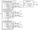
- FIG. 3is a block diagram illustrating a communication system, according to an embodiment.
- Communication system 300comprises a plurality of electronic devices 302 a , 302 b - 302 n (collectively electronic devices 302 a - 302 n ), where n represents an arbitrary number of devices (e.g. data storage devices such as hard disk drives (HDDs) and/or solid-state drives (SSDs) in a datacenter 301 ) that may vary from implementation to implementation.
- the type of device represented by one or more of the electronic devices 302 a - 302 nmay include, for example and according to an embodiment, a data storage device, a server device, a network switch, and a power distribution unit.
- Each device 302 a - 302 ncomprises and is at least in part under the control of one or more controller 304 circuitry (e.g., an application specific integrated circuit, or ASIC) comprising and/or embodying one or more sequences of instructions (i.e., logic) which when executed by one or more processors are enabled to carry out corresponding steps, operations, routines, procedures, and the like.
- controller 304 circuitrye.g., an application specific integrated circuit, or ASIC
- ASICapplication specific integrated circuit
- each device 302 a - 302 nfurther comprises a visible LED 307 , such as a Power ON LED configured to emit a corresponding visible steady-state signal 311 a - 311 n , and an infrared (IR) light-emitting diode (LED) 306 configured to externally transmit (i.e., to outside of the device) and communicate identifying information, from the source or manufacturer of the device, that particularly identifies the device (see, e.g., data bytes 206 of FIG. 2 ), such as via a corresponding infrared carrier wave signal 310 a - 310 n carrying a payload comprising such respective identifying information.
- IRinfrared
- Infrared radiationas commonly known is generally invisible (to the human eye) radiation or light with frequencies lying between visible light and microwave (e.g., generally understood as, at wavelengths between around 700 nanometers to 1 millimeter).
- Each of the visible LED 307 and the IR LED 306may be implemented to operate under the control of separate controller 304 logic routines.
- the routine associated with the visible LED 307may operationally control the LED 307 in a static or steady state (e.g., light on means device power is on, light off means device power is off), and the routine associated with the IR LED 306 may operationally control the IR LED 308 according to a repeating loop as depicted in FIG. 2 , so that any dynamic information (see, e.g., firmware version 206 d and health 206 e of FIG. 2 ) being communicated by IR LED 306 can be updated and transmitted accordingly.
- each of the visible LED 307 and the IR LED 306may be implemented closely positioned to each other, e.g., adjacent, on the same circuit board.
- each device 302 a - 302 nmay further comprise a light pipe 308 optically coupled to the visible LED 307 for transmission of the corresponding visible light signal 311 a - 311 n from the LED 307 to outside of each respective device 302 a - 302 n , and where the IR LED 306 is further optically coupled to the same light pipe 308 for transmission of the corresponding encoded data bytes 206 payload ( FIG.
- the visible LED 307 and the IR LED 306 outputsmay be merged to one common light pipe 308 to transmit both to the exterior of the respective device 302 a - 302 n , as the different frequencies of light allow both outputs to travel through one shared channel.
- a system vendormay decide to use a light pipe to assist in transmitting the information to outside of or to the perimeter of the system.
- a system vendormay decide to use a light pipe to assist in transmitting the information to outside of or to the perimeter of the system.
- SSDsenterprise solid-state drives
- U.2 or U.3 interface standardswhich define the pins/signals for visible LED communication
- SSD suppliersmay want or need to place the IR LED 306 and the visible LED 307 at or on a certain position within the device to facilitate connection with such an external system light pipe.
- communication system 300further comprises a portable IR reader 312 comprising a light funnel 316 configured to avoid interference from neighboring devices installed in the same system.
- a single IR reader 312 unitmay be employed to systematically scan a row or shelf or rack of electronic devices to “read” the respective communication signals 310 a - 310 n transmitted from each of the respective devices 302 a - 302 n .
- the light funnel 316leads to a recessed IR sensor 317 , collectively configured with the light funnel 316 to narrow the receiving field of the sensor, i.e., the sensor field.
- the IR reader 312is configured to receive the signals 310 a - 310 n via the light funnel 316 and recessed IR sensor 317 and, according to an embodiment, further configured to decode the signals 310 a - 310 n via an on-board decoder 313 or processor, for display on an on-board display 314 .
- the IR reader 312is considered a handheld device.
- the IR reader 312may alternatively be configured to be a “dumb” device lacking the decoder 313 and/or display 314 , whereby the IR reader 312 is configured to pass through each sensed IR signal 310 a - 310 n received from a corresponding device 302 a - 302 n to an external processing device, for example, to a USB (Universal Serial Bus)-connected device, such as a laptop computer, via a USB communication link 318 and/or to a smart phone (on which a suitable application or “app” is installed) or tablet or the like via a suitable communication link depicted as phone communication link 319 .
- USBUniversal Serial Bus
- FIG. 1Ais a block diagram illustrating an example operating context of such an electronic device with which embodiments of the invention may be implemented.
- FIG. 1Aillustrates a generic SSD architecture 150 , with an SSD 152 communicatively coupled with a host 154 through a primary communication interface 156 .
- Embodimentsare not limited to a configuration as depicted in FIG. 1A , rather, embodiments may be implemented with SSD configurations other than that illustrated in FIG. 1A .
- embodimentsmay be implemented to operate in other environments that rely on non-volatile memory storage components for writing and reading of data.
- Host 154broadly represents any type of computing hardware, software, or firmware (or any combination of the foregoing) that makes, among others, data I/O requests or calls to one or more memory device.
- host 154may be an operating system executing on a computer, a tablet, a mobile phone, or generally any type of computing device that contains or interacts with storage memory.
- the primary interface 156 coupling host 154 to SSD 152may be, for example, a storage system's internal bus or a communication cable or a wireless communication link, or the like.
- the example SSD 152 illustrated in FIG. 1Aincludes an interface 160 , a controller 162 (e.g., a controller having firmware logic therein), an addressing 164 function block, data buffer cache 166 , and one or more non-volatile memory (NVM) components 170 a , 170 b - 170 n , where n represents an arbitrary number of NVM components that may vary from implementation to implementation.
- a controller 162e.g., a controller having firmware logic therein
- NVMnon-volatile memory
- Interface 160is a point of interaction between components, namely SSD 152 and host 154 in this context, and is applicable at the level of both hardware and software. This allows a component to communicate with other components via an input/output (IO) system and an associated protocol.
- IOinput/output
- a hardware interfaceis typically described by the mechanical, electrical and logical signals at the interface and the protocol for sequencing them.
- SCSISerial Computer System Interface
- SASSerial Attached SCSI
- SATASerial ATA
- An SSD 152includes a controller 162 , which incorporates the electronics that bridge the non-volatile memory components (e.g., NAND flash) to the host, such as non-volatile memory 170 a , 170 b - 170 n to host 154 .
- the controlleris typically an embedded processor that executes firmware-level code and can be a significant factor in SSD performance.
- Controller 162interfaces with non-volatile memory 170 a , 170 b - 170 n via an addressing 164 function block.
- the addressing 164 functionoperates, for example, to manage mappings between logical block addresses (LBAs) from the host 154 to a corresponding physical block address on the SSD 152 , namely, on the non-volatile memory 170 a , 170 b - 170 n of SSD 152 . Because the non-volatile memory page and the host sectors are different sizes, an SSD has to build and maintain a data structure that enables it to translate between the host writing data to or reading data from a sector, and the physical non-volatile memory page on which that data is actually placed.
- LBAslogical block addresses
- This table structure or “mapping”may be built and maintained for a session in the SSD's volatile memory 172 , such as DRAM or some other local volatile memory component accessible to controller 162 and addressing 164 .
- the table structuremay be maintained more persistently across sessions in the SSD's non-volatile memory such as non-volatile memory 170 a , 170 b - 170 n.
- Data buffer cache 166 of an SSD 152typically uses DRAM as a cache, similar to the cache in hard disk drives.
- Data buffer cache 166serves as a buffer or staging area for the transmission of data to and from the non-volatile memory components, as well as serves as a cache for speeding up future requests for the cached data.
- Data buffer cache 166is typically implemented with volatile memory so the data stored therein is not permanently stored in the cache, i.e., the data is not persistent.
- SSD 152includes the one or more non-volatile memory 170 a , 170 b - 170 n components.
- the non-volatile memory components 170 a , 170 b - 170 nmay be implemented as flash memory (e.g., NAND or NOR flash), or other types of solid-state memory available now or in the future.
- the non-volatile memory 170 a , 170 b - 170 n componentsare the actual memory electronic components on which data is persistently stored.
- the non-volatile memory 170 a , 170 b - 170 n components of SSD 152can be considered the analogue to the hard disks in hard-disk drive (HDD) storage devices.
- HDDhard-disk drive
- references herein to a data storage devicemay encompass a multi-medium storage device (or “multi-medium device”, which may at times be referred to as a “multi-tier device” or “hybrid drive”).
- a multi-medium storage devicerefers generally to a storage device having functionality of both a traditional HDD (see, e.g., HDD 100 ) combined with an SSD (see, e.g., SSD 150 ) using non-volatile memory, such as flash or other solid-state (e.g., integrated circuits) memory, which is electrically erasable and programmable.
- the solid-state portion of a hybrid drivemay include its own corresponding controller functionality, which may be integrated into a single controller along with the HDD functionality.
- a multi-medium storage devicemay be architected and configured to operate and to utilize the solid-state portion in a number of ways, such as, for non-limiting examples, by using the solid-state memory as cache memory, for storing frequently-accessed data, for storing I/O intensive data, for storing metadata corresponding to payload data (e.g., for assisting with decoding the payload data), and the like.
- a multi-medium storage devicemay be architected and configured essentially as two storage devices in a single enclosure, i.e., a traditional HDD and an SSD, with either one or multiple interfaces for host connection.
- Embodimentsmay also be used in the context of hard disk drives (HDDs), such as external HDDs in which cases/enclosures are used to enclose or house an HDD, and with which IR LEDs as illustrated and described herein may be implemented.
- HDDshard disk drives
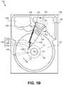
- FIG. 1Ba plan view illustrating an HDD 100 is shown in FIG. 1B to illustrate exemplary operating components of such an electronic device with which embodiments of the invention may be implemented.
- FIG. 1Billustrates the functional arrangement of components of the HDD 100 including a slider 110 b that includes a magnetic read-write head 110 a .
- slider 110 b and head 110 amay be referred to as a head slider.
- the HDD 100includes at least one head gimbal assembly (HGA) 110 including the head slider, a lead suspension 110 c attached to the head slider typically via a flexure, and a load beam 110 d attached to the lead suspension 110 c .
- the HDD 100also includes at least one recording medium 120 rotatably mounted on a spindle 124 and a drive motor (not visible) attached to the spindle 124 for rotating the medium 120 .
- HGAhead gimbal assembly
- the read-write head 110 awhich may also be referred to as a transducer, includes a write element and a read element for respectively writing and reading information stored on the medium 120 of the HDD 100 .
- the medium 120 or a plurality of disk mediamay be affixed to the spindle 124 with a disk clamp 128 .
- the HDD 100further includes an arm 132 attached to the HGA 110 , a carriage 134 , a voice coil motor (VCM) that includes an armature 136 including a voice coil 140 attached to the carriage 134 and a stator 144 including a voice-coil magnet (not visible).
- the armature 136 of the VCMis attached to the carriage 134 and is configured to move the arm 132 and the HGA 110 to access portions of the medium 120 , all collectively mounted on a pivot shaft 148 with an interposed pivot bearing assembly 152 .
- the carriage 134may be referred to as an “E-block,” or comb, because the carriage is arranged to carry a ganged array of arms that gives it the appearance of a comb.
- An assemblycomprising a head gimbal assembly (e.g., HGA 110 ) including a flexure to which the head slider is coupled, an actuator arm (e.g., arm 132 ) and/or load beam to which the flexure is coupled, and an actuator (e.g., the VCM) to which the actuator arm is coupled, may be collectively referred to as a head stack assembly (HSA).
- HSAhead stack assembly
- An HSAmay, however, include more or fewer components than those described.
- an HSAmay refer to an assembly that further includes electrical interconnection components.
- an HSAis the assembly configured to move the head slider to access portions of the medium 120 for read and write operations.
- electrical signalscomprising a write signal to and a read signal from the head 110 a
- FCAflexible cable assembly
- FCAflexible cable assembly
- Interconnection between the flex cable 156 and the head 110 amay include an arm-electronics (AE) module 160 , which may have an on-board pre-amplifier for the read signal, as well as other read-channel and write-channel electronic components.
- the AE module 160may be attached to the carriage 134 as shown.
- the flex cable 156may be coupled to an electrical-connector block 164 , which provides electrical communication, in some configurations, through an electrical feed-through provided by an HDD housing 168 .
- the HDD housing 168(or “enclosure base” or “baseplate” or simply “base”), in conjunction with an HDD cover, provides a semi-sealed (or hermetically sealed, in some configurations) protective enclosure for the information storage components of the HDD 100 .
- DSPdigital-signal processor
- the spinning medium 120creates a cushion of air that acts as an air-bearing on which the air-bearing surface (ABS) of the slider 110 b rides so that the slider 110 b flies above the surface of the medium 120 without making contact with a thin magnetic-recording layer in which information is recorded.
- ABSair-bearing surface
- the spinning medium 120creates a cushion of gas that acts as a gas or fluid bearing on which the slider 110 b rides.
- the electrical signal provided to the voice coil 140 of the VCMenables the head 110 a of the HGA 110 to access a track 176 on which information is recorded.
- the armature 136 of the VCMswings through an arc 180 , which enables the head 110 a of the HGA 110 to access various tracks on the medium 120 .
- Informationis stored on the medium 120 in a plurality of radially nested tracks arranged in sectors on the medium 120 , such as sector 184 .
- each trackis composed of a plurality of sectored track portions (or “track sector”) such as sectored track portion 188 .
- Each sectored track portion 188may include recorded information, and a header containing error correction code information and a servo-burst-signal pattern, such as an ABCD-servo-burst-signal pattern, which is information that identifies the track 176 .
- a servo-burst-signal patternsuch as an ABCD-servo-burst-signal pattern, which is information that identifies the track 176 .
- the read element of the head 110 a of the HGA 110reads the servo-burst-signal pattern, which provides a position-error-signal (PES) to the servo electronics, which controls the electrical signal provided to the voice coil 140 of the VCM, thereby enabling the head 110 a to follow the track 176 .
- PESposition-error-signal
- the head 110 aUpon finding the track 176 and identifying a particular sectored track portion 188 , the head 110 a either reads information from the track 176 or writes information to the track 176 depending on instructions received by the disk controller from an external agent, for example, a microprocessor of a computer system.
- an external agentfor example, a microprocessor of a computer system.
- An HDD's electronic architecturecomprises numerous electronic components for performing their respective functions for operation of an HDD, such as a hard disk controller (“HDC”), an interface controller, an arm electronics module, a data channel, a motor driver, a servo processor, buffer memory, etc. Two or more of such components may be combined on a single integrated circuit board referred to as a “system on a chip” (“SOC”). Several, if not all, of such electronic components are typically arranged on a printed circuit board that is coupled to the bottom side of an HDD, such as to HDD housing 168 .
- HDChard disk controller
- SOCsystem on a chip
- references herein to a hard disk drivemay encompass an information storage device that is at times referred to as a “hybrid drive”.
- a hybrid driverefers generally to a storage device having functionality of both a traditional HDD (see, e.g., HDD 100 ) combined with solid-state storage device (SSD) using non-volatile memory, such as flash or other solid-state (e.g., integrated circuits) memory, which is electrically erasable and programmable.
- the solid-state portion of a hybrid drivemay include its own corresponding controller functionality, which may be integrated into a single controller along with the HDD functionality.
- a hybrid drivemay be architected and configured to operate and to utilize the solid-state portion in a number of ways, such as, for non-limiting examples, by using the solid-state memory as cache memory, for storing frequently-accessed data, for storing I/O intensive data, and the like. Further, a hybrid drive may be architected and configured essentially as two storage devices in a single enclosure, i.e., a traditional HDD and an SSD, with either one or multiple interfaces for host connection.
Landscapes
- Engineering & Computer Science (AREA)
- Physics & Mathematics (AREA)
- Electromagnetism (AREA)
- Computer Networks & Wireless Communication (AREA)
- Signal Processing (AREA)
- Theoretical Computer Science (AREA)
- Quality & Reliability (AREA)
- General Engineering & Computer Science (AREA)
- General Physics & Mathematics (AREA)
- Computing Systems (AREA)
- Debugging And Monitoring (AREA)
- Signal Processing For Digital Recording And Reproducing (AREA)
- Optical Communication System (AREA)
Abstract
Description
Claims (20)
Priority Applications (4)
| Application Number | Priority Date | Filing Date | Title |
|---|---|---|---|
| US17/173,017US11455225B2 (en) | 2020-08-04 | 2021-02-10 | Electronic device having infrared light-emitting diode for data transmission |
| DE112021000148.5TDE112021000148T5 (en) | 2020-08-04 | 2021-06-15 | ELECTRONIC DEVICE WITH INFRARED LED FOR DATA TRANSMISSION |
| CN202180006662.8ACN114731202B (en) | 2020-08-04 | 2021-06-15 | Electronic device with infrared light emitting diode for data transmission |
| PCT/US2021/037516WO2022031373A1 (en) | 2020-08-04 | 2021-06-15 | Electronic device having infrared light-emitting diode for data transmission |
Applications Claiming Priority (2)
| Application Number | Priority Date | Filing Date | Title |
|---|---|---|---|
| US202063060959P | 2020-08-04 | 2020-08-04 | |
| US17/173,017US11455225B2 (en) | 2020-08-04 | 2021-02-10 | Electronic device having infrared light-emitting diode for data transmission |
Publications (2)
| Publication Number | Publication Date |
|---|---|
| US20220043729A1 US20220043729A1 (en) | 2022-02-10 |
| US11455225B2true US11455225B2 (en) | 2022-09-27 |
Family
ID=80115045
Family Applications (1)
| Application Number | Title | Priority Date | Filing Date |
|---|---|---|---|
| US17/173,017ActiveUS11455225B2 (en) | 2020-08-04 | 2021-02-10 | Electronic device having infrared light-emitting diode for data transmission |
Country Status (4)
| Country | Link |
|---|---|
| US (1) | US11455225B2 (en) |
| CN (1) | CN114731202B (en) |
| DE (1) | DE112021000148T5 (en) |
| WO (1) | WO2022031373A1 (en) |
Cited By (1)
| Publication number | Priority date | Publication date | Assignee | Title |
|---|---|---|---|---|
| US20220149943A1 (en)* | 2019-03-26 | 2022-05-12 | Nec Corporation | Light transmission device, and control method of same |
Citations (44)
| Publication number | Priority date | Publication date | Assignee | Title |
|---|---|---|---|---|
| GB2185134A (en)* | 1985-11-20 | 1987-07-08 | Tokyo Keiki Kk | Memory package |
| US4829166A (en)* | 1986-12-01 | 1989-05-09 | Froelich Ronald W | Computerized data-bearing card and reader/writer therefor |
| US5196682A (en)* | 1986-06-30 | 1993-03-23 | Wang Laboratories, Inc. | Infrared optical card having an opaque case for hiding internal components |
| US5218466A (en)* | 1991-06-03 | 1993-06-08 | Motorola, Inc. | Communication device with optical communication interface |
| US5247380A (en) | 1988-01-27 | 1993-09-21 | Spectrix Corp | Infrared communications network |
| US5343319A (en)* | 1993-06-14 | 1994-08-30 | Motorola, Inc. | Apparatus for adapting an electrical communications port to an optical communications port |
| US5600471A (en)* | 1994-04-28 | 1997-02-04 | Victor Company Of Japan, Ltd. | Optical wireless data transmission system and optical wireless data transmitting/receiving apparatus |
| US5602668A (en)* | 1994-11-30 | 1997-02-11 | International Business Machines Corporation | Data communications and illuminated light on the same optical fiber |
| US5633742A (en)* | 1994-09-21 | 1997-05-27 | Fisher Berkeley Corporation | Optical data communication and location apparatus, system and method and transmitters and receivers for use therewith |
| US5726786A (en)* | 1995-11-21 | 1998-03-10 | The Aerospace Corporation | Free-space star-coupled optical data bus |
| US5774637A (en)* | 1993-11-12 | 1998-06-30 | Iti Innovative Technology Ltd. | Cordless printer control device |
| US5838472A (en)* | 1996-07-03 | 1998-11-17 | Spectrix Corporation | Method and apparatus for locating a transmitter of a diffuse infrared signal within an enclosed area |
| US5850189A (en)* | 1995-05-16 | 1998-12-15 | International Business Machines Corporation | Apparatus and method for infrared communication |
| US5861969A (en)* | 1996-03-05 | 1999-01-19 | Alps Electric Co., Ltd. | Infrared signal transmitting apparatus |
| US6128117A (en)* | 1997-04-15 | 2000-10-03 | Samsung Electronics Co., Ltd. | Computer system provided with infrared communication cable |
| US6211797B1 (en)* | 1997-07-29 | 2001-04-03 | Sharp Kabushiki Kaisha | Infrared communication control apparatus and method |
| US6256129B1 (en)* | 1997-03-28 | 2001-07-03 | Samsung Electronics Co., Ltd. | Portable computer and method of automatically controlling direction of infrared signal transmission and reception |
| US6298047B1 (en)* | 1998-05-20 | 2001-10-02 | Steelcase Development Inc. | Method and apparatus for establishing a data link between a portable data communications device and an interface circuit |
| US6337856B1 (en)* | 1998-05-20 | 2002-01-08 | Steelcase Development Corporation | Multimedia data communications system |
| US20020129186A1 (en) | 1999-04-30 | 2002-09-12 | Compaq Information Technologies Group, L.P. | Replacement, upgrade and/or addition of hot-pluggable components in a computer system |
| US6480313B1 (en)* | 1997-01-27 | 2002-11-12 | Kabushiki Kaisha Toshiba | Apparatus and method of repeating for infrared communication devices |
| US6693879B1 (en)* | 1999-02-22 | 2004-02-17 | Kabushiki Kaisha Toshiba | Data communication apparatus and method |
| US20040071471A1 (en)* | 2002-10-10 | 2004-04-15 | Interlink Electronics, Inc. | Method and system for pairing a remote control transmitter and receiver |
| US20040094696A1 (en)* | 2000-09-05 | 2004-05-20 | Roberto Ramirez-Iniguez | Wireless communication receiver using a totally internally reflecting concentrator |
| US20040161246A1 (en)* | 2001-10-23 | 2004-08-19 | Nobuyuki Matsushita | Data communication system, data transmitter and data receiver |
| US20040203317A1 (en) | 2003-04-08 | 2004-10-14 | David Small | Wireless interactive doll-houses and playsets therefor |
| US20050258232A1 (en)* | 2001-02-01 | 2005-11-24 | Yuji Kitamura | Method and system for tracking items using a distributed infrastructure |
| US7058308B2 (en)* | 2001-07-31 | 2006-06-06 | Inventec Appliances Corp. | Method for communicating multimedia data between electronic devices by means of IR ray |
| US20070092257A1 (en)* | 2005-10-21 | 2007-04-26 | Smith Dale T | Optical interface for communicating optical transceiver status information |
| US20080052698A1 (en)* | 2006-08-25 | 2008-02-28 | Microsoft Corporation | Providing firmware updates to portable media devices |
| US7630645B2 (en)* | 2005-11-14 | 2009-12-08 | Sigmatel, Inc. | Detecting an infrared transceiver type |
| US20120025949A1 (en)* | 2010-07-29 | 2012-02-02 | Reed Matthew H | Concurrent Infrared Signal, Single Thread Low Power Protocol and System for Pet Control |
| US8135282B2 (en)* | 2008-07-31 | 2012-03-13 | Finisar Corporation | Fiberoptic transceiver module with integral status indicators |
| WO2012044159A2 (en) | 2010-10-01 | 2012-04-05 | Vanderlande Industries B.V. | Device for sorting products |
| EP2675084A1 (en) | 2012-06-15 | 2013-12-18 | Outstanding Technology Co., Ltd. | Content supplying system which uses spatial light |
| US8947816B1 (en)* | 2013-05-01 | 2015-02-03 | Western Digital Technologies, Inc. | Data storage assembly for archive cold storage |
| US20150125154A1 (en) | 2013-11-04 | 2015-05-07 | Samsung Electronics Co., Ltd. | Ir communication method and electronic device thereof |
| US20160196194A1 (en)* | 2014-12-17 | 2016-07-07 | Quanta Computer Inc. | Automatic hardware recovery system |
| US9622030B1 (en) | 2007-01-20 | 2017-04-11 | Centrak, Inc. | Methods and systems for synchronized ultrasonic real time location |
| WO2017093559A1 (en) | 2015-12-03 | 2017-06-08 | Robert Bosch Gmbh | Intelligent lighting and sensing system and method thereof |
| US20180138975A1 (en)* | 2016-11-16 | 2018-05-17 | Adobe Systems Incorporated | Location tracking using short-range infrared transmission |
| US20190310958A1 (en)* | 2018-03-02 | 2019-10-10 | Samsung Electronics Co., Ltd. | Mechanism to identify fpga and ssd pairing in a multi-device environment |
| US20200267221A1 (en)* | 2017-08-24 | 2020-08-20 | Alibaba Group Holding Limited | Method, system, and device for controlling an internet of things device |
| US20220114884A1 (en)* | 2011-09-13 | 2022-04-14 | Lutron Technology Company, LLC | Visible Light Communication System And Method |
Family Cites Families (11)
| Publication number | Priority date | Publication date | Assignee | Title |
|---|---|---|---|---|
| JP2005267497A (en)* | 2004-03-22 | 2005-09-29 | Hitachi Global Storage Technologies Netherlands Bv | Data storage device, control method thereof, and magnetic disk storage device |
| US8009192B2 (en)* | 2006-05-17 | 2011-08-30 | Mitsubishi Electric Research Laboratories, Inc. | System and method for sensing geometric and photometric attributes of a scene with multiplexed illumination and solid states optical devices |
| US9440144B2 (en)* | 2011-04-21 | 2016-09-13 | Sony Interactive Entertainment Inc. | User identified to a controller |
| US8547036B2 (en)* | 2011-11-20 | 2013-10-01 | Available For Licensing | Solid state light system with broadband optical communication capability |
| US9917644B2 (en)* | 2012-10-09 | 2018-03-13 | Booz Allen Hamilton Inc. | Method and system for data transmission and communication using imperceptible differences in visible light |
| US10353631B2 (en)* | 2013-07-23 | 2019-07-16 | Intel Corporation | Techniques for moving data between a network input/output device and a storage device |
| US11133866B2 (en)* | 2014-02-25 | 2021-09-28 | Pharmaseq, Inc. | All optical identification and sensor system with power on discovery |
| US9584965B2 (en)* | 2014-07-25 | 2017-02-28 | General Electric Company | Methods and apparatus to facilitate proximity detection and location tracking |
| ES2870629T3 (en)* | 2014-10-02 | 2021-10-27 | Ecoatm Llc | App for device evaluation and other processes associated with device recycling |
| JP6800858B2 (en)* | 2015-02-10 | 2020-12-16 | ブライトコーデス テクノロジーズ リミテッド | Systems and methods for providing optically encoded information |
| US10257050B2 (en)* | 2015-08-28 | 2019-04-09 | Ca, Inc. | Data center cable identification |
- 2021
- 2021-02-10USUS17/173,017patent/US11455225B2/enactiveActive
- 2021-06-15CNCN202180006662.8Apatent/CN114731202B/enactiveActive
- 2021-06-15DEDE112021000148.5Tpatent/DE112021000148T5/enactivePending
- 2021-06-15WOPCT/US2021/037516patent/WO2022031373A1/ennot_activeCeased
Patent Citations (44)
| Publication number | Priority date | Publication date | Assignee | Title |
|---|---|---|---|---|
| GB2185134A (en)* | 1985-11-20 | 1987-07-08 | Tokyo Keiki Kk | Memory package |
| US5196682A (en)* | 1986-06-30 | 1993-03-23 | Wang Laboratories, Inc. | Infrared optical card having an opaque case for hiding internal components |
| US4829166A (en)* | 1986-12-01 | 1989-05-09 | Froelich Ronald W | Computerized data-bearing card and reader/writer therefor |
| US5247380A (en) | 1988-01-27 | 1993-09-21 | Spectrix Corp | Infrared communications network |
| US5218466A (en)* | 1991-06-03 | 1993-06-08 | Motorola, Inc. | Communication device with optical communication interface |
| US5343319A (en)* | 1993-06-14 | 1994-08-30 | Motorola, Inc. | Apparatus for adapting an electrical communications port to an optical communications port |
| US5774637A (en)* | 1993-11-12 | 1998-06-30 | Iti Innovative Technology Ltd. | Cordless printer control device |
| US5600471A (en)* | 1994-04-28 | 1997-02-04 | Victor Company Of Japan, Ltd. | Optical wireless data transmission system and optical wireless data transmitting/receiving apparatus |
| US5633742A (en)* | 1994-09-21 | 1997-05-27 | Fisher Berkeley Corporation | Optical data communication and location apparatus, system and method and transmitters and receivers for use therewith |
| US5602668A (en)* | 1994-11-30 | 1997-02-11 | International Business Machines Corporation | Data communications and illuminated light on the same optical fiber |
| US5850189A (en)* | 1995-05-16 | 1998-12-15 | International Business Machines Corporation | Apparatus and method for infrared communication |
| US5726786A (en)* | 1995-11-21 | 1998-03-10 | The Aerospace Corporation | Free-space star-coupled optical data bus |
| US5861969A (en)* | 1996-03-05 | 1999-01-19 | Alps Electric Co., Ltd. | Infrared signal transmitting apparatus |
| US5838472A (en)* | 1996-07-03 | 1998-11-17 | Spectrix Corporation | Method and apparatus for locating a transmitter of a diffuse infrared signal within an enclosed area |
| US6480313B1 (en)* | 1997-01-27 | 2002-11-12 | Kabushiki Kaisha Toshiba | Apparatus and method of repeating for infrared communication devices |
| US6256129B1 (en)* | 1997-03-28 | 2001-07-03 | Samsung Electronics Co., Ltd. | Portable computer and method of automatically controlling direction of infrared signal transmission and reception |
| US6128117A (en)* | 1997-04-15 | 2000-10-03 | Samsung Electronics Co., Ltd. | Computer system provided with infrared communication cable |
| US6211797B1 (en)* | 1997-07-29 | 2001-04-03 | Sharp Kabushiki Kaisha | Infrared communication control apparatus and method |
| US6298047B1 (en)* | 1998-05-20 | 2001-10-02 | Steelcase Development Inc. | Method and apparatus for establishing a data link between a portable data communications device and an interface circuit |
| US6337856B1 (en)* | 1998-05-20 | 2002-01-08 | Steelcase Development Corporation | Multimedia data communications system |
| US6693879B1 (en)* | 1999-02-22 | 2004-02-17 | Kabushiki Kaisha Toshiba | Data communication apparatus and method |
| US20020129186A1 (en) | 1999-04-30 | 2002-09-12 | Compaq Information Technologies Group, L.P. | Replacement, upgrade and/or addition of hot-pluggable components in a computer system |
| US20040094696A1 (en)* | 2000-09-05 | 2004-05-20 | Roberto Ramirez-Iniguez | Wireless communication receiver using a totally internally reflecting concentrator |
| US20050258232A1 (en)* | 2001-02-01 | 2005-11-24 | Yuji Kitamura | Method and system for tracking items using a distributed infrastructure |
| US7058308B2 (en)* | 2001-07-31 | 2006-06-06 | Inventec Appliances Corp. | Method for communicating multimedia data between electronic devices by means of IR ray |
| US20040161246A1 (en)* | 2001-10-23 | 2004-08-19 | Nobuyuki Matsushita | Data communication system, data transmitter and data receiver |
| US20040071471A1 (en)* | 2002-10-10 | 2004-04-15 | Interlink Electronics, Inc. | Method and system for pairing a remote control transmitter and receiver |
| US20040203317A1 (en) | 2003-04-08 | 2004-10-14 | David Small | Wireless interactive doll-houses and playsets therefor |
| US20070092257A1 (en)* | 2005-10-21 | 2007-04-26 | Smith Dale T | Optical interface for communicating optical transceiver status information |
| US7630645B2 (en)* | 2005-11-14 | 2009-12-08 | Sigmatel, Inc. | Detecting an infrared transceiver type |
| US20080052698A1 (en)* | 2006-08-25 | 2008-02-28 | Microsoft Corporation | Providing firmware updates to portable media devices |
| US9622030B1 (en) | 2007-01-20 | 2017-04-11 | Centrak, Inc. | Methods and systems for synchronized ultrasonic real time location |
| US8135282B2 (en)* | 2008-07-31 | 2012-03-13 | Finisar Corporation | Fiberoptic transceiver module with integral status indicators |
| US20120025949A1 (en)* | 2010-07-29 | 2012-02-02 | Reed Matthew H | Concurrent Infrared Signal, Single Thread Low Power Protocol and System for Pet Control |
| WO2012044159A2 (en) | 2010-10-01 | 2012-04-05 | Vanderlande Industries B.V. | Device for sorting products |
| US20220114884A1 (en)* | 2011-09-13 | 2022-04-14 | Lutron Technology Company, LLC | Visible Light Communication System And Method |
| EP2675084A1 (en) | 2012-06-15 | 2013-12-18 | Outstanding Technology Co., Ltd. | Content supplying system which uses spatial light |
| US8947816B1 (en)* | 2013-05-01 | 2015-02-03 | Western Digital Technologies, Inc. | Data storage assembly for archive cold storage |
| US20150125154A1 (en) | 2013-11-04 | 2015-05-07 | Samsung Electronics Co., Ltd. | Ir communication method and electronic device thereof |
| US20160196194A1 (en)* | 2014-12-17 | 2016-07-07 | Quanta Computer Inc. | Automatic hardware recovery system |
| WO2017093559A1 (en) | 2015-12-03 | 2017-06-08 | Robert Bosch Gmbh | Intelligent lighting and sensing system and method thereof |
| US20180138975A1 (en)* | 2016-11-16 | 2018-05-17 | Adobe Systems Incorporated | Location tracking using short-range infrared transmission |
| US20200267221A1 (en)* | 2017-08-24 | 2020-08-20 | Alibaba Group Holding Limited | Method, system, and device for controlling an internet of things device |
| US20190310958A1 (en)* | 2018-03-02 | 2019-10-10 | Samsung Electronics Co., Ltd. | Mechanism to identify fpga and ssd pairing in a multi-device environment |
Non-Patent Citations (6)
| Title |
|---|
| Atmel, AVR415: RC5 IR Remote Control Transmitter on tiny AVR and megaAVR, 2016 (Year: 2016).* |
| Dell, Dell Enterprise HDD: What is the meaning of LED on Physical Drives (PD)?, dell.com/support, Article ID SLN305722, Last Modified Sep. 14, 2019, 2 pages, downloaded from https://www.dell.com/support/article/en-in/sln305722/dell-enterprise-hdd-what-is-the-meaning-of-led-on-physical-drives-pd?lang=en. |
| Korean Intellectual Property Office (ISA/KR), PCT International Search Report and Written Opinion for counterpart International application No. PCT/US2021/037516, dated Nov. 2, 2021, 10 pages. |
| Mohammed Zafar Faraz et al., LI-FI Based Data Storage Device, International Journal of Computer Science Trends and Technology (IJCST), Jul.-Aug. 2016, vol. 4 Issue 4, pp. 261-265, www.ijcstjournal.org. |
| Netapp, Identify disks by turning on their LEDs, ONTAP 9 Documentation Center, 1 page, downloaded on May 4, 2020 from https://docs.netapp.com/ontap-9/index.jsp?topic=%2Fcom.netapp.doc.dot-cm-cmpr-960%2Fstorage_disk_set-led.html. |
| Suse, 12 Storage Enclosure LED Utilities for MD Software RAIDs, SUSE Linux Enterprise Server Documentation, 8 pages, downloaded on May 4, 2020 from https://documentation.suse.com/sles/15-SP1/html/SLES-all/cha-raid-leds.html. |
Cited By (3)
| Publication number | Priority date | Publication date | Assignee | Title |
|---|---|---|---|---|
| US20220149943A1 (en)* | 2019-03-26 | 2022-05-12 | Nec Corporation | Light transmission device, and control method of same |
| US11671176B2 (en)* | 2019-03-26 | 2023-06-06 | Nec Corporation | Light transmission device, and control method of same |
| US12199674B2 (en)* | 2019-03-26 | 2025-01-14 | Nec Corporation | Light transmission device, and control method of same |
Also Published As
| Publication number | Publication date |
|---|---|
| CN114731202B (en) | 2024-03-22 |
| WO2022031373A1 (en) | 2022-02-10 |
| US20220043729A1 (en) | 2022-02-10 |
| DE112021000148T5 (en) | 2022-07-21 |
| CN114731202A (en) | 2022-07-08 |
Similar Documents
| Publication | Publication Date | Title |
|---|---|---|
| US9552174B2 (en) | Method and system for preventing unreliable data operations at cold temperatures | |
| US9373354B2 (en) | Method and system for preventing unreliable data operations at cold temperatures | |
| CN108533531B (en) | Fan noise attenuation at hard disk drives in rack mount | |
| US9704521B1 (en) | Actuator limiters for multiple disk-stack, shared actuator hard disk drive | |
| US9552835B1 (en) | Actuator limiters for multiple disk-stack, shared actuator hard disk drive | |
| US10332555B1 (en) | Reducing vibration transmission in a dual actuator disk drive utilizing a single pivot shaft | |
| US11456009B1 (en) | Shared disk configuration in a multiple actuator hard disk drive | |
| US10897273B2 (en) | System-level error correction coding allocation based on device population data integrity sharing | |
| US20160358621A1 (en) | Self-Servo Write Non-Reference Head Position Measuring | |
| US11881232B2 (en) | Dual spindle motor hard disk drive | |
| US11954027B2 (en) | Parasitic commands for equalizing logical unit capacity in asymmetric multiple actuator hard disk drive | |
| US11455225B2 (en) | Electronic device having infrared light-emitting diode for data transmission | |
| US8736993B2 (en) | Failure-resistant multi-LUN hard disk drive | |
| US11430474B1 (en) | Hard disk drive suspension tail having narrowing tip | |
| US12406102B2 (en) | Detection of data storage device removal | |
| US20250259656A1 (en) | Low-power low-noise data storage array cooling | |
| US12111705B2 (en) | Dynamically controlling variable data storage device threshold temperatures within a storage system | |
| US12046257B1 (en) | Reducing peak power consumption in a multi-actuator hard disk drive | |
| US11482253B1 (en) | Per head, per profile finalize to move repeatable runout compensation values to NAND memory | |
| US7663826B2 (en) | Method and apparatus for copying data from one disc drive to another disc drive |
Legal Events
| Date | Code | Title | Description |
|---|---|---|---|
| AS | Assignment | Owner name:WESTERN DIGITAL TECHNOLOGIES, INC., CALIFORNIA Free format text:ASSIGNMENT OF ASSIGNORS INTEREST;ASSIGNORS:FURLONG, JEFF;JENKINS, DEAN M.;REEL/FRAME:055278/0834 Effective date:20200804 | |
| FEPP | Fee payment procedure | Free format text:ENTITY STATUS SET TO UNDISCOUNTED (ORIGINAL EVENT CODE: BIG.); ENTITY STATUS OF PATENT OWNER: LARGE ENTITY | |
| AS | Assignment | Owner name:JPMORGAN CHASE BANK, N.A., AS AGENT, ILLINOIS Free format text:SECURITY INTEREST;ASSIGNOR:WESTERN DIGITAL TECHNOLOGIES, INC.;REEL/FRAME:056285/0292 Effective date:20210507 | |
| STPP | Information on status: patent application and granting procedure in general | Free format text:FINAL REJECTION MAILED | |
| AS | Assignment | Owner name:WESTERN DIGITAL TECHNOLOGIES, INC., CALIFORNIA Free format text:RELEASE OF SECURITY INTEREST AT REEL 056285 FRAME 0292;ASSIGNOR:JPMORGAN CHASE BANK, N.A.;REEL/FRAME:058982/0001 Effective date:20220203 | |
| STPP | Information on status: patent application and granting procedure in general | Free format text:RESPONSE AFTER FINAL ACTION FORWARDED TO EXAMINER | |
| STPP | Information on status: patent application and granting procedure in general | Free format text:ADVISORY ACTION MAILED | |
| STPP | Information on status: patent application and granting procedure in general | Free format text:DOCKETED NEW CASE - READY FOR EXAMINATION | |
| STPP | Information on status: patent application and granting procedure in general | Free format text:NOTICE OF ALLOWANCE MAILED -- APPLICATION RECEIVED IN OFFICE OF PUBLICATIONS | |
| STCF | Information on status: patent grant | Free format text:PATENTED CASE | |
| AS | Assignment | Owner name:JPMORGAN CHASE BANK, N.A., ILLINOIS Free format text:PATENT COLLATERAL AGREEMENT - A&R LOAN AGREEMENT;ASSIGNOR:WESTERN DIGITAL TECHNOLOGIES, INC.;REEL/FRAME:064715/0001 Effective date:20230818 Owner name:JPMORGAN CHASE BANK, N.A., ILLINOIS Free format text:PATENT COLLATERAL AGREEMENT - DDTL LOAN AGREEMENT;ASSIGNOR:WESTERN DIGITAL TECHNOLOGIES, INC.;REEL/FRAME:067045/0156 Effective date:20230818 |