US11454685B2 - Mesh networks in wireless MRI RF coil - Google Patents
Mesh networks in wireless MRI RF coilDownload PDFInfo
- Publication number
- US11454685B2 US11454685B2US16/766,050US201816766050AUS11454685B2US 11454685 B2US11454685 B2US 11454685B2US 201816766050 AUS201816766050 AUS 201816766050AUS 11454685 B2US11454685 B2US 11454685B2
- Authority
- US
- United States
- Prior art keywords
- wireless
- coil
- base station
- signal
- mesh network
- Prior art date
- Legal status (The legal status is an assumption and is not a legal conclusion. Google has not performed a legal analysis and makes no representation as to the accuracy of the status listed.)
- Active, expires
Links
- 238000003384imaging methodMethods0.000claimsdescription35
- 238000004891communicationMethods0.000claimsdescription13
- 238000000034methodMethods0.000claimsdescription9
- 239000000758substrateSubstances0.000claimsdescription8
- 238000003491arrayMethods0.000claims1
- 238000013507mappingMethods0.000claims1
- 230000008901benefitEffects0.000description10
- 238000013459approachMethods0.000description7
- 230000005540biological transmissionEffects0.000description6
- 238000005457optimizationMethods0.000description5
- 238000012360testing methodMethods0.000description5
- 238000013461designMethods0.000description3
- 239000000835fiberSubstances0.000description3
- 230000003287optical effectEffects0.000description3
- 230000004075alterationEffects0.000description2
- 230000008878couplingEffects0.000description2
- 238000010168coupling processMethods0.000description2
- 238000005859coupling reactionMethods0.000description2
- 238000010438heat treatmentMethods0.000description2
- 230000006872improvementEffects0.000description2
- 238000012986modificationMethods0.000description2
- 230000004048modificationEffects0.000description2
- 239000013307optical fiberSubstances0.000description2
- 238000013021overheatingMethods0.000description2
- 238000012545processingMethods0.000description2
- 230000003068static effectEffects0.000description2
- 239000003990capacitorSubstances0.000description1
- 230000006835compressionEffects0.000description1
- 238000007906compressionMethods0.000description1
- 238000011161developmentMethods0.000description1
- 238000002059diagnostic imagingMethods0.000description1
- 238000003306harvestingMethods0.000description1
- 230000020169heat generationEffects0.000description1
- 238000005259measurementMethods0.000description1
- 238000011160researchMethods0.000description1
- 238000012216screeningMethods0.000description1
Images


Classifications
- G—PHYSICS
- G01—MEASURING; TESTING
- G01R—MEASURING ELECTRIC VARIABLES; MEASURING MAGNETIC VARIABLES
- G01R33/00—Arrangements or instruments for measuring magnetic variables
- G01R33/20—Arrangements or instruments for measuring magnetic variables involving magnetic resonance
- G01R33/28—Details of apparatus provided for in groups G01R33/44 - G01R33/64
- G01R33/32—Excitation or detection systems, e.g. using radio frequency signals
- G01R33/36—Electrical details, e.g. matching or coupling of the coil to the receiver
- G01R33/3692—Electrical details, e.g. matching or coupling of the coil to the receiver involving signal transmission without using electrically conductive connections, e.g. wireless communication or optical communication of the MR signal or an auxiliary signal other than the MR signal
- A—HUMAN NECESSITIES
- A61—MEDICAL OR VETERINARY SCIENCE; HYGIENE
- A61B—DIAGNOSIS; SURGERY; IDENTIFICATION
- A61B5/00—Measuring for diagnostic purposes; Identification of persons
- A61B5/05—Detecting, measuring or recording for diagnosis by means of electric currents or magnetic fields; Measuring using microwaves or radio waves
- A61B5/055—Detecting, measuring or recording for diagnosis by means of electric currents or magnetic fields; Measuring using microwaves or radio waves involving electronic [EMR] or nuclear [NMR] magnetic resonance, e.g. magnetic resonance imaging
- G—PHYSICS
- G01—MEASURING; TESTING
- G01R—MEASURING ELECTRIC VARIABLES; MEASURING MAGNETIC VARIABLES
- G01R33/00—Arrangements or instruments for measuring magnetic variables
- G01R33/20—Arrangements or instruments for measuring magnetic variables involving magnetic resonance
- G01R33/28—Details of apparatus provided for in groups G01R33/44 - G01R33/64
- G01R33/32—Excitation or detection systems, e.g. using radio frequency signals
- G01R33/34—Constructional details, e.g. resonators, specially adapted to MR
- G01R33/34092—RF coils specially adapted for NMR spectrometers
- G—PHYSICS
- G01—MEASURING; TESTING
- G01R—MEASURING ELECTRIC VARIABLES; MEASURING MAGNETIC VARIABLES
- G01R33/00—Arrangements or instruments for measuring magnetic variables
- G01R33/20—Arrangements or instruments for measuring magnetic variables involving magnetic resonance
- G01R33/28—Details of apparatus provided for in groups G01R33/44 - G01R33/64
- G01R33/32—Excitation or detection systems, e.g. using radio frequency signals
- G01R33/36—Electrical details, e.g. matching or coupling of the coil to the receiver
- G01R33/3628—Tuning/matching of the transmit/receive coil
Definitions
- the followingrelates generally to the magnetic resonance (MR) imaging arts, wireless MR receive coil arts, MR signal processing arts, and related arts.
- Coils consisting of a plurality of coil elementsare increasingly common, as such a coil array can provide parallel imaging data acquisition and consequently faster data acquisition and/or higher image resolution and/or higher SNR (signal to noise ratio).
- An MR receive coil with a plurality of coil elementsmay employ many channels to acquire in parallel, e.g. one per coil element.
- a coilmay include 48 coil elements and 48 MR signal receive channels. The digital data content produced is approximately 20 Mb/s for each channel after acquisition and compression, or 960 Mb/s for the illustrative 48 channel coil.
- a single electronic modulemay include preamplifiers and time-domain or frequency-domain multiplexing (TDM or FDM) for two coil elements, thereby halving the number of coaxial cables, but the number of cables is still large.
- TDM or FDMtime-domain or frequency-domain multiplexing
- a still further difficultyis the need to limit power consumption.
- MR-compliant productsmust meet strict thermal emissions requirements so as to not present a burn hazard for patients who might come into contact with the product. Thus, the MR coil should not generate an unacceptable level of heating.
- a wireless magnetic resonance (MR) coilcomprises coil elements tuned to receive an MR signal, and electronic modules each including a transceiver and a digital processor. Each electronic module is operatively connected to receive an MR signal from at least one coil element. The electronic modules form a configurable mesh network to wirelessly transmit the MR signals received by the electronic modules to a base station.
- MRmagnetic resonance
- a wireless MR signal receiving systemcomprises a wireless MR coil and a base station.
- the wireless MR coilincludes coil elements tuned to receive an MR signal, and electronic modules each including a transceiver and a digital processor. Each electronic module is operatively connected to receive an MR signal from at least one coil element.
- the base stationincludes a base station transceiver configured to wirelessly communicate with the transceivers of the electronic modules of the wireless MR coil, and a base station digital processor.
- the electronic modulesform a configurable mesh network to wirelessly transmit the MR signals received by the electronic modules to the base station.
- the base station digital processoris programmed to operate the base station transceiver to receive the MR signals wirelessly transmitted to the base station by the configurable mesh network.
- a wireless MR signal receiving methodcomprises: receiving MR signals from coil elements of a wireless MR coil at electronic modules of the wireless MR coil; and operating transceivers of the electronic modules of the wireless MR coil as a configurable mesh network to wirelessly transmit the MR signals received by the electronic modules to a base station.
- One advantageresides in a wireless MR coil configurable to provide optimally reduced power consumption.
- Another advantageresides in a wireless MR coil configurable to provide optimally reduced heat generation and consequently improved patient safety.
- Another advantageresides in a wireless MR coil with improved reliability.
- Another advantageresides in a wireless MR coil configurable to provide optimized image quality.
- Another advantageresides in a wireless MR coil with improved robustness against failure of one or a few electronic modules of the wireless MR coil.
- Another advantageresides in a wireless MR coil configurable to provide dynamic matching of the operational coil elements to the MR imaging field of view (FOV).
- FOVMR imaging field of view
- a given embodimentmay provide none, one, two, more, or all of the foregoing advantages, and/or may provide other advantages as will become apparent to one of ordinary skill in the art upon reading and understanding the present disclosure.
- the inventionmay take form in various components and arrangements of components, and in various steps and arrangements of steps.
- the drawingsare only for purposes of illustrating the preferred embodiments and are not to be construed as limiting the invention.
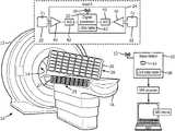
- FIG. 1diagrammatically illustrates a magnetic resonance (MR) imaging device including a wireless MR receive coil and associated RF coil base station.
- MRmagnetic resonance
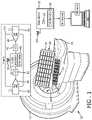
- FIG. 2diagrammatically illustrates a plan view of the wireless MR receive coil of FIG. 1 , with an illustrative FOV and communication links between electronic modules of the wireless MR receive coil operating in a suitable mesh configuration indicated.
- FIG. 3diagrammatically illustrates an enlarged plan view of one-quarter of the wireless MR receive coil of FIG. 1 .
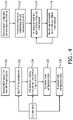
- FIG. 4diagrammatically illustrates a mesh configuration method suitably performed by the wireless MR receive coil and/or the RF coil base station of FIG. 1 .
- an illustrative medical imaging device 10comprises a magnetic resonance (MR) imaging scanner, which in the illustrative example includes a housing or gantry 12 containing various components which are not shown in FIG. 1 , such as by way of non-limiting illustrative example a superconducting or resistive magnet generating a static (B 0 ) magnetic field, magnetic field gradient coils for superimposing magnetic field gradients on the B 0 magnetic field, a whole-body radio frequency (RF) coil for applying RF pulses to excite and/or spatially encode magnetic resonance in an imaging subject disposed in an MR bore 14 or other MR examination region, and/or so forth.
- RFradio frequency
- a robotic patient couch 16 or other subject supportenables loading a medical patient, a subject undergoing a medical screening, or other imaging subject into the MR bore 14 for imaging.
- a wireless MR coil 20is provided for receiving the MR signal generated by operation of the MR imaging scanner 10 .
- FIG. 2shows a plan view of the entire illustrative wireless MR coil 20
- FIG. 3shows an enlarged view of one-fourth of the illustrative wireless MR coil 20 .
- the wireless MR coil 20includes coil elements 22 tuned to receive an MR signal, and electronic modules 24 operatively connected to receive MR signals from the coil elements 22 .
- the illustrative wireless MR coil 20includes 48 coil elements 22 arranged in a 6 ⁇ 8 array; however, it will be appreciated that this arrangement is merely an illustrative example and that more or fewer than 48 coil elements may be used in various arrangements, e.g. by way of a few further non-limiting illustrative examples the wireless MR coil may include a one-dimensional arrangement (i.e.
- the illustrative 48 coil elements 22are arranged on a single support or substrate 26 ; however, as the coil elements disclosed herein are wireless elements it is alternatively contemplated for the coil elements to be arranged on two or more different supports or substrates, e.g.
- the wireless MR coilin another contemplated configuration includes a frontside sub-coil 20 with a first set of MR coil elements on a first (front) substrate 26 and a backside sub-coil 21 (see FIG. 1 ) with a second set of MR coil elements on a second (back) substrate 27 so that the front substrate and its supported coil elements can be placed on a front side of the torso of a patient being imaged, and the back substrate 27 and its supported coil elements can be placed on a back side of the torso of the patient being imaged.
- the wireless MR coil with efficient and configurable communication connectivity as disclosed hereincan be constructed with a wide range of suitable physical layouts or arrangements.
- the wireless MR coilcan be constructed with any suitable form for a chosen type of imaging, e.g. the illustrative wireless MR coil 20 has the shape of a sheet and may, for example, be disposed on, in, or beneath a pallet (not shown) disposed on the subject couch 16 so as to be arranged to perform imaging of the spine, torso, or the like.
- the wireless MR coilcould be shaped to surround a head (i.e., a head coil), to go around a limb (a limb coil), or so forth.
- the coil elements 22are tuned to receive an MR signal generated by precessing isotopes excited by an RF pulse produced by the MR imaging device 10 .
- B 0is the static magnetic field generated by the main magnet of the MR imaging device 10
- ⁇is the gyrometric ratio of the isotope generating the MR signal.
- the coilsare tuned to the frequency of the MR signal by any suitable technique, e.g.
- each electronic module 24includes a transceiver 30 and a digital processor 32 , and each electronic module 24 is operatively connected to receive an MR signal from at least one coil element.
- each illustrative electronic module 24is operatively connected to receive MR signals from two coil elements 22 , as best seen in FIGS. 2 and 3 and as diagrammatically shown in FIG. 1 Inset A.
- FIG. 1 Inset AA non-limiting illustrative operative connection of the two coil elements 22 with the electronic coil module 24 is shown in FIG.
- the number of coil elements operatively coupled with a single electronic modulemay be one, two (as illustrated), three, four, or more; however, in some embodiments to avoid undue wiring complexity and undesirably long connection lengths from the coils to the preamplifiers, the number of coil elements operatively coupled with a single electronic module is preferably no more than four coil elements.
- the digital processor 32may be any suitable programmable digital device or element—for example, the digital processor 32 may be a microprocessor, microcontroller, field programmable gate array (FPGA), or a combination thereof.
- the wireless MR coil 20is a wireless coil that wirelessly transmits the MR signals received by the coil elements 22 off the coil 20 using the transceivers 30 of the electronic modules 24 . Furthermore, it is contemplated for the electronic modules 24 to be powered by energy harvesting (e.g., from the RF and/or magnetic fields generated by the MR scanner 10 ) and/or by on-board rechargeable batteries (not shown) so as to eliminate all wired connections with the system. As such, in some embodiments (including the illustrative embodiment) the wireless MR coil 20 does not include any coaxial cables. In some embodiments (including the illustrative embodiment) the wireless MR coil 20 does not include any optical fibers.
- the wireless MR coil 20does not include any coaxial cables and does not include any optical fibers.
- the wireless MR coilmay include a coaxial cable for receiving electrical power, and/or fiber optical connection for delivering a d.c. signal to detune the coil elements 22 during the RF transmit phase of an MR imaging sequence executed by the MR scanner 10 , or for some other purpose other than transmitting the MR signals received by the coil elements off the coil.
- the transceivers 30 of the electronic modules 24communicate using any suitable low power, short range wireless communication protocol, e.g. ZigBee®, ANTTM, WiFi, BluetoothTM, or so forth.
- a base station 50includes a base station transceiver 52 and a base station digital processor 54 (e.g. a microprocessor, microcontroller, FPGA, or a combination thereof, or so forth) which is programmed to operate the base station transceiver 52 to receive the MR signals wirelessly transmitted to the base station 50 by a configurable mesh network (to be described) formed by the electronic modules 24 of the wireless MR coil 20 .
- the base station 50may include a non-volatile memory (e.g.
- a coil data table 56with information such as the number of MR receive channels (which may in some embodiments correspond to the number of coil elements 22 , e.g. 48 channels in the illustrative example), the wireless network IDs of the electronic modules 24 of the wireless MR coil 20 (e.g. hard coded, or obtained by polling the electronic modules 24 in accord with the chosen wireless communication protocol), and may also store information on the physical layout of the coil elements 22 in order to map the coil elements to a particular MR imaging field of view (FOV).
- FOVMR imaging field of view
- the base station 50receives the wireless MR signals wirelessly transmitted off the coil 20 using the transceivers 30 of the electronic modules 24 .
- the electronic modules 24 of the wireless MR coil 20form a configurable mesh network to wirelessly transmit the MR signals received by the electronic modules 24 to the base station 50 .
- dashed arrowsindicate pairwise links between electronic modules 24 so as to diagrammatically illustrate the configurable mesh network 60 .
- the configurable mesh network 60is configurable at least in that each electronic module 24 is programmable to relay an MR signal from at least one different electronic module 24 to at least one other different electronic module 24 or to the base station 50 .
- FIG. 2to perform this transmission in an efficient and configurable manner, the electronic modules 24 of the wireless MR coil 20 form a configurable mesh network to wirelessly transmit the MR signals received by the electronic modules 24 to the base station 50 .
- dashed arrowsindicate pairwise links between electronic modules 24 so as to diagrammatically illustrate the configurable mesh network 60 .
- the configurable mesh network 60is
- the programming of the illustrative electronic module 24is achieved by way of a links table 62 which stores identification of the other electronic modules for which the illustrative electronic module 24 acts as MR signal relay.
- a links table 62which stores identification of the other electronic modules for which the illustrative electronic module 24 acts as MR signal relay.
- the pairing key or the likemay be stored in the links table 62 .
- the links table 62may, for example, be stored in a flash memory or other non-volatile memory, or in RAM or other volatile memory.
- the wireless communicationmay employ frequency domain multiplexing (FDM), time domain multiplexing (TDM), orthogonal encoding, or another approach for interleaving transmissions between electronic modules 24 and between electronic modules 24 and the base station 50 in frequency space, time, or by orthogonality of the transmitted signals.
- FDMfrequency domain multiplexing
- TDMtime domain multiplexing
- orthogonal encodingor another approach for interleaving transmissions between electronic modules 24 and between electronic modules 24 and the base station 50 in frequency space, time, or by orthogonality of the transmitted signals.
- Configuration of the configurable mesh network 60entails defining which electronic modules serve as relays for which other electronic modules, and which electronic module(s) send MR signal data to the base station 50 .
- the configurable mesh networkmay be configured to achieve various purpose(s) during an imaging sequence, such as to minimize total power to wirelessly transmit the MR signals received by the electronic modules 24 to the base station 50 (and thereby minimize thermal heating introduced by the wireless MR coil 20 and hence enhance patient comfort and safety); to maximize the minimum signal strength of any wireless communication link of the configurable mesh network (and thereby enhance reliability); and/or so forth.
- the base station 50serves as a central coordinator for configuring the configurable mesh network 60 .
- the base station digital processor 54is further programmed to perform mesh configuration operations including: polling the electronic modules 24 of the wireless MR coil 22 using the base station transceiver 52 ; optimizing a mesh configuration of the configurable mesh network 60 respective to at least one operational metric of the wireless MR coil to generate an optimized mesh configuration (where the operational metric of the wireless MR coil 20 is calculated using information determined from the polling); and transmitting a control signal to control the electronic modules 24 of the wireless MR coil 20 to form the configurable mesh network in accord with the optimized mesh configuration.
- the operational metricis chosen to enforce the desired optimization.
- the operational metricmay be ⁇ i ⁇ M ⁇ P i or 1/ ⁇ M
- the operational metricmay be min (S 1 , S 2 , . . . , S L ) or a similar metric, which is to be maximized, where S l is the signal strength of the module-module or module-base station transmission link indexed l and L denotes the total number of such transmission links in the mesh configuration under test.
- the control signal to control the electronic modules 24 of the wireless MR coil 20 to form the configurable mesh network in accord with the optimized mesh configurationmay, for example, be a sequence of pair identifiers identifying the module-module and module-base station pairings to be established to implement the optimized mesh configuration.
- the configurable mesh network 60may be configurable at least in that the electronic modules 24 are configurable to disable coil elements 22 not coupled to an MR imaging field of view (FOV) 64 (see FIG. 2 ).
- the MR imaging FOVmay be smaller than the area covered by the coil elements 22 , so that some coil elements are not (well) coupled with the MR imaging FOV 64 .
- the base station digital processor 54may be further programmed to map the MR imaging FOV (for example, received from the MR imaging device 10 upon the latter being set up to perform a certain imaging sequence) to a set of coil elements of the wireless MR coil 20 and to operate the base station transceiver 52 to transmit a wireless mesh configuration signal to the electronic modules 24 of the wireless MR coil 20 identifying the set of coil elements.
- the mapped coil elementsare those that are (well) coupled with the MR imaging FOV.
- the configurable mesh network 60 of the wireless MR coil 20is then configured with respect to the FOV aspect by the electronic modules 24 disabling those of the coil elements 22 that are not included in the set of coil elements identified as coupled to the FOV by the wireless mesh configuration signal.
- the configurable mesh network 60 shown in FIG. 2is configured in that only the 4 ⁇ 4 array of coil elements within the indicated MR imaging FOV 64 are active (all other coil elements being disabled by the operatively connected electronic modules 24 as part of the mesh configuration). Further, the leftmost four electronic modules 24 of this 4 ⁇ 4 array pair with those four modules next to the right, and so forth, with the rightmost four electronic modules of the 4 ⁇ 4 array pairing with the base station 50 to communicate the MR signals to the base station 50 .
- Such a mesh configurationis efficient in terms of power consumption since the transmission lengths are minimized (thus minimizing the operational metric ⁇ i ⁇ M ⁇ P i ), and is efficient in terms of reliability as the short transmission lengths are expected to have high signal strengths (thus maximizing the operational metric min(S 1 , S 2 , . . . , S L )).
- Thisis merely an illustrative example, and a different mesh configuration may be achieved by optimization for a different operational metric or a different arrangement of the wireless MR receive coil 20 (e.g., if the base station is located “above” the coil in FIG. 2 then the relay links would preferably run from the bottommost electronic modules to the topmost electronic modules which would finally relay to the base station).
- the disclosed approachfacilitates scalability of the imaging area for applications such as whole body imaging.
- the disclosed mesh network MR coil design approachessupport rapid scalability of imaging area for multi-coil applications, and all the coil elements used in a scan do not need to reside in a single physical MR coil.
- a mesh networkcan be made of MR receive elements in multiple MR coils. This is an advantage of the disclosed mesh approach for MR coil design, i.e. the MR receive coil elements can be located in different MR coils across the system, and dynamically combined in a given mesh configuration. This facilitates extension of coil development to non-anatomical coils design, in that one MR coil can support a variety of imaging protocols as long as the coil can receive MR signal sufficient to contribute to the diagnostic image.
- an illustrative operation of the wireless MR coil 20 and base station 50is diagrammed.
- the base station 50receives the MR imaging FOV.
- the MR imaging FOVis mapped to the coil elements that are (well) coupled with the FOV.
- the base station digital processor 54operates the base station transceiver 52 to poll the electronic modules 24 (or, in a variant embodiment, only those modules controlling the coil elements coupled with the MR imaging FOV) to determine information for optimizing the mesh configuration, such as module-module and module-base station pairing signal strengths, per-module power consumption, and/or so forth.
- the base station digital processor 54optimizes the mesh configuration respective to at least one operational metric of the wireless MR coil to generate an optimized mesh configuration.
- this optimizationmay entail only those electronic modules operatively coupled with coil elements used to image the MR imaging FOV.
- the optimized mesh configuration signal(or control signals for implementing the optimized mesh configuration) is broadcast from the base station transceiver 52 to the transceivers 30 of the electronic modules 24 . (Alternatively, a current mesh network of the electronic modules may be utilized to relay this information to the modules to perform the operation 108 ).
- the mesh configuration signalis received at the electronic modules 24 (or at those modules controlling coil elements that are not disabled as not coupled with the FOV), and in an operation 112 the electronic modules 24 form the optimized mesh network by establishing wireless communication links (i.e. module-module links and module-base station links as appropriate to implement the optimized mesh network).
- the electronic moduleswirelessly transmit the received MR signals to the base station 50 using the implemented optimized mesh network.
- the electronic modules 24 and/or the base station 50may monitor signal strengths, module power consumption, or other operational parameters of the wireless MR coil 20 , and if issues are detected (e.g. a link with unacceptably low signal strength, an overheating electronic module, or so forth) the mesh network may be reconfigured to alleviate the detected issue (e.g. by rerouting the mesh network to eliminate the low signal strength link, or by rerouting some mesh network traffic away from the overheating electronic module, or so forth.
- issuese.g. a link with unacceptably low signal strength, an overheating electronic module, or so forth
- the mesh networkmay be reconfigured to alleviate the detected issue (e.g. by rerouting the mesh network to eliminate the low signal strength link, or by rerouting some mesh network traffic away from the overheating electronic module, or so forth.
- the optimized mesh configurationis determined by the base station 50 in operations 102 , 106 , which is an advantageous approach since the base station 50 may typically have greater data processing capacity, and/or more operational power.
- the electronic modules 24may determine or adjust the mesh configuration based on local signal strength measurements, individual module power consumption values, or so forth.
Landscapes
- Physics & Mathematics (AREA)
- Health & Medical Sciences (AREA)
- Condensed Matter Physics & Semiconductors (AREA)
- General Physics & Mathematics (AREA)
- Life Sciences & Earth Sciences (AREA)
- Engineering & Computer Science (AREA)
- Nuclear Medicine, Radiotherapy & Molecular Imaging (AREA)
- Computer Networks & Wireless Communication (AREA)
- Medical Informatics (AREA)
- Surgery (AREA)
- High Energy & Nuclear Physics (AREA)
- Biomedical Technology (AREA)
- Heart & Thoracic Surgery (AREA)
- Radiology & Medical Imaging (AREA)
- Molecular Biology (AREA)
- Pathology (AREA)
- Animal Behavior & Ethology (AREA)
- General Health & Medical Sciences (AREA)
- Public Health (AREA)
- Veterinary Medicine (AREA)
- Biophysics (AREA)
- Magnetic Resonance Imaging Apparatus (AREA)
Abstract
Description
Claims (22)
Priority Applications (1)
| Application Number | Priority Date | Filing Date | Title |
|---|---|---|---|
| US16/766,050US11454685B2 (en) | 2017-11-27 | 2018-11-27 | Mesh networks in wireless MRI RF coil |
Applications Claiming Priority (3)
| Application Number | Priority Date | Filing Date | Title |
|---|---|---|---|
| US201762590716P | 2017-11-27 | 2017-11-27 | |
| PCT/EP2018/082618WO2019102020A1 (en) | 2017-11-27 | 2018-11-27 | Mesh networks in wireless mri rf coil |
| US16/766,050US11454685B2 (en) | 2017-11-27 | 2018-11-27 | Mesh networks in wireless MRI RF coil |
Publications (2)
| Publication Number | Publication Date |
|---|---|
| US20200355766A1 US20200355766A1 (en) | 2020-11-12 |
| US11454685B2true US11454685B2 (en) | 2022-09-27 |
Family
ID=64500403
Family Applications (1)
| Application Number | Title | Priority Date | Filing Date |
|---|---|---|---|
| US16/766,050Active2039-01-29US11454685B2 (en) | 2017-11-27 | 2018-11-27 | Mesh networks in wireless MRI RF coil |
Country Status (5)
| Country | Link |
|---|---|
| US (1) | US11454685B2 (en) |
| EP (1) | EP3717925A1 (en) |
| JP (1) | JP7229245B2 (en) |
| CN (1) | CN111417863B (en) |
| WO (1) | WO2019102020A1 (en) |
Families Citing this family (1)
| Publication number | Priority date | Publication date | Assignee | Title |
|---|---|---|---|---|
| DE102023205673A1 (en) | 2023-06-16 | 2024-12-19 | Siemens Healthineers Ag | local coil with energy-saving device |
Citations (30)
| Publication number | Priority date | Publication date | Assignee | Title |
|---|---|---|---|---|
| US5666055A (en)* | 1995-10-02 | 1997-09-09 | Jones; Randall W. | Surface coil system for a single channel NMR receiver |
| US7176689B2 (en)* | 2001-12-14 | 2007-02-13 | Kabushiki Kaisha Toshiba | Parallel MR imaging with use of multi-coil made of plural element coils |
| US20070210793A1 (en)* | 2006-02-20 | 2007-09-13 | Berthold Kiefer | Method and multi-reception coil mr apparatus for generating an mr image using data from selected coils |
| US20080129296A1 (en)* | 2006-11-22 | 2008-06-05 | Hubertus Fischer | Radio-frequency coil arrangement |
| US20080143332A1 (en)* | 2006-12-13 | 2008-06-19 | Martin Hergt | Magnetic resonance system with coupling between a base unit and a local coil at the patient bed |
| US20080197849A1 (en)* | 2005-11-28 | 2008-08-21 | Oliver Heid | Magnetic Resonance System Having a Base Body and a Patient Bed and Inductive or Capacitive Signal Transmission |
| US20080246477A1 (en)* | 2007-04-06 | 2008-10-09 | Kabushiki Kaisha Toshiba | Magnetic resonance imaging apparatus, RF coil system, and magnetic resonance imaging method |
| US7535230B2 (en)* | 2007-03-08 | 2009-05-19 | Kabushiki Kaisha Toshiba | Magnetic resonance imaging apparatus and magnetic resonance imaging method |
| US20090224761A1 (en)* | 2008-03-10 | 2009-09-10 | Kabushiki Kaisha Toshiba | Magnetic resonance imaging apparatus and magnetic resonance imaging method |
| US7696752B2 (en)* | 2006-07-12 | 2010-04-13 | Kabushiki Kaisha Toshiba | Magnetic resonance imaging apparatus |
| US20100176809A1 (en)* | 2009-01-09 | 2010-07-15 | Stephan Biber | Magnetic resonance tomography device with localization system and method to localize a local coil |
| US20110031970A1 (en)* | 2006-12-28 | 2011-02-10 | Atsushi Ninomiya | Magnetic Resonance Imaging Apparatus |
| US20110103491A1 (en) | 2008-06-04 | 2011-05-05 | Koninklijke Philips Electronics N.V. | Adaptive data rate control |
| US8188743B2 (en)* | 2008-09-09 | 2012-05-29 | Kabushiki Kaisha Toshiba | Magnetic resonance imaging apparatus and control method of magnetic resonance imaging apparatus |
| US20120249135A1 (en)* | 2011-03-31 | 2012-10-04 | Andre Albsmeier | Local coil system |
| US20120306494A1 (en)* | 2011-05-31 | 2012-12-06 | General Electric Company | Magnetic resonance system and method thereof |
| US20120319689A1 (en)* | 2010-08-16 | 2012-12-20 | Toshiba Medical Systems Corporation | Magnetic resonance imaging apparatus |
| US20130200894A1 (en) | 2011-07-29 | 2013-08-08 | Siemens Aktiengesellschaft | Adaptive energy transfer to a local coil system |
| US20130241547A1 (en) | 2011-09-06 | 2013-09-19 | Siemens Aktiengesellschaft | Magnetic resonance apparatus having receive coils and method for operating a magnetic resonance apparatus |
| US20140091791A1 (en)* | 2012-09-28 | 2014-04-03 | General Electric Company | System and Method for Inductively Communicating Data |
| US20140184222A1 (en)* | 2012-12-27 | 2014-07-03 | General Electric Company | Matrix shim coil apparatus |
| US20140218034A1 (en)* | 2013-01-16 | 2014-08-07 | Toshiba Medical Systems Corporation | Magnetic resonance imaging apparatus and rf coil device |
| US20140361769A1 (en)* | 2013-06-05 | 2014-12-11 | Donald Hardie | Signal Transmissions to and from a Local Coil of a Magnetic Resonance System |
| US8981777B2 (en)* | 2010-01-13 | 2015-03-17 | Siemens Aktiengesellschaft | Spine coil array |
| US20150192651A1 (en) | 2014-01-07 | 2015-07-09 | Michael Wiehl | Receiving Apparatus for Receiving a Useful Signal |
| US20160109541A1 (en) | 2013-06-21 | 2016-04-21 | Kabushiki Kaisha Toshiba | Mri apparatus |
| US20160154074A1 (en)* | 2014-11-27 | 2016-06-02 | Kabushiki Kaisha Toshiba | Magnetic resonance imaging apparatus |
| US20170093170A1 (en)* | 2015-09-25 | 2017-03-30 | Intel Corporation | Detecting resonant frequencies |
| US20170252578A1 (en)* | 2014-09-01 | 2017-09-07 | Koninklijke Philips N.V. | Magnetic resonance imaging receive coil with reduced radiation attenuation |
| US10353024B2 (en)* | 2015-11-30 | 2019-07-16 | Toshiba Medical Systems Corporation | Magnetic resonance imaging apparatus |
Family Cites Families (14)
| Publication number | Priority date | Publication date | Assignee | Title |
|---|---|---|---|---|
| WO2006008665A1 (en)* | 2004-07-15 | 2006-01-26 | Koninklijke Philips Electronics, N.V. | Wireless mr receiving coil system |
| WO2006075214A2 (en) | 2004-12-06 | 2006-07-20 | Koninklijke Philips Electronics N.V. | Frequency domain multiplexed transmission of mr signals from a receiver coil array |
| TW200637383A (en)* | 2005-03-11 | 2006-10-16 | Interdigital Tech Corp | Method and system for conserving battery power of mesh points in a mesh network |
| US20060253735A1 (en) | 2005-03-11 | 2006-11-09 | Interdigital Technology Corporation | Method and system for conserving battery power of mesh points in a mesh network |
| JP5274864B2 (en)* | 2007-04-06 | 2013-08-28 | 株式会社東芝 | Magnetic resonance imaging apparatus, RF coil system, and magnetic resonance imaging method |
| DE102009052197B4 (en)* | 2009-11-06 | 2013-06-13 | Siemens Aktiengesellschaft | MR signal transmission in a local coil arrangement |
| CN101924399B (en)* | 2010-04-12 | 2012-09-05 | 武汉大学 | Relay wireless power supply system based on magnetic resonance |
| DE102011006509B4 (en)* | 2011-03-31 | 2016-05-12 | Siemens Aktiengesellschaft | Local coil system, magnetic resonance system and method for transmitting signals from a local coil |
| DE102012210507B4 (en)* | 2012-06-21 | 2016-06-16 | Siemens Healthcare Gmbh | Local coil for a magnetic resonance imaging system and magnetic resonance imaging system |
| JP6104712B2 (en)* | 2013-05-28 | 2017-03-29 | 東芝メディカルシステムズ株式会社 | Magnetic resonance imaging system |
| EP3117230B1 (en)* | 2014-03-13 | 2021-05-26 | Koninklijke Philips N.V. | Magnetic resonance antenna with electronic dosimeters |
| US10361586B2 (en)* | 2015-12-29 | 2019-07-23 | Motorola Solutions, Inc. | Method of wirelessly transferring power |
| CN206209085U (en)* | 2016-08-31 | 2017-05-31 | 沈阳东软医疗系统有限公司 | Local coil and magnetic resonance imaging system in magnetic resonance imaging system |
| CN106772161B (en)* | 2017-02-28 | 2019-04-30 | 吉林大学 | Multi-channel array receiving coil and detection method for wireless sensor network |
- 2018
- 2018-11-27USUS16/766,050patent/US11454685B2/enactiveActive
- 2018-11-27JPJP2020528377Apatent/JP7229245B2/enactiveActive
- 2018-11-27CNCN201880076659.1Apatent/CN111417863B/enactiveActive
- 2018-11-27EPEP18811004.3Apatent/EP3717925A1/enactivePending
- 2018-11-27WOPCT/EP2018/082618patent/WO2019102020A1/ennot_activeCeased
Patent Citations (35)
| Publication number | Priority date | Publication date | Assignee | Title |
|---|---|---|---|---|
| US5666055A (en)* | 1995-10-02 | 1997-09-09 | Jones; Randall W. | Surface coil system for a single channel NMR receiver |
| US7176689B2 (en)* | 2001-12-14 | 2007-02-13 | Kabushiki Kaisha Toshiba | Parallel MR imaging with use of multi-coil made of plural element coils |
| US20080197849A1 (en)* | 2005-11-28 | 2008-08-21 | Oliver Heid | Magnetic Resonance System Having a Base Body and a Patient Bed and Inductive or Capacitive Signal Transmission |
| US20070210793A1 (en)* | 2006-02-20 | 2007-09-13 | Berthold Kiefer | Method and multi-reception coil mr apparatus for generating an mr image using data from selected coils |
| US7696752B2 (en)* | 2006-07-12 | 2010-04-13 | Kabushiki Kaisha Toshiba | Magnetic resonance imaging apparatus |
| US20080129296A1 (en)* | 2006-11-22 | 2008-06-05 | Hubertus Fischer | Radio-frequency coil arrangement |
| US20080143332A1 (en)* | 2006-12-13 | 2008-06-19 | Martin Hergt | Magnetic resonance system with coupling between a base unit and a local coil at the patient bed |
| US7486077B2 (en)* | 2006-12-13 | 2009-02-03 | Siemens Aktiengesellschaft | Magnetic resonance system with coupling between a base unit and a local coil at the patient bed |
| US20110031970A1 (en)* | 2006-12-28 | 2011-02-10 | Atsushi Ninomiya | Magnetic Resonance Imaging Apparatus |
| US7535230B2 (en)* | 2007-03-08 | 2009-05-19 | Kabushiki Kaisha Toshiba | Magnetic resonance imaging apparatus and magnetic resonance imaging method |
| US7619415B2 (en)* | 2007-04-06 | 2009-11-17 | Kabushiki Kaisha Toshiba | Magnetic resonance imaging apparatus, RF coil system, and magnetic resonance imaging method |
| US20080246477A1 (en)* | 2007-04-06 | 2008-10-09 | Kabushiki Kaisha Toshiba | Magnetic resonance imaging apparatus, RF coil system, and magnetic resonance imaging method |
| US20090224761A1 (en)* | 2008-03-10 | 2009-09-10 | Kabushiki Kaisha Toshiba | Magnetic resonance imaging apparatus and magnetic resonance imaging method |
| US20110103491A1 (en) | 2008-06-04 | 2011-05-05 | Koninklijke Philips Electronics N.V. | Adaptive data rate control |
| US8188743B2 (en)* | 2008-09-09 | 2012-05-29 | Kabushiki Kaisha Toshiba | Magnetic resonance imaging apparatus and control method of magnetic resonance imaging apparatus |
| US20100176809A1 (en)* | 2009-01-09 | 2010-07-15 | Stephan Biber | Magnetic resonance tomography device with localization system and method to localize a local coil |
| US8981777B2 (en)* | 2010-01-13 | 2015-03-17 | Siemens Aktiengesellschaft | Spine coil array |
| US20120319689A1 (en)* | 2010-08-16 | 2012-12-20 | Toshiba Medical Systems Corporation | Magnetic resonance imaging apparatus |
| US20120249135A1 (en)* | 2011-03-31 | 2012-10-04 | Andre Albsmeier | Local coil system |
| US20120306494A1 (en)* | 2011-05-31 | 2012-12-06 | General Electric Company | Magnetic resonance system and method thereof |
| US20130200894A1 (en) | 2011-07-29 | 2013-08-08 | Siemens Aktiengesellschaft | Adaptive energy transfer to a local coil system |
| US20130241547A1 (en) | 2011-09-06 | 2013-09-19 | Siemens Aktiengesellschaft | Magnetic resonance apparatus having receive coils and method for operating a magnetic resonance apparatus |
| US9513352B2 (en)* | 2012-09-28 | 2016-12-06 | General Electric Company | System and method for inductively communicating data |
| US20140091791A1 (en)* | 2012-09-28 | 2014-04-03 | General Electric Company | System and Method for Inductively Communicating Data |
| US20140184222A1 (en)* | 2012-12-27 | 2014-07-03 | General Electric Company | Matrix shim coil apparatus |
| US20140218034A1 (en)* | 2013-01-16 | 2014-08-07 | Toshiba Medical Systems Corporation | Magnetic resonance imaging apparatus and rf coil device |
| US9817091B2 (en)* | 2013-01-16 | 2017-11-14 | Toshiba Medical Systems Corporation | Magnetic resonance imaging apparatus and RF coil device |
| US9733322B2 (en)* | 2013-06-05 | 2017-08-15 | Siemens Aktiengesellschaft | Signal transmissions to and from a local coil of a magnetic resonance system |
| US20140361769A1 (en)* | 2013-06-05 | 2014-12-11 | Donald Hardie | Signal Transmissions to and from a Local Coil of a Magnetic Resonance System |
| US20160109541A1 (en) | 2013-06-21 | 2016-04-21 | Kabushiki Kaisha Toshiba | Mri apparatus |
| US20150192651A1 (en) | 2014-01-07 | 2015-07-09 | Michael Wiehl | Receiving Apparatus for Receiving a Useful Signal |
| US20170252578A1 (en)* | 2014-09-01 | 2017-09-07 | Koninklijke Philips N.V. | Magnetic resonance imaging receive coil with reduced radiation attenuation |
| US20160154074A1 (en)* | 2014-11-27 | 2016-06-02 | Kabushiki Kaisha Toshiba | Magnetic resonance imaging apparatus |
| US20170093170A1 (en)* | 2015-09-25 | 2017-03-30 | Intel Corporation | Detecting resonant frequencies |
| US10353024B2 (en)* | 2015-11-30 | 2019-07-16 | Toshiba Medical Systems Corporation | Magnetic resonance imaging apparatus |
Non-Patent Citations (2)
| Title |
|---|
| Elsami et al. "A Survey on Wireless Mesh Networks: Architecture, Specifications and Challenges" 2014 IEEE 5th Control ans System Graduate Research Colloquium, Aug. 11-12, 2014. |
| International Search Report and Written Opinion from PCT/EP2018/082618 dated Mar. 4, 2019. |
Also Published As
| Publication number | Publication date |
|---|---|
| US20200355766A1 (en) | 2020-11-12 |
| JP7229245B2 (en) | 2023-02-27 |
| CN111417863A (en) | 2020-07-14 |
| WO2019102020A1 (en) | 2019-05-31 |
| CN111417863B (en) | 2024-04-16 |
| EP3717925A1 (en) | 2020-10-07 |
| JP2021504018A (en) | 2021-02-15 |
Similar Documents
| Publication | Publication Date | Title |
|---|---|---|
| US9689940B2 (en) | Local coil system, transmitting device, magnetic resonance system and method for the wireless transfer of energy to a local coil system | |
| US9513352B2 (en) | System and method for inductively communicating data | |
| EP2807497B1 (en) | Multi-resonant t/r antenna for mr image generation | |
| CN101405612B (en) | Shielded multix coil array for parallel high field MRI | |
| US9535142B2 (en) | Multichannel RF volume resonator for MRI | |
| US10948557B2 (en) | MRI RF coil assemblies with RF coil elements that allow wireless communication data transmission and related methods and systems | |
| US8035384B2 (en) | Hybrid birdcage-TEM radio frequency (RF) coil for multinuclear MRI/MRS | |
| JP5048647B2 (en) | Antenna having a communication unit and picking up magnetic resonance signals | |
| US10060994B2 (en) | Z-segmented radio frequency antenna device for magnetic resonance imaging | |
| US20120268132A1 (en) | Magnetic Resonance Signal Detection Using Remotely Positioned Receive Coils | |
| US20120161767A1 (en) | System and method for inductively communicating data | |
| US20100265020A1 (en) | Radio frequency (rf) coil array with double asymmetric saddle coil pairs | |
| CN102736041B (en) | The method of the signal of local coil system, magnetic resonance system and transmission local coil | |
| JP2010269130A (en) | Magnetic resonance imaging apparatus and RF coil | |
| KR101892976B1 (en) | Mr-body coil | |
| CN103135080A (en) | Magnetic resonance antenna arrangement and magnetic resonance device | |
| JP2014046094A (en) | Magnetic resonance imaging apparatus, and digital radio communication device | |
| US20080161675A1 (en) | Ultra-Short Mri Body Coil | |
| CN104122517A (en) | Antenna device for magnetic resonance tomography system | |
| US11454685B2 (en) | Mesh networks in wireless MRI RF coil | |
| CN209878976U (en) | Body coil for magnetic resonance system, scanning device and magnetic resonance imaging system | |
| CN110869789B (en) | Passive RF shim resonator for field homogenization of RF antenna devices for TX and RX modes | |
| US20120182013A1 (en) | Antenna arrangement for magnetic resonance applications | |
| CN120722258A (en) | Magnetic resonance system and radio frequency local coil for a magnetic resonance system |
Legal Events
| Date | Code | Title | Description |
|---|---|---|---|
| AS | Assignment | Owner name:KONINKLIJKE PHILIPS N.V., NETHERLANDS Free format text:ASSIGNMENT OF ASSIGNORS INTEREST;ASSIGNORS:REDDER, PAUL FRANZ;REYKOWSKI, ARNE;CANDERON RICO, RODRIGO;SIGNING DATES FROM 20181212 TO 20181219;REEL/FRAME:052724/0926 | |
| FEPP | Fee payment procedure | Free format text:ENTITY STATUS SET TO UNDISCOUNTED (ORIGINAL EVENT CODE: BIG.); ENTITY STATUS OF PATENT OWNER: LARGE ENTITY | |
| STPP | Information on status: patent application and granting procedure in general | Free format text:APPLICATION DISPATCHED FROM PREEXAM, NOT YET DOCKETED | |
| STPP | Information on status: patent application and granting procedure in general | Free format text:DOCKETED NEW CASE - READY FOR EXAMINATION | |
| STPP | Information on status: patent application and granting procedure in general | Free format text:NON FINAL ACTION MAILED | |
| STPP | Information on status: patent application and granting procedure in general | Free format text:RESPONSE TO NON-FINAL OFFICE ACTION ENTERED AND FORWARDED TO EXAMINER | |
| STPP | Information on status: patent application and granting procedure in general | Free format text:FINAL REJECTION MAILED | |
| STCV | Information on status: appeal procedure | Free format text:NOTICE OF APPEAL FILED | |
| STPP | Information on status: patent application and granting procedure in general | Free format text:RESPONSE TO NON-FINAL OFFICE ACTION ENTERED AND FORWARDED TO EXAMINER | |
| STPP | Information on status: patent application and granting procedure in general | Free format text:NOTICE OF ALLOWANCE MAILED -- APPLICATION RECEIVED IN OFFICE OF PUBLICATIONS | |
| STPP | Information on status: patent application and granting procedure in general | Free format text:PUBLICATIONS -- ISSUE FEE PAYMENT VERIFIED | |
| STCF | Information on status: patent grant | Free format text:PATENTED CASE |