US11447407B2 - Systems for controlled treatment of water with ozone and related methods therefor - Google Patents
Systems for controlled treatment of water with ozone and related methods thereforDownload PDFInfo
- Publication number
- US11447407B2 US11447407B2US16/630,824US201816630824AUS11447407B2US 11447407 B2US11447407 B2US 11447407B2US 201816630824 AUS201816630824 AUS 201816630824AUS 11447407 B2US11447407 B2US 11447407B2
- Authority
- US
- United States
- Prior art keywords
- ozone
- water
- generated
- proximal
- generating unit
- Prior art date
- Legal status (The legal status is an assumption and is not a legal conclusion. Google has not performed a legal analysis and makes no representation as to the accuracy of the status listed.)
- Active, expires
Links
Images


Classifications
- C—CHEMISTRY; METALLURGY
- C02—TREATMENT OF WATER, WASTE WATER, SEWAGE, OR SLUDGE
- C02F—TREATMENT OF WATER, WASTE WATER, SEWAGE, OR SLUDGE
- C02F1/00—Treatment of water, waste water, or sewage
- C02F1/72—Treatment of water, waste water, or sewage by oxidation
- C02F1/78—Treatment of water, waste water, or sewage by oxidation with ozone
- C—CHEMISTRY; METALLURGY
- C02—TREATMENT OF WATER, WASTE WATER, SEWAGE, OR SLUDGE
- C02F—TREATMENT OF WATER, WASTE WATER, SEWAGE, OR SLUDGE
- C02F1/00—Treatment of water, waste water, or sewage
- C02F1/008—Control or steering systems not provided for elsewhere in subclass C02F
- E—FIXED CONSTRUCTIONS
- E03—WATER SUPPLY; SEWERAGE
- E03B—INSTALLATIONS OR METHODS FOR OBTAINING, COLLECTING, OR DISTRIBUTING WATER
- E03B3/00—Methods or installations for obtaining or collecting drinking water or tap water
- E03B3/28—Methods or installations for obtaining or collecting drinking water or tap water from humid air
- B—PERFORMING OPERATIONS; TRANSPORTING
- B01—PHYSICAL OR CHEMICAL PROCESSES OR APPARATUS IN GENERAL
- B01D—SEPARATION
- B01D53/00—Separation of gases or vapours; Recovering vapours of volatile solvents from gases; Chemical or biological purification of waste gases, e.g. engine exhaust gases, smoke, fumes, flue gases, aerosols
- B01D53/26—Drying gases or vapours
- C—CHEMISTRY; METALLURGY
- C02—TREATMENT OF WATER, WASTE WATER, SEWAGE, OR SLUDGE
- C02F—TREATMENT OF WATER, WASTE WATER, SEWAGE, OR SLUDGE
- C02F2201/00—Apparatus for treatment of water, waste water or sewage
- C02F2201/009—Apparatus with independent power supply, e.g. solar cells, windpower or fuel cells
- C—CHEMISTRY; METALLURGY
- C02—TREATMENT OF WATER, WASTE WATER, SEWAGE, OR SLUDGE
- C02F—TREATMENT OF WATER, WASTE WATER, SEWAGE, OR SLUDGE
- C02F2201/00—Apparatus for treatment of water, waste water or sewage
- C02F2201/78—Details relating to ozone treatment devices
- C02F2201/782—Ozone generators
- C—CHEMISTRY; METALLURGY
- C02—TREATMENT OF WATER, WASTE WATER, SEWAGE, OR SLUDGE
- C02F—TREATMENT OF WATER, WASTE WATER, SEWAGE, OR SLUDGE
- C02F2209/00—Controlling or monitoring parameters in water treatment
- C02F2209/02—Temperature
- C—CHEMISTRY; METALLURGY
- C02—TREATMENT OF WATER, WASTE WATER, SEWAGE, OR SLUDGE
- C02F—TREATMENT OF WATER, WASTE WATER, SEWAGE, OR SLUDGE
- C02F2209/00—Controlling or monitoring parameters in water treatment
- C02F2209/23—O3
- Y—GENERAL TAGGING OF NEW TECHNOLOGICAL DEVELOPMENTS; GENERAL TAGGING OF CROSS-SECTIONAL TECHNOLOGIES SPANNING OVER SEVERAL SECTIONS OF THE IPC; TECHNICAL SUBJECTS COVERED BY FORMER USPC CROSS-REFERENCE ART COLLECTIONS [XRACs] AND DIGESTS
- Y02—TECHNOLOGIES OR APPLICATIONS FOR MITIGATION OR ADAPTATION AGAINST CLIMATE CHANGE
- Y02A—TECHNOLOGIES FOR ADAPTATION TO CLIMATE CHANGE
- Y02A20/00—Water conservation; Efficient water supply; Efficient water use
- Y02A20/20—Controlling water pollution; Waste water treatment
- Y02A20/208—Off-grid powered water treatment
- Y02A20/212—Solar-powered wastewater sewage treatment, e.g. spray evaporation
Definitions
- the present disclosureis related to ozone-based treatment techniques and, more particularly, to techniques that utilize ozone for treating and sanitizing water and/or other substances.
- FIG. 1illustrates a front elevational view of an exemplary computer system that is suitable to implement at least part of an ozone generator control system of the system of FIG. 3 , and/or to implement at least part of one or more of the activities of the method of FIG. 10 or one or more other methods described herein;
- FIG. 2illustrates a representative block diagram of exemplary elements included on the circuit boards inside a chassis of the computer system of FIG. 1 ;
- FIG. 3illustrates a representative block diagram of a system, according to an embodiment
- FIG. 4illustrates a representative block diagram of an ozone generator of the system of FIG. 3 , according to the embodiment of FIG. 3 ;
- FIG. 5illustrates a representative block diagram of an ozone generator control system of the ozone generator of FIG. 4 , according to the embodiment of FIG. 3 ;
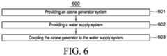
- FIG. 6illustrates a flow chart for a method of providing a system, according to an embodiment
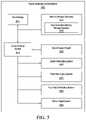
- FIG. 7illustrates a flow chart for an exemplary activity of providing an ozone generator system, according to the embodiment of FIG. 6 ;
- FIG. 8illustrates a flow chart for an exemplary activity of providing an ozone generator control system, according to the embodiment of FIG. 6 ;
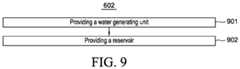
- FIG. 9illustrates a flow chart for an exemplary activity of providing a water supply system, according to the embodiment of FIG. 6 ;
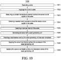
- FIG. 10illustrates a flow chart for an embodiment of a method
- FIG. 11illustrates a flow chart for an exemplary activity of generating ozone, according to the embodiment of FIG. 10 ;
- FIG. 12illustrates a flow chart for an exemplary activity of controlling a quantity of the ozone generated, according to the embodiment of FIG. 10 ;
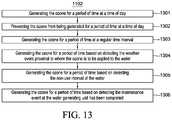
- FIG. 13illustrates a flow chart for an exemplary activity of controlling when the ozone is generated, according to the embodiment of FIG. 10 .
- Coupleshould be broadly understood and refer to connecting two or more elements or signals, electrically, mechanically and/or otherwise.
- Two or more electrical elementsmay be electrically coupled together, but not be mechanically or otherwise coupled together; two or more mechanical elements may be mechanically coupled together, but not be electrically or otherwise coupled together; two or more electrical elements may be mechanically coupled together, but not be electrically or otherwise coupled together.
- Couplingmay be for any length of time, e.g., permanent or semi-permanent or only for an instant.
- Electrode couplingand the like should be broadly understood and include coupling involving any electrical signal, whether a power signal, a data signal, and/or other types or combinations of electrical signals.
- Mechanical couplingand the like should be broadly understood and include mechanical coupling of all types.
- “approximately”can, in some embodiments, mean within plus or minus ten percent of the stated value. In other embodiments, “approximately” can mean within plus or minus five percent of the stated value. In further embodiments, “approximately” can mean within plus or minus three percent of the stated value. In yet other embodiments, “approximately” can mean within plus or minus one percent of the stated value.
- a systemcomprising: one or more processors; and one or more non-transitory memory storage devices storing computer instructions configured to run on the one or more processors and perform: generating ozone; and applying the ozone to water; wherein: generating the ozone comprises: controlling a quantity of the ozone generated; and controlling when the ozone is generated.
- a methodis disclosed which is implemented via execution of computer instructions configured to run at one or more processors and configured to be stored at one or more non-transitory memory storage devices, the method comprising: generating ozone; and applying the ozone to water; wherein: generating the ozone comprises: controlling a quantity of the ozone generated; and controlling when the ozone is generated.
- a systemcomprising: a water supply system configured to make water available to a user; and an ozone generator system configured to generate ozone and apply the ozone to the water prior to use of the water by the user; wherein: the water supply system comprises a water generating unit; the ozone generator system comprises an ozone generator control system; and the ozone generator control system is configured to control a quantity of the ozone generated and when the ozone is generated.
- FIG. 1illustrates an exemplary embodiment of a computer system 100 , all of which or a portion of which can be suitable for (i) implementing part or all of one or more embodiments of the techniques, methods, and systems and/or (ii) implementing and/or operating part or all of one or more embodiments of the memory storage devices described herein.
- computer system 100can be suitable for implementing part or all of one or more embodiments of the techniques, methods, and/or systems described herein.
- one or more elements of computer system 100e.g., a refreshing monitor 106 , a keyboard 104 , and/or a mouse 110 , etc.
- computer system 100also can be appropriate for implementing part or all of one or more embodiments of the techniques, methods, and/or systems described herein.
- computer system 100can comprise chassis 102 containing one or more circuit boards (not shown), a Universal Serial Bus (USB) port 112 , a hard drive 114 , and an optical disc drive 116 .
- optical disc drive 116can comprise a Compact Disc Read-Only Memory (CD-ROM), a Digital Video Disc (DVD) drive, or a Blu-ray drive.
- a different or separate one of a chassis 102 (and its internal components)can be suitable for implementing part or all of one or more embodiments of the techniques, methods, and/or systems described herein.
- FIG. 2illustrates a representative block diagram of exemplary elements included on the circuit boards inside chassis 102 ( FIG. 2 ).
- a central processing unit (CPU) 210is coupled to a system bus 214 .
- the architecture of CPU 210can be compliant with any of a variety of commercially distributed architecture families.
- system bus 214also is coupled to a memory storage unit 208 , where memory storage unit 208 can comprise (i) non-volatile memory, such as, for example, read only memory (ROM) and/or (ii) volatile memory, such as, for example, random access memory (RAM).
- non-volatile memorysuch as, for example, read only memory (ROM) and/or (ii) volatile memory, such as, for example, random access memory (RAM).
- ROMread only memory
- RAMrandom access memory
- the non-volatile memorycan be removable and/or non-removable non-volatile memory.
- RAMcan include dynamic RAM (DRAM), static RAM (SRAM), etc.
- ROMcan include mask-programmed ROM, programmable ROM (PROM), one-time programmable ROM (OTP), erasable programmable read-only memory (EPROM), electrically erasable programmable ROM (EEPROM) (e.g., electrically alterable ROM (EAROM) and/or flash memory), etc.
- PROMprogrammable ROM
- OTPone-time programmable ROM
- EPROMerasable programmable read-only memory
- EEPROMelectrically erasable programmable ROM
- memory storage unit 208can comprise (i) non-transitory memory and/or (ii) transitory memory.
- the memory storage device(s) of the various embodiments disclosed hereincan comprise memory storage unit 208 , an external memory storage drive (not shown), such as, for example, a USB-equipped electronic memory storage drive coupled to universal serial bus (USB) port 112 ( FIGS. 1 & 2 ), hard drive 114 ( FIGS. 1 & 2 ), optical disc drive 116 ( FIGS. 1 & 2 ), a floppy disk drive (not shown), etc.
- USBuniversal serial bus
- non-volatile and/or non-transitory memory storage device(s)refer to the portions of the memory storage device(s) that are non-volatile and/or non-transitory memory.
- portions of the memory storage device(s) of the various embodiments disclosed hereincan be encoded with a boot code sequence suitable for restoring computer system 100 ( FIG. 1 ) to a functional state after a system reset.
- portions of the memory storage device(s) of the various embodiments disclosed hereincan comprise microcode such as a Basic Input-Output System (BIOS) or Unified Extensible Firmware Interface (UEFI) operable with computer system 100 ( FIG. 1 ).
- BIOSBasic Input-Output System
- UEFIUnified Extensible Firmware Interface
- portions of the memory storage device(s) of the various embodiments disclosed hereincan comprise an operating system, which can be a software program that manages the hardware and software resources of a computer and/or a computer network. Meanwhile, the operating system can perform basic tasks such as, for example, controlling and allocating memory, prioritizing the processing of instructions, controlling input and output devices, facilitating networking, and managing files.
- Exemplary operating systemscan comprise (i) Microsoft® Windows® operating system (OS) by Microsoft Corp. of Redmond, Wash., United States of America, (ii) Mac® OS by Apple Inc.
- exemplary operating systemscan comprise (i) iOSTM by Apple Inc. of Cupertino, Calif., United States of America, (ii) the Blackberry® OS by Research In Motion (RIM) of Waterloo, Ontario, Canada, (iii) the AndroidTM OS developed by the Open Handset Alliance, or (iv) the Windows MobileTM OS by Microsoft Corp. of Redmond, Wash., United States of America.
- the term “computer network”can refer to a collection of computers and devices interconnected by communications channels that facilitate communications among users and allow users to share resources (e.g., an internet connection, an Ethernet connection, etc.).
- the computers and devicescan be interconnected according to any conventional network topology (e.g., bus, star, tree, linear, ring, mesh, etc.).
- processormeans any type of computational circuit, such as but not limited to a microprocessor, a microcontroller, a controller, a complex instruction set computing (CISC) microprocessor, a reduced instruction set computing (RISC) microprocessor, a very long instruction word (VLIW) microprocessor, a graphics processor, a digital signal processor, or any other type of processor or processing circuit capable of performing the desired functions.
- CISCcomplex instruction set computing
- RISCreduced instruction set computing
- VLIWvery long instruction word
- the one or more processors of the various embodiments disclosed hereincan comprise CPU 210 .
- various I/O devicessuch as a disk controller 204 , a graphics adapter 224 , a video controller 202 , a keyboard adapter 226 , a mouse adapter 206 , a network adapter 220 , and other I/O devices 222 can be coupled to system bus 214 .
- Keyboard adapter 226 and mouse adapter 206are coupled to keyboard 104 ( FIGS. 1 & 2 ) and mouse 110 ( FIGS. 1 & 2 ), respectively, of computer system 100 ( FIG. 1 ).
- graphics adapter 224 and video controller 202are indicated as distinct units in FIG. 2
- video controller 202can be integrated into graphics adapter 224 , or vice versa in other embodiments.
- Video controller 202is suitable for refreshing monitor 106 ( FIGS. 1 & 2 ) to display images on a screen 108 ( FIG. 1 ) of computer system 100 ( FIG. 1 ).
- Disk controller 204can control hard drive 114 ( FIGS. 1 & 2 ), USB port 112 ( FIGS. 1 & 2 ), and CD-ROM drive 116 ( FIGS. 1 & 2 ). In other embodiments, distinct units can be used to control each of these devices separately.
- Network adapter 220can be suitable to connect computer system 100 ( FIG. 1 ) to a computer network by wired communication (e.g., a wired network adapter) and/or wireless communication (e.g., a wireless network adapter).
- network adapter 220can be plugged or coupled to an expansion port (not shown) in computer system 100 ( FIG. 1 ).
- network adapter 220can be built into computer system 100 ( FIG. 1 ).
- network adapter 220can be built into computer system 100 ( FIG. 1 ).
- FIG. 1although many other components of computer system 100 are not shown, such components and their interconnection are well known to those of ordinary skill in the art. Accordingly, further details concerning the construction and composition of computer system 100 and the circuit boards inside chassis 102 are not discussed herein.
- program instructionse.g., computer instructions
- CPU 210FIG. 2
- computer system 100can be reprogrammed with one or more systems, applications, and/or databases to convert computer system 100 from a general purpose computer to a special purpose computer.
- computer system 100is illustrated as a desktop computer in FIG. 1 , in many examples, system 100 can have a different form factor while still having functional elements similar to those described for computer system 100 .
- computer system 100may comprise a single computer, a single server, or a cluster or collection of computers or servers, or a cloud of computers or servers. Typically, a cluster or collection of servers can be used when the demand on computer system 100 exceeds the reasonable capability of a single server or computer.
- computer system 100may comprise an embedded system.
- FIG. 3illustrates a representative block diagram of a system 300 , according to an embodiment.
- System 300is merely exemplary and embodiments of the system are not limited to the embodiments presented herein.
- System 300can be employed in many different embodiments or examples not specifically depicted or described herein.
- certain elements of system 300can perform various methods and/or activities of those methods. In these or other embodiments, the methods and/or the activities of the methods can be performed by other suitable elements of system 300 .
- system 300can make available water to a user of system 300 .
- system 300can generate the water to make available the water to the user of system 300 .
- system 300can generate ozone and apply the ozone to one or more substances (e.g., water).
- system 300can control treatment of the substance(s) (e.g., water) with the ozone, such as, for example, to optimize treatment of the substance(s) (e.g., water) with the ozone.
- system 300can control a quantity of the ozone generated, and/or when the ozone is generated.
- system 300can sanitize water made available to a user of system 300 , such as, for example, to make the water potable.
- system 300can sanitize one or more interior surfaces of a water supply system (e.g., water supply system 301 ( FIG. 3 )).
- system 300can be implemented with hardware and/or software, as described herein.
- at least part of the hardware and/or softwarecan be conventional, while in these or other embodiments, part or all of the hardware and/or software can be customized (e.g., optimized) for implementing part or all of the functionality of system 300 described herein.
- System 300comprises an ozone generator system 302 .
- system 300also can comprise a water supply system 301 .
- ozone generator system 302can be coupled to water supply system 301 .
- water supply system 301can be omitted.
- Water supply system 301can make available water to a user of system 300 .
- water supply system 301can comprise any suitable system configured to make available water to the user of system 300 .
- water supply system 301can comprise a public water supply or a water collector (e.g., a rain collector, a fog net, etc.).
- water supply system 301can comprise a filter 303 , a reservoir 304 , and/or a filter 305 .
- filter 303 , reservoir 304 , and/or filter 305can be omitted.
- water supply system 301can generate the water made available to the user of system 300 .
- water supply system 301can be devoid of a public water supply and/or a water collector (e.g., a rain collector, a fog net, etc.).
- water supply system 301can comprise a water generating unit 306 .
- filter 303 , reservoir 304 , and/or filter 305can be part of water generating unit 306 .
- water generating unit 306can comprise any suitable system configured to generate water.
- water generating unit 306can comprise an atmospheric water generator and/or a drinking water solar panel.
- a drinking water solar panelalso can be referred to as a water-from-air solar panel.
- the generating unit 306can store firmware that is executed by a microcontroller (e.g., which can be integrated into, or in communication with, the generating unit 306 ) to perform some or all of the functions associated with the water generating unit 306 described herein.
- the generating unit 306may lack a hard-drive.
- water generating unit 306can comprise a heater 307 , a desiccation device 308 , and a condenser 309 .
- Heater 307can be coupled to desiccation device 308
- desiccation device 308can be coupled to condenser 309
- condenser 309can be coupled to heater 307 .
- water generating unit 306can comprise a water generating unit control system 310 , a blower 311 , and a circulator 312 .
- water generating unit 306can operably move and repeatedly cycle one or more regeneration fluids from heater 307 to desiccation device 308 to condenser 309 and back to heater 307 (e.g., in a closed loop), such as, for example, by using circulator 312 , as explained below.
- Heater 307 , desiccation device 308 , and condenser 309can be coupled together by any suitable conduits configured to transfer the regeneration fluid(s) among heater 307 , desiccation device 308 , and condenser 309 .
- Exemplary regeneration fluid(s)can comprise humid air, one or more supersaturated or high relative humidity gases (e.g., a relatively humidity greater than approximately 90%), one or more glycols, one or more ionic liquids, etc.
- Desiccation device 308can comprise an adsorption zone configured to receive a process fluid (e.g., humid air), a desorption zone configured to receive the regeneration fluid(s), and a desiccant element configured to be operably moved and repeatedly cycled between the adsorption zone and the desorption zone to capture (e.g., absorb and/or adsorb) water from the process fluid in the absorption zone and desorb water into the regeneration fluid(s) in the desorption zone.
- the processing fluidcan be selectively exhausted to the atmosphere around water generating unit 306 and/or transferred to ozone generator system 302 to aid in generating ozone, as explained in greater detail below.
- the desiccant elementcan comprise any suitable material or materials configured such that the desiccant element can capture (e.g., absorb and/or adsorb) and desorb water.
- the material(s) of the desiccant elementcan comprise one or more hygroscopic materials.
- exemplary material(s) for the desiccant elementcan comprise silica, silica gel, alumina, alumina gel, montmorillonite clay, one or more zeolites, one or more molecular sieves, activated carbon, one or more metal oxides, one or more lithium salts, one or more calcium salts, one or more potassium salts, one or more sodium salts, one or more magnesium 25 salts, one or more phosphoric salts, one or more organic salts, one or more metal salts, glycerin, one or more glycols, one or more hydrophilic polymers, one or more polyols, one or more polypropylene fibers, one or more cellulosic fibers, one or more derivatives thereof, and one or more combinations thereof.
- the desiccant elementcan comprise any suitable form or forms configured such that the desiccant element can capture (e.g., absorb and/or adsorb) and desorb water.
- the desiccant elementcan comprise a liquid form and/or a solid form.
- the desiccant elementcan comprise a porous solid impregnated with one or more hygroscopic material(s).
- the desiccant elementcan be configured to capture (e.g., absorb and/or adsorb) water at one or more temperatures and/or pressures and can be configured to desorb water at one or more other temperatures and/or pressures.
- the desiccantcan be implemented with material(s) and/or form(s), and/or can be otherwise configured such that the desiccant element does not capture (e.g., absorb and/or adsorb) one or more materials toxic to humans, pets, and/or other animals.
- heater 307can provide thermal energy to the regeneration fluid(s) so that the regeneration fluid(s) are heated upon arriving at desiccation device 308 . Exposing the desiccant element of desiccation device 308 to the heated regeneration fluid(s) at the desorption zone of desiccation device 308 can regenerate the desiccant element of desiccation device 308 .
- heater 307can be any suitable device configured to provide thermal energy to the regeneration fluid(s).
- heater 307can comprise a solar thermal heater. In these embodiments, the solar thermal heater can convert solar insolation to the thermal energy provided to the regeneration fluid(s).
- heater 307can be part of a solar panel, which can generate electricity to electrically power water generating unit 306 , water generating unit control system 310 , blower 311 , circulator 312 , ozone generator system 302 , ozone generator 401 ( FIG. 4 ), ozone generator control system 402 ( FIG. 4 ), and/or blower 405 ( FIG. 5 ).
- condenser 309can extract the water to be made available to the user of system 300 from the regeneration fluid(s) received at condenser 309 from desiccation device 308 .
- condenser 309can condense water vapor from the regeneration fluid(s) into liquid water to be the water made available to the user of system 300 .
- condenser 309can be configured to cool the regeneration(s) fluids by extracting thermal energy from the regeneration fluid(s).
- condenser 309can transfer thermal energy extracted from the regeneration fluid(s) to the process fluid upstream of desiccation device 308 and/or to the atmosphere around water generating unit 306 .
- blower 311can comprise any suitable device configured to move the process fluid to desiccation device 308 , and when applicable, to ozone generator system 302 , as further explained below.
- blower 311can comprise a pump.
- circulator 312can comprise any suitable device configured to move the regeneration fluid(s) from heater 307 to desiccation device 308 to condenser 309 , and back to heater 307 .
- circulator 312can comprise a pump.
- water generating unit control system 310can comprise any suitable device configured to control operation of water generating unit 306 .
- water generating unit control system 310can control operation of blower 311 , circulator 312 and/or desiccation device 308 .
- water generating unit control system 310can control operation of condenser 309 , such as, for example, when condenser 309 is implemented as an active device.
- water generating unit control system 310can be electrically coupled to blower 311 , circulator 312 , condenser 309 , and/or desiccation device 308 .
- water generating unit control system 310can be similar or identical to computer system 100 ( FIG. 1 ).
- reservoir 304can store water to be made available to the user of system 300 by water supply system 301 . Accordingly, reservoir 304 can comprise any suitable receptacle or container configured to store water.
- reservoir 304can receive the water stored by reservoir 304 to be made available to the user of system 300 from any suitable water source, such as, for example, a public water supply.
- any suitable water sourcesuch as, for example, a public water supply.
- reservoir 304can receive and store the water generated by water supply system 301 .
- reservoir 304can receive the water extracted from the regeneration fluid(s) of water generating unit 306 by condenser 309 .
- reservoir 304can be coupled to a public water supply and/or water generating unit 306 , such as, for example, at condenser 309 .
- water supply system 301can comprise any suitable conduit or conduits configured to transfer water from a public water supply and/or water generating unit 306 to reservoir 304 .
- filter 303can be operable to filter water received by reservoir 304 , such as, for example, to remove one or more materials (e.g., one or more materials toxic to humans) from the water. Accordingly, filter 303 can be coupled to reservoir 304 , such as, for example, between reservoir 304 and a public water supply of water supply system 301 and/or water generating unit 306 .
- Filter 303can comprise any suitable device configured to filter water.
- filter 303can comprise a carbon filter or a stainless steel frit.
- filter 303can be omitted, including, for example, in embodiments in which reservoir 304 is omitted.
- filter 305can be operable to filter the water made available to the user of system 300 , such as, for example, to remove one or more materials (e.g., one or more materials toxic to humans) from the water.
- filter 305can filter the water made available to the user of system 300 immediately before the water is provided to the user of system 300 , such as, for example, at an output of water supply system 301 .
- filter 305can be coupled to reservoir 304 , such as, for example, at an output of reservoir 304 .
- Filter 305can comprise any suitable device configured to filter water.
- filter 305can comprise a carbon filter or a stainless steel frit.
- filter 305can be omitted.
- filter 305can remove residual ozone from the water made available to the user of system 300 when ozone is applied to the water, as explained below.
- filter 305comprises a carbon filter
- the carbon filtercan capture residual ozone in water passing through filter 305 , and the residual ozone can react with other organic matter captured in the carbon filter, and/or the residual ozone can react with the carbon filter itself, any mechanism of which can function to remove residual ozone from the water.
- Ozone generator system 302can generate ozone.
- ozone generator system 302can generate ozone in a controlled manner, such as, for example, when ozone generator system 302 comprises ozone generator control system 402 ( FIG. 4 ), as explained below.
- ozone generator system 302can apply the ozone generated by ozone generator system 302 to one or more substances, such as, for example, to sterilize the substance(s).
- system 300comprises water supply system 301
- ozone generator system 302can apply the ozone generated by ozone generator system 302 to the water made available to the user of system 300 by water supply system 301 before the user of system 300 uses (e.g., drinks) the water.
- ozone generator system 302can apply the ozone generated by ozone generator system 302 to one or more interior surfaces of water generating unit 306 , heater 307 , desiccation device 308 , and/or condenser 309 , such as, for example, to sterilize the interior surface(s).
- ozone generator system 302can be coupled to water supply system 301 , such as, for example, to apply ozone to the water made available to the user of system 300 by water supply system 301 and/or the interior surface(s) of water generating unit 306 , heater 307 , desiccation device 308 , and/or condenser 309 . Further, in some embodiments, ozone generator system 302 can be coupled to water generating unit 306 (e.g., desiccation device 308 ) to receive the process fluid output from desiccation device 308 .
- water supply system 301such as, for example, to apply ozone to the water made available to the user of system 300 by water supply system 301 and/or the interior surface(s) of water generating unit 306 , heater 307 , desiccation device 308 , and/or condenser 309 .
- ozone generator system 302can be coupled to water generating unit 306 (e.g., desiccation device 308
- system 300can comprise any suitable conduit or conduits configured to transfer the ozone generated by ozone generator system 302 to water supply system 301 and/or the process fluid output from desiccation device 308 to ozone generator system 302 .
- ozone generator system 302can be part of water supply system 301 and/or water generating unit 306 .
- ozone generator system 302can apply ozone to (i) the water made available to the user of system 300 by water supply system 301 and/or (ii) the interior surface(s) of water generating unit 306 , heater 307 , desiccation device 308 , and/or condenser 309 at the same time and/or at different times. Accordingly, in these or other embodiments, ozone generator system 302 can be coupled to water supply system 301 at multiple locations. For example, in some embodiments, ozone generator system 302 can be coupled to water generating unit 306 , such as, for example, at condenser 309 . In these or other embodiments, ozone generator system 302 can be coupled to reservoir 304 .
- FIG. 4illustrates a representative block diagram of ozone generator system 302 , according to the embodiment of FIG. 3 .
- ozone generator system 302comprises an ozone generator 401 and an ozone generator control system 402 .
- ozone generator system 302can comprise an energy source 403 , a transformer 404 , a blower 405 , one or more ozone injectors 406 , a temperature sensor 407 , one or more weather event sensors 408 , one or more ozone sensors 411 , and/or one or more microbial sensors 412 .
- ozone generator system 302can comprise a maintenance sensor 409 and/or a water use sensor 410 , such as, for example, when system 300 ( FIG. 3 ) comprises water supply system 301 of FIG. 3 (e.g., water generating unit 306 ( FIG.
- transformer 404blower 405 , ozone injector(s) 406 , temperature sensor 407 , weather event sensor(s) 408 , maintenance sensor 409 , water use sensor 410 , ozone sensor(s) 411 , and/or microbial sensor(s) 412 can be omitted.
- ozone generator 401can generate ozone from a feed gas including oxygen (e.g., air). Accordingly, ozone generator 401 can comprise any suitable device configured to generate ozone. In some embodiments, ozone generator 401 can comprise an ultraviolet ozone generator. In other embodiments, ozone generator 401 can comprise a corona ozone generator. For example, in these embodiments, in order to generate ozone, ozone generator 401 can generate an electric field and pass the feed gas through the electric field, thereby causing some diatomic oxygen molecules to dissociate into oxygen atoms that attach to other diatomic oxygen molecules to form ozone.
- ozone generator 405can use the process fluid as the feed gas from which ozone generator 405 generates ozone.
- Using the process fluid as the feed gascan be advantageous because the process fluid can be dehumidified by operation of desiccation device 308 , and dehumidifying the feed gas can be helpful to mitigate or eliminate the formation of nitric acid by ozone generator 405 , which could corrode ozone generator system 302 ( FIG. 3 ), and when applicable, water supply system 301 ( FIG. 3 ).
- blower 405can deliver the feed gas to ozone generator 401 . Further, blower 405 can push the resulting ozone and remaining feed gas onward to water supply system 301 ( FIG. 3 ). Accordingly, in some embodiments, blower 405 can comprise any suitable device configured to move the feed gas to ozone generator 401 , and when applicable, ozone and residual feed gas to water supply system 301 ( FIG. 3 ). For example, in some embodiments, blower 405 can comprise a pump. Further, blower 405 can be coupled to ozone generator 401 , and ozone generator system 302 can comprise any suitable conduit or conduits configured to transfer the feed gas from blower 405 to ozone generator 401 .
- blower 405when the feed gas comprises the process fluid used by water generating unit 306 ( FIG. 3 ), blower 405 can receive the process fluid from water generating unit 306 ( FIG. 3 ). In some embodiments, when the feed gas comprises the process fluid used by water generating unit 306 ( FIG. 3 ), blower 405 can be omitted. In these embodiments, blower 311 ( FIG. 3 ) can operate to provide the functionality of blower 405 . In the same or other embodiments, blower 405 can be combined with blower 311 ( FIG. 3 ).
- energy source 403can electrically power ozone generator 401 . In some embodiments, energy source 403 can electrically power ozone generator control system 402 . Further, in some embodiments, when ozone generator system 302 comprises blower 405 , energy source 403 can electrically power blower 405 . In many embodiments, energy source 403 can be electrically coupled to ozone generator 401 , ozone generator control system 402 , blower 405 , and/or transformer 404 .
- energy source 403can be configured to deliver 12 volt electricity to blower 405 and/or transformer 404 .
- transformer 404can be configured to transform the electricity provided by energy source 403 to ozone generator 401 .
- transformer 404can be configured to transform the electricity provided by energy source 403 to ozone generator 401 from 12 volt electricity to 3 kilovolt electricity.
- energy source 403can comprise any suitable energy source that can electrically power ozone generator 401 , ozone generator control system 402 , and/or blower 405 .
- energy source 403can comprise the solar panel.
- energy source 403can be used to electrically power water supply system 301 ( FIG. 3 ), including water generating unit 306 ( FIG. 3 ) and its heater 307 ( FIG. 3 ), condenser 309 ( FIG. 3 ), blower 311 ( FIG. 3 ), circulator 312 ( FIG. 3 ), and/or water generating unit control system 310 ( FIG. 3 ).
- ozone injector(s) 406can be operable to mix ozone generated by ozone generator 401 with one or more liquid substances (e.g., the water made available to the user of system 300 ( FIG. 3 ) by water supply system 301 ( FIG. 3 ) to which the ozone is applied, such as, for example, to sterilize the substance(s).
- ozone injector(s) 406can comprise any suitable device(s) configured to mix ozone with one or more liquids.
- the ozone injector(s) 406can include one or more spargers, one or more venturis, one or more aspirators and/or other devices that are capable of mixing ozone with one or more liquids.
- ozone injector(s) 406can be omitted, such as, for example, when none of the substance(s) to which the ozone is applied are a liquid.
- ozone generator 302FIG. 3
- ozone generator 302FIG. 3
- one or more of ozone injector(s) 406can be located at water supply system 301 ( FIG. 3 ).
- one or more of ozone injector(s) 406can be located at condenser 309 ( FIG. 3 ), and/or one or more of ozone injector(s) 406 can be located at reservoir 304 ( FIG. 3 ).
- temperature sensor 407can measure an ambient temperature proximal to (e.g., within 2 meters of, within 10 meters of, within 50 meters of) or at a location where the ozone generated by ozone generator 401 is to be applied (e.g., in real time).
- system 300FIG. 3
- temperature sensor 407can measure an ambient temperature proximal to (e.g., within 2 meters of, within 10 meters of, within 50 meters of) or at a location of water supply system 301 ( FIG. 3 ) (e.g., in real time).
- system 300 ( FIG. 3 )comprises water supply system 301 ( FIG. 3 )
- water supply system 301FIG. 3
- temperature sensor 407can measure an ambient temperature proximal to (e.g., within 2 meters of, within 10 meters of, within 50 meters of) or at a location of water generating unit 310 ( FIG. 3 ) (e.g., in real time).
- temperature sensor 407can comprise any suitable device configured to measure an ambient temperature proximal to (e.g., within 2 meters of, within 10 meters of, within 50 meters of) or at a location where the ozone generated by ozone generator 401 is to be applied.
- temperature sensor 407can comprise a thermometer.
- temperature sensor 407can be electrically coupled to ozone generator control system 402 to provide measurements of the ambient temperature to ozone generator control system 402 .
- weather event sensor(s) 408can detect one or more weather events proximal to (e.g., within 2 meters of, within 10 meters of, within 50 meters of) or at a location where the ozone generated by ozone generator 401 is to be applied (e.g., in real time).
- weather event sensor(s) 408can detect weather event(s) proximal to (e.g., within 2 meters of, within 10 meters of, within 50 meters of) or at a location of water supply system 301 ( FIG. 3 ) (e.g., in real time).
- system 300 ( FIG. 3 )comprises water supply system 301 ( FIG. 3 ).
- water supply system 301( FIG. 3 ) comprises water generating unit 310 ( FIG. 3 ), weather event sensor(s) 408 can detect weather event(s) proximal to (e.g., within 2 meters of, within 10 meters of, within 50 meters of) or at a location of water generating unit 310 ( FIG. 3 ) (e.g., in real time).
- weather event sensor(s) 408can detect weather event(s) proximal to (e.g., within 2 meters of, within 10 meters of, within 50 meters of) or at a location of water generating unit 310 ( FIG. 3 ) (e.g., in real time).
- weather event sensor(s) 408can comprise any suitable device or devices configured to detect one or more weather events proximal to (e.g., within 2 meters of, within 10 meters of, within 50 meters of) or at a location where the ozone generated by ozone generator 401 is to be applied.
- Exemplary weather event(s)can include a storm (e.g., a rain storm, a wind storm, a snow storm, an ice storm, a dust storm, etc.) and a toxic air quality condition, etc.
- a stormcan refer to any event that can cause fluids and/or particles to be deposited on and/or in the substance(s) to which the ozone generated by ozone generator 401 is to be applied.
- weather event sensor(s) 408can comprise (i) a barometer, such as, for example, to detect changes in atmospheric pressure associated with a rain storm, (ii) a particle sensor, such as, for example, to detect a sandstorm or a toxic particle pollution condition, and/or (iii) one or more gas sensors, such as, for example to detect a toxic gas pollution condition.
- weather event sensor(s) 408can be electrically coupled to ozone generator control system 402 to provide notifications of weather events to ozone generator control system 402 .
- temperature sensor 407 and/or weather event sensor(s) 408can be omitted and replaced with information from a third-party weather service, such as, for example, The Weather Company, LLC of Atlanta, Ga., United States of America (www.weather.com).
- a third-party weather servicesuch as, for example, The Weather Company, LLC of Atlanta, Ga., United States of America (www.weather.com).
- maintenance sensor 409can detect when maintenance has been performed and completed on water supply system 301 of FIG. 3 (e.g., water generating unit 310 ( FIG. 3 )).
- ozone generator system 302FIG. 3
- maintenance sensor 409can comprise maintenance sensor 409 when system 300 ( FIG. 3 ) comprises maintenance sensor 409 .
- maintenance sensor 409can comprise any suitable device configured to detect when maintenance has been performed and completed on water supply system 301 of FIG. 3 (e.g., water generating unit 310 ( FIG. 3 )).
- maintenance sensor 409can automatically detect when maintenance has been performed and completed on water supply system 301 of FIG. 3 (e.g., water generating unit 310 ( FIG. 3 )).
- maintenance sensor 409can receive an input from a mechanic that the maintenance has been performed and completed on water supply system 301 of FIG. 3 (e.g., water generating unit 310 ( FIG. 3 )) in order to detect that maintenance has been performed and completed on water supply system 301 of FIG. 3 (e.g., water generating unit 310 ( FIG. 3 )).
- maintenance sensor 409can be electrically coupled to ozone generator control system 402 to provide notifications of completed maintenance events to ozone generator control system 402 .
- water use sensor 410can detect when water made available to the user of system 300 ( FIG. 3 ) by water supply system 301 ( FIG. 3 ) has been used.
- ozone generator system 302FIG. 3
- water use sensor 410can comprise water use sensor 410 when system 300 ( FIG. 3 ) comprises water use sensor 410 .
- water use sensor 410can comprise any suitable device configured to detect when water made available to the user of system 300 ( FIG. 3 ) by water supply system 301 ( FIG. 3 ) has been used.
- water use sensor 410can automatically detect when water made available to the user of system 300 ( FIG. 3 ) by water supply system 301 ( FIG. 3 ) has been used.
- water use sensor 410can receive an input from the user of system 300 ( FIG. 3 ) that the water made available to the user of system 300 ( FIG. 3 ) by water supply system 301 ( FIG. 3 ) has been used in order to detect that water made available to the user of system 300 ( FIG. 3 ) by water supply system 301 ( FIG. 3 ) has been used.
- water use sensor 410can be electrically coupled to ozone generator control system 402 to provide notifications of water use events to ozone generator control system 402 .
- ozone sensor(s) 411can detect and/or measure a concentration of ozone proximal to (e.g., within 2 meters of, within 10 meters of, within 50 meters of) or at a location where the ozone generated by ozone generator 401 is to be applied.
- ozone sensor(s) 411can comprise any suitable device configured to detect and/or measure a concentration of ozone proximal to (e.g., within 2 meters of, within 10 meters of, within 50 meters of) or at a location where the ozone generated by ozone generator 401 is to be applied.
- ozone sensor(s) 411can comprise an airborne ozone detector and/or an oxidation reduction potential electrode.
- ozone sensor(s) 411can be electrically coupled to ozone generator control system 402 to provide notifications of detected ozone and/or measurements of ozone concentration to ozone generator control system 402 .
- microbial sensor(s) 412can detect and/or measure a concentration of micro-organisms proximal to (e.g., within 2 meters of, within 10 meters of, within 50 meters of) or at a location where the ozone generated by ozone generator 401 is to be applied.
- ozone sensor(s) 411can comprise any suitable device configured to detect and/or measure a concentration of micro-organisms proximal to (e.g., within 2 meters of, within 10 meters of, within 50 meters of) or at a location where the ozone generated by ozone generator 401 is to be applied.
- microbial sensor(s) 412can comprise an impedance sensor.
- microbial sensor(s) 412can be electrically coupled to ozone generator control system 402 to provide notifications of detected micro-organisms and/or measurements of micro-organism concentration to ozone generator control system 402 .
- ozone generator control system 402can control ozone generator 401 and/or blower 405 .
- ozone generator control system 402can optimize treatment (e.g., sanitation) of the substance(s) to which the ozone generated by ozone generator 401 ( FIG. 4 ) is applied.
- ozone generator control system 402can control how much ozone (e.g. a quantity of ozone) that ozone generator 401 generates and/or when ozone generator 401 generates ozone. In these or other embodiments, ozone generator control system 402 can control when blower 405 provides feed gas to ozone generator 401 and/or a feed rate with which blower 405 provides feed gas to ozone generator 401 . Accordingly, in many embodiments, ozone generator control system 402 can be electrically coupled to ozone generator 401 and/or blower 405 .
- ozone generator control system 402can be electrically coupled to ozone generator 401 and/or blower 405 .
- ozone generator control system 402can control where the ozone generated by ozone generator 401 is applied.
- ozone generator control system 402can be electrically coupled to one or more valves configured to selectively permit or impede transfer of ozone from ozone generator system 302 ( FIG. 3 ) to one or more locations.
- Ozone generator control system 402can control the opening and closing of the valve(s) to control where the ozone generated by ozone generator 401 is applied.
- ozone generator control system 402can be similar or identical to computer system 100 ( FIG. 1 ).
- system 300FIG. 3
- water supply system 301comprises water generating unit 306 ( FIG. 3 )
- ozone generator control system 402can comprise water generating unit control system 310 ( FIG. 3 ), and vice versa.
- ozone generator control system 402can be separate from water generating unit control system 310 ( FIG. 3 ).
- FIG. 5illustrates a representative block diagram of ozone generator control system 402 , according to the embodiment of FIG. 3 .
- ozone generator control system 402can comprise one or more processors 501 and one or more memory storage devices 502 . Further, memory storage device(s) 502 can comprise one or more non-transitory memory storage devices 503 .
- ozone generator control system 402comprises a communication system 504 , an ozone supply system 505 , and an ozone scheduling system 506 .
- ozone generator control system 402can comprise a feed gas supply system 507 , a feed gas scheduling system 508 , and/or an ozone target system 509 .
- feed gas supply system 507 , feed gas scheduling system 508 , and/or ozone target system 509can be omitted.
- part or all of at least one or more of communication system 504 , ozone supply system 505 , ozone scheduling system 506 , feed gas supply system 507 , feed gas scheduling system 508 , and ozone target system 509can be part of at least one or more others of communication system 504 , ozone supply system 505 , ozone scheduling system 506 , feed gas supply system 507 , feed gas scheduling system 508 , and ozone target system 509 , and vice versa.
- processor(s) 501can be similar or identical to the processor(s) described above with respect to computer system 100 ( FIG. 1 ); memory storage device(s) 502 can be similar or identical to the memory storage device(s) described above with respect to computer system 100 ( FIG. 1 ); and/or non-transitory memory storage device(s) 503 can be similar or identical to the non-transitory memory storage device(s) described above with respect to computer system 100 ( FIG. 1 ).
- communication system 504 , ozone supply system 505 , ozone scheduling system 506 , feed gas supply system 507 , and feed gas scheduling system 508can be implemented with hardware and/or software, as desirable.
- communication system 504ozone supply system 505 , ozone scheduling system 506 , feed gas supply system 507 , feed gas scheduling system 508 , and ozone target system 509 are shown at FIG. 5 as being separate from processor(s) 501 , memory storage device(s) 502 , and/or non-transitory memory storage device(s) 503 , in many embodiments, part or all of communication system 504 , ozone supply system 505 , ozone scheduling system 506 , feed gas supply system 507 , feed gas scheduling system 508 , and ozone target system 509 can be stored at memory storage device(s) 502 and/or non-transitory memory storage device(s) 503 and can be called and run at processor(s) 501 , such as, for example, when part or all of communication system 504 , ozone supply system 505 , ozone scheduling system 506 , feed gas supply system 507 , feed gas scheduling system 508 , and ozone target system 509 are
- communication system 504can provide and manage communication between the various elements of ozone generator control system 402 (e.g., processor(s) 501 , memory storage device(s) 502 , non-transitory memory storage device(s) 503 , ozone supply system 505 , ozone scheduling system 506 , feed gas supply system 507 , feed gas scheduling system 508 , ozone target system 509 , etc.) and manage incoming and outgoing communications between ozone generator control system 402 , ozone generator 401 ( FIG. 4 ), and blower 405 ( FIG. 4 ).
- processor(s) 501e.g., processor(s) 501 , memory storage device(s) 502 , non-transitory memory storage device(s) 503 , ozone supply system 505 , ozone scheduling system 506 , feed gas supply system 507 , feed gas scheduling system 508 , ozone target system 509 , etc.
- ozone generator control system 402e.
- Communication system 504can be implemented using any suitable manner of wired and/or wireless communication, and/or using any one or any combination of wired and/or wireless communication network topologies and/or protocols. In many embodiments, communication system 504 can be part of hardware and/or software implemented for communications between ozone generator control system 402 , ozone generator 401 ( FIG. 4 ), and blower 405 ( FIG. 4 ).
- communication system 504can permit processor(s) 501 to call (i) software (e.g., at least part of ozone supply system 505 , ozone scheduling system 506 , feed gas supply system 507 , feed gas scheduling system 508 , ozone target system 509 , etc.) stored at memory storage device(s) 502 and/or non-transitory memory storage device(s) 503 , and/or (ii) data stored at memory storage device(s) 502 and/or at non-transitory memory storage device(s) 503 .
- softwaree.g., at least part of ozone supply system 505 , ozone scheduling system 506 , feed gas supply system 507 , feed gas scheduling system 508 , ozone target system 509 , etc.
- datastored at memory storage device(s) 502 and/or at non-transitory memory storage device(s) 503 .
- ozone supply system 505can control how much ozone (e.g. a quantity of ozone) that ozone generator 401 ( FIG. 4 ) generates. In some embodiments, ozone supply system 505 can selectively activate and deactivate ozone generator 401 ( FIG. 4 ) to regulate how much ozone that ozone generator 401 ( FIG. 4 ) generates.
- ozone supply system 505can selectively activate and deactivate ozone generator 401 ( FIG. 4 ) to regulate how much ozone that ozone generator 401 ( FIG. 4 ) generates.
- ozone supply system 505can control how much ozone (e.g. a quantity of ozone) that ozone generator 401 ( FIG. 4 ) generates based on an ambient temperature proximal to (e.g., within 2 meters of, within 10 meters of, within 50 meters of) or at a location where the ozone generated by ozone generator 401 is to be applied.
- ozone supply system 505can establish and/or adjust (e.g., in real time) how much ozone (e.g. a quantity of ozone) that ozone generator 401 ( FIG. 4 ) generates based on the ambient temperature.
- ozone supply system 505can receive the ambient temperature from temperature sensor 407 ( FIG. 4 ).
- Controlling how much ozone (e.g. a quantity of ozone) that ozone generator 401 ( FIG. 4 ) generates based on an ambient temperature proximal to (e.g., within 2 meters of, within 10 meters of, within 50 meters of) or at a location where the ozone generated by ozone generator 401 is to be appliedcan be advantageous because a concentration of ozone in a volume is temperature dependent. For example, as temperature increases, ozone molecules will dissociate more quickly as the ozone molecules collide more frequently. Accordingly, ozone supply system 505 can increase how much ozone (e.g. a quantity of ozone) that ozone generator 401 ( FIG. 4 ) generates to maintain a desired quantity of ozone.
- ozone supply system 505can increase how much ozone (e.g. a quantity of ozone) that ozone generator 401 ( FIG. 4 ) generates to maintain a desired quantity of ozone.
- ozone supply system 505can control how much ozone (e.g. a quantity of ozone) that ozone generator 401 ( FIG. 4 ) generates based on detecting a weather event proximal to (e.g., within 2 meters of, within 10 meters of, within 50 meters of) or at a location where the ozone generated by ozone generator 401 is to be applied.
- ozone supply system 505can establish and/or adjust (e.g., in real time) how much ozone (e.g. a quantity of ozone) that ozone generator 401 ( FIG. 4 ) generates based on detecting the weather event.
- ozone supply system 505can receive a notification of the weather event from one or more of weather event sensor(s) 408 ( FIG. 4 ).
- Controlling how much ozone (e.g. a quantity of ozone) that ozone generator 401 ( FIG. 4 ) generates based on detecting a weather event proximal to (e.g., within 2 meters of, within 10 meters of, within 50 meters of) or at a location where the ozone generated by ozone generator 401 is to be appliedcan be advantageous because weather events (e.g., storms, toxic pollution events, etc.) can affect how much ozone is needed to adequately sterilize the substance(s) to which the ozone is to be applied (e.g., the water made available to the user of system 300 ( FIG. 3 ) by water supply system 301 ( FIG.
- a dust stormcan increase the presence of particles in the substance(s) to which the ozone is to be applied (e.g., the water made available to the user of system 300 ( FIG. 3 ) by water supply system 301 ( FIG. 3 ) and/or (ii) the interior surface(s) of water generating unit 306 ( FIG. 3 ), heater 307 ( FIG. 3 ), desiccation device 308 ( FIG. 3 ), and/or condenser 309 ( FIG. 3 )).
- ozone supply system 505can increase how much ozone (e.g. a quantity of ozone) that ozone generator 401 ( FIG. 4 ) generates to compensate for the increased presence of particles in the substance(s).
- ozone supply system 505can control how much ozone (e.g. a quantity of ozone) that ozone generator 401 ( FIG. 4 ) generates such that (i) a concentration of the ozone remains below a maximum concentration value and/or (ii) a CT value of the ozone remains above a minimum CT value when the ozone is applied to the substance(s) to which the ozone is to be applied (e.g., the water made available to the user of system 300 ( FIG. 3 ) by water supply system 301 ( FIG. 3 ) and/or (ii) the interior surface(s) of water generating unit 306 ( FIG. 3 ), heater 307 ( FIG. 3 ), desiccation device 308 ( FIG.
- ozonee.g. a quantity of ozone
- CT valuecan refer to a product of the concentration and exposure time of the ozone to the substance(s) to which the ozone is to be applied (e.g., the water made available to the user of system 300 ( FIG. 3 ) by water supply system 301 ( FIG. 3 ) and/or (ii) the interior surface(s) of water generating unit 306 ( FIG. 3 ), heater 307 ( FIG. 3 ), desiccation device 308 ( FIG. 3 ), and/or condenser 309 ( FIG. 3 )).
- the substance(s) to which the ozone is to be appliede.g., the water made available to the user of system 300 ( FIG. 3 ) by water supply system 301 ( FIG. 3 ) and/or (ii) the interior surface(s) of water generating unit 306 ( FIG. 3 ), heater 307 ( FIG. 3 ), desiccation device 308 ( FIG. 3 ), and/or condenser 309 ( FIG. 3 )).
- the maximum concentration valuecan be set to a value that prevents ozone from remaining in the water made available to the user of system 300 ( FIG. 3 ) by water supply system 301 ( FIG. 3 ) when the user drinks the water. That is, the maximum concentration value can be set to ensure that any ozone in the water is dissociated before the water is used by the user of system 300 ( FIG. 3 ).
- the maximum concentration valuecan be 0.4 parts per million.
- the minimum CT valuecan be set to a value that ensures the ozone is lethal to any toxic or otherwise undesirable organism or organisms (e.g., a virus, a bacterium, an alga, etc.) in the water made available to the user of system 300 ( FIG. 3 ) by water supply system 301 ( FIG. 3 ).
- the minimum CT valuecan be 2. Accordingly, restricting the concentration value and/or CT value of the ozone can ensure the water is safe for the user of system 300 ( FIG. 3 ) to drink.
- ozone supply system 505can control how much ozone (e.g. a quantity of ozone) that ozone generator 401 ( FIG. 4 ) generates based on detecting ozone and/or an ozone concentration proximal to (e.g., within 2 meters of, within 10 meters of, within 50 meters of) or at a location where the ozone generated by ozone generator 401 is to be applied.
- ozone supply system 505can establish and/or adjust (e.g., in real time) how much ozone (e.g. a quantity of ozone) that ozone generator 401 ( FIG. 4 ) generates based on detecting ozone and/or the ozone concentration.
- ozone supply system 505can receive notifications of detected ozone and/or the ozone concentration from ozone sensor(s) 411 ( FIG. 4 ).
- ozone supply system 505can control how much ozone (e.g. a quantity of ozone) that ozone generator 401 ( FIG. 4 ) generates based on detecting micro-organisms and/or a micro-organism concentration proximal to (e.g., within 2 meters of, within 10 meters of, within 50 meters of) or at a location where the ozone generated by ozone generator 401 is to be applied.
- ozone supply system 505can establish and/or adjust (e.g., in real time) how much ozone (e.g. a quantity of ozone) that ozone generator 401 ( FIG.
- ozone supply system 505can receive notifications of detection of micro-organisms and/or the micro-organism concentration from microbial sensor(s) 412 ( FIG. 4 ).
- ozone scheduling system 506can control when ozone generator 401 ( FIG. 4 ) generates ozone. In some embodiments, ozone scheduling system 506 can selectively activate and deactivate ozone generator 401 ( FIG. 4 ) to regulate when ozone generator 401 ( FIG. 4 ) generates ozone.
- ozone scheduling system 506can cause ozone generator 401 ( FIG. 4 ) to generate ozone for one or more periods of time at one or more times of day and on one or more days of the week.
- ozone scheduling system 506can cause ozone generator 506 to generate ozone for one or more periods of time at one or more regular intervals (e.g., every minute, every quarter hour, every half hour, every hour, etc.).
- ozone scheduling system 506can cause ozone generator 401 ( FIG.
- ozone scheduling system 506can control when ozone generator 401 ( FIG. 4 ) generates ozone based on detecting a weather event proximal to (e.g., within 2 meters of, within 10 meters of, within 50 meters of) or at a location where the ozone generated by ozone generator 401 is to be applied (e.g., in real time).
- ozone scheduling system 506can cause ozone generator 401 ( FIG. 4 ) to generate ozone in response to receiving a notification of a weather event from one or more of weather event sensor(s) 408 ( FIG. 4 ).
- ozone scheduling system 506can receive the notification of the weather event from one or more of weather event sensor(s) 408 ( FIG. 4 ).
- Causing ozone generator 401 ( FIG. 4 ) to generate ozone when a weather event is detected proximal to (e.g., within 2 meters of, within 10 meters of, within 50 meters of) or at a location where the ozone generated by ozone generator 401 is to be appliedcan be advantageous because weather events (e.g., storms, toxic pollution events, etc.) can contaminate the substance(s) to which the ozone is to be applied (e.g., the water made available to the user of system 300 ( FIG. 3 ) by water supply system 301 ( FIG.
- ozone schedule system 506can control when ozone generator 401 ( FIG. 4 ) generates ozone based on detecting that maintenance has been performed and completed on water supply system 301 of FIG. 3 (e.g., water generating unit 310 ( FIG. 3 )).
- ozone scheduling system 506can cause ozone generator 401 ( FIG. 4 ) to generate ozone in response to determining that a maintenance event has occurred.
- ozone scheduling system 506can receive a notification of a maintenance event from maintenance sensor 409 ( FIG. 4 ). Causing ozone generator 401 ( FIG. 4 ).
- maintenance eventscan contaminate the substance(s) to which the ozone is to be applied (e.g., the water made available to the user of system 300 ( FIG. 3 ) by water supply system 301 ( FIG. 3 ) and/or (ii) the interior surface(s) of water generating unit 306 ( FIG. 3 ), heater 307 ( FIG. 3 ), desiccation device 308 ( FIG. 3 ), and/or condenser 309 ( FIG. 3 )).
- the substance(s) to which the ozone is to be appliede.g., the water made available to the user of system 300 ( FIG. 3 ) by water supply system 301 ( FIG. 3 ) and/or (ii) the interior surface(s) of water generating unit 306 ( FIG. 3 ), heater 307 ( FIG. 3 ), desiccation device 308 ( FIG. 3 ), and/or condenser 309 ( FIG. 3 )).
- ozone scheduling system 506can control when ozone generator 401 ( FIG. 4 ) generates ozone based on detecting a non-use interval of the water made available to the user of system 300 ( FIG. 3 ) by water supply system 301 ( FIG. 3 ).
- ozone scheduling system 506can cause ozone generator 401 ( FIG. 4 ) to generate ozone in response to determining that a non-use interval has elapsed.
- a non-use intervalcan refer to a predetermined period of time since water made available to the user of system 300 ( FIG. 3 ) by water supply system 301 ( FIG. 3 ) has been used.
- the predetermined period of timecan be set to be sufficiently often to prevent contaminants from building up in the water made available to the user of system 300 ( FIG. 3 ) by water supply system 301 ( FIG. 3 ) in between uses.
- ozone scheduling system 506can receive notification(s) of when water made available to the user of system 300 ( FIG. 3 ) by water supply system 301 ( FIG. 3 ) is used from water use sensor 410 ( FIG. 4 ). Then, ozone scheduling system 506 can track how much time has elapsed since receiving a most recent notification of when water made available to the user of system 300 ( FIG. 3 ) by water supply system 301 ( FIG. 3 ) is used.
- ozone schedule system 506can control when ozone generator 401 ( FIG. 4 ) generates ozone based on detecting ozone and/or an ozone concentration proximal to (e.g., within 2 meters of, within 10 meters of, within 50 meters of) or at a location where the ozone generated by ozone generator 401 is to be applied.
- ozone scheduling system 506can cause ozone generator 401 ( FIG. 4 ) to generate ozone in response to detecting ozone proximal to (e.g., within 2 meters of, within 10 meters of, within 50 meters of) or at a location where the ozone generated by ozone generator 401 is to be applied.
- ozone scheduling system 506can receive a notification of detected ozone from ozone sensor(s) 411 ( FIG. 4 ). Further, in various embodiments, ozone scheduling system 506 can cause ozone generator 401 ( FIG. 4 ) to generate ozone as a function of the ozone concentration and an ozone decomposition rate. In some embodiments, ozone scheduling system 506 can receive the ozone concentration from ozone sensor(s) 411 ( FIG. 4 ).
- ozone schedule system 506can control when ozone generator 401 ( FIG. 4 ) generates ozone based on detecting micro-organisms and/or a micro-organism concentration proximal to (e.g., within 2 meters of, within 10 meters of, within 50 meters of) or at a location where the ozone generated by ozone generator 401 is to be applied.
- ozone scheduling system 506can cause ozone generator 401 ( FIG.
- ozone scheduling system 506can receive a notification of detected micro-organisms from microbial sensor(s) 411 ( FIG. 4 ). Further, in various embodiments, ozone scheduling system 506 can cause ozone generator 401 ( FIG. 4 ) to generate ozone as a function of the micro-organism concentration and a lethality time. In some embodiments, ozone scheduling system 506 can receive the micro-organism concentration from microbial sensor(s) 412 ( FIG. 4 ).
- feed gas supply system 507can control when blower 405 ( FIG. 4 ) provides feed gas to ozone generator 401 ( FIG. 4 ).
- ozone scheduling system 506can selectively activate and deactivate blower 405 ( FIG. 4 ) to regulate when blower 405 ( FIG. 4 ) provides feed gas to ozone generator 401 ( FIG. 4 ).
- feed gas supply system 507can communicate with ozone supply system 505 and/or ozone scheduling system 506 to coordinate control of blower 405 ( FIG. 4 ) providing feed gas to ozone generator 401 ( FIG. 4 ) with control of ozone generator 401 ( FIG. 4 ) by ozone supply system 505 and/or ozone scheduling system 506 .
- feed gas scheduling system 508can control a feed rate with which blower 405 ( FIG. 4 ) provides feed gas to ozone generator 401 ( FIG. 4 ).
- ozone scheduling system 506can selectively activate and deactivate blower 405 ( FIG. 4 ) to regulate when blower 405 ( FIG. 4 ) provides feed gas to ozone generator 401 ( FIG. 4 ).
- feed gas scheduling system 507can communicate with ozone supply system 505 and/or ozone scheduling system 506 to coordinate control of blower 405 ( FIG. 4 ) controlling a feed rate of feed gas provided to ozone generator 401 ( FIG. 4 ) with control of ozone generator 401 ( FIG. 4 ) by ozone supply system 505 and/or ozone scheduling system 506 .
- ozone target system 509can control to where the ozone generated by ozone generator 401 is applied.
- ozone target system 509can control the opening and closing of the valve(s) configured to selectively permit and impede the flow of the ozone generated by ozone generator 401 to control where the ozone generated by ozone generator 401 is applied.
- system 300For convenience, the functionality of system 300 generally is described herein as it relates particularly to one user, but in many embodiments, the functionality of system 300 can be extended to multiple users, at the same or at different times.
- system 300 and/or ozone generation system 302are discussed with respect to ozone, in other embodiments, one or more other chemicals can be generated, controlled, and applied, such as, for example, to one or more substance(s) (e.g., water).
- substance(s)e.g., water
- water made available to the user of system 300FIG. 3
- the watercan be made available to the user of system 300 ( FIG. 3 ) in a solid or gaseous form.
- FIG. 6illustrates a flow chart for an embodiment of a method 600 of providing (e.g., manufacturing) a system.
- Method 600is merely exemplary and is not limited to the embodiments presented herein. Method 600 can be employed in many different embodiments or examples not specifically depicted or described herein. In some embodiments, the activities of method 600 can be performed in the order presented. In other embodiments, the activities of the method 600 can be performed in any other suitable order. In still other embodiments, one or more of the activities in method 600 can be combined or skipped. In many embodiments, the system can be similar or identical to system 300 ( FIG. 3 ).
- method 600can comprise activity 601 of providing an ozone generator system.
- the ozone generator systemcan be similar or identical to ozone generator system 302 ( FIG. 3 ).
- FIG. 7illustrates an exemplary activity 601 , according to the embodiment of FIG. 6 .
- activity 601can comprise activity 701 of providing an ozone generator.
- the ozone generatorcan be similar or identical to ozone generator 401 ( FIG. 4 ).
- activity 601can comprise activity 702 of providing an ozone generator control system.
- the ozone generator control systemcan be similar or identical to ozone generator control system 402 ( FIG. 4 ).
- FIG. 8illustrates an exemplary activity 702 , according to the embodiment of FIG. 6 .
- activity 702can comprise activity 801 of providing one or more processors.
- the processor(s)can be similar or identical to processor(s) 501 ( FIG. 5 ).
- activity 702can comprise activity 802 of providing one or more memory storage devices.
- the memory storage device(s)can be similar or identical to memory storage device(s) 502 ( FIG. 5 ).
- activity 702can comprise activity 803 of providing a communication system.
- the communication systemcan be similar or identical to communication system 504 ( FIG. 5 ).
- activity 702can comprise activity 804 of providing an ozone supply system.
- the ozone supply systemcan be similar or identical to ozone supply system 505 ( FIG. 5 ).
- activity 702can comprise activity 805 of providing an ozone scheduling system.
- the ozone scheduling systemcan be similar or identical to ozone scheduling system 506 ( FIG. 5 ).
- activity 702can comprise activity 806 of providing a feed gas supply system.
- the feed gas supply systemcan be similar or identical to feed gas supply system 507 ( FIG. 5 ).
- activity 806can be omitted.
- activity 702can comprise activity 807 of providing a feed gas scheduling system.
- the feed gas scheduling systemcan be similar or identical to feed gas scheduling system 508 ( FIG. 5 ).
- activity 807can be omitted.
- activity 702can comprise activity 808 of providing an ozone target system.
- the ozone target systemcan be similar or identical to ozone target system 509 ( FIG. 5 ).
- activity 808 of providing an ozone target systemcan comprise activity 808 of providing an ozone target system.
- the ozone target systemcan be similar or identical to ozone target system 509 ( FIG. 5 ).
- activity 808 of providing an ozone target systemcan be similar or identical to ozone target system 509 ( FIG. 5 ).
- activity 601can comprise activity 703 of providing an energy source.
- the energy sourcecan be similar or identical to energy source 403 ( FIG. 4 ).
- activity 601can comprise activity 704 of providing a transformer.
- the transformercan be similar or identical to transformer 404 ( FIG. 4 ).
- activity 704can be omitted.
- activity 601can comprise activity 705 of providing a blower.
- the blowercan be similar or identical to blower 405 ( FIG. 4 ).
- activity 705can be omitted.
- activity 601can comprise activity 706 of providing one or more ozone injectors.
- the ozone injector(s)can be similar or identical to ozone injector(s) 406 ( FIG. 4 ).
- activity 706can be omitted.
- activity 601can comprise activity 707 of providing one or more sensors.
- the sensor(s)can be similar or identical to temperature sensor 407 ( FIG. 4 ), weather event sensor(s) 408 ( FIG. 4 ), maintenance sensor 409 ( FIG. 4 ), and/or water use sensor 410 ( FIG. 4 ).
- activity 707can be omitted.
- activity 601can comprise activity 708 of coupling the blower to the ozone generator. In some embodiments, activity 708 can be omitted.
- activity 601can comprise activity 709 of coupling the ozone generator to the ozone injector(s). In some embodiments, activity 709 can be omitted.
- activity 601can comprise activity 710 of electrically coupling the energy source to the blower, the ozone generator, the ozone generator control system, and/or the transformer.
- activity 602can comprise activity 711 of electrically coupling the ozone generator control system to the blower, the ozone generator, and/or the sensor(s).
- method 600can comprise activity 602 of providing a water supply system.
- the water supply systemcan be similar or identical to water supply system 301 ( FIG. 3 ).
- activity 602can be omitted.
- FIG. 9illustrates an exemplary activity 602 , according to the embodiment of FIG. 6 .
- activity 602can comprise activity 901 of providing a water generating unit.
- the water generating unitcan be similar or identical to water generating unit 306 ( FIG. 3 ).
- activity 901can be omitted.
- activity 602can comprise activity 902 of providing a reservoir.
- the reservoircan be similar or identical to reservoir 304 ( FIG. 3 ).
- activity 902can be omitted.
- method 600can comprise activity 603 of coupling the ozone generator to the water supply system.
- activity 603can be omitted.
- FIG. 10illustrates a flow chart for an embodiment of a method 1000 .
- Method 1000is merely exemplary and is not limited to the embodiments presented herein. Method 1000 can be employed in many different embodiments or examples not specifically depicted or described herein. In some embodiments, the activities of method 1000 can be performed in the order presented. In other embodiments, the activities of the method 1000 can be performed in any other suitable order. In still other embodiments, one or more of the activities in method 1000 can be combined or skipped.
- method 1000can comprise activity 1001 of generating ozone.
- performing activity 1001can be similar or identical to generating ozone as described above with respect to system 300 ( FIG. 3 ) and/or ozone generator system 302 ( FIG. 3 ).
- activity 1001can be repeated one or more times.
- FIG. 11illustrates an exemplary activity 1001 , according to the embodiment of FIG. 10 .
- activity 1001can comprise activity 1101 of controlling a quantity of the ozone generated.
- performing activity 1101can be similar or identical to controlling a quantity of the ozone generated as described above with respect to system 300 ( FIG. 3 ) and/or ozone generator system 302 ( FIG. 3 ).
- activity 1101can be repeated one or more times.
- FIG. 12illustrates an exemplary activity 1101 , according to the embodiment of FIG. 10 .
- activity 1101can comprise activity 1201 of establishing the quantity of ozone generated based on the ambient temperature measured proximal to where the ozone is to be applied to water.
- performing activity 1201can be similar or identical to establishing the quantity of ozone generated based on an ambient temperature measured proximal to where the ozone is to be applied to the water.
- activity 1201can be performed after activity 1003 ( FIG. 10 ). In some embodiments, activity 1201 can be repeated one or more times.
- activity 1101can comprise activity 1202 of adjusting the quantity of ozone generated based on the ambient temperature measured proximal to where the ozone is to be applied to the water.
- performing activity 1202can be similar or identical to adjusting the quantity of ozone generated based on the ambient temperature measured proximal to where the ozone is to be applied to the water.
- activity 1201can be performed after activity 1003 ( FIG. 10 ).
- activity 1101comprises activity 1202
- activity 1201can be omitted, and vice versa.
- activity 1202can be repeated one or more times.
- activity 1101can comprise activity 1203 of controlling the quantity of the ozone generated so that when the ozone is applied to the water, a CT value of the ozone remains above a minimum CT value and a concentration of the ozone remains below a maximum concentration value.
- performing activity 1203can be similar or identical to controlling the quantity of the ozone generated so that when the ozone is applied to the water, a CT value of the ozone remains above a minimum CT value and a concentration of the ozone remains below a maximum concentration value as described above with respect to system 300 ( FIG. 3 ) and/or ozone generator system 302 ( FIG. 3 ).
- the minimum CT valuecan be similar or identical to the minimum CT value described above with respect to system 300 ( FIG. 3 ) and/or ozone generator system 302 ( FIG. 3 ); and/or the maximum concentration value can be similar or identical to the maximum concentration value described above with respect to system 300 ( FIG. 3 ) and/or ozone generator system 302 ( FIG. 3 ).
- activity 1203can be repeated one or more times.
- activity 1101can comprise activity 1204 of establishing the quantity of ozone generated based on a weather event detected proximal to where the ozone is to be applied to the water.
- performing activity 1204can be similar or identical to establishing the quantity of ozone generated based on the weather event detected proximal to where the ozone is to be applied to the water.
- the weather eventcan be similar or identical to one of the weather event(s) described above with respect to system 300 ( FIG. 3 ) and/or ozone generator system 302 ( FIG. 3 ).
- activity 1204can be performed after activity 1004 ( FIG. 10 ). In some embodiments, activity 1204 can be repeated one or more times.
- activity 1101can comprise activity 1205 of adjusting the quantity of ozone generated based on the weather event detected proximal to where the ozone is to be applied to the water.
- performing activity 1205can be similar or identical to adjusting the quantity of ozone generated based on the weather event detected proximal to where the ozone is to be applied to the water.
- activity 1205can be performed after activity 1004 ( FIG. 10 ).
- activity 1204can be omitted, and vice versa.
- activity 1205can be repeated one or more times.
- activity 1101can comprise an activity of establishing the quantity of ozone generated based on detecting present ozone and/or the concentration of present ozone proximal to where the ozone is to be applied to the water.
- performing the activity of establishing the quantity of ozone generated based on detecting present ozone and/or the concentration of present ozone proximal to where the ozone is to be applied to the watercan be similar or identical to establishing the quantity of ozone generated based on detecting present ozone and/or the concentration of present ozone proximal to where the ozone is to be applied to the water as described above with respect to system 300 ( FIG. 3 ) and/or ozone generator system 302 ( FIG.
- the activity of establishing the quantity of ozone generated based on detecting present ozone and/or the concentration of present ozone proximal to where the ozone is to be applied to the watercan be repeated one or more times.
- activity 1101can comprise an activity of adjusting the quantity of ozone generated based on detecting present ozone and/or a concentration of the present ozone proximal to where the ozone is to be applied to the water.
- performing the activity of adjusting the quantity of ozone generated based on detecting present ozone and/or the concentration of present ozone proximal to where the ozone is to be applied to the watercan be similar or identical to adjusting the quantity of ozone generated based on detecting present ozone and/or the concentration of present ozone proximal to where the ozone is to be applied to the water as described above with respect to system 300 ( FIG.
- the activity of adjusting the quantity of ozone generated based on detecting present ozone and/or a concentration of the present ozone proximal to where the ozone is to be applied to the watercan be repeated one or more times.
- activity 1101can comprise an activity of establishing the quantity of ozone generated based on detecting micro-organisms and/or the concentration of micro-organisms proximal to where the ozone is to be applied to the water.
- performing the activity of establishing the quantity of ozone generated based on detecting micro-organisms and/or the concentration of micro-organisms proximal to where the ozone is to be applied to the watercan be similar or identical to establishing the quantity of ozone generated based on detecting micro-organisms and/or the concentration of micro-organisms proximal to where the ozone is to be applied to the water as described above with respect to system 300 ( FIG.
- the activity of establishing the quantity of ozone generated based on detecting micro-organisms and/or the concentration of micro-organisms proximal to where the ozone is to be applied to the watercan be repeated one or more times.
- activity 1101can comprise an activity of adjusting the quantity of ozone generated based on detecting micro-organisms and/or the concentration of micro-organisms proximal to where the ozone is to be applied to the water.
- performing the activity of adjusting the quantity of ozone generated based on detecting micro-organisms and/or the concentration of micro-organisms proximal to where the ozone is to be applied to the watercan be similar or identical to adjusting the quantity of ozone generated based on detecting micro-organisms and/or the concentration of micro-organisms proximal to where the ozone is to be applied to the water as described above with respect to system 300 ( FIG.
- the activity of adjusting the quantity of ozone generated based on detecting micro-organisms and/or the concentration of micro-organisms proximal to where the ozone is to be applied to the watercan be repeated one or more times.
- activity 1001can comprise activity 1102 of controlling when the ozone is generated.
- performing activity 1102can be similar or identical to controlling when the ozone is generated as described above with respect to system 300 ( FIG. 3 ) and/or ozone generator system 302 ( FIG. 3 ).
- activity 1102can be repeated one or more times.
- FIG. 13illustrates an exemplary activity 1102 , according to the embodiment of FIG. 10 .
- activity 1102can comprise activity 1301 of generating the ozone for a period of time at a time of day.
- performing activity 1301can be similar or identical to generating the ozone for a period of time at a time of day as described above with respect to system 300 ( FIG. 3 ) and/or ozone generator system 302 ( FIG. 3 ).
- activity 1301can be repeated one or more times.
- activity 1102can comprise activity 1302 of preventing the ozone from being generated for a period of time at a time of day.
- performing activity 1302can be similar or identical to preventing the ozone from being generated for a period of time at a time of day as described above with respect to system 300 ( FIG. 3 ) and/or ozone generator system 302 ( FIG. 3 ).
- activity 1302can be repeated one or more times.
- activity 1102can comprise activity 1303 of generating the ozone for a period of time at a regular time interval.
- performing activity 1303can be similar or identical to generating the ozone for a period of time at a regular time interval as described above with respect to system 300 ( FIG. 3 ) and/or ozone generator system 302 ( FIG. 3 ).
- activity 1303can be repeated one or more times.
- activity 1102can comprise activity 1304 of generating the ozone for a period of time based on detecting the weather event proximal to where the ozone is to be applied to the water.
- performing activity 1304can be similar or identical to generating the ozone for a period of time based on detecting the weather event proximal to where the ozone is to be applied to the water as described above with respect to system 300 ( FIG. 3 ) and/or ozone generator system 302 ( FIG. 3 ).
- activity 1304can be repeated one or more times.
- activity 1102can comprise activity 1305 of generating the ozone for a period of time based on detecting the non-use interval of the water.
- performing activity 1305can be similar or identical to generating the ozone for a period of time based on detecting the non-use interval of the water as described above with respect to system 300 ( FIG. 3 ) and/or ozone generator system 302 ( FIG. 3 ).
- activity 1305can be repeated one or more times.
- activity 1102can comprise activity 1306 of generating the ozone for a period of time based on detecting the maintenance event at the water generating unit has been completed.
- performing activity 1306can be similar or identical to generating the ozone for a period of time based on detecting the maintenance event at the water generating unit has been completed as described above with respect to system 300 ( FIG. 3 ) and/or ozone generator system 302 ( FIG. 3 ).
- activity 1306can be repeated one or more times.
- activity 1101can comprise an activity of generating the ozone for a period of time based on detecting present ozone and/or the concentration of present ozone proximal to where the ozone is to be applied to the water.
- performing the activity of generating the ozone for a period of time based on detecting present ozone and/or the concentration of present ozone proximal to where the ozone is to be applied to the watercan be similar or identical to generating the ozone for a period of time based on detecting present ozone and/or the concentration of present ozone proximal to where the ozone is to be applied to the water as described above with respect to system 300 ( FIG.
- the activity of generating the ozone for a period of time based on detecting present ozone and/or the concentration of present ozone proximal to where the ozone is to be applied to the watercan be repeated one or more times.
- activity 1101can comprise an activity of generating the ozone for a period of time based on detecting micro-organisms and/or the concentration of micro-organisms proximal to where the ozone is to be applied to the water.
- performing the activity of generating the ozone for a period of time based on detecting micro-organisms and/or the concentration of micro-organisms proximal to where the ozone is to be applied to the watercan be similar or identical to generating the ozone for a period of time based on detecting micro-organisms and/or the concentration of micro-organisms proximal to where the ozone is to be applied to the water as described above with respect to system 300 ( FIG. 3 ) and/or ozone generator system 302 ( FIG. 3 ).
- the activity of generating the ozone for a period of time based on detecting micro-organisms and/or the concentration of micro-organisms proximal to where the ozone is to be applied to the watercan be repeated one or more times.
- method 1000can comprise activity 1002 of applying the ozone to water.
- performing activity 1002can be similar or identical to applying the ozone to water as described above with respect to system 300 ( FIG. 3 ) and/or ozone generator system 302 ( FIG. 3 ).
- activity 1002can be repeated one or more times.
- method 1000can comprise activity 1003 of measuring the ambient temperature proximal to where the ozone is to be applied to the water.
- performing activity 1003can be similar or identical to measuring an ambient temperature proximal to where the ozone is to be applied to the water as described above with respect to system 300 ( FIG. 3 ) and/or ozone generator system 302 ( FIG. 3 ).
- activity 1003can be repeated one or more times.
- method 1000can comprise activity 1004 of detecting the weather event proximal to where the ozone is to be applied to the water.
- performing activity 1004can be similar or identical to detecting the weather event proximal to where the ozone is to be applied to the water as described above with respect to system 300 ( FIG. 3 ) and/or ozone generator system 302 ( FIG. 3 ).
- activity 1004can be repeated one or more times.
- method 1000can comprise activity 1005 of detecting a non-use interval of the water.
- performing activity 1005can be similar or identical to detecting a non-use interval of the water as described above with respect to system 300 ( FIG. 3 ) and/or ozone generator system 302 ( FIG. 3 ).
- the non-use intervalcan be similar or identical to the non-use interval described above with respect to system 300 ( FIG. 3 ) and/or ozone generator system 302 ( FIG. 3 ).
- activity 1005can be repeated one or more times.
- method 1000can comprise activity 1006 of generating the water with a water generating unit.
- performing activity 1006can be similar or identical to generating the water with a water generating unit as described above with respect to system 300 ( FIG. 3 ) and/or water supply system 301 ( FIG. 3 ).
- the water generating unitcan be similar or identical to water generating unit 306 ( FIG. 3 ).
- activity 1006can be repeated one or more times.
- method 1000can comprise activity 1007 of detecting a maintenance event at the water generating unit has been completed.
- performing activity 1007can be similar or identical to detecting a maintenance event at the water generating unit has been completed as described above with respect to system 300 ( FIG. 3 ) and/or ozone generator system 302 ( FIG. 3 ).
- the maintenance eventcan be similar or identical to the maintenance event(s) described above with respect to system 300 ( FIG. 3 ) and/or ozone generator system 302 ( FIG. 3 ).
- activity 1007can be repeated one or more times.
- method 1000can comprise activity 1008 of applying the ozone to an interior surface of a condenser of the water generating unit.
- performing activity 1008can be similar or identical to applying the ozone to an interior surface of a condenser of the water generating unit as described above with respect to system 300 ( FIG. 3 ) and/or ozone generator system 302 ( FIG. 3 ).
- the condensercan be similar or identical to condenser 309 ( FIG. 3 ).
- activity 1008can be repeated one or more times.
- method 1000can comprise activity 1009 of applying the ozone to an interior surface of a desiccation device of the water generating unit.
- performing activity 1008can be similar or identical to applying the ozone to an interior surface of a desiccation device of the water generating unit as described above with respect to system 300 ( FIG. 3 ) and/or ozone generator system 302 ( FIG. 3 ).
- the desiccation devicecan be similar or identical to desiccation device 308 ( FIG. 3 ).
- activity 1009can be repeated one or more times.
- method 100can comprise an activity of detecting present ozone proximal to where the ozone is to be applied to the water.
- performing the activity of detecting the present ozone proximal to where the ozone is to be applied to the watercan be similar or identical to detecting the present ozone proximal to where the ozone is to be applied to the water as described above with respect to system 300 ( FIG. 3 ) and/or ozone generator system 302 ( FIG. 3 ).
- the activity of detecting present ozone proximal to where the ozone is to be applied to the watercan be repeated one or more times.
- method 100can comprise an activity of measuring a concentration of present ozone proximal to where the ozone is to be applied to the water.
- performing the activity of measuring the concentration of present ozone proximal to where the ozone is to be applied to the watercan be similar or identical to measuring the concentration of present ozone proximal to where the ozone is to be applied to the water as described above with respect to system 300 ( FIG. 3 ) and/or ozone generator system 302 ( FIG. 3 ).
- the activity of measuring a concentration of present ozone proximal to where the ozone is to be applied to the watercan be repeated one or more times.
- method 100can comprise an activity of detecting micro-organisms proximal to where the ozone is to be applied to the water.
- performing the activity of detecting the micro-organisms proximal to where the ozone is to be applied to the watercan be similar or identical to detecting the micro-organisms proximal to where the ozone is to be applied to the water as described above with respect to system 300 ( FIG. 3 ) and/or ozone generator system 302 ( FIG. 3 ).
- the activity of detecting micro-organisms proximal to where the ozone is to be applied to the watercan be repeated one or more times.
- method 100can comprise an activity of measuring a concentration of micro-organisms proximal to where the ozone is to be applied to the water.
- performing the activity of measuring the micro-organisms proximal to where the ozone is to be applied to the watercan be similar or identical to measuring the concentration of micro-organisms proximal to where the ozone is to be applied to the water as described above with respect to system 300 ( FIG. 3 ) and/or ozone generator system 302 ( FIG. 3 ).
- the activity of measuring a concentration of micro-organisms proximal to where the ozone is to be applied to the watercan be repeated one or more times.
- embodiments and limitations disclosed hereinare not dedicated to the public under the doctrine of dedication if the embodiments and/or limitations: (1) are not expressly claimed in the claims; and (2) are or are potentially equivalents of express elements and/or limitations in the claims under the doctrine of equivalents.
Landscapes
- Engineering & Computer Science (AREA)
- Chemical & Material Sciences (AREA)
- Life Sciences & Earth Sciences (AREA)
- Hydrology & Water Resources (AREA)
- Environmental & Geological Engineering (AREA)
- Water Supply & Treatment (AREA)
- Organic Chemistry (AREA)
- Analytical Chemistry (AREA)
- General Chemical & Material Sciences (AREA)
- Oil, Petroleum & Natural Gas (AREA)
- Chemical Kinetics & Catalysis (AREA)
- Health & Medical Sciences (AREA)
- Public Health (AREA)
- Treatment Of Water By Oxidation Or Reduction (AREA)
- Oxygen, Ozone, And Oxides In General (AREA)
Abstract
Description
Claims (27)
Priority Applications (1)
| Application Number | Priority Date | Filing Date | Title |
|---|---|---|---|
| US16/630,824US11447407B2 (en) | 2017-07-14 | 2018-07-13 | Systems for controlled treatment of water with ozone and related methods therefor |
Applications Claiming Priority (3)
| Application Number | Priority Date | Filing Date | Title |
|---|---|---|---|
| US201762532973P | 2017-07-14 | 2017-07-14 | |
| PCT/US2018/042098WO2019014599A2 (en) | 2017-07-14 | 2018-07-13 | Systems for controlled treatment of water with ozone and related methods therefor |
| US16/630,824US11447407B2 (en) | 2017-07-14 | 2018-07-13 | Systems for controlled treatment of water with ozone and related methods therefor |
Related Parent Applications (1)
| Application Number | Title | Priority Date | Filing Date |
|---|---|---|---|
| PCT/US2018/042098A-371-Of-InternationalWO2019014599A2 (en) | 2017-07-14 | 2018-07-13 | Systems for controlled treatment of water with ozone and related methods therefor |
Related Child Applications (1)
| Application Number | Title | Priority Date | Filing Date |
|---|---|---|---|
| US17/899,416ContinuationUS11858835B2 (en) | 2017-07-14 | 2022-08-30 | Systems for controlled treatment of water with ozone and related methods therefor |
Publications (2)
| Publication Number | Publication Date |
|---|---|
| US20200140299A1 US20200140299A1 (en) | 2020-05-07 |
| US11447407B2true US11447407B2 (en) | 2022-09-20 |
Family
ID=63207854
Family Applications (2)
| Application Number | Title | Priority Date | Filing Date |
|---|---|---|---|
| US16/630,824Active2038-08-28US11447407B2 (en) | 2017-07-14 | 2018-07-13 | Systems for controlled treatment of water with ozone and related methods therefor |
| US17/899,416ActiveUS11858835B2 (en) | 2017-07-14 | 2022-08-30 | Systems for controlled treatment of water with ozone and related methods therefor |
Family Applications After (1)
| Application Number | Title | Priority Date | Filing Date |
|---|---|---|---|
| US17/899,416ActiveUS11858835B2 (en) | 2017-07-14 | 2022-08-30 | Systems for controlled treatment of water with ozone and related methods therefor |
Country Status (6)
| Country | Link |
|---|---|
| US (2) | US11447407B2 (en) |
| AU (1) | AU2018300250B2 (en) |
| MX (1) | MX2020000464A (en) |
| MY (1) | MY206477A (en) |
| PH (1) | PH12020500092A1 (en) |
| WO (1) | WO2019014599A2 (en) |
Cited By (5)
| Publication number | Priority date | Publication date | Assignee | Title |
|---|---|---|---|---|
| US20220411297A1 (en)* | 2017-07-14 | 2022-12-29 | Source Global, PBC | Systems for controlled treatment of water with ozone and related methods therefor |
| US11814820B2 (en) | 2021-01-19 | 2023-11-14 | Source Global, PBC | Systems and methods for generating water from air |
| US11859372B2 (en) | 2017-09-05 | 2024-01-02 | Source Global, PBC | Systems and methods to produce liquid water extracted from air |
| US11913903B1 (en) | 2018-10-22 | 2024-02-27 | Source Global, PBC | Systems and methods for testing and measuring compounds |
| US12276091B2 (en) | 2017-09-05 | 2025-04-15 | Source Global, PBC | Systems and methods for managing production and distribution of liquid water extracted from air |
Families Citing this family (10)
| Publication number | Priority date | Publication date | Assignee | Title |
|---|---|---|---|---|
| TWI718284B (en) | 2016-04-07 | 2021-02-11 | 美商零質量純水股份有限公司 | Solar thermal unit |
| CN109641173B (en) | 2016-05-20 | 2022-04-15 | 环球源公司 | System and method for water extraction control |
| AU2018346803B2 (en) | 2017-10-06 | 2024-03-14 | Source Global, PBC | Systems for generating water with waste heat and related methods therefor |
| AU2018380168B2 (en) | 2017-12-06 | 2023-11-02 | Source Global, PBC | Systems for constructing hierarchical training data sets for use with machine-learning and related methods therefor |
| MX2020008596A (en) | 2018-02-18 | 2020-12-11 | Zero Mass Water Inc | SYSTEMS FOR GENERATING WATER FOR A CONTAINER FARM AND METHODS RELATED THERETO. |
| WO2019217974A1 (en) | 2018-05-11 | 2019-11-14 | Zero Mass Water, Inc. | Systems for generating water using exogenously generated heat, exogenously generated electricity, and exhaust process fluids and related methods therefor |
| EP3866948A1 (en) | 2018-10-19 | 2021-08-25 | Source Global, Pbc | Systems and methods for generating liquid water using highly efficient techniques that optimize production |
| US11414843B2 (en) | 2019-04-22 | 2022-08-16 | Source Global, PBC | Thermal desiccant systems and methods for generating liquid water |
| AU2021368580A1 (en) | 2020-10-27 | 2023-06-22 | Source Global, PBC | Systems and methods for water treatment and storage |
| USD1094637S1 (en) | 2021-04-21 | 2025-09-23 | Source Global, PBC | Water generation panel |
Citations (210)
| Publication number | Priority date | Publication date | Assignee | Title |
|---|---|---|---|---|
| US1816592A (en) | 1926-11-24 | 1931-07-28 | Knapen Achille | Means to recuperate the atmospheric moisture |
| US2138689A (en) | 1933-09-28 | 1938-11-29 | Altenkirch Edmund | Method for gaining water out of the atmosphere |
| US2284914A (en) | 1937-07-16 | 1942-06-02 | Honeywell Regulator Co | Air conditioning system |
| US2462952A (en) | 1945-08-03 | 1949-03-01 | Davison Chemical Corp | Solar activated dehumidifier |
| US2700537A (en) | 1951-06-29 | 1955-01-25 | Robert H Henley | Humidity changer for air-conditioning |
| US2761292A (en) | 1952-04-18 | 1956-09-04 | Coanda Henri | Device for obtaining fresh drinkable water |
| US3102532A (en) | 1961-03-27 | 1963-09-03 | Res Prod Corp | Solar heat collector media |
| US3400515A (en) | 1965-05-21 | 1968-09-10 | Ernest B. Ackerman | Production of water from the atmosphere |
| US3676321A (en) | 1970-07-27 | 1972-07-11 | Honeywell Inc | Electrochemical oxygen demand system |
| US3683591A (en) | 1969-07-17 | 1972-08-15 | Munters Carl Georg | Process of drying air and apparatus intended therefor |
| US3740959A (en) | 1971-09-16 | 1973-06-26 | F Foss | Humidifier dehumidifier device |
| US3844737A (en) | 1970-03-31 | 1974-10-29 | Gas Dev Corp | Desiccant system for an open cycle air-conditioning system |
| US3889742A (en) | 1973-11-13 | 1975-06-17 | Gas Dev Corp | Air conditioning apparatus and method |
| US3889532A (en) | 1974-08-28 | 1975-06-17 | Us Navy | Fog water collector |
| US4054124A (en) | 1976-04-06 | 1977-10-18 | Knoeoes Stellan | Solar radiation collection system |
| US4080186A (en) | 1977-01-07 | 1978-03-21 | Ockert Carl E | Device for extracting energy, fresh water and pollution from moist air |
| US4117831A (en) | 1976-12-01 | 1978-10-03 | Manju Bansal | Energy collector for collecting solar energy and the like |
| US4134743A (en) | 1970-03-31 | 1979-01-16 | Gas Developments Corporation | Desiccant apparatus and method |
| US4136672A (en) | 1977-03-24 | 1979-01-30 | Hallanger Lawrence W | Flat plate solar energy collector |
| US4146372A (en) | 1976-03-29 | 1979-03-27 | Mittex Aktiengesellschaft | Process and system for recovering water from the atmosphere |
| US4169459A (en) | 1977-06-17 | 1979-10-02 | Ehrlich Brent H | Solar converter |
| US4185969A (en) | 1977-08-29 | 1980-01-29 | Maschinenfabrik Augsburg-Nuernberg Ag | Process and plant for recovering water from moist gas |
| US4201195A (en) | 1978-10-25 | 1980-05-06 | Thermo Electron Corporation | Jet impingement solar collector |
| US4219341A (en) | 1977-11-25 | 1980-08-26 | Mittex Aktiengesellschaft | Process and plant for the recovery of water from humid air |
| US4222244A (en) | 1978-11-07 | 1980-09-16 | Gershon Meckler Associates, P.C. | Air conditioning apparatus utilizing solar energy and method |
| US4234037A (en) | 1978-02-21 | 1980-11-18 | Rogers Walter E | Underground heating and cooling system |
| US4242112A (en) | 1979-06-01 | 1980-12-30 | Rca Corporation | Solar powered dehumidifier apparatus |
| US4285702A (en) | 1978-03-09 | 1981-08-25 | Maschinenfabrik Augsburg-Nuernberg Ag | Method and apparatus for the recovery of water from atmospheric air |
| US4304577A (en) | 1979-02-15 | 1981-12-08 | Mitsubishi Denki Kabushiki Kaisha | Water producing apparatus |
| US4315599A (en) | 1980-03-03 | 1982-02-16 | Biancardi Robert P | Apparatus and method for automatically watering vegetation |
| US4334524A (en) | 1977-08-12 | 1982-06-15 | Union Carbide Corporation | Solar heater with bondless honeycomb heat trap |
| US4342569A (en) | 1979-09-04 | 1982-08-03 | Mittex Ag | Method and apparatus for abstracting water from air |
| US4345917A (en) | 1978-03-09 | 1982-08-24 | Mittex Aktiengesellschaft | Method and apparatus for recovery of water from the atmosphere |
| US4351651A (en) | 1980-12-12 | 1982-09-28 | Courneya Calice G | Apparatus for extracting potable water |
| US4374655A (en) | 1981-12-07 | 1983-02-22 | Lockheed Missiles & Space Company, Inc. | Humidity controller |
| US4377398A (en) | 1977-04-21 | 1983-03-22 | Motorola Inc. | Heat energized vapor adsorbent pump |
| US4398927A (en) | 1980-07-30 | 1983-08-16 | Exxon Research And Engineering Co. | Cyclic adsorption process |
| US4405343A (en) | 1982-09-01 | 1983-09-20 | Othmer Donald F | Methanol dehydration |
| US4433552A (en) | 1982-05-20 | 1984-02-28 | Smith Raymond H | Apparatus and method for recovering atmospheric moisture |
| US4478210A (en) | 1979-04-16 | 1984-10-23 | Sieradski Leonard M | Solar heating system |
| US4722192A (en) | 1986-07-30 | 1988-02-02 | A. Heinen Gmbh Maschinenfabrik | Method of and apparatus for checking the icing of evaporators in refrigeration systems |
| US4726817A (en) | 1985-01-23 | 1988-02-23 | Rippert Roger | Method and device for recovering in liquid form the water present in the atmosphere in vapor form |
| US4926618A (en) | 1989-01-03 | 1990-05-22 | Charles Ratliff | Industrial dehumidifier |
| US5058388A (en) | 1989-08-30 | 1991-10-22 | Allan Shaw | Method and means of air conditioning |
| US5213773A (en)* | 1990-08-31 | 1993-05-25 | Burris William A | Treatment of liquid on demand |
| DE4215839A1 (en) | 1992-05-14 | 1993-11-18 | Anseros Klaus Nonnenmacher Gmb | Measurement of ozone concn. in water - in which coater is passed through to produce galvanic cell to produce current which indicates ozone concn. and cell is regenerated regularly by larger current flowing in same direction |
| US5275643A (en) | 1992-01-28 | 1994-01-04 | Yoshio Usui | Fog water collecting device |
| JPH06142434A (en) | 1992-11-06 | 1994-05-24 | Nippondenso Co Ltd | Dehumidifier |
| US5470484A (en) | 1994-01-13 | 1995-11-28 | Buckman Laboratories International, Inc. | Method and apparatus for controlling the feed of water treatment chemicals using a voltammetric sensor |
| US5579647A (en) | 1993-01-08 | 1996-12-03 | Engelhard/Icc | Desiccant assisted dehumidification and cooling system |
| JPH09285412A (en) | 1996-04-25 | 1997-11-04 | Mitsubishi Electric Corp | Bath water circulation filtration device |
| US5701749A (en) | 1996-04-30 | 1997-12-30 | Zakryk; John M. | Water collection and dispensing machine |
| US5718122A (en) | 1996-01-12 | 1998-02-17 | Ebara Corporation | Air conditioning system |
| US5729981A (en) | 1993-10-09 | 1998-03-24 | Markus; Wolfgang | Method and apparatus for extracting water |
| US5758511A (en) | 1991-10-15 | 1998-06-02 | Yoho; Robert W. | Desiccant multi-duel hot air/water air conditioning system |
| US5826434A (en) | 1995-11-09 | 1998-10-27 | Novelaire Technologies, L.L.C. | High efficiency outdoor air conditioning system |
| US5846296A (en) | 1994-09-23 | 1998-12-08 | Krumsvik; Per Kaare | Method and device for recovering water from a humid atmosphere |
| WO1999007951A1 (en) | 1997-08-12 | 1999-02-18 | Saskia Solar- Und Energietechnik Gmbh | Device for obtaining water from air |
| US5873256A (en) | 1994-07-07 | 1999-02-23 | Denniston; James G. T. | Desiccant based humidification/dehumidification system |
| US5989313A (en) | 1997-12-19 | 1999-11-23 | Praxair Technology, Inc. | Method for operation of an air prepurifier which takes into account inlet air conditions |
| KR20000003525A (en) | 1998-06-29 | 2000-01-15 | 전주범 | Damping construction for sliding axis type actuator |
| US6029467A (en) | 1996-08-13 | 2000-02-29 | Moratalla; Jose M. | Apparatus for regenerating desiccants in a closed cycle |
| US6156102A (en) | 1998-11-10 | 2000-12-05 | Fantom Technologies Inc. | Method and apparatus for recovering water from air |
| US6199388B1 (en) | 1999-03-10 | 2001-03-13 | Semco Incorporated | System and method for controlling temperature and humidity |
| EP1139554A2 (en) | 2000-03-29 | 2001-10-04 | Microchip Technology Inc. | Microcontroller operated electric motor soft start using a table drive equation with variable timing |
| CN1325854A (en) | 2000-05-26 | 2001-12-12 | 上海博德基因开发有限公司 | Polypeptide-high-mobility component protein 10 and polynucleotide for coding it |
| US6336957B1 (en) | 1998-06-17 | 2002-01-08 | Watertech M.A.S. Ltd. | Method and apparatus for extracting water from atmospheric air |
| FR2813087A1 (en) | 2000-08-18 | 2002-02-22 | Jacques Pierre Beauzamy | DEVICE FOR RECOVERING WATER PRESENT IN THE ATMOSPHERE IN THE STATE OF VAPOR OR MIST |
| JP2002126441A (en) | 2000-10-25 | 2002-05-08 | Mitsubishi Chemical Engineering Corp | Desiccant dehumidifying device and desiccant air- conditioning system |
| US6447583B1 (en) | 1999-06-04 | 2002-09-10 | Flair Corporation | Rotating drum adsorber process and system |
| US20020130091A1 (en) | 1998-03-09 | 2002-09-19 | Otre Ab | System for preparation of a solution and use of the solution |
| US6490879B1 (en) | 2000-09-27 | 2002-12-10 | Assist International Marketing, Inc. | Water generating machine |
| US6511525B2 (en) | 1999-11-12 | 2003-01-28 | Sandia Corporation | Method and apparatus for extracting water from air using a desiccant |
| US6513339B1 (en) | 1999-04-16 | 2003-02-04 | Work Smart Energy Enterprises, Inc. | Solar air conditioner |
| US6557365B2 (en) | 2001-02-28 | 2003-05-06 | Munters Corporation | Desiccant refrigerant dehumidifier |
| US20030091881A1 (en) | 2001-10-31 | 2003-05-15 | Plug Power Inc. | Apparatus and method for dyanamic control of an enthalpy wheel in a fuel cell system |
| JP2003148786A (en) | 2001-11-15 | 2003-05-21 | Osaka Gas Co Ltd | Gas combustion type desiccant dehumidifier, and gas burner used therefor |
| US20030101161A1 (en) | 2001-11-28 | 2003-05-29 | Bruce Ferguson | System and method for historical database training of support vector machines |
| US6574979B2 (en) | 2000-07-27 | 2003-06-10 | Fakieh Research & Development | Production of potable water and freshwater needs for human, animal and plants from hot and humid air |
| US6644060B1 (en) | 2000-02-21 | 2003-11-11 | Dil Sham Ventures | Apparatus for extracting potable water from the environment air |
| US20040000165A1 (en) | 2002-06-28 | 2004-01-01 | Marine Desalination Systems, L.L.C. | Apparatus and method for harvesting atmospheric moisture |
| US20040055309A1 (en) | 2002-09-19 | 2004-03-25 | Siemens Westinghouse Power Corporation | Water recovery from combustion turbine exhaust |
| US6828499B2 (en) | 2001-12-21 | 2004-12-07 | Marine Desalination Systems, L.L.C. | Apparatus and method for harvesting atmospheric moisture |
| US20050044862A1 (en) | 2003-08-26 | 2005-03-03 | Jan Vetrovec | Autonomous water source |
| US6869464B2 (en) | 2002-02-06 | 2005-03-22 | John Klemic | Atmospheric water absorption and retrieval device |
| US20050084415A1 (en) | 2001-02-16 | 2005-04-21 | Steris, Inc. | High capacity flash vapor generation systems |
| US20050204914A1 (en) | 2004-03-04 | 2005-09-22 | Boutall Charles A | Dessicant dehumidifier for drying moist environments |
| US6957543B1 (en) | 2000-10-03 | 2005-10-25 | Igor Reznik | Air cycle water producing machine |
| US20050249631A1 (en) | 2002-09-14 | 2005-11-10 | Schulz Christopher R | Method and apparatus for ozone disinfection of water supply pipelines |
| US20050284167A1 (en) | 2004-06-24 | 2005-12-29 | Michael Morgan | Combination dehydrator, dry return air and condensed water generator/dispenser |
| US20060017740A1 (en) | 2004-07-26 | 2006-01-26 | Coleman Christopher R | Diurnal variation of geo-specific terrain temperatures in real-time infrared sensor simulation |
| US20060032493A1 (en) | 2002-06-06 | 2006-02-16 | Ritchey Jonathan G | Device for collecting atmospheric water |
| US20060060475A1 (en) | 2004-09-21 | 2006-03-23 | Usfilter Corporation | Method and apparatus for conditioning a sensor for measuring oxidation reduction potential |
| US7017356B2 (en) | 2004-05-27 | 2006-03-28 | American Standard International Inc. | HVAC desiccant wheel system and method |
| US7043934B2 (en) | 2000-05-01 | 2006-05-16 | University Of Maryland, College Park | Device for collecting water from air |
| CN1774401A (en) | 2003-04-16 | 2006-05-17 | 詹姆斯·J·里迪 | Efficient thermoelectric water generator |
| US20060112709A1 (en) | 2002-09-25 | 2006-06-01 | Boyle Peter H | Method and apparatus for collecting atmospheric moisture |
| US20060130654A1 (en) | 2004-01-30 | 2006-06-22 | Ronald King | Method and apparatus for recovering water from atmospheric air |
| WO2006129200A2 (en) | 2005-03-25 | 2006-12-07 | Adir Segal, Ltd. | System and method for managing water content in a fluid |
| US20070028769A1 (en) | 2005-08-05 | 2007-02-08 | Eplee Dustin M | Method and apparatus for producing potable water from air including severely arid and hot climates |
| WO2007041804A1 (en) | 2005-10-13 | 2007-04-19 | Thermoelectric Applications Pty Ltd | A method and apparatus for extracting water from air containing moisture |
| US20070101862A1 (en) | 2005-11-07 | 2007-05-10 | Hamilton Sundstrand | Water-from-air using liquid desiccant and vehicle exhaust |
| WO2007051886A1 (en) | 2005-11-07 | 2007-05-10 | Jose Antonio Martinez Santiago | Novel plant for generating water from air |
| US20070150424A1 (en) | 2005-12-22 | 2007-06-28 | Pegasus Technologies, Inc. | Neural network model with clustering ensemble approach |
| US7251945B2 (en) | 2005-06-06 | 2007-08-07 | Hamilton Sandstrand Corporation | Water-from-air system using desiccant wheel and exhaust |
| US20070274858A1 (en) | 2006-02-25 | 2007-11-29 | Childers James A | Method and system for conducting vapor phase decontamination of sealable entities and their contents |
| US7305849B2 (en) | 2002-05-10 | 2007-12-11 | Mario Gualtiero Francesco Motta | Sorptive heat exchanger and related cooled sorption process |
| US20070295021A1 (en) | 2006-06-20 | 2007-12-27 | Albonia Innovative Technologies Ltd. | Apparatus and Method For Generating Water From an Air Stream |
| WO2008018071A2 (en) | 2006-08-08 | 2008-02-14 | Ewa Tech Ltd | Method and apparatus for extracting water from atmospheric air and utilizing the same |
| US20080135495A1 (en) | 2004-08-31 | 2008-06-12 | Aqua Sciences, Inc. | System And Method For Producing Water |
| US20080168789A1 (en) | 2003-08-20 | 2008-07-17 | Vital Earth Technologies Pty Limited | Method and Apparatus For Condensing Water From Ambient Air |
| US20080202944A1 (en) | 2005-04-22 | 2008-08-28 | Eduardo Santoli | Method for Use of an Electrochemical Sensor and Electrodes Forming Said Sensor |
| US20080224652A1 (en) | 2005-07-20 | 2008-09-18 | Ecosol Solar Technologies Inc. | Photovoltaic Power Output-Utilizing Device |
| CN101278164A (en) | 2005-07-29 | 2008-10-01 | 自由供水有限公司 | Condenser |
| US20080245092A1 (en) | 2002-02-25 | 2008-10-09 | Forsberg Francis C | Portable, potable water recovery and dispensing apparatus |
| US20080289352A1 (en) | 2005-11-29 | 2008-11-27 | Marc Hugues Parent | Machine for Producing Water form Wind Energy |
| US7478535B2 (en) | 2005-06-09 | 2009-01-20 | Turner Jr J Glenn | System, and associated method, for recovering water from air |
| US20090025711A1 (en) | 2007-07-25 | 2009-01-29 | Edwards Oliver J | Solar water vapor ejector |
| WO2009043413A1 (en) | 2007-10-02 | 2009-04-09 | Outotec Oyj | Process and plant for recovering water from air |
| US20090093916A1 (en) | 2003-10-15 | 2009-04-09 | Ice Energy, Inc. | Utility managed virtual power plant utilizing aggregated thermal energy storage |
| US20090173376A1 (en) | 2008-01-07 | 2009-07-09 | Solfocus, Inc. | Solar collector desiccant system |
| US20090223514A1 (en) | 2008-03-06 | 2009-09-10 | Resmed Limited | Humidification of respiratory gases |
| CN101589282A (en) | 2006-10-12 | 2009-11-25 | 荷兰应用自然科学研究组织 | Process for controlling the moisture content of a supply gas used in drying a product |
| US20100083673A1 (en) | 2008-10-02 | 2010-04-08 | Island Sky Corporation | Water production system and method with air bypass |
| US7740765B2 (en) | 2001-08-23 | 2010-06-22 | The Procter & Gamble Company | Methods for treating water |
| US20100192605A1 (en) | 2007-05-30 | 2010-08-05 | Wei Fang | Humidity control system using desiccant device |
| US20100212348A1 (en)* | 2007-10-01 | 2010-08-26 | Sin Hui TEO | System and method for extracting atmospheric water |
| US20100242507A1 (en) | 2009-03-24 | 2010-09-30 | Milton Meckler | Dynamic outside air management system and method |
| US20100275775A1 (en) | 2009-05-04 | 2010-11-04 | Bry-Air, Inc | Method and system for control of desiccant dehumidifier |
| US20100275629A1 (en) | 2008-11-25 | 2010-11-04 | Donald Charles Erickson | Liquid desiccant chiller |
| US20100294672A1 (en) | 2009-05-25 | 2010-11-25 | Endress + Hauser Conducta Gesellschaft Fur Mess- Und Regeltechnik Mbh + Co. Kg | Method and apparatus for determining information concerning presence of constituents of a liquid sample with oxygen demand |
| US20100300868A1 (en) | 2007-09-06 | 2010-12-02 | Bruno Pirone | Device for producing drinking water |
| US20110048039A1 (en) | 2009-09-01 | 2011-03-03 | Water-Gen Ltd. | System and method of water supply production and management in vehicles |
| US20110056220A1 (en) | 2009-06-08 | 2011-03-10 | Mario Caggiano | PH2OCP - portable water and climatic production system |
| US7905097B1 (en) | 2009-10-05 | 2011-03-15 | Hamilton Sundstrand Corporation | Water-from-air system using a desiccant wheel |
| US20110083458A1 (en) | 2009-10-13 | 2011-04-14 | Yamatake Corporation | Desiccant air conditioning system and method of operating the same |
| EP2326890A1 (en) | 2008-09-05 | 2011-06-01 | Solutions Énergétiques Énerconcept Inc. | Perforated transparent glazing for heat recovery and solar air heating |
| US20110132027A1 (en) | 2008-08-08 | 2011-06-09 | Khaled Gommed | Liquid desiccant dehumidification system and heat /mass exchanger therefor |
| US20110232485A1 (en) | 2010-03-26 | 2011-09-29 | Joseph Ellsworth | Composite desiccant and air-to-water system and method |
| US20110247353A1 (en) | 2008-10-29 | 2011-10-13 | Sybrandus Jacob Metz | Device for producing water from ambient air |
| US20110296858A1 (en) | 2010-06-02 | 2011-12-08 | 7291345 Canada Inc. | Ph2ocp portable water and climatic production system |
| US8075652B2 (en) | 2009-04-30 | 2011-12-13 | Ser-Manukyan Family Holdings | Apparatus and method for a split type water extractor and water dispenser |
| CN102297503A (en) | 2010-06-22 | 2011-12-28 | 杨泰和 | Rotary heat exchanger capable of automatically regulating and controlling exchange flow |
| US20120006193A1 (en) | 2010-07-09 | 2012-01-12 | Subir Roychoudhury | Adsorption-desorption apparatus and process |
| WO2012009024A1 (en) | 2010-07-16 | 2012-01-19 | EcoloBlue, Inc. | Versatile environmentally conscious apparatus |
| US8118912B2 (en) | 2009-09-05 | 2012-02-21 | Felix Rodriguez | Low power atmospheric water generator |
| CN102422089A (en) | 2009-05-04 | 2012-04-18 | 百瑞空气工程(亚洲)有限公司 | Desiccant unit control system and method |
| CN102441320A (en) | 2010-10-13 | 2012-05-09 | 高砂热学工业株式会社 | Dehumidification device and control method thereof |
| US20120125020A1 (en) | 2010-05-25 | 2012-05-24 | 7Ac Technologies, Inc. | Methods and systems for desiccant air conditioning using photovoltaic-thermal (pvt) modules |
| US8187368B2 (en) | 2009-01-12 | 2012-05-29 | Industrial Technology Research Institute | Low power consuming desorption apparatus and dehumidifier using the same |
| JP2012101169A (en) | 2010-11-10 | 2012-05-31 | Panasonic Corp | Dehumidifier |
| US8196422B2 (en) | 2003-10-14 | 2012-06-12 | Ritchey Jonathan G | Atmospheric water collection device |
| US20120227582A1 (en) | 2009-11-19 | 2012-09-13 | Airwatergreen Ab | Device and method for absorbing water from gas |
| WO2012128619A2 (en) | 2011-03-23 | 2012-09-27 | Aqua-Gutta B.V. | Configuration and process for compressing a gas |
| CN102733451A (en) | 2011-03-11 | 2012-10-17 | 蓝色生态有限公司 | Systems and methods for potable water production |
| WO2012162760A1 (en) | 2011-06-02 | 2012-12-06 | Commonwealth Scientific And Industrial Research Organisation | Compact desiccant cooling system |
| WO2013026126A1 (en) | 2011-08-23 | 2013-02-28 | Castanon Seaone Diego | Atmospheric water generator |
| US8425660B2 (en) | 2004-05-26 | 2013-04-23 | Kankyo Co., Ltd. | Method for extracting water from air, and device therefor |
| US20130227879A1 (en) | 2010-11-25 | 2013-09-05 | Pavel Lehky | Extraction of water from air |
| US20130269522A1 (en) | 2010-12-20 | 2013-10-17 | Carrier Corporation | Heat Pump Enabled Desiccant Dehumidification System |
| US20130312451A1 (en) | 2012-05-24 | 2013-11-28 | Michael D. Max | Multiple Panel Heat Exchanger |
| US20130319022A1 (en) | 2012-06-04 | 2013-12-05 | Z124 | Surface treatments for dessicant media in a water recovery device |
| US20140034475A1 (en) | 2012-04-06 | 2014-02-06 | Deka Products Limited Partnership | Water Vapor Distillation Apparatus, Method and System |
| US20140110273A1 (en) | 2012-10-23 | 2014-04-24 | Luoxis Diagnostics, Inc. | Methods and systems for measuring and using the oxidation-reduction potential of a biological sample |
| US20140138236A1 (en) | 2011-05-24 | 2014-05-22 | Awg International, Inc. | Atmospheric water generator system |
| WO2014085860A1 (en) | 2012-12-05 | 2014-06-12 | Commonwealth Scientific And Industrial Research Organisation | Compact desiccant cooling system |
| US20140157985A1 (en) | 2011-05-03 | 2014-06-12 | University Of Mississippi | Dehumidification Systems and Methods Thereof |
| US20140173769A1 (en) | 2011-01-24 | 2014-06-19 | Basf Plant Science Company Gmbh | System for Monitoring Growth Conditions of Plants |
| CN203777907U (en) | 2014-04-30 | 2014-08-20 | 广东工业大学 | Absorbing and dehumidifying device |
| US20140260389A1 (en) | 2013-03-15 | 2014-09-18 | Ramana Venkato Rao Sistla | Refrigerant Flow Control for an Evaporative Atmospheric Water Condenser |
| US20140317029A1 (en) | 2013-04-17 | 2014-10-23 | Nest Labs, Inc. | Selective carrying out of scheduled control operations by an intelligent controller |
| WO2015054435A1 (en) | 2013-10-08 | 2015-04-16 | Skywell, Llc | Atmospheric water generator system and method |
| US20150136666A1 (en) | 2011-12-29 | 2015-05-21 | Woosh Water System Ltd | Drinking water vending dispenser facilitated to collect and purify drainage water |
| US20150194926A1 (en) | 2013-03-08 | 2015-07-09 | James H. Bushong, Jr. | Solar Energy Apparatus and Methods |
| CN204510348U (en) | 2014-12-24 | 2015-07-29 | 中国人民解放军理工大学 | solar air water intake system |
| US20160073589A1 (en) | 2014-09-11 | 2016-03-17 | Freight Farms, Inc. | Insulated shipping containers modified for high-yield fungi production capable in any environment |
| US9289718B2 (en) | 2013-05-31 | 2016-03-22 | Airwatergreen Ab | Water adsorption device |
| WO2016053162A1 (en) | 2014-09-30 | 2016-04-07 | Airwatergreen Ab | Device and method for adsorbing water from a gas where the hygroscopic material is regenerated by using a pump and a heat exchanger |
| CN105531547A (en) | 2013-09-10 | 2016-04-27 | 三菱电机株式会社 | Branch controller, temperature and humidity control system and method for controlling temperature and humidity |
| US20160131401A1 (en) | 2014-11-12 | 2016-05-12 | The University Of Tulsa | Ambient water condensing apparatus |
| WO2016081863A1 (en) | 2014-11-20 | 2016-05-26 | Arizona Board Of Regents On Behalf Of Arizona State University | Systems and methods for generating liquid water from air |
| US20160162456A1 (en) | 2014-12-09 | 2016-06-09 | Idibon, Inc. | Methods for generating natural language processing systems |
| US20160187287A1 (en) | 2014-05-30 | 2016-06-30 | Toshikogyo Co., Ltd. | Determination Device for Determining Antirust Effect of Treated Water and Method for Determining the Same |
| US20160197364A1 (en) | 2013-08-08 | 2016-07-07 | Intelligent Energy Limited | Coolant purification |
| US20160244951A1 (en) | 2015-02-20 | 2016-08-25 | George Yui | Devices and methods for collecting, sanitizing, and dispensing condensed forms of atmospheric water |
| WO2016138075A1 (en) | 2015-02-24 | 2016-09-01 | Infinite Harvest, Inc. | Method and system for hydroculture |
| WO2016187709A1 (en) | 2015-05-22 | 2016-12-01 | Simon Fraser University | Hybrid atmospheric water generator |
| US20170013810A1 (en) | 2015-03-24 | 2017-01-19 | Herb GRABELL | Portable agrarian biosystem |
| US20170024641A1 (en) | 2015-07-22 | 2017-01-26 | Qualcomm Incorporated | Transfer learning in neural networks |
| US20170203974A1 (en) | 2014-05-27 | 2017-07-20 | Efficiency Filters Pty Ltd | Chemical management for swimming pools |
| WO2017177143A1 (en) | 2016-04-07 | 2017-10-12 | Zero Mass Water, Inc. | Solar thermal unit |
| US20170323221A1 (en) | 2016-05-03 | 2017-11-09 | Sas Institute Inc. | Fast training of support vector data description using sampling |
| WO2017201405A1 (en) | 2016-05-20 | 2017-11-23 | Zero Mass Water, Inc. | Systems and methods for water extraction control |
| US20170371544A1 (en) | 2014-12-31 | 2017-12-28 | Samsung Electronics Co., Ltd. | Electronic system with learning mechanism and method of operation thereof |
| WO2019014599A2 (en) | 2017-07-14 | 2019-01-17 | Zero Mass Water, Inc. | Systems for controlled treatment of water with ozone and related methods therefor |
| US20190025273A1 (en) | 2017-07-20 | 2019-01-24 | Masco Corporation | Multi-functional water quality sensor |
| WO2019050866A1 (en) | 2017-09-05 | 2019-03-14 | Zero Mass Water, Inc. | Systems and methods for managing production and distribution of liquid water extracted from air |
| WO2019050861A1 (en) | 2017-09-05 | 2019-03-14 | Zero Mass Water, Inc. | Systems and methods to produce liquid water extracted from air |
| US20190102695A1 (en) | 2017-09-29 | 2019-04-04 | Coupa Software Incorporated | Generating machine learning systems using slave server computers |
| WO2019071202A1 (en) | 2017-10-06 | 2019-04-11 | Zero Mass Water, Inc. | Systems for generating water with waste heat and related methods therefor |
| US20190171967A1 (en) | 2017-12-06 | 2019-06-06 | Zero Mass Water, Inc. | Systems for constructing hierarchical training data sets for use with machine-learning and related methods therefor |
| US20190254243A1 (en) | 2018-02-18 | 2019-08-22 | Zero Mass Water, Inc. | Systems for generating water for a container farm and related methods therefor |
| US20190344214A1 (en) | 2018-05-11 | 2019-11-14 | Zero Mass Water, Inc. | Systems for generating water using exogenously generated heat, exogenously generated electricity, and exhaust process fluids and related methods therefor |
| US20200055753A1 (en) | 2017-04-23 | 2020-02-20 | Third Wave Water Llc | Water treatment system |
| WO2020082038A1 (en) | 2018-10-19 | 2020-04-23 | Zero Mass Water, Inc. | Systems and methods for generating liquid water using highly efficient techniques that optimize production |
| US20200124566A1 (en) | 2018-10-22 | 2020-04-23 | Zero Mass Water, Inc. | Systems and methods for detecting and measuring oxidizing compounds in test fluids |
| US20200286997A1 (en) | 2019-03-05 | 2020-09-10 | Analog Devices, Inc. | Heavily doped buried layer to reduce mosfet off capacitance |
| WO2021154739A1 (en) | 2020-01-27 | 2021-08-05 | Source Global, PBC | Systems and methods for wearable atmospheric vapor extraction |
| US20220127172A1 (en) | 2020-10-27 | 2022-04-28 | Source Global, PBC | Systems and methods for water treatment and storage |
| US20220136270A1 (en) | 2019-08-16 | 2022-05-05 | Rheem Manufacturing Company | Systems And Methods For Managing Bodies Of Water |
Family Cites Families (23)
| Publication number | Priority date | Publication date | Assignee | Title |
|---|---|---|---|---|
| US3726778A (en) | 1971-07-02 | 1973-04-10 | Photovolt Corp | Coulometric water titrator |
| GB2237387B (en) | 1989-09-25 | 1994-05-11 | Petrochem Analysis Limited | Titration methods and devices |
| US5123777A (en) | 1990-05-07 | 1992-06-23 | The Board Of Regents, University Of Nebraska | Construction elements |
| US5148374A (en) | 1990-06-19 | 1992-09-15 | Icc Technologies, Inc. | Desiccant space conditioning control system and method |
| JP3850498B2 (en) | 1996-11-06 | 2006-11-29 | 蛇の目ミシン工業株式会社 | Bath water sterilizer with cleaning function in bath water circulation device |
| US6684648B2 (en) | 2000-07-26 | 2004-02-03 | Fakieh Research & Development Center | Apparatus for the production of freshwater from extremely hot and humid air |
| DK200100325U3 (en) | 2001-12-01 | 2003-01-10 | ||
| JP2004239541A (en) | 2003-02-07 | 2004-08-26 | Atamu Giken Kk | Desiccant air conditioning support unit |
| US7886557B2 (en) | 2004-09-03 | 2011-02-15 | Everest Water, Ltd. | Water producing method and apparatus with additive control system |
| JP2008086989A (en) | 2006-06-28 | 2008-04-17 | Sanyo Electric Co Ltd | Water supply apparatus |
| US7601206B2 (en) | 2006-08-22 | 2009-10-13 | Mesosystems Technology, Inc. | Method and apparatus for generating water using an energy conversion device |
| US8302412B2 (en) | 2008-11-17 | 2012-11-06 | EcoloBlue, Inc. | Versatile environmentally conscious apparatus |
| US10900921B2 (en) | 2015-01-20 | 2021-01-26 | Masco Corporation | Multi-functional water quality sensor |
| US20180014471A1 (en) | 2016-07-14 | 2018-01-18 | Mjnn Llc | Vertical growth tower and module for an environmentally controlled vertical farming system |
| JP6330943B1 (en) | 2017-03-10 | 2018-05-30 | 栗田工業株式会社 | Ballast water measuring device, ship equipped with ballast water measuring device, and ballast water measuring method |
| CN107447811B (en) | 2017-08-18 | 2023-10-31 | 北京科技大学 | Air water taking device and method combining multistage rotating wheels and refrigerating device |
| US10913028B2 (en) | 2017-09-29 | 2021-02-09 | DewGood, Inc. | Portable indoor/outdoor atmospheric water generator |
| WO2019152962A2 (en) | 2018-02-05 | 2019-08-08 | The Regents Of The University Of California | Atmospheric moisture harvester |
| WO2020120974A2 (en) | 2018-12-12 | 2020-06-18 | Pentair Plc | Water characteristic selection system and method |
| US11414843B2 (en) | 2019-04-22 | 2022-08-16 | Source Global, PBC | Thermal desiccant systems and methods for generating liquid water |
| US11814820B2 (en) | 2021-01-19 | 2023-11-14 | Source Global, PBC | Systems and methods for generating water from air |
| US11905687B2 (en) | 2021-04-02 | 2024-02-20 | Source Global, PBC | Hygroscopic systems and methods for generating water from air |
| AU2022358678A1 (en) | 2021-10-08 | 2024-05-02 | Source Global, PBC | Systems and methods for water production, treatment, adjustment and storage |
- 2018
- 2018-07-13MYMYPI2020000227Apatent/MY206477A/enunknown
- 2018-07-13WOPCT/US2018/042098patent/WO2019014599A2/ennot_activeCeased
- 2018-07-13USUS16/630,824patent/US11447407B2/enactiveActive
- 2018-07-13AUAU2018300250Apatent/AU2018300250B2/enactiveActive
- 2018-07-13MXMX2020000464Apatent/MX2020000464A/enunknown
- 2020
- 2020-01-14PHPH12020500092Apatent/PH12020500092A1/enunknown
- 2022
- 2022-08-30USUS17/899,416patent/US11858835B2/enactiveActive
Patent Citations (259)
| Publication number | Priority date | Publication date | Assignee | Title |
|---|---|---|---|---|
| US1816592A (en) | 1926-11-24 | 1931-07-28 | Knapen Achille | Means to recuperate the atmospheric moisture |
| US2138689A (en) | 1933-09-28 | 1938-11-29 | Altenkirch Edmund | Method for gaining water out of the atmosphere |
| US2284914A (en) | 1937-07-16 | 1942-06-02 | Honeywell Regulator Co | Air conditioning system |
| US2462952A (en) | 1945-08-03 | 1949-03-01 | Davison Chemical Corp | Solar activated dehumidifier |
| US2700537A (en) | 1951-06-29 | 1955-01-25 | Robert H Henley | Humidity changer for air-conditioning |
| US2761292A (en) | 1952-04-18 | 1956-09-04 | Coanda Henri | Device for obtaining fresh drinkable water |
| US3102532A (en) | 1961-03-27 | 1963-09-03 | Res Prod Corp | Solar heat collector media |
| US3400515A (en) | 1965-05-21 | 1968-09-10 | Ernest B. Ackerman | Production of water from the atmosphere |
| US3683591A (en) | 1969-07-17 | 1972-08-15 | Munters Carl Georg | Process of drying air and apparatus intended therefor |
| US3844737A (en) | 1970-03-31 | 1974-10-29 | Gas Dev Corp | Desiccant system for an open cycle air-conditioning system |
| US4134743A (en) | 1970-03-31 | 1979-01-16 | Gas Developments Corporation | Desiccant apparatus and method |
| US3676321A (en) | 1970-07-27 | 1972-07-11 | Honeywell Inc | Electrochemical oxygen demand system |
| US3740959A (en) | 1971-09-16 | 1973-06-26 | F Foss | Humidifier dehumidifier device |
| US3889742A (en) | 1973-11-13 | 1975-06-17 | Gas Dev Corp | Air conditioning apparatus and method |
| US3889532A (en) | 1974-08-28 | 1975-06-17 | Us Navy | Fog water collector |
| US4146372A (en) | 1976-03-29 | 1979-03-27 | Mittex Aktiengesellschaft | Process and system for recovering water from the atmosphere |
| US4054124A (en) | 1976-04-06 | 1977-10-18 | Knoeoes Stellan | Solar radiation collection system |
| US4117831A (en) | 1976-12-01 | 1978-10-03 | Manju Bansal | Energy collector for collecting solar energy and the like |
| US4080186A (en) | 1977-01-07 | 1978-03-21 | Ockert Carl E | Device for extracting energy, fresh water and pollution from moist air |
| US4136672A (en) | 1977-03-24 | 1979-01-30 | Hallanger Lawrence W | Flat plate solar energy collector |
| US4377398A (en) | 1977-04-21 | 1983-03-22 | Motorola Inc. | Heat energized vapor adsorbent pump |
| US4169459A (en) | 1977-06-17 | 1979-10-02 | Ehrlich Brent H | Solar converter |
| US4334524A (en) | 1977-08-12 | 1982-06-15 | Union Carbide Corporation | Solar heater with bondless honeycomb heat trap |
| US4185969A (en) | 1977-08-29 | 1980-01-29 | Maschinenfabrik Augsburg-Nuernberg Ag | Process and plant for recovering water from moist gas |
| US4219341A (en) | 1977-11-25 | 1980-08-26 | Mittex Aktiengesellschaft | Process and plant for the recovery of water from humid air |
| US4234037A (en) | 1978-02-21 | 1980-11-18 | Rogers Walter E | Underground heating and cooling system |
| US4285702A (en) | 1978-03-09 | 1981-08-25 | Maschinenfabrik Augsburg-Nuernberg Ag | Method and apparatus for the recovery of water from atmospheric air |
| US4345917A (en) | 1978-03-09 | 1982-08-24 | Mittex Aktiengesellschaft | Method and apparatus for recovery of water from the atmosphere |
| US4201195A (en) | 1978-10-25 | 1980-05-06 | Thermo Electron Corporation | Jet impingement solar collector |
| US4222244A (en) | 1978-11-07 | 1980-09-16 | Gershon Meckler Associates, P.C. | Air conditioning apparatus utilizing solar energy and method |
| US4304577A (en) | 1979-02-15 | 1981-12-08 | Mitsubishi Denki Kabushiki Kaisha | Water producing apparatus |
| US4478210A (en) | 1979-04-16 | 1984-10-23 | Sieradski Leonard M | Solar heating system |
| US4242112A (en) | 1979-06-01 | 1980-12-30 | Rca Corporation | Solar powered dehumidifier apparatus |
| US4342569A (en) | 1979-09-04 | 1982-08-03 | Mittex Ag | Method and apparatus for abstracting water from air |
| US4315599A (en) | 1980-03-03 | 1982-02-16 | Biancardi Robert P | Apparatus and method for automatically watering vegetation |
| US4398927A (en) | 1980-07-30 | 1983-08-16 | Exxon Research And Engineering Co. | Cyclic adsorption process |
| US4351651A (en) | 1980-12-12 | 1982-09-28 | Courneya Calice G | Apparatus for extracting potable water |
| US4374655A (en) | 1981-12-07 | 1983-02-22 | Lockheed Missiles & Space Company, Inc. | Humidity controller |
| US4433552A (en) | 1982-05-20 | 1984-02-28 | Smith Raymond H | Apparatus and method for recovering atmospheric moisture |
| US4405343A (en) | 1982-09-01 | 1983-09-20 | Othmer Donald F | Methanol dehydration |
| US4726817A (en) | 1985-01-23 | 1988-02-23 | Rippert Roger | Method and device for recovering in liquid form the water present in the atmosphere in vapor form |
| US4722192A (en) | 1986-07-30 | 1988-02-02 | A. Heinen Gmbh Maschinenfabrik | Method of and apparatus for checking the icing of evaporators in refrigeration systems |
| US4926618A (en) | 1989-01-03 | 1990-05-22 | Charles Ratliff | Industrial dehumidifier |
| US5058388A (en) | 1989-08-30 | 1991-10-22 | Allan Shaw | Method and means of air conditioning |
| US5213773A (en)* | 1990-08-31 | 1993-05-25 | Burris William A | Treatment of liquid on demand |
| US5758511A (en) | 1991-10-15 | 1998-06-02 | Yoho; Robert W. | Desiccant multi-duel hot air/water air conditioning system |
| US5275643A (en) | 1992-01-28 | 1994-01-04 | Yoshio Usui | Fog water collecting device |
| DE4215839A1 (en) | 1992-05-14 | 1993-11-18 | Anseros Klaus Nonnenmacher Gmb | Measurement of ozone concn. in water - in which coater is passed through to produce galvanic cell to produce current which indicates ozone concn. and cell is regenerated regularly by larger current flowing in same direction |
| JPH06142434A (en) | 1992-11-06 | 1994-05-24 | Nippondenso Co Ltd | Dehumidifier |
| US5579647A (en) | 1993-01-08 | 1996-12-03 | Engelhard/Icc | Desiccant assisted dehumidification and cooling system |
| US5729981A (en) | 1993-10-09 | 1998-03-24 | Markus; Wolfgang | Method and apparatus for extracting water |
| US5470484A (en) | 1994-01-13 | 1995-11-28 | Buckman Laboratories International, Inc. | Method and apparatus for controlling the feed of water treatment chemicals using a voltammetric sensor |
| US5873256A (en) | 1994-07-07 | 1999-02-23 | Denniston; James G. T. | Desiccant based humidification/dehumidification system |
| US5846296A (en) | 1994-09-23 | 1998-12-08 | Krumsvik; Per Kaare | Method and device for recovering water from a humid atmosphere |
| US5826434A (en) | 1995-11-09 | 1998-10-27 | Novelaire Technologies, L.L.C. | High efficiency outdoor air conditioning system |
| US5718122A (en) | 1996-01-12 | 1998-02-17 | Ebara Corporation | Air conditioning system |
| JPH09285412A (en) | 1996-04-25 | 1997-11-04 | Mitsubishi Electric Corp | Bath water circulation filtration device |
| US5701749A (en) | 1996-04-30 | 1997-12-30 | Zakryk; John M. | Water collection and dispensing machine |
| US6029467A (en) | 1996-08-13 | 2000-02-29 | Moratalla; Jose M. | Apparatus for regenerating desiccants in a closed cycle |
| WO1999007951A1 (en) | 1997-08-12 | 1999-02-18 | Saskia Solar- Und Energietechnik Gmbh | Device for obtaining water from air |
| US5989313A (en) | 1997-12-19 | 1999-11-23 | Praxair Technology, Inc. | Method for operation of an air prepurifier which takes into account inlet air conditions |
| US20020130091A1 (en) | 1998-03-09 | 2002-09-19 | Otre Ab | System for preparation of a solution and use of the solution |
| US6336957B1 (en) | 1998-06-17 | 2002-01-08 | Watertech M.A.S. Ltd. | Method and apparatus for extracting water from atmospheric air |
| KR20000003525A (en) | 1998-06-29 | 2000-01-15 | 전주범 | Damping construction for sliding axis type actuator |
| US6156102A (en) | 1998-11-10 | 2000-12-05 | Fantom Technologies Inc. | Method and apparatus for recovering water from air |
| US6199388B1 (en) | 1999-03-10 | 2001-03-13 | Semco Incorporated | System and method for controlling temperature and humidity |
| US6513339B1 (en) | 1999-04-16 | 2003-02-04 | Work Smart Energy Enterprises, Inc. | Solar air conditioner |
| US6447583B1 (en) | 1999-06-04 | 2002-09-10 | Flair Corporation | Rotating drum adsorber process and system |
| US6511525B2 (en) | 1999-11-12 | 2003-01-28 | Sandia Corporation | Method and apparatus for extracting water from air using a desiccant |
| US6644060B1 (en) | 2000-02-21 | 2003-11-11 | Dil Sham Ventures | Apparatus for extracting potable water from the environment air |
| EP1139554A2 (en) | 2000-03-29 | 2001-10-04 | Microchip Technology Inc. | Microcontroller operated electric motor soft start using a table drive equation with variable timing |
| US7043934B2 (en) | 2000-05-01 | 2006-05-16 | University Of Maryland, College Park | Device for collecting water from air |
| CN1325854A (en) | 2000-05-26 | 2001-12-12 | 上海博德基因开发有限公司 | Polypeptide-high-mobility component protein 10 and polynucleotide for coding it |
| US6574979B2 (en) | 2000-07-27 | 2003-06-10 | Fakieh Research & Development | Production of potable water and freshwater needs for human, animal and plants from hot and humid air |
| FR2813087A1 (en) | 2000-08-18 | 2002-02-22 | Jacques Pierre Beauzamy | DEVICE FOR RECOVERING WATER PRESENT IN THE ATMOSPHERE IN THE STATE OF VAPOR OR MIST |
| US6490879B1 (en) | 2000-09-27 | 2002-12-10 | Assist International Marketing, Inc. | Water generating machine |
| US6957543B1 (en) | 2000-10-03 | 2005-10-25 | Igor Reznik | Air cycle water producing machine |
| JP2002126441A (en) | 2000-10-25 | 2002-05-08 | Mitsubishi Chemical Engineering Corp | Desiccant dehumidifying device and desiccant air- conditioning system |
| US20050084415A1 (en) | 2001-02-16 | 2005-04-21 | Steris, Inc. | High capacity flash vapor generation systems |
| US6557365B2 (en) | 2001-02-28 | 2003-05-06 | Munters Corporation | Desiccant refrigerant dehumidifier |
| US7740765B2 (en) | 2001-08-23 | 2010-06-22 | The Procter & Gamble Company | Methods for treating water |
| US20030091881A1 (en) | 2001-10-31 | 2003-05-15 | Plug Power Inc. | Apparatus and method for dyanamic control of an enthalpy wheel in a fuel cell system |
| JP2003148786A (en) | 2001-11-15 | 2003-05-21 | Osaka Gas Co Ltd | Gas combustion type desiccant dehumidifier, and gas burner used therefor |
| US20030101161A1 (en) | 2001-11-28 | 2003-05-29 | Bruce Ferguson | System and method for historical database training of support vector machines |
| US6828499B2 (en) | 2001-12-21 | 2004-12-07 | Marine Desalination Systems, L.L.C. | Apparatus and method for harvesting atmospheric moisture |
| US6869464B2 (en) | 2002-02-06 | 2005-03-22 | John Klemic | Atmospheric water absorption and retrieval device |
| US20080245092A1 (en) | 2002-02-25 | 2008-10-09 | Forsberg Francis C | Portable, potable water recovery and dispensing apparatus |
| US7305849B2 (en) | 2002-05-10 | 2007-12-11 | Mario Gualtiero Francesco Motta | Sorptive heat exchanger and related cooled sorption process |
| US20060032493A1 (en) | 2002-06-06 | 2006-02-16 | Ritchey Jonathan G | Device for collecting atmospheric water |
| US6945063B2 (en) | 2002-06-28 | 2005-09-20 | Marine Desalination Systems, L.L.C. | Apparatus and method for harvesting atmospheric moisture |
| US20040000165A1 (en) | 2002-06-28 | 2004-01-01 | Marine Desalination Systems, L.L.C. | Apparatus and method for harvesting atmospheric moisture |
| US20050249631A1 (en) | 2002-09-14 | 2005-11-10 | Schulz Christopher R | Method and apparatus for ozone disinfection of water supply pipelines |
| US20040055309A1 (en) | 2002-09-19 | 2004-03-25 | Siemens Westinghouse Power Corporation | Water recovery from combustion turbine exhaust |
| US20060112709A1 (en) | 2002-09-25 | 2006-06-01 | Boyle Peter H | Method and apparatus for collecting atmospheric moisture |
| US20060288709A1 (en) | 2003-04-16 | 2006-12-28 | Reidy James J | Thermoelectric, high-efficiency, water generating device |
| CN1774401A (en) | 2003-04-16 | 2006-05-17 | 詹姆斯·J·里迪 | Efficient thermoelectric water generator |
| US20080168789A1 (en) | 2003-08-20 | 2008-07-17 | Vital Earth Technologies Pty Limited | Method and Apparatus For Condensing Water From Ambient Air |
| US7866176B2 (en) | 2003-08-26 | 2011-01-11 | Aqwest Llc | Autonomous water source |
| US20050044862A1 (en) | 2003-08-26 | 2005-03-03 | Jan Vetrovec | Autonomous water source |
| US8196422B2 (en) | 2003-10-14 | 2012-06-12 | Ritchey Jonathan G | Atmospheric water collection device |
| US20090093916A1 (en) | 2003-10-15 | 2009-04-09 | Ice Energy, Inc. | Utility managed virtual power plant utilizing aggregated thermal energy storage |
| US20060130654A1 (en) | 2004-01-30 | 2006-06-22 | Ronald King | Method and apparatus for recovering water from atmospheric air |
| US7306654B2 (en) | 2004-01-30 | 2007-12-11 | Ronald King | Method and apparatus for recovering water from atmospheric air |
| US20050204914A1 (en) | 2004-03-04 | 2005-09-22 | Boutall Charles A | Dessicant dehumidifier for drying moist environments |
| US8425660B2 (en) | 2004-05-26 | 2013-04-23 | Kankyo Co., Ltd. | Method for extracting water from air, and device therefor |
| US7017356B2 (en) | 2004-05-27 | 2006-03-28 | American Standard International Inc. | HVAC desiccant wheel system and method |
| US7178355B2 (en) | 2004-05-27 | 2007-02-20 | American Standard International Inc. | HVAC desiccant wheel system and method |
| US20050284167A1 (en) | 2004-06-24 | 2005-12-29 | Michael Morgan | Combination dehydrator, dry return air and condensed water generator/dispenser |
| US20060017740A1 (en) | 2004-07-26 | 2006-01-26 | Coleman Christopher R | Diurnal variation of geo-specific terrain temperatures in real-time infrared sensor simulation |
| US20080135495A1 (en) | 2004-08-31 | 2008-06-12 | Aqua Sciences, Inc. | System And Method For Producing Water |
| US20060060475A1 (en) | 2004-09-21 | 2006-03-23 | Usfilter Corporation | Method and apparatus for conditioning a sensor for measuring oxidation reduction potential |
| US20090211276A1 (en) | 2005-03-25 | 2009-08-27 | Dan Forkosh | System and method for managing water content in a fluid |
| WO2006129200A2 (en) | 2005-03-25 | 2006-12-07 | Adir Segal, Ltd. | System and method for managing water content in a fluid |
| US20080202944A1 (en) | 2005-04-22 | 2008-08-28 | Eduardo Santoli | Method for Use of an Electrochemical Sensor and Electrodes Forming Said Sensor |
| US7251945B2 (en) | 2005-06-06 | 2007-08-07 | Hamilton Sandstrand Corporation | Water-from-air system using desiccant wheel and exhaust |
| US7478535B2 (en) | 2005-06-09 | 2009-01-20 | Turner Jr J Glenn | System, and associated method, for recovering water from air |
| US20080224652A1 (en) | 2005-07-20 | 2008-09-18 | Ecosol Solar Technologies Inc. | Photovoltaic Power Output-Utilizing Device |
| CN101278164A (en) | 2005-07-29 | 2008-10-01 | 自由供水有限公司 | Condenser |
| US20070028769A1 (en) | 2005-08-05 | 2007-02-08 | Eplee Dustin M | Method and apparatus for producing potable water from air including severely arid and hot climates |
| WO2007041804A1 (en) | 2005-10-13 | 2007-04-19 | Thermoelectric Applications Pty Ltd | A method and apparatus for extracting water from air containing moisture |
| WO2007051886A1 (en) | 2005-11-07 | 2007-05-10 | Jose Antonio Martinez Santiago | Novel plant for generating water from air |
| US20070101862A1 (en) | 2005-11-07 | 2007-05-10 | Hamilton Sundstrand | Water-from-air using liquid desiccant and vehicle exhaust |
| US20080289352A1 (en) | 2005-11-29 | 2008-11-27 | Marc Hugues Parent | Machine for Producing Water form Wind Energy |
| US20070150424A1 (en) | 2005-12-22 | 2007-06-28 | Pegasus Technologies, Inc. | Neural network model with clustering ensemble approach |
| US20070274858A1 (en) | 2006-02-25 | 2007-11-29 | Childers James A | Method and system for conducting vapor phase decontamination of sealable entities and their contents |
| US20070295021A1 (en) | 2006-06-20 | 2007-12-27 | Albonia Innovative Technologies Ltd. | Apparatus and Method For Generating Water From an Air Stream |
| WO2008018071A2 (en) | 2006-08-08 | 2008-02-14 | Ewa Tech Ltd | Method and apparatus for extracting water from atmospheric air and utilizing the same |
| US20100170499A1 (en) | 2006-08-08 | 2010-07-08 | Ewa Tech Ltd. | Method and apparatus for extracting water from atmospheric air and utilizing the same |
| CN101589282A (en) | 2006-10-12 | 2009-11-25 | 荷兰应用自然科学研究组织 | Process for controlling the moisture content of a supply gas used in drying a product |
| US20100192605A1 (en) | 2007-05-30 | 2010-08-05 | Wei Fang | Humidity control system using desiccant device |
| US7926481B2 (en) | 2007-07-25 | 2011-04-19 | Edwards Oliver J | Solar water vapor ejector |
| US20090025711A1 (en) | 2007-07-25 | 2009-01-29 | Edwards Oliver J | Solar water vapor ejector |
| US20100300868A1 (en) | 2007-09-06 | 2010-12-02 | Bruno Pirone | Device for producing drinking water |
| US20100212348A1 (en)* | 2007-10-01 | 2010-08-26 | Sin Hui TEO | System and method for extracting atmospheric water |
| WO2009043413A1 (en) | 2007-10-02 | 2009-04-09 | Outotec Oyj | Process and plant for recovering water from air |
| US20090173376A1 (en) | 2008-01-07 | 2009-07-09 | Solfocus, Inc. | Solar collector desiccant system |
| US20090223514A1 (en) | 2008-03-06 | 2009-09-10 | Resmed Limited | Humidification of respiratory gases |
| US20110132027A1 (en) | 2008-08-08 | 2011-06-09 | Khaled Gommed | Liquid desiccant dehumidification system and heat /mass exchanger therefor |
| EP2326890A1 (en) | 2008-09-05 | 2011-06-01 | Solutions Énergétiques Énerconcept Inc. | Perforated transparent glazing for heat recovery and solar air heating |
| US20100083673A1 (en) | 2008-10-02 | 2010-04-08 | Island Sky Corporation | Water production system and method with air bypass |
| US20110247353A1 (en) | 2008-10-29 | 2011-10-13 | Sybrandus Jacob Metz | Device for producing water from ambient air |
| US20100275629A1 (en) | 2008-11-25 | 2010-11-04 | Donald Charles Erickson | Liquid desiccant chiller |
| US8187368B2 (en) | 2009-01-12 | 2012-05-29 | Industrial Technology Research Institute | Low power consuming desorption apparatus and dehumidifier using the same |
| US20100242507A1 (en) | 2009-03-24 | 2010-09-30 | Milton Meckler | Dynamic outside air management system and method |
| US8075652B2 (en) | 2009-04-30 | 2011-12-13 | Ser-Manukyan Family Holdings | Apparatus and method for a split type water extractor and water dispenser |
| US20100275775A1 (en) | 2009-05-04 | 2010-11-04 | Bry-Air, Inc | Method and system for control of desiccant dehumidifier |
| US8328904B2 (en) | 2009-05-04 | 2012-12-11 | Bry-Air, Inc. | Method and system for control of desiccant dehumidifier |
| CN102422089A (en) | 2009-05-04 | 2012-04-18 | 百瑞空气工程(亚洲)有限公司 | Desiccant unit control system and method |
| US20100294672A1 (en) | 2009-05-25 | 2010-11-25 | Endress + Hauser Conducta Gesellschaft Fur Mess- Und Regeltechnik Mbh + Co. Kg | Method and apparatus for determining information concerning presence of constituents of a liquid sample with oxygen demand |
| US20110056220A1 (en) | 2009-06-08 | 2011-03-10 | Mario Caggiano | PH2OCP - portable water and climatic production system |
| US20110048039A1 (en) | 2009-09-01 | 2011-03-03 | Water-Gen Ltd. | System and method of water supply production and management in vehicles |
| US8118912B2 (en) | 2009-09-05 | 2012-02-21 | Felix Rodriguez | Low power atmospheric water generator |
| EP2305362A1 (en) | 2009-10-05 | 2011-04-06 | Hamilton Sundstrand Corporation | Water-from-air system using a desiccant wheel |
| US7905097B1 (en) | 2009-10-05 | 2011-03-15 | Hamilton Sundstrand Corporation | Water-from-air system using a desiccant wheel |
| US20110083458A1 (en) | 2009-10-13 | 2011-04-14 | Yamatake Corporation | Desiccant air conditioning system and method of operating the same |
| CN102042645A (en) | 2009-10-13 | 2011-05-04 | 株式会社山武 | Desiccant air conditioning system and driving method thereof |
| US20120227582A1 (en) | 2009-11-19 | 2012-09-13 | Airwatergreen Ab | Device and method for absorbing water from gas |
| US20110232485A1 (en) | 2010-03-26 | 2011-09-29 | Joseph Ellsworth | Composite desiccant and air-to-water system and method |
| US8506675B2 (en) | 2010-03-26 | 2013-08-13 | Joseph Ellsworth | Composite desiccant and air-to-water system and method |
| US20120125020A1 (en) | 2010-05-25 | 2012-05-24 | 7Ac Technologies, Inc. | Methods and systems for desiccant air conditioning using photovoltaic-thermal (pvt) modules |
| US20110296858A1 (en) | 2010-06-02 | 2011-12-08 | 7291345 Canada Inc. | Ph2ocp portable water and climatic production system |
| CN102297503A (en) | 2010-06-22 | 2011-12-28 | 杨泰和 | Rotary heat exchanger capable of automatically regulating and controlling exchange flow |
| US20120006193A1 (en) | 2010-07-09 | 2012-01-12 | Subir Roychoudhury | Adsorption-desorption apparatus and process |
| WO2012009024A1 (en) | 2010-07-16 | 2012-01-19 | EcoloBlue, Inc. | Versatile environmentally conscious apparatus |
| CN102441320A (en) | 2010-10-13 | 2012-05-09 | 高砂热学工业株式会社 | Dehumidification device and control method thereof |
| JP2012101169A (en) | 2010-11-10 | 2012-05-31 | Panasonic Corp | Dehumidifier |
| US20130227879A1 (en) | 2010-11-25 | 2013-09-05 | Pavel Lehky | Extraction of water from air |
| US20130269522A1 (en) | 2010-12-20 | 2013-10-17 | Carrier Corporation | Heat Pump Enabled Desiccant Dehumidification System |
| US20140173769A1 (en) | 2011-01-24 | 2014-06-19 | Basf Plant Science Company Gmbh | System for Monitoring Growth Conditions of Plants |
| US20140053580A1 (en) | 2011-03-11 | 2014-02-27 | EcoloBlue, Inc. | Systems and methods for potable water production |
| US8844299B2 (en) | 2011-03-11 | 2014-09-30 | EcoloBlue, Inc. | Systems and methods for potable water production |
| CN202850099U (en) | 2011-03-11 | 2013-04-03 | 蓝色生态有限公司 | Atmospheric water collecting system |
| CN102733451A (en) | 2011-03-11 | 2012-10-17 | 蓝色生态有限公司 | Systems and methods for potable water production |
| US20150033774A1 (en) | 2011-03-11 | 2015-02-05 | EcoloBlue, Inc. | Systems And Methods For Potable Water Production |
| WO2012128619A2 (en) | 2011-03-23 | 2012-09-27 | Aqua-Gutta B.V. | Configuration and process for compressing a gas |
| US20140157985A1 (en) | 2011-05-03 | 2014-06-12 | University Of Mississippi | Dehumidification Systems and Methods Thereof |
| US20140138236A1 (en) | 2011-05-24 | 2014-05-22 | Awg International, Inc. | Atmospheric water generator system |
| CN103889892A (en) | 2011-05-27 | 2014-06-25 | 7142871加拿大有限公司 | PH20CP - Portable Water and Climate Generation System |
| WO2012162760A1 (en) | 2011-06-02 | 2012-12-06 | Commonwealth Scientific And Industrial Research Organisation | Compact desiccant cooling system |
| WO2013026126A1 (en) | 2011-08-23 | 2013-02-28 | Castanon Seaone Diego | Atmospheric water generator |
| US20150136666A1 (en) | 2011-12-29 | 2015-05-21 | Woosh Water System Ltd | Drinking water vending dispenser facilitated to collect and purify drainage water |
| US20140034475A1 (en) | 2012-04-06 | 2014-02-06 | Deka Products Limited Partnership | Water Vapor Distillation Apparatus, Method and System |
| US20130312451A1 (en) | 2012-05-24 | 2013-11-28 | Michael D. Max | Multiple Panel Heat Exchanger |
| CN104813107A (en) | 2012-06-04 | 2015-07-29 | Flex Electronics ID Co.,Ltd. | Water recovery systems and methods |
| US20130318790A1 (en) | 2012-06-04 | 2013-12-05 | Z124 | Method of manufacture and assembly for modular water recovery system |
| US20130319022A1 (en) | 2012-06-04 | 2013-12-05 | Z124 | Surface treatments for dessicant media in a water recovery device |
| US8876956B2 (en) | 2012-06-04 | 2014-11-04 | Z124 | System for water recovery including multiple power sources |
| WO2013182911A2 (en) | 2012-06-04 | 2013-12-12 | Z124 | Water recovery system and method |
| US20140110273A1 (en) | 2012-10-23 | 2014-04-24 | Luoxis Diagnostics, Inc. | Methods and systems for measuring and using the oxidation-reduction potential of a biological sample |
| WO2014085860A1 (en) | 2012-12-05 | 2014-06-12 | Commonwealth Scientific And Industrial Research Organisation | Compact desiccant cooling system |
| US20150194926A1 (en) | 2013-03-08 | 2015-07-09 | James H. Bushong, Jr. | Solar Energy Apparatus and Methods |
| US20140260389A1 (en) | 2013-03-15 | 2014-09-18 | Ramana Venkato Rao Sistla | Refrigerant Flow Control for an Evaporative Atmospheric Water Condenser |
| US20140317029A1 (en) | 2013-04-17 | 2014-10-23 | Nest Labs, Inc. | Selective carrying out of scheduled control operations by an intelligent controller |
| US9289718B2 (en) | 2013-05-31 | 2016-03-22 | Airwatergreen Ab | Water adsorption device |
| US20160197364A1 (en) | 2013-08-08 | 2016-07-07 | Intelligent Energy Limited | Coolant purification |
| CN105531547A (en) | 2013-09-10 | 2016-04-27 | 三菱电机株式会社 | Branch controller, temperature and humidity control system and method for controlling temperature and humidity |
| WO2015054435A1 (en) | 2013-10-08 | 2015-04-16 | Skywell, Llc | Atmospheric water generator system and method |
| US20160333553A1 (en) | 2013-10-08 | 2016-11-17 | Skywell, Llc | Atmospheric water generator system and method |
| CN203777907U (en) | 2014-04-30 | 2014-08-20 | 广东工业大学 | Absorbing and dehumidifying device |
| US20170203974A1 (en) | 2014-05-27 | 2017-07-20 | Efficiency Filters Pty Ltd | Chemical management for swimming pools |
| US20160187287A1 (en) | 2014-05-30 | 2016-06-30 | Toshikogyo Co., Ltd. | Determination Device for Determining Antirust Effect of Treated Water and Method for Determining the Same |
| US20160073589A1 (en) | 2014-09-11 | 2016-03-17 | Freight Farms, Inc. | Insulated shipping containers modified for high-yield fungi production capable in any environment |
| WO2016053162A1 (en) | 2014-09-30 | 2016-04-07 | Airwatergreen Ab | Device and method for adsorbing water from a gas where the hygroscopic material is regenerated by using a pump and a heat exchanger |
| US20160131401A1 (en) | 2014-11-12 | 2016-05-12 | The University Of Tulsa | Ambient water condensing apparatus |
| US20170354920A1 (en) | 2014-11-20 | 2017-12-14 | Arizona Board Of Regents On Behalf Of Arizona State University | Systems and methods for generating liquid water from air |
| WO2016081863A1 (en) | 2014-11-20 | 2016-05-26 | Arizona Board Of Regents On Behalf Of Arizona State University | Systems and methods for generating liquid water from air |
| US10835861B2 (en) | 2014-11-20 | 2020-11-17 | Arizona Board Of Regents On Behalf Of Arizona State University | Systems and methods for generating liquid water from air |
| US20160162456A1 (en) | 2014-12-09 | 2016-06-09 | Idibon, Inc. | Methods for generating natural language processing systems |
| CN204510348U (en) | 2014-12-24 | 2015-07-29 | 中国人民解放军理工大学 | solar air water intake system |
| US20170371544A1 (en) | 2014-12-31 | 2017-12-28 | Samsung Electronics Co., Ltd. | Electronic system with learning mechanism and method of operation thereof |
| US20160244951A1 (en) | 2015-02-20 | 2016-08-25 | George Yui | Devices and methods for collecting, sanitizing, and dispensing condensed forms of atmospheric water |
| WO2016138075A1 (en) | 2015-02-24 | 2016-09-01 | Infinite Harvest, Inc. | Method and system for hydroculture |
| US20170013810A1 (en) | 2015-03-24 | 2017-01-19 | Herb GRABELL | Portable agrarian biosystem |
| WO2016187709A1 (en) | 2015-05-22 | 2016-12-01 | Simon Fraser University | Hybrid atmospheric water generator |
| US20180209123A1 (en) | 2015-05-22 | 2018-07-26 | Simon Fraser University | Hybrid atmospheric water generator |
| US20170024641A1 (en) | 2015-07-22 | 2017-01-26 | Qualcomm Incorporated | Transfer learning in neural networks |
| US11159123B2 (en) | 2016-04-07 | 2021-10-26 | Source Global, PBC | Solar thermal unit |
| US10469028B2 (en) | 2016-04-07 | 2019-11-05 | Zero Mass Water, Inc. | Solar thermal unit |
| WO2017177143A1 (en) | 2016-04-07 | 2017-10-12 | Zero Mass Water, Inc. | Solar thermal unit |
| US20190372520A1 (en) | 2016-04-07 | 2019-12-05 | Zero Mass Water, Inc. | Solar thermal unit |
| US20210305935A1 (en) | 2016-04-07 | 2021-09-30 | Source Global, PBC | Solar thermal unit |
| US20170323221A1 (en) | 2016-05-03 | 2017-11-09 | Sas Institute Inc. | Fast training of support vector data description using sampling |
| US11266944B2 (en) | 2016-05-20 | 2022-03-08 | Source Global, PBC | Systems and methods for water extraction control |
| US20180043295A1 (en) | 2016-05-20 | 2018-02-15 | Zero Mass Water, Inc. | Systems and methods for water extraction control |
| US20200269184A1 (en) | 2016-05-20 | 2020-08-27 | Zero Mass Water, Inc. | Systems and methods for water extraction control |
| US10357739B2 (en) | 2016-05-20 | 2019-07-23 | Zero Mass Water Inc. | Systems and methods for water extraction control |
| US10632416B2 (en) | 2016-05-20 | 2020-04-28 | Zero Mass Water, Inc. | Systems and methods for water extraction control |
| WO2017201405A1 (en) | 2016-05-20 | 2017-11-23 | Zero Mass Water, Inc. | Systems and methods for water extraction control |
| US20190336907A1 (en) | 2016-05-20 | 2019-11-07 | Zero Mass Water, Inc. | Systems and methods for water extraction control |
| US20200055753A1 (en) | 2017-04-23 | 2020-02-20 | Third Wave Water Llc | Water treatment system |
| WO2019014599A2 (en) | 2017-07-14 | 2019-01-17 | Zero Mass Water, Inc. | Systems for controlled treatment of water with ozone and related methods therefor |
| US20200140299A1 (en) | 2017-07-14 | 2020-05-07 | Zero Mass Water, Inc. | Systems for controlled treatment of water with ozone and related methods therefor |
| US20190025273A1 (en) | 2017-07-20 | 2019-01-24 | Masco Corporation | Multi-functional water quality sensor |
| WO2019050866A1 (en) | 2017-09-05 | 2019-03-14 | Zero Mass Water, Inc. | Systems and methods for managing production and distribution of liquid water extracted from air |
| WO2019050861A1 (en) | 2017-09-05 | 2019-03-14 | Zero Mass Water, Inc. | Systems and methods to produce liquid water extracted from air |
| US20210062478A1 (en) | 2017-09-05 | 2021-03-04 | Zero Mass Water, Inc. | Systems and methods for managing production and distribution of liquid water extracted from air |
| US20200283997A1 (en) | 2017-09-05 | 2020-09-10 | Zero Mass Water, Inc. | Systems and methods to produce liquid water extracted from air |
| US20190102695A1 (en) | 2017-09-29 | 2019-04-04 | Coupa Software Incorporated | Generating machine learning systems using slave server computers |
| US20200300128A1 (en) | 2017-10-06 | 2020-09-24 | Zero Mass Water, Inc. | Systems for generating water with waste heat and related methods therefor |
| WO2019071202A1 (en) | 2017-10-06 | 2019-04-11 | Zero Mass Water, Inc. | Systems for generating water with waste heat and related methods therefor |
| US20220156648A1 (en) | 2017-12-06 | 2022-05-19 | Source Global, PBC | Systems for constructing hierarchical training data sets for use with machine-learning and related methods therefor |
| US11281997B2 (en) | 2017-12-06 | 2022-03-22 | Source Global, PBC | Systems for constructing hierarchical training data sets for use with machine-learning and related methods therefor |
| WO2019113354A1 (en) | 2017-12-06 | 2019-06-13 | Zero Mass Water, Inc. | Systems for constructing hierarchical training data sets for use with machine-learning and related methods therefor |
| US20190171967A1 (en) | 2017-12-06 | 2019-06-06 | Zero Mass Water, Inc. | Systems for constructing hierarchical training data sets for use with machine-learning and related methods therefor |
| US11160223B2 (en) | 2018-02-18 | 2021-11-02 | Source Global, PBC | Systems for generating water for a container farm and related methods therefor |
| US20190254243A1 (en) | 2018-02-18 | 2019-08-22 | Zero Mass Water, Inc. | Systems for generating water for a container farm and related methods therefor |
| WO2019161339A1 (en) | 2018-02-18 | 2019-08-22 | Zero Mass Water, Inc. | Systems for generating water for a container farm and related methods therefor |
| US20220039341A1 (en) | 2018-02-18 | 2022-02-10 | Source Global, PBC | Systems for generating water for a container farm and related methods therefor |
| US20190344214A1 (en) | 2018-05-11 | 2019-11-14 | Zero Mass Water, Inc. | Systems for generating water using exogenously generated heat, exogenously generated electricity, and exhaust process fluids and related methods therefor |
| WO2020082038A1 (en) | 2018-10-19 | 2020-04-23 | Zero Mass Water, Inc. | Systems and methods for generating liquid water using highly efficient techniques that optimize production |
| US20200122083A1 (en) | 2018-10-19 | 2020-04-23 | Zero Mass Water, Inc. | Systems and methods for generating liquid water using highly efficient techniques that optimize production |
| US11285435B2 (en) | 2018-10-19 | 2022-03-29 | Source Global, PBC | Systems and methods for generating liquid water using highly efficient techniques that optimize production |
| WO2020086621A1 (en) | 2018-10-22 | 2020-04-30 | Zero Mass Water, Inc. | Systems and methods for detecting and measuring oxidizing compounds in test fluids |
| US20200124566A1 (en) | 2018-10-22 | 2020-04-23 | Zero Mass Water, Inc. | Systems and methods for detecting and measuring oxidizing compounds in test fluids |
| US20200209190A1 (en) | 2018-10-22 | 2020-07-02 | Zero Mass Water, Inc. | Systems and methods for detecting and measuring oxidizing compounds in test fluids |
| US20200286997A1 (en) | 2019-03-05 | 2020-09-10 | Analog Devices, Inc. | Heavily doped buried layer to reduce mosfet off capacitance |
| US20220136270A1 (en) | 2019-08-16 | 2022-05-05 | Rheem Manufacturing Company | Systems And Methods For Managing Bodies Of Water |
| WO2021154739A1 (en) | 2020-01-27 | 2021-08-05 | Source Global, PBC | Systems and methods for wearable atmospheric vapor extraction |
| US20220127172A1 (en) | 2020-10-27 | 2022-04-28 | Source Global, PBC | Systems and methods for water treatment and storage |
Non-Patent Citations (68)
| Title |
|---|
| ACS. A Single-Layer Atmosphere Model. Accessed on Aug. 17, 2021 at https://www.acs.org/content/acs/en/ climatescience/atmosphericwarming/singlelayermodel.html (2012). |
| Ali et al., "Desiccant Enhanced Nocturnal Radiative Cooling-Solar Collector System for Air Comfort Application in Hot Arid Areas," Int. J. of Thermal & Environmental Engineering, vol. 5, No. 1, pp. 71-82 (2013). |
| Anand et al., "Solar Cooling Systems for Climate Change Mitigation: A Review," Renewable and Sustainable Energy Reviews, vol. 41, pp. 143-161 (2015). |
| Critoph et al., "Solar Energy for Cooling and Refrigeration," Engineering Department, University of Warwick, Coventry CV4 7AL, United Kingdom (1997). |
| De Antonellis et al., "Simulation, Performance Analysis and Optimization of Desiccant Wheels," Energy and Buildings, vol. 42, No. 9, pp. 1386-1393 (2010). |
| Eriksson et al., "Diurnal Variations of Humidity and Ice Water Content in the Tropical Upper Troposphere," Atmos. Chem. Phys. vol. 10, pp. 11519-11533 (2010). |
| European Search Report dated Jan. 28, 2020 in European Application No. 15825979. |
| European Search Report dated Jun. 7, 2019 in Application No. 15825979. |
| European Solar Thermal Industry Federation (ESTIF), "Key Issues for Renewable Heat in Europe (K4RES-H)," Solar Assisted Cooling—WP3, Task 3.5, Contract EIE/04/204/S07.3 8607, pp. 1-21 (2006). |
| Final Office Action dated Apr. 13, 2021 in U.S. Appl. No. 16/167,295. |
| Final Office Action dated Apr. 27, 2020 in U.S. Appl. No. 15/528,366. |
| Final Office Action dated Dec. 20, 2021 in U.S. Appl. No. 16/791,895. |
| Final Office Action dated Oct. 15, 2020 in U.S. Appl. No. 16/791,895. |
| Gad et al., "Application of a Solar Desiccant/Collector System for Water Recovery From Atmospheric Air," Renewal Energy, vol. 22, No. 4, pp. 541-556 (2001). |
| Ge et al., "A Mathematical Model for Predicting the Performance of a Compound Desiccant Wheel (A Model of a Compound Desiccant Wheel)," Applied Thermal Engineering, vol. 30, No. 8, pp. 1005-1015 (2010). |
| International Search Report and Written Opinion dated Apr. 29, 2016 in Application No. PCT/US2015/061921. |
| International Search Report and Written Opinion dated Apr. 6, 2021 in Application No. PCT/US2021/015106. |
| International Search Report and Written Opinion dated Aug. 16, 2017 in Application No. PCT/US2017/033540. |
| International Search Report and Written Opinion dated Dec. 3, 2018 in Application No. PCT/US2018/049411. |
| International Search Report and Written Opinion dated Dec. 3, 2018. Application No. PCT/US2018/049398. |
| International Search Report and Written Opinion dated Feb. 16, 2022 in Application No. PCT/US2021/056910. |
| International Search Report and Written Opinion dated Jan. 15, 2019 in Application No. PCT/US2018/054715. |
| International Search Report and Written Opinion dated Jan. 28, 2020 in Application No. PCT/US2019/057492. |
| International Search Report and Written Opinion dated Jul. 29, 2019 in Application No. PCT/US2019/32066. |
| International Search Report and Written Opinion dated Jun. 15, 2020 in Application No. PCT/US2020/029401. |
| International Search Report and Written Opinion dated Jun. 19, 2017 in Application No. PCT/US2017/026609. |
| International Search Report and Written Opinion dated Jun. 6, 2019 in Application No. PCT/US2019/018431. |
| International Search Report and Written Opinion dated Mar. 19, 2020 in Application No. PCT/US2019/057081. |
| International Search Report and Written Opinion dated Mar. 29, 2019 in Application No. PCT/US2018/064308. |
| International Search Report and Written Opinion dated Mar. 6, 2019 in Application No. PCT/US2018/042098. |
| Kassem et al., "Solar Powered Dehumidification Systems Using Desert Evaporative Coolers: Review," International Journal of Engineering and Advanced Technology {IJEAT), ISSN: 2249-8958, vol. 3, Issue 1 (2013). |
| Kolewar et al., "Feasability of Solar Desiccant Evaporative Cooling: A Review," International Journal of Scientific & Engineering Research, ISSN: 2229-5518, vol. 5, Issue 10 (2014). |
| Kozubal et al., "Desiccant Enhanced Evaporative Air-Conditioning {DEVap): Evaluation of a New Concept in Ultra Efficient Air Conditioning," National Renewal Energy Laboratory {NREL), Technical Report, NREL/TP-5500-49722 (2011). |
| La et al., "Technical Development of Rotary Desiccant Dehumidification and Air Conditioning: A Review," Renewable and Sustainable Energy Reviews, vol. 14, pp. 130-147 (2010). |
| Materials Technology. UV Exposure Across Surface of Earth. Accessed Aug. 17, 2021 at http://www.drb-mattech.co.uk/uv %20map.html (2010). |
| Nia et al., "Modeling and Simulation of Desiccant Wheel for Air Conditioning," Energy and Buildings, vol. 38, No. 10, pp. 1230-1239 (2006). |
| Non-Final Office Action dated Apr. 30, 2021 in U.S. Appl. No. 16/278,608. |
| Non-Final Office Action dated Aug. 24, 2021 in U.S. Appl. No. 16/657,935. |
| Non-Final Office Action dated Aug. 9, 2019 in U.S. Appl. No. 16/517,435. |
| Non-Final Office Action dated Feb. 5, 2019 in U.S. Appl. No. 15/482,104. |
| Non-Final Office Action dated Jan. 17, 2020 in U.S. Appl. No. 15/528,366. |
| Non-Final Office Action dated Jul. 20, 2021 in U.S. Appl. No. 16/211,896. |
| Non-Final Office Action dated Jul. 26, 2021 in U.S. Appl. No. 16/630,824. |
| Non-Final Office Action dated Jun. 1, 2020 in U.S. Appl. No. 16/167,295. |
| Non-Final Office Action dated Mar. 2, 2022 in U.S. Appl. No. 16/630,824. |
| Non-Final Office Action dated May 11, 2022 in U.S. Appl. No. 16/411,048. |
| Non-Final Office Action dated May 15, 2020 in U.S. Appl. No. 16/791,895. |
| Non-Final Office Action dated May 6, 2022 in U.S. Appl. No. 16/855,965. |
| Notice of Allowance dated Feb. 4, 2022 in U.S. Appl. No. 16/644,465. |
| Notice of Allowance dated Jan. 31, 2020 in U.S. Appl. No. 16/517,435. |
| Notice of Allowance dated Jun. 27, 2019 in U.S. Appl. No. 15/482,104. |
| Notice of Allowance dated Jun. 3, 2019 in U.S. Appl. No. 15/600,046. |
| Notice of Allowance dated Mar. 7, 2022 in U.S. Appl. No. 16/644,487. |
| Notice of Allowance dated Nov. 10, 2021 in U.S. Appl. No. 16/211,896. |
| Notice of Allowance dated Oct. 20, 2021 in U.S. Appl. No. 16/820,587. |
| Office Action dated Apr. 28, 2021 in India Patent Application No. 20181704169. |
| Office Action dated Apr. 6, 2021 in Chinese Application No. 201780033378.3. |
| Office Action dated Aug. 4, 2021 in Chinese Application No. 201780033378.3. |
| Office Action dated Feb. 4, 2020 in Brazilian Application No. 112017021842.9. |
| Office Action dated Jul. 15, 2021 in Japanese Patent Application No. 2019-503636. |
| Office Action dated May 18, 2021 in Philippines Application No. 1/2020/500092. |
| Office Action dated Nov. 1, 2021 in Chinese Application No. 201780033378.3. |
| Office Action dated Oct. 20, 2021 in Chinese Patent Application No. 201780044144.9. |
| Office Action dated Oct. 31, 2019 in Chinese Application No. 201780033378.3. |
| PV Performance Modeling Collaborative. Irradiance & Insolation. Accessed Aug. 18, 2021 at https://pvpmc.sandia.gov/modeling-steps/1-weather-design-inputs/irradiance-and-insolation-2/ (2014). |
| USPTO, Notice of Allowance dated Jun. 19, 2020 in U.S. Appl. No. 15/528,366. |
| Wahlgren, "Atmospheric Water Vapour Processor Designs for Potable Water Production: A Review," Wat. Res., vol. 35, No. 1, pp. 1-22 (2001). |
| William et al., "Desiccant System for Water Production From Humid Air Using Solar Energy," Energy, vol. 90, pp. 1707-1720 (2015). |
Cited By (6)
| Publication number | Priority date | Publication date | Assignee | Title |
|---|---|---|---|---|
| US20220411297A1 (en)* | 2017-07-14 | 2022-12-29 | Source Global, PBC | Systems for controlled treatment of water with ozone and related methods therefor |
| US11858835B2 (en)* | 2017-07-14 | 2024-01-02 | Source Global, PBC | Systems for controlled treatment of water with ozone and related methods therefor |
| US11859372B2 (en) | 2017-09-05 | 2024-01-02 | Source Global, PBC | Systems and methods to produce liquid water extracted from air |
| US12276091B2 (en) | 2017-09-05 | 2025-04-15 | Source Global, PBC | Systems and methods for managing production and distribution of liquid water extracted from air |
| US11913903B1 (en) | 2018-10-22 | 2024-02-27 | Source Global, PBC | Systems and methods for testing and measuring compounds |
| US11814820B2 (en) | 2021-01-19 | 2023-11-14 | Source Global, PBC | Systems and methods for generating water from air |
Also Published As
| Publication number | Publication date |
|---|---|
| AU2018300250B2 (en) | 2024-04-18 |
| US11858835B2 (en) | 2024-01-02 |
| US20220411297A1 (en) | 2022-12-29 |
| US20200140299A1 (en) | 2020-05-07 |
| PH12020500092A1 (en) | 2020-09-14 |
| MX2020000464A (en) | 2021-01-08 |
| MY206477A (en) | 2024-12-18 |
| WO2019014599A2 (en) | 2019-01-17 |
| WO2019014599A3 (en) | 2019-04-04 |
| AU2018300250A1 (en) | 2020-02-06 |
Similar Documents
| Publication | Publication Date | Title |
|---|---|---|
| US11858835B2 (en) | Systems for controlled treatment of water with ozone and related methods therefor | |
| US12312265B2 (en) | Systems and methods for water treatment and storage | |
| Kim et al. | Inactivation of airborne viruses using vacuum ultraviolet photocatalysis for a flow-through indoor air purifier with short irradiation time | |
| US20190254243A1 (en) | Systems for generating water for a container farm and related methods therefor | |
| Melse et al. | Biofiltration for mitigation of methane emission from animal husbandry | |
| US11519040B2 (en) | System and method for detecting pathogens in an environment | |
| Madrid et al. | Remote monitoring of winery and creamery environments with a wireless sensor system | |
| CN204918179U (en) | Automatic water treatment detection and control system of online intelligent network | |
| CN106644863B (en) | Particulate matter calibration bin | |
| Liu et al. | Effects of biofilter media depth and moisture content on removal of gases from a swine barn | |
| Zhang et al. | Optimizing winter air quality in pig-fattening houses: a plasma deodorization approach | |
| Li et al. | Optimization of a wet scrubber with electrolyzed water spray—Part I: Ammonia removal | |
| CN108469102B (en) | Online odor regulation and control method and device for underground public space | |
| US20200109541A1 (en) | Methods, systems to facilitate atmospheric water generation, and regulation of an environment of atmospheric water generation | |
| Hafner et al. | Measurement of un-ionized ammonia in complex mixtures | |
| Choudhary et al. | Design and Fabrication of an IoT based Air Purifier using HEPA Filter | |
| Chien et al. | Comparative Analysis of Energy Consumption, Indoor Thermal–Hygrometric Conditions, and Air Quality for HVAC, LDAC, and RDAC Systems Used in Operating Rooms | |
| CN111750488A (en) | Air purification method, device, equipment and storage medium | |
| CN205361055U (en) | Food and beverage oil smoke biological purification equipment | |
| David Anselmo | A new Canadian air quality forecast model: GEM-MACH15 | |
| CN207478313U (en) | Fermentation waste gas processing equipment and system | |
| CN204789523U (en) | Detection system for detecting the purification rate of air purifiers and air purification materials | |
| CN104407105A (en) | Portable indoor environmental pollution detection terminal | |
| Zhou et al. | Evaluation of a plant material-based air purifier for removing H2S, NH3 and swine manure odour | |
| CN215842422U (en) | Active oxygen ion deodorization equipment |
Legal Events
| Date | Code | Title | Description |
|---|---|---|---|
| FEPP | Fee payment procedure | Free format text:ENTITY STATUS SET TO UNDISCOUNTED (ORIGINAL EVENT CODE: BIG.); ENTITY STATUS OF PATENT OWNER: SMALL ENTITY | |
| FEPP | Fee payment procedure | Free format text:ENTITY STATUS SET TO SMALL (ORIGINAL EVENT CODE: SMAL); ENTITY STATUS OF PATENT OWNER: SMALL ENTITY | |
| STPP | Information on status: patent application and granting procedure in general | Free format text:DOCKETED NEW CASE - READY FOR EXAMINATION | |
| AS | Assignment | Owner name:ZERO MASS WATER, INC., ARIZONA Free format text:ASSIGNMENT OF ASSIGNORS INTEREST;ASSIGNORS:FRIESEN, CODY;JOHNSON, PAUL;GOLDBERG, JONATHAN;REEL/FRAME:052102/0377 Effective date:20200114 | |
| AS | Assignment | Owner name:SOURCE GLOBAL, PBC, ARIZONA Free format text:CHANGE OF NAME;ASSIGNOR:ZERO MASS WATER, INC.;REEL/FRAME:054529/0780 Effective date:20200918 | |
| AS | Assignment | Owner name:SILICON VALLEY BANK, CALIFORNIA Free format text:INTELLECTUAL PROPERTY SECURITY AGREEMENT;ASSIGNOR:SOURCE GLOBAL, PBC;REEL/FRAME:055158/0880 Effective date:20210128 | |
| STPP | Information on status: patent application and granting procedure in general | Free format text:NON FINAL ACTION MAILED | |
| STPP | Information on status: patent application and granting procedure in general | Free format text:RESPONSE TO NON-FINAL OFFICE ACTION ENTERED AND FORWARDED TO EXAMINER | |
| AS | Assignment | Owner name:AVENUE VENTURE OPPORTUNITIES, LP, NEW YORK Free format text:SECURITY AGREEMENT;ASSIGNOR:SOURCE GLOBAL, PBC;REEL/FRAME:058609/0756 Effective date:20211230 | |
| STPP | Information on status: patent application and granting procedure in general | Free format text:FINAL REJECTION MAILED | |
| STPP | Information on status: patent application and granting procedure in general | Free format text:NON FINAL ACTION MAILED | |
| STPP | Information on status: patent application and granting procedure in general | Free format text:RESPONSE TO NON-FINAL OFFICE ACTION ENTERED AND FORWARDED TO EXAMINER | |
| STPP | Information on status: patent application and granting procedure in general | Free format text:NOTICE OF ALLOWANCE MAILED -- APPLICATION RECEIVED IN OFFICE OF PUBLICATIONS | |
| STCF | Information on status: patent grant | Free format text:PATENTED CASE | |
| AS | Assignment | Owner name:FIRST-CITIZENS BANK & TRUST COMPANY, CALIFORNIA Free format text:SECURITY INTEREST;ASSIGNOR:SOURCE GLOBAL, PBC;REEL/FRAME:067026/0537 Effective date:20240405 |