US11446078B2 - Electrosurgical wave generator - Google Patents
Electrosurgical wave generatorDownload PDFInfo
- Publication number
- US11446078B2 US11446078B2US15/213,163US201615213163AUS11446078B2US 11446078 B2US11446078 B2US 11446078B2US 201615213163 AUS201615213163 AUS 201615213163AUS 11446078 B2US11446078 B2US 11446078B2
- Authority
- US
- United States
- Prior art keywords
- wave generator
- recited
- electrical connection
- output signals
- mode
- Prior art date
- Legal status (The legal status is an assumption and is not a legal conclusion. Google has not performed a legal analysis and makes no representation as to the accuracy of the status listed.)
- Active, expires
Links
- 238000005520cutting processMethods0.000claimsabstractdescription58
- 230000015271coagulationEffects0.000claimsabstractdescription33
- 238000005345coagulationMethods0.000claimsabstractdescription33
- 238000000034methodMethods0.000claimsabstractdescription27
- 238000001356surgical procedureMethods0.000claimsdescription13
- 230000000844anti-bacterial effectEffects0.000claimsdescription4
- 239000000463materialSubstances0.000claimsdescription4
- 230000000845anti-microbial effectEffects0.000claimsdescription3
- 238000001514detection methodMethods0.000claimsdescription3
- 230000007704transitionEffects0.000claims1
- 210000004204blood vesselAnatomy0.000description13
- 238000004891communicationMethods0.000description12
- 238000007789sealingMethods0.000description11
- 230000004913activationEffects0.000description6
- 230000008901benefitEffects0.000description6
- 238000012544monitoring processMethods0.000description6
- 230000008859changeEffects0.000description5
- 230000001413cellular effectEffects0.000description4
- 230000007246mechanismEffects0.000description4
- 230000017074necrotic cell deathEffects0.000description4
- 230000000007visual effectEffects0.000description4
- 230000000903blocking effectEffects0.000description3
- 230000006378damageEffects0.000description3
- 230000000694effectsEffects0.000description3
- 238000010438heat treatmentMethods0.000description3
- 230000004044responseEffects0.000description3
- 102000008186CollagenHuman genes0.000description2
- 108010035532CollagenProteins0.000description2
- 102000016942ElastinHuman genes0.000description2
- 108010014258ElastinProteins0.000description2
- 206010051814EscharDiseases0.000description2
- GWEVSGVZZGPLCZ-UHFFFAOYSA-NTitan oxideChemical compoundO=[Ti]=OGWEVSGVZZGPLCZ-UHFFFAOYSA-N0.000description2
- 229920001436collagenPolymers0.000description2
- 239000012141concentrateSubstances0.000description2
- 239000004020conductorSubstances0.000description2
- 238000010586diagramMethods0.000description2
- -1dirtSubstances0.000description2
- 229920002549elastinPolymers0.000description2
- 238000005516engineering processMethods0.000description2
- 231100000333escharToxicity0.000description2
- 238000004519manufacturing processMethods0.000description2
- 230000009467reductionEffects0.000description2
- 238000012546transferMethods0.000description2
- 241000894006BacteriaSpecies0.000description1
- 208000035965Postoperative ComplicationsDiseases0.000description1
- 208000027418Wounds and injuryDiseases0.000description1
- 239000008280bloodSubstances0.000description1
- 210000004369bloodAnatomy0.000description1
- 230000003197catalytic effectEffects0.000description1
- 238000001816coolingMethods0.000description1
- 239000000428dustSubstances0.000description1
- 239000012530fluidSubstances0.000description1
- 230000035876healingEffects0.000description1
- 208000014674injuryDiseases0.000description1
- 238000012423maintenanceMethods0.000description1
- 230000001338necrotic effectEffects0.000description1
- TWNQGVIAIRXVLR-UHFFFAOYSA-Noxo(oxoalumanyloxy)alumaneChemical compoundO=[Al]O[Al]=OTWNQGVIAIRXVLR-UHFFFAOYSA-N0.000description1
- 239000002245particleSubstances0.000description1
- 238000012545processingMethods0.000description1
- 238000005096rolling processMethods0.000description1
- 238000007493shaping processMethods0.000description1
- 239000004332silverSubstances0.000description1
- 229910052709silverInorganic materials0.000description1
- 239000000126substanceSubstances0.000description1
- 239000004408titanium dioxideSubstances0.000description1
- 238000012549trainingMethods0.000description1
- XLYOFNOQVPJJNP-UHFFFAOYSA-NwaterSubstancesOXLYOFNOQVPJJNP-UHFFFAOYSA-N0.000description1
- 239000002982water resistant materialSubstances0.000description1
Images


Classifications
- A—HUMAN NECESSITIES
- A61—MEDICAL OR VETERINARY SCIENCE; HYGIENE
- A61B—DIAGNOSIS; SURGERY; IDENTIFICATION
- A61B18/00—Surgical instruments, devices or methods for transferring non-mechanical forms of energy to or from the body
- A61B18/04—Surgical instruments, devices or methods for transferring non-mechanical forms of energy to or from the body by heating
- A61B18/12—Surgical instruments, devices or methods for transferring non-mechanical forms of energy to or from the body by heating by passing a current through the tissue to be heated, e.g. high-frequency current
- A61B18/1206—Generators therefor
- A—HUMAN NECESSITIES
- A61—MEDICAL OR VETERINARY SCIENCE; HYGIENE
- A61B—DIAGNOSIS; SURGERY; IDENTIFICATION
- A61B90/00—Instruments, implements or accessories specially adapted for surgery or diagnosis and not covered by any of the groups A61B1/00 - A61B50/00, e.g. for luxation treatment or for protecting wound edges
- A61B90/50—Supports for surgical instruments, e.g. articulated arms
- A61B90/53—Supports for surgical instruments, e.g. articulated arms connected to the surgeon's body, e.g. by a belt
- A—HUMAN NECESSITIES
- A61—MEDICAL OR VETERINARY SCIENCE; HYGIENE
- A61B—DIAGNOSIS; SURGERY; IDENTIFICATION
- A61B18/00—Surgical instruments, devices or methods for transferring non-mechanical forms of energy to or from the body
- A61B18/04—Surgical instruments, devices or methods for transferring non-mechanical forms of energy to or from the body by heating
- A61B18/12—Surgical instruments, devices or methods for transferring non-mechanical forms of energy to or from the body by heating by passing a current through the tissue to be heated, e.g. high-frequency current
- A61B18/14—Probes or electrodes therefor
- A61B18/1442—Probes having pivoting end effectors, e.g. forceps
- A61B18/1445—Probes having pivoting end effectors, e.g. forceps at the distal end of a shaft, e.g. forceps or scissors at the end of a rigid rod
- A—HUMAN NECESSITIES
- A61—MEDICAL OR VETERINARY SCIENCE; HYGIENE
- A61B—DIAGNOSIS; SURGERY; IDENTIFICATION
- A61B18/00—Surgical instruments, devices or methods for transferring non-mechanical forms of energy to or from the body
- A61B18/04—Surgical instruments, devices or methods for transferring non-mechanical forms of energy to or from the body by heating
- A61B18/12—Surgical instruments, devices or methods for transferring non-mechanical forms of energy to or from the body by heating by passing a current through the tissue to be heated, e.g. high-frequency current
- A61B18/14—Probes or electrodes therefor
- A61B18/16—Indifferent or passive electrodes for grounding
- A—HUMAN NECESSITIES
- A61—MEDICAL OR VETERINARY SCIENCE; HYGIENE
- A61B—DIAGNOSIS; SURGERY; IDENTIFICATION
- A61B17/00—Surgical instruments, devices or methods
- A61B2017/00017—Electrical control of surgical instruments
- A61B2017/00115—Electrical control of surgical instruments with audible or visual output
- A61B2017/00119—Electrical control of surgical instruments with audible or visual output alarm; indicating an abnormal situation
- A—HUMAN NECESSITIES
- A61—MEDICAL OR VETERINARY SCIENCE; HYGIENE
- A61B—DIAGNOSIS; SURGERY; IDENTIFICATION
- A61B17/00—Surgical instruments, devices or methods
- A61B2017/00017—Electrical control of surgical instruments
- A61B2017/00137—Details of operation mode
- A61B2017/00154—Details of operation mode pulsed
- A61B2017/00181—Means for setting or varying the pulse energy
- A61B2017/0019—Means for setting or varying the pulse width
- A—HUMAN NECESSITIES
- A61—MEDICAL OR VETERINARY SCIENCE; HYGIENE
- A61B—DIAGNOSIS; SURGERY; IDENTIFICATION
- A61B17/00—Surgical instruments, devices or methods
- A61B2017/00017—Electrical control of surgical instruments
- A61B2017/00221—Electrical control of surgical instruments with wireless transmission of data, e.g. by infrared radiation or radiowaves
- A—HUMAN NECESSITIES
- A61—MEDICAL OR VETERINARY SCIENCE; HYGIENE
- A61B—DIAGNOSIS; SURGERY; IDENTIFICATION
- A61B17/00—Surgical instruments, devices or methods
- A61B2017/00831—Material properties
- A61B2017/00836—Material properties corrosion-resistant
- A—HUMAN NECESSITIES
- A61—MEDICAL OR VETERINARY SCIENCE; HYGIENE
- A61B—DIAGNOSIS; SURGERY; IDENTIFICATION
- A61B17/00—Surgical instruments, devices or methods
- A61B2017/00831—Material properties
- A61B2017/00889—Material properties antimicrobial, disinfectant
- A—HUMAN NECESSITIES
- A61—MEDICAL OR VETERINARY SCIENCE; HYGIENE
- A61B—DIAGNOSIS; SURGERY; IDENTIFICATION
- A61B18/00—Surgical instruments, devices or methods for transferring non-mechanical forms of energy to or from the body
- A61B2018/00571—Surgical instruments, devices or methods for transferring non-mechanical forms of energy to or from the body for achieving a particular surgical effect
- A61B2018/00589—Coagulation
- A—HUMAN NECESSITIES
- A61—MEDICAL OR VETERINARY SCIENCE; HYGIENE
- A61B—DIAGNOSIS; SURGERY; IDENTIFICATION
- A61B18/00—Surgical instruments, devices or methods for transferring non-mechanical forms of energy to or from the body
- A61B2018/00571—Surgical instruments, devices or methods for transferring non-mechanical forms of energy to or from the body for achieving a particular surgical effect
- A61B2018/00601—Cutting
- A—HUMAN NECESSITIES
- A61—MEDICAL OR VETERINARY SCIENCE; HYGIENE
- A61B—DIAGNOSIS; SURGERY; IDENTIFICATION
- A61B18/00—Surgical instruments, devices or methods for transferring non-mechanical forms of energy to or from the body
- A61B2018/00571—Surgical instruments, devices or methods for transferring non-mechanical forms of energy to or from the body for achieving a particular surgical effect
- A61B2018/00607—Coagulation and cutting with the same instrument
- A—HUMAN NECESSITIES
- A61—MEDICAL OR VETERINARY SCIENCE; HYGIENE
- A61B—DIAGNOSIS; SURGERY; IDENTIFICATION
- A61B18/00—Surgical instruments, devices or methods for transferring non-mechanical forms of energy to or from the body
- A61B2018/00636—Sensing and controlling the application of energy
- A61B2018/00696—Controlled or regulated parameters
- A61B2018/00726—Duty cycle
- A—HUMAN NECESSITIES
- A61—MEDICAL OR VETERINARY SCIENCE; HYGIENE
- A61B—DIAGNOSIS; SURGERY; IDENTIFICATION
- A61B18/00—Surgical instruments, devices or methods for transferring non-mechanical forms of energy to or from the body
- A61B2018/00636—Sensing and controlling the application of energy
- A61B2018/00696—Controlled or regulated parameters
- A61B2018/00767—Voltage
- A—HUMAN NECESSITIES
- A61—MEDICAL OR VETERINARY SCIENCE; HYGIENE
- A61B—DIAGNOSIS; SURGERY; IDENTIFICATION
- A61B18/00—Surgical instruments, devices or methods for transferring non-mechanical forms of energy to or from the body
- A61B2018/00636—Sensing and controlling the application of energy
- A61B2018/00773—Sensed parameters
- A61B2018/00875—Resistance or impedance
- A—HUMAN NECESSITIES
- A61—MEDICAL OR VETERINARY SCIENCE; HYGIENE
- A61B—DIAGNOSIS; SURGERY; IDENTIFICATION
- A61B18/00—Surgical instruments, devices or methods for transferring non-mechanical forms of energy to or from the body
- A61B18/04—Surgical instruments, devices or methods for transferring non-mechanical forms of energy to or from the body by heating
- A61B18/12—Surgical instruments, devices or methods for transferring non-mechanical forms of energy to or from the body by heating by passing a current through the tissue to be heated, e.g. high-frequency current
- A61B18/1206—Generators therefor
- A61B2018/1226—Generators therefor powered by a battery
- A—HUMAN NECESSITIES
- A61—MEDICAL OR VETERINARY SCIENCE; HYGIENE
- A61B—DIAGNOSIS; SURGERY; IDENTIFICATION
- A61B18/00—Surgical instruments, devices or methods for transferring non-mechanical forms of energy to or from the body
- A61B18/04—Surgical instruments, devices or methods for transferring non-mechanical forms of energy to or from the body by heating
- A61B18/12—Surgical instruments, devices or methods for transferring non-mechanical forms of energy to or from the body by heating by passing a current through the tissue to be heated, e.g. high-frequency current
- A61B18/1206—Generators therefor
- A61B2018/1246—Generators therefor characterised by the output polarity
- A61B2018/126—Generators therefor characterised by the output polarity bipolar
- A—HUMAN NECESSITIES
- A61—MEDICAL OR VETERINARY SCIENCE; HYGIENE
- A61B—DIAGNOSIS; SURGERY; IDENTIFICATION
- A61B18/00—Surgical instruments, devices or methods for transferring non-mechanical forms of energy to or from the body
- A61B18/04—Surgical instruments, devices or methods for transferring non-mechanical forms of energy to or from the body by heating
- A61B18/12—Surgical instruments, devices or methods for transferring non-mechanical forms of energy to or from the body by heating by passing a current through the tissue to be heated, e.g. high-frequency current
- A61B18/1206—Generators therefor
- A61B2018/1286—Generators therefor having a specific transformer
- A—HUMAN NECESSITIES
- A61—MEDICAL OR VETERINARY SCIENCE; HYGIENE
- A61B—DIAGNOSIS; SURGERY; IDENTIFICATION
- A61B18/00—Surgical instruments, devices or methods for transferring non-mechanical forms of energy to or from the body
- A61B18/04—Surgical instruments, devices or methods for transferring non-mechanical forms of energy to or from the body by heating
- A61B18/12—Surgical instruments, devices or methods for transferring non-mechanical forms of energy to or from the body by heating by passing a current through the tissue to be heated, e.g. high-frequency current
- A61B18/14—Probes or electrodes therefor
- A61B2018/1405—Electrodes having a specific shape
- A61B2018/1412—Blade
- A—HUMAN NECESSITIES
- A61—MEDICAL OR VETERINARY SCIENCE; HYGIENE
- A61B—DIAGNOSIS; SURGERY; IDENTIFICATION
- A61B18/00—Surgical instruments, devices or methods for transferring non-mechanical forms of energy to or from the body
- A61B18/04—Surgical instruments, devices or methods for transferring non-mechanical forms of energy to or from the body by heating
- A61B18/12—Surgical instruments, devices or methods for transferring non-mechanical forms of energy to or from the body by heating by passing a current through the tissue to be heated, e.g. high-frequency current
- A61B18/14—Probes or electrodes therefor
- A61B18/16—Indifferent or passive electrodes for grounding
- A61B2018/167—Passive electrodes capacitively coupled to the skin
- A—HUMAN NECESSITIES
- A61—MEDICAL OR VETERINARY SCIENCE; HYGIENE
- A61B—DIAGNOSIS; SURGERY; IDENTIFICATION
- A61B90/00—Instruments, implements or accessories specially adapted for surgery or diagnosis and not covered by any of the groups A61B1/00 - A61B50/00, e.g. for luxation treatment or for protecting wound edges
- A61B90/08—Accessories or related features not otherwise provided for
- A61B2090/0803—Counting the number of times an instrument is used
Definitions
- the present disclosurerelates generally to electrosurgical systems. More specifically, the present disclosure relates to electrosurgical wave generators that can be relatively small, portable, and/or provide unique radio frequency (RF) electrical energy outputs.
- RFradio frequency
- RF energyis produced by a wave generator and transmitted to a patient's tissue through a hand-held electrode that is operated by a surgeon.
- the hand-held electrodedelivers an electrical discharge to cellular matter of the patient's body adjacent to the electrode. The discharge causes the cellular matter to heat up in order to cut tissue and/or cauterize blood vessels.
- Thermal necrosis of the tissuecan decrease the speed of cutting the tissue and increase post-operative complications, eschar production, and healing time, as well as increase incidences of heat damage to tissue away from the cutting site.
- typical electrosurgical wave generatorsrequire the surgeon or other operating room personnel to adjust various output parameters of the wave generator, such as the power level and/or the frequency of the electrical discharge to be delivered to the patient's tissue. Properly adjusting these various settings requires great knowledge, skill, and attention from the surgeon or other personnel.
- typical electrosurgical wave generatorsare designed for use in traditional operating room or similar settings. For instance, typical electrosurgical wave generators require connection to an external power supply, such as a wall socket, to power the wave generator and produce the electrical discharge that is delivered to the patient's tissue. Moreover, the size and weight of typical electrosurgical wave generators limit the portability of such generators. More specifically, while such generators may be somewhat portable, they are typically large enough and heavy enough that the portability is limited to movement between adjacent operating rooms and the like, typically on a rolling cart.
- an electrosurgical wave generator for performing electrically driven medical procedurescan include a control unit and a pulse-width-modulation controller.
- the control unitis configured to generate and control output signals to at least one surgical electrode that includes a working surface that is configured to cut through patient tissue.
- the pulse-width-modulation controlleris configured to vary duty cycles of the output signal based upon an impedance detected from the patient tissue that the electrode is cutting.
- an electrosurgical wave generatorin another implementation, includes a control unit that is configured to generate and control output signals to a first surgical electrode and a second surgical electrode.
- the first surgical electrode and the second surgical electrodecan be configured for use in a bipolar mode.
- the wave generatorcan also include an output control module that is configured to generate an output signal with a constant current until a particular change in impedance at the first surgical electrode and the second surgical electrode is detected.
- an electrosurgical wave generatorincludes a control unit that is configured to generate and control output signals to at least one surgical electrode that is configured to perform coagulation during surgery.
- the wave generatoralso includes a flyback converter circuit.
- the flyback converter circuitcan be configured to directly generate the output signals.
- Another implementationincludes an electrosurgical wave generator having a control unit that is configured to generate and control output signals to at least one surgical electrode for performing surgical procedures.
- the wave generatoralso includes a pulse-width-modulation controller that is configured to drive the output signals within each of a cutting mode, a bipolar mode, and a coagulation mode.
- an electrosurgical wave generatorincludes first, second, and third electrical connections.
- the first electrical connectioncan be configured for connecting to a connector of a first electrosurgical instrument.
- the second electrical connectioncan be configured for connecting to a connector of a second electrosurgical instrument.
- the third electrical connectioncan be configured for connecting to a connector of a return electrode. At least two of the first, second, and third electrical connections can create a cross connection configuration that prevents the simultaneous connection of all three of the first electrosurgical instrument, the second electrosurgical instrument, and the return electrode to the respective first, second, and third electrical connections.
- an electrosurgical wave generatorcan include a housing, a control unit, and a return electrode.
- the control unitis disposed within the housing and is configured to generate and control output signals to at least one surgical electrode for performing surgical procedures.
- the return electrodecan be incorporated into the housing, such that the wave generator can be positioned on or strapped to a patient with the return electrode in contact with the patient during a surgical procedure to enable the safe flow of electrical energy from the patient to the wave generator via the return electrode.
- a further implementationincludes a portable, battery powered electrosurgical wave generator.
- the wave generatorincludes a housing having length, width, and height dimensions and a total volume that are limited to enable the wave generator to be carried and used in a non-operating room type setting.
- the wave generatoralso includes a control unit disposed within the housing.
- the control unitis configured to generate and control output signals to at least one surgical electrode for performing surgical procedures in each of a cutting mode, a coagulation mode, and a bipolar mode. Furthermore, the control unit uses a single circuit structure to generate the output signals for the cutting, coagulation, and bipolar modes.
- the wave generatoralso includes a battery disposed within the housing, where the output signals are generated solely from a voltage produced by the battery.
- a unique electrosurgical wave generatoris provided and used.
- the wave generatorincludes a housing, a control unit, and a return electrode.
- the control unitis disposed within the housing and generates and controls output signals to a surgical electrode.
- the return electrodeis incorporated into the housing.
- the methodalso includes positioning the electrosurgical wave generator adjacent to a patient, such that the return electrode is in contact with the patient to enable the safe flow of electrical energy from the patient to the wave generator via the return electrode.
- FIG. 1illustrates an exemplary electrosurgical system according to the present disclosure
- FIG. 2illustrates a rear perspective view of an exemplary electrosurgical wave generator for use with the electrosurgical system of FIG. 1 ;
- FIG. 3illustrates bottom perspective view of an exemplary electrosurgical wave generator for use with the electrosurgical system of FIG. 1 ;
- FIG. 4illustrates an exemplary voltage-over-time graph of a PWM output produced by an electrosurgical wave generator according to an example cutting mode of the present disclosure
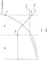
- FIG. 5illustrates a time based relationship of current, power, and measured tissue impedance graph of an exemplary bipolar output produced by an electrosurgical wave generator according to an example bipolar mode of the present disclosure
- FIG. 6illustrates a schematic diagram of an implementation of a circuit for a wave generator usable with the electrosurgical system of FIG. 1 ;
- FIG. 7illustrates an example vessel sealing instrument.
- the present disclosurerelates generally to electrosurgical systems. More specifically, the present disclosure relates to electrosurgical generators that can be relatively small, portable, and/or provide unique radio frequency electrical energy output.
- FIG. 1illustrates an exemplary system that can include some or all of the features of the present disclosure.
- an electrosurgical system 100is illustrated, which includes a wave generator 102 , a first or monopolar electrosurgical instrument 104 , a second or bipolar electrosurgical instrument 106 , and a return electrode 108 .
- the wave generator 102in one embodiment, is an RF wave generator.
- the first electrosurgical instrument 104is illustrated as a hand-held electrosurgical pencil having an electrode tip 110 associated therewith.
- the second electrosurgical instrument 106is illustrated as a pair of bipolar forceps with tips 112 , 114 . A surgeon may use either of the instruments 104 , 106 in connection with the wave generator 102 during surgical procedures.
- the wave generator 102can generate an RF electrical energy wave that can be used to cut tissue and/or cauterize blood vessels during electrosurgery.
- a surgeonmay elect to use a monopolar instrument, such as instrument 104 , along with a return electrode, such as return electrode 108 , or may elect to use a bipolar instrument, such as instrument 106 .
- electrical energy waves produced by the wave generator 102can be delivered to patient tissue via the selected instrument and the circuit is completed for energy to return to the wave generator either via the selected instrument or a separate return electrode.
- the electrical energy wavecan power the instrument 104 and be transmitted from the wave generator 102 to the instrument 104 via a cord 116 .
- An electrical dischargeis delivered from the electrode tip 110 to the patient in order to cause the heating of cellular matter of the patient tissue that is in close contact to the electrode tip 110 .
- the flow of radio frequency energy from the instrument 104 to the tissueresults in heating of the tissue in a way that accomplishes cutting and/or coagulation as desired by the surgeon.
- the return electrode 108can be electrically coupled to the wave generator 102 in order to complete the circuit and provide a return electrical path to the wave generator 102 for energy that passes into the patient's body.
- the electrical energy wavecan be transmitted from the wave generator 102 to the instrument 106 via a cord 118 .
- An electrical dischargeis delivered from one of the tips 112 , 114 to the patient tissue and returned to the wave generator 102 via the other tip 112 , 114 . Since the electrical charge is returned to the wave generator 102 via one of the tips 112 , 114 , there may be no need for a separate return electrode, such as return electrode 108 , when the instrument 106 is used.
- the wave generator 102may include electrical connections that allow for connection(s) to be made to either (i) a monopolar instrument (e.g., instrument 104 ) and a separate return electrode (e.g., return electrode 108 ), or (ii) a bipolar instrument (e.g., instrument 106 ) without a separate return electrode.
- the wave generator 102includes an electrical connection 120 for a connector 126 associated with the instrument 104 , an electrical connection 122 for a connector 128 associated with the instrument 106 , and an electrical connection 124 for a connector 130 associated with the return electrode 108 .
- the relative position, orientation, or other features of the electrical connections 120 , 122 , 124may guide a user in determining whether a return electrode (e.g., return electrode 108 ) should be used with the selected type of instrument (e.g., instruments 104 , 106 ).
- the electrical connections 120 , 122may be positioned relative to one another and/or relative to the electrical connection 124 so that only one of the connectors 126 , 128 may be connected to the wave generator 102 at a time and/or so as to either cover/block access to or leave uncovered/accessible one or more of the electrical connections 120 , 122 , 124 .
- the electrical connection 120includes three sockets that can receive the three prongs of the connector 126 associated with the instrument 104 .
- the illustrated electrical connection 122includes two sockets that can receive the two prongs of the connector 128 associated with the instrument 106 .
- the number of sockets and prongsmay vary from one embodiment to another.
- the electrical connector 120 and the connector 126may have fewer or more than three sockets and prongs, respectively.
- the electrical connector 122 and the connector 128may have fewer or more than two sockets and prongs, respectively.
- the electrical connections 120 , 122may optionally share a socket. Having the electrical connections 120 , 122 share a socket may prevent both instruments 104 , 106 from being electrically connected to the wave generator 102 at the same time. That is, for instance, when the instrument 104 is connected to the electrical connection 120 , the instrument 106 may not be able to connect to the electrical connection 122 , and vice versa. More specifically, because one of the prongs from the connector 126 is already inserted into the shared socket, one of the prongs from the connector 128 may not be inserted into the shared socket, and vice versa.
- the relative positioning of the electrical connections 120 , 122 , 124may also dictate which combination of instruments 104 , 106 and return electrode 108 can be connected to the wave generator 102 at the same time.
- the electrical connections 120 , 124may be positioned or oriented to enable both the instrument 104 and the return electrode 108 to be connected to the wave generator 102 at the same time, while also blocking access to or otherwise preventing the instrument 106 from being connected to the wave generator 102 via the electrical connection 122 .
- the electrical connections 120 , 124are spaced apart from one another so that the connector 126 associated with the instrument 104 can be connected to the electrical connection 120 and the connector 130 associated with the return electrode 108 can be connected to the electrical connection 124 at the same time.
- the instrument 106cannot be connected to the electrical connection 122 when the instrument 104 is connected to the electrical connection 120 .
- the placement of the electrical connection 124 between the sockets of the electrical connection 122can also prevent the instrument 106 and the return electrode 108 from being connected to the wave generator 102 at the same time. For instance, when the connector 128 associated with the instrument 106 is connected to the electrical connection 122 (which spans the electrical connection 124 ), the connector 130 associated with the return electrode 108 cannot be connected to the electrical connection 124 because the connector 126 is covering or otherwise blocking access to the electrical connection 124 . Similarly, when the connector 130 associated with the return electrode 108 is connected to the electrical connection 124 , the connector 128 associated with the instrument 106 cannot be connected to the electrical connection 122 because the connector 130 is blocking access to the electrical connection 122 .
- the electrical connections 120 , 122 , 124 of the wave generator 102may have or create a cross connection configuration that allows for the instrument 104 (or other monopolar instrument) and the return electrode 108 to be connected to the wave generator 102 at the same time, while also preventing the instrument 106 (or other bipolar instrument) from being connected to the wave generator 102 .
- the cross connection configurationcan also allow for the instrument 106 (or other bipolar instrument) to be connected to the wave generator 102 , while also preventing one or both of the instrument 104 (or other monopolar instrument) and the return electrode 108 from being connected to the wave generator 102 at the same time as the instrument 106 .
- the wave generator 102may be designed to be highly portable so that it can be readily moved and used in a variety of locations and settings. For instance, rather than being limited to operating room type settings as with traditional electrosurgical generators, the wave generator 102 can be highly portable for use in non-traditional settings.
- the wave generator 102may be designed for use by military personnel, first responders, veterinarians, and the like, in situations that are substantially different than operating room type settings (e.g., war zones, natural disaster areas, zoos, outdoors, etc.).
- the wave generator 102may include various characteristics and features that distinguish it from traditional electrosurgical generators.
- the wave generator 102may include a battery that powers its operation rather than requiring a continuous connection to an external power source (e.g., A/C wall outlet). Powering the wave generator 102 with an incorporated battery allows the wave generator 102 to be taken to locations and used in situations where a continuous, external power source may not be available.
- the battery powered wave generator 102may be taken outdoors (e.g., at zoos, at a car accident, in the mountains, on a ranch, in a war zone, etc.) where a continuous, external power source is not be available.
- the battery powered wave generator 102may be used in locations and situation where a continuous, external power source is normally available, but due to circumstances (e.g., power outages, etc.) is not.
- the battery used to power the wave generator 102may be rechargeable.
- the wave generator 102may have a battery recharging unit incorporated therein.
- the wave generator 102may include a connector 132 that allows for the wave generator 102 , and particularly the incorporated recharging unit, to be connected to a power source (e.g., A/C wall socket), to power the recharging unit to enable the incorporated battery to be recharged.
- the wave generator 102may not include a recharging unit. Rather, the wave generator 102 may be connected to an external recharging unit (via the connector 132 or another connector) in order to recharge the incorporated battery.
- the wave generator 102may utilize certain circuit efficiencies (e.g., use the same circuit structure for multiple operation modes) and componentry (e.g., planar transformers). Such circuit efficiencies and components can limit the size and weight of the wave generator 102 , thereby making the wave generator 102 more readily portable than traditional electrosurgical generators. For instance, using a single circuit structure for multiple operation modes can eliminate the need for multiple circuit structures typically included in multi-operation mode electrosurgical generators. This efficiency in circuit structure may also have the added benefit of reducing costs and complexity.
- circuit efficienciese.g., use the same circuit structure for multiple operation modes
- componentrye.g., planar transformers
- the size and weight of the wave generator 102can be sufficiently limited so that the wave generator 102 can be readily carried in a user's hand, medical bag, ruck sack, or the like.
- the size and weight of the wave generator 102may be sufficiently limited to allow for the wave generator 102 to be worn by a user (via a shoulder strap, belt, etc.).
- the wave generator 102may include one or more attachment points 134 to which a shoulder strap may be attached or through which a user's belt may pass.
- the wave generator 102may have a length, a width, and a height, or combinations thereof that facilitate ready transport by allowing the wave generator 102 to be easily carried, warn, or fit in a relatively small container or bag.
- the wave generator 102has a length of about 6 inches, about 8 inches, or about 10 inches, or within a range between about 5 inches to about 12 inches.
- the wave generator 102may have a width of about 5 inches, about 6 inches, about 8 inches, or about 10 inches, or within a range between about 4 inches to about 12 inches.
- the wave generator 102may have a height of about 2 inches, about 2.5 inches, about 3 inches, about 5 inches, about 7 inches, or about 9 inches, or within a range between about 2 inches to about 12 inches.
- the wave generator 102may have a volume that is limited enough to facilitate ready transport thereof.
- the wave generator 102may have a volume of about 60 cubic inches, about 100 cubic inches, about 120 cubic inches, or about 150 cubic inches, or within a range of between about 50 cubic inches and about 300 cubic inches, or within a range of between 50 cubic inches and about 750 cubic inches.
- the weight of the wave generator 102can be sufficiently limited so that the wave generator 102 can be readily carried or transported without excessive effort.
- the wave generator 102may weigh about 2 pounds, about 3.5 pounds, about 5 pounds, about 7 pounds, or about 10 pounds.
- the wave generator 102may have a weight within a range between about 1 pound and about 3 pounds, between about 2 pounds and about 5 pounds, between about 3 pounds and about 7 pounds, or between about 1.5 pounds and about 6 pounds.
- the portable nature of the wave generator 102may allow for use in non-traditional settings for surgical operations, including the outdoors. Accordingly, the wave generator 102 may be weatherized and/or ruggedized to ensure the wave generator 102 is operable in various conditions.
- the shell or casing 136 of the wave generator 102may be formed of rigid and/or water resistant materials, such as plastic. Additionally, the seams of the shell 136 , the electrical connections 120 , 122 , 124 , 132 , and the like, can include seals or other mechanisms to prevent the ingress of water, fluids, dirt, dust, organisms, and the like.
- the wave generator 102can be formed of, coated with, or otherwise include antibacterial or antimicrobial materials, such as silver ions, aluminum oxide, titanium dioxide, or other catalytic particles, chemical antibacterial components, and the like. Unlike traditional electrosurgical generators that are used in sterile operating room type settings, the wave generator 102 may be used in a variety of non-sterile settings. Accordingly, antibacterial or antimicrobial materials may be used to limit or prevent bacteria or microbes from entering, contaminating, or growing on the wave generator 102 .
- the wave generator 102may include a power switch 138 that can be used to turn the wave generator 102 on and off.
- a power switch 138that can be used to turn the wave generator 102 on and off.
- battery lifemay be preserved and inadvertent activation of a connected instrument (e.g., instruments 104 , 106 ) may not result in injury.
- the wave generator 102may be turned on and/or activated by electrically connecting an instrument (e.g., instruments 104 , 106 ) and/or a return electrode (e.g., return electrode 108 ) to one or more of the electrical connections 120 , 122 , 124 .
- an instrumente.g., instruments 104 , 106
- a return electrodee.g., return electrode 108
- connecting the connector 128 of instrument 106 to electrical connection 122may turn on or activate the wave generator 102 .
- connecting the connector 126 of instrument 104 to electrical connection 120may turn on or activate the wave generator 102 .
- the wave generator 102may also require a return electrode (e.g., return electrode 108 ) to be connected to the wave generator 102 before the wave generator 102 will turn on or be activated. Requiring a monopolar instrument and a return electrode to be connected before the wave generator 102 turns on or is activated may help to ensure that a user does not attempt to use a monopolar electrosurgical instrument without a return electrode.
- a return electrodee.g., return electrode 108
- the wave generator 102may also be equipped with a sleep mode.
- the sleep modemay be used/activated when the wave generator 102 is turned on (e.g., either via power switch 138 or connection of an instrument ( 104 , 106 )) but has not been used for a predetermined amount of time. For instance, if the wave generator 102 has been turned on, but a connected instrument (e.g., instruments 104 , 106 ) has not been activated in more than the last given period of time (e.g., the last about 2 minutes, about 5 minutes, about 10 minutes), the wave generator 102 may (automatically) enter a sleep mode. In the sleep mode, some or all of the electrical components may be deactivated.
- the wave generator 102may wake from the sleep mode simply upon activation of a connected instrument (e.g., instruments 104 , 106 ). For instance, if the wave generator 102 has entered the sleep mode as a result of non-use for a given period of time, a user may simply activate a connected instrument (e.g., instrument 104 , 106 ) in order to wake the wave generator 102 from the sleep mode. As a result, the user does not have to use the power switch 138 or disconnect and reconnect the instrument in order to turn on/activate the wave generator 102 . Thus, a user may not even know that the wave generator 102 was in a sleep mode.
- a connected instrumente.g., instruments 104 , 106
- the wave generator 102may track certain information about the use thereof. By way of example, the wave generator 102 may track the total amount of time the wave generator 102 has been used/activated since the last complete or partial battery charge. Similarly, the wave generator 102 may track the amount of time the wave generator 102 has been used/activated for a particular procedure. The wave generator 102 may also track output parameters (e.g., voltage, current, power, etc.) for a given period of time or procedure.
- output parameterse.g., voltage, current, power, etc.
- the wave generator 102may provide indicators to a user about the use and/or status thereof.
- the wave generator 102may include a battery indicator 140 that communicates the condition of the internal battery (e.g., level of charge used/remaining, etc.).
- the battery indicator 140may be a pictorial or digitally visible indicator or may be an audible indicator.
- the battery indicator 140may provide a warning to the user when the battery is running low. For instance, the battery indicator 140 may flash or make an audible sound to indicate that the battery needs to be recharged or the wave generator 102 needs to be plugged in.
- the wave generator 102may also have various mode indicators 142 that identify which mode (e.g., cut, coagulation, bipolar) the wave generator 102 is operating in.
- the mode indicators 142may also indicate an output level within the operational mode. For instance, the mode indicators 142 may indicate that the wave generator 102 is operating in a cutting mode as well as whether the wave generator 102 is operating in a “low,” “medium,” or “high” cutting mode.
- the wave generator 102may provide visual or audible indicators regarding the use thereof. For instance, when performing certain types of procedures, the wave generator 102 may provide a visual or audible indication that the procedure has been started and/or is complete. By way of example, in connection with an auto start and/or auto stop feature (discussed elsewhere herein), the wave generator 102 may provide a visual or audible indication that the procedure (or generator output) has started and/or stopped. Such a visual or audible indication may indicate to the user, among other things, that the instrument (e.g., instruments 104 , 106 ) is actively applying electrical energy to tissue, that the instrument has been or may be deactivated, or that the procedure may proceed to another step.
- the instrumente.g., instruments 104 , 106
- the wave generator 102may include an incorporated return electrode.
- a portion of the bottom surface of the wave generator 102forms or has incorporated therein a return electrode 144 .
- the return electrode 144may be a capacitive return electrode that capacitively couples a conductive element with the patient's tissue.
- the return electrode 144may be a resistive or conductive return electrode.
- the return electrode 144may be electrically connected to the internal circuitry of the wave generator 102 such that electrical energy applied to a patient's tissue with a monopolar instrument (e.g., instrument 104 ) may be returned to the wave generator 102 via the return electrode 144 .
- the wave generator 102may be set on or strapped to a patient during an electrosurgical procedure so that the incorporated return electrode 144 may make sufficient contact with the patient to enable electrosurgery to be safely performed.
- the incorporated return electrode 144may be washable, sanitizable, and/or sterilizable such that the return electrode 144 may be reused.
- the wave generator 102may be a disposable unit such that the return electrode 144 does not need to be washable, sanitizable, and/or sterilizable.
- Some of the other structural features described hereinmay also enable the wave generator 102 to be a disposable or one-time use unit. For instance, the size, circuit efficiencies, and the like, as well as the relatively minimal cost associated therewith, may allow the wave generator 102 to be disposable.
- the wave generator 102may also include hardware and/or software components that allow for data communication between the wave generator 102 and a separate computing device.
- the wave generator 102may include a communications port that enables a hardwire connection between the wave generator 102 and the separate computing device.
- the wave generator 102may include a wireless transceiver (Bluetooth, cellular, etc.) that enables wireless communication between the wave generator 102 and the separate computing device.
- datamay be communicated between the wave generator 102 and the separate computing device.
- Such data communicationmay include maintenance of or software updates for the wave generator 102 .
- the data communicationmay also include uploading of data from the wave generator 102 to the separate computing device.
- the uploaded datamay include information about the use history of the wave generator 102 , and the like.
- the data communicationmay allow for the separate computing device to control the settings or customize the modes, settings, and/or programs of the wave generator 102 . Allowing for the remote control of the wave generator 102 may be useful for a variety of reasons and in various circumstances. By way of example, in a military setting with an in the field medic that has some, but not extensive medical training, a remotely located doctor could control the settings of the wave generator 102 via a separate computing device while providing guidance to the medic via radio or telephone communication on how to perform the surgical procedure.
- the wave generator 102can include an electrosurgical cutting mode that is configured to utilize pulse width modulation (PWM) at the output.
- PWMpulse width modulation
- the wave generator 102can utilize PWM to generate a constant voltage peak level at a working surface of an associated electrode tip (e.g., a cutting or knife edge of the electrode tip 110 ), while varying the pulse width to achieve the desired cutting characteristics.
- the cutting modecan comprise amplitude control without PWM to control the power and voltage at the working surface of the associated electrode tip.
- the wave generator 102can determine the impedance of tissue that is being cut. Upon determining that a high impedance tissue (e.g., fibrous tissue) has been reached, the wave generator 102 can increase the duty cycle of the PWM signal. Increasing the duty cycle may cause the power to be applied to the working surface of the electrode tip for a longer period of time. The increased duration of the applied voltage, or power, to the working surface of the electrode tip can increase the cutting ability of the electrode tip. In contrast, when cutting through low impedance tissue, the wave generator 102 can utilize a lower duty cycle that uses less power and applies less heat to tissue.
- a high impedance tissuee.g., fibrous tissue
- FIG. 4depicts a voltage-over-time graph of an exemplary PWM output at a working surface of an electrode tip as produced by the wave generator 102 in one embodiment of the present disclosure.
- the working surfacemay be cutting through a low impedance tissue.
- the wave generator 102in response to the low impedance tissue, the wave generator 102 can utilize a low duty cycle.
- the wave generator 102may detect a high impedance tissue.
- the wave generator 102can increase the duty cycle.
- the voltages during time period 152may comprise substantially the same voltage levels as the pulses during time period 150 .
- the wave generator 102may detect a low impedance tissue and return to a duty cycle similar to that of time period 150 .
- embodiments of the present disclosuremay increase cutting ability through high impedance tissues by increasing the relative amount of time that a voltage is applied to the tissue. Additionally, at least one embodiment of the present disclosure changes the duty cycle of voltage pulses at the working surface, without substantially changing the voltage of the pulses. Accordingly, embodiments of the present disclosure can automatically adapt to different cutting needs without increasing the voltage.
- the graph depicted in FIG. 4is merely exemplary and that the voltages, pulse shapes, and frequencies are depicted for the purposes of clarity and discussion and do not necessary reflect actual outputs.
- the wave generator 102may operate at a frequency of 530 KHz.
- the generally square pulsesmay comprise rounded edges.
- pulse shapes other than generally square pulsesmay be used.
- Typical wave generatorsuse sinusoidal waves that can be amplitude modulated in order to adjust output signals.
- the wave generator 102can employ generally square waves that can be pulse width modulated to adjust the output signals.
- the wave generator 102may also use sinusoidal waves that can be amplitude adjusted, similar to typical generators.
- the generally square waves used by wave generator 102may also be amplitude modulated to adjust the output signals.
- the circuitry of the wave generator 102may have the flexibility to use either sinusoidal wave or generally square waves, which may be amplitude modulated or pulse width modulated.
- the wave generator 102may comprise various pre-defined power levels to meet the particular needs of a given surgery.
- the various power levels(e.g., low, medium, high) may each be associated with a particular power level and/or voltage.
- a low settingmay be associated with about 10 watts output, medium with about 30 watts output, and high with about 40 watts output.
- each higher settingcan respectively increase the voltage of the PWM pulses.
- a high settingcan comprise a higher voltage than a low setting.
- Limiting the output wattage to below certain desired thresholdscan provide various benefits. For instance, if the output wattage is maintained below certain thresholds (e.g., below about 49 or 50 watts), contact quality monitoring systems may not be needed. Contact quality monitoring systems are typically used to ensure that there is sufficient contact between a patient and a return electrode. Insufficient contact can result in a patient burn when using typical higher output wattage electrosurgical generators. In contrast, when the output wattage is limited, the risk for a patient burn is reduced or eliminated, thereby reducing or eliminating the need for contact quality monitoring systems.
- the power levelcan also be associated with baseline duty cycles of the PWM pulses.
- the low settingmay be associated with a fifteen percent duty cycle
- the medium settingmay be associated with a thirty percent duty cycle
- the high settingmay be associated with a fifty percent duty cycle.
- the baseline duty cyclesmay bias the PWM such that the low level setting increases its duty cycle slower than the high level setting.
- the low level duty cyclemay be biased to maintain a high duty cycle for a shorter time than the medium setting or high setting would maintain the same duty cycle.
- the wave generator 102can also or alternatively include a bipolar mode that is configured to apply constant current to an output.
- the bipolar modecan operate by outputting a particular current and monitoring a detected impedance at the output to determine whether a procedure is complete.
- the bipolar modecan deactivate or otherwise indicate that the procedure is complete.
- the wave generator 102may provide an auto start and/or auto stop feature.
- the wave generator 102may apply a desired output (e.g., constant current) once an instrument (e.g., instrument 106 ) has been activated and touched to patient tissue.
- the wave generator 102may change or discontinue the output after a specified time period or upon a change in conditions. For instance, the wave generator 102 may change or discontinue the output upon a predetermined change in tissue impedance, voltage, power, or the like.
- the bipolar modecan comprise various setting levels that indicate a desired power level at the output (e.g., 25 watts or 50 watts).
- the output of a bipolar modeis controlled such that the wave generator 102 attempts to maintain a constant current output or constant power output.
- the wave generator 102can maintain the desired output current or power through amplitude modulation of the voltage.
- the wave generator 102can maintain the desired output current or power through pulse width modulation of the output signal or generally square waveform.
- FIG. 5depicts a time based relationship of current, power, and measured tissue impedance of an exemplary bipolar procedure.
- the bipolar modeinitially outputs a generally constant current over an initial time period and impedance range 160 .
- the impedance of the tissueincreases, resulting in an increase in power as current remains constant.
- time period 162the output is changed to a generally constant power output, which may eventually lead to a rapid decrease in current (as illustrated between 164 to 166 ) in order to maintain the power level as the tissue impedance increases.
- the rapid decrease in current within region 162leads to the detection of a threshold impedance 167 , which can indicate the completion of the procedure.
- the threshold impedancemay be about 100 ohms. In other embodiments, the threshold impedance may be in a range from between about 50 ohms to about 300 ohms, or in a range from between about 50 ohms to about 1000 ohms.
- the threshold impedancemay vary based on certain factors. For instance, the type of tissue or the amount of tissue (e.g., grasped between bipolar forceps) to which the current is applied may affect the threshold impedance value, as well as the amount of time the energy is applied to the tissue.
- a small amount of tissuemay start with a relatively high impedance compared to a larger amount of tissue, and the impedance of the small amount of tissue may increase more rapidly (compared to a large amount of tissue) to a relative high or threshold impedance level.
- a large amount of tissuemay start with a relatively low impedance (compared to a small amount of tissue), and the impedance level of the large amount of tissue may increase more slowly (compared to a small amount of tissue) to a relatively high or threshold impedance level.
- the threshold impedance levelmay be lower than a threshold impedance level of a different type of tissue or a smaller amount of tissue.
- applying constant current over a time periodmay function to slowly warm tissue and cause the tissue to contract.
- conventional bipolar modesmay comprise high levels of initial current that quickly drop. The high levels of current may cause charring and other issues that can be mitigated by embodiments of the present disclosure.
- the bipolar modecan be implemented within the wave generator 102 by the same circuit used to implement the cutting mode.
- the bipolar modeoperates at a constant 50% PWM duty cycle. Accordingly, the amplitude of the voltage can be varied while maintaining a constant duty cycle. Sharing the circuit between at least these two modes may significantly reduce the cost of the wave generator 102 and, as discussed elsewhere herein, significantly shrink the size/weight of the wave generator 102 .
- the wave generator 102can include a coagulation mode that utilizes a flyback circuit for controlling the amount of power applied to the output.
- the flyback circuitcan be used to provide a constant power output without regard to the voltage applied to the output load or the impedance of the output load.
- coagulation modesare used to coagulate blood during a surgical procedure.
- Conventional coagulation systemsrely upon extremely high voltages in the range 4,000 volts peak-to-peak to achieve the desired coagulation effect. Maintaining the proper voltage and power levels and accounting for the changing impedance of the output can require significant monitoring overhead.
- the wave generator 102utilizes a flyback circuit in such a way that constant power output can be achieved without having to monitor changing voltages or impedance.
- the wave generator 102can control the amount of power being applied to the primary side of the transformer within the flyback circuit.
- the controlmay comprise amplitude modulation, current modulation, or any other form.
- the secondary side of the flyback circuitcan store the energy within the inductor and release the energy as a pulse to the load (i.e., tissue). Because the power applied to the primary side of the flyback circuit will be substantially equal to the power stored and outputted by the secondary side of the flyback circuit, a substantially constant power is applied by the wave generator 102 with a significantly higher voltage than the voltage applied to the primary side of the flyback circuit.
- the flyback circuitallows the coagulation mode to be used without requiring any monitoring of voltage applied to the tissue or impedance at the output.
- the flyback circuitensures that the proper, constant power level is applied to the tissue without regard to the voltage or impedance at the load.
- the wave generator 102may comprise a gate that functions to control pulse timing and crest factor at the output.
- the gatecan be connected to the PWM controller described above. In coagulation mode, the PWM controller may operate at a constant duty cycle.
- the gatecan further be used to determine which pulses are passed through to the output. Additionally, the gate can be used to control the crest factor of the pulses.
- crest factor adjustment in coagulation modecan be used to improve the effect and efficiency of activation for customized electrode geometries.
- An increase in the crest factormay improve the coagulation effect when using an electrode with an edge geometry that is shaped to have a working surface generally between about 0.0254 mm and about 0.1270 mm or between about 0.076 mm and about 0.1270 mm. This is in comparison to a working surface of a conventional unsharpened electrode tip (with a thickness of about 0.33 mm), which works best in coagulation mode with a lower crest factor.
- crest factorsmay range from a low crest factor value of about 5 to a high crest factor value of about 12.
- Other electrode geometriesmay have associated crest factor adjustments that can be made for effective coagulation activation.
- the wave generator 102can implement a cutting mode, a bipolar mode, and a coagulation mode all within the same circuit structure.
- the circuitmay comprise a PWM controller that can be used as described above for the cutting mode.
- the PWM controllercan be set to a constant duty cycle—such that the output is no longer PWM controlled.
- FIG. 6depicts a schematic diagram of an implementation of a circuit for a battery-powered, portable electrosurgical wave generator (e.g., wave generator 102 ).
- the schematicdepicts a microcontroller 170 in communication with various components and modules within the wave generator.
- the various input/output ports 172( a - f ) are all in communication with the same microcontroller 170 and the same power sources 174 ( a - b ).
- a planar transformer 176can be utilized to feed at least a portion of the outputs 172 ( c - f ).
- the planar transformer 176may comprise multiple taps 172 ( c - f ) that each feed a particular output.
- an input to the planar transformer 176may be in communication with a flyback circuit 178 , described above with respect to the coagulation mode.
- the components and methods described hereincan be implemented using any combination of analog or digital modules.
- the wave generator 102can be controlled using digital processing.
- the wave generator 102can be completely analog.
- the performance capabilities (e.g., cutting, coagulation, and bipolar modes) of the wave generator 102may be suited for or useful with particular types of electrosurgical instruments.
- the cutting mode described hereinmay be particularly suited for use with or provide enhanced cutting performance when used with an electrode tip that has a shaped, tapered, or sharpened working surface (referred to hereinafter as a “shaped working surface”).
- a shaped working surfaceconcentrates the electrical energy transferred from the electrode tip to the patient's tissue. The concentrated electrical energy reduces the amount of extraneous charge loss into surrounding tissue, thereby reducing the amount of necrotic damage in the tissue surrounding the incision site.
- the electrode tip 110may include a shaped working surface 168 that can facilitate efficient and concentrated transfer of the electrical energy to the patient tissue.
- chargetends to accumulate at locations where the curvature of the surface is greatest; that is, at sharp or tapered points or edges.
- the working surface 168 of the electrode tip 110By shaping or sharpening the working surface 168 of the electrode tip 110 , the charge is concentrated along a much smaller surface area or region. As a result, the electrical energy is focused into a tighter arrangement, which reduces extraneous charge loss in tissue that is not in close proximity to the shaped working surface 168 .
- the shaped working surface 168 of the electrode tip 110does need not to be sharply pointed; it need only be shaped (sharpened) to concentrate energy transfer to the degree desired for optimum cutting. For instance, the efficacious characteristics may begin to be significantly observed when the dimension (i.e., width) of the shaped working surface 168 is generally between about 0.0254 mm and about 0.1270 mm or between about 0.076 mm and about 0.1270 mm. In some embodiments, the shaped working surface 168 may have a dimension of about 0.0254 mm, about 0.076 mm, about 0.01016 mm, or about 0.1270 mm.
- a conventional unsharpened electrode tiphas a working surface thickness of about 0.33 mm and in a typical cutting mode may utilize a power setting nearing 50 watts.
- an electrode tip with a shaped working surface 168may quickly cut through tissue at less than 20 watts, a power setting of 50% less than that required for typical unsharpened electrode tips.
- a shaped working surface 168may also allow for the PWM cutting mode described herein to use shorter duty cycles than a typical unsharpened electrode tip to cut through similar tissue. Additionally, electrode tips with a shaped working surface 168 may also cut more rapidly with less resistance, less eschar production, less thermal necrosis, and improved operator control.
- Power requirements for shaped electrodes when compared with conventional electrodesmay differ considerably when PWM is employed.
- the depth of tissue cut, the type of tissue, the length of the electrode, electrode shape, and other factorsmay affect the power requirement.
- Typical power reduction for shaped electrodes vs. conventional electrodesmay be in the range of about 40% to 60%. Depending on depth of cut, tissue type, incision location, electrode length and shape, etc., the power reduction range may be from about 10% to 90%.
- the size and/or other configuration of the electrode tip 110 in combination with the PWM cutting mode described hereinmay facilitate the performance of procedures in which a high level of precision is desired.
- the electrode tip 110includes (i) one or more major surfaces (e.g., a first major surface and a second major surface opposite the first major surface); (ii) one or more longitudinal side edges (e.g., disposed at least partially between the first major surface and the second major surface); and/or (iii) a cross-sectional area (e.g., disposed at least partially between the first major surface and/or the second major surface and/or the one or more longitudinal side edges).
- the thickness of the longitudinal side edge(s)can be greater than about 0.01 inches (0.254 mm).
- the longitudinal side edgecan form or include two or more longitudinal cutting edges, and/or the body can comprise a cross-sectional area-to-number of longitudinal cutting edges ratio that is less than or equal to about 0.0004 square inches per longitudinal cutting edge (in 2 /E).
- the longitudinal side edge(s)can have a thickness that is less than or equal to about 0.01 inches.
- the longitudinal side edgecan form or include one longitudinal cutting edge, and/or the body can comprise a cross-sectional area-to-number of longitudinal cutting edges ratio that is less than or equal to about 0.000150 square inches per longitudinal cutting edge (in 2 /E).
- the electrode tip 110can include one or more longitudinal side edges that have a thickness that is less than or equal to about 0.01 inches (each comprising one longitudinal cutting edge) and one or more longitudinal side edges that have a thickness that is greater than about 0.01 inches (each comprising two or more longitudinal cutting edges).
- the body of the electrodecan comprise a cross-sectional area-to-number of longitudinal cutting edges ratio that is less than or equal to about 0.001 square inches per longitudinal cutting edge (in 2 /E).
- a vessel sealing instrumentis another type of electrosurgical instrument that may be particularly suited for use in combination with the wave generator 102 .
- FIG. 7illustrates an example vessel sealing instrument 180 that may be used in conjunction with the wave generator 102 .
- the vessel sealing instrument 180includes a handle 182 , an elongated shaft 184 extending from the handle 182 , and a pair of jaws 186 , 188 at the opposing end of the elongated shaft 184 .
- the vessel sealing instrument 180also includes an input 190 for receiving/returning electrical energy from an electrosurgical wave generator (e.g., wave generator 102 ) via a wire or other electrical conductor.
- the electrical energymay be used to, among other things, seal vessels or cut tissue that is between the jaws 186 , 188 .
- the handle 182may be designed such that squeezing a lever portion of the handle 182 toward another part of the handle 182 activates one or both of the jaws 186 , 188 . This activation may lower the jaw 186 onto or towards the jaw 188 , or vice versa. Additionally or alternatively, squeezing the lever of the handle 182 may initiate the flow of electrical energy to one or both of the jaws 186 , 188 .
- the handle 182(or another part of the instrument 180 ) may include a separate switch or button that initiates the flow of electrical energy to one or both of the jaws 186 , 188 .
- a switch mechanismsuch as a foot switch, may be used to initiate the flow of electrical energy to one or both of the jaws 186 , 188 .
- a vessel sealing instrumentmay be particularly useful when used in conjunction with the coagulation or bipolar modes described herein.
- a usermay use the vessel sealing instrument 180 to grasp a blood vessel between the jaws 186 , 188 .
- the coagulation or bipolar modemay then be used to communicate electrical energy to the grasped blood vessel in order to heat the blood vessel. Heating of the blood vessel results in the denaturing of the collagen and elastin found in the blood vessel walls.
- the flow of electrical energy to the jaws 186 , 188(and thus to the blood vessel) is turned off, allowing the blood vessel to begin cooling.
- the jaws 186 , 188may act as a clamp to hold the opposing sides of the blood vessel wall together.
- the clamping forcemay be applied and/or maintained manually by moving and/or holding the lever portion of the handle 182 .
- the vessel sealing instrument 180may include a mechanical or electro-mechanical mechanism that maintains the clamping force until the vessel sealing procedure is completed.
- the mechanical or electro-mechanical mechanismmay be configured to release the clamping force after a predetermined period of time (e.g., 5 seconds, 10 seconds, 15 seconds, 30 seconds), upon a user input (moving the lever portion of the handle 182 ), or in response an electrical signal (e.g., from the wave generator 102 ).
Landscapes
- Health & Medical Sciences (AREA)
- Surgery (AREA)
- Life Sciences & Earth Sciences (AREA)
- Engineering & Computer Science (AREA)
- Molecular Biology (AREA)
- Animal Behavior & Ethology (AREA)
- Veterinary Medicine (AREA)
- Biomedical Technology (AREA)
- Heart & Thoracic Surgery (AREA)
- Medical Informatics (AREA)
- Nuclear Medicine, Radiotherapy & Molecular Imaging (AREA)
- Public Health (AREA)
- General Health & Medical Sciences (AREA)
- Physics & Mathematics (AREA)
- Plasma & Fusion (AREA)
- Otolaryngology (AREA)
- Pathology (AREA)
- Oral & Maxillofacial Surgery (AREA)
- Surgical Instruments (AREA)
- Charge And Discharge Circuits For Batteries Or The Like (AREA)
Abstract
Description
Claims (32)
Priority Applications (13)
| Application Number | Priority Date | Filing Date | Title |
|---|---|---|---|
| US15/213,163US11446078B2 (en) | 2015-07-20 | 2016-07-18 | Electrosurgical wave generator |
| EP16828419.8AEP3324869A4 (en) | 2015-07-20 | 2016-07-19 | ELECTROSURGICAL WAVE GENERATOR |
| CA2993172ACA2993172A1 (en) | 2015-07-20 | 2016-07-19 | Electrosurgical wave generator |
| KR1020187004629AKR20180030882A (en) | 2015-07-20 | 2016-07-19 | Electrosurgical wave generator |
| AU2016295410AAU2016295410B2 (en) | 2015-07-20 | 2016-07-19 | Electrosurgical wave generator |
| PCT/US2016/042969WO2017015287A1 (en) | 2015-07-20 | 2016-07-19 | Electrosurgical wave generator |
| MX2018000876AMX2018000876A (en) | 2015-07-20 | 2016-07-19 | Electrosurgical wave generator. |
| CN201680042759.3ACN108472069B (en) | 2015-07-20 | 2016-07-19 | Electrosurgical wave generator |
| MA042499AMA42499A (en) | 2015-07-20 | 2016-07-19 | ELECTROSURGICAL WAVE GENERATOR |
| JP2018502671AJP6821648B2 (en) | 2015-07-20 | 2016-07-19 | Wave generator for electrosurgery |
| BR112018001030-8ABR112018001030B1 (en) | 2015-07-20 | 2016-07-19 | ELECTROSURGICAL WAVE GENERATOR TO CARRY OUT ELECTRICALLY ACTIVATED MEDICAL PROCEDURES |
| IL256580AIL256580A (en) | 2015-07-20 | 2017-12-26 | Electrosurgical wave generator |
| ZA201801117AZA201801117B (en) | 2015-07-20 | 2018-02-19 | Electrosurgical wave generator |
Applications Claiming Priority (2)
| Application Number | Priority Date | Filing Date | Title |
|---|---|---|---|
| US201562194390P | 2015-07-20 | 2015-07-20 | |
| US15/213,163US11446078B2 (en) | 2015-07-20 | 2016-07-18 | Electrosurgical wave generator |
Publications (2)
| Publication Number | Publication Date |
|---|---|
| US20170020598A1 US20170020598A1 (en) | 2017-01-26 |
| US11446078B2true US11446078B2 (en) | 2022-09-20 |
Family
ID=57834561
Family Applications (1)
| Application Number | Title | Priority Date | Filing Date |
|---|---|---|---|
| US15/213,163Active2037-11-30US11446078B2 (en) | 2015-07-20 | 2016-07-18 | Electrosurgical wave generator |
Country Status (13)
| Country | Link |
|---|---|
| US (1) | US11446078B2 (en) |
| EP (1) | EP3324869A4 (en) |
| JP (1) | JP6821648B2 (en) |
| KR (1) | KR20180030882A (en) |
| CN (1) | CN108472069B (en) |
| AU (1) | AU2016295410B2 (en) |
| BR (1) | BR112018001030B1 (en) |
| CA (1) | CA2993172A1 (en) |
| IL (1) | IL256580A (en) |
| MA (1) | MA42499A (en) |
| MX (1) | MX2018000876A (en) |
| WO (1) | WO2017015287A1 (en) |
| ZA (1) | ZA201801117B (en) |
Families Citing this family (9)
| Publication number | Priority date | Publication date | Assignee | Title |
|---|---|---|---|---|
| US11052557B2 (en)* | 2016-11-04 | 2021-07-06 | Heated Blades Holding Company, Llc | Heating blades of razor using RF energy |
| IT201800009378A1 (en)* | 2018-10-11 | 2020-04-11 | Tumino Mariliana | FORCEPS FOR MEDICAL, VETERINARY OR SURGICAL USE. |
| JP7373565B2 (en)* | 2018-11-20 | 2023-11-02 | エヌユーエネルキ, インコーポレイテッド | An electrical stimulation device that applies frequency and peak voltage that are inversely proportional to each other. |
| GB2579644A (en)* | 2018-12-10 | 2020-07-01 | Creo Medical Ltd | A modular electrosurgical system, and modules for said system |
| KR20210000176A (en)* | 2019-06-24 | 2021-01-04 | 고려대학교 산학협력단 | Surgical device for incision and ligation of target tissue |
| US12201343B2 (en) | 2020-01-30 | 2025-01-21 | Gyrus Acmi, Inc. | Adaptive blend of electrosurgical cutting and coagulation |
| CN114052809B (en)* | 2020-08-04 | 2022-12-23 | 苏州英途康医疗科技有限公司 | Electric anastomat, handle low-power-consumption control method and device thereof, and storage medium |
| KR102399560B1 (en)* | 2020-10-23 | 2022-05-19 | (주)센서테크 | Variable Transformer Based Connector for Multi-Purpose Load |
| US20250099155A1 (en)* | 2022-02-03 | 2025-03-27 | Us Patent Innovations, Llc | Electrosurgical system with adaptive non-thermal plasma control |
Citations (185)
| Publication number | Priority date | Publication date | Assignee | Title |
|---|---|---|---|---|
| US3952748A (en) | 1974-07-18 | 1976-04-27 | Minnesota Mining And Manufacturing Company | Electrosurgical system providing a fulguration current |
| US4017745A (en) | 1976-02-11 | 1977-04-12 | American Laser Corporation | Switching regulator power supply |
| US4024467A (en)* | 1974-07-15 | 1977-05-17 | Sybron Corporation | Method for controlling power during electrosurgery |
| US4108181A (en) | 1977-01-28 | 1978-08-22 | Unicare Systems, Inc. | Cautery device for ophthalmic or the like surgical application |
| US4196734A (en) | 1978-02-16 | 1980-04-08 | Valleylab, Inc. | Combined electrosurgery/cautery system and method |
| US4359052A (en) | 1976-01-26 | 1982-11-16 | Concept Inc. | Removable tip cautery |
| US4473075A (en)* | 1982-12-08 | 1984-09-25 | Medical Research Associates, Ltd. | Electrosurgical generator with improved rapid start capability |
| US4563570A (en) | 1984-09-04 | 1986-01-07 | Suncoast Medical Manufacturing, Inc. | Battery powered cautery with improved protective cover arrangement |
| US4727874A (en)* | 1984-09-10 | 1988-03-01 | C. R. Bard, Inc. | Electrosurgical generator with high-frequency pulse width modulated feedback power control |
| US4878493A (en) | 1983-10-28 | 1989-11-07 | Ninetronix Venture I | Hand-held diathermy apparatus |
| US5099840A (en) | 1988-01-20 | 1992-03-31 | Goble Nigel M | Diathermy unit |
| US5163937A (en) | 1990-01-25 | 1992-11-17 | Transtech Scientific, Inc. | Waterproof body for cautery devices |
| US5167660A (en) | 1990-03-27 | 1992-12-01 | Siemens Aktiengesellschaft | Hf surgery device |
| US5169398A (en) | 1990-09-21 | 1992-12-08 | Glaros Nicholas G | Electronic hair remover |
| US5207697A (en) | 1991-06-27 | 1993-05-04 | Stryker Corporation | Battery powered surgical handpiece |
| US5318563A (en) | 1992-06-04 | 1994-06-07 | Valley Forge Scientific Corporation | Bipolar RF generator |
| US5401273A (en) | 1993-03-01 | 1995-03-28 | Shippert; Ronald D. | Cauterizing instrument for surgery |
| US5422567A (en) | 1993-12-27 | 1995-06-06 | Valleylab Inc. | High frequency power measurement |
| US5423810A (en) | 1992-02-27 | 1995-06-13 | G2 Design Limited | Cauterising apparatus |
| US5464428A (en)* | 1994-03-08 | 1995-11-07 | Physio-Control Corporation | Environmentally protected medical electronic instrument |
| US5688265A (en) | 1995-08-30 | 1997-11-18 | Aaron Medical Industries, Inc. | Battery powered cautery assembly |
| US5792138A (en)* | 1996-02-22 | 1998-08-11 | Apollo Camera, Llc | Cordless bipolar electrocautery unit with automatic power control |
| US5836943A (en) | 1996-08-23 | 1998-11-17 | Team Medical, L.L.C. | Electrosurgical generator |
| US5871481A (en) | 1997-04-11 | 1999-02-16 | Vidamed, Inc. | Tissue ablation apparatus and method |
| US5971980A (en)* | 1995-05-02 | 1999-10-26 | Heart Rhythm Technologies, Inc. | System for controlling the energy delivered to a patient for ablation |
| US5976128A (en) | 1996-06-14 | 1999-11-02 | Gebrueder Berchtold Gmbh & Co. | Electrosurgical high frequency generator |
| US6039734A (en)* | 1995-10-24 | 2000-03-21 | Gyrus Medical Limited | Electrosurgical hand-held battery-operated instrument |
| US6113596A (en)* | 1996-12-30 | 2000-09-05 | Enable Medical Corporation | Combination monopolar-bipolar electrosurgical instrument system, instrument and cable |
| US6210408B1 (en) | 1999-02-24 | 2001-04-03 | Scimed Life Systems, Inc. | Guide wire system for RF recanalization of vascular blockages |
| US6238388B1 (en)* | 1999-09-10 | 2001-05-29 | Alan G. Ellman | Low-voltage electrosurgical apparatus |
| US20010027968A1 (en) | 2000-01-31 | 2001-10-11 | Mark Stuart | Retractable cauterizing knife |
| US6325799B1 (en) | 1997-04-24 | 2001-12-04 | Gyrus Medical Limited | Electrosurgical instrument |
| US6402742B1 (en) | 1997-04-11 | 2002-06-11 | United States Surgical Corporation | Controller for thermal treatment of tissue |
| US6482200B2 (en) | 2001-01-03 | 2002-11-19 | Ronald D. Shippert | Cautery apparatus and method |
| US6520185B1 (en)* | 1999-03-17 | 2003-02-18 | Ntero Surgical, Inc. | Systems and methods for reducing post-surgical complications |
| US20030144680A1 (en) | 2002-01-22 | 2003-07-31 | Sontra Medical, Inc. | Portable ultrasonic scalpel/cautery device |
| US20030181898A1 (en) | 1999-05-28 | 2003-09-25 | Bowers William J. | RF filter for an electrosurgical generator |
| US6626901B1 (en) | 1997-03-05 | 2003-09-30 | The Trustees Of Columbia University In The City Of New York | Electrothermal instrument for sealing and joining or cutting tissue |
| US6629974B2 (en) | 2000-02-22 | 2003-10-07 | Gyrus Medical Limited | Tissue treatment method |
| US20040006337A1 (en) | 2000-05-12 | 2004-01-08 | Michael Nasab | Multi-channnel rf energy delivery with coagulum reduction |
| US20040030328A1 (en) | 2001-07-12 | 2004-02-12 | Eggers Philip E. | Electrosurgical generator |
| US20040082946A1 (en) | 2002-10-24 | 2004-04-29 | Valley Forge Scientific | Electrosurgical generator apparatus |
| US6740079B1 (en) | 2001-07-12 | 2004-05-25 | Neothermia Corporation | Electrosurgical generator |
| US20040138654A1 (en)* | 2003-01-09 | 2004-07-15 | Gyrus Medical Limited | Electrosurgical generator |
| US20050010206A1 (en) | 2000-05-12 | 2005-01-13 | Cardima, Inc. | System and method for multi-channel RF energy delivery with coagulum reduction |
| US6843789B2 (en)* | 2000-10-31 | 2005-01-18 | Gyrus Medical Limited | Electrosurgical system |
| US20050015080A1 (en) | 2003-07-16 | 2005-01-20 | Paul Ciccone | Device for cutting or heating medical implants |
| US6939347B2 (en) | 2002-11-19 | 2005-09-06 | Conmed Corporation | Electrosurgical generator and method with voltage and frequency regulated high-voltage current mode power supply |
| US20050234442A1 (en) | 1999-09-01 | 2005-10-20 | Michael Spears | Electrosurgical cutting and cauterizing device |
| US20050283148A1 (en) | 2004-06-17 | 2005-12-22 | Janssen William M | Ablation apparatus and system to limit nerve conduction |
| US20060161148A1 (en) | 2005-01-13 | 2006-07-20 | Robert Behnke | Circuit and method for controlling an electrosurgical generator using a full bridge topology |
| US20060241589A1 (en) | 2004-07-20 | 2006-10-26 | Surginetics, Llc | Battery Powered Electrosurgical System |
| US20060259034A1 (en) | 2005-05-12 | 2006-11-16 | Joseph Eder | Apparatus for Tissue Cauterization |
| US7182762B2 (en) | 2003-12-30 | 2007-02-27 | Smith & Nephew, Inc. | Electrosurgical device |
| US20070129726A1 (en) | 2005-05-12 | 2007-06-07 | Eder Joseph C | Electrocautery method and apparatus |
| US20070156137A1 (en) | 2006-01-03 | 2007-07-05 | Geisel Donald J | High efficiency, precision electrosurgical apparatus and method |
| WO2007076413A2 (en)* | 2005-12-20 | 2007-07-05 | Microban Products Company | Antimicrobial durable medical equipment |
| US20070167941A1 (en)* | 2006-01-18 | 2007-07-19 | Andrew Hamel | Electrosurgical system |
| US20070185482A1 (en) | 2005-05-12 | 2007-08-09 | Eder Joseph C | Electrocautery method and apparatus |
| US7255694B2 (en)* | 2002-12-10 | 2007-08-14 | Sherwood Services Ag | Variable output crest factor electrosurgical generator |
| US20070250057A1 (en) | 2006-03-30 | 2007-10-25 | Ethicon Endo-Surgery, Inc. | Protective needle knife |
| US20080013350A1 (en)* | 2006-07-12 | 2008-01-17 | Gregory Goliszek | Planar transformer power supply |
| US20080082095A1 (en)* | 2006-10-02 | 2008-04-03 | Shores Ronald B | Near-instantaneous responsive closed loop control electrosurgical generator and method |
| US20080119841A1 (en) | 2006-01-03 | 2008-05-22 | Geisel Donald J | High, efficiency, precision electrosurgical apparatus and method |
| US20080172052A1 (en) | 2006-05-02 | 2008-07-17 | Joseph Eder | Surgical Tool |
| US20080221565A1 (en) | 2005-05-12 | 2008-09-11 | Joseph Charles Eder | Electrocautery method and apparatus |
| US7445619B2 (en) | 2000-08-18 | 2008-11-04 | Map Technologies Llc | Devices for electrosurgery |
| US7458974B1 (en) | 2000-07-25 | 2008-12-02 | Endovascular Technologies, Inc. | Apparatus and method for electrically induced thrombosis |
| US20090069799A1 (en) | 2000-12-28 | 2009-03-12 | Senorx, Inc. | Electrosurgical medical system and method |
| US20090088811A1 (en) | 2007-09-27 | 2009-04-02 | Wulfman David R | Implantable lead with an electrostimulation capacitor |
| US20090138003A1 (en) | 2007-11-28 | 2009-05-28 | Derek Dee Deville | Cordless Medical Cauterization and Cutting Device |
| US20090138006A1 (en) | 2007-11-28 | 2009-05-28 | Bales Thomas O | Cordless power-assisted medical cauterization and cutting device |
| US20090149732A1 (en) | 2007-12-08 | 2009-06-11 | Weinstock Ronald J | System for use of electrical resonant frequencies in analyzing and treating abnormality of human and animal tissues |
| US20090171354A1 (en) | 2007-11-28 | 2009-07-02 | Derek Dee Deville | Cordless Medical Cauterization and Cutting Device |
| US20090209990A1 (en) | 2008-02-14 | 2009-08-20 | Ethicon Endo-Surgery, Inc. | Motorized surgical cutting and fastening instrument having handle based power source |
| US20090209979A1 (en) | 2008-02-14 | 2009-08-20 | Ethicon Endo-Surgery, Inc. | Motorized cutting and fastening instrument having control circuit for optimizing battery usage |
| US20090240245A1 (en) | 2008-03-19 | 2009-09-24 | Derek Dee Deville | Method for Powering a Surgical Instrument |
| US20090240246A1 (en) | 2008-03-19 | 2009-09-24 | Derek Dee Deville | Cordless Medical Cauterization and Cutting Device |
| US20090248007A1 (en) | 2008-03-31 | 2009-10-01 | Applied Medical Resources Corporation | Electrosurgical system |
| US20100030212A1 (en) | 2008-05-13 | 2010-02-04 | Aramayo Thomas F | Methods, systems, and devices for performing electrosurgical procedures |
| WO2010016259A1 (en) | 2008-08-08 | 2010-02-11 | iMed Japan株式会社 | Handy electrosurgical instrument |
| US20100076475A1 (en) | 2008-09-23 | 2010-03-25 | Ethicon-Endo Surgery, Inc. | Motorized surgical instrument |
| US20100130976A1 (en) | 2008-11-21 | 2010-05-27 | Smith & Nephew Inc. | Reducing cross-talk effects in an rf electrosurgical device |
| US7793812B2 (en) | 2008-02-14 | 2010-09-14 | Ethicon Endo-Surgery, Inc. | Disposable motor-driven loading unit for use with a surgical cutting and stapling apparatus |
| US7801585B1 (en) | 2003-06-02 | 2010-09-21 | Newlife Sciences Llc | System for analyzing and treating abnormality of human and animal tissues |
| US20100241116A1 (en) | 2009-03-17 | 2010-09-23 | Benamou Steffan A | Method and system for adjusting source impedance and maximizing output by RF generator |
| US20100268220A1 (en) | 2007-04-19 | 2010-10-21 | Miramar Labs, Inc. | Systems, Apparatus, Methods and Procedures for the Noninvasive Treatment of Tissue Using Microwave Energy |
| US7828794B2 (en) | 2005-08-25 | 2010-11-09 | Covidien Ag | Handheld electrosurgical apparatus for controlling operating room equipment |
| US20110022032A1 (en) | 2007-10-05 | 2011-01-27 | Tyco Healthcare Group Lp | Battery ejection design for a surgical device |
| US7900805B2 (en) | 2007-01-10 | 2011-03-08 | Ethicon Endo-Surgery, Inc. | Surgical instrument with enhanced battery performance |
| US20110060329A1 (en) | 2009-09-10 | 2011-03-10 | Tyco Healthcare Group Lp | System and Method for Power Supply Noise Reduction |
| US20110071520A1 (en) | 2009-09-23 | 2011-03-24 | Tyco Healthcare Group Lp | Methods and Apparatus for Smart Handset Design in Surgical Instruments |
| US20110082486A1 (en) | 2008-08-06 | 2011-04-07 | Ethicon Endo-Surgery, Inc. | Devices and techniques for cutting and coagulating tissue |
| US7922675B2 (en) | 2003-06-17 | 2011-04-12 | Seung-Young Hwang | Advanced handable skin care device and operating method thereof |
| US20110087212A1 (en) | 2009-10-09 | 2011-04-14 | Ethicon Endo-Surgery, Inc. | Surgical generator for ultrasonic and electrosurgical devices |
| US20110112530A1 (en)* | 2009-11-06 | 2011-05-12 | Keller Craig A | Battery Powered Electrosurgery |
| US20110115562A1 (en) | 2009-11-16 | 2011-05-19 | Tyco Healthcare Group Lp | Class Resonant-H Electrosurgical Generators |
| US20110172660A1 (en)* | 2010-01-12 | 2011-07-14 | Bales Jr Thomas O | Battery-Powered Electrosurgical Forceps With Multi-Turn Selectable-Ratio Transformer |
| CA2731002A1 (en) | 2010-02-05 | 2011-08-05 | Tyco Healthcare Group, Lp | Square wave for vessel sealing |
| US20110213354A1 (en) | 2010-02-26 | 2011-09-01 | Smith Robert B | Enhanced Lossless Current Sense Circuit |
| US20110278956A1 (en)* | 2010-05-11 | 2011-11-17 | Searete Llc, A Limited Liability Corporation Of The State Of Delaware | System including wearable power receiver and wearable power-output device |
| US8064988B2 (en) | 2003-06-02 | 2011-11-22 | Newlife Sciences, Llc | System for analyzing and treating abnormality of human and animal tissues |
| US20110288543A1 (en) | 2010-05-20 | 2011-11-24 | Cheng Elbert T | High frequency alternating current medical device with self-limiting conductive material and method |
| US20110288573A1 (en) | 2008-02-14 | 2011-11-24 | Ethicon Endo-Surgery, Inc. | Robotically-controlled motorized surgical cutting and fastening instrument |
| US20110295269A1 (en) | 2008-09-23 | 2011-12-01 | Ethicon Endo-Surgery, Inc. | Robotically-controlled motorized surgical instrument |
| US20110319881A1 (en)* | 2010-06-25 | 2011-12-29 | Tyco Healthcare Group Lp | Current-Fed Push-Pull Converter with Passive Voltage Clamp |
| US20120022519A1 (en) | 2010-07-22 | 2012-01-26 | Ethicon Endo-Surgery, Inc. | Surgical cutting and sealing instrument with controlled energy delivery |
| US20120071796A1 (en) | 2007-12-03 | 2012-03-22 | Smith Kevin W | Battery-Powered Hand-Held Ultrasonic Surgical Cautery Cutting Device |
| US20120071866A1 (en) | 2010-09-17 | 2012-03-22 | Ethicon Endo-Surgery, Inc. | Power control arrangements for surgical instruments and batteries |
| US20120078139A1 (en) | 2009-10-09 | 2012-03-29 | Ethicon Endo-Surgery, Inc. | Surgical generator for ultrasonic and electrosurgical devices |
| US20120116379A1 (en) | 2010-11-05 | 2012-05-10 | Yates David C | Motor Driven Electrosurgical Device With Mechanical And Electrical Feedback |
| US20120115005A1 (en) | 2010-11-05 | 2012-05-10 | Stulen Foster B | Power source management for medical device |
| US20120136347A1 (en) | 2010-10-01 | 2012-05-31 | Applied Medical Resources Corporation | Electrosurgical instruments and connections thereto |
| US8197472B2 (en) | 2005-03-25 | 2012-06-12 | Maquet Cardiovascular, Llc | Tissue welding and cutting apparatus and method |
| US20120202388A1 (en)* | 2011-02-09 | 2012-08-09 | Peter Selig | Universal connector socket |
| US20120215216A1 (en) | 2010-12-23 | 2012-08-23 | The Regents Of The University Of Colorado, A Body Corporate | Electrosurgical generator controller for regulation of electrosurgical generator output power |
| US20120265196A1 (en) | 2009-10-09 | 2012-10-18 | Ethicon Endo-Surgery, Inc. | Surgical generator for ultrasonic and electrosurgical devices |
| US20120310229A1 (en) | 2011-05-31 | 2012-12-06 | Tyco Healthcare Group Lp | Surgical Device with DC Power Connection |
| US20130018364A1 (en) | 2011-07-11 | 2013-01-17 | Tyco Healthcare Group Lp | Stand Alone Energy-Based Tissue Clips |
| US20130041371A1 (en) | 2008-02-14 | 2013-02-14 | Ethicon Endo-Surgery, Inc. | Motorized surgical cutting and fastening instrument having a magnetic drive train torque limiting device |
| US20130066311A1 (en) | 2011-09-09 | 2013-03-14 | Tyco Healthcare Group Lp | Surgical Generator And Related Method For Mitigating Overcurrent Conditions |
| US8401667B2 (en) | 2008-11-17 | 2013-03-19 | Vessix Vascular, Inc. | Selective accumulation of energy with or without knowledge of tissue topography |
| US20130067725A1 (en) | 2011-09-20 | 2013-03-21 | Vivant Medical, Inc. | Handheld Medical Devices Including Microwave Amplifier Unit At Device Handle |
| US20130072922A1 (en) | 2011-09-20 | 2013-03-21 | Vivant Medical, Inc. | Handheld Medical Devices Including Microwave Amplifier Unit At Device Handle |
| US20130072923A1 (en) | 2011-09-20 | 2013-03-21 | Vivant Medical, Inc. | Handheld Medical Devices Including Microwave Amplifier Unit At Device Handle |
| US20130072920A1 (en) | 2011-09-20 | 2013-03-21 | Vivant Medical, Inc. | Handheld Medical Devices Including Microwave Amplifier Unit At Device Handle |
| US20130072921A1 (en) | 2011-09-20 | 2013-03-21 | Vivant Medical, Inc. | Handheld Medical Devices Including Microwave Amplifier Unit At Device Handle |
| US8406894B2 (en) | 2007-12-12 | 2013-03-26 | Miramar Labs, Inc. | Systems, apparatus, methods and procedures for the noninvasive treatment of tissue using microwave energy |
| US20130103023A1 (en) | 2011-10-24 | 2013-04-25 | Ethicon Endo-Surgery, Inc. | Litz wire battery powered device |
| US8439939B2 (en) | 2007-12-03 | 2013-05-14 | Covidien Ag | Method of powering a surgical instrument |
| US20130126581A1 (en) | 2008-09-23 | 2013-05-23 | Ethicon Endo-Surgery, Inc. | Motorized surgical instrument |
| US8486058B1 (en)* | 2009-01-30 | 2013-07-16 | Chest Innovations, Inc. | Minigenerator |
| US20130204243A1 (en) | 2012-02-02 | 2013-08-08 | John Jordan Newkirk | Handheld electrosurgical generator |
| US20130282003A1 (en) | 2012-04-09 | 2013-10-24 | Ethicon Endo-Surgery, Inc. | Devices and techniques for cutting and coagulating tissue |
| US20140005652A1 (en) | 2008-02-14 | 2014-01-02 | Ethicon Endo-Surgery, Inc. | Motorized surgical cutting and fastening instrument |
| US20140018795A1 (en) | 2010-11-08 | 2014-01-16 | Bovie Medical Corporation | Multi-button electrosurgical apparatus |
| US8652120B2 (en) | 2007-01-10 | 2014-02-18 | Ethicon Endo-Surgery, Inc. | Surgical instrument with wireless communication between control unit and sensor transponders |
| US8663262B2 (en) | 2007-12-03 | 2014-03-04 | Covidien Ag | Battery assembly for battery-powered surgical instruments |
| US8664934B2 (en) | 2012-01-27 | 2014-03-04 | Covidien Lp | System and method for verifying the operating frequency of digital control circuitry |
| US20140081256A1 (en) | 2012-09-12 | 2014-03-20 | Electromedical Associates Llc | Portable electrosurgical instruments and method of using same |
| US20140104028A1 (en) | 2012-10-17 | 2014-04-17 | Covidien Lp | Planar transformers having reduced termination losses |
| US20140128864A1 (en)* | 2012-11-08 | 2014-05-08 | Gyrus Medical Limited | Electrosurgical generator |
| US20140148799A1 (en) | 2012-11-27 | 2014-05-29 | Covidien Lp | Surgical instruments |
| US8752749B2 (en) | 2008-02-14 | 2014-06-17 | Ethicon Endo-Surgery, Inc. | Robotically-controlled disposable motor-driven loading unit |
| US8764747B2 (en) | 2010-06-10 | 2014-07-01 | Ethicon Endo-Surgery, Inc. | Electrosurgical instrument comprising sequentially activated electrodes |
| US20140188101A1 (en) | 2008-11-13 | 2014-07-03 | Covidien Ag | Radio Frequency Generator and Method for a Cordless Medical Cauterization and Cutting Device |
| US20140207124A1 (en) | 2013-01-23 | 2014-07-24 | Ethicon Endo-Surgery, Inc. | Surgical instrument with selectable integral or external power source |
| US20140214136A1 (en) | 2013-01-30 | 2014-07-31 | Tria Beauty, Inc. | Pulse Width Modulation Control for Battery-Powered Laser Device |
| US20140254221A1 (en) | 2013-03-11 | 2014-09-11 | Covidien Lp | Constant power inverter with crest factor control |
| US20140276768A1 (en) | 2013-03-14 | 2014-09-18 | Ellman International, Inc. | Electrosurgical systems |
| US20140276754A1 (en) | 2013-03-15 | 2014-09-18 | Covidien Lp | System and method for power control of electrosurgical resonant inverters |
| US20140276750A1 (en) | 2013-03-15 | 2014-09-18 | Covidien Lp | Systems and methods for narrowband real impedance control in electrosurgery |
| US8840603B2 (en) | 2007-01-10 | 2014-09-23 | Ethicon Endo-Surgery, Inc. | Surgical instrument with wireless communication between control unit and sensor transponders |
| US8847639B1 (en) | 2013-12-27 | 2014-09-30 | Freescale Semiconductor, Inc. | Waveform generator |
| US20140303612A1 (en) | 2013-04-03 | 2014-10-09 | Gyrus Medical Limited | Electrosurgical system |
| WO2014181077A1 (en) | 2013-05-08 | 2014-11-13 | Creo Medical Limited | Method and apparatus for controlling power delivered by electrosurgical probe |
| WO2014181078A1 (en) | 2013-05-08 | 2014-11-13 | Creo Medical Limited | Electrosurgical apparatus having rf pulse profile controller |
| US20140358138A1 (en) | 2013-05-31 | 2014-12-04 | Covidien Lp | Gain compensation for a full bridge inverter |
| US20140364844A1 (en) | 2013-06-06 | 2014-12-11 | Electromedical Associates Llc | Miniaturized dual-mode electrosurgical device and methods of using same |
| US20140376269A1 (en) | 2013-06-24 | 2014-12-25 | Covidien Lp | Dead-time optimization of resonant inverters |
| WO2014210136A1 (en) | 2013-06-25 | 2014-12-31 | Spears Michael | System, method and apparatus for performing electrosurgery through the use of radiating energy |
| US20150005760A1 (en) | 2011-12-23 | 2015-01-01 | Lina Medical Aps | Pulse generator |
| US20150025523A1 (en) | 2013-07-16 | 2015-01-22 | Covidien Lp | Electrosurgical generator with continuously and arbitrarily variable crest factor |
| US20150025521A1 (en) | 2013-07-19 | 2015-01-22 | Covidien Lp | Electrosurgical generators |
| US20150032096A1 (en) | 2013-07-24 | 2015-01-29 | Covidien Lp | Systems and methods for generating electrosurgical energy using a multistage power converter |
| US20150066022A1 (en) | 2013-08-30 | 2015-03-05 | Ethicon Endo-Surgery, Inc. | Surgical devices with close quarter articulation features |
| US20150088129A1 (en) | 2008-09-27 | 2015-03-26 | Witricity Corporation | Wireless Energy Transfer for Medical Applications |
| US20150088125A1 (en) | 2013-09-26 | 2015-03-26 | Covidien Lp | Systems and methods for estimating tissue parameters using surgical devices |
| US20150088117A1 (en) | 2013-09-24 | 2015-03-26 | Covidien Lp | Systems and methods for improving efficiency of electrosurgical generators |
| US20150088118A1 (en) | 2013-09-24 | 2015-03-26 | Covidien Lp | Systems and methods for improving efficiency of electrosurgical generators |
| US20150088116A1 (en) | 2013-09-26 | 2015-03-26 | Covidien Lp | Systems and methods for estimating tissue parameters using surgical devices |
| US20150088124A1 (en) | 2013-09-26 | 2015-03-26 | Covidien Lp | Systems and methods for estimating tissue parameters using surgical devices |
| US8991677B2 (en) | 2008-02-14 | 2015-03-31 | Ethicon Endo-Surgery, Inc. | Detachable motor powered surgical instrument |
| US8992555B2 (en) | 2007-12-03 | 2015-03-31 | Covidien Ag | Method of assembling a cordless hand-held ultrasonic cautery cutting device |
| US20150094703A1 (en) | 2013-09-27 | 2015-04-02 | Covidien Lp | Electrosurgical medical device with power modulation |
| US8998891B2 (en) | 2007-08-30 | 2015-04-07 | Ellman International, Inc. | Tri-frequency electrosurgical instrument |
| US9000720B2 (en) | 2010-11-05 | 2015-04-07 | Ethicon Endo-Surgery, Inc. | Medical device packaging with charging interface |
| US9008793B1 (en) | 2007-10-15 | 2015-04-14 | Chenes Llc | Multiple electrode radiofrequency generator |
| US9007786B2 (en) | 2011-07-29 | 2015-04-14 | System General Corporation | Switching controller for flyback power converters without input capacitor |
| US20150105767A1 (en) | 2013-10-16 | 2015-04-16 | Covidien Lp | Resonant inverter |
| US20150105768A1 (en) | 2013-10-16 | 2015-04-16 | Covidien Lp | Electrosurgical systems and methods for monitoring power dosage |
| US20150105701A1 (en) | 2013-08-22 | 2015-04-16 | Energize Medical Llc | Therapeutic energy systems |
| US20150105766A1 (en) | 2013-10-16 | 2015-04-16 | Covidien Lp | Radiofrequency amplifier impedance optimization |
| US20150119871A1 (en) | 2013-10-29 | 2015-04-30 | Covidien Lp | Resonant inverter with a common mode choke |
| US20150133912A1 (en) | 2013-09-30 | 2015-05-14 | Erbe Elektromedizin Gmbh | Surgical device with improved mains module |
Family Cites Families (1)
| Publication number | Priority date | Publication date | Assignee | Title |
|---|---|---|---|---|
| US20050119646A1 (en)* | 2002-11-13 | 2005-06-02 | Artemis Medical, Inc. | Devices and methods for controlling movement of an electrosurgical electrode |
- 2016
- 2016-07-18USUS15/213,163patent/US11446078B2/enactiveActive
- 2016-07-19BRBR112018001030-8Apatent/BR112018001030B1/ennot_activeIP Right Cessation
- 2016-07-19JPJP2018502671Apatent/JP6821648B2/ennot_activeExpired - Fee Related
- 2016-07-19KRKR1020187004629Apatent/KR20180030882A/ennot_activeCeased
- 2016-07-19WOPCT/US2016/042969patent/WO2017015287A1/ennot_activeCeased
- 2016-07-19MXMX2018000876Apatent/MX2018000876A/enunknown
- 2016-07-19EPEP16828419.8Apatent/EP3324869A4/ennot_activeWithdrawn
- 2016-07-19AUAU2016295410Apatent/AU2016295410B2/ennot_activeCeased
- 2016-07-19CACA2993172Apatent/CA2993172A1/ennot_activeAbandoned
- 2016-07-19CNCN201680042759.3Apatent/CN108472069B/enactiveActive
- 2016-07-19MAMA042499Apatent/MA42499A/enunknown
- 2017
- 2017-12-26ILIL256580Apatent/IL256580A/enunknown
- 2018
- 2018-02-19ZAZA201801117Apatent/ZA201801117B/enunknown
Patent Citations (314)
| Publication number | Priority date | Publication date | Assignee | Title |
|---|---|---|---|---|
| US4024467A (en)* | 1974-07-15 | 1977-05-17 | Sybron Corporation | Method for controlling power during electrosurgery |
| US3952748A (en) | 1974-07-18 | 1976-04-27 | Minnesota Mining And Manufacturing Company | Electrosurgical system providing a fulguration current |
| US4359052A (en) | 1976-01-26 | 1982-11-16 | Concept Inc. | Removable tip cautery |
| US4017745A (en) | 1976-02-11 | 1977-04-12 | American Laser Corporation | Switching regulator power supply |
| US4108181A (en) | 1977-01-28 | 1978-08-22 | Unicare Systems, Inc. | Cautery device for ophthalmic or the like surgical application |
| US4196734A (en) | 1978-02-16 | 1980-04-08 | Valleylab, Inc. | Combined electrosurgery/cautery system and method |
| US4473075A (en)* | 1982-12-08 | 1984-09-25 | Medical Research Associates, Ltd. | Electrosurgical generator with improved rapid start capability |
| US4878493A (en) | 1983-10-28 | 1989-11-07 | Ninetronix Venture I | Hand-held diathermy apparatus |
| US4563570A (en) | 1984-09-04 | 1986-01-07 | Suncoast Medical Manufacturing, Inc. | Battery powered cautery with improved protective cover arrangement |
| US4727874A (en)* | 1984-09-10 | 1988-03-01 | C. R. Bard, Inc. | Electrosurgical generator with high-frequency pulse width modulated feedback power control |
| US5099840A (en) | 1988-01-20 | 1992-03-31 | Goble Nigel M | Diathermy unit |
| US5163937A (en) | 1990-01-25 | 1992-11-17 | Transtech Scientific, Inc. | Waterproof body for cautery devices |
| US5167660A (en) | 1990-03-27 | 1992-12-01 | Siemens Aktiengesellschaft | Hf surgery device |
| US5169398A (en) | 1990-09-21 | 1992-12-08 | Glaros Nicholas G | Electronic hair remover |
| US5376088A (en) | 1990-09-21 | 1994-12-27 | Glaros; Nicholas G. | Electronic hair remover |
| US5207697A (en) | 1991-06-27 | 1993-05-04 | Stryker Corporation | Battery powered surgical handpiece |
| US5423810A (en) | 1992-02-27 | 1995-06-13 | G2 Design Limited | Cauterising apparatus |
| US5318563A (en) | 1992-06-04 | 1994-06-07 | Valley Forge Scientific Corporation | Bipolar RF generator |
| US5401273A (en) | 1993-03-01 | 1995-03-28 | Shippert; Ronald D. | Cauterizing instrument for surgery |
| US5422567A (en) | 1993-12-27 | 1995-06-06 | Valleylab Inc. | High frequency power measurement |
| US5464428A (en)* | 1994-03-08 | 1995-11-07 | Physio-Control Corporation | Environmentally protected medical electronic instrument |
| US5971980A (en)* | 1995-05-02 | 1999-10-26 | Heart Rhythm Technologies, Inc. | System for controlling the energy delivered to a patient for ablation |
| US5688265A (en) | 1995-08-30 | 1997-11-18 | Aaron Medical Industries, Inc. | Battery powered cautery assembly |
| US6039734A (en)* | 1995-10-24 | 2000-03-21 | Gyrus Medical Limited | Electrosurgical hand-held battery-operated instrument |
| JP2000504616A (en) | 1996-02-22 | 2000-04-18 | アポロ キャメラ,リミテッド ライアビリティー カンパニー | Cordless bipolar electrocautery device with automatic power control |
| US5792138A (en)* | 1996-02-22 | 1998-08-11 | Apollo Camera, Llc | Cordless bipolar electrocautery unit with automatic power control |
| US5976128A (en) | 1996-06-14 | 1999-11-02 | Gebrueder Berchtold Gmbh & Co. | Electrosurgical high frequency generator |
| US6238387B1 (en) | 1996-08-23 | 2001-05-29 | Team Medical, L.L.C. | Electrosurgical generator |
| US5836943A (en) | 1996-08-23 | 1998-11-17 | Team Medical, L.L.C. | Electrosurgical generator |
| US6113596A (en)* | 1996-12-30 | 2000-09-05 | Enable Medical Corporation | Combination monopolar-bipolar electrosurgical instrument system, instrument and cable |
| US6860880B2 (en) | 1997-03-05 | 2005-03-01 | The Trustees Of Columbia University In The City Of New York | Electrothermal instrument for sealing and joining or cutting tissue |
| US6908463B2 (en) | 1997-03-05 | 2005-06-21 | The Trustees Of Columbia University In The City Of New York | Electrothermal device for coagulating, sealing and cutting tissue during surgery |
| US8016820B2 (en) | 1997-03-05 | 2011-09-13 | The Trustees Of Columbia University In The City Of New York | Electrothermal instrument for sealing and joining or cutting tissue |
| US6626901B1 (en) | 1997-03-05 | 2003-09-30 | The Trustees Of Columbia University In The City Of New York | Electrothermal instrument for sealing and joining or cutting tissue |
| US5871481A (en) | 1997-04-11 | 1999-02-16 | Vidamed, Inc. | Tissue ablation apparatus and method |
| US6402742B1 (en) | 1997-04-11 | 2002-06-11 | United States Surgical Corporation | Controller for thermal treatment of tissue |
| US6325799B1 (en) | 1997-04-24 | 2001-12-04 | Gyrus Medical Limited | Electrosurgical instrument |
| US6210408B1 (en) | 1999-02-24 | 2001-04-03 | Scimed Life Systems, Inc. | Guide wire system for RF recanalization of vascular blockages |
| US20010012934A1 (en) | 1999-02-24 | 2001-08-09 | Scimed Life Systems, Inc. | Guide wire system for RF recanalization of vascular blockages |
| US6562031B2 (en) | 1999-02-24 | 2003-05-13 | Scime Life Systems, Inc. | Guide wire system for RF recanalization of vascular blockages |
| US6520185B1 (en)* | 1999-03-17 | 2003-02-18 | Ntero Surgical, Inc. | Systems and methods for reducing post-surgical complications |
| US20030181898A1 (en) | 1999-05-28 | 2003-09-25 | Bowers William J. | RF filter for an electrosurgical generator |
| US20050234442A1 (en) | 1999-09-01 | 2005-10-20 | Michael Spears | Electrosurgical cutting and cauterizing device |
| US6238388B1 (en)* | 1999-09-10 | 2001-05-29 | Alan G. Ellman | Low-voltage electrosurgical apparatus |
| US20010027968A1 (en) | 2000-01-31 | 2001-10-11 | Mark Stuart | Retractable cauterizing knife |
| US6629974B2 (en) | 2000-02-22 | 2003-10-07 | Gyrus Medical Limited | Tissue treatment method |
| US20040006337A1 (en) | 2000-05-12 | 2004-01-08 | Michael Nasab | Multi-channnel rf energy delivery with coagulum reduction |
| US20050010206A1 (en) | 2000-05-12 | 2005-01-13 | Cardima, Inc. | System and method for multi-channel RF energy delivery with coagulum reduction |
| US7252664B2 (en) | 2000-05-12 | 2007-08-07 | Cardima, Inc. | System and method for multi-channel RF energy delivery with coagulum reduction |
| US6936047B2 (en) | 2000-05-12 | 2005-08-30 | Agility Capital Llc | Multi-channel RF energy delivery with coagulum reduction |
| US8197478B2 (en) | 2000-07-25 | 2012-06-12 | Abbott Laboratories | Apparatus and method for electrically induced thrombosis |
| US7458974B1 (en) | 2000-07-25 | 2008-12-02 | Endovascular Technologies, Inc. | Apparatus and method for electrically induced thrombosis |
| US20090240250A1 (en) | 2000-07-25 | 2009-09-24 | Endovascular Technologies, Inc. | Apparatus and method for electrically induced thrombosis |
| US7445619B2 (en) | 2000-08-18 | 2008-11-04 | Map Technologies Llc | Devices for electrosurgery |
| US7713269B2 (en) | 2000-08-18 | 2010-05-11 | Nuortho Surgical, Inc. | Devices for electrosurgery |
| US6843789B2 (en)* | 2000-10-31 | 2005-01-18 | Gyrus Medical Limited | Electrosurgical system |
| US20090069799A1 (en) | 2000-12-28 | 2009-03-12 | Senorx, Inc. | Electrosurgical medical system and method |
| US6482200B2 (en) | 2001-01-03 | 2002-11-19 | Ronald D. Shippert | Cautery apparatus and method |
| US6923804B2 (en) | 2001-07-12 | 2005-08-02 | Neothermia Corporation | Electrosurgical generator |
| US6740079B1 (en) | 2001-07-12 | 2004-05-25 | Neothermia Corporation | Electrosurgical generator |
| US20040030328A1 (en) | 2001-07-12 | 2004-02-12 | Eggers Philip E. | Electrosurgical generator |
| US20030144680A1 (en) | 2002-01-22 | 2003-07-31 | Sontra Medical, Inc. | Portable ultrasonic scalpel/cautery device |
| US7041096B2 (en) | 2002-10-24 | 2006-05-09 | Synergetics Usa, Inc. | Electrosurgical generator apparatus |
| US20060184164A1 (en) | 2002-10-24 | 2006-08-17 | Synergetics Usa, Inc. | Electrosurgical Generator Apparatus |
| US20040082946A1 (en) | 2002-10-24 | 2004-04-29 | Valley Forge Scientific | Electrosurgical generator apparatus |
| US7846156B2 (en) | 2002-10-24 | 2010-12-07 | Synergetics Usa, Inc. | Electrosurgical generator apparatus |
| US6939347B2 (en) | 2002-11-19 | 2005-09-06 | Conmed Corporation | Electrosurgical generator and method with voltage and frequency regulated high-voltage current mode power supply |
| US7255694B2 (en)* | 2002-12-10 | 2007-08-14 | Sherwood Services Ag | Variable output crest factor electrosurgical generator |
| US20070173808A1 (en) | 2003-01-09 | 2007-07-26 | Gyrus Medical Limited | Electrosurgical generator |
| US20040138654A1 (en)* | 2003-01-09 | 2004-07-15 | Gyrus Medical Limited | Electrosurgical generator |
| US20130317565A1 (en) | 2003-06-02 | 2013-11-28 | Newlife Sciences Llc | System for analyzing and treating abnormality of human and animal tissues |
| US7801585B1 (en) | 2003-06-02 | 2010-09-21 | Newlife Sciences Llc | System for analyzing and treating abnormality of human and animal tissues |
| US8849371B2 (en) | 2003-06-02 | 2014-09-30 | Newlife Sciences, Llc | System for analyzing and treating abnormality of human and animal tissues |
| US8064988B2 (en) | 2003-06-02 | 2011-11-22 | Newlife Sciences, Llc | System for analyzing and treating abnormality of human and animal tissues |
| US8326398B2 (en) | 2003-06-02 | 2012-12-04 | Newlife Sciences Llc | System for analyzing and treating abnormality of human and animal tissues |
| US7922675B2 (en) | 2003-06-17 | 2011-04-12 | Seung-Young Hwang | Advanced handable skin care device and operating method thereof |
| US8585619B2 (en) | 2003-06-17 | 2013-11-19 | Lotts Co., Ltd., (CEO; Hwang, Seung-Young) | Advanced handable skin care device and operating method thereof |
| US8591437B2 (en) | 2003-06-17 | 2013-11-26 | Lotts Co. Ltd. | Advanced handable skin care device and operating method thereof |
| US20050015080A1 (en) | 2003-07-16 | 2005-01-20 | Paul Ciccone | Device for cutting or heating medical implants |
| US7182762B2 (en) | 2003-12-30 | 2007-02-27 | Smith & Nephew, Inc. | Electrosurgical device |
| US20050283148A1 (en) | 2004-06-17 | 2005-12-22 | Janssen William M | Ablation apparatus and system to limit nerve conduction |
| US20060241589A1 (en) | 2004-07-20 | 2006-10-26 | Surginetics, Llc | Battery Powered Electrosurgical System |
| US7896875B2 (en) | 2004-07-20 | 2011-03-01 | Microline Surgical, Inc. | Battery powered electrosurgical system |
| US20060161148A1 (en) | 2005-01-13 | 2006-07-20 | Robert Behnke | Circuit and method for controlling an electrosurgical generator using a full bridge topology |
| US8894638B2 (en) | 2005-03-25 | 2014-11-25 | Maquet Cardiovascular Llc | Tissue welding and cutting apparatus and method |
| US8197472B2 (en) | 2005-03-25 | 2012-06-12 | Maquet Cardiovascular, Llc | Tissue welding and cutting apparatus and method |
| US20120316550A1 (en) | 2005-03-25 | 2012-12-13 | Liming Lau | Tissue welding and cutting apparatus and method |
| US20110202058A1 (en) | 2005-05-12 | 2011-08-18 | Joseph Eder | Apparatus for Tissue Cauterization |
| US20060271041A1 (en) | 2005-05-12 | 2006-11-30 | Joseph Eder | Method for Tissue Cauterization |
| US20060259034A1 (en) | 2005-05-12 | 2006-11-16 | Joseph Eder | Apparatus for Tissue Cauterization |
| US20090182323A1 (en) | 2005-05-12 | 2009-07-16 | Aragon Surgical, Inc. | Electrocautery method and apparatus |
| US20070185482A1 (en) | 2005-05-12 | 2007-08-09 | Eder Joseph C | Electrocautery method and apparatus |
| US8696662B2 (en) | 2005-05-12 | 2014-04-15 | Aesculap Ag | Electrocautery method and apparatus |
| US20080221565A1 (en) | 2005-05-12 | 2008-09-11 | Joseph Charles Eder | Electrocautery method and apparatus |
| US7942874B2 (en) | 2005-05-12 | 2011-05-17 | Aragon Surgical, Inc. | Apparatus for tissue cauterization |
| US20080228179A1 (en) | 2005-05-12 | 2008-09-18 | Joseph Charles Eder | Electrocautery method and apparatus |
| US8728072B2 (en) | 2005-05-12 | 2014-05-20 | Aesculap Ag | Electrocautery method and apparatus |
| US20070129726A1 (en) | 2005-05-12 | 2007-06-07 | Eder Joseph C | Electrocautery method and apparatus |
| US7862565B2 (en) | 2005-05-12 | 2011-01-04 | Aragon Surgical, Inc. | Method for tissue cauterization |
| US8888770B2 (en) | 2005-05-12 | 2014-11-18 | Aesculap Ag | Apparatus for tissue cauterization |
| US7828794B2 (en) | 2005-08-25 | 2010-11-09 | Covidien Ag | Handheld electrosurgical apparatus for controlling operating room equipment |
| WO2007076413A2 (en)* | 2005-12-20 | 2007-07-05 | Microban Products Company | Antimicrobial durable medical equipment |
| US20080119841A1 (en) | 2006-01-03 | 2008-05-22 | Geisel Donald J | High, efficiency, precision electrosurgical apparatus and method |
| US8382748B2 (en) | 2006-01-03 | 2013-02-26 | Donald J. Geisel | High efficiency, precision electrosurgical apparatus and method |
| US7922713B2 (en) | 2006-01-03 | 2011-04-12 | Geisel Donald J | High efficiency, precision electrosurgical apparatus and method |
| US20070156137A1 (en) | 2006-01-03 | 2007-07-05 | Geisel Donald J | High efficiency, precision electrosurgical apparatus and method |
| US20070167941A1 (en)* | 2006-01-18 | 2007-07-19 | Andrew Hamel | Electrosurgical system |
| US7887534B2 (en) | 2006-01-18 | 2011-02-15 | Stryker Corporation | Electrosurgical system |
| US7850686B2 (en) | 2006-03-30 | 2010-12-14 | Ethicon Endo-Surgery, Inc. | Protective needle knife |
| US20070250057A1 (en) | 2006-03-30 | 2007-10-25 | Ethicon Endo-Surgery, Inc. | Protective needle knife |
| US8574229B2 (en) | 2006-05-02 | 2013-11-05 | Aesculap Ag | Surgical tool |
| US20080172052A1 (en) | 2006-05-02 | 2008-07-17 | Joseph Eder | Surgical Tool |
| US20080013350A1 (en)* | 2006-07-12 | 2008-01-17 | Gregory Goliszek | Planar transformer power supply |
| US20080082095A1 (en)* | 2006-10-02 | 2008-04-03 | Shores Ronald B | Near-instantaneous responsive closed loop control electrosurgical generator and method |
| US8652120B2 (en) | 2007-01-10 | 2014-02-18 | Ethicon Endo-Surgery, Inc. | Surgical instrument with wireless communication between control unit and sensor transponders |
| US8840603B2 (en) | 2007-01-10 | 2014-09-23 | Ethicon Endo-Surgery, Inc. | Surgical instrument with wireless communication between control unit and sensor transponders |
| US7900805B2 (en) | 2007-01-10 | 2011-03-08 | Ethicon Endo-Surgery, Inc. | Surgical instrument with enhanced battery performance |
| US8688228B2 (en) | 2007-04-19 | 2014-04-01 | Miramar Labs, Inc. | Systems, apparatus, methods and procedures for the noninvasive treatment of tissue using microwave energy |
| US20100268220A1 (en) | 2007-04-19 | 2010-10-21 | Miramar Labs, Inc. | Systems, Apparatus, Methods and Procedures for the Noninvasive Treatment of Tissue Using Microwave Energy |
| US8998891B2 (en) | 2007-08-30 | 2015-04-07 | Ellman International, Inc. | Tri-frequency electrosurgical instrument |
| US20090088812A1 (en) | 2007-09-27 | 2009-04-02 | Wulfman David R | Implantable lead with electronics |
| US8406898B2 (en) | 2007-09-27 | 2013-03-26 | Cardiac Pacemakers, Inc. | Implantable lead with an electrostimulation capacitor |
| US8914130B2 (en) | 2007-09-27 | 2014-12-16 | Cardiac Pacemakers, Inc. | Implantable lead with in-lead switching electronics |
| US20090088811A1 (en) | 2007-09-27 | 2009-04-02 | Wulfman David R | Implantable lead with an electrostimulation capacitor |
| US20110022032A1 (en) | 2007-10-05 | 2011-01-27 | Tyco Healthcare Group Lp | Battery ejection design for a surgical device |
| US9008793B1 (en) | 2007-10-15 | 2015-04-14 | Chenes Llc | Multiple electrode radiofrequency generator |
| US20120157995A1 (en) | 2007-11-28 | 2012-06-21 | Derek Dee Deville | Cordless Medical Cauterization and Cutting Device |
| US20090171354A1 (en) | 2007-11-28 | 2009-07-02 | Derek Dee Deville | Cordless Medical Cauterization and Cutting Device |
| US20090138003A1 (en) | 2007-11-28 | 2009-05-28 | Derek Dee Deville | Cordless Medical Cauterization and Cutting Device |
| US8377059B2 (en) | 2007-11-28 | 2013-02-19 | Covidien Ag | Cordless medical cauterization and cutting device |
| US20090138006A1 (en) | 2007-11-28 | 2009-05-28 | Bales Thomas O | Cordless power-assisted medical cauterization and cutting device |
| US8758342B2 (en) | 2007-11-28 | 2014-06-24 | Covidien Ag | Cordless power-assisted medical cauterization and cutting device |
| US20120071796A1 (en) | 2007-12-03 | 2012-03-22 | Smith Kevin W | Battery-Powered Hand-Held Ultrasonic Surgical Cautery Cutting Device |
| US8439939B2 (en) | 2007-12-03 | 2013-05-14 | Covidien Ag | Method of powering a surgical instrument |
| US8992555B2 (en) | 2007-12-03 | 2015-03-31 | Covidien Ag | Method of assembling a cordless hand-held ultrasonic cautery cutting device |
| US9017355B2 (en) | 2007-12-03 | 2015-04-28 | Covidien Ag | Battery-powered hand-held ultrasonic surgical cautery cutting device |
| US8663262B2 (en) | 2007-12-03 | 2014-03-04 | Covidien Ag | Battery assembly for battery-powered surgical instruments |
| US20090149732A1 (en) | 2007-12-08 | 2009-06-11 | Weinstock Ronald J | System for use of electrical resonant frequencies in analyzing and treating abnormality of human and animal tissues |
| US8406894B2 (en) | 2007-12-12 | 2013-03-26 | Miramar Labs, Inc. | Systems, apparatus, methods and procedures for the noninvasive treatment of tissue using microwave energy |
| US8825176B2 (en) | 2007-12-12 | 2014-09-02 | Miramar Labs, Inc. | Apparatus for the noninvasive treatment of tissue using microwave energy |
| US8998058B2 (en) | 2008-02-14 | 2015-04-07 | Ethicon Endo-Surgery, Inc. | Detachable motor powered surgical instrument |
| US7793812B2 (en) | 2008-02-14 | 2010-09-14 | Ethicon Endo-Surgery, Inc. | Disposable motor-driven loading unit for use with a surgical cutting and stapling apparatus |
| US20090209979A1 (en) | 2008-02-14 | 2009-08-20 | Ethicon Endo-Surgery, Inc. | Motorized cutting and fastening instrument having control circuit for optimizing battery usage |
| US20130190757A1 (en) | 2008-02-14 | 2013-07-25 | Ethicon Endo-Surgery, Inc. | Motorized surgical cutting and fastening instrument having handle based power source |
| US20090209990A1 (en) | 2008-02-14 | 2009-08-20 | Ethicon Endo-Surgery, Inc. | Motorized surgical cutting and fastening instrument having handle based power source |
| US8991677B2 (en) | 2008-02-14 | 2015-03-31 | Ethicon Endo-Surgery, Inc. | Detachable motor powered surgical instrument |
| US20110288573A1 (en) | 2008-02-14 | 2011-11-24 | Ethicon Endo-Surgery, Inc. | Robotically-controlled motorized surgical cutting and fastening instrument |
| US20110125176A1 (en) | 2008-02-14 | 2011-05-26 | Ethicon Endo-Surgery, Inc. | Motorized surgical cutting and fastening instrument |
| US8752749B2 (en) | 2008-02-14 | 2014-06-17 | Ethicon Endo-Surgery, Inc. | Robotically-controlled disposable motor-driven loading unit |
| US20120199633A1 (en) | 2008-02-14 | 2012-08-09 | Ethicon Endo-Surgery, Inc. | Surgical stapling instruments with cam-driven staple deployment arrangements |
| US8657174B2 (en) | 2008-02-14 | 2014-02-25 | Ethicon Endo-Surgery, Inc. | Motorized surgical cutting and fastening instrument having handle based power source |
| US8573461B2 (en) | 2008-02-14 | 2013-11-05 | Ethicon Endo-Surgery, Inc. | Surgical stapling instruments with cam-driven staple deployment arrangements |
| US8459525B2 (en) | 2008-02-14 | 2013-06-11 | Ethicon Endo-Sugery, Inc. | Motorized surgical cutting and fastening instrument having a magnetic drive train torque limiting device |
| US8636736B2 (en) | 2008-02-14 | 2014-01-28 | Ethicon Endo-Surgery, Inc. | Motorized surgical cutting and fastening instrument |
| US20130041371A1 (en) | 2008-02-14 | 2013-02-14 | Ethicon Endo-Surgery, Inc. | Motorized surgical cutting and fastening instrument having a magnetic drive train torque limiting device |
| US20140005652A1 (en) | 2008-02-14 | 2014-01-02 | Ethicon Endo-Surgery, Inc. | Motorized surgical cutting and fastening instrument |
| US8622274B2 (en) | 2008-02-14 | 2014-01-07 | Ethicon Endo-Surgery, Inc. | Motorized cutting and fastening instrument having control circuit for optimizing battery usage |
| US20140107640A1 (en) | 2008-02-14 | 2014-04-17 | Ethicon Endo-Surgery, Inc. | Motorized surgical cutting and fastening instrument |
| US20090240245A1 (en) | 2008-03-19 | 2009-09-24 | Derek Dee Deville | Method for Powering a Surgical Instrument |
| US8328802B2 (en) | 2008-03-19 | 2012-12-11 | Covidien Ag | Cordless medical cauterization and cutting device |
| US8491581B2 (en) | 2008-03-19 | 2013-07-23 | Covidien Ag | Method for powering a surgical instrument |
| US20090240246A1 (en) | 2008-03-19 | 2009-09-24 | Derek Dee Deville | Cordless Medical Cauterization and Cutting Device |
| US8568411B2 (en) | 2008-03-31 | 2013-10-29 | Applied Medical Resources Corporation | Electrosurgical system |
| US20090248013A1 (en) | 2008-03-31 | 2009-10-01 | Applied Medical Resources Corporation | Electrosurgical system |
| US20090248007A1 (en) | 2008-03-31 | 2009-10-01 | Applied Medical Resources Corporation | Electrosurgical system |
| US8915910B2 (en) | 2008-03-31 | 2014-12-23 | Applied Medical Resources Corporation | Electrosurgical system |
| US20140066927A1 (en) | 2008-03-31 | 2014-03-06 | Applied Medical Resources Corporation | Electrosurgical system |
| US20090248019A1 (en) | 2008-03-31 | 2009-10-01 | Applied Medical Resources Corporation | Electrosurgical system |
| US8579894B2 (en) | 2008-03-31 | 2013-11-12 | Applied Medical Resources Corporation | Electrosurgical system |
| US20090248022A1 (en) | 2008-03-31 | 2009-10-01 | Applied Medical Resources Corporation | Electrosurgical system |
| US20090248020A1 (en) | 2008-03-31 | 2009-10-01 | Applied Medical Resources Corporation | Electrosurgical system |
| US8551088B2 (en) | 2008-03-31 | 2013-10-08 | Applied Medical Resources Corporation | Electrosurgical system |
| US8562598B2 (en) | 2008-03-31 | 2013-10-22 | Applied Medical Resources Corporation | Electrosurgical system |
| US8500727B2 (en)* | 2008-05-13 | 2013-08-06 | Megadyne Medical Products, Inc. | Methods, systems, and devices for performing electrosurgical procedures |
| US20100030212A1 (en) | 2008-05-13 | 2010-02-04 | Aramayo Thomas F | Methods, systems, and devices for performing electrosurgical procedures |
| JP2011520520A (en) | 2008-05-13 | 2011-07-21 | メガダイン・メディカル・プロダクツ・インコーポレーテッド | Method, system and apparatus for performing electrosurgery |
| US20120310262A1 (en) | 2008-08-06 | 2012-12-06 | Ethicon Endo-Surgery, Inc. | Devices and techniques for cutting and coagulating tissue |
| US20110082486A1 (en) | 2008-08-06 | 2011-04-07 | Ethicon Endo-Surgery, Inc. | Devices and techniques for cutting and coagulating tissue |
| US8749116B2 (en) | 2008-08-06 | 2014-06-10 | Ethicon Endo-Surgery, Inc. | Devices and techniques for cutting and coagulating tissue |
| US20120310264A1 (en) | 2008-08-06 | 2012-12-06 | Ethicon Endo-Surgery, Inc. | Devices and techniques for cutting and coagulating tissue |
| US20120310263A1 (en) | 2008-08-06 | 2012-12-06 | Ethicon Endo-Surgery, Inc. | Devices and techniques for cutting and coagulating tissue |
| US8546996B2 (en) | 2008-08-06 | 2013-10-01 | Ethicon Endo-Surgery, Inc. | Devices and techniques for cutting and coagulating tissue |
| WO2010016259A1 (en) | 2008-08-08 | 2010-02-11 | iMed Japan株式会社 | Handy electrosurgical instrument |
| US20120199631A1 (en) | 2008-09-23 | 2012-08-09 | Ethicon Endo-Surgery, Inc. | Robotically-controlled motorized surgical end effector system with rotary actuated closure systems having variable actuation speeds |
| US20110125177A1 (en) | 2008-09-23 | 2011-05-26 | Ethicon Endo-Surgery, Inc. | Motorized surgical instrument |
| US9050083B2 (en) | 2008-09-23 | 2015-06-09 | Ethicon Endo-Surgery, Inc. | Motorized surgical instrument |
| US9005230B2 (en) | 2008-09-23 | 2015-04-14 | Ethicon Endo-Surgery, Inc. | Motorized surgical instrument |
| US20110295269A1 (en) | 2008-09-23 | 2011-12-01 | Ethicon Endo-Surgery, Inc. | Robotically-controlled motorized surgical instrument |
| US8602288B2 (en) | 2008-09-23 | 2013-12-10 | Ethicon Endo-Surgery. Inc. | Robotically-controlled motorized surgical end effector system with rotary actuated closure systems having variable actuation speeds |
| US20100076475A1 (en) | 2008-09-23 | 2010-03-25 | Ethicon-Endo Surgery, Inc. | Motorized surgical instrument |
| US20130126581A1 (en) | 2008-09-23 | 2013-05-23 | Ethicon Endo-Surgery, Inc. | Motorized surgical instrument |
| US9028519B2 (en) | 2008-09-23 | 2015-05-12 | Ethicon Endo-Surgery, Inc. | Motorized surgical instrument |
| US20130193189A1 (en) | 2008-09-23 | 2013-08-01 | Ethicon Endo-Surgery, Inc. | Robotically-controlled motorized surgical instrument with an end effector |
| US20150088129A1 (en) | 2008-09-27 | 2015-03-26 | Witricity Corporation | Wireless Energy Transfer for Medical Applications |
| US20140188101A1 (en) | 2008-11-13 | 2014-07-03 | Covidien Ag | Radio Frequency Generator and Method for a Cordless Medical Cauterization and Cutting Device |
| US8401667B2 (en) | 2008-11-17 | 2013-03-19 | Vessix Vascular, Inc. | Selective accumulation of energy with or without knowledge of tissue topography |
| US20100130976A1 (en) | 2008-11-21 | 2010-05-27 | Smith & Nephew Inc. | Reducing cross-talk effects in an rf electrosurgical device |
| US8486058B1 (en)* | 2009-01-30 | 2013-07-16 | Chest Innovations, Inc. | Minigenerator |
| US8672934B2 (en) | 2009-03-17 | 2014-03-18 | Stryker Corporation | Method for adjusting source impedance and maximizing output by RF generator |
| US20100241116A1 (en) | 2009-03-17 | 2010-09-23 | Benamou Steffan A | Method and system for adjusting source impedance and maximizing output by RF generator |
| US20140155880A1 (en) | 2009-03-17 | 2014-06-05 | Steffan A. Benamou | Method and system for adjusting source impedance and maximizing output by rf generator |
| US20130178848A1 (en) | 2009-09-10 | 2013-07-11 | Covidien Lp | System and method for power supply noise reduction |
| US8945115B2 (en) | 2009-09-10 | 2015-02-03 | Covidien Lp | System and method for power supply noise reduction |
| US20110060329A1 (en) | 2009-09-10 | 2011-03-10 | Tyco Healthcare Group Lp | System and Method for Power Supply Noise Reduction |
| US8382751B2 (en) | 2009-09-10 | 2013-02-26 | Covidien Lp | System and method for power supply noise reduction |
| US20150133913A1 (en) | 2009-09-10 | 2015-05-14 | Covidien Lp | System and method for power supply noise reduction |
| US8568400B2 (en) | 2009-09-23 | 2013-10-29 | Covidien Lp | Methods and apparatus for smart handset design in surgical instruments |
| US20110071520A1 (en) | 2009-09-23 | 2011-03-24 | Tyco Healthcare Group Lp | Methods and Apparatus for Smart Handset Design in Surgical Instruments |
| US20110087212A1 (en) | 2009-10-09 | 2011-04-14 | Ethicon Endo-Surgery, Inc. | Surgical generator for ultrasonic and electrosurgical devices |
| US8951248B2 (en) | 2009-10-09 | 2015-02-10 | Ethicon Endo-Surgery, Inc. | Surgical generator for ultrasonic and electrosurgical devices |
| US9039695B2 (en) | 2009-10-09 | 2015-05-26 | Ethicon Endo-Surgery, Inc. | Surgical generator for ultrasonic and electrosurgical devices |
| US20120078139A1 (en) | 2009-10-09 | 2012-03-29 | Ethicon Endo-Surgery, Inc. | Surgical generator for ultrasonic and electrosurgical devices |
| US8986302B2 (en) | 2009-10-09 | 2015-03-24 | Ethicon Endo-Surgery, Inc. | Surgical generator for ultrasonic and electrosurgical devices |
| US20110087216A1 (en) | 2009-10-09 | 2011-04-14 | Ethicon Endo-Surgery, Inc. | Surgical generator for ultrasonic and electrosurgical devices |
| US20110087256A1 (en) | 2009-10-09 | 2011-04-14 | Ethicon Endo-Surgery, Inc. | Surgical generator for ultrasonic and electrosurgical devices |
| US8956349B2 (en) | 2009-10-09 | 2015-02-17 | Ethicon Endo-Surgery, Inc. | Surgical generator for ultrasonic and electrosurgical devices |
| US20120265196A1 (en) | 2009-10-09 | 2012-10-18 | Ethicon Endo-Surgery, Inc. | Surgical generator for ultrasonic and electrosurgical devices |
| US20110087214A1 (en) | 2009-10-09 | 2011-04-14 | Ethicon Endo-Surgery, Inc. | Surgical generator for ultrasonic and electrosurgical devices |
| US20110087213A1 (en) | 2009-10-09 | 2011-04-14 | Ethicon Endo-Surgery, Inc. | Surgical generator for ultrasonic and electrosurgical devices |
| US20110087215A1 (en) | 2009-10-09 | 2011-04-14 | Ethicon Endo-Surgery, Inc. | Surgical generator for ultrasonic and electrosurgical devices |
| US20110087217A1 (en) | 2009-10-09 | 2011-04-14 | Ethicon Endo-Surgery, Inc. | Surgical generator for ultrasonic and electrosurgical devices |
| US20110112530A1 (en)* | 2009-11-06 | 2011-05-12 | Keller Craig A | Battery Powered Electrosurgery |
| JP2011098202A (en) | 2009-11-06 | 2011-05-19 | Tyco Healthcare Group Lp | Battery powered electrosurgery |
| US8779852B2 (en) | 2009-11-16 | 2014-07-15 | Covidien Lp | Class resonant-H electrosurgical generators |
| US8610501B2 (en) | 2009-11-16 | 2013-12-17 | Covidien Lp | Class resonant-H electrosurgical generators |
| US8760226B2 (en) | 2009-11-16 | 2014-06-24 | Covidien Lp | Class resonant-H electrosurgical generators |
| US20140232463A1 (en) | 2009-11-16 | 2014-08-21 | Covidien Lp | Class resonant-h electrosurgical generators |
| US20110115562A1 (en) | 2009-11-16 | 2011-05-19 | Tyco Healthcare Group Lp | Class Resonant-H Electrosurgical Generators |
| US20140062593A1 (en) | 2009-11-16 | 2014-03-06 | Covidien Lp | Class resonant-h electrosurgical generators |
| US20140043070A1 (en) | 2009-11-16 | 2014-02-13 | Covidien Lp | Class resonant-h electrosurgical generators |
| US20110172660A1 (en)* | 2010-01-12 | 2011-07-14 | Bales Jr Thomas O | Battery-Powered Electrosurgical Forceps With Multi-Turn Selectable-Ratio Transformer |
| EP2353533A2 (en) | 2010-02-05 | 2011-08-10 | Tyco Healthcare Group, LP | Square wave for vessel sealing |
| CA2731002A1 (en) | 2010-02-05 | 2011-08-05 | Tyco Healthcare Group, Lp | Square wave for vessel sealing |
| US20110213354A1 (en) | 2010-02-26 | 2011-09-01 | Smith Robert B | Enhanced Lossless Current Sense Circuit |
| US8454590B2 (en) | 2010-02-26 | 2013-06-04 | Covidien Lp | Enhanced lossless current sense circuit |
| US20110278956A1 (en)* | 2010-05-11 | 2011-11-17 | Searete Llc, A Limited Liability Corporation Of The State Of Delaware | System including wearable power receiver and wearable power-output device |
| US8427014B2 (en) | 2010-05-11 | 2013-04-23 | The Invention Science Fund I, Llc | System including wearable power receiver and wearable power-output device |
| US8512335B2 (en) | 2010-05-20 | 2013-08-20 | Curo Medical, Inc. | High frequency alternating current medical device with self-limiting conductive material and method |
| US20110288543A1 (en) | 2010-05-20 | 2011-11-24 | Cheng Elbert T | High frequency alternating current medical device with self-limiting conductive material and method |
| US8764747B2 (en) | 2010-06-10 | 2014-07-01 | Ethicon Endo-Surgery, Inc. | Electrosurgical instrument comprising sequentially activated electrodes |
| US20110319881A1 (en)* | 2010-06-25 | 2011-12-29 | Tyco Healthcare Group Lp | Current-Fed Push-Pull Converter with Passive Voltage Clamp |
| US20120022519A1 (en) | 2010-07-22 | 2012-01-26 | Ethicon Endo-Surgery, Inc. | Surgical cutting and sealing instrument with controlled energy delivery |
| US20150080868A1 (en) | 2010-09-17 | 2015-03-19 | Ethicon Endo-Surgery, Inc. | Power control arrangements for surgical instruments and batteries |
| US20120071866A1 (en) | 2010-09-17 | 2012-03-22 | Ethicon Endo-Surgery, Inc. | Power control arrangements for surgical instruments and batteries |
| US8632525B2 (en) | 2010-09-17 | 2014-01-21 | Ethicon Endo-Surgery, Inc. | Power control arrangements for surgical instruments and batteries |
| US20140128850A1 (en) | 2010-09-17 | 2014-05-08 | Ethicon Endo-Surgery, Inc. | Power control arrangements for surgical instruments and batteries |
| US20120136347A1 (en) | 2010-10-01 | 2012-05-31 | Applied Medical Resources Corporation | Electrosurgical instruments and connections thereto |
| US20120116379A1 (en) | 2010-11-05 | 2012-05-10 | Yates David C | Motor Driven Electrosurgical Device With Mechanical And Electrical Feedback |
| US20120115005A1 (en) | 2010-11-05 | 2012-05-10 | Stulen Foster B | Power source management for medical device |
| US9000720B2 (en) | 2010-11-05 | 2015-04-07 | Ethicon Endo-Surgery, Inc. | Medical device packaging with charging interface |
| US9017849B2 (en) | 2010-11-05 | 2015-04-28 | Ethicon Endo-Surgery, Inc. | Power source management for medical device |
| US20140018795A1 (en) | 2010-11-08 | 2014-01-16 | Bovie Medical Corporation | Multi-button electrosurgical apparatus |
| US8998899B2 (en) | 2010-11-08 | 2015-04-07 | Bovie Medical Corporation | Multi-button electrosurgical apparatus |
| US20120215216A1 (en) | 2010-12-23 | 2012-08-23 | The Regents Of The University Of Colorado, A Body Corporate | Electrosurgical generator controller for regulation of electrosurgical generator output power |
| US20120202388A1 (en)* | 2011-02-09 | 2012-08-09 | Peter Selig | Universal connector socket |
| US20120310229A1 (en) | 2011-05-31 | 2012-12-06 | Tyco Healthcare Group Lp | Surgical Device with DC Power Connection |
| US20130018364A1 (en) | 2011-07-11 | 2013-01-17 | Tyco Healthcare Group Lp | Stand Alone Energy-Based Tissue Clips |
| US9007786B2 (en) | 2011-07-29 | 2015-04-14 | System General Corporation | Switching controller for flyback power converters without input capacitor |
| US20130066311A1 (en) | 2011-09-09 | 2013-03-14 | Tyco Healthcare Group Lp | Surgical Generator And Related Method For Mitigating Overcurrent Conditions |
| US9033970B2 (en) | 2011-09-20 | 2015-05-19 | Covidien Lp | Handheld medical devices including microwave amplifier unit at device handle |
| US9023025B2 (en) | 2011-09-20 | 2015-05-05 | Covidien Lp | Handheld medical devices including microwave amplifier unit at device handle |
| US8745846B2 (en) | 2011-09-20 | 2014-06-10 | Covidien Lp | Method of manufacturing handheld medical devices including microwave amplifier unit |
| US20130067725A1 (en) | 2011-09-20 | 2013-03-21 | Vivant Medical, Inc. | Handheld Medical Devices Including Microwave Amplifier Unit At Device Handle |
| US9039693B2 (en) | 2011-09-20 | 2015-05-26 | Covidien Lp | Handheld medical devices including microwave amplifier unit at device handle |
| US9039692B2 (en) | 2011-09-20 | 2015-05-26 | Covidien Lp | Handheld medical devices including microwave amplifier unit at device handle |
| US20130072922A1 (en) | 2011-09-20 | 2013-03-21 | Vivant Medical, Inc. | Handheld Medical Devices Including Microwave Amplifier Unit At Device Handle |
| US20130072923A1 (en) | 2011-09-20 | 2013-03-21 | Vivant Medical, Inc. | Handheld Medical Devices Including Microwave Amplifier Unit At Device Handle |
| US20130072920A1 (en) | 2011-09-20 | 2013-03-21 | Vivant Medical, Inc. | Handheld Medical Devices Including Microwave Amplifier Unit At Device Handle |
| US20130072921A1 (en) | 2011-09-20 | 2013-03-21 | Vivant Medical, Inc. | Handheld Medical Devices Including Microwave Amplifier Unit At Device Handle |
| US20130103023A1 (en) | 2011-10-24 | 2013-04-25 | Ethicon Endo-Surgery, Inc. | Litz wire battery powered device |
| US20130131660A1 (en) | 2011-10-24 | 2013-05-23 | Ethicon Endo-Surgery, Inc. | Battery initialization clip |
| US20130123776A1 (en) | 2011-10-24 | 2013-05-16 | Ethicon Endo-Surgery, Inc. | Battery shut-off algorithm in a battery powered device |
| US20130123777A1 (en) | 2011-10-24 | 2013-05-16 | Ethicon Endo-Surgery, Inc. | Battery drain kill feature in a battery powered device |
| US20130103024A1 (en) | 2011-10-24 | 2013-04-25 | Ethicon Endo-Surgery, Inc. | User interface in a battery powered device |
| US20150005760A1 (en) | 2011-12-23 | 2015-01-01 | Lina Medical Aps | Pulse generator |
| US8664934B2 (en) | 2012-01-27 | 2014-03-04 | Covidien Lp | System and method for verifying the operating frequency of digital control circuitry |
| US20130204243A1 (en) | 2012-02-02 | 2013-08-08 | John Jordan Newkirk | Handheld electrosurgical generator |
| US20130282003A1 (en) | 2012-04-09 | 2013-10-24 | Ethicon Endo-Surgery, Inc. | Devices and techniques for cutting and coagulating tissue |
| US20140081256A1 (en) | 2012-09-12 | 2014-03-20 | Electromedical Associates Llc | Portable electrosurgical instruments and method of using same |
| US20140104028A1 (en) | 2012-10-17 | 2014-04-17 | Covidien Lp | Planar transformers having reduced termination losses |
| US20140128864A1 (en)* | 2012-11-08 | 2014-05-08 | Gyrus Medical Limited | Electrosurgical generator |
| JP2014094287A (en) | 2012-11-08 | 2014-05-22 | Gyrus Medical Ltd | Electrosurgical generator |
| US20140148799A1 (en) | 2012-11-27 | 2014-05-29 | Covidien Lp | Surgical instruments |
| US20140207124A1 (en) | 2013-01-23 | 2014-07-24 | Ethicon Endo-Surgery, Inc. | Surgical instrument with selectable integral or external power source |
| US20140214136A1 (en) | 2013-01-30 | 2014-07-31 | Tria Beauty, Inc. | Pulse Width Modulation Control for Battery-Powered Laser Device |
| US20140254221A1 (en) | 2013-03-11 | 2014-09-11 | Covidien Lp | Constant power inverter with crest factor control |
| US20140276768A1 (en) | 2013-03-14 | 2014-09-18 | Ellman International, Inc. | Electrosurgical systems |
| US20140276754A1 (en) | 2013-03-15 | 2014-09-18 | Covidien Lp | System and method for power control of electrosurgical resonant inverters |
| US20140276750A1 (en) | 2013-03-15 | 2014-09-18 | Covidien Lp | Systems and methods for narrowband real impedance control in electrosurgery |
| US20140303612A1 (en) | 2013-04-03 | 2014-10-09 | Gyrus Medical Limited | Electrosurgical system |
| WO2014181078A1 (en) | 2013-05-08 | 2014-11-13 | Creo Medical Limited | Electrosurgical apparatus having rf pulse profile controller |
| WO2014181077A1 (en) | 2013-05-08 | 2014-11-13 | Creo Medical Limited | Method and apparatus for controlling power delivered by electrosurgical probe |
| US20140358138A1 (en) | 2013-05-31 | 2014-12-04 | Covidien Lp | Gain compensation for a full bridge inverter |
| US9504516B2 (en) | 2013-05-31 | 2016-11-29 | Covidien LLP | Gain compensation for a full bridge inverter |
| US20140364844A1 (en) | 2013-06-06 | 2014-12-11 | Electromedical Associates Llc | Miniaturized dual-mode electrosurgical device and methods of using same |
| US20140376269A1 (en) | 2013-06-24 | 2014-12-25 | Covidien Lp | Dead-time optimization of resonant inverters |
| WO2014210136A1 (en) | 2013-06-25 | 2014-12-31 | Spears Michael | System, method and apparatus for performing electrosurgery through the use of radiating energy |
| US20150025523A1 (en) | 2013-07-16 | 2015-01-22 | Covidien Lp | Electrosurgical generator with continuously and arbitrarily variable crest factor |
| US20150025521A1 (en) | 2013-07-19 | 2015-01-22 | Covidien Lp | Electrosurgical generators |
| US20150032096A1 (en) | 2013-07-24 | 2015-01-29 | Covidien Lp | Systems and methods for generating electrosurgical energy using a multistage power converter |
| US20150105701A1 (en) | 2013-08-22 | 2015-04-16 | Energize Medical Llc | Therapeutic energy systems |
| US20150066022A1 (en) | 2013-08-30 | 2015-03-05 | Ethicon Endo-Surgery, Inc. | Surgical devices with close quarter articulation features |
| US20150088118A1 (en) | 2013-09-24 | 2015-03-26 | Covidien Lp | Systems and methods for improving efficiency of electrosurgical generators |
| US20150088117A1 (en) | 2013-09-24 | 2015-03-26 | Covidien Lp | Systems and methods for improving efficiency of electrosurgical generators |
| US20150088124A1 (en) | 2013-09-26 | 2015-03-26 | Covidien Lp | Systems and methods for estimating tissue parameters using surgical devices |
| US20150088116A1 (en) | 2013-09-26 | 2015-03-26 | Covidien Lp | Systems and methods for estimating tissue parameters using surgical devices |
| US20150088125A1 (en) | 2013-09-26 | 2015-03-26 | Covidien Lp | Systems and methods for estimating tissue parameters using surgical devices |
| US20150094703A1 (en) | 2013-09-27 | 2015-04-02 | Covidien Lp | Electrosurgical medical device with power modulation |
| US20150133912A1 (en) | 2013-09-30 | 2015-05-14 | Erbe Elektromedizin Gmbh | Surgical device with improved mains module |
| US20150105766A1 (en) | 2013-10-16 | 2015-04-16 | Covidien Lp | Radiofrequency amplifier impedance optimization |
| US20150105768A1 (en) | 2013-10-16 | 2015-04-16 | Covidien Lp | Electrosurgical systems and methods for monitoring power dosage |
| US20150105767A1 (en) | 2013-10-16 | 2015-04-16 | Covidien Lp | Resonant inverter |
| US20150119871A1 (en) | 2013-10-29 | 2015-04-30 | Covidien Lp | Resonant inverter with a common mode choke |
| US8847639B1 (en) | 2013-12-27 | 2014-09-30 | Freescale Semiconductor, Inc. | Waveform generator |
Non-Patent Citations (2)
| Title |
|---|
| http://www.ligermedical.com/products.html; ESU-110 Electrosurgical Generator; ECU-110 Electrocautery Generator; Liger Medical, LLC; 2014. |
| International Search Report and Written Opinion for application No. PCT/US16/42969 dated Sep. 22, 2016. |
Also Published As
| Publication number | Publication date |
|---|---|
| CN108472069B (en) | 2024-06-07 |
| CA2993172A1 (en) | 2017-01-26 |
| WO2017015287A1 (en) | 2017-01-26 |
| JP2018527058A (en) | 2018-09-20 |
| AU2016295410A1 (en) | 2018-01-25 |
| IL256580A (en) | 2018-02-28 |
| MA42499A (en) | 2018-05-30 |
| BR112018001030B1 (en) | 2022-12-20 |
| JP6821648B2 (en) | 2021-01-27 |
| AU2016295410B2 (en) | 2020-09-24 |
| MX2018000876A (en) | 2018-05-15 |
| US20170020598A1 (en) | 2017-01-26 |
| EP3324869A1 (en) | 2018-05-30 |
| BR112018001030A2 (en) | 2018-09-18 |
| CN108472069A (en) | 2018-08-31 |
| KR20180030882A (en) | 2018-03-26 |
| EP3324869A4 (en) | 2019-03-20 |
| ZA201801117B (en) | 2019-11-27 |
Similar Documents
| Publication | Publication Date | Title |
|---|---|---|
| US11446078B2 (en) | Electrosurgical wave generator | |
| US20220354563A1 (en) | Electrosurgical medical device with power modulation | |
| US11737750B2 (en) | Surgical instrument with separable shaft assembly and body | |
| US10973563B2 (en) | Surgical instrument with charging devices | |
| US8568400B2 (en) | Methods and apparatus for smart handset design in surgical instruments | |
| EP3241514B1 (en) | Advanced simultaneous activation algorithm | |
| US4878493A (en) | Hand-held diathermy apparatus | |
| US9636167B2 (en) | Surgical device with DC power connection | |
| ES3010519T3 (en) | Electrosurgical instruments and connections thereto | |
| US20110112530A1 (en) | Battery Powered Electrosurgery | |
| WO2015038317A2 (en) | Electrosurgical (rf) medical instruments for cutting and coagulating tissue |
Legal Events
| Date | Code | Title | Description |
|---|---|---|---|
| AS | Assignment | Owner name:MEGADYNE MEDICAL PRODUCTS, INC., UTAH Free format text:ASSIGNMENT OF ASSIGNORS INTEREST;ASSIGNORS:MILLIS, ROGER;LEWIS, RYAN D;BORGMEIER, PAUL R;AND OTHERS;SIGNING DATES FROM 20160725 TO 20160726;REEL/FRAME:039270/0216 | |
| STPP | Information on status: patent application and granting procedure in general | Free format text:FINAL REJECTION MAILED | |
| STPP | Information on status: patent application and granting procedure in general | Free format text:DOCKETED NEW CASE - READY FOR EXAMINATION | |
| STPP | Information on status: patent application and granting procedure in general | Free format text:NON FINAL ACTION MAILED | |
| STPP | Information on status: patent application and granting procedure in general | Free format text:RESPONSE AFTER FINAL ACTION FORWARDED TO EXAMINER | |
| STPP | Information on status: patent application and granting procedure in general | Free format text:DOCKETED NEW CASE - READY FOR EXAMINATION | |
| STPP | Information on status: patent application and granting procedure in general | Free format text:NON FINAL ACTION MAILED | |
| STPP | Information on status: patent application and granting procedure in general | Free format text:RESPONSE TO NON-FINAL OFFICE ACTION ENTERED AND FORWARDED TO EXAMINER | |
| STPP | Information on status: patent application and granting procedure in general | Free format text:FINAL REJECTION MAILED | |
| STPP | Information on status: patent application and granting procedure in general | Free format text:DOCKETED NEW CASE - READY FOR EXAMINATION | |
| STPP | Information on status: patent application and granting procedure in general | Free format text:NOTICE OF ALLOWANCE MAILED -- APPLICATION RECEIVED IN OFFICE OF PUBLICATIONS | |
| FEPP | Fee payment procedure | Free format text:ENTITY STATUS SET TO UNDISCOUNTED (ORIGINAL EVENT CODE: BIG.); ENTITY STATUS OF PATENT OWNER: LARGE ENTITY | |
| STCF | Information on status: patent grant | Free format text:PATENTED CASE |