US11445942B2 - Acoustic otoscope - Google Patents
Acoustic otoscopeDownload PDFInfo
- Publication number
- US11445942B2 US11445942B2US15/995,793US201815995793AUS11445942B2US 11445942 B2US11445942 B2US 11445942B2US 201815995793 AUS201815995793 AUS 201815995793AUS 11445942 B2US11445942 B2US 11445942B2
- Authority
- US
- United States
- Prior art keywords
- pressure
- excitation source
- waveform
- volume
- pressure measurement
- Prior art date
- Legal status (The legal status is an assumption and is not a legal conclusion. Google has not performed a legal analysis and makes no representation as to the accuracy of the status listed.)
- Active, expires
Links
Images


Classifications
- A—HUMAN NECESSITIES
- A61—MEDICAL OR VETERINARY SCIENCE; HYGIENE
- A61B—DIAGNOSIS; SURGERY; IDENTIFICATION
- A61B1/00—Instruments for performing medical examinations of the interior of cavities or tubes of the body by visual or photographical inspection, e.g. endoscopes; Illuminating arrangements therefor
- A61B1/227—Instruments for performing medical examinations of the interior of cavities or tubes of the body by visual or photographical inspection, e.g. endoscopes; Illuminating arrangements therefor for ears, i.e. otoscopes
- A61B1/2275—Instruments for performing medical examinations of the interior of cavities or tubes of the body by visual or photographical inspection, e.g. endoscopes; Illuminating arrangements therefor for ears, i.e. otoscopes with controlled air pressure
- A—HUMAN NECESSITIES
- A61—MEDICAL OR VETERINARY SCIENCE; HYGIENE
- A61B—DIAGNOSIS; SURGERY; IDENTIFICATION
- A61B5/00—Measuring for diagnostic purposes; Identification of persons
- A61B5/0048—Detecting, measuring or recording by applying mechanical forces or stimuli
- A61B5/0053—Detecting, measuring or recording by applying mechanical forces or stimuli by applying pressure, e.g. compression, indentation, palpation, grasping, gauging
- A—HUMAN NECESSITIES
- A61—MEDICAL OR VETERINARY SCIENCE; HYGIENE
- A61B—DIAGNOSIS; SURGERY; IDENTIFICATION
- A61B5/00—Measuring for diagnostic purposes; Identification of persons
- A61B5/12—Audiometering
- A—HUMAN NECESSITIES
- A61—MEDICAL OR VETERINARY SCIENCE; HYGIENE
- A61B—DIAGNOSIS; SURGERY; IDENTIFICATION
- A61B5/00—Measuring for diagnostic purposes; Identification of persons
- A61B5/12—Audiometering
- A61B5/121—Audiometering evaluating hearing capacity
- A61B5/125—Audiometering evaluating hearing capacity objective methods
- A61B5/126—Audiometering evaluating hearing capacity objective methods measuring compliance or mechanical impedance of the tympanic membrane
- A—HUMAN NECESSITIES
- A61—MEDICAL OR VETERINARY SCIENCE; HYGIENE
- A61B—DIAGNOSIS; SURGERY; IDENTIFICATION
- A61B5/00—Measuring for diagnostic purposes; Identification of persons
- A61B5/72—Signal processing specially adapted for physiological signals or for diagnostic purposes
- A61B5/7235—Details of waveform analysis
- A61B5/7246—Details of waveform analysis using correlation, e.g. template matching or determination of similarity
- A—HUMAN NECESSITIES
- A61—MEDICAL OR VETERINARY SCIENCE; HYGIENE
- A61B—DIAGNOSIS; SURGERY; IDENTIFICATION
- A61B1/00—Instruments for performing medical examinations of the interior of cavities or tubes of the body by visual or photographical inspection, e.g. endoscopes; Illuminating arrangements therefor
- A61B1/06—Instruments for performing medical examinations of the interior of cavities or tubes of the body by visual or photographical inspection, e.g. endoscopes; Illuminating arrangements therefor with illuminating arrangements
- A—HUMAN NECESSITIES
- A61—MEDICAL OR VETERINARY SCIENCE; HYGIENE
- A61B—DIAGNOSIS; SURGERY; IDENTIFICATION
- A61B1/00—Instruments for performing medical examinations of the interior of cavities or tubes of the body by visual or photographical inspection, e.g. endoscopes; Illuminating arrangements therefor
- A61B1/32—Devices for opening or enlarging the visual field, e.g. of a tube of the body
- A—HUMAN NECESSITIES
- A61—MEDICAL OR VETERINARY SCIENCE; HYGIENE
- A61B—DIAGNOSIS; SURGERY; IDENTIFICATION
- A61B5/00—Measuring for diagnostic purposes; Identification of persons
- A61B5/08—Measuring devices for evaluating the respiratory organs
- A61B5/087—Measuring breath flow
- A61B5/0876—Measuring breath flow using means deflected by the fluid stream, e.g. flaps
- A—HUMAN NECESSITIES
- A61—MEDICAL OR VETERINARY SCIENCE; HYGIENE
- A61B—DIAGNOSIS; SURGERY; IDENTIFICATION
- A61B5/00—Measuring for diagnostic purposes; Identification of persons
- A61B5/08—Measuring devices for evaluating the respiratory organs
- A61B5/087—Measuring breath flow
- A61B5/0878—Measuring breath flow using temperature sensing means
- G—PHYSICS
- G01—MEASURING; TESTING
- G01L—MEASURING FORCE, STRESS, TORQUE, WORK, MECHANICAL POWER, MECHANICAL EFFICIENCY, OR FLUID PRESSURE
- G01L7/00—Measuring the steady or quasi-steady pressure of a fluid or a fluent solid material by mechanical or fluid pressure-sensitive elements
- G01L7/02—Measuring the steady or quasi-steady pressure of a fluid or a fluent solid material by mechanical or fluid pressure-sensitive elements in the form of elastically-deformable gauges
- G01L7/08—Measuring the steady or quasi-steady pressure of a fluid or a fluent solid material by mechanical or fluid pressure-sensitive elements in the form of elastically-deformable gauges of the flexible-diaphragm type
Definitions
- the present inventionrelates to an otoscope for characterization of fluid on the proximal surface of a tympanic membrane in a mammalian ear.
- the inventionrelates to making a viscosity measurement of the fluid proximal to the tympanic membrane by measuring the time and frequency related displacement of a tympanic membrane in response to an acoustic volume excitation applied to an ear canal.
- Acute Otitis Mediais a common disease of the inner ear, involving tissue inflammation and fluidic pressure which impinges on the tympanic membrane.
- Acute Otitis Mediamay be caused by a viral infection, which generally resolves without treatment, or it may be caused by a bacterial infection, which may progress and cause hearing loss or other deleterious and irreversible effects.
- bacterial infectionsantibiotics are the treatment of choice, whereas for viral infections, the infection tends to self-resolve, and antibiotics are not only ineffective, but may result in an antibiotic resistance which would make them less effective in treating a subsequent bacterial infection. It is important to accurately diagnose acute otitis media, as AOM can be a precursor to chronic otitis media with effusion (COME), for which surgical drainage of the effusion and insertion of a tube in the tympanic membrane is indicated.
- COMPchronic otitis media with effusion
- the definitive diagnostic tool for inner ear infectionsis myringotomy, an invasive procedure which involves an incision through the tympanic membrane, withdrawal of fluid, and examination of the effusion fluid under a microscope to identify the infectious agent in the effusion. Because of complications from this procedure, it is only used in severe cases. This presents a dilemma for medical practitioners, as the prescription of antibiotics for a viral infection is believed to be responsible for the evolution of antibiotic resistance in bacteria, which may result in more serious consequences later in life, and with no efficacious treatment outcome, as treatment of viral infectious agents with antibiotics is ineffective. An improved diagnostic tool for the diagnosis of acute otitis media is desired.
- a first object of the inventionis a device for estimation of tympanic membrane mobility through the introduction of a volume displacement excitation into a sealed ear canal, the measurement of eardrum displacement performed using the proxy of measured pressure in the tympanic membrane.
- a second object of the inventionis a method for determination viscosity of fluid adjacent to a tympanic membrane by application of a volume displacement excitation and measurement of time and frequency domain characteristics of the pressure developed as a proxy for tympanic membrane displacement.
- a third object of the inventionis an apparatus for characterization of a fluid adjacent to a tympanic membrane, the apparatus having a speculum tip for sealing an ear canal, a volume displacement source for changing a volume of an ear canal, and a pressure measurement for determining the effect of the displacement change on measured external ear canal ear pressure, thereafter forming an effusion metric based on the amplitude and phase of the pressure response versus time or, equivalently, versus frequency.
- a controlleris operative to change the air volume of a chamber which is sealed to, and coupled into, an ear canal.
- the air volume change coupled to the ear canalis referred to as ⁇ V(t), a function of time.
- ⁇ V(t)The air volume change coupled to the ear canal.
- a continuous or discrete series of pressure measurementsare made, and the air volume change is compared to the pressure measurements in at least one of a time domain response, or a frequency domain response.
- the extent of displacement of a tympanic membrane in response to the air volume changemay be determined, and a viscosity metric may be formed.
- a pressure modulationmay be used which introduces or removes air in a fixed volume to increase or reduce the tympanic membrane pressure.
- a process for determining the existence or extent of acute otitis mediahas a cyclic volume displacement step whereby a chamber having a dynamically adjustable internal volume is coupled to a sealed ear canal such as through a speculum tip, the speculum tip including a pressure measurement sensor, the process comparing the change in volume as an excitation source coupled to the ear canal to the change in pressure measured in the ear canal as a response, the time domain static and dynamic response characterized to determine at least one of a frequency response or a time response of the tympanic membrane, the frequency or time response mapped to a mobility metric, from which the presence, absence, or composition of a fluid adjacent to the tympanic membrane may be determined.
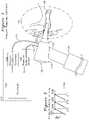
- FIG. 1shows a diagram of a pressure response controller coupled to a human ear canal.
- FIG. 2shows amplitude transfer plots and phase transfer plots for various effusion conditions.
- FIGS. 3A, 3B, 4, and 5show plots for various volume excitation methods and responses.
- FIG. 6shows a block diagram of an otoscope measuring a tympanic membrane displacement in response to a displacement source.
- FIG. 1shows an otoscope 130 which includes a speculum tip 116 for insertion into an ear canal of a subject to be characterized.
- a lens 126is coupled to an optical unit 114 which provides for examination of the outer ear as is provided by a prior art otoscope such as the Welch Allyn 25070-M.
- a pressure excitation generator 106couples a volume change from an excitation generator through hose 112 to the speculum tip 116 , and a pressure measurement hose to a pressure sensor 108 provides a measurement of pressure change in the speculum tip 116 from the excitation generator change in volume.
- the speculum tip 116may be sealed where it attaches to the optical unit 114 to minimize the volume being excited to include only the ear canal and speculum tip 116 volume, or the speculum tip 116 may be sealed to the ear canal in other locations including the concha and tragus at the entrance to the ear canal or in any location which completes a seal to the ear canal.
- a conformable seal 120When inserted into the ear canal of a subject (detail 122 ), a conformable seal 120 may be used which comfortably seals the speculum tip 116 , thereby providing effective coupling of volume changes generated by volume excitation generator 106 to the inner ear and tympanic membrane 124 .
- Volume (or pressure) excitation generator 106may be any of: a voice coil integrated with a movable diaphragm, a diaphragm coupled to a piston actuator, or any mechanism modulating a volume or introducing an external pressure source which is coupled to speculum tip 116 to cause a change in pressure (such as by a change in enclosed volume or introduction and removal of a gas such as air from a fixed volume) which couples the change in pressure into the speculum tip 116 and to the tympanic membrane.
- a volume modulating devicesuch as a diaphragm or piston is described, however it is understood that the pressure change generated by the pressure excitation generator 105 may be formed by any volume displacement method.
- the volume changeis intended to result in a very slight change in position of the tympanic membrane 124 . If there is no fluid present behind the tympanic membrane 124 , the tympanic membrane is able to move freely and accommodate slowly changing (low frequency) changes in volume with negligible changes in pressure. If fluid is present behind the tympanic membrane 124 , the tympanic membrane will exhibit reduced displacement for high frequency pressure change.
- the tympanic membranemay be less able to respond to high frequency changes in volume, which result in greater pressure changes for a given incremental volume change when fluid is present adjacent to the less mobile tympanic membrane, and the greater the mass of the fluid present, the greater the constriction for movement of the tympanic membrane at lower frequencies, resulting in greater induced pressures at greater frequencies.
- FIG. 2frequency response plot showing differential pressure change ( ⁇ P) divided by differential volume change ( ⁇ V) as a function of frequency, scaled to unity for ⁇ P/ ⁇ V of an immobile TM.
- ⁇ Pdifferential pressure change
- ⁇ Vdifferential volume change
- a pressure change vs volume change response plot for a healthy earis shown in plot 208 , which develops minimal pressure changes for incremental volume change at low frequencies because the mobile tympanic membrane without adjacent fluid coupling tracks displacement changes of the excitation generator, so the volume of the system remains relatively fixed and minimal pressure change results.
- Fluid adjacent to the TMwhich adds mass and restricts movement of the TM at higher frequencies results in incremental speculum 116 pressure at lower frequency 212 of plot 206 , and “glue ear” where the TM is immobile results in the response plot 204 with associated corner frequency 210 , where changes in volume result in greater incremental pressures.
- the plots of FIG. 2show transfer functions of pressure/volume versus frequency such as a sinusoidal volume modulation measured as a transfer function of pressure versus frequency.
- Each of the plotswhich has a corner frequency where the transfer function flattens as the frequency is increased.
- Low frequency volume changeswhich do not produce a pressure change in the ear indicate the tympanic membrane is moving freely at that frequency, and as the tympanic membrane is unable to move freely because of increased inertia of adjacent fluid coupling, the pressure increases, as shown in the plots of FIG. 2 for various states of the tympanic membrane.
- a healthy tympanic membranewhich is free to move over a wide range of frequencies without resistance is shown as waveform 208 with a corner frequency of 214 .
- the mobility of the tympanic membrane 124is reduced such that it no longer is able to respond to moderate frequencies ( 212 ) and develops speculum pressure modulations at these frequencies, as indicated by the pressure/volume response plot 206 .
- the final stage of ear infectionwhere bacterial matter with greater density than viral watery fluid collects on the tympanic membrane and becomes “glue ear”, further reduces the amplitude response and frequency range and is shown with plot 204 , indicating that the tympanic membrane does not move in response to volume/pressure excitations except at the lowest pressure excitation frequencies 210 .
- Each corner frequency 210 , 212 , and 214is determined by the mass and volume of fluid which restricts the TM movement.
- FIG. 3Ashows another perspective and method for characterization of the TM using a frequency domain excitation plot 302 (a sinusoidal volume change) with corresponding pressure (used as a proxy for tympanic membrane position) 306 .
- a plot of phase delay 310 and amplitudemay be derived from the response waveform 306 .
- the phase and amplitude responsesmay be collected in by using a chirped frequency excitation which varies in period for successive repeated cycles, thereby measuring the tympanic membrane displacement response (via pressure) to a volume excitation (chirped frequency displacement) in a single frequency sweep.
- the transfer function for the tympanic membranemay be determined as the familiar plot of amplitude of 306 normalized to the amplitude of waveform 302 with phase delay 310 expressed in angle, both measured as a function of frequency.
- the transfer function amplitude and phasemay be used clinically where thresholds are established for frequencies where the amplitude transfer function has dropped 3 dB or 6 dB, or the phase lags by 45 degrees, to establish frequency break points, where the frequency break point may be used as a mobility metric, with a high frequency break point indicating normal ear, a lower frequency break point indicating effusion, and a yet lower frequency break point indicating glue ear.
- FIG. 3Bshows an alternative time domain response, where a step change 320 in volume is momentarily applied, and a pressure response plot 326 is observed, similarly having a time domain delay 324 , as well as some rounding of the response associated with loss of high frequency components from the mechanical inertia of the tympanic membrane and adjacent fluid, with the time delay 324 and extent of rounding associated with mobility of the tympanic membrane, which is also a proxy for whether no effusion, watery effusion, or dense bacterial mucoid effusion is present.
- the measurement metric using the response 326 of FIG. 3Bmay use time response thresholds to establish health of the tympanic membrane, where a comparatively long time response 324 indicates glue ear, a shorter response indicating effusion, and a yet shorter response indicating a normal ear.
- a trapezoidal pressure excitation 402is applied by the controller, and the measured pressure 406 in the speculum tip 406 is examined to determine a settling time t1 404 where the temporal rate of change in pressure is reduced to an exemplar 1 ⁇ 4 of its initial rate of change value, or is selected to be a particular fixed time 404 , whichever occurs first.
- the difference dP(t)is formed by averaging several instances of ⁇ V (t) and ⁇ P(t).
- the volume excitation ⁇ V(t) rise time Tr 401is varied over several successive cycles in sets, each set of pressure excitations being identical with the pressure response of each cycle averaged to provide a composite ⁇ P(t) to provide both a reliable pressure response for each set of cycles, as well as vary the rise time Tr 401 over different sets of measurement cycles to characterize the tympanic membrane for a variety of pressure excitation rise times.
- delta V rise time 401is reduced to a minimum and the pressure response rise time 405 from 0 to tr and fall time 406 from tr to t2 are examined and fit to a curve.
- pressure rise time response 405or difference rise time 409
- P r (t)k1(1 ⁇ e ⁇ t/ ⁇ 1 )
- a burst of sinusoidal volume excitation 302 of 5 cycles or moreis provided as ⁇ V(t), each cycle of the burst being used to average the measured pressure waveform ⁇ P(t) for a single cycle at frequency f to provide a pressure response point for a particular frequency f1, thereafter computing the frequency transfer function
- the resultant transfer function response corner frequencies 214 , 212 , 210 of FIG. 2may thereafter be similarly used as threshold frequencies to determine normal tympanic membrane response, watery fluid behind the tympanic membrane, and mucoid or glue ear tympanic membrane response, respectively.
- Each of the above methods as described for FIGS. 2, 3A, 3B, 4, and 5may be used in a differential method, by comparing results from a left and right ear, in the case where ear infection of only one ear is clinically suspected.
- the differential comparison method of a healthy appearing ear and an ear suspected of infectionmay provide normalization of diagnostic thresholds compared to models developed from the general population. For example, a factor of 2 difference in a frequency break point of FIG. 2 or 3A , or a factor of 2 difference in time response of FIG. 3B or 4 between a presumed healthy and suspected infected ear may be used to establish effusion, and a factor of 4 or greater may be used to establish glue ear.
- the signatures of the pressure responsesare examined for evidence of a seal 120 leak.
- a pressure leak to the ear canalis present, the high frequency transfer is adversely affected, if the seal leak is large enough, no pressure will be measured in response to a pressure excitation.
- An example of a speculum tip leakis shown in the pressure plots 420 and 422 of FIG. 4 , where the change in piston/diaphragm volume 402 causes a transient positive pressure 420 followed by a transient negative pressure 422 when the piston/diaphragm moves in the opposite direction.
- the duration of the measured pressure waveform 420 and 422may be examined to determine any of several conditions which may identify a poor speculum tip seal 120 , not limited to:
- FIG. 6shows an alternative tympanic membrane displacement measurement system comprising piston (or diaphragm) 606 which is sealed 604 to create a closed chamber 608 with the displacement volume coupled via hose 112 to speculum tip 116 with optical viewer 126 .
- Piston actuator 602(which may be a voice coil actuator or other electromagnetic actuator) causes piston 606 to move along the axis of chamber 608 , with the displacement measured by sensor 614 coupled to displacement measurement 618 .
- a central controller 601issues commands for the piston actuator 602 to cause the piston 606 to modulate position, with the displacement measured 618 and reported to controller 601 .
- the controller 601also reads a pressure measurement 616 of the pressure developed in the speculum tip 116 delivered from chamber 608 to the speculum tip 116 via hose 112 .
- the piston diameter 606is selected to have the same approximate diameter of a pediatric (or adult) tympanic membrane.
- the piston 606 displacementis modulated and pressure 110 measured.
- the output value of displacement measurement 618may be regarded as a proxy for the tympanic membrane movement.
- the piston 606 displacementmay be regarded as a proxy for the movement of the tympanic membrane.
- the piston 606 displacementis a swept frequency and a break point in the measured pressure measurement 616 frequency response is noted, this frequency break point represents the excitation frequency where the mobility of the tympanic membrane 124 is adversely affected by the mass of adjacent fluid which is preventing the high frequency modulation of the tympanic membrane 124 .
- Alternative diaphragm pressure actuator 603is shown in view 650 , where a voice coil 660 with leads 658 is actuated when a current is developed which causes attraction or repulsion with permanent magnet 656 , thereby displacing diaphragm 652 with respect to flexible support 654 which provides high frequency response for diaphragm 652 in enclosed volume 608 , with coupling to speculum tip 610 as before, or the excitation generator may be enclosed in speculum tip 116 of FIG. 1 , or adjacent enclosure 114 .
Landscapes
- Health & Medical Sciences (AREA)
- Life Sciences & Earth Sciences (AREA)
- Engineering & Computer Science (AREA)
- Physics & Mathematics (AREA)
- Surgery (AREA)
- Medical Informatics (AREA)
- Pathology (AREA)
- Veterinary Medicine (AREA)
- Biophysics (AREA)
- Biomedical Technology (AREA)
- Heart & Thoracic Surgery (AREA)
- Public Health (AREA)
- Molecular Biology (AREA)
- Animal Behavior & Ethology (AREA)
- General Health & Medical Sciences (AREA)
- Audiology, Speech & Language Pathology (AREA)
- Radiology & Medical Imaging (AREA)
- Optics & Photonics (AREA)
- Acoustics & Sound (AREA)
- Nuclear Medicine, Radiotherapy & Molecular Imaging (AREA)
- Multimedia (AREA)
- Artificial Intelligence (AREA)
- Computer Vision & Pattern Recognition (AREA)
- Physiology (AREA)
- Psychiatry (AREA)
- Signal Processing (AREA)
- Otolaryngology (AREA)
- Measuring And Recording Apparatus For Diagnosis (AREA)
Abstract
Description
- Pr(t) is rise time of405 or409 from 0 to tr;
- Pf(t) is the fall time of406 or408 offset to 0 at t2;
- t is time (x axis of the plots);
- k1 is an amplitude scaling constant;
- τ1 is the rise time coefficient to be determined by curve fit matching, having units of time;
- τ2 is the fall time coefficient to be determined, by curve fit matching, having the units of time.
for each frequency f. The resultant transfer function
Claims (21)
Priority Applications (9)
| Application Number | Priority Date | Filing Date | Title |
|---|---|---|---|
| US15/995,793US11445942B2 (en) | 2018-06-01 | 2018-06-01 | Acoustic otoscope |
| AU2018425465AAU2018425465B2 (en) | 2018-06-01 | 2018-09-19 | Acoustic otoscope |
| PCT/US2018/051817WO2019231485A1 (en) | 2018-06-01 | 2018-09-19 | Acoustic otoscope |
| CA3101589ACA3101589A1 (en) | 2018-06-01 | 2018-09-19 | Acoustic otoscope |
| EP18920314.4AEP3801192A4 (en) | 2018-06-01 | 2018-09-19 | ACOUSTIC OTOSCOPE |
| CN201880096173.4ACN112512400B (en) | 2018-06-01 | 2018-09-19 | Acoustic Otoscope |
| KR1020207036060AKR102747286B1 (en) | 2018-06-01 | 2018-09-19 | Acoustic otoscope |
| JP2020566960AJP7387648B2 (en) | 2018-06-01 | 2018-09-19 | acoustic otoscope |
| US17/880,013US20230172493A1 (en) | 2018-06-01 | 2022-08-03 | Acoustic otoscope |
Applications Claiming Priority (1)
| Application Number | Priority Date | Filing Date | Title |
|---|---|---|---|
| US15/995,793US11445942B2 (en) | 2018-06-01 | 2018-06-01 | Acoustic otoscope |
Related Child Applications (1)
| Application Number | Title | Priority Date | Filing Date |
|---|---|---|---|
| US17/880,013ContinuationUS20230172493A1 (en) | 2018-06-01 | 2022-08-03 | Acoustic otoscope |
Publications (2)
| Publication Number | Publication Date |
|---|---|
| US20190365292A1 US20190365292A1 (en) | 2019-12-05 |
| US11445942B2true US11445942B2 (en) | 2022-09-20 |
Family
ID=68694847
Family Applications (2)
| Application Number | Title | Priority Date | Filing Date |
|---|---|---|---|
| US15/995,793Active2040-08-26US11445942B2 (en) | 2018-06-01 | 2018-06-01 | Acoustic otoscope |
| US17/880,013PendingUS20230172493A1 (en) | 2018-06-01 | 2022-08-03 | Acoustic otoscope |
Family Applications After (1)
| Application Number | Title | Priority Date | Filing Date |
|---|---|---|---|
| US17/880,013PendingUS20230172493A1 (en) | 2018-06-01 | 2022-08-03 | Acoustic otoscope |
Country Status (8)
| Country | Link |
|---|---|
| US (2) | US11445942B2 (en) |
| EP (1) | EP3801192A4 (en) |
| JP (1) | JP7387648B2 (en) |
| KR (1) | KR102747286B1 (en) |
| CN (1) | CN112512400B (en) |
| AU (1) | AU2018425465B2 (en) |
| CA (1) | CA3101589A1 (en) |
| WO (1) | WO2019231485A1 (en) |
Cited By (1)
| Publication number | Priority date | Publication date | Assignee | Title |
|---|---|---|---|---|
| US12137871B2 (en) | 2019-01-25 | 2024-11-12 | Otonexus Medical Technologies, Inc. | Machine learning for otitis media diagnosis |
Families Citing this family (5)
| Publication number | Priority date | Publication date | Assignee | Title |
|---|---|---|---|---|
| US11445942B2 (en)* | 2018-06-01 | 2022-09-20 | Otonexus Medical Technologies, Inc. | Acoustic otoscope |
| AU2020264452A1 (en) | 2019-04-30 | 2021-11-25 | Otonexus Medical Technologies, Inc. | Systems and methods for simulating a tympanic membrane |
| US12256903B2 (en)* | 2019-07-26 | 2025-03-25 | University Of Florida Research Foundation, Inc. | Calibrated pneumatic otoscope |
| WO2022010804A1 (en)* | 2020-07-06 | 2022-01-13 | Otonexus Medical Technologies, Inc. | Otoscope seal devices and methods |
| WO2022251142A1 (en)* | 2021-05-25 | 2022-12-01 | Otonexus Medical Technologies, Inc. | Methods and systems for automated pneumatic otoscopy |
Citations (33)
| Publication number | Priority date | Publication date | Assignee | Title |
|---|---|---|---|---|
| US4237905A (en)* | 1979-07-31 | 1980-12-09 | Electro Audio Dynamics, Inc. | Automatic tympanometric testing means |
| US5699809A (en)* | 1985-11-17 | 1997-12-23 | Mdi Instruments, Inc. | Device and process for generating and measuring the shape of an acoustic reflectance curve of an ear |
| US5919130A (en) | 1995-03-14 | 1999-07-06 | Welch Allyn, Inc. | Video otoscope |
| US6126614A (en)* | 1998-01-12 | 2000-10-03 | Mdi Instruments, Inc. | Apparatus and method for analysis of ear pathologies by detecting fluid in the ear, measuring body temperature and/or determining a characteristic of a fluid |
| EP0871850B1 (en) | 1995-01-26 | 2002-12-04 | MDI Instruments, Inc. | A device and process for generating and measuring the shape of an acoustic reflectance curve of an ear |
| US20030171655A1 (en)* | 2002-03-08 | 2003-09-11 | Newman Richard W. | Combination otoscope |
| US20030220585A1 (en)* | 2002-05-21 | 2003-11-27 | Hissong James B. | Apparatus and method for displacing the partition between the middle ear and the inner ear using a manually powered device |
| US20070112279A1 (en)* | 2005-11-16 | 2007-05-17 | Etymotic Research, Inc. | System and method for performing a hearing screening |
| US20070129632A1 (en)* | 2005-11-14 | 2007-06-07 | Spentech, Inc. | Ultrasound tympanoscope |
| US7399275B2 (en)* | 2003-07-28 | 2008-07-15 | Welch Allyn, Inc. | Otoscope |
| WO2009157825A1 (en) | 2008-06-24 | 2009-12-30 | Atos Medical Ab | A method and device for diagnosing ear conditions |
| US20100094137A1 (en)* | 2007-03-12 | 2010-04-15 | Worcester Polytechnic Institute | Methods and systems for observation of tympanic function |
| US20100191144A1 (en) | 2009-01-23 | 2010-07-29 | Path Medical Gmbh | Ear canal obstruction detecting acoustical stimulation ear probe |
| US20110224493A1 (en)* | 2010-03-09 | 2011-09-15 | Olabisi Oyadiran | Ear ailment diagnostic device and method |
| US20130023818A1 (en)* | 2009-10-15 | 2013-01-24 | Entratympanic, Llc | Device and method for delivering medicine into the tympanic cavity,with sliding assist |
| US20130289353A1 (en)* | 2010-11-04 | 2013-10-31 | The Cleveland Clinic Foundation | Device and method for determining the presence of middle ear fluid |
| US20150201869A1 (en)* | 2012-03-16 | 2015-07-23 | Mauziar Nikzad | Handheld vibrating medical device for sensory diagnostics |
| US20150216452A1 (en)* | 2014-02-04 | 2015-08-06 | Gn Otometrics A/S | Hearing test probe |
| US20150351616A1 (en)* | 2013-02-04 | 2015-12-10 | Helen Of Troy Limited | Otoscope |
| US20150351607A1 (en)* | 2013-02-04 | 2015-12-10 | Helen Of Troy Limited | Method for identifying objects in a subject's ear |
| US20150351637A1 (en)* | 2013-02-04 | 2015-12-10 | Helen Of Troy Limited | Ear inspection device and method of determining a condition of a subject's ear |
| US20150351606A1 (en)* | 2013-02-04 | 2015-12-10 | Helen Of Troy Limited | Method for identifying objects in a subject's ear |
| US20150374208A1 (en)* | 2013-02-04 | 2015-12-31 | Helen Of Troy Limited | Otoscope |
| US20160128555A1 (en)* | 2014-11-07 | 2016-05-12 | Welch Allyn, Inc. | Medical diagnostic instrument |
| US9468400B2 (en)* | 2014-05-28 | 2016-10-18 | Gn Otometrics A/S | Audiologic test apparatus with dual probe system |
| US20170014053A1 (en) | 2015-07-13 | 2017-01-19 | Otonexus Medical Technologies, Inc. | Apparatus and Method for Characterization of Acute Otitis Media |
| US9867528B1 (en)* | 2013-08-26 | 2018-01-16 | The Board Of Trustees Of The University Of Illinois | Quantitative pneumatic otoscopy using coherent light ranging techniques |
| US20180310917A1 (en)* | 2016-06-04 | 2018-11-01 | Otonexus Medical Technologies, Inc. | Apparatus and Method for Characterization of a Ductile Membrane, Surface, and Sub-surface Properties |
| US20190046089A1 (en)* | 2016-02-09 | 2019-02-14 | Sonova Ag | A method of performing real ear measurements by placing a probe element at an intended position from a tympanic membrane of an individual's ear canal and a measuring system configured to carry out such method |
| US20190200873A1 (en)* | 2017-05-31 | 2019-07-04 | Otonexus Medical Technologies, Inc. | Infrared Otoscope for Characterization of Effusion |
| US20190365292A1 (en)* | 2018-06-01 | 2019-12-05 | Otonexus Medical Technologies, Inc. | Acoustic Otoscope |
| US10568515B2 (en)* | 2016-06-21 | 2020-02-25 | Otonexus Medical Technologies, Inc. | Optical coherence tomography device for otitis media |
| US20210186426A1 (en)* | 2018-09-07 | 2021-06-24 | University Of Washington | System and method for detection of middle ear fluids |
Family Cites Families (13)
| Publication number | Priority date | Publication date | Assignee | Title |
|---|---|---|---|---|
| US4429702A (en)* | 1981-06-22 | 1984-02-07 | Electro Audio Dynamics, Inc. | Apparatus for measurement of acoustic volume |
| JPS60168806U (en)* | 1984-04-19 | 1985-11-09 | リオン株式会社 | Ear probe for impedance audiometer |
| JP3330701B2 (en)* | 1993-10-14 | 2002-09-30 | 俊光 小林 | Middle ear dynamic characteristics measurement and observation device |
| US6002777A (en)* | 1995-07-21 | 1999-12-14 | Stethtech Corporation | Electronic stethoscope |
| US5792073A (en)* | 1996-01-23 | 1998-08-11 | Boys Town National Research Hospital | System and method for acoustic response measurement in the ear canal |
| US5902252A (en)* | 1998-01-23 | 1999-05-11 | Mdi Instruments, Inc. | Device and process for measuring acoustic reflectance |
| US20070261494A1 (en)* | 2006-04-28 | 2007-11-15 | Biomec, Inc. | Ultrasonic transducer devices and detection apparatus |
| KR20100130765A (en)* | 2009-06-04 | 2010-12-14 | 을지대학교 산학협력단 | Ultrasound Probe for Exudative Otitis Media |
| US20120299826A1 (en)* | 2011-05-24 | 2012-11-29 | Alcatel-Lucent Usa Inc. | Human/Machine Interface for Using the Geometric Degrees of Freedom of the Vocal Tract as an Input Signal |
| US9113825B2 (en)* | 2012-07-10 | 2015-08-25 | Fujifilm Sonosite, Inc. | Ultrasonic probe and aligned needle guide system |
| WO2016182999A1 (en)* | 2015-05-08 | 2016-11-17 | Photonicare, Inc. | Otoscope tip and methods of use |
| DE102016203608A1 (en)* | 2016-03-04 | 2017-09-07 | Technische Universität Dresden | Device and system for Doppler Optical Coherence Tomography (OCT) on the human middle ear |
| US20190274917A1 (en)* | 2016-10-30 | 2019-09-12 | Vincent Yuval R&D Limited | Ear therapeutic device |
- 2018
- 2018-06-01USUS15/995,793patent/US11445942B2/enactiveActive
- 2018-09-19JPJP2020566960Apatent/JP7387648B2/enactiveActive
- 2018-09-19CACA3101589Apatent/CA3101589A1/enactivePending
- 2018-09-19KRKR1020207036060Apatent/KR102747286B1/enactiveActive
- 2018-09-19AUAU2018425465Apatent/AU2018425465B2/enactiveActive
- 2018-09-19EPEP18920314.4Apatent/EP3801192A4/enactivePending
- 2018-09-19CNCN201880096173.4Apatent/CN112512400B/enactiveActive
- 2018-09-19WOPCT/US2018/051817patent/WO2019231485A1/ennot_activeCeased
- 2022
- 2022-08-03USUS17/880,013patent/US20230172493A1/enactivePending
Patent Citations (34)
| Publication number | Priority date | Publication date | Assignee | Title |
|---|---|---|---|---|
| US4237905A (en)* | 1979-07-31 | 1980-12-09 | Electro Audio Dynamics, Inc. | Automatic tympanometric testing means |
| US5699809A (en)* | 1985-11-17 | 1997-12-23 | Mdi Instruments, Inc. | Device and process for generating and measuring the shape of an acoustic reflectance curve of an ear |
| EP0871850B1 (en) | 1995-01-26 | 2002-12-04 | MDI Instruments, Inc. | A device and process for generating and measuring the shape of an acoustic reflectance curve of an ear |
| US5919130A (en) | 1995-03-14 | 1999-07-06 | Welch Allyn, Inc. | Video otoscope |
| US6126614A (en)* | 1998-01-12 | 2000-10-03 | Mdi Instruments, Inc. | Apparatus and method for analysis of ear pathologies by detecting fluid in the ear, measuring body temperature and/or determining a characteristic of a fluid |
| US20030171655A1 (en)* | 2002-03-08 | 2003-09-11 | Newman Richard W. | Combination otoscope |
| US20030220585A1 (en)* | 2002-05-21 | 2003-11-27 | Hissong James B. | Apparatus and method for displacing the partition between the middle ear and the inner ear using a manually powered device |
| US7399275B2 (en)* | 2003-07-28 | 2008-07-15 | Welch Allyn, Inc. | Otoscope |
| US20070129632A1 (en)* | 2005-11-14 | 2007-06-07 | Spentech, Inc. | Ultrasound tympanoscope |
| US20070112279A1 (en)* | 2005-11-16 | 2007-05-17 | Etymotic Research, Inc. | System and method for performing a hearing screening |
| US20100094137A1 (en)* | 2007-03-12 | 2010-04-15 | Worcester Polytechnic Institute | Methods and systems for observation of tympanic function |
| WO2009157825A1 (en) | 2008-06-24 | 2009-12-30 | Atos Medical Ab | A method and device for diagnosing ear conditions |
| US20100191144A1 (en) | 2009-01-23 | 2010-07-29 | Path Medical Gmbh | Ear canal obstruction detecting acoustical stimulation ear probe |
| US20130023818A1 (en)* | 2009-10-15 | 2013-01-24 | Entratympanic, Llc | Device and method for delivering medicine into the tympanic cavity,with sliding assist |
| US20110224493A1 (en)* | 2010-03-09 | 2011-09-15 | Olabisi Oyadiran | Ear ailment diagnostic device and method |
| US20130289353A1 (en)* | 2010-11-04 | 2013-10-31 | The Cleveland Clinic Foundation | Device and method for determining the presence of middle ear fluid |
| US20150201869A1 (en)* | 2012-03-16 | 2015-07-23 | Mauziar Nikzad | Handheld vibrating medical device for sensory diagnostics |
| US20150351616A1 (en)* | 2013-02-04 | 2015-12-10 | Helen Of Troy Limited | Otoscope |
| US20150351607A1 (en)* | 2013-02-04 | 2015-12-10 | Helen Of Troy Limited | Method for identifying objects in a subject's ear |
| US20150351637A1 (en)* | 2013-02-04 | 2015-12-10 | Helen Of Troy Limited | Ear inspection device and method of determining a condition of a subject's ear |
| US20150351606A1 (en)* | 2013-02-04 | 2015-12-10 | Helen Of Troy Limited | Method for identifying objects in a subject's ear |
| US20150374208A1 (en)* | 2013-02-04 | 2015-12-31 | Helen Of Troy Limited | Otoscope |
| US9867528B1 (en)* | 2013-08-26 | 2018-01-16 | The Board Of Trustees Of The University Of Illinois | Quantitative pneumatic otoscopy using coherent light ranging techniques |
| US20150216452A1 (en)* | 2014-02-04 | 2015-08-06 | Gn Otometrics A/S | Hearing test probe |
| US9468400B2 (en)* | 2014-05-28 | 2016-10-18 | Gn Otometrics A/S | Audiologic test apparatus with dual probe system |
| US20160128555A1 (en)* | 2014-11-07 | 2016-05-12 | Welch Allyn, Inc. | Medical diagnostic instrument |
| US20170014053A1 (en) | 2015-07-13 | 2017-01-19 | Otonexus Medical Technologies, Inc. | Apparatus and Method for Characterization of Acute Otitis Media |
| US20190046089A1 (en)* | 2016-02-09 | 2019-02-14 | Sonova Ag | A method of performing real ear measurements by placing a probe element at an intended position from a tympanic membrane of an individual's ear canal and a measuring system configured to carry out such method |
| US20180310917A1 (en)* | 2016-06-04 | 2018-11-01 | Otonexus Medical Technologies, Inc. | Apparatus and Method for Characterization of a Ductile Membrane, Surface, and Sub-surface Properties |
| US10568515B2 (en)* | 2016-06-21 | 2020-02-25 | Otonexus Medical Technologies, Inc. | Optical coherence tomography device for otitis media |
| US20190200873A1 (en)* | 2017-05-31 | 2019-07-04 | Otonexus Medical Technologies, Inc. | Infrared Otoscope for Characterization of Effusion |
| US20190365292A1 (en)* | 2018-06-01 | 2019-12-05 | Otonexus Medical Technologies, Inc. | Acoustic Otoscope |
| WO2019231485A1 (en) | 2018-06-01 | 2019-12-05 | Otonexus Medical Technologies, Inc. | Acoustic otoscope |
| US20210186426A1 (en)* | 2018-09-07 | 2021-06-24 | University Of Washington | System and method for detection of middle ear fluids |
Non-Patent Citations (1)
| Title |
|---|
| "International Search Report for PCT/US2018/051817 dated Nov. 19, 2018". |
Cited By (1)
| Publication number | Priority date | Publication date | Assignee | Title |
|---|---|---|---|---|
| US12137871B2 (en) | 2019-01-25 | 2024-11-12 | Otonexus Medical Technologies, Inc. | Machine learning for otitis media diagnosis |
Also Published As
| Publication number | Publication date |
|---|---|
| JP7387648B2 (en) | 2023-11-28 |
| KR20210014119A (en) | 2021-02-08 |
| CN112512400A (en) | 2021-03-16 |
| US20230172493A1 (en) | 2023-06-08 |
| KR102747286B1 (en) | 2024-12-31 |
| EP3801192A1 (en) | 2021-04-14 |
| AU2018425465B2 (en) | 2025-02-20 |
| WO2019231485A1 (en) | 2019-12-05 |
| CA3101589A1 (en) | 2019-12-05 |
| AU2018425465A1 (en) | 2020-12-24 |
| JP2021525597A (en) | 2021-09-27 |
| US20190365292A1 (en) | 2019-12-05 |
| CN112512400B (en) | 2025-04-18 |
| EP3801192A4 (en) | 2022-02-16 |
Similar Documents
| Publication | Publication Date | Title |
|---|---|---|
| US20230172493A1 (en) | Acoustic otoscope | |
| Frear et al. | Impedances of the inner and middle ear estimated from intracochlear sound pressures in normal human temporal bones | |
| Goodman et al. | High-frequency click-evoked otoacoustic emissions and behavioral thresholds in humans | |
| US5594174A (en) | System and method for measuring acoustic reflectance | |
| Kemp et al. | A guide to the effective use of otoacoustic emissions | |
| Voss et al. | Is the pressure difference between the oval and round windows the effective acoustic stimulus for the cochlea? | |
| Farmer-Fedor et al. | Acoustic intensity, impedance and reflection coefficient in the human ear canal | |
| Merchant et al. | Controlled exploration of the effects of conductive hearing loss on wideband acoustic immittance in human cadaveric preparations | |
| Dreisbach et al. | Distortion-product otoacoustic emissions measured at high frequencies in humans | |
| JP2021525597A5 (en) | ||
| Rabinowitz | Acoustic-reflex effects on the input admittance and transfer characteristics of the human middle-ear. | |
| Hecker et al. | A new method to analyze distortion product otoacoustic emissions (DPOAEs) in the high-frequency range up to 18 kHz using windowed periodograms | |
| US20150078561A1 (en) | Method and apparatus for analyzing and visualizing the performance of frequency lowering hearing aids | |
| US20240137712A1 (en) | System, device and method of signal conditioning for earpiece calibration | |
| Huang et al. | Tests of some common assumptions of ear-canal acoustics in cats | |
| Sanborn | Predicting hearing aid response in real ears | |
| Ravicz et al. | Sound pressure distribution within human ear canals: II. Reverse mechanical stimulation | |
| Keefe et al. | Comparing otoacoustic emissions evoked by chirp transients with constant absorbed sound power and constant incident pressure magnitude | |
| Bryant | Comparable Coupler and Real‐Ear Measurements on Supraaural‐and Insert‐Type Earphones | |
| Zwislocki | Normal function of the middle ear and its measurement | |
| Allen et al. | Middle-ear reflectance: Concepts and clinical applications | |
| Wegel | The physical characteristics of audition and dynamical analysis of the external ear | |
| Robinson | Effects of ear-canal geometry and middle-ear pressure on wideband acoustic reflectance | |
| Shanks | An evaluation of three procedures for estimating the volumes of human ear canals as a function of ear-canal pressure and a comparison of static acoustic-immittance values from two measurement systems | |
| Zhao et al. | Assessing middle ear function in humans using multifrequency tympanometry: An overview |
Legal Events
| Date | Code | Title | Description |
|---|---|---|---|
| FEPP | Fee payment procedure | Free format text:ENTITY STATUS SET TO UNDISCOUNTED (ORIGINAL EVENT CODE: BIG.); ENTITY STATUS OF PATENT OWNER: SMALL ENTITY | |
| FEPP | Fee payment procedure | Free format text:ENTITY STATUS SET TO SMALL (ORIGINAL EVENT CODE: SMAL); ENTITY STATUS OF PATENT OWNER: SMALL ENTITY | |
| AS | Assignment | Owner name:OTONEXUS MEDICAL TECHNOLOGIES, WASHINGTON Free format text:ASSIGNMENT OF ASSIGNORS INTEREST;ASSIGNORS:WANG, WEIGANG;CHOI, DONG HO;REEL/FRAME:046197/0536 Effective date:20180625 | |
| AS | Assignment | Owner name:OTONEXUS MEDICAL SYSTEMS, INC., WASHINGTON Free format text:ASSIGNMENT OF ASSIGNORS INTEREST;ASSIGNOR:CHESAVAGE, JAY A.;REEL/FRAME:046505/0543 Effective date:20180707 | |
| AS | Assignment | Owner name:OTONEXUS MEDICAL TECHNOLOGIES, INC., WASHINGTON Free format text:ASSIGNMENT OF ASSIGNORS INTEREST;ASSIGNOR:MOEHRING, MARK A.;REEL/FRAME:046784/0687 Effective date:20180803 | |
| AS | Assignment | Owner name:OTONEXUS MEDICAL TECHNOLOGIES, INC., WASHINGTON Free format text:ASSIGNMENT OF ASSIGNORS INTEREST;ASSIGNORS:MOEHRING, MARK A.;CHESAVAGE, JAY A.;WANG, WEIGANG;AND OTHERS;SIGNING DATES FROM 20200305 TO 20200325;REEL/FRAME:052670/0420 | |
| STPP | Information on status: patent application and granting procedure in general | Free format text:NON FINAL ACTION MAILED | |
| STPP | Information on status: patent application and granting procedure in general | Free format text:NON FINAL ACTION MAILED | |
| STPP | Information on status: patent application and granting procedure in general | Free format text:RESPONSE TO NON-FINAL OFFICE ACTION ENTERED AND FORWARDED TO EXAMINER | |
| STPP | Information on status: patent application and granting procedure in general | Free format text:NOTICE OF ALLOWANCE MAILED -- APPLICATION RECEIVED IN OFFICE OF PUBLICATIONS | |
| STPP | Information on status: patent application and granting procedure in general | Free format text:NOTICE OF ALLOWANCE MAILED -- APPLICATION RECEIVED IN OFFICE OF PUBLICATIONS | |
| STPP | Information on status: patent application and granting procedure in general | Free format text:PUBLICATIONS -- ISSUE FEE PAYMENT VERIFIED | |
| STCF | Information on status: patent grant | Free format text:PATENTED CASE |