US11445937B2 - Medical device with multi-core fiber for optical sensing - Google Patents
Medical device with multi-core fiber for optical sensingDownload PDFInfo
- Publication number
- US11445937B2 US11445937B2US15/400,655US201715400655AUS11445937B2US 11445937 B2US11445937 B2US 11445937B2US 201715400655 AUS201715400655 AUS 201715400655AUS 11445937 B2US11445937 B2US 11445937B2
- Authority
- US
- United States
- Prior art keywords
- cores
- catheter
- distal end
- fiber
- core fiber
- Prior art date
- Legal status (The legal status is an assumption and is not a legal conclusion. Google has not performed a legal analysis and makes no representation as to the accuracy of the status listed.)
- Active, expires
Links
Images


Classifications
- A—HUMAN NECESSITIES
- A61—MEDICAL OR VETERINARY SCIENCE; HYGIENE
- A61B—DIAGNOSIS; SURGERY; IDENTIFICATION
- A61B5/00—Measuring for diagnostic purposes; Identification of persons
- A61B5/06—Devices, other than using radiation, for detecting or locating foreign bodies ; Determining position of diagnostic devices within or on the body of the patient
- A61B5/065—Determining position of the probe employing exclusively positioning means located on or in the probe, e.g. using position sensors arranged on the probe
- G—PHYSICS
- G01—MEASURING; TESTING
- G01K—MEASURING TEMPERATURE; MEASURING QUANTITY OF HEAT; THERMALLY-SENSITIVE ELEMENTS NOT OTHERWISE PROVIDED FOR
- G01K7/00—Measuring temperature based on the use of electric or magnetic elements directly sensitive to heat ; Power supply therefor, e.g. using thermoelectric elements
- G01K7/02—Measuring temperature based on the use of electric or magnetic elements directly sensitive to heat ; Power supply therefor, e.g. using thermoelectric elements using thermoelectric elements, e.g. thermocouples
- A—HUMAN NECESSITIES
- A61—MEDICAL OR VETERINARY SCIENCE; HYGIENE
- A61B—DIAGNOSIS; SURGERY; IDENTIFICATION
- A61B18/00—Surgical instruments, devices or methods for transferring non-mechanical forms of energy to or from the body
- A61B18/04—Surgical instruments, devices or methods for transferring non-mechanical forms of energy to or from the body by heating
- A61B18/12—Surgical instruments, devices or methods for transferring non-mechanical forms of energy to or from the body by heating by passing a current through the tissue to be heated, e.g. high-frequency current
- A61B18/14—Probes or electrodes therefor
- A61B18/1492—Probes or electrodes therefor having a flexible, catheter-like structure, e.g. for heart ablation
- A—HUMAN NECESSITIES
- A61—MEDICAL OR VETERINARY SCIENCE; HYGIENE
- A61B—DIAGNOSIS; SURGERY; IDENTIFICATION
- A61B5/00—Measuring for diagnostic purposes; Identification of persons
- A61B5/02—Detecting, measuring or recording for evaluating the cardiovascular system, e.g. pulse, heart rate, blood pressure or blood flow
- A61B5/024—Measuring pulse rate or heart rate
- A61B5/0245—Measuring pulse rate or heart rate by using sensing means generating electric signals, i.e. ECG signals
- A—HUMAN NECESSITIES
- A61—MEDICAL OR VETERINARY SCIENCE; HYGIENE
- A61B—DIAGNOSIS; SURGERY; IDENTIFICATION
- A61B5/00—Measuring for diagnostic purposes; Identification of persons
- A61B5/68—Arrangements of detecting, measuring or recording means, e.g. sensors, in relation to patient
- A61B5/6846—Arrangements of detecting, measuring or recording means, e.g. sensors, in relation to patient specially adapted to be brought in contact with an internal body part, i.e. invasive
- A61B5/6847—Arrangements of detecting, measuring or recording means, e.g. sensors, in relation to patient specially adapted to be brought in contact with an internal body part, i.e. invasive mounted on an invasive device
- A61B5/6852—Catheters
- A—HUMAN NECESSITIES
- A61—MEDICAL OR VETERINARY SCIENCE; HYGIENE
- A61M—DEVICES FOR INTRODUCING MEDIA INTO, OR ONTO, THE BODY; DEVICES FOR TRANSDUCING BODY MEDIA OR FOR TAKING MEDIA FROM THE BODY; DEVICES FOR PRODUCING OR ENDING SLEEP OR STUPOR
- A61M25/00—Catheters; Hollow probes
- A61M25/01—Introducing, guiding, advancing, emplacing or holding catheters
- A61M25/0105—Steering means as part of the catheter or advancing means; Markers for positioning
- A61M25/0133—Tip steering devices
- A61M25/0147—Tip steering devices with movable mechanical means, e.g. pull wires
- G—PHYSICS
- G01—MEASURING; TESTING
- G01K—MEASURING TEMPERATURE; MEASURING QUANTITY OF HEAT; THERMALLY-SENSITIVE ELEMENTS NOT OTHERWISE PROVIDED FOR
- G01K11/00—Measuring temperature based upon physical or chemical changes not covered by groups G01K3/00, G01K5/00, G01K7/00 or G01K9/00
- G01K11/32—Measuring temperature based upon physical or chemical changes not covered by groups G01K3/00, G01K5/00, G01K7/00 or G01K9/00 using changes in transmittance, scattering or luminescence in optical fibres
- G01K11/3206—Measuring temperature based upon physical or chemical changes not covered by groups G01K3/00, G01K5/00, G01K7/00 or G01K9/00 using changes in transmittance, scattering or luminescence in optical fibres at discrete locations in the fibre, e.g. using Bragg scattering
- G—PHYSICS
- G01—MEASURING; TESTING
- G01K—MEASURING TEMPERATURE; MEASURING QUANTITY OF HEAT; THERMALLY-SENSITIVE ELEMENTS NOT OTHERWISE PROVIDED FOR
- G01K13/00—Thermometers specially adapted for specific purposes
- G01K13/20—Clinical contact thermometers for use with humans or animals
- G—PHYSICS
- G01—MEASURING; TESTING
- G01L—MEASURING FORCE, STRESS, TORQUE, WORK, MECHANICAL POWER, MECHANICAL EFFICIENCY, OR FLUID PRESSURE
- G01L1/00—Measuring force or stress, in general
- G01L1/24—Measuring force or stress, in general by measuring variations of optical properties of material when it is stressed, e.g. by photoelastic stress analysis using infrared, visible light, ultraviolet
- G01L1/242—Measuring force or stress, in general by measuring variations of optical properties of material when it is stressed, e.g. by photoelastic stress analysis using infrared, visible light, ultraviolet the material being an optical fibre
- G01L1/246—Measuring force or stress, in general by measuring variations of optical properties of material when it is stressed, e.g. by photoelastic stress analysis using infrared, visible light, ultraviolet the material being an optical fibre using integrated gratings, e.g. Bragg gratings
- A—HUMAN NECESSITIES
- A61—MEDICAL OR VETERINARY SCIENCE; HYGIENE
- A61B—DIAGNOSIS; SURGERY; IDENTIFICATION
- A61B18/00—Surgical instruments, devices or methods for transferring non-mechanical forms of energy to or from the body
- A61B2018/00005—Cooling or heating of the probe or tissue immediately surrounding the probe
- A61B2018/00011—Cooling or heating of the probe or tissue immediately surrounding the probe with fluids
- A61B2018/00029—Cooling or heating of the probe or tissue immediately surrounding the probe with fluids open
- A—HUMAN NECESSITIES
- A61—MEDICAL OR VETERINARY SCIENCE; HYGIENE
- A61B—DIAGNOSIS; SURGERY; IDENTIFICATION
- A61B18/00—Surgical instruments, devices or methods for transferring non-mechanical forms of energy to or from the body
- A61B2018/00053—Mechanical features of the instrument of device
- A61B2018/00172—Connectors and adapters therefor
- A—HUMAN NECESSITIES
- A61—MEDICAL OR VETERINARY SCIENCE; HYGIENE
- A61B—DIAGNOSIS; SURGERY; IDENTIFICATION
- A61B18/00—Surgical instruments, devices or methods for transferring non-mechanical forms of energy to or from the body
- A61B2018/00315—Surgical instruments, devices or methods for transferring non-mechanical forms of energy to or from the body for treatment of particular body parts
- A61B2018/00345—Vascular system
- A61B2018/00351—Heart
- A—HUMAN NECESSITIES
- A61—MEDICAL OR VETERINARY SCIENCE; HYGIENE
- A61B—DIAGNOSIS; SURGERY; IDENTIFICATION
- A61B18/00—Surgical instruments, devices or methods for transferring non-mechanical forms of energy to or from the body
- A61B2018/00571—Surgical instruments, devices or methods for transferring non-mechanical forms of energy to or from the body for achieving a particular surgical effect
- A61B2018/00577—Ablation
- A—HUMAN NECESSITIES
- A61—MEDICAL OR VETERINARY SCIENCE; HYGIENE
- A61B—DIAGNOSIS; SURGERY; IDENTIFICATION
- A61B18/00—Surgical instruments, devices or methods for transferring non-mechanical forms of energy to or from the body
- A61B2018/00636—Sensing and controlling the application of energy
- A61B2018/00642—Sensing and controlling the application of energy with feedback, i.e. closed loop control
- A—HUMAN NECESSITIES
- A61—MEDICAL OR VETERINARY SCIENCE; HYGIENE
- A61B—DIAGNOSIS; SURGERY; IDENTIFICATION
- A61B18/00—Surgical instruments, devices or methods for transferring non-mechanical forms of energy to or from the body
- A61B2018/00636—Sensing and controlling the application of energy
- A61B2018/00773—Sensed parameters
- A61B2018/00791—Temperature
- A—HUMAN NECESSITIES
- A61—MEDICAL OR VETERINARY SCIENCE; HYGIENE
- A61B—DIAGNOSIS; SURGERY; IDENTIFICATION
- A61B18/00—Surgical instruments, devices or methods for transferring non-mechanical forms of energy to or from the body
- A61B2018/00636—Sensing and controlling the application of energy
- A61B2018/00773—Sensed parameters
- A61B2018/00839—Bioelectrical parameters, e.g. ECG, EEG
- A—HUMAN NECESSITIES
- A61—MEDICAL OR VETERINARY SCIENCE; HYGIENE
- A61B—DIAGNOSIS; SURGERY; IDENTIFICATION
- A61B18/00—Surgical instruments, devices or methods for transferring non-mechanical forms of energy to or from the body
- A61B2018/00988—Means for storing information, e.g. calibration constants, or for preventing excessive use, e.g. usage, service life counter
- A—HUMAN NECESSITIES
- A61—MEDICAL OR VETERINARY SCIENCE; HYGIENE
- A61B—DIAGNOSIS; SURGERY; IDENTIFICATION
- A61B18/00—Surgical instruments, devices or methods for transferring non-mechanical forms of energy to or from the body
- A61B18/04—Surgical instruments, devices or methods for transferring non-mechanical forms of energy to or from the body by heating
- A61B18/12—Surgical instruments, devices or methods for transferring non-mechanical forms of energy to or from the body by heating by passing a current through the tissue to be heated, e.g. high-frequency current
- A61B18/14—Probes or electrodes therefor
- A61B2018/1465—Deformable electrodes
- A—HUMAN NECESSITIES
- A61—MEDICAL OR VETERINARY SCIENCE; HYGIENE
- A61B—DIAGNOSIS; SURGERY; IDENTIFICATION
- A61B34/00—Computer-aided surgery; Manipulators or robots specially adapted for use in surgery
- A61B34/20—Surgical navigation systems; Devices for tracking or guiding surgical instruments, e.g. for frameless stereotaxis
- A61B2034/2046—Tracking techniques
- A61B2034/2061—Tracking techniques using shape-sensors, e.g. fiber shape sensors with Bragg gratings
- A—HUMAN NECESSITIES
- A61—MEDICAL OR VETERINARY SCIENCE; HYGIENE
- A61B—DIAGNOSIS; SURGERY; IDENTIFICATION
- A61B90/00—Instruments, implements or accessories specially adapted for surgery or diagnosis and not covered by any of the groups A61B1/00 - A61B50/00, e.g. for luxation treatment or for protecting wound edges
- A61B90/06—Measuring instruments not otherwise provided for
- A61B2090/064—Measuring instruments not otherwise provided for for measuring force, pressure or mechanical tension
- A—HUMAN NECESSITIES
- A61—MEDICAL OR VETERINARY SCIENCE; HYGIENE
- A61B—DIAGNOSIS; SURGERY; IDENTIFICATION
- A61B2218/00—Details of surgical instruments, devices or methods for transferring non-mechanical forms of energy to or from the body
- A61B2218/001—Details of surgical instruments, devices or methods for transferring non-mechanical forms of energy to or from the body having means for irrigation and/or aspiration of substances to and/or from the surgical site
- A61B2218/002—Irrigation
- A—HUMAN NECESSITIES
- A61—MEDICAL OR VETERINARY SCIENCE; HYGIENE
- A61B—DIAGNOSIS; SURGERY; IDENTIFICATION
- A61B2562/00—Details of sensors; Constructional details of sensor housings or probes; Accessories for sensors
- A61B2562/22—Arrangements of medical sensors with cables or leads; Connectors or couplings specifically adapted for medical sensors
- A61B2562/221—Arrangements of sensors with cables or leads, e.g. cable harnesses
- A61B2562/223—Optical cables therefor
- A—HUMAN NECESSITIES
- A61—MEDICAL OR VETERINARY SCIENCE; HYGIENE
- A61B—DIAGNOSIS; SURGERY; IDENTIFICATION
- A61B2562/00—Details of sensors; Constructional details of sensor housings or probes; Accessories for sensors
- A61B2562/22—Arrangements of medical sensors with cables or leads; Connectors or couplings specifically adapted for medical sensors
- A61B2562/225—Connectors or couplings
Definitions
- This disclosurerelates to medical devices, and particularly to interventional and/or surgical catheters and other elongate medical devices capable of being visualized within a body as well as providing responsive feedback concerning tissue contact with a distal portion of the medical device.
- Atrial arrhythmiacan create a variety of dangerous conditions, including irregular heart rates, loss of synchronous atrioventricular contractions, and blood flow stasis. All of these conditions have been associated with a variety of ailments, including death.
- Cathetersare used in a variety of diagnostic and/or therapeutic medical procedures to diagnose and correct conditions such as atrial arrhythmia, including for example, ectopic atrial tachycardia, atrial fibrillation, and atrial flutter.
- atrial fibrillation therapiesa catheter is manipulated through a patient's vasculature to the patient's heart carrying one or more electrodes which may be used for mapping, ablation, diagnosis, or other treatment.
- the ablation catheterimparts ablative energy to cardiac tissue to create a lesion in the cardiac tissue.
- the lesioned tissueis less capable of conducting electrical signals, thereby disrupting undesirable electrical pathways and limiting or preventing stray electrical signals that lead to arrhythmias.
- the ablation cathetermay utilize ablative energy including, for example, radio-frequency (RF), cryoablation, laser, chemical, and high-intensity focused ultrasound.
- RFradio-frequency
- cryoablationlaser
- chemicalchemical
- high-intensity focused ultrasoundablative energy
- Ablation therapiesoften require precise positioning of the ablation catheter, as well as precise pressure exertion for optimal ablative-energy transfer into the targeted myocardial tissue. Excess force between the ablation catheter tip and the targeted myocardial tissue may result in excessive ablation which may permanently damage the cardiac muscle and/or surrounding nerves. When contact force between the ablation catheter tip and the targeted myocardial tissue is below a target force, the efficacy of the ablation therapy may be reduced, or entirely negated.
- Ablation therapiesare often delivered by making a number of individual ablations in a controlled fashion in order to form a lesion line. To improve conformity of the individual ablations along the lesion line, it is desirable to precisely control the position at which the individual ablations are conducted, the ablation period, and the contact force between the ablation catheter tip and the targeted tissue. All of these factors affect the conformity of the resulting lesion line.
- Catheter localization systemsin conjunction with mapping systems, have vastly improved a clinician's ability to precisely position the ablation catheter tip for an ablation and determine the efficacy of a treatment.
- ablation controller circuitryhas improved the consistency of individual ablation therapies. There are devices that attempt to measure the force exerted between myocardial tissue and the ablation catheter tip.
- Existing designsutilize ablation catheter tips with deformable bodies which deform in response to a force being exerted on the ablation catheter tip.
- Sensorse.g., magnetic, optical, etc.
- controller circuitrythat associates the deformation with a force exerted by the ablation catheter tip.
- existing deformable body designssuffer from both complexity and cost, primarily related to acquisition and delivery of the measurement signal to the proximal end of the catheter.
- the present disclosurerelates to medical devices, and particularly to interventional and/or surgical catheters and other elongate medical devices capable of being visualized within a body as well as providing responsive feedback concerning tissue contact with a distal portion of the medical device.
- a medical device flexing structure assemblycan comprise a multi-core fiber comprising a plurality of cores, and a flexing structure comprising at least one slot.
- Each of the plurality of corescan comprise a fiber Bragg grating, and the flexing structure can be configured to bend in response to a force imparted on the flexing structure.
- a surgical cathetercan comprise a catheter tip assembly coupled to a distal end of a catheter body.
- the catheter tip assemblycan comprise a catheter tip, a flexing structure, and a multi-core fiber, and the multi-core fiber can comprise a plurality of cores.
- a proximal end of the catheter tipcan be coupled to a distal end of the flexing structure, a distal portion of the multi-core fiber passes through an interior portion of the flexing structure, and the flexing structure is configured to bend in response to a force imparted on the catheter tip.
- a surgical cathetercan comprise a catheter tip assembly coupled to a distal end of a catheter body.
- the catheter tip assemblycan comprise an electrode, a ferrule, and a multi-core fiber, and the multi-core fiber can comprise a plurality of cores.
- a proximal end of the electrodecan be coupled to a distal end of the ferrule, a distal portion of the multi-core fiber passes through an interior portion of the flexure, and the electrode is configured to bend in response to a force imparted on the catheter tip.
- FIG. 1is a diagrammatic view of a system that can be used to perform an interventional medical procedure.
- FIG. 2Ais an end view of one embodiment of a multi-core fiber.
- FIG. 2Bis an isometric view of an end of the multi-core fiber of FIG. 2A .
- FIG. 2Cis an isometric view of an end of another embodiment of a multi-core fiber.
- FIG. 3is a diagrammatic view of one embodiment of a force sensing system.
- FIG. 4is an isometric view of one embodiment of a catheter tip comprising a multi-core fiber.
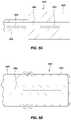
- FIGS. 5A and 5Bare cross-sectional views of other embodiments of a catheter tip comprising a multi-core fiber.
- FIG. 5Cis a cross sectional view of one embodiment of an encasement member.
- FIG. 5Dis a cross-sectional view of another embodiment of a catheter tip comprising a multi-core fiber.
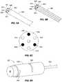
- FIGS. 6A and 6Bare an isometric views of another embodiment of a multi-core fiber.
- FIG. 6Cis an end view of the multi-core fiber of FIGS. 6A and 6B .
- FIG. 6Dis an isometric view of one embodiment a flexing structure comprising a multi-core fiber.
- FIG. 6Eis a side view of the embodiment of a flexing structure illustrated in FIG. 6D .
- FIG. 6Fis a side view of one embodiment of a tip assembly comprising a flexing structure.
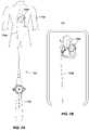
- FIG. 7Ais a diagrammatic view of catheter comprising a multi-core fiber during a procedure.
- FIG. 7Bis a diagrammatic view of a display depicting a catheter shaft.
- the disclosureis generally directed to medical devices.
- Devices and techniquesare disclosed relating to interventional and/or surgical catheters, introducers, and other elongate medical devices capable of being visualized within a body, as well as being capable of providing responsive feedback concerning tissue contact with a distal portion of the medical device.
- a catheter or other elongate medical deviceis equipped with distal force sensing capabilities and elongate body shape sensing capabilities.
- the distal force sensing and elongate body shape sensing capabilitiesare implemented with optical sensing technology.
- optical sensing technologiesmay involve different optical sensing technologies, such as, for example, fiber Bragg grating (FBG) shape sensing and optical interferometer distal force sensing.
- FBGfiber Bragg grating
- embodiments described herein using optical conduitsmay utilize any optical technologies that transmit light via such optical conduits for use in the force and shape sensing mechanisms, whether the implemented force and shape sensing technologies are the same or dissimilar.
- Representative embodiments described hereinalso involve implementing a multi-core fiber(s) to provide the optical conduits through some or all of the catheter or other elongate body.
- FIG. 1illustrates a representative system 10 that may be used in an interventional medical procedure on a body 14 .
- the description hereinmay be described in terms of a particular representative medical procedure and/or body 14 organ(s), it should be recognized that the principals described herein are equally applicable to other procedures and body organs.
- portions of the descriptionmay be described in terms of cardiac procedures and/or in terms of endocardial procedures involving the human heart, the principals described herein are equally applicable to other interventional procedures, such as epicardial procedures, renal denervation or other procedures involving the kidneys, vascular procedures, and the like.
- the system 10includes a medical device, such as a catheter 19 , introducer, or other interventional or surgical device where at least a portion of the device is placed within the body 14 .
- the representative catheter 19includes a catheter electrode assembly 11 shown within the cardiac space within the body 14 , where the electrode assembly 11 is included as part of the catheter 19 or other medical device and may be used, for example, for diagnosis, visualization, and/or treatment of tissue 13 (such as cardiac or other tissue) in the body 14 .
- the electrode assembly 11may be used for ablation therapy of tissue 13 and/or mapping purposes in a patient's body 14 .
- FIG. 1further shows various representative sub-systems included in the overall system 10 .
- the system 10may include a main computing system 15 , which may include a processing system, depicted in FIG. 1 as an electronic control unit (E.C.U.) 16 which represents any individual or distributed processing unit.
- the computing system 15may also include data storage 17 , e.g., memory and/or other storage.
- the computer system 15may further include conventional interface components, such as various user input/output mechanisms 18 a and a display(s) 18 b , among other components.
- Information obtained and/or provided by the electrode assembly 11may be processed by the computer system 15 , and may provide data to the clinician via the input/output mechanisms 18 a and/or the display 18 b , or in other ways as described herein or known in the art.
- the catheter 19may include one or more cable connectors or other interface 20 , a handle 21 , an elongate (e.g., tubular) body or shaft 22 having a proximal portion 23 and a distal portion 24 .
- the distal portion 24does not represent any particular length, but rather distinguishes some usable portion of the shaft 22 within the body 14 from a remainder of the shaft 22 that ultimately couples to the handle 21 or other control mechanism (e.g., robotic controller).
- the catheter 19may also include other conventional components not illustrated herein such as a temperature sensor(s), additional electrodes, corresponding conductors or leads, etc.
- the connector 20may provide mechanical, fluid, optical and/or electrical connections for cables, such as cables 25 , 26 .
- a cable(s) 25may extend from a fluid reservoir 12 and fluid pump 27 , and the computer system 15 .
- the connector 20may comprise conventional components known in the art and, as shown in the illustrated embodiment, may be disposed at the proximal end of the catheter 19 .
- a handle 21provides a portion for a user to grasp or hold the catheter 19 , and may further provide a mechanism for steering or guiding the shaft 22 within the patient's body 14 .
- the handle 21may include a mechanism configured to change the tension on a pull-wire(s) extending through the catheter 19 to the distal portion 24 of the shaft 22 , or may include some other mechanism to steer the shaft 22 .
- the handle 21may be conventional in the art, and it will be understood that the configuration of the handle 21 may vary.
- the handle 21may be configured to provide visual, auditory, tactile and/or other feedback to a user based on information received from the electrode assembly 11 or elsewhere along the shaft 22 .
- any one or more of the handle 21 , computing system 15 , I/O 18 a and/or display 18 bmay include graphical output, light-emitting-diodes or other visual indicators, tone generator, a vibrating mechanical transducer, and/or other indicator(s), the outputs of which could vary in proportion to the signal sensed at the electrode assembly.
- the system 10 of FIG. 1is merely an exemplary system described to provide a representative context in which the principals described herein may be utilized.
- Catheter-based diagnostic and treatment systemshave been widely used for exploration and treatment of various organs or vessels. Such catheters are typically introduced through a vessel leading to the cavity of the organ to be explored or treated, or alternatively may be introduced in other ways such as directly through an incision made in the wall of the organ. This treatment avoids the trauma and extended recuperation times typically associated with open surgical procedures. For purposes of illustration, descriptions below may be described in representative context of a cardiac ablation procedure using an ablation catheter.
- the areas to be treatedmay first be mapped.
- Such mappingmay be performed, for example, when it is desired to selectively ablate current pathways within the heart to treat atrial fibrillation or other electrical cardiac conduction issues.
- the mapping procedureis complicated by difficulties in locating the zone(s) to be treated due to periodic movement of the heart throughout the cardiac cycle.
- Current systemsrely on manual feedback of the catheter and/or impedance measurements to determine when the catheter is properly positioned in the vessel or organ. Better procedure efficacy may be obtained by measuring contact forces with the vessel or organ wall or detecting contact forces applied by the catheter against the organ or vessel wall that may modify the true wall location.
- RF ablation treatmentFor radio frequency (RF) ablation treatment, sustained contact force is beneficial as less contact force may result in poor ablation, and too much force can result in safety issues such as perforating the organ.
- RF ablation treatmentFor radio frequency (RF) ablation treatment, sustained contact force is beneficial as less contact force may result in poor ablation, and too much force can result in safety issues such as perforating the organ.
- a fiber Bragg gratingis a desirable sensor for measuring the force for numerous reasons, such as it does not interfere with electronics and is compact in size.
- the FBGis a type of distributed Bragg reflector constructed in a segment of optical fiber that reflects particular wavelengths of light and transmits all others. This is achieved by creating a periodic variation in the refractive index of the fiber core thorough two light beams interfering. All wavelength lights have weak reflections at refractive index fringes, but only those wavelengths with phase matching condition will reflect back due to resonance effect and all other wavelength will transmit through the fiber.
- both the grating period and the fiber effective indexwill change accordingly, and hence the Bragg wavelength will shift to blue or red wavelength sides.
- the FBGscan be used for force and temperature sensing.
- One advantagederives from the absolute nature of the information-encoding in measuring the wavelength shift, which renders the sensor independent from fluctuating light power or connector losses.
- ⁇ e0.22 for pure silica glass.
- dTis the temperature change.
- the wavelength shiftsare typically of order ⁇ 1 pm/ ⁇ for strain, and 10 pm/° C. for temperature.
- the Yong's modules Eis defined as
- Fthe force
- a 0is the area of the fiber cross section
- L 0is the fiber length
- ⁇ Lis stressed length due to the applied force.
- ⁇ ⁇ ⁇ ⁇ ⁇ B( 1 - ⁇ e ) ⁇ F EA 0 + ( ⁇ + ⁇ ) ⁇ ⁇ ⁇ ⁇ T ( 7 )
- ⁇is the shift of Bragg wavelength
- ⁇ Tis the temperature change
- Fis the applied force
- Eis the Yong's module
- a 0is the area of fiber cross section
- ⁇ eis the photo-elastic constant
- ⁇is the coefficient of linear expansion
- ⁇is the thermo-optic coefficient.
- the present disclosuredescribes a multi-core fiber comprising multiple core fibers that run the length of the fiber.
- the multi-core fibercan assist in limiting the cross-sectional space required within a catheter body for a plurality of independent channels as described herein.
- an FBGwhen an FBG is inscribed on a multi-core fiber (MCFBG), e.g. four core fibers, four FBGs on four fiber cores can act as four sensors, but the overall size still corresponds to that of the single mode fiber. There can be no separate calibration issue, as all four FBGs are in the same fiber. If all cores are constructed substantially the same, the temperature change will correspondingly shift all four Bragg wavelengths, while only the force in the fiber axis direction will shift four Bragg wavelengths in the same mount.
- MCFBGmulti-core fiber
- the fiberWhen force is applied to the MCFBGs with an angle, the fiber will be bent, and thus four FBGs will experience different compression and tension respectively while the Bragg wavelengths will shift to either short or long wavelengths depending on the force amplitude and its direction.
- the end surface of MCFBGsis melted or otherwise amalgamated (e.g., into a ball) to minimize the reflection.
- FIGS. 2A and 2Billustrate a representative multi-core fiber (MCFBG) 200 in accordance with an embodiment
- the MCFBG 200can comprise multiple cores
- the multiple corescan comprise an MCFBG body 210 , a distal end 212 , a central core 202 , a second core 204 , a third core 206 , and a fourth core 208 .
- the MCFBG body 210can comprise glass or plastic materials. These materials can comprise various configurations as would be known to one of skill in the art.
- the MCFBGcan comprise silica among other materials.
- the multiple corescan provide at least optical/light conduits for sensing force impacting the distal portion of a catheter.
- the core diameters and dopants of the multi-core fibercan be the same, or different.
- a central core 202can achieve different refractive effective index, temperature and strain coefficient to improve the force and temperature sensitivity.
- the force and temperature sensitivitycan be improved when the fiber cladding is designed with a structure of small holes or FBGs on multi-core crystal fibers.
- the central core 202may be used to sense temperature changes by way of an optical sensor (e.g., FBG) at distal core section 202 B, which allows temperature compensation for the remaining off-axis cores 204 , 206 , 208 that transmit light to the respective force sensing (e.g., FBG) sections.
- an optical sensore.g., FBG
- the MCFBGcan be disposed along a central axis of a catheter and the central core can be used to sense temperature changes by way of an optical sensor.
- one or more of the other cores present in the MCFBGcan be used to sense temperature changes by way of an optical sensor.
- Each of the off-axis corescan comprise a distal section.
- the MCFBG 200can further comprise a second distal section 204 B, a third distal section 206 B, and a fourth distal section 208 B.
- FIG. 2Cillustrates another embodiment of an MCFBG 250 .
- the MCFBG 250can comprise an MCFBG body 260 , a distal end 266 , a central core 252 , a second core 254 , a third core 256 , and a fourth core 258 .
- the distal end 266 of the MCFBG 250can be melted into a distal cap 262 .
- the distal capcan comprise a ball-like shape. The ball-like shape can be used to minimize reflection from light traveling to the distal end 266 , as depicted in FIG. 2C .
- the distal cap 262can comprise the same material as the MCFBG body 260 .
- the capcan comprise a portion of the MCFBG body that has been crushed. By crushing a distal end of the MCFBG, as with melting, a distal cap can be formed that minimize reflection from light traveling to the distal end of the MCFBG.
- the distal capcan comprise other materials placed on the distal end of the MCFBG.
- the distal capcan comprise an adhesive or other material that can be formed in a desired shape and/or comprise a desired reflective property.
- F 4is the temperature change.
- the amplitude and the direction angles of the forceare expressed as
- FIG. 3is a diagram of a representative force sensing system utilizing a wavelength swept fiber laser source 300 , an optical switch 302 , a 3D waveguide 304 , a computer 310 , a photo detector 308 , a circulator 312 , and a multi-core fiber Bragg gratings 306 .
- the computer 310can comprise a microprocessor.
- the computercan control the wavelength swept fiber laser source 300 to emit an electromagnetic source or other signal.
- the wavelength swept fiber laser source 300can transmit the source signal to the circulator 312 .
- the source signalcan then pass through the optical switch 302 , pass through the 3D waveguide 304 , and travel from a proximal end to a more distal portion of the multi-core fiber Bragg gratings 306 .
- a portion of the signalcan then be reflected and/or refracted towards the proximal end of the multi-core fiber Bragg gratings 306 , through the circulator 312 and to the photo detector 308 .
- the photo detector 308can send a signal to the computer 310 .
- the computercan then process the signal to determine a degree of deflection enacted on a distal end of the multi-core fiber Bragg gratings 306 as described herein.
- the signal returning from the multi-core fiber Bragg gratingscan be directed to a sensor coupled to or part of the computer. While the multi-core fiber Bragg gratings is illustrated separately in the illustrated embodiment, the multi-core fiber Bragg gratings can be placed within a medical device or other object as described throughout this application.
- FIG. 4illustrates an isometric view of a representative catheter tip assembly 400 comprising a tip electrode 408 , a plurality of irrigation holes 410 , an irrigation tube 406 , a multi-core FBG 402 and a force coupler 404 .
- the tip electrode 408can be coupled to the force coupler 404 .
- the force couplercan comprise a deformable body.
- the multi-core FBG 402can be coupled to an interior portion of the force coupler 404 .
- the forcecan be transferred to the force coupler 404 and the multi-core FBG 402 can deform in response to movement of the force coupler 404 .
- signalsinteract with the FBG present within the multi-core FBG and the change in signal can be used to determine the force acting upon the tip electrode.
- FIG. 5Ashows a cross-sectional view of another representative catheter tip assembly 500 .
- the catheter tip assemblycan comprise an electrode 502 , a fiber 506 , an encasement tube 508 , and a ferrule 504 .
- the electrode 502can swivel angularly or be compressed axially.
- the ferrule 504can be coupled to a proximal end of the electrode 502 .
- the ferrule 504can be coupled to the fiber 506 and can be located proximate a proximal end of the electrode 502 .
- An outer surface of the fiber 506can be surrounded by the encasement tube 508 .
- a distal end of the fiber 506 and the encasement tube 508can be coupled to a distal portion of the electrode 502 .
- the distal end of the fiber and the encasement tubecan be free floating within the electrode.
- the fiber 506 and the bonded encasement tube 508can act as the primary spring.
- the fiber 506can comprise a plurality of cores 510 .
- the plurality of corescan run from a proximal end of the fiber to a distal end of the fiber.
- the encased fiber 506can have a length/diameter ratio that is short enough that buckling is precluded under axial compression but long enough to provide bending sensitivity.
- the catheter tip assemblycan comprise a non-irrigated electrode.
- the electrodecan be further configured to couple to an irrigation tube and direct an irrigant to an area exterior the electrode.
- FIG. 5Bshows another embodiment of a catheter tip assembly 520 .
- the catheter tip assembly 520can comprise an electrode 522 , a ferrule 524 , a fiber 526 , and an encasement 528 .
- the electrode 522can comprise at least one deformation mechanism 532 .
- the deformation mechanism 532can comprise corrugations, laser slots, or other mechanisms of deformation which can allow the electrode 522 to deform with a spring constant.
- the overall net spring used in calculationsis a mechanically parallel combination of a spring action for the electrode 522 and from a mechanically parallel spring action provided by the fiber 526 with the encasement 528 .
- An outer surface of the fiber 526can be surrounded by the encasement tube 528 .
- a distal end of the fiber 526 and the encasement tube 528can be coupled to a distal portion of the electrode 522 .
- the distal end of the fiber and the encasement tubecan be free floating within the electrode.
- FIG. 5Cdepicts an embodiment of an encasement member 548 and its encased fiber 546 .
- the encasement member 548can comprise a proximal wall 554 and a distal wall 556 .
- the proximal wall 554 of the encasement member 548can comprise a thinner wall that that of the distal wall 556 .
- the fiber 546can comprise a first set of gratings 550 and a second set of gratings 552 .
- the first set of gratings 550can be proximal of the second set of gratings 552 .
- first set of gratings 552can be adjacent or proximate the proximal wall 554 of the encasement member 548 .
- an outer surface of the fiber 546 at the first set of gratings 550can be surrounded by the proximal wall 554 .
- the second set of gratingscan be adjacent or proximate the distal wall 556 of the encasement member 548 .
- an outer surface of the fiber 546 at the second set of gratings 552can be surrounded by the distal wall 556 .
- the multi-core fiber 546has multiple cores and multiple gratings.
- the first set of gratings 550can used for bending and the second set of gratings 552 can used for axial compression and can be situated in the encasement member 548 at two different axial positions, one with a thin wall and the other with a relatively thicker wall. By using an encasement member with a wall of varying thickness, the sensitivities of bending and compression to be independently manipulated.
- the gratings 550 and 552can be included in a common set of cores, or may be included in two separate sets of cores, or a combination thereof (e.g., where the central core for temperature compensation is shared, and separate sets of cores may be used for each of set of three force sensing cores).
- a thicker wallcan be in a more proximate location and a thinner wall can be located in a more distal location.
- the wallcan vary in thickness along its length. In other embodiments, the wall can slope from a first diameter to a second diameter. In one embodiment, the wall can slope from a thinner portion in a proximal location to a thicker portion in a more distal location. In another embodiment, the wall can slope from a thicker portion in a proximal location, to a thinner portion in a more distal location. Further, several step changes in thickness along a length of the encasement member are also contemplated.
- FIG. 5Ddepicts another embodiment of a catheter tip assembly 560 .
- the catheter tip assemblycan comprise an electrode 562 , a ferrule 564 , and a multicore fiber 566 .
- a distal end of the multicore fiber 566can be coupled to a distal portion of the electrode 562 .
- a distal end of the multicore fibercan be free floating within the electrode 562 .
- a distal end of the multicore fibercan be held in place against a distal portion of the electrode while not adhered or otherwise coupled to the electrode.
- the multicore fiber 566can held in tension with little or no encasement member.
- the multicore fiber 566can still sense both compression (tension reduction) and bending, where it has an appropriate length/diameter aspect ratio so that it is neither too floppy nor too stiff.
- the length/diameter aspect ratiocan vary depending on the materials that are used to create the multicore fiber, and would be known to one of ordinary skill in the art.
- An embodiment of a medical catheter with a force-sensing capabilitymay provide, for example, a distal diagnostic or therapeutic tip region which is to be juxtaposed against tissue with a force, an intermediate and more proximal extended flexible lumen, a most proximal control handle with which to manipulate the catheter lumen and tip region within a patient's body lumens or organs, a force sensor to sense one or both of a tip bending force and a tip axial force as the distal tip is contacted to a patient's tissue (e.g., cardiac tissue).
- tissuee.g., cardiac tissue
- the force sensormay comprise a combination of a force-displacement calibrated spring and two or more optical displacement sensors capable of reporting one or more deflections of the spring as force is applied to the tip, where the optical displacement sensors comprise two or more Bragg gratings written upon two or more cores of a multicore optical fiber, and where the detected spring deflections permit the tip force to be computed and reported since the spring is calibrated for force versus deflection and deflection is known.
- the optical displacement Bragg sensorsmay utilize wavelength scanning to determine displacement, where the wavelength scanning takes place in, for example, a console into which the catheter is connected, or in the handle of the catheter.
- the multicore fibermay have at least two cores peripheral to the fiber outer diameter, where in a more particular example the multiple cores are angularly distributed about the fiber's central axis in an approximately equally spaced manner.
- the multicore optical fibermay be optically connected to separate fibers using a 3D optical waveguides, which may further involve mounting an optical connector in or on the supporting or control console into which the catheter is plugged.
- the calibrated springincludes a tubular multi-core fiber-encapsulating member whose spring stiffness includes the enclosed fiber.
- the calibrated springincludes a separate spring which operates mechanically in parallel to any spring action provided by the fiber or its containment means, the overall net spring being the simultaneous combination of both springs in parallel.
- the calibrated springis separate from the fiber or its immediate encapsulation member, and the spring provides all of the calibrated spring action employed in force computation. Still another variation involves pre-stretching the fiber in tension or pre-compressing the fiber in compression during manufacture whether or not the fiber is itself encapsulated.
- Another variationincludes a temperature measurement sensor to correct a Bragg grating detected displacement for thermal expansion, where in an even more particular embodiment the temperature sensor is any one of i) a thermocouple, ii) a thermistor, iii) a Bragg grating whose thermal expansion can be deduced optically and thereby acts as a temperature sensor.
- a temperature measurement sensorto correct a Bragg grating detected displacement for thermal expansion
- the temperature sensoris any one of i) a thermocouple, ii) a thermistor, iii) a Bragg grating whose thermal expansion can be deduced optically and thereby acts as a temperature sensor.
- Yet another variation of such a medical devicepositions two or more such Bragg gratings on two or more cores of the fiber, where the gratings have the same axial fiber positions.
- two or more such Bragg ratingsare positioned on a single core of the fiber and have different axial fiber positions.
- two or more Bragg gratings on one or more coresmay have substantially the same grating period, or may have different grating periods.
- a region of the multi-core fiber which contains one or more Bragg gratingsretains the fiber cladding, where in another embodiment the fiber cladding is stripped therefrom.
- the springallows for at least one of a combined tip bending and tip axial compression, tip bending only, or axial compression only, where in a more specific embodiment the two or more Bragg optical displacement sensors detect at least a component of one or more of a bending force and an axial force.
- the net force or force componentis reported as a vector.
- the catheter tipinclude the catheter tip being capable of ablating tissue using a tissue heating or cooling method, the catheter tip being capable of electrically pacing tissue, and the catheter tip being capable of electrically sensing tissue electrical waveforms.
- the force informationmay be displayed on a screen in any numeric, icon or vector form; as an indication that a minimum recommended force has been or has not been attained or has or has-not been maintained, or is used in combination with the time of exposure to the therapy such that a numeric product or index of force and time or force/time integral can be reported.
- the multi-core fiberis designed to prevent fiber buckling.
- one or more optical displacement sensorsare at least one of (a) immersed in flowed irrigant (e.g., saline) and in direct contact with the irrigant/fluid; (b) immersed in flowed irrigant but isolated from the irrigant by an overlying, encapsulating or encasing member or coating; (c) immersed in flowed irrigant but thermally insulated or buffered from the irrigant by an overlying encapsulating or encasing member or coating having a preselected thermal conductivity; (d) immersed in air, a gas or a vacuum; (e) immersed in a deformable gel; (f) mounted in a groove or channel; (g) cast or molded into a surrounding polymeric containing member.
- flowed irrigante.g., saline
- the multi-core optical fiberis also employed with additional Bragg gratings arranged in the intermediate flexible lumen such that the flexing shape of the lumen itself can also be tracked in addition to the tip force.
- the multi-core fiberis also employed to perform optical lesion feedback or optical tissue analysis.
- the temperaturecan be measured or frequently updated by holding the catheter in the blood without applied force. Another option involves using a particular core's FBG (e.g., the center FBG) as a reference as bending will not shift the center FBG wavelength.
- FBGs on three-core or morecan be used to measure the force and temperature in one embodiment, where alternatives include: (a) doping one or more of the cores (e.g., the center core) with a different material than other cores to optimize the parameters to separate the Bragg wavelength shifts of the applied force from the temperature to improve the force and temperature sensitivities; (b) making one or more of the cores a different diameter (e.g., the center core) to optimize the parameters to improve the force and temperature sensitivities; (c) where the cladding of the multi-core fiber is optionally designed with holes to optimize the parameters to improve the force and temperature sensitivities; and (d) where FBGs on multi-core crystal fibers are used as a sensor to improve the force and temperature sensitivities.
- both optical force sensing and optical shape sensingare provided.
- One such manner of providing optical force and shape sensingis described in U.S. Pat. No. 8,622,935, which is incorporated herein by reference in its entirety.
- Optical conduitssuch as optical fiber, may be used to transmit light to optical force sensors that detect forces impacting the catheter tip due to varying contact pressures between the catheter tip and body tissue.
- Other optical conduitsmay be used to transmit light along a desired length of the catheter shaft equipped with optical sensors, in order to enable the real-time position of the sensed portion of the catheter shaft to be positionally tracked and rendered for simulation of the catheter shaft within the body.
- optical sensors used for sensing the force against tissue and for sensing the changing shape of the cathetermay utilize different optical sensing technologies, or a common optical sensing technology.
- optical fibersmay be equipped with fiber Bragg gratings or other optical sensors to determine deflection of a distal portion of a catheter, which is representative of a magnitude and direction of a force bearing upon the catheter tip when contacting tissue during a medical procedure.
- fiber Bragg gratings or other optical sensorsmay also be employed along a length of the catheter shaft that is tracked in real time as the catheter moves and consequently changes shape during the medical procedure.
- the optical fibers used for both force sensing and shape sensingmay be provided as multiple cores of a multi-core fiber.
- the multi-core fiberthus provides the light pathways and optical sensors for both force and shape sensing technologies.
- FIG. 6Adepicts an isometric view of a multi-core fiber 600 .
- the multi-core fiber 600can comprise a plurality of separate cores.
- the multi-core fiber 600can comprise three cores to provide optical conduits for three respective force sensors (not shown).
- the multi-core fiber 600can comprise a first optical core 602 , a second optical core 604 , and a third optical core 606 .
- the multi-core fiber 600can further comprise a first shape sensing core 608 , a second shape sensing core 610 , and a third shape sensing core 612 to provide optical conduits for three respective shape sensing sensors (not shown).
- a particular core located anywhere within the fiberwhich in one embodiment is the central core 614 , may be used to sense temperature changes by way of an optical sensor (e.g., FBG) at a distal core section. Sensing temperature with the central core 614 allows temperature compensation for the remaining off-axis cores 602 - 612 .
- FBGoptical sensor
- four fiberscan be used to derive a force component and a temperature.
- a temperature peak and a normal peakcan both be determined in the same gradient.
- a temperature peak and a normal peakcan both be determined in the same gradient and at the same magnitude.
- FIG. 6Bdepicts an isometric view of the multi-core fiber 600 of FIG.
- FIG. 6Adepicts an end view of the multi-core fiber 600 illustrated in FIGS. 6A and 6B and depicts a representative arrangement of the multiple cores 602 - 612 of fiber 600 from a perspective perpendicular to a longitudinal axis of the fiber 600 .
- only shape sensing coresare implemented, such that only the first shape sensing core 608 , the second shape sensing core 610 , and the third shape sensing core 612 , and optionally an additional core 614 (centrally located or not centrally located), are provided in the multi-core fiber 600 .
- the cores 204 , 206 , 208may be configured as shape sensing cores having a plurality of fiber Bragg gratings along the fiber 200 , and therefore along the catheter shaft in which the fiber is enclosed.
- One or more temperature sensorsmay be included in one or more cores of the fiber, such as was core 202 of FIG. 2B . In such an embodiment, only shape sensing is performed utilizing the multi-core fiber, versus both shape sensing and force sensing.
- both shape sensing and force sensingare implemented using common cores, such that each core includes both shape sensing and force sensing sensors.
- the frequency of lightcan be different in a common core for each of the force and shape sensing gratings respectively, which allows differentiation of the resulting reflections at the sensor signal processing unit.
- FIG. 6Ddepicts an isometric view of one embodiment of a flexing structure assembly 622 .
- the flexing structure assembly 622can comprise an exemplary multi-core fiber 624 implemented in a flexing structure 616 .
- the flexing structure assembly 622can be positioned proximate a distal portion of a catheter shaft.
- the flexing structure 616accommodates distal flexing from which at least the force sensors may sense deflection due to force against a structure, such as cardiac tissue.
- one or more slotsdepicted as slots 618 , 612 , allow the flexing structure 616 to bend due to a force in response to contact with the tissue.
- one or more fiber Bragg grating force sensorsare within three respective cores 602 , 604 , 606 (as seen in FIGS. 6A-6C ), and within the flexing structure 616 , the force sensors can identify deflection of the flexing structure 616 in response to varying degrees of contact with tissue.
- Such sensors based on fiber Bragg gratingmay be implemented as described herein, and/or as described in U.S. Pat. No. 8,182,433 assigned to the assignee of the instant application, which is incorporated herein by reference in its entirety.
- the force sensors associated with the force sensing cores 602 , 604 , 606may utilize a different optical technology.
- FIG. 6Edepicts a side view of the flexing structure 616 depicted in FIG. 6D .
- the flexing structure 616can comprise a plurality of slots 618 , 620 to accommodate bending of the flexing structure 616 in response to contact with a distal end of a catheter.
- FIG. 6Fdepicts a side view of another embodiment of a catheter tip assembly 640 .
- the catheter tip assembly 640can comprise a flexing structure 646 , a catheter tip 652 , a first slot 648 , a second slot 650 , and a multi-core fiber 630 .
- the flexing structure 646can be positioned relative to the catheter tip 652 , such as an ablation and/or mapping tip.
- the catheter tip 652can comprise a plurality of irrigation ports 654 to enable cooling fluid to be discharged from the catheter during a medical procedure.
- the flexing structure 646can be located proximate the catheter tip 652 .
- FIG. 7Aillustrates an exemplary catheter, which is a cardiac ablation catheter 700 in the illustrated embodiment.
- the catheter 700may include a handle 702 for manual operation, or in other embodiments may be implemented in a robotic system (not shown).
- the catheter 700includes a catheter shaft 704 A, which may be guided through the vasculature of a patient's body 706 to the patient's heart 708 A.
- the fiber Bragg grating shape sensing sensorse.g., 602 , 604 , 606 of FIGS. 6A-6C
- a multi-core fibere.g., 600 of FIGS.
- the shape of the catheter shaft 704 Acan be detected and visually recreated as shown by depicted shaft 704 B shown in FIG. 7B .
- the depicted shaft 704 Bas well as a depicted patient's heart 708 B, may be presented on a display 710 .
- the varying force impacting the tip 712 of the shaft 704 Acan be detected as a result of varying degrees of contact with the tissue of the heart 708 A.
- the catheter shaft 704 Amay be viewed as the depicted catheter shaft 704 B via the display 710 , while the degree of contact force on the catheter tip 712 can be concurrently or alternately monitored.
- An embodiment of a medical device incorporating such principlesincludes a manipulatable catheter having a shaft that has distal and proximal portions relative to the manipulating mechanism(s). Within the shaft is a multi-core optical fiber, having a plurality of optical cores dedicated for shape sensing sensors, and a plurality of optical cores dedicated for force sensing sensors.
- At least one of the cores of the multi-core optical fiberis dedicated for temperature compensation, which is used to adjust sensed values obtained from the shape sensing sensors and/or the force sensing sensors.
- the shape sensing sensorsare implemented using one or more fiber Bragg gratings, which reflect light in a perceivable manner when deflected.
- the force sensing sensorsare implemented using one or more fiber Bragg gratings, which also reflect light in a perceivable manner when deflected.
- Other embodimentsimplement fiber Bragg grating technology for both the force sensing and shape sensing sensors, where in yet another embodiment the temperature sensing core also utilizes fiber Bragg grating technology.
- One embodimentinvolves utilizing the multi-core fiber to accommodate only force sensors for detecting distal portion contact with tissue, while in another embodiment the multi-core fiber is utilized to accommodate only shaft shape sensors.
- the shape and force sensing coresare staggered from one another such that every other core is devoted to shape sensors, and the other cores are devoted to force sensors.
- this staggered patternis substantially symmetric, and in still another embodiment a core to accommodate one or more temperature sensors (e.g., fiber Bragg grating) is positioned substantially centrally in the fiber relative to the surrounding, symmetric force and shape sensing cores.
- a flexing structureis provide proximate the force sensors in respective cores of the multi-core fiber to enable the distal portion of the catheter, and thus the included fiber, to deflect. This deflection is perceivable by the fiber Bragg grating or other sensors to provide an indication of an amount of force impacting the distal portion of the catheter.
- proximal and distalmay be used throughout the specification with reference to a clinician manipulating one end of an instrument used to treat a patient.
- proximalrefers to the portion of the instrument closest to the clinician and the term “distal” refers to the portion located furthest from the clinician.
- surgical instrumentsmay be used in many orientations and positions, and these terms are not intended to be limiting and absolute.
- joinder referencese.g., attached, coupled, connected, and the like are to be construed broadly and may include intermediate members between a connection of elements and relative movement between elements. As such, joinder references do not necessarily infer that two elements are directly connected and in fixed relation to each other.
Landscapes
- Health & Medical Sciences (AREA)
- Life Sciences & Earth Sciences (AREA)
- Physics & Mathematics (AREA)
- Engineering & Computer Science (AREA)
- Surgery (AREA)
- General Physics & Mathematics (AREA)
- Biomedical Technology (AREA)
- Public Health (AREA)
- Heart & Thoracic Surgery (AREA)
- Veterinary Medicine (AREA)
- Animal Behavior & Ethology (AREA)
- General Health & Medical Sciences (AREA)
- Molecular Biology (AREA)
- Medical Informatics (AREA)
- Biophysics (AREA)
- Cardiology (AREA)
- Pathology (AREA)
- Plasma & Fusion (AREA)
- Nuclear Medicine, Radiotherapy & Molecular Imaging (AREA)
- Otolaryngology (AREA)
- Mechanical Engineering (AREA)
- Hematology (AREA)
- Anesthesiology (AREA)
- Human Computer Interaction (AREA)
- Pulmonology (AREA)
- Signal Processing (AREA)
- Physiology (AREA)
- Media Introduction/Drainage Providing Device (AREA)
- Surgical Instruments (AREA)
- Endoscopes (AREA)
Abstract
Description
λB=2neffΛ (1)
is the coefficient of linear expansion,
is the thermo-optic coefficient, and dT is the temperature change. For a grating at 1550 nm wavelength, the wavelength shifts are typically of order ˜1pm/με for strain, and 10pm/° C.for temperature.
Where, F is the force, A0is the area of the fiber cross section, L0is the fiber length and ΔL is stressed length due to the applied force. The force is thus derived from Eq. (3) as
F=EA0ε (4)
where ε=ΔL/L0is the stain. For a single mode fiber with a diameter of 125 um, the Yong's modulus of the glass material is 70×109N/m2, then the force with respect to the fiber strain is obtained as
F=859ε(N) (5)
When the ambient temperature remains unchanged dT=0, for a pure glass ρe=0.22, submit Eq. (5) into Eq. (2), the applied force with respect to the shift of the Bragg wavelength is obtained as
F≈1101dλ/λB (6)
For a resolution of 0.01 nm Bragg wavelength shift in 1550 nm wavelength band, the force resolution is given by Eq. (6) as 0.7 gram.
Where Δλ is the shift of Bragg wavelength, ΔT is the temperature change, F is the applied force, E is the Yong's module, A0is the area of fiber cross section, ρeis the photo-elastic constant, α is the coefficient of linear expansion, ξ is the thermo-optic coefficient.
where Aij, i, j=1,2,3,4 represent the sixteen coefficients related to the mechanical assembly and material strengths that can be determined by experiments; Δλii=1,2,3,4 indicate the four shifts of Bragg wavelengths, respectively; Fi, i=1,2,3 represents three components of force, F4is the temperature change. The amplitude and the direction angles of the force are expressed as
Claims (20)
Priority Applications (2)
| Application Number | Priority Date | Filing Date | Title |
|---|---|---|---|
| US15/400,655US11445937B2 (en) | 2016-01-07 | 2017-01-06 | Medical device with multi-core fiber for optical sensing |
| US17/819,247US11998310B2 (en) | 2016-01-07 | 2022-08-11 | Medical device with multi-core fiber for optical sensing |
Applications Claiming Priority (2)
| Application Number | Priority Date | Filing Date | Title |
|---|---|---|---|
| US201662275877P | 2016-01-07 | 2016-01-07 | |
| US15/400,655US11445937B2 (en) | 2016-01-07 | 2017-01-06 | Medical device with multi-core fiber for optical sensing |
Related Child Applications (1)
| Application Number | Title | Priority Date | Filing Date |
|---|---|---|---|
| US17/819,247ContinuationUS11998310B2 (en) | 2016-01-07 | 2022-08-11 | Medical device with multi-core fiber for optical sensing |
Publications (2)
| Publication Number | Publication Date |
|---|---|
| US20170196479A1 US20170196479A1 (en) | 2017-07-13 |
| US11445937B2true US11445937B2 (en) | 2022-09-20 |
Family
ID=57906814
Family Applications (2)
| Application Number | Title | Priority Date | Filing Date |
|---|---|---|---|
| US15/400,655Active2040-01-06US11445937B2 (en) | 2016-01-07 | 2017-01-06 | Medical device with multi-core fiber for optical sensing |
| US17/819,247Active2037-02-03US11998310B2 (en) | 2016-01-07 | 2022-08-11 | Medical device with multi-core fiber for optical sensing |
Family Applications After (1)
| Application Number | Title | Priority Date | Filing Date |
|---|---|---|---|
| US17/819,247Active2037-02-03US11998310B2 (en) | 2016-01-07 | 2022-08-11 | Medical device with multi-core fiber for optical sensing |
Country Status (5)
| Country | Link |
|---|---|
| US (2) | US11445937B2 (en) |
| EP (2) | EP3677206B1 (en) |
| JP (2) | JP6691602B2 (en) |
| CN (1) | CN108430368B (en) |
| WO (1) | WO2017118949A1 (en) |
Cited By (1)
| Publication number | Priority date | Publication date | Assignee | Title |
|---|---|---|---|---|
| US20230200735A1 (en)* | 2018-04-05 | 2023-06-29 | St. Jude Medical International Holding S.À R.L. | Force sensing catheter system |
Families Citing this family (64)
| Publication number | Priority date | Publication date | Assignee | Title |
|---|---|---|---|---|
| DE102015115657B3 (en)* | 2015-09-17 | 2017-02-09 | Harting Ag & Co. Kg | electrical contact element |
| US10610318B2 (en)* | 2016-07-25 | 2020-04-07 | General Electric Company | Augmented reality catheter interface |
| EP3606592B1 (en) | 2017-04-07 | 2025-01-08 | Bard Access Systems, Inc. | Optical fiber-based medical device tracking and monitoring system |
| EP3638997A1 (en)* | 2017-06-15 | 2020-04-22 | FBGS Technologies GmbH | Method and device for measuring force and shape |
| JP6924287B2 (en)* | 2017-08-02 | 2021-08-25 | セント・ジュード・メディカル・インターナショナル・ホールディング・エスエーアールエルSt. Jude Medical International Holding S.a,r.l. | Optical force detection catheter system |
| CN112005075A (en) | 2018-01-24 | 2020-11-27 | 惠曼创新解决方案公司 | Optical fiber system for detecting forces on and measuring deformations of anthropomorphic testing device |
| CN108066881B (en)* | 2018-01-29 | 2021-01-29 | 天津大学 | Vessel intervention catheter, device, contact force detection method and detection device |
| CN108577977B (en)* | 2018-03-19 | 2020-10-30 | 山东大学 | Puncture needle and three-dimensional reconstruction method and system for puncture needle motion trail |
| US11857268B2 (en) | 2018-05-02 | 2024-01-02 | Koninklijke Philips N.V. | Optical shape sensing device with integrated force sensing region and tip integration |
| CN112203609B (en)* | 2018-06-01 | 2024-06-28 | 古河电气工业株式会社 | Detection systems, catheter devices, and laser ablation devices |
| EP4218643B1 (en)* | 2018-06-08 | 2025-07-16 | St. Jude Medical International Holding S.à r.l. | One fiber force and shape sensing |
| US11903683B2 (en)* | 2018-08-03 | 2024-02-20 | Chelak Medical Solutions Inc | Non-barometric determination of hemodynamic effects of cardiac arrhythmias using signals sensed by an implantable device |
| EP3627112A1 (en)* | 2018-09-20 | 2020-03-25 | Koninklijke Philips N.V. | Optical fiber sensor |
| EP3627096A1 (en)* | 2018-09-20 | 2020-03-25 | Koninklijke Philips N.V. | Optical shape sensing system and method |
| US12050098B2 (en) | 2019-02-20 | 2024-07-30 | Humanetics Innovative Solutions, Inc. | Shape sensing system and method for anthropomorphic test devices |
| US20220187146A1 (en)* | 2019-02-20 | 2022-06-16 | Humanetics Innovative Solutions, Inc. | Optical Fiber System For Detecting Forces During A Collision Test |
| EP3928071A4 (en) | 2019-02-20 | 2022-11-16 | Humanetics Innovative Solutions, Inc. | Optical fiber system having helical core structure for detecting forces during a collision test |
| CN111678539B (en)* | 2019-03-11 | 2024-02-13 | 新加坡国立大学 | Fiber Bragg Grating Sensors for Surgical Instruments |
| US11357570B2 (en)* | 2019-04-19 | 2022-06-14 | Lake Region Manufacturing, Inc. | Ablation catheter with fiber Bragg grating strain sensors |
| EP3979919A1 (en)* | 2019-06-06 | 2022-04-13 | VascoMed GmbH | Catheter configured to measure a force acting on the catheter |
| EP4013338A4 (en) | 2019-08-12 | 2023-08-30 | Bard Access Systems, Inc. | SHAPE DETECTION SYSTEMS AND METHODS FOR MEDICAL DEVICES |
| CN110470633B (en)* | 2019-08-20 | 2022-07-19 | 武汉理工大学 | Multi-core fiber grating refractive index sensitive sensor with in-situ self-compensation characteristic |
| EP4061272A4 (en) | 2019-11-25 | 2023-11-22 | Bard Access Systems, Inc. | Shape-sensing systems with filters and methods thereof |
| CN112826497B (en) | 2019-11-25 | 2025-09-09 | 巴德阿克塞斯系统股份有限公司 | Optical tip tracking system and method thereof |
| US12436002B2 (en)* | 2019-12-24 | 2025-10-07 | The University of Melbourne; | Medical device and system and method for guiding positioning of same |
| US11474310B2 (en) | 2020-02-28 | 2022-10-18 | Bard Access Systems, Inc. | Optical connection systems and methods thereof |
| CN215461207U (en)* | 2020-02-28 | 2022-01-11 | 巴德阿克塞斯系统股份有限公司 | Catheter and medical instrument monitoring system |
| CN111580230A (en)* | 2020-03-02 | 2020-08-25 | 华中科技大学 | Flexible optical fiber, preparation method and drivable laser scalpel based on the same |
| US12005216B2 (en) | 2020-03-03 | 2024-06-11 | St. Jude Medical, Cardiology Division, Inc. | Esophageal deviator |
| CN113332561A (en)* | 2020-03-03 | 2021-09-03 | 巴德阿克塞斯系统股份有限公司 | System and method for optical shape sensing and electrical signal conduction |
| JP7600257B2 (en)* | 2020-03-13 | 2024-12-16 | オーエフエス ファイテル,エルエルシー | A system for measuring microbends and arbitrary small deformations along three-dimensional space |
| WO2021186330A1 (en)* | 2020-03-16 | 2021-09-23 | St. Jude Medical International Holding S.À.R.L. | System and method for optical sensor reference frame alignment |
| WO2021202589A1 (en) | 2020-03-30 | 2021-10-07 | Bard Access Systems, Inc. | Optical and electrical diagnostic systems and methods thereof |
| US20210330398A1 (en)* | 2020-04-22 | 2021-10-28 | St. Jude Medical International Holding S.À.R.L. | Single-core fiber and multi-core fiber configurations for medical devices |
| KR20230019116A (en) | 2020-06-03 | 2023-02-07 | 김한준 | Mouthpiece-type Removable Orthodontic Device |
| CN113842536A (en) | 2020-06-26 | 2021-12-28 | 巴德阿克塞斯系统股份有限公司 | Dislocation detection system |
| WO2022005870A1 (en) | 2020-06-29 | 2022-01-06 | Bard Access Systems, Inc. | Automatic dimensional frame reference for fiber optic |
| WO2022011287A1 (en) | 2020-07-10 | 2022-01-13 | Bard Access Systems, Inc. | Continuous fiber optic functionality monitoring and self-diagnostic reporting system |
| WO2022031613A1 (en) | 2020-08-03 | 2022-02-10 | Bard Access Systems, Inc. | Bragg grated fiber optic fluctuation sensing and monitoring system |
| CN114246583A (en) | 2020-09-25 | 2022-03-29 | 巴德阿克塞斯系统股份有限公司 | Fiber Optic Oximetry Systems for Detection and Confirmation |
| CN114344514A (en) | 2020-10-13 | 2022-04-15 | 巴德阿克塞斯系统股份有限公司 | Disinfection enclosure for fiber optic connectors and method thereof |
| US11585706B2 (en) | 2020-10-14 | 2023-02-21 | Lake Region Manufacturing, Inc. | Guidewire with fiber Bragg grating strain sensors |
| CN114518075A (en) | 2020-11-18 | 2022-05-20 | 巴德阿克塞斯系统股份有限公司 | fiber optic stylet holder |
| WO2022115624A1 (en) | 2020-11-24 | 2022-06-02 | Bard Access Systems, Inc. | Steerable fiber optic shape sensing enabled elongated medical instrument |
| WO2022150411A1 (en) | 2021-01-06 | 2022-07-14 | Bard Access Systems, Inc. | Needle guidance using fiber optic shape sensing |
| US12426954B2 (en) | 2021-01-26 | 2025-09-30 | Bard Access Systems, Inc. | Fiber optic shape sensing system associated with port placement |
| CN112985656B (en)* | 2021-02-07 | 2022-03-11 | 上海交通大学 | Force or force shape perception integrated driving wire for flexible robot and application method thereof |
| CN113616329B (en)* | 2021-08-26 | 2023-11-14 | 桂林电子科技大学 | An interventional laser ablation system with in vivo 3D navigation surgery function |
| CN113662657B (en)* | 2021-08-26 | 2023-11-14 | 桂林电子科技大学 | An interventional vascular cancer thrombus ablation medical system with 3D navigation function |
| US11903572B2 (en)* | 2021-09-14 | 2024-02-20 | Nuvasive, Inc. | Surgical instruments, systems, and methods with optical sensors |
| US12419694B2 (en) | 2021-10-25 | 2025-09-23 | Bard Access Systems, Inc. | Reference plane for medical device placement |
| CN113984097B (en)* | 2021-12-27 | 2022-03-15 | 之江实验室 | On-chip demodulation system and bearing equipment for multi-core optical fiber three-dimensional shape sensing |
| CN114459645B (en)* | 2022-01-18 | 2023-05-23 | 武汉理工大学 | A Fiber Bragg Grating Pressure Sensor Based on Arc Hinge |
| US12318149B2 (en) | 2022-03-08 | 2025-06-03 | Bard Access Systems, Inc. | Medical shape sensing devices and systems |
| US12426956B2 (en)* | 2022-03-16 | 2025-09-30 | Bard Access Systems, Inc. | Medical system and method for monitoring medical device insertion and illumination patterns |
| US12089815B2 (en) | 2022-03-17 | 2024-09-17 | Bard Access Systems, Inc. | Fiber optic medical systems and devices with atraumatic tip |
| US20230346482A1 (en)* | 2022-04-27 | 2023-11-02 | Bard Access Systems, Inc. | Conductor Incorporated Fiber Enabled Medical Systems |
| CN119452234A (en) | 2022-04-29 | 2025-02-14 | 瑟拉克医疗解决方案股份有限公司 | Miniaturized systems, devices and methods for interrogation of fiber Bragg gratings integrated into implantable devices |
| CN114983350B (en)* | 2022-05-30 | 2025-03-11 | 上海交通大学 | Bragg sensor and detection method for detecting narrowing of curved blood vessels in space |
| US12343117B2 (en) | 2022-06-28 | 2025-07-01 | Bard Access Systems, Inc. | Fiber optic medical systems and methods for identifying blood vessels |
| US12349984B2 (en) | 2022-06-29 | 2025-07-08 | Bard Access Systems, Inc. | System, method, and apparatus for improved confirm of an anatomical position of a medical instrument |
| CN117481783B (en)* | 2023-12-13 | 2024-07-30 | 成都中医药大学 | Method for controlling pressure of each cavity in software driver |
| DE102024105565A1 (en) | 2024-02-28 | 2025-08-28 | Carl Zeiss Meditec Ag | Control device, robotic assembly and surgical microscope for microsurgery |
| DE102024105566A1 (en) | 2024-02-28 | 2025-08-28 | Carl Zeiss Meditec Ag | Control device, robotic assembly, surgical microscope and method for controlling the movement of a surgical instrument |
Citations (175)
| Publication number | Priority date | Publication date | Assignee | Title |
|---|---|---|---|---|
| DE3020785A1 (en) | 1980-05-31 | 1981-12-10 | Erich 7993 Kressbronn Brosa | Measurement transducer for insertion in narrow tubular bodies - contains shearing force strain gauges located at points of weakness |
| US4757194A (en) | 1986-10-10 | 1988-07-12 | Oxbridge, Inc. | Methods and apparatus for sensing the mechanical application of force |
| EP0281405A2 (en) | 1987-03-06 | 1988-09-07 | THE UNITED STATES OF AMERICA as represented by the Secretary United States Department of Commerce | Oxyhydrogen catalytic thermal tip for angioplasty and the like |
| DE3828550A1 (en) | 1988-08-23 | 1990-03-01 | Rheinmetall Gmbh | Force measuring ring |
| US4918492A (en) | 1987-03-24 | 1990-04-17 | Electricite De France - Service National | Michaelson optical fiber interferometer and its application in particular in the measurement of temperatures |
| WO1990004949A1 (en) | 1988-11-10 | 1990-05-17 | Xintec Corporation | Improved laser-heated intravascular cautery cap |
| US4966597A (en) | 1988-11-04 | 1990-10-30 | Cosman Eric R | Thermometric cardiac tissue ablation electrode with ultra-sensitive temperature detection |
| US4983034A (en) | 1987-12-10 | 1991-01-08 | Simmonds Precision Products, Inc. | Composite integrity monitoring |
| US5014709A (en) | 1989-06-13 | 1991-05-14 | Biologic Systems Corp. | Method and apparatus for high resolution holographic imaging of biological tissue |
| US5018529A (en) | 1986-06-25 | 1991-05-28 | Radisensor Ab | Miniaturized sensor for physiological pressure measurements |
| US5065010A (en) | 1990-08-30 | 1991-11-12 | Camino Laboratories | Fiber optic measurement system having a reference conductor for controlling the energy level of the light source |
| US5104392A (en) | 1985-03-22 | 1992-04-14 | Massachusetts Institute Of Technology | Laser spectro-optic imaging for diagnosis and treatment of diseased tissue |
| US5122137A (en) | 1990-04-27 | 1992-06-16 | Boston Scientific Corporation | Temperature controlled rf coagulation |
| US5174277A (en) | 1990-01-24 | 1992-12-29 | Kabushiki Kaisha Toshiba | Endoscope |
| US5178153A (en) | 1984-03-08 | 1993-01-12 | Einzig Robert E | Fluid flow sensing apparatus for in vivo and industrial applications employing novel differential optical fiber pressure sensors |
| US5201317A (en) | 1988-06-06 | 1993-04-13 | Sumitomo Electric Industries, Ltd. | Diagnostic and therapeutic catheter |
| US5202939A (en) | 1992-07-21 | 1993-04-13 | Institut National D'optique | Fabry-perot optical sensing device for measuring a physical parameter |
| US5279793A (en) | 1992-09-01 | 1994-01-18 | Glass Alexander J | Optical osmometer for chemical detection |
| US5289256A (en) | 1992-02-15 | 1994-02-22 | Daimler-Benz Ag | Integrated-optics expansion interferometer in an extension-metrological neutral environment |
| US5321501A (en) | 1991-04-29 | 1994-06-14 | Massachusetts Institute Of Technology | Method and apparatus for optical imaging with means for controlling the longitudinal range of the sample |
| US5348019A (en) | 1992-09-18 | 1994-09-20 | The Board Of Regents Of The University Of Oklahoma | Optical fiber pressure sensing catheter |
| US5396887A (en) | 1993-09-23 | 1995-03-14 | Cardiac Pathways Corporation | Apparatus and method for detecting contact pressure |
| US5409000A (en) | 1993-09-14 | 1995-04-25 | Cardiac Pathways Corporation | Endocardial mapping and ablation system utilizing separately controlled steerable ablation catheter with ultrasonic imaging capabilities and method |
| US5423807A (en) | 1992-04-16 | 1995-06-13 | Implemed, Inc. | Cryogenic mapping and ablation catheter |
| US5446546A (en) | 1993-07-02 | 1995-08-29 | The Boeing Company | Laser interferometric single piece force transducer |
| US5575787A (en) | 1993-09-20 | 1996-11-19 | Abela Laser Systems, Inc. | Cardiac ablation catheters and method |
| US5594819A (en) | 1995-07-26 | 1997-01-14 | Electric Power Research Institute | Field-mountable fiber optic sensors for long term strain monitoring in hostile environments |
| US5622108A (en) | 1996-01-30 | 1997-04-22 | Universal Screenprinting Systems, Inc. | Screen printing machine |
| US5633494A (en) | 1991-07-31 | 1997-05-27 | Danisch; Lee | Fiber optic bending and positioning sensor with selected curved light emission surfaces |
| US5645065A (en) | 1991-09-04 | 1997-07-08 | Navion Biomedical Corporation | Catheter depth, position and orientation location system |
| WO1997029678A2 (en) | 1996-02-15 | 1997-08-21 | Biosense Inc. | Catheter calibration and usage monitoring system |
| WO1997032182A1 (en) | 1996-02-27 | 1997-09-04 | Massachusetts Institute Of Technology | Method and apparatus for performing optical measurements using a fiber optic imaging guidewire, catheter or endoscope |
| WO1997038637A1 (en) | 1996-04-12 | 1997-10-23 | Novacept | A moisture transport system for contact electrocoagulation |
| JPH09297078A (en) | 1996-05-01 | 1997-11-18 | Atsuhiko Yamagami | Sense sensor by image-processing |
| US5688267A (en) | 1995-05-01 | 1997-11-18 | Ep Technologies, Inc. | Systems and methods for sensing multiple temperature conditions during tissue ablation |
| US5693043A (en) | 1985-03-22 | 1997-12-02 | Massachusetts Institute Of Technology | Catheter for laser angiosurgery |
| US5696863A (en) | 1982-08-06 | 1997-12-09 | Kleinerman; Marcos Y. | Distributed fiber optic temperature sensors and systems |
| WO1998019044A1 (en) | 1996-10-25 | 1998-05-07 | Geoforschungszentrum Potsdam | Anchoring device with strain measurement system |
| JPH10137200A (en) | 1996-11-15 | 1998-05-26 | Tokai Rika Co Ltd | Catheter with sensor mechanism |
| US5769847A (en) | 1994-06-27 | 1998-06-23 | Ep Technologies, Inc. | Systems and methods for controlling tissue ablation using multiple temperature sensing elements |
| US5772590A (en) | 1992-06-30 | 1998-06-30 | Cordis Webster, Inc. | Cardiovascular catheter with laterally stable basket-shaped electrode array with puller wire |
| US5782828A (en) | 1996-12-11 | 1998-07-21 | Irvine Biomedical, Inc. | Ablation catheter with multiple flexible curves |
| US5798521A (en) | 1996-02-27 | 1998-08-25 | The United States Of America As Represented By The Administrator Of The National Aeronautics And Space Administration | Apparatus and method for measuring strain in bragg gratings |
| US5807265A (en) | 1996-01-09 | 1998-09-15 | Kabushiki Kaisha Tokai Rika Denki Seisakusho | Catheter having pressure detecting ability |
| US5833688A (en) | 1997-02-24 | 1998-11-10 | Boston Scientific Corporation | Sensing temperature with plurality of catheter sensors |
| US5844927A (en) | 1995-03-20 | 1998-12-01 | Optoplan As | Optical fiber distributed feedback laser |
| US5858717A (en) | 1997-06-11 | 1999-01-12 | Incyte Pharmaceuticals, Inc. | Human formin binding protein |
| US5904658A (en) | 1996-08-23 | 1999-05-18 | Osteobiologics, Inc. | Hand-held materials tester |
| US5906614A (en) | 1991-11-08 | 1999-05-25 | Ep Technologies, Inc. | Tissue heating and ablation systems and methods using predicted temperature for monitoring and control |
| EP0934728A2 (en) | 1997-11-25 | 1999-08-11 | Eclipse Surgical Technologies, Inc. | Selective treatment of endocardial/myocardial boundary |
| WO1999045994A1 (en) | 1998-03-11 | 1999-09-16 | Dalia Beyar | Remote control catheterization |
| US5967978A (en) | 1993-01-29 | 1999-10-19 | Cardima, Inc. | Intravascular sensing device |
| US6039743A (en) | 1996-01-11 | 2000-03-21 | Intella Interventional Systems, Inc. | Guide wire having distal extremity with adjustable support characteristic and method |
| US6056436A (en) | 1997-02-20 | 2000-05-02 | University Of Maryland | Simultaneous measurement of temperature and strain using optical sensors |
| US6063078A (en) | 1997-03-12 | 2000-05-16 | Medtronic, Inc. | Method and apparatus for tissue ablation |
| US6066120A (en) | 1997-04-30 | 2000-05-23 | Smiths Industries Public Limited Company | Flushable soluble medico-surgical bags |
| US6066102A (en)* | 1998-03-09 | 2000-05-23 | Spectrascience, Inc. | Optical biopsy forceps system and method of diagnosing tissue |
| US6088088A (en) | 1999-03-31 | 2000-07-11 | Hewlett-Packard Company | Chromatic dispersion measurement scheme having high frequency resolution |
| US6102926A (en) | 1996-12-02 | 2000-08-15 | Angiotrax, Inc. | Apparatus for percutaneously performing myocardial revascularization having means for sensing tissue parameters and methods of use |
| JP2000227367A (en) | 1999-02-04 | 2000-08-15 | Shibaura Institute Of Technology | Force sensor using optical fiber and control system using the same |
| US6113593A (en) | 1999-02-01 | 2000-09-05 | Tu; Lily Chen | Ablation apparatus having temperature and force sensing capabilities |
| US6113590A (en) | 1997-11-22 | 2000-09-05 | Forschungszentrum Karlsruhe Gmbh | Heart catheter with means for measuring the contact |
| US6120520A (en) | 1997-05-27 | 2000-09-19 | Angiotrax, Inc. | Apparatus and methods for stimulating revascularization and/or tissue growth |
| US6120476A (en) | 1997-12-01 | 2000-09-19 | Cordis Webster, Inc. | Irrigated tip catheter |
| US6129667A (en) | 1998-02-02 | 2000-10-10 | General Electric Company | Luminal diagnostics employing spectral analysis |
| US6133593A (en) | 1999-07-23 | 2000-10-17 | The United States Of America As Represented By The Secretary Of The Navy | Channel design to reduce impact ionization in heterostructure field-effect transistors |
| US6173091B1 (en) | 1997-11-17 | 2001-01-09 | Northrop Grumman Corporation | Fiber optic Fabry-Perot sensor for measuring absolute strain |
| US6171275B1 (en) | 1998-12-03 | 2001-01-09 | Cordis Webster, Inc. | Irrigated split tip electrode catheter |
| US6175669B1 (en) | 1998-03-30 | 2001-01-16 | The Regents Of The Universtiy Of California | Optical coherence domain reflectometry guidewire |
| US6197023B1 (en) | 1997-04-01 | 2001-03-06 | Axel Muntermann | Apparatus and process for catheter ablation |
| US6210346B1 (en) | 1989-10-11 | 2001-04-03 | Edwards Lifesciences Corp. | Method for inserting an intracranial catheter and for monitoring intracranial pressure in a mammal |
| US6217574B1 (en) | 1998-12-03 | 2001-04-17 | Cordis Webster | System and method for measuring subsurface temperature of tissue during ablation |
| US6226542B1 (en) | 1998-07-24 | 2001-05-01 | Biosense, Inc. | Three-dimensional reconstruction of intrabody organs |
| WO2001033165A1 (en) | 1999-10-29 | 2001-05-10 | Advanced Sensor Technology, Llc | Optical fiber navigation system |
| US6246898B1 (en) | 1995-03-28 | 2001-06-12 | Sonometrics Corporation | Method for carrying out a medical procedure using a three-dimensional tracking and imaging system |
| US6256090B1 (en) | 1997-07-31 | 2001-07-03 | University Of Maryland | Method and apparatus for determining the shape of a flexible body |
| US6262822B1 (en) | 1998-05-13 | 2001-07-17 | Jds Fitel Inc. | Circuit for monitoring optical signals |
| US6266542B1 (en) | 1998-09-24 | 2001-07-24 | Ericsson Inc. | Accessory allowing hands-free operation of a cellular telephone |
| US6272371B1 (en) | 1997-01-03 | 2001-08-07 | Biosense Inc. | Bend-responsive catheter |
| US6276215B1 (en) | 1997-12-05 | 2001-08-21 | Optoplan As | Sensor for measuring strain |
| US20010021843A1 (en) | 2000-03-13 | 2001-09-13 | Siemens Aktiengesellschaft | Medical instrument for insertion into an examination subject, and medical examination/treatment device employing same |
| WO2001074252A2 (en) | 2000-03-31 | 2001-10-11 | Rita Medical Systems Inc. | Tissue biopsy and treatment apparatus and method |
| US6310990B1 (en) | 2000-03-16 | 2001-10-30 | Cidra Corporation | Tunable optical structure featuring feedback control |
| US6324918B1 (en) | 2000-06-05 | 2001-12-04 | Center For Tribology, Inc. | Bidirectional force sensor |
| WO2002019898A2 (en) | 2000-09-07 | 2002-03-14 | Optomed As | Multi-parameter fiber optic probes |
| WO2002019903A1 (en) | 2000-09-07 | 2002-03-14 | Optomed As | Fiber optic probes |
| WO2002023148A1 (en) | 2000-09-15 | 2002-03-21 | Endevco Corporation | Fiber optic pressure sensor |
| US6370412B1 (en) | 1999-10-07 | 2002-04-09 | Massachusetts Institute Of Technology | Method and apparatus for guiding ablative therapy of abnormal biological electrical excitation |
| US20020041722A1 (en) | 2000-08-01 | 2002-04-11 | Johnson Gregg A. | Optical sensing device containing fiber bragg gratings |
| US20020057859A1 (en) | 1999-09-28 | 2002-05-16 | Walter Donald J. | System and method for measuring stress during processing of an optical fiber |
| US6398778B1 (en) | 1999-06-18 | 2002-06-04 | Photonics Research Ontario | Optical fiber diffuser |
| US20020072680A1 (en) | 2000-12-12 | 2002-06-13 | Schock Robert B. | Intra-aortic balloon catheter having a fiberoptic sensor |
| WO2002047751A2 (en) | 2000-12-12 | 2002-06-20 | Datascope Investment Corp. | Intra-aortic balloon catheter having a fiberoptic sensor |
| US6425894B1 (en) | 2000-07-12 | 2002-07-30 | Biosense Webster, Inc. | Ablation catheter with electrode temperature monitoring |
| US6451009B1 (en) | 2000-09-12 | 2002-09-17 | The Regents Of The University Of California | OCDR guided laser ablation device |
| US6458123B1 (en) | 2000-04-27 | 2002-10-01 | Biosense Webster, Inc. | Ablation catheter with positional sensor |
| US6466811B1 (en) | 1999-05-13 | 2002-10-15 | Daig Corporation | Device for the mapping of cardiac arrhyhmia foci |
| US6470286B1 (en) | 1999-06-03 | 2002-10-22 | Robert Bosch Corporation | Ultrasound transducer temperature compensation methods, apparatus and programs |
| US6471710B1 (en) | 1999-08-13 | 2002-10-29 | Advanced Sensor Technology, Llc | Probe position sensing system and method of employment of same |
| US6546271B1 (en) | 1999-10-01 | 2003-04-08 | Bioscience, Inc. | Vascular reconstruction |
| US6547780B1 (en) | 1985-07-31 | 2003-04-15 | Cardiofocus, Inc. | Infrared laser catheter system |
| US6558378B2 (en) | 1998-05-05 | 2003-05-06 | Cardiac Pacemakers, Inc. | RF ablation system and method having automatic temperature control |
| US6563970B1 (en) | 1998-02-27 | 2003-05-13 | Abb Research Ltd. | Pressure sensor with fibre-integrated bragg grating, comprising an integrated temperature sensor with fibre-integrated bragg grating |
| US6572804B2 (en) | 2000-10-18 | 2003-06-03 | Borden Chemical, Inc. | Method for making building panels having low edge thickness swelling |
| US6660001B2 (en) | 2000-01-21 | 2003-12-09 | Providence Health System-Oregon | Myocardial revascularization-optical reflectance catheter and method |
| WO2004002303A1 (en) | 2002-06-26 | 2004-01-08 | Endosense S.A. | Catheterization method and system |
| US6695808B2 (en) | 2000-03-23 | 2004-02-24 | Scimed Life Systems, Inc. | Pressure sensor for therapeutic delivery device and method |
| US6701931B2 (en) | 1996-10-22 | 2004-03-09 | Epicor Medical, Inc. | Methods and devices for ablation |
| US20040082844A1 (en) | 1998-03-05 | 2004-04-29 | Vardi Gil M. | Optical-acoustic imaging device |
| US20040165810A1 (en) | 2003-02-20 | 2004-08-26 | Fuji Photo Optical Co., Ltd. | Device for detecting three-dimensional shapes of elongated flexible body |
| US20040181138A1 (en)* | 2003-03-12 | 2004-09-16 | Gerhard Hindricks | Method for treating tissue |
| US20040206365A1 (en) | 2003-03-31 | 2004-10-21 | Knowlton Edward Wells | Method for treatment of tissue |
| US20040243119A1 (en) | 1999-08-23 | 2004-12-02 | Cryocath Technologies Inc. | Endovascular cryotreatment catheter |
| US6852109B2 (en) | 2002-06-11 | 2005-02-08 | Intraluminal Therapeutics, Inc. | Radio frequency guide wire assembly with optical coherence reflectometry guidance |
| US20050062979A1 (en) | 2003-09-04 | 2005-03-24 | Yizheng Zhu | Optical fiber pressure and acceleration sensor fabricated on a fiber endface |
| US20050085693A1 (en) | 2000-04-03 | 2005-04-21 | Amir Belson | Activated polymer articulated instruments and methods of insertion |
| US6898338B2 (en) | 2001-06-18 | 2005-05-24 | Weatherford/Lamb, Inc. | Fabry-Perot sensing element based on a large-diameter optical waveguide |
| WO2005059510A2 (en) | 2003-12-11 | 2005-06-30 | The Regents Of The University Of California | Catheter-based mid-infrared reflectance and reflectance generated absorption spectroscopy |
| US6915048B2 (en) | 2001-06-18 | 2005-07-05 | Cidra Corporation | Fabry-perot filter/resonator |
| US6947637B2 (en) | 2001-08-09 | 2005-09-20 | Corning Incorporated | Measurement of fiber strain during processing |
| US6955675B2 (en) | 2001-03-01 | 2005-10-18 | Cardiac Pacemakers, Inc. | Ablation catheter with transducer for providing one or more of pressure, temperature and fluid flow data for use in controlling ablation therapy |
| US6986769B2 (en) | 2000-08-21 | 2006-01-17 | Biosense Webster, Inc. | Ablation catheter with cooled linear electrode |
| US20060013523A1 (en) | 2004-07-16 | 2006-01-19 | Luna Innovations Incorporated | Fiber optic position and shape sensing device and method relating thereto |
| US20060045408A1 (en) | 2004-08-27 | 2006-03-02 | Jones Martin P W | Structural member bend radius and shape sensor and measurement apparatus |
| US20060100610A1 (en) | 2004-03-05 | 2006-05-11 | Wallace Daniel T | Methods using a robotic catheter system |
| US7050662B2 (en) | 2003-11-19 | 2006-05-23 | Em Photonics, Inc. | Fiber Bragg grating compression sensor system |
| US20060133715A1 (en) | 2004-12-22 | 2006-06-22 | Claude Belleville | Fiber optic pressure sensor for catheter use |
| US20060200049A1 (en)* | 2005-03-04 | 2006-09-07 | Giovanni Leo | Medical apparatus system having optical fiber load sensing capability |
| US7114938B2 (en) | 1995-11-15 | 2006-10-03 | Regents Of The University Of Minnesota | Lithographic apparatus for molding ultrafine features |
| US20060263002A1 (en) | 2005-05-18 | 2006-11-23 | The Regents Of The University Of California | Silicon fiber optic sensors |
| US20070014490A1 (en) | 2000-05-23 | 2007-01-18 | Silverbrook Research Pty Ltd | Optical force sensor |
| US7173713B2 (en) | 2004-03-04 | 2007-02-06 | Virginia Tech Intellectual Properties, Inc. | Optical fiber sensors for harsh environments |
| WO2007015139A2 (en) | 2005-08-01 | 2007-02-08 | Endosense Sa | Medical apparatus system having optical fiber load sensing capability |
| US20070043338A1 (en) | 2004-03-05 | 2007-02-22 | Hansen Medical, Inc | Robotic catheter system and methods |
| US20070041019A1 (en) | 2003-10-03 | 2007-02-22 | Siegmar Schmidt | Rugged fabry-perot pressure sensor |
| US20070065077A1 (en) | 2004-07-16 | 2007-03-22 | Luna Innovations Incorporated | Fiber Optic Position and Shape Sensing Device and Method Relating Thereto |
| WO2007050960A2 (en) | 2005-10-27 | 2007-05-03 | St. Jude Medical, Atrial Fibrillation Division, Inc. | Systems and methods for electrode contact assessment |
| US20070151390A1 (en) | 2005-03-30 | 2007-07-05 | Blumenkranz Stephen J | Force and Torque Sensing For Surgical Instruments |
| US20070151391A1 (en) | 2005-12-30 | 2007-07-05 | Intultive Surgical Inc. | Modular force sensor |
| US20070156019A1 (en) | 2005-12-30 | 2007-07-05 | Larkin David Q | Robotic surgery system including position sensors using fiber bragg gratings |
| US7241986B2 (en) | 2003-10-08 | 2007-07-10 | Mississippi State University | Fiber ringdown pressure/force sensors |
| US20070265503A1 (en)* | 2006-03-22 | 2007-11-15 | Hansen Medical, Inc. | Fiber optic instrument sensing system |
| WO2008000246A2 (en) | 2006-06-29 | 2008-01-03 | Werthschuetzky Roland | Force sensor and method for detecting at least one force component |
| WO2008003307A2 (en) | 2006-07-06 | 2008-01-10 | Werthschuetzky Roland | Force sensor for the detection of a force vector |
| US20080009750A1 (en) | 2006-06-09 | 2008-01-10 | Endosense Sa | Catheter having tri-axial force sensor |
| WO2008045958A2 (en) | 2006-10-12 | 2008-04-17 | St. Jude Medical, Atrial Fibrillation Division, Inc. | Systems and methods for assessing tissue contact |
| US20080294144A1 (en)* | 2007-05-24 | 2008-11-27 | Giovanni Leo | Touch Sensing Catheter |
| US7460964B2 (en) | 2003-09-16 | 2008-12-02 | Toudai Tlo, Ltd. | Force vector reconstruction method using optical tactile sensor |
| US7466879B2 (en) | 2003-05-22 | 2008-12-16 | Nanyang Technological University | Fiber optic force sensor for measuring shear force |
| US7491957B2 (en) | 2005-11-02 | 2009-02-17 | Minebea Co., Ltd. | Optical displacement sensor |
| US20090138007A1 (en) | 2007-10-08 | 2009-05-28 | Assaf Govari | High-sensitivity pressure-sensing probe |
| US20090137952A1 (en)* | 2007-08-14 | 2009-05-28 | Ramamurthy Bhaskar S | Robotic instrument systems and methods utilizing optical fiber sensor |
| US20090177095A1 (en)* | 2006-06-09 | 2009-07-09 | Nicolas Aeby | Triaxial fiber optic force sensing catheter |
| WO2009114955A1 (en) | 2008-03-19 | 2009-09-24 | Kistler Holding Ag | Optical measuring element having a single-piece structure |
| US20090287092A1 (en) | 2008-05-14 | 2009-11-19 | Giovanni Leo | Temperature compensated strain sensing catheter |
| US20090306643A1 (en) | 2008-02-25 | 2009-12-10 | Carlo Pappone | Method and apparatus for delivery and detection of transmural cardiac ablation lesions |
| US20090306650A1 (en) | 2008-06-06 | 2009-12-10 | Assaf Govari | Catheter with bendable tip |
| US20100063478A1 (en) | 2008-09-09 | 2010-03-11 | Thomas Vaino Selkee | Force-sensing catheter with bonded center strut |
| US20100087835A1 (en) | 2005-12-30 | 2010-04-08 | Blumenkranz Stephen J | Wireless force sensor on a distal portion of a surgical instrument and method |
| US20100094163A1 (en) | 2007-03-07 | 2010-04-15 | Koninklijke Philips Electronics N.V. | Medical apparatus with a sensor for detecting a force |
| US20100312129A1 (en)* | 2005-01-26 | 2010-12-09 | Schecter Stuart O | Cardiovascular haptic handle system |
| US7903907B1 (en) | 2008-04-10 | 2011-03-08 | Intelligent Fiber Optic Systems, Inc. | Force and deflection sensor with shell membrane and optical gratings and method of manufacture |
| US20110087112A1 (en) | 2005-08-01 | 2011-04-14 | Giovanni Leo | Medical apparatus system having optical fiber load sensing |
| US20120132009A1 (en) | 2008-06-30 | 2012-05-31 | Intuitive Surgical Operations, Inc. | Fiber optic shape sensor |
| US20120265184A1 (en)* | 2011-04-13 | 2012-10-18 | St. Jude Medical, Inc. | Optical feedback rf ablator and ablator tip |
| US20120265102A1 (en) | 2011-04-14 | 2012-10-18 | Giovanni Leo | Compact force sensor for catheters |
| US8622935B1 (en) | 2007-05-25 | 2014-01-07 | Endosense Sa | Elongated surgical manipulator with body position and distal force sensing |
| EP2047797B1 (en) | 2007-10-08 | 2014-04-16 | Biosense Webster, Inc. | Catheter with pressure sensing |
| US20140330269A1 (en) | 2007-05-23 | 2014-11-06 | St. Jude Medical, Atrial Fibrillation Division, Inc. | Irrigated flexible ablation catheter |
| US20140364848A1 (en)* | 2011-12-29 | 2014-12-11 | St. Jude Medical, Atrial Fibrillation Division,Inc | System for optimized coupling of ablation catheters to body tissues and evaulation of lesions formed by the catheters |
| US20150029511A1 (en) | 2012-03-16 | 2015-01-29 | Koninklijke Philips N.V. | Optical sensing system for determining the position and/or shape of an associated object |
| US20150182279A1 (en)* | 2013-12-31 | 2015-07-02 | Biosense Webster (Israel), Ltd. | Catheter utilizing optical spectroscopy for measuring tissue contact area |
| WO2015106621A1 (en) | 2014-01-17 | 2015-07-23 | Harbin Institute Of Technology | Method and equipment based on multi-core fiber bragg grating probe for measuring structures of a micro part |
| US9151811B2 (en)* | 2009-03-04 | 2015-10-06 | Imricor Medical Systems, Inc. | MRI compatible medical device temperature monitoring system |
| CN105228514A (en) | 2013-03-15 | 2016-01-06 | 阿维格公司 | Optical pressure sensor assembly |
- 2017
- 2017-01-06USUS15/400,655patent/US11445937B2/enactiveActive
- 2017-01-06WOPCT/IB2017/050066patent/WO2017118949A1/ennot_activeCeased
- 2017-01-06EPEP20157659.2Apatent/EP3677206B1/enactiveActive
- 2017-01-06EPEP17701747.2Apatent/EP3376986B1/enactiveActive
- 2017-01-06CNCN201780005579.2Apatent/CN108430368B/enactiveActive
- 2017-01-06JPJP2018535167Apatent/JP6691602B2/enactiveActive
- 2020
- 2020-03-05JPJP2020038115Apatent/JP6814315B2/enactiveActive
- 2022
- 2022-08-11USUS17/819,247patent/US11998310B2/enactiveActive
Patent Citations (200)
| Publication number | Priority date | Publication date | Assignee | Title |
|---|---|---|---|---|
| DE3020785A1 (en) | 1980-05-31 | 1981-12-10 | Erich 7993 Kressbronn Brosa | Measurement transducer for insertion in narrow tubular bodies - contains shearing force strain gauges located at points of weakness |
| US5696863A (en) | 1982-08-06 | 1997-12-09 | Kleinerman; Marcos Y. | Distributed fiber optic temperature sensors and systems |
| US5178153A (en) | 1984-03-08 | 1993-01-12 | Einzig Robert E | Fluid flow sensing apparatus for in vivo and industrial applications employing novel differential optical fiber pressure sensors |
| US5693043A (en) | 1985-03-22 | 1997-12-02 | Massachusetts Institute Of Technology | Catheter for laser angiosurgery |
| US5104392A (en) | 1985-03-22 | 1992-04-14 | Massachusetts Institute Of Technology | Laser spectro-optic imaging for diagnosis and treatment of diseased tissue |
| US6547780B1 (en) | 1985-07-31 | 2003-04-15 | Cardiofocus, Inc. | Infrared laser catheter system |
| US5018529A (en) | 1986-06-25 | 1991-05-28 | Radisensor Ab | Miniaturized sensor for physiological pressure measurements |
| US4757194A (en) | 1986-10-10 | 1988-07-12 | Oxbridge, Inc. | Methods and apparatus for sensing the mechanical application of force |
| EP0281405A2 (en) | 1987-03-06 | 1988-09-07 | THE UNITED STATES OF AMERICA as represented by the Secretary United States Department of Commerce | Oxyhydrogen catalytic thermal tip for angioplasty and the like |
| US4918492A (en) | 1987-03-24 | 1990-04-17 | Electricite De France - Service National | Michaelson optical fiber interferometer and its application in particular in the measurement of temperatures |
| US4983034A (en) | 1987-12-10 | 1991-01-08 | Simmonds Precision Products, Inc. | Composite integrity monitoring |
| US5201317A (en) | 1988-06-06 | 1993-04-13 | Sumitomo Electric Industries, Ltd. | Diagnostic and therapeutic catheter |
| DE3828550A1 (en) | 1988-08-23 | 1990-03-01 | Rheinmetall Gmbh | Force measuring ring |
| US4966597A (en) | 1988-11-04 | 1990-10-30 | Cosman Eric R | Thermometric cardiac tissue ablation electrode with ultra-sensitive temperature detection |
| WO1990004949A1 (en) | 1988-11-10 | 1990-05-17 | Xintec Corporation | Improved laser-heated intravascular cautery cap |
| US5014709A (en) | 1989-06-13 | 1991-05-14 | Biologic Systems Corp. | Method and apparatus for high resolution holographic imaging of biological tissue |
| US6210346B1 (en) | 1989-10-11 | 2001-04-03 | Edwards Lifesciences Corp. | Method for inserting an intracranial catheter and for monitoring intracranial pressure in a mammal |
| US5174277A (en) | 1990-01-24 | 1992-12-29 | Kabushiki Kaisha Toshiba | Endoscope |
| US5122137A (en) | 1990-04-27 | 1992-06-16 | Boston Scientific Corporation | Temperature controlled rf coagulation |
| US5065010A (en) | 1990-08-30 | 1991-11-12 | Camino Laboratories | Fiber optic measurement system having a reference conductor for controlling the energy level of the light source |
| US6134003A (en) | 1991-04-29 | 2000-10-17 | Massachusetts Institute Of Technology | Method and apparatus for performing optical measurements using a fiber optic imaging guidewire, catheter or endoscope |
| US5321501A (en) | 1991-04-29 | 1994-06-14 | Massachusetts Institute Of Technology | Method and apparatus for optical imaging with means for controlling the longitudinal range of the sample |
| US5633494A (en) | 1991-07-31 | 1997-05-27 | Danisch; Lee | Fiber optic bending and positioning sensor with selected curved light emission surfaces |
| US5645065A (en) | 1991-09-04 | 1997-07-08 | Navion Biomedical Corporation | Catheter depth, position and orientation location system |
| US5906614A (en) | 1991-11-08 | 1999-05-25 | Ep Technologies, Inc. | Tissue heating and ablation systems and methods using predicted temperature for monitoring and control |
| US5289256A (en) | 1992-02-15 | 1994-02-22 | Daimler-Benz Ag | Integrated-optics expansion interferometer in an extension-metrological neutral environment |
| US5423807A (en) | 1992-04-16 | 1995-06-13 | Implemed, Inc. | Cryogenic mapping and ablation catheter |
| US5772590A (en) | 1992-06-30 | 1998-06-30 | Cordis Webster, Inc. | Cardiovascular catheter with laterally stable basket-shaped electrode array with puller wire |
| US5202939A (en) | 1992-07-21 | 1993-04-13 | Institut National D'optique | Fabry-perot optical sensing device for measuring a physical parameter |
| US5392117A (en) | 1992-07-21 | 1995-02-21 | Institut National D'optique | Fabry-Perot optical sensing device for measuring a physical parameter |
| US5279793A (en) | 1992-09-01 | 1994-01-18 | Glass Alexander J | Optical osmometer for chemical detection |
| US5348019A (en) | 1992-09-18 | 1994-09-20 | The Board Of Regents Of The University Of Oklahoma | Optical fiber pressure sensing catheter |
| US5967978A (en) | 1993-01-29 | 1999-10-19 | Cardima, Inc. | Intravascular sensing device |
| US5446546A (en) | 1993-07-02 | 1995-08-29 | The Boeing Company | Laser interferometric single piece force transducer |
| US5409000A (en) | 1993-09-14 | 1995-04-25 | Cardiac Pathways Corporation | Endocardial mapping and ablation system utilizing separately controlled steerable ablation catheter with ultrasonic imaging capabilities and method |
| US5575787A (en) | 1993-09-20 | 1996-11-19 | Abela Laser Systems, Inc. | Cardiac ablation catheters and method |
| US5396887A (en) | 1993-09-23 | 1995-03-14 | Cardiac Pathways Corporation | Apparatus and method for detecting contact pressure |
| US5769847A (en) | 1994-06-27 | 1998-06-23 | Ep Technologies, Inc. | Systems and methods for controlling tissue ablation using multiple temperature sensing elements |
| US5844927A (en) | 1995-03-20 | 1998-12-01 | Optoplan As | Optical fiber distributed feedback laser |
| US6246898B1 (en) | 1995-03-28 | 2001-06-12 | Sonometrics Corporation | Method for carrying out a medical procedure using a three-dimensional tracking and imaging system |
| US5688267A (en) | 1995-05-01 | 1997-11-18 | Ep Technologies, Inc. | Systems and methods for sensing multiple temperature conditions during tissue ablation |
| US5594819A (en) | 1995-07-26 | 1997-01-14 | Electric Power Research Institute | Field-mountable fiber optic sensors for long term strain monitoring in hostile environments |
| US7114938B2 (en) | 1995-11-15 | 2006-10-03 | Regents Of The University Of Minnesota | Lithographic apparatus for molding ultrafine features |
| US5807265A (en) | 1996-01-09 | 1998-09-15 | Kabushiki Kaisha Tokai Rika Denki Seisakusho | Catheter having pressure detecting ability |
| US6039743A (en) | 1996-01-11 | 2000-03-21 | Intella Interventional Systems, Inc. | Guide wire having distal extremity with adjustable support characteristic and method |
| US5622108A (en) | 1996-01-30 | 1997-04-22 | Universal Screenprinting Systems, Inc. | Screen printing machine |
| US6266551B1 (en) | 1996-02-15 | 2001-07-24 | Biosense, Inc. | Catheter calibration and usage monitoring system |
| WO1997029678A2 (en) | 1996-02-15 | 1997-08-21 | Biosense Inc. | Catheter calibration and usage monitoring system |
| US5798521A (en) | 1996-02-27 | 1998-08-25 | The United States Of America As Represented By The Administrator Of The National Aeronautics And Space Administration | Apparatus and method for measuring strain in bragg gratings |
| WO1997032182A1 (en) | 1996-02-27 | 1997-09-04 | Massachusetts Institute Of Technology | Method and apparatus for performing optical measurements using a fiber optic imaging guidewire, catheter or endoscope |
| WO1997038637A1 (en) | 1996-04-12 | 1997-10-23 | Novacept | A moisture transport system for contact electrocoagulation |
| JPH09297078A (en) | 1996-05-01 | 1997-11-18 | Atsuhiko Yamagami | Sense sensor by image-processing |
| US5904658A (en) | 1996-08-23 | 1999-05-18 | Osteobiologics, Inc. | Hand-held materials tester |
| US6701931B2 (en) | 1996-10-22 | 2004-03-09 | Epicor Medical, Inc. | Methods and devices for ablation |
| WO1998019044A1 (en) | 1996-10-25 | 1998-05-07 | Geoforschungszentrum Potsdam | Anchoring device with strain measurement system |
| JPH10137200A (en) | 1996-11-15 | 1998-05-26 | Tokai Rika Co Ltd | Catheter with sensor mechanism |
| US6102926A (en) | 1996-12-02 | 2000-08-15 | Angiotrax, Inc. | Apparatus for percutaneously performing myocardial revascularization having means for sensing tissue parameters and methods of use |
| US5782828A (en) | 1996-12-11 | 1998-07-21 | Irvine Biomedical, Inc. | Ablation catheter with multiple flexible curves |
| US6272371B1 (en) | 1997-01-03 | 2001-08-07 | Biosense Inc. | Bend-responsive catheter |
| US6056436A (en) | 1997-02-20 | 2000-05-02 | University Of Maryland | Simultaneous measurement of temperature and strain using optical sensors |
| US5833688A (en) | 1997-02-24 | 1998-11-10 | Boston Scientific Corporation | Sensing temperature with plurality of catheter sensors |
| US6063078A (en) | 1997-03-12 | 2000-05-16 | Medtronic, Inc. | Method and apparatus for tissue ablation |
| US6197023B1 (en) | 1997-04-01 | 2001-03-06 | Axel Muntermann | Apparatus and process for catheter ablation |
| US6066120A (en) | 1997-04-30 | 2000-05-23 | Smiths Industries Public Limited Company | Flushable soluble medico-surgical bags |
| US6120520A (en) | 1997-05-27 | 2000-09-19 | Angiotrax, Inc. | Apparatus and methods for stimulating revascularization and/or tissue growth |
| US5858717A (en) | 1997-06-11 | 1999-01-12 | Incyte Pharmaceuticals, Inc. | Human formin binding protein |
| US6256090B1 (en) | 1997-07-31 | 2001-07-03 | University Of Maryland | Method and apparatus for determining the shape of a flexible body |
| US6173091B1 (en) | 1997-11-17 | 2001-01-09 | Northrop Grumman Corporation | Fiber optic Fabry-Perot sensor for measuring absolute strain |
| US6113590A (en) | 1997-11-22 | 2000-09-05 | Forschungszentrum Karlsruhe Gmbh | Heart catheter with means for measuring the contact |
| EP0934728A2 (en) | 1997-11-25 | 1999-08-11 | Eclipse Surgical Technologies, Inc. | Selective treatment of endocardial/myocardial boundary |
| US6120476A (en) | 1997-12-01 | 2000-09-19 | Cordis Webster, Inc. | Irrigated tip catheter |
| US6602242B1 (en) | 1997-12-01 | 2003-08-05 | Biosense Webster, Inc. | Irrigated tip catheter |
| US6276215B1 (en) | 1997-12-05 | 2001-08-21 | Optoplan As | Sensor for measuring strain |
| US6129667A (en) | 1998-02-02 | 2000-10-10 | General Electric Company | Luminal diagnostics employing spectral analysis |
| US6563970B1 (en) | 1998-02-27 | 2003-05-13 | Abb Research Ltd. | Pressure sensor with fibre-integrated bragg grating, comprising an integrated temperature sensor with fibre-integrated bragg grating |
| US20040082844A1 (en) | 1998-03-05 | 2004-04-29 | Vardi Gil M. | Optical-acoustic imaging device |
| US6066102A (en)* | 1998-03-09 | 2000-05-23 | Spectrascience, Inc. | Optical biopsy forceps system and method of diagnosing tissue |
| WO1999045994A1 (en) | 1998-03-11 | 1999-09-16 | Dalia Beyar | Remote control catheterization |
| US6175669B1 (en) | 1998-03-30 | 2001-01-16 | The Regents Of The Universtiy Of California | Optical coherence domain reflectometry guidewire |
| US6558378B2 (en) | 1998-05-05 | 2003-05-06 | Cardiac Pacemakers, Inc. | RF ablation system and method having automatic temperature control |
| US6262822B1 (en) | 1998-05-13 | 2001-07-17 | Jds Fitel Inc. | Circuit for monitoring optical signals |
| US6226542B1 (en) | 1998-07-24 | 2001-05-01 | Biosense, Inc. | Three-dimensional reconstruction of intrabody organs |
| US6266542B1 (en) | 1998-09-24 | 2001-07-24 | Ericsson Inc. | Accessory allowing hands-free operation of a cellular telephone |
| US6217574B1 (en) | 1998-12-03 | 2001-04-17 | Cordis Webster | System and method for measuring subsurface temperature of tissue during ablation |
| US6171275B1 (en) | 1998-12-03 | 2001-01-09 | Cordis Webster, Inc. | Irrigated split tip electrode catheter |
| US6113593A (en) | 1999-02-01 | 2000-09-05 | Tu; Lily Chen | Ablation apparatus having temperature and force sensing capabilities |
| JP2000227367A (en) | 1999-02-04 | 2000-08-15 | Shibaura Institute Of Technology | Force sensor using optical fiber and control system using the same |
| US6088088A (en) | 1999-03-31 | 2000-07-11 | Hewlett-Packard Company | Chromatic dispersion measurement scheme having high frequency resolution |
| US6466811B1 (en) | 1999-05-13 | 2002-10-15 | Daig Corporation | Device for the mapping of cardiac arrhyhmia foci |
| US6470286B1 (en) | 1999-06-03 | 2002-10-22 | Robert Bosch Corporation | Ultrasound transducer temperature compensation methods, apparatus and programs |
| US6398778B1 (en) | 1999-06-18 | 2002-06-04 | Photonics Research Ontario | Optical fiber diffuser |
| US6133593A (en) | 1999-07-23 | 2000-10-17 | The United States Of America As Represented By The Secretary Of The Navy | Channel design to reduce impact ionization in heterostructure field-effect transistors |
| US6471710B1 (en) | 1999-08-13 | 2002-10-29 | Advanced Sensor Technology, Llc | Probe position sensing system and method of employment of same |
| US20040243119A1 (en) | 1999-08-23 | 2004-12-02 | Cryocath Technologies Inc. | Endovascular cryotreatment catheter |
| US20020057859A1 (en) | 1999-09-28 | 2002-05-16 | Walter Donald J. | System and method for measuring stress during processing of an optical fiber |
| US6546271B1 (en) | 1999-10-01 | 2003-04-08 | Bioscience, Inc. | Vascular reconstruction |
| US6370412B1 (en) | 1999-10-07 | 2002-04-09 | Massachusetts Institute Of Technology | Method and apparatus for guiding ablative therapy of abnormal biological electrical excitation |
| WO2001033165A1 (en) | 1999-10-29 | 2001-05-10 | Advanced Sensor Technology, Llc | Optical fiber navigation system |
| US6660001B2 (en) | 2000-01-21 | 2003-12-09 | Providence Health System-Oregon | Myocardial revascularization-optical reflectance catheter and method |
| US20010021843A1 (en) | 2000-03-13 | 2001-09-13 | Siemens Aktiengesellschaft | Medical instrument for insertion into an examination subject, and medical examination/treatment device employing same |
| US6470205B2 (en) | 2000-03-13 | 2002-10-22 | Siemens Aktiengesellschaft | Medical instrument for insertion into an examination subject, and medical examination/treatment device employing same |
| US6310990B1 (en) | 2000-03-16 | 2001-10-30 | Cidra Corporation | Tunable optical structure featuring feedback control |
| US6695808B2 (en) | 2000-03-23 | 2004-02-24 | Scimed Life Systems, Inc. | Pressure sensor for therapeutic delivery device and method |
| WO2001074252A2 (en) | 2000-03-31 | 2001-10-11 | Rita Medical Systems Inc. | Tissue biopsy and treatment apparatus and method |
| US20050085693A1 (en) | 2000-04-03 | 2005-04-21 | Amir Belson | Activated polymer articulated instruments and methods of insertion |
| US6458123B1 (en) | 2000-04-27 | 2002-10-01 | Biosense Webster, Inc. | Ablation catheter with positional sensor |
| US20070014490A1 (en) | 2000-05-23 | 2007-01-18 | Silverbrook Research Pty Ltd | Optical force sensor |
| US6324918B1 (en) | 2000-06-05 | 2001-12-04 | Center For Tribology, Inc. | Bidirectional force sensor |
| US6425894B1 (en) | 2000-07-12 | 2002-07-30 | Biosense Webster, Inc. | Ablation catheter with electrode temperature monitoring |
| US20020041722A1 (en) | 2000-08-01 | 2002-04-11 | Johnson Gregg A. | Optical sensing device containing fiber bragg gratings |
| US6674928B2 (en) | 2000-08-01 | 2004-01-06 | The United States Of America As Represented By The Secretary Of The Navy | Optical sensing device containing fiber Bragg gratings |
| US6986769B2 (en) | 2000-08-21 | 2006-01-17 | Biosense Webster, Inc. | Ablation catheter with cooled linear electrode |
| WO2002019898A2 (en) | 2000-09-07 | 2002-03-14 | Optomed As | Multi-parameter fiber optic probes |
| US20020041723A1 (en) | 2000-09-07 | 2002-04-11 | Erlend Ronnekleiv | Multi-parameter fiber optic probes |
| WO2002019903A1 (en) | 2000-09-07 | 2002-03-14 | Optomed As | Fiber optic probes |
| US6451009B1 (en) | 2000-09-12 | 2002-09-17 | The Regents Of The University Of California | OCDR guided laser ablation device |
| WO2002023148A1 (en) | 2000-09-15 | 2002-03-21 | Endevco Corporation | Fiber optic pressure sensor |
| US6572804B2 (en) | 2000-10-18 | 2003-06-03 | Borden Chemical, Inc. | Method for making building panels having low edge thickness swelling |
| US20020072680A1 (en) | 2000-12-12 | 2002-06-13 | Schock Robert B. | Intra-aortic balloon catheter having a fiberoptic sensor |
| WO2002047751A2 (en) | 2000-12-12 | 2002-06-20 | Datascope Investment Corp. | Intra-aortic balloon catheter having a fiberoptic sensor |
| US6955675B2 (en) | 2001-03-01 | 2005-10-18 | Cardiac Pacemakers, Inc. | Ablation catheter with transducer for providing one or more of pressure, temperature and fluid flow data for use in controlling ablation therapy |
| US6915048B2 (en) | 2001-06-18 | 2005-07-05 | Cidra Corporation | Fabry-perot filter/resonator |
| US20050213870A1 (en) | 2001-06-18 | 2005-09-29 | Weatherford/Lamb, Inc. | Fabry-perot sensing element based on a large-diameter optical waveguide |
| US6898338B2 (en) | 2001-06-18 | 2005-05-24 | Weatherford/Lamb, Inc. | Fabry-Perot sensing element based on a large-diameter optical waveguide |
| US6947637B2 (en) | 2001-08-09 | 2005-09-20 | Corning Incorporated | Measurement of fiber strain during processing |
| US6852109B2 (en) | 2002-06-11 | 2005-02-08 | Intraluminal Therapeutics, Inc. | Radio frequency guide wire assembly with optical coherence reflectometry guidance |
| WO2004002303A1 (en) | 2002-06-26 | 2004-01-08 | Endosense S.A. | Catheterization method and system |
| JP2004251779A (en) | 2003-02-20 | 2004-09-09 | Fuji Photo Optical Co Ltd | Three-dimensional shape detector for long flexible member |
| US20040165810A1 (en) | 2003-02-20 | 2004-08-26 | Fuji Photo Optical Co., Ltd. | Device for detecting three-dimensional shapes of elongated flexible body |
| US6868195B2 (en) | 2003-02-20 | 2005-03-15 | Fuji Photo Optical Co., Ltd. | Device for detecting three-dimensional shapes of elongated flexible body |
| US20040181138A1 (en)* | 2003-03-12 | 2004-09-16 | Gerhard Hindricks | Method for treating tissue |
| US20040206365A1 (en) | 2003-03-31 | 2004-10-21 | Knowlton Edward Wells | Method for treatment of tissue |
| US7466879B2 (en) | 2003-05-22 | 2008-12-16 | Nanyang Technological University | Fiber optic force sensor for measuring shear force |
| US20050062979A1 (en) | 2003-09-04 | 2005-03-24 | Yizheng Zhu | Optical fiber pressure and acceleration sensor fabricated on a fiber endface |
| US7460964B2 (en) | 2003-09-16 | 2008-12-02 | Toudai Tlo, Ltd. | Force vector reconstruction method using optical tactile sensor |
| US20070041019A1 (en) | 2003-10-03 | 2007-02-22 | Siegmar Schmidt | Rugged fabry-perot pressure sensor |
| US7241986B2 (en) | 2003-10-08 | 2007-07-10 | Mississippi State University | Fiber ringdown pressure/force sensors |
| US7050662B2 (en) | 2003-11-19 | 2006-05-23 | Em Photonics, Inc. | Fiber Bragg grating compression sensor system |
| WO2005059510A2 (en) | 2003-12-11 | 2005-06-30 | The Regents Of The University Of California | Catheter-based mid-infrared reflectance and reflectance generated absorption spectroscopy |
| US7173713B2 (en) | 2004-03-04 | 2007-02-06 | Virginia Tech Intellectual Properties, Inc. | Optical fiber sensors for harsh environments |
| US20070043338A1 (en) | 2004-03-05 | 2007-02-22 | Hansen Medical, Inc | Robotic catheter system and methods |
| US20060100610A1 (en) | 2004-03-05 | 2006-05-11 | Wallace Daniel T | Methods using a robotic catheter system |
| US20070065077A1 (en) | 2004-07-16 | 2007-03-22 | Luna Innovations Incorporated | Fiber Optic Position and Shape Sensing Device and Method Relating Thereto |
| US20060013523A1 (en) | 2004-07-16 | 2006-01-19 | Luna Innovations Incorporated | Fiber optic position and shape sensing device and method relating thereto |
| US20060045408A1 (en) | 2004-08-27 | 2006-03-02 | Jones Martin P W | Structural member bend radius and shape sensor and measurement apparatus |
| US20060133715A1 (en) | 2004-12-22 | 2006-06-22 | Claude Belleville | Fiber optic pressure sensor for catheter use |
| US20100312129A1 (en)* | 2005-01-26 | 2010-12-09 | Schecter Stuart O | Cardiovascular haptic handle system |
| US8182433B2 (en) | 2005-03-04 | 2012-05-22 | Endosense Sa | Medical apparatus system having optical fiber load sensing capability |
| US8075498B2 (en) | 2005-03-04 | 2011-12-13 | Endosense Sa | Medical apparatus system having optical fiber load sensing capability |
| WO2006092707A1 (en) | 2005-03-04 | 2006-09-08 | Endosense Sa | Medical apparatus system having optical fiber load sensing capability |
| US20070060847A1 (en)* | 2005-03-04 | 2007-03-15 | Giovanni Leo | Medical apparatus system having optical fiber load sensing capability |
| US20120078138A1 (en) | 2005-03-04 | 2012-03-29 | Endosense Sa | Medical apparatus system having optical fiber load sensing capability |
| US20060200049A1 (en)* | 2005-03-04 | 2006-09-07 | Giovanni Leo | Medical apparatus system having optical fiber load sensing capability |
| EP1858401A1 (en) | 2005-03-04 | 2007-11-28 | Endosense S.A. | Medical apparatus system having optical fiber load sensing capability |
| US20070151390A1 (en) | 2005-03-30 | 2007-07-05 | Blumenkranz Stephen J | Force and Torque Sensing For Surgical Instruments |
| US20060263002A1 (en) | 2005-05-18 | 2006-11-23 | The Regents Of The University Of California | Silicon fiber optic sensors |
| WO2007015139A3 (en) | 2005-08-01 | 2007-04-12 | Endosense Sa | Medical apparatus system having optical fiber load sensing capability |
| US20110087112A1 (en) | 2005-08-01 | 2011-04-14 | Giovanni Leo | Medical apparatus system having optical fiber load sensing |
| WO2007015139A2 (en) | 2005-08-01 | 2007-02-08 | Endosense Sa | Medical apparatus system having optical fiber load sensing capability |
| EP1909650A2 (en) | 2005-08-01 | 2008-04-16 | Endosense S.A. | Medical apparatus system having optical fiber load sensing capability |
| WO2007050960A2 (en) | 2005-10-27 | 2007-05-03 | St. Jude Medical, Atrial Fibrillation Division, Inc. | Systems and methods for electrode contact assessment |
| US7491957B2 (en) | 2005-11-02 | 2009-02-17 | Minebea Co., Ltd. | Optical displacement sensor |
| WO2007111737A2 (en) | 2005-12-30 | 2007-10-04 | Intuitive Surgical, Inc. | Force and torque sensing for surgical instruments |
| US20100087835A1 (en) | 2005-12-30 | 2010-04-08 | Blumenkranz Stephen J | Wireless force sensor on a distal portion of a surgical instrument and method |
| US20070151391A1 (en) | 2005-12-30 | 2007-07-05 | Intultive Surgical Inc. | Modular force sensor |
| US20070156019A1 (en) | 2005-12-30 | 2007-07-05 | Larkin David Q | Robotic surgery system including position sensors using fiber bragg gratings |
| US20070265503A1 (en)* | 2006-03-22 | 2007-11-15 | Hansen Medical, Inc. | Fiber optic instrument sensing system |
| US20080009750A1 (en) | 2006-06-09 | 2008-01-10 | Endosense Sa | Catheter having tri-axial force sensor |
| US20090177095A1 (en)* | 2006-06-09 | 2009-07-09 | Nicolas Aeby | Triaxial fiber optic force sensing catheter |
| US8048063B2 (en) | 2006-06-09 | 2011-11-01 | Endosense Sa | Catheter having tri-axial force sensor |
| WO2008000246A2 (en) | 2006-06-29 | 2008-01-03 | Werthschuetzky Roland | Force sensor and method for detecting at least one force component |
| WO2008003307A2 (en) | 2006-07-06 | 2008-01-10 | Werthschuetzky Roland | Force sensor for the detection of a force vector |
| WO2008045958A2 (en) | 2006-10-12 | 2008-04-17 | St. Jude Medical, Atrial Fibrillation Division, Inc. | Systems and methods for assessing tissue contact |
| US20100094163A1 (en) | 2007-03-07 | 2010-04-15 | Koninklijke Philips Electronics N.V. | Medical apparatus with a sensor for detecting a force |
| US20140330269A1 (en) | 2007-05-23 | 2014-11-06 | St. Jude Medical, Atrial Fibrillation Division, Inc. | Irrigated flexible ablation catheter |
| US8157789B2 (en) | 2007-05-24 | 2012-04-17 | Endosense Sa | Touch sensing catheter |
| US20080294144A1 (en)* | 2007-05-24 | 2008-11-27 | Giovanni Leo | Touch Sensing Catheter |
| US8622935B1 (en) | 2007-05-25 | 2014-01-07 | Endosense Sa | Elongated surgical manipulator with body position and distal force sensing |
| US20130090552A1 (en) | 2007-08-14 | 2013-04-11 | Koninklijke Philips Electronics N.V. | System and method for sensing shape of elongated instrument |
| US20090137952A1 (en)* | 2007-08-14 | 2009-05-28 | Ramamurthy Bhaskar S | Robotic instrument systems and methods utilizing optical fiber sensor |
| EP2047797B1 (en) | 2007-10-08 | 2014-04-16 | Biosense Webster, Inc. | Catheter with pressure sensing |
| US20090138007A1 (en) | 2007-10-08 | 2009-05-28 | Assaf Govari | High-sensitivity pressure-sensing probe |
| US20090306643A1 (en) | 2008-02-25 | 2009-12-10 | Carlo Pappone | Method and apparatus for delivery and detection of transmural cardiac ablation lesions |
| US20100328675A1 (en) | 2008-03-19 | 2010-12-30 | Kistler Holding Ag | Optical measuring element having a single-piece structure |
| WO2009114955A1 (en) | 2008-03-19 | 2009-09-24 | Kistler Holding Ag | Optical measuring element having a single-piece structure |
| US7903907B1 (en) | 2008-04-10 | 2011-03-08 | Intelligent Fiber Optic Systems, Inc. | Force and deflection sensor with shell membrane and optical gratings and method of manufacture |
| US20090287092A1 (en) | 2008-05-14 | 2009-11-19 | Giovanni Leo | Temperature compensated strain sensing catheter |
| US20090306650A1 (en) | 2008-06-06 | 2009-12-10 | Assaf Govari | Catheter with bendable tip |
| US20120132009A1 (en) | 2008-06-30 | 2012-05-31 | Intuitive Surgical Operations, Inc. | Fiber optic shape sensor |
| US20100063478A1 (en) | 2008-09-09 | 2010-03-11 | Thomas Vaino Selkee | Force-sensing catheter with bonded center strut |
| US9151811B2 (en)* | 2009-03-04 | 2015-10-06 | Imricor Medical Systems, Inc. | MRI compatible medical device temperature monitoring system |
| US20120265184A1 (en)* | 2011-04-13 | 2012-10-18 | St. Jude Medical, Inc. | Optical feedback rf ablator and ablator tip |
| US20120265102A1 (en) | 2011-04-14 | 2012-10-18 | Giovanni Leo | Compact force sensor for catheters |
| CN103607961A (en) | 2011-04-14 | 2014-02-26 | 因都森有限责任公司 | Compact force sensor for catheters |
| US20140364848A1 (en)* | 2011-12-29 | 2014-12-11 | St. Jude Medical, Atrial Fibrillation Division,Inc | System for optimized coupling of ablation catheters to body tissues and evaulation of lesions formed by the catheters |
| US20150029511A1 (en) | 2012-03-16 | 2015-01-29 | Koninklijke Philips N.V. | Optical sensing system for determining the position and/or shape of an associated object |
| CN105228514A (en) | 2013-03-15 | 2016-01-06 | 阿维格公司 | Optical pressure sensor assembly |
| US20150182279A1 (en)* | 2013-12-31 | 2015-07-02 | Biosense Webster (Israel), Ltd. | Catheter utilizing optical spectroscopy for measuring tissue contact area |
| WO2015106621A1 (en) | 2014-01-17 | 2015-07-23 | Harbin Institute Of Technology | Method and equipment based on multi-core fiber bragg grating probe for measuring structures of a micro part |
| US20160334203A1 (en) | 2014-01-17 | 2016-11-17 | Harbin Institute Of Technology | Method and Equipment Based on Multi-Core Fiber Bragg Grating Probe for Measuring Structures of a Micro Part |
Non-Patent Citations (39)
| Title |
|---|
| "Endosense achieves ISO 13485 certification", Aug. 12, 2008, 1 pg. |
| "Endosense launches TOCCATA clinical study", Multi-center European Safety Study on Groundbreaking Technology for the Treatment of Atrial Arrhythmias, Oct. 7, 2008, 1 pg. |
| "Endosense receives CE mark for Tacticath force-sensing ablation catheter", May 4, 2009, 1 pg. |
| "Endosense unveils five groundbreaking abstracts on contact force measurement for catheter ablation", May 13, 2008, 1 pg. |
| "IntelliSense Fine Force Technology", Hansen Medical (website) http://www.hansenmedical.com/products/intellisense.aspx, Sep. 22, 2009, 1 pg. |
| "Precision Photonics Corporation", Basic Physics and Design of Etalons, 2003, 1-5. |
| "Sensei X Robotic Catheter System for Electrophysiology Procedures", MedGadget, Sep. 18, 2009, 4 pgs. |
| "The Unique Force Sensor Ablation Catheter", www.endosense.com/site/product.htm, Mar. 14, 2007, 1 pg. |
| Barb, et al., "Versatile, High-Speed Force Transducer Using a Laser Diode Beam as an Optical Lever", Journal of Applied Physiology, vol. 88, No. 1, 2000, 308-314. |
| Barrett, et al., "Extrinsic Fabry-Perot Interometer for Measuring the Stiffness of Ailiary Bundles of Hair Cells", IEEE Transactions on Biomedical Engineering, vol. 46. No. 3, Mar. 1999, 331-339. |
| Brown, "Development of Biollouin Scattering Based Distributed Fiber-Optic Strain Sensor", The University of New Brunswick, 2001. 2 pgs. |
| Calkins, et al., "HRS/EHRA/ECAS Expert Consensus Statement on Catheter and Surgical Ablation of Atrial Fibrillation: Recommendations of Personnel, Policy, Procedures and Follow-up", Eurospace (2007) 9, 335-379. |
| Cappato, et al., "Worldwide Survey on the Methods, Efficacy, and Safety of Catheter Ablation for Human Atrial Fibrillation", Journal of the American Heart Association, 2005, 7 pgs. |
| Del Villar, et al., "Optimization of Sensitivity in Long Period Fiber Gratings with Overlay Deposition", Optic Express, vol. 13, No. 1, Jan. 10, 2005, 56-69. |
| Dickmann, "Experiment 03, Fabry Perot Resonator", 2003, 1-19. |
| Dupont, "DuPont Zenite LCP liquid crystal polymer resin", Product and Property Guide, K-15415, May 2006. 35 pgs. |
| Erdemir, et al., "Fiberoptic Measurement of Tendon Forces is Influenced by Skin Movement Artifact", Journal of Biomechanics, vol. 36, No. 3, 449-455, Mar. 2003. |
| Fearn, et al., "An Optical Transducer for Single Myofibril Force Measurement", IEEE Transaction on Biomedical Engineering, vol. 40, No. 11, 1993, 1127-1132. |
| Fiso, "FOS-N Strain Sensor", FISO Technologies Inc. Canada, 2006, 2 pgs. |
| Fuster, et al., "ACC/AHA/ESC 2006 Guidelines for the Management of Patents with Atrial Fibrillation", Circulation Journal of the American Heart Association, 2006, e319-e321. |
| Hasin, et al., "Miniature Force Transducer for Myocardial Stimulation and Local Tension Measurements", IEEE Transactions on Biomedical Engineering, vol. BME-26, No. 2, Feb. 1979, 104-105. |
| Inaudi, "Application of optical fiber sensor in civil structural monitoring", Proceedings of the SPIE—The International Society for Optical Engineering SPIE-INT. SOC. OPT. ENG USA, vol. 4328, 2001, 1-10. |
| International Search Report for International Application PCT/IB2017/050066 dated Mar. 16, 2017. |
| Komi, et al., "Optic Fibre as a Transducer of Tendomuscular Forces", European Journal of Applied Physiology and Occupational Physiology, Vo. 72, No. 3, 1996, 278-280. |
| Lo, "Using in-fiber Bragg-grating sensors for measuring axial strain and temperature simultaneously on surfaces of structures", Optical Engineering, vol. 37, Aug. 1998, 2272-2276. |
| Luna Innovations, "EFPI Techniques for Strain and Displacement Sensing", Rec. C, Aug. 1999, 6 pgs. |
| Luna Innovations, "Fiberoptic Bragg Grating Sensor", www.lunainnovations.com/products/shape.asp, Aug. 2005, 18 pgs. |
| Meller, "Extrinsic Fabry-Perot Interferometer System Using Wavelength Modulated Source", Dec. 1996, 57 pgs. |
| Natale, et al., "Venice Chart International Consensus Document on Atrial Fibrillation Ablation", Journal of Cardiovascular Electrophysiology, vol. 18, No. 5, 2007, 560-580. |
| Paris-Seely, et al., "A Compliance-Independent Pressure Transducer for Biomedical Device-Tissue Interfacesm", Biomedical Instrumentation & Technology, vol. 34, No. 6, Nov.-Dec. 2000, 423-31. |
| Peirs, et al., "A micro optical force sensor for force feedback during minimally invasive robotic surgery", Sensors and Actuators A 115, 2004, 447-455. |
| Rao, "Recent progress in applications of in-fibre Bragg grating sensors", Optics and Lasers in Engineering Elseiver UK, vol. 31, No. 4, Apr. 1999, 297-324. |
| Schmidt, et al., "Fiber-Optic Extrinsic Fabry-Perot Interoferometer Strain Sensor with <50 pm Displacement Resolution Using Three-Wavelength Digital Phase Demodulation", Optic Express, vol. 8, No. 8, Apr. 9, 2001, 475-480. |
| Shah, et al., "Evaluation of a New Catheter Sensor for Reel-Time Measurement of Tissue Contact", Heart Rhythm Society, vol. 3, Issue 5 (Supplement), S75-576, AB36-6, May 2006, 1 pg. |
| Van Uffelen, et al. "Anchoring points for fibre optic strain sensors". Optical Techniques for Smart Structures and Structural Monitoring. 1 pg. Feb. 17, 1997. |
| XIAO H ET AL: "Fiber optic pressure sensor with self-compensation capability for harsh environment applications", OPTICAL ENGINEERING, SOC. OF PHOTO-OPTICAL INSTRUMENTATION ENGINEERS., BELLINGHAM, vol. 44, no. 5, 1 May 2005 (2005-05-01), BELLINGHAM , pages 054403 - 054403-10, XP002527158, ISSN: 0091-3286, DOI: 10.1117/1.1917570 |
| Xiao, et al. "Fiber optic pressure sensor with self-compensation capability for harsh environment applications". Optical Engineering 44(5), 054-403, XP-002527158. May 2005. 10 pgs. |
| Yokoyama, et al. "Novel Radiofrequency Ablation Catheter with Contact Force Sensor Predicts Lesion Size and Incidence of Steam Pop in Canine Model". Heart Rhythm Society, vol. 4, Issue 5 (Supplement), S340-S341, P05-106. 1 pg. May 2007. |
| Zhang, et al. "On SDM/WDM FBG Sensor Net for Shape Detection of Endoscope" Proceedings of the IEEE, International Conference on Mechatronics and Automation, Niagra Falls, Canada. Jul. 2005. pp. 1986-1991. |
Cited By (1)
| Publication number | Priority date | Publication date | Assignee | Title |
|---|---|---|---|---|
| US20230200735A1 (en)* | 2018-04-05 | 2023-06-29 | St. Jude Medical International Holding S.À R.L. | Force sensing catheter system |
Also Published As
| Publication number | Publication date |
|---|---|
| US20230031938A1 (en) | 2023-02-02 |
| CN108430368A (en) | 2018-08-21 |
| JP2019503225A (en) | 2019-02-07 |
| EP3677206A1 (en) | 2020-07-08 |
| EP3677206B1 (en) | 2022-02-23 |
| EP3376986A1 (en) | 2018-09-26 |
| US20170196479A1 (en) | 2017-07-13 |
| EP3376986B1 (en) | 2020-02-19 |
| CN108430368B (en) | 2022-05-31 |
| JP2020096976A (en) | 2020-06-25 |
| WO2017118949A1 (en) | 2017-07-13 |
| JP6691602B2 (en) | 2020-04-28 |
| JP6814315B2 (en) | 2021-01-13 |
| US11998310B2 (en) | 2024-06-04 |
Similar Documents
| Publication | Publication Date | Title |
|---|---|---|
| US11998310B2 (en) | Medical device with multi-core fiber for optical sensing | |
| US20240415572A1 (en) | One fiber force and shape sensing | |
| US11998404B2 (en) | Medical apparatus system having optical fiber load sensing capability | |
| US8894589B2 (en) | Medical apparatus system having optical fiber load sensing capability |
Legal Events
| Date | Code | Title | Description |
|---|---|---|---|
| STPP | Information on status: patent application and granting procedure in general | Free format text:DOCKETED NEW CASE - READY FOR EXAMINATION | |
| AS | Assignment | Owner name:ST JUDE MEDICAL INTERNATIONAL HOLDING S.A R.L., LUXEMBOURG Free format text:ASSIGNMENT OF ASSIGNORS INTEREST;ASSIGNORS:LIU, YU;SLIWA, JOHN W.;LEO, GIOVANNI;AND OTHERS;SIGNING DATES FROM 20161223 TO 20180705;REEL/FRAME:052001/0322 Owner name:ST JUDE MEDICAL INTERNATIONAL HOLDING S.A R.L., LUXEMBOURG Free format text:ASSIGNMENT OF ASSIGNORS INTEREST;ASSIGNOR:LIU, JIAYIN;REEL/FRAME:051898/0050 Effective date:20200110 | |
| STPP | Information on status: patent application and granting procedure in general | Free format text:RESPONSE TO NON-FINAL OFFICE ACTION ENTERED AND FORWARDED TO EXAMINER | |
| STPP | Information on status: patent application and granting procedure in general | Free format text:FINAL REJECTION MAILED | |
| STPP | Information on status: patent application and granting procedure in general | Free format text:NON FINAL ACTION MAILED | |
| STPP | Information on status: patent application and granting procedure in general | Free format text:RESPONSE TO NON-FINAL OFFICE ACTION ENTERED AND FORWARDED TO EXAMINER | |
| STPP | Information on status: patent application and granting procedure in general | Free format text:FINAL REJECTION MAILED | |
| STPP | Information on status: patent application and granting procedure in general | Free format text:ADVISORY ACTION MAILED | |
| STPP | Information on status: patent application and granting procedure in general | Free format text:DOCKETED NEW CASE - READY FOR EXAMINATION | |
| STPP | Information on status: patent application and granting procedure in general | Free format text:NON FINAL ACTION MAILED | |
| STPP | Information on status: patent application and granting procedure in general | Free format text:RESPONSE TO NON-FINAL OFFICE ACTION ENTERED AND FORWARDED TO EXAMINER | |
| STPP | Information on status: patent application and granting procedure in general | Free format text:FINAL REJECTION MAILED | |
| STPP | Information on status: patent application and granting procedure in general | Free format text:RESPONSE AFTER FINAL ACTION FORWARDED TO EXAMINER | |
| STPP | Information on status: patent application and granting procedure in general | Free format text:ADVISORY ACTION MAILED | |
| STPP | Information on status: patent application and granting procedure in general | Free format text:DOCKETED NEW CASE - READY FOR EXAMINATION | |
| STPP | Information on status: patent application and granting procedure in general | Free format text:NOTICE OF ALLOWANCE MAILED -- APPLICATION RECEIVED IN OFFICE OF PUBLICATIONS | |
| STPP | Information on status: patent application and granting procedure in general | Free format text:PUBLICATIONS -- ISSUE FEE PAYMENT VERIFIED | |
| STCF | Information on status: patent grant | Free format text:PATENTED CASE |