US11445869B2 - Toilet seat assembly - Google Patents
Toilet seat assemblyDownload PDFInfo
- Publication number
- US11445869B2 US11445869B2US16/511,882US201916511882AUS11445869B2US 11445869 B2US11445869 B2US 11445869B2US 201916511882 AUS201916511882 AUS 201916511882AUS 11445869 B2US11445869 B2US 11445869B2
- Authority
- US
- United States
- Prior art keywords
- toilet seat
- seat assembly
- spray wand
- water
- spray
- Prior art date
- Legal status (The legal status is an assumption and is not a legal conclusion. Google has not performed a legal analysis and makes no representation as to the accuracy of the status listed.)
- Active
Links
Images


Classifications
- A—HUMAN NECESSITIES
- A47—FURNITURE; DOMESTIC ARTICLES OR APPLIANCES; COFFEE MILLS; SPICE MILLS; SUCTION CLEANERS IN GENERAL
- A47K—SANITARY EQUIPMENT NOT OTHERWISE PROVIDED FOR; TOILET ACCESSORIES
- A47K13/00—Seats or covers for all kinds of closets
- A47K13/24—Parts or details not covered in, or of interest apart from, groups A47K13/02 - A47K13/22, e.g. devices imparting a swinging or vibrating motion to the seats
- A47K13/30—Seats having provisions for heating, deodorising or the like, e.g. ventilating, noise-damping or cleaning devices
- A47K13/302—Seats with cleaning devices
- A—HUMAN NECESSITIES
- A47—FURNITURE; DOMESTIC ARTICLES OR APPLIANCES; COFFEE MILLS; SPICE MILLS; SUCTION CLEANERS IN GENERAL
- A47K—SANITARY EQUIPMENT NOT OTHERWISE PROVIDED FOR; TOILET ACCESSORIES
- A47K13/00—Seats or covers for all kinds of closets
- A47K13/24—Parts or details not covered in, or of interest apart from, groups A47K13/02 - A47K13/22, e.g. devices imparting a swinging or vibrating motion to the seats
- A47K13/30—Seats having provisions for heating, deodorising or the like, e.g. ventilating, noise-damping or cleaning devices
- A47K13/305—Seats with heating devices
- E—FIXED CONSTRUCTIONS
- E03—WATER SUPPLY; SEWERAGE
- E03D—WATER-CLOSETS OR URINALS WITH FLUSHING DEVICES; FLUSHING VALVES THEREFOR
- E03D9/00—Sanitary or other accessories for lavatories ; Devices for cleaning or disinfecting the toilet room or the toilet bowl; Devices for eliminating smells
- E03D9/08—Devices in the bowl producing upwardly-directed sprays; Modifications of the bowl for use with such devices ; Bidets; Combinations of bowls with urinals or bidets; Hot-air or other devices mounted in or on the bowl, urinal or bidet for cleaning or disinfecting
- A—HUMAN NECESSITIES
- A47—FURNITURE; DOMESTIC ARTICLES OR APPLIANCES; COFFEE MILLS; SPICE MILLS; SUCTION CLEANERS IN GENERAL
- A47K—SANITARY EQUIPMENT NOT OTHERWISE PROVIDED FOR; TOILET ACCESSORIES
- A47K17/00—Other equipment, e.g. separate apparatus for deodorising, disinfecting or cleaning devices without flushing for toilet bowls, seats or covers; Holders for toilet brushes
- A47K17/02—Body supports, other than seats, for closets, e.g. handles, back-rests, foot-rests; Accessories for closets, e.g. reading tables
- A47K17/026—Armrests mounted on or around the toilet
Definitions
- This disclosurerelates to a toilet seat assembly, and more specifically, a toilet seat assembly for assisting users with personal hygiene.
- Toilet seat assembliessuch as those including a water-based toileting system, are known for washing and cleaning the perineal region of a user. Such assemblies are also of interest for medical and assisted living applications for individuals with dexterity or mobility impairments who may not be able to effectively care for themselves and otherwise wash or clean themselves without help.
- toilet seat assembliesmay include spray nozzles for delivering water and/or other liquid products to the perineal region of a user to clean the region after urinating or defecating. Thereafter, the perineal region may be dried using a dryer of the toilet seat assembly.
- toilet seat assembliesFor older individuals who may be less dexterous, operating, servicing, and cleaning the toilet seat assembly may become difficult and burdensome. Additionally, these toilet seat assemblies may be difficult to operate for individuals with early onset dementia, Alzheimer's, or neurodegenerative diseases due to complex operation instructions. Specifically, such individuals may forget how to use the toilet seat assembly if there are too many buttons involved or if too many steps are required. Replacement of cleanser or other medicaments can also become difficult for less dexterous individuals where toilet seat assemblies have complicated instructions for refilling certain liquids or solutions.
- toilet seat assemblythat is designed for ease of use and includes components to simplify operation thereof. Additionally, it would be desirable if the toilet seat assembly could disinfect certain portions thereof after a cleaning operation without requiring manual cleaning by the user.
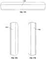
- FIG. 1is a perspective view of an example toilet seat assembly configured to communicate with a controller, the toilet seat assembly having a seat base and a lid;
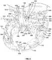
- FIG. 2is a perspective view of the toilet seat assembly of FIG. 1 with a housing of the seat base removed to show internal components of the seat base including a washing apparatus, a drying apparatus, and a spray canister device;
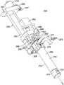
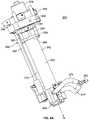
- FIG. 3is a perspective view of the toilet seat assembly of FIG. 2 with various internal components removed to show the washing apparatus having a spray wand, a collar shroud, and a motor, the washing apparatus coupled to a water reservoir and a cleanser reservoir via tubing;
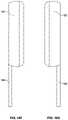
- FIG. 4Ais a perspective view of the washing apparatus of FIG. 3 isolated from the toilet seat assembly and showing the spray wand, the collar shroud, and a motor, wherein the spray wand is in a retracted position;
- FIG. 4Bis a perspective view of the washing apparatus similar to FIG. 4A showing the spray wand in an extended position to spray one or more liquid products from a nozzle thereof;
- FIG. 5is a close-up perspective view of the spray wand showing a body portion and a head portion thereof, the head portion having a nozzle for delivering one or more liquid products to the perineal region of a user;
- FIG. 6is a perspective view of the collar shroud of the washing apparatus showing apertures for receiving bactericidal light sources therein, a bracket for positioning the collar shroud in the toilet seat assembly, and apertures for fluidic coupling to the water reservoir;
- FIG. 7is a close-up perspective view of the collar shroud of FIG. 6 surrounding the spray wand of FIG. 5 , the apertures of the collar shroud having bactericidal light sources placed therein for shining bactericidal light on the spray wand;
- FIG. 8Ais a close-up perspective view of the collar shroud of the washing apparatus of FIG. 1 showing a power circuit board for powering the bactericidal light sources positioned on the collar shroud and electrically connected to the bactericidal light sources;
- FIG. 8Bis a close-up perspective view similar to FIG. 8A of an opposite side of the collar shroud
- FIG. 9is an exploded view of an alternative embodiment of a collar shroud, the collar shroud including a single aperture for fluidic coupling to the water reservoir;
- FIG. 10is a partial perspective view of the washing apparatus of FIG. 2 shown positioned in the toilet seat assembly in a retracted position and showing the spray canister device positioned adjacent the washing apparatus;
- FIG. 11is a partial perspective view of the toilet seat assembly of FIG. 1 showing the spray wand extending from an aperture of the seat base for delivering a liquid product to the perineal region of a user;
- FIG. 12is a perspective view of the toilet seat assembly of FIG. 2 with various internal components removed to show the drying apparatus having a fan, an elongate conduit, and a heating unit;
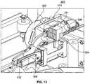
- FIG. 13is a partial perspective cut-away view with a portion of the elongate conduit removed to show the heating unit of the drying assembly positioned in the elongate conduit for heating the air produced by the fan;
- FIG. 14is a perspective view of the toilet seat assembly of FIG. 2 with various internal components removed to show the spray canister device having a spray canister, a canister housing, a tray, a chassis, and a motor;
- FIG. 15is a partial perspective view of a rear portion of the housing of the toilet seat assembly of FIG. 1 with the maintenance cover removed to show an aperture for installing the spray canister and canister housing, a valve for refilling the cleanser assembly, and a service button;
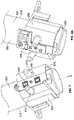
- FIG. 16Ais a front elevational view of a controller associated with the toilet seat assembly to control operation thereof, the controller including a flip cover;
- FIG. 16Bis a front elevational view of the controller of FIG. 16A showing the flip cover in an open position revealing additional buttons for controlling the toilet seat assembly;
- FIG. 16Cis top-side plan view of the controller of FIG. 16A ;
- FIG. 16Dis a right-side elevational view of the controller of FIG. 16A ;
- FIG. 16Eis a left-side elevational view of the controller of FIG. 16A ;
- FIG. 16Fis a view similar to FIG. 16D with the flip cover of the controller in the open position;
- FIG. 16Gis a view similar to FIG. 16E with the flip cover of the controller in the open position;
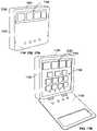
- FIG. 17Ais a perspective view of an alternative embodiment of a controller associated with a toilet seat assembly, the controller including a flip cover;
- FIG. 17Bis a perspective view of the controller of FIG. 17A with the flip cover in an open position;
- FIG. 17Cis top-side plan view of the controller of FIG. 17A ;
- FIG. 17Dis a right-side elevational view of the controller of FIG. 17A ;
- FIG. 17Eis a left-side elevational view of the controller of FIG. 17A ;
- FIG. 18is a schematic diagram of the controller, a control unit of the toilet seat assembly, and example components of the toilet seat assembly that the control unit is configured to control;
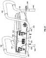
- FIG. 19is a partial perspective view of a rear side of the toilet seat assembly of FIG. 1 showing a bracket assembly coupled to a portion thereof, the bracket assembly including threaded fasteners to attach the toilet seat assembly to an existing toilet bowl structure;
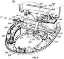
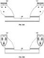
- FIG. 20Ais a perspective view of the bracket assembly of FIG. 17 removed from the toilet seat assembly, the bracket assembly including a base plate having a flat portion and a sleeve portion for receiving one or more grab bars, an arm plate having a base portion and two arms, and a pair of hinges each having an adjusting portion and a mounting portion;
- FIG. 20Bis a perspective view of an opposite side of the bracket assembly of FIG. 20A showing slots of the base portion of the arm plate for adjusting the positioning of the toilet seat assembly;
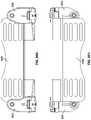
- FIG. 20Cis a front-side elevational view of the bracket assembly of FIG. 20A not including the base plate;
- FIG. 20Dis a rear-side elevational view of the bracket assembly of FIG. 20A not including the base plate;
- FIG. 20Eis a left-side elevational view of the bracket assembly of FIG. 20A not including the base plate;
- FIG. 20Fis a right-side elevational view of the bracket assembly of FIG. 20A not including the base plate;
- FIG. 20Gis a top-side plan view of the bracket assembly of FIG. 20A not including the base plate;
- FIG. 20His a bottom-side plan view of the bracket assembly of FIG. 20A not including the base plate;
- FIG. 21is a perspective view of the rear side of the toilet seat assembly with the bracket assembly attached and a pair of grab bars coupled thereto at a first end thereof for assisting individuals sit down on, and stand up from, the toilet seat assembly;
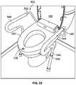
- FIG. 22is a perspective view of the toilet seat assembly including the grab bars, the grab bars having an adjustable second end depending on the height of the toilet seat assembly;
- FIG. 23is a schematic diagram of a method for disinfecting a spray wand after a cleaning operation of the toilet seat assembly.
- a toilet seat assemblyincluding a seat base and a seat lid, and further including a washing apparatus, a drying apparatus, and a spray canister device positioned in the seat base.
- a controller having a user interfaceis configured to communicate with a control unit of the toilet seat assembly to control operation of the components of the toilet seat assembly, as discussed in further detail below. So configured, a user may operate the toilet seat assembly to clean the user's perineal region via the washing apparatus, dry the user's perineal region via the drying apparatus, and spray the user's perineal region with one or more liquid products via the spray canister device.
- the toilet seat assemblyincludes a washing apparatus.
- the washing apparatusis positioned in the seat base and includes a spray wand fluidically coupled to a cleanser reservoir and a water reservoir, and collar shroud extending at least partially around an exterior surface the spray wand.
- the spray wandhas a body portion and a head portion with one or more nozzles and is configured to deliver water from the water reservoir and/or liquid from the cleanser reservoir through the one or more nozzles thereof.
- the collar shroud of the washing apparatusmay include one or more bactericidal light sources positioned proximate the spray wand such that the bactericidal light sources may shine bactericidal light on the spray wand to promote disinfection thereof.
- One or more motorsmay be operatively coupled to the washing apparatus, and one of the one or more motors may be configured to cause the spray wand to move between the retracted position and the extended position. Additionally, one of the one or more motors may be configured to rotate the head portion of the spray wand to deliver water and/or cleanser to the perineal region. In operation, the motors may be configured to extend and rotate the spray wand in response to the user interface of the controller receiving a user input.
- the collar shroudmay include one or more tubular apertures extending therethrough and permitting access to the exterior surface of the spray wand.
- the one or more apertures permitting access to the exterior surface of the spray wandmay be fluidically coupled to the water reservoir of the toilet seat assembly such that water may be delivered therefrom to the spray wand for rinsing and cleaning the exterior surface thereof.
- the toilet seat assemblyfurther includes a drying apparatus.
- the drying apparatusincludes a fan, a heating unit, and a conduit for delivering air from the fan to the perineal region of the user.
- the fanis configured to blow air through the conduit and the heating unit positioned therein to deliver the air after the perineal region has been washed with water and/or cleanser via the washing apparatus.
- the speed of the air or the temperature of the air delivered by the fanis configured to be adjusted by the controller associated with the toilet seat assembly.
- a spray canister deviceincluding a canister containing a liquid product, a canister housing having an opening, a chassis element, and a tray that is slidably coupled to the chassis element.
- the spray canister device and operation thereofare substantially disclosed in U.S. application Ser. No. 16/426,436, filed on May 30, 2019, which is incorporated herein by reference in its entirety.
- the spray canister devicemay be positioned in the toilet seat assembly such that the spray canister device may be used to apply a liquid product to the perineal region of a user.
- a motorcontrolled by the control unit of the toilet seat assembly, may be operatively coupled to the tray to slidably move the tray between a retracted position within the toilet seat assembly and an extended position extending outward from an opening in the toilet seat assembly. So configured, the canister housing and canister positioned therein may be moved with the tray between the retracted position and the extended position such that the liquid product may be sprayed onto the perineal region of a user.
- the spray canister devicemay be configured to spray the liquid product after the perineal region of the user has been washed and dried by the washing apparatus and the drying apparatus, respectively.
- the controller associated with the toilet seat assemblyis configured to control operation of the components included in the toilet seat assembly.
- the controllerincludes a user interface for receiving a user input, a processor or control circuit, communication circuitry, and a memory.
- the processor of the controllerupon receiving the user input at the user interface, is configured to cause the communication circuitry to communicate a control signal to the control unit of the toilet seat assembly to cause operation of a component thereof.
- the controllermay communicate a control signal configured to cause the motor of the washing apparatus to move the spray wand to the extended position for delivering the water and/or cleanser to the perineal region of the user.
- the usermay adjust various features of the toilet seat assembly via the user interface of the controller such as, for example, the temperature of the water in the water reservoir, the speed and temperature of the air from the drying apparatus, among others as discussed in further detail below.
- the toilet seat assemblymay further include an auxiliary user interface coupled to the control unit to operate the toilet seat assembly.
- the auxiliary user interface coupled to the control unitis in the form of a piezoelectric button positioned on the housing of the seat base for convenient access by a user.
- the example toilet seat assemblymay further include a bracket assembly for securing the toilet seat assembly to an existing toilet bowl and water tank structure.
- a seat and lid of the existing toilet bowlmay be removed, and the toilet seat assembly may be affixed on the existing toilet bowl via the bracket assembly.
- the bracket assemblymay include a base plate, an arm plate, and a pair of hinges for attaching the toilet seat assembly to the existing toilet bowl and water tank.
- the bracket assemblymay only include the arm plate and the hinges.
- the base plate, arm plate, and hingeseach include means for adjustment depending on the size of the existing toilet bowl such that the toilet bowl assembly may be affixed to a plurality of different sized toilet bowl and water tank structures.
- the base plate, arm plate, and hingesmay include slots to be aligned depending on the size and height of the selected toilet bowl.
- the base platemay include a sleeve portion configured for attachment to one or more grab bars to be positioned proximate the toilet bowl assembly to facilitate standing up from and sitting down on the toilet seat assembly for the user.
- a toilet seat assembly 100including a seat base 102 having a base portion 103 and a housing 104 coupled thereto, and further including a lid 106 with a plurality of supports 107 .
- a power cord 110having a wall connector 112 for connection to a standard wall outlet, such as a ground fault circuit interrupter (GFCI) outlet, is shown extending from the toilet seat assembly 100 and is configured to supply power to the components of the toilet seat assembly 100 .
- GFCIground fault circuit interrupter
- a washing apparatus 200 , a drying apparatus 300 , and a spray canister device 400are positioned in the seat base 102 of the toilet seat assembly 100 .
- a controller 150in the form of remote control 152 , is shown associated with the toilet seat assembly 100 and configured to control operation thereof via a user interface 154 .
- a maintenance cover 114is positioned on a back portion 116 of the housing 104 in a closed position covering one or more apertures (shown in FIG. 14 ) for servicing components of the toilet seat assembly 100 .
- Each component of the toilet seat assembly 100will be discussed in turn below.
- the housing 104 of the seat base 102may be shaped and contoured for comfort of the user.
- the housing 104may be sloped at an angle to facilitate and assist individuals with mobility impairments in sitting down on, and standing up from, the toilet seat assembly 100 .
- the seat base 102may be angled downward toward the front thereof.
- various electrical componentsare positioned in the seat base 102 of the toilet seat assembly 100 .
- the housing 104 and base portion 103 that comprise the seat base 102may be coupled together such that the housing 104 overlaps an edge of the seat base portion 103 .
- a seal(not shown) may be included that is positioned between the housing 104 and the base portion 103 , such as a rubber gasket, to insulate the seat base 102 from water or bodily fluids.
- a handle 118may be positioned on a side of the housing 104 to facilitate standing up from, and sitting down on, the toilet seat assembly 100 .
- the seat base 102may be formed of a polycarbonate and polybutylene terephthalate (PC-PBT) composition for ease of cleaning.
- the seat base 102may be formed of other plastics or resins typically used in both acute and post-acute care settings.
- the lid 106 and other components of the toilet seat assembly 100such as the maintenance cover 114 , may also be formed of a plastic or resin material to promote ease of cleaning and ease of disinfection.
- the lid 106 and other componentsmay also be formed of a polycarbonate and polybutylene terephthalate (PC-PBT) composition.
- the lid 106includes supports 107 in the form of six reinforced rib members 108 on an interior surface 120 thereof such that the rib members 108 support the lid 106 when the lid 106 is in a closed position proximate the housing 104 of the seat base 102 .
- the lid 106may include any number of reinforced rib members 108 .
- the supports 107may alternatively be formed as support posts, wedges, and ridges, among other structures that are configured to support the lid 106 . So configured, when the lid 106 is in the closed position the user may sit on the lid with enhanced support such that there is a lower risk of the lid 106 breaking, bending, or otherwise buckling under the weight of the user.
- the lid 106is made of a resilient, durable plastic or resin material to promote enhanced rigidity.
- the toilet seat assembly 100is configured to support a user of up to 325 lbs. when the lid is in the closed position. Further, the toilet seat assembly 100 , in some configurations, is configured to support a user of up to 325 lbs. in both the lid closed and lid open positions.
- FIG. 2shows the toilet seat assembly of FIG. 1 with the housing 104 of the seat base 102 removed to reveal the internal components of the toilet seat assembly 100 including, for example, the washing apparatus 200 , the drying apparatus 300 , and the spray canister device 400 .
- the washing apparatus 200includes a spray wand 202 that is fluidically coupled to a water reservoir 204 and a cleanser reservoir 206 for delivering water and/or cleanser to the perineal region of a user. Due to the number of components positioned in the seat base 102 , for ease of illustration, the fluidic connections (e.g., plastic or rubber tubing) between the components of the washing apparatus 200 are not shown in FIG. 2 and can instead be seen in more detail in FIG. 3 .
- the fluidic connectionse.g., plastic or rubber tubing
- the washing apparatus 200may include a collar shroud 208 extending around at least a portion of an exterior surface 210 of the spray wand 202 .
- the collar shroud 208includes one or more bactericidal light sources (shown in FIG. 7 ) for disinfecting the spray wand 202 after the perineal region of the user has been sprayed with the water and/or cleanser, as discussed in further detail below.
- the collar shroud 208may include one or more apertures (i.e., apertures 212 , 212 ′ shown in FIG. 6 ) through a sidewall 214 thereof permitting access to the exterior surface 210 of the spray wand 202 such that water may be delivered through the apertures 212 , 212 ′ to rinse the spray wand 202 after a cleaning operation.
- the spray wand 202is coupled to a motor 216 , and the motor 216 is configured to move the spray wand 202 between a retracted position (i.e., positioned in the seat base 102 of the toilet seat assembly 100 ) and an extended position (i.e., extending out of the seat base 102 of the toilet seat assembly 100 ).
- a retracted positioni.e., positioned in the seat base 102 of the toilet seat assembly 100
- an extended positioni.e., extending out of the seat base 102 of the toilet seat assembly 100 .
- one or more pumpssuch as water pump 218 , or cleanser pump 220
- the spray wand 202in some configurations, is coupled to an auxiliary motor, as described below, for rotating the spray wand 202 .
- the example drying apparatus 300 seen in FIG. 2includes a fan 302 , a heating unit 304 (shown in FIG. 12 ), and a conduit 306 .
- One end of the conduit 306may be covered by a drying cover 308 .
- the fan 302is configured to blow air through the conduit 306 , and through the heating unit 304 positioned therein, to deliver the air to the perineal region of the user after the perineal region has been washed with water and/or cleanser via the washing apparatus 200 .
- the speed of the air delivered by the fan 302 or the temperature of the airmay be adjusted by the user via a user interface 154 of the controller 150 .
- the spray canister device 400includes a canister 402 containing a liquid product, a canister housing 404 having an opening, a chassis element 406 , and a tray 408 slidably coupled to the chassis element 406 .
- the spray canister device 400is positioned in the toilet seat assembly 100 .
- a motor 410is operatively coupled to the tray 408 to slidably move the tray 408 between a retracted position within the seat base 102 and an extended position extending outward from an opening of the seat base 102 .
- the canister housing 404 and canister 402 positioned thereinmay be moved with the tray 408 between the retracted position and the extended position such that the liquid product may be sprayed onto the perineal region of a user, and thereafter, be retracted back to an initial position.
- the spray canister device 400may be configured to spray the liquid product after the perineal region of the user has been washed and dried by the washing apparatus 200 and the drying apparatus 300 , respectively.
- the spray canister device 400is configured to be operated via the controller 150 associated with the toilet seat assembly 100 .
- a power supply 122may be positioned in the seat base 102 that receives power from the power cord 110 and is coupled to a control unit 124 of the toilet seat assembly 100 .
- the control unit 124may include one or more circuit boards 126 , 128 for controlling the components of the toilet seat assembly 100 .
- circuit board 126may be a power circuit board including a power circuit
- circuit board 128may be a control circuit board including a control circuit.
- Circuit boards 126 , 128may be manufactured, for example, as printed circuit boards (PCBs) known in the art.
- the control unit 124may be configured to cause operation of the washing apparatus 200 to spray water and/or cleanser, cause operation of the drying apparatus 300 , and cause operation of the spray canister device 400 , as discussed in further detail below.
- the control unit 124may include a processor 130 and communication circuitry 132 (shown in FIG. 16 ) to receive communications from the controller 150 associated with the toilet seat assembly 100 , such as the remote control 152 . So configured, the user interface 154 of the controller 150 may receive a user input configured to cause the controller 150 to communicate a control signal to the control unit 124 to cause operation or adjustment of one of the components of the toilet seat assembly 100 .
- a sensor 134may be placed proximate the seat base 102 to determine whether a user is present on the toilet seat assembly 100 .
- the sensor 134may be positioned behind a window 136 made of translucent material such as glass or thin plastic such that the sensor 134 may detect when a user is present.
- the sensor 134may be an infrared sensor, a photoelectric sensor, or an ultrasonic sensor coupled to the control unit 124 of the toilet seat assembly 100 .
- the sensor 134may, for example, inhibit the control unit 124 from operating the washing apparatus 200 such that water and/or cleanser is not sprayed from the toilet seat assembly 100 into a surrounding area when a user is not present.
- a pressure sensor(not shown) may be incorporated into the housing 104 of the seat base 102 to assess presence of a user.
- the toilet seat assembly 100may further include a speaker (not shown) configured to emit sound upon, for example, the toilet seat assembly 100 completing a cleaning and/or drying operation.
- the speakermay be coupled to or integrated with the controller 150 to generate sound therefrom.
- the speakermay be positioned proximate the housing 104 of the seat base 102 .
- the volume of the speakermay be adjusted via the controller 150 associated with the toilet seat assembly 100 .
- the speakermay be configured to connect with a mobile communication device of the user (e.g., a cellular phone or smart phone) via a wireless short-range communication protocol such as, for example, Bluetooth, to play audio selected by the user.
- a mobile communication device of the usere.g., a cellular phone or smart phone
- a wireless short-range communication protocolsuch as, for example, Bluetooth
- the toilet seat assembly 100may additionally include a light source (not shown) positioned proximate the housing 104 of the seat base 102 to illuminate portions thereof.
- the light sourcemay be turned on or off via the controller 150 , and may be desirable for using and/or cleaning the toilet seat assembly 100 in a dimly lit area.
- an auxiliary user interface 138 communicatively coupled with the controller 150 and/or control unit 124may be included.
- the auxiliary user interface 138may be positioned proximate a surface of the housing 104 of the seat base 102 for convenient access.
- the auxiliary user interface 138is in the form of a piezoelectric button 140 .
- the piezoelectric button 140may be mechanically sealed (e.g., using a flexible film or plastic) to inhibit ingress of water or bodily fluids in the interior of the seat base 102 .
- the auxiliary user interface 138is positioned on a front portion 142 of the housing 104 for convenient access to an individual using the toilet seat assembly 100 (e.g., between where the user's legs would be positioned).
- the auxiliary user interface 138may be actuated multiple times to activate different features of the toilet seat assembly 100 . For example, one touch may cause the toilet seat assembly 100 to operate the spray wand 202 to clean the perineal region of a user, and two presses may cause both washing and drying operations.
- the usermay program a specified order of operations to occur in response to the auxiliary user interface 138 receiving a user input. For example, the user may select that only operation of the washing apparatus 200 and drying apparatus 300 occur upon the auxiliary user interface 138 receiving the user input. So configured, both the user interface 154 of the controller 150 and the auxiliary user interface 138 may be used to operate the toilet seat assembly 100 .
- the auxiliary user interface 138may include one or more indicators, such as in the form of LED 144 , that are configured to indicate various operating conditions to a user.
- the indicatoris an LED 144
- illumination of the LED 144could indicate the end of a cleaning operation via a blue light or the LED 144 could indicate an error in the toilet seat assembly 100 , such as a broken component, via an amber-colored light.
- any colormay be selected to indicate different information to the user.
- the toilet seat assembly 100includes a seat base heater (not shown) positioned in the interior of the seat base 102 to heat the surface of the housing 104 .
- a seat base heater(not shown) positioned in the interior of the seat base 102 to heat the surface of the housing 104 .
- the seat base heatermay be controlled by the controller 150 associated with the toilet seat assembly 100 , and additionally, may include various heating settings such as low, medium, and high depending on user preference that may be selected at the user interface 154 of the controller 150 .
- the washing apparatus 200will be discussed in more detail with respect to FIGS. 3-11 .
- the washing apparatus 200includes the spray wand 202 and the collar shroud 208 extending around the exterior surface 210 of the spray wand 202 .
- a motor 216is coupled to the spray wand 202 and is configured to move the spray wand 202 between a retracted position and an extended position for delivering water and/or cleanser to the perineal region of the user.
- the spray wand 202is in transit between the retracted position (i.e., inside the seat base 102 ) and the extended position (i.e., outside the seat base 102 ) with a head portion 224 thereof extending partially out of the seat base 102 of the toilet seat assembly 100 .
- the motor 216may cause the spray wand 202 to extend out of the seat base 102 of the toilet seat assembly 100 to deliver water and/or cleanser to the perineal region of a user, as discussed in further detail below.
- the spray wand 202may be configured to stop at different predetermined points between the retracted position and the extended position.
- the spray wand 202may be configured to extend about 10 mm to about 50 mm out of the seat base 102 . In other forms, the spray wand 202 may be extended even further out of the seat base 102 of the toilet seat assembly 100 . In some forms, the spray wand 202 may be made of stainless steel to inhibit germ or bacteria growth thereon.
- the controller 150 of the toilet seat assembly 100may be configured to operate the washing apparatus 200 .
- the controller 150may be configured to cause the motor 216 coupled to the spray wand 202 to move the spray wand 202 to the extended position.
- the user inputmay cause rotation of the spray wand 202 by either motor 216 or another, separate motor, as described below. So configured, the controller 150 may cause the spray wand 202 to move between the retracted and extended positions and rotate the spray wand 202 to deliver the water and/or cleanser to precise areas of the perineal region.
- the usermay also program selected spray patterns of the spray wand 202 depending on a desired coverage of the perineal region via the user interface 154 of the controller 150 . Additionally, the user may select a water time (e.g., an amount of time the spray wand 202 will spray the water and/or cleanser) via the user interface 154 of the controller 150 . Such features may be programmed and stored in a memory of the controller 150 , as described further with respect to FIGS. 16A and 16B .
- the water reservoir 204 and the cleanser reservoir 206are shown positioned in the seat base 102 of the toilet seat assembly 100 .
- the water reservoir 204is configured to contain an amount of water and the cleanser reservoir 206 is configured to contain an amount of cleanser or other liquid product.
- the water reservoir 204may be configured to contain between about 600 and 605 cubic centimeters of water and the cleanser reservoir 206 may be configured to contain between about 300 and 350 cubic centimeters of cleanser.
- Both the water reservoir 204 and the cleanser reservoir 206may be fluidically coupled to the spray wand via tubes, channels, or like such that either water and/or cleanser may be delivered to the perineal region of the user via the nozzle 222 of the spray wand 202 .
- the head portion 224 of the spray wand 202may include two separate nozzles with one nozzle fluidically coupled to, and configured to deliver the water from, the water reservoir 204 and the other nozzle fluidically coupled to, and configured to deliver the cleanser from, the cleanser reservoir 206 .
- both the water reservoir 204 and the cleanser reservoir 206are operatively coupled to the water pump 218 and the cleanser pump 220 , respectively, to pump the respective liquid from each reservoir 204 , 206 to the spray wand 202 of the washing apparatus 200 .
- the water reservoir 204 and water pump 218are configured to dispense between about 600 mL to about 800 mL per minute. In another illustrative embodiment, the water reservoir 204 and water pump 218 dispense about 605 mL to about 750 mL per minute.
- the cleanser or other liquid product to be contained in the cleanser reservoirmay include, for example, an amount of water, aloe-vera, moisturizers, deodorizers, vitamins, fragrance, cocamidopropyl betaine, lauryl sulphate, diazolidinyl urea, methylparaben propylene glycol, citric acid, among other ingredients.
- a water inlet 226is shown positioned adjacent to the power cord 110 and is configured to be coupled to an exterior water source, such as existing plumbing in a bathroom where the toilet seat assembly 100 is located.
- the water inlet 226may be coupled directly to the water reservoir 204 such that water from the water inlet 226 will continually fill the water reservoir 204 for operation of the washing apparatus 200 .
- the water inlet 226may be coupled to a water regulator (not shown) positioned in the toilet seat assembly 100 which is in turn coupled to the water reservoir 204 .
- the water regulatoris configured to decrease the water pressure of the water coming in through the water inlet 226 such that the water does not flow into the water reservoir 204 at too high a pressure that could rupture any fluidic connections, overfill the water reservoir 204 , or otherwise damage the components of the toilet seat assembly 100 .
- the water reservoir 204is connected to the water pump 218 via tube 228 and the water reservoir 204 is further connected to the spray wand via tube 230 .
- a diverter valve(not shown) may be included such that the water from the water reservoir 204 may be supplied to both the spray wand 202 and the apertures 212 , 212 ′ of the collar shroud 208 for rinsing the spray wand 202 .
- the water in the water reservoir 204may be received through the water inlet 226 , flow to the water reservoir 204 through a tube 232 , and thereafter be pumped via pump 218 to the spray wand through tube 230 and/or the apertures 212 , 212 ′ of the collar shroud 208 through tube 234 .
- the water reservoir 204may further include a heater (not shown) such that the temperature of the water within the water reservoir 204 may be regulated by the user.
- a heatersuch that the temperature of the water within the water reservoir 204 may be regulated by the user.
- an immersion heatermay be used to heat the water contained in the water reservoir 204 to a desired temperature.
- a usermay desire that warmer or colder water be used to perform a cleaning operation with the washing apparatus 200 and the temperature may be adjusted via the user interface 154 of the controller 150 .
- the user interface 154may provide the user with temperature options such as low, medium, and high.
- the user interface 154may include a sliding scale or dial to precisely select the temperature of the water in the water reservoir 204 .
- a thermistor 236may be incorporated in a circuit configured to control the heater and may be used to inhibit the washing apparatus 200 from spraying the water through the spray wand 202 when the temperature of the water rises above a threshold determined at least in part by the resistance value of the thermistor 236 .
- the cleanser reservoir 206is fluidically connected to the cleanser pump 220 via tube 238 and is further connected to the spray wand 202 via tube 240 .
- the cleanser in the cleanser reservoir 206may be pumped via the cleanser pump 220 to the spray wand 202 to deliver the cleanser to the perineal region of the user through the nozzle 222 thereof.
- the cleansermay be delivered through a separate nozzle positioned on the head portion 224 of the spray wand 202 .
- the cleanser reservoir 206includes a valve 242 positioned at a top side 244 thereof for receiving additional cleanser.
- the maintenance cover 114covers the valve 242 for refilling when the maintenance cover 114 is in the closed position.
- the valve 242may include a keyed connection such that a fill bottle containing additional cleanser requires a corresponding lid to depress the valve 242 and refill the cleanser reservoir.
- the valve 242may include a spring (not shown) to continually bias the valve 242 into a closed position. Upon depression of the valve 242 via the lid of the fill bottle, the cleanser contained therein may flow into the cleanser reservoir 206 to refill the reservoir 206 with cleanser or other liquid product.
- this pressure activated configurationinhibits any potential spilling of the cleanser for older, less dexterous users. Additionally, no manipulation of the fill bottle is required once the lid of the fill bottle has been matingly coupled to the valve 242 (e.g., no squeezing or manipulation of the fill bottle is required to cause flow of the cleanser from the fill bottle to the cleanser reservoir 206 ).
- both the water reservoir 204 and the cleanser reservoir 206may include a sensor (not shown), such as a float switch, to detect when the level of liquid contained therein drops below a predetermined threshold.
- a sensorsuch as a float switch
- Each sensormay be coupled to an indicator associated with the toilet seat assembly 100 to indicate when a level of liquid therein is low and in need of replacement.
- each sensormay be coupled to the LED 144 of the piezoelectric button 140 or an LED on the controller 150 such that when the sensor detects that the level of cleanser/water is low, the LED 144 or LED on the controller 150 will be illuminated to indicate the same to a user.
- different colored LEDsmay be used for each sensor such that one color may indicate that the liquid in the water reservoir 204 is low and another color may indicate that the liquid in the cleanser reservoir 206 is low.
- the sensorsmay be communicatively coupled to the user interface 154 of the controller 150 to indicate to a user on, for example, a screen thereof that the level of water and/or cleanser is low.
- the water reservoir 204may be continuously refilled via water from the water inlet 226 without requiring any user input. For example, upon the sensor detecting that the level of water is the water reservoir 204 is below a certain threshold, the control unit 124 of the toilet seat assembly 100 may control a valve (not shown) of the water inlet 226 to cause more water to flow into the water reservoir 204 to refill the water reservoir 204 .
- FIGS. 4A and 4Bshow the spray wand 202 in the retracted position and the extended position, respectively.
- the one or more motorsare configured to move the spray wand 202 between the positions shown in FIGS. 4A and 4B to deliver the water and/or cleanser to the perineal region of the user.
- the spray wand 202is advanced out of the seat base 102 , through the collar member 208 .
- the washing apparatus 200includes one or more motors such as motor 216 .
- motor 216is configured to cause the spray wand to move between the retracted position (seen in FIG. 4A ) and the extended position (seen in FIG. 4B ).
- the motor 216may be mounted in the toilet seat assembly 100 via motor mount 246 .
- the motor 216may be a stepper motor.
- the motor 216is configured to cause a slide plate 248 connected to the spray wand 202 to advance in a direction A.
- the spray wand 202 coupled theretois advanced out of the seat base 102 of the toilet seat assembly 100 in direction A towards the extended position.
- a guide 250such as in the form of elongate rod 252 may be provided such that the slide plate 248 may slide along the guide 250 on a track to inhibit the spray wand 202 from moving in an undesirable direction during operation.
- the washing apparatus 200may further include a force sensor 245 as shown in FIG. 4B having an actuator 247 connected thereto.
- the slide plate 248may contact and depress the actuator 247 to indicate that the spray wand 202 has been fully retracted.
- the force sensor 245may trigger rinsing of the spray wand 202 and illumination of the bactericidal light sources 276 of the collar shroud 208 as described below.
- the slide plate 248 described abovemay additionally be coupled to a rotational adapter 254 configured to rotate the spray wand 112 via a second motor, such as motor 256 shown in FIG. 4B .
- the rotational adapter 254is coupled to a flange 258 via spacers 260 , 260 ′, and the flange 258 is in turn coupled to a body portion 262 of the spray wand 202 at an end 264 thereof.
- the spacers 260 , 260 ′are typically used to provide spacing between the rotational adapter 254 and the flange 258 to accommodate the fluidic connections between the spray wand 202 and the water and cleanser reservoirs 204 , 206 .
- the tube 230 from the water reservoir 204 and tube 240 from the cleanser reservoir 206deliver the water and cleanser respectively to the spray wand 202 in the space between the flange 258 and the rotational adapter 254 created by the spacers 260 , 260 ′.
- the rotational adapter 254is configured to be rotated by, for example, motor 256 shown in FIG. 4B .
- a single motormay be configured with multiple gearings such that the single motor may be configured for both moving the spray wand 202 between the retracted position and the extended position and rotating the spray wand 202 .
- the controller 150 associated with the toilet seat assembly 100is configured to cause operation of the one or more motors to move and rotate the spray wand 202 of the washing apparatus 200 to deliver the water and/or cleanser.
- FIGS. 5 and 6show close-up isolated views of the spray wand 202 and the collar shroud 208 , respectively.
- the spray wand 202includes a body portion 262 and a head portion 262 .
- the spray wand 202includes an exterior surface 210 .
- the head portion 224 of the spray wand 202has a top surface 266 .
- the nozzle 222is positioned on the head portion 224 of the spray wand 202 such that water and/or cleanser may be sprayed therefrom on the perineal region of the user.
- the head portion 224 of the spray wand 202may include multiple nozzles for delivering separate liquid products, such as water and cleanser.
- the collar shroud 208is formed as a generally annular structure having an opening 268 therethrough corresponding with the shape of, and configured to accommodate, the spray wand 202 .
- the collar shroud 208includes a bracket portion 270 for mounting the collar shroud 208 in the seat base 102 of the toilet seat assembly 100 .
- the collar shroud 208includes apertures 272 configured to receive bactericidal light sources (shown in FIG. 7 ) therein that may shine bactericidal light into the opening 268 where the spray wand 202 is positioned when the washing apparatus 200 is assembled.
- the collar shroud 208may further include apertures 212 , 212 ′ through a sidewall 214 thereof that are fluidically coupled to the water reservoir 204 .
- watermay be delivered through the apertures 212 , 212 ′, via the water pump 218 , to rinse off the spray wand 202 after a cleaning operation.
- the pair of apertures 212 , 212 ′are preferably spaced from one another such that both sides of the spray wand 202 may be rinsed with water.
- the single tube 234 from the water reservoir 204is coupled to a split valve 273 such that two separate tubes 274 , 274 ′ extend therefrom to deliver water to each aperture 212 , 212 ′, respectively.
- a bactericidal light source 276is positioned in each of the apertures 272 to illuminate the spray wand 202 with bactericidal light.
- the bactericidal lights sources 276may be LEDs such as chip-on-board LEDs.
- Bactericidal light sources 276should be understood to be light sources configured to produce light known for its bactericidal or disinfecting properties.
- the bactericidal lightis ultraviolet (UV) light and the bactericidal light sources 276 are UV LEDs.
- the bactericidal lightis any light having a wavelength between about 405 nm to about 470 nm.
- the two bactericidal light sources 276 in FIG. 7are aligned in the direction A.
- the apertures 272 to receive the bactericidal light sources 276may be positioned in other configurations.
- the apertures 272may be spaced from one another and extend radially about the inner, annular sidewall 278 of the collar shroud 208 .
- the bactericidal light sources 276may instead be positioned in another structure in the toilet seat assembly 100 proximate the spray wand 202 .
- a disinfecting operation of the spray wand 202will now be described below.
- the spray wand 202is extended to deliver water and/or cleanser to the perineal region of the user, there is a possibility that either urine, excrement, or other bodily fluids may inadvertently be splashed onto the exterior surface 210 of the spray wand 202 .
- the water pump 218may pump water from the water reservoir 204 to the apertures 212 , 212 ′ of the collar shroud 208 through tube 234 to rinse the spray wand 202 .
- the bactericidal light sources 276may then illuminate the exterior surface 210 of the spray wand 202 with bactericidal light to promote disinfection of the spray wand 202 . So configured, the collar shroud 208 promotes hygienic usage of the toilet seat assembly 100 .
- FIGS. 8A and 8Bshow similar views to FIG. 7 of the collar shroud 208 positioned surrounding the exterior surface 210 of the spray wand 202 , with the collar shroud 208 including a power circuit 280 that is electrically coupled to the bactericidal light sources 276 via wires, connectors, traces or the like.
- the power circuit board 280includes a power circuit that is configured to be closed to provide power to the bactericidal light sources 276 to shine the bactericidal light. So configured, the bactericidal light may be shined on the head portion 224 of the spray wand 202 including the nozzle 222 , the body portion 262 , or both the head and body portions 224 , 262 .
- the power circuitmay be configured to be closed to power the bactericidal light sources 276 upon the spray wand 202 returning to the retracted position. In other words, illumination of the bactericidal light sources 276 may be triggered once a cleaning operation is completed.
- the power circuit board 280 of the collar shroud 208is electrically coupled to the control unit 124 of the toilet seat assembly 100 such that the bactericidal light sources 276 of the collar shroud 208 may be controlled by the control unit 124 .
- the bactericidal light sources 276may illuminate the spray wand 202 with bactericidal light for a predetermined period of time after each cleaning operation of the toilet seat assembly 100 . For example, upon the spray wand 202 returning to the retracted position, the bactericidal light sources 276 may be activated for a period of about 2 minutes to illuminate the exterior surface of the spray wand 202 . In other forms, the bactericidal light sources 276 may be activated for a period of time between about 1 minute and about 3 minutes.
- actuation of the actuator 247 of the force sensor 245may be configured to trigger illumination of the bactericidal light sources 276 .
- the force sensor 245may be electrically coupled to the power circuit board 280 of the collar shroud 208 via wires, connectors, traces, or the like such that actuation of the actuator 247 is configured to close the power circuit of the power circuit board 280 to power the bactericidal light sources 276 for a predetermined period of time.
- the collar shroud 208is configured to shine bactericidal light on the spray wand 202 , such as, after each cleaning operation, to extend the spray wand 202 , spray the water and/or cleanser, and retract the spray wand 202 .
- the collar shroud 1208includes an annular opening 1268 therethrough configured to receive the spray wand 202 . Similar to collar shroud 208 , the collar shroud 1208 includes one or more apertures 1272 configured to receive bactericidal light sources therein. As shown, the apertures 1272 are of an annular shape such that the bactericidal light sources positioned therein have a corresponding annular shape.
- the collar shroud 1208may also include a bracket portion 1270 to mount the collar shroud 1208 within the seat base 102 of the toilet seat assembly 100 .
- the collar shroud 1208includes a single aperture 1212 configured to be fluidically coupled to the water reservoir 204 such that water from the water reservoir 204 may be pumped through the aperture 1212 to rise the exterior surface 210 of the spray wand 202 positioned in the aperture 1268 .
- the collar shroud 1208likewise includes a power circuit board 1280 , and additionally may include a window portion 1271 that is placed between the bactericidal light sources positioned in apertures 1272 and the power circuit board 1280 such that water is inhibited from splashing on the power circuit board 1280 when water is pumped through the aperture 1212 .
- FIG. 10shows a perspective view of the washing apparatus 200 positioned in the toilet seat assembly 100 .
- the seat base 102includes an aperture 156 through base portion 103 to permit the spray wand 202 to extend and retract therethrough during a cleaning operation.
- the top surface 266 of the head portion 224 thereofis configured to remain flush with the surface of the seat base 102 such that there are no portions extending outward from the seat base 102 .
- a covermay be used that is opened during a cleaning operation.
- the covermay be hingedly connected with the seat base 102 and additionally attached to the toilet seat assembly 100 with a spring such that the cover may be pushed to an open position when the motor 216 moves the spray wand 202 to the extended position, and the cover may be biased back via the spring into a closed position when the spray wand 202 is moved to the retracted position.
- FIG. 11shows the toilet seat assembly of FIG. 1 , including the base portion 103 and housing 104 of the seat base 102 , with the head portion 224 of the spray wand 202 extending from the aperture 156 to spray the perineal region of a user.
- the spray wand 202may be returned to the retracted position as shown, for example, in FIGS. 4A and 10 .
- the drying cover 308 described aboveis hingedly coupled to a portion of the seat base 102 and covers the second end 312 of the conduit 306 such that the pressure from the air will blow and hold open the dryer cover 308 while the air is being delivered therefrom.
- the drying apparatus 300is configured to be controlled by the controller 150 of the toilet seat assembly 100 .
- the controller 150may turn the fan 302 on or off, adjust the speed of the fan 302 , and adjust the temperature of the heating unit 304 depending on the user input received at the user interface 154 of the controller 150 .
- the usermay set a drying time period (i.e., a length of time the drying apparatus is blowing air) via the user interface 154 of the controller 150 .
- the spray canister devicewill be discussed in more detail with respect to FIGS. 14 and 15 .
- various other components of the toilet seat assembly 100 including the housing 104are removed to show the spray canister device 400 and the components connected thereto more clearly for simplicity and ease of explanation.
- the spray canister device for use in connection with the disclosed toilet seat assemblyis more fully disclosed in U.S. application Ser. No. 16/426,436, filed on May 30, 2019, the disclosure of which is incorporated herein by reference in its entirety.
- the spray canister device 400includes a canister 402 containing a liquid product, a canister housing 404 having an opening, a chassis element 406 , and a tray 408 slidably coupled to the chassis element 406 .
- a motor 410which may be operated by the controller 150 of the toilet seat assembly 100 , may be operatively coupled to the tray 408 to slidably move the tray 408 between a retracted position within the seat base 102 and an extended position extending outward from an opening in these seat base 102 .
- the canister housing 404 and canister 402 positioned thereinmay be moved with the tray 408 between the retracted position and the extended position such that the liquid product may be sprayed onto the perineal region of a user.
- the spray canister device 400may be configured to spray the liquid product after the perineal region of the user has been washed and dried by the washing apparatus 200 and the drying apparatus 300 , respectively.
- the liquid product configured to be delivered by the spray canister device 400may comprise, but is not limited to, one or more of skin protectants, ointments, creams, zinc oxide, calamine, barrier solutions, cleaning solutions, moisturizers, skin sealants, water, medicaments, cleaning solutions, among others.
- the liquid productis a barrier solution such that the barrier solution may be applied to the perineal region of a user to protect the user's skin and inhibit excessive moisture after cleaning via, for example, the washing apparatus 200 .
- FIG. 15shows the rear portion 116 of the housing 104 of the seat base 102 with the maintenance cover 114 removed to show multiple apertures thereunder.
- the maintenance cover 114is configured to be moved via a hinge or pivot point between a closed position and an open position. Underneath the maintenance cover 114 , there is an aperture 158 permitting access to the interior of the seat base 102 for installation and removal of the spray canister 402 and spray canister housing 404 .
- the aperture 158is shaped to facilitate insertion of the canister housing 404 and canister 402 in the seat base 102 for engagement with the tray 408 positioned therein.
- the aperture 158may be shaped to correspond with the shape of the canister housing 404 to only permit the canister housing 404 and canister 402 to be inserted in the seat base 102 in a desired orientation, thus simplifying the installation for the user.
- the cleanser valve 242 of the cleanser reservoir 206is also shown positioned in a recessed portion 160 of the housing 104 .
- the maintenance cover 114may be pivoted open and a fill bottle may be used to fill the reservoir 206 as described above.
- the toilet seat assembly 100may also include a service button 162 or switch as shown in FIG. 15 .
- the control unit 124 of the toilet seat assembly 100may perform one or more service operations including, for example, moving the spray wand 202 to the extended position for cleaning, illuminating bactericidal light on the spray wand 202 via the bactericidal light sources 276 , rinsing the spray wand 202 , among others.
- the controller 150 associated with the toilet seat assembly 100is provided for controlling various operations of the toilet seat assembly 100 .
- the controller 150is in the form of remote control 152 including various buttons, such as primary buttons 164 , for adjusting features of the toilet seat assembly 100 , and the controller 150 includes or is operatively coupled to user interface 154 .
- the controller 150may be, for example, a wall-mounted display including a touch screen, a mobile communication device (e.g., a cellular phone or smart phone), or any other remote control.
- the controller 150may be connected to the toilet seat assembly 100 via either a wireless or wired connection.
- the user interface 154 of the controller 150includes primary buttons 164 and secondary buttons 166 concealed by a cover, such as flip cover 168 configured to be pivoted open.
- the covercould be a sliding cover and may cover either the primary buttons 164 and the secondary buttons 166 , just the primary buttons 164 , or just the second buttons 166 .
- the controller 150may not include a cover.
- the primary buttons 164 and the secondary buttons 166may be positioned on a recessed portion of a front panel of the controller 150 such that the flip cover 168 , when in the closed position, covers the secondary buttons 166 and the surface of the flip cover 168 remains substantially flush with the front panel as shown in FIG. 16A .
- Each primary button 164may correspond with operation of the washing apparatus 200 , the drying apparatus 300 , and/or the spray canister device 400 .
- the secondary buttons 166may, for example, adjust the features of each component of the toilet seat assembly 100 as described respectively above, including adjusting the positioning of the spray wand 202 , the temperature of the water, the amount of liquid sprayed from the spray wand 202 , the temperature of heater for the seat base 102 , the temperature of the air blown by the drying apparatus 300 , turning the sound of the speaker on or off, and turning the light associated with the toilet seat assembly 100 on.
- Both the primary buttons 164 and the secondary buttons 166may include braille thereon to assist visually impaired users in operating the controller 150 .
- FIGS. 16C through 16Gshow various additional views of the controller 150 such as a top surface 180 , a right-side surface 181 , and a left-side surface 182
- the controller 150may additionally include one or more indicators or LEDs for conveying information regarding operation of the toilet seat assembly 100 to a user.
- the indicatormay be in the form of an LED similar to the LED 144 of the auxiliary user interface.
- the LED on the controller 150may be illuminated to indicate the same to the user.
- different colored LEDsmay be used for each sensor such that one color may indicate that the liquid in the water reservoir 204 is low and another color may indicate that the liquid in the cleanser reservoir 206 is low.
- the indicatormay be illuminated to indicate a problem or error in the system to the user.
- the flip cover 168may include apertures or window therethrough to visually indicate the indicator to a user.
- the indicatormay be in the form of a digital screen interface of the controller 150 .
- the screen interfacemay, for example, display a graphical representation of the amount of water and cleanser in the water and cleanser reservoirs 204 , 206 respectively.
- FIGS. 17A through 17EAn alternative embodiment of a controller 1150 is shown in FIGS. 17A through 17E .
- the controller 1150is shown including flip cover 1168 hingedly coupled to the controller 1150 and configured to cover one or more secondary buttons 1166 when the flip cover 1168 is in a closed position.
- the flip cover 1168is configured to cover the front surface of the controller 1150 and includes a window such that the primary buttons 1166 may be seen therethrough.
- the controller 1150further includes primary buttons 1164 that, upon actuation, may correspond with operation of the washing apparatus 200 , the drying apparatus 300 , and/or the spray canister device 400 .
- the controller 1150 and the controller 150are substantially similar in all respects, such as operation thereof, unless otherwise discussed herein.
- FIGS. 17C through 17Eshow various additional views of the controller 1150 such as a top surface 1180 , a right side surface 1181 , and a left-side surface 1182 .
- the controller 150further includes a processor 170 , communication circuitry 172 , and a memory 174 , and is configured to be programmed to store desired user settings.
- the usermay enter a “program” mode for one or more selected profiles to select the desired settings such as water temperature, air temperature, among others.
- the processor 170 of the controller 150may be configured to store the profiles in the memory 174 thereof such that different users of the toilet seat assembly 100 may utilize different settings depending on their profile.
- one usermay program a specific water and/or cleanser delivery pattern (e.g., the spray wand 202 extends, and rotates side-to-side while spraying as it is retracted to clean the user's perineal region with complete coverage).
- a specific water and/or cleanser delivery patterne.g., the spray wand 202 extends, and rotates side-to-side while spraying as it is retracted to clean the user's perineal region with complete coverage).
- the communication circuitry 172 of the controller 150is configured to communicate with the communication circuitry 132 of the control unit 124 in the toilet seat assembly 100 in order to control operation thereof.
- the communication circuitry 172 of the controller 150may be configured to communicate one or more control signals to the communication circuitry 132 of the control unit 124 to cause operation of the washing apparatus 200 , the drying apparatus 300 and/or the spray canister device 400 .
- the control unit 124is configured to cause operation of one or more of the washing apparatus 200 , the drying apparatus 300 , the spray canister device 400 , the water heater, the seat heater, the seat base light, among others via one or more control signals from the controller 150 .
- the usermay first select a water pattern, water time, water temp, and/or other desired settings via the secondary buttons 166 of the user interface 154 and then interact with a primary button 164 configured to cause operation of the washing apparatus 200 .
- the processor 170 of the controller 150(when the user interacts with the user interface 154 of the controller 150 ) is configured to cause the communication circuitry 172 to communicate a control signal to the control unit 124 of the toilet seat assembly 100 .
- the control unit 124is configured to cause operation of the washing apparatus 200 based at least in part on the selected settings of the user. So configured, the user may control each included aspect of the toilet seat assembly 100 via the controller 150 .
- the toilet seat assembly 100also optionally includes a bracket assembly 500 for attaching the toilet seat assembly 100 to an existing toilet bowl and water tank structure.
- a bracket assembly 500for attaching the toilet seat assembly 100 to an existing toilet bowl and water tank structure.
- the lid of an existing toilet bowlmay be removed, and the toilet seat assembly 100 may be affixed therein via the bracket assembly 500 , as described below.
- the bracket assembly 500is further configured to facilitate attachment to a grab bar assembly 502 for assisting individuals to either sit down on, or stand up from, the toilet seat assembly 100 .
- the bracket assembly 500may include hinges 504 for facilitating cleaning of an underside of the seat base 102 , as discussed in further detail below.
- FIG. 19shows the bracket assembly 500 attached to the rear portion 116 of the seat base 102 with the toilet bowl and water tank removed.
- the bracket assembly 500includes a base plate 506 , an arm plate 508 , and a pair of adjustable hinges 504 , 504 ′.
- the bracket assembly 500may be coupled to the seat base 102 of the toilet seat assembly 100 via threaded fasteners 510 , as shown in FIG. 2 .
- the threaded fastenersmay be, for example, screws, and may be secured to threaded apertures (not shown) positioned in the seat base 102 to couple the bracket assembly 500 to the toilet seat assembly 100 .
- the bracket assembly 500may be attached to an existing toilet bowl as described below.
- FIGS. 20A and 20Bshow perspective views of a front side and a back side of the bracket assembly 500 .
- the bracket assembly 500includes two hinges 504 , 504 ′.
- the bracket assembly 500may include more than two hinges.
- each hinge 504 , 504 ′has a mounting portion 512 and an adjusting portion 514 .
- Each mounting portion 512includes an aperture 516 to receive a threaded fastener 510 for coupling to a structure inside the seat base 102 as described above.
- Each adjusting portion 514includes one or more slots 518 configured to receive threaded fasteners 520 therethrough to secure the adjusting portion 514 to an arm 522 of the arm plate 508 . So configured, the adjusting portion 514 may be adjusted such that the threaded fasteners 520 are secured in a different portion of the one or more slots 518 to adjust the height of the bracket assembly 500 to facilitate attachment to different sized existing toilet bowls.
- the base plate 506typically includes a substantially flat portion 524 including one or more apertures for accepting threaded fasteners 526 (shown in FIG. 19 ) and a sleeve portion 528 extending from the flat portion 524 , the sleeve portion 528 having an aperture 530 extending therethrough along an axis parallel to a rear surface 532 of the seat base 102 .
- the sleeve portion 528 of the seat base 102includes apertures 534 therethrough, transverse the aperture 530 , at spaced intervals to receive threaded fasteners or biasing pins (not shown). The apertures 534 will be discussed in more detail with respect to FIG. 21 .
- the arm plate 508includes a base portion 536 configured to be positioned adjacent the flat portion 524 of the base plate 506 , and the arm plate 508 additionally includes two arms 522 , 522 ′.
- the base portion 536includes several slots 538 , similar to the adjusting portion 514 of the hinges 504 , 504 ′, to adjust the positioning of the bracket assembly 500 .
- the slots 538may be positioned such that the toilet seat assembly 100 may be placed in a desired position, and thereafter, the threaded fasteners 526 may be advanced therethrough and through apertures 540 of the flat portion 524 of the base plate 506 to secure the toilet seat assembly 100 to the toilet bowl.
- the arms 522 , 522 ′extend upward, and outward over the sleeve portion 528 of the base plate 506 such that the arms 522 , 522 ′ are supported thereon as shown in FIG. 20B .
- FIGS. 20C through 20Hshow additional example views of the bracket assembly 500 and do not include the base plate 506 .
- grab bar assembly 502 of the bracket assembly 500is shown including two elongate bars 542 , 542 ′ that may be coupled to the bracket assembly 500 in the sleeve portion 528 of the base plate 506 at first ends 543 thereof.
- the base plate 506may be included in the grab bar assembly 502 such that the bracket assembly 500 is usable to secure the toilet seat assembly to an existing toilet without the base plate 506 .
- the elongate bars 542 , 542 ′extend parallel to one another on the respective sides of the toilet seat assembly 100 such that an individual using the toilet seat assembly 100 can use the elongate bars 542 , 542 ′ to assist in standing up or sitting down.
- the elongate bars 542 , 542 ′may include a cover 544 on a portion thereof, such as a foam of soft plastic cover, to increase comfort for the user.
- the first ends 543 of the elongate bars 542 , 542 ′may include aperture (not shown) corresponding with the apertures 534 of the sleeve portion 528 of the base plate 506 such that a threaded fastener may be advanced therethrough to secure the grab bar assembly 502 to the bracket assembly 500 .
- the elongate bars 542 , 542 ′may include biasing pins that the user may press inwards for insertion into the sleeve portion 528 , slide the first end of the elongate bars 542 , 542 ′ into the sleeve portion 528 , and the biasing pins may bias up, via known means, upon reaching one of the apertures 534 to lock the grab bar assembly 502 into place.
- a second end 546 of the elongate bars 542 , 542 ′extends downwards towards the ground near the toilet seat assembly 100 as shown in FIG. 22 .
- the second end 546 of the elongate bars 542 , 542 ′may include an adjustment feature such that the grab bar assembly 502 may be installed on existing toilets of varying heights.
- an adjustment featurecould include a telescoping sleeve 548 surrounding the second end 546 of the elongate grab bars 542 , 542 ′ and configured to lock in place at predetermined points such that the grab bar assembly 502 contacts the ground to provide a sturdy and secure hold.
- a schematic diagram of an example method 600 of disinfecting a spray wand 202 of a toilet seat assembly 100is provided in FIG. 23 .
- the disclosed methodincludes step 602 of receiving a user input.
- the user inputmay be received, for example, by the user interface 154 of the controller 150 associated with the toilet seat assembly 100 or may alternatively be received by the auxiliary user interface 138 .
- the control unit 124 of the toilet seat assemblyis configured to move the spray wand 202 of the washing apparatus 200 between the retracted position and the extended position to deliver water and/or cleanser to the perineal region of the user.
- step 606once the spray wand 202 has returned to the retracted position, the exterior surface 210 of the spray wand 202 may be rinsed with water from, for example, the water reservoir 204 positioned in the seat base 102 . Additionally, in step 608 , the spray wand 202 is exposed to one or more bactericidal light sources 276 to promote disinfection thereof. In some forms, the bactericidal light sources 276 are UV light sources selected for their bactericidal properties. In some embodiments, the method 600 of disinfecting the spray wand 202 further includes the step of delivering air, via the drying apparatus 300 of the toilet seat assembly 100 , to dry the perineal region of a user.
Landscapes
- Health & Medical Sciences (AREA)
- Public Health (AREA)
- Molecular Biology (AREA)
- Epidemiology (AREA)
- Life Sciences & Earth Sciences (AREA)
- Engineering & Computer Science (AREA)
- Hydrology & Water Resources (AREA)
- Water Supply & Treatment (AREA)
- Bidet-Like Cleaning Device And Other Flush Toilet Accessories (AREA)
- Toilet Supplies (AREA)
Abstract
Description
Claims (20)
Priority Applications (8)
| Application Number | Priority Date | Filing Date | Title |
|---|---|---|---|
| US16/511,882US11445869B2 (en) | 2019-07-15 | 2019-07-15 | Toilet seat assembly |
| US16/681,041US11739516B2 (en) | 2019-07-15 | 2019-11-12 | Toilet seat assembly |
| CA3147763ACA3147763A1 (en) | 2019-07-15 | 2020-07-14 | Toilet seat assembly |
| JP2022502581AJP2022547255A (en) | 2019-07-15 | 2020-07-14 | toilet seat assembly |
| EP20841592.7AEP4022139A4 (en) | 2019-07-15 | 2020-07-14 | TOILET SEAT SET |
| PCT/US2020/041966WO2021011556A1 (en) | 2019-07-15 | 2020-07-14 | Toilet seat assembly |
| US18/348,189US12139902B2 (en) | 2019-07-15 | 2023-07-06 | Toilet seat assembly |
| JP2024096126AJP2024138273A (en) | 2019-07-15 | 2024-06-13 | Toilet Seat Assembly |
Applications Claiming Priority (1)
| Application Number | Priority Date | Filing Date | Title |
|---|---|---|---|
| US16/511,882US11445869B2 (en) | 2019-07-15 | 2019-07-15 | Toilet seat assembly |
Related Child Applications (1)
| Application Number | Title | Priority Date | Filing Date |
|---|---|---|---|
| US16/681,041Continuation-In-PartUS11739516B2 (en) | 2019-07-15 | 2019-11-12 | Toilet seat assembly |
Publications (2)
| Publication Number | Publication Date |
|---|---|
| US20210015314A1 US20210015314A1 (en) | 2021-01-21 |
| US11445869B2true US11445869B2 (en) | 2022-09-20 |
Family
ID=74180865
Family Applications (1)
| Application Number | Title | Priority Date | Filing Date |
|---|---|---|---|
| US16/511,882ActiveUS11445869B2 (en) | 2019-07-15 | 2019-07-15 | Toilet seat assembly |
Country Status (1)
| Country | Link |
|---|---|
| US (1) | US11445869B2 (en) |
Cited By (4)
| Publication number | Priority date | Publication date | Assignee | Title |
|---|---|---|---|---|
| US11819170B2 (en) | 2015-11-18 | 2023-11-21 | Fufuloo Products, Llc | Cleaning toilet seats |
| US12139902B2 (en) | 2019-07-15 | 2024-11-12 | Bemis Manufacturing Company | Toilet seat assembly |
| USD1072192S1 (en)* | 2022-11-04 | 2025-04-22 | Izen Co., Ltd. | Nozzle for bidet |
| US12419472B2 (en) | 2015-11-18 | 2025-09-23 | Fufuloo Products, Llc | Cleaning toilet seats |
Families Citing this family (9)
| Publication number | Priority date | Publication date | Assignee | Title |
|---|---|---|---|---|
| CN109091056A (en)* | 2018-06-20 | 2018-12-28 | 上海科勒电子科技有限公司 | Squatting pan warm wind apparatus, control method and toilet |
| US11272790B2 (en)* | 2019-12-19 | 2022-03-15 | Ford Global Technologies, Llc | Vehicle seating assembly |
| US11326332B2 (en)* | 2020-03-06 | 2022-05-10 | Jean-Baptiste P. Duprieu | Advanced toilet with remote bidet pod |
| US20220279994A1 (en)* | 2021-03-05 | 2022-09-08 | Jean-Baptiste P. Duprieu | Advanced Toilet Seat. |
| CN216948613U (en)* | 2021-03-11 | 2022-07-12 | 骊住(中国)投资有限公司 | toilet |
| US20220378966A1 (en)* | 2021-06-01 | 2022-12-01 | Sloan Valve Company | Ultraviolet Sanitation Unit for Plumbing Fixtures |
| US20230083587A1 (en)* | 2021-09-15 | 2023-03-16 | Chinazo Johns | Toilet Seat Device |
| CN216724369U (en)* | 2021-12-09 | 2022-06-14 | 上海科勒电子科技有限公司 | A toilet cover and a toilet |
| US12102783B1 (en)* | 2024-04-10 | 2024-10-01 | Yong Liang | Electric flusher |
Citations (199)
| Publication number | Priority date | Publication date | Assignee | Title |
|---|---|---|---|---|
| US2875450A (en) | 1956-08-17 | 1959-03-03 | Harry M Umann | Sanitary fixture |
| US3810260A (en) | 1972-07-10 | 1974-05-14 | Sani Seat Inc | Hygienic apparatus |
| US3995326A (en) | 1975-08-01 | 1976-12-07 | Umann Harry M | Bidet toilet seat |
| US4279362A (en) | 1979-01-26 | 1981-07-21 | Pursell Grant W | Dispensing of hygienic fluids |
| US4287618A (en) | 1979-04-26 | 1981-09-08 | Louis Silver | Portable therapeutic sitz-bath, shower and bidet combination |
| US4327560A (en) | 1980-06-03 | 1982-05-04 | Leon Harry I | Earth-embedded, temperature-stabilized heat exchanger |
| USD266758S (en) | 1980-03-24 | 1982-11-02 | Technicare Corporation | Hand-held control module for an ultrasound diagnostic imaging system |
| US4422189A (en) | 1981-11-17 | 1983-12-27 | Guy Couvrette | Toilet seat sanitary fixture |
| USD279184S (en) | 1982-04-07 | 1985-06-11 | Sharp Corporation | Telephone acoustic coupler base |
| US4595825A (en) | 1984-06-18 | 1986-06-17 | Purex Pool Products, Inc. | Thermostatically controlled electric water heater |
| US4628548A (en) | 1985-03-23 | 1986-12-16 | Toto Ltd. | Device and method of moving and controlling the position of a slidable body such as used for body cleansing |
| USD303966S (en) | 1988-02-29 | 1989-10-10 | Siemens Aktiengesellschaft | Telephone station |
| US4903347A (en) | 1987-05-20 | 1990-02-27 | Garcia Gilbert C | Automated cleansing apparatus adaptable to a commode |
| US4987617A (en) | 1989-03-16 | 1991-01-29 | Aisin Seiki Kabushiki Kaisha | Nozzle mechanism in a sanitary device |
| US5031252A (en) | 1989-06-08 | 1991-07-16 | Teisa Industrial Co., Ltd. | Toilet stool seat disinfecting apparatus |
| US5090067A (en) | 1990-02-23 | 1992-02-25 | Cogdill Cletus V | Bidet apparatus |
| US5101520A (en) | 1990-09-14 | 1992-04-07 | Lockhart Alonzo E | Hemorrhoid treatment system |
| US5201080A (en) | 1990-09-11 | 1993-04-13 | Matsushita Electric Industrial Co., Ltd. | Cleansing control apparatus |
| US5203037A (en) | 1990-12-14 | 1993-04-20 | Samsung Electronics Co., Ltd. | Washing device for a human body |
| US5247711A (en) | 1990-05-14 | 1993-09-28 | Okwang Kwon | Bidet device |
| US5272774A (en)* | 1992-08-10 | 1993-12-28 | Ivko Joseph J | Toilet conversion kit |
| US5335855A (en) | 1993-08-24 | 1994-08-09 | Murray Borod | Hygienic spray bottle |
| USD355246S (en) | 1992-05-01 | 1995-02-07 | Toto Ltd. | Combined bidet, bidet control, toilet seat and cover |
| US5409167A (en) | 1993-08-24 | 1995-04-25 | Borod; Murray | Hygienic spray apparatus |
| USD367922S (en) | 1994-10-07 | 1996-03-12 | Matsushita Electric Works, Ltd. | Combined toilet seat, lid, and bidet |
| US5504948A (en) | 1994-07-11 | 1996-04-09 | Cory Allen Chandler | Combination toilet seat and bidet attachment |
| JPH0893034A (en) | 1994-09-27 | 1996-04-09 | Toto Ltd | Private part washing device and its nozzle washing method |
| US5551098A (en) | 1994-01-14 | 1996-09-03 | Wilk; Peter J. | Personal bidet and associated method |
| US5566402A (en) | 1995-03-14 | 1996-10-22 | Rim Innovation And Marketing Consultants Inc. | Bidet apparatus for toilets |
| JPH0988165A (en) | 1995-09-22 | 1997-03-31 | Toto Ltd | Hot water tank device in hot water cleaning closet seat |
| US5630234A (en) | 1995-08-28 | 1997-05-20 | Childs; Jack D. | Bidet assembly |
| USD387851S (en) | 1996-06-13 | 1997-12-16 | Sydsons Cavaliers Inc. | Combined bidet and toilet seat and cover |
| US5720054A (en) | 1993-12-30 | 1998-02-24 | Toto Ltd. | Method and apparatus for sampling urine |
| US5765238A (en) | 1990-06-18 | 1998-06-16 | Aisin Seiki Kabushiki Kaisha | Human private parts washing apparatus |
| US5813060A (en) | 1996-09-12 | 1998-09-29 | Klopocinski; Stanislaw | Multifunction toilet |
| US5864894A (en) | 1996-06-12 | 1999-02-02 | N.T.S. Nuove Tecnologie Sanitarie S.R.L. | Automatic system for personal hygiene following the carrying out of bodily functions |
| JPH1163666A (en) | 1997-08-07 | 1999-03-05 | Aichi Electric Co Ltd | Hot water storage type heat exchanger |
| US5898956A (en) | 1995-02-28 | 1999-05-04 | Toto Ltd. | Sanitary cleansing apparatus |
| US5911516A (en) | 1997-08-09 | 1999-06-15 | Chang; Wan-Lai | Bidet attachment for toilet bowls |
| US5953765A (en) | 1996-02-21 | 1999-09-21 | Aisin Seiki Kabushiki Kaisha | Sanitary device having commonly driven washing and drying devices |
| US5987659A (en) | 1996-05-20 | 1999-11-23 | Cannizzaro; Carl C. | Bidet device providing repeatable solution treatments |
| US6003159A (en) | 1998-09-18 | 1999-12-21 | Sadegh; Ali M. | Apparatus for automatic washing, sanitizing and drying toilet seats |
| US6009570A (en) | 1996-02-15 | 2000-01-04 | Hargest; Thomas S. | Convertible bed/chair with waste disposal |
| USD423655S (en) | 1999-04-15 | 2000-04-25 | Bemis Manufacturing Company | Toilet seat and cover combination |
| US6073275A (en) | 1996-09-12 | 2000-06-13 | Klopocinski; Stanislaw | Multifunction toilet |
| US6105178A (en) | 1995-02-28 | 2000-08-22 | Toto Ltd. | Sanitary cleansing apparatus |
| USD432220S (en) | 1999-04-15 | 2000-10-17 | Bemis Manufacturing Company | Bidet seat cover combination |
| USD435638S (en) | 2000-01-24 | 2000-12-26 | Pottypal L.L.C. | Combination adult and child toilet seat assembly |
| US6167577B1 (en) | 1997-05-08 | 2001-01-02 | Adman Hammad | Personal hygiene device, toilet bidet |
| US6178568B1 (en) | 2000-01-31 | 2001-01-30 | Spiros Boulieris | Toilet and bidet assembly |
| US6192527B1 (en) | 2000-01-21 | 2001-02-27 | Raj Paul | Water jet personal hygiene fixture for installation on a toilet bowl |
| JP2001279778A (en) | 2000-03-31 | 2001-10-10 | Toto Ltd | Warm water tank for bidet |
| USD451076S1 (en) | 2000-03-28 | 2001-11-27 | Sommer Gmbh Mechanische Fertigung | Hand-held remote control device |
| USD451177S1 (en) | 2000-05-26 | 2001-11-27 | La Difference Vertriebsgesellschaft für innovative Produkte m.b.H. | Toilet seat |
| US6339852B1 (en) | 2000-10-13 | 2002-01-22 | Sung F. Huang | Bidet toilet seat |
| US6397406B1 (en) | 2001-01-24 | 2002-06-04 | Natan M. Moshkovich | Bidet attachment for toilet seat |
| US6430366B1 (en)* | 1995-06-05 | 2002-08-06 | Inax Corporation | Water heating appliance with tipover and float switches |
| US6449780B1 (en) | 2001-02-08 | 2002-09-17 | Pottypal L.L.C. | Combined adult and children's toilet seat assembly |
| US6481590B1 (en) | 2000-09-29 | 2002-11-19 | Joseph S. Kanfer | Container carrier |
| USD471966S1 (en) | 2002-01-21 | 2003-03-18 | Matsushita Electric Industrial Co., Ltd. | Toilet seat |
| US20030140407A1 (en) | 2002-01-15 | 2003-07-31 | Matsushita Electic Industrial Co., Ltd | Sanitary washing apparatus |
| KR20030064724A (en) | 2003-07-16 | 2003-08-02 | 강윤식 | Bidet apparatus |
| US6618864B2 (en) | 2000-04-06 | 2003-09-16 | Bennie N Veal | Automatic flushing and seat raising arrangements for toilets |
| USD481016S1 (en) | 2002-09-27 | 2003-10-21 | Herman Miller, Inc. | Control wand |
| USD485337S1 (en) | 2002-12-25 | 2004-01-13 | Toto Ltd. | Combination toilet seat and bidet set |
| US6688500B1 (en) | 2002-04-19 | 2004-02-10 | Dara Cheng | Grout and mortar bottle |
| US20040050959A1 (en) | 2002-05-28 | 2004-03-18 | Mazooji Amber N. | Automated cleansing sprayer |
| US20040055080A1 (en) | 2002-09-24 | 2004-03-25 | Marshall Jeanne Carol | Easy to clean toilet seat bidet |
| US6754912B1 (en) | 1999-01-25 | 2004-06-29 | Toto Ltd. | Human body cleaner |
| USD500130S1 (en) | 2003-02-03 | 2004-12-21 | Brian H. Jung | Control housing for a bidet |
| US20050000006A1 (en) | 2003-04-07 | 2005-01-06 | Isao Takenaga | Body part cleansing unit for toilet |
| US20050010997A1 (en) | 1999-11-17 | 2005-01-20 | Colivier Pty Ltd. | Toilet seat having a cleansing facility |
| USD508733S1 (en) | 2004-07-08 | 2005-08-23 | Shao-Yu Peng | Auto-controlled stool seat |
| USD512425S1 (en) | 2003-08-29 | 2005-12-06 | Kokuyo Co., Ltd. | Mouse |
| US6973679B1 (en) | 2004-07-02 | 2005-12-13 | Jahan N. Schad | Personal cleansing spray device |
| US20060047055A1 (en) | 2004-09-02 | 2006-03-02 | Giorgio Agostini | Pelletized fluffy carbon black composite, preparation of rubber composition thereof and article of manufacture |
| US20060207002A1 (en)* | 2005-03-17 | 2006-09-21 | Bradshaw Scott N | Mobility aid for use with toilet bowl fixture |
| USD528991S1 (en) | 2003-11-25 | 2006-09-26 | Aisin Seiki Kabushiki Kaisha | Remote control for a toilet seat with bidet |
| US7120946B1 (en) | 2004-08-19 | 2006-10-17 | Lazar Saurel J | Bidet apparatus |
| US7127750B2 (en) | 2004-01-05 | 2006-10-31 | Howard Tak Su Lim | Toilet system attached a hand held sprayer |
| US20060265801A1 (en) | 2005-05-25 | 2006-11-30 | Riccobon Paul J | Combination toilet and bidet |
| USD533788S1 (en) | 2004-01-12 | 2006-12-19 | Sara Lee Household And Body Care Nederland B.V. | Bottle |
| USD538907S1 (en) | 2006-01-05 | 2007-03-20 | Kohler Co. | Seat |
| USD541225S1 (en) | 2003-11-25 | 2007-04-24 | Aisin Seiki Kabushiki Kaisha | Remote control for a toilet seat with bidet |
| US7216374B2 (en) | 2004-04-05 | 2007-05-15 | Shawky Hassan | Smart toilet seat |
| US20070241929A1 (en) | 2004-12-17 | 2007-10-18 | Nice Spa | Modular remote control device |
| US7284285B2 (en) | 2005-02-01 | 2007-10-23 | Saverio Scalzi | Toilet and bidet system |
| US7287286B2 (en)* | 2004-10-22 | 2007-10-30 | Hsueh-Hui Lee | Closestool with clean water injector and photo catalytic bactericidal lamps |
| USD554613S1 (en) | 2006-01-12 | 2007-11-06 | Nec Infrontia Corporation | Telephone |
| KR100786217B1 (en) | 2006-08-28 | 2007-12-17 | 주식회사 노비타 | Hot water washer and its cleaning method |
| USD558181S1 (en) | 2006-12-18 | 2007-12-25 | Kabushiki Kaisha Toshiba | Telephone set |
| WO2008024005A2 (en) | 2006-08-23 | 2008-02-28 | Bernstein Research Limited | A toilet and associated apparatuses |
| US20080055394A1 (en) | 2006-08-17 | 2008-03-06 | Inventec Multimedia & Telecom Corporation | Video phone device |
| USD564976S1 (en) | 2006-10-31 | 2008-03-25 | Herman Miller, Inc. | Control wand |
| USD565554S1 (en) | 2006-10-19 | 2008-04-01 | Hannspree, Inc. | Remote control |
| US20080201837A1 (en) | 2005-06-30 | 2008-08-28 | Young-Kuk Oh | Bidet For Toliet Bowl |
| USD578515S1 (en) | 2005-05-11 | 2008-10-14 | Microsoft Corporation | Remote controller key configuration |
| US20080251551A1 (en) | 2005-08-22 | 2008-10-16 | Medi-Stream Pty Ltd | Medication Dispenser and Carrier Therefor |
| USD579342S1 (en) | 2007-05-04 | 2008-10-28 | Conopco, Inc. | Aerosol dispenser |
| USD583030S1 (en) | 2006-10-16 | 2008-12-16 | Panasonic Electric Works Ip Center Co., Ltd. | Combined water closet and private part washing device |
| US20090126100A1 (en) | 2007-11-19 | 2009-05-21 | Michael Lee Kenoyer | Systems and Methods for Bathtub Heating |
| US7543339B1 (en) | 2008-02-25 | 2009-06-09 | Robert Marion Harris | Modular bidet, cartridge based liquid dispenser and blow-dryer system |
| USD594537S1 (en) | 2008-11-26 | 2009-06-16 | Bentley Edwin Driedger | Toilet seat |
| USD594945S1 (en) | 2008-02-20 | 2009-06-23 | Inax Corporation | Toilet seat with bidet |
| KR20090127708A (en) | 2008-06-09 | 2009-12-14 | 주식회사 노비타 | Nozzle assembly |
| US20090313752A1 (en) | 2006-05-31 | 2009-12-24 | Panasonic Corporation | Drying device and sanitary washing apparatus equipped with the same |
| EP2138640A1 (en) | 2008-06-27 | 2009-12-30 | Stephan Kennerknecht | Method and device for cleaning a person's intimate area |
| USD608426S1 (en) | 2008-01-28 | 2010-01-19 | Inax Corporation | Toilet bowl |
| US20100012685A1 (en) | 2007-01-02 | 2010-01-21 | Crown Packaging Technology, Inc. | Actuator Assembly For A Dispensing Container |
| JP2010084344A (en) | 2008-09-29 | 2010-04-15 | Toto Ltd | Sanitary washing device |
| USD616445S1 (en) | 2009-07-10 | 2010-05-25 | Shining Union Limited | Mouse |
| US20100152475A1 (en) | 2008-12-12 | 2010-06-17 | Basf Se | Process for continuously producing geometric shaped catalyst bodies k |
| US20100176224A1 (en) | 2009-01-13 | 2010-07-15 | Illinois Tool Works Inc. | Electrostatic spray system and method |
| USD634735S1 (en) | 2009-12-15 | 2011-03-22 | Fm Marketing Gmbh | Remote control |
| US20110113540A1 (en)* | 2009-11-17 | 2011-05-19 | Plate Eric M | Plumbing Fixture Having Modular Control Housing |
| USD639400S1 (en) | 2010-01-07 | 2011-06-07 | Daelim B&Co Co., Ltd. | Toilet stool |
| USD639399S1 (en) | 2009-08-03 | 2011-06-07 | Toto Ltd. | Water closet |
| US7954181B2 (en) | 2004-07-12 | 2011-06-07 | Izen Co., Ltd. | Bidet having enema function |
| US20110132929A1 (en) | 2009-12-07 | 2011-06-09 | Ron Bennett | Self Defense Device |
| US20110186154A1 (en) | 2007-10-24 | 2011-08-04 | Michael Klicpera | Water Parameter Apparatus for Displaying, Monitoring and/or Controlling Kitchen, Bathroom, Bath or Other Sink Faucets |
| US20110191950A1 (en) | 2010-02-11 | 2011-08-11 | Lin-Ho Liu | Sanitary toilet seat |
| US20110203044A1 (en) | 2004-07-12 | 2011-08-25 | Izen Co., Ltd. | Spray nozzle structure for a bidet having an enema function |
| US8060953B1 (en) | 2010-06-25 | 2011-11-22 | Auto Cleaning Toilet Seat, L.L.C. | Auto cleaning toilet seat with anal cleaning device and blow dry |
| US8065755B2 (en)* | 2009-04-24 | 2011-11-29 | David Chen | Water jet injector for sanitary self-cleaning toilet seat device |
| US20120005817A1 (en) | 2009-03-26 | 2012-01-12 | Woongjin Coway Co., Ltd. | Flow path control device of toilet bidet and toilet bidet having the same |
| KR20120006514A (en) | 2009-03-26 | 2012-01-18 | 산드빅 마이닝 앤드 컨스트럭션 오와이 | Sealing component of the rotary control valve of a pressure fluid actuated impact device |
| US20120011647A1 (en) | 2010-07-16 | 2012-01-19 | Toto Ltd. | Sanitary washing apparatus |
| US20120017367A1 (en) | 2005-11-11 | 2012-01-26 | Reeder Ryan A | Integrated electronic shower system |
| USD654808S1 (en) | 2010-12-21 | 2012-02-28 | Reckitt & Colman (Overseas) Limited | Combined aerosol canister and cap |
| WO2012044086A2 (en) | 2010-09-30 | 2012-04-05 | Woongjin Coway Co., Ltd | Nozzle position control method and apparatus, and bidet including the same |
| US8161580B2 (en) | 2006-02-10 | 2012-04-24 | Toto Ltd | Sanitary washing toilet seat device and toilet device |
| US20120150148A1 (en) | 2010-12-09 | 2012-06-14 | Huashan Shi | Method for emptying rectum |
| US20120180785A1 (en) | 2009-09-29 | 2012-07-19 | Helen Mary Trill | Pressurized Metered Dose Inhalers |
| KR20120083971A (en) | 2011-01-19 | 2012-07-27 | 대림비앤코주식회사 | Bidet nozzle tip washing apparatus and bidet nozzle assembly |
| US20120218106A1 (en) | 2009-07-14 | 2012-08-30 | Harold Zaima | Dispenser Assembly For Dispensing Disinfectant Fluid And Method For Use Thereof And Data Collection And Monitoring System For Monitoring And Reporting Dispensing Events |
| USD668642S1 (en) | 2010-07-28 | 2012-10-09 | Avaya Inc. | Telephone handset |
| US8291527B2 (en) | 2008-07-23 | 2012-10-23 | Johnson Electric S.A. | Drive apparatus for bidet toilet |
| US20120266483A1 (en) | 2011-04-20 | 2012-10-25 | Goody Products, Inc. | Blow Dryer and Controls for Same |
| USD670659S1 (en) | 2012-01-30 | 2012-11-13 | Toto Ltd. | Remote controller for toilet seat with bidet |
| USD671935S1 (en) | 2012-04-06 | 2012-12-04 | Xiamen Maxa Engineering Co., Ltd. | Docking station for cell phone |
| US8365317B1 (en) | 2010-06-25 | 2013-02-05 | Maximo Dorra | Auto cleaning toilet seat with anal cleaning device and blow dry |
| WO2013020240A1 (en) | 2011-08-09 | 2013-02-14 | M. Müller Haustechnik Ag | Upwardly directed spray device for a water closet |
| US8425475B2 (en) | 2010-12-28 | 2013-04-23 | Iniziativa centro sud srl | Sanitary apparatus for intestinal cleansing |
| USD682246S1 (en) | 2011-07-07 | 2013-05-14 | Sagemcom Broadband Sas | Combined telephone and base assembly |
| US20130133131A1 (en) | 2011-08-03 | 2013-05-30 | Shao-Yu Peng | Toilet seat |
| USD688359S1 (en) | 2012-06-11 | 2013-08-20 | Toto Ltd. | Toilet seat with cleaning function |
| US20130267890A1 (en) | 2012-04-09 | 2013-10-10 | Jianhua Li | Household medicated-bath treatment device |
| KR101320587B1 (en) | 2011-10-14 | 2013-10-22 | 주식회사 콜러노비타 | sterilization control method for nozzle assembly of bidet |
| USD692541S1 (en) | 2012-05-22 | 2013-10-29 | Aisin Seiki Kabushiki Kaisha | Toilet seat with bidet |
| USD692417S1 (en) | 2012-11-07 | 2013-10-29 | Hon Hai Precision Industry Co., Ltd. | Remote controller |
| USD698754S1 (en) | 2012-01-03 | 2014-02-04 | Parrot | Remote control for hands-free communications device |
| US20140042195A1 (en) | 2012-08-09 | 2014-02-13 | Mark W. Geis | Carrier Assemblies For Portable Dispensers |
| US20140047626A1 (en) | 2010-06-25 | 2014-02-20 | Maximo Dorra | Auto cleaning toilet seat with anal cleaning device and blow dry |
| US20140068862A1 (en) | 2012-09-13 | 2014-03-13 | Ahmed I.S.I. Al-Jafar | Bed with integral toilet |
| US20140107409A1 (en) | 2012-10-15 | 2014-04-17 | Alicia E BAILEY | Portable Vibrating Bidet |
| USD703797S1 (en) | 2013-03-08 | 2014-04-29 | Lixil Corporation | Toilet bowl |
| USD704316S1 (en) | 2013-03-07 | 2014-05-06 | Toto Ltd. | Toilet |
| USD704317S1 (en) | 2013-01-08 | 2014-05-06 | Lixil Corporation | Toilet seat |
| USD706402S1 (en) | 2013-07-24 | 2014-06-03 | Karibu Baby Limited | Toilet cover |
| US8776278B1 (en) | 2013-04-16 | 2014-07-15 | Maximo Dorra | Auto cleaning toilet seat and drying system |
| USD708954S1 (en) | 2011-04-28 | 2014-07-15 | KOR Water, Inc. | Container |
| USD713815S1 (en) | 2013-12-26 | 2014-09-23 | Panasonic Corporation | Telephone base unit |
| USD715774S1 (en) | 2013-03-05 | 2014-10-21 | Samsung Electronics Co., Ltd. | Remote controller |
| USD716768S1 (en) | 2013-03-05 | 2014-11-04 | Samsung Electronics Co., Ltd. | Remote controller |
| USD717930S1 (en) | 2013-03-11 | 2014-11-18 | Kohler Co. | Toilet |
| US8904575B1 (en) | 2008-07-22 | 2014-12-09 | Thomas Lindheimer | Perineal spray attachment for toilets |
| US20140373263A1 (en)* | 2013-01-23 | 2014-12-25 | Kohler Co. | Smart toilet systems and methods |
| US20150000025A1 (en) | 2012-06-27 | 2015-01-01 | sigmund lindsay clements | Touch Free Hygienic Display Control Panel For A Smart Toilet |
| US20150059076A1 (en) | 2013-09-05 | 2015-03-05 | Ilan Tiagai | Electronic automatically adjusting bidet with visual object recognition software |
| USD724059S1 (en) | 2013-03-12 | 2015-03-10 | Samsung Electronics Co., Ltd. | Remote controller |
| USD724058S1 (en) | 2013-03-13 | 2015-03-10 | Google Inc. | Remote control |
| US20150203279A1 (en) | 2012-07-23 | 2015-07-23 | Meadwestvaco Calmar, Inc. | Aerosol actuators, devices, and methods of making and using the same |
| US20150225167A1 (en) | 2010-05-21 | 2015-08-13 | S. C. Johnson & Son, Inc. | Shroud and dispensing system for a handheld container |
| US20150337525A1 (en) | 2014-05-25 | 2015-11-26 | Joe H. Bailey | Portable personal hygiene device |
| US20150354190A1 (en)* | 2012-12-28 | 2015-12-10 | Carsten Willers Consulting Gmbh | Toilet attachment comprising a showering device |
| US20160010319A1 (en)* | 2012-12-28 | 2016-01-14 | Carsten Willers Consulting Gmbh | Bidet spray |
| USD750765S1 (en) | 2015-04-24 | 2016-03-01 | Joseph Anthony Giametta | Portable toilet seat |
| US9273454B2 (en) | 2011-06-28 | 2016-03-01 | Michael F. Slawinski | Bidet system and methods therefor |
| US9279241B2 (en) | 2013-03-27 | 2016-03-08 | Toto Ltd. | Remote control apparatus |
| USD753095S1 (en) | 2014-12-11 | 2016-04-05 | Comcast Cable Communications, Llc | Remote and base with illuminated region |
| US20160316978A1 (en) | 2011-11-30 | 2016-11-03 | B-O-Lane Comfortech Co., Ltd. | Toilet seat |
| US20170021116A1 (en) | 2014-03-31 | 2017-01-26 | Boehringer Ingelheim Vetmedica Gmbh | Inhaler |
| USD781808S1 (en) | 2015-11-30 | 2017-03-21 | Cisco Technology, Inc. | Combined phone and base therefor |
| US20170101838A1 (en) | 2015-10-13 | 2017-04-13 | Baker Hughes Incorporated | Hydraulically released running tool for setting a whipstock anchor before cementing therethrough |
| US20170142306A1 (en) | 2015-11-16 | 2017-05-18 | Shao-Yu Peng | Computerized toilet seat having image capture system |
| USD792867S1 (en) | 2015-02-25 | 2017-07-25 | Sorenson Ip Holdings Llc | Handset and cradle unit assembly for a video phone set |
| US20170265624A1 (en) | 2016-03-16 | 2017-09-21 | HCT Group Holdings Limited | Airless cosmetics dispenser |
| US20170319794A1 (en) | 2016-05-06 | 2017-11-09 | Whole Bath, LLC. | Seat and Cover system with Medical Units |
| US20170321407A1 (en) | 2016-05-06 | 2017-11-09 | Whole Bath, LLC. | Dynamic Drying Mechanism for a Wash and Clean System |
| US20170321408A1 (en) | 2016-05-06 | 2017-11-09 | Whole Bath, LLC. | Medicine Delivery, Wash, Clean and Air Dry System |
| US20170321406A1 (en) | 2016-05-06 | 2017-11-09 | Whole Bath, LLC. | Seat and Cover System with Dynamic Spray nozzle |
| USD805615S1 (en) | 2016-05-06 | 2017-12-19 | Whole Bath | Combined bidet seat and cover |
| US20180015238A1 (en) | 2016-07-16 | 2018-01-18 | Whole Bath, Llc | Spray Canister Device With Removable Sleeved Cover |
| US20180028797A1 (en) | 2016-07-16 | 2018-02-01 | Whole Bath, Llc | Wash, clean and dry system with removable spray canister device |
| US20180036473A1 (en) | 2015-08-06 | 2018-02-08 | Whole Bath, LLC. | Remote-Controlled Medicine Delivery System |
| US20180044903A1 (en)* | 2016-08-11 | 2018-02-15 | Whole Bath, Llc | Method and a wash system with a built-in cleanser assembly |
| US20180325336A1 (en)* | 2017-05-10 | 2018-11-15 | Thom Kai Chang | Toilet Seat Assembly with Ultraviolet Irradiating Elements |
| US20190186116A1 (en) | 2017-12-19 | 2019-06-20 | Brian Schwab | Wash And Clean Apparatus |
| US10907334B2 (en)* | 2018-06-01 | 2021-02-02 | Toto Ltd. | Sanitary washing device |
- 2019
- 2019-07-15USUS16/511,882patent/US11445869B2/enactiveActive
Patent Citations (206)
| Publication number | Priority date | Publication date | Assignee | Title |
|---|---|---|---|---|
| US2875450A (en) | 1956-08-17 | 1959-03-03 | Harry M Umann | Sanitary fixture |
| US3810260A (en) | 1972-07-10 | 1974-05-14 | Sani Seat Inc | Hygienic apparatus |
| US3995326A (en) | 1975-08-01 | 1976-12-07 | Umann Harry M | Bidet toilet seat |
| US4279362A (en) | 1979-01-26 | 1981-07-21 | Pursell Grant W | Dispensing of hygienic fluids |
| US4287618A (en) | 1979-04-26 | 1981-09-08 | Louis Silver | Portable therapeutic sitz-bath, shower and bidet combination |
| USD266758S (en) | 1980-03-24 | 1982-11-02 | Technicare Corporation | Hand-held control module for an ultrasound diagnostic imaging system |
| US4327560A (en) | 1980-06-03 | 1982-05-04 | Leon Harry I | Earth-embedded, temperature-stabilized heat exchanger |
| US4422189A (en) | 1981-11-17 | 1983-12-27 | Guy Couvrette | Toilet seat sanitary fixture |
| USD279184S (en) | 1982-04-07 | 1985-06-11 | Sharp Corporation | Telephone acoustic coupler base |
| US4595825A (en) | 1984-06-18 | 1986-06-17 | Purex Pool Products, Inc. | Thermostatically controlled electric water heater |
| US4628548A (en) | 1985-03-23 | 1986-12-16 | Toto Ltd. | Device and method of moving and controlling the position of a slidable body such as used for body cleansing |
| US4903347A (en) | 1987-05-20 | 1990-02-27 | Garcia Gilbert C | Automated cleansing apparatus adaptable to a commode |
| USD303966S (en) | 1988-02-29 | 1989-10-10 | Siemens Aktiengesellschaft | Telephone station |
| US4987617A (en) | 1989-03-16 | 1991-01-29 | Aisin Seiki Kabushiki Kaisha | Nozzle mechanism in a sanitary device |
| US5031252A (en) | 1989-06-08 | 1991-07-16 | Teisa Industrial Co., Ltd. | Toilet stool seat disinfecting apparatus |
| US5090067A (en) | 1990-02-23 | 1992-02-25 | Cogdill Cletus V | Bidet apparatus |
| US5247711A (en) | 1990-05-14 | 1993-09-28 | Okwang Kwon | Bidet device |
| US5765238A (en) | 1990-06-18 | 1998-06-16 | Aisin Seiki Kabushiki Kaisha | Human private parts washing apparatus |
| US5201080A (en) | 1990-09-11 | 1993-04-13 | Matsushita Electric Industrial Co., Ltd. | Cleansing control apparatus |
| US5101520A (en) | 1990-09-14 | 1992-04-07 | Lockhart Alonzo E | Hemorrhoid treatment system |
| US5203037A (en) | 1990-12-14 | 1993-04-20 | Samsung Electronics Co., Ltd. | Washing device for a human body |
| USD355246S (en) | 1992-05-01 | 1995-02-07 | Toto Ltd. | Combined bidet, bidet control, toilet seat and cover |
| US5272774A (en)* | 1992-08-10 | 1993-12-28 | Ivko Joseph J | Toilet conversion kit |
| US5335855A (en) | 1993-08-24 | 1994-08-09 | Murray Borod | Hygienic spray bottle |
| US5409167A (en) | 1993-08-24 | 1995-04-25 | Borod; Murray | Hygienic spray apparatus |
| US5720054A (en) | 1993-12-30 | 1998-02-24 | Toto Ltd. | Method and apparatus for sampling urine |
| US5551098A (en) | 1994-01-14 | 1996-09-03 | Wilk; Peter J. | Personal bidet and associated method |
| US5504948A (en) | 1994-07-11 | 1996-04-09 | Cory Allen Chandler | Combination toilet seat and bidet attachment |
| JPH0893034A (en) | 1994-09-27 | 1996-04-09 | Toto Ltd | Private part washing device and its nozzle washing method |
| USD367922S (en) | 1994-10-07 | 1996-03-12 | Matsushita Electric Works, Ltd. | Combined toilet seat, lid, and bidet |
| US6105178A (en) | 1995-02-28 | 2000-08-22 | Toto Ltd. | Sanitary cleansing apparatus |
| US5898956A (en) | 1995-02-28 | 1999-05-04 | Toto Ltd. | Sanitary cleansing apparatus |
| US5566402A (en) | 1995-03-14 | 1996-10-22 | Rim Innovation And Marketing Consultants Inc. | Bidet apparatus for toilets |
| US6430366B1 (en)* | 1995-06-05 | 2002-08-06 | Inax Corporation | Water heating appliance with tipover and float switches |
| US5630234A (en) | 1995-08-28 | 1997-05-20 | Childs; Jack D. | Bidet assembly |
| JPH0988165A (en) | 1995-09-22 | 1997-03-31 | Toto Ltd | Hot water tank device in hot water cleaning closet seat |
| US6009570A (en) | 1996-02-15 | 2000-01-04 | Hargest; Thomas S. | Convertible bed/chair with waste disposal |
| US5953765A (en) | 1996-02-21 | 1999-09-21 | Aisin Seiki Kabushiki Kaisha | Sanitary device having commonly driven washing and drying devices |
| US5987659A (en) | 1996-05-20 | 1999-11-23 | Cannizzaro; Carl C. | Bidet device providing repeatable solution treatments |
| US5864894A (en) | 1996-06-12 | 1999-02-02 | N.T.S. Nuove Tecnologie Sanitarie S.R.L. | Automatic system for personal hygiene following the carrying out of bodily functions |
| USD387851S (en) | 1996-06-13 | 1997-12-16 | Sydsons Cavaliers Inc. | Combined bidet and toilet seat and cover |
| US5813060A (en) | 1996-09-12 | 1998-09-29 | Klopocinski; Stanislaw | Multifunction toilet |
| US6073275A (en) | 1996-09-12 | 2000-06-13 | Klopocinski; Stanislaw | Multifunction toilet |
| US6167577B1 (en) | 1997-05-08 | 2001-01-02 | Adman Hammad | Personal hygiene device, toilet bidet |
| JPH1163666A (en) | 1997-08-07 | 1999-03-05 | Aichi Electric Co Ltd | Hot water storage type heat exchanger |
| US5911516A (en) | 1997-08-09 | 1999-06-15 | Chang; Wan-Lai | Bidet attachment for toilet bowls |
| US6003159A (en) | 1998-09-18 | 1999-12-21 | Sadegh; Ali M. | Apparatus for automatic washing, sanitizing and drying toilet seats |
| US6754912B1 (en) | 1999-01-25 | 2004-06-29 | Toto Ltd. | Human body cleaner |
| USD432220S (en) | 1999-04-15 | 2000-10-17 | Bemis Manufacturing Company | Bidet seat cover combination |
| USD423655S (en) | 1999-04-15 | 2000-04-25 | Bemis Manufacturing Company | Toilet seat and cover combination |
| US7155755B2 (en) | 1999-11-17 | 2007-01-02 | Colivier Pty Ltd. | Toilet seat having a cleansing facility |
| US20050010997A1 (en) | 1999-11-17 | 2005-01-20 | Colivier Pty Ltd. | Toilet seat having a cleansing facility |
| US6192527B1 (en) | 2000-01-21 | 2001-02-27 | Raj Paul | Water jet personal hygiene fixture for installation on a toilet bowl |
| USD435638S (en) | 2000-01-24 | 2000-12-26 | Pottypal L.L.C. | Combination adult and child toilet seat assembly |
| US6178568B1 (en) | 2000-01-31 | 2001-01-30 | Spiros Boulieris | Toilet and bidet assembly |
| USD451076S1 (en) | 2000-03-28 | 2001-11-27 | Sommer Gmbh Mechanische Fertigung | Hand-held remote control device |
| JP2001279778A (en) | 2000-03-31 | 2001-10-10 | Toto Ltd | Warm water tank for bidet |
| US6618864B2 (en) | 2000-04-06 | 2003-09-16 | Bennie N Veal | Automatic flushing and seat raising arrangements for toilets |
| USD451177S1 (en) | 2000-05-26 | 2001-11-27 | La Difference Vertriebsgesellschaft für innovative Produkte m.b.H. | Toilet seat |
| US6481590B1 (en) | 2000-09-29 | 2002-11-19 | Joseph S. Kanfer | Container carrier |
| US6339852B1 (en) | 2000-10-13 | 2002-01-22 | Sung F. Huang | Bidet toilet seat |
| US6397406B1 (en) | 2001-01-24 | 2002-06-04 | Natan M. Moshkovich | Bidet attachment for toilet seat |
| US6449780B1 (en) | 2001-02-08 | 2002-09-17 | Pottypal L.L.C. | Combined adult and children's toilet seat assembly |
| US20030140407A1 (en) | 2002-01-15 | 2003-07-31 | Matsushita Electic Industrial Co., Ltd | Sanitary washing apparatus |
| US7191473B2 (en) | 2002-01-15 | 2007-03-20 | Matsushita Electric Industrial Co., Ltd. | Sanitary washing apparatus |
| USD471966S1 (en) | 2002-01-21 | 2003-03-18 | Matsushita Electric Industrial Co., Ltd. | Toilet seat |
| US6688500B1 (en) | 2002-04-19 | 2004-02-10 | Dara Cheng | Grout and mortar bottle |
| US20040050959A1 (en) | 2002-05-28 | 2004-03-18 | Mazooji Amber N. | Automated cleansing sprayer |
| US20040055080A1 (en) | 2002-09-24 | 2004-03-25 | Marshall Jeanne Carol | Easy to clean toilet seat bidet |
| USD481016S1 (en) | 2002-09-27 | 2003-10-21 | Herman Miller, Inc. | Control wand |
| USD485337S1 (en) | 2002-12-25 | 2004-01-13 | Toto Ltd. | Combination toilet seat and bidet set |
| USD500130S1 (en) | 2003-02-03 | 2004-12-21 | Brian H. Jung | Control housing for a bidet |
| US20050000006A1 (en) | 2003-04-07 | 2005-01-06 | Isao Takenaga | Body part cleansing unit for toilet |
| US7096518B2 (en) | 2003-04-07 | 2006-08-29 | Isao Takenaga | Body part cleansing unit for toilet |
| KR20030064724A (en) | 2003-07-16 | 2003-08-02 | 강윤식 | Bidet apparatus |
| USD512425S1 (en) | 2003-08-29 | 2005-12-06 | Kokuyo Co., Ltd. | Mouse |
| USD528991S1 (en) | 2003-11-25 | 2006-09-26 | Aisin Seiki Kabushiki Kaisha | Remote control for a toilet seat with bidet |
| USD541225S1 (en) | 2003-11-25 | 2007-04-24 | Aisin Seiki Kabushiki Kaisha | Remote control for a toilet seat with bidet |
| US7127750B2 (en) | 2004-01-05 | 2006-10-31 | Howard Tak Su Lim | Toilet system attached a hand held sprayer |
| USD533788S1 (en) | 2004-01-12 | 2006-12-19 | Sara Lee Household And Body Care Nederland B.V. | Bottle |
| US7216374B2 (en) | 2004-04-05 | 2007-05-15 | Shawky Hassan | Smart toilet seat |
| US20060000012A1 (en) | 2004-07-02 | 2006-01-05 | Schad Jahan N | Personal cleansing spray device |
| US6973679B1 (en) | 2004-07-02 | 2005-12-13 | Jahan N. Schad | Personal cleansing spray device |
| USD508733S1 (en) | 2004-07-08 | 2005-08-23 | Shao-Yu Peng | Auto-controlled stool seat |
| US7954181B2 (en) | 2004-07-12 | 2011-06-07 | Izen Co., Ltd. | Bidet having enema function |
| US20110203044A1 (en) | 2004-07-12 | 2011-08-25 | Izen Co., Ltd. | Spray nozzle structure for a bidet having an enema function |
| US7120946B1 (en) | 2004-08-19 | 2006-10-17 | Lazar Saurel J | Bidet apparatus |
| US20060047055A1 (en) | 2004-09-02 | 2006-03-02 | Giorgio Agostini | Pelletized fluffy carbon black composite, preparation of rubber composition thereof and article of manufacture |
| US7287286B2 (en)* | 2004-10-22 | 2007-10-30 | Hsueh-Hui Lee | Closestool with clean water injector and photo catalytic bactericidal lamps |
| US20070241929A1 (en) | 2004-12-17 | 2007-10-18 | Nice Spa | Modular remote control device |
| US7284285B2 (en) | 2005-02-01 | 2007-10-23 | Saverio Scalzi | Toilet and bidet system |
| US20060207002A1 (en)* | 2005-03-17 | 2006-09-21 | Bradshaw Scott N | Mobility aid for use with toilet bowl fixture |
| USD578515S1 (en) | 2005-05-11 | 2008-10-14 | Microsoft Corporation | Remote controller key configuration |
| US20060265801A1 (en) | 2005-05-25 | 2006-11-30 | Riccobon Paul J | Combination toilet and bidet |
| US8261377B2 (en) | 2005-06-30 | 2012-09-11 | Young-Kuk Oh | Bidet for toilet bowl |
| US20080201837A1 (en) | 2005-06-30 | 2008-08-28 | Young-Kuk Oh | Bidet For Toliet Bowl |
| US20080251551A1 (en) | 2005-08-22 | 2008-10-16 | Medi-Stream Pty Ltd | Medication Dispenser and Carrier Therefor |
| US20120017367A1 (en) | 2005-11-11 | 2012-01-26 | Reeder Ryan A | Integrated electronic shower system |
| USD538907S1 (en) | 2006-01-05 | 2007-03-20 | Kohler Co. | Seat |
| USD554613S1 (en) | 2006-01-12 | 2007-11-06 | Nec Infrontia Corporation | Telephone |
| US8161580B2 (en) | 2006-02-10 | 2012-04-24 | Toto Ltd | Sanitary washing toilet seat device and toilet device |
| US20090313752A1 (en) | 2006-05-31 | 2009-12-24 | Panasonic Corporation | Drying device and sanitary washing apparatus equipped with the same |
| US20080055394A1 (en) | 2006-08-17 | 2008-03-06 | Inventec Multimedia & Telecom Corporation | Video phone device |
| WO2008024005A2 (en) | 2006-08-23 | 2008-02-28 | Bernstein Research Limited | A toilet and associated apparatuses |
| KR100786217B1 (en) | 2006-08-28 | 2007-12-17 | 주식회사 노비타 | Hot water washer and its cleaning method |
| USD583030S1 (en) | 2006-10-16 | 2008-12-16 | Panasonic Electric Works Ip Center Co., Ltd. | Combined water closet and private part washing device |
| USD565554S1 (en) | 2006-10-19 | 2008-04-01 | Hannspree, Inc. | Remote control |
| USD564976S1 (en) | 2006-10-31 | 2008-03-25 | Herman Miller, Inc. | Control wand |
| USD558181S1 (en) | 2006-12-18 | 2007-12-25 | Kabushiki Kaisha Toshiba | Telephone set |
| US20100012685A1 (en) | 2007-01-02 | 2010-01-21 | Crown Packaging Technology, Inc. | Actuator Assembly For A Dispensing Container |
| USD579342S1 (en) | 2007-05-04 | 2008-10-28 | Conopco, Inc. | Aerosol dispenser |
| US20110186154A1 (en) | 2007-10-24 | 2011-08-04 | Michael Klicpera | Water Parameter Apparatus for Displaying, Monitoring and/or Controlling Kitchen, Bathroom, Bath or Other Sink Faucets |
| US20090126100A1 (en) | 2007-11-19 | 2009-05-21 | Michael Lee Kenoyer | Systems and Methods for Bathtub Heating |
| USD608426S1 (en) | 2008-01-28 | 2010-01-19 | Inax Corporation | Toilet bowl |
| USD594945S1 (en) | 2008-02-20 | 2009-06-23 | Inax Corporation | Toilet seat with bidet |
| US7543339B1 (en) | 2008-02-25 | 2009-06-09 | Robert Marion Harris | Modular bidet, cartridge based liquid dispenser and blow-dryer system |
| KR20090127708A (en) | 2008-06-09 | 2009-12-14 | 주식회사 노비타 | Nozzle assembly |
| EP2138640A1 (en) | 2008-06-27 | 2009-12-30 | Stephan Kennerknecht | Method and device for cleaning a person's intimate area |
| US8904575B1 (en) | 2008-07-22 | 2014-12-09 | Thomas Lindheimer | Perineal spray attachment for toilets |
| US8291527B2 (en) | 2008-07-23 | 2012-10-23 | Johnson Electric S.A. | Drive apparatus for bidet toilet |
| JP2010084344A (en) | 2008-09-29 | 2010-04-15 | Toto Ltd | Sanitary washing device |
| USD594537S1 (en) | 2008-11-26 | 2009-06-16 | Bentley Edwin Driedger | Toilet seat |
| US20100152475A1 (en) | 2008-12-12 | 2010-06-17 | Basf Se | Process for continuously producing geometric shaped catalyst bodies k |
| US20100176224A1 (en) | 2009-01-13 | 2010-07-15 | Illinois Tool Works Inc. | Electrostatic spray system and method |
| KR20120006514A (en) | 2009-03-26 | 2012-01-18 | 산드빅 마이닝 앤드 컨스트럭션 오와이 | Sealing component of the rotary control valve of a pressure fluid actuated impact device |
| US20120005817A1 (en) | 2009-03-26 | 2012-01-12 | Woongjin Coway Co., Ltd. | Flow path control device of toilet bidet and toilet bidet having the same |
| US8065755B2 (en)* | 2009-04-24 | 2011-11-29 | David Chen | Water jet injector for sanitary self-cleaning toilet seat device |
| USD616445S1 (en) | 2009-07-10 | 2010-05-25 | Shining Union Limited | Mouse |
| US20120218106A1 (en) | 2009-07-14 | 2012-08-30 | Harold Zaima | Dispenser Assembly For Dispensing Disinfectant Fluid And Method For Use Thereof And Data Collection And Monitoring System For Monitoring And Reporting Dispensing Events |
| USD639399S1 (en) | 2009-08-03 | 2011-06-07 | Toto Ltd. | Water closet |
| US20120180785A1 (en) | 2009-09-29 | 2012-07-19 | Helen Mary Trill | Pressurized Metered Dose Inhalers |
| US20110113540A1 (en)* | 2009-11-17 | 2011-05-19 | Plate Eric M | Plumbing Fixture Having Modular Control Housing |
| US20110132929A1 (en) | 2009-12-07 | 2011-06-09 | Ron Bennett | Self Defense Device |
| USD634735S1 (en) | 2009-12-15 | 2011-03-22 | Fm Marketing Gmbh | Remote control |
| USD639400S1 (en) | 2010-01-07 | 2011-06-07 | Daelim B&Co Co., Ltd. | Toilet stool |
| US20110191950A1 (en) | 2010-02-11 | 2011-08-11 | Lin-Ho Liu | Sanitary toilet seat |
| US20150225167A1 (en) | 2010-05-21 | 2015-08-13 | S. C. Johnson & Son, Inc. | Shroud and dispensing system for a handheld container |
| US8060953B1 (en) | 2010-06-25 | 2011-11-22 | Auto Cleaning Toilet Seat, L.L.C. | Auto cleaning toilet seat with anal cleaning device and blow dry |
| US20140047626A1 (en) | 2010-06-25 | 2014-02-20 | Maximo Dorra | Auto cleaning toilet seat with anal cleaning device and blow dry |
| US8365317B1 (en) | 2010-06-25 | 2013-02-05 | Maximo Dorra | Auto cleaning toilet seat with anal cleaning device and blow dry |
| US20120011647A1 (en) | 2010-07-16 | 2012-01-19 | Toto Ltd. | Sanitary washing apparatus |
| USD668642S1 (en) | 2010-07-28 | 2012-10-09 | Avaya Inc. | Telephone handset |
| WO2012044086A2 (en) | 2010-09-30 | 2012-04-05 | Woongjin Coway Co., Ltd | Nozzle position control method and apparatus, and bidet including the same |
| US20120150148A1 (en) | 2010-12-09 | 2012-06-14 | Huashan Shi | Method for emptying rectum |
| USD654808S1 (en) | 2010-12-21 | 2012-02-28 | Reckitt & Colman (Overseas) Limited | Combined aerosol canister and cap |
| US8425475B2 (en) | 2010-12-28 | 2013-04-23 | Iniziativa centro sud srl | Sanitary apparatus for intestinal cleansing |
| KR20120083971A (en) | 2011-01-19 | 2012-07-27 | 대림비앤코주식회사 | Bidet nozzle tip washing apparatus and bidet nozzle assembly |
| US20120266483A1 (en) | 2011-04-20 | 2012-10-25 | Goody Products, Inc. | Blow Dryer and Controls for Same |
| USD708954S1 (en) | 2011-04-28 | 2014-07-15 | KOR Water, Inc. | Container |
| US9273454B2 (en) | 2011-06-28 | 2016-03-01 | Michael F. Slawinski | Bidet system and methods therefor |
| USD682246S1 (en) | 2011-07-07 | 2013-05-14 | Sagemcom Broadband Sas | Combined telephone and base assembly |
| US20130133131A1 (en) | 2011-08-03 | 2013-05-30 | Shao-Yu Peng | Toilet seat |
| WO2013020240A1 (en) | 2011-08-09 | 2013-02-14 | M. Müller Haustechnik Ag | Upwardly directed spray device for a water closet |
| KR101320587B1 (en) | 2011-10-14 | 2013-10-22 | 주식회사 콜러노비타 | sterilization control method for nozzle assembly of bidet |
| US20160316978A1 (en) | 2011-11-30 | 2016-11-03 | B-O-Lane Comfortech Co., Ltd. | Toilet seat |
| USD698754S1 (en) | 2012-01-03 | 2014-02-04 | Parrot | Remote control for hands-free communications device |
| USD670659S1 (en) | 2012-01-30 | 2012-11-13 | Toto Ltd. | Remote controller for toilet seat with bidet |
| USD671935S1 (en) | 2012-04-06 | 2012-12-04 | Xiamen Maxa Engineering Co., Ltd. | Docking station for cell phone |
| US20130267890A1 (en) | 2012-04-09 | 2013-10-10 | Jianhua Li | Household medicated-bath treatment device |
| USD692541S1 (en) | 2012-05-22 | 2013-10-29 | Aisin Seiki Kabushiki Kaisha | Toilet seat with bidet |
| USD688359S1 (en) | 2012-06-11 | 2013-08-20 | Toto Ltd. | Toilet seat with cleaning function |
| US20150000025A1 (en) | 2012-06-27 | 2015-01-01 | sigmund lindsay clements | Touch Free Hygienic Display Control Panel For A Smart Toilet |
| US20150203279A1 (en) | 2012-07-23 | 2015-07-23 | Meadwestvaco Calmar, Inc. | Aerosol actuators, devices, and methods of making and using the same |
| US9889982B2 (en) | 2012-07-23 | 2018-02-13 | Silgan Dispensing Systems Corporation | Aerosol actuators, devices, and methods of making and using the same |
| US20140042195A1 (en) | 2012-08-09 | 2014-02-13 | Mark W. Geis | Carrier Assemblies For Portable Dispensers |
| US20140068862A1 (en) | 2012-09-13 | 2014-03-13 | Ahmed I.S.I. Al-Jafar | Bed with integral toilet |
| US20140107409A1 (en) | 2012-10-15 | 2014-04-17 | Alicia E BAILEY | Portable Vibrating Bidet |
| USD692417S1 (en) | 2012-11-07 | 2013-10-29 | Hon Hai Precision Industry Co., Ltd. | Remote controller |
| US20160010319A1 (en)* | 2012-12-28 | 2016-01-14 | Carsten Willers Consulting Gmbh | Bidet spray |
| US20150354190A1 (en)* | 2012-12-28 | 2015-12-10 | Carsten Willers Consulting Gmbh | Toilet attachment comprising a showering device |
| USD704317S1 (en) | 2013-01-08 | 2014-05-06 | Lixil Corporation | Toilet seat |
| US20140373263A1 (en)* | 2013-01-23 | 2014-12-25 | Kohler Co. | Smart toilet systems and methods |
| USD716768S1 (en) | 2013-03-05 | 2014-11-04 | Samsung Electronics Co., Ltd. | Remote controller |
| USD715774S1 (en) | 2013-03-05 | 2014-10-21 | Samsung Electronics Co., Ltd. | Remote controller |
| USD704316S1 (en) | 2013-03-07 | 2014-05-06 | Toto Ltd. | Toilet |
| USD703797S1 (en) | 2013-03-08 | 2014-04-29 | Lixil Corporation | Toilet bowl |
| USD717930S1 (en) | 2013-03-11 | 2014-11-18 | Kohler Co. | Toilet |
| USD724059S1 (en) | 2013-03-12 | 2015-03-10 | Samsung Electronics Co., Ltd. | Remote controller |
| USD724058S1 (en) | 2013-03-13 | 2015-03-10 | Google Inc. | Remote control |
| US9279241B2 (en) | 2013-03-27 | 2016-03-08 | Toto Ltd. | Remote control apparatus |
| US8776278B1 (en) | 2013-04-16 | 2014-07-15 | Maximo Dorra | Auto cleaning toilet seat and drying system |
| USD706402S1 (en) | 2013-07-24 | 2014-06-03 | Karibu Baby Limited | Toilet cover |
| US20150059076A1 (en) | 2013-09-05 | 2015-03-05 | Ilan Tiagai | Electronic automatically adjusting bidet with visual object recognition software |
| USD713815S1 (en) | 2013-12-26 | 2014-09-23 | Panasonic Corporation | Telephone base unit |
| US20170021116A1 (en) | 2014-03-31 | 2017-01-26 | Boehringer Ingelheim Vetmedica Gmbh | Inhaler |
| US9464425B2 (en) | 2014-05-25 | 2016-10-11 | Joe H. Bailey | Portable personal hygiene device |
| US20150337525A1 (en) | 2014-05-25 | 2015-11-26 | Joe H. Bailey | Portable personal hygiene device |
| USD753095S1 (en) | 2014-12-11 | 2016-04-05 | Comcast Cable Communications, Llc | Remote and base with illuminated region |
| USD792867S1 (en) | 2015-02-25 | 2017-07-25 | Sorenson Ip Holdings Llc | Handset and cradle unit assembly for a video phone set |
| USD750765S1 (en) | 2015-04-24 | 2016-03-01 | Joseph Anthony Giametta | Portable toilet seat |
| US20180036473A1 (en) | 2015-08-06 | 2018-02-08 | Whole Bath, LLC. | Remote-Controlled Medicine Delivery System |
| US20170101838A1 (en) | 2015-10-13 | 2017-04-13 | Baker Hughes Incorporated | Hydraulically released running tool for setting a whipstock anchor before cementing therethrough |
| US20170142306A1 (en) | 2015-11-16 | 2017-05-18 | Shao-Yu Peng | Computerized toilet seat having image capture system |
| USD781808S1 (en) | 2015-11-30 | 2017-03-21 | Cisco Technology, Inc. | Combined phone and base therefor |
| US20170265624A1 (en) | 2016-03-16 | 2017-09-21 | HCT Group Holdings Limited | Airless cosmetics dispenser |
| US20170321408A1 (en) | 2016-05-06 | 2017-11-09 | Whole Bath, LLC. | Medicine Delivery, Wash, Clean and Air Dry System |
| US20170321406A1 (en) | 2016-05-06 | 2017-11-09 | Whole Bath, LLC. | Seat and Cover System with Dynamic Spray nozzle |
| USD805615S1 (en) | 2016-05-06 | 2017-12-19 | Whole Bath | Combined bidet seat and cover |
| US20170321407A1 (en) | 2016-05-06 | 2017-11-09 | Whole Bath, LLC. | Dynamic Drying Mechanism for a Wash and Clean System |
| US20170319794A1 (en) | 2016-05-06 | 2017-11-09 | Whole Bath, LLC. | Seat and Cover system with Medical Units |
| US20180015238A1 (en) | 2016-07-16 | 2018-01-18 | Whole Bath, Llc | Spray Canister Device With Removable Sleeved Cover |
| US20180028797A1 (en) | 2016-07-16 | 2018-02-01 | Whole Bath, Llc | Wash, clean and dry system with removable spray canister device |
| US20180044903A1 (en)* | 2016-08-11 | 2018-02-15 | Whole Bath, Llc | Method and a wash system with a built-in cleanser assembly |
| US20180325336A1 (en)* | 2017-05-10 | 2018-11-15 | Thom Kai Chang | Toilet Seat Assembly with Ultraviolet Irradiating Elements |
| US20190186116A1 (en) | 2017-12-19 | 2019-06-20 | Brian Schwab | Wash And Clean Apparatus |
| US10907334B2 (en)* | 2018-06-01 | 2021-02-02 | Toto Ltd. | Sanitary washing device |
Non-Patent Citations (14)
| Title |
|---|
| Final Office Action for U.S. Appl. No. 15/588,640 dated Dec. 3, 2018. |
| International Search Report and Written Opinion for International Application No. PCT/US2020/041966 dated Dec. 10, 2020. |
| International Search Report and Written Opinion for International Application No. PCT/US2020/070018 dated Aug. 28, 2020. |
| Kohler, Self-Cleaning Wand, https://www.youtube.com/watch?v=z629hpdnWj8, published Oct. 12, 2016. |
| KR20120083971A Translation (Year: 2021).* |
| PCT Notification of Transmittal of the International Search Report and the Written Opinion of the International Searching Authority, or Declaration, PCT/US2017/031482, filed on May 6, 2017 by Whole Bath, LLC. |
| PCT Notification of Transmittal of the International Search Report and the Written Opinion of the International Searching Authority, or Declaration, PCT/US2017/031483, filed on May 6, 2017 by Whole Bath, LLC. |
| PCT Notification of Transmittal of the International Search Report and the Written Opinion of the International Searching Authority, or Declaration; PCT/US2017/031484, filed on May 6, 2017 by Whole Bath, LLC. |
| PCT Notification of Transmittal of the International Search Report and the Written Opinion of the International Searching Authority, or Declaration; PCT/US2017/031485, filed on May 6, 2017 by Whole Bath, LLC. |
| PCT Notification of Transmittal of the International Search Report and the Written Opinion of the International Searching Authority, PCT/2017/031484, dated Aug. 14, 2017. |
| PCT Notification of Transmittal of the International Search Report and the Written Opinion of the International Searching Authority, PCT/US2016/45932, dated Oct. 24, 2016. |
| PCT Notification of Transmittal of the International Search Report and the Written Opinion of the International Searching Authority, PCT/US2017/042288, dated Sep. 28, 2017. |
| PCT Notification of Transmittal of the International Search Report and the Written Opinion of the International Searching Authority, PCT/US2017/42253, dated Nov. 21, 2017. |
| Schwabcare website 2017, http://schwabcare.com/, site visited Jan. 21, 2018. |
Cited By (4)
| Publication number | Priority date | Publication date | Assignee | Title |
|---|---|---|---|---|
| US11819170B2 (en) | 2015-11-18 | 2023-11-21 | Fufuloo Products, Llc | Cleaning toilet seats |
| US12419472B2 (en) | 2015-11-18 | 2025-09-23 | Fufuloo Products, Llc | Cleaning toilet seats |
| US12139902B2 (en) | 2019-07-15 | 2024-11-12 | Bemis Manufacturing Company | Toilet seat assembly |
| USD1072192S1 (en)* | 2022-11-04 | 2025-04-22 | Izen Co., Ltd. | Nozzle for bidet |
Also Published As
| Publication number | Publication date |
|---|---|
| US20210015314A1 (en) | 2021-01-21 |
Similar Documents
| Publication | Publication Date | Title |
|---|---|---|
| US11445869B2 (en) | Toilet seat assembly | |
| US12139902B2 (en) | Toilet seat assembly | |
| US10982422B2 (en) | Wash system with a cleanser assembly | |
| US20250213080A1 (en) | Toilet | |
| US5183035A (en) | Oral hygiene device | |
| US8365317B1 (en) | Auto cleaning toilet seat with anal cleaning device and blow dry | |
| CN101970767B (en) | Hygienic cleaning device with drying mechanism | |
| KR20080111455A (en) | Sanitary washing device and toilet bowl | |
| KR101367329B1 (en) | Multi-Functional Bidet | |
| KR102145998B1 (en) | Sterilizer apparatus for toilet bowl | |
| WO2007147295A1 (en) | Toilet bowl for private parts washing and seat ring disinfection | |
| CN112513386B (en) | toilet with bidet | |
| JP2002364055A (en) | Sanitary washing toilet seat device | |
| JP6810876B1 (en) | Bathing structure | |
| KR20210061618A (en) | Smart stool cover device for toilet seat | |
| US4974268A (en) | Chair bathtub | |
| KR20160104955A (en) | Automatic hand washer device | |
| US20200263407A1 (en) | Toilet Seat Cleaner | |
| JPWO2021011556A5 (en) | ||
| JP2002233475A (en) | Western style toilet device | |
| KR20130038485A (en) | Method for controlling sterilizing apparatus of shower and sterilizing apparatus of shower | |
| CN210737719U (en) | Intelligent toilet lid and intelligent toilet | |
| KR20180133293A (en) | a bidet | |
| RU2820885C1 (en) | Wall-mounted automatic urinal for toilet | |
| JP7656268B2 (en) | Sanitary Cleaning Equipment |
Legal Events
| Date | Code | Title | Description |
|---|---|---|---|
| FEPP | Fee payment procedure | Free format text:ENTITY STATUS SET TO UNDISCOUNTED (ORIGINAL EVENT CODE: BIG.); ENTITY STATUS OF PATENT OWNER: LARGE ENTITY | |
| AS | Assignment | Owner name:MEDLINE INDUSTRIES, INC., ILLINOIS Free format text:ASSIGNMENT OF ASSIGNORS INTEREST;ASSIGNOR:SYLVIA, JACQUELINE;REEL/FRAME:049843/0439 Effective date:20190724 | |
| STPP | Information on status: patent application and granting procedure in general | Free format text:NON FINAL ACTION MAILED | |
| AS | Assignment | Owner name:WHOLE BATH, LLC, NEW YORK Free format text:ASSIGNMENT OF ASSIGNORS INTEREST;ASSIGNOR:MEDLINE INDUSTRIES, INC.;REEL/FRAME:055635/0107 Effective date:20210317 | |
| STPP | Information on status: patent application and granting procedure in general | Free format text:RESPONSE TO NON-FINAL OFFICE ACTION ENTERED AND FORWARDED TO EXAMINER | |
| STPP | Information on status: patent application and granting procedure in general | Free format text:FINAL REJECTION MAILED | |
| AS | Assignment | Owner name:BANK OF AMERICA, N.A., TEXAS Free format text:SECURITY INTEREST;ASSIGNOR:MEDLINE INDUSTRIES, LP;REEL/FRAME:058040/0001 Effective date:20211021 Owner name:WILMINGTON TRUST, NATIONAL ASSOCIATION, MINNESOTA Free format text:SECURITY INTEREST;ASSIGNOR:MEDLINE INDUSTRIES, LP;REEL/FRAME:057927/0091 Effective date:20211021 | |
| STPP | Information on status: patent application and granting procedure in general | Free format text:DOCKETED NEW CASE - READY FOR EXAMINATION | |
| AS | Assignment | Owner name:MEDLINE INDUSTRIES, LP (FKA MEDLINE INDUSTRIES, INC.), ILLINOIS Free format text:CORRECTIVE NOTICE AND RELEASE REGARDING SECURITY INTEREST IN SPECIFIED PATENTS;ASSIGNOR:WILMINGTON TRUST, NATIONAL ASSOCIATION;REEL/FRAME:059567/0992 Effective date:20220331 Owner name:MEDLINE INDUSTRIES, LP (FKA MEDLINE INDUSTRIES, INC.), ILLINOIS Free format text:RELEASE BY SECURED PARTY;ASSIGNOR:BANK OF AMERICA, N.A., AS COLLATERAL AGENT;REEL/FRAME:059460/0557 Effective date:20220331 | |
| STPP | Information on status: patent application and granting procedure in general | Free format text:NOTICE OF ALLOWANCE MAILED -- APPLICATION RECEIVED IN OFFICE OF PUBLICATIONS | |
| AS | Assignment | Owner name:BEMIS MANUFACTURING COMPANY, WISCONSIN Free format text:ASSIGNMENT OF ASSIGNORS INTEREST;ASSIGNOR:WHOLE BATH, LLC;REEL/FRAME:060551/0260 Effective date:20220511 | |
| STPP | Information on status: patent application and granting procedure in general | Free format text:AWAITING TC RESP., ISSUE FEE NOT PAID | |
| STPP | Information on status: patent application and granting procedure in general | Free format text:AWAITING TC RESP, ISSUE FEE PAYMENT VERIFIED | |
| STCF | Information on status: patent grant | Free format text:PATENTED CASE |