US11445819B2 - Set of panels with a mechanical locking device - Google Patents
Set of panels with a mechanical locking deviceDownload PDFInfo
- Publication number
- US11445819B2 US11445819B2US16/553,325US201916553325AUS11445819B2US 11445819 B2US11445819 B2US 11445819B2US 201916553325 AUS201916553325 AUS 201916553325AUS 11445819 B2US11445819 B2US 11445819B2
- Authority
- US
- United States
- Prior art keywords
- panel
- groove
- locking
- locking part
- edge surface
- Prior art date
- Legal status (The legal status is an assumption and is not a legal conclusion. Google has not performed a legal analysis and makes no representation as to the accuracy of the status listed.)
- Active, expires
Links
Images


Classifications
- F—MECHANICAL ENGINEERING; LIGHTING; HEATING; WEAPONS; BLASTING
- F16—ENGINEERING ELEMENTS AND UNITS; GENERAL MEASURES FOR PRODUCING AND MAINTAINING EFFECTIVE FUNCTIONING OF MACHINES OR INSTALLATIONS; THERMAL INSULATION IN GENERAL
- F16B—DEVICES FOR FASTENING OR SECURING CONSTRUCTIONAL ELEMENTS OR MACHINE PARTS TOGETHER, e.g. NAILS, BOLTS, CIRCLIPS, CLAMPS, CLIPS OR WEDGES; JOINTS OR JOINTING
- F16B12/00—Jointing of furniture or the like, e.g. hidden from exterior
- F16B12/10—Jointing of furniture or the like, e.g. hidden from exterior using pegs, bolts, tenons, clamps, clips, or the like
- F16B12/12—Jointing of furniture or the like, e.g. hidden from exterior using pegs, bolts, tenons, clamps, clips, or the like for non-metal furniture parts, e.g. made of wood, of plastics
- F16B12/24—Jointing of furniture or the like, e.g. hidden from exterior using pegs, bolts, tenons, clamps, clips, or the like for non-metal furniture parts, e.g. made of wood, of plastics using separate pins, dowels, or the like
- A—HUMAN NECESSITIES
- A47—FURNITURE; DOMESTIC ARTICLES OR APPLIANCES; COFFEE MILLS; SPICE MILLS; SUCTION CLEANERS IN GENERAL
- A47B—TABLES; DESKS; OFFICE FURNITURE; CABINETS; DRAWERS; GENERAL DETAILS OF FURNITURE
- A47B47/00—Cabinets, racks or shelf units, characterised by features related to dismountability or building-up from elements
- A47B47/04—Cabinets, racks or shelf units, characterised by features related to dismountability or building-up from elements made mainly of wood or plastics
- A47B47/042—Panels connected without frames
- A—HUMAN NECESSITIES
- A47—FURNITURE; DOMESTIC ARTICLES OR APPLIANCES; COFFEE MILLS; SPICE MILLS; SUCTION CLEANERS IN GENERAL
- A47B—TABLES; DESKS; OFFICE FURNITURE; CABINETS; DRAWERS; GENERAL DETAILS OF FURNITURE
- A47B47/00—Cabinets, racks or shelf units, characterised by features related to dismountability or building-up from elements
- A47B47/0066—Formed panels connected without frames
- F—MECHANICAL ENGINEERING; LIGHTING; HEATING; WEAPONS; BLASTING
- F16—ENGINEERING ELEMENTS AND UNITS; GENERAL MEASURES FOR PRODUCING AND MAINTAINING EFFECTIVE FUNCTIONING OF MACHINES OR INSTALLATIONS; THERMAL INSULATION IN GENERAL
- F16B—DEVICES FOR FASTENING OR SECURING CONSTRUCTIONAL ELEMENTS OR MACHINE PARTS TOGETHER, e.g. NAILS, BOLTS, CIRCLIPS, CLAMPS, CLIPS OR WEDGES; JOINTS OR JOINTING
- F16B12/00—Jointing of furniture or the like, e.g. hidden from exterior
- F16B12/10—Jointing of furniture or the like, e.g. hidden from exterior using pegs, bolts, tenons, clamps, clips, or the like
- F16B12/12—Jointing of furniture or the like, e.g. hidden from exterior using pegs, bolts, tenons, clamps, clips, or the like for non-metal furniture parts, e.g. made of wood, of plastics
- F16B12/20—Jointing of furniture or the like, e.g. hidden from exterior using pegs, bolts, tenons, clamps, clips, or the like for non-metal furniture parts, e.g. made of wood, of plastics using clamps, clips, wedges, sliding bolts, or the like
- A—HUMAN NECESSITIES
- A47—FURNITURE; DOMESTIC ARTICLES OR APPLIANCES; COFFEE MILLS; SPICE MILLS; SUCTION CLEANERS IN GENERAL
- A47B—TABLES; DESKS; OFFICE FURNITURE; CABINETS; DRAWERS; GENERAL DETAILS OF FURNITURE
- A47B2230/00—Furniture jointing; Furniture with such jointing
- A47B2230/0029—Dowels
- A47B2230/0037—Dowels or dowel-pins
- F—MECHANICAL ENGINEERING; LIGHTING; HEATING; WEAPONS; BLASTING
- F16—ENGINEERING ELEMENTS AND UNITS; GENERAL MEASURES FOR PRODUCING AND MAINTAINING EFFECTIVE FUNCTIONING OF MACHINES OR INSTALLATIONS; THERMAL INSULATION IN GENERAL
- F16B—DEVICES FOR FASTENING OR SECURING CONSTRUCTIONAL ELEMENTS OR MACHINE PARTS TOGETHER, e.g. NAILS, BOLTS, CIRCLIPS, CLAMPS, CLIPS OR WEDGES; JOINTS OR JOINTING
- F16B12/00—Jointing of furniture or the like, e.g. hidden from exterior
- F16B12/04—Non-loosenable joints for non-metal furniture parts, e.g. glued
- F16B2012/043—Non-loosenable joints for non-metal furniture parts, e.g. glued using carpentry joints other than mortise and tenon joints, e.g. using multiple tenons
- F—MECHANICAL ENGINEERING; LIGHTING; HEATING; WEAPONS; BLASTING
- F16—ENGINEERING ELEMENTS AND UNITS; GENERAL MEASURES FOR PRODUCING AND MAINTAINING EFFECTIVE FUNCTIONING OF MACHINES OR INSTALLATIONS; THERMAL INSULATION IN GENERAL
- F16B—DEVICES FOR FASTENING OR SECURING CONSTRUCTIONAL ELEMENTS OR MACHINE PARTS TOGETHER, e.g. NAILS, BOLTS, CIRCLIPS, CLAMPS, CLIPS OR WEDGES; JOINTS OR JOINTING
- F16B12/00—Jointing of furniture or the like, e.g. hidden from exterior
- F16B12/10—Jointing of furniture or the like, e.g. hidden from exterior using pegs, bolts, tenons, clamps, clips, or the like
- F16B2012/103—Sleeves or dowels for connection fittings
Definitions
- Embodiments of the present inventionrelate to panels that may be arranged perpendicular to each other and locked together with a mechanical locking device.
- the panelsmay be assembled and locked together to obtain a furniture product, such as a bookshelf, a cupboard, a wardrobe, a box, a drawer or a furniture component.
- a furniture product provided with a mechanical locking deviceis known in the art, as evidenced by WO2015/038059.
- the furniture productcomprises a first panel connected perpendicular to a second panel by a mechanical locking device comprising a flexible tongue in an insertion groove.
- Embodiments of the present inventionaddress a need to provide panels that may be easily assembled.
- a further object of at least certain aspects of the present inventionis to facilitate assembling of panels configured to be assembled with a locking device that is easy to manufacture and to use, which reduces the risk of incorrect installation thereof.
- a further object of at least certain aspects of the present inventionis to facilitate assembling of panels configured to be assembled in a more stable and aesthetic way.
- a setcomprising a first panel, a second panel and a mechanical locking device for locking the first panel to the second panel
- the first panelcomprises a first edge surface and a first panel surface
- the second panelcomprises a second panel surface
- the first edge surfaceis facing and/or is parallel with the second panel surface in a locked position of the first and the second panel
- the mechanical locking devicecomprises at least one rod-shaped element at the first edge surface and at least one insertion groove at the second panel surface, the rod-shaped element is configured to be inserted into the insertion groove, the rod-shaped element extends at a first angle from the first edge surface, the insertion groove extends into the second panel surface at an angle from the second panel surface
- the mechanical locking devicefurther comprises at least one locking groove at the first edge surface or at the second panel surface and at least one locking part, wherein the locking groove comprises at least one locking surface extending at a third angle from the first edge surface or from the second panel surface, the locking part
- the mechanical locking deviceis configured to obtain the locked position by displacing first panel relative the second panel in an assembly direction which is essentially parallel with the first panel surface.
- the third angleis about 45° to about 90° larger than the first angle.
- the locking partis positioned at the first edge surface or at the second panel surface and the locking groove is positioned at the opposite second panel surface or first edge surface.
- the first angleis within the range of about 30° to about 60°, or within the range of about 40° to about 50°, or about 45°.
- the assembly directionis essentially parallel with at least one of the first angle and the second angle.
- the locking partis flexible.
- the locking partin an unflexed/non-compressed state, is configured to be positioned partly in the locking groove.
- the locking partcomprises a spring.
- the locking partis arranged in a locking part groove on the first edge surface or on the second panel surface.
- the locking partin a flexed/compressed state, is configured to be substantially positioned in the locking part groove.
- the insertion groove and/or the locking grooveis a drill hole.
- the drill holeis a bottom-ended drill hole.
- the rod-shaped elementis arranged in a rod element groove in the first edge surface.
- the setcomprises a first panel groove on the first panel surface on the first panel and a second panel groove on the second panel surface of the second panel.
- a width of the first panel grooveis essentially the same as a width of the second panel groove.
- the setfurther comprises a back panel configured to be inserted in, and optionally to cooperate with, the first and second panel groove.
- the first panelcomprises a second edge surface
- the second panelcomprises a third edge surface
- the first panel grooveis substantially parallel to the second edge surface
- the second panel grooveis substantially parallel to the third edge surface
- first panel grooveextends substantially along the entire second edge surface and the second panel groove extends essentially along the entire third edge surface.
- first panel groove and/or the second panel grooveis bottom-ended.
- an extension of the back panel from the first edge of the first panel, when one first panel, one second panel, and one back panel have been assembled,is less than an extension of the rod shaped element from the first edge surface.
- the core of the first panel and/or of the second panelmay be a wood-based core, such as MDF, HDF, OSB, WPC, plywood or particleboard.
- the coremay also be a plastic core comprising thermosetting plastic or thermoplastic, e.g., vinyl, PVC, PU or PET.
- the plastic coremay comprise fillers.
- the first panel and/or the second panelmay also be of solid wood.
- the first panel and/or the second panelmay be provided with a decorative layer, such as a foil or a veneer, on one or more surfaces.
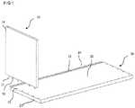
- FIG. 1shows a 3D view from above of a set in an unassembled state of an aspect of the invention.
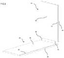
- FIG. 2shows a 3D view from above of a set in an unassembled state of an aspect of the invention.
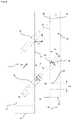
- FIG. 3shows a 3D view from above of a set in an unassembled state of an aspect of the invention.
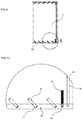
- FIG. 4shows a 3D side view of a set in an assembled state of an aspect of the invention.
- FIG. 5Ashows a side view of a set in an unassembled state of an aspect of the invention.
- FIG. 5Bshows a side view of an embodiment of the rod-shaped element
- FIG. 6shows a side view of a set in an assembled state of an aspect of the invention.
- FIG. 7shows a side view of a set in an unassembled state of an aspect of the invention.
- FIG. 8shows an enlargement of part of the view shown in FIG. 7 .
- FIG. 9shows a side view of a set in an assembled state of an aspect of the invention.
- FIG. 10shows an enlargement of part of the set shown in FIG. 9 .
- FIG. 11shows a view of a set comprising two of the first panel, two of the second panel and one back panel in an unassembled state of an aspect of the invention.
- FIG. 12shows a side view of a set in an assembled state of an aspect of the invention.
- FIG. 13shows an enlargement of part of the set shown in FIG. 12 .
- FIG. 14shows an enlargement of part of the set shown in FIG. 12 .
- FIG. 15shows a side view of an embodiment of first panel.
- FIG. 16shows a view of a set comprising two of the first panel, two of the second in an unassembled state of an aspect of the invention.
- FIGS. 17A-17Dshow enlargements of parts of a set during assembling.
- FIGS. 1-16including a set comprising a first panel 10 , a second panel 20 and a mechanical locking device for locking of the first panel 10 to the second panel 20 .
- the first panel 10comprises a first edge surface 11 and a first panel surface 13 .
- the second panel 20comprises a second panel surface 22 .
- the first edge surface 11is facing or parallel to the second panel surface 22 in a locked position of the first and the second panel 10 , 20 .
- the mechanical locking devicecomprises at least one element 31 at the first edge surface 11 and at least one insertion groove 32 at the second panel surface 22 .
- the element 31may be rod-shaped.
- the rod-shaped element 31is configured to be inserted into the insertion groove 32 .
- the rod-shaped element 31extends at a first angle ⁇ 1 from the first edge surface 11 and the insertion groove 32 extends into the second panel surface 22 at a second angle ⁇ 2 from the second panel surface 22 .
- each element 31may be arranged parallel to each other element 31 .
- each insertion groove 32may be arranged parallel to each other insertion groove 32 .
- the mechanical locking devicefurther comprises at least one locking groove 35 at the first edge surface 11 or at the second panel surface 22 and at least one locking part 34 .
- the locking groove 35comprises at least one locking surface 37 extending at a third angle ⁇ from the first edge surface 11 or from the second panel surface 22 .
- the locking part 34is configured to be inserted into the locking groove 35 and lock against the locking surface 37 , and the third angle ⁇ is different than the first angle ⁇ 1 .
- the first panel 10 and the second panel 20may be panels for a furniture product and may be a part of a frame of a furniture product.
- the setmay be configured for locking the first panel 10 to the second panel 20 with the first panel surface 13 perpendicular or essentially perpendicular to the second panel surface 22 .
- the second panel 20may comprise a fourth edge surface 25 and the insertion groove 32 may be positioned adjacent the fourth edge surface 25 .
- the setmay be configured for locking the first panel 10 to the second panel 20 with the first panel surface 13 parallel or essentially parallel to the fourth edge surface 25 .
- FIGS. 1-3, 5A, 7-8, 11, and 16disclose a set according to an aspect in an unassembled state.
- FIGS. 4, 6, 9-10, and 12-14disclose a set according to an aspect in an assembled state.
- the setmay be assembled by a displacement of the first panel 10 relative the second panel 20 in an assembly direction 111 , 112 , 114 which is essentially parallel with the first panel surface 13 .
- the mechanical locking devicemay be configured to automatically lock the first panel 10 to the second panel 20 when the rod-shaped element 31 is inserted into the insertion groove 32 and the locking part 34 is inserted into the locking groove 35 and locks against the locking surface 37 .
- the setmay be locked when the first edge surface 11 is arranged against the second panel surface 22 .
- the third angle ⁇may be about 45° to about 90° larger than the first angle ⁇ 1 and/or the second angle ⁇ 2 .
- the locking part 34may be positioned at the first edge surface 11 or at the second panel surface 22 and the locking groove 35 may be positioned at the opposite second panel surface 22 or the first edge surface 11 .
- the first angle ⁇ 1 and/or the second angle ⁇ 2may be within the range of about 30° to 60°, or within the range of about 40° to 50°, or about 45°.
- the first angle ⁇ 1 and the second angle ⁇ 2may be parallel or essentially parallel.
- the assembly direction 111 , 112 , 114may be essentially parallel with the first angle ⁇ 1 and/or the second angle ⁇ 2 .
- the third angle ⁇ of the locking surface 37may be within the range of about 70° to 110°, or within the range of about 80° to 100°, or within the range of about 85° to 95°, or about 90°.
- the locking part 34may be flexible.
- the locking part 34in an unflexed/non-compressed state, may be configured to be positioned partly in the locking groove 35 .
- the locking part 34may comprise a spring.
- the locking part 34may be arranged in a locking part groove 38 on the first edge surface 11 or on the second panel surface 22 .
- the locking part 34in a flexed/compressed state, may be configured to be substantially positioned in the locking part groove 38 .
- the locking part 34may be compressed and is substantially positioned in the locking part groove 38 .
- the locking part 34may comprise a spring that facilitates the compression of the locking part 34 .
- the rod-shaped element 31becomes inserted into the insertion groove 32 .
- the locking part 34may expand out from the locking part groove 38 and protrude into the locking groove 35 .
- the first panel 10 and second panel 20will then be locked together, since the positioning of a part of the locking part 34 in the locking groove 35 hinders the first panel 10 from being displaced in relation to the second panel 20 in a direction opposite to the assembly direction.
- the insertion groove 32 and/or the locking groove 35may be a drill hole.
- the drill holemay be a bottom-ended drill hole.
- the insertion groove 32may have a diameter D 2 .
- the insertion groove 32may comprise a chamfer 60 or a rounding, which is configured to guide the rod shaped element during assembling, as shown in FIG. 8 .
- the rod-shaped element 31may be arranged in a rod element groove 36 on the first edge surface 11 on the first panel 10 or on the second panel surface 22 on the second panel 20 .
- the rod-shaped element 31may have a diameter D 1 .
- the diameter D 2 of the insertion groove 32may be larger than the diameter D 1 of the rod-shaped element 31 .
- the diameter D 2 of the insertion groove 32may be about 0.3 to about 0.8 mm larger than the diameter D 1 of the rod-shaped element 31 for optimal assembly.
- the setmay comprise a first panel groove 12 on the first panel surface 13 on the first panel 10 and/or a second panel groove 23 on the second panel surface 22 of the second panel 20 .
- the first panel groove 12 on the first panel surface 13may comprise a width W 1 .
- the second panel groove 23 on the second panel surface 22may comprise a width W 2 .
- the width W 1 of the first panel groove 12may be essentially the same as the width W 2 of the second panel groove 23 .
- the setmay further comprise a back panel 40 .
- the back panel 40may be configured to be inserted in, and optionally cooperate with, the first panel groove 12 and the second panel groove 23 .
- FIG. 6shows that the back panel 40 may be assembled to the first 10 and second 20 panel by displacing the back panel 40 relative the first 10 and second 20 panel in an assembly direction 113 which is essentially perpendicular to the second panel surface 22 of the second panel 20 .
- a thickness T of the back panel 40may be essentially the same as the width W 1 , W 2 of the first 12 and/or second 23 panel groove.
- the playmay be in the range of about 0 mm to about 0.5 mm, or about 0.1 mm to about 0.2 mm.
- the width W 1 , W 2 of the first 12 and/or second 23 panel groove minus a thickness T of the back panel 40i.e., ⁇ W
- ⁇ Wa thickness of the back panel 40
- FIG. 13shows an embodiment comprising a positioning element 50 , for positioning the back panel 40 relative the first 12 and/or second 23 panel groove.
- the positioning element 50may comprise a first wedge element 51 and second wedge element 52 .
- His less than an extension D of the rod shaped element 31 from the first edge surface 11 .
- the rod shaped element 31may have an extension E along the first edge surface 11 .
- At least one panel 10 , 20may have a width W 1 , W 2 of the first 12 and/or second 23 panel groove that allows for a displacement of the extension H of the back panel 40 within the first 12 and/or second 23 panel groove.
- the displacementmay be equal to or larger than ⁇ W.
- all panels 10 , 20have the same width W 1 , W 2 of the first 12 and second 23 panel groove to facilitate the production of the panels.
- a length of the back panel 40may designed to avoid the extension H of the back panel 40 .
- An edge of the back panel 40may be essentially flush with the first edge 11 surface of the first panel 10
- FIG. 15shows a side view of an embodiment of first panel 10 with the first 12 panel groove.
- the first 12 panel groovemay comprise a width W 1 and a height H 1 .
- the first panel 10may comprise a second edge surface 14 and the second panel 20 may comprise a third edge surface 24 .
- the first panel groove 12may be substantially parallel to the second edge surface 14 and the second panel groove 23 may be substantially parallel to the third edge surface 24 .
- the first panel groove 12may extend substantially along the entire second edge surface 14 and the second panel groove 23 may extend essentially along the entire third edge surface 24 .
- the first panel groove 12 and/or the second panel groove 23may be bottom-ended.
- the first 12 and/or second 23 panel groovemay be formed by mechanical cutting, such as milling or sawing.
- the first panel groove 12may be formed in the first panel surface 13 and in a core of the first panel 10 .
- the second panel groove 23may be formed in the second panel surface 22 and in a core of the second panel 20 .
- the first edge surface 11may comprise two or more of said rod-shaped element 31 and the second panel surface 22 may comprise two or more of said insertion groove 32 , and vice versa, which may be arranged linearly, wherein each of the rod-shaped elements 31 is configured to be inserted into one insertion groove 32 .
- a locking of the first panel 10 to the second panel 20 in a direction which is parallel with the second panel surface 22may be obtained by the locking part 34 being inserted into the locking groove 35 and locking against the locking surface 37 .
- the locking surfaceextends at the third angle ⁇ from the first edge surface 11 , where third angle ⁇ is about 45° to about 90° larger than the first angle ⁇ 1 .
- a cross cut of the insertion groove 32 , in a plane parallel to the second panel surface 22may have a shape that matches a cross cut of the rod-shaped element 31 , in a plane parallel to the first edge surface 11 .
- An advantage of thismay be that an improved locking of the first panel 10 to the second panel 20 is obtained and that the assembly of the set of panels is done easily.
- the rod-shaped element 31 and the insertion groove 32are disclosed more in detail in FIGS. 5A-8 and 10 , which show cross cuts along the rod-shaped element 31 and the insertion groove 32 .
- FIG. 5Ashows an embodiment of the locking part 34 comprising a guiding surface 87 at outer edge of the locking part 34 .
- the guiding surfaceis configured to cooperate with an outer edge the locking groove 35 during the insertion of locking part 34 into the locking groove 35 .
- FIG. 5Bshows an embodiment of the rod-shaped element 31 which may be of an elongated shape and comprise a length direction 86 , a width direction 85 and a centre line 81 extending in the length direction.
- the rod-shaped element 31is configured to be inserted in the rod element groove 36 on the first edge surface 11 .
- the rod-shaped element 31is configured to be inserted in the rod element groove 36 on the second panel surface 22 .
- the rod-shaped element 31may be configured to be attached in the rod element groove 36 by friction.
- the rod-shaped element 31may be configured to be glued in the rod element groove 36 .
- the rod-shaped element 31 , the rod element groove 36 and the insertion groove 32may have a substantially circular shape, although other shapes, such as triangular, rectangular, square, etc. are possible.
- the locking groove 35 and the locking part 34may have a substantially circular shape, although other shapes, such as triangular, rectangular, square, etc. are possible.
- a first edge surface 11may have at least one element 31 , while the opposite edge surface may have at least one insertion groove 32 .
- a first edge surface 11may have a combination of at least one element 31 and at least one insertion groove 32 .
- a corresponding second panel surface 22may have a corresponding combination of at least one insertion groove 32 and at least one element 31 .
- the position of at least one rod shaped element 31may be positioned at first distance 83 from the second edge surface 14 .
- the first distancemay be measured from the second edge surface 14 to a centre line 81 of the rod shaped element 31 .
- the corresponding insertion groove 32may be positioned at a second distance 84 from the third edge surface 24 .
- the second distancemay be measured from the third edge surface 24 to a centre line 82 of the insertion groove 32 .
- the first distancemay be different from the second distance which may increase the locking force.
- the difference between the first distance and the second distancemay be in the range of about 0.1 mm to about 0.5 mm.
- the rod-shaped element 31is made from one or more of a wood based material, a polymer material, which may comprise reinforcement, such as glass fibre or a metal.
- the rod shaped element 31may have a waxed surface to facilitate assembly.
- the rod-shaped element 31may be configured to cooperate, in a locked position, with the bottom surface of the insertion groove 32 .
- the sidewalls of the insertion groove 32 and the locking groove 35may comprise material of the core of the first panel 10 or the second panel 20 , dependent on in which panel they are made. According to an aspect they may also be enforced with, e.g., metal or glass fibre.
- the locking groove 35may be impregnated/reinforced with a liquid.
- the first panel 10 and the second panel 20may be assembled by a displacement of the first panel 10 relative the second panel 20 in an assembly direction which is essentially parallel with the first panel surface 13 as shown in FIGS. 5A, 11 and 16 .
- the mechanical locking deviceis according to an aspect configured to automatically lock the first panel 10 to the second panel 20 when the rod-shaped element 31 is inserted into the insertion groove 32 and the locking part 34 is inserted into the locking groove 35 and locks against the locking surface 37 by said displacement of the first panel 10 relative the second panel 20 .
- the setmay be locked when the first edge surface 11 is arranged against the second panel surface 22 .
- the first panel 10may comprise two or more of said first edge surface 11 according to the above.
- one or more of said rod-shaped elements 31may be positioned at two or more of the edges of the first panel 10 , as disclosed in FIGS. 2-4, 9, 11, 12 and 16 .
- the second panel 20may comprise two or more of said fourth edge surface 25 according to the above.
- one or more of said insertion grooves 32may be positioned adjacent two or more of the edges of the second panel 10 , as disclosed in FIGS. 1-4, 9, 11, 12 and 16 .
- two of the first panels 10 , two of the second panels 20 , and one back panel 40may be assembled.
- a left embodiment of the of the first panel 10may be assembled to a bottom embodiment of the second panel 20 by displacing the left embodiment of the first panel 10 relative the bottom embodiment of the second panel 20 in the assembly direction 111 .
- a right embodiment of the of the first panel 10may be assembled to the bottom embodiment of the second panel 20 by displacing the right embodiment of the first panel 10 relative the bottom embodiment of the second panel 20 in the assembly direction 112 .
- An embodiment of the back panel 40may be assembled to the left and right embodiment of the first panel 10 and the bottom embodiment of the second panel 20 by displacing the embodiment of the back panel 40 in an assembly direction 113 which is essentially perpendicular to the second panel surface 22 of the bottom embodiment of the second panel 20 .
- a top embodiment of the second panel 20may be assembled to the left and right embodiment of the first panel 10 and the embodiment of the back panel 40 by displacing the top embodiment of the second panel 20 in the assembly direction 114 .
- two of the first panel 10 , two of the second panel 20may be assembled.
- a left embodiment of the of the first panel 10may be assembled to a bottom embodiment of the second panel 20 by displacing the left embodiment of the first panel 10 relative the bottom embodiment of the second panel 20 in the assembly direction 111 .
- a right embodiment of the of the first panel 10may be assembled to the bottom embodiment of the second panel 20 by displacing the right embodiment of the first panel 10 relative the bottom embodiment of the second panel 20 in the assembly direction 112 .
- a top embodiment of the second panel 20may be assembled to the left and right embodiment of the first panel 10 and the embodiment of the back panel 40 by displacing the top embodiment of the second panel 20 in the assembly direction 114 .
- a length 93 of the back panel 40 which in the locked position may be inserted in the panel groove 12 of the first panel 10may be essentially the same or greater than a length 94 of the first panel 10 at the second edge surface 14 of the first panel.
- the length 93 of the back panel 40may be equal to the length 94 of the first panel 10 plus about half the height H 1 of the panel groove 12 to about two times the height H 1 of the panel groove 12 or equal to the length 94 of the first panel 10 plus the height H 1 of the panel groove 12 .
- FIG. 11shows the length 93 of the back panel 40 which extend between an upper edge 87 of the back panel and a lower edge 88 of the back panel.
- FIGS. 17A-Dshow enlargements of parts of a set during assembling.
- FIG. 17Ashows an embodiment in a first position in which the back panel 40 is inserted in the panel groove 12 of the first panel 10 .
- the upper edge 87 of the back panel 40is below the first edge surface 11 of the first panel.
- FIG. 17Cshows that in this first position the lower edge 88 of the back panel may contact a lower surface 89 of the panel groove 23 of the lower second panel 20 .
- FIG. 17Bshows the embodiment in a second position in which, an upper second panel 20 has been displaced 114 and assembled to the first panel 10 , and the back panel 40 has been displaced to a position in which the upper edge 87 of the back panel 40 is within the panel groove 23 of the upper second panel 20 .
- FIG. 17Dshows that in this second position the lower edge 88 of the back panel may be at a distance 91 from the lower surface 89 of the panel groove 23 of the lower second panel 20 .
- the lower edge 88 of the back panel 40may be positioned at a distance 91 from the second panel surface 22 of the second panel.
- the distancemay be within the range of about 1 ⁇ 3 to about 2 ⁇ 3 a height H 2 of the panel groove 23 of the second panel, or about half the height H 2 of the panel groove 23 of the second panel.
- the height H 2 of the panel groove 23 of the lower second panel groovemay be greater than the height H 2 of the panel groove 23 of the upper second panel groove.
- the setmay be rotated such that the gravity causes the displacement of the back panel to obtain the position in which the upper edge 87 of the back panel 40 is within the panel groove 23 of the upper second panel 20 .
- the back panelmay be displaced by gravity or by hand and the position in which the upper edge 87 of the back panel 40 is within the panel groove 23 of the upper second panel 20 may be maintained by arranging a positioning element 92 between the panel and the panel groove 12 of the first panel and/or between the back panel and the panel groove 23 of the second panel.
- Embodiments of the first panel groove 12may comprise a width W 1 which is essentially the same as a thickness T of the back panel 40 .
- a part of the first panel groove 12may be wider which may allow an embodiment of the positioning element 50 to be positioned between the back panel and the first panel groove 12 to maintain the position in which the upper edge 87 of the back panel 40 is within the panel groove 23 of the upper second panel 20 .
- Embodiments of the second panel groove 24may comprise a width W 2 which is essentially the same as a thickness T of the back panel 40 .
- a part of the second panel groove 23may be wider which may allow an embodiment of the positioning element 50 to be positioned between the back panel 40 and the second panel groove 23 to maintain the position in which the upper edge 87 of the back panel 40 is within the panel groove 23 of the upper second panel 20 .
- the back panelmay be displaceable and the position in which the upper edge 87 of the back panel 40 is within the panel groove 23 of the upper second panel 20 may be maintained by an embodiment of the locking device 4 disclosed in WO2019/125292 or WO2019/125291.
- the entire contents of WO2019/125292 and WO2019/125291are hereby incorporated herein by reference in their entirety.
- the core of the first panel 10 and/or of the second panel 20may be a wood-based core, such as MDF, HDF, OSB, WPC, plywood or particleboard.
- the coremay also be a plastic core comprising thermosetting plastic or thermoplastic, e.g., vinyl, PVC, PU or PET.
- the plastic coremay comprise fillers.
- the first panel 10 and/or the second panel 20may also be of solid wood.
- the first panel 10 and/or the second panel 20may be provided with a decorative layer, such as a foil or a veneer, on one or more surfaces.
- the set of panelsare resilient panels.
- the resilient panelsmay comprise a core comprising thermoplastic material.
- the thermoplastic materialmay be foamed.
- the thermoplastic materialmay comprise polyvinyl chloride (PVC), polyester, polypropylene (PP), polyethylene (PE), polystyrene (PS), polyurethane (PU), polyethylene terephthalate (PET), polyacrylate, methacrylate, polycarbonate, polyvinyl butyral, polybutylene terephthalate, or a combination thereof.
- the coremay be formed of several layers.
- the aspects described abovemay comprise a decorative layer, such as a decorative foil comprising a thermoplastic material.
- the thermoplastic material of the decorative layermay be or comprise polyvinyl chloride (PVC), polyester, polypropylene (PP), polyethylene (PE), polystyrene (PS), polyurethane (PU), polyethylene terephthalate (PET), polyacrylate, methacrylate, polycarbonate, polyvinyl butyral, polybutylene terephthalate, or a combination thereof.
- the decorative foilmay be printed, for example by direct printing, rotogravure, or digital printing.
- the decorative layercomprises melamine, a high pressure laminate (HPL) or a veneer.
- the aspects described abovemay comprise a wear layer such as a film or foil.
- the wear layermay comprise thermoplastic material.
- the thermoplastic materialmay be polyvinyl chloride (PVC), polyester, polypropylene (PP), polyethylene (PE), polystyrene (PS), polyurethane (PU), polyethylene terephthalate (PET), polyacrylate, methacrylate, polycarbonate, polyvinyl butyral, polybutylene terephthalate, or a combination thereof.
- the aspects described abovemay comprise a wood base core, such as HDF, MDF, plywood, particleboard, OSB or Masonite.
- a wood base coresuch as HDF, MDF, plywood, particleboard, OSB or Masonite.
- a setcomprising a first panel ( 10 ), a second panel ( 20 ) and a mechanical locking device for locking the first panel ( 10 ) to the second panel ( 20 ), wherein
- setas in any one of the preceding embodiments, wherein set comprises a first panel groove ( 12 ) on the first panel surface ( 13 ) of the first panel ( 10 ), and a second panel groove ( 23 ) on the second panel surface ( 22 ) of the second panel ( 20 ).
- first panel ( 10 )comprises a second edge surface ( 14 )
- second panel ( 20 )comprises a third edge surface ( 24 )
- first panel groove ( 12 )is substantially parallel to the second edge surface ( 14 )
- second panel groove ( 23 )is substantially parallel to the third edge surface ( 24 ).
- first panel groove ( 12 )extends substantially along the entire second edge surface ( 14 ) and the second panel groove ( 23 ) extends essentially along the entire third edge surface ( 24 ).
Landscapes
- Engineering & Computer Science (AREA)
- General Engineering & Computer Science (AREA)
- Mechanical Engineering (AREA)
- Life Sciences & Earth Sciences (AREA)
- Wood Science & Technology (AREA)
- Connection Of Plates (AREA)
- Furniture Connections (AREA)
- Assembled Shelves (AREA)
Abstract
Description
The present application claims the benefit of Swedish Application No. 1851028-9, filed on Aug. 30, 2018. The entire contents of Swedish Application No. 1851028-9 are hereby incorporated herein by reference in their entirety.
Embodiments of the present invention relate to panels that may be arranged perpendicular to each other and locked together with a mechanical locking device. The panels may be assembled and locked together to obtain a furniture product, such as a bookshelf, a cupboard, a wardrobe, a box, a drawer or a furniture component.
A furniture product provided with a mechanical locking device is known in the art, as evidenced by WO2015/038059. The furniture product comprises a first panel connected perpendicular to a second panel by a mechanical locking device comprising a flexible tongue in an insertion groove.
The above description of various known aspects is the applicant's characterization of such, and is not an admission that any of the above description is considered as prior art.
Embodiments of the present invention address a need to provide panels that may be easily assembled.
It is an object of certain aspects of the present invention to provide an improvement over the above described techniques and known art; particularly to facilitate assembling of panels configured to be assembled without the need of using any tools.
A further object of at least certain aspects of the present invention is to facilitate assembling of panels configured to be assembled with a locking device that is easy to manufacture and to use, which reduces the risk of incorrect installation thereof.
A further object of at least certain aspects of the present invention is to facilitate assembling of panels configured to be assembled in a more stable and aesthetic way.
At least some of these and other objects and advantages that will be apparent from the description have been achieved by a set comprising a first panel, a second panel and a mechanical locking device for locking the first panel to the second panel, wherein the first panel comprises a first edge surface and a first panel surface, the second panel comprises a second panel surface, the first edge surface is facing and/or is parallel with the second panel surface in a locked position of the first and the second panel, the mechanical locking device comprises at least one rod-shaped element at the first edge surface and at least one insertion groove at the second panel surface, the rod-shaped element is configured to be inserted into the insertion groove, the rod-shaped element extends at a first angle from the first edge surface, the insertion groove extends into the second panel surface at an angle from the second panel surface, the mechanical locking device further comprises at least one locking groove at the first edge surface or at the second panel surface and at least one locking part, wherein the locking groove comprises at least one locking surface extending at a third angle from the first edge surface or from the second panel surface, the locking part is configured to be inserted into the locking groove and lock against the locking surface, and the third angle is different than the first angle.
According to an aspect the mechanical locking device is configured to obtain the locked position by displacing first panel relative the second panel in an assembly direction which is essentially parallel with the first panel surface.
According to an aspect the third angle is about 45° to about 90° larger than the first angle.
According to an aspect the locking part is positioned at the first edge surface or at the second panel surface and the locking groove is positioned at the opposite second panel surface or first edge surface.
According to an aspect the first angle is within the range of about 30° to about 60°, or within the range of about 40° to about 50°, or about 45°.
According to an aspect the assembly direction is essentially parallel with at least one of the first angle and the second angle.
According to an aspect the locking part is flexible.
According to an aspect the locking part, in an unflexed/non-compressed state, is configured to be positioned partly in the locking groove.
According to an aspect the locking part comprises a spring.
According to an aspect the locking part is arranged in a locking part groove on the first edge surface or on the second panel surface.
According to an aspect the locking part, in a flexed/compressed state, is configured to be substantially positioned in the locking part groove.
According to an aspect the insertion groove and/or the locking groove is a drill hole.
According to an aspect the drill hole is a bottom-ended drill hole.
According to an aspect the rod-shaped element is arranged in a rod element groove in the first edge surface.
According to an aspect the set comprises a first panel groove on the first panel surface on the first panel and a second panel groove on the second panel surface of the second panel.
According to an aspect a width of the first panel groove is essentially the same as a width of the second panel groove.
According to an aspect the set further comprises a back panel configured to be inserted in, and optionally to cooperate with, the first and second panel groove.
According to an aspect the first panel comprises a second edge surface, the second panel comprises a third edge surface, the first panel groove is substantially parallel to the second edge surface and the second panel groove is substantially parallel to the third edge surface.
According to an aspect the first panel groove extends substantially along the entire second edge surface and the second panel groove extends essentially along the entire third edge surface.
According to an aspect the first panel groove and/or the second panel groove is bottom-ended.
According to an aspect an extension of the back panel from the first edge of the first panel, when one first panel, one second panel, and one back panel have been assembled, is less than an extension of the rod shaped element from the first edge surface.
According to an aspect the core of the first panel and/or of the second panel may be a wood-based core, such as MDF, HDF, OSB, WPC, plywood or particleboard. The core may also be a plastic core comprising thermosetting plastic or thermoplastic, e.g., vinyl, PVC, PU or PET. The plastic core may comprise fillers.
The first panel and/or the second panel may also be of solid wood.
The first panel and/or the second panel may be provided with a decorative layer, such as a foil or a veneer, on one or more surfaces.
At least some of the above identified and other objects and advantages that may be apparent from the description have been achieved by a locking device for a furniture product in accordance with the above.
These and other aspects, features and advantages of which embodiments of the invention are capable of, will be apparent and elucidated from the following description of embodiments and aspects of the present invention, reference being made to the accompanying drawings, in which
Specific embodiments of the invention will now be described with reference to the accompanying drawings. This invention may, however, be embodied in many different forms and should not be construed as limited to the embodiments set forth herein; rather, these embodiments are provided so that this disclosure will be thorough and complete, and will fully convey the scope of the invention to those skilled in the art. The terminology used in the detailed description of the embodiments illustrated in the accompanying drawings is not intended to be limiting of the invention. In the drawings, like numbers refer to like elements.
The terminology used herein is for the purpose of describing particular aspects of the disclosure only, and is not intended to limit the disclosure. As used herein, the singular forms “a”, “an” and “the” are intended to include the plural forms as well, unless the context clearly indicates otherwise.
In the drawings and specification, there have been disclosed exemplary aspects of the disclosure. However, many variations and modifications may be made to these aspects without substantially departing from the principles of the present disclosure. Thus, the disclosure should be regarded as illustrative rather than restrictive, and not as being limited to the particular aspects discussed above. Accordingly, although specific terms are employed, they are used in a generic and descriptive sense only and not for purposes of limitation, for example, definition of dimensions such as width or breadth or height or length or diameter depends on how exemplary aspects are depicted, hence, if depicted differently, a shown width or diameter in one depiction is a length or thickness in another depiction.
It should be noted that the word “comprising” does not necessarily exclude the presence of other elements or steps than those listed and the words “a” or “an” preceding an element do not exclude the presence of a plurality of such elements. It should further be noted that any reference signs do not limit the scope of the claims, that the example aspects may be implemented at least in part by means of both hardware and software, and that several “means”, “units” or “devices” may be represented by the same item of hardware.
The different aspects, alternatives and embodiments of the invention disclosed herein may be combined with one or more of the other aspects, alternatives and embodiments described herein. Two or more aspects may be combined.
Embodiments of the invention are shown inFIGS. 1-16 including a set comprising afirst panel 10, asecond panel 20 and a mechanical locking device for locking of thefirst panel 10 to thesecond panel 20. Thefirst panel 10 comprises afirst edge surface 11 and afirst panel surface 13. Thesecond panel 20 comprises asecond panel surface 22. Thefirst edge surface 11 is facing or parallel to thesecond panel surface 22 in a locked position of the first and thesecond panel element 31 at thefirst edge surface 11 and at least oneinsertion groove 32 at thesecond panel surface 22. Theelement 31 may be rod-shaped. The rod-shapedelement 31 is configured to be inserted into theinsertion groove 32. The rod-shapedelement 31 extends at a first angle α1 from thefirst edge surface 11 and theinsertion groove 32 extends into thesecond panel surface 22 at a second angle α2 from thesecond panel surface 22. When there are more than oneelement 31, eachelement 31 may be arranged parallel to eachother element 31. When there are more than oneinsertion grooves 32, eachinsertion groove 32 may be arranged parallel to eachother insertion groove 32. The mechanical locking device further comprises at least one lockinggroove 35 at thefirst edge surface 11 or at thesecond panel surface 22 and at least one lockingpart 34. The lockinggroove 35 comprises at least one lockingsurface 37 extending at a third angle β from thefirst edge surface 11 or from thesecond panel surface 22. The lockingpart 34 is configured to be inserted into the lockinggroove 35 and lock against the lockingsurface 37, and the third angle β is different than the first angle α1.
Thefirst panel 10 and thesecond panel 20 may be panels for a furniture product and may be a part of a frame of a furniture product.
The set may be configured for locking thefirst panel 10 to thesecond panel 20 with thefirst panel surface 13 perpendicular or essentially perpendicular to thesecond panel surface 22.
Thesecond panel 20 may comprise afourth edge surface 25 and theinsertion groove 32 may be positioned adjacent thefourth edge surface 25. The set may be configured for locking thefirst panel 10 to thesecond panel 20 with thefirst panel surface 13 parallel or essentially parallel to thefourth edge surface 25.
The third angle β may be about 45° to about 90° larger than the first angle α1 and/or the second angle α2.
The lockingpart 34 may be positioned at thefirst edge surface 11 or at thesecond panel surface 22 and the lockinggroove 35 may be positioned at the oppositesecond panel surface 22 or thefirst edge surface 11.
The first angle α1 and/or the second angle α2 may be within the range of about 30° to 60°, or within the range of about 40° to 50°, or about 45°. The first angle α1 and the second angle α2 may be parallel or essentially parallel.
Theassembly direction
The third angle β of the lockingsurface 37 may be within the range of about 70° to 110°, or within the range of about 80° to 100°, or within the range of about 85° to 95°, or about 90°.
The lockingpart 34 may be flexible.
The lockingpart 34, in an unflexed/non-compressed state, may be configured to be positioned partly in the lockinggroove 35.
The lockingpart 34 may comprise a spring.
The lockingpart 34 may be arranged in a lockingpart groove 38 on thefirst edge surface 11 or on thesecond panel surface 22.
The lockingpart 34, in a flexed/compressed state, may be configured to be substantially positioned in the lockingpart groove 38.
When the first10 and second20 panels are assembled together the lockingpart 34 may be compressed and is substantially positioned in the lockingpart groove 38. The lockingpart 34 may comprise a spring that facilitates the compression of the lockingpart 34. When thefirst panel 10 is displaced in relation to thesecond panel 20 in the assembly direction, the rod-shapedelement 31 becomes inserted into theinsertion groove 32. When the lockingpart 34 meets the lockinggroove 35 the lockingpart 34 may expand out from the lockingpart groove 38 and protrude into the lockinggroove 35. Thefirst panel 10 andsecond panel 20 will then be locked together, since the positioning of a part of the lockingpart 34 in the lockinggroove 35 hinders thefirst panel 10 from being displaced in relation to thesecond panel 20 in a direction opposite to the assembly direction.
Theinsertion groove 32 and/or the lockinggroove 35 may be a drill hole. The drill hole may be a bottom-ended drill hole.
Theinsertion groove 32 may have a diameter D2.
Theinsertion groove 32 may comprise achamfer 60 or a rounding, which is configured to guide the rod shaped element during assembling, as shown inFIG. 8 .
The rod-shapedelement 31 may be arranged in arod element groove 36 on thefirst edge surface 11 on thefirst panel 10 or on thesecond panel surface 22 on thesecond panel 20.
The rod-shapedelement 31 may have a diameter D1. The diameter D2 of theinsertion groove 32 may be larger than the diameter D1 of the rod-shapedelement 31. The diameter D2 of theinsertion groove 32 may be about 0.3 to about 0.8 mm larger than the diameter D1 of the rod-shapedelement 31 for optimal assembly.
According to an aspect the set may comprise afirst panel groove 12 on thefirst panel surface 13 on thefirst panel 10 and/or asecond panel groove 23 on thesecond panel surface 22 of thesecond panel 20.
Thefirst panel groove 12 on thefirst panel surface 13 may comprise a width W1.
Thesecond panel groove 23 on thesecond panel surface 22 may comprise a width W2.
The width W1 of thefirst panel groove 12 may be essentially the same as the width W2 of thesecond panel groove 23.
The set may further comprise aback panel 40. Theback panel 40 may be configured to be inserted in, and optionally cooperate with, thefirst panel groove 12 and thesecond panel groove 23.
There may be a play between theback panel 40 and the first12 and/or second23 panel groove which may facilitate a displacement of an edge of theback panel 40 in the first12 and/or second23 panel grooves. The play may be in the range of about 0 mm to about 0.5 mm, or about 0.1 mm to about 0.2 mm.
In one aspect the width W1, W2 of the first12 and/or second23 panel groove minus a thickness T of theback panel 40, i.e., ΔW, is equal to or larger than an extension H of theback panel 40 in relation to thefirst panel 10 orsecond panel 20 after afirst panel 10, asecond panel 20 and aback panel 40 have been assembled, i.e., ΔW≥H, seeFIGS. 12-15 .
In one aspect H is less than an extension D of the rod shapedelement 31 from thefirst edge surface 11.
The rod shapedelement 31 may have an extension E along thefirst edge surface 11.
In one aspect, if a set comprising two of thefirst panel 10 and two of thesecond panel 20 are to be assembled, at least onepanel back panel 40 within the first12 and/or second23 panel groove. The displacement may be equal to or larger than ΔW. In one aspect, allpanels
A length of theback panel 40 may designed to avoid the extension H of theback panel 40. An edge of theback panel 40 may be essentially flush with thefirst edge 11 surface of thefirst panel 10
Thefirst panel groove 12 may extend substantially along the entiresecond edge surface 14 and thesecond panel groove 23 may extend essentially along the entirethird edge surface 24.
Thefirst panel groove 12 and/or thesecond panel groove 23 may be bottom-ended.
The first12 and/or second23 panel groove may be formed by mechanical cutting, such as milling or sawing.
Thefirst panel groove 12 may be formed in thefirst panel surface 13 and in a core of thefirst panel 10. Thesecond panel groove 23 may be formed in thesecond panel surface 22 and in a core of thesecond panel 20.
Thefirst edge surface 11 may comprise two or more of said rod-shapedelement 31 and thesecond panel surface 22 may comprise two or more of saidinsertion groove 32, and vice versa, which may be arranged linearly, wherein each of the rod-shapedelements 31 is configured to be inserted into oneinsertion groove 32.
A locking of thefirst panel 10 to thesecond panel 20 in a direction which is parallel with thesecond panel surface 22 may be obtained by the lockingpart 34 being inserted into the lockinggroove 35 and locking against the lockingsurface 37. The locking surface extends at the third angle β from thefirst edge surface 11, where third angle β is about 45° to about 90° larger than the first angle α1.
A cross cut of theinsertion groove 32, in a plane parallel to thesecond panel surface 22, may have a shape that matches a cross cut of the rod-shapedelement 31, in a plane parallel to thefirst edge surface 11. An advantage of this may be that an improved locking of thefirst panel 10 to thesecond panel 20 is obtained and that the assembly of the set of panels is done easily.
The rod-shapedelement 31 and theinsertion groove 32 are disclosed more in detail inFIGS. 5A-8 and 10 , which show cross cuts along the rod-shapedelement 31 and theinsertion groove 32.
According to an aspect the rod-shapedelement 31 is configured to be inserted in therod element groove 36 on thesecond panel surface 22.
According to an aspect the rod-shapedelement 31 may be configured to be attached in therod element groove 36 by friction.
According to an aspect the rod-shapedelement 31 may be configured to be glued in therod element groove 36.
According to an aspect the rod-shapedelement 31, therod element groove 36 and theinsertion groove 32 may have a substantially circular shape, although other shapes, such as triangular, rectangular, square, etc. are possible.
According to one aspect the lockinggroove 35 and the lockingpart 34 may have a substantially circular shape, although other shapes, such as triangular, rectangular, square, etc. are possible.
According to an aspect, which is shown inFIG. 7 , afirst edge surface 11 may have at least oneelement 31, while the opposite edge surface may have at least oneinsertion groove 32.
According to a further aspect, afirst edge surface 11 may have a combination of at least oneelement 31 and at least oneinsertion groove 32. A correspondingsecond panel surface 22 may have a corresponding combination of at least oneinsertion groove 32 and at least oneelement 31.
According to an aspect, which is shown inFIG. 8 , the position of at least one rod shapedelement 31 may be positioned atfirst distance 83 from thesecond edge surface 14. The first distance may be measured from thesecond edge surface 14 to acentre line 81 of the rod shapedelement 31. Thecorresponding insertion groove 32 may be positioned at asecond distance 84 from thethird edge surface 24. The second distance may be measured from thethird edge surface 24 to acentre line 82 of theinsertion groove 32. The first distance may be different from the second distance which may increase the locking force.
The difference between the first distance and the second distance may be in the range of about 0.1 mm to about 0.5 mm.
According to an aspect the rod-shapedelement 31 is made from one or more of a wood based material, a polymer material, which may comprise reinforcement, such as glass fibre or a metal.
According to an aspect the rod shapedelement 31 may have a waxed surface to facilitate assembly.
According to an aspect the rod-shapedelement 31 may be configured to cooperate, in a locked position, with the bottom surface of theinsertion groove 32.
The sidewalls of theinsertion groove 32 and the lockinggroove 35 may comprise material of the core of thefirst panel 10 or thesecond panel 20, dependent on in which panel they are made. According to an aspect they may also be enforced with, e.g., metal or glass fibre.
According to an aspect the lockinggroove 35 may be impregnated/reinforced with a liquid.
According to an aspect thefirst panel 10 and thesecond panel 20 may be assembled by a displacement of thefirst panel 10 relative thesecond panel 20 in an assembly direction which is essentially parallel with thefirst panel surface 13 as shown inFIGS. 5A, 11 and 16 . The mechanical locking device is according to an aspect configured to automatically lock thefirst panel 10 to thesecond panel 20 when the rod-shapedelement 31 is inserted into theinsertion groove 32 and the lockingpart 34 is inserted into the lockinggroove 35 and locks against the lockingsurface 37 by said displacement of thefirst panel 10 relative thesecond panel 20. The set may be locked when thefirst edge surface 11 is arranged against thesecond panel surface 22.
According to an aspect thefirst panel 10 may comprise two or more of saidfirst edge surface 11 according to the above. Put in another way, one or more of said rod-shapedelements 31 may be positioned at two or more of the edges of thefirst panel 10, as disclosed inFIGS. 2-4, 9, 11, 12 and 16 .
According to an aspect thesecond panel 20 may comprise two or more of saidfourth edge surface 25 according to the above. Put in another way, one or more of saidinsertion grooves 32 may be positioned adjacent two or more of the edges of thesecond panel 10, as disclosed inFIGS. 1-4, 9, 11, 12 and 16 .
According to an aspect, as shown inFIG. 11 , two of thefirst panels 10, two of thesecond panels 20, and oneback panel 40 may be assembled.
A left embodiment of the of thefirst panel 10 may be assembled to a bottom embodiment of thesecond panel 20 by displacing the left embodiment of thefirst panel 10 relative the bottom embodiment of thesecond panel 20 in theassembly direction 111. A right embodiment of the of thefirst panel 10 may be assembled to the bottom embodiment of thesecond panel 20 by displacing the right embodiment of thefirst panel 10 relative the bottom embodiment of thesecond panel 20 in theassembly direction 112. An embodiment of theback panel 40 may be assembled to the left and right embodiment of thefirst panel 10 and the bottom embodiment of thesecond panel 20 by displacing the embodiment of theback panel 40 in anassembly direction 113 which is essentially perpendicular to thesecond panel surface 22 of the bottom embodiment of thesecond panel 20. A top embodiment of thesecond panel 20 may be assembled to the left and right embodiment of thefirst panel 10 and the embodiment of theback panel 40 by displacing the top embodiment of thesecond panel 20 in theassembly direction 114.
According to an aspect, as shown inFIG. 16 , two of thefirst panel 10, two of thesecond panel 20, may be assembled.
A left embodiment of the of thefirst panel 10 may be assembled to a bottom embodiment of thesecond panel 20 by displacing the left embodiment of thefirst panel 10 relative the bottom embodiment of thesecond panel 20 in theassembly direction 111. A right embodiment of the of thefirst panel 10 may be assembled to the bottom embodiment of thesecond panel 20 by displacing the right embodiment of thefirst panel 10 relative the bottom embodiment of thesecond panel 20 in theassembly direction 112. A top embodiment of thesecond panel 20 may be assembled to the left and right embodiment of thefirst panel 10 and the embodiment of theback panel 40 by displacing the top embodiment of thesecond panel 20 in theassembly direction 114.
Alength 93 of theback panel 40 which in the locked position may be inserted in thepanel groove 12 of thefirst panel 10 may be essentially the same or greater than alength 94 of thefirst panel 10 at thesecond edge surface 14 of the first panel. Thelength 93 of theback panel 40 may be equal to thelength 94 of thefirst panel 10 plus about half the height H1 of thepanel groove 12 to about two times the height H1 of thepanel groove 12 or equal to thelength 94 of thefirst panel 10 plus the height H1 of thepanel groove 12.FIG. 11 shows thelength 93 of theback panel 40 which extend between anupper edge 87 of the back panel and alower edge 88 of the back panel.
The height H2 of thepanel groove 23 of the lower second panel groove may be greater than the height H2 of thepanel groove 23 of the upper second panel groove. The set may be rotated such that the gravity causes the displacement of the back panel to obtain the position in which theupper edge 87 of theback panel 40 is within thepanel groove 23 of the uppersecond panel 20.
The back panel may be displaced by gravity or by hand and the position in which theupper edge 87 of theback panel 40 is within thepanel groove 23 of the uppersecond panel 20 may be maintained by arranging apositioning element 92 between the panel and thepanel groove 12 of the first panel and/or between the back panel and thepanel groove 23 of the second panel.
Embodiments of thefirst panel groove 12 may comprise a width W1 which is essentially the same as a thickness T of theback panel 40. A part of thefirst panel groove 12 may be wider which may allow an embodiment of thepositioning element 50 to be positioned between the back panel and thefirst panel groove 12 to maintain the position in which theupper edge 87 of theback panel 40 is within thepanel groove 23 of the uppersecond panel 20.
Embodiments of thesecond panel groove 24 may comprise a width W2 which is essentially the same as a thickness T of theback panel 40. A part of thesecond panel groove 23 may be wider which may allow an embodiment of thepositioning element 50 to be positioned between theback panel 40 and thesecond panel groove 23 to maintain the position in which theupper edge 87 of theback panel 40 is within thepanel groove 23 of the uppersecond panel 20.
The back panel may be displaceable and the position in which theupper edge 87 of theback panel 40 is within thepanel groove 23 of the uppersecond panel 20 may be maintained by an embodiment of the locking device4 disclosed in WO2019/125292 or WO2019/125291. The entire contents of WO2019/125292 and WO2019/125291 are hereby incorporated herein by reference in their entirety.
The core of thefirst panel 10 and/or of thesecond panel 20 may be a wood-based core, such as MDF, HDF, OSB, WPC, plywood or particleboard. The core may also be a plastic core comprising thermosetting plastic or thermoplastic, e.g., vinyl, PVC, PU or PET. The plastic core may comprise fillers.
Thefirst panel 10 and/or thesecond panel 20 may also be of solid wood.
Thefirst panel 10 and/or thesecond panel 20 may be provided with a decorative layer, such as a foil or a veneer, on one or more surfaces.
According to an aspect the set of panels are resilient panels. The resilient panels may comprise a core comprising thermoplastic material. The thermoplastic material may be foamed.
The thermoplastic material may comprise polyvinyl chloride (PVC), polyester, polypropylene (PP), polyethylene (PE), polystyrene (PS), polyurethane (PU), polyethylene terephthalate (PET), polyacrylate, methacrylate, polycarbonate, polyvinyl butyral, polybutylene terephthalate, or a combination thereof. The core may be formed of several layers.
The aspects described above may comprise a decorative layer, such as a decorative foil comprising a thermoplastic material. The thermoplastic material of the decorative layer may be or comprise polyvinyl chloride (PVC), polyester, polypropylene (PP), polyethylene (PE), polystyrene (PS), polyurethane (PU), polyethylene terephthalate (PET), polyacrylate, methacrylate, polycarbonate, polyvinyl butyral, polybutylene terephthalate, or a combination thereof. The decorative foil may be printed, for example by direct printing, rotogravure, or digital printing. According to an aspect the decorative layer comprises melamine, a high pressure laminate (HPL) or a veneer.
The aspects described above may comprise a wear layer such as a film or foil. The wear layer may comprise thermoplastic material. The thermoplastic material may be polyvinyl chloride (PVC), polyester, polypropylene (PP), polyethylene (PE), polystyrene (PS), polyurethane (PU), polyethylene terephthalate (PET), polyacrylate, methacrylate, polycarbonate, polyvinyl butyral, polybutylene terephthalate, or a combination thereof.
The aspects described above may comprise a wood base core, such as HDF, MDF, plywood, particleboard, OSB or Masonite.
The different aspects, embodiments and alternatives described above may be combined with one or more of the other described aspects, embodiments and alternatives.
1. A set comprising a first panel (10), a second panel (20) and a mechanical locking device for locking the first panel (10) to the second panel (20), wherein
- the first panel (10) comprises a first edge surface (11) and a first panel surface (13),
- the second panel (20) comprises a second panel surface (22),
- the first edge surface (11) is facing or parallel to the second panel surface (22) in a locked position of the first and the second panel (10,20),
- the mechanical locking device comprises at least one rod-shaped element (31) at the first edge surface (11) and at least one insertion groove (32) at the second panel surface (22),
- the rod-shaped element (31) is configured to cooperate with the insertion groove (32) in the locked position,
- the rod-shaped element (31) extends at a first angle (α1) from the first edge surface (11),
- the insertion groove (32) extends into the second panel surface (22) at a second angle (α2) from the second panel surface (22),
- the mechanical locking device further comprises a locking groove (35) at the second panel surface (22) and a locking part (34) at the first edge surface (11) or a locking groove (35) at the first edge surface (11) and a locking part (34) at the second panel surface (22),
- the locking groove (35) comprises at least one locking surface (37) extending at a third angle (β) from the first edge surface (11) or from the second panel surface (22),
- the locking part (34) is configured to cooperate with the locking groove (35) and lock against the locking surface (37) in the locked position,
- the third angle (β) is different than the first angle (α1),
- the first angle (α1) is within the range of about 30° to 60°, or within the range of about 40° to about 50°, or about 45°, and
- the mechanical locking device is configured to obtain the locked position by displacing first panel (10) relative the second panel (20) in an assembly direction which is essentially parallel with the first panel surface (13).
2. The set as inembodiment 1, wherein the assembly direction (111,112,114) is essentially parallel with at least one of the first angle (α1) and the second angle (α2).
3. The set as claimed inembodiment 1 or 2, wherein the third angle (β) is about 45° to about 90° larger than the first angle (α1).
4. The set as in any one of the preceding embodiments, wherein the third angle (β) of the locking surface (37) is in the range of about 70° to 110°, or within the range of about 80° to 100°, or within the range of about 85° to 95°, or about 90°.
5. The set as in any one of the preceding embodiments, wherein the locking part (34) is flexible.
6. The set as in any one of the preceding embodiments, wherein the locking part (34), in an unflexed/non-compressed state, is configured to be positioned partly in the locking groove (35).
7. The set as in any one of the preceding embodiments, wherein the locking part (34) comprises a spring.
8. The set as in any one of the preceding embodiments, wherein the locking part (34) is arranged in a locking part groove (38) on the first edge surface (11) or at the second panel surface (22).
9. The set as in claim8, wherein the locking part (34), in a flexed/compressed state, is configured to be substantially positioned in the locking part groove (38).
10. The set as in any one of the preceding embodiments, wherein at least one of the insertion groove (32) and the locking groove (35) is a drill hole.
11. The set as inclaim 10, wherein the drill hole is a bottom-ended drill hole.
12. The set as in any one of the preceding embodiments, wherein the rod-shaped element (31) is arranged in a rod element groove (36) in the first edge surface (11).
13. The set as in any one of the preceding embodiments, wherein set comprises a first panel groove (12) on the first panel surface (13) of the first panel (10), and a second panel groove (23) on the second panel surface (22) of the second panel (20).
14. The set as inclaim 13, wherein a width (W1) of the first panel groove (12) is essentially the same as the width (W2) of the second panel groove (23).
15. The set as in any ofembodiments 13 to 14, wherein the set further comprises a back panel (40) configured to be inserted in, and optionally to cooperate with, the first and second panel groove (12,23).
16. The set as in any ofembodiments 13 to 15, wherein the first panel (10) comprises a second edge surface (14), the second panel (20) comprises a third edge surface (24), the first panel groove (12) is substantially parallel to the second edge surface (14) and the second panel groove (23) is substantially parallel to the third edge surface (24).
17. The set as in any ofembodiments 13 to 16, wherein the first panel groove (12) extends substantially along the entire second edge surface (14) and the second panel groove (23) extends essentially along the entire third edge surface (24).
18. The set as in any ofembodiments 13 to 17, wherein at least one of the first panel groove (12) and the second panel groove (23) is bottom-ended.
19. The set as in any of embodiments 16 to 18, wherein an extension (H) of the back panel (40) from the first edge (11) of the first panel (10), when one first panel, one second panel and one back panel have been assembled, is less than an extension of the rod shaped element (31) from the first edge surface (11) of the first panel (10).
Claims (17)
1. A set comprising a first panel, a second panel and a mechanical locking device for locking the first panel to the second panel, wherein:
the first panel comprises a first edge surface and a first panel surface,
the second panel comprises a second panel surface,
the first edge surface is facing or parallel to the second panel surface in a locked position of the first and the second panel,
the mechanical locking device comprises at least one rod-shaped element at the first edge surface and at least one insertion groove at the second panel surface,
the rod-shaped element is configured to cooperate with the insertion groove in the locked position,
the rod-shaped element extends at a first angle from the first edge surface,
the insertion groove extends into the second panel surface at a second angle from the second panel surface,
the mechanical locking device further comprises a locking groove at the second panel surface and a locking part at the first edge surface or a locking groove at the first edge surface and a locking part at the second panel surface,
the locking groove comprises at least one locking surface extending at a third angle from the first edge surface or from the second panel surface,
the locking part is configured to cooperate with the locking groove and lock against the locking surface in the locked position,
the third angle is different than the first angle, the first angle is within the range of about 30° to 60°,
the mechanical locking device is configured to obtain the locked position by displacing the first panel relative the second panel in an assembly, direction which is essentially parallel with the first panel surface, the assembly direction being essentially parallel with at least one of the first angle and the second angle,
the locking part is arranged in a locking part groove on the first edge surface or at the second panel surface, wherein when the locking part is configured to resiliently retract into the locking part groove and is biased to extend in a direction away from the locking part groove, and
the first and second panels are configured to become locked by sliding an end surface of the locking part along the first or second panel surface, during which time the rod-shaped element slides into the insertion groove and the locking part resiliently retracts into the locking part groove, at least until the locking part springs into the locking groove in the direction away from the locking part groove such that, in the looked position of the first and second panels; the locking part extends into the locking groove.
2. The set as claimed inclaim 1 , wherein the third angle is about 45° to about 90° larger than the first angle.
3. The set as claimed inclaim 1 , wherein the third angle of the locking surface is in the range of about 70° to 110°.
4. The set as claimed inclaim 1 , wherein the locking part is flexible.
5. The set as claimed inclaim 1 , wherein the locking part, in an unflexed/non-compressed state, is configured to be positioned partly in the locking groove.
6. The set as claimed inclaim 1 , wherein the locking part comprises a spring.
7. The set as claimed inclaim 1 , wherein the locking part, in a flexed/compressed state, is configured to be substantially positioned in the locking part groove.
8. The set as claimed inclaim 1 , wherein at least one of the insertion groove and the locking groove is a drill hole.
9. The set as claimed inclaim 8 , wherein the drill hole is a bottom-ended drill hole.
10. The set as claimed inclaim 1 , wherein the rod-shaped element is arranged in a rod element groove in the first edge surface.
11. The set as claimed inclaim 1 , wherein set comprises a first panel groove on the first panel surface of the first panel, and a second panel groove on the second panel surface of the second panel.
12. The set as claimed inclaim 11 , wherein a width of the first panel groove is essentially the same as the width of the second panel groove.
13. The set as claimed inclaim 11 , wherein the set further comprises a back panel configured to be inserted in, and optionally to cooperate with, the first and second panel grooves.
14. The set as claimed inclaim 13 , wherein an extension of the back panel from the first edge of the first panel, when the first panel, the second panel and the back panel have been assembled, is less than an extension of the rod shaped element from the first edge surface of the first panel.
15. The set as claimed inclaim 11 , wherein the first panel comprises a second edge surface, the second panel comprises a third edge surface, the first panel groove is substantially parallel to the second edge surface and the second panel groove is substantially parallel to the third edge surface.
16. The set as claimed inclaim 15 , wherein the first panel groove extends substantially along the entire second edge surface and the second panel groove extends essentially along the entire third edge surface.
17. The set as claimed inclaim 11 , wherein at least one of the first panel groove and the second panel groove is bottom-ended.
Priority Applications (1)
| Application Number | Priority Date | Filing Date | Title |
|---|---|---|---|
| US17/886,517US12408748B2 (en) | 2018-08-30 | 2022-08-12 | Set of panels with a mechanical locking device |
Applications Claiming Priority (3)
| Application Number | Priority Date | Filing Date | Title |
|---|---|---|---|
| SE18510289 | 2018-08-30 | ||
| SE1851028-9 | 2018-08-30 | ||
| SE1851028 | 2018-08-30 |
Related Child Applications (1)
| Application Number | Title | Priority Date | Filing Date |
|---|---|---|---|
| US17/886,517ContinuationUS12408748B2 (en) | 2018-08-30 | 2022-08-12 | Set of panels with a mechanical locking device |
Publications (2)
| Publication Number | Publication Date |
|---|---|
| US20200069048A1 US20200069048A1 (en) | 2020-03-05 |
| US11445819B2true US11445819B2 (en) | 2022-09-20 |
Family
ID=69641807
Family Applications (2)
| Application Number | Title | Priority Date | Filing Date |
|---|---|---|---|
| US16/553,325Active2040-08-12US11445819B2 (en) | 2018-08-30 | 2019-08-28 | Set of panels with a mechanical locking device |
| US17/886,517Active2040-09-24US12408748B2 (en) | 2018-08-30 | 2022-08-12 | Set of panels with a mechanical locking device |
Family Applications After (1)
| Application Number | Title | Priority Date | Filing Date |
|---|---|---|---|
| US17/886,517Active2040-09-24US12408748B2 (en) | 2018-08-30 | 2022-08-12 | Set of panels with a mechanical locking device |
Country Status (25)
| Country | Link |
|---|---|
| US (2) | US11445819B2 (en) |
| EP (2) | EP4410151A3 (en) |
| JP (2) | JP7479350B2 (en) |
| KR (1) | KR102763186B1 (en) |
| CN (1) | CN112639303A (en) |
| AU (1) | AU2019333191B2 (en) |
| CA (1) | CA3109437A1 (en) |
| CL (1) | CL2021000441A1 (en) |
| CO (1) | CO2021003067A2 (en) |
| DK (1) | DK3844407T3 (en) |
| EA (1) | EA202190506A1 (en) |
| ES (1) | ES2980808T3 (en) |
| FI (1) | FI3844407T3 (en) |
| HR (1) | HRP20240594T1 (en) |
| HU (1) | HUE066232T2 (en) |
| LT (1) | LT3844407T (en) |
| MX (1) | MX2021002167A (en) |
| MY (1) | MY205303A (en) |
| PE (1) | PE20210492A1 (en) |
| PL (1) | PL3844407T3 (en) |
| PT (1) | PT3844407T (en) |
| RS (1) | RS65510B1 (en) |
| SI (1) | SI3844407T1 (en) |
| WO (1) | WO2020046193A1 (en) |
| ZA (1) | ZA202101099B (en) |
Cited By (5)
| Publication number | Priority date | Publication date | Assignee | Title |
|---|---|---|---|---|
| US20210262507A1 (en)* | 2020-02-26 | 2021-08-26 | Välinge Innovation AB | Set of panels with a mechanical locking device |
| US20220397144A1 (en)* | 2021-06-11 | 2022-12-15 | Välinge Innovation AB | Static load compression spring |
| US20220397140A1 (en)* | 2021-06-11 | 2022-12-15 | Välinge Innovation AB | Mechanical connection arrangement for panels |
| US20240018986A1 (en)* | 2022-07-18 | 2024-01-18 | Välinge Innovation AB | Joinery product with a mechanical locking device |
| US12408748B2 (en) | 2018-08-30 | 2025-09-09 | Välinge Innovation AB | Set of panels with a mechanical locking device |
Families Citing this family (48)
| Publication number | Priority date | Publication date | Assignee | Title |
|---|---|---|---|---|
| UA109938C2 (en) | 2011-05-06 | 2015-10-26 | MECHANICAL LOCKING SYSTEM FOR CONSTRUCTION PANELS | |
| CN109854597B (en) | 2013-09-16 | 2021-03-19 | 瓦林格创新股份有限公司 | Combination product and method for assembling the same |
| US9726210B2 (en) | 2013-09-16 | 2017-08-08 | Valinge Innovation Ab | Assembled product and a method of assembling the product |
| US9714672B2 (en) | 2014-01-10 | 2017-07-25 | Valinge Innovation Ab | Panels comprising a mechanical locking device and an assembled product comprising the panels |
| EP3851684A1 (en) | 2014-05-09 | 2021-07-21 | Välinge Innovation AB | Mechanical locking system for building panels |
| ES2758673T3 (en) | 2014-12-19 | 2020-05-06 | Vaelinge Innovation Ab | Panels comprising a mechanical locking device |
| KR20170141223A (en) | 2015-04-30 | 2017-12-22 | 뵈린게 이노베이션 에이비이 | A panel having a fastening device |
| UA125554C2 (en) | 2015-09-22 | 2022-04-20 | Велінге Інновейшн Аб | Panels comprising a mechanical locking device and an assembled product comprising the panels |
| MX2018006522A (en) | 2015-12-03 | 2018-11-29 | Vaelinge Innovation Ab | Panels comprising a mechanical locking device and an assembled product comprising the panels. |
| EP3407765B1 (en) | 2016-01-26 | 2021-03-03 | Välinge Innovation AB | Panels comprising a mechanical locking device to obtain a furniture product |
| KR20180109957A (en) | 2016-02-04 | 2018-10-08 | 뵈린게 이노베이션 에이비이 | Set of panels for assembled products |
| JP6921834B2 (en) | 2016-02-15 | 2021-08-18 | ベーリンゲ、イノベイション、アクチボラグVaelinge Innovation Ab | How to form panels for furniture products |
| CN117703894A (en) | 2016-10-27 | 2024-03-15 | 瓦林格创新股份有限公司 | Panel assembly with mechanical locking means |
| HRP20230089T1 (en) | 2017-05-15 | 2023-03-17 | Välinge Innovation AB | Elements and a locking device for an assembled product |
| CN111465773B (en) | 2017-12-22 | 2021-11-02 | 瓦林格创新股份有限公司 | Panel set, method for assembling the panel set and locking device for furniture products |
| RU2740868C1 (en) | 2017-12-22 | 2021-01-21 | Велинге Инновейшн Аб | Set of panels, method of their assembling and locking device for furniture product |
| MY204146A (en) | 2018-03-23 | 2024-08-09 | Vlinge Innovation Ab | Panels comprising a mechanical locking device and an assembled product comprising the panels |
| EA202092409A1 (en) | 2018-04-18 | 2021-02-26 | Велинге Инновейшн Аб | SYMMETRIC TONGUE AND T-SHAPED KNOT |
| US11448252B2 (en) | 2018-04-18 | 2022-09-20 | Valinge Innovation Ab | Set of panels with a mechanical locking device |
| PL3781824T3 (en) | 2018-04-18 | 2024-06-24 | Välinge Innovation AB | Set of panels with a mechanical locking device |
| PL3781822T3 (en) | 2018-04-18 | 2024-11-18 | Välinge Innovation AB | Set of panels with a mechanical locking device |
| US11614114B2 (en) | 2018-04-19 | 2023-03-28 | Valinge Innovation Ab | Panels for an assembled product |
| DE202018103454U1 (en)* | 2018-06-19 | 2018-06-26 | SieMatic Möbelwerke GmbH & Co. KG | furniture system |
| EP3730807A1 (en) | 2019-04-26 | 2020-10-28 | Välinge Innovation AB | Set of panels with a mechanical locking device |
| EP3834661A1 (en) | 2019-12-11 | 2021-06-16 | Välinge Innovation AB | Mechanical locking system for panels |
| KR20220113725A (en) | 2019-12-19 | 2022-08-16 | 뵈린게 이노베이션 에이비이 | set of panels with mechanical locking device |
| WO2021150162A1 (en) | 2020-01-22 | 2021-07-29 | Välinge Innovation AB | Set of panels with a mechanical locking device |
| EP3871559A1 (en) | 2020-02-26 | 2021-09-01 | Välinge Innovation AB | Set of panels with a mechanical locking device |
| PL129025U1 (en)* | 2020-03-09 | 2021-09-13 | Spółka Meblowa Kam-K.Kosiak, M.Szewczuk, A.Wołosz, T.Zarzębski-Spółka Jawna | Furniture body |
| US11702844B2 (en) | 2020-06-05 | 2023-07-18 | Valinge Innovation Ab | Building panels comprising a locking device |
| CN115867171A (en)* | 2020-07-17 | 2023-03-28 | 瓦林格创新股份有限公司 | Mechanical locking system for panels |
| CN112360852A (en)* | 2020-11-18 | 2021-02-12 | 金螳螂精装科技(苏州)有限公司 | Side plate connecting structure for modular combined cabinet for interior decoration |
| JP1715003S (en)* | 2020-12-11 | 2022-05-16 | Furniture side panel | |
| EP4258943A4 (en) | 2020-12-11 | 2024-10-23 | Välinge Innovation AB | RAIL FOR CABINETS |
| MX2023007995A (en) | 2021-01-07 | 2023-09-18 | Vaelinge Innovation Ab | Wedge-shaped tongue insertion groove. |
| WO2022159013A1 (en) | 2021-01-19 | 2022-07-28 | Välinge Innovation AB | A set of panels, a method for assembly of the same and a locking device for a furniture product |
| US12071769B2 (en) | 2021-02-03 | 2024-08-27 | Valinge Innovation Ab | Building panels comprising a locking device |
| US12247598B2 (en) | 2021-02-08 | 2025-03-11 | Välinge Innovation AB | Mounting bracket |
| CN116847759A (en) | 2021-03-01 | 2023-10-03 | 瓦林格创新股份有限公司 | Mechanical connection arrangement for panels |
| WO2022184446A1 (en) | 2021-03-01 | 2022-09-09 | Välinge Innovation AB | Mechanical connection arrangement for panels |
| EP4052613A1 (en) | 2021-03-01 | 2022-09-07 | Välinge Innovation AB | Mechanical connection arrangement for panels |
| SE545721C2 (en)* | 2021-04-16 | 2023-12-19 | Ikea Supply Ag | A first part, such as a furniture part, comprising two recesses, a kit of parts, and an assembled product |
| EP4413272A4 (en) | 2021-10-04 | 2025-05-14 | Välinge Innovation AB | MECHANICAL CONNECTION ARRANGEMENT FOR PANELS |
| JP2025510704A (en)* | 2022-03-31 | 2025-04-15 | ベーリンゲ、イノベイション、アクチボラグ | Static Load Compression Spring |
| WO2025136196A1 (en)* | 2023-12-18 | 2025-06-26 | Välinge Innovation AB | A joinery product comprising a locking device |
| WO2025181378A1 (en) | 2024-02-28 | 2025-09-04 | Ipendor Ab | Coupling device, guiding device and components arranged to be connected thereby |
| SE2430105A1 (en)* | 2024-02-28 | 2025-08-29 | Ipendor Ab | A coupling device, first and second components configured to be connected to each other by the coupling device and a coupling system comprising the couplng device and the components |
| US12426710B1 (en)* | 2024-06-13 | 2025-09-30 | Timothy W. Tassin | Hinge mountable cabinet |
Citations (308)
| Publication number | Priority date | Publication date | Assignee | Title |
|---|---|---|---|---|
| DE228872C (en) | ||||
| US291032A (en) | 1884-01-01 | Isaac g- | ||
| US634581A (en) | 1898-11-21 | 1899-10-10 | Robert H Miller | Carpenter's square. |
| US701000A (en) | 1901-07-31 | 1902-05-27 | Carl F W Ahrens | File-cabinet. |
| US861911A (en) | 1905-11-04 | 1907-07-30 | William Stewart | Joint for articles of furniture or woodwork. |
| US881673A (en) | 1907-03-11 | 1908-03-10 | Arthur L Ellison | Wardrobe or safe. |
| US1533099A (en) | 1924-07-14 | 1925-04-14 | Robert E Carroll | Square-corner glue joint |
| US1534468A (en) | 1922-10-30 | 1925-04-21 | Jr John J Shea | Joint structure |
| GB245332A (en) | 1925-05-04 | 1926-01-07 | George Hugh Foster | An improved dowelled joint for woodwork and the like |
| US1800387A (en) | 1926-12-30 | 1931-04-14 | Andrew Hoffman Mfg Company | Article-supporting device |
| US1800386A (en) | 1926-08-28 | 1931-04-14 | Andrew Hoffman Mfg Company | Display rail |
| US1802245A (en) | 1930-08-26 | 1931-04-21 | Clarence L Foretich | Display stand and shelving |
| US1954242A (en) | 1932-07-28 | 1934-04-10 | Thomas E Heppenstall | Dovetail spring joint |
| US2360451A (en) | 1942-06-02 | 1944-10-17 | Stone Abraham | Collapsible clothing container |
| US2362904A (en) | 1943-01-20 | 1944-11-14 | Allied Purchasing Corp | Joint for demountable furniture |
| US2496184A (en) | 1946-06-11 | 1950-01-31 | Canon Paul L Von | Furniture drawer construction and method |
| US2681483A (en) | 1948-10-14 | 1954-06-22 | Morawetz Hugo | Dowel connection |
| DE1107910B (en) | 1957-03-26 | 1961-05-31 | Curt Weinert | Flexible duebel |
| US3002630A (en) | 1960-05-24 | 1961-10-03 | Robert E Heisser | Toothbrush rack |
| CH365507A (en) | 1958-11-17 | 1962-11-15 | Antonius Bus Johannes | Device for connecting perpendicular walls with automatic locking, in particular furniture walls |
| US3195968A (en) | 1962-12-06 | 1965-07-20 | Lok Trim Corp | Knock-down furniture |
| GB1022377A (en) | 1963-08-19 | 1966-03-09 | Trepatent As | Arrangement of building sections for cupboards, benches or other equipment |
| US3284152A (en) | 1963-03-07 | 1966-11-08 | Kuche Und Haustechnik G M B H | Knockdown furniture |
| US3313054A (en) | 1965-06-09 | 1967-04-11 | Poster Products Inc | Display devices |
| US3347610A (en) | 1966-07-28 | 1967-10-17 | Pilliod Cabinet Company | Cabinet construction |
| US3410441A (en) | 1966-06-29 | 1968-11-12 | Jeff S. Rhyne | Container |
| US3722704A (en) | 1970-07-23 | 1973-03-27 | Castelli Sas Anonima | Structural components for the composition of disassemblable pieces offurniture |
| US3722971A (en) | 1969-11-06 | 1973-03-27 | Hefendehl H | Plastic box furniture |
| US3742807A (en) | 1972-02-03 | 1973-07-03 | D Manning | Leveling and locking pin |
| US3765465A (en) | 1972-01-05 | 1973-10-16 | Deutsch Fastener Corp | Retractable captive fastener |
| US3784271A (en) | 1972-06-22 | 1974-01-08 | Schreiber Furniture Ltd | Kitchen cabinets |
| US3884002A (en) | 1973-03-15 | 1975-05-20 | American Store Equip | Partition system |
| US3885845A (en) | 1974-06-27 | 1975-05-27 | Hans Krieks | Knock-down furniture system |
| DE2414104A1 (en) | 1974-03-23 | 1975-10-09 | Alfer Alu Fertigbau | Fastener for wooden shelving - comprises straight locking pins engaged by pressure of support plate |
| DE2514357A1 (en) | 1974-04-02 | 1975-10-16 | Takeshi Shimizu | Dowel pins for furniture panel assembly - have inclined locations to provide self locking linkage |
| US3981118A (en) | 1974-10-17 | 1976-09-21 | The Goodyear Tire & Rubber Company | Clamping insert |
| US4089614A (en) | 1976-05-12 | 1978-05-16 | Itw Limited | Furniture connector |
| US4099887A (en) | 1977-07-18 | 1978-07-11 | Einhard Mackenroth | Structural joints |
| JPS53113160U (en) | 1977-02-16 | 1978-09-08 | ||
| US4116510A (en) | 1977-03-03 | 1978-09-26 | Gte Automatic Electric Laboratories Incorporated | Chassis formed of sheet stock |
| US4142271A (en) | 1976-08-05 | 1979-03-06 | Richard Heinze | Cabinet hinge |
| US4211379A (en) | 1978-11-20 | 1980-07-08 | Morgan Myron B | Panelboard and mounting fixture combination |
| US4222544A (en) | 1977-08-10 | 1980-09-16 | Kenneth Crowder | Picture rail apparatus |
| US4279397A (en) | 1978-08-28 | 1981-07-21 | Hafa Fabriks Ab | Attachment for wall cabinets, mirrors, shelves and similar articles |
| US4299067A (en) | 1979-10-30 | 1981-11-10 | J. C. Penney Company, Inc. | Partition connector system |
| US4308961A (en) | 1980-05-05 | 1982-01-05 | Kunce Thomas M | Article supporting structure |
| US4324517A (en) | 1980-06-16 | 1982-04-13 | Sps Technologies, Inc. | Panel fastener assembly with retainer ring |
| DE3103281A1 (en) | 1981-01-31 | 1982-08-12 | C + A Dick GmbH, 5275 Bergneustadt | Material cabinet |
| EP0060203A2 (en) | 1981-03-10 | 1982-09-15 | Roland Haeusler | Tenon-and-mortise type connection, and furniture incorporating the same |
| FR2517187A1 (en) | 1981-12-01 | 1983-06-03 | Beaux Dominique | DETACHABLE BOX FOR FURNITURE USE |
| US4405253A (en) | 1977-12-20 | 1983-09-20 | Stockum Bernt I | Connection between two elements |
| US4509648A (en) | 1982-07-26 | 1985-04-09 | The Stanley Works | Merchandising display system and components therefor |
| GB2163825A (en) | 1984-08-30 | 1986-03-05 | Hettich Paul Gmbh & Co | Furniture connector |
| US4593734A (en) | 1983-09-26 | 1986-06-10 | M. Bosley Wright | Frame routing apparatus |
| US4595105A (en) | 1984-09-12 | 1986-06-17 | Gold Kenneth S | Interlocking bookrack |
| US4597122A (en) | 1985-06-10 | 1986-07-01 | Hirsh Company | Free-standing drawer |
| US4615448A (en) | 1985-09-27 | 1986-10-07 | Masonite Corporation | Display panel |
| US4629076A (en) | 1984-05-10 | 1986-12-16 | Amstore Corporation | Slatboard |
| FR2597173A1 (en) | 1986-04-10 | 1987-10-16 | Forschle Andre | DEVICE FOR EASILY ASSEMBLING AND MODIFYING THE COMPOSITION OF A KITCHEN FURNITURE |
| WO1987007339A1 (en) | 1986-05-23 | 1987-12-03 | William Rodney George | Joint between members and an article constructed by employing the joint |
| FR2602013A1 (en) | 1986-07-25 | 1988-01-29 | Kapikian Jean Claude | Assembly system of the mortice and tenon type which can be easily mounted and dismounted |
| US4750794A (en) | 1984-11-21 | 1988-06-14 | Bass Cabinet Manufacturing, Inc. | Slide-fitted article of furniture |
| US4752150A (en) | 1980-12-17 | 1988-06-21 | Arturo Salice S.P.A. | Connecting fitting |
| US4815908A (en) | 1986-10-14 | 1989-03-28 | Avibank Mfg., Inc. | Captive panel fastener assembly |
| US4817900A (en) | 1988-05-09 | 1989-04-04 | Gorrie Advertising Management Limited | Support device for use on a display wall |
| US4844266A (en) | 1987-07-16 | 1989-07-04 | Intercraft Industries Corporation | Display system |
| US4883331A (en) | 1987-07-24 | 1989-11-28 | Craig Mengel | Method of and structure for the joining of substantially rigid parts together |
| US4886326A (en) | 1988-01-29 | 1989-12-12 | Tetrad Marketing/Sales Ltd. | Interlock system for ready to assemble furniture, and furniture incorporating such system |
| US4888933A (en) | 1965-10-28 | 1989-12-26 | Edgar Guomundsson | Structural panel |
| US4891897A (en) | 1985-12-12 | 1990-01-09 | Gieske Detlef J | Display panel |
| EP0357129A1 (en) | 1988-08-30 | 1990-03-07 | Kazuhiro Matsui | Assembling device |
| US4909581A (en) | 1988-12-12 | 1990-03-20 | American Moulding & Millwork Company | Drawer construction |
| EP0362968A1 (en) | 1988-10-07 | 1990-04-11 | Homburg Interieuren B.V. | Display wall |
| WO1990007066A2 (en) | 1988-12-13 | 1990-06-28 | Rudolf Tanner | Connecting element for form-fitting connection |
| US4944416A (en) | 1988-11-21 | 1990-07-31 | Petersen Robert J | Light-weight slot-wall display panel |
| US4961295A (en) | 1988-03-14 | 1990-10-09 | Kosch Sr Paul | Metal slat and wall system utilizing same |
| US5004116A (en) | 1988-09-02 | 1991-04-02 | Andrea Cattarozzi | Modular sectional container which can be transported manually, for conserving substances, in particular for alimentary use |
| US5018323A (en) | 1989-05-12 | 1991-05-28 | Knud Clausen | Wall panel system |
| US5109993A (en) | 1989-10-31 | 1992-05-05 | Hutchison V James | Merchandise display system and merchandise holder therefor |
| US5114265A (en) | 1991-04-15 | 1992-05-19 | Grisley Kenneth M | Interlocking routed joint |
| US5121578A (en) | 1991-01-28 | 1992-06-16 | Holz Plastics, Inc. | Slat wall decorating system |
| US5125518A (en) | 1991-08-12 | 1992-06-30 | Innovative Accessories | Interlocking hanging system |
| US5138803A (en) | 1991-01-11 | 1992-08-18 | Commercial And Architectural Products, Inc. | Display panel assembly |
| DE4229115A1 (en) | 1991-09-03 | 1993-03-04 | Edgar Probst | Connector for prefabricated furniture - has one piece plastics housing and plastics rotary bolt with locking cam |
| US5209556A (en) | 1991-04-01 | 1993-05-11 | Anderson Robert F | Drawer assembly |
| US5212925A (en) | 1991-11-21 | 1993-05-25 | Mcclinton John | Wall corner composite, mold and method for producing glazed unit for such |
| JPH0622606U (en) | 1992-08-24 | 1994-03-25 | 株式会社イトーキクレビオ | Device for connecting members in furniture, etc. |
| US5299509A (en) | 1991-07-29 | 1994-04-05 | Ballard Donald M | Connectors for shelves and bins |
| US5360121A (en) | 1992-08-07 | 1994-11-01 | Commerical And Architectural Products, Inc. | Slotted display wall panel |
| US5375802A (en) | 1993-11-17 | 1994-12-27 | Bill Branham Designs, Ltd. | Structure for fastening facing structural units |
| DE9417168U1 (en) | 1994-10-26 | 1995-02-09 | Seeland, Peter, 37130 Gleichen | Kit for a piece of furniture |
| CH685276A5 (en) | 1992-11-25 | 1995-05-31 | Werner Schmidt | Building elements for assembling shelves, cupboards and walling |
| US5423155A (en) | 1993-06-02 | 1995-06-13 | Darko Company, Inc. | Panel for resurfacing slat walls |
| US5451102A (en) | 1994-01-13 | 1995-09-19 | Chuan; Yuan-Jung | Cabinet with connecting mechanism for two adjacent wall plate |
| EP0675332A2 (en) | 1994-03-29 | 1995-10-04 | AEG Hausgeräte GmbH | Refrigerator with shelves for goods to be cooled |
| US5458433A (en) | 1993-02-03 | 1995-10-17 | Stastny; James M. | Biscuit and joint made using same |
| US5471804A (en) | 1988-11-21 | 1995-12-05 | Winter, Iv; Amos G. | Building system using prefabricated building panels and fastening components used therewith |
| US5475960A (en) | 1991-04-01 | 1995-12-19 | Lindal; Walter | Wooden frame building construction |
| US5499886A (en) | 1994-03-02 | 1996-03-19 | Sauder Woodworking Co. | Coupling assembly for furniture components |
| US5499667A (en) | 1994-06-21 | 1996-03-19 | Nakanishi Construction Company | Drill/cutting bit, and method of making structural joint |
| US5507331A (en) | 1994-06-21 | 1996-04-16 | Nakanishi Construction Company | Drilling/cutting bit, and method of making joint |
| US5527103A (en) | 1993-10-01 | 1996-06-18 | Pittman; Charles | Cabinet of improved design and construction |
| US5658086A (en) | 1995-11-24 | 1997-08-19 | Brokaw; Paul E. | Furniture connector |
| US5711115A (en) | 1996-10-30 | 1998-01-27 | Design Components, Inc. | Fireplace shelf and mantel support system |
| GB2315988A (en) | 1996-08-07 | 1998-02-18 | Ultimate Systems Limited | Furniture with adjustable size panels |
| US5775521A (en) | 1996-03-22 | 1998-07-07 | Custom Plastics, Inc. | Office organizer |
| US5810505A (en) | 1996-07-26 | 1998-09-22 | Kimball International, Inc. | Double threaded fastener system |
| EP0871156A2 (en) | 1997-04-07 | 1998-10-14 | Abex Display Systems | Slidable locking system for disengageable panels |
| DE29820031U1 (en) | 1998-11-10 | 1999-02-25 | Grant, Alasdair E., 33659 Bielefeld | Form-fitting connecting device for furniture or panel elements |
| DE19831936A1 (en) | 1997-08-07 | 1999-02-25 | Ursel Dorth | Clamping holder for especially glass panel |
| US5893617A (en) | 1997-05-02 | 1999-04-13 | M. F. Interior Design Co., Ltd. | Connecting assembly for horizontal boards and wall boards of a cabinet |
| WO1999022150A1 (en) | 1997-10-09 | 1999-05-06 | New Ideas As | Arrangements for essentially rigid connection of adjacent construction panels, e.g. furniture panels, in a right angle, furniture constructions, and use of said arrangements in a furniture design |
| DE19805538A1 (en) | 1998-02-03 | 1999-08-12 | Montana Innovations Corp | Securing vehicle load using cams mounted on U-shaped frame |
| WO1999041508A2 (en) | 1998-02-11 | 1999-08-19 | Ipeg Unabhängige Immobilienberatungs- Und Patentverwertungs-Gmbh | Device for joining flat elements or other components |
| US5941026A (en) | 1998-01-20 | 1999-08-24 | Storewall Llc | Slatwall display system |
| US5944294A (en) | 1998-07-06 | 1999-08-31 | Baer; Thomas C. | Mounting device in form of C-clamp mounted space from a wall |
| US5950389A (en) | 1996-07-02 | 1999-09-14 | Porter; William H. | Splines for joining panels |
| US6045290A (en) | 1995-08-29 | 2000-04-04 | Ikea International A/S | Corner joint between the end portions of two board-like members |
| US6050426A (en) | 1997-03-19 | 2000-04-18 | Leurdijk; Jan B. | Storage track system |
| EP1048423A2 (en) | 1999-04-29 | 2000-11-02 | A. Costa Spa | A method for profiling laths for parquet and squaring machine suited to realize such a method |
| US6142436A (en) | 1996-06-12 | 2000-11-07 | Thurston; David Paul | Front-mounting adjustable hanger system |
| WO2000066856A1 (en) | 1999-04-30 | 2000-11-09 | Välinge Aluminium AB | Locking system, floorboard comprising such a locking system, as well as method for making floorboards |
| WO2001053628A1 (en) | 2000-01-24 | 2001-07-26 | VäLINGE ALUMINUM AB | Locking system for mechanical joining of floorboards and method for production thereof |
| US6312186B1 (en) | 1998-02-09 | 2001-11-06 | Julius Blum Gesellschaft M.B.H. | Fastening device |
| US6349507B1 (en) | 1999-03-15 | 2002-02-26 | Spectra Products Corporation | Slat wall structure with profile for different shelf support brackets and the like |
| US6363645B1 (en) | 1998-02-25 | 2002-04-02 | Bruce A Hunter | Insert for display panels |
| US6413007B1 (en) | 2000-05-01 | 2002-07-02 | Sauder Woodworking Co. | Joint assembly |
| US6418683B1 (en) | 1995-03-07 | 2002-07-16 | Perstorp Flooring Ab | Flooring panel or wall panel and use thereof |
| WO2002055810A1 (en) | 2001-01-12 | 2002-07-18 | Välinge Aluminium AB | Floorboards and methods for production and installation thereof |
| US20020170258A1 (en) | 2000-01-13 | 2002-11-21 | Richard Schwitte | Panel elements |
| US6491172B2 (en) | 2000-03-24 | 2002-12-10 | Commercial And Architectural Products, Inc. | Merchandising panel display system |
| US6505452B1 (en) | 1999-06-30 | 2003-01-14 | Akzenta Paneele + Profile Gmbh | Panel and fastening system for panels |
| US6547086B1 (en) | 1999-03-25 | 2003-04-15 | Russell-William, Ltd. | Display wall panel |
| US6578498B1 (en) | 2000-06-06 | 2003-06-17 | Steelcase Development Corporation | Furniture accessory kit for portable computers and the like |
| JP2003239921A (en) | 2002-02-20 | 2003-08-27 | Takagaki Mokuzai Kogei Kk | Joining structure by tenon and mortise |
| WO2003083234A1 (en) | 2002-04-03 | 2003-10-09 | Välinge Innovation AB | Mechanical locking system for floorboards |
| US6675979B2 (en) | 2001-05-21 | 2004-01-13 | Gregory Albert Taylor | Furniture assembly system |
| USD486676S1 (en) | 2002-04-03 | 2004-02-17 | Commercial And Architectural Products, Inc. | Insert for a display panel |
| DE20304761U1 (en) | 2003-03-24 | 2004-04-08 | Kronotec Ag | Device for connecting building boards, in particular floor panels |
| DE29924630U1 (en) | 1998-02-11 | 2004-05-13 | Ipeg Gmbh - Ingenieurdienstleistungen | Securing vehicle load using cams mounted on U-shaped frame |
| US6772890B2 (en) | 2002-04-03 | 2004-08-10 | Commercial And Architectural Products, Inc. | Narrow groove display panel |
| US20040165946A1 (en) | 2001-08-30 | 2004-08-26 | Marko Areh | Joining device and kitchen appliance fitted with the joining device |
| WO2004079130A1 (en) | 2003-03-06 | 2004-09-16 | Välinge Innovation AB | Flooring systems and methods for installation |
| US6827028B1 (en) | 2002-12-11 | 2004-12-07 | E. Pryor Callaway | Collapsible support |
| US20050042027A1 (en) | 2001-09-26 | 2005-02-24 | Carlo Migli | Device and method for detachably connecting abutting structural parts and tie member for use to form said device |
| WO2005068747A1 (en) | 2004-01-13 | 2005-07-28 | Välinge Innovation AB | Floor covering and locking system and an equipement for production of e.g floorboards. |
| US20050236544A1 (en) | 2002-07-17 | 2005-10-27 | Device Works Company | Cable organization and hardware shelving system |
| US20050247653A1 (en) | 2004-05-06 | 2005-11-10 | Dr. Brooks Innovations, L.L.C. | System for holding implements |
| US6971614B2 (en) | 2003-07-11 | 2005-12-06 | Jifram Extrusions, Inc. | Slatwall hanger stabilizing chip |
| DE202005019986U1 (en) | 2005-12-20 | 2006-02-23 | fif Möbel Vertriebs GmbH | Construction set for box shaped furniture comprises box elements with side walls, top-floor, lower-floor and back wall whereby walls and floors are made of identical, square plates and identical square rods, which act as connectors |
| DE202004017486U1 (en) | 2004-11-11 | 2006-04-13 | Vietmeyer, Adolf | Framework for cabinet or shelf has two side panels, underbody and top end such that the upper body and the top end are connected to the side panels in the longitudinal direction by connecting elements by means of dowel pins or springs |
| EP1650375A1 (en) | 2004-10-22 | 2006-04-26 | Välinge Innovation AB | Mechanical locking system for floor panels |
| US20060091093A1 (en) | 2002-05-30 | 2006-05-04 | Armari Daniel O | Mounting system |
| US20060101769A1 (en) | 2004-10-22 | 2006-05-18 | Valinge Aluminium Ab | Mechanical locking system for floor panels |
| EP1671562A1 (en) | 2004-12-20 | 2006-06-21 | Fritz Egger GmbH & Co | Furniture parts with connection means |
| US20060180561A1 (en) | 2005-02-14 | 2006-08-17 | Wisnoski John R | Storage bin |
| WO2006104436A1 (en) | 2005-03-30 | 2006-10-05 | Välinge Innovation AB | Mechanical locking system for floor panels and a method to disconnect floor panels |
| US7127860B2 (en) | 2001-09-20 | 2006-10-31 | Valinge Innovation Ab | Flooring and method for laying and manufacturing the same |
| US20060273085A1 (en) | 2005-05-18 | 2006-12-07 | Casto Daniel A | Joint for connecting workpieces |
| US20070006543A1 (en) | 2005-07-11 | 2007-01-11 | Pergo (Europe) Ab | Joint for panels |
| WO2007015669A2 (en) | 2006-07-11 | 2007-02-08 | Välinge Innovation AB | Mechanical locking of floor panels with a flexible bristle tongue |
| US7228977B2 (en) | 2003-06-16 | 2007-06-12 | Whirlpool Corporation | Workroom storage system |
| US7300120B2 (en) | 2003-09-30 | 2007-11-27 | Lg Electronics Inc. | Mounting structure of door basket for refrigerator |
| CN101099618A (en) | 2007-07-26 | 2008-01-09 | 刘瑞东 | Mortise and tenon type furniture |
| WO2008004960A2 (en) | 2006-12-08 | 2008-01-10 | Välinge Innovation AB | Mechanical locking of floor panels |
| CH696889A5 (en) | 2004-03-23 | 2008-01-15 | Vifian Moebelwerkstaette Ag | Locking element for locking of two plates, has slide surface that is provided at end of springy middle area that overlaps middle area and wedge shaped head area, and fixing area that is provided at other end of middle area |
| US20080010937A1 (en) | 2006-07-14 | 2008-01-17 | Valinge Innovation Ab | Locking system comprising a combination lock for panels |
| WO2008017281A1 (en) | 2006-08-10 | 2008-02-14 | Guido Schulte | Floor covering and laying method |
| EP1922954A1 (en) | 2006-11-14 | 2008-05-21 | Spichtig AG | Depositing and sorting device |
| GB2445954A (en) | 2007-01-23 | 2008-07-30 | Touac Internat Ltd | A panel joining fastener |
| US20080193209A1 (en) | 2005-03-29 | 2008-08-14 | Henderson Pieter M | Fastener For Connecting Components and Assembling Embodying Same |
| US20080216435A1 (en) | 2005-07-28 | 2008-09-11 | Granbay Holdings Pty Ltd. | Interlocking Member |
| US20080236088A1 (en) | 2006-01-13 | 2008-10-02 | Akzenta Paneele + Profile Gmbh | Locking Element for a Fixing System for Plate-Shaped Panels, a Fixing System with Said Locking Element, Panels with Said Fixing System, Methods for Locking Panels and a Method of Automatically Mounting a Locking Element to a Panel as Well as an Apparatus Therefore |
| US20080244882A1 (en) | 2005-02-17 | 2008-10-09 | Arctium As | Connecting Device |
| US7451578B2 (en) | 2001-08-10 | 2008-11-18 | Akzenta Paneele + Profile Gmbh | Panel and fastening system for such a panel |
| CA2631998A1 (en) | 2007-05-18 | 2008-11-18 | Michael James Ii Swavola | Collapsible display frame and methods of use |
| US7451535B2 (en) | 2003-03-07 | 2008-11-18 | Masterbrand Cabinets, Inc. | Semi-frameless cabinet and method for making the same |
| WO2008150234A1 (en) | 2007-06-05 | 2008-12-11 | Rickard Olsson | Drawer design and assembly method |
| US20090014401A1 (en) | 2005-05-24 | 2009-01-15 | Windquest Companies, Inc. | Slotwall mounting assembly |
| EP2017403A2 (en) | 2007-07-20 | 2009-01-21 | Moritz Mühlebach | Flooring system |
| US20090064624A1 (en) | 2007-09-11 | 2009-03-12 | Flooring Technologies Ltd., Malta | Device for connecting and locking two building boards, in particular flooring panels |
| US7584583B2 (en) | 2006-01-12 | 2009-09-08 | Valinge Innovation Ab | Resilient groove |
| DE202009008825U1 (en) | 2008-12-17 | 2009-10-15 | Unilin B.V.B.A. | Composite element, multilayer panel and panel-shaped member for molding such composite element |
| US7614350B2 (en) | 2006-10-05 | 2009-11-10 | Haworth, Inc. | Wall-mounted shelf unit |
| WO2009136195A1 (en) | 2008-05-07 | 2009-11-12 | Self Energising Coupling Company Limited | Latch mechanism |
| US7621092B2 (en) | 2006-02-10 | 2009-11-24 | Flooring Technologies Ltd. | Device and method for locking two building boards |
| CH698988B1 (en) | 2005-08-27 | 2009-12-31 | Lindauer Gmbh | Plate-shaped solid wood elements for cover, have profile section with groove running parallel to upper side and connected groove-shaped profile element aligned approximately perpendicular against lower side |
| US7641414B1 (en) | 2004-09-04 | 2010-01-05 | Joyce Jared L | Furniture and joint systems |
| US20100028592A1 (en) | 2008-08-01 | 2010-02-04 | Southern Imperial, Inc. | Folded Slatwall Inserts |
| DE102008035293A1 (en) | 2008-07-29 | 2010-02-04 | Gronbach Forschungs- Und Entwicklungs Gmbh & Co. Kg | Mounting article for use in e.g. home, has two aluminum profiles provided with side surfaces, at which connection bolts are inserted, where bolts exhibit recess, in which o-rings are inserted |
| US20100083603A1 (en) | 2008-10-08 | 2010-04-08 | Goodwin Milton W | Flooring panel with first and second decorative surfaces |
| US20100104354A1 (en) | 2008-10-29 | 2010-04-29 | Lamar Spalding | Pinned Lock Joint |
| US7717278B2 (en) | 2008-07-07 | 2010-05-18 | Jui-Chien Kao | Tool suspension device |
| US20100173122A1 (en) | 2009-01-08 | 2010-07-08 | Thermwood Corporation | Structure and method of assembly thereof |
| WO2010087752A1 (en) | 2009-01-30 | 2010-08-05 | Välinge Innovation Belgium BVBA | Mechanical lockings of floor panels and a tongue blank |
| US7793450B2 (en) | 2004-12-03 | 2010-09-14 | Ooo Abbott | Display panel and display system |
| US7818939B2 (en) | 2007-06-05 | 2010-10-26 | Irvin Bearinger | Snap lock joint |
| US20100289389A1 (en) | 2006-08-16 | 2010-11-18 | Crabtree Ii Phillip C | Cabinet system and method of assembling the same |
| US20110023303A1 (en) | 2009-07-31 | 2011-02-03 | Valinge Innovation Ab | Methods and arrangements relating to edge machining of building panels |
| DE102009041142A1 (en) | 2009-09-14 | 2011-03-24 | System 180 Gmbh | Wall element e.g. side wall element, arrangement for shelf, has snap-fit connection for connecting wall elements with each other, where snap-fit connection has connecting elements with snapping element provided at one wall element |
| EP2333353A2 (en) | 2009-12-02 | 2011-06-15 | Lolli, Paride | Longitudinal sliding joint |
| US20110225922A1 (en) | 2010-02-04 | 2011-09-22 | Valinge Innovation Ab | Mechanical locking system for floor panels |
| US8038363B2 (en) | 1999-06-30 | 2011-10-18 | Akzenta Paneele+Profile GmbH | Panel and panel fastening system |
| WO2011151758A2 (en) | 2010-06-03 | 2011-12-08 | Unilin, Bvba | Composed element and corner connection applied herewith |
| US20120009383A1 (en) | 2010-07-09 | 2012-01-12 | Michael Hardesty | Method for Joining Workpieces Together and Product Made Thereby |
| GB2482213A (en) | 2010-02-15 | 2012-01-25 | Capallini Llp | Cabinet assembly |
| US8146754B2 (en) | 2007-12-07 | 2012-04-03 | Red Star Traders, Llc | Storage and organization system |
| KR101147274B1 (en) | 2011-11-09 | 2012-05-18 | 주식회사 한샘 | Method for manufacturing furniture panel |
| US20120124932A1 (en) | 2009-07-27 | 2012-05-24 | Guido Schulte | Covering made from mechanically interconnectable panels |
| US20120145845A1 (en) | 2010-12-14 | 2012-06-14 | Hightower Robert C | Brackets and Associated Components for Drawer and Tray Slides in Cabinetry |
| US8220217B2 (en) | 2007-07-20 | 2012-07-17 | Innovaris Ag | Flooring system |
| WO2012095454A1 (en) | 2011-01-14 | 2012-07-19 | Sean Phillips | Connector assembly for an article of furniture |
| US20120180416A1 (en) | 2009-06-12 | 2012-07-19 | 4Sight Innovation B.V. | Floor Panel and Floor Covering Consisting of a Plurality of Such Floor Panels |
| EP2487373A1 (en) | 2011-02-09 | 2012-08-15 | O.M.M. s.a.s. dell'Ing. Roberto Mariani & C. | Joining device for panels of a piece of furniture |
| US20120279161A1 (en) | 2011-05-06 | 2012-11-08 | Välinge Flooring Technology AB | Mechanical locking system for building panels |
| US20120286637A1 (en) | 2009-09-26 | 2012-11-15 | Fehre Design Gmbh | Drawer Which Can Be Dismantled and Stacked |
| CH705082A2 (en) | 2011-06-14 | 2012-12-14 | Denz Ag | Locking element for locking arrangement for cabinets and shelf board, has arc-shaped projecting lug formed at cylindrical base body for axial holding of locking element in pan bore at base, shelf board or cover |
| US20130014463A1 (en) | 2011-07-11 | 2013-01-17 | Valinge Flooring Technology Ab | Mechanical locking system for floor panels |
| WO2013009257A1 (en) | 2011-07-11 | 2013-01-17 | Välinge Flooring Technology AB | Mechanical locking system for floor panels |
| US8365499B2 (en) | 2009-09-04 | 2013-02-05 | Valinge Innovation Ab | Resilient floor |
| WO2013025163A1 (en) | 2011-08-15 | 2013-02-21 | Välinge Flooring Technology AB | Mechanical locking system for floor panels |
| US20130048632A1 (en) | 2011-08-29 | 2013-02-28 | Yi Hsiang Chen | Quick-disconnect storage box modular structure |
| US20130071172A1 (en) | 2010-06-03 | 2013-03-21 | Unilin, Bvba | Composed element |
| US20130097846A1 (en) | 2010-06-22 | 2013-04-25 | Joinlock Pty Ltd. | Key and keyway connectors |
| WO2013080160A1 (en) | 2011-12-01 | 2013-06-06 | Unilin, Bvba | Piece of furniture and method for manufacturing furniture |
| US8464408B2 (en) | 2009-06-03 | 2013-06-18 | Tracy Leigh Hazzard | Hardware for furniture assembly |
| DE102011057018A1 (en) | 2011-12-23 | 2013-06-27 | Guido Schulte | Glueless body, particularly for furniture piece, comprises groove and spring arranged on each of front sides as coupling units, which are brought into engagement with each other in connected state of wall elements |
| US8495849B2 (en) | 2004-01-13 | 2013-07-30 | Valinge Innovation Ab | Floor covering and locking systems |
| US8505257B2 (en) | 2008-01-31 | 2013-08-13 | Valinge Innovation Ab | Mechanical locking of floor panels |
| WO2013118075A1 (en) | 2012-02-08 | 2013-08-15 | Unilin, Bvba | Composed element and corner connection applied herewith |
| US8544230B2 (en) | 2010-01-12 | 2013-10-01 | Valinge Innovation Ab | Mechanical locking system for floor panels |
| DE102013008595A1 (en) | 2012-05-23 | 2013-11-28 | Biesse S.P.A. | Machine for determining deviation of wood plates, has working units which are attached with the conveying devices for conveying the fine-processing edge strips of wood plates |
| US8596013B2 (en) | 2012-04-04 | 2013-12-03 | Valinge Innovation Ab | Building panel with a mechanical locking system |
| US8602227B1 (en) | 2011-06-08 | 2013-12-10 | Megawall, Inc. | Slatwall panel |
| US8615952B2 (en) | 2010-01-15 | 2013-12-31 | Pergo (Europe) Ab | Set of panels comprising retaining profiles with a separate clip and method for inserting the clip |
| US20140013919A1 (en) | 2012-07-12 | 2014-01-16 | Kolbus Gmbh & Co. Kg | Apparatus for Grooving Cardboard Cuttings |
| CN203424576U (en) | 2013-08-21 | 2014-02-12 | 陈世威 | Plate combined automatic locks and combined cabinet |
| US20140055018A1 (en) | 2012-07-11 | 2014-02-27 | Dimitri Shein | Sheet metal structure |
| KR20140042314A (en) | 2012-09-28 | 2014-04-07 | 주식회사 한샘 | Panel for furniture and manufacturing method of the same |
| US20140111076A1 (en) | 2011-06-29 | 2014-04-24 | Unilin Bvba | Drawer, Drawer Construction and Method for Manufacturing a Drawer |
| WO2014072080A1 (en) | 2012-11-06 | 2014-05-15 | Inter Ikea Systems B.V. | Fastening device, fastening system and furniture assembly |
| US8776473B2 (en) | 2010-02-04 | 2014-07-15 | Valinge Innovation Ab | Mechanical locking system for floor panels |
| WO2014121410A1 (en) | 2013-02-05 | 2014-08-14 | Luis Antonio Lira Campino | Prefabricated modular construction cell |
| US8833028B2 (en) | 2010-01-11 | 2014-09-16 | Valinge Innovation Ab | Floor covering with interlocking design |
| US20140286701A1 (en) | 2011-05-25 | 2014-09-25 | Steen Sauer | Assembling of drawer |
| US20140294498A1 (en) | 2013-04-02 | 2014-10-02 | William Robert Logan | Furniture component joining system |
| US8864407B1 (en) | 2011-03-17 | 2014-10-21 | Petter Sorum | Locking joint for joining structural members |
| US8882416B2 (en) | 2007-05-08 | 2014-11-11 | Franz Baur | Connecting means and method of producing a connection between a first component and a second component |
| US20150034522A1 (en) | 2012-01-27 | 2015-02-05 | Dic Corporation | Coating material composition, can coating material containing the same, and metal material with coating formed by the can coating material for can interior surfaces |
| WO2015015603A1 (en) | 2013-07-31 | 2015-02-05 | 株式会社白井産業 | Member-coupling structure, and assembly structure provided with same |
| WO2015038059A1 (en) | 2013-09-16 | 2015-03-19 | Välinge Innovation AB | An assembled product and a method of assembling the assembled product |
| US20150078819A1 (en) | 2013-09-16 | 2015-03-19 | Valinge Innovation Ab | Assembled product and a method of assembling the product |
| GB2520927A (en) | 2013-11-13 | 2015-06-10 | Hassan Fouladi | Panel for building a structure |
| WO2015105449A1 (en) | 2014-01-10 | 2015-07-16 | Välinge Innovation AB | Panels comprising a mechanical locking device and an assembled product comprising the panels |
| WO2015105450A1 (en) | 2014-01-10 | 2015-07-16 | Välinge Innovation AB | A furniture panel |
| US20150196118A1 (en) | 2014-01-10 | 2015-07-16 | Valinge Innovation Ab | Panels comprising a mechanical locking device and an assembled product comprising the panels |
| WO2015105451A1 (en) | 2014-01-10 | 2015-07-16 | Välinge Innovation AB | An assembled product and a method of assembling the product |
| US20150230600A1 (en) | 2011-12-23 | 2015-08-20 | Guido Schulte | Glueless carcase |
| DE102015103429A1 (en) | 2014-04-11 | 2015-10-15 | Elsa Profil | System for connecting plates to a Dieder for the production of a piece of furniture and furniture produced in this way |
| US9216541B2 (en) | 2012-04-04 | 2015-12-22 | Valinge Innovation Ab | Method for producing a mechanical locking system for building panels |
| US20150368896A1 (en) | 2013-01-14 | 2015-12-24 | Guido Schulte | Glueless composite panel and method for the glueless connection of two panel elements |
| US20160007751A1 (en) | 2014-07-11 | 2016-01-14 | Valinge Innovation Ab | Panel with a slider |
| DE102014110124A1 (en) | 2014-07-18 | 2016-01-21 | Guido Schulte | Tongue and Federeckverbindung of two components under inclusion of an additional tongue and groove connector |
| US9290948B2 (en) | 2009-01-16 | 2016-03-22 | Flooring Industries Limited, Sarl | Floor panel |
| US20160145029A1 (en) | 2014-09-12 | 2016-05-26 | Sonoco Development, Inc. | Temperature Controlled Pallet Shipper |
| EP3031998A1 (en) | 2014-12-08 | 2016-06-15 | Akzenta Paneele + Profile GmbH | Panel with a hook-like locking system |
| US20160174704A1 (en) | 2014-12-19 | 2016-06-23 | Välinge Innovation AB | Panels comprising a mechanical locking device and an assembled product comprising the panels |
| US20160186925A1 (en) | 2014-12-31 | 2016-06-30 | Fitneff Inc. | Clip and rail attachment system |
| US20160192775A1 (en) | 2013-08-30 | 2016-07-07 | Ikea Supply Ag | Furniture module |
| WO2016175701A1 (en) | 2015-04-30 | 2016-11-03 | Välinge Innovation AB | Panel with a fastening device |
| WO2016187533A1 (en) | 2015-05-20 | 2016-11-24 | Richard Stack | Modular cabinet hidden clamping system |
| US20170079433A1 (en) | 2015-09-22 | 2017-03-23 | Välinge Innovation AB | Panels comprising a mechanical locking device and an assembled product comprising the panels |
| US20170089379A1 (en) | 2014-05-09 | 2017-03-30 | Välinge Innovation AB | Mechanical locking system for building panels |
| DE202017101856U1 (en) | 2017-03-30 | 2017-04-27 | Häfele Berlin Gmbh & Co Kg | Backplane Einsteckkeil |
| US20170159291A1 (en) | 2015-12-03 | 2017-06-08 | Välinge Innovation AB | Panels comprising a mechanical locking device and an assembled product comprising the panels |
| FR3044723A1 (en)* | 2015-12-03 | 2017-06-09 | Meubles Demeyere | MOUNTING ASSEMBLY WITH INCLINED GROOVES |
| US9700157B2 (en) | 2013-12-20 | 2017-07-11 | Andreas Gesswein | Suspension device |
| US20170208938A1 (en) | 2016-01-26 | 2017-07-27 | Valinge Innovation Ab | Panels comprising a mechanical locking device and an assembled product comprising the panels |
| US20170227031A1 (en) | 2016-02-09 | 2017-08-10 | Välinge Innovation AB | Set of panel-shaped elements for a composed element |
| US20170227035A1 (en) | 2016-02-04 | 2017-08-10 | Välinge Innovation AB | Set of panels for an assembled product |
| US20170227032A1 (en) | 2016-02-09 | 2017-08-10 | Välinge Innovation AB | Element and method for providing dismantling groove |
| US20170234346A1 (en) | 2016-02-15 | 2017-08-17 | Välinge Innovation AB | Method for forming a panel |
| US9745756B2 (en) | 2008-09-01 | 2017-08-29 | Akzenta Paneele & Profile Gmbh | Floor panel made of plastic having mechanical locking edges |
| US9758973B2 (en) | 2012-06-01 | 2017-09-12 | Unilin, Bvba | Panel for forming a floor covering, method for manufacturing such panels and granulate applied herewith |
| US9763528B2 (en) | 2012-09-27 | 2017-09-19 | Whirlpool Corporation | Track for slotted wall system |
| US9809983B2 (en) | 2008-03-07 | 2017-11-07 | Rene St-Cyr (1996) Inc. | Pivotably detachable hardwood floorboards |
| WO2018004435A1 (en) | 2016-06-30 | 2018-01-04 | Välinge Innovation AB | Device for inserting a tongue |
| US20180080488A1 (en) | 2015-04-21 | 2018-03-22 | Välinge Innovation AB | Panel with a slider |
| US20180119717A1 (en) | 2016-10-27 | 2018-05-03 | Valinge Innovation Ab | Set of panels with a mechanical locking device |
| US20180328396A1 (en) | 2017-05-15 | 2018-11-15 | Välinge Innovation AB | Elements and a locking device for an assembled product |
| US20190195256A1 (en) | 2017-12-22 | 2019-06-27 | Välinge Innovation AB | Set of Panels |
| WO2019125292A1 (en) | 2017-12-22 | 2019-06-27 | Välinge Innovation AB | A set of panels, a method for assembly of the same and a locking device for a furniture product. |
| US10378570B2 (en) | 2015-01-07 | 2019-08-13 | Fyrn | Securing pin for securing structural members |
| US20190289999A1 (en) | 2018-03-23 | 2019-09-26 | Välinge Innovation AB | Panels comprising a mechanical locking device and an assembled product comprising the panels |
| US20190320793A1 (en) | 2018-04-18 | 2019-10-24 | Välinge Innovation AB | Set of panels with a mechanical locking device |
| US20190323532A1 (en) | 2018-04-18 | 2019-10-24 | Välinge Innovation AB | Set of panels with a mechanical locking device |
| US20190323533A1 (en) | 2018-04-18 | 2019-10-24 | Välinge Innovation AB | Set of panels with a mechanical locking device |
| US20190323535A1 (en) | 2018-04-19 | 2019-10-24 | Valinge Innovation Ab | Panels for an assembled product |
| US20190323534A1 (en) | 2018-04-18 | 2019-10-24 | Välinge Innovation AB | Symmetric tongue and t-cross |
| US20200069049A1 (en) | 2018-08-30 | 2020-03-05 | Välinge Innovation AB | Set of panels with a mechanical locking device |
| US20200340513A1 (en) | 2019-04-26 | 2020-10-29 | Välinge Innovation AB | Set of panels with a mechanical locking device |
| US20210180630A1 (en) | 2019-12-11 | 2021-06-17 | Välinge Innovation AB | Mechanical locking system for panels |
| US20210190112A1 (en) | 2019-12-19 | 2021-06-24 | Välinge Innovation AB | Set of panels with a mechanical locking device |
| US20210222716A1 (en) | 2020-01-22 | 2021-07-22 | Välinge Innovation AB | Set of panels with a mechanical locking device |
| US20210262507A1 (en) | 2020-02-26 | 2021-08-26 | Välinge Innovation AB | Set of panels with a mechanical locking device |
| US20210262508A1 (en) | 2020-02-26 | 2021-08-26 | Välinge Innovation AB | Set of panels with a mechanical locking device |
| US20210276108A1 (en) | 2020-03-03 | 2021-09-09 | Välinge Innovation AB | Machine |
| US20220049735A1 (en) | 2020-08-12 | 2022-02-17 | Välinge Innovation AB | Panels with edge reinforcement |
Family Cites Families (11)
| Publication number | Priority date | Publication date | Assignee | Title |
|---|---|---|---|---|
| JPS5325711Y2 (en)* | 1971-07-08 | 1978-06-30 | ||
| JPS5148366Y2 (en)* | 1971-10-14 | 1976-11-20 | ||
| US3786765A (en)* | 1972-02-28 | 1974-01-22 | Howe Folding Furniture Inc | Carrel construction |
| JPS50138972A (en)* | 1974-04-02 | 1975-11-06 | ||
| JPS552260Y2 (en)* | 1974-12-28 | 1980-01-21 | ||
| NZ609987A (en)* | 2013-04-29 | 2014-10-31 | Sebel Furniture Ltd | A desk or table |
| PT3844407T (en) | 2018-08-30 | 2024-06-18 | Vaelinge Innovation Ab | Set of panels with a mechanical locking device |
| CN115867171A (en) | 2020-07-17 | 2023-03-28 | 瓦林格创新股份有限公司 | Mechanical locking system for panels |
| EP4288258A4 (en) | 2021-02-02 | 2024-10-30 | Välinge Innovation AB | INSTALLATIONS FOR MANUFACTURING A FURNITURE PRODUCT |
| WO2022184446A1 (en) | 2021-03-01 | 2022-09-09 | Välinge Innovation AB | Mechanical connection arrangement for panels |
| JP2024138972A (en) | 2023-03-27 | 2024-10-09 | 三菱ケミカル株式会社 | Piano black injection molded product, injection mold and method for evaluating scratch resistance thereof |
- 2019
- 2019-08-28PTPT198547408Tpatent/PT3844407T/enunknown
- 2019-08-28SISI201930752Tpatent/SI3844407T1/enunknown
- 2019-08-28EPEP24169046.0Apatent/EP4410151A3/enactivePending
- 2019-08-28JPJP2021509827Apatent/JP7479350B2/enactiveActive
- 2019-08-28KRKR1020217007594Apatent/KR102763186B1/enactiveActive
- 2019-08-28USUS16/553,325patent/US11445819B2/enactiveActive
- 2019-08-28EAEA202190506Apatent/EA202190506A1/enunknown
- 2019-08-28AUAU2019333191Apatent/AU2019333191B2/enactiveActive
- 2019-08-28LTLTEPPCT/SE2019/050801Tpatent/LT3844407T/enunknown
- 2019-08-28RSRS20240526Apatent/RS65510B1/enunknown
- 2019-08-28HRHRP20240594TTpatent/HRP20240594T1/enunknown
- 2019-08-28FIFIEP19854740.8Tpatent/FI3844407T3/enactive
- 2019-08-28MXMX2021002167Apatent/MX2021002167A/enunknown
- 2019-08-28MYMYPI2021000700Apatent/MY205303A/enunknown
- 2019-08-28PEPE2021000240Apatent/PE20210492A1/enunknown
- 2019-08-28DKDK19854740.8Tpatent/DK3844407T3/enactive
- 2019-08-28HUHUE19854740Apatent/HUE066232T2/enunknown
- 2019-08-28ESES19854740Tpatent/ES2980808T3/enactiveActive
- 2019-08-28CNCN201980056246.1Apatent/CN112639303A/enactivePending
- 2019-08-28EPEP19854740.8Apatent/EP3844407B1/enactiveActive
- 2019-08-28WOPCT/SE2019/050801patent/WO2020046193A1/ennot_activeCeased
- 2019-08-28CACA3109437Apatent/CA3109437A1/enactivePending
- 2019-08-28PLPL19854740.8Tpatent/PL3844407T3/enunknown
- 2021
- 2021-02-17ZAZA2021/01099Apatent/ZA202101099B/enunknown
- 2021-02-22CLCL2021000441Apatent/CL2021000441A1/enunknown
- 2021-03-09COCONC2021/0003067Apatent/CO2021003067A2/enunknown
- 2022
- 2022-08-12USUS17/886,517patent/US12408748B2/enactiveActive
- 2024
- 2024-01-25JPJP2024009607Apatent/JP2024042033A/ennot_activeWithdrawn
Patent Citations (414)
| Publication number | Priority date | Publication date | Assignee | Title |
|---|---|---|---|---|
| US291032A (en) | 1884-01-01 | Isaac g- | ||
| DE228872C (en) | ||||
| US634581A (en) | 1898-11-21 | 1899-10-10 | Robert H Miller | Carpenter's square. |
| US701000A (en) | 1901-07-31 | 1902-05-27 | Carl F W Ahrens | File-cabinet. |
| US861911A (en) | 1905-11-04 | 1907-07-30 | William Stewart | Joint for articles of furniture or woodwork. |
| US881673A (en) | 1907-03-11 | 1908-03-10 | Arthur L Ellison | Wardrobe or safe. |
| US1534468A (en) | 1922-10-30 | 1925-04-21 | Jr John J Shea | Joint structure |
| US1533099A (en) | 1924-07-14 | 1925-04-14 | Robert E Carroll | Square-corner glue joint |
| GB245332A (en) | 1925-05-04 | 1926-01-07 | George Hugh Foster | An improved dowelled joint for woodwork and the like |
| US1800386A (en) | 1926-08-28 | 1931-04-14 | Andrew Hoffman Mfg Company | Display rail |
| US1800387A (en) | 1926-12-30 | 1931-04-14 | Andrew Hoffman Mfg Company | Article-supporting device |
| US1802245A (en) | 1930-08-26 | 1931-04-21 | Clarence L Foretich | Display stand and shelving |
| US1954242A (en) | 1932-07-28 | 1934-04-10 | Thomas E Heppenstall | Dovetail spring joint |
| US2360451A (en) | 1942-06-02 | 1944-10-17 | Stone Abraham | Collapsible clothing container |
| US2362904A (en) | 1943-01-20 | 1944-11-14 | Allied Purchasing Corp | Joint for demountable furniture |
| US2496184A (en) | 1946-06-11 | 1950-01-31 | Canon Paul L Von | Furniture drawer construction and method |
| US2681483A (en) | 1948-10-14 | 1954-06-22 | Morawetz Hugo | Dowel connection |
| DE1107910B (en) | 1957-03-26 | 1961-05-31 | Curt Weinert | Flexible duebel |
| CH365507A (en) | 1958-11-17 | 1962-11-15 | Antonius Bus Johannes | Device for connecting perpendicular walls with automatic locking, in particular furniture walls |
| US3002630A (en) | 1960-05-24 | 1961-10-03 | Robert E Heisser | Toothbrush rack |
| US3195968A (en) | 1962-12-06 | 1965-07-20 | Lok Trim Corp | Knock-down furniture |
| US3284152A (en) | 1963-03-07 | 1966-11-08 | Kuche Und Haustechnik G M B H | Knockdown furniture |
| GB1022377A (en) | 1963-08-19 | 1966-03-09 | Trepatent As | Arrangement of building sections for cupboards, benches or other equipment |
| US3313054A (en) | 1965-06-09 | 1967-04-11 | Poster Products Inc | Display devices |
| US4888933A (en) | 1965-10-28 | 1989-12-26 | Edgar Guomundsson | Structural panel |
| US3410441A (en) | 1966-06-29 | 1968-11-12 | Jeff S. Rhyne | Container |
| US3347610A (en) | 1966-07-28 | 1967-10-17 | Pilliod Cabinet Company | Cabinet construction |
| US3722971A (en) | 1969-11-06 | 1973-03-27 | Hefendehl H | Plastic box furniture |
| US3722704A (en) | 1970-07-23 | 1973-03-27 | Castelli Sas Anonima | Structural components for the composition of disassemblable pieces offurniture |
| US3765465A (en) | 1972-01-05 | 1973-10-16 | Deutsch Fastener Corp | Retractable captive fastener |
| US3742807A (en) | 1972-02-03 | 1973-07-03 | D Manning | Leveling and locking pin |
| US3784271A (en) | 1972-06-22 | 1974-01-08 | Schreiber Furniture Ltd | Kitchen cabinets |
| US3884002A (en) | 1973-03-15 | 1975-05-20 | American Store Equip | Partition system |
| DE2414104A1 (en) | 1974-03-23 | 1975-10-09 | Alfer Alu Fertigbau | Fastener for wooden shelving - comprises straight locking pins engaged by pressure of support plate |
| DE2514357A1 (en) | 1974-04-02 | 1975-10-16 | Takeshi Shimizu | Dowel pins for furniture panel assembly - have inclined locations to provide self locking linkage |
| US3885845A (en) | 1974-06-27 | 1975-05-27 | Hans Krieks | Knock-down furniture system |
| US3981118A (en) | 1974-10-17 | 1976-09-21 | The Goodyear Tire & Rubber Company | Clamping insert |
| US4089614A (en) | 1976-05-12 | 1978-05-16 | Itw Limited | Furniture connector |
| US4142271A (en) | 1976-08-05 | 1979-03-06 | Richard Heinze | Cabinet hinge |
| JPS53113160U (en) | 1977-02-16 | 1978-09-08 | ||
| US4116510A (en) | 1977-03-03 | 1978-09-26 | Gte Automatic Electric Laboratories Incorporated | Chassis formed of sheet stock |
| US4099887A (en) | 1977-07-18 | 1978-07-11 | Einhard Mackenroth | Structural joints |
| US4222544A (en) | 1977-08-10 | 1980-09-16 | Kenneth Crowder | Picture rail apparatus |
| US4405253A (en) | 1977-12-20 | 1983-09-20 | Stockum Bernt I | Connection between two elements |
| US4279397A (en) | 1978-08-28 | 1981-07-21 | Hafa Fabriks Ab | Attachment for wall cabinets, mirrors, shelves and similar articles |
| US4211379A (en) | 1978-11-20 | 1980-07-08 | Morgan Myron B | Panelboard and mounting fixture combination |
| US4299067A (en) | 1979-10-30 | 1981-11-10 | J. C. Penney Company, Inc. | Partition connector system |
| US4308961A (en) | 1980-05-05 | 1982-01-05 | Kunce Thomas M | Article supporting structure |
| US4324517A (en) | 1980-06-16 | 1982-04-13 | Sps Technologies, Inc. | Panel fastener assembly with retainer ring |
| US4752150A (en) | 1980-12-17 | 1988-06-21 | Arturo Salice S.P.A. | Connecting fitting |
| DE3103281A1 (en) | 1981-01-31 | 1982-08-12 | C + A Dick GmbH, 5275 Bergneustadt | Material cabinet |
| US4403886A (en) | 1981-03-10 | 1983-09-13 | Roland Haeusler | Novel mortise-and-tenon type joint for furniture |
| EP0060203A2 (en) | 1981-03-10 | 1982-09-15 | Roland Haeusler | Tenon-and-mortise type connection, and furniture incorporating the same |
| FR2517187A1 (en) | 1981-12-01 | 1983-06-03 | Beaux Dominique | DETACHABLE BOX FOR FURNITURE USE |
| US4509648A (en) | 1982-07-26 | 1985-04-09 | The Stanley Works | Merchandising display system and components therefor |
| US4593734A (en) | 1983-09-26 | 1986-06-10 | M. Bosley Wright | Frame routing apparatus |
| US4629076A (en) | 1984-05-10 | 1986-12-16 | Amstore Corporation | Slatboard |
| GB2163825A (en) | 1984-08-30 | 1986-03-05 | Hettich Paul Gmbh & Co | Furniture connector |
| US4595105A (en) | 1984-09-12 | 1986-06-17 | Gold Kenneth S | Interlocking bookrack |
| US4750794A (en) | 1984-11-21 | 1988-06-14 | Bass Cabinet Manufacturing, Inc. | Slide-fitted article of furniture |
| US4597122A (en) | 1985-06-10 | 1986-07-01 | Hirsh Company | Free-standing drawer |
| US4615448A (en) | 1985-09-27 | 1986-10-07 | Masonite Corporation | Display panel |
| US4891897A (en) | 1985-12-12 | 1990-01-09 | Gieske Detlef J | Display panel |
| FR2597173A1 (en) | 1986-04-10 | 1987-10-16 | Forschle Andre | DEVICE FOR EASILY ASSEMBLING AND MODIFYING THE COMPOSITION OF A KITCHEN FURNITURE |
| WO1987007339A1 (en) | 1986-05-23 | 1987-12-03 | William Rodney George | Joint between members and an article constructed by employing the joint |
| FR2602013A1 (en) | 1986-07-25 | 1988-01-29 | Kapikian Jean Claude | Assembly system of the mortice and tenon type which can be easily mounted and dismounted |
| US4815908A (en) | 1986-10-14 | 1989-03-28 | Avibank Mfg., Inc. | Captive panel fastener assembly |
| US4844266A (en) | 1987-07-16 | 1989-07-04 | Intercraft Industries Corporation | Display system |
| US4883331A (en) | 1987-07-24 | 1989-11-28 | Craig Mengel | Method of and structure for the joining of substantially rigid parts together |
| US4883331B1 (en) | 1987-07-24 | 1993-04-06 | Mengel Craig | |
| US4886326A (en) | 1988-01-29 | 1989-12-12 | Tetrad Marketing/Sales Ltd. | Interlock system for ready to assemble furniture, and furniture incorporating such system |
| US4961295A (en) | 1988-03-14 | 1990-10-09 | Kosch Sr Paul | Metal slat and wall system utilizing same |
| US4817900A (en) | 1988-05-09 | 1989-04-04 | Gorrie Advertising Management Limited | Support device for use on a display wall |
| EP0357129A1 (en) | 1988-08-30 | 1990-03-07 | Kazuhiro Matsui | Assembling device |
| US4938625A (en) | 1988-08-30 | 1990-07-03 | Kabushiki Kaisha Kojima Shohten | Assembling device |
| US5004116A (en) | 1988-09-02 | 1991-04-02 | Andrea Cattarozzi | Modular sectional container which can be transported manually, for conserving substances, in particular for alimentary use |
| EP0362968A1 (en) | 1988-10-07 | 1990-04-11 | Homburg Interieuren B.V. | Display wall |
| US4944416A (en) | 1988-11-21 | 1990-07-31 | Petersen Robert J | Light-weight slot-wall display panel |
| US5471804A (en) | 1988-11-21 | 1995-12-05 | Winter, Iv; Amos G. | Building system using prefabricated building panels and fastening components used therewith |
| US4909581A (en) | 1988-12-12 | 1990-03-20 | American Moulding & Millwork Company | Drawer construction |
| WO1990007066A2 (en) | 1988-12-13 | 1990-06-28 | Rudolf Tanner | Connecting element for form-fitting connection |
| US5018323A (en) | 1989-05-12 | 1991-05-28 | Knud Clausen | Wall panel system |
| US5109993A (en) | 1989-10-31 | 1992-05-05 | Hutchison V James | Merchandise display system and merchandise holder therefor |
| US5138803A (en) | 1991-01-11 | 1992-08-18 | Commercial And Architectural Products, Inc. | Display panel assembly |
| US5121578A (en) | 1991-01-28 | 1992-06-16 | Holz Plastics, Inc. | Slat wall decorating system |
| US5209556A (en) | 1991-04-01 | 1993-05-11 | Anderson Robert F | Drawer assembly |
| US5475960A (en) | 1991-04-01 | 1995-12-19 | Lindal; Walter | Wooden frame building construction |
| US5114265A (en) | 1991-04-15 | 1992-05-19 | Grisley Kenneth M | Interlocking routed joint |
| US5299509A (en) | 1991-07-29 | 1994-04-05 | Ballard Donald M | Connectors for shelves and bins |
| US5125518A (en) | 1991-08-12 | 1992-06-30 | Innovative Accessories | Interlocking hanging system |
| DE4229115A1 (en) | 1991-09-03 | 1993-03-04 | Edgar Probst | Connector for prefabricated furniture - has one piece plastics housing and plastics rotary bolt with locking cam |
| US5212925A (en) | 1991-11-21 | 1993-05-25 | Mcclinton John | Wall corner composite, mold and method for producing glazed unit for such |
| US5360121A (en) | 1992-08-07 | 1994-11-01 | Commerical And Architectural Products, Inc. | Slotted display wall panel |
| JPH0622606U (en) | 1992-08-24 | 1994-03-25 | 株式会社イトーキクレビオ | Device for connecting members in furniture, etc. |
| CH685276A5 (en) | 1992-11-25 | 1995-05-31 | Werner Schmidt | Building elements for assembling shelves, cupboards and walling |
| US5458433A (en) | 1993-02-03 | 1995-10-17 | Stastny; James M. | Biscuit and joint made using same |
| US5423155A (en) | 1993-06-02 | 1995-06-13 | Darko Company, Inc. | Panel for resurfacing slat walls |
| US5527103A (en) | 1993-10-01 | 1996-06-18 | Pittman; Charles | Cabinet of improved design and construction |
| US5375802A (en) | 1993-11-17 | 1994-12-27 | Bill Branham Designs, Ltd. | Structure for fastening facing structural units |
| US5451102A (en) | 1994-01-13 | 1995-09-19 | Chuan; Yuan-Jung | Cabinet with connecting mechanism for two adjacent wall plate |
| US5499886A (en) | 1994-03-02 | 1996-03-19 | Sauder Woodworking Co. | Coupling assembly for furniture components |
| EP0675332A2 (en) | 1994-03-29 | 1995-10-04 | AEG Hausgeräte GmbH | Refrigerator with shelves for goods to be cooled |
| US5499667A (en) | 1994-06-21 | 1996-03-19 | Nakanishi Construction Company | Drill/cutting bit, and method of making structural joint |
| US5507331A (en) | 1994-06-21 | 1996-04-16 | Nakanishi Construction Company | Drilling/cutting bit, and method of making joint |
| DE9417168U1 (en) | 1994-10-26 | 1995-02-09 | Seeland, Peter, 37130 Gleichen | Kit for a piece of furniture |
| US6418683B1 (en) | 1995-03-07 | 2002-07-16 | Perstorp Flooring Ab | Flooring panel or wall panel and use thereof |
| US6045290A (en) | 1995-08-29 | 2000-04-04 | Ikea International A/S | Corner joint between the end portions of two board-like members |
| US5658086A (en) | 1995-11-24 | 1997-08-19 | Brokaw; Paul E. | Furniture connector |
| US5775521A (en) | 1996-03-22 | 1998-07-07 | Custom Plastics, Inc. | Office organizer |
| US6142436A (en) | 1996-06-12 | 2000-11-07 | Thurston; David Paul | Front-mounting adjustable hanger system |
| US5950389A (en) | 1996-07-02 | 1999-09-14 | Porter; William H. | Splines for joining panels |
| US5810505A (en) | 1996-07-26 | 1998-09-22 | Kimball International, Inc. | Double threaded fastener system |
| GB2315988A (en) | 1996-08-07 | 1998-02-18 | Ultimate Systems Limited | Furniture with adjustable size panels |
| US5711115A (en) | 1996-10-30 | 1998-01-27 | Design Components, Inc. | Fireplace shelf and mantel support system |
| US6050426A (en) | 1997-03-19 | 2000-04-18 | Leurdijk; Jan B. | Storage track system |
| EP0871156A2 (en) | 1997-04-07 | 1998-10-14 | Abex Display Systems | Slidable locking system for disengageable panels |
| US5893617A (en) | 1997-05-02 | 1999-04-13 | M. F. Interior Design Co., Ltd. | Connecting assembly for horizontal boards and wall boards of a cabinet |
| DE19831936A1 (en) | 1997-08-07 | 1999-02-25 | Ursel Dorth | Clamping holder for especially glass panel |
| WO1999022150A1 (en) | 1997-10-09 | 1999-05-06 | New Ideas As | Arrangements for essentially rigid connection of adjacent construction panels, e.g. furniture panels, in a right angle, furniture constructions, and use of said arrangements in a furniture design |
| US5941026A (en) | 1998-01-20 | 1999-08-24 | Storewall Llc | Slatwall display system |
| DE19805538A1 (en) | 1998-02-03 | 1999-08-12 | Montana Innovations Corp | Securing vehicle load using cams mounted on U-shaped frame |
| US6312186B1 (en) | 1998-02-09 | 2001-11-06 | Julius Blum Gesellschaft M.B.H. | Fastening device |
| WO1999041508A2 (en) | 1998-02-11 | 1999-08-19 | Ipeg Unabhängige Immobilienberatungs- Und Patentverwertungs-Gmbh | Device for joining flat elements or other components |
| DE29924630U1 (en) | 1998-02-11 | 2004-05-13 | Ipeg Gmbh - Ingenieurdienstleistungen | Securing vehicle load using cams mounted on U-shaped frame |
| US6363645B1 (en) | 1998-02-25 | 2002-04-02 | Bruce A Hunter | Insert for display panels |
| US5944294A (en) | 1998-07-06 | 1999-08-31 | Baer; Thomas C. | Mounting device in form of C-clamp mounted space from a wall |
| DE29820031U1 (en) | 1998-11-10 | 1999-02-25 | Grant, Alasdair E., 33659 Bielefeld | Form-fitting connecting device for furniture or panel elements |
| US6349507B1 (en) | 1999-03-15 | 2002-02-26 | Spectra Products Corporation | Slat wall structure with profile for different shelf support brackets and the like |
| US6547086B1 (en) | 1999-03-25 | 2003-04-15 | Russell-William, Ltd. | Display wall panel |
| EP1048423B9 (en) | 1999-04-29 | 2005-05-04 | A. Costa Spa | A method for profiling laths for parquet and squaring machine suited to realize such a method |
| EP1048423A2 (en) | 1999-04-29 | 2000-11-02 | A. Costa Spa | A method for profiling laths for parquet and squaring machine suited to realize such a method |
| WO2000066856A1 (en) | 1999-04-30 | 2000-11-09 | Välinge Aluminium AB | Locking system, floorboard comprising such a locking system, as well as method for making floorboards |
| US8038363B2 (en) | 1999-06-30 | 2011-10-18 | Akzenta Paneele+Profile GmbH | Panel and panel fastening system |
| US6505452B1 (en) | 1999-06-30 | 2003-01-14 | Akzenta Paneele + Profile Gmbh | Panel and fastening system for panels |
| US20020170258A1 (en) | 2000-01-13 | 2002-11-21 | Richard Schwitte | Panel elements |
| US6769219B2 (en) | 2000-01-13 | 2004-08-03 | Hulsta-Werke Huls Gmbh & Co. | Panel elements |
| WO2001053628A1 (en) | 2000-01-24 | 2001-07-26 | VäLINGE ALUMINUM AB | Locking system for mechanical joining of floorboards and method for production thereof |
| US6491172B2 (en) | 2000-03-24 | 2002-12-10 | Commercial And Architectural Products, Inc. | Merchandising panel display system |
| US6413007B1 (en) | 2000-05-01 | 2002-07-02 | Sauder Woodworking Co. | Joint assembly |
| US6578498B1 (en) | 2000-06-06 | 2003-06-17 | Steelcase Development Corporation | Furniture accessory kit for portable computers and the like |
| WO2002055809A1 (en) | 2001-01-12 | 2002-07-18 | Välinge Aluminium AB | Floorboard and locking system |
| WO2002055810A1 (en) | 2001-01-12 | 2002-07-18 | Välinge Aluminium AB | Floorboards and methods for production and installation thereof |
| US6675979B2 (en) | 2001-05-21 | 2004-01-13 | Gregory Albert Taylor | Furniture assembly system |
| US7451578B2 (en) | 2001-08-10 | 2008-11-18 | Akzenta Paneele + Profile Gmbh | Panel and fastening system for such a panel |
| US20040165946A1 (en) | 2001-08-30 | 2004-08-26 | Marko Areh | Joining device and kitchen appliance fitted with the joining device |
| US7127860B2 (en) | 2001-09-20 | 2006-10-31 | Valinge Innovation Ab | Flooring and method for laying and manufacturing the same |
| US7223045B2 (en) | 2001-09-26 | 2007-05-29 | Agostino Ferrari S.P.A. | Device and method for detachably connecting abutting structural parts and tie member for use to form said device |
| US20050042027A1 (en) | 2001-09-26 | 2005-02-24 | Carlo Migli | Device and method for detachably connecting abutting structural parts and tie member for use to form said device |
| JP2003239921A (en) | 2002-02-20 | 2003-08-27 | Takagaki Mokuzai Kogei Kk | Joining structure by tenon and mortise |
| US6772890B2 (en) | 2002-04-03 | 2004-08-10 | Commercial And Architectural Products, Inc. | Narrow groove display panel |
| USD486676S1 (en) | 2002-04-03 | 2004-02-17 | Commercial And Architectural Products, Inc. | Insert for a display panel |
| WO2003083234A1 (en) | 2002-04-03 | 2003-10-09 | Välinge Innovation AB | Mechanical locking system for floorboards |
| US20060091093A1 (en) | 2002-05-30 | 2006-05-04 | Armari Daniel O | Mounting system |
| US20050236544A1 (en) | 2002-07-17 | 2005-10-27 | Device Works Company | Cable organization and hardware shelving system |
| US6827028B1 (en) | 2002-12-11 | 2004-12-07 | E. Pryor Callaway | Collapsible support |
| WO2004079130A1 (en) | 2003-03-06 | 2004-09-16 | Välinge Innovation AB | Flooring systems and methods for installation |
| US7451535B2 (en) | 2003-03-07 | 2008-11-18 | Masterbrand Cabinets, Inc. | Semi-frameless cabinet and method for making the same |
| DE20304761U1 (en) | 2003-03-24 | 2004-04-08 | Kronotec Ag | Device for connecting building boards, in particular floor panels |
| US20070028547A1 (en) | 2003-03-24 | 2007-02-08 | Kronotec Ag | Device for connecting building boards, especially floor panels |
| US7228977B2 (en) | 2003-06-16 | 2007-06-12 | Whirlpool Corporation | Workroom storage system |
| US6971614B2 (en) | 2003-07-11 | 2005-12-06 | Jifram Extrusions, Inc. | Slatwall hanger stabilizing chip |
| US7300120B2 (en) | 2003-09-30 | 2007-11-27 | Lg Electronics Inc. | Mounting structure of door basket for refrigerator |
| WO2005068747A1 (en) | 2004-01-13 | 2005-07-28 | Välinge Innovation AB | Floor covering and locking system and an equipement for production of e.g floorboards. |
| US8495849B2 (en) | 2004-01-13 | 2013-07-30 | Valinge Innovation Ab | Floor covering and locking systems |
| CH696889A5 (en) | 2004-03-23 | 2008-01-15 | Vifian Moebelwerkstaette Ag | Locking element for locking of two plates, has slide surface that is provided at end of springy middle area that overlaps middle area and wedge shaped head area, and fixing area that is provided at other end of middle area |
| US20050247653A1 (en) | 2004-05-06 | 2005-11-10 | Dr. Brooks Innovations, L.L.C. | System for holding implements |
| US7641414B1 (en) | 2004-09-04 | 2010-01-05 | Joyce Jared L | Furniture and joint systems |
| WO2006043893A1 (en) | 2004-10-22 | 2006-04-27 | Välinge Innovation AB | Mechanical locking of floor panels with a flexible tongue |
| US20060101769A1 (en) | 2004-10-22 | 2006-05-18 | Valinge Aluminium Ab | Mechanical locking system for floor panels |
| EP1650375A1 (en) | 2004-10-22 | 2006-04-26 | Välinge Innovation AB | Mechanical locking system for floor panels |
| US20130081349A1 (en) | 2004-10-22 | 2013-04-04 | Valinge Innovation Ab | Mechanical locking of floor panels with a flexible tongue |
| US20080066415A1 (en) | 2004-10-22 | 2008-03-20 | Darko Pervan | Mechanical locking system for panels and method of installing same |
| EP1650375A8 (en) | 2004-10-22 | 2006-09-27 | Välinge Innovation AB | Mechanical locking system for floor panels |
| US8042311B2 (en) | 2004-10-22 | 2011-10-25 | Valinge Innovation Ab | Mechanical locking system for panels and method of installing same |
| DE202004017486U1 (en) | 2004-11-11 | 2006-04-13 | Vietmeyer, Adolf | Framework for cabinet or shelf has two side panels, underbody and top end such that the upper body and the top end are connected to the side panels in the longitudinal direction by connecting elements by means of dowel pins or springs |
| US7793450B2 (en) | 2004-12-03 | 2010-09-14 | Ooo Abbott | Display panel and display system |
| EP1671562A1 (en) | 2004-12-20 | 2006-06-21 | Fritz Egger GmbH & Co | Furniture parts with connection means |
| US20060180561A1 (en) | 2005-02-14 | 2006-08-17 | Wisnoski John R | Storage bin |
| US20080244882A1 (en) | 2005-02-17 | 2008-10-09 | Arctium As | Connecting Device |
| US20080193209A1 (en) | 2005-03-29 | 2008-08-14 | Henderson Pieter M | Fastener For Connecting Components and Assembling Embodying Same |
| EP1863984B1 (en) | 2005-03-30 | 2011-11-16 | Välinge Innovation AB | Flooring system comprising mechanically connectable floorboards |
| WO2006104436A1 (en) | 2005-03-30 | 2006-10-05 | Välinge Innovation AB | Mechanical locking system for floor panels and a method to disconnect floor panels |
| US20060236642A1 (en) | 2005-03-30 | 2006-10-26 | Valinge Aluminium Ab | Mechanical locking system for panels and method of installing same |
| US8387327B2 (en) | 2005-03-30 | 2013-03-05 | Valinge Innovation Ab | Mechanical locking system for floor panels |
| US20060273085A1 (en) | 2005-05-18 | 2006-12-07 | Casto Daniel A | Joint for connecting workpieces |
| US20090014401A1 (en) | 2005-05-24 | 2009-01-15 | Windquest Companies, Inc. | Slotwall mounting assembly |
| US20070006543A1 (en) | 2005-07-11 | 2007-01-11 | Pergo (Europe) Ab | Joint for panels |
| US20080216435A1 (en) | 2005-07-28 | 2008-09-11 | Granbay Holdings Pty Ltd. | Interlocking Member |
| CH698988B1 (en) | 2005-08-27 | 2009-12-31 | Lindauer Gmbh | Plate-shaped solid wood elements for cover, have profile section with groove running parallel to upper side and connected groove-shaped profile element aligned approximately perpendicular against lower side |
| DE202005019986U1 (en) | 2005-12-20 | 2006-02-23 | fif Möbel Vertriebs GmbH | Construction set for box shaped furniture comprises box elements with side walls, top-floor, lower-floor and back wall whereby walls and floors are made of identical, square plates and identical square rods, which act as connectors |
| US7584583B2 (en) | 2006-01-12 | 2009-09-08 | Valinge Innovation Ab | Resilient groove |
| US20080236088A1 (en) | 2006-01-13 | 2008-10-02 | Akzenta Paneele + Profile Gmbh | Locking Element for a Fixing System for Plate-Shaped Panels, a Fixing System with Said Locking Element, Panels with Said Fixing System, Methods for Locking Panels and a Method of Automatically Mounting a Locking Element to a Panel as Well as an Apparatus Therefore |
| US20120073235A1 (en) | 2006-01-13 | 2012-03-29 | Akzenta Paneele + Profile Gmbh | Apparatus for premounting of locking elements to a panel |
| US7621092B2 (en) | 2006-02-10 | 2009-11-24 | Flooring Technologies Ltd. | Device and method for locking two building boards |
| WO2007015669A2 (en) | 2006-07-11 | 2007-02-08 | Välinge Innovation AB | Mechanical locking of floor panels with a flexible bristle tongue |
| US20110283650A1 (en) | 2006-07-11 | 2011-11-24 | Valinge Innovation Ab | Mechanical locking of floor panels with a flexible bristle tongue |
| US20130111845A1 (en) | 2006-07-11 | 2013-05-09 | Valinge Innovation Ab | Mechanical locking of floor panels with a flexible bristle tongue |
| WO2007015669A3 (en) | 2006-07-11 | 2007-06-14 | Vaelinge Innovation Ab | Mechanical locking of floor panels with a flexible bristle tongue |
| US8033074B2 (en) | 2006-07-11 | 2011-10-11 | Valinge Innovation Ab | Mechanical locking of floor panels with a flexible bristle tongue |
| US20080010937A1 (en) | 2006-07-14 | 2008-01-17 | Valinge Innovation Ab | Locking system comprising a combination lock for panels |
| US7721503B2 (en) | 2006-07-14 | 2010-05-25 | Valinge Innovation Ab | Locking system comprising a combination lock for panels |
| US20110225921A1 (en) | 2006-08-10 | 2011-09-22 | Guido Schulte | Floor Covering and Installation Method |
| WO2008017281A1 (en) | 2006-08-10 | 2008-02-14 | Guido Schulte | Floor covering and laying method |
| US20100289389A1 (en) | 2006-08-16 | 2010-11-18 | Crabtree Ii Phillip C | Cabinet system and method of assembling the same |
| US7614350B2 (en) | 2006-10-05 | 2009-11-10 | Haworth, Inc. | Wall-mounted shelf unit |
| EP1922954B1 (en) | 2006-11-14 | 2009-07-15 | Spichtig AG | Depositing and sorting device |
| EP1922954A1 (en) | 2006-11-14 | 2008-05-21 | Spichtig AG | Depositing and sorting device |
| WO2008004960A2 (en) | 2006-12-08 | 2008-01-10 | Välinge Innovation AB | Mechanical locking of floor panels |
| WO2008004960A3 (en) | 2006-12-08 | 2008-06-19 | Vaelinge Innovation Ab | Mechanical locking of floor panels |
| WO2008004960A8 (en) | 2006-12-08 | 2008-08-14 | Vaelinge Innovation Ab | Mechanical locking of floor panels |
| GB2445954A (en) | 2007-01-23 | 2008-07-30 | Touac Internat Ltd | A panel joining fastener |
| US8882416B2 (en) | 2007-05-08 | 2014-11-11 | Franz Baur | Connecting means and method of producing a connection between a first component and a second component |
| CA2631998A1 (en) | 2007-05-18 | 2008-11-18 | Michael James Ii Swavola | Collapsible display frame and methods of use |
| WO2008150234A1 (en) | 2007-06-05 | 2008-12-11 | Rickard Olsson | Drawer design and assembly method |
| US7818939B2 (en) | 2007-06-05 | 2010-10-26 | Irvin Bearinger | Snap lock joint |
| EP2017403A2 (en) | 2007-07-20 | 2009-01-21 | Moritz Mühlebach | Flooring system |
| US8220217B2 (en) | 2007-07-20 | 2012-07-17 | Innovaris Ag | Flooring system |
| CN101099618A (en) | 2007-07-26 | 2008-01-09 | 刘瑞东 | Mortise and tenon type furniture |
| US20090064624A1 (en) | 2007-09-11 | 2009-03-12 | Flooring Technologies Ltd., Malta | Device for connecting and locking two building boards, in particular flooring panels |
| US8146754B2 (en) | 2007-12-07 | 2012-04-03 | Red Star Traders, Llc | Storage and organization system |
| US8505257B2 (en) | 2008-01-31 | 2013-08-13 | Valinge Innovation Ab | Mechanical locking of floor panels |
| US9809983B2 (en) | 2008-03-07 | 2017-11-07 | Rene St-Cyr (1996) Inc. | Pivotably detachable hardwood floorboards |
| WO2009136195A1 (en) | 2008-05-07 | 2009-11-12 | Self Energising Coupling Company Limited | Latch mechanism |
| US7717278B2 (en) | 2008-07-07 | 2010-05-18 | Jui-Chien Kao | Tool suspension device |
| DE102008035293A1 (en) | 2008-07-29 | 2010-02-04 | Gronbach Forschungs- Und Entwicklungs Gmbh & Co. Kg | Mounting article for use in e.g. home, has two aluminum profiles provided with side surfaces, at which connection bolts are inserted, where bolts exhibit recess, in which o-rings are inserted |
| US20100028592A1 (en) | 2008-08-01 | 2010-02-04 | Southern Imperial, Inc. | Folded Slatwall Inserts |
| US9745756B2 (en) | 2008-09-01 | 2017-08-29 | Akzenta Paneele & Profile Gmbh | Floor panel made of plastic having mechanical locking edges |
| US20100083603A1 (en) | 2008-10-08 | 2010-04-08 | Goodwin Milton W | Flooring panel with first and second decorative surfaces |
| US20100104354A1 (en) | 2008-10-29 | 2010-04-29 | Lamar Spalding | Pinned Lock Joint |
| US9175703B2 (en) | 2008-12-17 | 2015-11-03 | Unilin, Bvba | Composed element, multi-layered board and panel-shaped element for forming this composed element |
| US20120027967A1 (en) | 2008-12-17 | 2012-02-02 | Luc Maertens | Composed element, multi-layered board and panel-shaped element for forming this composed element |
| DE202009008825U1 (en) | 2008-12-17 | 2009-10-15 | Unilin B.V.B.A. | Composite element, multilayer panel and panel-shaped member for molding such composite element |
| US20110280655A1 (en) | 2008-12-17 | 2011-11-17 | Luc Maertens | Composed element, multi-layered board and panel-shaped element for forming this composed element |
| US20100173122A1 (en) | 2009-01-08 | 2010-07-08 | Thermwood Corporation | Structure and method of assembly thereof |
| US7998549B2 (en) | 2009-01-08 | 2011-08-16 | Thermwood Corporation | Structure and method of assembly thereof |
| US9290948B2 (en) | 2009-01-16 | 2016-03-22 | Flooring Industries Limited, Sarl | Floor panel |
| US8713886B2 (en) | 2009-01-30 | 2014-05-06 | Valinge Innovation Ab | Mechanical lockings of floor panels and a tongue blank |
| WO2010087752A1 (en) | 2009-01-30 | 2010-08-05 | Välinge Innovation Belgium BVBA | Mechanical lockings of floor panels and a tongue blank |
| US8464408B2 (en) | 2009-06-03 | 2013-06-18 | Tracy Leigh Hazzard | Hardware for furniture assembly |
| US20120180416A1 (en) | 2009-06-12 | 2012-07-19 | 4Sight Innovation B.V. | Floor Panel and Floor Covering Consisting of a Plurality of Such Floor Panels |
| US8745952B2 (en) | 2009-06-12 | 2014-06-10 | 4Sight Innovation B.V. | Floor panel and floor covering consisting of a plurality of such floor panels |
| US20120124932A1 (en) | 2009-07-27 | 2012-05-24 | Guido Schulte | Covering made from mechanically interconnectable panels |
| US20110023303A1 (en) | 2009-07-31 | 2011-02-03 | Valinge Innovation Ab | Methods and arrangements relating to edge machining of building panels |
| US8365499B2 (en) | 2009-09-04 | 2013-02-05 | Valinge Innovation Ab | Resilient floor |
| DE102009041142A1 (en) | 2009-09-14 | 2011-03-24 | System 180 Gmbh | Wall element e.g. side wall element, arrangement for shelf, has snap-fit connection for connecting wall elements with each other, where snap-fit connection has connecting elements with snapping element provided at one wall element |
| US8764137B2 (en) | 2009-09-26 | 2014-07-01 | Fehre Design Gmbh | Drawer which can be dismantled and stacked |
| US20120286637A1 (en) | 2009-09-26 | 2012-11-15 | Fehre Design Gmbh | Drawer Which Can Be Dismantled and Stacked |
| EP2333353A2 (en) | 2009-12-02 | 2011-06-15 | Lolli, Paride | Longitudinal sliding joint |
| US8833028B2 (en) | 2010-01-11 | 2014-09-16 | Valinge Innovation Ab | Floor covering with interlocking design |
| US8544230B2 (en) | 2010-01-12 | 2013-10-01 | Valinge Innovation Ab | Mechanical locking system for floor panels |
| US8615952B2 (en) | 2010-01-15 | 2013-12-31 | Pergo (Europe) Ab | Set of panels comprising retaining profiles with a separate clip and method for inserting the clip |
| US8776473B2 (en) | 2010-02-04 | 2014-07-15 | Valinge Innovation Ab | Mechanical locking system for floor panels |
| US8234830B2 (en) | 2010-02-04 | 2012-08-07 | Välinge Innovations AB | Mechanical locking system for floor panels |
| US20110225922A1 (en) | 2010-02-04 | 2011-09-22 | Valinge Innovation Ab | Mechanical locking system for floor panels |
| GB2482213A (en) | 2010-02-15 | 2012-01-25 | Capallini Llp | Cabinet assembly |
| WO2011151758A2 (en) | 2010-06-03 | 2011-12-08 | Unilin, Bvba | Composed element and corner connection applied herewith |
| US20130071172A1 (en) | 2010-06-03 | 2013-03-21 | Unilin, Bvba | Composed element |
| WO2011151758A3 (en) | 2010-06-03 | 2012-06-07 | Unilin, Bvba | Composed element and corner connection applied herewith |
| US20130170904A1 (en) | 2010-06-03 | 2013-07-04 | Unilin, Bvba | Composed element and corner connection applied herewith |
| CN102917616A (en) | 2010-06-03 | 2013-02-06 | 尤尼林有限公司 | Combination elements and corner connections applied with them |
| US20130097846A1 (en) | 2010-06-22 | 2013-04-25 | Joinlock Pty Ltd. | Key and keyway connectors |
| US20120009383A1 (en) | 2010-07-09 | 2012-01-12 | Michael Hardesty | Method for Joining Workpieces Together and Product Made Thereby |
| US20120145845A1 (en) | 2010-12-14 | 2012-06-14 | Hightower Robert C | Brackets and Associated Components for Drawer and Tray Slides in Cabinetry |
| WO2012095454A1 (en) | 2011-01-14 | 2012-07-19 | Sean Phillips | Connector assembly for an article of furniture |
| US20130287484A1 (en) | 2011-01-14 | 2013-10-31 | Sean Phillips | Connector assembly for an article of furniture |
| EP2487373A1 (en) | 2011-02-09 | 2012-08-15 | O.M.M. s.a.s. dell'Ing. Roberto Mariani & C. | Joining device for panels of a piece of furniture |
| US8864407B1 (en) | 2011-03-17 | 2014-10-21 | Petter Sorum | Locking joint for joining structural members |
| US10202996B2 (en) | 2011-05-06 | 2019-02-12 | Valinge Innovation Ab | Mechanical locking system for building panels |
| US10871179B2 (en) | 2011-05-06 | 2020-12-22 | Valinge Innovation Ab | Mechanical locking system for building panels |
| US20150035422A1 (en) | 2011-05-06 | 2015-02-05 | Valinge Flooring Technology Ab | Mechanical locking system for building panels |
| US8887468B2 (en) | 2011-05-06 | 2014-11-18 | Valinge Flooring Technology Ab | Mechanical locking system for building panels |
| US9538842B2 (en) | 2011-05-06 | 2017-01-10 | Valinge Innovation Ab | Mechanical locking system for building panels |
| US20210207635A1 (en) | 2011-05-06 | 2021-07-08 | Välinge Innovation AB | Mechanical locking system for building panels |
| US20190113061A1 (en) | 2011-05-06 | 2019-04-18 | Välinge Innovation AB | Mechanical locking system for building panels |
| US20120279161A1 (en) | 2011-05-06 | 2012-11-08 | Välinge Flooring Technology AB | Mechanical locking system for building panels |
| US20170097033A1 (en) | 2011-05-06 | 2017-04-06 | Välinge Innovation AB | Mechanical locking system for building panels |
| WO2012154113A1 (en) | 2011-05-06 | 2012-11-15 | Välinge Flooring Technology AB | Mechanical locking system for building panels |
| US20140286701A1 (en) | 2011-05-25 | 2014-09-25 | Steen Sauer | Assembling of drawer |
| US8602227B1 (en) | 2011-06-08 | 2013-12-10 | Megawall, Inc. | Slatwall panel |
| CH705082A2 (en) | 2011-06-14 | 2012-12-14 | Denz Ag | Locking element for locking arrangement for cabinets and shelf board, has arc-shaped projecting lug formed at cylindrical base body for axial holding of locking element in pan bore at base, shelf board or cover |
| US20140111076A1 (en) | 2011-06-29 | 2014-04-24 | Unilin Bvba | Drawer, Drawer Construction and Method for Manufacturing a Drawer |
| US20130014463A1 (en) | 2011-07-11 | 2013-01-17 | Valinge Flooring Technology Ab | Mechanical locking system for floor panels |
| US20130232905A2 (en) | 2011-07-11 | 2013-09-12 | Valinge Flooring Technology Ab | Mechanical locking system for floor panels |
| WO2013009257A1 (en) | 2011-07-11 | 2013-01-17 | Välinge Flooring Technology AB | Mechanical locking system for floor panels |
| WO2013025163A1 (en) | 2011-08-15 | 2013-02-21 | Välinge Flooring Technology AB | Mechanical locking system for floor panels |
| US20130048632A1 (en) | 2011-08-29 | 2013-02-28 | Yi Hsiang Chen | Quick-disconnect storage box modular structure |
| KR101147274B1 (en) | 2011-11-09 | 2012-05-18 | 주식회사 한샘 | Method for manufacturing furniture panel |
| WO2013080160A1 (en) | 2011-12-01 | 2013-06-06 | Unilin, Bvba | Piece of furniture and method for manufacturing furniture |
| DE102011057018A1 (en) | 2011-12-23 | 2013-06-27 | Guido Schulte | Glueless body, particularly for furniture piece, comprises groove and spring arranged on each of front sides as coupling units, which are brought into engagement with each other in connected state of wall elements |
| US20150230600A1 (en) | 2011-12-23 | 2015-08-20 | Guido Schulte | Glueless carcase |
| US20150034522A1 (en) | 2012-01-27 | 2015-02-05 | Dic Corporation | Coating material composition, can coating material containing the same, and metal material with coating formed by the can coating material for can interior surfaces |
| WO2013118075A1 (en) | 2012-02-08 | 2013-08-15 | Unilin, Bvba | Composed element and corner connection applied herewith |
| US20160000220A1 (en) | 2012-02-08 | 2016-01-07 | Unilin, Bvba | Composed Element and Corner Connection Applied Herewith |
| US9216541B2 (en) | 2012-04-04 | 2015-12-22 | Valinge Innovation Ab | Method for producing a mechanical locking system for building panels |
| US8596013B2 (en) | 2012-04-04 | 2013-12-03 | Valinge Innovation Ab | Building panel with a mechanical locking system |
| DE102013008595A1 (en) | 2012-05-23 | 2013-11-28 | Biesse S.P.A. | Machine for determining deviation of wood plates, has working units which are attached with the conveying devices for conveying the fine-processing edge strips of wood plates |
| US9758973B2 (en) | 2012-06-01 | 2017-09-12 | Unilin, Bvba | Panel for forming a floor covering, method for manufacturing such panels and granulate applied herewith |
| US20140055018A1 (en) | 2012-07-11 | 2014-02-27 | Dimitri Shein | Sheet metal structure |
| US20140013919A1 (en) | 2012-07-12 | 2014-01-16 | Kolbus Gmbh & Co. Kg | Apparatus for Grooving Cardboard Cuttings |
| US9763528B2 (en) | 2012-09-27 | 2017-09-19 | Whirlpool Corporation | Track for slotted wall system |
| KR20140042314A (en) | 2012-09-28 | 2014-04-07 | 주식회사 한샘 | Panel for furniture and manufacturing method of the same |
| WO2014072080A1 (en) | 2012-11-06 | 2014-05-15 | Inter Ikea Systems B.V. | Fastening device, fastening system and furniture assembly |
| US9771964B2 (en)* | 2012-11-06 | 2017-09-26 | Inter Ikea Systems B.V. | Fastening device, fastening system and furniture assembly |
| US20150368896A1 (en) | 2013-01-14 | 2015-12-24 | Guido Schulte | Glueless composite panel and method for the glueless connection of two panel elements |
| WO2014121410A1 (en) | 2013-02-05 | 2014-08-14 | Luis Antonio Lira Campino | Prefabricated modular construction cell |
| US20140294498A1 (en) | 2013-04-02 | 2014-10-02 | William Robert Logan | Furniture component joining system |
| WO2015015603A1 (en) | 2013-07-31 | 2015-02-05 | 株式会社白井産業 | Member-coupling structure, and assembly structure provided with same |
| CN203424576U (en) | 2013-08-21 | 2014-02-12 | 陈世威 | Plate combined automatic locks and combined cabinet |
| US20160192775A1 (en) | 2013-08-30 | 2016-07-07 | Ikea Supply Ag | Furniture module |
| US20150078807A1 (en) | 2013-09-16 | 2015-03-19 | Valinge Innovation Ab | Assembled product and a method of assembling the assembled product |
| US10876563B2 (en) | 2013-09-16 | 2020-12-29 | Valinge Innovation Ab | Assembled product and a method of assembling the product |
| WO2015038059A1 (en) | 2013-09-16 | 2015-03-19 | Välinge Innovation AB | An assembled product and a method of assembling the assembled product |
| US9726210B2 (en) | 2013-09-16 | 2017-08-08 | Valinge Innovation Ab | Assembled product and a method of assembling the product |
| US10731688B2 (en) | 2013-09-16 | 2020-08-04 | Valinge Innovation Ab | Assembled product and a method of assembling the assembled product |
| US20200003242A1 (en) | 2013-09-16 | 2020-01-02 | Valinge Innovation Ab | Assembled product and a method of assembling the assembled product |
| US10451097B2 (en) | 2013-09-16 | 2019-10-22 | Valinge Innovation Ab | Assembled product and a method of assembling the assembled product |
| US20210285480A1 (en) | 2013-09-16 | 2021-09-16 | Välinge Innovation AB | Assembled product and a method of assembling the product |
| US20210148392A1 (en) | 2013-09-16 | 2021-05-20 | Välinge Innovation AB | Assembled product and a method of assembling the assembled product |
| US20180087552A1 (en) | 2013-09-16 | 2018-03-29 | Valinge Innovation Ab | Assembled product and a method of assembling the product |
| US20150078819A1 (en) | 2013-09-16 | 2015-03-19 | Valinge Innovation Ab | Assembled product and a method of assembling the product |
| GB2520927A (en) | 2013-11-13 | 2015-06-10 | Hassan Fouladi | Panel for building a structure |
| US9700157B2 (en) | 2013-12-20 | 2017-07-11 | Andreas Gesswein | Suspension device |
| US20150198191A1 (en) | 2014-01-10 | 2015-07-16 | Valinge Innovation Ab | Furniture panel |
| WO2015105449A1 (en) | 2014-01-10 | 2015-07-16 | Välinge Innovation AB | Panels comprising a mechanical locking device and an assembled product comprising the panels |
| US20170298973A1 (en) | 2014-01-10 | 2017-10-19 | Valinge Innovation Ab | Panels comprising a mechanical locking device and an assembled product comprising the panels |
| WO2015105451A1 (en) | 2014-01-10 | 2015-07-16 | Välinge Innovation AB | An assembled product and a method of assembling the product |
| WO2015105450A1 (en) | 2014-01-10 | 2015-07-16 | Välinge Innovation AB | A furniture panel |
| US20150196118A1 (en) | 2014-01-10 | 2015-07-16 | Valinge Innovation Ab | Panels comprising a mechanical locking device and an assembled product comprising the panels |
| US9714672B2 (en) | 2014-01-10 | 2017-07-25 | Valinge Innovation Ab | Panels comprising a mechanical locking device and an assembled product comprising the panels |
| US10830268B2 (en) | 2014-01-10 | 2020-11-10 | Valinge Innovation Ab | Furniture panel |
| DE102015103429A1 (en) | 2014-04-11 | 2015-10-15 | Elsa Profil | System for connecting plates to a Dieder for the production of a piece of furniture and furniture produced in this way |
| US20170089379A1 (en) | 2014-05-09 | 2017-03-30 | Välinge Innovation AB | Mechanical locking system for building panels |
| US20200300284A1 (en) | 2014-05-09 | 2020-09-24 | Välinge Innovation AB | Mechanical locking system for building panels |
| US10876562B2 (en) | 2014-05-09 | 2020-12-29 | Valinge Innovation Ab | Mechanical locking system for building panels |
| US20160270531A1 (en) | 2014-07-11 | 2016-09-22 | Valinge Innovation Ab | Panel with a slider |
| US20160007751A1 (en) | 2014-07-11 | 2016-01-14 | Valinge Innovation Ab | Panel with a slider |
| US9723923B2 (en) | 2014-07-11 | 2017-08-08 | Valinge Innovation Ab | Panel with a slider |
| US9375085B2 (en) | 2014-07-11 | 2016-06-28 | Valinge Innovation Ab | Panel with a slider |
| DE102014110124A1 (en) | 2014-07-18 | 2016-01-21 | Guido Schulte | Tongue and Federeckverbindung of two components under inclusion of an additional tongue and groove connector |
| US20160145029A1 (en) | 2014-09-12 | 2016-05-26 | Sonoco Development, Inc. | Temperature Controlled Pallet Shipper |
| EP3031998A1 (en) | 2014-12-08 | 2016-06-15 | Akzenta Paneele + Profile GmbH | Panel with a hook-like locking system |
| US10034541B2 (en) | 2014-12-19 | 2018-07-31 | Valinge Innovation Ab | Panels comprising a mechanical locking device and an assembled product comprising the panels |
| WO2016099396A1 (en) | 2014-12-19 | 2016-06-23 | Välinge Innovation AB | Panels comprising a mechanical locking device and an assembled product comprising the panels |
| US20170360193A1 (en) | 2014-12-19 | 2017-12-21 | Välinge Innovation AB | Panels comprising a mechanical locking device and an assembled product comprising the panels |
| US20200337455A1 (en) | 2014-12-19 | 2020-10-29 | Välinge Innovation AB | Panels comprising a mechanical locking device and an assembled product comprising the panels |
| US10506875B2 (en) | 2014-12-19 | 2019-12-17 | Valinge Innovation Ab | Panels comprising a mechanical locking device and an assembled product comprising the panels |
| US20160174704A1 (en) | 2014-12-19 | 2016-06-23 | Välinge Innovation AB | Panels comprising a mechanical locking device and an assembled product comprising the panels |
| US20190166989A1 (en) | 2014-12-19 | 2019-06-06 | Välinge Innovation AB | Panels comprising a mechanical locking device and an assembled product comprising the panels |
| US9655442B2 (en) | 2014-12-19 | 2017-05-23 | Valinge Innovation Ab | Panels comprising a mechanical locking device and an assembled product comprising the panels |
| US11083287B2 (en) | 2014-12-19 | 2021-08-10 | Valinge Innovation Ab | Panels comprising a mechanical locking device and an assembled product comprising the panels |
| US20160186925A1 (en) | 2014-12-31 | 2016-06-30 | Fitneff Inc. | Clip and rail attachment system |
| US10378570B2 (en) | 2015-01-07 | 2019-08-13 | Fyrn | Securing pin for securing structural members |
| US10670064B2 (en) | 2015-04-21 | 2020-06-02 | Valinge Innovation Ab | Panel with a slider |
| US20180080488A1 (en) | 2015-04-21 | 2018-03-22 | Välinge Innovation AB | Panel with a slider |
| WO2016175701A1 (en) | 2015-04-30 | 2016-11-03 | Välinge Innovation AB | Panel with a fastening device |
| US10968936B2 (en) | 2015-04-30 | 2021-04-06 | Valinge Innovation Ab | Panel with a fastening device |
| US20180112695A1 (en) | 2015-04-30 | 2018-04-26 | Vålinge Innovation Ab | Panel with a fastening device |
| WO2016187533A1 (en) | 2015-05-20 | 2016-11-24 | Richard Stack | Modular cabinet hidden clamping system |
| US20200214447A1 (en) | 2015-09-22 | 2020-07-09 | Valinge Innovation Ab | Panels comprising a mechanical locking device and an assembled product comprising the panels |
| US20170079433A1 (en) | 2015-09-22 | 2017-03-23 | Välinge Innovation AB | Panels comprising a mechanical locking device and an assembled product comprising the panels |
| US10448739B2 (en) | 2015-09-22 | 2019-10-22 | Valinge Innovation Ab | Panels comprising a mechanical locking device and an assembled product comprising the panels |
| US11246415B2 (en) | 2015-09-22 | 2022-02-15 | Valinge Innovation Ab | Panels comprising a mechanical locking device and an assembled product comprising the panels |
| US20180202160A1 (en) | 2015-12-03 | 2018-07-19 | Välinge Innovation AB | Panels comprising a mechanical locking device and an assembled product comprising the panels |
| US10669716B2 (en) | 2015-12-03 | 2020-06-02 | Valinge Innovation Ab | Panels comprising a mechanical locking device and an assembled product comprising the panels |
| US9945121B2 (en) | 2015-12-03 | 2018-04-17 | Valinge Innovation Ab | Panels comprising a mechanical locking device and an assembled product comprising the panels |
| US20170159291A1 (en) | 2015-12-03 | 2017-06-08 | Välinge Innovation AB | Panels comprising a mechanical locking device and an assembled product comprising the panels |
| US20210079650A1 (en) | 2015-12-03 | 2021-03-18 | Välinge Innovation AB | Panels comprising a mechanical locking device and an assembled product comprising the panels |
| FR3044723A1 (en)* | 2015-12-03 | 2017-06-09 | Meubles Demeyere | MOUNTING ASSEMBLY WITH INCLINED GROOVES |
| US11098484B2 (en) | 2015-12-03 | 2021-08-24 | Valinge Innovation Ab | Panels comprising a mechanical locking device and an assembled product comprising the panels |
| WO2017131574A1 (en) | 2016-01-26 | 2017-08-03 | Välinge Innovation AB | Panels comprising a mechanical locking device and an assembled product comprising the panels |
| US20200121076A1 (en) | 2016-01-26 | 2020-04-23 | Välinge Innovation AB | Panels comprising a mechanical locking device and an assembled product comprising the panels |
| US10548397B2 (en) | 2016-01-26 | 2020-02-04 | Valinge Innovation Ab | Panels comprising a mechanical locking device and an assembled product comprising the panels |
| US20170208938A1 (en) | 2016-01-26 | 2017-07-27 | Valinge Innovation Ab | Panels comprising a mechanical locking device and an assembled product comprising the panels |
| US20200102978A1 (en) | 2016-02-04 | 2020-04-02 | Välinge Innovation AB | Set of panels for an assembled product |
| US20170227035A1 (en) | 2016-02-04 | 2017-08-10 | Välinge Innovation AB | Set of panels for an assembled product |
| US11137007B2 (en) | 2016-02-04 | 2021-10-05 | Valinge Innovation Ab | Set of panels for an assembled product |
| US10544818B2 (en) | 2016-02-04 | 2020-01-28 | Valinge Innovation Ab | Set of panels for an assembled product |
| WO2017138874A1 (en) | 2016-02-09 | 2017-08-17 | Välinge Innovation AB | Element and method for providing dismantling groove |
| US20170227032A1 (en) | 2016-02-09 | 2017-08-10 | Välinge Innovation AB | Element and method for providing dismantling groove |
| US10486245B2 (en) | 2016-02-09 | 2019-11-26 | Valinge Innovation Ab | Element and method for providing dismantling groove |
| US10415613B2 (en) | 2016-02-09 | 2019-09-17 | Valinge Innovation Ab | Set of panel-shaped elements for a composed element |
| US20200055126A1 (en) | 2016-02-09 | 2020-02-20 | Valinge Innovation Ab | Element and method for providing dismantling groove |
| US20170227031A1 (en) | 2016-02-09 | 2017-08-10 | Välinge Innovation AB | Set of panel-shaped elements for a composed element |
| US10830266B2 (en) | 2016-02-15 | 2020-11-10 | Valinge Innovation Ab | Method for forming a panel |
| US20170234346A1 (en) | 2016-02-15 | 2017-08-17 | Välinge Innovation AB | Method for forming a panel |
| WO2018004435A1 (en) | 2016-06-30 | 2018-01-04 | Välinge Innovation AB | Device for inserting a tongue |
| WO2018080387A1 (en) | 2016-10-27 | 2018-05-03 | Välinge Innovation AB | Set of panels with a mechanical locking device |
| US10724564B2 (en) | 2016-10-27 | 2020-07-28 | Valinge Innovation Ab | Set of panels with a mechanical locking device |
| US20180119717A1 (en) | 2016-10-27 | 2018-05-03 | Valinge Innovation Ab | Set of panels with a mechanical locking device |
| US20180283430A1 (en) | 2017-03-30 | 2018-10-04 | Häfele Berlin Gmbh & Co Kg | Rear-wall insert wedge |
| DE202017101856U1 (en) | 2017-03-30 | 2017-04-27 | Häfele Berlin Gmbh & Co Kg | Backplane Einsteckkeil |
| US20180328396A1 (en) | 2017-05-15 | 2018-11-15 | Välinge Innovation AB | Elements and a locking device for an assembled product |
| WO2019125292A1 (en) | 2017-12-22 | 2019-06-27 | Välinge Innovation AB | A set of panels, a method for assembly of the same and a locking device for a furniture product. |
| US20190191870A1 (en) | 2017-12-22 | 2019-06-27 | Välinge Innovation AB | Set of panels |
| WO2019125291A1 (en) | 2017-12-22 | 2019-06-27 | Välinge Innovation AB | A set of panels, a method for assembly of the same and a locking device for a furniture product |
| US20190195256A1 (en) | 2017-12-22 | 2019-06-27 | Välinge Innovation AB | Set of Panels |
| US11272783B2 (en) | 2017-12-22 | 2022-03-15 | Valinge Innovation Ab | Set of panels |
| US10736416B2 (en) | 2018-03-23 | 2020-08-11 | Valinge Innovation Ab | Panels comprising a mechanical locking device and an assembled product comprising the panels |
| US20190289999A1 (en) | 2018-03-23 | 2019-09-26 | Välinge Innovation AB | Panels comprising a mechanical locking device and an assembled product comprising the panels |
| US20190323532A1 (en) | 2018-04-18 | 2019-10-24 | Välinge Innovation AB | Set of panels with a mechanical locking device |
| US20190323533A1 (en) | 2018-04-18 | 2019-10-24 | Välinge Innovation AB | Set of panels with a mechanical locking device |
| US11076691B2 (en) | 2018-04-18 | 2021-08-03 | Valinge Innovation Ab | Set of panels with a mechanical locking device |
| US20190320793A1 (en) | 2018-04-18 | 2019-10-24 | Välinge Innovation AB | Set of panels with a mechanical locking device |
| US20190323534A1 (en) | 2018-04-18 | 2019-10-24 | Välinge Innovation AB | Symmetric tongue and t-cross |
| US20190323535A1 (en) | 2018-04-19 | 2019-10-24 | Valinge Innovation Ab | Panels for an assembled product |
| US20200069049A1 (en) | 2018-08-30 | 2020-03-05 | Välinge Innovation AB | Set of panels with a mechanical locking device |
| US20200340513A1 (en) | 2019-04-26 | 2020-10-29 | Välinge Innovation AB | Set of panels with a mechanical locking device |
| US20210180630A1 (en) | 2019-12-11 | 2021-06-17 | Välinge Innovation AB | Mechanical locking system for panels |
| US20210190112A1 (en) | 2019-12-19 | 2021-06-24 | Välinge Innovation AB | Set of panels with a mechanical locking device |
| US20210222716A1 (en) | 2020-01-22 | 2021-07-22 | Välinge Innovation AB | Set of panels with a mechanical locking device |
| US20210262508A1 (en) | 2020-02-26 | 2021-08-26 | Välinge Innovation AB | Set of panels with a mechanical locking device |
| US20210262507A1 (en) | 2020-02-26 | 2021-08-26 | Välinge Innovation AB | Set of panels with a mechanical locking device |
| US20210276108A1 (en) | 2020-03-03 | 2021-09-09 | Välinge Innovation AB | Machine |
| US20220049735A1 (en) | 2020-08-12 | 2022-02-17 | Välinge Innovation AB | Panels with edge reinforcement |
Non-Patent Citations (36)
| Title |
|---|
| Extended European Search Report dated Apr. 8, 2022 in EP 19854740.8, European Patent Office, Munich, DE, 9 pages. |
| International Search Report/Written Opinion dated Oct. 17, 2019 in PCT/SE2019/050801, ISA/SE, Patent-och registreringsverket, Stockholm, SE, 14 pages. |
| U.S. Appl. No. 14/573,572, filed Dec. 17, 2014, Christian Boo, (Cited herein as US Patent Application Publication No. 2015/0198191 A1 of Jul. 16, 2015). |
| U.S. Appl. No. 15/308,872, filed Nov. 4, 2016, Darko Pervan, (Cited herein as US Patent Application Publication No. 2017/0089379 A1 of Mar. 30, 2017). |
| U.S. Appl. No. 15/432,190, filed Feb. 14, 2017, Magnus Fridlund, (Cited herein as US Patent Application Publication No. 2017/0234346 A1 of Aug. 17, 2017). |
| U.S. Appl. No. 15/562,254, filed Sep. 27, 2017, Peter Derelöv, (Cited herein as US Patent Application Publication No. 2018/0080488 A1 of Mar. 22, 2018). |
| U.S. Appl. No. 15/567,507, filed Oct. 18, 2017, Christian Boo, Peter Derelöv and Agne Pålsson, (Cited herein as US Patent Application Publication No. 2018/0112695 A1 of Apr. 26, 2018). |
| U.S. Appl. No. 15/642,757, filed Jul. 6, 2017, Peter Derelöv, (Cited herein as US Patent Application Publication No. 2017/0298973 A1 of Oct. 19, 2017). |
| U.S. Appl. No. 15/646,714, filed Jul. 11, 2017, Peter Derelöv, Hans Brännström and Agne Pålsson, (Cited herein as US Patent Application Publication No. 2018/0087552 A1 of Mar. 29, 2018). |
| U.S. Appl. No. 15/794,491, filed Oct. 26, 2017, Peter Derelöv, (Cited herein as US Patent Application Publication No. 2018/0119717 A1 of May 3, 2018). |
| U.S. Appl. No. 15/923,701, filed Mar. 16, 2018, Peter Derelöv, (Cited herein as US Patent Application Publication No. 2018/0202160 A1 of Jul. 19, 2018). |
| U.S. Appl. No. 15/956,949, filed Apr. 19, 2018, Peter Derelöv, (Cited herein as US Patent Application Publication No. 2019/0323535 A1 of Oct. 24, 2019). |
| U.S. Appl. No. 15/978,630, filed May 14, 2018, Jonas Fransson, Niclas Håkansson and Agne Pålsson, (Cited herein as US Patent Application Publication No. 2018/0328396 A1 of Nov. 15, 2018). |
| U.S. Appl. No. 16/220,574, filed Dec. 14, 2018, Peter Derelöv (Cited herein as US Patent Application Publication No. 2019/0195256 A1 of Jun. 27, 2019). |
| U.S. Appl. No. 16/220,585, filed Dec. 14, 2018, Peter Derelöv, (Cited herein as US Patent Application Publication No. 2019/0191870 A1 of Jun. 27, 2019). |
| U.S. Appl. No. 16/228,975, filed Dec. 21, 2018, Niclas Håkansson and Darko Pervan, (Cited herein as US Patent Application Publication No. 2019/0113061 A1 of Apr. 18, 2019). |
| U.S. Appl. No. 16/361,609, filed Mar. 22, 2019, Peter Derelöv, Johan Svensson and Lars Gunnarsson, (cited herein as US Patent Application Publication No. 2019/0289999 A1 of Sep. 26, 2019). |
| U.S. Appl. No. 16/386,732, filed Apr. 17, 2019, Christian Boo, (Cited herein as US Patent Application Publication No. 2019/0323532 A1 of Oct. 24, 2019). |
| U.S. Appl. No. 16/386,810, filed Apr. 17, 2019, Christian Boo, (Cited herein as US Patent Application Publication No. 2019/0323533 A1 of Oct. 24, 2019). |
| U.S. Appl. No. 16/386,824, filed Apr. 17, 2019, Christian Boo, (Cited herein as US Patent Application Publication No. 2019/0320793 A1 of Oct. 24, 2019). |
| U.S. Appl. No. 16/386,874, filed Apr. 17, 2019, Peter Derelöv, (Cited herein as US Patent Application Publication No. 2019/0323534 A1 of Oct. 24, 2019). |
| U.S. Appl. No. 16/553,350, filed Aug. 28, 2019, Peter Derelöv and Johan Svensson, (Cited herein as US Patent Application Publication No. 2020/0069049 A1 of Mar. 5, 2020). |
| U.S. Appl. No. 16/564,438, filed Sep. 9, 2019, Hans Brännström, Agne Pålsson and Peter Derelöv, (Cited herein as US Patent Application Publication No. 2020/0003242 A1 of Jan. 2, 2020). |
| U.S. Appl. No. 16/567,436, filed Sep. 11, 2019, Peter Derelöv and Mats Nilsson. |
| U.S. Appl. No. 16/663,603, filed Oct. 25, 2019, Magnus Fridlund, (Cited herein as US Patent Application Publication No. 2020/0055126 A1 of Feb. 20, 2020). |
| U.S. Appl. No. 16/697,335, filed Nov. 27, 2019, Christian Boo and Peter Derelöv. |
| U.S. Appl. No. 16/703,077, filed Dec. 4, 2019, Magnus Fridlund, (Cited herein as US Patent Application Publication No. 2020/0102978 A1 of Apr. 2, 2020). |
| U.S. Appl. No. 16/722,096, filed Dec. 20, 2019, Peter Derelöv and Christian Boo, (Cited herein as US Patent Application Publication No. 2020/0121076 A1 of Apr. 23, 2020). |
| U.S. Appl. No. 16/856,765, filed Apr. 23, 2020, Peter Derelöv. |
| U.S. Appl. No. 16/861,639, filed Apr. 29, 2020, Peter Derelöv. |
| U.S. Appl. No. 17/154,344, filed Jan. 21, 2021, Peter Derelöv and Johan Svensson. |
| U.S. Appl. No. 17/173,823, filed Feb. 11, 2021, Peter Derelöv and Johan Svensson. |
| U.S. Appl. No. 17/185,403, filed Feb. 25, 2021, Johan Svensson and Peter Derelöv. |
| U.S. Appl. No. 17/185,428, filed Feb. 25, 2021, Johan Svensson and Peter Derelöv. |
| U.S. Appl. No. 17/588,733, filed Jan. 31, 2022, Peter Derelöv and Johan Svensson. |
| U.S. Appl. No. 17/674,262, filed Feb. 17, 2022, Johan Svensson and Peter Derelöv. |
Cited By (8)
| Publication number | Priority date | Publication date | Assignee | Title |
|---|---|---|---|---|
| US12408748B2 (en) | 2018-08-30 | 2025-09-09 | Välinge Innovation AB | Set of panels with a mechanical locking device |
| US20210262507A1 (en)* | 2020-02-26 | 2021-08-26 | Välinge Innovation AB | Set of panels with a mechanical locking device |
| US12025162B2 (en)* | 2020-02-26 | 2024-07-02 | Välinge Innovation AB | Set of panels with a mechanical locking device |
| US20220397144A1 (en)* | 2021-06-11 | 2022-12-15 | Välinge Innovation AB | Static load compression spring |
| US20220397140A1 (en)* | 2021-06-11 | 2022-12-15 | Välinge Innovation AB | Mechanical connection arrangement for panels |
| US12345283B2 (en)* | 2021-06-11 | 2025-07-01 | Välinge Innovation AB | Static load compression spring |
| US12404889B2 (en)* | 2021-06-11 | 2025-09-02 | Välinge Innovation AB | Mechanical connection arrangement for panels |
| US20240018986A1 (en)* | 2022-07-18 | 2024-01-18 | Välinge Innovation AB | Joinery product with a mechanical locking device |
Also Published As
Similar Documents
| Publication | Publication Date | Title |
|---|---|---|
| US11445819B2 (en) | Set of panels with a mechanical locking device | |
| US12025162B2 (en) | Set of panels with a mechanical locking device | |
| US20200069049A1 (en) | Set of panels with a mechanical locking device | |
| US12012984B2 (en) | Set of panels with a mechanical locking device | |
| US20190323533A1 (en) | Set of panels with a mechanical locking device | |
| US20190320793A1 (en) | Set of panels with a mechanical locking device | |
| BR112021002370B1 (en) | PANEL SET WITH A MECHANICAL LOCKING DEVICE | |
| EA040655B1 (en) | SET OF PANELS FOR FURNITURE PRODUCT WITH MECHANICAL LOCKING DEVICE | |
| EA040623B1 (en) | PANEL SET WITH MECHANICAL LOCKING DEVICE |
Legal Events
| Date | Code | Title | Description |
|---|---|---|---|
| FEPP | Fee payment procedure | Free format text:ENTITY STATUS SET TO UNDISCOUNTED (ORIGINAL EVENT CODE: BIG.); ENTITY STATUS OF PATENT OWNER: LARGE ENTITY | |
| AS | Assignment | Owner name:VALINGE INNOVATION AB, SWEDEN Free format text:ASSIGNMENT OF ASSIGNORS INTEREST;ASSIGNORS:DERELOEV, PETER;SVENSSON, JOHAN;SIGNING DATES FROM 20190924 TO 20190925;REEL/FRAME:050484/0737 | |
| STPP | Information on status: patent application and granting procedure in general | Free format text:NON FINAL ACTION MAILED | |
| STPP | Information on status: patent application and granting procedure in general | Free format text:RESPONSE TO NON-FINAL OFFICE ACTION ENTERED AND FORWARDED TO EXAMINER | |
| STPP | Information on status: patent application and granting procedure in general | Free format text:FINAL REJECTION MAILED | |
| STPP | Information on status: patent application and granting procedure in general | Free format text:RESPONSE AFTER FINAL ACTION FORWARDED TO EXAMINER | |
| STPP | Information on status: patent application and granting procedure in general | Free format text:NOTICE OF ALLOWANCE MAILED -- APPLICATION RECEIVED IN OFFICE OF PUBLICATIONS | |
| STPP | Information on status: patent application and granting procedure in general | Free format text:PUBLICATIONS -- ISSUE FEE PAYMENT RECEIVED | |
| STCF | Information on status: patent grant | Free format text:PATENTED CASE |