US11445241B2 - Information processing apparatus and information processing method - Google Patents
Information processing apparatus and information processing methodDownload PDFInfo
- Publication number
- US11445241B2 US11445241B2US17/568,166US202217568166AUS11445241B2US 11445241 B2US11445241 B2US 11445241B2US 202217568166 AUS202217568166 AUS 202217568166AUS 11445241 B2US11445241 B2US 11445241B2
- Authority
- US
- United States
- Prior art keywords
- radio communication
- communication circuit
- information
- video
- processing apparatus
- Prior art date
- Legal status (The legal status is an assumption and is not a legal conclusion. Google has not performed a legal analysis and makes no representation as to the accuracy of the status listed.)
- Active
Links
Images


Classifications
- H—ELECTRICITY
- H04—ELECTRIC COMMUNICATION TECHNIQUE
- H04L—TRANSMISSION OF DIGITAL INFORMATION, e.g. TELEGRAPHIC COMMUNICATION
- H04L69/00—Network arrangements, protocols or services independent of the application payload and not provided for in the other groups of this subclass
- H04L69/14—Multichannel or multilink protocols
- H—ELECTRICITY
- H04—ELECTRIC COMMUNICATION TECHNIQUE
- H04N—PICTORIAL COMMUNICATION, e.g. TELEVISION
- H04N21/00—Selective content distribution, e.g. interactive television or video on demand [VOD]
- H04N21/40—Client devices specifically adapted for the reception of or interaction with content, e.g. set-top-box [STB]; Operations thereof
- H04N21/41—Structure of client; Structure of client peripherals
- H04N21/4104—Peripherals receiving signals from specially adapted client devices
- H04N21/4122—Peripherals receiving signals from specially adapted client devices additional display device, e.g. video projector
- H—ELECTRICITY
- H04—ELECTRIC COMMUNICATION TECHNIQUE
- H04N—PICTORIAL COMMUNICATION, e.g. TELEVISION
- H04N21/00—Selective content distribution, e.g. interactive television or video on demand [VOD]
- H04N21/40—Client devices specifically adapted for the reception of or interaction with content, e.g. set-top-box [STB]; Operations thereof
- H04N21/41—Structure of client; Structure of client peripherals
- H04N21/414—Specialised client platforms, e.g. receiver in car or embedded in a mobile appliance
- H04N21/41407—Specialised client platforms, e.g. receiver in car or embedded in a mobile appliance embedded in a portable device, e.g. video client on a mobile phone, PDA, laptop
- H—ELECTRICITY
- H04—ELECTRIC COMMUNICATION TECHNIQUE
- H04N—PICTORIAL COMMUNICATION, e.g. TELEVISION
- H04N21/00—Selective content distribution, e.g. interactive television or video on demand [VOD]
- H04N21/40—Client devices specifically adapted for the reception of or interaction with content, e.g. set-top-box [STB]; Operations thereof
- H04N21/43—Processing of content or additional data, e.g. demultiplexing additional data from a digital video stream; Elementary client operations, e.g. monitoring of home network or synchronising decoder's clock; Client middleware
- H04N21/436—Interfacing a local distribution network, e.g. communicating with another STB or one or more peripheral devices inside the home
- H04N21/4363—Adapting the video stream to a specific local network, e.g. a Bluetooth® network
- H04N21/43637—Adapting the video stream to a specific local network, e.g. a Bluetooth® network involving a wireless protocol, e.g. Bluetooth, RF or wireless LAN [IEEE 802.11]
- H—ELECTRICITY
- H04—ELECTRIC COMMUNICATION TECHNIQUE
- H04N—PICTORIAL COMMUNICATION, e.g. TELEVISION
- H04N5/00—Details of television systems
- H04N5/44—Receiver circuitry for the reception of television signals according to analogue transmission standards
- H—ELECTRICITY
- H04—ELECTRIC COMMUNICATION TECHNIQUE
- H04N—PICTORIAL COMMUNICATION, e.g. TELEVISION
- H04N21/00—Selective content distribution, e.g. interactive television or video on demand [VOD]
- H04N21/40—Client devices specifically adapted for the reception of or interaction with content, e.g. set-top-box [STB]; Operations thereof
- H04N21/43—Processing of content or additional data, e.g. demultiplexing additional data from a digital video stream; Elementary client operations, e.g. monitoring of home network or synchronising decoder's clock; Client middleware
- H04N21/436—Interfacing a local distribution network, e.g. communicating with another STB or one or more peripheral devices inside the home
- H04N21/4367—Establishing a secure communication between the client and a peripheral device or smart card
Definitions
- the present inventionrelates to a technique to establish connections between a plurality of apparatuses and networks by radio.
- High Definition Digital Multimedia Interfaceis known as an example of an interface for digital transmission.
- the base band signal and the audio signal of high definitionare time-division multiplexed and the resultant signal is encrypted through HDCP for transmission thereof.
- HDMIwhich is developed on assumption of uses for connections between apparatuses installed in a house of a family, consideration has not been given to connections with the internet and a network in the family or a home network while viewing high-quality videos. It is therefore an object of the present invention, devised to overcome the difficulty, to provide a technique wherein while presenting on a display apparatus videos of high picture quality obtained from portable video processing apparatuses such as a camera and a cellular phone, it is possible to communicate with the internet and/or a home network.
- a display apparatusincluding a first radio communication unit capable of receiving video information by radio from an external video processing apparatus, a second radio communication unit capable of connecting by radio to a network, and a connection assignment control unit for controlling assignment of connection by radio transmission for each of the first and second radio communication units.
- the control unitassigns connection of the first radio communication unit with higher priority and controls the assignment of the transmission rate, for example, such that the transmission rate between the first radio communication unit and the external video processing apparatus is more than the transmission rate between the second radio communication unit and the network.
- a video processing apparatusincluding a first radio communication unit capable of transmitting video information by radio to an external display apparatus, a second radio communication unit capable of connecting by radio to a network, and a connection assignment control unit for controlling assignment of connection by radio transmission for each of the first and second radio communication units.
- the control unitassigns connection of the first radio communication unit with higher priority and controls the assignment of the transmission rate, for example, such that the transmission rate between the first radio communication unit and the external video display apparatus is more than the transmission rate between the second radio communication unit and the network.
- the first radio communication unitcan communicate video information of high picture quality with an external video processing apparatus.
- the second radio communication unitcan connect by radio to the internet and a home network.
- the controllercontrols the transmission rate of the radio transmitter module to be assigned to the first radio communication unit and can change the transmission rate of the radio transmitter module to be assigned to the second radio communication unit. It is possible for the controller to determine and to control the radio transmission rates to be assigned to the first and second radio communication units.
- the controllercontrols the operation such that the assignment to the first radio communication module to conduct transmission to receive video information from an external video processing apparatus is carried out with higher priority. Therefore, it is possible that video information of high picture quality is continuously fed from the video processing apparatus to the video information apparatus as well as information is transmitted from the internet and a home network. There can be hence provided a video display apparatus having high serviceability.
- FIG. 1is a diagram showing an example of an embodiment of a video processing apparatus 100 according to the present invention
- FIG. 2is a block diagram showing an example of an embodiment of a video display apparatus 200 according to the present invention
- FIG. 3is a block diagram showing another example of an embodiment of a video display apparatus 200 according to the present invention.
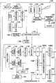
- FIG. 4is a diagram showing an example of a radio modulator and demodulator or modem of the video processing apparatus 100 ;
- FIG. 5is a block diagram showing an example of a system in which two video processing apparatuses are wirelessly connected to each other;
- FIG. 6is a block diagram showing another example of a system in which two video processing apparatuses are wirelessly connected to each other;
- FIG. 7is a diagram showing an example of structure of the HDMI
- FIG. 8is a diagram showing an example of a radio modem of the video display apparatus
- FIG. 9shows a diagram showing an example of transmission parameters of a radio modem in the embodiment.
- FIG. 10is a diagram showing connections between the video processing apparatus 100 and the video display apparatus 200 in the embodiment of the present invention.
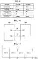
- FIG. 11is a diagram showing an example of assignment of bands in another example of a radio modem shown in FIGS. 4 and 8 .
- FIG. 10shows an embodiment of the present invention.
- the systemincludes two video processing apparatuses, i.e., a video processing apparatus 100 which is, for example, a portable video processing apparatus capable of receiving a digital broadcast signal via a base station antenna for cellular phones or a broadcast transmission tower and a video display apparatus 200 such as a tuner capable of receiving a digital broadcast signal from a broadcast transmission tower.
- a video processing apparatus 100which is, for example, a portable video processing apparatus capable of receiving a digital broadcast signal via a base station antenna for cellular phones or a broadcast transmission tower and a video display apparatus 200 such as a tuner capable of receiving a digital broadcast signal from a broadcast transmission tower.
- These apparatusesare connected, for example, via a bidirectional interface 10 to each other. Resultantly, a video signal of high picture quality and other information items and signals can be bidirectionally communicated therebetween.
- a terminal 134 of the video processing apparatus 100 and a terminal 202 of the video display apparatus 200signals from the internet and a home network are communicated by radio.
- the frequency bands used for the transmission between the terminals 134 and 202are limited to predetermined frequency bands. This increases the radio wave resource efficiency and prevents the problem of interference with other apparatuses.
- the portable video processing apparatus 100is specifically, for example, a digital camera, a video camera, a cellular phone, a game machine, or a personal media player.
- FIG. 1shows a concrete example of the video processing apparatus 100 employed in the first embodiment of the present invention. This is a specific configuration of the apparatus 100 shown in FIG. 10 .
- an imaging device 110receives a moving or still picture supplied via an optical system to convert the picture into en electric signal.
- a compression circuit 111employs a compression method, e.g., Moving Picture Experts Group 2 (MPEG2), MPEG4, or AVC/H.264.
- MPEG2Moving Picture Experts Group 2
- MPEG4MPEG4
- AVC/H.264AVC/H.264
- JPEGJoint Photographic Experts Group
- a microphone 112converts sound into an electric signal.
- a compression circuit 113uses a compression method such as an MPEG audio to efficiently bit-compress the received audio signal.
- a multiplexer circuit 116receives the bit-compressed video and audio signals from the compression circuits 111 and 113 and various information items from a microprocessor 115 . By use of the information items, the multiplexer 116 multiplexes the signals according to a predetermined format. When a still picture is shot, the audio signal is not obtained in an ordinary case. However, it is also possible to multiplex an audio signal in synchronism with the still picture shooting operation.
- the information items from the microprocessor 115include, for example, positional information (horizontal positions, vertical positions on the right, and vertical positions on the left), date, and exposure information at shooting.
- the multiplexed signal from the multiplexer 116is fed via an encryption/decryption circuit 140 to be stored in a storage 130 .
- the storage 130may be, for example, a hard disk device, an optical disk device, or a semiconductor memory device.
- the type of the storage 130may be determined according to, for example, a storage capacity, a size of the storage 130 , easiness of removing a storage medium, and/or a price of the storage 130 according to necessity. It is also possible to store the multiplexed signal via a signal processing circuit 124 and a memory interface 120 in a memory 121 .
- the video processing apparatus 100may also support the use of a removable memory or include a cellular phone function or a radio Local Area Network (LAN) function.
- the memory interface 120is an interface for a removable memory 121 . When video and audio contents of still and moving pictures are recorded by another apparatus in the memory 121 and the memory 121 is connected to the interface 120 , the contents can be recorded via the signal processing circuit 124 and the encryption/decryption circuit 140 into the storage 130 .
- the signal processing circuit 124checks to determine whether or not the copyright of the contents recorded in the memory 121 is protected and whether or not the duplication thereof is prohibited. According to the detected condition, the encryption/decryption circuit 140 encrypts the contents and moves the encrypted contents in the storage 130 .
- audio and video contents of still and moving picturesare received as inputs by a radio interface 122 .
- the contentsare stored via the signal processing circuit 124 and the encryption/decryption circuit 140 in the storage 130 . Also, according to conditions of the copyright protection and the replication restriction, the contents are encrypted by the encryption/decryption circuit 140 , as required.
- the userselects the content by an input key or a remote control, not shown.
- the selected contentis read from the storage 130 to be decoded by the encryption/decryption circuit 140 and is then separated by a demultiplexer circuit 141 into an audio signal and a video signal.
- the encrypted signal encrypted for the broadcastis decrypted by the encryption/decryption circuit 140 . If encryption is required to store the signal, the signal is accordingly encrypted by the circuit 140 to be stored in the storage 130 and the memory 121 . To immediately view the received broadcast program in real time, the signal is separated by the demultiplexer 141 into a video signal and an audio signal.
- the separated and compressed video signalis decompressed by a decompression circuit 142 to be fed to a signal processing circuit 150 .
- the circuit 150conducts a scanning-line conversion for the video signal on the basis of the number of scanning lines of a display 160 to output the resultant video signal to the display 160 .
- the separated and compressed audio signalis decompressed by a decompression circuit 143 to be delivered to an audio output device 161 . Since the video processing apparatus 100 includes the display 160 and the audio output device 161 , it is possible to immediately view the broadcast program without externally connecting any video display apparatus.
- the audio signalis advanced in time relative to the video signal, the user particularly perceives an uncomfortable feeling.
- the audio signalis delayed, for example, in the decompression processing, namely, a lip-sync operation is carried out. This removes the uncomfortable feeling due to the difference in time between the video and audio signals.
- a voice of a conversationis inputted to the audio input/output section 126 to produce an electric signal.
- a telephone signal processing circuit 125executes predetermined signal processing and modulation processing.
- the resultant signalis transmitted via an antenna, not shown, to a base station of the cellular phone.
- An audio signal sent from the base stationis received by an antenna, not shown, to be fed to the telephone signal processing circuit 125 .
- the circuit 125executes predetermined signal processing and demodulation processing.
- the resultant signalis fed to the audio I/O section 126 to be reproduced as a voice.
- the video processing apparatus 100can also receive a content of a moving picture transmitted from the base station of the cellular phone.
- the contentis received by an antenna, not shown, to be delivered via the telephone signal processing circuit 125 to the signal processing circuit 124 .
- the contentis similarly processed as above by the encryption/decryption circuit 140 .
- the resultant signal of the contentis fed to a display and an audio output unit incorporated in the video processing apparatus 100 to be viewed/listened by the user.
- the content thus processedmay also be fed via a terminal 101 , a connection cable 10 , and a terminal 201 to an external video display apparatus 200 to be displayed on a large-sized screen.
- While viewing the contentit is possible to record the content in a recording medium incorporated in the video processing apparatus 100 or a recording medium, e.g., a memory 121 connected thereto, for example, to view the content later.
- the memory 121may also be used as a recording medium to record a movie and the like.
- a program broadcast from a broadcast transmission toweris received by a broadcast receiver 180 of the video processing apparatus 100 to be viewed by the apparatus 100 or to be stored in a recording medium, not shown, incorporated in the apparatus 100 or a recording medium, e.g., the memory 121 connected thereto.
- the contentmay be fed via the terminal 101 , the cable 10 , and the terminal 201 to the video display apparatus 200 to be viewed by the user.
- an imaging device 110 and a microphone 112in the video processing apparatus 100 , still and moving pictures can be shot together with audios and can be stored in an incorporated recording medium, not shown, and/or the memory 121 .
- the videos and audios stored in the recording medium and/or the memory 121may be fed via the terminal 101 to the video display apparatus 200 to be enjoyed by the user.
- the apparatus 200confirms scanning lines which the apparatus 200 can support. If the scanning lines match those of the video signals to be displayed, the signals are immediately outputted in real time. Otherwise, the scanning lines of the video signals are converted by a signal processing circuit 150 into the required scanning lines to be fed to a multiplexer circuit 170 .
- the video signalsare multiplexed on the time axis, with the audio signals processed by a signal processing circuit 151 .
- the circuit 151compresses the audio signals on the time axis during a period corresponding to the blanking period of the video signals and conducts a time adjusting operation to carry out the lip-sync operation according to the necessity.
- the video and audio signals multiplexed by the multiplexer circuit 170are delivered to an encryption circuit 171 .
- the circuit 171carries out encryption for the transmission of the signals between the video processing apparatus 100 and the video display apparatus 200 and outputs the resultant signals via a video interface circuit 131 , a transmission rate assignment controller 1001 , and the terminal 101 to the video display apparatus 200 .
- the terminal 134is connected to a network such as the internet as described above and is used to wirelessly communicate videos and other information items obtained from the network by use of a radio modem circuit 1003 .
- the information from the networkis demodulated by the circuit 1003 to be fed via the transmission rate assignment controller 1001 to an interface circuit 133 and is delivered therefrom to a microprocessor 115 .
- the microprocessor 115determines the type of the information from the network. If the information is, for example, a video stream compressed in a predetermined format, the microprocessor 115 feeds the video stream to the demultiplexer circuit 141 and the decompression circuit 143 . For the video stream, the circuits 141 and 143 conduct processing as described above. The resultant signals are presented on the display 160 . According to necessity, the audio information obtained from the network is reproduced by the audio output device 161 .
- the microprocessor 115executes addition and storage processing for new software or executes update processing for the associated program.
- the processing of the network informationis executed by the microprocessor 115 to process video information in the embodiment, it is also possible to arrange a microprocessor to dedicatedly process the network information.
- the controller 132controls the transmission rate assignment control circuit 1001 on the basis of time control information of the video signal to variably control the transmission rate of the radio modem circuit 1002 .
- the controller 132variably controls the transmission rate of the radio modem circuit 1003 for radio communication with a network such as the Internet.
- the controller 132gives preference to the demodulation circuit 1002 .
- the transmission rate of the demodulation circuit 1002is more than that of the modem circuit 1003 .
- the modem 1002can transmit video information without deteriorating the video quality of the video information having high picture quality.
- the band of radio signals from the terminal 101 and that of radio signals from the terminal 134are fixed. Therefore, if the band of signals from the terminal 101 is expanded, that of signals from the terminal 134 narrows to slightly lower the communication speed of the network. However, this rarely influences the system operation since information regarding the network is less frequently exchanged as compared with video information sent from the video processing apparatus 100 .
- the encryption/decryption circuit 140delivers the compressed signal to the encryption circuit 171 .
- the circuit 171conducts predetermined encryption for the signal and then outputs the resultant signal via the video interface circuit 131 , the transmission rate assignment controller 1001 , and the terminal 101 .
- the control circuit 132variably controls the transmission rate of the radio modem 1002 in association with the time control information of the video signal. As a result, the radio modem 1002 can send the video information without deteriorating the video quality of the video information having high picture quality.
- the video and audio signals obtained from the imaging device 110 and the microphone 112 and the contents inputted from the memory 121 and the radio interface 122are once stored in the storage 130 to be thereafter reproduced.
- the signals and the contentsare demultiplexed by the demultiplexer 141 without conducting the encryption and decryption for the storage by the encryption/decryption circuit 140 .
- the videos and audioscan be enjoyed by use of the display 160 and the audio output device 161 of the video processing apparatus 100 .
- the modem circuits 1002 and 1003conduct demodulation through Orthogonal Frequency Division Multiplexing (OFDM).
- the modem 1002is a first radio communication unit which wirelessly sends video information and audio information to the external video display apparatus 200 and which receives data and information by radio therefrom.
- the modem 1002is connected via the transmission rate assignment controller 1001 to the interface circuit 131 which communicates with the video display apparatus 200 .
- the modem 1003is a second radio communication unit which connects to (accesses) a network, e.g., the Internet or a home network to wirelessly communicate various information including video signals, audio signals, and data therewith.
- the modem 1003is connected via the transmission rate assignment controller 1001 to the interface circuit 133 for networks.
- the controller 1001variably controls, according to a control signal from the controller 132 , the transmission rates respectively of the modems 1002 and 1003 by variably setting the modulation/demodulation methods, the frequency bands, and the number of carriers respectively for the modems 1002 and 1003 .
- the controller 132controls distribution of the radio transmission rate of each modem by controlling the transmission rate assignment controller 1001 .
- FIG. 9shows the difference in the transmission rate between two schemes.
- the controller 132 and the transmission rate assignment controller 1001control the radio transmission assignment such that the radio transmission rate of the modem 1002 to send the video information of high picture quality by radio to the video display apparatus 200 takes precedence over the radio transmission rate of the modem 1003 to connect to a network for communication. That is, the radio transmission rate of the modem 1002 is more than that of the modem 1003 .
- the controller 132controls the operation to continuously supply videos with high picture quality to the user, specifically, to set the transmission scheme of the modem 1002 to, for example, “scheme 1 ” shown in FIG. 9 .
- the controller 132sets the transmission scheme thereof to “scheme 2 ” of FIG. 9 .
- the transmission capacity of scheme 1is 17 Megabits per second (Mbps) which is more than three times that of scheme 2 (5 Mbps).
- MbpsMegabits per second
- 5 Mbps5 Mbps
- a higher transmission rateis assigned to the communication with the display apparatus 200 in the embodiment. It is hence possible that the user continuously views videos with high picture quality on the display apparatus 100 .
- the variable control of the transmission rateis not limited to the example shown in FIG. 9 .
- the controller 132 and the transmission rate assignment controller 1001may variably control the radio transmission assignment to the modems 1002 and 1003 in response to an indication from the user. For example, in a situation wherein the user issues an indication to transmit video information by radio via the modem 1002 to the display apparatus 200 while acquiring information from the Internet according to scheme 1 of FIG. 9 by use of the modem 1003 , the controller 132 outputs a control signal to the assignment controller 1001 such that the transmission scheme of the modem 1003 is changed from scheme 1 to scheme 2 of FIG. 9 and that of the modem 1002 is set to scheme 1 of FIG. 9 conduct communications.
- the transmission rate of the modem 1002may be variably changed according to fineness or precision of the video information sent from the modem 1002 to the display apparatus 200 .
- the controller 132instructs the assignment controller 1001 to heighten the transmission rate of the modem circuit 1002 . It is preferable in the operation that the transmission rate of the modem 1003 is lowered in association with the variable control of the transmission rate of the modem 1002 .
- the transmission rates of the radio modems 1002 and 1003may also be variably controlled by a communication technique using a plurality of antennas such as a Multi-Input Multi-Output (MIMO) scheme.
- MIMOMulti-Input Multi-Output
- FIG. 4shows only part of the system associated with the transmission rate assignment control.
- the same functional constituent components as those of FIG. 1are assigned with the same reference numerals.
- radio modem circuits 5001 to 5004are modems having respective fixed transmission capacity values and differ from each other only in the frequency band for transmission.
- the modems 5001 to 5004respectively have bands A to D as shown in FIG. 11 .
- Terminals 101 and 5005 to 5007are input terminals to receive signals and are arranged respectively for radio modems 5001 to 5004 .
- the modems 5001 to 5004may be appropriately combined with each other.
- the modems 5001 and 5002are employed to transmit video information and the modems 5003 and 5004 are utilized to communicate with the network such as the Internet.
- the interface circuit 131wirelessly transmits video information and audio information via the modems 5001 and 5002 to the video display apparatus 200
- the interface circuit 133conducts communication via the modems 5003 and 5004 with the network.
- the modems 5001 to 5003are assigned to send video information and only the modem 5004 is assigned to communicate with the network such as the Internet.
- the interface circuit 131transmits video and audio information by radio via the modems 5001 to 5003 to the display apparatus 200 , and the interface circuit 133 communicates with the network via the modem 5004 .
- the broadcast signalis required to be presented by synchronizing the time information sent from the broadcasting station with that on the receiver side. According to the present invention, the time information can be appropriately controlled without deteriorating the quality of the video information.
- FIG. 2shows a specific configuration of the video display apparatus 200 of FIG. 10 .
- the same constituent componentsare assigned with the same reference numerals and detailed description thereof will be avoided. Description will be given of a situation wherein an uncompressed baseband signal of a moving picture is inputted via the terminal 201 .
- the signal from the external video processing apparatus 100 thus received via the terminal 201is demodulated by a radio modem circuit 2015 to be supplied via a transmission rate assignment controller 2017 and an input/output interface circuit 2011 to a decryption circuit 211 .
- a controller 2013drives the assignment controller 2017 to vary the transmission rate of the modem 2015 according to that of the video information delivered from the video processing apparatus 100 .
- an input/output interface circuit 2011can receive the video information of high picture quality at preset timing.
- the decryption circuit 211is associated with encryption by the encryption circuit 171 shown in FIG. 1 and decrypts a signal encrypted by the circuit 171 .
- the decrypted signalis fed to a demultiplexer circuit 250 , and then video and audio signals obtained from the demultiplexer 250 are inputted to signal processing circuits 251 and 252 , respectively.
- the circuit 251conducts a scanning-line conversion and a resolution conversion according to the number of pixels displayable by a display 260 .
- the circuit 252decompresses on the time axis the audio signal which is compressed and multiplexed on the time axis by use of the blanking of the video signal.
- the circuit 252carries out the lip-sync operation and the sound quality adjustment. Signals outputted respectively from the circuits 251 and 252 are inputted respectively to a display 260 and an audio input/output unit 270 to be viewed by the user.
- the signal received from the terminal 201is delivered via the wired input/output interface circuit 2011 to the decryption circuit 211 .
- the circuit 211corresponds to the encryption circuit 171 shown in FIG. 2 and decrypts a signal encrypted by the circuit 171 .
- the decrypted signalis inputted to an encryption/decryption circuit 240 .
- the circuit 240reads copy control information of the content to be stored and encrypts the content for the storage thereof according to the information.
- the encrypted signalis stored in the storage 230 in the compressed state.
- a signal corresponding to a compressed signal decrypted by the encryption/decryption circuit 211is fed from the encryption/decryption circuit 240 to a demultiplexer circuit 241 .
- the signalis separated into a compressed video signal and a compressed audio signal.
- the separated video and audio signalsare decompressed respectively by decompression circuits 242 and 243 to baseband signals to be respectively supplied to the signal processing circuits 251 and 252 .
- Signals outputted respectively therefromare delivered respectively to the display and the audio output unit 270 to be viewed by the user.
- a content stored in the storage 230When a content stored in the storage 230 is reproduced to be viewed by the user, information items such as titles of the contents stored in the storage 230 are presented on the display 260 .
- a signal of the selected contentis fed from the storage 230 to the encryption/decryption circuit 240 .
- the circuit 240decrypts the encrypted signal of the content to input the resultant signal to the demultiplexer 241 .
- the signal of the contentis thereafter similarly processed as described above to be viewed by the user.
- the userselects one of the contents stored in a memory 221 to view the content.
- the selected contentis transferred via a memory interface 220 and a signal processing circuit 224 to the encryption/decryption circuit 240 .
- the circuit 224executes processing necessary to read the content from the memory 221 to input compressed and multiplexed video and audio signals of the content to the circuit 240 .
- Subsequent signal processingis similar to the processing executed after the content is read from the storage 230 .
- the content encrypted by the encryption/decryption circuit 240is stored via the signal processing circuit 224 and the memory interface 220 into the memory 221 .
- the systemexecutes processing in a similar way.
- a compressed content received by radiois fed via a radio interface 222 and the signal processing circuit 224 to the encryption/decryption circuit 240 .
- the circuit 240decrypts the signal encrypted for the radio transmission. Subsequent processing is similar to the processing executed at reproduction of the signal from the storage 230 .
- the content inputted from the terminal 201is transferred via the input/output interface 2011 , the decryption circuit 211 and the demultiplexer circuit 250 to be separated into a video signal and an audio signal.
- the video and audio signals thus separatedare fed via a replication control circuit 280 to compression circuits 281 and 282 .
- the circuit 280reads, from the content, multiplexed replication control information to determine whether or not replication of the content is allowed.
- As the control informationa bit may be assigned to a designated field. Or, by using electronic watermark, the information may be superimposed onto video or audio information.
- Information inputted from the network to the terminal 202is also processed in a similar fashion as above.
- the compression circuit 281compresses the video signal by use of a compression scheme, e.g., MPEG2, MPEG4, or AVC/H.264.
- the compression circuit 282compresses the audio signal according to a compression scheme, e.g., MPEG Audio.
- the compressed video and audio signalsare inputted to a multiplexer circuit 283 to be multiplexed.
- the multiplexed signalis fed to the encryption/decryption circuit 240 to be thereafter similarly stored in the storage 230 and/or the memory 221 .
- the contentcan be efficiently recorded therein for a long period of time according to copyright information.
- the signal from a network such as the Internet received via the terminal 202is demodulated by a radio modem circuit 2016 to be supplied via a transmission rate assignment controller circuit 2017 and an input/output interface circuit 2012 to a microprocessor 279 .
- the type of information of the video information from the networkis determined. If the information is, for example, a video stream compressed in a predetermined format, the system transfers the information to demultiplexer circuit 241 and the decompression circuits 242 and 243 . After the information is processed by these circuits in a similar way as described above, an image of the information is presented on the display 260 . According to necessity, audio information obtained from the network is reproduced by the audio output unit 261 .
- the microprocessor 279adds and stores new software and/or updates an associated program. It is also possible that the function of the microprocessor 279 is installed in the controller 2013 to configure one unified module including the microprocessor 279 and the controller 2013 .
- the controller 2013controls the transmission rate assignment controller 2017 to vary the transmission rate of the radio modem 2015 in association with the transmission rate of the video information received from the video processing apparatus 100 . Since the transmission rate of the radio modem 2015 to receive the video information from the apparatus 100 takes precedence over that of the modem 2016 in the transmission rate assignment, the transmission rate of the modem 2016 is lower than that of the modem 2015 . In the embodiment as described above, the transmission rate of the modem 2015 to receive the video information from the apparatus 100 is higher than that of the modem 2016 to communicate with the network. Therefore, within the limited range of bands for the radio transmission, it is possible to obtain the high-quality video information from the external video processing apparatus 100 without deteriorating the video quality.
- the band of radio signals received by the terminal 201 and that of radio signals inputted to the terminal 202are fixed. Hence, if the band of signals from the terminal 201 is expanded, that of signals from the terminal 202 narrows. This slightly lowers the communication speed of the network. However, this rarely influences the system operation since information regarding the network is less frequently exchanged as compared with video information sent from the video processing apparatus 100 .
- the modems 2015 and 2016carry out OFDM modulation/demodulation.
- the modem 2015is a first radio communication unit which wirelessly receives video information and audio information from the external video processing apparatus 100 and which sends data and information by radio to the apparatus 100 .
- the modem 2015is connected via the transmission rate assignment controller 2017 to the interface circuit 2011 which communicates with the video display apparatus 200 .
- the modem 2016is a second radio communication unit which connects to (accesses) a network, e.g., the Internet or a home network to wirelessly communicate various information including video signals, audio signals, and data with the network.
- the modem 2016is connected via the transmission rate assignment controller 2017 to the interface circuit 2012 for networks.
- the controller 2017variably controls, according to a control signal from the controller 2013 , the transmission rates respectively of the modems 2015 and 2016 by variably designating the modulation/demodulation methods, the frequency bands, and the number of carriers respectively for the modems 2015 and 2016 .
- the controller 2013controls distribution of the radio transmission rate of each modem by controlling the transmission rate assignment controller 2017 .
- FIG. 9shows the difference in the transmission rate between two schemes.
- the controller 2013 and the transmission rate assignment controller 2017control the radio transmission rate assignment so that the radio transmission rate of the modem 2015 to receive the video information of high picture quality by radio from the external video processing apparatus 100 takes precedence over the radio transmission rate of the modem 2016 to connect to a network for communication.
- the radio transmission rate of the modem 2015is more than that of the modem 2016 .
- the controller 2013controls the operation to continuously provide videos with high picture quality to the user, specifically, to set the transmission scheme of the modem 2015 to, for example, “scheme 1 ” shown in FIG. 9 .
- the controller 2013sets the transmission scheme thereof to “scheme 2 ” shown in FIG. 9 .
- the transmission capacity of scheme 1is 17 Mbps which is more than three times that of scheme 2 (5 Mbps).
- a higher transmission rateis assigned to the communication with the video processing apparatus 100 in the embodiment. It is therefore possible that the user continuously watches videos with high picture quality on the display apparatus 100 .
- the variable control of the transmission rateis not limited to the example shown in FIG. 9 .
- the controller 2013 and the transmission rate assignment controller 2017may control the radio transmission assignment to the modems 2015 and 2016 in response to an indication from the user. For example, in a situation wherein the user issues an indication to receive video information by radio via the modem 2015 from the video processing apparatus 100 while acquiring information from the Internet according to scheme 1 of FIG. 9 by use of the modem 2016 , the controller 2013 outputs a control signal to the assignment controller 2017 such that the transmission scheme of the modem 2016 is changed from scheme 1 to scheme 2 of FIG. 9 and that of the modem 2015 is set to scheme 1 of FIG. 9 .
- the transmission rate of the modem 2015may be changed according to precision of the video information which is sent from the video processing apparatus 100 to be received by the modem 2015 .
- the controller 2013instructs the assignment controller 2017 to heighten the transmission rate of the modem circuit 2015 . It is preferable in the operation that the transmission rate of the modem 2016 is lowered in association with the variable control of the transmission rate of the modem 2015 .
- the transmission rates of the radio modems 2015 and 2016may also be variably controlled by a communication technique using a plurality of antennas such as the MIMO scheme.
- FIG. 8shows only part of the system associated with the transmission rate assignment control.
- the same functional constituent components as those of FIG. 1are assigned with the same reference numerals.
- a transmission rate assignment controller 9005operates in a similar way as the transmission rate assignment controller 1001 described above and assigns transmission rates respectively to radio modems 9010 to 9013 according to an instruction from the controller 2013 .
- the modem circuits 9010 to 9013are modems having respective fixed transmission capacity values and differ from each other only in the frequency band for transmission.
- the modems 9010 to 9013respectively have bands A to D as shown in FIG. 11 .
- Terminals 9006 and 9007are input terminals to receive signals and are arranged respectively for radio modems 9010 to 9013 . In operation, the modems 9010 to 9013 may be appropriately combined with each other.
- the modems 9010 and 9011are employed to transmit video information and the modems 9012 and 9013 are utilized for communication with the network such as the Internet depending on cases. That is, while the interface circuit 2011 transmits by radio video information and audio information via the modems 9010 and 9011 to the video display apparatus 200 , the interface circuit 2012 communicates via the modems 9012 and 9013 with the network. In a situation wherein a wide band is required to receive video information of high picture quality (e.g., video information of HD resolution) from the video processing apparatus 100 , the modems 9010 to 9012 are allocated to transmit video information and only the modem 9013 is allocated to communicate with the network such as the Internet.
- high picture qualitye.g., video information of HD resolution
- the interface circuit 2011transmits video and audio information by radio via the modems 9010 to 9012 to the video display apparatus 200 , and the interface circuit 2012 communicates with the network via the modem 9013 .
- video information of high picture qualitycan be continuously transmitted and it is also possible to communicate with the Internet.
- the broadcast signalis required to be presented by synchronizing the time information sent from the broadcasting station with that on the receiver side. According to the embodiment, the time information can be appropriately controlled without deteriorating the quality of the video information.
- FIG. 7shows an example the HDMI configuration mainly including a transmission side and a reception side.
- the transmission sideincludes a transmitter section 1601 and a transmission controller section 1603 to control the transmitter section 1601 .
- the transmitter section 1601encodes a video signal (Y, Pb, Pr) and an audio signal to output resultant signals to a receiver section 1604 .
- the transmitter section 1601includes a TMDS encoder circuit 1602 which converts the video signal (Y, Pb, Pr) and the audio signal respectively into serial video data and serial audio data.
- the reception sideincludes a receiver section 1604 and a reception controller section 1606 to control the receiver section 1604 .
- the receiver section 1604receives the video data and the audio data from the transmitter section 1601 and conducts a TMDS decoding operation for the data by a TMDS decoder circuit 1605 to thereby reproduce baseband video data and baseband audio data.
- a CEC line 1607is an apparatus control line to transmit a control signal for apparatuses. Display specification information known as “DDC” is transmitted via a DDC line 1608 .
- the reception sidetransmits to the transmission side a Hot Plug Detect (HPD) signal 1609 indicating that a connection is established between apparatuses of the transmission and reception sides.
- HPDHot Plug Detect
- a physical addressis obtained via the DDC line.
- the physical addressis an identification number to discriminate an associated apparatus.
- a logical addressis obtained for bidirectional communication of each apparatus.
- the logical addressis identification information defining a category of each apparatus, e.g., a display or a recording apparatus.
- FIG. 5is a diagram to supplementally explain a radio interface 11 between the video processing apparatus 100 and the video display apparatus 200 .
- the apparatuses 100 and 200are almost the same as those described in conjunction with, for example, FIG. 1 .
- the radio interface circuit 133is shown in FIG. 8 and the other constituent components are not shown.
- the radio input/output interface circuit 2012is shown and the other constituent components are not shown.
- the interface circuits 133 and 2012are bidirectional interfaces.
- a channel between antennas 81 and 84 and a channel between antennas 82 and 85are channels to bidirectionally transmit a video signal, an audio signal, and control signals indicating copyright protection and a replication restriction condition of contents.
- a channel between antennas 83 and 86is disposed to transmit an inter-apparatus control signal.
- Bit selection circuits 811 and 812receive the video signal, the audio signal, the control signals indicating copyright protection and a replication restriction condition of contents, and the inter-apparatus control signal.
- the QPSK demodulation schemeis more resistive against transmission errors as compared with the 64QAM demodulation scheme.
- the 64QAM demodulation schemeis superior to the QPSK demodulation scheme.
- the video processing apparatus 100determines, by a carrier detector circuit, not shown, a state of an associated transmission path, i.e., whether or not the channel is reserved for another apparatus.
- a carrier detector circuitnot shown
- a checkis made to determine whether or not a carrier is detected in a predetermined frequency band for a predetermined period of time. If it is detected by the detector that the channel is occupied by another apparatus, the check is again carried out after a lapse of a predetermined period of time to determine whether or not an available channel is present. If such available channel is present, the condition is notified to the microprocessor 115 of the video processing apparatus 100 .
- the microprocessor 115outputs from a QPSK modem circuit 803 a channel use request signal as an inter-apparatus control signal to secure the channel use right. Thereafter, the microprocessor 115 sends a transmission request signal to a bit selection circuit 811 .
- An error control circuit 843adds an error control bit for error detection and correction to the transmission request signal and then transfers the signal to the QPSK modem 803 .
- the modem 803conducts a QPSK modulation for the signal to resultantly transmit a radio signal via the antenna 83 to the display apparatus 200 .
- the apparatus 200then receives the radio signal by the antenna 86 , carries out a QPSK demodulation for the signal by a QPSK modem 806 , conducts error detection and correction control for the demodulated signal by an error control circuit 847 to produce an inter-apparatus control signal, and delivers the signal to the bit selection circuit 812 .
- the microprocessor in the video display apparatus 200decodes the inter-apparatus control signal and receives the transmission request signal from the video processing apparatus 100 together with apparatus category information regarding the apparatus 100 (information to identify a category indicating whether the associated apparatus is a display apparatus or a recording apparatus) and an apparatus identification number of the apparatus 100 .
- apparatus category information regarding the apparatus 100information to identify a category indicating whether the associated apparatus is a display apparatus or a recording apparatus
- An apparatus identification number of the apparatus 100An image to urge the user to determine whether or not a connection is established to the video processing apparatus 100 is presented on a display screen of the display apparatus 200 .
- the userindicates allowance for the connection by using an input device such as a remote controller of the display apparatus 200 .
- the apparatus category information and the identification number to identify each of the apparatusesare communicated to exchange information to observe the copyright protection and the replication restriction condition of the content. If there does not exist any problem, it is allowed that the apparatuses 100 and 200 are connected to each other. In a situation wherein the connection is meaningless, for example, each of the apparatuses 100 and 200 is an input or output dedicated unit or the copyright protection or the replication restriction condition of the content is not observed, the connecting operation is interrupted and an indication of the condition is displayed on the apparatuses 100 and 200 . Description will now be given of a situation wherein the copyright protection and the replication restriction condition of the content are observed.
- an error control circuit 841By using the video signal, the audio signal, and the control signal indicating the copyright protection and the replication restriction condition of the contents associated with the video and audio signals which are inputted to an interface circuit 172 , two bits are selected from the Most-Significant Byte (MSB) of the video signal so that error detection and correction control bits are added thereto by an error control circuit 841 and the resultant signal is fed to a QPSK modem circuit 801 .
- the modem circuit 801conducts a QPSK modulation for the signal and then transmits an associated radio signal from the antenna 81 .
- an error control circuit 842adds error detection and correction control bits to send the resultant signal to a 64QAM modem circuit 802 .
- the modem 802carries out a 64QAM modulation for the signal and resultantly transmits a radio signal from the antenna 82 .
- a QPSK modem circuit 804conducts a QPSK demodulation for the signal received via the antenna 84 and an error control circuit 845 carries out error control for the resultant signal to output two high-order bits of the video signal to the bit control circuit 812 .
- a 64QAM modem circuit 805conducts a 64QAM demodulation.
- an error control circuit 846carries out error control to output the obtained signal to the bit control circuit 812 .
- inter-apparatus control signalWhen an inter-apparatus control signal is sent in a downlink direction, i.e., from the video display apparatus 200 to the video processing apparatus 100 , the signal is fed from the bit selection circuit 812 via the error control circuit 847 to the QPSK modem circuit 806 to be demodulated.
- the demodulated signalis delivered from the antenna 86 .
- the video processing apparatus 100receives the signal by the antenna 83 to send the signal to the QPSK modem circuit 803 .
- the circuit 803conducts a QPSK demodulation.
- an error detection and correctionis carried out by the error control circuit 843 to feed the resultant signal to the bit selection circuit 811 .
- an inter-apparatus control signalis transmitted in an uplink direction, i.e., from the video processing apparatus 100 to the video display apparatus 200 , the signal is fed from the bit selection circuit 811 via the error control circuit 843 to the QPSK modem circuit 803 to be modulated.
- the modulated signalis outputted from the antenna 83 .
- the display apparatus 200receives the signal by the antenna 86 .
- the modem 806conducts a QPSK demodulation.
- the error control circuit 847conducts an error detection and correction to send the resultant signal to the bit selection circuit 812 .
- the transmission highly resistive against noisethere can be conducted the transmission highly resistive against noise with a relatively low transmission rate. That is, by using the fact that higher order bits of a video signal more strongly affect the picture quality, two bits are taken out from the video signal in order of MSB and a transmission path using the QPSK modulation is allocated to the information of these two bits, to thereby preventing deterioration of the picture quality.
- the transmission path using the QPSK modulationmay be allocated to important bits, e.g., two high-order bits of the audio signal.
- a higher-frequencyis less influential as compared with a lower-frequency component for the frequency component in the horizontal direction of the screen and that in the vertical direction thereof.
- the signalis subdivided into a lower-frequency component and a higher-frequency component so that the QPSK modulation is used for the lower-frequency component and the 64QAM modulation is employed for the higher-frequency component.
- the noise resistivitycan be increased for important information and the overall transmission capacity is secured.
- the signalis subdivided into a lower-frequency component and a higher-frequency component so that the QPSK modulation is used for the lower-frequency component and the 64QAM modulation is employed for the higher-frequency component.
- the noise resistivitycan be strengthened for desired important information.
- the error control circuits 841 to 843add the error control information items to the bits inputted respectively thereto.
- the bits inputted to the circuits 841 to 843are collectively treated as one word to add error control information to the word. This advantageously leads to a simplified configuration of the error control circuits.
- FIG. 6shows an example of the configuration to carry out the encryption in the system of FIG. 5 .
- the system shown in FIG. 6includes encryption/decryption circuits 821 to 826 , interface circuits 830 and 831 including encryption, and error control circuits 841 to 847 .
- the bit selection circuit 811selects predetermined bits as in the example shown in FIG. 5 .
- the error control circuits 841 and 842conduct error control.
- the encryption/decryption circuits 821 and 822respectively carry out encryption.
- the obtained signalsare inputted respectively to the QPSK modem circuit 801 and the 64QAM modem circuit 802 to be demodulated.
- the signals demodulated respectively by the circuits 801 and 802are delivered to the encryption/decryption circuits 824 and 825 to be decrypted.
- the decrypted signalsare fed to the bit selection circuit 812 and are therein bit-combined with each other.
- the number of bits to be transmittedis reduced, for example, by use of reversible arithmetic codes based on a statistic property.
- the received signalsare decrypted by the encryption/decryption circuits 824 to 826 .
- the reversible codes corresponding to the circuits 821 to 823are decoded to be fed to the error control circuits 845 to 846 for the error detection and correction thereof.
- the obtained signalsare fed to the bit selection circuit 812 to be bit-combined with each other. Since the transmission rate of the information to be transmitted can be lowered by combining the reversible codes as above, the signal can be more efficiently transmitted.
- AES128 bit encryptionin all encryption circuits for the encryption, it is possible to conduct the encryption with high safety for the protection of contents. Moreover, if the AES128 bit encryption is employed for the content encryption circuit 821 and the Data Encryption Standard (DES) encryption is used for the other encryption circuits, there can be easily constructed a system in which the protection of important contents and the processing efficiency are appropriately achieved.
- DESData Encryption Standard
- the operations of the video processing apparatus 100 and the video display apparatus 200 in FIG. 6are basically similar to those of the apparatuses 100 and 200 shown in FIG. 5 .
- the video processing apparatus 100determines the state of an associated transmission path, specifically, detects by a carrier detection circuit, not shown, whether or not the channel to be used is occupied by another apparatus.
- a carrier detection circuitnot shown
- a checkis made to determined whether or not a carrier is detected in a predetermined frequency band for a predetermined period of time. If it is detected by the detector that the channel is occupied by another apparatus, the check is again carried out after a lapse of a predetermined period of time to determine whether or not an available channel is present.
- the conditionis notified to the microprocessor 115 of the video processing apparatus 100 .
- the microprocessor 115outputs from the QPSK modem circuit 803 a channel use request signal as an inter-apparatus control signal to secure the channel use right. Thereafter, the microprocessor 115 sends a transmission request signal to a bit selection circuit 811 .
- the error control circuit 843adds error control bits for error detection and correction to the transmission request signal which is in turn encrypted by an encryption/decryption circuit 823 and then transferred to the QPSK modem 803 .
- the modem 803conducts a QPSK modulation for the signal to resultantly transmit a radio signal via the antenna 83 to the display apparatus 200 .
- the apparatus 200then receives the radio signal by the antenna 86 , carries out a QPSK demodulation for the signal by the modem 806 , and decrypts the signal by the encryption/decryption circuit 826 .
- the error control circuit 847conducts error detection and correction control to produce an inter-apparatus control signal and delivers the signal to the bit selection circuit 812 .
- the microprocessor in the video display apparatus 200decodes the inter-apparatus control signal and receives the transmission request signal from the video processing apparatus 100 together with apparatus category information regarding the apparatus 100 (information to identify a category indicating whether the associated apparatus is a display apparatus or a recording apparatus) and an apparatus identification number of the apparatus 100 .
- apparatus category information regarding the apparatus 100information to identify a category indicating whether the associated apparatus is a display apparatus or a recording apparatus
- An apparatus identification number of the apparatus 100An image to urge the user to determine whether or not a connection is established to the video processing apparatus 100 is presented on a display screen of the display apparatus 200 .
- the userindicates allowance for the connection by use of an input device such as a remote control of the display apparatus 200 .
- the apparatus category information and the identification number to identify each of the apparatusesare communicated to exchange information to observe the copyright protection and the replication restriction condition of the content. If there does not exist any problem, it is allowed that the apparatuses 100 and 200 are connected to each other. In a situation wherein the connection is meaningless, for example, each of the apparatuses 100 and 200 is an input or output dedicated unit or the copyright protection or the replication restriction condition of the content is not observed, the connecting operation is interrupted and the status is displayed on the apparatuses 100 and 200 . As above, in a situation wherein the copyright protection and the replication restriction condition of the content are observed, the connection is established to transmit video and audio signals from the video processing apparatus 100 to the video display apparatus 200 .
- FIG. 3shows a second embodiment of the present invention and is another configuration of the video display apparatus 200 shown in FIG. 1 .
- the configuration of FIG. 3is partially equal to that of FIG. 2 .
- the same constituent componentsare assigned with the same reference numerals, and detailed description thereof will be avoided.
- the apparatus 200 of FIG. 3includes a decryption circuit 212 , encryption/decryption circuits 245 and 290 , compression/transcoding circuits 291 and 292 , and copy control circuit 293 which is a multiplexing circuit.
- each of the compression/transcoding circuits 291 and 292operates as a compression circuit for the baseband signal.
- the signalis fed via the input/output interface 210 to the encryption/decryption circuit 212 to be decrypted.
- the signalis then delivered to the demultiplexer circuit 250 to be separated into a compressed video signal and a compressed audio signal.
- the replication control circuit 290determines allowance or rejection of replication of the signals based on information indicating a replication restriction condition.
- the bit rates of the compressed video and audio signalsare lowered by the compression/transcoding circuits 291 and 292 by using, for example, a compression method having high compression efficiency according to necessity.
- Output signals from the circuits 291 and 292are multiplexed by the multiplexer circuit 293 to be inputted to the encryption/decryption circuit 245 .
- the circuit 245encrypts the input signal for the storage thereof to store the encrypted signals in the storage 230 and/or the memory 221 .
- the circuit 245decrypts the signal read from the storage 230 or the memory 221 , and the decrypted signal is separated by the demultiplexer circuit 241 into a video signal and an audio signal. Thereafter, these signals are processed in almost the same way as described above and the user resultantly enjoys the image and the sound.
- the signal from the multiplexer 293is delivered via the encryption/decryption circuit 245 to the demultiplexer 241 to be processed almost in the same way as above. In this case, it is possible to confirm the picture quality of the transcoded signal.
- the signalis fed from the decryption circuit 212 via the circuit 245 to the demultiplexer 241 to be separated into a video signal and an audio signal. Thereafter, the signals are processed in substantially the same way as described above.
- the signalcan be efficiently stored with a high compression ratio.
- the signal processingis carried out by use of circuits such as the compression circuits 111 and 113 in the embodiment, the circuits may be implemented by software means. In this situation, there can also be obtained similar advantages.
- the signal processingmay be accomplished in any appropriate fashion, that is, the present invention does not particularly limit how to implement the signal processing.
Landscapes
- Engineering & Computer Science (AREA)
- Signal Processing (AREA)
- Multimedia (AREA)
- Computer Networks & Wireless Communication (AREA)
- General Engineering & Computer Science (AREA)
- Computer Security & Cryptography (AREA)
- Two-Way Televisions, Distribution Of Moving Picture Or The Like (AREA)
- Small-Scale Networks (AREA)
- Mobile Radio Communication Systems (AREA)
- Controls And Circuits For Display Device (AREA)
Abstract
Description
Claims (28)
Priority Applications (1)
| Application Number | Priority Date | Filing Date | Title |
|---|---|---|---|
| US17/568,166US11445241B2 (en) | 2007-11-28 | 2022-01-04 | Information processing apparatus and information processing method |
Applications Claiming Priority (8)
| Application Number | Priority Date | Filing Date | Title |
|---|---|---|---|
| JP2007306750AJP5033598B2 (en) | 2007-11-28 | 2007-11-28 | Display device and video equipment |
| JP2007-306750 | 2007-11-28 | ||
| US12/260,410US9420212B2 (en) | 2007-11-28 | 2008-10-29 | Display apparatus and video processing apparatus |
| US15/208,886US10129590B2 (en) | 2007-11-28 | 2016-07-13 | Display apparatus and video processing apparatus |
| US15/891,085US10244284B2 (en) | 2007-11-28 | 2018-02-07 | Display apparatus and video processing apparatus |
| US16/269,662US11451860B2 (en) | 2007-11-28 | 2019-02-07 | Display apparatus and video processing apparatus |
| US16/738,059US11509953B2 (en) | 2007-11-28 | 2020-01-09 | Information processing apparatus and information processing method |
| US17/568,166US11445241B2 (en) | 2007-11-28 | 2022-01-04 | Information processing apparatus and information processing method |
Related Parent Applications (1)
| Application Number | Title | Priority Date | Filing Date |
|---|---|---|---|
| US16/738,059ContinuationUS11509953B2 (en) | 2007-11-28 | 2020-01-09 | Information processing apparatus and information processing method |
Publications (2)
| Publication Number | Publication Date |
|---|---|
| US20220132204A1 US20220132204A1 (en) | 2022-04-28 |
| US11445241B2true US11445241B2 (en) | 2022-09-13 |
Family
ID=40669376
Family Applications (10)
| Application Number | Title | Priority Date | Filing Date |
|---|---|---|---|
| US12/260,410Active2032-03-27US9420212B2 (en) | 2007-11-28 | 2008-10-29 | Display apparatus and video processing apparatus |
| US15/208,886Active2028-12-02US10129590B2 (en) | 2007-11-28 | 2016-07-13 | Display apparatus and video processing apparatus |
| US15/891,085ActiveUS10244284B2 (en) | 2007-11-28 | 2018-02-07 | Display apparatus and video processing apparatus |
| US16/269,662ActiveUS11451860B2 (en) | 2007-11-28 | 2019-02-07 | Display apparatus and video processing apparatus |
| US16/269,724ActiveUS11451861B2 (en) | 2007-11-28 | 2019-02-07 | Method for processing video information and method for displaying video information |
| US16/713,182ActiveUS10958971B2 (en) | 2007-11-28 | 2019-12-13 | Display apparatus and video processing apparatus |
| US16/738,059ActiveUS11509953B2 (en) | 2007-11-28 | 2020-01-09 | Information processing apparatus and information processing method |
| US17/568,166ActiveUS11445241B2 (en) | 2007-11-28 | 2022-01-04 | Information processing apparatus and information processing method |
| US17/967,092ActiveUS12143665B2 (en) | 2007-11-28 | 2022-10-17 | Information processing apparatus and information processing method |
| US18/905,664ActiveUS12418692B2 (en) | 2007-11-28 | 2024-10-03 | Information processing apparatus and information processing method |
Family Applications Before (7)
| Application Number | Title | Priority Date | Filing Date |
|---|---|---|---|
| US12/260,410Active2032-03-27US9420212B2 (en) | 2007-11-28 | 2008-10-29 | Display apparatus and video processing apparatus |
| US15/208,886Active2028-12-02US10129590B2 (en) | 2007-11-28 | 2016-07-13 | Display apparatus and video processing apparatus |
| US15/891,085ActiveUS10244284B2 (en) | 2007-11-28 | 2018-02-07 | Display apparatus and video processing apparatus |
| US16/269,662ActiveUS11451860B2 (en) | 2007-11-28 | 2019-02-07 | Display apparatus and video processing apparatus |
| US16/269,724ActiveUS11451861B2 (en) | 2007-11-28 | 2019-02-07 | Method for processing video information and method for displaying video information |
| US16/713,182ActiveUS10958971B2 (en) | 2007-11-28 | 2019-12-13 | Display apparatus and video processing apparatus |
| US16/738,059ActiveUS11509953B2 (en) | 2007-11-28 | 2020-01-09 | Information processing apparatus and information processing method |
Family Applications After (2)
| Application Number | Title | Priority Date | Filing Date |
|---|---|---|---|
| US17/967,092ActiveUS12143665B2 (en) | 2007-11-28 | 2022-10-17 | Information processing apparatus and information processing method |
| US18/905,664ActiveUS12418692B2 (en) | 2007-11-28 | 2024-10-03 | Information processing apparatus and information processing method |
Country Status (3)
| Country | Link |
|---|---|
| US (10) | US9420212B2 (en) |
| JP (1) | JP5033598B2 (en) |
| CN (3) | CN105407104B (en) |
Families Citing this family (12)
| Publication number | Priority date | Publication date | Assignee | Title |
|---|---|---|---|---|
| JP5033598B2 (en) | 2007-11-28 | 2012-09-26 | 株式会社日立製作所 | Display device and video equipment |
| JP5800553B2 (en)* | 2011-04-07 | 2015-10-28 | キヤノン株式会社 | Distribution device, video distribution method, and program |
| TWI583187B (en)* | 2013-07-30 | 2017-05-11 | 聯詠科技股份有限公司 | Data processing method and apparatus |
| CN105653569B (en)* | 2014-12-12 | 2019-04-05 | 航天恒星科技有限公司 | Image data extension processing method and device |
| US10400189B2 (en)* | 2015-12-28 | 2019-09-03 | Ronald J. Dobala | Gasoline engine lubricant |
| CN105847683A (en)* | 2016-03-31 | 2016-08-10 | 成都西可科技有限公司 | Motion camera one-key sharing system and method |
| JP7041559B2 (en)* | 2018-03-14 | 2022-03-24 | キヤノン株式会社 | Communication devices, data transfer devices and their control methods, and programs |
| US10873698B1 (en)* | 2019-06-17 | 2020-12-22 | Wipro Limited | Method and system for improving efficiency of optical camera communication |
| JPWO2021200410A1 (en)* | 2020-03-31 | 2021-10-07 | ||
| JP2023172239A (en)* | 2022-05-23 | 2023-12-06 | キヤノン株式会社 | Imaging device, accessory device, and communication control method |
| JP2023172241A (en) | 2022-05-23 | 2023-12-06 | キヤノン株式会社 | Imaging device, accessory device, and communication control method |
| WO2025135591A1 (en)* | 2023-12-19 | 2025-06-26 | Samsung Electronics Co., Ltd. | Method and system for prevention of hdmi cec line data drop by dynamic load sharing |
Citations (101)
| Publication number | Priority date | Publication date | Assignee | Title |
|---|---|---|---|---|
| US4561100A (en) | 1981-01-20 | 1985-12-24 | Sanyo Electric Co., Ltd. | Digital signal receiver |
| US5678173A (en) | 1994-05-19 | 1997-10-14 | Sanyo Electric Co., Ltd. | CATV system and method of judging modulation technique in CATV system |
| US5724355A (en) | 1995-10-24 | 1998-03-03 | At&T Corp | Network access to internet and stored multimedia services from a terminal supporting the H.320 protocol |
| US5758262A (en) | 1994-05-26 | 1998-05-26 | Econologic Technologies | Apparatus for converting TV audio signals for reception on a nearby AM and/or FM receiver |
| US5838384A (en) | 1995-07-17 | 1998-11-17 | Gateway 2000, Inc. | System for assigning multichannel audio signals to independent wireless audio output devices |
| JPH11187070A (en) | 1997-12-22 | 1999-07-09 | Mitsubishi Electric Corp | Communication control unit management method Communication priority setting system |
| US6037991A (en) | 1996-11-26 | 2000-03-14 | Motorola, Inc. | Method and apparatus for communicating video information in a communication system |
| WO2001093505A2 (en) | 2000-05-30 | 2001-12-06 | Soma Networks, Inc. | Communication structure with channels configured responsive to reception quality |
| CN1336768A (en) | 2000-07-17 | 2002-02-20 | 索尼公司 | Dual direction communication system, display device, base arrangement and dual direction communication method |
| KR20020016101A (en) | 2000-08-24 | 2002-03-04 | 박관우, 정창윤 | Apparatus for Internet phone using mobile terminals |
| JP2002135304A (en) | 2000-10-19 | 2002-05-10 | Sharp Corp | Wireless network system |
| EP1334617A2 (en) | 2000-11-14 | 2003-08-13 | Scientific-Atlanta, Inc. | Networked subscriber television distribution |
| US20030188322A1 (en) | 2002-03-28 | 2003-10-02 | General Instrument Corporation | Method and system for remotely displaying television program content using streaming video |
| US20030189638A1 (en) | 2002-04-09 | 2003-10-09 | Fry Terry L. | Narrow bandwidth, high resolution video surveillance system and frequency hopped, spread spectrum transmission method |
| US20040045030A1 (en) | 2001-09-26 | 2004-03-04 | Reynolds Jodie Lynn | System and method for communicating media signals |
| US20040048572A1 (en) | 2002-09-09 | 2004-03-11 | Godfrey Timothy Gordon | Multi-protocol interchip interface |
| US20040077313A1 (en) | 2001-09-13 | 2004-04-22 | Haruo Oba | Information processing apparatus and method |
| US20040107208A1 (en) | 1997-12-09 | 2004-06-03 | Seet Siew Shon | Method and apparatus for bookmarking telephone numbers for efficient access by wireless phone devices |
| US6763226B1 (en) | 2002-07-31 | 2004-07-13 | Computer Science Central, Inc. | Multifunctional world wide walkie talkie, a tri-frequency cellular-satellite wireless instant messenger computer and network for establishing global wireless volp quality of service (qos) communications, unified messaging, and video conferencing via the internet |
| US20040193647A1 (en) | 2001-07-10 | 2004-09-30 | Toru Ueda | Av data transmitter, av data receiver, and av data displaying/reproducing apparatus |
| US20040215769A1 (en) | 2003-04-24 | 2004-10-28 | Shikio Yoshida | Communication device and program and recording medium for the communication device |
| US20050034169A1 (en) | 2003-06-26 | 2005-02-10 | Satoru Maeda | Information processing system, information processing apparatus and method, recording medium, and program |
| CN1585403A (en) | 2004-05-27 | 2005-02-23 | 上海交通大学 | Service quality controlling method for light Internet network |
| CN1588997A (en) | 2004-06-30 | 2005-03-02 | 大唐微电子技术有限公司 | Display control deviced and method |
| US20050062945A1 (en) | 2002-09-13 | 2005-03-24 | Huang Shin-Pin | Projection device with wireless devices |
| US20050064860A1 (en) | 2003-09-05 | 2005-03-24 | Sony Ericsson Mobile Communications Ab | Remote control device having wireless phone interface |
| US20050130586A1 (en) | 2003-11-14 | 2005-06-16 | Cingular Wireless Ii, Llc | Personal base station system with wireless video capability |
| US20050136949A1 (en) | 2002-05-23 | 2005-06-23 | Barnes Melvin L.Jr. | Portable communications device and method of use |
| US20050144478A1 (en) | 2003-12-25 | 2005-06-30 | Kabushiki Kaisha Toshiba | Content receiving/storing apparatus and content delivery system |
| WO2005060127A1 (en) | 2003-12-19 | 2005-06-30 | Nokia Corporation | Selection of radio resources in a wireless communication device |
| US20050190747A1 (en) | 2004-02-27 | 2005-09-01 | Manoj Sindhwani | Multi-function telephone |
| US20050215284A1 (en) | 2004-03-26 | 2005-09-29 | Broadcom Corporation | Collaborative coexistence with dynamic prioritization of wireless devices |
| US20050227702A1 (en) | 2002-04-23 | 2005-10-13 | Sony Corporation | Radio communication method and radio communication device |
| US6957081B2 (en) | 2001-12-21 | 2005-10-18 | Motorola, Inc. | Multi-mode mobile communications device with continuous mode transceiver and methods therefor |
| US20050249245A1 (en) | 2004-05-06 | 2005-11-10 | Serconet Ltd. | System and method for carrying a wireless based signal over wiring |
| US20060025674A1 (en) | 2004-08-02 | 2006-02-02 | Kiraly Atilla P | System and method for tree projection for detection of pulmonary embolism |
| US20060097955A1 (en) | 2004-11-08 | 2006-05-11 | Kabushiki Kaisha Toshiba | Portable electronic device |
| US20060128425A1 (en) | 2004-12-13 | 2006-06-15 | Rooyen Pieter V | Method and system for mobile architecture supporting cellular or wireless networks and broadcast utilizing a multichip cellular and broadcast silicon solution |
| CN1791092A (en) | 2004-12-16 | 2006-06-21 | 国际商业机器公司 | System and method for connection capacity reassignment in a multi-tier data processing system network |
| US20060135076A1 (en)* | 2004-11-22 | 2006-06-22 | Nokia Corporation | Method and device for controlling radio access |
| US20060203758A1 (en)* | 2005-03-11 | 2006-09-14 | Samsung Electronics Co., Ltd. | Mobile terminal for relaying multimedia data to an external display device |
| WO2006098825A2 (en) | 2005-03-09 | 2006-09-21 | Sony Electronics, Inc. | System and method for dynamic bandwidth estimation of network links |
| EP1708467A1 (en) | 2005-03-29 | 2006-10-04 | Sony Ericsson Mobile Communications AB | Method for sharing information between handheld communication devices and handheld communication device therefore |
| US20060256747A1 (en) | 2005-05-16 | 2006-11-16 | Mikko Jaakkola | Terminal assisted WLAN access point rate adaptation |
| US20060258289A1 (en) | 2005-05-12 | 2006-11-16 | Robin Dua | Wireless media system and player and method of operation |
| US7146133B2 (en) | 2003-06-19 | 2006-12-05 | Microsoft Corporation | Wireless transmission interference avoidance on a device capable of carrying out wireless network communications |
| JP2006352522A (en) | 2005-06-16 | 2006-12-28 | Nissan Motor Co Ltd | Communication control device and communication control method |
| US20070006255A1 (en) | 2005-06-13 | 2007-01-04 | Cain David C | Digital media recorder highlight system |
| WO2007010444A1 (en) | 2005-07-22 | 2007-01-25 | Nxp B.V. | Method and device for operation of two wireless services |
| US20070021140A1 (en) | 2005-07-22 | 2007-01-25 | Keyes Marion A Iv | Wireless power transmission systems and methods |
| US20070072642A1 (en) | 2005-09-27 | 2007-03-29 | Tita Kangas | Mobile communication terminal and method |
| US20070070960A1 (en) | 2005-09-27 | 2007-03-29 | Amit Barak | Device, system, and method of multi-entity wireless communication adapter having a multi-channel mode |
| US20070085933A1 (en) | 2005-10-13 | 2007-04-19 | Funai Electric Co., Ltd. | Receiving apparatus and television receiver |
| US20070086724A1 (en) | 2002-07-17 | 2007-04-19 | Jeff Grady | Interface systems for portable digital media storage and playback devices |
| US20070091835A1 (en) | 2005-10-21 | 2007-04-26 | Samsung Electronics Co., Ltd. | Device and method to play back contents according to reception sensitivity |
| US20070094691A1 (en) | 2005-10-24 | 2007-04-26 | Gazdzinski Robert F | Method and apparatus for on-demand content transmission and control over networks |
| US20070109973A1 (en)* | 2005-03-09 | 2007-05-17 | Broadcom Corporation, A California Corporation | Co-location interference avoidance in multiple protocol communication networks |
| US7224964B2 (en) | 2000-08-23 | 2007-05-29 | Novatel Wireless, Inc. | Method and apparatus for distributed data transfer over multiple independent wireless networks |
| US20070123163A1 (en) | 2005-09-29 | 2007-05-31 | Kabushiki Kaisha Toshiba | Electronic device system, electronic device, display device, and communication control method of electronic device system |
| US7233359B2 (en) | 2002-12-13 | 2007-06-19 | Canon Kabushiki Kaisha | Image sensing apparatus having image signals generated from light between optical elements of an optical element array |
| CN1984481A (en) | 2006-05-18 | 2007-06-20 | 华为技术有限公司 | Method for guaranting telecommunication group service quality |
| WO2007069210A2 (en) | 2005-12-15 | 2007-06-21 | Nxp B.V. | Gsm harmonic emission desensitization in 5-ghz wlan |
| US20070165754A1 (en) | 2006-01-17 | 2007-07-19 | Niko Kiukkonen | Method for avoiding interference from a cellular transmitter to the 2.4/5GHz ISM band |
| US20070184785A1 (en) | 2006-02-08 | 2007-08-09 | Kabushiki Kaisha Toshiba | Radio communicator |
| JP2007202115A (en) | 2005-12-26 | 2007-08-09 | Matsushita Electric Ind Co Ltd | Address management method and communication device |
| WO2007091202A2 (en) | 2006-02-06 | 2007-08-16 | Koninklijke Philips Electronics N.V. | Hybrid wlan-gsm device synchronization to eliminate need for costly filters |
| US20070223505A1 (en) | 2006-03-22 | 2007-09-27 | Itai Kimio | Data transmission apparatus, data transmission method and data transmission system |
| US20070238482A1 (en) | 2006-03-30 | 2007-10-11 | Giora Rayzman | Device, system and method of coordination among multiple transceivers |
| US20070242313A1 (en) | 2006-04-11 | 2007-10-18 | Canon Kabushiki Kaisha | Digital camera and controlling method therefor |
| US20070265034A1 (en) | 2006-05-11 | 2007-11-15 | Mika Kasslin | Multiradio control interface element in modem |
| US20070275746A1 (en) | 2006-05-25 | 2007-11-29 | Altair Semiconductor | Multi-function wireless terminal |
| US20080025273A1 (en) | 2006-07-31 | 2008-01-31 | Fujitsu Limited | Communication apparatus, network apparatus, communication system, communication method, communication program, and recording medium |
| US20080081663A1 (en) | 2006-10-03 | 2008-04-03 | Nokia Corporation | System for managing radio modems |
| US20080101446A1 (en) | 2006-10-31 | 2008-05-01 | Motorola, Inc. | Multi-modem scheduling on a communication device |
| US20080109307A1 (en) | 2006-09-14 | 2008-05-08 | Shah Ullah | Methods and systems for securing content played on mobile devices |
| US20080139118A1 (en) | 2006-12-11 | 2008-06-12 | Sanguinetti Louie J | Wireless communications circuitry with simultaneous receive capabilities for handled electronic devices |
| WO2008072057A2 (en) | 2006-12-11 | 2008-06-19 | Nokia Corporation | Radio transmission scheduling according to multiradio control in a radio modem |
| US20080188182A1 (en) | 2007-02-06 | 2008-08-07 | Jeff Macholz | Entertainment system including selectable ir receive and transmit codes and day/night picture modes |
| US20080201751A1 (en) | 2006-04-18 | 2008-08-21 | Sherjil Ahmed | Wireless Media Transmission Systems and Methods |
| US20080229369A1 (en) | 2007-03-14 | 2008-09-18 | Lewis Scott W | Multimedia communicator utilized to offer open services |
| US20080291839A1 (en) | 2007-05-25 | 2008-11-27 | Harold Scott Hooper | Method and system for maintaining high reliability logical connection |
| US20080304431A1 (en) | 2007-06-11 | 2008-12-11 | Jeyhan Karaoguz | Method And System For A Digital Diary System |
| US20090091663A1 (en) | 2005-08-01 | 2009-04-09 | Nxp B.V. | Receiver for different types of reception signals |
| US20090103518A1 (en) | 2007-10-18 | 2009-04-23 | Motorola, Inc. | Call origination by an application server in an internet protogol multimedia core network subsystem |
| US7590075B2 (en) | 2005-04-15 | 2009-09-15 | Dell Products L.P. | Systems and methods for managing wireless communication |
| US7668565B2 (en) | 2006-11-07 | 2010-02-23 | Nokia Corporation | Multiradio priority control based on modem buffer load |
| US7787882B2 (en) | 2005-08-03 | 2010-08-31 | Kamilo Feher | Touch screen generated processed signals in multiple communication systems and networks |
| US7970350B2 (en) | 2007-10-31 | 2011-06-28 | Motorola Mobility, Inc. | Devices and methods for content sharing |
| US7978774B2 (en) | 2005-08-03 | 2011-07-12 | Kamilo Feher | Internet GSM, CDMA, OFDM, Wi-Fi wireless and wired multimode systems |
| US8045922B2 (en) | 2007-11-23 | 2011-10-25 | Texas Instruments Incorporated | Apparatus for and method of bluetooth and wireless local area network coexistence using a single antenna in a collocated device |
| US8050707B2 (en) | 2007-02-02 | 2011-11-01 | Dell Products L.P. | Method for selecting a priority for wireless technologies via graphical representation |
| US8073492B2 (en) | 2005-10-24 | 2011-12-06 | Broadcom Corporation | Simultaneously multi-networked handheld multimedia gateways |
| US8311509B2 (en) | 2005-08-03 | 2012-11-13 | Kamilo Feher | Detection, communication and control in multimode cellular, TDMA, GSM, spread spectrum, CDMA, OFDM WiLAN and WiFi systems |
| US8325237B2 (en) | 2005-12-30 | 2012-12-04 | Telecom Italia S.P.A. | Monitoring system for monitoring coverage of broadcast transmissions |
| US8572257B2 (en) | 2006-01-27 | 2013-10-29 | Robin Dua | Method and system to share media content between devices via near field communication (NFC) and wireless communication |
| US8625547B1 (en) | 2005-03-11 | 2014-01-07 | At&T Intellectual Property Ii, L.P. | Two-tier wireless broadband access network |
| US8693950B2 (en) | 2006-03-23 | 2014-04-08 | Broadcom Corporation | Method and system for transmit power control techniques to reduce mutual interference between coexistent wireless networks device |
| US8796046B2 (en) | 2011-02-14 | 2014-08-05 | Qualcomm Incorporated | Methods of integrated shielding into MTJ device for MRAM |
| EP1747616B1 (en) | 2004-05-17 | 2016-01-06 | Gula Consulting Limited Liability Company | Mobile terminal having uwb and cellular capability |
| US9344237B2 (en) | 2005-05-05 | 2016-05-17 | Iii Holdings 1, Llc | WiFi remote displays |
| US10129590B2 (en)* | 2007-11-28 | 2018-11-13 | Maxell, Ltd. | Display apparatus and video processing apparatus |
Family Cites Families (108)
| Publication number | Priority date | Publication date | Assignee | Title |
|---|---|---|---|---|
| US7207053B1 (en) | 1992-12-09 | 2007-04-17 | Sedna Patent Services, Llc | Method and apparatus for locally targeting virtual objects within a terminal |
| US5960344A (en) | 1993-12-20 | 1999-09-28 | Norand Corporation | Local area network having multiple channel wireless access |
| US5802463A (en) | 1996-08-20 | 1998-09-01 | Advanced Micro Devices, Inc. | Apparatus and method for receiving a modulated radio frequency signal by converting the radio frequency signal to a very low intermediate frequency signal |
| US6072768A (en) | 1996-09-04 | 2000-06-06 | Globalstar L.P. | Automatic satellite/terrestrial mobile terminal roaming system and method |
| EP0869628A1 (en) | 1997-04-01 | 1998-10-07 | ICO Services Ltd. | Interworking between telecommunications networks |
| US6621870B1 (en) | 1999-04-15 | 2003-09-16 | Diva Systems Corporation | Method and apparatus for compressing video sequences |
| US8266657B2 (en) | 2001-03-15 | 2012-09-11 | Sling Media Inc. | Method for effectively implementing a multi-room television system |
| US6990082B1 (en) | 1999-11-08 | 2006-01-24 | Intel Corporation | Wireless apparatus having a transceiver equipped to support multiple wireless communication protocols |
| US6609253B1 (en) | 1999-12-30 | 2003-08-19 | Bellsouth Intellectual Property Corporation | Method and system for providing interactive media VCR control |
| US7565680B1 (en) | 2000-06-30 | 2009-07-21 | Comcast Ip Holdings I, Llc | Advanced set top terminal having a video call feature |
| KR20020015848A (en) | 2000-08-23 | 2002-03-02 | 윤종용 | Television based on operating system and initial screen display method thereof |
| GB0108354D0 (en) | 2001-04-03 | 2001-05-23 | Thirdspace Living Ltd | System and method for providing a user with access to a plurality of sevices and content from a broadband television service |
| US6714760B2 (en) | 2001-05-10 | 2004-03-30 | Qualcomm Incorporated | Multi-mode satellite and terrestrial communication device |
| US8284739B2 (en) | 2001-05-24 | 2012-10-09 | Vixs Systems, Inc. | Method and apparatus for affiliating a wireless device with a wireless local area network |
| US6795972B2 (en) | 2001-06-29 | 2004-09-21 | Scientific-Atlanta, Inc. | Subscriber television system user interface with a virtual reality media space |
| US20030030720A1 (en) | 2001-08-10 | 2003-02-13 | General Instrument Corporation | Wireless video display apparatus and associated method |
| JP3600564B2 (en) | 2001-09-11 | 2004-12-15 | 株式会社東芝 | Portable information device having a plurality of wireless units |
| US7522551B2 (en) | 2001-09-17 | 2009-04-21 | Microsoft Corporation | Method and apparatus for wireless routing on a plurality of different wireless channels |
| US6801777B2 (en) | 2001-11-27 | 2004-10-05 | Intel Corporation | Device and method for intelligent wireless communication selection |
| US8707354B1 (en) | 2002-06-12 | 2014-04-22 | Tvworks, Llc | Graphically rich, modular, promotional tile interface for interactive television |
| JP2003333050A (en)* | 2002-05-10 | 2003-11-21 | Matsushita Electric Ind Co Ltd | Data transmission method |
| GB2391137B (en) | 2002-07-19 | 2004-09-01 | Synad Technologies Ltd | Method of controlling access to a communications medium |
| US20040204079A1 (en) | 2002-09-30 | 2004-10-14 | Compaq Information Technologies Group, L.P. | Dual access wireless LAN system |
| US7360235B2 (en) | 2002-10-04 | 2008-04-15 | Scientific-Atlanta, Inc. | Systems and methods for operating a peripheral record/playback device in a networked multimedia system |
| US20040203800A1 (en) | 2002-10-24 | 2004-10-14 | John Myhre | System and method for content delivery using alternate data paths in a wireless network |
| WO2004051906A2 (en) | 2002-11-27 | 2004-06-17 | Rgb Media, Inc. | Apparatus and method for dynamic channel mapping and optimized scheduling of data packets |
| JP2004208001A (en) | 2002-12-25 | 2004-07-22 | Sharp Corp | Wireless communication system, wireless communication method, wireless communication program, and program recording medium |
| US6873611B2 (en) | 2002-12-31 | 2005-03-29 | Nextwlan Corporation | Multiprotocol WLAN access point devices |
| JP3779683B2 (en) | 2003-01-16 | 2006-05-31 | 株式会社東芝 | Information processing apparatus and communication control method |
| JP2004222136A (en)* | 2003-01-17 | 2004-08-05 | Matsushita Electric Ind Co Ltd | Wireless communication system and access point control device |
| US7149508B2 (en) | 2003-02-05 | 2006-12-12 | Samsung Electronics Co., Ltd. | System and method for delta-based over-the-air software upgrades for a wireless mobile station |
| US7215660B2 (en) | 2003-02-14 | 2007-05-08 | Rearden Llc | Single transceiver architecture for a wireless network |
| US7593361B2 (en) | 2003-02-14 | 2009-09-22 | Onlive, Inc. | Method of operation for a three-dimensional, wireless network |
| GB0307694D0 (en) | 2003-04-03 | 2003-05-07 | Koninkl Philips Electronics Nv | Broadcast delivery to a wireless device |
| WO2004093404A1 (en) | 2003-04-17 | 2004-10-28 | Sharp Kabushiki Kaisha | Transmitter, receiver, wireless system, control method, control program, and computer-readable recording medium containing the program |
| JP3838237B2 (en) | 2003-04-30 | 2006-10-25 | ソニー株式会社 | Wireless communication system, transmitting apparatus and receiving apparatus |
| WO2004104773A2 (en) | 2003-05-15 | 2004-12-02 | Comcast Cable Holding, Llc | Method and system for playing video |
| US20040235515A1 (en) | 2003-05-20 | 2004-11-25 | Jesse Kao | Dual frequency wireless network access device |
| JP3683576B2 (en) | 2003-05-21 | 2005-08-17 | シャープ株式会社 | Wireless communication apparatus, wireless communication system, wireless AV system, wireless transmission method, operation control program, and recording medium recording the program |
| US20050020299A1 (en) | 2003-06-23 | 2005-01-27 | Quorum Systems, Inc. | Time interleaved multiple standard single radio system apparatus and method |
| US7403556B2 (en) | 2003-06-30 | 2008-07-22 | Via Technologies Inc. | Radio receiver supporting multiple modulation formats with a single pair of ADCs |
| US7236804B2 (en)* | 2003-07-15 | 2007-06-26 | Sr Telecom, Inc. | Method of supporting voice-band modem-to-modem calls in a wireless communication system |
| JPWO2005015764A1 (en) | 2003-08-11 | 2007-10-04 | ソニー株式会社 | Wireless communication system and wireless communication apparatus |
| JP4218463B2 (en) | 2003-08-11 | 2009-02-04 | ソニー株式会社 | Wireless communication apparatus and wireless communication system |
| DE60329790D1 (en) | 2003-12-01 | 2009-12-03 | Ericsson Telefon Ab L M | TRAFFIC CONTROL PROCEDURES |
| US7486337B2 (en) | 2003-12-22 | 2009-02-03 | Intel Corporation | Controlling the overlay of multiple video signals |
| US7562379B2 (en) | 2003-12-22 | 2009-07-14 | Sony Corporation | Method and system for wireless digital multimedia presentation |
| US7594109B2 (en) | 2003-12-23 | 2009-09-22 | Hewlett-Packard Development Company, L.P. | Digital content distribution system |
| US8132204B2 (en) | 2004-04-07 | 2012-03-06 | Visible World, Inc. | System and method for enhanced video selection and categorization using metadata |
| US7849064B2 (en) | 2004-04-23 | 2010-12-07 | Tvworks, Llc | Application programming interface combining asset listings |
| KR100630086B1 (en) | 2004-05-12 | 2006-09-27 | 삼성전자주식회사 | Device for receiving digital multimedia broadcasting from a mobile terminal |
| JP4685501B2 (en)* | 2004-07-07 | 2011-05-18 | 株式会社エヌ・ティ・ティ・ドコモ | Channel assignment method |
| US9031568B2 (en) | 2004-07-28 | 2015-05-12 | Broadcom Corporation | Quality-of-service (QoS)-based association with a new network using background network scanning |
| US7706326B2 (en) | 2004-09-10 | 2010-04-27 | Interdigital Technology Corporation | Wireless communication methods and components that implement handoff in wireless local area networks |
| TWM266655U (en) | 2004-09-23 | 2005-06-01 | Blueexpert Technology Corp | Bluetooth earphone device capable of wirelessly receiving and transmitting stereo sound signal and digital information signal |
| US7719567B2 (en)* | 2004-09-24 | 2010-05-18 | Smartvue Corporation | Wireless video surveillance system and method with emergency video access |
| US20060083194A1 (en) | 2004-10-19 | 2006-04-20 | Ardian Dhrimaj | System and method rendering audio/image data on remote devices |
| US9489496B2 (en) | 2004-11-12 | 2016-11-08 | Apple Inc. | Secure software updates |
| US8396508B2 (en) | 2004-12-13 | 2013-03-12 | Broadcom Corporation | Method and system for a mobile receiver architecture for European band cellular and broadcasting |
| US20060224763A1 (en) | 2005-03-18 | 2006-10-05 | Sharp Laboratories Of America, Inc. | Switching and simultaneous usage of 802.11a and 802.11g technologies for video streaming |
| US8909945B2 (en) | 2005-04-08 | 2014-12-09 | Interdigital Technology Corporation | Method for transmit and receive power control in mesh systems |
| KR100713279B1 (en) | 2005-04-18 | 2007-05-04 | 엘지전자 주식회사 | Apparatus and method for multi data transmission of video display equipment |
| KR100703327B1 (en) | 2005-04-19 | 2007-04-03 | 삼성전자주식회사 | Wireless Stereo Headset System |
| US20060240816A1 (en) | 2005-04-22 | 2006-10-26 | Marvell World Trade Ltd. | Wireless phone system |
| US20060274704A1 (en) | 2005-06-01 | 2006-12-07 | Prasanna Desai | Method and apparatus for collaborative coexistence between Bluetooth and IEEE 802.11 G with both technologies integrated onto a system-on-a-chip (SOC) device |
| JP5082209B2 (en)* | 2005-06-27 | 2012-11-28 | 株式会社日立製作所 | Transmission device, reception device, and video signal transmission / reception system |
| US20060292987A1 (en) | 2005-06-27 | 2006-12-28 | Lior Ophir | Method of wireless local area network and Bluetooth network coexistence in a collocated device |
| KR100724980B1 (en) | 2005-06-28 | 2007-06-04 | 삼성전자주식회사 | Dual-mode DMV terminal capable of receiving satellite DMV and terrestrial DMV simultaneously |
| US7634241B2 (en) | 2005-07-29 | 2009-12-15 | Broadcom Corporation | MIMO radio interfaces |
| US7953417B2 (en) | 2005-11-04 | 2011-05-31 | Qualcomm Incorporated | Methods and apparatus for selecting and signaling a preferred link among a plurality of maintained wireless communications links |
| US20070089158A1 (en) | 2005-10-18 | 2007-04-19 | Clark Christopher M | Apparatus and method for providing access to associated data related to primary media data |
| KR100676057B1 (en) | 2005-10-19 | 2007-01-30 | 엘지전자 주식회사 | Wireless LAN device capable of automatically changing channel according to wireless interference and its method |
| US8559525B2 (en) | 2005-10-21 | 2013-10-15 | Amimon Ltd. | Apparatus and method for uncompressed, wireless transmission of video |
| US20070093275A1 (en) | 2005-10-25 | 2007-04-26 | Sony Ericsson Mobile Communications Ab | Displaying mobile television signals on a secondary display device |
| US7653163B2 (en) | 2005-10-26 | 2010-01-26 | Intel Corporation | Systems for communicating using multiple frequency bands in a wireless network |
| US7409485B1 (en) | 2005-10-27 | 2008-08-05 | Cisco Technology, Inc. | Optimized data transfer for a data bus |
| US7626994B2 (en) | 2005-11-14 | 2009-12-01 | Broadcom Corporation | Multiple node applications cooperatively managing a plurality of packet switched network pathways |
| US8112513B2 (en) | 2005-11-30 | 2012-02-07 | Microsoft Corporation | Multi-user display proxy server |
| US20070124792A1 (en) | 2005-11-30 | 2007-05-31 | Bennett James D | Phone based television remote control |
| US9247175B2 (en) | 2005-11-30 | 2016-01-26 | Broadcom Corporation | Parallel television remote control |
| US20070136778A1 (en) | 2005-12-09 | 2007-06-14 | Ari Birger | Controller and control method for media retrieval, routing and playback |
| KR100754196B1 (en) | 2005-12-10 | 2007-09-03 | 삼성전자주식회사 | How to change content playback device during streaming playback and device therefor |
| US20070143806A1 (en) | 2005-12-17 | 2007-06-21 | Pan Shaoher X | Wireless system for television and data communications |
| US20070143801A1 (en) | 2005-12-20 | 2007-06-21 | Madonna Robert P | System and method for a programmable multimedia controller |
| US7941179B2 (en) | 2005-12-21 | 2011-05-10 | Broadcom Corporation | System and method providing concurrent multimode communication |
| FR2895869B1 (en) | 2005-12-29 | 2008-05-23 | Henri Seydoux | WIRELESS DISTRIBUTION SYSTEM OF AN AUDIO SIGNAL BETWEEN A PLURALITY OF ACTICAL SPEAKERS |
| KR100850577B1 (en) | 2006-01-27 | 2008-08-06 | 삼성전자주식회사 | Multi data processing device and method of mobile terminal |
| US7545787B2 (en) | 2006-02-09 | 2009-06-09 | Altair Semiconductor Ltd. | Simultaneous operation of wireless LAN and long-range wireless connections |
| US20070220150A1 (en) | 2006-03-01 | 2007-09-20 | Cypress Semiconductor Corp. | Source Switching Method for Multimedia Interface |
| US8023478B2 (en) | 2006-03-06 | 2011-09-20 | Cisco Technology, Inc. | System and method for securing mesh access points in a wireless mesh network, including rapid roaming |
| US20070266410A1 (en) | 2006-05-12 | 2007-11-15 | Palo Alto Research Center Incorporated | Access of data resources using pause points |
| US7738543B2 (en) | 2006-06-05 | 2010-06-15 | Lantiq Deutschland Gmbh | Methods and systems for determining communication parameters |
| US20070296822A1 (en) | 2006-06-09 | 2007-12-27 | Yin-Chun Blue Lan | Method and device for wireless video communication |
| US8307398B2 (en) | 2006-06-30 | 2012-11-06 | At&T Intellectual Property I, L.P. | Apparatus for receiving and displaying cellular television content and method for billing for same |
| US20080049707A1 (en) | 2006-07-12 | 2008-02-28 | Samsung Electronics Co., Ltd. | Transmission packet for wireless transmission in a high frequency band, and method and apparatus for transmission/receiving using the same |
| JP2008033138A (en) | 2006-07-31 | 2008-02-14 | Toshiba Corp | Video signal processing apparatus and video signal processing method |
| US20080040757A1 (en) | 2006-07-31 | 2008-02-14 | David Romano | Video content streaming through a wireless access point |
| JP4588005B2 (en) | 2006-09-14 | 2010-11-24 | シャープ株式会社 | Communication terminal device, video display device, and control program |
| US20090241149A1 (en) | 2006-09-19 | 2009-09-24 | Access Co., Ltd. | Content reproduction system, remote control device, and computer program |
| WO2008041232A2 (en) | 2006-10-06 | 2008-04-10 | Amimon Ltd. | Device, method and system of dual-mode wireless communication |
| US20080120668A1 (en) | 2006-11-18 | 2008-05-22 | Frank Chuen-Foo Yau | Integrated IPTV display set and methods |
| US7945216B2 (en) | 2006-12-20 | 2011-05-17 | Broadcom Corporation | Single chip wireless transceiver operable to perform voice, data and radio frequency (RF) processing |
| US8130699B2 (en) | 2007-03-07 | 2012-03-06 | Wi-Lan, Inc. | Multi-band channel aggregation |
| US7912002B2 (en) | 2007-05-07 | 2011-03-22 | Hitachi, Ltd. | System and method of QOS-based channel selection for WLAN access points or stations |
| US8589578B2 (en) | 2007-06-29 | 2013-11-19 | Toshiba America Research, Inc. | Streaming video over multiple network interfaces |
| US7652379B2 (en) | 2007-07-23 | 2010-01-26 | National Semiconductor Corporation | Bond pad stacks for ESD under pad and active under pad bonding |
| US7826459B2 (en) | 2007-08-10 | 2010-11-02 | Texas Instruments Incorporated | Coexistence of different network technologies |
| US20090115788A1 (en)* | 2007-11-06 | 2009-05-07 | James Timothy Black | Mobile computer with auxiliary display on a secondary device |
- 2007
- 2007-11-28JPJP2007306750Apatent/JP5033598B2/enactiveActive
- 2008
- 2008-10-29USUS12/260,410patent/US9420212B2/enactiveActive
- 2008-11-07CNCN201510969210.6Apatent/CN105407104B/enactiveActive
- 2008-11-07CNCN201410395041.5Apatent/CN104540008B/enactiveActive
- 2008-11-07CNCN200810175595.9Apatent/CN101447902B/enactiveActive
- 2016
- 2016-07-13USUS15/208,886patent/US10129590B2/enactiveActive
- 2018
- 2018-02-07USUS15/891,085patent/US10244284B2/enactiveActive
- 2019
- 2019-02-07USUS16/269,662patent/US11451860B2/enactiveActive
- 2019-02-07USUS16/269,724patent/US11451861B2/enactiveActive
- 2019-12-13USUS16/713,182patent/US10958971B2/enactiveActive
- 2020
- 2020-01-09USUS16/738,059patent/US11509953B2/enactiveActive
- 2022
- 2022-01-04USUS17/568,166patent/US11445241B2/enactiveActive
- 2022-10-17USUS17/967,092patent/US12143665B2/enactiveActive
- 2024
- 2024-10-03USUS18/905,664patent/US12418692B2/enactiveActive
Patent Citations (109)
| Publication number | Priority date | Publication date | Assignee | Title |
|---|---|---|---|---|
| US4561100A (en) | 1981-01-20 | 1985-12-24 | Sanyo Electric Co., Ltd. | Digital signal receiver |
| US5678173A (en) | 1994-05-19 | 1997-10-14 | Sanyo Electric Co., Ltd. | CATV system and method of judging modulation technique in CATV system |
| US5758262A (en) | 1994-05-26 | 1998-05-26 | Econologic Technologies | Apparatus for converting TV audio signals for reception on a nearby AM and/or FM receiver |
| US5838384A (en) | 1995-07-17 | 1998-11-17 | Gateway 2000, Inc. | System for assigning multichannel audio signals to independent wireless audio output devices |
| US5724355A (en) | 1995-10-24 | 1998-03-03 | At&T Corp | Network access to internet and stored multimedia services from a terminal supporting the H.320 protocol |
| US6037991A (en) | 1996-11-26 | 2000-03-14 | Motorola, Inc. | Method and apparatus for communicating video information in a communication system |
| US20040107208A1 (en) | 1997-12-09 | 2004-06-03 | Seet Siew Shon | Method and apparatus for bookmarking telephone numbers for efficient access by wireless phone devices |
| JPH11187070A (en) | 1997-12-22 | 1999-07-09 | Mitsubishi Electric Corp | Communication control unit management method Communication priority setting system |
| CN1428031A (en) | 2000-05-30 | 2003-07-02 | 索马网络公司 | Communication structure with channels configured responsive to reception quality |
| WO2001093505A2 (en) | 2000-05-30 | 2001-12-06 | Soma Networks, Inc. | Communication structure with channels configured responsive to reception quality |
| CN1336768A (en) | 2000-07-17 | 2002-02-20 | 索尼公司 | Dual direction communication system, display device, base arrangement and dual direction communication method |
| US7224964B2 (en) | 2000-08-23 | 2007-05-29 | Novatel Wireless, Inc. | Method and apparatus for distributed data transfer over multiple independent wireless networks |
| KR20020016101A (en) | 2000-08-24 | 2002-03-04 | 박관우, 정창윤 | Apparatus for Internet phone using mobile terminals |
| JP2002135304A (en) | 2000-10-19 | 2002-05-10 | Sharp Corp | Wireless network system |
| EP1334617A2 (en) | 2000-11-14 | 2003-08-13 | Scientific-Atlanta, Inc. | Networked subscriber television distribution |
| US20040193647A1 (en) | 2001-07-10 | 2004-09-30 | Toru Ueda | Av data transmitter, av data receiver, and av data displaying/reproducing apparatus |
| US20040077313A1 (en) | 2001-09-13 | 2004-04-22 | Haruo Oba | Information processing apparatus and method |
| US20040045030A1 (en) | 2001-09-26 | 2004-03-04 | Reynolds Jodie Lynn | System and method for communicating media signals |
| US6957081B2 (en) | 2001-12-21 | 2005-10-18 | Motorola, Inc. | Multi-mode mobile communications device with continuous mode transceiver and methods therefor |
| US20030188322A1 (en) | 2002-03-28 | 2003-10-02 | General Instrument Corporation | Method and system for remotely displaying television program content using streaming video |
| US20030189638A1 (en) | 2002-04-09 | 2003-10-09 | Fry Terry L. | Narrow bandwidth, high resolution video surveillance system and frequency hopped, spread spectrum transmission method |
| US20050227702A1 (en) | 2002-04-23 | 2005-10-13 | Sony Corporation | Radio communication method and radio communication device |
| US20050136949A1 (en) | 2002-05-23 | 2005-06-23 | Barnes Melvin L.Jr. | Portable communications device and method of use |
| US20070086724A1 (en) | 2002-07-17 | 2007-04-19 | Jeff Grady | Interface systems for portable digital media storage and playback devices |
| US6763226B1 (en) | 2002-07-31 | 2004-07-13 | Computer Science Central, Inc. | Multifunctional world wide walkie talkie, a tri-frequency cellular-satellite wireless instant messenger computer and network for establishing global wireless volp quality of service (qos) communications, unified messaging, and video conferencing via the internet |
| US20040048572A1 (en) | 2002-09-09 | 2004-03-11 | Godfrey Timothy Gordon | Multi-protocol interchip interface |
| US20050062945A1 (en) | 2002-09-13 | 2005-03-24 | Huang Shin-Pin | Projection device with wireless devices |
| US7233359B2 (en) | 2002-12-13 | 2007-06-19 | Canon Kabushiki Kaisha | Image sensing apparatus having image signals generated from light between optical elements of an optical element array |
| US20040215769A1 (en) | 2003-04-24 | 2004-10-28 | Shikio Yoshida | Communication device and program and recording medium for the communication device |
| US7146133B2 (en) | 2003-06-19 | 2006-12-05 | Microsoft Corporation | Wireless transmission interference avoidance on a device capable of carrying out wireless network communications |
| US20050034169A1 (en) | 2003-06-26 | 2005-02-10 | Satoru Maeda | Information processing system, information processing apparatus and method, recording medium, and program |
| US20050064860A1 (en) | 2003-09-05 | 2005-03-24 | Sony Ericsson Mobile Communications Ab | Remote control device having wireless phone interface |
| US20050130586A1 (en) | 2003-11-14 | 2005-06-16 | Cingular Wireless Ii, Llc | Personal base station system with wireless video capability |
| WO2005060127A1 (en) | 2003-12-19 | 2005-06-30 | Nokia Corporation | Selection of radio resources in a wireless communication device |
| US20050144478A1 (en) | 2003-12-25 | 2005-06-30 | Kabushiki Kaisha Toshiba | Content receiving/storing apparatus and content delivery system |
| US20050190747A1 (en) | 2004-02-27 | 2005-09-01 | Manoj Sindhwani | Multi-function telephone |
| US20050215284A1 (en) | 2004-03-26 | 2005-09-29 | Broadcom Corporation | Collaborative coexistence with dynamic prioritization of wireless devices |
| US20050249245A1 (en) | 2004-05-06 | 2005-11-10 | Serconet Ltd. | System and method for carrying a wireless based signal over wiring |
| EP1747616B1 (en) | 2004-05-17 | 2016-01-06 | Gula Consulting Limited Liability Company | Mobile terminal having uwb and cellular capability |
| CN1585403A (en) | 2004-05-27 | 2005-02-23 | 上海交通大学 | Service quality controlling method for light Internet network |
| CN1588997A (en) | 2004-06-30 | 2005-03-02 | 大唐微电子技术有限公司 | Display control deviced and method |
| US20060025674A1 (en) | 2004-08-02 | 2006-02-02 | Kiraly Atilla P | System and method for tree projection for detection of pulmonary embolism |
| US8306525B2 (en) | 2004-10-05 | 2012-11-06 | Kamilo Feher | UMTS wired and wireless mobile 2G, 3G, 4G, 5G and other new generations of cellular, mobile |
| US20060097955A1 (en) | 2004-11-08 | 2006-05-11 | Kabushiki Kaisha Toshiba | Portable electronic device |
| US20060135076A1 (en)* | 2004-11-22 | 2006-06-22 | Nokia Corporation | Method and device for controlling radio access |
| US20060128425A1 (en) | 2004-12-13 | 2006-06-15 | Rooyen Pieter V | Method and system for mobile architecture supporting cellular or wireless networks and broadcast utilizing a multichip cellular and broadcast silicon solution |
| CN1791092A (en) | 2004-12-16 | 2006-06-21 | 国际商业机器公司 | System and method for connection capacity reassignment in a multi-tier data processing system network |
| US20060133418A1 (en) | 2004-12-16 | 2006-06-22 | International Business Machines Corporation | System and method for connection capacity reassignment in a multi-tier data processing system network |
| US20070109973A1 (en)* | 2005-03-09 | 2007-05-17 | Broadcom Corporation, A California Corporation | Co-location interference avoidance in multiple protocol communication networks |
| WO2006098825A2 (en) | 2005-03-09 | 2006-09-21 | Sony Electronics, Inc. | System and method for dynamic bandwidth estimation of network links |
| US8625547B1 (en) | 2005-03-11 | 2014-01-07 | At&T Intellectual Property Ii, L.P. | Two-tier wireless broadband access network |
| US20060203758A1 (en)* | 2005-03-11 | 2006-09-14 | Samsung Electronics Co., Ltd. | Mobile terminal for relaying multimedia data to an external display device |
| EP1708467A1 (en) | 2005-03-29 | 2006-10-04 | Sony Ericsson Mobile Communications AB | Method for sharing information between handheld communication devices and handheld communication device therefore |
| US7590075B2 (en) | 2005-04-15 | 2009-09-15 | Dell Products L.P. | Systems and methods for managing wireless communication |
| US9344237B2 (en) | 2005-05-05 | 2016-05-17 | Iii Holdings 1, Llc | WiFi remote displays |
| US20060258289A1 (en) | 2005-05-12 | 2006-11-16 | Robin Dua | Wireless media system and player and method of operation |
| US20060256747A1 (en) | 2005-05-16 | 2006-11-16 | Mikko Jaakkola | Terminal assisted WLAN access point rate adaptation |
| US20070006255A1 (en) | 2005-06-13 | 2007-01-04 | Cain David C | Digital media recorder highlight system |
| JP2006352522A (en) | 2005-06-16 | 2006-12-28 | Nissan Motor Co Ltd | Communication control device and communication control method |
| WO2007010444A1 (en) | 2005-07-22 | 2007-01-25 | Nxp B.V. | Method and device for operation of two wireless services |
| US20070021140A1 (en) | 2005-07-22 | 2007-01-25 | Keyes Marion A Iv | Wireless power transmission systems and methods |
| US20090091663A1 (en) | 2005-08-01 | 2009-04-09 | Nxp B.V. | Receiver for different types of reception signals |
| US8311509B2 (en) | 2005-08-03 | 2012-11-13 | Kamilo Feher | Detection, communication and control in multimode cellular, TDMA, GSM, spread spectrum, CDMA, OFDM WiLAN and WiFi systems |
| US7983678B2 (en) | 2005-08-03 | 2011-07-19 | Kamilo Feher | 3G and Wi-Fi connected mobile systems |
| US7978774B2 (en) | 2005-08-03 | 2011-07-12 | Kamilo Feher | Internet GSM, CDMA, OFDM, Wi-Fi wireless and wired multimode systems |
| US7787882B2 (en) | 2005-08-03 | 2010-08-31 | Kamilo Feher | Touch screen generated processed signals in multiple communication systems and networks |
| US20070070960A1 (en) | 2005-09-27 | 2007-03-29 | Amit Barak | Device, system, and method of multi-entity wireless communication adapter having a multi-channel mode |
| US20070072642A1 (en) | 2005-09-27 | 2007-03-29 | Tita Kangas | Mobile communication terminal and method |
| US20070123163A1 (en) | 2005-09-29 | 2007-05-31 | Kabushiki Kaisha Toshiba | Electronic device system, electronic device, display device, and communication control method of electronic device system |
| US20070085933A1 (en) | 2005-10-13 | 2007-04-19 | Funai Electric Co., Ltd. | Receiving apparatus and television receiver |
| US20070091835A1 (en) | 2005-10-21 | 2007-04-26 | Samsung Electronics Co., Ltd. | Device and method to play back contents according to reception sensitivity |
| US20070094691A1 (en) | 2005-10-24 | 2007-04-26 | Gazdzinski Robert F | Method and apparatus for on-demand content transmission and control over networks |
| US8073492B2 (en) | 2005-10-24 | 2011-12-06 | Broadcom Corporation | Simultaneously multi-networked handheld multimedia gateways |
| WO2007069210A2 (en) | 2005-12-15 | 2007-06-21 | Nxp B.V. | Gsm harmonic emission desensitization in 5-ghz wlan |
| JP2007202115A (en) | 2005-12-26 | 2007-08-09 | Matsushita Electric Ind Co Ltd | Address management method and communication device |
| US8325237B2 (en) | 2005-12-30 | 2012-12-04 | Telecom Italia S.P.A. | Monitoring system for monitoring coverage of broadcast transmissions |
| US20070165754A1 (en) | 2006-01-17 | 2007-07-19 | Niko Kiukkonen | Method for avoiding interference from a cellular transmitter to the 2.4/5GHz ISM band |
| US8572257B2 (en) | 2006-01-27 | 2013-10-29 | Robin Dua | Method and system to share media content between devices via near field communication (NFC) and wireless communication |
| WO2007091202A2 (en) | 2006-02-06 | 2007-08-16 | Koninklijke Philips Electronics N.V. | Hybrid wlan-gsm device synchronization to eliminate need for costly filters |
| US20070184785A1 (en) | 2006-02-08 | 2007-08-09 | Kabushiki Kaisha Toshiba | Radio communicator |
| JP2007258865A (en) | 2006-03-22 | 2007-10-04 | Hitachi Kokusai Electric Inc | Data transmission apparatus and data transmission system |
| US20070223505A1 (en) | 2006-03-22 | 2007-09-27 | Itai Kimio | Data transmission apparatus, data transmission method and data transmission system |
| US8693950B2 (en) | 2006-03-23 | 2014-04-08 | Broadcom Corporation | Method and system for transmit power control techniques to reduce mutual interference between coexistent wireless networks device |
| US20070238482A1 (en) | 2006-03-30 | 2007-10-11 | Giora Rayzman | Device, system and method of coordination among multiple transceivers |
| JP2007282097A (en) | 2006-04-11 | 2007-10-25 | Canon Inc | Digital camera and control method thereof |
| US20070242313A1 (en) | 2006-04-11 | 2007-10-18 | Canon Kabushiki Kaisha | Digital camera and controlling method therefor |
| US20080201751A1 (en) | 2006-04-18 | 2008-08-21 | Sherjil Ahmed | Wireless Media Transmission Systems and Methods |
| US20070265034A1 (en) | 2006-05-11 | 2007-11-15 | Mika Kasslin | Multiradio control interface element in modem |
| EP2019560A1 (en) | 2006-05-18 | 2009-01-28 | Huawei Technologies Co., Ltd. | A METHOD, SYSTEM AND APPARATUS FOR ENSURING THE QUALITY OF SERVICE(QoS) OF THE PACKET TRAFFIC |
| CN1984481A (en) | 2006-05-18 | 2007-06-20 | 华为技术有限公司 | Method for guaranting telecommunication group service quality |
| US20070275746A1 (en) | 2006-05-25 | 2007-11-29 | Altair Semiconductor | Multi-function wireless terminal |
| JP2008035420A (en) | 2006-07-31 | 2008-02-14 | Fujitsu Ltd | COMMUNICATION DEVICE, NETWORK DEVICE, COMMUNICATION SYSTEM, COMMUNICATION METHOD, AND COMMUNICATION PROGRAM |
| US20080025273A1 (en) | 2006-07-31 | 2008-01-31 | Fujitsu Limited | Communication apparatus, network apparatus, communication system, communication method, communication program, and recording medium |
| US20080109307A1 (en) | 2006-09-14 | 2008-05-08 | Shah Ullah | Methods and systems for securing content played on mobile devices |
| US20080081663A1 (en) | 2006-10-03 | 2008-04-03 | Nokia Corporation | System for managing radio modems |
| US20080101446A1 (en) | 2006-10-31 | 2008-05-01 | Motorola, Inc. | Multi-modem scheduling on a communication device |
| US7668565B2 (en) | 2006-11-07 | 2010-02-23 | Nokia Corporation | Multiradio priority control based on modem buffer load |
| WO2008072057A2 (en) | 2006-12-11 | 2008-06-19 | Nokia Corporation | Radio transmission scheduling according to multiradio control in a radio modem |
| US20080139118A1 (en) | 2006-12-11 | 2008-06-12 | Sanguinetti Louie J | Wireless communications circuitry with simultaneous receive capabilities for handled electronic devices |
| US8050707B2 (en) | 2007-02-02 | 2011-11-01 | Dell Products L.P. | Method for selecting a priority for wireless technologies via graphical representation |
| US20080188182A1 (en) | 2007-02-06 | 2008-08-07 | Jeff Macholz | Entertainment system including selectable ir receive and transmit codes and day/night picture modes |
| US20080229369A1 (en) | 2007-03-14 | 2008-09-18 | Lewis Scott W | Multimedia communicator utilized to offer open services |
| US20080291839A1 (en) | 2007-05-25 | 2008-11-27 | Harold Scott Hooper | Method and system for maintaining high reliability logical connection |
| US20080304431A1 (en) | 2007-06-11 | 2008-12-11 | Jeyhan Karaoguz | Method And System For A Digital Diary System |
| US20090103518A1 (en) | 2007-10-18 | 2009-04-23 | Motorola, Inc. | Call origination by an application server in an internet protogol multimedia core network subsystem |
| US7970350B2 (en) | 2007-10-31 | 2011-06-28 | Motorola Mobility, Inc. | Devices and methods for content sharing |
| US8045922B2 (en) | 2007-11-23 | 2011-10-25 | Texas Instruments Incorporated | Apparatus for and method of bluetooth and wireless local area network coexistence using a single antenna in a collocated device |
| US10129590B2 (en)* | 2007-11-28 | 2018-11-13 | Maxell, Ltd. | Display apparatus and video processing apparatus |
| US8796046B2 (en) | 2011-02-14 | 2014-08-05 | Qualcomm Incorporated | Methods of integrated shielding into MTJ device for MRAM |
Non-Patent Citations (19)
| Title |
|---|
| Apostolopoulos, J. G., et al., "Video Streaming: Concepts, Algorithms, and Systems", Sep. 18, 2002, pp. 1-34. |
| Apple AirPort Extreme and Apple Bluetooth 2.0+EDR, Copyright 2005. |
| Apple Inc. v. Maxell, Ltd., Petition for Inter Partes Review of U.S. Pat. No. 10,129,590, Inter Partes Review No. IPR2021-00400 filed Jan. 12, 2021. |
| FCC Part 15 Test Report for the Apple Airport Extreme and Bluetooth 2.0+EDR Module, Mar. 31, 2005. |
| Hypertext Transfer Protocol—HTTP/1.2 RFC2068, 1997. |
| Kazantzidis, M. et al., "Bluetooth: An Enabler for Personal Area Networking," Per Johansson, Ericsson Research, 2001, UCLA. |
| Lenovo Group Ltd., Lenovo (United States) Inc., and Motorola Mobility LLC's Invalidity Contentions which were filed in the following litigation: Maxell, Ltd. v. Lenovo Group Ltd., Lenovo (United States) Inc., and Motorola Mobility LLC., Civil Action No. 6:21-cv-01169-ADA, filed Apr. 4, 2022. |
| Lenovo Group Ltd., Lenovo (United States) Inc., and Motorola Mobility LLC's Second Supplemental Preliminary Invalidity Contentions which filed in the following litigation: Maxell, Ltd. v. Lenovo Group Ltd., Lenovo (United States) Inc., and Motorola Mobility LLC., Civil Action No. 6:21-cv-01169-ADA, filed Jul. 9, 2022. |
| Mac G5 User's Guide, Copyright 2005. |
| MacBook Pro User's Guide, Copyright 2006. |
| Mallick, M., "Mobile and Wireless Design Essentials", 2003, pp. 1-352. |
| Martyn Mallick, Mobile and Wireless Design Essentials, John Wiley & Sons 2003. |
| Motorola Q9h and contemporaneously available Cellular, Wi-Fi, and/or Bluetooth-enabled computers, Copyright 2007. |
| Newton, H., "Newton's Telecom Dictionary 20th Update and Expanded Edition", CMP Books, 2004, pp. 130, 533 and 675-676. |
| Office Action, dated Jun. 7, 2018, which issued during the prosecution of Chinese Patent Application No. 201510969210.6, which corresponds to the present application. |
| Ribas-Corbera, J., et al., "A Flexible Decoder Buffer Model for JVT Video Coding", IEEE ICIP 2002, pp. 493-496. |
| Sheu, T. et al., "A Buffer Allocation Mechanism for VBR Video Playback", IEEE 2000, pp. 1641-1644. |
| TCP Keepalive HowTo, Rev. 1.0, Keepalive Overview, May 4, 2007. |
| Transmission Control Protocol, RFC 793, Sep. 1981. |
Also Published As
| Publication number | Publication date |
|---|---|
| JP2009130877A (en) | 2009-06-11 |
| CN104540008A (en) | 2015-04-22 |
| US10244284B2 (en) | 2019-03-26 |
| JP5033598B2 (en) | 2012-09-26 |
| CN105407104B (en) | 2019-07-16 |
| US20220132204A1 (en) | 2022-04-28 |
| US12143665B2 (en) | 2024-11-12 |
| CN105407104A (en) | 2016-03-16 |
| CN101447902A (en) | 2009-06-03 |
| US20190174179A1 (en) | 2019-06-06 |
| US20190174178A1 (en) | 2019-06-06 |
| US20230029654A1 (en) | 2023-02-02 |
| US20090135307A1 (en) | 2009-05-28 |
| US11451860B2 (en) | 2022-09-20 |
| US20250030913A1 (en) | 2025-01-23 |
| US20200145718A1 (en) | 2020-05-07 |
| US20200120381A1 (en) | 2020-04-16 |
| US11509953B2 (en) | 2022-11-22 |
| CN104540008B (en) | 2018-01-16 |
| CN101447902B (en) | 2016-01-20 |
| US10129590B2 (en) | 2018-11-13 |
| US20180167671A1 (en) | 2018-06-14 |
| US9420212B2 (en) | 2016-08-16 |
| US12418692B2 (en) | 2025-09-16 |
| US20160323635A1 (en) | 2016-11-03 |
| US11451861B2 (en) | 2022-09-20 |
| US10958971B2 (en) | 2021-03-23 |
Similar Documents
| Publication | Publication Date | Title |
|---|---|---|
| US11445241B2 (en) | Information processing apparatus and information processing method | |
| US20090135311A1 (en) | Display apparatus and image processing device | |
| JP2009100246A (en) | Display device | |
| US20090077605A1 (en) | Transmission method, transmission apparatus, video equipment, and display apparatus | |
| JP6408660B2 (en) | Display device | |
| JP7187638B2 (en) | Display device | |
| JP6946511B2 (en) | Display device | |
| JP2009071558A (en) | Display device | |
| JP2009071560A (en) | Video equipment | |
| JP6348627B2 (en) | Display device | |
| JP6105129B2 (en) | Display device | |
| JP5940953B2 (en) | Portable video equipment | |
| JP5960312B2 (en) | Portable video equipment | |
| JP2019013036A (en) | Display | |
| JP2009071559A (en) | Transmission method and apparatus |
Legal Events
| Date | Code | Title | Description |
|---|---|---|---|
| FEPP | Fee payment procedure | Free format text:ENTITY STATUS SET TO UNDISCOUNTED (ORIGINAL EVENT CODE: BIG.); ENTITY STATUS OF PATENT OWNER: LARGE ENTITY | |
| STPP | Information on status: patent application and granting procedure in general | Free format text:NOTICE OF ALLOWANCE MAILED -- APPLICATION RECEIVED IN OFFICE OF PUBLICATIONS | |
| STPP | Information on status: patent application and granting procedure in general | Free format text:AWAITING TC RESP., ISSUE FEE NOT PAID | |
| STPP | Information on status: patent application and granting procedure in general | Free format text:PUBLICATIONS -- ISSUE FEE PAYMENT VERIFIED | |
| STCF | Information on status: patent grant | Free format text:PATENTED CASE | |
| STPP | Information on status: patent application and granting procedure in general | Free format text:AWAITING TC RESP., ISSUE FEE NOT PAID | |
| STCF | Information on status: patent grant | Free format text:PATENTED CASE | |
| IPR | Aia trial proceeding filed before the patent and appeal board: inter partes review | Free format text:TRIAL NO: IPR2024-00906 Opponent name:SAMSUNG ELECTRONICS CO. LTD., AND SAMSUNG ELECTRONICS AMERICA, INC. Effective date:20240517 | |
| AS | Assignment | Owner name:MAXELL HOLDINGS, LTD., JAPAN Free format text:MERGER;ASSIGNOR:MAXELL, LTD.;REEL/FRAME:069506/0402 Effective date:20211001 Owner name:MAXELL, LTD., JAPAN Free format text:CHANGE OF NAME;ASSIGNOR:MAXELL HOLDINGS, LTD.;REEL/FRAME:069506/0592 Effective date:20211001 |