US11442989B2 - Scalable roll-up summary field calculation using graphs - Google Patents
Scalable roll-up summary field calculation using graphsDownload PDFInfo
- Publication number
- US11442989B2 US11442989B2US16/741,248US202016741248AUS11442989B2US 11442989 B2US11442989 B2US 11442989B2US 202016741248 AUS202016741248 AUS 202016741248AUS 11442989 B2US11442989 B2US 11442989B2
- Authority
- US
- United States
- Prior art keywords
- graph
- data
- rsfs
- value
- rsf
- Prior art date
- Legal status (The legal status is an assumption and is not a legal conclusion. Google has not performed a legal analysis and makes no representation as to the accuracy of the status listed.)
- Active, expires
Links
Images


Classifications
- G—PHYSICS
- G06—COMPUTING OR CALCULATING; COUNTING
- G06F—ELECTRIC DIGITAL DATA PROCESSING
- G06F16/00—Information retrieval; Database structures therefor; File system structures therefor
- G06F16/90—Details of database functions independent of the retrieved data types
- G06F16/901—Indexing; Data structures therefor; Storage structures
- G06F16/9024—Graphs; Linked lists
- G—PHYSICS
- G06—COMPUTING OR CALCULATING; COUNTING
- G06F—ELECTRIC DIGITAL DATA PROCESSING
- G06F16/00—Information retrieval; Database structures therefor; File system structures therefor
- G06F16/20—Information retrieval; Database structures therefor; File system structures therefor of structured data, e.g. relational data
- G06F16/23—Updating
Definitions
- the present disclosurerelates generally to data processing and more specifically relates to updating roll-up summary fields (RSFs) using graphs.
- RSFsroll-up summary fields
- a roll-up summary fieldcalculates values from related records, such as those in a related list.
- a RSFcan be created to display a value in a master record based on the values of fields in a detail record. The detail record may need to be related to the master through a master-detail relationship. For example, a RSF may be used to display the sum or total of invoice amounts for all related invoice custom object records in an account's invoices related list. The total may then be displayed in a custom account field called “Total Invoice Amount”.
- Calculating RSFs in a large scale system with complex data modelcan be very time consuming depending on the number of records affected and other factors. This creates a lot of pressure on shared resources such as databases and computing resources. Some data models have multiple RSFs making the calculation more complex and can impact the performance of an organization.
- a server computing systemreceives data associated with roll-up summary fields (RSF) of objects of a data model.
- the datais in in a serialized format.
- the computer systemdeserializes the data to determine values of the RSFs at nodes of a graph associated with the data model.
- the computer systemupdates a value of a RSF at a first node of the graph.
- the computer systemupdates a value of one or more RSFs at one or more remaining nodes of the graph based on said updating the value of the RSF at the first node.
- the computer systemserializes the values of the RSFs at all of the nodes of the graph to generate serialized data subsequent to said updating the value of the one or more RSFs at the one or more remaining nodes of the graph.
- FIG. 1shows a diagram of an example computing system that may be used with some embodiments.
- FIG. 2shows a diagram of an example network environment that may be used with some embodiments.
- FIG. 3Ashows an example diagram that includes related objects, in accordance with some embodiments.
- FIG. 3Bshows an example diagram that includes related objects in a graph format, in accordance with some embodiments.
- FIG. 4Ashows an example diagram that includes a graph that includes multiple levels of master detail relationships, in accordance with some embodiments.
- FIG. 4Bshows an example diagram that includes a directed graph that may be used to represent multiple RSFs in a data model, in accordance with some embodiments.
- FIG. 4Cshows an example diagram that includes a directed graph with RSF values, in accordance with some embodiments.
- FIG. 5shows an example block diagram that includes an update application, in accordance with some embodiments.
- FIG. 6shows an example diagram that includes a directed graph with updated RSF values, in accordance with some embodiments.
- FIG. 7Ais an example flow diagram of a process that may be used to serialize values of RSFs, in accordance with some embodiments.
- FIG. 7Bis an example flow diagram of a process that may be used to update RSFs of an object in a data model using graph representation, in accordance with some embodiments.
- FIG. 8Ashows a system diagram illustrating architectural components of an applicable environment, in accordance with some embodiments.
- FIG. 8Bshows a system diagram further illustrating architectural components of an applicable environment, in accordance with some embodiments.
- FIG. 9shows a system diagram illustrating the architecture of a multi-tenant database environment, in accordance with some embodiments.
- FIG. 10shows a system diagram further illustrating the architecture of a multi-tenant database environment, in accordance with some embodiments.
- Systems and methods for updating Roll-up Summary Fields (RSFs) using graphsmay comprise receiving data associated with roll-up summary fields (RSF) of objects of a data model, deserializing the data to determine values of the RSFs, updating the values of the RSFs using the graph and based on established master detail relationships, and serializing the values of the RSFs.
- RSSroll-up summary fields
- multi-tenant database systemrefers to those systems in which various elements of hardware and software of the database system may be shared by one or more customers. For example, a given application server may simultaneously process requests for a great number of customers, and a given database table may store rows for a potentially much greater number of customers.
- the described subject mattermay be implemented in the context of any computer-implemented system, such as a software-based system, a database system, a multi-tenant environment, or the like. Moreover, the described subject matter may be implemented in connection with two or more separate and distinct computer-implemented systems that cooperate and communicate with one another.
- One or more embodimentsmay be implemented in numerous ways, including as a process, an apparatus, a system, a device, a method, a computer readable medium such as a computer readable storage medium containing computer readable instructions or computer program code, or as a computer program product comprising a computer usable medium having a computer readable program code embodied therein.
- the disclosed embodimentsmay include a method for receiving, by a server computing system, data associated with roll-up summary fields (RSF) of objects of a data model, the data being in a serialized format; deserializing, by the server computing system, the data to determine values of the RSFs at nodes of a graph associated with the data model; updating, by the server computing system, a value of a RSF at a first node of the graph; updating, by the server computing system, a value of one or more RSFs at one or more remaining nodes of the graph based on said updating the value of the RSF at the first node; and serializing, by the server computing system, the values of the RSFs at all of the nodes of the graph to generate serialized data subsequent to said updating the value of the one or more RSFs at the one or more remaining nodes of the graph.
- RSFroll-up summary fields
- the disclosed embodimentsmay include a system for updating values of RSFs using graphs and may include one or more processors, and a non-transitory computer readable medium storing a plurality of instructions, which when executed, cause the one or more processors of a server computing system to receive data associated with roll-up summary fields (RSF) of objects of a data model, the data being in a serialized format; deserialize the data to determine values of the RSFs at nodes of a graph associated with the data model; update a value of a RSF at a first node of the graph; update a value of one or more RSFs at one or more remaining nodes of the graph based on said updating the value of the RSF at the first node; and serialize the values of the RSFs at all of the nodes of the graph to generate serialized data subsequent to said updating the value of the one or more RSFs at the one or more remaining nodes of the graph.
- RSFroll-up summary fields
- the disclosed embodimentsmay include a computer program product comprising computer-readable program code to be executed by one or more processors of a server computing system when retrieved from a non-transitory computer-readable medium, the program code including instructions to receive data associated with roll-up summary fields (RSF) of objects of a data model, the data being in a serialized format; deserialize the data to determine values of the RSFs at nodes of a graph associated with the data model; update a value of a RSF at a first node of the graph; update a value of one or more RSFs at one or more remaining nodes of the graph based on said updating the value of the RSF at the first node; and serialize the values of the RSFs at all of the nodes of the graph to generate serialized data subsequent to said updating the value of the one or more RSFs at the one or more remaining nodes of the graph.
- RSFroll-up summary fields
- While one or more implementations and techniquesare described with reference to an embodiment relating to updating values of RSFs using graphs implemented in a system having an application server providing a front end for an on-demand database service capable of supporting multiple tenants, the one or more implementations and techniques are not limited to multi-tenant databases nor deployment on application servers. Embodiments may be practiced using other database architectures, i.e., ORACLE®, DB2® by IBM and the like without departing from the scope of the embodiments claimed. Further, some embodiments may include using Hardware Security Module (HSM), a physical computing device that safeguards and manages digital keys for strong authentication, including, for example, the keys used to encrypt secrets associated with the data elements stored in the data stores.
- HSMHardware Security Module
- data storemay refer to source control systems, file storage, virtual file systems, non-relational databases (such as NoSQL), etc.
- the migrated datamay be stored in a source control system and then exposed through a virtual file system.
- any of the above embodimentsmay be used alone or together with one another in any combination.
- the one or more implementations encompassed within this specificationmay also include embodiments that are only partially mentioned or alluded to or are not mentioned or alluded to at all in this brief summary or in the abstract.
- the described subject mattermay be implemented in the context of any computer-implemented system, such as a software-based system, a database system, a multi-tenant environment, or the like. Moreover, the described subject matter may be implemented in connection with two or more separate and distinct computer-implemented systems that cooperate and communicate with one another.
- One or more implementationsmay be implemented in numerous ways, including as a process, an apparatus, a system, a device, a method, a computer readable medium such as a computer readable storage medium containing computer readable instructions or computer program code, or as a computer program product comprising a computer usable medium having a computer readable program code embodied therein.
- Some embodiments of the present inventionmay include methods and systems for updating values of RSFs.
- the methods and systemsmay enable using a graph of values of RSFs to update objects of a data model that utilizes master detail relationship between objects.
- FIG. 1is a diagram of an example computing system that may be used with some embodiments of the present invention.
- computing system 110may be used by a user to establish a connection with a server computing system.
- the usermay be associated with an application configured to update a data model that includes objects related by master detail relationships.
- the update to the data modelmay include update values of RSFs associated with the master detail relationships.
- the computing system 110is only one example of a suitable computing system, such as a mobile computing system, and is not intended to suggest any limitation as to the scope of use or functionality of the design. Neither should the computing system 110 be interpreted as having any dependency or requirement relating to any one or combination of components illustrated.
- the designis operational with numerous other general purpose or special purpose computing systems. Examples of well-known computing systems, environments, and/or configurations that may be suitable for use with the design include, but are not limited to, personal computers, server computers, hand-held or laptop devices, multiprocessor systems, microprocessor-based systems, set top boxes, programmable consumer electronics, mini-computers, mainframe computers, distributed computing environments that include any of the above systems or devices, and the like.
- the computing system 110may be implemented as a mobile computing system such as one that is configured to run with an operating system (e.g., iOS) developed by Apple Inc. of Cupertino, Calif. or an operating system (e.g., Android) that is developed by Google Inc. of Mountain View, Calif.
- an operating systeme.g., iOS
- Apple Inc.of Cupertino, Calif.
- an operating systeme.g., Android
- Some embodiments of the present inventionmay be described in the general context of computing system executable instructions, such as program modules, being executed by a computer.
- program modulesinclude routines, programs, objects, components, data structures, etc. that performs particular tasks or implement particular abstract data types.
- Those skilled in the artcan implement the description and/or figures herein as computer-executable instructions, which can be embodied on any form of computing machine program product discussed below.
- Some embodiments of the present inventionmay also be practiced in distributed computing environments where tasks are performed by remote processing devices that are linked through a communications network.
- program modulesmay be located in both local and remote computer storage media including memory storage devices.
- the computing system 110may include, but are not limited to, a processing unit 120 having one or more processing cores, a system memory 130 , and a system bus 121 that couples various system components including the system memory 130 to the processing unit 120 .
- the system bus 121may be any of several types of bus structures including a memory bus or memory controller, a peripheral bus, and a local bus using any of a variety of bus architectures.
- bus architecturesinclude Industry Standard Architecture (ISA) bus, Micro Channel Architecture (MCA) bus, Enhanced ISA (EISA) bus, Video Electronics Standards Association (VESA) locale bus, and Peripheral Component Interconnect (PCI) bus also known as Mezzanine bus.
- the computing system 110typically includes a variety of computer program product.
- Computer program productcan be any available media that can be accessed by computing system 110 and includes both volatile and nonvolatile media, removable and non-removable media.
- Computer program productmay store information such as computer readable instructions, data structures, program modules or other data.
- Computer storage mediainclude, but are not limited to, RAM, ROM, EEPROM, flash memory or other memory technology, CD-ROM, digital versatile disks (DVD) or other optical disk storage, magnetic cassettes, magnetic tape, magnetic disk storage or other magnetic storage devices, or any other medium which can be used to store the desired information and which can be accessed by computing system 110 .
- Communication mediatypically embodies computer readable instructions, data structures, or program modules.
- the system memory 130may include computer storage media in the form of volatile and/or nonvolatile memory such as read only memory (ROM) 131 and random access memory (RAM) 132 .
- ROMread only memory
- RAMrandom access memory
- a basic input/output system (BIOS) 133containing the basic routines that help to transfer information between elements within computing system 110 , such as during start-up, is typically stored in ROM 131 .
- BIOSbasic input/output system
- RAM 132typically contains data and/or program modules that are immediately accessible to and/or presently being operated on by processing unit 120 .
- FIG. 1also illustrates operating system 134 , application programs 135 , other program modules 136 , and program data 137 .
- the computing system 110may also include other removable/non-removable volatile/nonvolatile computer storage media.
- FIG. 1also illustrates a hard disk drive 141 that reads from or writes to non-removable, nonvolatile magnetic media, a magnetic disk drive 151 that reads from or writes to a removable, nonvolatile magnetic disk 152 , and an optical disk drive 155 that reads from or writes to a removable, nonvolatile optical disk 156 such as, for example, a CD ROM or other optical media.
- removable/non-removable, volatile/nonvolatile computer storage mediathat can be used in the exemplary operating environment include, but are not limited to, USB drives and devices, magnetic tape cassettes, flash memory cards, digital versatile disks, digital video tape, solid state RAM, solid state ROM, and the like.
- the hard disk drive 141is typically connected to the system bus 121 through a non-removable memory interface such as interface 140
- magnetic disk drive 151 and optical disk drive 155are typically connected to the system bus 121 by a removable memory interface, such as interface 150 .
- hard disk drive 141is illustrated as storing operating system 144 , application programs 145 , other program modules 146 , and program data 147 . Note that these components can either be the same as or different from operating system 134 , application programs 135 , other program modules 136 , and program data 137 .
- the operating system 144 , the application programs 145 , the other program modules 146 , and the program data 147are given different numeric identification here to illustrate that, at a minimum, they are different copies.
- a usermay enter commands and information into the computing system 110 through input devices such as a keyboard 162 , a microphone 163 , and a pointing device 161 , such as a mouse, trackball or touch pad or touch screen.
- Other input devicesmay include a joystick, game pad, scanner, or the like.
- These and other input devicesare often connected to the processing unit 120 through a user input interface 160 that is coupled with the system bus 121 , but may be connected by other interface and bus structures, such as a parallel port, game port or a universal serial bus (USB).
- a monitor 191 or other type of display deviceis also connected to the system bus 121 via an interface, such as a video interface 190 .
- computersmay also include other peripheral output devices such as speakers 197 and printer 196 , which may be connected through an output peripheral interface 190 .
- the computing system 110may operate in a networked environment using logical connections to one or more remote computers, such as a remote computer 180 .
- the remote computer 180may be a personal computer, a hand-held device, a server, a router, a network PC, a peer device or other common network node, and typically includes many or all of the elements described above relative to the computing system 110 .
- the logical connections depicted in FIG. 1include a local area network (LAN) 171 and a wide area network (WAN) 173 , but may also include other networks.
- LANlocal area network
- WANwide area network
- Such networking environmentsare commonplace in offices, enterprise-wide computer networks, intranets and the Internet.
- FIG. 1includes a local area network (LAN) 171 and a wide area network (WAN) 173 , but may also include other networks.
- LANlocal area network
- WANwide area network
- FIG. 1includes a local area network (LAN) 171 and a wide area network (WAN) 173 , but may also include other networks.
- LANlocal area network
- WANwide area network
- FIG. 1includes a local area network (LAN) 171 and a wide area network (WAN) 173 , but may also include other networks.
- LANlocal area network
- WANwide area network
- the computing system 110When used in a LAN networking environment, the computing system 110 may be connected to the LAN 171 through a network interface or adapter 170 . When used in a WAN networking environment, the computing system 110 typically includes a modem 172 or other means for establishing communications over the WAN 173 , such as the Internet.
- the modem 172which may be internal or external, may be connected to the system bus 121 via the user-input interface 160 , or other appropriate mechanism.
- program modules depicted relative to the computing system 110may be stored in a remote memory storage device.
- FIG. 1illustrates remote application programs 185 as residing on remote computer 180 . It will be appreciated that the network connections shown are exemplary and other means of establishing a communications link between the computers may be used.
- some embodiments of the present inventionmay be carried out on a computing system such as that described with respect to FIG. 1 .
- some embodiments of the present inventionmay be carried out on a server, a computer devoted to message handling, handheld devices, or on a distributed system in which different portions of the present design may be carried out on different parts of the distributed computing system.
- the communication module (or modem) 172may employ a Wireless Application Protocol (WAP) to establish a wireless communication channel.
- WAPWireless Application Protocol
- the communication module 172may implement a wireless networking standard such as Institute of Electrical and Electronics Engineers (IEEE) 802.11 standard, IEEE std. 802.11-1999, published by IEEE in 1999.
- Examples of mobile computing systemsmay be a laptop computer, a tablet computer, a Netbook, a smart phone, a personal digital assistant, or other similar device with on board processing power and wireless communications ability that is powered by a Direct Current (DC) power source that supplies DC voltage to the mobile computing system and that is solely within the mobile computing system and needs to be recharged on a periodic basis, such as a fuel cell or a battery.
- DCDirect Current
- FIG. 2shows a diagram of an example network environment that may be used with some embodiments of the present invention.
- Diagram 200includes computing systems 290 and 291 .
- One or more of the computing systems 290 and 291may be a mobile computing system.
- the computing systems 290 and 291may be connected to the network 250 via a cellular connection or via a Wi-Fi router (not shown).
- the network 250may be the Internet.
- the computing systems 290 and 291may be coupled with server computing systems 255 via the network 250 .
- the server computing system 255may be coupled with database 270 .
- Each of the computing systems 290 and 291may include an application module such as module 208 or 214 .
- a usermay use the computing system 290 and the application module 208 to connect to and communicate with the server computing system 255 and log into application 257 (e.g., a Salesforce.com® application).
- the server computing system 255may be configured to run an update application 505 (shown in FIG. 5 ) to update values of RSFs associated with a data model which may include data stored in the database 270 .
- FIG. 3Ashows an example diagram that includes related objects, in accordance with some embodiments.
- Diagram 300includes order object 305 , first product object 310 , and second product object 315 .
- the lines 308 and 309represent relationships between the order object 305 and each of the first product object 310 and second product object 315 .
- Related objectsmay enable users to view records in one object and related records in another object.
- two objectsmay be related to one another in a master-detail relationship.
- the master detail relationshipmay be similar to a parent-child relationship where the master is the parent and the detail is the child.
- the order object 305may be a master object
- the first product object 310may be a detail object.
- an order record in the order object 305may include a first product (e.g., a t-shirt) and a second product (e.g., a hat).
- a record in a detail objectmay need to be related to a record in a master object (also referred to as a master record) and a master record may be related to one or more detail records. Deletion of a record in a master object may cause deletion of related records in the corresponding detail object.
- the master-detail relationshipis a feature that is supported by the Salesforce Classic product of Salesforce.com of San Francisco, Calif. For example, using Salesforce Classic, a user can create a custom field on an object on the master side of the master detail relationship where the field is displayed.
- FIG. 3Bshows an example diagram that includes related objects in a graph format, in accordance with some embodiments.
- Roll-up Summary Fieldsmay be implemented based on a master-detail relationship between two objects.
- a RSFis a field in a master record that is configured to calculate values from related detail records in a master-detail relationship.
- Different types of calculationsmay be used with a RSF including, for example, counting a number of detail records that are related to a master record, summing values of a certain field, determining a minimum value of a set of values, or determining maximum value of a set of values.
- the field type of the RSFdepends on the type of calculation. For example, number, currency, and percent fields may be the field type when the RSF is based on summing calculation, while number, currency, percent, date, and date/time may be the field type when the RSF is based on minimum or maximum calculation.
- Diagram 350includes a graph with multiple nodes with each node representing an object in a master detail relationship.
- the root of the graphis represented by a node associated with the order object 305 .
- the order object 305may include order records associated with an entity.
- the order object 305is related to order product object 320 and order product object 325 in master detail relationships.
- Each of the order product objects 320 and 325may include detail records that show a total amount of the product sold with a master record in the order object 305 .
- Each detail record in the order product objects 320 and 325may include a field “TotalAmount”.
- Each master record in the order object 305may include a field “TotalProductAmount” which may be a RSF.
- the value of the field “TotalProductAmount”may be configured to be based on a sum of the field “TotalAmount” of related detail records in the order product objects 320 and 325 . For example, when an order includes one t-shirt (a first product) that costs $20 and one hat (a second product) that costs $15, then the field “TotalProductAmount” for an order record associated with that order may be calculated as $20+$15 or $35.
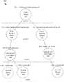
- FIG. 4Ashows an example diagram that includes a graph that includes multiple levels of master detail relationships, in accordance with some embodiments.
- the order product object 320may be related to adjustment line object 430 in a master detail relationship
- the order product object 325may be related to adjustment line object 435 in another master detail relationship.
- the adjustment line object 430may be related to the tax line object 440 in a master detail relationship
- the adjustment line object 435may be related to the tax line object 445 in another master detail relationship.
- the graph in diagram 400may include multiple RSFs in different master objects.
- the order object 305may include a RSF field “TotalAdjustmentTaxAmount” which may be configured to be based on a sum of the field “TotalLineAdjustmentTaxAmount” of the order product objects 320 and 325 .
- the value of the RSF field “TotalLineAdjustmentTaxAmount” of the order product object 320may be configured to be based on a sum of the field “TotalTaxAmount” of each related detail records in the adjustment line object 430 .
- the field “TotalTaxAmount” of the adjustment line object 430may be configured as a RSF, and its value may be based on a value of the field “TaxAmount” of a related detail record in the tax line object 440 .
- the tax line object 440may not include a RSF because it is not in a master detail relationship where it is a master object.
- a change to the data modelmay cause many recalculations to be performed.
- the tax line object 440may represent a county tax.
- a new tax line object 448shown in hyphenated lines
- the update of the RSF associated with the adjustment line object 430may require loading the order product object 320 and perform the calculation to update the RSF associated with the order product object 320 .
- the update of the RSF associated with the order product object 320may require loading the order object 305 and perform the calculation to update the RSF associated with the order object 305 .
- a server systemmay need to load a master object (e.g., adjustment line object 330 ) from the database and lock it to prevent concurrent modifications.
- the loading of an objectmay cause an increase in both execution time as well as database processing time, which is a shared resource across all tenants in a multi-tenant system. When there are tens of thousands of orders, the need to perform recalculations for all the RSFs can add significant load on the system.
- FIG. 4Bshows an example diagram that includes a directed graph that may be used to represent multiple RSFs in a data model, in accordance with some embodiments.
- the graph shown in diagram 450includes nodes or vertices connected by directional edges between two nodes.
- a graphmay be used to represent all the RSFs in a data model.
- the nodes of the graph shown in diagram 450may correspond to the RSFs in the first three levels of the graph in diagram 400 .
- Each node of the diagram 450may represent a value of a RSF of a corresponding object shown in FIG. 4A .
- a graph fieldmay be included in the object located at the root node of the data model.
- a graph fieldmay be included in the order object 305 in diagram 400 .
- each order record in the order object 305may include a graph field to represent all of the values of the RSFs associated with that order record.
- the data contained in a graph fieldmay be stored in a serialized format and is represented by a directed graph. Serialization may enable storing the graph as binary data that may be stored and transmitted. Deserialization may be performed to generate the graph structure from the serialized data.
- the graphmay be represented using a data structure that includes an array for the vertices.
- a directed edge between two nodesmay be represented as a pair of values in an order where a first value represents the “from” node and a second value represents the “to” node.
- a first valuerepresents the “from” node
- a second valuerepresents the “to” node.
- v1 and v4may be represented as ([v1, v2, v3, v4], [ ⁇ v1, v2 ⁇ , ⁇ v2, v3 ⁇ , ⁇ v1, v4 ⁇ ]).
- the pair of values( 455 , 465 ) may be used to represent the nodes connected by the edge 458 .
- An array for the verticesmay be used to represent the edges.
- the five nodes: 455 , 460 , 465 , 470 , and 475may be arranged in an array that may include five rows and five columns where a value of “1” may be used to indicate an edge exists between two nodes and a “0” may be used to indicate no edge exists between two nodes.
- the graphmay be represented using JGraphT, a Java library of graph theory data structures and algorithms of an open source software named JGraph.
- FIG. 4Cshows an example diagram that includes a directed graph with RSF values, in accordance with some embodiments.
- the nodes in diagram 480may correspond to the nodes in diagram 450 with each node in the diagram 480 showing a value for the RSF of the corresponding node in diagram 450 .
- the values of the RSFsmay represent tax amounts. For example, there may be an order that has two products, a t-shirt and a hat. The t-shirt is associated with the order product object 320 , while the hat is associated with the order product object 325 (shown in FIG. 4A ). The total tax amount to be paid for the t-shirt is 0.20 cent, and the total tax amount to be paid for the hat is 0.15 cent.
- the nodesmay be listed in the following order: 456 , 461 , 466 , 471 and 476 .
- the RSF valuesmay be represented by field names as follows:
- an applicationmay be configured to access the graph field of a record, deserialize the data included in the graph field to create a graph, determine a node in the graph where update needs to be made, and perform any necessary calculation to the RSFs affected by the update.
- a database administratormay need create the tax line object 448 (shown in hyphenated lines in FIG. 4A ) and update the data model to add the tax line object 448 .
- Tax line recordsmay be added to the tax line object 448 .
- the database administratormay also need to establish a master detail relationship between the adjustment line object 430 and the tax line object 448 .
- the database administratormay need to update the RSF field “TotalTaxAmount” of the adjustment line object 430 to indicate that its value is based on a sum of the two “TaxAmount” fields of the tax line objects 440 and 448 . Operations performed by the database administrator may be via an interface with a server computing system associated with the order object 305 .
- FIG. 5shows an example block diagram that includes an update application, in accordance with some embodiments.
- Update application 505may include graph module 510 , serialization module 515 , deserialization module 520 , and RSF update module 525 .
- adding the tax line object 448 to the data modelmay require the RSFs in the data model to be updated. Typically, this may require loading multiple objects and performing multiple calculations.
- the graph module 510may be configured to determine the values of the RSFs in a data model using a graph structure that is based on the data model.
- the serialization module 515may be configured to serialize the values of the RSFs and store the result in the graph field.
- the deserialization module 520may be configured to deserialize the data stored in the graph field to generate a graph.
- the RSF update module 525may be configured to perform updates on the RSFs in the graph when there is an update to the data model, or when there is an update to a value of a RSF. Together, the modules 510 - 525 may perform the operations for the update application 505 .
- the order recordsare updated to reflect a change to the data model when the tax line object 448 is added.
- the update application 505may be configured to be aware that the tax line object 448 is related to the adjustment line object 430 based on established master detail relationship. As such, the update application 505 may be aware of the node(s) in the graph that needs to be updated. After the data included in a graph field of an order record is deserialized, the update application 505 may traverse down the graph from the root node to find the affected node using the established master detail relationships. For example, the update application 505 may traverse a graph such as the graph shown in FIG.
- the update application 505may the traverse up the graph to find a next RSF that needs to be updated. For example, the update application 505 may update the value of the RSFs at nodes 460 and 455 .
- the traversing of the graphmay be based on the graph being a directed graph.
- RSF in a data modelmay not be updated by the update application 505 even when there is an update to another RSF in the data model.
- the update to the RSF “TotalTaxAmount” at node 470may not cause the RSF “TotalLineAdjustmentTaxAmount” at node 465 to be updated.
- FIG. 6shows an example diagram that includes a directed graph with updated RSF values, in accordance with some embodiments.
- the nodes 656 , 661 , 666 , 671 and 676 in diagram 600may correspond to the nodes 456 , 461 , 466 , 471 and 476 in diagram 480 with some nodes in the diagram 600 having updated values.
- the nodes 685 and 686are not part of the graph but are included to show the values used to calculate the value at the node 671 .
- the values of 0.10 cent and 0.20 cent at nodes 685 and 686represent the tax amounts from the tax line objects 448 and 450 (shown in FIG. 4A ).
- the value 0.30 cent at node 671represents an updated RSF value caused by the addition of the 0.10 cent at node 685 to the 0.20 cent at node 686 .
- the value 0.30 cent at node 661represents an updated RSF value caused by the update to the node 671 .
- the value 0.45 cent at node 656represents an updated RSF value caused by the update to the node 661 .
- the RSF values associated with an order recordmay be represented as follows: ⁇ 0.45, 0.30, 0.15, 0.30, 0.15 ⁇ .
- the above descriptionrefers to an update to a data model such as adding a new object (e.g., tax line object 448 ) to the data model
- the technique describedmay also be applicable when there is a change to a value of a RSF in the data model.
- FIG. 7Ais an example flow diagram of a process that may be used to serialize values of RSFs, in accordance with some embodiments.
- the process shown in diagram 700may be associated with a data model with multiple RSFs such as, for example, the data model described with FIGS. 4A-4C .
- the processmay be performed by an update application 505 described with FIG. 5 .
- the update application 505may determine the values of the RSFs associated with an object of a data model.
- the RSFsmay be associated with the objects included in the data model.
- the objectsmay be related with one another based on master detail relationships such as, for example, the master detail relationship described with FIG. 4A .
- the values of the RSFsmay be serialized using a graph representation that is based on the data model.
- the graph in FIG. 4Bis a graph representation of the values of the RSFs shown in FIG. 4A .
- the serialized datamay be stored in a graph field of the object.
- FIG. 7Bis an example flow diagram of a process that may be used to update RSFs of an object in a data model using graph representation, in accordance with some embodiments.
- the process shown in diagram 750may be performed by the update application 505 described with FIG. 5 to update multiple RSFs such as, for example, the RFSs described with FIGS. 4A-4C .
- the update application 505may retrieve data associated with RSFs of objects associated with a data model.
- the datamay have previously been stored in a graph field of an object in a serialized format.
- deserialization operationsmay be performed on the data to determine the values of the RSFs at nodes of a graph associated with the data model.
- the update applicationmay traverse down the graph from a root node to a node where an RSF update is to be calculated. The value of the RSF at the node may then be updated. The traversing of the graph may be based on established master detail relationships between objects of the data model.
- the update application 505may traverse up the graph toward the root node and perform any necessary updates of the RSFs at nodes that are affected by the updated RSF.
- the updatingmay involve the RSFs at different levels of the graph up to and including the root node.
- the values of the RSFs in the graphmay be serialized and stored in a graph field of the object.
- FIG. 8Ashows a system diagram 800 illustrating architectural components of an on-demand service environment, in accordance with some embodiments.
- a client machine located in the cloud 804may communicate with the on-demand service environment via one or more edge routers 808 and 812 .
- the edge routersmay communicate with one or more core switches 820 and 824 via firewall 816 .
- the core switchesmay communicate with a load balancer 828 , which may distribute server load over different pods, such as the pods 840 and 844 .
- the pods 840 and 844which may each include one or more servers and/or other computing resources, may perform data processing and other operations used to provide on-demand Services. Communication with the pods may be conducted via pod switches 832 and 836 .
- Components of the on-demand service environmentmay communicate with a database storage system 856 via a database firewall 848 and a database switch 852 .
- accessing an on-demand service environmentmay involve communications transmitted among a variety of different hardware and/or software components.
- the on-demand service environment 800is a simplified representation of an actual on-demand service environment. For example, while only one or two devices of each type are shown in FIGS. 8A and 8B , some embodiments of an on-demand service environment may include anywhere from one to many devices of each type. Also, the on-demand service environment need not include each device shown in FIGS. 8A and 8B , or may include additional devices not shown in FIGS. 8A and 8B .
- one or more of the devices in the on-demand service environment 800may be implemented on the same physical device or on different hardware. Some devices may be implemented using hardware or a combination of hardware and software.
- terms such as “data processing apparatus,” “machine,” “server” and “device” as used hereinare not limited to a single hardware device, but rather include any hardware and software configured to provide the described functionality.
- the cloud 804is intended to refer to a data network or plurality of data networks, often including the Internet.
- Client machines located in the cloud 804may communicate with the on-demand service environment to access services provided by the on-demand service environment. For example, client machines may access the on-demand service environment to retrieve, store, edit, and/or process information.
- the edge routers 808 and 812route packets between the cloud 804 and other components of the on-demand service environment 800 .
- the edge routers 808 and 812may employ the Border Gateway Protocol (BGP).
- BGPis the core routing protocol of the Internet.
- the edge routers 808 and 812may maintain a table of IP networks or ‘prefixes’ which designate network reachability among autonomous systems on the Internet.
- the firewall 816may protect the inner components of the on-demand service environment 800 from Internet traffic.
- the firewall 816may block, permit, or deny access to the inner components of the on-demand service environment 800 based upon a set of rules and other criteria.
- the firewall 816may act as one or more of a packet filter, an application gateway, a stateful filter, a proxy server, or any other type of firewall.
- the core switches 820 and 824are high-capacity switches that transfer packets within the on-demand service environment 800 .
- the core switches 820 and 824may be configured as network bridges that quickly route data between different components within the on-demand service environment.
- the use of two or more core switches 820 and 824may provide redundancy and/or reduced latency.
- the pods 840 and 844may perform the core data processing and service functions provided by the on-demand service environment.
- Each podmay include various types of hardware and/or software computing resources.
- An example of the pod architectureis discussed in greater detail with reference to FIG. 8B .
- communication between the pods 840 and 844may be conducted via the pod switches 832 and 836 .
- the pod switches 832 and 836may facilitate communication between the pods 840 and 844 and client machines located in the cloud 804 , for example via core switches 820 and 824 .
- the pod switches 832 and 836may facilitate communication between the pods 840 and 844 and the database storage 856 .
- the load balancer 828may distribute workload between the pods 840 and 844 . Balancing the on-demand service requests between the pods may assist in improving the use of resources, increasing throughput, reducing response times, and/or reducing overhead.
- the load balancer 828may include multilayer switches to analyze and forward traffic.
- access to the database storage 856may be guarded by a database firewall 848 .
- the database firewall 848may act as a computer application firewall operating at the database application layer of a protocol stack.
- the database firewall 848may protect the database storage 856 from application attacks such as structure query language (SQL) injection, database rootkits, and unauthorized information disclosure.
- SQLstructure query language
- the database firewall 848may include a host using one or more forms of reverse proxy services to proxy traffic before passing it to a gateway router.
- the database firewall 848may inspect the contents of database traffic and block certain content or database requests.
- the database firewall 848may work on the SQL application level atop the TCP/IP stack, managing applications' connection to the database or SQL management interfaces as well as intercepting and enforcing packets traveling to or from a database network or application interface.
- communication with the database storage system 856may be conducted via the database switch 852 .
- the multi-tenant database system 856may include more than one hardware and/or software components for handling database queries. Accordingly, the database switch 852 may direct database queries transmitted by other components of the on-demand service environment (e.g., the pods 840 and 844 ) to the correct components within the database storage system 856 .
- the database storage system 856is an on-demand database system shared by many different organizations.
- the on-demand database systemmay employ a multi-tenant approach, a virtualized approach, or any other type of database approach. An on-demand database system is discussed in greater detail with reference to FIGS. 9 and 10 .
- FIG. 8Bshows a system diagram illustrating the architecture of the pod 844 , in accordance with one embodiment.
- the pod 844may be used to render services to a user of the on-demand service environment 800 .
- each podmay include a variety of servers and/or other systems.
- the pod 844includes one or more content batch servers 864 , content search servers 868 , query servers 882 , Fileforce servers 886 , access control system (ACS) servers 880 , batch servers 884 , and app servers 888 .
- the pod 844includes database instances 890 , quick file systems (QFS) 892 , and indexers 894 . In one or more embodiments, some or all communication between the servers in the pod 844 may be transmitted via the switch 836 .
- QFSquick file systems
- the application servers 888may include a hardware and/or software framework dedicated to the execution of procedures (e.g., programs, routines, scripts) for supporting the construction of applications provided by the on-demand service environment 800 via the pod 844 . Some such procedures may include operations for providing the services described herein.
- the content batch servers 864may request internal to the pod. These requests may be long-running and/or not tied to a particular customer. For example, the content batch servers 864 may handle requests related to log mining, cleanup work, and maintenance tasks.
- the content search servers 868may provide query and indexer functions. For example, the functions provided by the content search servers 868 may allow users to search through content stored in the on-demand service environment.
- the Fileforce servers 886may manage requests information stored in the Fileforce storage 898 .
- the Fileforce storage 898may store information such as documents, images, and basic large objects (BLOBs). By managing requests for information using the Fileforce servers 886 , the image footprint on the database may be reduced.
- the query servers 882may be used to retrieve information from one or more file systems.
- the query system 872may receive requests for information from the app servers 888 and then transmit information queries to the NFS 896 located outside the pod.
- the pod 844may share a database instance 890 configured as a multi-tenant environment in which different organizations share access to the same database. Additionally, services rendered by the pod 844 may require various hardware and/or software resources.
- the ACS servers 880may control access to data, hardware resources, or software resources.
- the batch servers 884may process batch jobs, which are used to run tasks at specified times. Thus, the batch servers 884 may transmit instructions to other servers, such as the app servers 888 , to trigger the batch jobs.
- the QFS 892may be an open source file system available from Sun Microsystems® of Santa Clara, Calif. The QFS may serve as a rapid-access file system for storing and accessing information available within the pod 844 .
- the QFS 892may support some volume management capabilities, allowing many disks to be grouped together into a file system. File system metadata can be kept on a separate set of disks, which may be useful for streaming applications where long disk seeks cannot be tolerated.
- the QFS systemmay communicate with one or more content search servers 868 and/or indexers 894 to identify, retrieve, move, and/or update data stored in the network file systems 896 and/or other storage systems.
- one or more query servers 882may communicate with the NFS 896 to retrieve and/or update information stored outside of the pod 844 .
- the NFS 896may allow servers located in the pod 844 to access information to access files over a network in a manner similar to how local storage is accessed.
- queries from the query servers 882may be transmitted to the NFS 896 via the load balancer 820 , which may distribute resource requests over various resources available in the on-demand service environment.
- the NFS 896may also communicate with the QFS 892 to update the information stored on the NFS 896 and/or to provide information to the QFS 892 for use by servers located within the pod 844 .
- the podmay include one or more database instances 890 .
- the database instance 890may transmit information to the QFS 892 . When information is transmitted to the QFS, it may be available for use by servers within the pod 844 without requiring an additional database call.
- database informationmay be transmitted to the indexer 894 .
- Indexer 894may provide an index of information available in the database 890 and/or QFS 892 . The index information may be provided to Fileforce servers 886 and/or the QFS 892 .
- FIG. 9shows a block diagram of an environment 910 wherein an on-demand database service might be used, in accordance with some embodiments.
- Environment 910includes an on-demand database service 916 .
- User system 912may be any machine or system that is used by a user to access a database user system.
- any of user systems 912can be a handheld computing system, a mobile phone, a laptop computer, a work station, and/or a network of computing systems.
- user systems 912might interact via a network 914 with the on-demand database service 916 .
- An on-demand database servicesuch as system 916
- system 916is a database system that is made available to outside users that do not need to necessarily be concerned with building and/or maintaining the database system, but instead may be available for their use when the users need the database system (e.g., on the demand of the users).
- Some on-demand database servicesmay store information from one or more tenants stored into tables of a common database image to form a multi-tenant database system (MTS).
- MTSmulti-tenant database system
- “on-demand database service 916 ” and “system 916 ”will be used interchangeably herein.
- a database imagemay include one or more database objects.
- a relational database management system (RDBMS) or the equivalentmay execute storage and retrieval of information against the database object(s).
- RDBMSrelational database management system
- Application platform 918may be a framework that allows the applications of system 916 to run, such as the hardware and/or software, e.g., the operating system.
- on-demand database service 916may include an application platform 918 that enables creation, managing and executing one or more applications developed by the provider of the on-demand database service, users accessing the on-demand database service via user systems 912 , or third party application developers accessing the on-demand database service via user systems 912 .
- FIG. 9One arrangement for elements of system 916 is shown in FIG. 9 , including a network interface 920 , application platform 918 , tenant data storage 922 for tenant data 923 , system data storage 924 for system data 925 accessible to system 916 and possibly multiple tenants, program code 926 for implementing various functions of system 916 , and a process space 928 for executing MTS system processes and tenant-specific processes, such as running applications as part of an application hosting service. Additional processes that may execute on system 916 include database indexing processes.
- the users of user systems 912may differ in their respective capacities, and the capacity of a particular user system 912 might be entirely determined by permissions (permission levels) for the current user. For example, where a call center agent is using a particular user system 912 to interact with system 916 , the user system 912 has the capacities allotted to that call center agent. However, while an administrator is using that user system to interact with system 916 , that user system has the capacities allotted to that administrator. In systems with a hierarchical role model, users at one permission level may have access to applications, data, and database information accessible by a lower permission level user, but may not have access to certain applications, database information, and data accessible by a user at a higher permission level. Thus, different users may have different capabilities with regard to accessing and modifying application and database information, depending on a user's security or permission level.
- Network 914is any network or combination of networks of devices that communicate with one another.
- network 914can be any one or any combination of a LAN (local area network), WAN (wide area network), telephone network, wireless network, point-to-point network, star network, token ring network, hub network, or other appropriate configuration.
- LANlocal area network
- WANwide area network
- telephone networkwireless network
- wireless networkpoint-to-point network
- star networkstar network
- token ring networktoken ring network
- hub networkor other appropriate configuration.
- TCP/IPTransfer Control Protocol and Internet Protocol
- User systems 912might communicate with system 916 using TCP/IP and, at a higher network level, use other common Internet protocols to communicate, such as HTTP, FTP, AFS, WAP, etc.
- HTTPHyperText Transfer Protocol
- user system 912might include an HTTP client commonly referred to as a “browser” for sending and receiving HTTP messages to and from an HTTP server at system 916 .
- HTTP servermight be implemented as the sole network interface between system 916 and network 914 , but other techniques might be used as well or instead.
- the interface between system 916 and network 914includes load sharing functionality, such as round-robin HTTP request distributors to balance loads and distribute incoming HTTP requests evenly over a plurality of servers. At least as for the users that are accessing that server, each of the plurality of servers has access to the MTS' data; however, other alternative configurations may be used instead.
- system 916implements a web-based customer relationship management (CRM) system.
- system 916includes application servers configured to implement and execute CRM software applications as well as provide related data, code, forms, web pages and other information to and from user systems 912 and to store to, and retrieve from, a database system related data, objects, and Webpage content.
- CRMcustomer relationship management
- system 916includes application servers configured to implement and execute CRM software applications as well as provide related data, code, forms, web pages and other information to and from user systems 912 and to store to, and retrieve from, a database system related data, objects, and Webpage content.
- tenant datatypically is arranged so that data of one tenant is kept logically separate from that of other tenants so that one tenant does not have access to another tenant's data, unless such data is expressly shared.
- system 916implements applications other than, or in addition to, a CRM application.
- system 916may provide tenant access to multiple hosted (standard and custom) applications.
- User (or third party developer) applicationswhich may or may not include CRM, may be supported by the application platform 918 , which manages creation, storage of the applications into one or more database objects and executing of the applications in a virtual machine in the process space of the system 916 .
- Each user system 912could include a desktop personal computer, workstation, laptop, PDA, cell phone, or any wireless access protocol (WAP) enabled device or any other computing system capable of interfacing directly or indirectly to the Internet or other network connection.
- User system 912typically runs an HTTP client, e.g., a browsing program, such as Microsoft's Internet Explorer® browser, Mozilla's Firefox® browser, Opera's browser, or a WAP-enabled browser in the case of a cell phone, PDA or other wireless device, or the like, allowing a user (e.g., subscriber of the multi-tenant database system) of user system 912 to access, process and view information, pages and applications available to it from system 916 over network 914 .
- HTTP cliente.g., a browsing program, such as Microsoft's Internet Explorer® browser, Mozilla's Firefox® browser, Opera's browser, or a WAP-enabled browser in the case of a cell phone, PDA or other wireless device, or the like.
- Each user system 912also typically includes one or more user interface devices, such as a keyboard, a mouse, trackball, touch pad, touch screen, pen or the like, for interacting with a graphical user interface (GUI) provided by the browser on a display (e.g., a monitor screen, LCD display, etc.) in conjunction with pages, forms, applications and other information provided by system 916 or other systems or servers.
- GUIgraphical user interface
- the user interface devicecan be used to access data and applications hosted by system 916 , and to perform searches on stored data, and otherwise allow a user to interact with various GUI pages that may be presented to a user.
- embodimentsare suitable for use with the Internet, which refers to a specific global internetwork of networks. However, it should be understood that other networks can be used instead of the Internet, such as an intranet, an extranet, a virtual private network (VPN), a non-TCP/IP based network, any LAN or WAN or the like.
- VPNvirtual private network
- each user system 912 and all of its componentsare operator configurable using applications, such as a browser, including computer code run using a central processing unit such as an Intel Pentium® processor or the like.
- system 916 (and additional instances of an MTS, where more than one is present) and all of their componentsmight be operator configurable using application(s) including computer code to run using a central processing unit such as processor system 917 , which may include an Intel Pentium® processor or the like, and/or multiple processor units.
- a computer program product implementationincludes a machine-readable storage medium (media) having instructions stored thereon/in which can be used to program a computer to perform any of the processes of the embodiments described herein.
- Computer code for operating and configuring system 916 to intercommunicate and to process web pages, applications and other data and media content as described hereinare preferably downloaded and stored on a hard disk, but the entire program code, or portions thereof, may also be stored in any other volatile or non-volatile memory medium or device, such as a ROM or RAM, or provided on any media capable of storing program code, such as any type of rotating media including floppy disks, optical discs, digital versatile disk (DVD), compact disk (CD), microdrive, and magneto-optical disks, and magnetic or optical cards, nanosystems (including molecular memory ICs), or any type of media or device suitable for storing instructions and/or data.
- program codemay be transmitted and downloaded from a software source over a transmission medium, e.g., over the Internet, or from another server, or transmitted over any other conventional network connection (e.g., extranet, VPN, LAN, etc.) using any communication medium and protocols (e.g., TCP/IP, HTTP, HTTPS, Ethernet, etc.).
- a transmission mediume.g., over the Internet
- any other conventional network connectione.g., extranet, VPN, LAN, etc.
- any communication medium and protocolse.g., TCP/IP, HTTP, HTTPS, Ethernet, etc.
- computer code for implementing embodimentscan be implemented in any programming language that can be executed on a client system and/or server or server system such as, for example, C, C++, HTML, any other markup language, JavaTM, JavaScript®, ActiveX®, any other scripting language, such as VBScript, and many other programming languages as are well known may be used.
- JavaTMis a trademark of Sun Microsystems®, Inc.
- each system 916is configured to provide web pages, forms, applications, data and media content to user (client) systems 912 to support the access by user systems 912 as tenants of system 916 .
- system 916provides security mechanisms to keep each tenant's data separate unless the data is shared.
- MTSmulti-tenant system
- theymay be located in close proximity to one another (e.g., in a server farm located in a single building or campus), or they may be distributed at locations remote from one another (e.g., one or more servers located in city A and one or more servers located in city B).
- each MTScould include logically and/or physically connected servers distributed locally or across one or more geographic locations.
- serveris meant to include a computing system, including processing hardware and process space(s), and an associated storage system and database application (e.g., OODBMS or RDBMS) as is well known in the art.
- server systemand “server” are often used interchangeably herein.
- database object described hereincan be implemented as single databases, a distributed database, a collection of distributed databases, a database with redundant online or offline backups or other redundancies, etc., and might include a distributed database or storage network and associated processing intelligence.
- FIG. 10also shows a block diagram of environment 910 further illustrating system 916 and various interconnections, in accordance with some embodiments.
- FIG. 10shows that user system 912 may include processor system 912 A, memory system 912 B, input system 912 C, and output system 912 D.
- FIG. 10shows network 914 and system 916 .
- system 916may include tenant data storage 922 , tenant data 923 , system data storage 924 , system data 925 , User Interface (UI) 1030 , Application Program Interface (API) 1032 , PL/SOQL 1034 , save routines 1036 , application setup mechanism 1038 , applications servers 10001 - 1000 N, system process space 1002 , tenant process spaces 1004 , tenant management process space 1010 , tenant storage area 1012 , user storage 1014 , and application metadata 1016 .
- environment 910may not have the same elements as those listed above and/or may have other elements instead of, or in addition to, those listed above.
- processor system 912 Amay be any combination of processors.
- Memory system 912 Bmay be any combination of one or more memory devices, short term, and/or long term memory.
- Input system 912 Cmay be any combination of input devices, such as keyboards, mice, trackballs, scanners, cameras, and/or interfaces to networks.
- Output system 912 Dmay be any combination of output devices, such as monitors, printers, and/or interfaces to networks.
- system 916may include a network interface 920 (of FIG.
- Each application server 1000may be configured to tenant data storage 922 and the tenant data 923 therein, and system data storage 924 and the system data 925 therein to serve requests of user systems 912 .
- the tenant data 923might be divided into individual tenant storage areas 1012 , which can be either a physical arrangement and/or a logical arrangement of data.
- user storage 1014 and application metadata 1016might be similarly allocated for each user.
- a copy of a user's most recently used (MRU) itemsmight be stored to user storage 1014 .
- a copy of MRU items for an entire organization that is a tenantmight be stored to tenant storage area 1012 .
- a UI 1030provides a user interface and an API 1032 provides an application programmer interface to system 916 resident processes to users and/or developers at user systems 912 .
- the tenant data and the system datamay be stored in various databases, such as OracleTM databases.
- Application platform 918includes an application setup mechanism 1038 that supports application developers' creation and management of applications, which may be saved as metadata into tenant data storage 922 by save routines 1036 for execution by subscribers as tenant process spaces 1004 managed by tenant management process 1010 for example. Invocations to such applications may be coded using PL/SOQL 34 that provides a programming language style interface extension to API 1032 .
- PL/SOQL 34provides a programming language style interface extension to API 1032 .
- a detailed description of some PL/SOQL language embodimentsis discussed in commonly assigned U.S. Pat. No. 7,730,478, titled METHOD AND SYSTEM FOR ALLOWING ACCESS TO DEVELOPED APPLICATIONS VIA A MULTI-TENANT ON-DEMAND DATABASE SERVICE, by Craig Weissman, filed Sep. 21, 4007, which is hereby incorporated by reference in its entirety and for all purposes.
- Invocations to applicationsmay be detected by system processes, which manage retrieving application metadata 1016 for the subscriber making
- Each application server 1000may be communicably coupled to database systems, e.g., having access to system data 925 and tenant data 923 , via a different network connection.
- one application server 10001might be coupled via the network 914 (e.g., the Internet)
- another application server 1000 N ⁇ 1might be coupled via a direct network link
- another application server 1000 Nmight be coupled by yet a different network connection.
- Transfer Control Protocol and Internet ProtocolTCP/IP are typical protocols for communicating between application servers 1000 and the database system. However, other transport protocols may be used to optimize the system depending on the network interconnect used.
- each application server 1000is configured to handle requests for any user associated with any organization that is a tenant. Because it is desirable to be able to add and remove application servers from the server pool at any time for any reason, there is preferably no server affinity for a user and/or organization to a specific application server 1000 .
- an interface system implementing a load balancing functione.g., an F5 Big-IP load balancer
- the load balanceruses a least connections algorithm to route user requests to the application servers 1000 .
- Other examples of load balancing algorithmssuch as round robin and observed response time, also can be used.
- system 916is multi-tenant, wherein system 916 handles storage of, and access to, different objects, data and applications across disparate users and organizations.
- one tenantmight be a company that employs a sales force where each call center agent uses system 916 to manage their sales process.
- a usermight maintain contact data, leads data, customer follow-up data, performance data, goals and progress data, etc., all applicable to that user's personal sales process (e.g., in tenant data storage 922 ).
- tenant data storage 922e.g., in tenant data storage 922 .
- the usercan manage his or her sales efforts and cycles from any of many different user systems. For example, if a call center agent is visiting a customer and the customer has Internet access in their lobby, the call center agent can obtain critical updates as to that customer while waiting for the customer to arrive in the lobby.
- user systems 912(which may be client machines/systems) communicate with application servers 1000 to request and update system-level and tenant-level data from system 916 that may require sending one or more queries to tenant data storage 922 and/or system data storage 924 .
- System 916e.g., an application server 1000 in system 916
- System data storage 924may generate query plans to access the requested data from the database.
- Each databasecan generally be viewed as a collection of objects, such as a set of logical tables, containing data fitted into predefined categories.
- a “table”is one representation of a data object, and may be used herein to simplify the conceptual description of objects and custom objects according to some embodiments. It should be understood that “table” and “object” may be used interchangeably herein.
- Each tablegenerally contains one or more data categories logically arranged as columns or fields in a viewable schema. Each row or record of a table contains an instance of data for each category defined by the fields.
- a CRM databasemay include a table that describes a customer with fields for basic contact information such as name, address, phone number, fax number, etc.
- Another tablemight describe a purchase order, including fields for information such as customer, product, sale price, date, etc.
- standard entity tablesmight be provided for use by all tenants.
- such standard entitiesmight include tables for account, contact, lead, and opportunity data, each containing pre-defined fields. It should be understood that the word “entity” may also be used interchangeably herein with “object” and “table”.
- tenantsmay be allowed to create and store custom objects, or they may be allowed to customize standard entities or objects, for example by creating custom fields for standard objects, including custom index fields.
- all custom entity data rowsare stored in a single multi-tenant physical table, which may contain multiple logical tables per organization.
- multiple “tables” for a single customermay actually be stored in one large table and/or in the same table as the data of other customers.
- machine-program productthat include program instructions, state information, etc., for performing various operations described herein.
- program instructionsinclude both machine code, such as produced by a compiler, and files containing higher-level code that may be executed by the computer using an interpreter.
- machine-program productinclude, but are not limited to, magnetic media such as hard disks, floppy disks, and magnetic tape; optical media such as CD-ROM disks; magneto-optical media; and hardware devices that are specially configured to store and perform program instructions, such as read-only memory devices (“ROM”) and random access memory (“RAM”).
- ROMread-only memory devices
- RAMrandom access memory
- While one or more embodiments and techniquesare described with reference to an implementation in which a service cloud console is implemented in a system having an application server providing a front end for an on-demand database service capable of supporting multiple tenants, the one or more embodiments and techniques are not limited to multi-tenant databases nor deployment on application servers. Embodiments may be practiced using other database architectures, i.e., ORACLE®, DB2® by IBM and the like without departing from the scope of the embodiments claimed.
- any of the above embodimentsmay be used alone or together with one another in any combination.
- various embodimentsmay have been motivated by various deficiencies with the prior art, which may be discussed or alluded to in one or more places in the specification, the embodiments do not necessarily address any of these deficiencies.
- different embodimentsmay address different deficiencies that may be discussed in the specification.
- Some embodimentsmay only partially address some deficiencies or just one deficiency that may be discussed in the specification, and some embodiments may not address any of these deficiencies.
Landscapes
- Engineering & Computer Science (AREA)
- Theoretical Computer Science (AREA)
- Databases & Information Systems (AREA)
- Data Mining & Analysis (AREA)
- Physics & Mathematics (AREA)
- General Engineering & Computer Science (AREA)
- General Physics & Mathematics (AREA)
- Software Systems (AREA)
- Information Retrieval, Db Structures And Fs Structures Therefor (AREA)
- Stored Programmes (AREA)
Abstract
Description
- {Order.TotalAdjustmentTaxAmount, OrderProduct1.TotalLineAdjustmentTaxAmount OrderProduct2.TotalLineAdjustmentTaxAmount AdjustmentLine1.TotalTaxAmount AdjustmentLine2.TotalTaxAmount},
or represented by values as follows: - {0.35, 0.20, 0.15, 0.20, 0.15}.
- {Order.TotalAdjustmentTaxAmount, OrderProduct1.TotalLineAdjustmentTaxAmount OrderProduct2.TotalLineAdjustmentTaxAmount AdjustmentLine1.TotalTaxAmount AdjustmentLine2.TotalTaxAmount},
Claims (21)
Priority Applications (1)
| Application Number | Priority Date | Filing Date | Title |
|---|---|---|---|
| US16/741,248US11442989B2 (en) | 2020-01-13 | 2020-01-13 | Scalable roll-up summary field calculation using graphs |
Applications Claiming Priority (1)
| Application Number | Priority Date | Filing Date | Title |
|---|---|---|---|
| US16/741,248US11442989B2 (en) | 2020-01-13 | 2020-01-13 | Scalable roll-up summary field calculation using graphs |
Publications (2)
| Publication Number | Publication Date |
|---|---|
| US20210216591A1 US20210216591A1 (en) | 2021-07-15 |
| US11442989B2true US11442989B2 (en) | 2022-09-13 |
Family
ID=76760581
Family Applications (1)
| Application Number | Title | Priority Date | Filing Date |
|---|---|---|---|
| US16/741,248Active2040-07-19US11442989B2 (en) | 2020-01-13 | 2020-01-13 | Scalable roll-up summary field calculation using graphs |
Country Status (1)
| Country | Link |
|---|---|
| US (1) | US11442989B2 (en) |
Cited By (4)
| Publication number | Priority date | Publication date | Assignee | Title |
|---|---|---|---|---|
| US12106131B2 (en) | 2022-11-23 | 2024-10-01 | Salesforce, Inc. | Metadata driven guided rules editor |
| US12235849B2 (en) | 2022-11-23 | 2025-02-25 | Salesforce, Inc. | Multi-context stateful rule execution |
| US12395488B2 (en) | 2022-04-13 | 2025-08-19 | Wiz, Inc. | Techniques for analyzing external exposure in cloud environments |
| US12443720B2 (en) | 2022-08-10 | 2025-10-14 | Wiz, Inc. | Techniques for detecting applications paths utilizing exposure analysis |
Families Citing this family (1)
| Publication number | Priority date | Publication date | Assignee | Title |
|---|---|---|---|---|
| US11397736B2 (en) | 2020-01-27 | 2022-07-26 | Salesforce, Inc. | Large scale data ingestion |
Citations (123)
| Publication number | Priority date | Publication date | Assignee | Title |
|---|---|---|---|---|
| US5577188A (en) | 1994-05-31 | 1996-11-19 | Future Labs, Inc. | Method to provide for virtual screen overlay |
| US5608872A (en) | 1993-03-19 | 1997-03-04 | Ncr Corporation | System for allowing all remote computers to perform annotation on an image and replicating the annotated image on the respective displays of other comuters |
| US5649104A (en) | 1993-03-19 | 1997-07-15 | Ncr Corporation | System for allowing user of any computer to draw image over that generated by the host computer and replicating the drawn image to other computers |
| US5715450A (en) | 1995-09-27 | 1998-02-03 | Siebel Systems, Inc. | Method of selecting and presenting data from a database using a query language to a user of a computer system |
| US5821937A (en) | 1996-02-23 | 1998-10-13 | Netsuite Development, L.P. | Computer method for updating a network design |
| US5831610A (en) | 1996-02-23 | 1998-11-03 | Netsuite Development L.P. | Designing networks |
| US5873096A (en) | 1997-10-08 | 1999-02-16 | Siebel Systems, Inc. | Method of maintaining a network of partially replicated database system |
| US5918159A (en) | 1997-08-04 | 1999-06-29 | Fomukong; Mundi | Location reporting satellite paging system with optional blocking of location reporting |
| US5963953A (en) | 1998-03-30 | 1999-10-05 | Siebel Systems, Inc. | Method, and system for product configuration |
| US6092083A (en) | 1997-02-26 | 2000-07-18 | Siebel Systems, Inc. | Database management system which synchronizes an enterprise server and a workgroup user client using a docking agent |
| US6161149A (en) | 1998-03-13 | 2000-12-12 | Groupserve, Inc. | Centrifugal communication and collaboration method |
| US6169534B1 (en) | 1997-06-26 | 2001-01-02 | Upshot.Com | Graphical user interface for customer information management |
| US6178425B1 (en) | 1997-02-26 | 2001-01-23 | Siebel Systems, Inc. | Method of determining the visibility to a remote database client of a plurality of database transactions using simplified visibility rules |
| US6216135B1 (en) | 1997-02-26 | 2001-04-10 | Siebel Systems, Inc. | Method of determining visibility to a remote database client of a plurality of database transactions having variable visibility strengths |
| US6233617B1 (en) | 1997-02-26 | 2001-05-15 | Siebel Systems, Inc. | Determining the visibility to a remote database client |
| US6266669B1 (en) | 1997-02-28 | 2001-07-24 | Siebel Systems, Inc. | Partially replicated distributed database with multiple levels of remote clients |
| US6295530B1 (en) | 1995-05-15 | 2001-09-25 | Andrew M. Ritchie | Internet service of differently formatted viewable data signals including commands for browser execution |
| US20010044791A1 (en) | 2000-04-14 | 2001-11-22 | Richter James Neal | Automated adaptive classification system for bayesian knowledge networks |
| US6324693B1 (en) | 1997-03-12 | 2001-11-27 | Siebel Systems, Inc. | Method of synchronizing independently distributed software and database schema |
| US6324568B1 (en) | 1999-11-30 | 2001-11-27 | Siebel Systems, Inc. | Method and system for distributing objects over a network |
| US6336137B1 (en) | 2000-03-31 | 2002-01-01 | Siebel Systems, Inc. | Web client-server system and method for incompatible page markup and presentation languages |
| USD454139S1 (en) | 2001-02-20 | 2002-03-05 | Rightnow Technologies | Display screen for a computer |
| US6367077B1 (en) | 1997-02-27 | 2002-04-02 | Siebel Systems, Inc. | Method of upgrading a software application in the presence of user modifications |
| US6393605B1 (en) | 1998-11-18 | 2002-05-21 | Siebel Systems, Inc. | Apparatus and system for efficient delivery and deployment of an application |
| US20020072951A1 (en) | 1999-03-03 | 2002-06-13 | Michael Lee | Marketing support database management method, system and program product |
| US20020082892A1 (en) | 1998-08-27 | 2002-06-27 | Keith Raffel | Method and apparatus for network-based sales force management |
| US6434550B1 (en) | 2000-04-14 | 2002-08-13 | Rightnow Technologies, Inc. | Temporal updates of relevancy rating of retrieved information in an information search system |
| US6446089B1 (en) | 1997-02-26 | 2002-09-03 | Siebel Systems, Inc. | Method of using a cache to determine the visibility to a remote database client of a plurality of database transactions |
| US20020140731A1 (en) | 2001-03-28 | 2002-10-03 | Pavitra Subramaniam | Engine to present a user interface based on a logical structure, such as one for a customer relationship management system, across a web site |
| US20020143997A1 (en) | 2001-03-28 | 2002-10-03 | Xiaofei Huang | Method and system for direct server synchronization with a computing device |
| US20020162090A1 (en) | 2001-04-30 | 2002-10-31 | Parnell Karen P. | Polylingual simultaneous shipping of software |
| US20020165742A1 (en) | 2000-03-31 | 2002-11-07 | Mark Robins | Feature centric release manager method and system |
| US20030004971A1 (en) | 2001-06-29 | 2003-01-02 | Gong Wen G. | Automatic generation of data models and accompanying user interfaces |
| US20030018705A1 (en) | 2001-03-31 | 2003-01-23 | Mingte Chen | Media-independent communication server |
| US20030018830A1 (en) | 2001-02-06 | 2003-01-23 | Mingte Chen | Adaptive communication application programming interface |
| US6535909B1 (en) | 1999-11-18 | 2003-03-18 | Contigo Software, Inc. | System and method for record and playback of collaborative Web browsing session |
| US20030066031A1 (en) | 2001-09-28 | 2003-04-03 | Siebel Systems, Inc. | Method and system for supporting user navigation in a browser environment |
| US20030066032A1 (en) | 2001-09-28 | 2003-04-03 | Siebel Systems,Inc. | System and method for facilitating user interaction in a browser environment |
| US20030069936A1 (en) | 2001-10-09 | 2003-04-10 | Warner Douglas K. | Method for routing electronic correspondence based on the level and type of emotion contained therein |
| US20030070005A1 (en) | 2001-09-29 | 2003-04-10 | Anil Mukundan | Method, apparatus, and system for implementing view caching in a framework to support web-based applications |
| US20030070004A1 (en) | 2001-09-29 | 2003-04-10 | Anil Mukundan | Method, apparatus, and system for implementing a framework to support a web-based application |
| US20030070000A1 (en) | 2001-09-29 | 2003-04-10 | John Coker | Computing system and method to implicitly commit unsaved data for a World Wide Web application |
| US20030074418A1 (en) | 2001-09-29 | 2003-04-17 | John Coker | Method, apparatus and system for a mobile web client |
| US6553563B2 (en) | 1998-11-30 | 2003-04-22 | Siebel Systems, Inc. | Development tool, method, and system for client server applications |
| US6560461B1 (en) | 1997-08-04 | 2003-05-06 | Mundi Fomukong | Authorized location reporting paging system |
| US6574635B2 (en) | 1999-03-03 | 2003-06-03 | Siebel Systems, Inc. | Application instantiation based upon attributes and values stored in a meta data repository, including tiering of application layers objects and components |
| US6577726B1 (en) | 2000-03-31 | 2003-06-10 | Siebel Systems, Inc. | Computer telephony integration hotelling method and system |
| US6601087B1 (en) | 1998-11-18 | 2003-07-29 | Webex Communications, Inc. | Instant document sharing |
| US6604117B2 (en) | 1996-03-19 | 2003-08-05 | Siebel Systems, Inc. | Method of maintaining a network of partially replicated database system |
| US20030151633A1 (en) | 2002-02-13 | 2003-08-14 | David George | Method and system for enabling connectivity to a data system |
| US20030159136A1 (en) | 2001-09-28 | 2003-08-21 | Huang Xiao Fei | Method and system for server synchronization with a computing device |
| US6621834B1 (en) | 1999-11-05 | 2003-09-16 | Raindance Communications, Inc. | System and method for voice transmission over network protocols |
| US20030189600A1 (en) | 2002-03-29 | 2003-10-09 | Prasad Gune | Defining an approval process for requests for approval |
| US20030204427A1 (en) | 2002-03-29 | 2003-10-30 | Prasad Gune | User interface for processing requests for approval |
| US20030206192A1 (en) | 2001-03-31 | 2003-11-06 | Mingte Chen | Asynchronous message push to web browser |
| US6654032B1 (en) | 1999-12-23 | 2003-11-25 | Webex Communications, Inc. | Instant sharing of documents on a remote server |
| US6665655B1 (en) | 2000-04-14 | 2003-12-16 | Rightnow Technologies, Inc. | Implicit rating of retrieved information in an information search system |
| US6665648B2 (en) | 1998-11-30 | 2003-12-16 | Siebel Systems, Inc. | State models for monitoring process |
| US20040001092A1 (en) | 2002-06-27 | 2004-01-01 | Rothwein Thomas M. | Prototyping graphical user interfaces |
| US20040015981A1 (en) | 2002-06-27 | 2004-01-22 | Coker John L. | Efficient high-interactivity user interface for client-server applications |
| US20040027388A1 (en) | 2002-06-27 | 2004-02-12 | Eric Berg | Method and apparatus to facilitate development of a customer-specific business process model |
| US6711565B1 (en) | 2001-06-18 | 2004-03-23 | Siebel Systems, Inc. | Method, apparatus, and system for previewing search results |
| US6724399B1 (en) | 2001-09-28 | 2004-04-20 | Siebel Systems, Inc. | Methods and apparatus for enabling keyboard accelerators in applications implemented via a browser |
| US6728702B1 (en) | 2001-06-18 | 2004-04-27 | Siebel Systems, Inc. | System and method to implement an integrated search center supporting a full-text search and query on a database |
| US6728960B1 (en) | 1998-11-18 | 2004-04-27 | Siebel Systems, Inc. | Techniques for managing multiple threads in a browser environment |
| US6732111B2 (en) | 1998-03-03 | 2004-05-04 | Siebel Systems, Inc. | Method, apparatus, system, and program product for attaching files and other objects to a partially replicated database |
| US6732095B1 (en) | 2001-04-13 | 2004-05-04 | Siebel Systems, Inc. | Method and apparatus for mapping between XML and relational representations |
| US6732100B1 (en) | 2000-03-31 | 2004-05-04 | Siebel Systems, Inc. | Database access method and system for user role defined access |
| US20040128001A1 (en) | 2002-08-28 | 2004-07-01 | Levin Issac Stephen | Method and apparatus for an integrated process modeller |
| US6763501B1 (en) | 2000-06-09 | 2004-07-13 | Webex Communications, Inc. | Remote document serving |
| US6763351B1 (en) | 2001-06-18 | 2004-07-13 | Siebel Systems, Inc. | Method, apparatus, and system for attaching search results |
| US6768904B2 (en) | 2000-10-11 | 2004-07-27 | Lg Electronics Inc. | Data communication method using mobile terminal |
| US6772229B1 (en) | 2000-11-13 | 2004-08-03 | Groupserve, Inc. | Centrifugal communication and collaboration method |
| US6782383B2 (en) | 2001-06-18 | 2004-08-24 | Siebel Systems, Inc. | System and method to implement a persistent and dismissible search center frame |
| US20040186860A1 (en) | 2003-03-21 | 2004-09-23 | Wen-Hsin Lee | Method and architecture for providing data-change alerts to external applications via a push service |
| US20040193510A1 (en) | 2003-03-25 | 2004-09-30 | Catahan Nardo B. | Modeling of order data |
| US20040199489A1 (en) | 2003-03-24 | 2004-10-07 | Barnes-Leon Maria Theresa | Custom common object |
| US20040199536A1 (en) | 2003-03-24 | 2004-10-07 | Barnes Leon Maria Theresa | Product common object |
| US6804330B1 (en) | 2002-01-04 | 2004-10-12 | Siebel Systems, Inc. | Method and system for accessing CRM data via voice |
| US6826745B2 (en) | 1998-11-30 | 2004-11-30 | Siebel Systems, Inc. | System and method for smart scripting call centers and configuration thereof |
| US6826582B1 (en) | 2001-09-28 | 2004-11-30 | Emc Corporation | Method and system for using file systems for content management |
| US6829655B1 (en) | 2001-03-28 | 2004-12-07 | Siebel Systems, Inc. | Method and system for server synchronization with a computing device via a companion device |
| US20040249854A1 (en) | 2003-03-24 | 2004-12-09 | Barnes-Leon Maria Theresa | Common common object |
| US20040260534A1 (en) | 2003-06-19 | 2004-12-23 | Pak Wai H. | Intelligent data search |
| US20040260659A1 (en) | 2003-06-23 | 2004-12-23 | Len Chan | Function space reservation system |
| US20040268299A1 (en) | 2003-06-30 | 2004-12-30 | Shu Lei | Application user interface template with free-form layout |
| US6842748B1 (en) | 2000-04-14 | 2005-01-11 | Rightnow Technologies, Inc. | Usage based strength between related information in an information retrieval system |
| US6850895B2 (en) | 1998-11-30 | 2005-02-01 | Siebel Systems, Inc. | Assignment manager |
| US6850949B2 (en) | 2002-06-03 | 2005-02-01 | Right Now Technologies, Inc. | System and method for generating a dynamic interface via a communications network |
| US20050050555A1 (en) | 2003-08-28 | 2005-03-03 | Exley Richard Mark | Universal application network architecture |
| US7062502B1 (en) | 2001-12-28 | 2006-06-13 | Kesler John N | Automated generation of dynamic data entry user interface for relational database management systems |
| US7340411B2 (en) | 1998-02-26 | 2008-03-04 | Cook Rachael L | System and method for generating, capturing, and managing customer lead information over a computer network |
| US7356482B2 (en) | 1998-12-18 | 2008-04-08 | Alternative Systems, Inc. | Integrated change management unit |
| US20090063415A1 (en) | 2007-08-31 | 2009-03-05 | Business Objects, S.A. | Apparatus and method for dynamically selecting componentized executable instructions at run time |
| US20090100342A1 (en) | 2007-10-12 | 2009-04-16 | Gabriel Jakobson | Method and system for presenting address and mapping information |
| US20090177744A1 (en) | 2008-01-04 | 2009-07-09 | Yahoo! Inc. | Identifying and employing social network relationships |
| US7620655B2 (en) | 2003-05-07 | 2009-11-17 | Enecto Ab | Method, device and computer program product for identifying visitors of websites |
| US7698160B2 (en) | 1999-05-07 | 2010-04-13 | Virtualagility, Inc | System for performing collaborative tasks |
| US7730478B2 (en) | 2006-10-04 | 2010-06-01 | Salesforce.Com, Inc. | Method and system for allowing access to developed applications via a multi-tenant on-demand database service |
| US7779039B2 (en) | 2004-04-02 | 2010-08-17 | Salesforce.Com, Inc. | Custom entities and fields in a multi-tenant database system |
| US7779475B2 (en) | 2006-07-31 | 2010-08-17 | Petnote Llc | Software-based method for gaining privacy by affecting the screen of a computing device |
| US7814124B1 (en)* | 2001-06-27 | 2010-10-12 | Microsoft Corporation | Architecture and method for serialization and deserialization of objects |
| US7851004B2 (en) | 2001-07-19 | 2010-12-14 | San-Ei Gen F.F.I., Inc. | Taste-improving composition and application of the same |
| US8010663B2 (en) | 2008-11-21 | 2011-08-30 | The Invention Science Fund I, Llc | Correlating data indicating subjective user states associated with multiple users with data indicating objective occurrences |
| US8014943B2 (en) | 2008-05-08 | 2011-09-06 | Gabriel Jakobson | Method and system for displaying social networking navigation information |
| US20110238705A1 (en)* | 2010-03-25 | 2011-09-29 | Salesforce.Com, Inc. | System, method and computer program product for extending a master-detail relationship |
| US8032297B2 (en) | 2008-05-08 | 2011-10-04 | Gabriel Jakobson | Method and system for displaying navigation information on an electronic map |
| US8082301B2 (en) | 2006-11-10 | 2011-12-20 | Virtual Agility, Inc. | System for supporting collaborative activity |
| US8095413B1 (en) | 1999-05-07 | 2012-01-10 | VirtualAgility, Inc. | Processing management information |
| US8209308B2 (en) | 2006-05-01 | 2012-06-26 | Rueben Steven L | Method for presentation of revisions of an electronic document |
| US20120233137A1 (en) | 2006-05-01 | 2012-09-13 | Gabriel Jakobson | Presentation of document history in a web browsing application |
| US8490025B2 (en) | 2008-02-01 | 2013-07-16 | Gabriel Jakobson | Displaying content associated with electronic mapping systems |
| US8504945B2 (en) | 2008-02-01 | 2013-08-06 | Gabriel Jakobson | Method and system for associating content with map zoom function |
| US8510664B2 (en) | 2008-09-06 | 2013-08-13 | Steven L. Rueben | Method and system for displaying email thread information |
| US20130218949A1 (en) | 2012-02-17 | 2013-08-22 | Gabriel Jakobson | Collaborative web browsing system integrated with social networks |
| US20130218948A1 (en) | 2012-02-17 | 2013-08-22 | Gabriel Jakobson | Variable speed collaborative web browsing system |
| US20130218966A1 (en) | 2012-02-17 | 2013-08-22 | Gabriel Jakobson | Collaborative web browsing system having document object model element interaction detection |
| US8566301B2 (en) | 2006-05-01 | 2013-10-22 | Steven L. Rueben | Document revisions in a collaborative computing environment |
| US8646103B2 (en) | 2008-06-30 | 2014-02-04 | Gabriel Jakobson | Method and system for securing online identities |
| US20140359537A1 (en) | 2008-02-01 | 2014-12-04 | Gabriel Jackobson | Online advertising associated with electronic mapping systems |
| US20150007050A1 (en) | 2013-07-01 | 2015-01-01 | Gabriel Jakobson | Method and system for processing and displaying email thread information |
| US20150095162A1 (en) | 2013-09-27 | 2015-04-02 | Gabriel Jakobson | Method and systems for online advertising to users using fictitious user idetities |
| US20150172563A1 (en) | 2013-12-18 | 2015-06-18 | Gabriel Jakobson | Incorporating advertising content into a digital video |
- 2020
- 2020-01-13USUS16/741,248patent/US11442989B2/enactiveActive
Patent Citations (142)
| Publication number | Priority date | Publication date | Assignee | Title |
|---|---|---|---|---|
| US5608872A (en) | 1993-03-19 | 1997-03-04 | Ncr Corporation | System for allowing all remote computers to perform annotation on an image and replicating the annotated image on the respective displays of other comuters |
| US5649104A (en) | 1993-03-19 | 1997-07-15 | Ncr Corporation | System for allowing user of any computer to draw image over that generated by the host computer and replicating the drawn image to other computers |
| US5761419A (en) | 1993-03-19 | 1998-06-02 | Ncr Corporation | Remote collaboration system including first program means translating user inputs into annotations and running on all computers while second program means runs on one computer |
| US5819038A (en) | 1993-03-19 | 1998-10-06 | Ncr Corporation | Collaboration system for producing copies of image generated by first program on first computer on other computers and annotating the image by second program |
| US5577188A (en) | 1994-05-31 | 1996-11-19 | Future Labs, Inc. | Method to provide for virtual screen overlay |
| US6826565B2 (en) | 1995-05-15 | 2004-11-30 | Ablaise Limited | Method and apparatus for serving files to browsing clients |
| US6295530B1 (en) | 1995-05-15 | 2001-09-25 | Andrew M. Ritchie | Internet service of differently formatted viewable data signals including commands for browser execution |
| US5715450A (en) | 1995-09-27 | 1998-02-03 | Siebel Systems, Inc. | Method of selecting and presenting data from a database using a query language to a user of a computer system |
| US5821937A (en) | 1996-02-23 | 1998-10-13 | Netsuite Development, L.P. | Computer method for updating a network design |
| US5831610A (en) | 1996-02-23 | 1998-11-03 | Netsuite Development L.P. | Designing networks |
| US6189011B1 (en) | 1996-03-19 | 2001-02-13 | Siebel Systems, Inc. | Method of maintaining a network of partially replicated database system |
| US6604117B2 (en) | 1996-03-19 | 2003-08-05 | Siebel Systems, Inc. | Method of maintaining a network of partially replicated database system |
| US6216135B1 (en) | 1997-02-26 | 2001-04-10 | Siebel Systems, Inc. | Method of determining visibility to a remote database client of a plurality of database transactions having variable visibility strengths |
| US6684438B2 (en) | 1997-02-26 | 2004-02-03 | Siebel Systems, Inc. | Method of using cache to determine the visibility to a remote database client of a plurality of database transactions |
| US6178425B1 (en) | 1997-02-26 | 2001-01-23 | Siebel Systems, Inc. | Method of determining the visibility to a remote database client of a plurality of database transactions using simplified visibility rules |
| US6092083A (en) | 1997-02-26 | 2000-07-18 | Siebel Systems, Inc. | Database management system which synchronizes an enterprise server and a workgroup user client using a docking agent |
| US6233617B1 (en) | 1997-02-26 | 2001-05-15 | Siebel Systems, Inc. | Determining the visibility to a remote database client |
| US6446089B1 (en) | 1997-02-26 | 2002-09-03 | Siebel Systems, Inc. | Method of using a cache to determine the visibility to a remote database client of a plurality of database transactions |
| US20020129352A1 (en) | 1997-02-27 | 2002-09-12 | Brodersen Robert A. | Method and apparatus for upgrading a software application in the presence of user modifications |
| US6367077B1 (en) | 1997-02-27 | 2002-04-02 | Siebel Systems, Inc. | Method of upgrading a software application in the presence of user modifications |
| US6754681B2 (en) | 1997-02-28 | 2004-06-22 | Siebel Systems, Inc. | Partially replicated distributed database with multiple levels of remote clients |
| US6405220B1 (en) | 1997-02-28 | 2002-06-11 | Siebel Systems, Inc. | Partially replicated distributed database with multiple levels of remote clients |
| US6266669B1 (en) | 1997-02-28 | 2001-07-24 | Siebel Systems, Inc. | Partially replicated distributed database with multiple levels of remote clients |
| US6324693B1 (en) | 1997-03-12 | 2001-11-27 | Siebel Systems, Inc. | Method of synchronizing independently distributed software and database schema |
| US6169534B1 (en) | 1997-06-26 | 2001-01-02 | Upshot.Com | Graphical user interface for customer information management |
| US5918159A (en) | 1997-08-04 | 1999-06-29 | Fomukong; Mundi | Location reporting satellite paging system with optional blocking of location reporting |
| US6560461B1 (en) | 1997-08-04 | 2003-05-06 | Mundi Fomukong | Authorized location reporting paging system |
| US5873096A (en) | 1997-10-08 | 1999-02-16 | Siebel Systems, Inc. | Method of maintaining a network of partially replicated database system |
| US7340411B2 (en) | 1998-02-26 | 2008-03-04 | Cook Rachael L | System and method for generating, capturing, and managing customer lead information over a computer network |
| US6732111B2 (en) | 1998-03-03 | 2004-05-04 | Siebel Systems, Inc. | Method, apparatus, system, and program product for attaching files and other objects to a partially replicated database |
| US6161149A (en) | 1998-03-13 | 2000-12-12 | Groupserve, Inc. | Centrifugal communication and collaboration method |
| US8015495B2 (en) | 1998-03-13 | 2011-09-06 | Groupserve It Trust Llc | Centrifugal communication and collaboration method |
| US5963953A (en) | 1998-03-30 | 1999-10-05 | Siebel Systems, Inc. | Method, and system for product configuration |
| US20020082892A1 (en) | 1998-08-27 | 2002-06-27 | Keith Raffel | Method and apparatus for network-based sales force management |
| US6601087B1 (en) | 1998-11-18 | 2003-07-29 | Webex Communications, Inc. | Instant document sharing |
| US6393605B1 (en) | 1998-11-18 | 2002-05-21 | Siebel Systems, Inc. | Apparatus and system for efficient delivery and deployment of an application |
| US6728960B1 (en) | 1998-11-18 | 2004-04-27 | Siebel Systems, Inc. | Techniques for managing multiple threads in a browser environment |
| US6549908B1 (en) | 1998-11-18 | 2003-04-15 | Siebel Systems, Inc. | Methods and apparatus for interpreting user selections in the context of a relation distributed as a set of orthogonalized sub-relations |
| US20050091098A1 (en) | 1998-11-30 | 2005-04-28 | Siebel Systems, Inc. | Assignment manager |
| US6665648B2 (en) | 1998-11-30 | 2003-12-16 | Siebel Systems, Inc. | State models for monitoring process |
| US6826745B2 (en) | 1998-11-30 | 2004-11-30 | Siebel Systems, Inc. | System and method for smart scripting call centers and configuration thereof |
| US6553563B2 (en) | 1998-11-30 | 2003-04-22 | Siebel Systems, Inc. | Development tool, method, and system for client server applications |
| US6850895B2 (en) | 1998-11-30 | 2005-02-01 | Siebel Systems, Inc. | Assignment manager |
| US8484111B2 (en) | 1998-12-18 | 2013-07-09 | Applications In Internet Time, Llc | Integrated change management unit |
| US7356482B2 (en) | 1998-12-18 | 2008-04-08 | Alternative Systems, Inc. | Integrated change management unit |
| US20020072951A1 (en) | 1999-03-03 | 2002-06-13 | Michael Lee | Marketing support database management method, system and program product |
| US6574635B2 (en) | 1999-03-03 | 2003-06-03 | Siebel Systems, Inc. | Application instantiation based upon attributes and values stored in a meta data repository, including tiering of application layers objects and components |
| US20030120675A1 (en) | 1999-03-03 | 2003-06-26 | Siebel Systems, Inc. | Application instantiation based upon attributes and values stored in a meta data repository, including tiering of application layers, objects, and components |
| US7698160B2 (en) | 1999-05-07 | 2010-04-13 | Virtualagility, Inc | System for performing collaborative tasks |
| US8095594B2 (en) | 1999-05-07 | 2012-01-10 | VirtualAgility, Inc. | System for performing collaborative tasks |
| US8275836B2 (en) | 1999-05-07 | 2012-09-25 | Virtualagility Inc. | System and method for supporting collaborative activity |
| US8095413B1 (en) | 1999-05-07 | 2012-01-10 | VirtualAgility, Inc. | Processing management information |
| US6621834B1 (en) | 1999-11-05 | 2003-09-16 | Raindance Communications, Inc. | System and method for voice transmission over network protocols |
| US6535909B1 (en) | 1999-11-18 | 2003-03-18 | Contigo Software, Inc. | System and method for record and playback of collaborative Web browsing session |
| US20030187921A1 (en) | 1999-11-30 | 2003-10-02 | Siebel Systems, Inc. | Method and system for distributing objects over a network |
| US6324568B1 (en) | 1999-11-30 | 2001-11-27 | Siebel Systems, Inc. | Method and system for distributing objects over a network |
| US6604128B2 (en) | 1999-11-30 | 2003-08-05 | Siebel Systems, Inc. | Method and system for distributing objects over a network |
| US6654032B1 (en) | 1999-12-23 | 2003-11-25 | Webex Communications, Inc. | Instant sharing of documents on a remote server |
| US6577726B1 (en) | 2000-03-31 | 2003-06-10 | Siebel Systems, Inc. | Computer telephony integration hotelling method and system |
| US6609150B2 (en) | 2000-03-31 | 2003-08-19 | Siebel Systems, Inc. | Web client-server system and method for incompatible page markup and presentation languages |
| US6336137B1 (en) | 2000-03-31 | 2002-01-01 | Siebel Systems, Inc. | Web client-server system and method for incompatible page markup and presentation languages |
| US6732100B1 (en) | 2000-03-31 | 2004-05-04 | Siebel Systems, Inc. | Database access method and system for user role defined access |
| US20020165742A1 (en) | 2000-03-31 | 2002-11-07 | Mark Robins | Feature centric release manager method and system |
| US6434550B1 (en) | 2000-04-14 | 2002-08-13 | Rightnow Technologies, Inc. | Temporal updates of relevancy rating of retrieved information in an information search system |
| US6665655B1 (en) | 2000-04-14 | 2003-12-16 | Rightnow Technologies, Inc. | Implicit rating of retrieved information in an information search system |
| US6842748B1 (en) | 2000-04-14 | 2005-01-11 | Rightnow Technologies, Inc. | Usage based strength between related information in an information retrieval system |
| US20010044791A1 (en) | 2000-04-14 | 2001-11-22 | Richter James Neal | Automated adaptive classification system for bayesian knowledge networks |
| US6763501B1 (en) | 2000-06-09 | 2004-07-13 | Webex Communications, Inc. | Remote document serving |
| US6768904B2 (en) | 2000-10-11 | 2004-07-27 | Lg Electronics Inc. | Data communication method using mobile terminal |
| US6772229B1 (en) | 2000-11-13 | 2004-08-03 | Groupserve, Inc. | Centrifugal communication and collaboration method |
| US20030018830A1 (en) | 2001-02-06 | 2003-01-23 | Mingte Chen | Adaptive communication application programming interface |
| USD454139S1 (en) | 2001-02-20 | 2002-03-05 | Rightnow Technologies | Display screen for a computer |
| US20020143997A1 (en) | 2001-03-28 | 2002-10-03 | Xiaofei Huang | Method and system for direct server synchronization with a computing device |
| US6829655B1 (en) | 2001-03-28 | 2004-12-07 | Siebel Systems, Inc. | Method and system for server synchronization with a computing device via a companion device |
| US20020140731A1 (en) | 2001-03-28 | 2002-10-03 | Pavitra Subramaniam | Engine to present a user interface based on a logical structure, such as one for a customer relationship management system, across a web site |
| US20030018705A1 (en) | 2001-03-31 | 2003-01-23 | Mingte Chen | Media-independent communication server |
| US20030206192A1 (en) | 2001-03-31 | 2003-11-06 | Mingte Chen | Asynchronous message push to web browser |
| US6732095B1 (en) | 2001-04-13 | 2004-05-04 | Siebel Systems, Inc. | Method and apparatus for mapping between XML and relational representations |
| US20020162090A1 (en) | 2001-04-30 | 2002-10-31 | Parnell Karen P. | Polylingual simultaneous shipping of software |
| US6763351B1 (en) | 2001-06-18 | 2004-07-13 | Siebel Systems, Inc. | Method, apparatus, and system for attaching search results |
| US6711565B1 (en) | 2001-06-18 | 2004-03-23 | Siebel Systems, Inc. | Method, apparatus, and system for previewing search results |
| US6728702B1 (en) | 2001-06-18 | 2004-04-27 | Siebel Systems, Inc. | System and method to implement an integrated search center supporting a full-text search and query on a database |
| US6782383B2 (en) | 2001-06-18 | 2004-08-24 | Siebel Systems, Inc. | System and method to implement a persistent and dismissible search center frame |
| US7814124B1 (en)* | 2001-06-27 | 2010-10-12 | Microsoft Corporation | Architecture and method for serialization and deserialization of objects |
| US20030004971A1 (en) | 2001-06-29 | 2003-01-02 | Gong Wen G. | Automatic generation of data models and accompanying user interfaces |
| US7851004B2 (en) | 2001-07-19 | 2010-12-14 | San-Ei Gen F.F.I., Inc. | Taste-improving composition and application of the same |
| US20030066031A1 (en) | 2001-09-28 | 2003-04-03 | Siebel Systems, Inc. | Method and system for supporting user navigation in a browser environment |
| US20030066032A1 (en) | 2001-09-28 | 2003-04-03 | Siebel Systems,Inc. | System and method for facilitating user interaction in a browser environment |
| US6724399B1 (en) | 2001-09-28 | 2004-04-20 | Siebel Systems, Inc. | Methods and apparatus for enabling keyboard accelerators in applications implemented via a browser |
| US20030159136A1 (en) | 2001-09-28 | 2003-08-21 | Huang Xiao Fei | Method and system for server synchronization with a computing device |
| US6826582B1 (en) | 2001-09-28 | 2004-11-30 | Emc Corporation | Method and system for using file systems for content management |
| US20030070005A1 (en) | 2001-09-29 | 2003-04-10 | Anil Mukundan | Method, apparatus, and system for implementing view caching in a framework to support web-based applications |
| US20030070004A1 (en) | 2001-09-29 | 2003-04-10 | Anil Mukundan | Method, apparatus, and system for implementing a framework to support a web-based application |
| US20030074418A1 (en) | 2001-09-29 | 2003-04-17 | John Coker | Method, apparatus and system for a mobile web client |
| US20030070000A1 (en) | 2001-09-29 | 2003-04-10 | John Coker | Computing system and method to implicitly commit unsaved data for a World Wide Web application |
| US20030069936A1 (en) | 2001-10-09 | 2003-04-10 | Warner Douglas K. | Method for routing electronic correspondence based on the level and type of emotion contained therein |
| US7401094B1 (en) | 2001-12-28 | 2008-07-15 | Kesler John N | Automated generation of dynamic data entry user interface for relational database management systems |
| US7062502B1 (en) | 2001-12-28 | 2006-06-13 | Kesler John N | Automated generation of dynamic data entry user interface for relational database management systems |
| US6804330B1 (en) | 2002-01-04 | 2004-10-12 | Siebel Systems, Inc. | Method and system for accessing CRM data via voice |
| US20030151633A1 (en) | 2002-02-13 | 2003-08-14 | David George | Method and system for enabling connectivity to a data system |
| US20030189600A1 (en) | 2002-03-29 | 2003-10-09 | Prasad Gune | Defining an approval process for requests for approval |
| US20030204427A1 (en) | 2002-03-29 | 2003-10-30 | Prasad Gune | User interface for processing requests for approval |
| US6850949B2 (en) | 2002-06-03 | 2005-02-01 | Right Now Technologies, Inc. | System and method for generating a dynamic interface via a communications network |
| US20040027388A1 (en) | 2002-06-27 | 2004-02-12 | Eric Berg | Method and apparatus to facilitate development of a customer-specific business process model |
| US20040001092A1 (en) | 2002-06-27 | 2004-01-01 | Rothwein Thomas M. | Prototyping graphical user interfaces |
| US20040015981A1 (en) | 2002-06-27 | 2004-01-22 | Coker John L. | Efficient high-interactivity user interface for client-server applications |
| US20040128001A1 (en) | 2002-08-28 | 2004-07-01 | Levin Issac Stephen | Method and apparatus for an integrated process modeller |
| US20040186860A1 (en) | 2003-03-21 | 2004-09-23 | Wen-Hsin Lee | Method and architecture for providing data-change alerts to external applications via a push service |
| US20040249854A1 (en) | 2003-03-24 | 2004-12-09 | Barnes-Leon Maria Theresa | Common common object |
| US20040199489A1 (en) | 2003-03-24 | 2004-10-07 | Barnes-Leon Maria Theresa | Custom common object |
| US20040199536A1 (en) | 2003-03-24 | 2004-10-07 | Barnes Leon Maria Theresa | Product common object |
| US20040193510A1 (en) | 2003-03-25 | 2004-09-30 | Catahan Nardo B. | Modeling of order data |
| US7620655B2 (en) | 2003-05-07 | 2009-11-17 | Enecto Ab | Method, device and computer program product for identifying visitors of websites |
| US20040260534A1 (en) | 2003-06-19 | 2004-12-23 | Pak Wai H. | Intelligent data search |
| US20040260659A1 (en) | 2003-06-23 | 2004-12-23 | Len Chan | Function space reservation system |
| US20040268299A1 (en) | 2003-06-30 | 2004-12-30 | Shu Lei | Application user interface template with free-form layout |
| US20050050555A1 (en) | 2003-08-28 | 2005-03-03 | Exley Richard Mark | Universal application network architecture |
| US7779039B2 (en) | 2004-04-02 | 2010-08-17 | Salesforce.Com, Inc. | Custom entities and fields in a multi-tenant database system |
| US8566301B2 (en) | 2006-05-01 | 2013-10-22 | Steven L. Rueben | Document revisions in a collaborative computing environment |
| US20120233137A1 (en) | 2006-05-01 | 2012-09-13 | Gabriel Jakobson | Presentation of document history in a web browsing application |
| US8209308B2 (en) | 2006-05-01 | 2012-06-26 | Rueben Steven L | Method for presentation of revisions of an electronic document |
| US7779475B2 (en) | 2006-07-31 | 2010-08-17 | Petnote Llc | Software-based method for gaining privacy by affecting the screen of a computing device |
| US7730478B2 (en) | 2006-10-04 | 2010-06-01 | Salesforce.Com, Inc. | Method and system for allowing access to developed applications via a multi-tenant on-demand database service |
| US8082301B2 (en) | 2006-11-10 | 2011-12-20 | Virtual Agility, Inc. | System for supporting collaborative activity |
| US20090063415A1 (en) | 2007-08-31 | 2009-03-05 | Business Objects, S.A. | Apparatus and method for dynamically selecting componentized executable instructions at run time |
| US20090100342A1 (en) | 2007-10-12 | 2009-04-16 | Gabriel Jakobson | Method and system for presenting address and mapping information |
| US20090177744A1 (en) | 2008-01-04 | 2009-07-09 | Yahoo! Inc. | Identifying and employing social network relationships |
| US8490025B2 (en) | 2008-02-01 | 2013-07-16 | Gabriel Jakobson | Displaying content associated with electronic mapping systems |
| US20140359537A1 (en) | 2008-02-01 | 2014-12-04 | Gabriel Jackobson | Online advertising associated with electronic mapping systems |
| US8504945B2 (en) | 2008-02-01 | 2013-08-06 | Gabriel Jakobson | Method and system for associating content with map zoom function |
| US8032297B2 (en) | 2008-05-08 | 2011-10-04 | Gabriel Jakobson | Method and system for displaying navigation information on an electronic map |
| US8014943B2 (en) | 2008-05-08 | 2011-09-06 | Gabriel Jakobson | Method and system for displaying social networking navigation information |
| US8646103B2 (en) | 2008-06-30 | 2014-02-04 | Gabriel Jakobson | Method and system for securing online identities |
| US8510664B2 (en) | 2008-09-06 | 2013-08-13 | Steven L. Rueben | Method and system for displaying email thread information |
| US8010663B2 (en) | 2008-11-21 | 2011-08-30 | The Invention Science Fund I, Llc | Correlating data indicating subjective user states associated with multiple users with data indicating objective occurrences |
| US20110238705A1 (en)* | 2010-03-25 | 2011-09-29 | Salesforce.Com, Inc. | System, method and computer program product for extending a master-detail relationship |
| US20130218949A1 (en) | 2012-02-17 | 2013-08-22 | Gabriel Jakobson | Collaborative web browsing system integrated with social networks |
| US20130218948A1 (en) | 2012-02-17 | 2013-08-22 | Gabriel Jakobson | Variable speed collaborative web browsing system |
| US20130218966A1 (en) | 2012-02-17 | 2013-08-22 | Gabriel Jakobson | Collaborative web browsing system having document object model element interaction detection |
| US20150007050A1 (en) | 2013-07-01 | 2015-01-01 | Gabriel Jakobson | Method and system for processing and displaying email thread information |
| US20150095162A1 (en) | 2013-09-27 | 2015-04-02 | Gabriel Jakobson | Method and systems for online advertising to users using fictitious user idetities |
| US20150172563A1 (en) | 2013-12-18 | 2015-06-18 | Gabriel Jakobson | Incorporating advertising content into a digital video |
Cited By (7)
| Publication number | Priority date | Publication date | Assignee | Title |
|---|---|---|---|---|
| US12395488B2 (en) | 2022-04-13 | 2025-08-19 | Wiz, Inc. | Techniques for analyzing external exposure in cloud environments |
| US12443720B2 (en) | 2022-08-10 | 2025-10-14 | Wiz, Inc. | Techniques for detecting applications paths utilizing exposure analysis |
| US12443722B2 (en) | 2022-11-14 | 2025-10-14 | Wiz, Inc. | Detecting vulnerabilities in configuration code of a cloud environment utilizing infrastructure as code |
| US12106131B2 (en) | 2022-11-23 | 2024-10-01 | Salesforce, Inc. | Metadata driven guided rules editor |
| US12118373B2 (en) | 2022-11-23 | 2024-10-15 | Salesforce, Inc. | Metadata driven guided rules editor |
| US12164945B2 (en) | 2022-11-23 | 2024-12-10 | Salesforce, Inc. | Metadata driven guided rules editor |
| US12235849B2 (en) | 2022-11-23 | 2025-02-25 | Salesforce, Inc. | Multi-context stateful rule execution |
Also Published As
| Publication number | Publication date |
|---|---|
| US20210216591A1 (en) | 2021-07-15 |
Similar Documents
| Publication | Publication Date | Title |
|---|---|---|
| US9830398B2 (en) | System and method for associating dynamic objects with database records | |
| US10949395B2 (en) | Cross objects de-duplication | |
| US10558626B2 (en) | Merging and unmerging objects using graphical representation | |
| US10152497B2 (en) | Bulk deduplication detection | |
| US10733613B2 (en) | Methods and systems for performing data assessment | |
| US10282175B2 (en) | Methods and systems for performing a partial build | |
| US20180189330A1 (en) | Database schema for efficient data assessment | |
| US10956450B2 (en) | Dense subset clustering | |
| US11614967B2 (en) | Distributed scheduling in a virtual machine environment | |
| US11442989B2 (en) | Scalable roll-up summary field calculation using graphs | |
| US20170293629A1 (en) | Merging multiple groups of records containing duplicates | |
| US10521406B2 (en) | Merging along object hierarchies | |
| US12223305B2 (en) | Methods and systems for deployment of services | |
| US20180210713A1 (en) | Methods and systems for using cross repositories | |
| US10482086B2 (en) | Identifying similar database queries | |
| US10803465B2 (en) | Enabling hierarchical structure representation of entities | |
| US11416484B2 (en) | Performance optimization of hybrid sharing model queries | |
| US20210342037A1 (en) | Palette management in user interface | |
| US11675800B2 (en) | Version control and execution on a mobile device | |
| US10637861B2 (en) | Validating state change requests | |
| US10210276B2 (en) | Managing information displayed in web pages | |
| US11003427B2 (en) | Interface for generating and testing formulas using a formula language | |
| US11010143B2 (en) | Executing formulas written using formula language | |
| US11120015B2 (en) | Importing data using a mobile computing device | |
| US10290127B2 (en) | Responsive line display |
Legal Events
| Date | Code | Title | Description |
|---|---|---|---|
| AS | Assignment | Owner name:SALESFORCE.COM, INC., CALIFORNIA Free format text:ASSIGNMENT OF ASSIGNORS INTEREST;ASSIGNORS:DVINOV, DANIL;VAISHNAV, PARTH;REEL/FRAME:051498/0935 Effective date:20200113 | |
| FEPP | Fee payment procedure | Free format text:ENTITY STATUS SET TO UNDISCOUNTED (ORIGINAL EVENT CODE: BIG.); ENTITY STATUS OF PATENT OWNER: LARGE ENTITY | |
| STPP | Information on status: patent application and granting procedure in general | Free format text:DOCKETED NEW CASE - READY FOR EXAMINATION | |
| STPP | Information on status: patent application and granting procedure in general | Free format text:NON FINAL ACTION MAILED | |
| STPP | Information on status: patent application and granting procedure in general | Free format text:RESPONSE TO NON-FINAL OFFICE ACTION ENTERED AND FORWARDED TO EXAMINER | |
| STPP | Information on status: patent application and granting procedure in general | Free format text:FINAL REJECTION MAILED | |
| STPP | Information on status: patent application and granting procedure in general | Free format text:DOCKETED NEW CASE - READY FOR EXAMINATION | |
| STPP | Information on status: patent application and granting procedure in general | Free format text:NOTICE OF ALLOWANCE MAILED -- APPLICATION RECEIVED IN OFFICE OF PUBLICATIONS | |
| STPP | Information on status: patent application and granting procedure in general | Free format text:PUBLICATIONS -- ISSUE FEE PAYMENT VERIFIED | |
| STCF | Information on status: patent grant | Free format text:PATENTED CASE | |
| AS | Assignment | Owner name:SALESFORCE, INC., CALIFORNIA Free format text:CHANGE OF NAME;ASSIGNOR:SALESFORCE.COM, INC.;REEL/FRAME:064975/0956 Effective date:20220325 |