US11440650B2 - Independent control for upper and lower rotor of a rotary wing aircraft - Google Patents
Independent control for upper and lower rotor of a rotary wing aircraftDownload PDFInfo
- Publication number
- US11440650B2 US11440650B2US15/504,525US201515504525AUS11440650B2US 11440650 B2US11440650 B2US 11440650B2US 201515504525 AUS201515504525 AUS 201515504525AUS 11440650 B2US11440650 B2US 11440650B2
- Authority
- US
- United States
- Prior art keywords
- rotor assembly
- control
- aircraft
- lower rotor
- upper rotor
- Prior art date
- Legal status (The legal status is an assumption and is not a legal conclusion. Google has not performed a legal analysis and makes no representation as to the accuracy of the status listed.)
- Active, expires
Links
Images


Classifications
- B—PERFORMING OPERATIONS; TRANSPORTING
- B64—AIRCRAFT; AVIATION; COSMONAUTICS
- B64C—AEROPLANES; HELICOPTERS
- B64C7/00—Structures or fairings not otherwise provided for
- B—PERFORMING OPERATIONS; TRANSPORTING
- B64—AIRCRAFT; AVIATION; COSMONAUTICS
- B64C—AEROPLANES; HELICOPTERS
- B64C1/00—Fuselages; Constructional features common to fuselages, wings, stabilising surfaces or the like
- B64C1/0009—Aerodynamic aspects
- B—PERFORMING OPERATIONS; TRANSPORTING
- B64—AIRCRAFT; AVIATION; COSMONAUTICS
- B64C—AEROPLANES; HELICOPTERS
- B64C13/00—Control systems or transmitting systems for actuating flying-control surfaces, lift-increasing flaps, air brakes, or spoilers
- B64C13/02—Initiating means
- B64C13/04—Initiating means actuated personally
- B—PERFORMING OPERATIONS; TRANSPORTING
- B64—AIRCRAFT; AVIATION; COSMONAUTICS
- B64C—AEROPLANES; HELICOPTERS
- B64C13/00—Control systems or transmitting systems for actuating flying-control surfaces, lift-increasing flaps, air brakes, or spoilers
- B64C13/02—Initiating means
- B64C13/16—Initiating means actuated automatically, e.g. responsive to gust detectors
- B64C13/18—Initiating means actuated automatically, e.g. responsive to gust detectors using automatic pilot
- B—PERFORMING OPERATIONS; TRANSPORTING
- B64—AIRCRAFT; AVIATION; COSMONAUTICS
- B64C—AEROPLANES; HELICOPTERS
- B64C13/00—Control systems or transmitting systems for actuating flying-control surfaces, lift-increasing flaps, air brakes, or spoilers
- B64C13/24—Transmitting means
- B64C13/38—Transmitting means with power amplification
- B64C13/50—Transmitting means with power amplification using electrical energy
- B64C13/503—Fly-by-Wire
- B—PERFORMING OPERATIONS; TRANSPORTING
- B64—AIRCRAFT; AVIATION; COSMONAUTICS
- B64C—AEROPLANES; HELICOPTERS
- B64C19/00—Aircraft control not otherwise provided for
- B—PERFORMING OPERATIONS; TRANSPORTING
- B64—AIRCRAFT; AVIATION; COSMONAUTICS
- B64C—AEROPLANES; HELICOPTERS
- B64C27/00—Rotorcraft; Rotors peculiar thereto
- B64C27/001—Vibration damping devices
- B—PERFORMING OPERATIONS; TRANSPORTING
- B64—AIRCRAFT; AVIATION; COSMONAUTICS
- B64C—AEROPLANES; HELICOPTERS
- B64C27/00—Rotorcraft; Rotors peculiar thereto
- B64C27/006—Safety devices
- B—PERFORMING OPERATIONS; TRANSPORTING
- B64—AIRCRAFT; AVIATION; COSMONAUTICS
- B64C—AEROPLANES; HELICOPTERS
- B64C27/00—Rotorcraft; Rotors peculiar thereto
- B64C27/008—Rotors tracking or balancing devices
- B—PERFORMING OPERATIONS; TRANSPORTING
- B64—AIRCRAFT; AVIATION; COSMONAUTICS
- B64C—AEROPLANES; HELICOPTERS
- B64C27/00—Rotorcraft; Rotors peculiar thereto
- B64C27/04—Helicopters
- B64C27/08—Helicopters with two or more rotors
- B64C27/10—Helicopters with two or more rotors arranged coaxially
- B—PERFORMING OPERATIONS; TRANSPORTING
- B64—AIRCRAFT; AVIATION; COSMONAUTICS
- B64C—AEROPLANES; HELICOPTERS
- B64C27/00—Rotorcraft; Rotors peculiar thereto
- B64C27/04—Helicopters
- B64C27/12—Rotor drives
- B—PERFORMING OPERATIONS; TRANSPORTING
- B64—AIRCRAFT; AVIATION; COSMONAUTICS
- B64C—AEROPLANES; HELICOPTERS
- B64C27/00—Rotorcraft; Rotors peculiar thereto
- B64C27/04—Helicopters
- B64C27/12—Rotor drives
- B64C27/14—Direct drive between power plant and rotor hub
- B—PERFORMING OPERATIONS; TRANSPORTING
- B64—AIRCRAFT; AVIATION; COSMONAUTICS
- B64C—AEROPLANES; HELICOPTERS
- B64C27/00—Rotorcraft; Rotors peculiar thereto
- B64C27/04—Helicopters
- B64C27/12—Rotor drives
- B64C27/16—Drive of rotors by means, e.g. propellers, mounted on rotor blades
- B—PERFORMING OPERATIONS; TRANSPORTING
- B64—AIRCRAFT; AVIATION; COSMONAUTICS
- B64C—AEROPLANES; HELICOPTERS
- B64C27/00—Rotorcraft; Rotors peculiar thereto
- B64C27/32—Rotors
- B—PERFORMING OPERATIONS; TRANSPORTING
- B64—AIRCRAFT; AVIATION; COSMONAUTICS
- B64C—AEROPLANES; HELICOPTERS
- B64C27/00—Rotorcraft; Rotors peculiar thereto
- B64C27/32—Rotors
- B64C27/322—Blade travel limiting devices, e.g. droop stops
- B—PERFORMING OPERATIONS; TRANSPORTING
- B64—AIRCRAFT; AVIATION; COSMONAUTICS
- B64C—AEROPLANES; HELICOPTERS
- B64C27/00—Rotorcraft; Rotors peculiar thereto
- B64C27/32—Rotors
- B64C27/33—Rotors having flexing arms
- B—PERFORMING OPERATIONS; TRANSPORTING
- B64—AIRCRAFT; AVIATION; COSMONAUTICS
- B64C—AEROPLANES; HELICOPTERS
- B64C27/00—Rotorcraft; Rotors peculiar thereto
- B64C27/32—Rotors
- B64C27/46—Blades
- B64C27/467—Aerodynamic features
- B—PERFORMING OPERATIONS; TRANSPORTING
- B64—AIRCRAFT; AVIATION; COSMONAUTICS
- B64C—AEROPLANES; HELICOPTERS
- B64C27/00—Rotorcraft; Rotors peculiar thereto
- B64C27/32—Rotors
- B64C27/46—Blades
- B64C27/473—Constructional features
- B—PERFORMING OPERATIONS; TRANSPORTING
- B64—AIRCRAFT; AVIATION; COSMONAUTICS
- B64C—AEROPLANES; HELICOPTERS
- B64C27/00—Rotorcraft; Rotors peculiar thereto
- B64C27/32—Rotors
- B64C27/46—Blades
- B64C27/473—Constructional features
- B64C27/48—Root attachment to rotor head
- B—PERFORMING OPERATIONS; TRANSPORTING
- B64—AIRCRAFT; AVIATION; COSMONAUTICS
- B64C—AEROPLANES; HELICOPTERS
- B64C27/00—Rotorcraft; Rotors peculiar thereto
- B64C27/51—Damping of blade movements
- B—PERFORMING OPERATIONS; TRANSPORTING
- B64—AIRCRAFT; AVIATION; COSMONAUTICS
- B64C—AEROPLANES; HELICOPTERS
- B64C27/00—Rotorcraft; Rotors peculiar thereto
- B64C27/52—Tilting of rotor bodily relative to fuselage
- B—PERFORMING OPERATIONS; TRANSPORTING
- B64—AIRCRAFT; AVIATION; COSMONAUTICS
- B64C—AEROPLANES; HELICOPTERS
- B64C27/00—Rotorcraft; Rotors peculiar thereto
- B64C27/54—Mechanisms for controlling blade adjustment or movement relative to rotor head, e.g. lag-lead movement
- B—PERFORMING OPERATIONS; TRANSPORTING
- B64—AIRCRAFT; AVIATION; COSMONAUTICS
- B64C—AEROPLANES; HELICOPTERS
- B64C27/00—Rotorcraft; Rotors peculiar thereto
- B64C27/54—Mechanisms for controlling blade adjustment or movement relative to rotor head, e.g. lag-lead movement
- B64C27/56—Mechanisms for controlling blade adjustment or movement relative to rotor head, e.g. lag-lead movement characterised by the control initiating means, e.g. manually actuated
- B64C27/57—Mechanisms for controlling blade adjustment or movement relative to rotor head, e.g. lag-lead movement characterised by the control initiating means, e.g. manually actuated automatic or condition responsive, e.g. responsive to rotor speed, torque or thrust
- B—PERFORMING OPERATIONS; TRANSPORTING
- B64—AIRCRAFT; AVIATION; COSMONAUTICS
- B64C—AEROPLANES; HELICOPTERS
- B64C27/00—Rotorcraft; Rotors peculiar thereto
- B64C27/54—Mechanisms for controlling blade adjustment or movement relative to rotor head, e.g. lag-lead movement
- B64C27/78—Mechanisms for controlling blade adjustment or movement relative to rotor head, e.g. lag-lead movement in association with pitch adjustment of blades of anti-torque rotor
- B—PERFORMING OPERATIONS; TRANSPORTING
- B64—AIRCRAFT; AVIATION; COSMONAUTICS
- B64C—AEROPLANES; HELICOPTERS
- B64C27/00—Rotorcraft; Rotors peculiar thereto
- B64C27/54—Mechanisms for controlling blade adjustment or movement relative to rotor head, e.g. lag-lead movement
- B64C27/80—Mechanisms for controlling blade adjustment or movement relative to rotor head, e.g. lag-lead movement for differential adjustment of blade pitch between two or more lifting rotors
- B—PERFORMING OPERATIONS; TRANSPORTING
- B64—AIRCRAFT; AVIATION; COSMONAUTICS
- B64C—AEROPLANES; HELICOPTERS
- B64C27/00—Rotorcraft; Rotors peculiar thereto
- B64C27/82—Rotorcraft; Rotors peculiar thereto characterised by the provision of an auxiliary rotor or fluid-jet device for counter-balancing lifting rotor torque or changing direction of rotorcraft
- B—PERFORMING OPERATIONS; TRANSPORTING
- B64—AIRCRAFT; AVIATION; COSMONAUTICS
- B64D—EQUIPMENT FOR FITTING IN OR TO AIRCRAFT; FLIGHT SUITS; PARACHUTES; ARRANGEMENT OR MOUNTING OF POWER PLANTS OR PROPULSION TRANSMISSIONS IN AIRCRAFT
- B64D35/00—Transmitting power from power plants to propellers or rotors; Arrangements of transmissions
- B64D35/04—Transmitting power from power plants to propellers or rotors; Arrangements of transmissions characterised by the transmission driving a plurality of propellers or rotors
- B64D35/06—Transmitting power from power plants to propellers or rotors; Arrangements of transmissions characterised by the transmission driving a plurality of propellers or rotors the propellers or rotors being counter-rotating
- B—PERFORMING OPERATIONS; TRANSPORTING
- B64—AIRCRAFT; AVIATION; COSMONAUTICS
- B64D—EQUIPMENT FOR FITTING IN OR TO AIRCRAFT; FLIGHT SUITS; PARACHUTES; ARRANGEMENT OR MOUNTING OF POWER PLANTS OR PROPULSION TRANSMISSIONS IN AIRCRAFT
- B64D39/00—Refuelling during flight
- B—PERFORMING OPERATIONS; TRANSPORTING
- B64—AIRCRAFT; AVIATION; COSMONAUTICS
- B64D—EQUIPMENT FOR FITTING IN OR TO AIRCRAFT; FLIGHT SUITS; PARACHUTES; ARRANGEMENT OR MOUNTING OF POWER PLANTS OR PROPULSION TRANSMISSIONS IN AIRCRAFT
- B64D39/00—Refuelling during flight
- B64D39/06—Connecting hose to aircraft; Disconnecting hose therefrom
- B—PERFORMING OPERATIONS; TRANSPORTING
- B64—AIRCRAFT; AVIATION; COSMONAUTICS
- B64D—EQUIPMENT FOR FITTING IN OR TO AIRCRAFT; FLIGHT SUITS; PARACHUTES; ARRANGEMENT OR MOUNTING OF POWER PLANTS OR PROPULSION TRANSMISSIONS IN AIRCRAFT
- B64D45/00—Aircraft indicators or protectors not otherwise provided for
- B64D45/02—Lightning protectors; Static dischargers
- F—MECHANICAL ENGINEERING; LIGHTING; HEATING; WEAPONS; BLASTING
- F16—ENGINEERING ELEMENTS AND UNITS; GENERAL MEASURES FOR PRODUCING AND MAINTAINING EFFECTIVE FUNCTIONING OF MACHINES OR INSTALLATIONS; THERMAL INSULATION IN GENERAL
- F16F—SPRINGS; SHOCK-ABSORBERS; MEANS FOR DAMPING VIBRATION
- F16F15/00—Suppression of vibrations in systems; Means or arrangements for avoiding or reducing out-of-balance forces, e.g. due to motion
- F16F15/02—Suppression of vibrations of non-rotating, e.g. reciprocating systems; Suppression of vibrations of rotating systems by use of members not moving with the rotating systems
- F—MECHANICAL ENGINEERING; LIGHTING; HEATING; WEAPONS; BLASTING
- F16—ENGINEERING ELEMENTS AND UNITS; GENERAL MEASURES FOR PRODUCING AND MAINTAINING EFFECTIVE FUNCTIONING OF MACHINES OR INSTALLATIONS; THERMAL INSULATION IN GENERAL
- F16H—GEARING
- F16H37/00—Combinations of mechanical gearings, not provided for in groups F16H1/00 - F16H35/00
- F16H37/02—Combinations of mechanical gearings, not provided for in groups F16H1/00 - F16H35/00 comprising essentially only toothed or friction gearings
- G—PHYSICS
- G05—CONTROLLING; REGULATING
- G05D—SYSTEMS FOR CONTROLLING OR REGULATING NON-ELECTRIC VARIABLES
- G05D1/00—Control of position, course, altitude or attitude of land, water, air or space vehicles, e.g. using automatic pilots
- G05D1/0055—Control of position, course, altitude or attitude of land, water, air or space vehicles, e.g. using automatic pilots with safety arrangements
- G05D1/0077—Control of position, course, altitude or attitude of land, water, air or space vehicles, e.g. using automatic pilots with safety arrangements using redundant signals or controls
- G—PHYSICS
- G05—CONTROLLING; REGULATING
- G05D—SYSTEMS FOR CONTROLLING OR REGULATING NON-ELECTRIC VARIABLES
- G05D1/00—Control of position, course, altitude or attitude of land, water, air or space vehicles, e.g. using automatic pilots
- G05D1/02—Control of position or course in two dimensions
- G05D1/0202—Control of position or course in two dimensions specially adapted to aircraft
- G—PHYSICS
- G05—CONTROLLING; REGULATING
- G05D—SYSTEMS FOR CONTROLLING OR REGULATING NON-ELECTRIC VARIABLES
- G05D1/00—Control of position, course, altitude or attitude of land, water, air or space vehicles, e.g. using automatic pilots
- G05D1/08—Control of attitude, i.e. control of roll, pitch, or yaw
- G05D1/0808—Control of attitude, i.e. control of roll, pitch, or yaw specially adapted for aircraft
- G05D1/0816—Control of attitude, i.e. control of roll, pitch, or yaw specially adapted for aircraft to ensure stability
- G—PHYSICS
- G05—CONTROLLING; REGULATING
- G05D—SYSTEMS FOR CONTROLLING OR REGULATING NON-ELECTRIC VARIABLES
- G05D1/00—Control of position, course, altitude or attitude of land, water, air or space vehicles, e.g. using automatic pilots
- G05D1/08—Control of attitude, i.e. control of roll, pitch, or yaw
- G05D1/0808—Control of attitude, i.e. control of roll, pitch, or yaw specially adapted for aircraft
- G05D1/0858—Control of attitude, i.e. control of roll, pitch, or yaw specially adapted for aircraft specially adapted for vertical take-off of aircraft
- B—PERFORMING OPERATIONS; TRANSPORTING
- B64—AIRCRAFT; AVIATION; COSMONAUTICS
- B64C—AEROPLANES; HELICOPTERS
- B64C27/00—Rotorcraft; Rotors peculiar thereto
- B64C27/001—Vibration damping devices
- B64C2027/004—Vibration damping devices using actuators, e.g. active systems
- B—PERFORMING OPERATIONS; TRANSPORTING
- B64—AIRCRAFT; AVIATION; COSMONAUTICS
- B64C—AEROPLANES; HELICOPTERS
- B64C27/00—Rotorcraft; Rotors peculiar thereto
- B64C27/82—Rotorcraft; Rotors peculiar thereto characterised by the provision of an auxiliary rotor or fluid-jet device for counter-balancing lifting rotor torque or changing direction of rotorcraft
- B64C2027/8209—Electrically driven tail rotors
- B—PERFORMING OPERATIONS; TRANSPORTING
- B64—AIRCRAFT; AVIATION; COSMONAUTICS
- B64C—AEROPLANES; HELICOPTERS
- B64C27/00—Rotorcraft; Rotors peculiar thereto
- B64C27/82—Rotorcraft; Rotors peculiar thereto characterised by the provision of an auxiliary rotor or fluid-jet device for counter-balancing lifting rotor torque or changing direction of rotorcraft
- B64C2027/8227—Rotorcraft; Rotors peculiar thereto characterised by the provision of an auxiliary rotor or fluid-jet device for counter-balancing lifting rotor torque or changing direction of rotorcraft comprising more than one rotor
- B—PERFORMING OPERATIONS; TRANSPORTING
- B64—AIRCRAFT; AVIATION; COSMONAUTICS
- B64C—AEROPLANES; HELICOPTERS
- B64C27/00—Rotorcraft; Rotors peculiar thereto
- B64C27/82—Rotorcraft; Rotors peculiar thereto characterised by the provision of an auxiliary rotor or fluid-jet device for counter-balancing lifting rotor torque or changing direction of rotorcraft
- B64C2027/8236—Rotorcraft; Rotors peculiar thereto characterised by the provision of an auxiliary rotor or fluid-jet device for counter-balancing lifting rotor torque or changing direction of rotorcraft including pusher propellers
- B—PERFORMING OPERATIONS; TRANSPORTING
- B64—AIRCRAFT; AVIATION; COSMONAUTICS
- B64C—AEROPLANES; HELICOPTERS
- B64C27/00—Rotorcraft; Rotors peculiar thereto
- B64C27/82—Rotorcraft; Rotors peculiar thereto characterised by the provision of an auxiliary rotor or fluid-jet device for counter-balancing lifting rotor torque or changing direction of rotorcraft
- B64C2027/8263—Rotorcraft; Rotors peculiar thereto characterised by the provision of an auxiliary rotor or fluid-jet device for counter-balancing lifting rotor torque or changing direction of rotorcraft comprising in addition rudders, tails, fins, or the like
- B64C2027/8272—Rotorcraft; Rotors peculiar thereto characterised by the provision of an auxiliary rotor or fluid-jet device for counter-balancing lifting rotor torque or changing direction of rotorcraft comprising in addition rudders, tails, fins, or the like comprising fins, or movable rudders
- B—PERFORMING OPERATIONS; TRANSPORTING
- B64—AIRCRAFT; AVIATION; COSMONAUTICS
- B64C—AEROPLANES; HELICOPTERS
- B64C27/00—Rotorcraft; Rotors peculiar thereto
- B64C27/82—Rotorcraft; Rotors peculiar thereto characterised by the provision of an auxiliary rotor or fluid-jet device for counter-balancing lifting rotor torque or changing direction of rotorcraft
- B64C2027/8263—Rotorcraft; Rotors peculiar thereto characterised by the provision of an auxiliary rotor or fluid-jet device for counter-balancing lifting rotor torque or changing direction of rotorcraft comprising in addition rudders, tails, fins, or the like
- B64C2027/8281—Rotorcraft; Rotors peculiar thereto characterised by the provision of an auxiliary rotor or fluid-jet device for counter-balancing lifting rotor torque or changing direction of rotorcraft comprising in addition rudders, tails, fins, or the like comprising horizontal tail planes
- B64C2201/024—
- B—PERFORMING OPERATIONS; TRANSPORTING
- B64—AIRCRAFT; AVIATION; COSMONAUTICS
- B64C—AEROPLANES; HELICOPTERS
- B64C27/00—Rotorcraft; Rotors peculiar thereto
- B64C27/04—Helicopters
- B64C27/08—Helicopters with two or more rotors
- B—PERFORMING OPERATIONS; TRANSPORTING
- B64—AIRCRAFT; AVIATION; COSMONAUTICS
- B64U—UNMANNED AERIAL VEHICLES [UAV]; EQUIPMENT THEREFOR
- B64U10/00—Type of UAV
- B64U10/10—Rotorcrafts
- F—MECHANICAL ENGINEERING; LIGHTING; HEATING; WEAPONS; BLASTING
- F02—COMBUSTION ENGINES; HOT-GAS OR COMBUSTION-PRODUCT ENGINE PLANTS
- F02C—GAS-TURBINE PLANTS; AIR INTAKES FOR JET-PROPULSION PLANTS; CONTROLLING FUEL SUPPLY IN AIR-BREATHING JET-PROPULSION PLANTS
- F02C9/00—Controlling gas-turbine plants; Controlling fuel supply in air- breathing jet-propulsion plants
- F02C9/26—Control of fuel supply
- F02C9/28—Regulating systems responsive to plant or ambient parameters, e.g. temperature, pressure, rotor speed
- F—MECHANICAL ENGINEERING; LIGHTING; HEATING; WEAPONS; BLASTING
- F05—INDEXING SCHEMES RELATING TO ENGINES OR PUMPS IN VARIOUS SUBCLASSES OF CLASSES F01-F04
- F05D—INDEXING SCHEME FOR ASPECTS RELATING TO NON-POSITIVE-DISPLACEMENT MACHINES OR ENGINES, GAS-TURBINES OR JET-PROPULSION PLANTS
- F05D2220/00—Application
- F05D2220/30—Application in turbines
- F05D2220/32—Application in turbines in gas turbines
- F05D2220/329—Application in turbines in gas turbines in helicopters
- F—MECHANICAL ENGINEERING; LIGHTING; HEATING; WEAPONS; BLASTING
- F05—INDEXING SCHEMES RELATING TO ENGINES OR PUMPS IN VARIOUS SUBCLASSES OF CLASSES F01-F04
- F05D—INDEXING SCHEME FOR ASPECTS RELATING TO NON-POSITIVE-DISPLACEMENT MACHINES OR ENGINES, GAS-TURBINES OR JET-PROPULSION PLANTS
- F05D2270/00—Control
- F05D2270/01—Purpose of the control system
- F05D2270/02—Purpose of the control system to control rotational speed (n)
- F05D2270/021—Purpose of the control system to control rotational speed (n) to prevent overspeed
- F—MECHANICAL ENGINEERING; LIGHTING; HEATING; WEAPONS; BLASTING
- F16—ENGINEERING ELEMENTS AND UNITS; GENERAL MEASURES FOR PRODUCING AND MAINTAINING EFFECTIVE FUNCTIONING OF MACHINES OR INSTALLATIONS; THERMAL INSULATION IN GENERAL
- F16D—COUPLINGS FOR TRANSMITTING ROTATION; CLUTCHES; BRAKES
- F16D13/00—Friction clutches
- F16D13/22—Friction clutches with axially-movable clutching members
- F16D13/38—Friction clutches with axially-movable clutching members with flat clutching surfaces, e.g. discs
- F16D13/52—Clutches with multiple lamellae ; Clutches in which three or more axially moveable members are fixed alternately to the shafts to be coupled and are pressed from one side towards an axially-located member
- F—MECHANICAL ENGINEERING; LIGHTING; HEATING; WEAPONS; BLASTING
- F16—ENGINEERING ELEMENTS AND UNITS; GENERAL MEASURES FOR PRODUCING AND MAINTAINING EFFECTIVE FUNCTIONING OF MACHINES OR INSTALLATIONS; THERMAL INSULATION IN GENERAL
- F16D—COUPLINGS FOR TRANSMITTING ROTATION; CLUTCHES; BRAKES
- F16D13/00—Friction clutches
- F16D13/58—Details
- F16D13/72—Features relating to cooling
- F—MECHANICAL ENGINEERING; LIGHTING; HEATING; WEAPONS; BLASTING
- F16—ENGINEERING ELEMENTS AND UNITS; GENERAL MEASURES FOR PRODUCING AND MAINTAINING EFFECTIVE FUNCTIONING OF MACHINES OR INSTALLATIONS; THERMAL INSULATION IN GENERAL
- F16D—COUPLINGS FOR TRANSMITTING ROTATION; CLUTCHES; BRAKES
- F16D13/00—Friction clutches
- F16D13/58—Details
- F16D13/74—Features relating to lubrication
- G—PHYSICS
- G05—CONTROLLING; REGULATING
- G05D—SYSTEMS FOR CONTROLLING OR REGULATING NON-ELECTRIC VARIABLES
- G05D1/00—Control of position, course, altitude or attitude of land, water, air or space vehicles, e.g. using automatic pilots
- G05D1/02—Control of position or course in two dimensions
- G05D1/0202—Control of position or course in two dimensions specially adapted to aircraft
- G05D1/0204—Control of position or course in two dimensions specially adapted to aircraft to counteract a sudden perturbation, e.g. cross-wind, gust
- G—PHYSICS
- G05—CONTROLLING; REGULATING
- G05D—SYSTEMS FOR CONTROLLING OR REGULATING NON-ELECTRIC VARIABLES
- G05D1/00—Control of position, course, altitude or attitude of land, water, air or space vehicles, e.g. using automatic pilots
- G05D1/08—Control of attitude, i.e. control of roll, pitch, or yaw
- Y—GENERAL TAGGING OF NEW TECHNOLOGICAL DEVELOPMENTS; GENERAL TAGGING OF CROSS-SECTIONAL TECHNOLOGIES SPANNING OVER SEVERAL SECTIONS OF THE IPC; TECHNICAL SUBJECTS COVERED BY FORMER USPC CROSS-REFERENCE ART COLLECTIONS [XRACs] AND DIGESTS
- Y02—TECHNOLOGIES OR APPLICATIONS FOR MITIGATION OR ADAPTATION AGAINST CLIMATE CHANGE
- Y02T—CLIMATE CHANGE MITIGATION TECHNOLOGIES RELATED TO TRANSPORTATION
- Y02T50/00—Aeronautics or air transport
- Y02T50/10—Drag reduction
Definitions
- the subject matter disclosed hereinrelates generally to rotary wing aircraft and, more particularly, to a dual rotor, rotary wing aircraft.
- Aircrafttypically include an airframe and a number of aerodynamic surfaces that generate lift.
- Rotary wing aircraftinclude a main rotor assembly comprising a number of rotor blades that generate lift and thrust for the aircraft. The pitch of the rotors blades are adjusted by various means of control mechanisms.
- a counter rotating, coaxial main rotor assemblyis composed of an upper rotor assembly and a lower rotor assembly. Historically, these coaxial rotor assemblies have had mechanically linked swashplates with similar controls producing similar control output on each rotor.
- an aircraftin one exemplary embodiment, includes an airframe; an extending tail; a counter rotating, coaxial main rotor assembly including an upper rotor assembly and a lower rotor assembly; a translational thrust system positioned at the extending tail, the translational thrust system providing translational thrust to the airframe; at least one flight control computer is configured to independently control the upper rotor assembly and the lower rotor assembly through a fly-by-wire control system; and a plurality of sensors to detect sensor data of at least one environmental condition and at least one aircraft state data; wherein the sensors provide the sensor data to the flight control computer.
- further embodimentscould include wherein in response to at least one control input, the flight control computer is configured to utilize algorithms based on the sensor data and the control input to produce a separate control command output for the upper rotor assembly and a separate control command output for the lower rotor assembly.
- flight control computeris configured to limit the control commands as ganged, differential, independent rotors, or a combination thereof.
- flight control computeris configured to separately limit the control command output for the upper rotor assembly and the control command output for the lower rotor assembly by an individual control mechanism limit.
- flight control computeris configured to prioritize the control command limits such as ganged, differential, independent rotors, or a combination thereof.
- further embodimentscould include wherein the flight control computer is configured to impose a control range for the control command output on the upper rotor assembly and impose a different control range for the control command output on the lower rotor assembly.
- a method of operating an aircraftincluding receiving, with a plurality of sensors, sensor data of at least one environmental condition and at least one aircraft state data; receiving, with at least one flight control computer, at least one control input and the sensor data; determining, with the flight control computer, separate control command outputs for the upper rotor assembly and the lower rotor assembly based on the control input and the sensor data; and commanding, with the flight control computer, a separate control command output on the upper rotor assembly and a separate control command output on the lower rotor assembly.
- further embodimentscould include wherein in response to at least one control input, the flight control computer utilizes algorithms based on the sensor data and the control input to produce a separate control command output for the upper rotor assembly and a separate control command output for the lower rotor assembly.
- flight control computerlimits the control commands as ganged, differential, independent rotors, or a combination thereof.
- further embodimentscould include wherein the flight control computer separately limits the control command output for the upper rotor assembly and the control command output for the lower rotor assembly by an individual control mechanism limit.
- further embodimentscould include wherein the flight control computer prioritizes the control command limits such as ganged, differential, independent rotors, or a combination thereof.
- further embodimentscould include wherein the flight control computer imposes a control range for the control command output on the upper rotor assembly and imposes a different control range for the control command output on the lower rotor assembly.
- FIG. 1depicts a rotary wing aircraft in an exemplary embodiment
- FIG. 2is a perspective view of a rotary wing aircraft in an exemplary embodiment
- FIG. 2Adepicts a planform of a rotor blade in an exemplary embodiment
- FIG. 3is a perspective view of a gear train for a rotary wing aircraft in an exemplary embodiment
- FIGS. 3A and 3Bdepict power distribution in the gear box in hover and cruise modes in exemplary embodiments
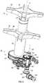
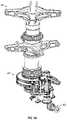
- FIG. 4is a perspective view of a gearbox and translational thrust system in an exemplary embodiment
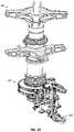
- FIG. 5is a perspective view of a rotor hub fairing in an exemplary embodiment
- FIG. 6depicts a flight control system in an exemplary embodiment
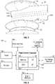
- FIG. 6Adepicts a blade proximity detection system in an exemplary embodiment
- FIG. 7depicts a flight maneuver in an exemplary embodiment
- FIG. 8depicts front, side and top views of an aircraft in an exemplary embodiment
- FIG. 9depicts an active vibration control (AVC) system in an exemplary embodiment
- FIGS. 10 and 11illustrate force vectors in exemplary hover states
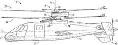
- FIG. 1depicts an exemplary embodiment of a rotary wing, vertical takeoff and land (VTOL) aircraft 10 .
- the aircraft 10includes an airframe 12 with an extending tail 14 .
- a dual, counter rotating, coaxial main rotor assembly 18is located at the airframe 12 and rotates about a main rotor axis, A.
- the airframe 12includes two seats for flight crew (e.g., pilot and co-pilot) and six seats for passengers.
- the main rotor assembly 18is driven by a power source, for example, one or more engines 24 via a gearbox 26 .
- the main rotor assembly 18includes an upper rotor assembly 28 driven in a first direction (e.g., counter-clockwise) about the main rotor axis, A, and a lower rotor assembly 32 driven in a second direction (e.g., clockwise) about the main rotor axis, A, opposite to the first direction (i.e., counter rotating rotors).
- Each of the upper rotor assembly 28 and the lower rotor assembly 32includes a plurality of rotor blades 36 secured to a rotor hub 38 .
- the aircraft 10further includes a translational thrust system 40 located at the extending tail 14 to provide translational thrust (forward or rearward) for aircraft 10 .
- FIG. 2Adepicts a planform of a rotor blade 36 in an exemplary embodiment.
- the rotor assembly 18includes a rotor hub fairing 37 generally located between and around the upper and lower rotor assemblies such that the rotor hubs 38 are at least partially contained therein.
- the rotor hub fairing 37provides drag reduction.
- Rotor blades 36are connected to the upper and lower rotor hubs 38 in a hingeless manner, also referred to as a rigid rotor system.
- a particular aircraft configurationis illustrated in this non-limiting embodiment, other rotary-wing aircraft will also benefit from embodiments of the invention.
- the dual rotor systemis depicted as coaxial, embodiments include dual rotor aircraft having non-coaxial rotors.
- the translational thrust system 40includes a propeller 42 connected to and driven by the engine 24 via the gearbox 26 .
- the translational thrust system 40may be mounted to the rear of the airframe 12 with a translational thrust axis, T, oriented substantially horizontal and parallel to the aircraft longitudinal axis, L, to provide thrust for high-speed flight.
- the translational thrust axis, Tcorresponds to the axis of rotation of propeller 42 . While shown in the context of a pusher-prop configuration, it is understood that the propeller 42 could also be more conventional puller prop or could be variably facing so as to provide yaw control in addition to or instead of translational thrust. It should be understood that any such system or other translational thrust systems may alternatively or additionally be utilized.
- Alternative translational thrust systemsmay include different propulsion forms, such as a jet engine.
- translational thrust system 40includes a propeller 42 and is positioned at a tail section 41 of the aircraft 10 .
- Propeller 42includes a plurality of blades 47 .
- the pitch of propeller blades 47may be altered to change the direction of thrust (e.g., forward or rearward).
- the tail section 41includes active elevators 43 and active rudders 45 as controllable surfaces.
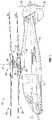
- FIG. 3Shown in FIG. 3 is a perspective view of portions of main rotor assembly 18 and gearbox 26 .
- the gearbox 26includes an upper bull gear 44 , which rotates about the main rotor axis, A, and connected to the lower rotor assembly 32 via a lower rotor shaft 46 extending along the main rotor axis, A.
- a lower bull gear 48which rotates about the main rotor axis, A, and is connected to the upper rotor assembly 28 via an upper rotor shaft 50 extending along the main rotor axis, A, and through an interior of the lower rotor shaft 46 .
- Torque and rotational speedare provided to the gearbox 26 via input shaft 52 that transmits the torque and rotational speed from the engine(s) 24 to an input bevel 54 disposed at an input bevel shaft 56 of the gearbox 26 via an input bevel pinion 104 .
- the input bevel shaft 56rotates about an input bevel shaft axis 58 parallel to the main rotor axis A.
- the propeller 42is driven by a propeller output shaft 106 driven by a propeller output gear 62 disposed at a quill shaft 102 , or an extension of input bevel shaft 56 . Transfer from the propeller output gear 62 is achieved via connection with a propeller output pinion 60 at the propeller output shaft 106 .
- the gearbox 26includes a torque split gear reduction stage 64 .
- the torque split gear reduction stage 64splits torque from the input shaft 52 and applies the divided torque to bull gears 44 and 48 , respectively. While shown with the propeller output shaft 106 driven by the propeller output gear 62 , it is understood that such elements could be removed where the propeller 42 is not used or is separately driven.
- FIG. 3Aillustrates power distribution through gearbox 26 to main rotor assembly 18 and propeller output shaft 106 during hover mode.
- powerflows to torque split section to drive main rotor assembly 18 .
- the propeller output shaft 106spins at all times to drive features on propeller box while propeller 42 is unclutched.
- hover modethe majority of power flows to the main rotor assembly 18 .
- FIG. 3Billustrates power distribution through gearbox 26 to main rotor assembly 18 and propeller output shaft 106 during cruise mode. In high speed cruise, the majority of power flows to the propeller output shaft 106 while the main rotor assembly 18 is operating near an autorotative state.
- the main rotor assembly 18is driven about the axis of rotation, A, through a main gearbox (MGB) 26 by a multi-engine powerplant system 24 , having two engine packages ENG 1 , ENG 2 in the example in FIG. 4 .
- FIG. 4depicts two engines 24 , it is understood that aircraft 10 may use a single engine 24 , or any number of engines.
- the multi-engine powerplant system 24generates power available for flight operations and couples such power to the main rotor assembly 18 and the translational thrust system 40 through the MGB 26 .
- the MGB 26may be interposed between the powerplant system 24 , the main rotor assembly 18 and the translational thrust system 40 .
- a portion of the drive systemsuch as downstream of the MGB 26 for example, includes a gearbox 90 (also referred to as a clutch).
- the combined gearbox 90selectively operates as a clutch and a brake for operation of the translational thrust system 40 with the MGB 26 .
- the gearbox 90also operates to provide a rotor brake function for the main rotor assembly 18 .
- the combined gearbox 90generally includes an input 92 and an output 94 generally defined along an axis parallel to rotational axis, T.
- the input 92is generally upstream of the combined gearbox 90 relative the MOB 26 and the output 94 is downstream of the combined gearbox 90 and upstream of the pusher propeller system 40 ( FIG. 2 ).
- the combined gearbox 90may be categorized by the technique used to disengage-engage (e.g., clutch) or stop (e.g., brake) the load such as friction, electromagnetic, mechanical lockup, etc., and by the method used to actuate such as mechanical, electric, pneumatic, hydraulic, self-activating, etc. It should be understood that various combined gearbox 90 systems may be utilized to include but not to be limited to mechanical, electrically, hydraulic and various combinations thereof.
- Rotor hub fairing 37is illustrated having generally elliptical, in cross-section, upper and lower hub fairings 111 and 112 , and an airfoil-type shape (in horizontal cross-section) for the shaft fairing 103 .
- the airfoil shape of the shaft fairing 103includes a leading edge 114 , and a trailing edge 115 aft of the upper and lower fairings 111 , 112 .
- the airfoil shape of the shaft fairing 103additionally includes a chord (not shown) that connects the leading and trailing edges 114 , 115 of the airfoil.
- the airfoil shapeincluding the upper surface 116 and the lower surface 117 , is symmetrical about a plane extending along the length of the shaft fairing 103 and containing the axis of rotation, A.
- the upper and lower rotor hubs 38may be positioned, at least partially, in the upper and lower fairings 111 , 112 .
- a flight control system 120is a fly-by-wire (FBW) control system.
- FBWfly-by-wire
- a FBW control systemincludes a plurality of sensors 122 which can sense the position of controlled elements and generate electrical signals proportional to the sensed position.
- the sensors 122may also be used directly and indirectly to provide a variety of aircraft state data to a flight control computer (FCC) 124 .
- the FCC 124may also receive inputs 126 as control commands from various sources.
- the inputs 126can be pilot inputs, auto-pilot inputs, navigation system based inputs, or any control inputs from one or more control loops executed by the FCC 124 or other subsystems.
- the FCC 124transmits signals to various subsystems of the aircraft 10 .
- Flight control system 120may include a rotor interface 128 configured to receive commands from the FCC 124 and control one or more actuators, such as a mechanical-hydraulic or electric actuators, for the upper rotor assembly 28 and lower rotor assembly 32 .
- actuatorssuch as a mechanical-hydraulic or electric actuators
- inputs 126 including cyclic, collective, pitch rate, and throttle commandsthat may result in the rotor interface 128 driving the one or more actuators to adjust upper and lower swashplate assemblies (not depicted) for pitch control of the upper rotor assembly 28 and lower rotor assembly 32 .
- pitch controlcan be performed without a swashplate assemblies using individual blade control (IBC) in the upper rotor assembly 28 and lower rotor assembly 32 .
- the rotor interface 128can manipulate the upper rotor assembly 28 and lower rotor assembly 32 independently. This allows different collective and cyclic commands to be provided to the upper rotor assembly 28 and lower rotor assembly 32 .
- Flight control system 120may include a translational thrust interface 130 configured to receive commands from the FCC 124 to control one or more actuators, such as a mechanical-hydraulic or electric actuators, for the control of the translational thrust system 40 .
- actuatorssuch as a mechanical-hydraulic or electric actuators
- inputs 126may result in the translational thrust interface 130 controlling speed of propeller 42 , altering the pitch of propeller blades 47 (e.g., forward or rearward thrust), altering the direction of rotation of propeller 42 , controlling gearbox 90 to employ a clutch 91 to engage or disengage the propeller 42 , etc.
- Flight control system 120may include a tail fairing interface 132 .
- the tail fairing interface 132is configured to receive commands from the FCC 124 to control one or more actuators, such as a mechanical-hydraulic or electric actuators, for the active elevator 43 and/or active rudders 45 of FIG. 2 .
- inputs 126include an elevator pitch rate command for the tail fairing interface 132 to drive the one or more actuators for pitch control of the active elevators 43 of FIG. 2 .
- inputs 126include a rudder command for the tail fairing interface 132 to drive the one or more actuators for positional control of the active rudders 45 of FIG. 2 .
- Flight control system 120may include an engine interface 133 .
- the engine interface 133is configured to receive commands from the FCC 124 to control engine(s) 24 .
- inputs 126include a throttle command from the pilot to adjust the RPM of engine(s) 24 .
- FCC 124may also send commands to engine interface 133 to control the engine(s) in certain predefined operating modes (e.g., quiet mode).
- the FCC 124includes a processing system 134 that applies models and control laws to augment commands based on aircraft state data.
- the processing system 134includes processing circuitry 136 , memory 138 , and an input/output (I/O) interface 140 .
- the processing circuitry 136may be any type or combination of computer processors, such as a microprocessor, microcontroller, digital signal processor, application specific integrated circuit, programmable logic device, and/or field programmable gate array, and is generally referred to as central processing unit (CPU) 136 .
- the memory 138can include volatile and non-volatile memory, such as random access memory (RAM), read only memory (ROM), or other electronic, optical, magnetic, or any other computer readable storage medium onto which data and control logic as described herein are stored.
- the memory 138is a tangible storage medium where instructions executable by the processing circuitry 136 are embodied in a non-transitory form.
- the I/O interface 140can include a variety of input interfaces, output interfaces, communication interfaces and support circuitry to acquire data from the sensors 122 , inputs 126 , and other sources (not depicted) and communicate with the rotor interface 128 , the translation thrust interface 130 , tail fairing interface 132 , engine interface 133 , and other subsystems (not depicted).
- the rotor interface 128under control of the FCC 124 , can control the upper rotor assembly 28 and lower rotor assembly 32 to pitch in different magnitudes and/or different directions at the same time.
- Differential pitch controlalso includes differential cyclic pitch control, where the upper rotor assembly 28 has a cyclic pitch different than the cyclic pitch of the lower rotor assembly 32 , in magnitude, axis of orientation (e.g., longitudinal or lateral) and/or direction.
- differential collective and the differential cyclic pitch controlmay be accomplished using independently controlled swashplates in the upper rotor assembly 28 and lower rotor assembly 32 .
- differential collective and the differential cyclic pitch controlmay be accomplished using individual blade control in the upper rotor assembly 28 and lower rotor assembly 32 .
- the ability to independently control the pitch of the upper rotor assembly 28 and lower rotor assembly 32allows the lower rotor assembly 32 to be adjusted due to its position beneath the upper rotor assembly 28 .
- the lower rotor assembly 32is located in the downwash of the upper rotor assembly 28 .
- the lower rotor assembly 32may have a collective pitch that differs from the collective pitch of the upper rotor assembly 28 .
- the counter rotating rotor headsbalance out the torque generated by each rotor head and also balances the lift generated by each advancing blade without the need for blade flapping or reducing the speed of the aircraft, or the need for a wing.
- Thisis made possible by the rigid rotor system.
- Rigid rotorsallow for a reduced spacing between rotors. With two rigid rotors, the roll moments cancel at the main rotor shaft. Other rotor systems can generate opposing head moments, however, a greater spacing is required between rotors of those systems.
- upper rotor assembly 28 and lower rotor assembly 32allows the pre-cone angle to be set on each individual rotor to reduce bending stress on the blades.
- the hingeswill naturally go to an angle to reduce bending stress.
- a useful pre-cone angleis one where the centrifugal force of the blade pulling out matches the lift of the blade up. Due to the independent nature of the upper rotor assembly 28 and lower rotor assembly 32 , differential pre-cone is used in aircraft 10 .
- Differential pre-conerefers to the fact that the upper rotor assembly 28 and lower rotor assembly 32 have different pre-cone angles.
- the different pre-cone angles for the upper rotor assembly 28 and lower rotor assembly 32help maintain tip clearance.
- the pre-angle on the upper rotor assembly 28is about 3 degrees and the pre-cone angle on the lower rotor assembly 32 is about 2 degrees.
- Aircraft 10is operational in a variety of modes, including take-off, cruise, landing, etc.
- Cruise moderefers to generally horizontal flight. During cruise, aircraft 10 can reach speeds of above about 200 knots, with speed reaching up to about 250 knots.
- the main rotor assembly 18provides the majority of lift for the aircraft. In exemplary embodiments and flight modes, the main rotor assembly 18 provides greater than about 85% of the lift during cruise mode.
- Aircraft 10may assume various acoustic modes, depending on the flight state.
- FCC 124may control RPM of engines 24 , RPM of propeller 42 , and gearbox 90 to engage or disengage the propeller 42 to assume different noise levels. For example, at take-off noise may not be a concern, and there would be no changes in aircraft operation to adjust the noise level.
- the gearbox 90may be disengaged such that the propeller 42 is decoupled from the main rotor system 18 to improve ground safety. As the aircraft approaches a target, it may be desirable to disengage the propeller 42 from the main rotor assembly 18 using gearbox 90 and/or reduce RPM of engines 24 to reduce the noise produced by aircraft 10 .
- the propeller 42may be disengaged at various other flight states (e.g., low speed cruise) to reduce noise.
- the RPM of the main rotor assembly 18 and RPM of propeller 42may be independently controlled (e.g., through gearbox 90 or FCC 124 ). This allows a variety of flight states to be achieved.
- the pilotmay enter separate commands to reduce aircraft noise, for example, disengaging the propeller 42 , reducing engine RPM, and increasing collective pitch as separate inputs.
- the pilotmay select a reduced noise mode (e.g., quiet mode) through single input, and the FCC 124 controls the various aircraft interfaces to achieve the desired mode.
- the pilotmay select a reduced noise mode at input 126 , and the FCC automatically disengages the propeller 42 , reduces the engine 24 RPM and/or increases collective pitch without further demand on the pilot.
- the use of the translational thrust system 40allows the aircraft 10 to move forward or rearward (depending on the pitch of the propeller blades) independent of the pitch attitude of the aircraft. Cyclic is used to adjust the pitch attitude (nose up, nose down or level) of the aircraft while the translational thrust system 40 provides forward and rearward thrust.
- the motor rotor assembly 18 system and the translational thrust system 40are connected through the main gearbox 26 .
- a gear ratio of main gearbox 26is selected so as to keep propeller 42 at a high efficiency and suitable noise level during cruise mode.
- the gear ratio of main gearbox 26dictates the ratio of the rotor speed of main rotor assembly 18 to propeller speed of propeller 42 .
- Embodiments of aircraft 10provide the pilot with increased situational awareness by allowing the aircraft attitude (e.g., the angle of longitudinal axis, L, relative to horizontal) to be adjusted by cyclic pitch of the main rotor assembly 18 and the forward and rearward thrust to be controlled by the translational thrust system 40 .
- Thisallows a variety of flight modes to be achieved, which allows the pilot to be more aware of their surroundings.
- Aircraft 10can take off at a horizontal attitude (e.g., axis L is horizontal), which also may be referred to as vertical take-off.
- Aircraft 10may also fly forward or cruise with the nose angled upwards, nose angled downwards or level.
- Aircraft 10can hover with the nose angled upwards or downwards or level.
- Aircraft 10 and 11illustrate force vectors from the main rotor assembly and propeller for hover nose up and hover nose down, respectively.
- Aircraft 10can also land substantially parallel to a non-horizontal or sloped surface by adjusting the attitude of the aircraft using cyclic pitch of the main rotor assembly 18 .
- the use of main rotor assembly 18 for aircraft attitude and the translational thrust system 40 for thrustallows aircraft 10 to assume a variety of trim states.
- Embodimentsprovide independent control of the active elevators 43 and/or active rudders 45 as controllable surfaces in the tail section 41 .
- the elevator surfaces 43may be controlled independently by the FCC 124 through the tail fairing interface 132 .
- the rudder surfaces 45may be controlled independently by the FCC 124 through the tail fairing interface 132 .
- aircraft 10can achieve a bank angle of about 60 degrees at about 210 knots.
- Aircraft 10may make use of longitudinal lift offset in trim to compensate for rotor-on-rotor aerodynamic interaction between the upper rotor assembly 28 and lower rotor assembly 32 .
- Aircraft 10may adjust differential longitudinal cyclic as a function of operational states of the aircraft (e.g., take-off, cruise, land, etc.). Differential longitudinal cyclic refers to upper rotor assembly 28 and lower rotor assembly 32 having different cyclic pitch along the longitudinal axis of the aircraft. Differential longitudinal cyclic may also be used to generate yaw moments.
- Lift offsetmay be used to control aircraft, where lateral lift offset adjusts roll and longitudinal lift offset adjusts pitch.
- FCC 124may control RPM of engine(s) 24 , RPM of propeller 42 , and gearbox 90 to engage or disengage the propeller 42 to assume different noise levels. For example, at take-off noise may not be a concern, and there would be no changes in aircraft operation to adjust the noise level. As the aircraft approaches a target, it may be desirable to disengage the propeller 42 using gearbox 90 and/or reduce RPM of engines 24 to reduce the noise produced by aircraft 10 .
- the propeller 42may be disengaged at various other flight states (e.g., high speed) to reduce noise.
- the RPM of the main rotor assembly 18 and RPM of propeller 42may be independently controlled (e.g., through gearbox 90 ).
- the pilotmay enter separate commands to reduce aircraft noise, for example, disengaging the propeller 42 and reducing engine RPM as separate inputs.
- the pilotmay select a reduced noise mode (e.g., quiet mode) through single input, and the FCC 124 controls the various aircraft interfaces to achieve the desired mode.
- the pilotmay select a reduced noise mode at input 126 , and the FCC automatically disengages the propeller 42 and/or reduces the engine 24 RPM without further demand on the pilot.
- Aircraft 10provides the ability to approach a target and reverse thrust while maintaining an attitude directed at the target.
- FIG. 7depicts aircraft 10 approaching a target 200 .
- the aircraft 10alters the pitch of blades 47 in propeller 42 to provide reverse thrust to bring the aircraft to a quick stop.
- the main rotor assembly 18 and propeller 42are controlled to pitch aircraft 10 towards target 200 .
- the propeller 42is used to provide reverse thrust to move away from target 200 and climb, while still maintaining an attitude with the nose of aircraft 10 facing target 200 .
- the use of a dual rotor system and translational thrustallows aircraft 10 to eliminate the need for a variable angle between the main axis of rotation of the rotor system (e.g., axis A in FIG. 1 ) and aircraft longitudinal axis L.
- the angle between the main axis of rotation of the rotor system and the aircraft longitudinal axis Lvaries. This is due to the fact that conventional helicopters lack a translational thrust system 40 for use during cruise mode, or forward flight.
- forward flightis provided through cyclic pitch, which causes the aircraft to point nose down. As this nose down orientation is undesirable beyond a certain angle, the angle between the main axis of rotation of the rotor system and the aircraft longitudinal axis L is adjusted to bring the nose upwards, while still in forward flight.
- aircraft 10with translational thrust system 40 , does not need to adjust the angle between the main axis of rotation of the rotor system (e.g., axis A in FIG. 1 ) and aircraft longitudinal axis L.
- the angle between the main axis of rotation of the rotor system (e.g., axis A in FIG. 1 ) and aircraft longitudinal axis L for aircraft 10remains fixed during all flight modes, including take-off, cruise, landing, etc, unless otherwise commanded by a pilot of the aircraft 10 .
- the rotor assembly 18includes a rotor hub fairing 37 generally located between and around the upper and lower rotor assemblies such that the rotor hubs 38 are at least partially contained therein.
- the rotor hub fairing 37provides drag reduction.
- FIG. 5an exemplary rotor hub fairing 37 is shown.
- Rotor hub fairing 37is illustrated having generally elliptical, in cross-section, upper and lower hub fairings 111 and 112 , and an airfoil-type shape (in horizontal cross-section) for the shaft fairing 103 .
- the airfoil shape of the shaft fairing 103includes a leading edge 114 , and a trailing edge 115 aft of the upper and lower fairings 111 , 112 .
- the airfoil shape of the shaft fairing 103additionally includes a chord (not shown) that connects the leading and trailing edges 114 , 115 of the airfoil.
- the airfoil shape, including the upper surface 116 and the lower surface 117is symmetrical about a plane extending along the length of the shaft fairing 103 and containing the axis of rotation, A.
- the upper and lower rotor hubs 38may be positioned, at least partially, in the upper and lower fairings 111 , 112 .
- the rotor hub fairing 37is a sealed fairing, meaning there are few or no passages for air to travel through the interior of the rotor hub fairing 37 .
- control devicessuch as pushrods
- the surfaces of these componentsincrease drag on the rotor assembly.
- the air gaps between various rotor structurese.g., pushrods and main rotor shaft
- the sealed rotor hub fairing 37eliminates air pathways through the rotor hub structure, and eliminates drag associated with such air paths.
- FIG. 3Another feature to reduce drag on the rotor hub is positioning control rods, such as push rods for rotor control, internal to the main rotor shaft.
- pushrods for swashplates in the upper rotor assembly 28 and lower rotor assembly 32are located internal to the lower rotor shaft 46 and upper rotor shaft 50 . This prevents the pushrods from being exposed and increasing drag on the rotor hub.
- the use of a rigid rotor systemaids in sealing the rotor hub fairing 37 .
- the distance between the hub of the upper rotor assembly 28 and the hub of the lower rotor assembly 32ranges from about 2 feet to about 2.5 feet. In another exemplary embodiment, the distance between the hub of the upper rotor assembly 28 and the hub of the lower rotor assembly 32 ranges from about 2.1 feet to about 2.4 feet. In another exemplary embodiment, the distance between the hub of the upper rotor assembly 28 and the hub of the lower rotor assembly 32 is about 2.29 feet (0.7 meters).
- Aircraft 10may employ an active vibration control (AVC) system to reduce vibration in the airframe 12 .
- AVCactive vibration control
- FIG. 9depicts an AVC system in an exemplary embodiment.
- An AVC controller 300executes an AVC control process to reduce vibration in aircraft 10 .
- AVC controller 300may be implemented as part of flight control system 120 , executed by FCC 124 , or may be a separate controller.
- One or more sensors 302are located in aircraft 10 to detect vibration. Sensors may be located in a wide variety of positions, including airframe 12 , gearbox 26 , tail section 14 , on main rotor assembly 18 , cockpit, etc.
- AVC actuators 304generate a force to dampen vibration in aircraft 10 , as known in the art.
- AVC actuators 304may be located in any position in the aircraft.
- AVC controller 300receives vibration signals from the AVC sensors 302 .
- AVC controller 300provides control signals to the AVC actuators 304 to generate forces to reduce the vibration sensed by the AVC sensors 302 .
- Control signals to the AVC actuators 304may vary in magnitude and frequency to cancel vibrations in aircraft 10 .
- AVC controller 300operates in a feedback mode, where the control signals to AVC actuators 304 are adjusted in response to measured vibration from AVC sensors 302 .
- AVC controller 300does not actively measure vibration through AVC sensors 302 . Rather, the AVC controller 300 obtains the rotor speed (e.g., through an RPM signal) and applies a control signal to the AVC actuators 304 , in an open loop control mode.
- a first speede.g. 40 knots
- the FCC 124uses differential collective pitch for yaw control.
- a second speede.g. 80 knots
- a mix of differential collective and differential cyclicmay be used to control yaw.
- the differential cyclicmay be applied along the longitudinal and/or lateral axes of the aircraft. Further, wind direction may be measured by a sensor 122 and used to adjust the differential cyclic about the longitudinal and/or lateral axes.
- the active rudders 45are used as controllable surfaces to control yaw.
- the FCC 124provides commands to the tail fairing interface 132 to control the rudders 45 to adjust yaw.
- Flight control system 120performs mixing of collective pitch of main rotor assembly 18 and an angle of elevator 43 to provide stability augmentation.
- FIG. 6Adepicts a blade proximity monitoring system in an exemplary embodiment. At least one upper rotor blade and at least one lower rotor blade is equipped with at least one antenna 502 .
- Antennas 502may be electric field antennas or magnetic field antennas. Antennas 502 may be implemented using compact ferrite core or small diameter magnet wire in the form of coils around the blade spar or embedded in the plane of the blade skin. The antennas 502 interact through the near field effect.
- An oscillator 504sends an excitation signal (e.g., 40 KHz) to a first antenna 502 L. It is understood that the excitation signal may be sent to a plurality of antennas in different blades, including multiple antennas in the same blade. As the blades cross, a second antenna, 502 U, receives a signal emitted by the first antenna 502 L. An output level monitor 506 measures the magnitude of the excitation signal.
- an excitation signale.g. 40 KHz
- a blade proximity monitor 508(e.g., a processor implemented controller) is mounted in the rotating system, e.g., in a rotor hub. This eliminates noise that may be introduced through a conventional slip ring used to convey signals from a rotating system to a stationary system.
- the blade proximity monitor 508receives an output signal from the second antenna 502 U and the magnitude of the excitation signal from the output level monitor 506 . Output signal from the second antenna 502 U may be amplified.
- the blade proximity monitor 508also receives a RPM signal of the main rotor assembly 18 from a contactor 510 .
- blade proximity monitor 508can detect the distance between the first antenna 502 L and the second antenna 502 U. This provides an indication of the distance between the rotor blades. The larger the magnitude of the output signal from second antenna 502 U, the closer the blades.
- the blade proximity monitor 508may output the measured distance between the blades to a rotor track and balance unit 512 .
- the blade proximity monitor 508may output the measured distance between the blades to instrument system 514 and to a pilot display 516 . If the measured distance goes below a threshold, then an alert may be generated to the pilot that the blades of the upper rotor assembly 32 and the lower rotor assembly 28 are too close to each other.
- Flight control system 120allows many improvements in a coaxial rigid rotor helicopter such as rotor efficiency, aircraft controllability, blade 36 tip clearance, and reduced main rotor assembly 18 loads. Flight control system 120 may apply different control envelopes to the upper rotor assembly 28 and the lower rotor assembly 32 . Flight control system 120 may impose different flight control ranges on the upper rotor assembly 28 and the lower rotor assembly 32 including control elements such as prioritization, ganged vs. differential, collective versus cyclic, etc.
- the upper rotor assembly 28 and the lower rotor assembly 32 of a coaxial helicopterhave had mechanically linked swashplates with similar kinematics, which produced similar control outputs on both the upper rotor assembly 28 and the lower rotor assembly 32 .
- One control input from the pilotwould travel via the same mechanical means to produce a similar response on both the mechanically linked upper rotor assembly 28 and the lower rotor assembly 32 .
- the swashplateswere linked to avoid added weight and complexity from separate upper and lower rotor control linkages and servos that connect the pilot's control input to the movable components that control the upper rotor assembly 28 and the lower rotor assembly 32 .
- the upper rotor assembly 28 and the lower rotor assembly 32do not have to be directly mechanically linked to the pilot's controls or each other.
- a control input 126is received and sent to the flight control system 120 , where one or multiple flight control computers 124 enter the control input 126 and data from sensors 122 into algorithms, which then determines how much control output commands, including cyclic and collective, should be applied to the upper rotor assembly 28 and the lower rotor assembly 32 .
- Sensor datamay include both environmental conditions and aircraft state conditions. Environmental conditions that may be sensed include but are not limited to the following atmospheric air temperature, atmospheric air pressure, atmospheric air density, relative wind speed, weather, terrain, terrain slope, obstacles, targets and proximate flying objects.
- Aircraft state datathat may be sensed include but are not limited to aircraft geolocation, altitude, attitude, speed, weight, center of gravity, vibration, control surface positions, rotor RPM, rotor blade pitch, rotor blade azimuth location, and translational thrust system RPM.
- the flight control computer 124will then impart a control command output on the upper rotor assembly 28 and a separate control command output on the lower rotor assembly 32 .
- the flight control computer 124may limit the collective, lateral cyclic, longitudinal cyclic controls of both the upper rotor assembly 28 and the lower rotor assembly 32 .
- These control commandsmay be limited as ganged, differential, or individual rotor cyclic and collective limits to determine the optimal control commands to send to the upper rotor assembly 28 and the lower rotor assembly 32 .
- the ganged limitis defined as the average of the upper rotor assembly 28 control and the lower rotor assembly 32 control.
- the individual rotor cyclic and collective limitswill account for each rotor assembly separately with no comparison to the other rotor assembly.
- the flight control computer 124may also be configured to prioritize the control command limits such as ganged, differential, independent rotors, or a combination thereof. Some examples of prioritization include but are not limited to ganged collective vs.
- control command outputmay then be limited further by control mechanism limits, which include but are not limited to servo stroke available, swashplate tilt angle limit, blade pitch limit, and interference between control components.
- control rangesare defined as the control envelopes of aircraft 10 .
- Such control envelopesare traditionally expressed in two or three dimensional graphical form and plot one control range against another.
- Some examples of control envelopesinclude but are not limited to a 2D envelope may show cyclic v. collective, or longitudinal cyclic v. lateral cyclic.
- the upper rotor assembly 28 and the lower rotor assembly 32may be independently controlled through the use of separate upper and lower swashplates along with servos. Alternatively, the upper rotor assembly 28 and the lower rotor assembly 32 may be independently controlled using individual blade control (IBC) techniques.
- IBCindividual blade control
- Aircraft 10employs a fly-by-wire (FBW) control system to reduce pilot work load.
- FCC 124determines the aircraft airspeed based on one or more sensors 122 . The FCC 124 then adjusts the collective pitch of the upper rotor assembly 28 and/or the lower rotor assembly 32 in response to the airspeed.
- FCC 124may use a look up table that indexes airspeed to collective pitch.
- FCC 124may use an algorithm to compute the collective pitch based on airspeed. As noted above, the collective pitch of upper rotor assembly 28 and the lower rotor assembly 32 may be the same or different.
- Another feature to reduce pilot workloadincludes automatically adjusting the RPM and/or pitch of propeller 42 in response to a velocity or acceleration command from the pilot.
- Conventional systemswould require the pilot to adjust propeller RPM and/or pitch through individual inputs.
- the flight control system 120allows the pilot to enter a desired velocity or an acceleration, and the FCC 124 generates the proper commands to the translational thrust interface 130 to establish an RPM and/or pitch to meet the desired velocity or acceleration.
- the flight control system 120controls the main rotor assembly 18 to prevent the tips of rotor blades 36 from exceeding a threshold speed.
- the threshold speedmay be Mach 0.9. This threshold would prevent the rotor blade tips from exceeding the speed of sound.
- the threshold speedmay vary, and may be set to limit drag on the rotor blades to below a certain level.
- the FCC 124determines air temperature from sensors 122 . FCC 124 may also determine prevailing wind speed and direction from sensors 122 . The FCC 124 then computes the threshold speed based on the speed of sound (e.g., Mach 1) at the sensed air temperature. The FCC 124 may set the threshold to Mach 0.9, for example.
- FCC 124then controls RPM of the main rotor assembly 18 to prevent the rotor blade tips from exceeding the threshold.
- the FCCmaintain 85% of the nominal rotor RPM.
- FCC 124may take into account prevailing wind direction and speed in controlling the RPM of the main rotor assembly 18 .
- the Mach 0.9 thresholdis only one example, and other speed thresholds may be employed to achieve desired results (e.g., reduce drag).
- active elevator 43is configured and controlled to improve stability by compensating for forces such as propeller torque and/or rotor downwash.
- Elevator 43includes a left elevator and a right elevator on opposite sides of the axis of rotation of the propeller 42 .
- the left elevator and right elevatormay be independently controlled to assume different positions.
- the tail fairing interface 132is configured to receive commands from the FCC 124 to control one or more actuators, such as a mechanical-hydraulic or electric actuators, to position the left elevator and right elevator independently. This independent control of the left elevator and right elevator aids in compensating propeller torque and/or rotor downwash.
- the left elevator and right elevatormay also have different physical configurations to compensate for compensating propeller torque and/or rotor downwash.
- the left elevator and right elevatormay be offset relative to each other along the longitudinal and/or lateral axes of aircraft 10 . Further, the left elevator and right elevator may have different geometries where one of the left elevator and right elevator is larger than the other along the longitudinal and/or lateral axes of aircraft 10 .
- the left elevator and right elevatormay have differing aerodynamic surfaces (e.g., airfoils) as well.
- the cockpit of aircraftincludes a single, semi-active, collective input (e.g., stick) positioned between the two pilot seats.
- a single, semi-active, collective inpute.g., stick
- FIG. 8presents front, side and top views of an exemplary aircraft.
- One feature contributing to the reduced footprintis the location of the main rotor shaft relative to the airframe 12 .
- the axis of rotation A, of the main rotor assembly 18intersects longitudinal axis, L, along a span of axis L, extending from the nose of the aircraft to the tip of the hub of propeller 42 .
- the axis of rotation Ais located at about a 44% station (STA) of the fuselage or airframe 12 .
- STAstation
- the rotor blades 36extend beyond the nose of the aircraft by about 13 inches (0.33 meters). In an exemplary embodiment, rotor blades 36 extend beyond the nose of the aircraft by about 6.9% of the blade span, which may be about 188 inches.
- the use of a rigid rotor system, along with the rotor shaft position (e.g., axis A)allows for much easier air-to-air refueling.
- the stiff rotor blades 36ease air-to-air refueling by reducing blade flapping, which may result in a blade contacting a tanker fuel line during refueling.
- Aircraft 10provides an improved glide slope ratio of about 5-to-1 to about 6-to-1. This is due to the propeller 42 taking energy out of the airstream, inputting energy into the gear box 26 to increase the speed of the main rotor assembly 18 during autorotation. As shown in FIGS. 3 and 4 , the main gear box 26 interconnects the main rotor assembly 18 and propeller 42 . During autorotation, the airflow rotates propeller 42 , which will subsequently rotate the main rotor assembly 18 and thus increase lift. Propeller 42 also helps stabilize aircraft 10 during decent by acting like a parachute and a rudder, both slowing aircraft 10 and helping to direct aircraft 10 to maintain control. The ability to fly aircraft 10 in a nose down attitude also improves glide slope ratio.
- the distance between the hub of the upper rotor assembly 28 and the hub of the lower rotor assembly 32ranges from about 2 feet to about 2.5 feet. In another exemplary embodiment, the distance between the hub of the upper rotor assembly 28 and the hub of the lower rotor assembly 32 ranges from about 2.1 feet to about 2.4 feet. In another exemplary embodiment, the distance between the hub of the upper rotor assembly 28 and the hub of the lower rotor assembly 32 is about 2.29 feet. In another exemplary embodiment, the distance between a midpoint of a blade in the upper rotor assembly 28 and a midpoint of a blade in the lower rotor assembly 32 is about 29.0 inches.
- the distance between a tip of a blade in the upper rotor assembly 28 and a tip of a blade in the lower rotor assembly 32is about 31.0 inches. In another exemplary embodiment, the distance between the hub of the upper rotor assembly 28 and the hub of the lower rotor assembly 32 is about 14% of the blade span, which may be about 188 inches.
Landscapes
- Engineering & Computer Science (AREA)
- Aviation & Aerospace Engineering (AREA)
- Mechanical Engineering (AREA)
- Automation & Control Theory (AREA)
- Physics & Mathematics (AREA)
- Radar, Positioning & Navigation (AREA)
- Remote Sensing (AREA)
- General Physics & Mathematics (AREA)
- General Engineering & Computer Science (AREA)
- Fluid Mechanics (AREA)
- Acoustics & Sound (AREA)
- Toys (AREA)
- Control Of Position, Course, Altitude, Or Attitude Of Moving Bodies (AREA)
- Turbine Rotor Nozzle Sealing (AREA)
- Details Of Aerials (AREA)
- Tires In General (AREA)
- Wind Motors (AREA)
- Structures Of Non-Positive Displacement Pumps (AREA)
- Control Of Turbines (AREA)
- Navigation (AREA)
- Transmission Devices (AREA)
- Regulating Braking Force (AREA)
- Mixers Of The Rotary Stirring Type (AREA)
- Automatic Assembly (AREA)
Abstract
Description
Claims (16)
Priority Applications (1)
| Application Number | Priority Date | Filing Date | Title |
|---|---|---|---|
| US15/504,525US11440650B2 (en) | 2014-10-01 | 2015-09-30 | Independent control for upper and lower rotor of a rotary wing aircraft |
Applications Claiming Priority (3)
| Application Number | Priority Date | Filing Date | Title |
|---|---|---|---|
| US201462058424P | 2014-10-01 | 2014-10-01 | |
| US15/504,525US11440650B2 (en) | 2014-10-01 | 2015-09-30 | Independent control for upper and lower rotor of a rotary wing aircraft |
| PCT/US2015/053095WO2016054139A2 (en) | 2014-10-01 | 2015-09-30 | Independent control for upper and lower rotor of a rotary wing aircraft |
Publications (2)
| Publication Number | Publication Date |
|---|---|
| US20170233067A1 US20170233067A1 (en) | 2017-08-17 |
| US11440650B2true US11440650B2 (en) | 2022-09-13 |
Family
ID=55631217
Family Applications (32)
| Application Number | Title | Priority Date | Filing Date |
|---|---|---|---|
| US15/503,633AbandonedUS20170267338A1 (en) | 2014-10-01 | 2015-06-18 | Acoustic signature variation of aircraft utilizing a clutch |
| US15/503,599AbandonedUS20170225797A1 (en) | 2014-10-01 | 2015-07-01 | Aircraft design for air to air refueling |
| US15/513,301Active2036-04-09US10527123B2 (en) | 2014-10-01 | 2015-07-14 | Rotorcraft footprint |
| US15/514,115ActiveUS10443674B2 (en) | 2014-10-01 | 2015-07-27 | Noise modes for rotary wing aircraft |
| US15/515,040Active2036-05-10US10443675B2 (en) | 2014-10-01 | 2015-08-06 | Active vibration control of a rotorcraft |
| US15/508,321AbandonedUS20170283049A1 (en) | 2014-10-01 | 2015-08-07 | Differential pre-cone rotary wing arrangement and aircraft |
| US15/509,450AbandonedUS20170274990A1 (en) | 2014-10-01 | 2015-09-24 | Rotor hover figure of merit for rotary wing aircraft |
| US15/509,446AbandonedUS20170277201A1 (en) | 2014-10-01 | 2015-09-24 | Nose attitude control of a rotary wing aircraft |
| US15/507,178Active2036-10-08US10676181B2 (en) | 2014-10-01 | 2015-09-25 | Gearbox for a dual rotor, rotary wing aircraft |
| US15/500,388AbandonedUS20170220048A1 (en) | 2014-10-01 | 2015-09-25 | Rotary wing aircraft and method of controlling a rotary wing aircraft |
| US15/508,378AbandonedUS20170305534A1 (en) | 2014-10-01 | 2015-09-28 | Rotorcraft systems to reduce pilot workload |
| US15/509,741Active2036-10-29US10717521B2 (en) | 2014-10-01 | 2015-09-28 | Hub separation in dual rotor rotary wing aircraft |
| US15/508,991AbandonedUS20170283045A1 (en) | 2014-10-01 | 2015-09-28 | Translation thrust system engagement and disengagment for rotary wing aircraft |
| US15/515,897AbandonedUS20170297692A1 (en) | 2014-10-01 | 2015-09-28 | Rotary wing aircraft |
| US15/514,881AbandonedUS20170217581A1 (en) | 2014-10-01 | 2015-09-29 | Blade indexing of a rotary wing aircraft |
| US15/515,949AbandonedUS20180231986A1 (en) | 2014-10-01 | 2015-09-29 | Aircraft with speed or acceleration command |
| US15/509,755AbandonedUS20170297696A1 (en) | 2014-10-01 | 2015-09-29 | Aircraft main rotor drag to airframe drag |
| US15/501,095Active2036-03-27US10654565B2 (en) | 2014-10-01 | 2015-09-29 | Collective to elevator mixing of a rotary wing aircraft |
| US15/514,595Active2036-02-10US11021241B2 (en) | 2014-10-01 | 2015-09-29 | Dual rotor, rotary wing aircraft |
| US15/508,346ActiveUS10167079B2 (en) | 2014-10-01 | 2015-09-29 | Main rotor rotational speed control for rotorcraft |
| US15/504,227Active2037-01-24US11040770B2 (en) | 2014-10-01 | 2015-09-30 | Single collective stick for a rotary wing aircraft |
| US15/504,525Active2037-10-20US11440650B2 (en) | 2014-10-01 | 2015-09-30 | Independent control for upper and lower rotor of a rotary wing aircraft |
| US15/515,882AbandonedUS20170305544A1 (en) | 2014-10-01 | 2015-09-30 | Turn radius and bank angle for rotary wing aircraft |
| US15/516,271AbandonedUS20170297694A1 (en) | 2014-10-01 | 2015-09-30 | Rotor speed management |
| US15/501,100Active2036-04-24US10400851B2 (en) | 2014-10-01 | 2015-09-30 | Tip clearance measurement of a rotary wing aircraft |
| US15/510,131AbandonedUS20170349275A1 (en) | 2014-10-01 | 2015-09-30 | Elevator and rudder control of a rotorcraft |
| US15/504,256AbandonedUS20170308101A1 (en) | 2014-10-01 | 2015-09-30 | Aircraft and method of orienting an airframe of an aircraft |
| US15/503,617ActiveUS10619698B2 (en) | 2014-10-01 | 2015-09-30 | Lift offset control of a rotary wing aircraft |
| US15/501,376AbandonedUS20170225775A1 (en) | 2014-10-01 | 2015-09-30 | Rotorcraft operational altitude and airspeed |
| US15/504,250Active2036-04-21US10640203B2 (en) | 2014-10-01 | 2015-10-01 | Rotorcraft rotor and propeller speed |
| US15/516,080AbandonedUS20170305543A1 (en) | 2014-10-01 | 2015-10-01 | Sealed hub and shaft fairing for rotary wing aircraft |
| US16/010,615AbandonedUS20190017569A1 (en) | 2014-10-01 | 2018-06-18 | Elevator and rudder control of a rotorcraft |
Family Applications Before (21)
| Application Number | Title | Priority Date | Filing Date |
|---|---|---|---|
| US15/503,633AbandonedUS20170267338A1 (en) | 2014-10-01 | 2015-06-18 | Acoustic signature variation of aircraft utilizing a clutch |
| US15/503,599AbandonedUS20170225797A1 (en) | 2014-10-01 | 2015-07-01 | Aircraft design for air to air refueling |
| US15/513,301Active2036-04-09US10527123B2 (en) | 2014-10-01 | 2015-07-14 | Rotorcraft footprint |
| US15/514,115ActiveUS10443674B2 (en) | 2014-10-01 | 2015-07-27 | Noise modes for rotary wing aircraft |
| US15/515,040Active2036-05-10US10443675B2 (en) | 2014-10-01 | 2015-08-06 | Active vibration control of a rotorcraft |
| US15/508,321AbandonedUS20170283049A1 (en) | 2014-10-01 | 2015-08-07 | Differential pre-cone rotary wing arrangement and aircraft |
| US15/509,450AbandonedUS20170274990A1 (en) | 2014-10-01 | 2015-09-24 | Rotor hover figure of merit for rotary wing aircraft |
| US15/509,446AbandonedUS20170277201A1 (en) | 2014-10-01 | 2015-09-24 | Nose attitude control of a rotary wing aircraft |
| US15/507,178Active2036-10-08US10676181B2 (en) | 2014-10-01 | 2015-09-25 | Gearbox for a dual rotor, rotary wing aircraft |
| US15/500,388AbandonedUS20170220048A1 (en) | 2014-10-01 | 2015-09-25 | Rotary wing aircraft and method of controlling a rotary wing aircraft |
| US15/508,378AbandonedUS20170305534A1 (en) | 2014-10-01 | 2015-09-28 | Rotorcraft systems to reduce pilot workload |
| US15/509,741Active2036-10-29US10717521B2 (en) | 2014-10-01 | 2015-09-28 | Hub separation in dual rotor rotary wing aircraft |
| US15/508,991AbandonedUS20170283045A1 (en) | 2014-10-01 | 2015-09-28 | Translation thrust system engagement and disengagment for rotary wing aircraft |
| US15/515,897AbandonedUS20170297692A1 (en) | 2014-10-01 | 2015-09-28 | Rotary wing aircraft |
| US15/514,881AbandonedUS20170217581A1 (en) | 2014-10-01 | 2015-09-29 | Blade indexing of a rotary wing aircraft |
| US15/515,949AbandonedUS20180231986A1 (en) | 2014-10-01 | 2015-09-29 | Aircraft with speed or acceleration command |
| US15/509,755AbandonedUS20170297696A1 (en) | 2014-10-01 | 2015-09-29 | Aircraft main rotor drag to airframe drag |
| US15/501,095Active2036-03-27US10654565B2 (en) | 2014-10-01 | 2015-09-29 | Collective to elevator mixing of a rotary wing aircraft |
| US15/514,595Active2036-02-10US11021241B2 (en) | 2014-10-01 | 2015-09-29 | Dual rotor, rotary wing aircraft |
| US15/508,346ActiveUS10167079B2 (en) | 2014-10-01 | 2015-09-29 | Main rotor rotational speed control for rotorcraft |
| US15/504,227Active2037-01-24US11040770B2 (en) | 2014-10-01 | 2015-09-30 | Single collective stick for a rotary wing aircraft |
Family Applications After (10)
| Application Number | Title | Priority Date | Filing Date |
|---|---|---|---|
| US15/515,882AbandonedUS20170305544A1 (en) | 2014-10-01 | 2015-09-30 | Turn radius and bank angle for rotary wing aircraft |
| US15/516,271AbandonedUS20170297694A1 (en) | 2014-10-01 | 2015-09-30 | Rotor speed management |
| US15/501,100Active2036-04-24US10400851B2 (en) | 2014-10-01 | 2015-09-30 | Tip clearance measurement of a rotary wing aircraft |
| US15/510,131AbandonedUS20170349275A1 (en) | 2014-10-01 | 2015-09-30 | Elevator and rudder control of a rotorcraft |
| US15/504,256AbandonedUS20170308101A1 (en) | 2014-10-01 | 2015-09-30 | Aircraft and method of orienting an airframe of an aircraft |
| US15/503,617ActiveUS10619698B2 (en) | 2014-10-01 | 2015-09-30 | Lift offset control of a rotary wing aircraft |
| US15/501,376AbandonedUS20170225775A1 (en) | 2014-10-01 | 2015-09-30 | Rotorcraft operational altitude and airspeed |
| US15/504,250Active2036-04-21US10640203B2 (en) | 2014-10-01 | 2015-10-01 | Rotorcraft rotor and propeller speed |
| US15/516,080AbandonedUS20170305543A1 (en) | 2014-10-01 | 2015-10-01 | Sealed hub and shaft fairing for rotary wing aircraft |
| US16/010,615AbandonedUS20190017569A1 (en) | 2014-10-01 | 2018-06-18 | Elevator and rudder control of a rotorcraft |
Country Status (3)
| Country | Link |
|---|---|
| US (32) | US20170267338A1 (en) |
| EP (9) | EP3201083A4 (en) |
| WO (31) | WO2016053408A1 (en) |
Families Citing this family (115)
| Publication number | Priority date | Publication date | Assignee | Title |
|---|---|---|---|---|
| US10351233B2 (en) | 2013-04-22 | 2019-07-16 | Sikorsky Aircraft Corporation | Vibration control of a swashplateless coaxial rotor |
| EP3089908B1 (en)* | 2014-01-02 | 2019-05-29 | Sikorsky Aircraft Corporation | Rotor apparatus |
| WO2016060788A1 (en)* | 2014-09-25 | 2016-04-21 | Sikorsky Aircraft Corporation | Feed-forward compensation for gyroscopic loads in a coaxial rotor |
| US10654566B2 (en)* | 2014-09-29 | 2020-05-19 | Sikorsky Aircraft Corporation | Integrated main rotor hub and shaft |
| WO2016054209A1 (en) | 2014-10-01 | 2016-04-07 | Sikorsky Aircraft Corporation | Dual rotor, rotary wing aircraft |
| US20170267338A1 (en)* | 2014-10-01 | 2017-09-21 | Sikorsky Aircraft Corporation | Acoustic signature variation of aircraft utilizing a clutch |
| EP3201080A4 (en) | 2014-10-01 | 2018-05-23 | Sikorsky Aircraft Corporation | Sealed hub and shaft fairing for rotary wing aircraft |
| US11014658B1 (en)* | 2015-01-02 | 2021-05-25 | Delbert Tesar | Driveline architecture for rotorcraft featuring active response actuators |
| KR101715230B1 (en)* | 2015-03-16 | 2017-03-13 | 주식회사 에이치시티엠 | Nondirectional antenna installed in rotor |
| US9896197B2 (en)* | 2015-05-28 | 2018-02-20 | Eugene H Vetter | Devices and methods for in flight transition VTOL/fixed wing hybrid aircraft structures and flight modes |
| US11001378B2 (en) | 2016-08-08 | 2021-05-11 | Jetoptera, Inc. | Configuration for vertical take-off and landing system for aerial vehicles |
| JP6930743B2 (en) | 2015-09-02 | 2021-09-01 | ジェトプテラ、インコーポレイテッド | Ejector and airfoil shape |
| US10464668B2 (en) | 2015-09-02 | 2019-11-05 | Jetoptera, Inc. | Configuration for vertical take-off and landing system for aerial vehicles |
| US10809744B2 (en)* | 2016-02-19 | 2020-10-20 | Sikorsky Aircraft Corporation | Rotor moment control system for a rotary wing aircraft |
| US10526070B2 (en) | 2016-03-23 | 2020-01-07 | Amazon Technologies, Inc. | Aerial vehicle propulsion mechanism with coaxially aligned propellers |
| US10723440B2 (en) | 2016-03-23 | 2020-07-28 | Amazon Technologies, Inc. | Aerial vehicle with different propeller blade configurations |
| US10583914B2 (en) | 2016-03-23 | 2020-03-10 | Amazon Technologies, Inc. | Telescoping propeller blades for aerial vehicles |
| US10399666B2 (en) | 2016-03-23 | 2019-09-03 | Amazon Technologies, Inc. | Aerial vehicle propulsion mechanism with coaxially aligned and independently rotatable propellers |
| US11305874B2 (en) | 2016-03-23 | 2022-04-19 | Amazon Technologies, Inc. | Aerial vehicle adaptable propeller blades |
| US10526077B2 (en)* | 2016-05-11 | 2020-01-07 | Sikorsky Aircraft Corporation | Multi-objective control system with control allocation |
| WO2017206070A1 (en)* | 2016-05-31 | 2017-12-07 | 深圳市大疆创新科技有限公司 | Airframe of unmanned aerial vehicle and unmanned aerial vehicle |
| IT201600078180A1 (en)* | 2016-07-26 | 2018-01-26 | Levi Dancona Pier Lorenzo | ELECTRIC REVOLVING DISPLAY ROTARY OPPOSITE DISCS |
| IL247772B (en)* | 2016-09-12 | 2022-05-01 | Israel Aerospace Ind Ltd | Modular vehicle system |
| CN106168530B (en)* | 2016-09-30 | 2018-04-06 | 中国空气动力研究与发展中心低速空气动力研究所 | A kind of wind tunnel test platform dip angle organization |
| CN106226024B (en)* | 2016-09-30 | 2018-07-31 | 中国空气动力研究与发展中心低速空气动力研究所 | A kind of DCB Specimen wind tunnel test platform |
| US10843794B2 (en)* | 2016-11-07 | 2020-11-24 | Vinh Nguyen | Electric motor-driven compound aircraft |
| KR20180088017A (en)* | 2017-01-26 | 2018-08-03 | 엘지전자 주식회사 | Rotary wing drone using a coaxialcounter-rotating rotor |
| US9849044B1 (en) | 2017-01-30 | 2017-12-26 | SkyRyse, Inc. | Vehicle system and method for providing services |
| US10531994B2 (en) | 2017-01-30 | 2020-01-14 | SkyRyse, Inc. | Safety system for aerial vehicles and method of operation |
| US10802482B2 (en)* | 2017-02-27 | 2020-10-13 | Textron Innovations Inc. | Reverse tactile cue for rotorcraft rotor overspeed protection |
| CN107070346B (en)* | 2017-04-01 | 2019-04-30 | 西安交通大学 | A decoupling control method of permanent magnet reluctance dual-rotor motor |
| CN106953541B (en)* | 2017-04-28 | 2023-08-01 | 南京航空航天大学 | A piezoelectric drive aircraft rotor system and its working method |
| EP3621874B1 (en)* | 2017-05-10 | 2023-07-05 | Embry-Riddle Aeronautical University, Inc. | Systems and methods for noise mitigation for hybrid and electric aircraft |
| WO2018222844A1 (en) | 2017-06-01 | 2018-12-06 | Surefly, Inc. | Auxiliary power system for rotorcraft with folding propeller arms and crumple zone landing gear |
| CA3068569A1 (en) | 2017-06-27 | 2019-01-03 | Jetoptera, Inc. | Configuration for vertical take-off and landing system for aerial vehicles |
| EP3421360A1 (en)* | 2017-06-28 | 2019-01-02 | Sikorsky Aircraft Corporation | Independent propeller/main rotor speed control for x2 technology |
| CN107215460A (en)* | 2017-07-17 | 2017-09-29 | 西南交通大学 | A kind of rotor of unmanned vehicle frame and modular many rotor frames |
| US10543912B2 (en)* | 2017-07-19 | 2020-01-28 | Sikorsky Aircraft Corporation | Higher harmonic control augmented with active vibration control |
| WO2019023322A1 (en) | 2017-07-27 | 2019-01-31 | SkyRyse, Inc. | System and method for situational awareness, vehicle control, and/or contingency planning |
| RU2662621C1 (en)* | 2017-08-14 | 2018-07-26 | Борис Яковлевич Поднебеснов | Aircraft two coaxial rotors system |
| FR3074142A1 (en) | 2017-11-30 | 2019-05-31 | Airbus Helicopters | HYBRID-TYPE GIRAVION COMPRISING HORIZONTAL LOADING AND TWO AGENT DERIVATIVES ON HORIZONTAL LOADING |
| US11040767B2 (en) | 2017-11-30 | 2021-06-22 | General Electric Company | Systems and methods for improved propeller design |
| CN108327899A (en)* | 2018-01-29 | 2018-07-27 | 陈铭 | A kind of coaxial double-oar helicopter rotor method for arranging and coaxial double-oar helicopter up and down |
| US10994834B2 (en)* | 2018-02-22 | 2021-05-04 | Sikorsky Aircraft Corporation | Case mounted transmission AVC force generators |
| US10860038B2 (en)* | 2018-02-26 | 2020-12-08 | Textron Innovations Inc. | System and method for automatic rotorcraft tail strike protection |
| CN108313291A (en)* | 2018-03-27 | 2018-07-24 | 郑州大学 | A kind of omnidirectional's aircraft |
| FR3080605B1 (en)* | 2018-04-26 | 2020-05-29 | Airbus Helicopters | GIRAVION PROVIDED WITH A TURNING WING AND AT LEAST TWO PROPELLERS AND METHOD APPLIED BY THIS GIRAVION |
| US12269586B2 (en)* | 2018-06-15 | 2025-04-08 | The Texas A&M University System | Hover-capable aircraft |
| CN108928475B (en)* | 2018-06-28 | 2022-03-08 | 中国直升机设计研究所 | Degree of freedom locking mechanism for spherical flexible rotor blade |
| US10583916B2 (en) | 2018-07-02 | 2020-03-10 | Bell Helicopter Textron Inc. | Method and apparatus for proximity control between rotating and non-rotating aircraft components |
| US10569866B2 (en) | 2018-07-02 | 2020-02-25 | Bell Helicopter Textron Inc. | Method and apparatus for proximity control between rotating and non-rotating aircraft components |
| US11001376B2 (en)* | 2018-08-07 | 2021-05-11 | Sikorsky Aircraft Corporation | Precision pointing mode of an aircraft |
| US11167845B2 (en) | 2018-08-27 | 2021-11-09 | Textron Innovations Inc. | High speed rotorcraft propulsion configuration |
| RU185205U1 (en)* | 2018-09-12 | 2018-11-26 | Михаил Михайлович Дейкун | Unmanned aerial vehicle |
| CN109018334B (en)* | 2018-09-28 | 2023-10-10 | 北京清航紫荆装备科技有限公司 | Tilt rotor helicopter and transmission device thereof |
| US11554863B2 (en)* | 2018-11-06 | 2023-01-17 | Textron Innovations Inc. | System and method for frequency domain rotor mode decomposition |
| RU2699513C1 (en)* | 2018-11-07 | 2019-09-05 | Дмитрий Сергеевич Дуров | Unmanned jet-helicopter |
| CN109595331B (en)* | 2018-11-15 | 2021-03-23 | 中国直升机设计研究所 | Device of lubricating oil cooling structure and tail transmission shaft integration |
| WO2020180373A2 (en)* | 2018-12-07 | 2020-09-10 | Joby Aero, Inc. | Aircraft control system and method |
| JP7185536B2 (en)* | 2019-01-09 | 2022-12-07 | 株式会社Subaru | rotor drive |
| US10773794B2 (en) | 2019-01-10 | 2020-09-15 | Bell Textron Inc. | Dynamic rotor-phasing unit |
| DE102019102419B4 (en)* | 2019-01-31 | 2021-01-07 | Deutsches Zentrum für Luft- und Raumfahrt e.V. | Device for determining a blade tip distance in coaxial rotors |
| CN112566842B (en)* | 2019-02-01 | 2024-07-05 | 松下知识产权经营株式会社 | Unmanned aerial vehicle, information processing method, and recording medium |
| US11655020B2 (en) | 2019-02-08 | 2023-05-23 | Lockheed Martin Corporation | Non rotationally constrained friction damper for drive shaft |
| US11592841B2 (en)* | 2019-10-09 | 2023-02-28 | Beta Air, Llc | In-flight stabilization of an aircraft |
| CA3135993A1 (en)* | 2019-04-04 | 2020-10-08 | Hyper Q Aerospace Holdings Pty Ltd | A coaxial rotorcraft system and a method for controlling the same |
| CN109866932A (en)* | 2019-04-19 | 2019-06-11 | 深圳市边锋智驱科技有限公司 | Propeller component and aircraft |
| USD913195S1 (en)* | 2019-05-24 | 2021-03-16 | Alakai Technologies Corporation | Set of aircraft sliding side doors |
| US11370532B2 (en)* | 2019-06-04 | 2022-06-28 | Lockheed Martin Corporation | Low drag sail fairing for coaxial rotor |
| US11718396B2 (en)* | 2019-06-12 | 2023-08-08 | Textron Innovations Inc. | Active sail blade |
| US11347242B2 (en)* | 2019-08-05 | 2022-05-31 | The Boeing Company | Methods and apparatus for flight control prioritization |
| US12054239B2 (en)* | 2019-10-09 | 2024-08-06 | Beta Air, Llc | In-flight stabilization of an aircraft |
| US12017784B2 (en)* | 2019-10-09 | 2024-06-25 | Beta Air, Llc | In-flight stabilization of an aircraft |
| USD908429S1 (en)* | 2019-10-24 | 2021-01-26 | Toshikazu Tsukii | Double turning trays with rotatable propeller |
| US11572155B2 (en)* | 2019-10-28 | 2023-02-07 | Textron Innovations Inc. | Rotorcraft having propeller generated power during autorotations |
| US11106221B1 (en)* | 2019-11-25 | 2021-08-31 | Kitty Hawk Corporation | Multicopter with self-adjusting rotors |
| KR102282416B1 (en)* | 2019-11-26 | 2021-07-27 | 선문대학교 산학협력단 | Agricultural drone including a reaction wheel |
| WO2021118925A1 (en)* | 2019-12-13 | 2021-06-17 | Beta Air, Llc | In-flight stabilization of an aircraft |
| CN110979660B (en)* | 2019-12-26 | 2024-05-10 | 湖南韬讯航空科技有限公司 | Three steering engine direct-drive coaxial rotor system and control strategy |
| FR3107252A1 (en)* | 2020-02-18 | 2021-08-20 | Airbus Helicopters | Method of controlling a hybrid helicopter during a power plant failure |
| US11565788B2 (en)* | 2020-03-05 | 2023-01-31 | Lockheed Martin Corporation | Pivoting sail fairing system and rotary wing aircraft including the same |
| US12020583B2 (en)* | 2020-03-10 | 2024-06-25 | Honeywell International Inc. | Systems and methods providing assist-to-land and emergency land functions |
| FR3108309B1 (en) | 2020-03-18 | 2022-02-18 | Airbus Helicopters | Method and system for reducing the in-flight noise of a hybrid helicopter by managing the incidence of its main rotor and the thrust of each propeller |
| US11702197B2 (en)* | 2020-03-19 | 2023-07-18 | Lockheed Martin Corporation | Coaxial split torque gearbox with sequential load distribution |
| US10913547B1 (en) | 2020-03-31 | 2021-02-09 | Kitty Hawk Corporation | Charging station for self-balancing multicopter |
| US10926654B1 (en) | 2020-03-31 | 2021-02-23 | Kitty Hawk Corporation | Electric vertical take-off and landing vehicle with wind turbine |
| CN111591095A (en)* | 2020-04-20 | 2020-08-28 | 北京交通大学 | Multi-rotor flying wall-climbing robot capable of perching |
| IL298177A (en)* | 2020-05-14 | 2023-01-01 | Pterodynamics Inc | Control of aircraft with vertical takeoff and landing capabilities |
| US11181934B1 (en)* | 2020-05-20 | 2021-11-23 | Honeywell International Inc. | Systems and methods for predicting ground effects along a flight plan |
| FR3110546B1 (en)* | 2020-05-20 | 2022-04-29 | Airbus Helicopters | Method and device for determining the state of a rotor of a rotorcraft. |
| CN111776197B (en)* | 2020-06-08 | 2024-06-14 | 宁波诺丁汉大学 | Unmanned aerial vehicle with stable speed regulation of propeller and control method thereof |
| CN111959763B (en)* | 2020-08-14 | 2024-08-20 | 南京高达数字能源技术有限公司 | Helicopter horizontal rotor damper |
| CN112224446B (en)* | 2020-10-16 | 2022-06-21 | 中国直升机设计研究所 | High-speed coaxial dual-rotor blade tip distance measuring method based on phase distance measuring principle |
| US11685524B2 (en)* | 2020-12-01 | 2023-06-27 | Textron Innovations Inc. | Rotorcraft quiet modes |
| CN112537444B (en)* | 2020-12-15 | 2022-07-29 | 彩虹无人机科技有限公司 | Hovering automatic wind alignment method for composite wing unmanned aerial vehicle |
| CN112810811B (en)* | 2021-01-19 | 2023-10-03 | 清华大学 | Double-rotor unmanned aerial vehicle |
| US12129021B2 (en)* | 2021-05-28 | 2024-10-29 | The Boeing Company | Tail-rotor vibration dampener system |
| US12043398B2 (en)* | 2021-06-03 | 2024-07-23 | Textron Innovations Inc. | Propulsion assembly |
| US12112649B2 (en) | 2021-06-22 | 2024-10-08 | Honeywell International Inc. | Automatic autoland activation methods and systems |
| CN113525712A (en)* | 2021-06-23 | 2021-10-22 | 中国航空工业集团公司上海航空测控技术研究所 | Helicopter rotor balance real-time monitoring and adjusting device |
| US11745886B2 (en)* | 2021-06-29 | 2023-09-05 | Beta Air, Llc | Electric aircraft for generating a yaw force |
| US12234010B2 (en)* | 2021-10-05 | 2025-02-25 | Lockheed Martin Corporation | System and method for low speed wind estimation in VTOL aircraft |
| CN113848977B (en)* | 2021-10-09 | 2023-12-22 | 广东汇天航空航天科技有限公司 | Aircraft control method and system and flight controller |
| US11840329B1 (en)* | 2021-11-08 | 2023-12-12 | Sifly Aviation, Inc. | Contra-rotating electric helicopter |
| CN114180051B (en)* | 2021-11-22 | 2023-07-04 | 天津大学 | Early warning system and method for preventing collision between upper blade and lower blade of coaxial double-rotor helicopter |
| US11482118B1 (en)* | 2021-12-29 | 2022-10-25 | Beta Air, Llc | System and method for flight selective tracking, categorization, and transmission of flight data of an electric aircraft |
| US11945585B2 (en) | 2022-02-15 | 2024-04-02 | Lockheed Martin Corporation | Control surface support for an aircraft |
| US12202596B2 (en) | 2022-06-07 | 2025-01-21 | Lockheed Martin Corporation | Aerodynamic rotary interface |
| JP2024000086A (en)* | 2022-06-20 | 2024-01-05 | 国立研究開発法人宇宙航空研究開発機構 | compound helicopter |
| CN115367103B (en)* | 2022-09-23 | 2024-10-15 | 昂海松 | Orthogonal arc rack rotor vector control mechanism based on coaxial double-motor micro unmanned aerial vehicle |
| US12134462B2 (en) | 2022-10-27 | 2024-11-05 | Lockheed Martin Corporation | Folding control stick and locking mechanism |
| US12384551B2 (en)* | 2023-03-31 | 2025-08-12 | Beta Air Llc | System for controlling a propulsor assembly of an electric aircraft |
| US20240375799A1 (en)* | 2023-05-11 | 2024-11-14 | United States Of America As Represented By The Administration Of Nasa | Vtol aircraft capable of flying forward and backward |
| WO2024243276A2 (en)* | 2023-05-23 | 2024-11-28 | Wisk Aero Llc | Damping unit as a secondary load path for a movable element with actuator |
| US12269580B2 (en) | 2023-05-30 | 2025-04-08 | Archer Aviation Inc. | Systems and methods for aircraft load alleviation |
Citations (272)
| Publication number | Priority date | Publication date | Assignee | Title |
|---|---|---|---|---|
| US1344486A (en) | 1919-05-12 | 1920-06-22 | George F Coffelt | Airship |
| US2344967A (en) | 1937-11-26 | 1944-03-28 | Autogiro Co Of America | Helicopter and gyroplane |
| US2482460A (en) | 1941-10-10 | 1949-09-20 | Wright Aeronautical Corp | Two-speed propeller drive system |
| GB631165A (en) | 1943-12-30 | 1949-10-28 | Herbert Leroy Magill | Improvements in or relating to aircraft and propulsion means therefor |
| US2582609A (en) | 1949-03-30 | 1952-01-15 | Curtiss Wright Corp | Means for fueling aircraft in flight |
| US2665859A (en) | 1950-12-19 | 1954-01-12 | Gyrodyne Company Of America In | Aircraft with rotary and fixed wings |
| US2684721A (en)* | 1951-11-02 | 1954-07-27 | Lloyd Patrick David | Control for the blades of aircraft rotors |
| US2698147A (en) | 1950-09-01 | 1954-12-28 | Paul E Hovgard | Aircraft with fixed wings and lifting rotor |
| GB850037A (en) | 1958-06-05 | 1960-09-28 | Rolls Royce | Improvements in or relating to control mechanisms for variable-pitch propellers |
| US2980186A (en) | 1956-01-10 | 1961-04-18 | Gyrodyne Company Of America In | Rotor control system for helicopter |
| US3029048A (en) | 1959-09-28 | 1962-04-10 | Brooks Earnest | Helicopter |
| US3217811A (en) | 1964-12-16 | 1965-11-16 | United Aircraft Corp | Rotor head fairing for high speed vehicle |
| US3310120A (en) | 1966-02-24 | 1967-03-21 | United Aircraft Corp | Rotor head fairing for articulated aircraft rotor |
| US3327969A (en) | 1965-10-12 | 1967-06-27 | Hughes Tool Co | Convertible aircraft |
| US3332643A (en) | 1965-10-05 | 1967-07-25 | Piasecki Aircraft Corp | Control system for aircraft |
| US3409249A (en) | 1966-06-29 | 1968-11-05 | United Aircraft Corp | Coaxial rigid rotor helicopter and method of flying same |
| US3421717A (en) | 1967-04-03 | 1969-01-14 | United Aircraft Corp | In-flight pressure refueling probe and actuation system |
| US3521971A (en) | 1968-07-17 | 1970-07-28 | United Aircraft Corp | Method and apparatus for controlling aircraft |
| US3570786A (en) | 1969-08-07 | 1971-03-16 | United Aircraft Corp | Control apparatus and method for operating an aircraft |
| US3591109A (en) | 1966-06-29 | 1971-07-06 | Frank W Mclarty | Rotary wing aircraft |
| US3599907A (en) | 1968-07-29 | 1971-08-17 | British Aircraft Corp Ltd | Retractable in-flight refuelling probe |
| US3822105A (en) | 1971-09-22 | 1974-07-02 | United Aircraft Corp | Helicopter blade |
| US4008979A (en)* | 1975-11-13 | 1977-02-22 | United Technologies Corporation | Control for helicopter having dual rigid rotors |
| US4020324A (en) | 1974-08-26 | 1977-04-26 | Lear Siegler, Inc. | Weapon delivery system |
| US4114843A (en) | 1976-10-04 | 1978-09-19 | Robinson Helicopter Co. | Control stick assembly |
| US4142837A (en) | 1977-11-11 | 1979-03-06 | United Technologies Corporation | Helicopter blade |
| US4168045A (en) | 1978-02-28 | 1979-09-18 | United Technologies Corporation | Speed and collective pitch bias of helicopter longitudinal cyclic pitch |
| US4248572A (en) | 1978-12-11 | 1981-02-03 | United Technologies Corporation | Helicopter blade |
| US4304375A (en) | 1979-05-17 | 1981-12-08 | Textron Inc. | Electrically controlled elevator |
| US4332525A (en) | 1979-12-03 | 1982-06-01 | United Technologies Corporation | Matched stiffness rotor flexbeam and blade system |
| US4334828A (en) | 1980-01-21 | 1982-06-15 | United Technologies Corporation | Helicopter blade with a tip having a selected combination of sweep, taper and anhedral to improve hover efficiency |
| US4375940A (en) | 1979-02-27 | 1983-03-08 | Costruzioni Aeronautiche Giovanni Agusta S.P.A. | Rotor shaft with internal controls for helicopters |
| US4386848A (en) | 1980-08-11 | 1983-06-07 | Martin Marietta Corporation | Optical target tracking and designating system |
| US4392781A (en) | 1980-03-25 | 1983-07-12 | Societe Nationale Industrielle Aerospatiale | High performance blade for helicopter rotor |
| US4531692A (en) | 1982-03-15 | 1985-07-30 | Ernesto Mateus | Helicopter flight control and transmission system |
| US4573873A (en) | 1983-01-13 | 1986-03-04 | Hughes Helicopters, Inc. | Collective and cyclic in-mast pitch control system for a helicopter |
| US4583626A (en) | 1983-11-21 | 1986-04-22 | The Falk Corporation | Centrifugally actuated wet plate clutch |
| US4681511A (en) | 1985-09-30 | 1987-07-21 | The Boeing Company | Low vibration helicopter rotor |
| US4704070A (en) | 1983-04-25 | 1987-11-03 | Iseman Walter J | Fuel system bubble dissipation device |
| US4730795A (en)* | 1984-03-26 | 1988-03-15 | David Constant V | Heliplane |
| US4825375A (en) | 1985-12-23 | 1989-04-25 | Boeing Company | Apparatus and methods for apportioning commands between aircraft flight control surfaces |
| US4856483A (en) | 1988-01-04 | 1989-08-15 | Brunswick Corporation | Vacuum bleed and flow restrictor fitting for fuel injected engines with vapor separator |
| US4928907A (en) | 1988-02-29 | 1990-05-29 | Y & B Investment Corporation | Compound helicopter with no tail rotor |
| US5005439A (en) | 1989-07-14 | 1991-04-09 | Barry Wright Corporation | Inertia force generating device |
| US5058824A (en) | 1989-12-21 | 1991-10-22 | United Technologies Corporation | Servo control system for a co-axial rotary winged aircraft |
| US5213283A (en) | 1991-08-28 | 1993-05-25 | United Technologies Corporation | Low speed turn coordination for rotary wing aircraft |
| US5219143A (en) | 1991-02-28 | 1993-06-15 | Westland Helicopters Limited | Active vibration control systems |
| US5222691A (en) | 1991-08-28 | 1993-06-29 | United Technologies Corporation | Automatic turn coordination trim control for rotary wing aircraft |
| US5238203A (en) | 1991-08-28 | 1993-08-24 | United Technologies Corporation | High speed turn coordination for rotary wing aircraft |
| US5240204A (en) | 1991-07-19 | 1993-08-31 | Kunz Bernard P | Lift generating method and apparatus for aircraft |
| US5253979A (en) | 1992-06-01 | 1993-10-19 | United Technologies Corporation | Variable diameter rotor having an offset twist |
| US5427336A (en) | 1993-02-24 | 1995-06-27 | Haggerty; Matthew K. | Dual control mechanism for aircraft |
| US5454530A (en) | 1993-05-28 | 1995-10-03 | Mcdonnell Douglas Helicopter Company | Canard rotor/wing |
| US5527004A (en) | 1993-02-24 | 1996-06-18 | Helix Air, Inc. | Control system for aircraft |
| US5597138A (en)* | 1991-09-30 | 1997-01-28 | Arlton; Paul E. | Yaw control and stabilization system for helicopters |
| US5614908A (en) | 1995-04-14 | 1997-03-25 | Phelan; Joseph P. | Helicopter system with rotor blade antennas for landing assistance and for detection of electro-magnetic anomalies |
| US5730394A (en)* | 1995-12-20 | 1998-03-24 | Sikorsky Aircraft Corporation | Vertical performance limit compensator |
| US5797105A (en) | 1994-08-23 | 1998-08-18 | National Aerospace Laboratory Of Science & Technology | Air active control aircraft using three dimensional true airspeed detection system |
| US5845236A (en) | 1996-10-16 | 1998-12-01 | Lord Corporation | Hybrid active-passive noise and vibration control system for aircraft |
| US5914691A (en) | 1996-07-02 | 1999-06-22 | Murata Manufacturing Co., Ltd. | Antenna apparatus having magnetic-current-type and electric-field type antenna |
| US6086975A (en) | 1991-01-16 | 2000-07-11 | The Boeing Company | Lighting protection for electrically conductive or insulating skin and core for honeycomb structure |
| US6086016A (en) | 1997-01-21 | 2000-07-11 | Meek; Stanley Ronald | Gyro stabilized triple mode aircraft |
| US6098921A (en) | 1999-05-06 | 2000-08-08 | Piasecki Aircraft Corp. | Rotary wing aircraft supplementary power drive system |
| US6198991B1 (en) | 1998-03-25 | 2001-03-06 | Advanced Technology Institute Of Commuter-Helicopter, Ltd. | Low-noise level landing apparatus and system for helicopters |
| US6322324B1 (en) | 2000-03-03 | 2001-11-27 | The Boeing Company | Helicopter in-flight rotor tracking system, method, and smart actuator therefor |
| US20020005455A1 (en) | 2000-05-25 | 2002-01-17 | Carter Jay W. | Rotor control with negative collective in high speed auto-rotation |
| US20020088898A1 (en) | 1999-12-16 | 2002-07-11 | Lucy John C. | Airborne fire fighting system |
| US6435453B1 (en) | 1999-08-20 | 2002-08-20 | Cartercopters, L.L.C. | High speed rotor aircraft |
| US20020117579A1 (en) | 2000-12-29 | 2002-08-29 | Kotoulas Antonios N. | Neural net controller for noise and vibration reduction |
| US6448924B1 (en) | 1999-10-12 | 2002-09-10 | Smiths Aerospace, Inc. | Microwave blade tracker |
| US20020125368A1 (en)* | 2001-02-14 | 2002-09-12 | Phelps Arthur E. | Ultralight coaxial rotor aircraft |
| US6460802B1 (en) | 2000-09-13 | 2002-10-08 | Airscooter Corporation | Helicopter propulsion and control system |
| US6467726B1 (en) | 1999-06-29 | 2002-10-22 | Rokuro Hosoda | Aircraft and torque transmission |
| US6497385B1 (en) | 2000-11-08 | 2002-12-24 | Continuum Dynamics, Inc. | Rotor blade with optimized twist distribution |
| US6533549B1 (en) | 1999-03-10 | 2003-03-18 | Zf Luftfahrttechnik Gmbh | Helicopter |
| US20030057331A1 (en) | 2001-09-25 | 2003-03-27 | Kinkead W. Douglas | Flight control system for a hybrid aircraft in the lift axis |
| GB2387157A (en)* | 2002-02-05 | 2003-10-08 | Nigel Howard Mckrill | A rotor pitch control system for a rotating wing aircraft |
| US6641365B2 (en) | 1998-02-20 | 2003-11-04 | Abraham E. Karem | Optimum speed tilt rotor |
| WO2003091099A2 (en) | 2002-04-25 | 2003-11-06 | Airscooter Corporation | Rotorcraft |
| US6655631B2 (en) | 2000-07-28 | 2003-12-02 | John Frederick Austen-Brown | Personal hoverplane with four tiltmotors |
| US20040050999A1 (en) | 2002-09-16 | 2004-03-18 | Wayne Hill | Active vibration control system |
| US6793173B2 (en) | 2001-10-05 | 2004-09-21 | Eurocopter | Automatic control device for a helicopter and automatic control system comprising such a device |
| US20040232280A1 (en) | 2003-02-19 | 2004-11-25 | Carter Jay W. | Tilting mast in a rotorcraft |
| US20040245378A1 (en) | 2003-02-26 | 2004-12-09 | Kenzo Nonami | Autonomous control method for a small, unmanned helicopter |
| US20050045762A1 (en) | 2003-01-09 | 2005-03-03 | Pham Roger N. | High performance VTOL convertiplanes |
| US20050067527A1 (en) | 2003-09-25 | 2005-03-31 | Petersen Bruce L. | Rotorcraft having coaxial counter-rotating rotors which produce both vertical and horizontal thrust and method of controlled flight in all six degrees of freedom |
| US6885917B2 (en) | 2002-11-07 | 2005-04-26 | The Boeing Company | Enhanced flight control systems and methods for a jet powered tri-mode aircraft |
| US6886777B2 (en) | 2001-02-14 | 2005-05-03 | Airscooter Corporation | Coaxial helicopter |
| US6905091B2 (en) | 2003-07-14 | 2005-06-14 | Supersonic Aerospace International, Llc | System and method for controlling the acoustic signature of a device |
| US20050151001A1 (en) | 2003-07-02 | 2005-07-14 | Loper Arthur W. | Compound helicopter |
| US6929215B2 (en) | 2001-09-04 | 2005-08-16 | Paul E. Arlton | Rotor system for helicopters |
| US20050236518A1 (en) | 2004-04-21 | 2005-10-27 | Scott Mark W | Compact co-axial rotor system for a rotary wing aircraft and a control system therefor |
| US20060011777A1 (en) | 2004-04-14 | 2006-01-19 | Arlton Paul E | Rotary wing vehicle |
| US20060027100A1 (en) | 2003-06-13 | 2006-02-09 | Five Star Technologies, Inc. | Device and method for generating micro bubbles in a liquid using hydrodynamic cavitation |
| US20060054737A1 (en) | 2004-09-14 | 2006-03-16 | The Boeing Company | Tandem rotor wing rotational position control system |
| USD526269S1 (en) | 2005-05-31 | 2006-08-08 | Sikorsky Aircraft Corporation | High speed attack rotorcraft |
| US20060231677A1 (en) | 2004-11-05 | 2006-10-19 | Nachman Zimet | Rotary-wing vehicle system and methods patent |
| US20060269413A1 (en) | 2005-05-31 | 2006-11-30 | Sikorsky Aircraft Corporation | Rotor drive and control system for a high speed rotary wing aircraft |
| US20060266153A1 (en) | 2005-05-25 | 2006-11-30 | Sylvain Clary | Centrifugal-effect vibration generator having coaxial contrarotating rotors |
| US20060269411A1 (en) | 2005-05-31 | 2006-11-30 | Bertolotti Fabio P | Rotor hub fairing system for a counter-rotating, coaxial rotor system |
| US20060269418A1 (en) | 2005-05-31 | 2006-11-30 | Sikorsky Aircraft Corporation | Rotor blade for a high speed rotary-wing aircraft |
| US20070050140A1 (en)* | 2005-08-26 | 2007-03-01 | Sikorsky Aircraft Corporation | Rotary wing aircraft flight control system with a proximity cueing and avoidance system |
| US20070084963A1 (en) | 2005-10-13 | 2007-04-19 | Hispano Suiza | Method and device for synchrophasing the propellers of an aircraft with several propulsion units |
| US20070110582A1 (en) | 2005-05-31 | 2007-05-17 | Sikorsky Aircraft Corporation | Rotor blade twist distribution for a high speed rotary-wing aircraft |
| US20070118254A1 (en) | 2005-10-03 | 2007-05-24 | Barnes Greg W | Automatic dual rotor speed control for helicopters |
| US20070181741A1 (en) | 2005-05-26 | 2007-08-09 | Sikorsky Aircraft Corporation | De-rotation system for a counter-rotating, coaxial rotor hub shaft fairing |
| US7264199B2 (en) | 2005-10-18 | 2007-09-04 | The Boeing Company | Unloaded lift offset rotor system for a helicopter |
| US7275711B1 (en) | 2004-02-23 | 2007-10-02 | Kenneth Warren Flanigan | Gas-powered tip-jet-driven compound VTOL aircraft |
| US7296767B2 (en) | 2005-05-31 | 2007-11-20 | Sikorsky Aircraft Corporation | Variable speed transmission for a rotary wing aircraft |
| US20080112808A1 (en) | 2006-11-15 | 2008-05-15 | Schmaling David N | Rotor system with pitch flap coupling |
| US20080169379A1 (en) | 2007-01-15 | 2008-07-17 | Cotton Bryan S | Translational thrust system for a rotary wing aircraft |
| US20080203222A1 (en)* | 2007-02-22 | 2008-08-28 | Johnson Edward D | Yaw Control System and Method |
| US20080234881A1 (en) | 2007-03-19 | 2008-09-25 | Igor Cherepinsky | Vertical speed and flight path command algorithm for displacement collective utilizing tactile cueing and tactile feedback |
| US20080237392A1 (en) | 2006-08-16 | 2008-10-02 | Piasecki Aircraft Corporation | Compound aircraft control system and method |
| US20080249672A1 (en) | 2007-04-03 | 2008-10-09 | Igor Cherepinsky | Altitude and acceleration command altitude hold algorithm for rotorcraft with large center of gravity range |
| US7434764B2 (en) | 2005-12-02 | 2008-10-14 | Sikorsky Aircraft Corporation | Variable speed gearbox with an independently variable speed tail rotor system for a rotary wing aircraft |
| US20080253891A1 (en) | 2005-10-05 | 2008-10-16 | Cabrera Pedro L | Swash Plate Anti-Torque Mechanism |
| US7440825B2 (en) | 2003-07-03 | 2008-10-21 | The Boeing Company | Constant vertical state maintaining cueing system |
| US7448571B1 (en) | 2004-11-16 | 2008-11-11 | Cartercopters, L.L.C. | Rotor collective pitch VS Mu to control flapping and mast/rotor tilt to control rotor RPM |
| US7451949B2 (en) | 2003-12-23 | 2008-11-18 | Eurocopter | Method for using a tiltable stabilizer to reduce vibration generated on the fuselage of a helicopter |
| US7461819B2 (en) | 2003-12-23 | 2008-12-09 | Eurocopter | Method for using a steerable tall fin to reduce the vibration generated on the fuselage of a helicopter |
| US7471057B2 (en) | 2005-11-28 | 2008-12-30 | Eurocopter | Servo-control system for an unbalanced rotor vibrator |
| US7513750B2 (en) | 2006-03-08 | 2009-04-07 | Sikorsky Aircraft Corporation | Rotor blade tip planform |
| US7530790B2 (en) | 2006-09-20 | 2009-05-12 | Sikorsky Aircraft Corporation | Rotor blade folding system |
| US20090159740A1 (en) | 2007-12-21 | 2009-06-25 | Brody David E | Coaxial rotor aircraft |
| US7582032B2 (en) | 2003-03-20 | 2009-09-01 | Eurocopter | Anti-vibratory device with rotary compensation weights |
| US7584923B2 (en) | 2004-01-08 | 2009-09-08 | Robert Graham Burrage | Tilt-rotor aircraft |
| US20090266078A1 (en) | 2008-04-24 | 2009-10-29 | Rolls-Royce Corporation | Fuel flow anti-interruption |
| US20090304511A1 (en) | 2005-09-30 | 2009-12-10 | Brannon Iii William W | Aerodynamic shroud having textured surface |
| US20100003133A1 (en) | 2006-09-14 | 2010-01-07 | Sikorsky Aircraft Corporation | Dual higher harmonic control (hhc) for a counter-rotating, coaxial rotor system |
| US20100006697A1 (en) | 2007-01-30 | 2010-01-14 | Japan Aerospace Exploration Agency | Low noise aircraft |
| US20100044499A1 (en) | 2008-08-22 | 2010-02-25 | Draganfly Innovations Inc. | Six rotor helicopter |
| US7674091B2 (en)* | 2006-11-14 | 2010-03-09 | The Boeing Company | Rotor blade pitch control |
| US20100083631A1 (en) | 2008-10-08 | 2010-04-08 | Searete LLC, a limited liablitiy corporation of the State of Delaware | Hybrid propulsive engine including at least one independently rotatable turbine stator |
| USD614559S1 (en) | 2007-09-14 | 2010-04-27 | Sikorsky Aircraft Corporation | Rotary-wing aircraft with a common dynamic system/backbone structure |
| US20100224720A1 (en) | 2007-05-22 | 2010-09-09 | Eurocopter | fast hybrid helicopter with long range with longitudinal trim control |
| US20100254817A1 (en) | 2006-08-03 | 2010-10-07 | Bell Helicopter Textron Inc. | High performance low noise rotorcraft blade aerodynamic design |
| US20100270422A1 (en)* | 2005-08-15 | 2010-10-28 | Abe Karem | Rotorcraft with opposing roll mast moments, and related methods |
| US20100272576A1 (en) | 2005-08-15 | 2010-10-28 | Abe Karem | High performance outboard section for rotor blades |
| US7823827B2 (en) | 2007-07-11 | 2010-11-02 | Piasecki Frederick W | Vectored thruster augmented aircraft |
| US7836701B2 (en) | 2005-08-01 | 2010-11-23 | Sikorsky Aircraft Corporation | Infrared suppression system |
| WO2010135727A1 (en) | 2009-05-22 | 2010-11-25 | Heliplane, Llc | Unmanned autogyro |
| US7857252B2 (en) | 2005-09-28 | 2010-12-28 | The Boeing Company | Rotor/wing dual mode hub fairing system |
| US7857598B2 (en) | 2006-06-26 | 2010-12-28 | Aerovel Corporation | Variable-twist rotor blade controlled by hub pitch angle and rotational speed |
| US20110010936A1 (en) | 2006-02-16 | 2011-01-20 | Owen Stephen J | Airfoil for a helicopter rotor blade |
| US7874526B2 (en) | 2006-02-15 | 2011-01-25 | Sikorsky Aircraft Corporation | Full authority fly-by-wire pedal system |
| US20110024555A1 (en) | 2009-01-27 | 2011-02-03 | Kuhn Jr Ira Francis | Purebred and Hybrid Electric VTOL Tilt Rotor Aircraft |
| US20110036954A1 (en) | 2009-08-14 | 2011-02-17 | Piasecki Frederick W | Compound Aircraft with Autorotation |
| US20110057071A1 (en) | 2009-09-10 | 2011-03-10 | Vineet Sahasrabudhe | Life improving flight control system |
| US20110144815A1 (en) | 2010-06-30 | 2011-06-16 | General Electric Company | System for detecting proximity between a wind turbine blade and a tower wall |
| US8019490B2 (en) | 2006-09-29 | 2011-09-13 | Applied Minds, Llc | Imaging and display system to aid helicopter landings in brownout conditions |
| US8036821B2 (en) | 2007-12-18 | 2011-10-11 | Honeywell International Inc. | Methods and systems for diminishing the effects of an acoustic signature of vehicles |
| US20110251739A1 (en) | 2010-04-09 | 2011-10-13 | Honeywell International Inc. | Distributed fly-by-wire system |
| WO2011134473A1 (en) | 2010-04-29 | 2011-11-03 | Vestas Wind Systems A/S | A method and system for detecting angular deflection in a wind turbine blade or component |
| US8052097B2 (en) | 2006-04-05 | 2011-11-08 | Eurocopter | Flying control device for a rotorcraft |
| US20110272519A1 (en) | 2005-10-27 | 2011-11-10 | Douglas Challis | Aircraft with Helicopter Rotor, Thrust Generator and Assymetric Wing Configuration |
| US8074925B2 (en) | 2005-11-09 | 2011-12-13 | Morgan Aircraft, Llc | Aircraft attitude control configuration |
| US20110315806A1 (en)* | 2010-05-17 | 2011-12-29 | Piasecki John W | Modular and morphable air vehicle |
| US20120034080A1 (en) | 2007-11-29 | 2012-02-09 | Agrawal Rajendra K | Actuation mechanism for a convertible gas turbine propulsion system |
| US8113460B2 (en) | 2007-05-22 | 2012-02-14 | Eurocopter | Fast hybrid helicopter with long range and an optimized lift rotor |
| US20120072056A1 (en) | 2008-03-31 | 2012-03-22 | Muhammad Emadul Hasan | Flight control system for rotary wing aircraft |
| US8160770B2 (en) | 2007-12-18 | 2012-04-17 | Airbus Operations Sas | Method and device for detecting oscillatory failures in a position servocontrol subsystem of an aircraft control surface |
| US8170728B2 (en) | 2007-05-22 | 2012-05-01 | Eurocopter | Rotorcraft control system |
| US20120104156A1 (en) | 2010-11-02 | 2012-05-03 | Groen Brothers Aviation, Inc. | Use of auxiliary rudders for yaw control at low speed |
| US20120111417A1 (en) | 2008-05-13 | 2012-05-10 | Smith David R | Offset ambient level fuel feed system |
| US20120119023A1 (en) | 2010-11-15 | 2012-05-17 | The Boeing Company | Method and apparatus for reducing aircraft noise |
| US8181901B2 (en) | 2007-05-22 | 2012-05-22 | Eurocopter | Fast hybrid helicopter with long range and proportional drive to the rotor and the propeller |
| US20120141273A1 (en) | 2004-08-30 | 2012-06-07 | Mark Jolly | Helicopter vibration control system and rotary force generator for canceling vibrations |
| US8201772B2 (en) | 2007-04-11 | 2012-06-19 | Textron Innovations Inc. | Method for suppressing vibration and acoustic signature in a tiltrotor aircraft |
| US20120153072A1 (en) | 2010-04-27 | 2012-06-21 | Eurocopter | Method of controlling and regulating the deflection angle of a tailplane in a hybrid helicopter |
| US20120156033A1 (en) | 2009-12-18 | 2012-06-21 | Sikorsky Aircraft Corporation | Helicopter rotor control system |
| US20120153074A1 (en) | 2009-06-10 | 2012-06-21 | Fabio Nannoni | Electronic flight control system for an aircraft capable of hovering |
| US20120168556A1 (en) | 2010-09-09 | 2012-07-05 | Groen Brothers Aviation | Pre-landing, rotor-spin-up apparatus and method |
| US20120175461A1 (en) | 2010-09-09 | 2012-07-12 | Groen Brothers Aviation, Inc | Rotor hub and blade root fairing apparatus and method |
| US20120280857A1 (en) | 2011-05-03 | 2012-11-08 | Raytheon Company | Horizon scanning system for a rotary wing aircraft including sensors housed within a tubercle on a rotor blade |
| US20130011260A1 (en) | 2010-02-17 | 2013-01-10 | Yuji Yoshizaki | Vibration reduction device and vibration reduction method |
| US8382028B2 (en) | 2006-06-01 | 2013-02-26 | Lord Corporation | Rotary wing aircraft rotating machinery vibration control system |
| US8390516B2 (en) | 2009-11-23 | 2013-03-05 | Harris Corporation | Planar communications antenna having an epicyclic structure and isotropic radiation, and associated methods |
| US8435002B2 (en) | 2004-08-30 | 2013-05-07 | Lord Corporation | Helicopter vibration control system and rotating assembly rotary forces generators for canceling vibrations |
| US8473125B2 (en) | 2011-03-08 | 2013-06-25 | Parrot | Method of piloting a multiple rotor rotary-wing drone to follow a curvilinear turn |
| US8473124B2 (en) | 2004-11-08 | 2013-06-25 | Textron Innovations Inc. | Flight control system having a three control loop design |
| US20130181087A1 (en) | 2012-01-12 | 2013-07-18 | Charles E. Long | Clutch system for rotary-wing aircraft with secondary thrust system |
| US20130214087A1 (en) | 2012-02-21 | 2013-08-22 | Bell Helicopter Textron Inc. | Coaxial Counter-Rotating Rotor System |
| US20130233977A1 (en) | 2012-03-06 | 2013-09-12 | Sikorsky Aircraft Corporation | Engine Starting System For Rotorcraft In Flight |
| US8534596B2 (en) | 2008-01-02 | 2013-09-17 | Sikorsky Aircraft Corporation | Planetary de-rotation system for a shaft fairing system |
| US8548780B2 (en) | 2008-06-05 | 2013-10-01 | Airbus Operations S.A.S. | Method for predicting the dynamic behavior of an aircraft structure |
| US8548648B2 (en) | 2007-07-02 | 2013-10-01 | Sikorsky Aircraft Corporation | Fly-by-wire flight control system with electronic lead/lag damper algorithm |
| US20130262025A1 (en) | 2012-03-27 | 2013-10-03 | Hamilton Sundstrand Corporation | Extended range absolute position sensing |
| US20130265185A1 (en) | 2011-12-28 | 2013-10-10 | Eurocopter Deutschland Gmbh | Proximity warning system for helicopters |
| US20130264412A1 (en) | 2012-02-21 | 2013-10-10 | Eurocopter | Rotary wing aircraft having a tail rotor, and a method of optimizing the operation of a tail rotor |
| US20130274061A1 (en) | 2009-04-29 | 2013-10-17 | Sikorsky Aircraft Corporation | Combination brake clutch drive system and rotary-wing aircraft using same |
| US8568096B2 (en) | 2009-06-04 | 2013-10-29 | Eurocopter | Drive control and regulation method and system for a hybrid helicopter |
| US20130311011A1 (en) | 2011-01-30 | 2013-11-21 | Elbit Systems Ltd. | Dynamic limitation of monoblock flight control surfaces inclinations during stall susceptibility conditions |
| US8590827B2 (en) | 2011-09-07 | 2013-11-26 | Textron Innovations Inc. | Rijke tube cancellation device for helicopters |
| US20130334360A1 (en) | 2012-06-15 | 2013-12-19 | Hamilton Sundstrand Corporation | Clutch with pressure sustaining system |
| US20140009650A1 (en) | 2012-07-05 | 2014-01-09 | Tae Chan Kim | Image sensor chip, method of operating the same, and system including the image sensor chip |
| US20140023499A1 (en) | 2011-03-31 | 2014-01-23 | Bae Systems Plc | Propeller operation |
| US20140030103A1 (en) | 2012-07-30 | 2014-01-30 | Sikorsky Aircaft Corporation | Low drag high restoring moment airfoils |
| US8640985B2 (en) | 2009-05-22 | 2014-02-04 | Textron Innovations Inc. | Co-rotating stacked rotor disks for improved hover performance |
| US20140034774A1 (en) | 2011-09-12 | 2014-02-06 | Eurocopter | Fast, long-range aircraft |
| US20140061367A1 (en) | 2012-07-27 | 2014-03-06 | Eurocopter Deutschland Gmbh | Compound helicopter |
| WO2014045276A1 (en) | 2012-09-23 | 2014-03-27 | Israel Aerospace Industries Ltd. | A system, a method and a computer program product for maneuvering of an air vehicle |
| US8686918B1 (en) | 2012-02-29 | 2014-04-01 | General Atomics | Multi-function magnetic pseudo-conductor antennas |
| US20140091172A1 (en) | 2005-04-14 | 2014-04-03 | Paul E. Arlton | Rotary wing vehicle |
| EP2719619A2 (en) | 2012-10-10 | 2014-04-16 | Sikorsky Aircraft Corporation | Rotary wing aircraft having collocated exhaust duct and propeller shaft |
| US8702377B2 (en) | 2010-06-23 | 2014-04-22 | Honeywell International Inc. | Gas turbine engine rotor tip clearance and shaft dynamics system and method |
| EP2727832A1 (en) | 2012-10-31 | 2014-05-07 | Eurocopter Deutschland GmbH | Rotor head of a rotary wing flying machine and method of manufacturing and assembling such a rotor head |
| US20140138492A1 (en) | 2012-11-20 | 2014-05-22 | Michael G. Van Staagen | Integrated seat mounted inceptor |
| US20140145025A1 (en) | 2012-11-29 | 2014-05-29 | Austin Fang | Rotary Wing Aircraft Blade Tracking |
| US20140154084A1 (en) | 2012-11-30 | 2014-06-05 | Mark R. Alber | Non-uniform blade distribution for rotary wing aircraft |
| US8746649B2 (en) | 2002-05-21 | 2014-06-10 | Textron Innovations Inc. | Variable stiffness support |
| US8763949B2 (en) | 2010-12-22 | 2014-07-01 | Airbus Helicopters | Aircraft provided with a swiveling tail rotor, and an associated method |
| US20140191079A1 (en) | 2013-01-04 | 2014-07-10 | Bell Helicopter Textron Inc. | Disconnecting a Rotor |
| US8788122B1 (en) | 2012-08-24 | 2014-07-22 | The Boeing Company | Wing load alleviation methods and apparatus |
| US8788123B2 (en) | 2011-11-23 | 2014-07-22 | Airbus Helicopters | Method of assisted piloting of a rotary wing aircraft having at least one propulsion propeller, an assisted piloting device, and an aircraft |
| US8801380B2 (en) | 2010-03-01 | 2014-08-12 | Sikorsky Aircraft Corporation | Concentric rotor control system |
| US8812177B2 (en) | 2012-02-10 | 2014-08-19 | Bell Helicopter Textron Inc. | Integrated aircraft flight control units |
| US20140271222A1 (en) | 2013-03-13 | 2014-09-18 | Bell Helicopter Textron Inc. | Composite Rotor System Using Two Race Track Style Cantilevered Yokes |
| US20140271182A1 (en) | 2013-03-14 | 2014-09-18 | Bell Helicopter Textron Inc. | Soft in-plane and stiff out-of-plane rotor system |
| US8844880B1 (en) | 2010-09-09 | 2014-09-30 | Groen Brothers Aviation, Inc. | Two-place, collective pitch and throttle control |
| US20140299709A1 (en) | 2013-04-03 | 2014-10-09 | Sikorsky Aircraft Corporation | Low drag rotor system |
| US8864062B2 (en) | 2005-08-15 | 2014-10-21 | Abe Karem | Aircraft with integrated lift and propulsion system |
| US20140314563A1 (en) | 2013-04-22 | 2014-10-23 | Sikorsky Aircraft Corporation | Vibration control of a swashplateless coaxial rotor |
| US20140314573A1 (en) | 2013-04-22 | 2014-10-23 | Sikorsky Aircraft Corporation | Integration of rotary electrical actuator for swashplateless individual blade control |
| US8920125B2 (en) | 2008-03-20 | 2014-12-30 | Sikorsky Aircraft Corporation | Dual frequency hub mounted vibration suppressor system |
| US20150028152A1 (en) | 2013-07-24 | 2015-01-29 | Sikorsky Aircraft Corporation | Helicopter rotor load reduction and tip clearance control |
| US20150028597A1 (en) | 2013-07-23 | 2015-01-29 | Sikorsky Aircraft Corporation | Swashplateless coaxial rotary wing aircraft |
| US20150050142A1 (en) | 2013-08-14 | 2015-02-19 | Sikorsky Aircraft Corporation | Controlling rotor blades of a swashplateless rotor |
| US20150053815A1 (en) | 2013-08-21 | 2015-02-26 | Sikorsky Aircraft Corporation | Automated rotating tail rotor control |
| WO2015024044A1 (en) | 2013-08-23 | 2015-02-26 | Adam Martin Leon | Omni-directional thrust vectoring propulsor |
| US20150060596A1 (en) | 2013-09-04 | 2015-03-05 | Sikorsky Aircraft Corporation | Torque split gearbox for rotary wing aircraft |
| US8979495B2 (en) | 2009-12-21 | 2015-03-17 | Sikorsky Aircraft Corporation | Control system and method for rotor assembly |
| US20150100184A1 (en) | 2013-08-02 | 2015-04-09 | Honeywell International Inc. | System and method for computing mach number and true airspeed |
| US20150104309A1 (en) | 2013-10-16 | 2015-04-16 | Hamilton Sundstrand Corporation | Aircraft control system and method |
| US9026277B2 (en) | 2013-09-12 | 2015-05-05 | Sikorsky Aircraft Corporation | Rotor track and balance with improved linear optimization |
| WO2015061857A1 (en) | 2013-11-01 | 2015-05-07 | The University Of Queensland | A rotorcraft |
| US20150125299A1 (en) | 2013-11-05 | 2015-05-07 | Sikorsky Aircraft Corporation | Counter-rotating rotor system with stationary standpipe |
| US20150139799A1 (en) | 2013-11-15 | 2015-05-21 | Sikorsky Aircraft Corporation | Counter-rotating rotor system with static mast |
| US9046148B2 (en) | 2003-10-14 | 2015-06-02 | Sikorsky Aircraft Corporation | Active force generation system for minimizing vibration in a rotating system |
| US20150166175A1 (en) | 2013-12-17 | 2015-06-18 | Airbus Helicopters | Rotorcraft fitted with an anti-torque tail rotor that contributes selectively to providing the rotorcraft with lift and with propulsion in translation |
| US9073627B2 (en) | 2004-08-30 | 2015-07-07 | Lord Corporation | Helicopter vibration control system and circular force generation systems for canceling vibrations |
| US20150198436A1 (en) | 2014-01-16 | 2015-07-16 | Sikorsky Aircraft Corporation | Tip clearance measurement |
| US9085352B2 (en) | 2012-05-21 | 2015-07-21 | Airbus Helicopters | Method of controlling the wing flaps and horizontal stabilizer of a hybrid helicopter |
| US20150203196A1 (en) | 2014-01-22 | 2015-07-23 | Bell Helicopter Textron Inc. | Active vibration control system with non-concentric revolving masses |
| US20150210381A1 (en) | 2014-01-28 | 2015-07-30 | Sikorsky Aircraft Corporation | Pitch feedback control splitting for helicopters with redundant actuators |
| US20150217863A1 (en) | 2014-02-06 | 2015-08-06 | Bell Helicopter Textron Inc. | Variable hub-to-hub phasing rotor system |
| US9102400B2 (en) | 2011-10-21 | 2015-08-11 | Sikorsky Aircraft Corporation | Methods and systems for providing constant-feel, multi-axis tactile cues |
| US20150225053A1 (en) | 2014-02-12 | 2015-08-13 | Hamilton Sundstrand Corporation | Cyclic pitch actuation system for counter-rotating propellers |
| US9120567B2 (en) | 2012-06-11 | 2015-09-01 | Sikorsky Aircraft Corporation | High speed compound rotary wing aircraft |
| WO2015152910A1 (en) | 2014-04-02 | 2015-10-08 | Sikorsky Aircraft Corporation | Elevator load alleviating control for a rotary wing aircraft |
| US20150286214A1 (en)* | 2014-04-02 | 2015-10-08 | Sikorsky Aircraft Corporation | Terrain adaptive flight control |
| US20150321754A1 (en) | 2014-05-08 | 2015-11-12 | Hirobo Co., Ltd. | Coaxial Counter-Rotating Unmanned Helicopter |
| US20150321769A1 (en) | 2010-12-22 | 2015-11-12 | Bell Helicopter Textron Inc. | Power Safety Instrument System |
| US20150367937A1 (en) | 2014-06-23 | 2015-12-24 | Sikorsky Aircraft Corporation | Independent speed and attitude control for a rotary wing aircraft |
| US9242723B2 (en) | 2011-06-10 | 2016-01-26 | Eads Deutschland Gmbh | Method and apparatus for minimizing dynamic structural loads of an aircraft |
| US20160046369A1 (en) | 2012-12-13 | 2016-02-18 | Stoprotor Technology Pty Ltd | Aircraft and methods for operating an aircraft |
| US20160224030A1 (en) | 2015-02-04 | 2016-08-04 | Sikorsky Aircraft Corporation | Lift offset management and control systems for coaxial rotorcraft |
| US20160257399A1 (en) | 2014-03-11 | 2016-09-08 | Carter Aviation Technologies, Llc | Mast dampener and collective pitch for a rotorcraft |
| US20170210463A1 (en)* | 2014-10-01 | 2017-07-27 | Sikorsky Aircraft Corporation | Tip clearance measurement of a rotary wing aircraft |
| US20170275011A1 (en)* | 2014-10-01 | 2017-09-28 | Sikorsky Aircraft Corporation | Power management between a propulsor and a coaxial rotor of a helicopter |
| US20170283046A1 (en)* | 2014-10-01 | 2017-10-05 | Sikorsky Aircraft Corporation | Sealed hub and shaft fairing for rotary wing aircraft |
| US20170291699A1 (en) | 2014-10-01 | 2017-10-12 | Sikorsky Aircraft Corporation | Dual rotor, rotary wing aircraft |
| US20180050795A1 (en) | 2015-02-23 | 2018-02-22 | Sikorsky Aircraft Corporation | Tip clearance harmonic estimation |
| US20180113478A1 (en) | 2015-04-16 | 2018-04-26 | Sikorsky Aircraft Corporation | Gust alleviating control for a coaxial rotary wing aircraft |
| US20180148165A1 (en) | 2015-05-11 | 2018-05-31 | Sikorsky Aircraft Corporation | Rotor state feedback system |
| US10023306B2 (en) | 2011-07-12 | 2018-07-17 | Airbus Helicopters | Method of automatically controlling a rotary wing aircraft having at least one propulsion propeller, an autopilot device, and an aircraft |
| US10040542B1 (en) | 2017-02-07 | 2018-08-07 | Bell Helicopter Textron Inc. | System and method for stabilizing longitudinal acceleration of a rotorcraft |
| US10101749B1 (en) | 2017-03-21 | 2018-10-16 | Bell Helicopter Textron Inc. | Combined airspeed and inertial data for rotorcraft longitudinal control |
| US10112697B2 (en) | 2015-05-11 | 2018-10-30 | Sikorsky Aircraft Corporation | Aircraft with thrust vectoring tail |
| US10189559B2 (en) | 2016-11-22 | 2019-01-29 | Sikorsky Aircraft Corporation | Rotor speed control using a feed-forward rotor speed command |
| US20190033889A1 (en)* | 2017-01-23 | 2019-01-31 | Hood Technology Corporation | Rotorcraft-assisted system and method for launching and retrieving a fixed-wing aircraft |
| US20200017204A1 (en)* | 2018-07-13 | 2020-01-16 | The Boeing Company | Canted co-axial rotors for a rotorcraft |
Family Cites Families (73)
| Publication number | Priority date | Publication date | Assignee | Title |
|---|---|---|---|---|
| GB531165A (en) | 1939-12-22 | 1940-12-30 | British Gazogenes Ltd | Improvements in or relating to gas producers |
| US2350962A (en) | 1943-07-12 | 1944-06-06 | Russell R Hays | Irrotational rotor |
| US2581320A (en) | 1945-07-20 | 1952-01-01 | Douglas Aircraft Co Inc | Multiengine contra-rotating propeller drive transmission |
| US2469144A (en)* | 1946-11-13 | 1949-05-03 | Ideal Novelty & Toy Co | Toy airplane |
| US2959373A (en)* | 1954-12-10 | 1960-11-08 | Daniel R Zuck | Convertiplane |
| US2814451A (en) | 1955-11-23 | 1957-11-26 | Bell Aircraft Corp | Convertible aircraft |
| US3002420A (en) | 1958-04-23 | 1961-10-03 | Chicago Aerial Ind Inc | Parallax interval sensing device |
| US2967684A (en)* | 1958-12-31 | 1961-01-10 | Robert S Knecht | Combination inflight refueling and dumping for helicopters |
| FR1299050A (en) | 1961-06-07 | 1962-07-20 | Aviation Louis Breguet Sa | Safety device for airplanes with mechanically coupled propellers |
| US3351304A (en)* | 1965-10-15 | 1967-11-07 | Avco Corp | Combined vertical-lift forwardthrust aircraft |
| US3448946A (en)* | 1966-09-16 | 1969-06-10 | Kawasaki Kokuki Kogyo Kk | Compound helicopter |
| FR1511006A (en)* | 1966-12-13 | 1968-01-26 | Sud Aviation | Directional and propulsion device for helicopter |
| US3331444A (en) | 1966-12-28 | 1967-07-18 | Piasecki Aircraft Corp | Fairing assembly |
| US4540144A (en)* | 1984-01-05 | 1985-09-10 | United Technologies Corporation | Telescoping fuel probe |
| US4657208A (en) | 1985-06-10 | 1987-04-14 | The United States Of America As Represented By The Secretary Of The Army | Rotating warhead |
| US5096383A (en)* | 1989-11-02 | 1992-03-17 | Deutsche Forschungsanstalt Fur Luft- Und Raumfahrt E.V. | Propeller blades |
| US5131603A (en) | 1991-05-02 | 1992-07-21 | Piasecki Aircraft Corporation | Rotary wing aircraft split segmented duct shrouded propeller tail assembly |
| US5281099A (en)* | 1992-06-22 | 1994-01-25 | United Technologies Corporation | Integrated spline/cone seat subassembly for a rotor assembly having ducted, coaxial counter-rotating rotors |
| US5393015A (en)* | 1993-06-01 | 1995-02-28 | Piasecki Aircraft Corporation | Rotary wing aircraft in-flight refueling device |
| US5472156A (en) | 1994-03-28 | 1995-12-05 | The United States Of America As Represented By The Secretary Of The Army | Air combat collective control head |
| US5620305A (en) | 1995-03-20 | 1997-04-15 | The Boeing Company | Hub for rotary wing aircraft |
| US6050778A (en) | 1998-09-24 | 2000-04-18 | The Boeing Company | Semi-articulated rotor system |
| FR2784351B1 (en) | 1998-10-12 | 2000-12-08 | Eurocopter France | DEVICE AND METHOD FOR REDUCING VIBRATIONS GENERATED ON THE STRUCTURE OF A ROTATING BLADE AIRCRAFT, IN PARTICULAR A HELICOPTER |
| US6270038B1 (en)* | 1999-04-22 | 2001-08-07 | Sikorsky Aircraft Corporation | Unmanned aerial vehicle with counter-rotating ducted rotors and shrouded pusher-prop |
| GB2362627B (en)* | 2000-05-22 | 2004-09-08 | Cartercopters Llc | Hovering gyro aircraft |
| US6478262B1 (en)* | 2001-07-17 | 2002-11-12 | Sikorsky Aircraft Corporation | Flight control system for a hybrid aircraft in the yaw axis |
| US6431494B1 (en)* | 2001-07-17 | 2002-08-13 | Sikorsky Aircraft Corporation | Flight control system for a hybrid aircraft in the roll axis |
| US6474603B1 (en)* | 2001-09-25 | 2002-11-05 | Sikorsky Aircraft Corporation | Flight control system for a hybrid aircraft in the pitch axis |
| US6561456B1 (en) | 2001-12-06 | 2003-05-13 | Michael Thomas Devine | Vertical/short take-off and landing aircraft |
| US6598830B1 (en)* | 2002-06-12 | 2003-07-29 | Sikorsky Aircraft Corporation | Telescoping refueling probe |
| US7143973B2 (en)* | 2003-11-14 | 2006-12-05 | Kenneth Sye Ballew | Avia tilting-rotor convertiplane |
| ITMI20032565A1 (en) | 2003-12-22 | 2005-06-23 | Calzoni Srl | OPTICAL DEVICE INDICATOR OF PLANATA ANGLE FOR AIRCRAFT |
| CA2482571A1 (en)* | 2004-09-27 | 2006-03-27 | 9103-7366 Quebec Inc. | Apparatus for treating lignocellulosic material, and method of treating associated thereto |
| US7267300B2 (en) | 2005-02-25 | 2007-09-11 | The Boeing Company | Aircraft capable of vertical and short take-off and landing |
| US7607607B2 (en) | 2005-05-26 | 2009-10-27 | Sikorsky Aircraft Corporation | De-rotation system suitable for use with a shaft fairing system |
| USD524718S1 (en) | 2005-05-31 | 2006-07-11 | Sikorsky Aircraft Corporation | Rigid coaxial rotor helicopter with dual auxiliary propulsion |
| US7413142B2 (en)* | 2005-05-31 | 2008-08-19 | Sikorsky Aircraft Corporation | Split torque gearbox for rotary wing aircraft with translational thrust system |
| US8876057B2 (en)* | 2006-07-27 | 2014-11-04 | Sikorsky Aircraft Corporation | Aerodynamic integration of a payload container with a vertical take-off and landing aircraft |
| US7585153B1 (en)* | 2006-08-11 | 2009-09-08 | Sikorsky Aircraft Corporation | Upper rotor control system for a counter-rotating rotor system |
| US7970498B2 (en)* | 2007-06-01 | 2011-06-28 | Sikorsky Aircraft Corporation | Model based sensor system for loads aware control laws |
| EP2227641B1 (en) | 2007-12-03 | 2016-07-20 | Sikorsky Aircraft Corporation | Magnetic de-rotation system for a shaft fairing system |
| US8727722B2 (en) | 2007-12-27 | 2014-05-20 | General Electric Company | System and methods for adaptive blade control surface adjustment |
| US8154381B2 (en) | 2007-12-31 | 2012-04-10 | Universal Electronics Inc. | System and method for interactive appliance control |
| CN101618763A (en)* | 2008-07-02 | 2010-01-06 | 孙为红 | Miniature high-speed vertical-lifting self rotor aircraft |
| IT1391165B1 (en) | 2008-08-04 | 2011-11-18 | Cilli | AERODYNAMIC CONTROL SYSTEM FOR HELICOPTER WITH POSITIONS WITH COUNTER-COUNTER-WHEEL LOADS AND WITHOUT CYCLIC VARIATION OF THE STEP |
| EP2401198B1 (en) | 2009-02-27 | 2015-07-08 | Bell Helicopter Textron Inc. | System and method for vibration control in a rotorcraft using an adaptive reference model algorithm |
| EP2241502B1 (en)* | 2009-04-13 | 2017-03-08 | Sikorsky Aircraft Corporation | Active vibration suppression via power minimization |
| CN102481975B (en) | 2009-05-21 | 2014-07-30 | 贝尔直升机泰克斯特龙公司 | Differential pitch control for optimizing co-rotating stacked rotor performance |
| IL199009A (en) | 2009-05-27 | 2013-11-28 | Israel Aerospace Ind Ltd | Air vehicle |
| US8376264B1 (en) | 2009-08-24 | 2013-02-19 | Jianhui Hong | Rotor for a dual mode aircraft |
| US8991745B1 (en)* | 2011-08-17 | 2015-03-31 | Groen Brothers Aviation, Inc. | Rotor-mast-tilting apparatus and method for lower flapping loads |
| FR2964948B1 (en) | 2010-09-16 | 2012-08-31 | Eurocopter France | ROTARY VESSEL AIRCRAFT WITH A PROPULSIVE MEANS AND METHOD APPLIED THERETO |
| US8482434B2 (en) | 2010-09-17 | 2013-07-09 | United Technologies Corporation | Wireless sensor for an aircraft propulsion system |
| JP5735253B2 (en)* | 2010-10-20 | 2015-06-17 | 住友精密工業株式会社 | Aircraft steering apparatus control method, aircraft steering apparatus, and aircraft equipped with the same |
| US10086932B2 (en) | 2011-01-14 | 2018-10-02 | Sikorsky Aircraft Corporation | Moment limiting control laws for dual rigid rotor helicopters |
| US8622334B2 (en)* | 2011-05-19 | 2014-01-07 | Aurora Flight Sciences Corporation | System and method for reducing the noise of pusher type aircraft propellers |
| FR2980454B1 (en)* | 2011-09-27 | 2014-01-31 | Eurocopter France | METHOD FOR REGULATING THE PROPULSION SPEED OF A HYBRID HELICOPTER |
| US8931729B2 (en) | 2011-10-31 | 2015-01-13 | King Abdullah II Design and Development Bureau | Sided performance coaxial vertical takeoff and landing (VTOL) UAV and pitch stability technique using oblique active tilting (OAT) |
| USD665720S1 (en) | 2012-01-11 | 2012-08-21 | Sikorsky Aircraft Corporation | Rotary wing aircraft |
| US9920880B2 (en) | 2012-01-16 | 2018-03-20 | Hamilton Sundstrand Corporation | Deaerating assembly |
| WO2013188285A1 (en) | 2012-06-11 | 2013-12-19 | Vetter James W | Multi-orientation, advanced vertical agility, variable-environment vehicle |
| US9051657B2 (en)* | 2012-07-16 | 2015-06-09 | Wood Stone Corporation | Modular electrolysis unit |
| US20150370266A1 (en)* | 2013-03-08 | 2015-12-24 | Lord Corporation | Active noise and vibration control systems and |
| US10011367B2 (en) | 2013-03-14 | 2018-07-03 | Bell Helicopter Textron Inc. | Measurement of rotor blade flapping |
| US9180964B2 (en)* | 2013-03-15 | 2015-11-10 | Bell Helicopter Textron Inc. | Autorotative enhancement system |
| US20150246725A1 (en) | 2013-06-22 | 2015-09-03 | Nolan Joseph Reilly | Propulsive tail propeller assembly or tail duct fan assembly with cyclic and collective control and/or a method of thrust vectoring for aircraft maneuvering and for helicoptor single rotor head anti torque |
| US9835093B2 (en) | 2013-09-19 | 2017-12-05 | The Boeing Company | Contra-rotating open fan propulsion system |
| EP2899118B1 (en) | 2014-01-27 | 2019-01-16 | AIRBUS HELICOPTERS DEUTSCHLAND GmbH | Rotorcraft with a fuselage and at least one main rotor |
| EP3169586B1 (en) | 2014-07-18 | 2020-04-08 | Pegasus Universal Aerospace (Pty) Ltd. | Vertical take-off and landing aircraft |
| US9616991B2 (en) | 2015-05-01 | 2017-04-11 | Peter Daniel WIRASNIK | Mechanically self-regulated propeller |
| CN106892124B (en)* | 2017-01-23 | 2018-12-07 | 北京瑞深航空科技有限公司 | Hybrid power unmanned plane |
| US11027840B2 (en)* | 2017-08-29 | 2021-06-08 | Hangzhou Zero Zero Technology Co., Ltd. | Autonomous self-stabilizing aerial system and method |
| US11628933B2 (en) | 2017-10-27 | 2023-04-18 | Elroy Air, Inc. | Compound multi-copter aircraft |
- 2015
- 2015-06-18USUS15/503,633patent/US20170267338A1/ennot_activeAbandoned
- 2015-06-18WOPCT/US2015/036354patent/WO2016053408A1/enactiveApplication Filing
- 2015-07-01WOPCT/US2015/038796patent/WO2016053433A1/enactiveApplication Filing
- 2015-07-01USUS15/503,599patent/US20170225797A1/ennot_activeAbandoned
- 2015-07-14USUS15/513,301patent/US10527123B2/enactiveActive
- 2015-07-14WOPCT/US2015/040356patent/WO2016053442A1/enactiveApplication Filing
- 2015-07-14EPEP15846761.3Apatent/EP3201083A4/ennot_activeWithdrawn
- 2015-07-27USUS15/514,115patent/US10443674B2/enactiveActive
- 2015-07-27WOPCT/US2015/042219patent/WO2016053452A1/enactiveApplication Filing
- 2015-08-06EPEP15845825.7Apatent/EP3201076B1/enactiveActive
- 2015-08-06WOPCT/US2015/044005patent/WO2016053473A1/enactiveApplication Filing
- 2015-08-06USUS15/515,040patent/US10443675B2/enactiveActive
- 2015-08-07USUS15/508,321patent/US20170283049A1/ennot_activeAbandoned
- 2015-08-07WOPCT/US2015/044240patent/WO2016053475A2/enactiveApplication Filing
- 2015-09-24USUS15/509,450patent/US20170274990A1/ennot_activeAbandoned
- 2015-09-24WOPCT/US2015/051901patent/WO2016053740A1/enactiveApplication Filing
- 2015-09-24USUS15/509,446patent/US20170277201A1/ennot_activeAbandoned
- 2015-09-24WOPCT/US2015/051897patent/WO2016053739A2/enactiveApplication Filing
- 2015-09-25USUS15/507,178patent/US10676181B2/enactiveActive
- 2015-09-25WOPCT/US2015/052142patent/WO2016053777A2/enactiveApplication Filing
- 2015-09-25USUS15/500,388patent/US20170220048A1/ennot_activeAbandoned
- 2015-09-25EPEP15846784.5Apatent/EP3201085B1/enactiveActive
- 2015-09-25WOPCT/US2015/052123patent/WO2016053774A1/enactiveApplication Filing
- 2015-09-28USUS15/508,378patent/US20170305534A1/ennot_activeAbandoned
- 2015-09-28USUS15/509,741patent/US10717521B2/enactiveActive
- 2015-09-28WOPCT/US2015/052645patent/WO2016053873A1/enactiveApplication Filing
- 2015-09-28USUS15/508,991patent/US20170283045A1/ennot_activeAbandoned
- 2015-09-28USUS15/515,897patent/US20170297692A1/ennot_activeAbandoned
- 2015-09-28WOPCT/US2015/052547patent/WO2016060827A2/enactiveApplication Filing
- 2015-09-28WOPCT/US2015/052549patent/WO2016053825A1/enactiveApplication Filing
- 2015-09-28WOPCT/US2015/052619patent/WO2016053859A2/enactiveApplication Filing
- 2015-09-28EPEP15846535.1Apatent/EP3201078A4/ennot_activeCeased
- 2015-09-29EPEP15848071.5Apatent/EP3201087B1/enactiveActive
- 2015-09-29WOPCT/US2015/052864patent/WO2016053991A1/enactiveApplication Filing
- 2015-09-29WOPCT/US2015/052783patent/WO2016053935A1/enactiveApplication Filing
- 2015-09-29EPEP15845596.4Apatent/EP3201079B1/enactiveActive
- 2015-09-29USUS15/514,881patent/US20170217581A1/ennot_activeAbandoned
- 2015-09-29USUS15/515,949patent/US20180231986A1/ennot_activeAbandoned
- 2015-09-29USUS15/509,755patent/US20170297696A1/ennot_activeAbandoned
- 2015-09-29USUS15/501,095patent/US10654565B2/enactiveActive
- 2015-09-29WOPCT/US2015/052874patent/WO2016053996A2/enactiveApplication Filing
- 2015-09-29WOPCT/US2015/052802patent/WO2016053944A2/enactiveApplication Filing
- 2015-09-29WOPCT/US2015/052820patent/WO2016053958A2/enactiveApplication Filing
- 2015-09-29WOPCT/US2015/052907patent/WO2016054018A2/enactiveApplication Filing
- 2015-09-29USUS15/514,595patent/US11021241B2/enactiveActive
- 2015-09-29EPEP15846472.7Apatent/EP3201082A4/ennot_activeWithdrawn
- 2015-09-29USUS15/508,346patent/US10167079B2/enactiveActive
- 2015-09-30WOPCT/US2015/053090patent/WO2016054136A1/enactiveApplication Filing
- 2015-09-30WOPCT/US2015/053229patent/WO2016054215A1/enactiveApplication Filing
- 2015-09-30USUS15/504,227patent/US11040770B2/enactiveActive
- 2015-09-30USUS15/504,525patent/US11440650B2/enactiveActive
- 2015-09-30USUS15/515,882patent/US20170305544A1/ennot_activeAbandoned
- 2015-09-30USUS15/516,271patent/US20170297694A1/ennot_activeAbandoned
- 2015-09-30WOPCT/US2015/053235patent/WO2016054220A2/enactiveApplication Filing
- 2015-09-30USUS15/501,100patent/US10400851B2/enactiveActive
- 2015-09-30USUS15/510,131patent/US20170349275A1/ennot_activeAbandoned
- 2015-09-30WOPCT/US2015/053163patent/WO2016054171A1/enactiveApplication Filing
- 2015-09-30WOPCT/US2015/053099patent/WO2016054142A1/enactiveApplication Filing
- 2015-09-30WOPCT/US2015/053095patent/WO2016054139A2/enactiveApplication Filing
- 2015-09-30WOPCT/US2015/053070patent/WO2016054125A1/enactiveApplication Filing
- 2015-09-30WOPCT/US2015/053091patent/WO2016054137A1/enactiveApplication Filing
- 2015-09-30USUS15/504,256patent/US20170308101A1/ennot_activeAbandoned
- 2015-09-30USUS15/503,617patent/US10619698B2/enactiveActive
- 2015-09-30USUS15/501,376patent/US20170225775A1/ennot_activeAbandoned
- 2015-09-30WOPCT/US2015/053241patent/WO2016054223A1/enactiveApplication Filing
- 2015-09-30EPEP15846360.4Apatent/EP3201711B1/enactiveActive
- 2015-09-30EPEP15847201.9Apatent/EP3201084B1/enactiveActive
- 2015-10-01USUS15/504,250patent/US10640203B2/enactiveActive
- 2015-10-01WOPCT/US2015/053479patent/WO2016054369A1/enactiveApplication Filing
- 2015-10-01USUS15/516,080patent/US20170305543A1/ennot_activeAbandoned
- 2015-10-01WOPCT/US2015/053432patent/WO2016054331A1/enactiveApplication Filing
- 2018
- 2018-06-18USUS16/010,615patent/US20190017569A1/ennot_activeAbandoned
Patent Citations (341)
| Publication number | Priority date | Publication date | Assignee | Title |
|---|---|---|---|---|
| US1344486A (en) | 1919-05-12 | 1920-06-22 | George F Coffelt | Airship |
| US2344967A (en) | 1937-11-26 | 1944-03-28 | Autogiro Co Of America | Helicopter and gyroplane |
| US2482460A (en) | 1941-10-10 | 1949-09-20 | Wright Aeronautical Corp | Two-speed propeller drive system |
| GB631165A (en) | 1943-12-30 | 1949-10-28 | Herbert Leroy Magill | Improvements in or relating to aircraft and propulsion means therefor |
| US2557127A (en) | 1943-12-30 | 1951-06-19 | Herbert L Magill | Variable pitch propeller |
| US2582609A (en) | 1949-03-30 | 1952-01-15 | Curtiss Wright Corp | Means for fueling aircraft in flight |
| US2698147A (en) | 1950-09-01 | 1954-12-28 | Paul E Hovgard | Aircraft with fixed wings and lifting rotor |
| US2665859A (en) | 1950-12-19 | 1954-01-12 | Gyrodyne Company Of America In | Aircraft with rotary and fixed wings |
| US2684721A (en)* | 1951-11-02 | 1954-07-27 | Lloyd Patrick David | Control for the blades of aircraft rotors |
| US2980186A (en) | 1956-01-10 | 1961-04-18 | Gyrodyne Company Of America In | Rotor control system for helicopter |
| GB850037A (en) | 1958-06-05 | 1960-09-28 | Rolls Royce | Improvements in or relating to control mechanisms for variable-pitch propellers |
| US3029048A (en) | 1959-09-28 | 1962-04-10 | Brooks Earnest | Helicopter |
| US3217811A (en) | 1964-12-16 | 1965-11-16 | United Aircraft Corp | Rotor head fairing for high speed vehicle |
| US3332643A (en) | 1965-10-05 | 1967-07-25 | Piasecki Aircraft Corp | Control system for aircraft |
| US3327969A (en) | 1965-10-12 | 1967-06-27 | Hughes Tool Co | Convertible aircraft |
| US3310120A (en) | 1966-02-24 | 1967-03-21 | United Aircraft Corp | Rotor head fairing for articulated aircraft rotor |
| US3409249A (en) | 1966-06-29 | 1968-11-05 | United Aircraft Corp | Coaxial rigid rotor helicopter and method of flying same |
| US3591109A (en) | 1966-06-29 | 1971-07-06 | Frank W Mclarty | Rotary wing aircraft |
| US3421717A (en) | 1967-04-03 | 1969-01-14 | United Aircraft Corp | In-flight pressure refueling probe and actuation system |
| US3521971A (en) | 1968-07-17 | 1970-07-28 | United Aircraft Corp | Method and apparatus for controlling aircraft |
| US3599907A (en) | 1968-07-29 | 1971-08-17 | British Aircraft Corp Ltd | Retractable in-flight refuelling probe |
| US3570786A (en) | 1969-08-07 | 1971-03-16 | United Aircraft Corp | Control apparatus and method for operating an aircraft |
| US3822105A (en) | 1971-09-22 | 1974-07-02 | United Aircraft Corp | Helicopter blade |
| US4020324A (en) | 1974-08-26 | 1977-04-26 | Lear Siegler, Inc. | Weapon delivery system |
| US4008979A (en)* | 1975-11-13 | 1977-02-22 | United Technologies Corporation | Control for helicopter having dual rigid rotors |
| US4114843A (en) | 1976-10-04 | 1978-09-19 | Robinson Helicopter Co. | Control stick assembly |
| US4142837A (en) | 1977-11-11 | 1979-03-06 | United Technologies Corporation | Helicopter blade |
| US4168045A (en) | 1978-02-28 | 1979-09-18 | United Technologies Corporation | Speed and collective pitch bias of helicopter longitudinal cyclic pitch |
| US4248572A (en) | 1978-12-11 | 1981-02-03 | United Technologies Corporation | Helicopter blade |
| US4375940A (en) | 1979-02-27 | 1983-03-08 | Costruzioni Aeronautiche Giovanni Agusta S.P.A. | Rotor shaft with internal controls for helicopters |
| US4304375A (en) | 1979-05-17 | 1981-12-08 | Textron Inc. | Electrically controlled elevator |
| US4332525A (en) | 1979-12-03 | 1982-06-01 | United Technologies Corporation | Matched stiffness rotor flexbeam and blade system |
| US4334828A (en) | 1980-01-21 | 1982-06-15 | United Technologies Corporation | Helicopter blade with a tip having a selected combination of sweep, taper and anhedral to improve hover efficiency |
| US4392781A (en) | 1980-03-25 | 1983-07-12 | Societe Nationale Industrielle Aerospatiale | High performance blade for helicopter rotor |
| US4386848A (en) | 1980-08-11 | 1983-06-07 | Martin Marietta Corporation | Optical target tracking and designating system |
| US4531692A (en) | 1982-03-15 | 1985-07-30 | Ernesto Mateus | Helicopter flight control and transmission system |
| US4573873A (en) | 1983-01-13 | 1986-03-04 | Hughes Helicopters, Inc. | Collective and cyclic in-mast pitch control system for a helicopter |
| US4704070A (en) | 1983-04-25 | 1987-11-03 | Iseman Walter J | Fuel system bubble dissipation device |
| US4583626A (en) | 1983-11-21 | 1986-04-22 | The Falk Corporation | Centrifugally actuated wet plate clutch |
| US4730795A (en)* | 1984-03-26 | 1988-03-15 | David Constant V | Heliplane |
| US4681511A (en) | 1985-09-30 | 1987-07-21 | The Boeing Company | Low vibration helicopter rotor |
| US4825375A (en) | 1985-12-23 | 1989-04-25 | Boeing Company | Apparatus and methods for apportioning commands between aircraft flight control surfaces |
| US4856483A (en) | 1988-01-04 | 1989-08-15 | Brunswick Corporation | Vacuum bleed and flow restrictor fitting for fuel injected engines with vapor separator |
| US4928907A (en) | 1988-02-29 | 1990-05-29 | Y & B Investment Corporation | Compound helicopter with no tail rotor |
| US5005439A (en) | 1989-07-14 | 1991-04-09 | Barry Wright Corporation | Inertia force generating device |
| US5058824A (en) | 1989-12-21 | 1991-10-22 | United Technologies Corporation | Servo control system for a co-axial rotary winged aircraft |
| US6086975A (en) | 1991-01-16 | 2000-07-11 | The Boeing Company | Lighting protection for electrically conductive or insulating skin and core for honeycomb structure |
| US5219143A (en) | 1991-02-28 | 1993-06-15 | Westland Helicopters Limited | Active vibration control systems |
| US5240204A (en) | 1991-07-19 | 1993-08-31 | Kunz Bernard P | Lift generating method and apparatus for aircraft |
| US5222691A (en) | 1991-08-28 | 1993-06-29 | United Technologies Corporation | Automatic turn coordination trim control for rotary wing aircraft |
| US5238203A (en) | 1991-08-28 | 1993-08-24 | United Technologies Corporation | High speed turn coordination for rotary wing aircraft |
| US5213283A (en) | 1991-08-28 | 1993-05-25 | United Technologies Corporation | Low speed turn coordination for rotary wing aircraft |
| US5597138A (en)* | 1991-09-30 | 1997-01-28 | Arlton; Paul E. | Yaw control and stabilization system for helicopters |
| US5253979A (en) | 1992-06-01 | 1993-10-19 | United Technologies Corporation | Variable diameter rotor having an offset twist |
| US5427336A (en) | 1993-02-24 | 1995-06-27 | Haggerty; Matthew K. | Dual control mechanism for aircraft |
| US5527004A (en) | 1993-02-24 | 1996-06-18 | Helix Air, Inc. | Control system for aircraft |
| US5454530A (en) | 1993-05-28 | 1995-10-03 | Mcdonnell Douglas Helicopter Company | Canard rotor/wing |
| US5797105A (en) | 1994-08-23 | 1998-08-18 | National Aerospace Laboratory Of Science & Technology | Air active control aircraft using three dimensional true airspeed detection system |
| US5614908A (en) | 1995-04-14 | 1997-03-25 | Phelan; Joseph P. | Helicopter system with rotor blade antennas for landing assistance and for detection of electro-magnetic anomalies |
| US5730394A (en)* | 1995-12-20 | 1998-03-24 | Sikorsky Aircraft Corporation | Vertical performance limit compensator |
| US5914691A (en) | 1996-07-02 | 1999-06-22 | Murata Manufacturing Co., Ltd. | Antenna apparatus having magnetic-current-type and electric-field type antenna |
| US5845236A (en) | 1996-10-16 | 1998-12-01 | Lord Corporation | Hybrid active-passive noise and vibration control system for aircraft |
| US6086016A (en) | 1997-01-21 | 2000-07-11 | Meek; Stanley Ronald | Gyro stabilized triple mode aircraft |
| US6641365B2 (en) | 1998-02-20 | 2003-11-04 | Abraham E. Karem | Optimum speed tilt rotor |
| US6198991B1 (en) | 1998-03-25 | 2001-03-06 | Advanced Technology Institute Of Commuter-Helicopter, Ltd. | Low-noise level landing apparatus and system for helicopters |
| US6533549B1 (en) | 1999-03-10 | 2003-03-18 | Zf Luftfahrttechnik Gmbh | Helicopter |
| US6098921A (en) | 1999-05-06 | 2000-08-08 | Piasecki Aircraft Corp. | Rotary wing aircraft supplementary power drive system |
| US6467726B1 (en) | 1999-06-29 | 2002-10-22 | Rokuro Hosoda | Aircraft and torque transmission |
| US6435453B1 (en) | 1999-08-20 | 2002-08-20 | Cartercopters, L.L.C. | High speed rotor aircraft |
| US6448924B1 (en) | 1999-10-12 | 2002-09-10 | Smiths Aerospace, Inc. | Microwave blade tracker |
| US20020088898A1 (en) | 1999-12-16 | 2002-07-11 | Lucy John C. | Airborne fire fighting system |
| US6322324B1 (en) | 2000-03-03 | 2001-11-27 | The Boeing Company | Helicopter in-flight rotor tracking system, method, and smart actuator therefor |
| US20020005455A1 (en) | 2000-05-25 | 2002-01-17 | Carter Jay W. | Rotor control with negative collective in high speed auto-rotation |
| US6655631B2 (en) | 2000-07-28 | 2003-12-02 | John Frederick Austen-Brown | Personal hoverplane with four tiltmotors |
| US6460802B1 (en) | 2000-09-13 | 2002-10-08 | Airscooter Corporation | Helicopter propulsion and control system |
| US6497385B1 (en) | 2000-11-08 | 2002-12-24 | Continuum Dynamics, Inc. | Rotor blade with optimized twist distribution |
| US6751602B2 (en) | 2000-12-29 | 2004-06-15 | General Dynamics Advanced Information Systems, Inc. | Neural net controller for noise and vibration reduction |
| US20020117579A1 (en) | 2000-12-29 | 2002-08-29 | Kotoulas Antonios N. | Neural net controller for noise and vibration reduction |
| US20020125368A1 (en)* | 2001-02-14 | 2002-09-12 | Phelps Arthur E. | Ultralight coaxial rotor aircraft |
| US6886777B2 (en) | 2001-02-14 | 2005-05-03 | Airscooter Corporation | Coaxial helicopter |
| US20070262197A1 (en) | 2001-02-14 | 2007-11-15 | Airscooter Corporation | Ultralight coaxial rotor aircraft |
| US6929215B2 (en) | 2001-09-04 | 2005-08-16 | Paul E. Arlton | Rotor system for helicopters |
| US20030057331A1 (en) | 2001-09-25 | 2003-03-27 | Kinkead W. Douglas | Flight control system for a hybrid aircraft in the lift axis |
| US6592071B2 (en) | 2001-09-25 | 2003-07-15 | Sikorsky Aircraft Corporation | Flight control system for a hybrid aircraft in the lift axis |
| US6793173B2 (en) | 2001-10-05 | 2004-09-21 | Eurocopter | Automatic control device for a helicopter and automatic control system comprising such a device |
| GB2387157A (en)* | 2002-02-05 | 2003-10-08 | Nigel Howard Mckrill | A rotor pitch control system for a rotating wing aircraft |
| US20040007644A1 (en) | 2002-04-25 | 2004-01-15 | Airscooter Corporation | Rotor craft |
| WO2003091099A2 (en) | 2002-04-25 | 2003-11-06 | Airscooter Corporation | Rotorcraft |
| US8746649B2 (en) | 2002-05-21 | 2014-06-10 | Textron Innovations Inc. | Variable stiffness support |
| US20040050999A1 (en) | 2002-09-16 | 2004-03-18 | Wayne Hill | Active vibration control system |
| US7017857B2 (en) | 2002-09-16 | 2006-03-28 | Foster-Miller, Inc. | Active vibration control system |
| US6885917B2 (en) | 2002-11-07 | 2005-04-26 | The Boeing Company | Enhanced flight control systems and methods for a jet powered tri-mode aircraft |
| US20050045762A1 (en) | 2003-01-09 | 2005-03-03 | Pham Roger N. | High performance VTOL convertiplanes |
| US20040232280A1 (en) | 2003-02-19 | 2004-11-25 | Carter Jay W. | Tilting mast in a rotorcraft |
| US20040245378A1 (en) | 2003-02-26 | 2004-12-09 | Kenzo Nonami | Autonomous control method for a small, unmanned helicopter |
| US7582032B2 (en) | 2003-03-20 | 2009-09-01 | Eurocopter | Anti-vibratory device with rotary compensation weights |
| US20060027100A1 (en) | 2003-06-13 | 2006-02-09 | Five Star Technologies, Inc. | Device and method for generating micro bubbles in a liquid using hydrodynamic cavitation |
| US20050151001A1 (en) | 2003-07-02 | 2005-07-14 | Loper Arthur W. | Compound helicopter |
| US7440825B2 (en) | 2003-07-03 | 2008-10-21 | The Boeing Company | Constant vertical state maintaining cueing system |
| US6905091B2 (en) | 2003-07-14 | 2005-06-14 | Supersonic Aerospace International, Llc | System and method for controlling the acoustic signature of a device |
| US7604198B2 (en) | 2003-09-25 | 2009-10-20 | Petersen Bruce L | Rotorcraft having coaxial counter-rotating rotors which produce both vertical and horizontal thrust and method of controlled flight in all six degrees of freedom |
| US20050067527A1 (en) | 2003-09-25 | 2005-03-31 | Petersen Bruce L. | Rotorcraft having coaxial counter-rotating rotors which produce both vertical and horizontal thrust and method of controlled flight in all six degrees of freedom |
| US9046148B2 (en) | 2003-10-14 | 2015-06-02 | Sikorsky Aircraft Corporation | Active force generation system for minimizing vibration in a rotating system |
| US7451949B2 (en) | 2003-12-23 | 2008-11-18 | Eurocopter | Method for using a tiltable stabilizer to reduce vibration generated on the fuselage of a helicopter |
| US7461819B2 (en) | 2003-12-23 | 2008-12-09 | Eurocopter | Method for using a steerable tall fin to reduce the vibration generated on the fuselage of a helicopter |
| US7584923B2 (en) | 2004-01-08 | 2009-09-08 | Robert Graham Burrage | Tilt-rotor aircraft |
| US7275711B1 (en) | 2004-02-23 | 2007-10-02 | Kenneth Warren Flanigan | Gas-powered tip-jet-driven compound VTOL aircraft |
| US20060011777A1 (en) | 2004-04-14 | 2006-01-19 | Arlton Paul E | Rotary wing vehicle |
| US20060273220A1 (en) | 2004-04-21 | 2006-12-07 | Scott Mark W | Compact co-axial rotor system for a rotary wing aircraft and a control system therefor |
| US7210651B2 (en) | 2004-04-21 | 2007-05-01 | Sikorsky Aircraft Corporation | Compact co-axial rotor system for a rotary wing aircraft and a control system therefor |
| US20050236518A1 (en) | 2004-04-21 | 2005-10-27 | Scott Mark W | Compact co-axial rotor system for a rotary wing aircraft and a control system therefor |
| US8435002B2 (en) | 2004-08-30 | 2013-05-07 | Lord Corporation | Helicopter vibration control system and rotating assembly rotary forces generators for canceling vibrations |
| US9073627B2 (en) | 2004-08-30 | 2015-07-07 | Lord Corporation | Helicopter vibration control system and circular force generation systems for canceling vibrations |
| US20120141273A1 (en) | 2004-08-30 | 2012-06-07 | Mark Jolly | Helicopter vibration control system and rotary force generator for canceling vibrations |
| US20060054737A1 (en) | 2004-09-14 | 2006-03-16 | The Boeing Company | Tandem rotor wing rotational position control system |
| US20060231677A1 (en) | 2004-11-05 | 2006-10-19 | Nachman Zimet | Rotary-wing vehicle system and methods patent |
| US8473124B2 (en) | 2004-11-08 | 2013-06-25 | Textron Innovations Inc. | Flight control system having a three control loop design |
| US7448571B1 (en) | 2004-11-16 | 2008-11-11 | Cartercopters, L.L.C. | Rotor collective pitch VS Mu to control flapping and mast/rotor tilt to control rotor RPM |
| US20140091172A1 (en) | 2005-04-14 | 2014-04-03 | Paul E. Arlton | Rotary wing vehicle |
| US9434471B2 (en) | 2005-04-14 | 2016-09-06 | Paul E Arlton | Rotary wing vehicle |
| US20060266153A1 (en) | 2005-05-25 | 2006-11-30 | Sylvain Clary | Centrifugal-effect vibration generator having coaxial contrarotating rotors |
| US20070181741A1 (en) | 2005-05-26 | 2007-08-09 | Sikorsky Aircraft Corporation | De-rotation system for a counter-rotating, coaxial rotor hub shaft fairing |
| US7621480B2 (en) | 2005-05-26 | 2009-11-24 | Sikorsky Aircraft Corporation | De-rotation system for a counter-rotating, coaxial rotor hub shaft fairing |
| US7229251B2 (en) | 2005-05-31 | 2007-06-12 | Sikorsky Aircraft Corporation | Rotor hub fairing system for a counter-rotating, coaxial rotor system |
| US7600976B2 (en) | 2005-05-31 | 2009-10-13 | Sikorsky Aircraft Corporation | Rotor blade twist distribution for a high speed rotary-wing aircraft |
| US7967239B2 (en) | 2005-05-31 | 2011-06-28 | Sikorsky Aircraft Corporation | Rotor drive and control system for a high speed rotary wing aircraft |
| US20060269418A1 (en) | 2005-05-31 | 2006-11-30 | Sikorsky Aircraft Corporation | Rotor blade for a high speed rotary-wing aircraft |
| US7942365B2 (en) | 2005-05-31 | 2011-05-17 | Sikorsky Aircraft Corporation | Variable speed transmission for a rotary wing aircraft |
| USD526269S1 (en) | 2005-05-31 | 2006-08-08 | Sikorsky Aircraft Corporation | High speed attack rotorcraft |
| US20060269411A1 (en) | 2005-05-31 | 2006-11-30 | Bertolotti Fabio P | Rotor hub fairing system for a counter-rotating, coaxial rotor system |
| US7628355B2 (en) | 2005-05-31 | 2009-12-08 | Sikorsky Aircraft Corporation | Variable speed transmission for a rotary wing aircraft |
| US7296767B2 (en) | 2005-05-31 | 2007-11-20 | Sikorsky Aircraft Corporation | Variable speed transmission for a rotary wing aircraft |
| US20070110582A1 (en) | 2005-05-31 | 2007-05-17 | Sikorsky Aircraft Corporation | Rotor blade twist distribution for a high speed rotary-wing aircraft |
| US20070166163A1 (en) | 2005-05-31 | 2007-07-19 | Sikorsky Aircraft Corporation | Rotor hub fairing system for a counter-rotating, coaxial rotor system |
| US7530787B2 (en) | 2005-05-31 | 2009-05-12 | Sikorsky Aircraft Corporation | Rotor hub fairing system for a counter-rotating, coaxial rotor system |
| US20060269413A1 (en) | 2005-05-31 | 2006-11-30 | Sikorsky Aircraft Corporation | Rotor drive and control system for a high speed rotary wing aircraft |
| US7836701B2 (en) | 2005-08-01 | 2010-11-23 | Sikorsky Aircraft Corporation | Infrared suppression system |
| US20100270422A1 (en)* | 2005-08-15 | 2010-10-28 | Abe Karem | Rotorcraft with opposing roll mast moments, and related methods |
| US20100272576A1 (en) | 2005-08-15 | 2010-10-28 | Abe Karem | High performance outboard section for rotor blades |
| US8864062B2 (en) | 2005-08-15 | 2014-10-21 | Abe Karem | Aircraft with integrated lift and propulsion system |
| US20070050140A1 (en)* | 2005-08-26 | 2007-03-01 | Sikorsky Aircraft Corporation | Rotary wing aircraft flight control system with a proximity cueing and avoidance system |
| US7857252B2 (en) | 2005-09-28 | 2010-12-28 | The Boeing Company | Rotor/wing dual mode hub fairing system |
| US20090304511A1 (en) | 2005-09-30 | 2009-12-10 | Brannon Iii William W | Aerodynamic shroud having textured surface |
| US20070118254A1 (en) | 2005-10-03 | 2007-05-24 | Barnes Greg W | Automatic dual rotor speed control for helicopters |
| US8303248B2 (en) | 2005-10-05 | 2012-11-06 | Sikorsky Aircraft Corporation | Swash plate anti-torque mechanism |
| US20080253891A1 (en) | 2005-10-05 | 2008-10-16 | Cabrera Pedro L | Swash Plate Anti-Torque Mechanism |
| US20070084963A1 (en) | 2005-10-13 | 2007-04-19 | Hispano Suiza | Method and device for synchrophasing the propellers of an aircraft with several propulsion units |
| US7264199B2 (en) | 2005-10-18 | 2007-09-04 | The Boeing Company | Unloaded lift offset rotor system for a helicopter |
| US20110272519A1 (en) | 2005-10-27 | 2011-11-10 | Douglas Challis | Aircraft with Helicopter Rotor, Thrust Generator and Assymetric Wing Configuration |
| US8074925B2 (en) | 2005-11-09 | 2011-12-13 | Morgan Aircraft, Llc | Aircraft attitude control configuration |
| US7471057B2 (en) | 2005-11-28 | 2008-12-30 | Eurocopter | Servo-control system for an unbalanced rotor vibrator |
| US7434764B2 (en) | 2005-12-02 | 2008-10-14 | Sikorsky Aircraft Corporation | Variable speed gearbox with an independently variable speed tail rotor system for a rotary wing aircraft |
| US7874526B2 (en) | 2006-02-15 | 2011-01-25 | Sikorsky Aircraft Corporation | Full authority fly-by-wire pedal system |
| US20110010936A1 (en) | 2006-02-16 | 2011-01-20 | Owen Stephen J | Airfoil for a helicopter rotor blade |
| US7513750B2 (en) | 2006-03-08 | 2009-04-07 | Sikorsky Aircraft Corporation | Rotor blade tip planform |
| US8052097B2 (en) | 2006-04-05 | 2011-11-08 | Eurocopter | Flying control device for a rotorcraft |
| US8382028B2 (en) | 2006-06-01 | 2013-02-26 | Lord Corporation | Rotary wing aircraft rotating machinery vibration control system |
| US7857598B2 (en) | 2006-06-26 | 2010-12-28 | Aerovel Corporation | Variable-twist rotor blade controlled by hub pitch angle and rotational speed |
| US20100254817A1 (en) | 2006-08-03 | 2010-10-07 | Bell Helicopter Textron Inc. | High performance low noise rotorcraft blade aerodynamic design |
| US20080237392A1 (en) | 2006-08-16 | 2008-10-02 | Piasecki Aircraft Corporation | Compound aircraft control system and method |
| US7438259B1 (en) | 2006-08-16 | 2008-10-21 | Piasecki Aircraft Corporation | Compound aircraft control system and method |
| US7908044B2 (en) | 2006-08-16 | 2011-03-15 | Piasecki Aircraft Corporation | Compound aircraft control system and method |
| US20100003133A1 (en) | 2006-09-14 | 2010-01-07 | Sikorsky Aircraft Corporation | Dual higher harmonic control (hhc) for a counter-rotating, coaxial rotor system |
| US7648338B1 (en) | 2006-09-14 | 2010-01-19 | Sikorsky Aircraft Corporation | Dual higher harmonic control (HHC) for a counter-rotating, coaxial rotor system |
| US7530790B2 (en) | 2006-09-20 | 2009-05-12 | Sikorsky Aircraft Corporation | Rotor blade folding system |
| US8019490B2 (en) | 2006-09-29 | 2011-09-13 | Applied Minds, Llc | Imaging and display system to aid helicopter landings in brownout conditions |
| US7674091B2 (en)* | 2006-11-14 | 2010-03-09 | The Boeing Company | Rotor blade pitch control |
| US20080112808A1 (en) | 2006-11-15 | 2008-05-15 | Schmaling David N | Rotor system with pitch flap coupling |
| US7841829B2 (en) | 2006-11-15 | 2010-11-30 | Sikorsky Aircraft Corporation | Rotor system with pitch flap coupling |
| US7758310B2 (en) | 2007-01-15 | 2010-07-20 | Sikorsky Aircraft Corporation | Translational thrust system for a rotary wing aircraft |
| US20080169379A1 (en) | 2007-01-15 | 2008-07-17 | Cotton Bryan S | Translational thrust system for a rotary wing aircraft |
| US20100006697A1 (en) | 2007-01-30 | 2010-01-14 | Japan Aerospace Exploration Agency | Low noise aircraft |
| US20080203222A1 (en)* | 2007-02-22 | 2008-08-28 | Johnson Edward D | Yaw Control System and Method |
| US7930074B2 (en) | 2007-03-19 | 2011-04-19 | Sikorsky Aircraft Corporation | Vertical speed and flight path command module for displacement collective utilizing tactile cueing and tactile feedback |
| US20080234881A1 (en) | 2007-03-19 | 2008-09-25 | Igor Cherepinsky | Vertical speed and flight path command algorithm for displacement collective utilizing tactile cueing and tactile feedback |
| US20140095001A1 (en) | 2007-04-03 | 2014-04-03 | Sikorsky Aircraft Corporation | Altitude and acceleration command altitude hold algorithm for rotorcraft with large center of gravity range |
| US20080249672A1 (en) | 2007-04-03 | 2008-10-09 | Igor Cherepinsky | Altitude and acceleration command altitude hold algorithm for rotorcraft with large center of gravity range |
| US8201772B2 (en) | 2007-04-11 | 2012-06-19 | Textron Innovations Inc. | Method for suppressing vibration and acoustic signature in a tiltrotor aircraft |
| US8170728B2 (en) | 2007-05-22 | 2012-05-01 | Eurocopter | Rotorcraft control system |
| US8052094B2 (en) | 2007-05-22 | 2011-11-08 | Eurocopter | Fast hybrid helicopter with long range with longitudinal trim control |
| US8181901B2 (en) | 2007-05-22 | 2012-05-22 | Eurocopter | Fast hybrid helicopter with long range and proportional drive to the rotor and the propeller |
| US8113460B2 (en) | 2007-05-22 | 2012-02-14 | Eurocopter | Fast hybrid helicopter with long range and an optimized lift rotor |
| US20100224720A1 (en) | 2007-05-22 | 2010-09-09 | Eurocopter | fast hybrid helicopter with long range with longitudinal trim control |
| US8548648B2 (en) | 2007-07-02 | 2013-10-01 | Sikorsky Aircraft Corporation | Fly-by-wire flight control system with electronic lead/lag damper algorithm |
| US7823827B2 (en) | 2007-07-11 | 2010-11-02 | Piasecki Frederick W | Vectored thruster augmented aircraft |
| USD614559S1 (en) | 2007-09-14 | 2010-04-27 | Sikorsky Aircraft Corporation | Rotary-wing aircraft with a common dynamic system/backbone structure |
| US20120034080A1 (en) | 2007-11-29 | 2012-02-09 | Agrawal Rajendra K | Actuation mechanism for a convertible gas turbine propulsion system |
| US8160770B2 (en) | 2007-12-18 | 2012-04-17 | Airbus Operations Sas | Method and device for detecting oscillatory failures in a position servocontrol subsystem of an aircraft control surface |
| US8036821B2 (en) | 2007-12-18 | 2011-10-11 | Honeywell International Inc. | Methods and systems for diminishing the effects of an acoustic signature of vehicles |
| US8167233B2 (en) | 2007-12-21 | 2012-05-01 | Avx Aircraft Company | Coaxial rotor aircraft |
| US20090159740A1 (en) | 2007-12-21 | 2009-06-25 | Brody David E | Coaxial rotor aircraft |
| US8882025B2 (en) | 2008-01-02 | 2014-11-11 | Sikorsky Aircraft Corporation | Planetary de-rotation system for a shaft fairing system |
| US8534596B2 (en) | 2008-01-02 | 2013-09-17 | Sikorsky Aircraft Corporation | Planetary de-rotation system for a shaft fairing system |
| US8920125B2 (en) | 2008-03-20 | 2014-12-30 | Sikorsky Aircraft Corporation | Dual frequency hub mounted vibration suppressor system |
| US20120072056A1 (en) | 2008-03-31 | 2012-03-22 | Muhammad Emadul Hasan | Flight control system for rotary wing aircraft |
| US20090266078A1 (en) | 2008-04-24 | 2009-10-29 | Rolls-Royce Corporation | Fuel flow anti-interruption |
| US20120111417A1 (en) | 2008-05-13 | 2012-05-10 | Smith David R | Offset ambient level fuel feed system |
| US8548780B2 (en) | 2008-06-05 | 2013-10-01 | Airbus Operations S.A.S. | Method for predicting the dynamic behavior of an aircraft structure |
| US20100044499A1 (en) | 2008-08-22 | 2010-02-25 | Draganfly Innovations Inc. | Six rotor helicopter |
| US20100083631A1 (en) | 2008-10-08 | 2010-04-08 | Searete LLC, a limited liablitiy corporation of the State of Delaware | Hybrid propulsive engine including at least one independently rotatable turbine stator |
| US20110024555A1 (en) | 2009-01-27 | 2011-02-03 | Kuhn Jr Ira Francis | Purebred and Hybrid Electric VTOL Tilt Rotor Aircraft |
| US20130274061A1 (en) | 2009-04-29 | 2013-10-17 | Sikorsky Aircraft Corporation | Combination brake clutch drive system and rotary-wing aircraft using same |
| US8613686B2 (en) | 2009-04-29 | 2013-12-24 | Sikorsky Aircraft Corporation | Combination brake clutch drive system and rotary-wing aircraft using same |
| WO2010135727A1 (en) | 2009-05-22 | 2010-11-25 | Heliplane, Llc | Unmanned autogyro |
| US8640985B2 (en) | 2009-05-22 | 2014-02-04 | Textron Innovations Inc. | Co-rotating stacked rotor disks for improved hover performance |
| US8568096B2 (en) | 2009-06-04 | 2013-10-29 | Eurocopter | Drive control and regulation method and system for a hybrid helicopter |
| US20120153074A1 (en) | 2009-06-10 | 2012-06-21 | Fabio Nannoni | Electronic flight control system for an aircraft capable of hovering |
| US20110036954A1 (en) | 2009-08-14 | 2011-02-17 | Piasecki Frederick W | Compound Aircraft with Autorotation |
| US8403255B2 (en) | 2009-08-14 | 2013-03-26 | Frederick W. Piasecki | Compound aircraft with autorotation |
| US20110057071A1 (en) | 2009-09-10 | 2011-03-10 | Vineet Sahasrabudhe | Life improving flight control system |
| US8390516B2 (en) | 2009-11-23 | 2013-03-05 | Harris Corporation | Planar communications antenna having an epicyclic structure and isotropic radiation, and associated methods |
| US20120156033A1 (en) | 2009-12-18 | 2012-06-21 | Sikorsky Aircraft Corporation | Helicopter rotor control system |
| US8979495B2 (en) | 2009-12-21 | 2015-03-17 | Sikorsky Aircraft Corporation | Control system and method for rotor assembly |
| US20130011260A1 (en) | 2010-02-17 | 2013-01-10 | Yuji Yoshizaki | Vibration reduction device and vibration reduction method |
| US8801380B2 (en) | 2010-03-01 | 2014-08-12 | Sikorsky Aircraft Corporation | Concentric rotor control system |
| US20110251739A1 (en) | 2010-04-09 | 2011-10-13 | Honeywell International Inc. | Distributed fly-by-wire system |
| US20120153072A1 (en) | 2010-04-27 | 2012-06-21 | Eurocopter | Method of controlling and regulating the deflection angle of a tailplane in a hybrid helicopter |
| US8583295B2 (en) | 2010-04-27 | 2013-11-12 | Eurocopter | Method of controlling and regulating the deflection angle of a tailplane in a hybrid helicopter |
| WO2011134473A1 (en) | 2010-04-29 | 2011-11-03 | Vestas Wind Systems A/S | A method and system for detecting angular deflection in a wind turbine blade or component |
| US20110315806A1 (en)* | 2010-05-17 | 2011-12-29 | Piasecki John W | Modular and morphable air vehicle |
| US8702377B2 (en) | 2010-06-23 | 2014-04-22 | Honeywell International Inc. | Gas turbine engine rotor tip clearance and shaft dynamics system and method |
| US20110144815A1 (en) | 2010-06-30 | 2011-06-16 | General Electric Company | System for detecting proximity between a wind turbine blade and a tower wall |
| US20120168556A1 (en) | 2010-09-09 | 2012-07-05 | Groen Brothers Aviation | Pre-landing, rotor-spin-up apparatus and method |
| US9079659B2 (en) | 2010-09-09 | 2015-07-14 | General Aeronautics Corporation, Inc. | Rotor hub and blade root fairing apparatus and method |
| US8844880B1 (en) | 2010-09-09 | 2014-09-30 | Groen Brothers Aviation, Inc. | Two-place, collective pitch and throttle control |
| US20120175461A1 (en) | 2010-09-09 | 2012-07-12 | Groen Brothers Aviation, Inc | Rotor hub and blade root fairing apparatus and method |
| US20120104156A1 (en) | 2010-11-02 | 2012-05-03 | Groen Brothers Aviation, Inc. | Use of auxiliary rudders for yaw control at low speed |
| US8960594B2 (en) | 2010-11-02 | 2015-02-24 | Groen Brothers Aviation, Inc. | Use of auxiliary rudders for yaw control at low speed |
| US20120119023A1 (en) | 2010-11-15 | 2012-05-17 | The Boeing Company | Method and apparatus for reducing aircraft noise |
| US20150321769A1 (en) | 2010-12-22 | 2015-11-12 | Bell Helicopter Textron Inc. | Power Safety Instrument System |
| US8763949B2 (en) | 2010-12-22 | 2014-07-01 | Airbus Helicopters | Aircraft provided with a swiveling tail rotor, and an associated method |
| US20130311011A1 (en) | 2011-01-30 | 2013-11-21 | Elbit Systems Ltd. | Dynamic limitation of monoblock flight control surfaces inclinations during stall susceptibility conditions |
| US8473125B2 (en) | 2011-03-08 | 2013-06-25 | Parrot | Method of piloting a multiple rotor rotary-wing drone to follow a curvilinear turn |
| US20140023499A1 (en) | 2011-03-31 | 2014-01-23 | Bae Systems Plc | Propeller operation |
| US20120280857A1 (en) | 2011-05-03 | 2012-11-08 | Raytheon Company | Horizon scanning system for a rotary wing aircraft including sensors housed within a tubercle on a rotor blade |
| US9242723B2 (en) | 2011-06-10 | 2016-01-26 | Eads Deutschland Gmbh | Method and apparatus for minimizing dynamic structural loads of an aircraft |
| US10023306B2 (en) | 2011-07-12 | 2018-07-17 | Airbus Helicopters | Method of automatically controlling a rotary wing aircraft having at least one propulsion propeller, an autopilot device, and an aircraft |
| US8590827B2 (en) | 2011-09-07 | 2013-11-26 | Textron Innovations Inc. | Rijke tube cancellation device for helicopters |
| US20140034774A1 (en) | 2011-09-12 | 2014-02-06 | Eurocopter | Fast, long-range aircraft |
| US9102400B2 (en) | 2011-10-21 | 2015-08-11 | Sikorsky Aircraft Corporation | Methods and systems for providing constant-feel, multi-axis tactile cues |
| US8788123B2 (en) | 2011-11-23 | 2014-07-22 | Airbus Helicopters | Method of assisted piloting of a rotary wing aircraft having at least one propulsion propeller, an assisted piloting device, and an aircraft |
| US20130265185A1 (en) | 2011-12-28 | 2013-10-10 | Eurocopter Deutschland Gmbh | Proximity warning system for helicopters |
| US20130181087A1 (en) | 2012-01-12 | 2013-07-18 | Charles E. Long | Clutch system for rotary-wing aircraft with secondary thrust system |
| US8827204B2 (en) | 2012-01-12 | 2014-09-09 | Hamilton Sundstrand Corporation | Clutch system for rotary-wing aircraft with secondary thrust system |
| US8812177B2 (en) | 2012-02-10 | 2014-08-19 | Bell Helicopter Textron Inc. | Integrated aircraft flight control units |
| US20130264412A1 (en) | 2012-02-21 | 2013-10-10 | Eurocopter | Rotary wing aircraft having a tail rotor, and a method of optimizing the operation of a tail rotor |
| US20130214087A1 (en) | 2012-02-21 | 2013-08-22 | Bell Helicopter Textron Inc. | Coaxial Counter-Rotating Rotor System |
| US8686918B1 (en) | 2012-02-29 | 2014-04-01 | General Atomics | Multi-function magnetic pseudo-conductor antennas |
| US20130233977A1 (en) | 2012-03-06 | 2013-09-12 | Sikorsky Aircraft Corporation | Engine Starting System For Rotorcraft In Flight |
| US20130262025A1 (en) | 2012-03-27 | 2013-10-03 | Hamilton Sundstrand Corporation | Extended range absolute position sensing |
| US9085352B2 (en) | 2012-05-21 | 2015-07-21 | Airbus Helicopters | Method of controlling the wing flaps and horizontal stabilizer of a hybrid helicopter |
| US9120567B2 (en) | 2012-06-11 | 2015-09-01 | Sikorsky Aircraft Corporation | High speed compound rotary wing aircraft |
| US20130334360A1 (en) | 2012-06-15 | 2013-12-19 | Hamilton Sundstrand Corporation | Clutch with pressure sustaining system |
| US20140009650A1 (en) | 2012-07-05 | 2014-01-09 | Tae Chan Kim | Image sensor chip, method of operating the same, and system including the image sensor chip |
| US20140061367A1 (en) | 2012-07-27 | 2014-03-06 | Eurocopter Deutschland Gmbh | Compound helicopter |
| US20140030103A1 (en) | 2012-07-30 | 2014-01-30 | Sikorsky Aircaft Corporation | Low drag high restoring moment airfoils |
| US8788122B1 (en) | 2012-08-24 | 2014-07-22 | The Boeing Company | Wing load alleviation methods and apparatus |
| WO2014045276A1 (en) | 2012-09-23 | 2014-03-27 | Israel Aerospace Industries Ltd. | A system, a method and a computer program product for maneuvering of an air vehicle |
| EP2719619A2 (en) | 2012-10-10 | 2014-04-16 | Sikorsky Aircraft Corporation | Rotary wing aircraft having collocated exhaust duct and propeller shaft |
| EP2727832A1 (en) | 2012-10-31 | 2014-05-07 | Eurocopter Deutschland GmbH | Rotor head of a rotary wing flying machine and method of manufacturing and assembling such a rotor head |
| US20140138492A1 (en) | 2012-11-20 | 2014-05-22 | Michael G. Van Staagen | Integrated seat mounted inceptor |
| US20140145025A1 (en) | 2012-11-29 | 2014-05-29 | Austin Fang | Rotary Wing Aircraft Blade Tracking |
| US20140154084A1 (en) | 2012-11-30 | 2014-06-05 | Mark R. Alber | Non-uniform blade distribution for rotary wing aircraft |
| US9528375B2 (en) | 2012-11-30 | 2016-12-27 | Sikorsky Aircraft Corporation | Non-uniform blade distribution for rotary wing aircraft |
| US20160046369A1 (en) | 2012-12-13 | 2016-02-18 | Stoprotor Technology Pty Ltd | Aircraft and methods for operating an aircraft |
| US20140191079A1 (en) | 2013-01-04 | 2014-07-10 | Bell Helicopter Textron Inc. | Disconnecting a Rotor |
| US20140271222A1 (en) | 2013-03-13 | 2014-09-18 | Bell Helicopter Textron Inc. | Composite Rotor System Using Two Race Track Style Cantilevered Yokes |
| US20140271182A1 (en) | 2013-03-14 | 2014-09-18 | Bell Helicopter Textron Inc. | Soft in-plane and stiff out-of-plane rotor system |
| US20140299709A1 (en) | 2013-04-03 | 2014-10-09 | Sikorsky Aircraft Corporation | Low drag rotor system |
| US20140314573A1 (en) | 2013-04-22 | 2014-10-23 | Sikorsky Aircraft Corporation | Integration of rotary electrical actuator for swashplateless individual blade control |
| US20140314563A1 (en) | 2013-04-22 | 2014-10-23 | Sikorsky Aircraft Corporation | Vibration control of a swashplateless coaxial rotor |
| US20150028597A1 (en) | 2013-07-23 | 2015-01-29 | Sikorsky Aircraft Corporation | Swashplateless coaxial rotary wing aircraft |
| US20150028152A1 (en) | 2013-07-24 | 2015-01-29 | Sikorsky Aircraft Corporation | Helicopter rotor load reduction and tip clearance control |
| US20150100184A1 (en) | 2013-08-02 | 2015-04-09 | Honeywell International Inc. | System and method for computing mach number and true airspeed |
| US20150050142A1 (en) | 2013-08-14 | 2015-02-19 | Sikorsky Aircraft Corporation | Controlling rotor blades of a swashplateless rotor |
| US20150053815A1 (en) | 2013-08-21 | 2015-02-26 | Sikorsky Aircraft Corporation | Automated rotating tail rotor control |
| WO2015024044A1 (en) | 2013-08-23 | 2015-02-26 | Adam Martin Leon | Omni-directional thrust vectoring propulsor |
| US20150060596A1 (en) | 2013-09-04 | 2015-03-05 | Sikorsky Aircraft Corporation | Torque split gearbox for rotary wing aircraft |
| US9026277B2 (en) | 2013-09-12 | 2015-05-05 | Sikorsky Aircraft Corporation | Rotor track and balance with improved linear optimization |
| US20150104309A1 (en) | 2013-10-16 | 2015-04-16 | Hamilton Sundstrand Corporation | Aircraft control system and method |
| WO2015061857A1 (en) | 2013-11-01 | 2015-05-07 | The University Of Queensland | A rotorcraft |
| US20150125299A1 (en) | 2013-11-05 | 2015-05-07 | Sikorsky Aircraft Corporation | Counter-rotating rotor system with stationary standpipe |
| US20150139799A1 (en) | 2013-11-15 | 2015-05-21 | Sikorsky Aircraft Corporation | Counter-rotating rotor system with static mast |
| US20150166175A1 (en) | 2013-12-17 | 2015-06-18 | Airbus Helicopters | Rotorcraft fitted with an anti-torque tail rotor that contributes selectively to providing the rotorcraft with lift and with propulsion in translation |
| US20150198436A1 (en) | 2014-01-16 | 2015-07-16 | Sikorsky Aircraft Corporation | Tip clearance measurement |
| US20150203196A1 (en) | 2014-01-22 | 2015-07-23 | Bell Helicopter Textron Inc. | Active vibration control system with non-concentric revolving masses |
| US20150210381A1 (en) | 2014-01-28 | 2015-07-30 | Sikorsky Aircraft Corporation | Pitch feedback control splitting for helicopters with redundant actuators |
| US20150217863A1 (en) | 2014-02-06 | 2015-08-06 | Bell Helicopter Textron Inc. | Variable hub-to-hub phasing rotor system |
| US20150225053A1 (en) | 2014-02-12 | 2015-08-13 | Hamilton Sundstrand Corporation | Cyclic pitch actuation system for counter-rotating propellers |
| US20160257399A1 (en) | 2014-03-11 | 2016-09-08 | Carter Aviation Technologies, Llc | Mast dampener and collective pitch for a rotorcraft |
| US20150286214A1 (en)* | 2014-04-02 | 2015-10-08 | Sikorsky Aircraft Corporation | Terrain adaptive flight control |
| WO2015152910A1 (en) | 2014-04-02 | 2015-10-08 | Sikorsky Aircraft Corporation | Elevator load alleviating control for a rotary wing aircraft |
| US20150321754A1 (en) | 2014-05-08 | 2015-11-12 | Hirobo Co., Ltd. | Coaxial Counter-Rotating Unmanned Helicopter |
| US20150367937A1 (en) | 2014-06-23 | 2015-12-24 | Sikorsky Aircraft Corporation | Independent speed and attitude control for a rotary wing aircraft |
| US9727059B2 (en) | 2014-06-23 | 2017-08-08 | Sikorsky Aircraft Corporation | Independent speed and attitude control for a rotary wing aircraft |
| US20170275011A1 (en)* | 2014-10-01 | 2017-09-28 | Sikorsky Aircraft Corporation | Power management between a propulsor and a coaxial rotor of a helicopter |
| US20170297694A1 (en) | 2014-10-01 | 2017-10-19 | Sikorsky Aircraft Corporation | Rotor speed management |
| US20170217582A1 (en) | 2014-10-01 | 2017-08-03 | Sikorsky Aircraft Corporation | Dual rotor, rotary wing aircraft |
| US20170217581A1 (en) | 2014-10-01 | 2017-08-03 | Sikorsky Aircraft Corporation | Blade indexing of a rotary wing aircraft |
| US20170217575A1 (en) | 2014-10-01 | 2017-08-03 | Sikorsky Aircraft Corporation | Active vibration control of a rotorcraft |
| US20170225775A1 (en) | 2014-10-01 | 2017-08-10 | Sikorsky Aircraft Corporation | Rotorcraft operational altitude and airspeed |
| US20170225797A1 (en) | 2014-10-01 | 2017-08-10 | Sikorsky Aircraft Corporation | Aircraft design for air to air refueling |
| US20170233068A1 (en) | 2014-10-01 | 2017-08-17 | Sikorsky Aircraft Corporation | Lift offset control of a rotary wing aircraft |
| US10400851B2 (en)* | 2014-10-01 | 2019-09-03 | Sikorsky Aircraft Corporation | Tip clearance measurement of a rotary wing aircraft |
| US20170267338A1 (en) | 2014-10-01 | 2017-09-21 | Sikorsky Aircraft Corporation | Acoustic signature variation of aircraft utilizing a clutch |
| US20170274994A1 (en) | 2014-10-01 | 2017-09-28 | Sikorsky Aircraft Corporation | Dual rotor, rotary wing aircraft |
| US20170275014A1 (en) | 2014-10-01 | 2017-09-28 | Sikorsky Aircraft Corporation | Rotorcraft rotor and propeller speed |
| US20170277201A1 (en) | 2014-10-01 | 2017-09-28 | Sikorsky Aircraft Corporation | Nose attitude control of a rotary wing aircraft |
| US20170274990A1 (en) | 2014-10-01 | 2017-09-28 | Sikorsky Aircraft Corporation | Rotor hover figure of merit for rotary wing aircraft |
| US20170274987A1 (en) | 2014-10-01 | 2017-09-28 | Sikorsky Aircraft Corporation | Single collective stick for a rotary wing aircraft |
| US20170210463A1 (en)* | 2014-10-01 | 2017-07-27 | Sikorsky Aircraft Corporation | Tip clearance measurement of a rotary wing aircraft |
| US20170283049A1 (en) | 2014-10-01 | 2017-10-05 | Sikorsky Aircraft Corporation | Differential pre-cone rotary wing arrangement and aircraft |
| US20170283045A1 (en) | 2014-10-01 | 2017-10-05 | Sikorsky Aircraft Corporation | Translation thrust system engagement and disengagment for rotary wing aircraft |
| US20170283046A1 (en)* | 2014-10-01 | 2017-10-05 | Sikorsky Aircraft Corporation | Sealed hub and shaft fairing for rotary wing aircraft |
| US20170283047A1 (en) | 2014-10-01 | 2017-10-05 | Sikorsky Aircraft Corporation | Main rotor rotational speed control for rotorcraft |
| US20170291699A1 (en) | 2014-10-01 | 2017-10-12 | Sikorsky Aircraft Corporation | Dual rotor, rotary wing aircraft |
| US20170291702A1 (en) | 2014-10-01 | 2017-10-12 | Sikorsky Aircraft Corporation | Collective to elevator mixing of a rotary wing aircraft |
| US20170297696A1 (en) | 2014-10-01 | 2017-10-19 | Sikorsky Aircraft Corporation | Aircraft main rotor drag to airframe drag |
| US20170220048A1 (en) | 2014-10-01 | 2017-08-03 | Sikorsky Aircrafpt Corporation | Rotary wing aircraft and method of controlling a rotary wing aircraft |
| US20170297690A1 (en) | 2014-10-01 | 2017-10-19 | Sikorsky Aircraft Corporation | Hub separation in dual rotor rotary wing aircraft |
| US20170297692A1 (en) | 2014-10-01 | 2017-10-19 | Sikorsky Aircraft Corporation | Rotary wing aircraft |
| US20170305544A1 (en) | 2014-10-01 | 2017-10-26 | Sikorsky Aircraft Corporation | Turn radius and bank angle for rotary wing aircraft |
| US20170305534A1 (en) | 2014-10-01 | 2017-10-26 | Sikorsky Aircraft Corporation | Rotorcraft systems to reduce pilot workload |
| US20170305543A1 (en) | 2014-10-01 | 2017-10-26 | Sikorsky Aircraft Corporation | Sealed hub and shaft fairing for rotary wing aircraft |
| US20170305540A1 (en) | 2014-10-01 | 2017-10-26 | Sikorsky Aircraft Corporation | Noise modes for rotary wing aircraft |
| US20170305539A1 (en) | 2014-10-01 | 2017-10-26 | Sikorsky Aircraft Corporation | Rotorcraft footprint |
| US20170308101A1 (en) | 2014-10-01 | 2017-10-26 | Sikorsky Aircraft Corporation | Aircraft and method of orienting an airframe of an aircraft |
| US20170349275A1 (en) | 2014-10-01 | 2017-12-07 | Sikorsky Aircraft Corporation | Elevator and rudder control of a rotorcraft |
| US20190017569A1 (en) | 2014-10-01 | 2019-01-17 | Sikorsky Aircraft Corporation | Elevator and rudder control of a rotorcraft |
| US20180231986A1 (en) | 2014-10-01 | 2018-08-16 | Sikorsky Aircraft Corporation | Aircraft with speed or acceleration command |
| US20160224030A1 (en) | 2015-02-04 | 2016-08-04 | Sikorsky Aircraft Corporation | Lift offset management and control systems for coaxial rotorcraft |
| US9758242B2 (en) | 2015-02-04 | 2017-09-12 | Sikorsky Aircraft Corporation | Lift offset management and control systems for coaxial rotorcraft |
| US20180050795A1 (en) | 2015-02-23 | 2018-02-22 | Sikorsky Aircraft Corporation | Tip clearance harmonic estimation |
| US20180113478A1 (en) | 2015-04-16 | 2018-04-26 | Sikorsky Aircraft Corporation | Gust alleviating control for a coaxial rotary wing aircraft |
| US20180148165A1 (en) | 2015-05-11 | 2018-05-31 | Sikorsky Aircraft Corporation | Rotor state feedback system |
| US10112697B2 (en) | 2015-05-11 | 2018-10-30 | Sikorsky Aircraft Corporation | Aircraft with thrust vectoring tail |
| US10189559B2 (en) | 2016-11-22 | 2019-01-29 | Sikorsky Aircraft Corporation | Rotor speed control using a feed-forward rotor speed command |
| US20190033889A1 (en)* | 2017-01-23 | 2019-01-31 | Hood Technology Corporation | Rotorcraft-assisted system and method for launching and retrieving a fixed-wing aircraft |
| US10040542B1 (en) | 2017-02-07 | 2018-08-07 | Bell Helicopter Textron Inc. | System and method for stabilizing longitudinal acceleration of a rotorcraft |
| US10101749B1 (en) | 2017-03-21 | 2018-10-16 | Bell Helicopter Textron Inc. | Combined airspeed and inertial data for rotorcraft longitudinal control |
| US20200017204A1 (en)* | 2018-07-13 | 2020-01-16 | The Boeing Company | Canted co-axial rotors for a rotorcraft |
Non-Patent Citations (80)
| Title |
|---|
| (CNET) "Sikorsky S-97 Helicopter Shoots for Speed with Unusual Design" Oct. 3, 2014; 7 pages. |
| Bagai, Ashish, "Aerodynamic Design of the X2 Technology Demonstrator TM Main Rotor Blade", Sikorsky Aircraft Corporation, Apr. 2008, pp. 1-16. |
| Cantreii, Paul; "Semi-Rigid Main Rotors;" Web Article; Helicopter Aviation; Apr. 28, 2015; 7 Pages; http://www.copters.com/mech/mr_semi.html. |
| Cavalry Pilot; "Chapter 2 Fundamentals of Rotors;" FM 1-514 Chptr 2—Fundamentals of Rotors; Apr. 28, 2015; 10 Pages; http://www.cavalrypilot.com/fm1-514/Ch2.htm. |
| EP Office Action for Application No. 15846360.4; Office Action dated Mar. 21, 2019; pp. 1-6. |
| European Patent Office Action for Application No. 15846761.3 dated Mar. 29, 2021 (9 pages). |
| Extended European Search Report for Application No. 15845596.4-1010/3201079, dated Apr. 5, 2018 (7 pp.). |
| Extended European Search Report for Application No. 15848071.5-1010/3201087 dated Apr. 19, 2018 (8 pp.). |
| Extended European Search Report issued in EP Application No. 15846360.4 dated May 17, 2018, 8 pages. |
| Felker, Fort F. III, "Performance and Loads Data from a Wind Tunnel Test of a Full-Scale, Coaxial, Hingless Rotor Helicopter", NASA Technical Memorandum, Oct. 1981, pp. 1-346. |
| Giovanetti et al., "Optimum Design of Compound Helicopters that Use Higher Harmonic Control"; Duke University, Durham, North Carolina 27708; Journal of Aircraft; downloaded Aug. 24, 2015 | http://arc.aiaa.org | DOI: 10.2514/1.C032941; 10 pages. |
| H-92 Superhawk Multi-Mission Helicopter. AirForce-Technology.com, Aug. 30, 2014; retrieved online: <https://web.archive.org/web/20140830025048/http://aitforce-technology.com/projects/superhawk/>; pp. 2-4. |
| http://www.hightech-edge.com/kikorsky-x2-raider-s-97-high-speed-military-helicopter/7936/,(New High Tech-EDGE) posted on Oct. 23, 2010. |
| http://www.scribb.com/doc/159484608/Aerodynamics-Clancy#scribd, Published by: Arvind Rajan on Aug. 11, 2013, Clancy L.J.—Aerodynamics 1st Edition 1975 p. 407 Equation 14.9. |
| https://web.archive.org/web/20130711053743/http://www.cfidarren.com/hlesson5.htm, (Smith) Jul. 11, 2013. |
| International Search Report and Written Opinion for International Application No. PCT/US15/53095; International Filing Date Sep. 30, 2015; Report dated Feb. 23, 2016 (pp. 1-9). |
| International Search Report and Written Opinion; International Application No. PCT/US2015/038796; International Filing Date: Jul. 1, 2015; dated Dec. 11, 2015; 15 Pages. |
| International Search Report and Written Opinion; International Application No. PCT/US2015/044240; International Filing Date: Aug. 7, 2015; dated Jun. 30, 2016; 10 Pages. |
| International Search Report and Written Opinion; International Application No. PCT/US2015/051897; International Filing Date: Sep. 24, 2015; dated Apr. 8, 2016; 19 Pages. |
| International Search Report and Written Opinion; International Application No. PCT/US2015/052619; International Filing Date: Sep. 28, 2015; dated Mar. 3, 2016; 13 Pages. |
| International Search Report and Written Opinion; International Application No. PCT/US2015/052645; International Filing Date: Sep. 28, 2015; dated Feb. 9, 2016; 13 Pages. |
| International Search Report and Written Opinion; International Application No. PCT/US2015/052802; International Filing Date: Sep. 29, 2015; dated Apr. 1, 2016; 14 Pages. |
| International Search Report and Written Opinion; International Application No. PCT/US2015/052864; International Filing Date: Sep. 29, 2015; dated Feb. 12, 2016; 15 Pages. |
| International Search Report and Written Opinion; International Application No. PCT/US2015/052874; International Filing Date: Sep. 29, 2015; dated Mar. 3, 2016; 16 Pages. |
| International Search Report for Application No. PCT/US15/53163 dated Feb. 12, 2016 (2 pp.). |
| Johnson et al., "Design and Performance of Lift-Offset Rotorcraft for Short-Haul Missions"; NASA Ames Research Center, Moffett Field, California; Presented on Jan. 18, 2012; 26 pages. |
| Johnson, Wayne; "Influence of Lift Offset on Rotorcraft Performance", Aeromechanics Branch, NASA Ames Research Center, Moffett Field, California; presented Jan. 23, 2008; 31 pages. |
| Notification of Transmittal of the International Search Report for International Application No. PCT/US15/53090 dated Feb. 11, 2016; dated Feb. 26, 2016; 11 pages. |
| Notification of Transmittal of the International Search Report for International Application No. PCT/US15/53530 dated Feb. 9, 2016; dated Mar. 4, 2016; 7 pages. |
| Notification of Transmittal of the International Search Report for International Application No. PCT/US2015/036364 dated Jan. 6, 201; dated Jan. 29, 2016; 13 pages. |
| Notification of Transmittal of the International Search Report for International Application No. PCT/US2015/040356 dated Sep. 11, 2015; dated Oct. 1, 2015; 7 pages. |
| Notification of Transmittal of the International Search Report for International Application No. PCT/US2015/042219 dated Sep. 30, 2015; dated Jan. 12, 2016; 8 pages. |
| Notification of Transmittal of the International Search Report for International Application No. PCT/US2015/044005 dated Oct. 6, 2015; dated Nov. 6, 2015; 9 pages. |
| Notification of Transmittal of the International Search Report for International Application No. PCT/US2015/051901 dated Sep. 24, 2015; dated Feb. 12, 2016; 7 pages. |
| Notification of Transmittal of the International Search Report for International Application No. PCT/US2015/052123 dated Nov. 15, 2015; dated Dec. 17, 2015; 10 pages. |
| Notification of Transmittal of the International Search Report for International Application No. PCT/US2015/052142 dated Mar. 21, 2016; dated Apr. 8, 2016; 5 pages; 12 pages. |
| Notification of Transmittal of the International Search Report for International Application No. PCT/US2015/052549 dated Nov. 14, 2015; dated Dec. 15, 2015; 7 pages. |
| Notification of Transmittal of the International Search Report for International Application No. PCT/US2015/052783 dated Nov. 10, 2015; dated Dec. 17, 2015; 6 pages. |
| Notification of Transmittal of the International Search Report for International Application No. PCT/US2015/052820 dated Feb. 18, 2016; dated Jun. 3, 2016; 12 pages. |
| Notification of Transmittal of the International Search Report for International Application No. PCT/US2015/053070 dated Nov. 30, 2015; dated Dec. 29, 2015; 15 pages. |
| Notification of Transmittal of the International Search Report for International Application No. PCT/US2015/053095 dated Feb. 5, 2016; dated Feb. 23, 2016; 4 pages. |
| Notification of Transmittal of the International Search Report for International Application No. PCT/US2015/053099 dated Feb. 2, 2015; dated Feb. 10, 2015; 12 pages. |
| Notification of Transmittal of the International Search Report for International Application No. PCT/US2015/053223 dated Jan. 26, 2016; dated Feb. 12, 2016; 8 pages. |
| Notification of Transmittal of the International Search Report for International Application No. PCT/US2015/053229 dated Feb. 8, 2016; dated Feb. 19, 2016; 10 pages. |
| Notification of Transmittal of the International Search Report for International Application No. PCT/US2015/053235 dated Feb. 4, 2016; dated Feb. 23, 2016; 7 pages. |
| Notification of Transmittal of the International Search Report for International Application No. PCT/US2015/053241 dated Sep. 30, 2015; dated Feb. 23, 2016; 7 pages. |
| Notification of Transmittal of the International Search Report for International Application No. PCT/US2015/053432 dated Feb. 5, 2016; dated Feb. 26, 2016; 9 pages. |
| Notification of Transmittal of the International Search Report for International Application No. PCT/US2015/053479 dated Feb. 8, 2016; dated Feb. 23, 2016Y; 7 pages. |
| Notification of Transmittal of the International Search Report for International Application No. PCT/US2015/52907 dated Sep. 29, 2015; dated Mar. 3, 2016; 7 pages. |
| Notification of Transmittal of the International Search Report for International Application No. PCT/US2015/53091 dated Sep. 30, 2015; dated Feb. 10, 2016; 10 pages. |
| PCT Notification of Transmittal of the International Search Report for International Application No. PCT/US2015/052547 dated Sep. 28, 2015; dated Apr. 19, 2016; 8 pages. |
| S-69 (XH-59A) Advancing Blade Concept Demonstrator, Sikorsky Archives, Apr. 21, 2013 retrieved online: <http://www.sikorskyarchives.com/S-69%20(XH-59A).php>; pp. 1,4-6, 11 and 12. |
| Sikorsky S-97 Raider Aircraft. The Editors. (Sep. 26, 2013) [online]. Retrieved from the internet: <URL:http://www.richardcyoung.com/terrorism/weapons/x2-raider-prototype/> Entire document, especially Fig. 2. |
| Sikorsky—S-97 raider X2 Technology Family of Helicopters SAR & Combat Simulation [360p]. Arronlee33. Jul. 31, 2013 [online], [retrieve on Mar. 2, 2016]. Retrieved from the internet:<URL:http://www.youtube.com/watch?v=TRv5OxPFeQo> Entire document. |
| The Rise of Radical New Rotorcraft. Wise. Mar. 6, 2014 [online]. Retrieved from the internet: <URL:http://www.popularmechanics.com/flight/a10616/the-rise-of-radical-new-rotorcraft-16850989/> Entire document, especially para [3]; Fig.3. |
| Written Opinion of the International Searching Authority for International Application No. PCT/US15/53090 dated Feb. 11, 2016; dated Feb. 26, 2016; 10 pages. |
| Written Opinion of the international Searching Authority for international Application No. PCT/US15/53163, dated Feb. 12, 2016 (6 pp.). |
| Written Opinion of the International Searching Authority for International Application No. PCT/US15/53530 dated Feb. 9, 2016; dated Mar. 4, 2016; 4 pages. |
| Written Opinion of the International Searching Authority for International Application No. PCT/US2015/036364 dated Jan. 6,201; dated Jan. 29, 2016; 4 pages. |
| Written Opinion of the International Searching Authority for International Application No. PCT/US2015/040356 dated Sep. 11, 2015; dated Oct. 1, 2015; 6 pages. |
| Written Opinion of the International Searching Authority for International Application No. PCT/US2015/042219 dated Sep. 30, 2015; dated Jan. 12, 2016; 6 pages. |
| Written Opinion of the International Searching Authority for International Application No. PCT/US2015/044005 dated Oct. 6, 2015; dated Nov. 6, 2015; 6 pages. |
| Written Opinion of the International Searching Authority for International Application No. PCT/US2015/051901 dated Sep. 24, 2015; dated Feb. 12, 2016; 5 pages. |
| Written Opinion of the international Searching Authority for International Application No. PCT/US2015/052123 dated Nov. 15, 2015; dated Dec. 17, 2015; 4 pages. |
| Written Opinion of the International Searching Authority for International Application No. PCT/US2015/052142 dated Mar. 21, 2016; dated Apr. 8, 2016; 5 pages. |
| Written Opinion of the International Searching Authority for International Application No. PCT/US2015/052547 dated Sep. 28, 2015; dated Apr. 19, 2016; 5 pages. |
| Written Opinion of the International Searching Authority for International Application No. PCT/US2015/052549 dated Nov. 14, 2015; dated Dec. 15, 2015; 5 pages. |
| Written Opinion of the International Searching Authority for International Application No. PCT/US2015/052783 dated Nov. 10, 2015; dated Dec. 17, 2015; 4 pages. |
| Written Opinion of the International Searching Authority for International Application No. PCT/US2015/053070 dated Nov. 30, 2015; dated Dec. 29, 2015; 4 pages. |
| Written Opinion of the International Searching Authority for International Application No. PCT/US2015/053095 dated Feb. 5, 2016; dated Feb. 23, 2016; 5 pages. |
| Written Opinion of the International Searching Authority for International Application No. PCT/US2015/053099 dated Feb. 2, 2015; dated Feb. 10, 2015; 9 pages. |
| Written Opinion of the International Searching Authority for International Application No. PCT/US2015/053223 dated Jan. 26, 2013; dated Feb. 12, 2016; 4 pages. |
| Written Opinion of the International Searching Authority for International Application No. PCT/US2015/053229 dated Feb. 8, 2016; dated Feb. 19, 2016; 10 pages. |
| Written Opinion of the International Searching Authority for International Application No. PCT/US2015/053235 dated Feb. 4, 2016; dated Feb. 23, 2016; 4 pages. |
| Written Opinion of the International Searching Authority for International Application No. PCT/US2015/053241 dated Sep. 30, 2016; dated Feb. 23, 2016; 5 pages. |
| Written Opinion of the International Searching Authority for International Application No. PCT/US2015/053432 dated Feb. 5, 2016; dated Feb. 26, 2016; 4 pages. |
| Written Opinion of the International Searching Authority for International Application No. PCT/US2015/053479 dated Feb. 8, 2016; dated Feb. 23, 2016Y; 4 pages. |
| Written Opinion of the International Searching Authority for International Application No. PCT/US2015/52820 dated Sep. 29, 2016; dated Jun. 3, 2016; 5 pages. |
| Written Opinion of the International Searching Authority for International Application No. PCT/US2015/52907 dated Sep. 29, 2015; dated Mar. 3, 2016; 6 pages. |
| Written Opinion of the International Searching Authority for International Application No. PCT/US2015/53091 dated Sep. 30, 2015; dated Feb. 10, 2016; 7 pages. |
Also Published As
Similar Documents
| Publication | Publication Date | Title |
|---|---|---|
| US11440650B2 (en) | Independent control for upper and lower rotor of a rotary wing aircraft |
Legal Events
| Date | Code | Title | Description |
|---|---|---|---|
| AS | Assignment | Owner name:SIKORSKY AIRCRAFT CORPORATION, CONNECTICUT Free format text:ASSIGNMENT OF ASSIGNORS INTEREST;ASSIGNORS:ELLER, EREZ;WHITE, MATTHEW A.;HUNTER, DAVID H.;SIGNING DATES FROM 20151013 TO 20170215;REEL/FRAME:042516/0760 | |
| STPP | Information on status: patent application and granting procedure in general | Free format text:DOCKETED NEW CASE - READY FOR EXAMINATION | |
| STPP | Information on status: patent application and granting procedure in general | Free format text:NON FINAL ACTION MAILED | |
| STPP | Information on status: patent application and granting procedure in general | Free format text:RESPONSE TO NON-FINAL OFFICE ACTION ENTERED AND FORWARDED TO EXAMINER | |
| STPP | Information on status: patent application and granting procedure in general | Free format text:FINAL REJECTION MAILED | |
| STPP | Information on status: patent application and granting procedure in general | Free format text:RESPONSE AFTER FINAL ACTION FORWARDED TO EXAMINER | |
| STPP | Information on status: patent application and granting procedure in general | Free format text:ADVISORY ACTION MAILED | |
| STPP | Information on status: patent application and granting procedure in general | Free format text:DOCKETED NEW CASE - READY FOR EXAMINATION | |
| STPP | Information on status: patent application and granting procedure in general | Free format text:NOTICE OF ALLOWANCE MAILED -- APPLICATION RECEIVED IN OFFICE OF PUBLICATIONS | |
| STPP | Information on status: patent application and granting procedure in general | Free format text:PUBLICATIONS -- ISSUE FEE PAYMENT VERIFIED | |
| STCF | Information on status: patent grant | Free format text:PATENTED CASE |