US11439394B2 - Handleless clamping device - Google Patents
Handleless clamping deviceDownload PDFInfo
- Publication number
- US11439394B2 US11439394B2US16/885,787US202016885787AUS11439394B2US 11439394 B2US11439394 B2US 11439394B2US 202016885787 AUS202016885787 AUS 202016885787AUS 11439394 B2US11439394 B2US 11439394B2
- Authority
- US
- United States
- Prior art keywords
- jaw
- threaded rod
- clamp
- jaw portion
- body portion
- Prior art date
- Legal status (The legal status is an assumption and is not a legal conclusion. Google has not performed a legal analysis and makes no representation as to the accuracy of the status listed.)
- Expired - Lifetime, expires
Links
- 238000000034methodMethods0.000abstractdescription8
- 210000000056organAnatomy0.000description5
- -1but not limited toSubstances0.000description4
- 229910045601alloyInorganic materials0.000description2
- 239000000956alloySubstances0.000description2
- 210000000013bile ductAnatomy0.000description2
- 210000004204blood vesselAnatomy0.000description2
- 229920001577copolymerPolymers0.000description2
- 210000000936intestineAnatomy0.000description2
- 239000000463materialSubstances0.000description2
- 239000007787solidSubstances0.000description2
- 239000004677NylonSubstances0.000description1
- 239000004698PolyethyleneSubstances0.000description1
- 229910001069Ti alloyInorganic materials0.000description1
- HZEWFHLRYVTOIW-UHFFFAOYSA-N[Ti].[Ni]Chemical compound[Ti].[Ni]HZEWFHLRYVTOIW-UHFFFAOYSA-N0.000description1
- 239000000560biocompatible materialSubstances0.000description1
- 229920001971elastomerPolymers0.000description1
- 239000000806elastomerSubstances0.000description1
- 229920002313fluoropolymerPolymers0.000description1
- 239000004811fluoropolymerSubstances0.000description1
- 210000005224forefingerAnatomy0.000description1
- 238000012977invasive surgical procedureMethods0.000description1
- 238000002324minimally invasive surgeryMethods0.000description1
- 238000012986modificationMethods0.000description1
- 230000004048modificationEffects0.000description1
- 229910001000nickel titaniumInorganic materials0.000description1
- 229920001778nylonPolymers0.000description1
- 229920000573polyethylenePolymers0.000description1
- 229920000139polyethylene terephthalatePolymers0.000description1
- 239000005020polyethylene terephthalateSubstances0.000description1
- 229920000642polymerPolymers0.000description1
- 229920002635polyurethanePolymers0.000description1
- 239000004814polyurethaneSubstances0.000description1
- 229920000915polyvinyl chloridePolymers0.000description1
- 239000004800polyvinyl chlorideSubstances0.000description1
- 239000010935stainless steelSubstances0.000description1
- 229910001220stainless steelInorganic materials0.000description1
- 238000001356surgical procedureMethods0.000description1
- 210000003813thumbAnatomy0.000description1
- 210000000626ureterAnatomy0.000description1
Images


Classifications
- A—HUMAN NECESSITIES
- A61—MEDICAL OR VETERINARY SCIENCE; HYGIENE
- A61B—DIAGNOSIS; SURGERY; IDENTIFICATION
- A61B17/00—Surgical instruments, devices or methods
- A61B17/08—Wound clamps or clips, i.e. not or only partly penetrating the tissue ; Devices for bringing together the edges of a wound
- A—HUMAN NECESSITIES
- A61—MEDICAL OR VETERINARY SCIENCE; HYGIENE
- A61B—DIAGNOSIS; SURGERY; IDENTIFICATION
- A61B17/00—Surgical instruments, devices or methods
- A61B17/12—Surgical instruments, devices or methods for ligaturing or otherwise compressing tubular parts of the body, e.g. blood vessels or umbilical cord
- A61B17/122—Clamps or clips, e.g. for the umbilical cord
- A—HUMAN NECESSITIES
- A61—MEDICAL OR VETERINARY SCIENCE; HYGIENE
- A61B—DIAGNOSIS; SURGERY; IDENTIFICATION
- A61B17/00—Surgical instruments, devices or methods
- A61B17/12—Surgical instruments, devices or methods for ligaturing or otherwise compressing tubular parts of the body, e.g. blood vessels or umbilical cord
- A61B17/128—Surgical instruments, devices or methods for ligaturing or otherwise compressing tubular parts of the body, e.g. blood vessels or umbilical cord for applying or removing clamps or clips
- A61B17/1285—Surgical instruments, devices or methods for ligaturing or otherwise compressing tubular parts of the body, e.g. blood vessels or umbilical cord for applying or removing clamps or clips for minimally invasive surgery
- A—HUMAN NECESSITIES
- A61—MEDICAL OR VETERINARY SCIENCE; HYGIENE
- A61B—DIAGNOSIS; SURGERY; IDENTIFICATION
- A61B17/00—Surgical instruments, devices or methods
- A61B2017/0046—Surgical instruments, devices or methods with a releasable handle; with handle and operating part separable
- A61B2017/00473—Distal part, e.g. tip or head
Definitions
- This inventionrelates to surgical instruments for occluding and grasping hollow organs as well as grasping solid tissues. Specifically, various clamp devices designed for minimally invasive surgery or for maximizing space in the surgical field are described.
- Surgical proceduresoften require retraction, grasping, and the full or partial occlusion of organs such as blood vessels, bile ducts, and intestines, and other various tissues.
- surgical clampshaving pivotable jaws and a handle with a ratchet mechanism are used for this purpose. e.g., Kocher and Kelly clamps.
- the clamp jawsare actuated by manipulation of the handle at the proximal end of the clamp.
- these clampsare often bulky, and once deployed their handles usually get in the way, obstructing the surgeon's field of view or access to other locations at the surgical site.
- With the advent of less invasive surgical proceduressurgical sites are becoming smaller and smaller, and obstruction by clamp handles is becoming more problematic. Thus, it would be advantageous to provide a surgical clamp that reduced or even eliminated the bulky handle portion of traditional clamps.
- the present inventionprovides various surgical clamps that reside in a surgical field without a bulky handle portion.
- the surgical clampsgenerally include first and second body portions that are pivotally connected at their proximal ends.
- the first and second body portionsfurther include first and second jaw portions extending from the first and second body portions respectively.
- the clampsinclude a moveable drive element connected between the first body portion and the second body portion such that movement of the drive element pivotally moves the body portions relative to one another. Movement of the drive element is typically either rotational or translational.
- the surgical clampsmay be provided with, and releasably attached to, a clamp applier so that the drive element may be actuated from a position distal to the clamp jaw portions.
- the clamp applierslidably engages a clamp along a wire. Once engaged, control arms on the clamp applier may be approximated to actuate the drive element.
- the drive elementincludes an orthogonally situated threaded rod and thumbscrew.
- the drive elementincludes a worm and worm wheel assembly.
- the drive elementis composed of a threaded rod with a mounted nut that is longitudinally aligned with the clamp jaw portions.
- the drive elementincludes a spring-loaded ratchet slide that closes a first jaw portion by proximal movement of the ratchet slide.
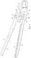
- FIG. 1is a perspective view of a surgical clamp according to one variation of the invention having a drive element situated orthogonal to the jaw portions.
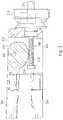
- FIG. 2is a partial cross-sectional view of a surgical clamp according to another variation of the invention having a drive element composed of a worm and worm wheel assembly.
- FIG. 3is a partial cross-sectional view of a surgical clamp according to another variation of the invention having a drive element actuated by rotation of a threaded rod through a nut.
- FIG. 4is a partial cross-sectional view of a surgical clamp according to another variation of the invention having a translationally actuated drive element.
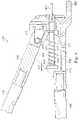
- FIG. 5is a perspective view of a clamp applier according to one variation of the invention.
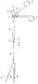
- FIG. 6is a perspective view of another clamp applier according to another variation of the invention disengaged from the clamp in FIG. 3 having a rotationally actuated drive element.
- FIGS. 7A-7Dshow a clamp applier according to another variation of the invention that slides along a wire to engage the surgical clamp of FIG. 4 and actuate its drive element.
- FIG. 7Ais a side view of the clamp and clamp applier disengaged, and the wire upon which the clamp applier slides.
- FIG. 7Bis a cross-sectional view of the clamp applier.
- FIG. 7Cis a perspective view of the clamp applier engaged with the clamp.
- FIG. 7Dis a partial cross-sectional view of the applier engaged with the clamp.
- FIGS. 8A-8Dillustrate another variation of a clamp applier for translationally actuating a drive element.
- FIG. 8Ashows a perspective view of the clamp and clamp applier disengaged along a wire.
- FIG. 8Bis a side view of the clamp and clamp applier engaged.
- FIG. 8Cis a partial cross-sectional view of the translationally actuated drive element.
- FIG. 8Dis an enlarged side view of the gearbox.
- the surgical clamp devices of this inventionmay take various forms, but as further described below, are generally designed to have first and second body portions that are pivotally connected at their proximal ends.
- the body portionsfurther include first and second jaw portions that extend from the first and second body portions, respectively.
- the body portionsare pivotally moved by rotational or translational actuation of a drive element.
- a clamp appliermay also be used to deploy the clamp if desired.
- the surgical clamps of this inventioncan be used in a variety of open, laparoscopic, or endoscopic procedures, including those requiring occlusion of hollow organs. e.g., blood vessels, ureters, bile ducts, intestines, and the like.
- the surgical clamping devicesmay be made from any biocompatible material including, but not limited to, stainless steel and any of its alloys; titanium alloys, e.g., nickel-titanium alloys; polymers. e.g., polyethylene and copolymers thereof, polyethylene terephthalate or copolymers thereof, nylon, polyurethanes, fluoropolymers, poly (vinylchloride); and combinations thereof.
- biocompatible materialincluding, but not limited to, stainless steel and any of its alloys; titanium alloys, e.g., nickel-titanium alloys; polymers. e.g., polyethylene and copolymers thereof, polyethylene terephthalate or copolymers thereof, nylon, polyurethanes, fluoropolymers, poly (vinylchloride); and combinations thereof.
- the surgical clamps of this inventiongenerally include a first body portion 14 and a second body portion 16 .
- First jaw portion 13 and second jaw portion 15are connected to, and extend from first body portion 14 and second body portion 16 , respectively.
- Body portions 14 and 16are linked together by, and pivotable about, pivot 18 .
- Pin 20 of the second body portion 16is received within slot 22 of the first body portion 14 as a guide for rotation of the body portions about the pivot 18 and to restrict the range of rotational motion about the pivot 18 .
- Jaw portions 13 , 15 and body portions 14 , 16may be sized, shaped, and/or aligned according to their intended use depending on such factors as the hollow organ or solid tissue clamped, surgeon preference, type of procedure involved, and the like.
- jaw portions 13 , 15may be straight or curved, long or short, or designed such that when directly opposed, they are transversely or vertically aligned with each other.
- jaw portions 13 , 15may also be designed to have varying degrees of flexibility and stiffness along their lengths such that they are malleable at their distal ends, and can be shaped by the surgeon just prior to clamp deployment.
- a moveable drive elementis usually positioned between, and connects, the first and second body portions.
- the drive elementmay be configured to be distal or proximal to elements such as pin 20 and slot 22 in the body portions, as shown in FIG. 1 .
- Actuation of the drive elementeither by a rotational movement or a translational movement, pivotally moves the body portions, thereby opening or closing the jaw portions.
- the drive elementsare configured to be non-back drivable. e.g., by making a fine pitch between screw threads.
- the drive elementcomprises a threaded rod 30 which is situated orthogonal to the jaw 13 , 15 and body 14 , 16 portions, and which is integrally connected to a thumbscrew 32 at approximately the midpoint of the rod 30 .
- the rod 30has a left hand thread on one side of the thumbscrew and a right hand thread on the other side.
- Rod ends 34 , 36are threaded through nuts 38 and 40 which are disposed within channels 42 and 44 that extend through body portions 14 and 16 , respectively. The nuts are mounted within the channels such that they remain aligned with the screw axis when body portions rotate about pivot 18 .
- the drive elementincludes a worm 200 and worm wheel 202 for actuating the jaw portions 204 , 206 .
- first and second body portions 208 , 210are again pivotally connected.
- the worm 200is rotatably mounted in the first body portion 208 with an axis of orientation generally parallel to the first jaw portion 204 .
- the worm 200is connected to a drive shaft 212 which extends proximally from the first body portion 208 and is coupled to an actuating knob 214 .
- the rotational axis of the actuating knob 214coincides with the drive shaft and worm axis.
- the worm wheel 202is typically integrally formed with the second body portion 210 and includes gear teeth 216 arranged in an arc about the pivot 220 that couples the first and second body portions 208 , 210 together. Gear teeth 218 on the worm 200 mesh with the gear teeth 216 of the worm wheel 202 . Rotation of the actuating knob 214 turns the drive shaft 212 , which in turn rotates the worm 200 . Rotation of the worm 200 drives the worm wheel 202 and causes movement of the second body portion 210 about the pivot 220 , thus moving the second jaw 206 toward or away from the first jaw 204 , depending on the direction of rotation of the worm 200 .
- the drive element of clamp 301includes a threaded rod 300 which is axially aligned with the first and second jaw portions 302 , 304 when they are in the clamped position.
- the rod 300is connected to a drive shaft 314 which extends proximally from the drive element.
- the drive shaft 314couples an actuating knob 312 mounted on the drive shaft 314 to the rod 300 .
- the rod 300is threaded through a nut 306 which is disposed between the first and second body portions 308 , 310 .
- the actuating knob 312is rotated, which in turn rotates threaded rod 300 .
- rod 300As rod 300 rotates, it threads through and applies an axial force on the nut 306 , which in turn applies a force onto body portions 308 , 310 .
- the direction of rotation of the actuating knob 312determines whether the jaw portions 302 , 304 open or close.
- the drive elementincludes a spring loaded ratchet slide.
- the drive element of clamp 401is axially aligned with the first and second jaw portions 400 , 402 when the jaws are in the clamped position, and is actuated by proximal movement of a ratchet slide 404 .
- a spring 406 having a distal end 405 and a proximal end 403is concentrically mounted on the ratchet slide 404 and fixedly attached to the distal end 411 of the ratchet slide 404 at its distal end 405 .
- the proximal spring end 403is free to slide along the ratchet slide 404 and engage the engaging arm 413 of the first body portion 414 when the ratchet slide 404 is moved proximally.
- One way to move the ratchet slide 404is by applying an axial force to a wire 407 attached to the proximal end 409 of the ratchet slide.
- the ratchet slide 404is also moved proximally, and the proximal end 403 of the spring 406 engages and compresses itself against engaging arm 413 , exerting a force on the first body and first jaw portion 400 , to thereby bring the first jaw portion 400 together with the second jaw portion 402 .
- the spring 406also serves to increase the clamping force resolution.
- Another spring 412may be coupled to the first body portion 414 to aid in movement of the first jaw portion 400 .
- a pawl 408keeps the jaw portions 400 , 402 closed. The pawl 408 rotates with respect to a pin 417 which is connected to the second body portion 418 .
- a generally rotational forcesufficient to counter the force supplied by a leaf spring 416 is applied to the pawl 408 to disengage it from the ratcheted portion 410 of the ratchet slide.
- the clamp appliersare generally releasably attached to one or more applier areas on the surgical clamps, e.g., the actuating knob, the drive shaft, the first body portion, and/or the second body portion, and may employ a rotational or translational movement to actuate the drive elements, but in all instances, actuate drive elements from a position distal to the first and second jaw portions.
- a clamp applierconfigured for use with a surgical clamp having a worm and worm wheel assembly ( FIG. 2 ) or a longitudinally aligned threaded rod and nut ( FIG. 3 ) is provided.
- the clamp applierincludes a rotating shaft 500 that terminates at its distal end in a drive head 502 configured for receipt of a drive element, e.g., a clamp actuating knob (element 312 in FIG. 3 ) or a drive shaft (element 212 in FIG. 2 ).
- the clamp applierWhen secured to such an element as a clamp actuating knob 214 , 312 , the clamp applier may be aligned along the rotational axis of the knob or within about 15 degrees, within about 30 degrees, or within about 45 degrees of the rotational axis of the knob.
- the proximal end of the rotating shaft 500includes a handle 504 and a handle actuating knob 506 distal to the handle 504 .
- the handle actuating knob 506is connected to the rotating shaft 500 at its proximal end such that rotation of the knob 506 rotates the shaft 500 .
- the drive head 502 of the rotating shaft 500is releasably attached to, e.g., a clamp actuating knob.
- the handle actuating knob 506is manually rotated relative to the handle, which in turn rotates the clamp actuating knob 214 , 312 to actuate the clamp jaws portions 204 , 206 , 302 , 304 as described above. Or, if the drive head 502 , the rotating shaft 500 , and the handle 504 are fixedly connected, and the actuating knob is rotatably connected to the handle 504 , the drive element may be actuated by holding the actuating knob 506 stationary and rotating as a single unit, the handle 504 , rotating shaft 500 , and drive head 502 relative to the actuating knob 506 .
- FIG. 6shows another variation of a clamp applier.
- the distal portion 602 of clamp applier 600is sized and shaped to grasp an applier area of surgical clamp 604 .
- distal portion 602is shown to be curved in FIG. 6 so that it may grasp clamp 604 along its cylindrical V-groove 606 when control arms 608 are approximated (to bring them together).
- the clamp 604may be positioned, e.g., from a location distal to the surgical field.
- a component 610 similar to the clamp applier in FIG. 5is coupled to the body 612 of the clamp applier 600 .
- the component 610includes a drive head 614 , a rotating shaft 616 , and an actuating knob 618 , typically fixedly connected.
- the component 610is coupled to the body 612 of the clamp applier 600 at least at one position along the rotating shaft 616 .
- the drive head 614releasably engages any part of a rotationally actuated drive element, e.g., the drive shaft ( 212 ) in FIG. 2 .
- Rotation of the actuating knob 618rotates the rotating shaft 616 and drive head 614 , which thereby rotates the drive element.
- the clamp appliermay also slide along a wire secured to the clamp to releasably attach itself to the clamp.
- the clamp appliers in these instancesinclude control arms that are approximated to actuate the drive element.
- the clamp applier 700includes a handle attachment 702 , a spring-loaded rear snap 704 , an outer tube 712 , an inner tube 716 , a rotator knob 718 concentrically mounted on the proximal end 708 of the outer tube, and a release disc 720 having raised areas 722 concentrically mounted on the distal end 710 of the outer tube.
- the clamp applier 700may be configured for use with clamps having drive elements as described in FIG. 4 .
- the clamp applier 700When wire fitting 706 engages the spring-loaded rear snap 704 , the clamp applier 700 is releasably attached to the clamp 401 . Pressing down on the rear snap 704 and pulling the clamp applier 700 away from the clamp 401 then disengages the applier 700 from the clamp 401 .
- a wire 407 coupled to the ratchet slide 404is placed under tension and moved proximally as the pair of control arms 714 are squeezed together. Proximal movement of the ratchet slide 404 exerts a compressive force on a spring 406 concentrically mounted on the ratchet slide 404 to exert a force on a first jaw portion 400 to bring it together with the second jaw portion 402 .
- the spring-loaded pawl 408works to prevent the jaw portions from opening as described above.
- the rotator knob 718is rotated, which in turn rotates the outer tube 712 and release disc 720 on the outer tube 712 .
- Rotation of the release disc 720thereby causes the raised areas 722 on the release disc 720 to exert a downward and rotational force on the pawl 408 to release it.
- FIGS. 8A-8DAnother variation, particularly useful with a clamp such as shown in FIG. 3 , is provided in FIGS. 8A-8D .
- the clamp applier 800is also slid along a wire 802 to releasably attach to the clamp 301 .
- the front and rear control arms 804 and 806 , respectively, of the clamp applier 800are then also squeezed together to actuate the drive element of the clamp 301 , but they are translationally approximated instead of rotationally approximated.
- FIG. 8Bafter slidably engaging the clamp 301 , the clamp jaw portions 302 , 304 are closed by translationally approximating control arms 804 , 806 .
- Gearbox 810is shown in greater detail in FIG. 8D , and generally includes a gear shaft 824 , a pinion gear 826 , a first bevel gear 828 , and a second bevel gear 830 .
- the pinion gear 826 and first bevel gear 828are connected to gear shaft 824 .
- the second bevel gear 830is connected to inner shaft 812 .
- Pinion gear 826 , first and second bevel gears 828 , 830 , and rack 808have teeth.
- the teeth of the first and second bevel gearscontact each other, and the teeth of the pinion gear 826 and rack 808 contact each other.
- Linear movement of the rack 808 to approximate the control arms 804 , 806rotates the pinion gear 826 which rotates the gear shaft 824 and first bevel gear 828 , which rotates the second bevel gear 830 and the inner shaft 812 connected to the second bevel gear 830 to actuate the drive element.
- a spring-loaded release button 822is axially fixed to the gear shaft 830 but is free to rotate about the gear shaft axis. The release button 822 may be pressed to temporarily disengage the gears in the gearbox 810 , allowing the user to slide the rear control arm 806 to a different position without actuating the jaw portions.
Landscapes
- Health & Medical Sciences (AREA)
- Surgery (AREA)
- Life Sciences & Earth Sciences (AREA)
- Heart & Thoracic Surgery (AREA)
- Nuclear Medicine, Radiotherapy & Molecular Imaging (AREA)
- Engineering & Computer Science (AREA)
- Biomedical Technology (AREA)
- Medical Informatics (AREA)
- Molecular Biology (AREA)
- Animal Behavior & Ethology (AREA)
- General Health & Medical Sciences (AREA)
- Public Health (AREA)
- Veterinary Medicine (AREA)
- Vascular Medicine (AREA)
- Reproductive Health (AREA)
- Surgical Instruments (AREA)
Abstract
Description
Claims (10)
Priority Applications (1)
| Application Number | Priority Date | Filing Date | Title |
|---|---|---|---|
| US16/885,787US11439394B2 (en) | 2002-03-26 | 2020-05-28 | Handleless clamping device |
Applications Claiming Priority (6)
| Application Number | Priority Date | Filing Date | Title |
|---|---|---|---|
| US36807402P | 2002-03-26 | 2002-03-26 | |
| US10/397,915US7588585B2 (en) | 2002-03-26 | 2003-03-25 | Handleless clamping device |
| US12/335,431US8506590B2 (en) | 2002-03-26 | 2008-12-15 | Handleless clamping device |
| US13/942,390US9782174B2 (en) | 2002-03-26 | 2013-07-15 | Handleless clamping device |
| US15/699,883US10702272B2 (en) | 2002-03-26 | 2017-09-08 | Handleless clamping device |
| US16/885,787US11439394B2 (en) | 2002-03-26 | 2020-05-28 | Handleless clamping device |
Related Parent Applications (1)
| Application Number | Title | Priority Date | Filing Date |
|---|---|---|---|
| US15/699,883ContinuationUS10702272B2 (en) | 2002-03-26 | 2017-09-08 | Handleless clamping device |
Publications (2)
| Publication Number | Publication Date |
|---|---|
| US20200352572A1 US20200352572A1 (en) | 2020-11-12 |
| US11439394B2true US11439394B2 (en) | 2022-09-13 |
Family
ID=28678210
Family Applications (7)
| Application Number | Title | Priority Date | Filing Date |
|---|---|---|---|
| US10/397,915Expired - LifetimeUS7588585B2 (en) | 2002-03-26 | 2003-03-25 | Handleless clamping device |
| US12/335,452Expired - Fee RelatedUS8361108B2 (en) | 2002-03-26 | 2008-12-15 | Handleless clamping device |
| US12/335,431Expired - Fee RelatedUS8506590B2 (en) | 2002-03-26 | 2008-12-15 | Handleless clamping device |
| US12/335,462AbandonedUS20090093842A1 (en) | 2002-03-26 | 2008-12-15 | Handleless clamping device |
| US13/942,390Expired - LifetimeUS9782174B2 (en) | 2002-03-26 | 2013-07-15 | Handleless clamping device |
| US15/699,883Expired - Fee RelatedUS10702272B2 (en) | 2002-03-26 | 2017-09-08 | Handleless clamping device |
| US16/885,787Expired - LifetimeUS11439394B2 (en) | 2002-03-26 | 2020-05-28 | Handleless clamping device |
Family Applications Before (6)
| Application Number | Title | Priority Date | Filing Date |
|---|---|---|---|
| US10/397,915Expired - LifetimeUS7588585B2 (en) | 2002-03-26 | 2003-03-25 | Handleless clamping device |
| US12/335,452Expired - Fee RelatedUS8361108B2 (en) | 2002-03-26 | 2008-12-15 | Handleless clamping device |
| US12/335,431Expired - Fee RelatedUS8506590B2 (en) | 2002-03-26 | 2008-12-15 | Handleless clamping device |
| US12/335,462AbandonedUS20090093842A1 (en) | 2002-03-26 | 2008-12-15 | Handleless clamping device |
| US13/942,390Expired - LifetimeUS9782174B2 (en) | 2002-03-26 | 2013-07-15 | Handleless clamping device |
| US15/699,883Expired - Fee RelatedUS10702272B2 (en) | 2002-03-26 | 2017-09-08 | Handleless clamping device |
Country Status (3)
| Country | Link |
|---|---|
| US (7) | US7588585B2 (en) |
| AU (1) | AU2003222060A1 (en) |
| WO (1) | WO2003082129A2 (en) |
Families Citing this family (145)
| Publication number | Priority date | Publication date | Assignee | Title |
|---|---|---|---|---|
| US6752813B2 (en) | 1999-04-09 | 2004-06-22 | Evalve, Inc. | Methods and devices for capturing and fixing leaflets in valve repair |
| AU770243B2 (en) | 1999-04-09 | 2004-02-19 | Evalve, Inc. | Methods and apparatus for cardiac valve repair |
| US10327743B2 (en) | 1999-04-09 | 2019-06-25 | Evalve, Inc. | Device and methods for endoscopic annuloplasty |
| US7226467B2 (en) | 1999-04-09 | 2007-06-05 | Evalve, Inc. | Fixation device delivery catheter, systems and methods of use |
| CA2643221A1 (en) | 2002-03-15 | 2003-09-25 | Nmt Medical, Inc. | Coupling system useful in placement of implants |
| US7588585B2 (en)* | 2002-03-26 | 2009-09-15 | Novare Surgical Systems, Inc. | Handleless clamping device |
| US7887539B2 (en) | 2003-01-24 | 2011-02-15 | Depuy Spine, Inc. | Spinal rod approximators |
| US10631871B2 (en) | 2003-05-19 | 2020-04-28 | Evalve, Inc. | Fixation devices, systems and methods for engaging tissue |
| JP2007504885A (en) | 2003-09-11 | 2007-03-08 | エヌエムティー メディカル, インコーポレイティッド | Devices, systems and methods for suturing tissue |
| US7666203B2 (en) | 2003-11-06 | 2010-02-23 | Nmt Medical, Inc. | Transseptal puncture apparatus |
| US8292910B2 (en) | 2003-11-06 | 2012-10-23 | Pressure Products Medical Supplies, Inc. | Transseptal puncture apparatus |
| JP4774048B2 (en)* | 2004-05-14 | 2011-09-14 | エヴァルヴ インコーポレイテッド | Locking mechanism of fixing device engaged with tissue and tissue engaging method |
| WO2006058221A2 (en) | 2004-11-24 | 2006-06-01 | Abdou Samy M | Devices and methods for inter-vertebral orthopedic device placement |
| US7951172B2 (en) | 2005-03-04 | 2011-05-31 | Depuy Spine Sarl | Constrained motion bone screw assembly |
| US7951175B2 (en) | 2005-03-04 | 2011-05-31 | Depuy Spine, Inc. | Instruments and methods for manipulating a vertebra |
| US7794880B2 (en)* | 2005-11-16 | 2010-09-14 | California Institute Of Technology | Fluorination of multi-layered carbon nanomaterials |
| US7371260B2 (en)* | 2005-10-26 | 2008-05-13 | Biomet Sports Medicine, Inc. | Method and instrumentation for the preparation and transplantation of osteochondral allografts |
| US20070123904A1 (en)* | 2005-10-31 | 2007-05-31 | Depuy Spine, Inc. | Distraction instrument and method for distracting an intervertebral site |
| CN100464710C (en)* | 2006-01-01 | 2009-03-04 | 杜明国 | Rectum clamp |
| EP2015681B1 (en) | 2006-05-03 | 2018-03-28 | Datascope Corp. | Tissue closure device |
| US20070118174A1 (en)* | 2006-11-16 | 2007-05-24 | Chu David Z J | Laparoscopic surgical clamp and suturing methods |
| US8568453B2 (en)* | 2007-01-29 | 2013-10-29 | Samy Abdou | Spinal stabilization systems and methods of use |
| US7655004B2 (en) | 2007-02-15 | 2010-02-02 | Ethicon Endo-Surgery, Inc. | Electroporation ablation apparatus, system, and method |
| US7899553B2 (en)* | 2007-03-28 | 2011-03-01 | Boston Scientific Neuromodulation Corporation | Lead anchor for implantable stimulation devices |
| US8075572B2 (en) | 2007-04-26 | 2011-12-13 | Ethicon Endo-Surgery, Inc. | Surgical suturing apparatus |
| US8100922B2 (en) | 2007-04-27 | 2012-01-24 | Ethicon Endo-Surgery, Inc. | Curved needle suturing tool |
| US8568410B2 (en) | 2007-08-31 | 2013-10-29 | Ethicon Endo-Surgery, Inc. | Electrical ablation surgical instruments |
| US8262655B2 (en) | 2007-11-21 | 2012-09-11 | Ethicon Endo-Surgery, Inc. | Bipolar forceps |
| US8579897B2 (en) | 2007-11-21 | 2013-11-12 | Ethicon Endo-Surgery, Inc. | Bipolar forceps |
| US8322256B2 (en)* | 2007-10-05 | 2012-12-04 | Biomet Manufacturing Corp. | System for forming a tendon-bone graft |
| US8303592B2 (en)* | 2007-10-05 | 2012-11-06 | Biomet Manufacturing Corp. | System for forming a tendon-bone graft |
| US8480657B2 (en) | 2007-10-31 | 2013-07-09 | Ethicon Endo-Surgery, Inc. | Detachable distal overtube section and methods for forming a sealable opening in the wall of an organ |
| US20090112059A1 (en) | 2007-10-31 | 2009-04-30 | Nobis Rudolph H | Apparatus and methods for closing a gastrotomy |
| USD621043S1 (en)* | 2007-11-14 | 2010-08-03 | Karl Storz Gmbh & Co. Kg | Medical instrument |
| US8262680B2 (en) | 2008-03-10 | 2012-09-11 | Ethicon Endo-Surgery, Inc. | Anastomotic device |
| US8709015B2 (en) | 2008-03-10 | 2014-04-29 | DePuy Synthes Products, LLC | Bilateral vertebral body derotation system |
| US8608746B2 (en) | 2008-03-10 | 2013-12-17 | DePuy Synthes Products, LLC | Derotation instrument with reduction functionality |
| US8771260B2 (en) | 2008-05-30 | 2014-07-08 | Ethicon Endo-Surgery, Inc. | Actuating and articulating surgical device |
| US8317806B2 (en) | 2008-05-30 | 2012-11-27 | Ethicon Endo-Surgery, Inc. | Endoscopic suturing tension controlling and indication devices |
| US8679003B2 (en) | 2008-05-30 | 2014-03-25 | Ethicon Endo-Surgery, Inc. | Surgical device and endoscope including same |
| US8114072B2 (en) | 2008-05-30 | 2012-02-14 | Ethicon Endo-Surgery, Inc. | Electrical ablation device |
| US8070759B2 (en) | 2008-05-30 | 2011-12-06 | Ethicon Endo-Surgery, Inc. | Surgical fastening device |
| US8652150B2 (en) | 2008-05-30 | 2014-02-18 | Ethicon Endo-Surgery, Inc. | Multifunction surgical device |
| US8906035B2 (en) | 2008-06-04 | 2014-12-09 | Ethicon Endo-Surgery, Inc. | Endoscopic drop off bag |
| US8403926B2 (en) | 2008-06-05 | 2013-03-26 | Ethicon Endo-Surgery, Inc. | Manually articulating devices |
| US10973556B2 (en) | 2008-06-17 | 2021-04-13 | DePuy Synthes Products, Inc. | Adjustable implant assembly |
| US8361112B2 (en) | 2008-06-27 | 2013-01-29 | Ethicon Endo-Surgery, Inc. | Surgical suture arrangement |
| US8262563B2 (en) | 2008-07-14 | 2012-09-11 | Ethicon Endo-Surgery, Inc. | Endoscopic translumenal articulatable steerable overtube |
| US8888792B2 (en) | 2008-07-14 | 2014-11-18 | Ethicon Endo-Surgery, Inc. | Tissue apposition clip application devices and methods |
| US8211125B2 (en) | 2008-08-15 | 2012-07-03 | Ethicon Endo-Surgery, Inc. | Sterile appliance delivery device for endoscopic procedures |
| US8529563B2 (en) | 2008-08-25 | 2013-09-10 | Ethicon Endo-Surgery, Inc. | Electrical ablation devices |
| US8241204B2 (en) | 2008-08-29 | 2012-08-14 | Ethicon Endo-Surgery, Inc. | Articulating end cap |
| US8480689B2 (en) | 2008-09-02 | 2013-07-09 | Ethicon Endo-Surgery, Inc. | Suturing device |
| US8409200B2 (en) | 2008-09-03 | 2013-04-02 | Ethicon Endo-Surgery, Inc. | Surgical grasping device |
| US8114119B2 (en) | 2008-09-09 | 2012-02-14 | Ethicon Endo-Surgery, Inc. | Surgical grasping device |
| US8337394B2 (en) | 2008-10-01 | 2012-12-25 | Ethicon Endo-Surgery, Inc. | Overtube with expandable tip |
| US8157834B2 (en) | 2008-11-25 | 2012-04-17 | Ethicon Endo-Surgery, Inc. | Rotational coupling device for surgical instrument with flexible actuators |
| US8172772B2 (en) | 2008-12-11 | 2012-05-08 | Ethicon Endo-Surgery, Inc. | Specimen retrieval device |
| US8361066B2 (en) | 2009-01-12 | 2013-01-29 | Ethicon Endo-Surgery, Inc. | Electrical ablation devices |
| US8828031B2 (en) | 2009-01-12 | 2014-09-09 | Ethicon Endo-Surgery, Inc. | Apparatus for forming an anastomosis |
| US8252057B2 (en) | 2009-01-30 | 2012-08-28 | Ethicon Endo-Surgery, Inc. | Surgical access device |
| US9226772B2 (en) | 2009-01-30 | 2016-01-05 | Ethicon Endo-Surgery, Inc. | Surgical device |
| US8037591B2 (en) | 2009-02-02 | 2011-10-18 | Ethicon Endo-Surgery, Inc. | Surgical scissors |
| WO2011037969A1 (en) | 2009-09-23 | 2011-03-31 | Depuy Spine, Inc. | Methods and devices for manipulating a vertebra |
| US20110098704A1 (en) | 2009-10-28 | 2011-04-28 | Ethicon Endo-Surgery, Inc. | Electrical ablation devices |
| US8608652B2 (en) | 2009-11-05 | 2013-12-17 | Ethicon Endo-Surgery, Inc. | Vaginal entry surgical devices, kit, system, and method |
| PL2324781T3 (en)* | 2009-11-20 | 2013-06-28 | Facet Link Inc | Surgical guide instrument for working on facet joint extensions in spines |
| US8764806B2 (en) | 2009-12-07 | 2014-07-01 | Samy Abdou | Devices and methods for minimally invasive spinal stabilization and instrumentation |
| US8496574B2 (en) | 2009-12-17 | 2013-07-30 | Ethicon Endo-Surgery, Inc. | Selectively positionable camera for surgical guide tube assembly |
| EP2335609B1 (en)* | 2009-12-17 | 2012-04-18 | CARDIOMEDICAL GmbH | Surgical instrument |
| US8353487B2 (en) | 2009-12-17 | 2013-01-15 | Ethicon Endo-Surgery, Inc. | User interface support devices for endoscopic surgical instruments |
| US9028483B2 (en) | 2009-12-18 | 2015-05-12 | Ethicon Endo-Surgery, Inc. | Surgical instrument comprising an electrode |
| US8506564B2 (en) | 2009-12-18 | 2013-08-13 | Ethicon Endo-Surgery, Inc. | Surgical instrument comprising an electrode |
| US9005198B2 (en) | 2010-01-29 | 2015-04-14 | Ethicon Endo-Surgery, Inc. | Surgical instrument comprising an electrode |
| JP6069207B2 (en)* | 2010-10-15 | 2017-02-01 | サージクランプ プロプライエタリー リミテッド | Surgical clamping device and instrument for use therewith |
| US10092291B2 (en) | 2011-01-25 | 2018-10-09 | Ethicon Endo-Surgery, Inc. | Surgical instrument with selectively rigidizable features |
| TWI503098B (en)* | 2011-01-31 | 2015-10-11 | Surgical clamps | |
| US9314620B2 (en) | 2011-02-28 | 2016-04-19 | Ethicon Endo-Surgery, Inc. | Electrical ablation devices and methods |
| US9254169B2 (en) | 2011-02-28 | 2016-02-09 | Ethicon Endo-Surgery, Inc. | Electrical ablation devices and methods |
| US9233241B2 (en) | 2011-02-28 | 2016-01-12 | Ethicon Endo-Surgery, Inc. | Electrical ablation devices and methods |
| US9049987B2 (en) | 2011-03-17 | 2015-06-09 | Ethicon Endo-Surgery, Inc. | Hand held surgical device for manipulating an internal magnet assembly within a patient |
| US8828034B2 (en)* | 2011-04-29 | 2014-09-09 | Lifeline Scientific, Inc. | Cannula |
| US8945177B2 (en) | 2011-09-13 | 2015-02-03 | Abbott Cardiovascular Systems Inc. | Gripper pusher mechanism for tissue apposition systems |
| US8845728B1 (en) | 2011-09-23 | 2014-09-30 | Samy Abdou | Spinal fixation devices and methods of use |
| US9044258B2 (en)* | 2011-12-27 | 2015-06-02 | Specialty Surgical Instrumentation Inc. | Instrument with removable tip |
| US8986199B2 (en) | 2012-02-17 | 2015-03-24 | Ethicon Endo-Surgery, Inc. | Apparatus and methods for cleaning the lens of an endoscope |
| US20130226240A1 (en) | 2012-02-22 | 2013-08-29 | Samy Abdou | Spinous process fixation devices and methods of use |
| US9821145B2 (en) | 2012-03-23 | 2017-11-21 | Pressure Products Medical Supplies Inc. | Transseptal puncture apparatus and method for using the same |
| US9358008B2 (en)* | 2012-04-30 | 2016-06-07 | Zsx Medical, Llc | Surgical device |
| US9427255B2 (en) | 2012-05-14 | 2016-08-30 | Ethicon Endo-Surgery, Inc. | Apparatus for introducing a steerable camera assembly into a patient |
| US9078662B2 (en) | 2012-07-03 | 2015-07-14 | Ethicon Endo-Surgery, Inc. | Endoscopic cap electrode and method for using the same |
| US8814889B2 (en)* | 2012-07-10 | 2014-08-26 | Lifeline Scientific, Inc. | Cannula with floating clamp member |
| US9259562B2 (en) | 2012-07-10 | 2016-02-16 | Lifeline Scientific, Inc. | Cannula |
| US9545290B2 (en) | 2012-07-30 | 2017-01-17 | Ethicon Endo-Surgery, Inc. | Needle probe guide |
| US10314649B2 (en) | 2012-08-02 | 2019-06-11 | Ethicon Endo-Surgery, Inc. | Flexible expandable electrode and method of intraluminal delivery of pulsed power |
| US9572623B2 (en) | 2012-08-02 | 2017-02-21 | Ethicon Endo-Surgery, Inc. | Reusable electrode and disposable sheath |
| US9277957B2 (en) | 2012-08-15 | 2016-03-08 | Ethicon Endo-Surgery, Inc. | Electrosurgical devices and methods |
| US9198767B2 (en) | 2012-08-28 | 2015-12-01 | Samy Abdou | Devices and methods for spinal stabilization and instrumentation |
| US9320617B2 (en) | 2012-10-22 | 2016-04-26 | Cogent Spine, LLC | Devices and methods for spinal stabilization and instrumentation |
| USD713959S1 (en)* | 2013-02-01 | 2014-09-23 | Cardiomedical Gmbh | Surgical clamp |
| US10098527B2 (en) | 2013-02-27 | 2018-10-16 | Ethidcon Endo-Surgery, Inc. | System for performing a minimally invasive surgical procedure |
| USD713526S1 (en)* | 2013-07-26 | 2014-09-16 | Cardiomedical Gmbh | Surgical clamp |
| WO2015077356A1 (en) | 2013-11-19 | 2015-05-28 | Wheeler William K | Fastener applicator with interlock |
| US10076341B2 (en)* | 2014-03-10 | 2018-09-18 | Neuroenterprises, Llc | Variable angle surgical instrument and method of use |
| US10390943B2 (en) | 2014-03-17 | 2019-08-27 | Evalve, Inc. | Double orifice device for transcatheter mitral valve replacement |
| US9901335B2 (en)* | 2014-07-10 | 2018-02-27 | Maxwell Choongwon Park | Method and apparatus for securing soft tissue to bone |
| US10188392B2 (en) | 2014-12-19 | 2019-01-29 | Abbott Cardiovascular Systems, Inc. | Grasping for tissue repair |
| US10524912B2 (en) | 2015-04-02 | 2020-01-07 | Abbott Cardiovascular Systems, Inc. | Tissue fixation devices and methods |
| US10376673B2 (en) | 2015-06-19 | 2019-08-13 | Evalve, Inc. | Catheter guiding system and methods |
| US10238494B2 (en) | 2015-06-29 | 2019-03-26 | Evalve, Inc. | Self-aligning radiopaque ring |
| US10667815B2 (en) | 2015-07-21 | 2020-06-02 | Evalve, Inc. | Tissue grasping devices and related methods |
| US10413408B2 (en) | 2015-08-06 | 2019-09-17 | Evalve, Inc. | Delivery catheter systems, methods, and devices |
| US10238495B2 (en) | 2015-10-09 | 2019-03-26 | Evalve, Inc. | Delivery catheter handle and methods of use |
| US10857003B1 (en) | 2015-10-14 | 2020-12-08 | Samy Abdou | Devices and methods for vertebral stabilization |
| US10543004B2 (en)* | 2015-12-23 | 2020-01-28 | Osteomed Llc | Bone centering drill guide |
| US10736632B2 (en) | 2016-07-06 | 2020-08-11 | Evalve, Inc. | Methods and devices for valve clip excision |
| DE102016116624A1 (en)* | 2016-09-06 | 2018-03-22 | Karl Leibinger Medizintechnik Gmbh & Co. Kg | Medical instrument with cleaning gap in the closure area |
| US11071564B2 (en) | 2016-10-05 | 2021-07-27 | Evalve, Inc. | Cardiac valve cutting device |
| US10744000B1 (en) | 2016-10-25 | 2020-08-18 | Samy Abdou | Devices and methods for vertebral bone realignment |
| US10973648B1 (en) | 2016-10-25 | 2021-04-13 | Samy Abdou | Devices and methods for vertebral bone realignment |
| US10363138B2 (en) | 2016-11-09 | 2019-07-30 | Evalve, Inc. | Devices for adjusting the curvature of cardiac valve structures |
| US10398553B2 (en) | 2016-11-11 | 2019-09-03 | Evalve, Inc. | Opposing disk device for grasping cardiac valve tissue |
| US10426616B2 (en) | 2016-11-17 | 2019-10-01 | Evalve, Inc. | Cardiac implant delivery system |
| US10779837B2 (en) | 2016-12-08 | 2020-09-22 | Evalve, Inc. | Adjustable arm device for grasping tissues |
| US10314586B2 (en) | 2016-12-13 | 2019-06-11 | Evalve, Inc. | Rotatable device and method for fixing tricuspid valve tissue |
| CN106913368B (en)* | 2017-04-21 | 2023-09-26 | 胡金玺 | Minimally invasive difficult-to-restore cis-tuberosity fracture reduction forceps |
| WO2018209313A1 (en) | 2017-05-12 | 2018-11-15 | Evalve, Inc. | Long arm valve repair clip |
| AU2018275008B2 (en)* | 2017-07-18 | 2019-04-11 | Vascular Devices Pty Ltd | Surgical clamp |
| JP7348199B2 (en) | 2018-03-28 | 2023-09-20 | データスコープ コーポレイション | Device for atrial appendage exclusion |
| USD884170S1 (en)* | 2018-04-03 | 2020-05-12 | Karl Storz Se & Co. Kg | Clamp for laparoscopic sleeve gastrectomy |
| USD884891S1 (en)* | 2018-04-03 | 2020-05-19 | Karl Storz Se & Co. Kg | Clamp for laparoscopic sleeve gastrectomy |
| US11179248B2 (en) | 2018-10-02 | 2021-11-23 | Samy Abdou | Devices and methods for spinal implantation |
| JP7543391B2 (en) | 2019-07-15 | 2024-09-02 | エバルブ,インコーポレイティド | Method of Actuating Individual Proximal Elements |
| US11877833B2 (en)* | 2019-07-26 | 2024-01-23 | Covidien Lp | Systems and methods for monitoring blood pressure with a powered linear drive |
| CN111249064B (en)* | 2020-03-12 | 2021-08-31 | 江苏康视佳医疗器械有限公司 | Straight retinal forceps with sawteeth |
| CN111449793B (en)* | 2020-04-05 | 2024-12-06 | 中国人民解放军总医院 | A continuously controllable vascular constrictor |
| US12171486B2 (en) | 2020-05-06 | 2024-12-24 | Evalve, Inc. | Devices and methods for clip separation |
| US12171485B2 (en) | 2020-05-06 | 2024-12-24 | Evalve, Inc. | Systems and methods for leaflet cutting using a hook catheter |
| US12048448B2 (en) | 2020-05-06 | 2024-07-30 | Evalve, Inc. | Leaflet grasping and cutting device |
| US12178444B2 (en) | 2020-05-06 | 2024-12-31 | Evalve, Inc. | Clip removal systems and methods |
| US12414811B2 (en) | 2020-05-06 | 2025-09-16 | Evalve, Inc. | Devices and methods for leaflet cutting |
| EP4419018A4 (en)* | 2021-10-20 | 2025-02-19 | USB Medical, Ltd. | IMPROVED SURGICAL STAPLER WITH EMERGENCY RELEASE |
| CN115867210A (en)* | 2022-03-21 | 2023-03-28 | 宁波新跃医疗科技股份有限公司 | Plug-in tissue clamping device and clamping piece thereof |
| WO2022257536A1 (en)* | 2022-03-21 | 2022-12-15 | 宁波新跃医疗科技股份有限公司 | Insertable tissue clamping apparatus and gripping piece thereof |
| CN115916073A (en)* | 2022-03-21 | 2023-04-04 | 宁波新跃医疗科技股份有限公司 | Plug-in tissue clamping device and clamping piece thereof |
Citations (56)
| Publication number | Priority date | Publication date | Assignee | Title |
|---|---|---|---|---|
| US2400142A (en) | 1944-03-17 | 1946-05-14 | Tinnerman Products Inc | Fastening device |
| US2549229A (en) | 1944-09-11 | 1951-04-17 | Ottoson Oscar | Holder for double-edged razor blades |
| US2592484A (en) | 1946-06-15 | 1952-04-08 | Moreton A Smith | Power-driven tweezer |
| CA618821A (en) | 1961-04-25 | A. Reindorf Carl | Surgical clamp | |
| US3136040A (en) | 1961-04-21 | 1964-06-09 | Navigation Computor Corp | Insertion and withdrawal tool |
| US3503397A (en)* | 1967-09-21 | 1970-03-31 | American Hospital Supply Corp | Atraumatic surgical clamp |
| US3602989A (en) | 1969-10-01 | 1971-09-07 | Marnie C Averitt | Stored energy shear device |
| US3664621A (en) | 1970-08-28 | 1972-05-23 | Hilbert J Savoie Jr | Underwater pipeline-riser clamps for use on oil and gas pipelines |
| US3797498A (en) | 1972-06-09 | 1974-03-19 | Kerr Instr Ltd | Pivotal surgical clip |
| US4009899A (en) | 1975-10-16 | 1977-03-01 | Fluoroware, Inc. | Wafer tongs |
| US4248233A (en) | 1974-11-19 | 1981-02-03 | Zeppelin Dieter Von | Forceps |
| US4424811A (en) | 1979-05-07 | 1984-01-10 | Groot Gerrit Sjoerd | Pinching device for surgical purposes |
| US4443196A (en) | 1982-09-20 | 1984-04-17 | Miguel Rico | Tooth root extractor |
| SU1123671A1 (en) | 1982-12-02 | 1984-11-15 | Днепропетровский Ордена Трудового Красного Знамени Медицинский Институт | Forceps |
| NL8301618A (en) | 1983-05-06 | 1984-12-03 | Solleveld Hendrik Adolf | Clamp for combating migraine - has bolt actuated adjustable clamp jaws pressing on ear lobes |
| GB2191439A (en) | 1986-05-30 | 1987-12-16 | Detlef Uthoff | Forceps particularly for use in implanting eye lenses |
| EP0297771A1 (en) | 1987-06-24 | 1989-01-04 | United States Surgical Corporation | Vascular clamp assembly |
| US4806770A (en) | 1987-02-02 | 1989-02-21 | William M. Hylton | Germicidal toothbrush holder |
| WO1989010095A1 (en) | 1988-04-30 | 1989-11-02 | Mecron Medizinische Produkte Gmbh | Holding device for orthopaedic purposes |
| FR2630904A2 (en) | 1988-05-05 | 1989-11-10 | Chastenet De Castaing Guillaum | Twinning mechanism for dissection forceps |
| US4932955A (en) | 1984-06-29 | 1990-06-12 | Baxter International Inc. | Clip |
| US4957500A (en) | 1988-10-27 | 1990-09-18 | Montefiore Hospital Association Of Western Pennsylvania | Normally closed clamp |
| US4976721A (en) | 1988-12-14 | 1990-12-11 | The Research Foundation Of State University Of New York | Surgical clamping device |
| US5103839A (en) | 1987-06-24 | 1992-04-14 | United States Surgical Corporation | Method of using a vascular clamp assembly |
| WO1992011813A1 (en) | 1991-01-07 | 1992-07-23 | Heidmueller Harald | Clip applicator |
| US5147378A (en) | 1991-03-05 | 1992-09-15 | Harold Markham | Grapsing forceps |
| US5176700A (en) | 1991-01-22 | 1993-01-05 | Pod, Inc. | Laparoscopic sponger-dissector forceps |
| US5250074A (en) | 1992-07-14 | 1993-10-05 | Wilk Peter J | Surgical instrument assembly and associated technique |
| US5275615A (en) | 1992-09-11 | 1994-01-04 | Anthony Rose | Medical instrument having gripping jaws |
| US5308357A (en) | 1992-08-21 | 1994-05-03 | Microsurge, Inc. | Handle mechanism for manual instruments |
| USD346862S (en)* | 1991-03-07 | 1994-05-10 | Tibor Koros | Reverse action surgical needle holder |
| US5385471A (en) | 1993-01-05 | 1995-01-31 | Chuen; Ng T. | Cerec inlay holder and inserter |
| US5478350A (en) | 1994-07-14 | 1995-12-26 | Symbiosis Corporation | Rack and pinion actuator handle for endoscopic instruments |
| US5582617A (en) | 1993-07-21 | 1996-12-10 | Charles H. Klieman | Surgical instrument for endoscopic and general surgery |
| US5611813A (en) | 1992-04-15 | 1997-03-18 | Microsurge, Inc. | Surgical instrument |
| US5618306A (en) | 1994-02-14 | 1997-04-08 | Heartport, Inc. | Endoscopic microsurgical instruments and methods |
| WO1997020506A1 (en) | 1995-12-04 | 1997-06-12 | Heartport, Inc. | Clamp assembly and method of use |
| US5645552A (en) | 1995-01-11 | 1997-07-08 | United States Surgical Corporation | Surgical apparatus for suturing body tissue |
| US5720751A (en) | 1996-11-27 | 1998-02-24 | Jackson; Roger P. | Tools for use in seating spinal rods in open ended implants |
| US5776147A (en) | 1993-10-20 | 1998-07-07 | Applied Medical Resources Corporation | Laparoscopic surgical clamp |
| US5827263A (en) | 1994-07-21 | 1998-10-27 | Genzyme Corporation | Surgical instrument handle |
| DE19719090A1 (en) | 1997-05-01 | 1998-11-05 | Ulrich Dipl Ing Merkle | Minimal invasive surgical instrument |
| US5851214A (en) | 1994-10-07 | 1998-12-22 | United States Surgical Corporation | Surgical instrument useful for endoscopic procedures |
| US5921996A (en) | 1997-05-02 | 1999-07-13 | Cardio Thoracic Systems, Inc. | Surgical clamp applier/remover and detachable clamp |
| US5944736A (en) | 1996-02-20 | 1999-08-31 | Cardiothoracic Systems, Inc. | Access platform for internal mammary dissection |
| US5980519A (en) | 1996-07-30 | 1999-11-09 | Symbiosis Corporation | Electrocautery probe with variable morphology electrode |
| US5984934A (en) | 1997-10-10 | 1999-11-16 | Applied Medical Resources Corporation | Low-profile surgical clip |
| US6099539A (en) | 1998-07-27 | 2000-08-08 | Thomas J. Fogarty | Surgical clamp pad with interdigitating teeth |
| US6117146A (en) | 1999-06-14 | 2000-09-12 | The University Of New Mexico | Vasculopath |
| US6210419B1 (en) | 1998-12-18 | 2001-04-03 | Aesculap Ag & Co. Kg | Surgical clip |
| US6228104B1 (en) | 1999-06-18 | 2001-05-08 | Novare Surgical Systems, Inc. | Surgical clamp having replaceable pad |
| US6273902B1 (en) | 1999-06-18 | 2001-08-14 | Novare Surgical Systems, Inc. | Surgical clamp having replaceable pad |
| US20010034536A1 (en) | 1997-09-25 | 2001-10-25 | Looper Anthony M. | Surgical device with malleable shaft |
| US6387112B1 (en) | 1999-06-18 | 2002-05-14 | Novare Surgical Systems, Inc. | Surgical clamp having replaceable pad |
| US6610074B2 (en) | 2000-02-10 | 2003-08-26 | Albert N. Santilli | Aorta cross clamp assembly |
| WO2003082129A2 (en) | 2002-03-26 | 2003-10-09 | Novare Surgical Systems, Inc. | Handleless clamping device |
Family Cites Families (1)
| Publication number | Priority date | Publication date | Assignee | Title |
|---|---|---|---|---|
| US6228004B1 (en)* | 1998-06-26 | 2001-05-08 | Bedside Rehabilitation Technology, Inc. | Versatile physical therapy apparatus |
- 2003
- 2003-03-25USUS10/397,915patent/US7588585B2/ennot_activeExpired - Lifetime
- 2003-03-26AUAU2003222060Apatent/AU2003222060A1/ennot_activeAbandoned
- 2003-03-26WOPCT/US2003/009035patent/WO2003082129A2/ennot_activeApplication Discontinuation
- 2008
- 2008-12-15USUS12/335,452patent/US8361108B2/ennot_activeExpired - Fee Related
- 2008-12-15USUS12/335,431patent/US8506590B2/ennot_activeExpired - Fee Related
- 2008-12-15USUS12/335,462patent/US20090093842A1/ennot_activeAbandoned
- 2013
- 2013-07-15USUS13/942,390patent/US9782174B2/ennot_activeExpired - Lifetime
- 2017
- 2017-09-08USUS15/699,883patent/US10702272B2/ennot_activeExpired - Fee Related
- 2020
- 2020-05-28USUS16/885,787patent/US11439394B2/ennot_activeExpired - Lifetime
Patent Citations (64)
| Publication number | Priority date | Publication date | Assignee | Title |
|---|---|---|---|---|
| CA618821A (en) | 1961-04-25 | A. Reindorf Carl | Surgical clamp | |
| US2400142A (en) | 1944-03-17 | 1946-05-14 | Tinnerman Products Inc | Fastening device |
| US2549229A (en) | 1944-09-11 | 1951-04-17 | Ottoson Oscar | Holder for double-edged razor blades |
| US2592484A (en) | 1946-06-15 | 1952-04-08 | Moreton A Smith | Power-driven tweezer |
| US3136040A (en) | 1961-04-21 | 1964-06-09 | Navigation Computor Corp | Insertion and withdrawal tool |
| US3503397A (en)* | 1967-09-21 | 1970-03-31 | American Hospital Supply Corp | Atraumatic surgical clamp |
| US3602989A (en) | 1969-10-01 | 1971-09-07 | Marnie C Averitt | Stored energy shear device |
| US3664621A (en) | 1970-08-28 | 1972-05-23 | Hilbert J Savoie Jr | Underwater pipeline-riser clamps for use on oil and gas pipelines |
| US3797498A (en) | 1972-06-09 | 1974-03-19 | Kerr Instr Ltd | Pivotal surgical clip |
| US4248233A (en) | 1974-11-19 | 1981-02-03 | Zeppelin Dieter Von | Forceps |
| US4009899A (en) | 1975-10-16 | 1977-03-01 | Fluoroware, Inc. | Wafer tongs |
| US4424811A (en) | 1979-05-07 | 1984-01-10 | Groot Gerrit Sjoerd | Pinching device for surgical purposes |
| US4443196A (en) | 1982-09-20 | 1984-04-17 | Miguel Rico | Tooth root extractor |
| SU1123671A1 (en) | 1982-12-02 | 1984-11-15 | Днепропетровский Ордена Трудового Красного Знамени Медицинский Институт | Forceps |
| NL8301618A (en) | 1983-05-06 | 1984-12-03 | Solleveld Hendrik Adolf | Clamp for combating migraine - has bolt actuated adjustable clamp jaws pressing on ear lobes |
| US4932955A (en) | 1984-06-29 | 1990-06-12 | Baxter International Inc. | Clip |
| GB2191439A (en) | 1986-05-30 | 1987-12-16 | Detlef Uthoff | Forceps particularly for use in implanting eye lenses |
| US4806770A (en) | 1987-02-02 | 1989-02-21 | William M. Hylton | Germicidal toothbrush holder |
| EP0297771A1 (en) | 1987-06-24 | 1989-01-04 | United States Surgical Corporation | Vascular clamp assembly |
| US5103839A (en) | 1987-06-24 | 1992-04-14 | United States Surgical Corporation | Method of using a vascular clamp assembly |
| WO1989010095A1 (en) | 1988-04-30 | 1989-11-02 | Mecron Medizinische Produkte Gmbh | Holding device for orthopaedic purposes |
| FR2630904A2 (en) | 1988-05-05 | 1989-11-10 | Chastenet De Castaing Guillaum | Twinning mechanism for dissection forceps |
| US4957500A (en) | 1988-10-27 | 1990-09-18 | Montefiore Hospital Association Of Western Pennsylvania | Normally closed clamp |
| US4976721A (en) | 1988-12-14 | 1990-12-11 | The Research Foundation Of State University Of New York | Surgical clamping device |
| WO1992011813A1 (en) | 1991-01-07 | 1992-07-23 | Heidmueller Harald | Clip applicator |
| US5176700A (en) | 1991-01-22 | 1993-01-05 | Pod, Inc. | Laparoscopic sponger-dissector forceps |
| US5147378A (en) | 1991-03-05 | 1992-09-15 | Harold Markham | Grapsing forceps |
| USD346862S (en)* | 1991-03-07 | 1994-05-10 | Tibor Koros | Reverse action surgical needle holder |
| US5611813A (en) | 1992-04-15 | 1997-03-18 | Microsurge, Inc. | Surgical instrument |
| US5250074A (en) | 1992-07-14 | 1993-10-05 | Wilk Peter J | Surgical instrument assembly and associated technique |
| US5308357A (en) | 1992-08-21 | 1994-05-03 | Microsurge, Inc. | Handle mechanism for manual instruments |
| US5275615A (en) | 1992-09-11 | 1994-01-04 | Anthony Rose | Medical instrument having gripping jaws |
| US5385471A (en) | 1993-01-05 | 1995-01-31 | Chuen; Ng T. | Cerec inlay holder and inserter |
| US5582617A (en) | 1993-07-21 | 1996-12-10 | Charles H. Klieman | Surgical instrument for endoscopic and general surgery |
| US5776147A (en) | 1993-10-20 | 1998-07-07 | Applied Medical Resources Corporation | Laparoscopic surgical clamp |
| US5618306A (en) | 1994-02-14 | 1997-04-08 | Heartport, Inc. | Endoscopic microsurgical instruments and methods |
| US5810877A (en) | 1994-02-14 | 1998-09-22 | Heartport, Inc. | Endoscopic microsurgical instruments and methods |
| US5478350A (en) | 1994-07-14 | 1995-12-26 | Symbiosis Corporation | Rack and pinion actuator handle for endoscopic instruments |
| US5827263A (en) | 1994-07-21 | 1998-10-27 | Genzyme Corporation | Surgical instrument handle |
| US5851214A (en) | 1994-10-07 | 1998-12-22 | United States Surgical Corporation | Surgical instrument useful for endoscopic procedures |
| US5645552A (en) | 1995-01-11 | 1997-07-08 | United States Surgical Corporation | Surgical apparatus for suturing body tissue |
| WO1997020506A1 (en) | 1995-12-04 | 1997-06-12 | Heartport, Inc. | Clamp assembly and method of use |
| US5944736A (en) | 1996-02-20 | 1999-08-31 | Cardiothoracic Systems, Inc. | Access platform for internal mammary dissection |
| US5980519A (en) | 1996-07-30 | 1999-11-09 | Symbiosis Corporation | Electrocautery probe with variable morphology electrode |
| US5720751A (en) | 1996-11-27 | 1998-02-24 | Jackson; Roger P. | Tools for use in seating spinal rods in open ended implants |
| DE19719090A1 (en) | 1997-05-01 | 1998-11-05 | Ulrich Dipl Ing Merkle | Minimal invasive surgical instrument |
| US5921996A (en) | 1997-05-02 | 1999-07-13 | Cardio Thoracic Systems, Inc. | Surgical clamp applier/remover and detachable clamp |
| US20010034536A1 (en) | 1997-09-25 | 2001-10-25 | Looper Anthony M. | Surgical device with malleable shaft |
| US5984934A (en) | 1997-10-10 | 1999-11-16 | Applied Medical Resources Corporation | Low-profile surgical clip |
| US6099539A (en) | 1998-07-27 | 2000-08-08 | Thomas J. Fogarty | Surgical clamp pad with interdigitating teeth |
| US6206896B1 (en) | 1998-07-27 | 2001-03-27 | Thomas J. Fogarty | Surgical clamp pad with interdigitating teeth |
| US6210419B1 (en) | 1998-12-18 | 2001-04-03 | Aesculap Ag & Co. Kg | Surgical clip |
| US6117146A (en) | 1999-06-14 | 2000-09-12 | The University Of New Mexico | Vasculopath |
| US6228104B1 (en) | 1999-06-18 | 2001-05-08 | Novare Surgical Systems, Inc. | Surgical clamp having replaceable pad |
| US6273902B1 (en) | 1999-06-18 | 2001-08-14 | Novare Surgical Systems, Inc. | Surgical clamp having replaceable pad |
| US6387112B1 (en) | 1999-06-18 | 2002-05-14 | Novare Surgical Systems, Inc. | Surgical clamp having replaceable pad |
| US6610074B2 (en) | 2000-02-10 | 2003-08-26 | Albert N. Santilli | Aorta cross clamp assembly |
| WO2003082129A2 (en) | 2002-03-26 | 2003-10-09 | Novare Surgical Systems, Inc. | Handleless clamping device |
| US20090093842A1 (en) | 2002-03-26 | 2009-04-09 | Novare Surgical Systems, Inc. | Handleless clamping device |
| US7588585B2 (en) | 2002-03-26 | 2009-09-15 | Novare Surgical Systems, Inc. | Handleless clamping device |
| US8361108B2 (en) | 2002-03-26 | 2013-01-29 | Intuitive Surgical Operations, Inc. | Handleless clamping device |
| US8506590B2 (en) | 2002-03-26 | 2013-08-13 | Intuitive Surgical Operations, Inc. | Handleless clamping device |
| US9782174B2 (en) | 2002-03-26 | 2017-10-10 | Intuitive Surgical Operations, Inc. | Handleless clamping device |
| US20170367703A1 (en) | 2002-03-26 | 2017-12-28 | Intuitive Surgical Operations, Inc. | Handleless Clamping Device |
Non-Patent Citations (2)
| Title |
|---|
| International Search Report for Application No. PCT/US03/09035, dated Apr. 23, 2004, 3 pages. |
| Vertut, Jean and Phillipe Coiffet, Robot Technology: Teleoperation and Robotics Evolution and Development, English translation, Prentice-Hall, Inc., Inglewood Cliffs, NJ, USA 1986, vol. 3A, 332 pages. |
Also Published As
| Publication number | Publication date |
|---|---|
| AU2003222060A8 (en) | 2003-10-13 |
| US10702272B2 (en) | 2020-07-07 |
| US20200352572A1 (en) | 2020-11-12 |
| US20090093842A1 (en) | 2009-04-09 |
| US8506590B2 (en) | 2013-08-13 |
| US7588585B2 (en) | 2009-09-15 |
| US20170367703A1 (en) | 2017-12-28 |
| US20090093828A1 (en) | 2009-04-09 |
| US9782174B2 (en) | 2017-10-10 |
| WO2003082129A3 (en) | 2004-06-10 |
| US20090093841A1 (en) | 2009-04-09 |
| US8361108B2 (en) | 2013-01-29 |
| US20140005697A1 (en) | 2014-01-02 |
| US20030212435A1 (en) | 2003-11-13 |
| AU2003222060A1 (en) | 2003-10-13 |
| WO2003082129A2 (en) | 2003-10-09 |
Similar Documents
| Publication | Publication Date | Title |
|---|---|---|
| US11439394B2 (en) | Handleless clamping device | |
| CA2482198C (en) | Surgical device with malleable shaft | |
| AU2007216621B2 (en) | Rotating knob locking mechanism for surgical stapling device | |
| AU2008205430B2 (en) | Articulating joint for surgical instruments | |
| US20190046203A1 (en) | Geared actuation mechanism and surgical clip applier including the same | |
| CA2387141C (en) | Flexible biopsy jaw assembly | |
| US8636757B2 (en) | Bendable shaft assembly for a clamp | |
| US7108703B2 (en) | Clamp having bendable shaft | |
| US20020165565A1 (en) | Clamp having bendable shaft | |
| AU2013206659B2 (en) | Rotating knob locking mechanism for surgical stapling device |
Legal Events
| Date | Code | Title | Description |
|---|---|---|---|
| AS | Assignment | Owner name:INTUITIVE SURGICAL OPERATIONS, INC., CALIFORNIA Free format text:ASSIGNMENT OF ASSIGNORS INTEREST;ASSIGNOR:NOVARE SURGICAL SYSTEMS, INC.;REEL/FRAME:052776/0136 Effective date:20100802 Owner name:NOVARE SURGICAL SYSTEMS, INC., CALIFORNIA Free format text:ASSIGNMENT OF ASSIGNORS INTEREST;ASSIGNORS:GOLD, ADAM;DANITZ, DAVID J.;REEL/FRAME:052776/0294 Effective date:20030611 | |
| FEPP | Fee payment procedure | Free format text:ENTITY STATUS SET TO UNDISCOUNTED (ORIGINAL EVENT CODE: BIG.); ENTITY STATUS OF PATENT OWNER: LARGE ENTITY | |
| STPP | Information on status: patent application and granting procedure in general | Free format text:APPLICATION DISPATCHED FROM PREEXAM, NOT YET DOCKETED | |
| STPP | Information on status: patent application and granting procedure in general | Free format text:DOCKETED NEW CASE - READY FOR EXAMINATION | |
| STPP | Information on status: patent application and granting procedure in general | Free format text:NON FINAL ACTION MAILED | |
| STPP | Information on status: patent application and granting procedure in general | Free format text:RESPONSE TO NON-FINAL OFFICE ACTION ENTERED AND FORWARDED TO EXAMINER | |
| STPP | Information on status: patent application and granting procedure in general | Free format text:NOTICE OF ALLOWANCE MAILED -- APPLICATION RECEIVED IN OFFICE OF PUBLICATIONS | |
| STPP | Information on status: patent application and granting procedure in general | Free format text:PUBLICATIONS -- ISSUE FEE PAYMENT VERIFIED | |
| STCF | Information on status: patent grant | Free format text:PATENTED CASE |