US11439298B2 - Surface mapping and visualizing ablation system - Google Patents
Surface mapping and visualizing ablation systemDownload PDFInfo
- Publication number
- US11439298B2 US11439298B2US16/432,243US201916432243AUS11439298B2US 11439298 B2US11439298 B2US 11439298B2US 201916432243 AUS201916432243 AUS 201916432243AUS 11439298 B2US11439298 B2US 11439298B2
- Authority
- US
- United States
- Prior art keywords
- camera
- tissue
- images
- patient
- visualization system
- Prior art date
- Legal status (The legal status is an assumption and is not a legal conclusion. Google has not performed a legal analysis and makes no representation as to the accuracy of the status listed.)
- Active, expires
Links
Images


Classifications
- A—HUMAN NECESSITIES
- A61—MEDICAL OR VETERINARY SCIENCE; HYGIENE
- A61B—DIAGNOSIS; SURGERY; IDENTIFICATION
- A61B1/00—Instruments for performing medical examinations of the interior of cavities or tubes of the body by visual or photographical inspection, e.g. endoscopes; Illuminating arrangements therefor
- A61B1/313—Instruments for performing medical examinations of the interior of cavities or tubes of the body by visual or photographical inspection, e.g. endoscopes; Illuminating arrangements therefor for introducing through surgical openings, e.g. laparoscopes
- A61B1/3137—Instruments for performing medical examinations of the interior of cavities or tubes of the body by visual or photographical inspection, e.g. endoscopes; Illuminating arrangements therefor for introducing through surgical openings, e.g. laparoscopes for examination of the interior of blood vessels
- A—HUMAN NECESSITIES
- A61—MEDICAL OR VETERINARY SCIENCE; HYGIENE
- A61B—DIAGNOSIS; SURGERY; IDENTIFICATION
- A61B1/00—Instruments for performing medical examinations of the interior of cavities or tubes of the body by visual or photographical inspection, e.g. endoscopes; Illuminating arrangements therefor
- A61B1/00002—Operational features of endoscopes
- A61B1/00043—Operational features of endoscopes provided with output arrangements
- A61B1/00045—Display arrangement
- A—HUMAN NECESSITIES
- A61—MEDICAL OR VETERINARY SCIENCE; HYGIENE
- A61B—DIAGNOSIS; SURGERY; IDENTIFICATION
- A61B1/00—Instruments for performing medical examinations of the interior of cavities or tubes of the body by visual or photographical inspection, e.g. endoscopes; Illuminating arrangements therefor
- A61B1/00064—Constructional details of the endoscope body
- A61B1/00071—Insertion part of the endoscope body
- A61B1/0008—Insertion part of the endoscope body characterised by distal tip features
- A61B1/00082—Balloons
- A—HUMAN NECESSITIES
- A61—MEDICAL OR VETERINARY SCIENCE; HYGIENE
- A61B—DIAGNOSIS; SURGERY; IDENTIFICATION
- A61B1/00—Instruments for performing medical examinations of the interior of cavities or tubes of the body by visual or photographical inspection, e.g. endoscopes; Illuminating arrangements therefor
- A61B1/00064—Constructional details of the endoscope body
- A61B1/00071—Insertion part of the endoscope body
- A61B1/0008—Insertion part of the endoscope body characterised by distal tip features
- A61B1/00087—Tools
- A—HUMAN NECESSITIES
- A61—MEDICAL OR VETERINARY SCIENCE; HYGIENE
- A61B—DIAGNOSIS; SURGERY; IDENTIFICATION
- A61B1/00—Instruments for performing medical examinations of the interior of cavities or tubes of the body by visual or photographical inspection, e.g. endoscopes; Illuminating arrangements therefor
- A61B1/00064—Constructional details of the endoscope body
- A61B1/00071—Insertion part of the endoscope body
- A61B1/0008—Insertion part of the endoscope body characterised by distal tip features
- A61B1/00096—Optical elements
- A—HUMAN NECESSITIES
- A61—MEDICAL OR VETERINARY SCIENCE; HYGIENE
- A61B—DIAGNOSIS; SURGERY; IDENTIFICATION
- A61B1/00—Instruments for performing medical examinations of the interior of cavities or tubes of the body by visual or photographical inspection, e.g. endoscopes; Illuminating arrangements therefor
- A61B1/04—Instruments for performing medical examinations of the interior of cavities or tubes of the body by visual or photographical inspection, e.g. endoscopes; Illuminating arrangements therefor combined with photographic or television appliances
- A61B1/05—Instruments for performing medical examinations of the interior of cavities or tubes of the body by visual or photographical inspection, e.g. endoscopes; Illuminating arrangements therefor combined with photographic or television appliances characterised by the image sensor, e.g. camera, being in the distal end portion
- A61B1/051—Details of CCD assembly
- A—HUMAN NECESSITIES
- A61—MEDICAL OR VETERINARY SCIENCE; HYGIENE
- A61B—DIAGNOSIS; SURGERY; IDENTIFICATION
- A61B1/00—Instruments for performing medical examinations of the interior of cavities or tubes of the body by visual or photographical inspection, e.g. endoscopes; Illuminating arrangements therefor
- A61B1/06—Instruments for performing medical examinations of the interior of cavities or tubes of the body by visual or photographical inspection, e.g. endoscopes; Illuminating arrangements therefor with illuminating arrangements
- A61B1/0661—Endoscope light sources
- A61B1/0676—Endoscope light sources at distal tip of an endoscope
- A—HUMAN NECESSITIES
- A61—MEDICAL OR VETERINARY SCIENCE; HYGIENE
- A61B—DIAGNOSIS; SURGERY; IDENTIFICATION
- A61B1/00—Instruments for performing medical examinations of the interior of cavities or tubes of the body by visual or photographical inspection, e.g. endoscopes; Illuminating arrangements therefor
- A61B1/313—Instruments for performing medical examinations of the interior of cavities or tubes of the body by visual or photographical inspection, e.g. endoscopes; Illuminating arrangements therefor for introducing through surgical openings, e.g. laparoscopes
- A—HUMAN NECESSITIES
- A61—MEDICAL OR VETERINARY SCIENCE; HYGIENE
- A61B—DIAGNOSIS; SURGERY; IDENTIFICATION
- A61B18/00—Surgical instruments, devices or methods for transferring non-mechanical forms of energy to or from the body
- A61B18/04—Surgical instruments, devices or methods for transferring non-mechanical forms of energy to or from the body by heating
- A61B18/12—Surgical instruments, devices or methods for transferring non-mechanical forms of energy to or from the body by heating by passing a current through the tissue to be heated, e.g. high-frequency current
- A61B18/14—Probes or electrodes therefor
- A61B18/1492—Probes or electrodes therefor having a flexible, catheter-like structure, e.g. for heart ablation
- A—HUMAN NECESSITIES
- A61—MEDICAL OR VETERINARY SCIENCE; HYGIENE
- A61B—DIAGNOSIS; SURGERY; IDENTIFICATION
- A61B5/00—Measuring for diagnostic purposes; Identification of persons
- A61B5/01—Measuring temperature of body parts ; Diagnostic temperature sensing, e.g. for malignant or inflamed tissue
- A—HUMAN NECESSITIES
- A61—MEDICAL OR VETERINARY SCIENCE; HYGIENE
- A61B—DIAGNOSIS; SURGERY; IDENTIFICATION
- A61B5/00—Measuring for diagnostic purposes; Identification of persons
- A61B5/05—Detecting, measuring or recording for diagnosis by means of electric currents or magnetic fields; Measuring using microwaves or radio waves
- A61B5/053—Measuring electrical impedance or conductance of a portion of the body
- A61B5/0538—Measuring electrical impedance or conductance of a portion of the body invasively, e.g. using a catheter
- A—HUMAN NECESSITIES
- A61—MEDICAL OR VETERINARY SCIENCE; HYGIENE
- A61B—DIAGNOSIS; SURGERY; IDENTIFICATION
- A61B5/00—Measuring for diagnostic purposes; Identification of persons
- A61B5/68—Arrangements of detecting, measuring or recording means, e.g. sensors, in relation to patient
- A61B5/6846—Arrangements of detecting, measuring or recording means, e.g. sensors, in relation to patient specially adapted to be brought in contact with an internal body part, i.e. invasive
- A61B5/6847—Arrangements of detecting, measuring or recording means, e.g. sensors, in relation to patient specially adapted to be brought in contact with an internal body part, i.e. invasive mounted on an invasive device
- A61B5/6852—Catheters
- A61B5/6858—Catheters with a distal basket, e.g. expandable basket
- A—HUMAN NECESSITIES
- A61—MEDICAL OR VETERINARY SCIENCE; HYGIENE
- A61B—DIAGNOSIS; SURGERY; IDENTIFICATION
- A61B90/00—Instruments, implements or accessories specially adapted for surgery or diagnosis and not covered by any of the groups A61B1/00 - A61B50/00, e.g. for luxation treatment or for protecting wound edges
- A61B90/36—Image-producing devices or illumination devices not otherwise provided for
- A61B90/361—Image-producing devices, e.g. surgical cameras
- A—HUMAN NECESSITIES
- A61—MEDICAL OR VETERINARY SCIENCE; HYGIENE
- A61M—DEVICES FOR INTRODUCING MEDIA INTO, OR ONTO, THE BODY; DEVICES FOR TRANSDUCING BODY MEDIA OR FOR TAKING MEDIA FROM THE BODY; DEVICES FOR PRODUCING OR ENDING SLEEP OR STUPOR
- A61M25/00—Catheters; Hollow probes
- A61M25/10—Balloon catheters
- A61M25/1011—Multiple balloon catheters
- A—HUMAN NECESSITIES
- A61—MEDICAL OR VETERINARY SCIENCE; HYGIENE
- A61B—DIAGNOSIS; SURGERY; IDENTIFICATION
- A61B18/00—Surgical instruments, devices or methods for transferring non-mechanical forms of energy to or from the body
- A61B18/04—Surgical instruments, devices or methods for transferring non-mechanical forms of energy to or from the body by heating
- A61B18/12—Surgical instruments, devices or methods for transferring non-mechanical forms of energy to or from the body by heating by passing a current through the tissue to be heated, e.g. high-frequency current
- A61B18/1206—Generators therefor
- A—HUMAN NECESSITIES
- A61—MEDICAL OR VETERINARY SCIENCE; HYGIENE
- A61B—DIAGNOSIS; SURGERY; IDENTIFICATION
- A61B18/00—Surgical instruments, devices or methods for transferring non-mechanical forms of energy to or from the body
- A61B18/18—Surgical instruments, devices or methods for transferring non-mechanical forms of energy to or from the body by applying electromagnetic radiation, e.g. microwaves
- A61B18/1815—Surgical instruments, devices or methods for transferring non-mechanical forms of energy to or from the body by applying electromagnetic radiation, e.g. microwaves using microwaves
- A—HUMAN NECESSITIES
- A61—MEDICAL OR VETERINARY SCIENCE; HYGIENE
- A61B—DIAGNOSIS; SURGERY; IDENTIFICATION
- A61B17/00—Surgical instruments, devices or methods
- A61B2017/00831—Material properties
- A—HUMAN NECESSITIES
- A61—MEDICAL OR VETERINARY SCIENCE; HYGIENE
- A61B—DIAGNOSIS; SURGERY; IDENTIFICATION
- A61B17/00—Surgical instruments, devices or methods
- A61B17/22—Implements for squeezing-off ulcers or the like on inner organs of the body; Implements for scraping-out cavities of body organs, e.g. bones; for invasive removal or destruction of calculus using mechanical vibrations; for removing obstructions in blood vessels, not otherwise provided for
- A61B2017/22038—Implements for squeezing-off ulcers or the like on inner organs of the body; Implements for scraping-out cavities of body organs, e.g. bones; for invasive removal or destruction of calculus using mechanical vibrations; for removing obstructions in blood vessels, not otherwise provided for with a guide wire
- A—HUMAN NECESSITIES
- A61—MEDICAL OR VETERINARY SCIENCE; HYGIENE
- A61B—DIAGNOSIS; SURGERY; IDENTIFICATION
- A61B18/00—Surgical instruments, devices or methods for transferring non-mechanical forms of energy to or from the body
- A61B2018/00005—Cooling or heating of the probe or tissue immediately surrounding the probe
- A61B2018/00011—Cooling or heating of the probe or tissue immediately surrounding the probe with fluids
- A61B2018/00023—Cooling or heating of the probe or tissue immediately surrounding the probe with fluids closed, i.e. without wound contact by the fluid
- A—HUMAN NECESSITIES
- A61—MEDICAL OR VETERINARY SCIENCE; HYGIENE
- A61B—DIAGNOSIS; SURGERY; IDENTIFICATION
- A61B18/00—Surgical instruments, devices or methods for transferring non-mechanical forms of energy to or from the body
- A61B2018/00005—Cooling or heating of the probe or tissue immediately surrounding the probe
- A61B2018/00011—Cooling or heating of the probe or tissue immediately surrounding the probe with fluids
- A61B2018/00029—Cooling or heating of the probe or tissue immediately surrounding the probe with fluids open
- A—HUMAN NECESSITIES
- A61—MEDICAL OR VETERINARY SCIENCE; HYGIENE
- A61B—DIAGNOSIS; SURGERY; IDENTIFICATION
- A61B18/00—Surgical instruments, devices or methods for transferring non-mechanical forms of energy to or from the body
- A61B2018/00053—Mechanical features of the instrument of device
- A61B2018/00059—Material properties
- A61B2018/00071—Electrical conductivity
- A61B2018/00083—Electrical conductivity low, i.e. electrically insulating
- A—HUMAN NECESSITIES
- A61—MEDICAL OR VETERINARY SCIENCE; HYGIENE
- A61B—DIAGNOSIS; SURGERY; IDENTIFICATION
- A61B18/00—Surgical instruments, devices or methods for transferring non-mechanical forms of energy to or from the body
- A61B2018/00053—Mechanical features of the instrument of device
- A61B2018/0016—Energy applicators arranged in a two- or three dimensional array
- A—HUMAN NECESSITIES
- A61—MEDICAL OR VETERINARY SCIENCE; HYGIENE
- A61B—DIAGNOSIS; SURGERY; IDENTIFICATION
- A61B18/00—Surgical instruments, devices or methods for transferring non-mechanical forms of energy to or from the body
- A61B2018/00053—Mechanical features of the instrument of device
- A61B2018/00214—Expandable means emitting energy, e.g. by elements carried thereon
- A61B2018/0022—Balloons
- A61B2018/00232—Balloons having an irregular shape
- A—HUMAN NECESSITIES
- A61—MEDICAL OR VETERINARY SCIENCE; HYGIENE
- A61B—DIAGNOSIS; SURGERY; IDENTIFICATION
- A61B18/00—Surgical instruments, devices or methods for transferring non-mechanical forms of energy to or from the body
- A61B2018/00053—Mechanical features of the instrument of device
- A61B2018/00214—Expandable means emitting energy, e.g. by elements carried thereon
- A61B2018/0022—Balloons
- A61B2018/00238—Balloons porous
- A—HUMAN NECESSITIES
- A61—MEDICAL OR VETERINARY SCIENCE; HYGIENE
- A61B—DIAGNOSIS; SURGERY; IDENTIFICATION
- A61B18/00—Surgical instruments, devices or methods for transferring non-mechanical forms of energy to or from the body
- A61B2018/00053—Mechanical features of the instrument of device
- A61B2018/00214—Expandable means emitting energy, e.g. by elements carried thereon
- A61B2018/00267—Expandable means emitting energy, e.g. by elements carried thereon having a basket shaped structure
- A—HUMAN NECESSITIES
- A61—MEDICAL OR VETERINARY SCIENCE; HYGIENE
- A61B—DIAGNOSIS; SURGERY; IDENTIFICATION
- A61B18/00—Surgical instruments, devices or methods for transferring non-mechanical forms of energy to or from the body
- A61B2018/00053—Mechanical features of the instrument of device
- A61B2018/00273—Anchoring means for temporary attachment of a device to tissue
- A61B2018/00279—Anchoring means for temporary attachment of a device to tissue deployable
- A61B2018/00285—Balloons
- A—HUMAN NECESSITIES
- A61—MEDICAL OR VETERINARY SCIENCE; HYGIENE
- A61B—DIAGNOSIS; SURGERY; IDENTIFICATION
- A61B18/00—Surgical instruments, devices or methods for transferring non-mechanical forms of energy to or from the body
- A61B2018/00053—Mechanical features of the instrument of device
- A61B2018/00273—Anchoring means for temporary attachment of a device to tissue
- A61B2018/00291—Anchoring means for temporary attachment of a device to tissue using suction
- A—HUMAN NECESSITIES
- A61—MEDICAL OR VETERINARY SCIENCE; HYGIENE
- A61B—DIAGNOSIS; SURGERY; IDENTIFICATION
- A61B18/00—Surgical instruments, devices or methods for transferring non-mechanical forms of energy to or from the body
- A61B2018/00315—Surgical instruments, devices or methods for transferring non-mechanical forms of energy to or from the body for treatment of particular body parts
- A61B2018/00345—Vascular system
- A61B2018/00351—Heart
- A61B2018/00357—Endocardium
- A—HUMAN NECESSITIES
- A61—MEDICAL OR VETERINARY SCIENCE; HYGIENE
- A61B—DIAGNOSIS; SURGERY; IDENTIFICATION
- A61B18/00—Surgical instruments, devices or methods for transferring non-mechanical forms of energy to or from the body
- A61B2018/00315—Surgical instruments, devices or methods for transferring non-mechanical forms of energy to or from the body for treatment of particular body parts
- A61B2018/00345—Vascular system
- A61B2018/00351—Heart
- A61B2018/00375—Ostium, e.g. ostium of pulmonary vein or artery
- A—HUMAN NECESSITIES
- A61—MEDICAL OR VETERINARY SCIENCE; HYGIENE
- A61B—DIAGNOSIS; SURGERY; IDENTIFICATION
- A61B18/00—Surgical instruments, devices or methods for transferring non-mechanical forms of energy to or from the body
- A61B2018/00571—Surgical instruments, devices or methods for transferring non-mechanical forms of energy to or from the body for achieving a particular surgical effect
- A61B2018/00577—Ablation
- A—HUMAN NECESSITIES
- A61—MEDICAL OR VETERINARY SCIENCE; HYGIENE
- A61B—DIAGNOSIS; SURGERY; IDENTIFICATION
- A61B18/00—Surgical instruments, devices or methods for transferring non-mechanical forms of energy to or from the body
- A61B2018/00636—Sensing and controlling the application of energy
- A61B2018/00642—Sensing and controlling the application of energy with feedback, i.e. closed loop control
- A—HUMAN NECESSITIES
- A61—MEDICAL OR VETERINARY SCIENCE; HYGIENE
- A61B—DIAGNOSIS; SURGERY; IDENTIFICATION
- A61B18/00—Surgical instruments, devices or methods for transferring non-mechanical forms of energy to or from the body
- A61B2018/00636—Sensing and controlling the application of energy
- A61B2018/00696—Controlled or regulated parameters
- A61B2018/00702—Power or energy
- A—HUMAN NECESSITIES
- A61—MEDICAL OR VETERINARY SCIENCE; HYGIENE
- A61B—DIAGNOSIS; SURGERY; IDENTIFICATION
- A61B18/00—Surgical instruments, devices or methods for transferring non-mechanical forms of energy to or from the body
- A61B2018/00636—Sensing and controlling the application of energy
- A61B2018/00696—Controlled or regulated parameters
- A61B2018/00744—Fluid flow
- A—HUMAN NECESSITIES
- A61—MEDICAL OR VETERINARY SCIENCE; HYGIENE
- A61B—DIAGNOSIS; SURGERY; IDENTIFICATION
- A61B18/00—Surgical instruments, devices or methods for transferring non-mechanical forms of energy to or from the body
- A61B2018/00636—Sensing and controlling the application of energy
- A61B2018/00773—Sensed parameters
- A61B2018/00791—Temperature
- A61B2018/00797—Temperature measured by multiple temperature sensors
- A—HUMAN NECESSITIES
- A61—MEDICAL OR VETERINARY SCIENCE; HYGIENE
- A61B—DIAGNOSIS; SURGERY; IDENTIFICATION
- A61B18/00—Surgical instruments, devices or methods for transferring non-mechanical forms of energy to or from the body
- A61B2018/00636—Sensing and controlling the application of energy
- A61B2018/00773—Sensed parameters
- A61B2018/00791—Temperature
- A61B2018/00815—Temperature measured by a thermistor
- A—HUMAN NECESSITIES
- A61—MEDICAL OR VETERINARY SCIENCE; HYGIENE
- A61B—DIAGNOSIS; SURGERY; IDENTIFICATION
- A61B18/00—Surgical instruments, devices or methods for transferring non-mechanical forms of energy to or from the body
- A61B2018/00636—Sensing and controlling the application of energy
- A61B2018/00773—Sensed parameters
- A61B2018/00839—Bioelectrical parameters, e.g. ECG, EEG
- A—HUMAN NECESSITIES
- A61—MEDICAL OR VETERINARY SCIENCE; HYGIENE
- A61B—DIAGNOSIS; SURGERY; IDENTIFICATION
- A61B18/00—Surgical instruments, devices or methods for transferring non-mechanical forms of energy to or from the body
- A61B2018/00636—Sensing and controlling the application of energy
- A61B2018/00773—Sensed parameters
- A61B2018/00875—Resistance or impedance
- A—HUMAN NECESSITIES
- A61—MEDICAL OR VETERINARY SCIENCE; HYGIENE
- A61B—DIAGNOSIS; SURGERY; IDENTIFICATION
- A61B18/00—Surgical instruments, devices or methods for transferring non-mechanical forms of energy to or from the body
- A61B2018/00636—Sensing and controlling the application of energy
- A61B2018/00898—Alarms or notifications created in response to an abnormal condition
- A—HUMAN NECESSITIES
- A61—MEDICAL OR VETERINARY SCIENCE; HYGIENE
- A61B—DIAGNOSIS; SURGERY; IDENTIFICATION
- A61B18/00—Surgical instruments, devices or methods for transferring non-mechanical forms of energy to or from the body
- A61B2018/00982—Surgical instruments, devices or methods for transferring non-mechanical forms of energy to or from the body combined with or comprising means for visual or photographic inspections inside the body, e.g. endoscopes
- A—HUMAN NECESSITIES
- A61—MEDICAL OR VETERINARY SCIENCE; HYGIENE
- A61B—DIAGNOSIS; SURGERY; IDENTIFICATION
- A61B18/00—Surgical instruments, devices or methods for transferring non-mechanical forms of energy to or from the body
- A61B18/04—Surgical instruments, devices or methods for transferring non-mechanical forms of energy to or from the body by heating
- A61B18/12—Surgical instruments, devices or methods for transferring non-mechanical forms of energy to or from the body by heating by passing a current through the tissue to be heated, e.g. high-frequency current
- A61B18/1206—Generators therefor
- A61B2018/124—Generators therefor switching the output to different electrodes, e.g. sequentially
- A—HUMAN NECESSITIES
- A61—MEDICAL OR VETERINARY SCIENCE; HYGIENE
- A61B—DIAGNOSIS; SURGERY; IDENTIFICATION
- A61B18/00—Surgical instruments, devices or methods for transferring non-mechanical forms of energy to or from the body
- A61B18/04—Surgical instruments, devices or methods for transferring non-mechanical forms of energy to or from the body by heating
- A61B18/12—Surgical instruments, devices or methods for transferring non-mechanical forms of energy to or from the body by heating by passing a current through the tissue to be heated, e.g. high-frequency current
- A61B18/14—Probes or electrodes therefor
- A61B2018/1405—Electrodes having a specific shape
- A61B2018/1435—Spiral
- A—HUMAN NECESSITIES
- A61—MEDICAL OR VETERINARY SCIENCE; HYGIENE
- A61B—DIAGNOSIS; SURGERY; IDENTIFICATION
- A61B18/00—Surgical instruments, devices or methods for transferring non-mechanical forms of energy to or from the body
- A61B18/04—Surgical instruments, devices or methods for transferring non-mechanical forms of energy to or from the body by heating
- A61B18/12—Surgical instruments, devices or methods for transferring non-mechanical forms of energy to or from the body by heating by passing a current through the tissue to be heated, e.g. high-frequency current
- A61B18/14—Probes or electrodes therefor
- A61B2018/1465—Deformable electrodes
- A—HUMAN NECESSITIES
- A61—MEDICAL OR VETERINARY SCIENCE; HYGIENE
- A61B—DIAGNOSIS; SURGERY; IDENTIFICATION
- A61B34/00—Computer-aided surgery; Manipulators or robots specially adapted for use in surgery
- A61B34/10—Computer-aided planning, simulation or modelling of surgical operations
- A61B2034/107—Visualisation of planned trajectories or target regions
- A—HUMAN NECESSITIES
- A61—MEDICAL OR VETERINARY SCIENCE; HYGIENE
- A61B—DIAGNOSIS; SURGERY; IDENTIFICATION
- A61B34/00—Computer-aided surgery; Manipulators or robots specially adapted for use in surgery
- A61B34/20—Surgical navigation systems; Devices for tracking or guiding surgical instruments, e.g. for frameless stereotaxis
- A61B2034/2046—Tracking techniques
- A61B2034/2048—Tracking techniques using an accelerometer or inertia sensor
- A—HUMAN NECESSITIES
- A61—MEDICAL OR VETERINARY SCIENCE; HYGIENE
- A61B—DIAGNOSIS; SURGERY; IDENTIFICATION
- A61B34/00—Computer-aided surgery; Manipulators or robots specially adapted for use in surgery
- A61B34/20—Surgical navigation systems; Devices for tracking or guiding surgical instruments, e.g. for frameless stereotaxis
- A61B2034/2046—Tracking techniques
- A61B2034/2051—Electromagnetic tracking systems
- A—HUMAN NECESSITIES
- A61—MEDICAL OR VETERINARY SCIENCE; HYGIENE
- A61B—DIAGNOSIS; SURGERY; IDENTIFICATION
- A61B34/00—Computer-aided surgery; Manipulators or robots specially adapted for use in surgery
- A61B34/20—Surgical navigation systems; Devices for tracking or guiding surgical instruments, e.g. for frameless stereotaxis
- A61B2034/2046—Tracking techniques
- A61B2034/2055—Optical tracking systems
- A61B2034/2057—Details of tracking cameras
- A—HUMAN NECESSITIES
- A61—MEDICAL OR VETERINARY SCIENCE; HYGIENE
- A61B—DIAGNOSIS; SURGERY; IDENTIFICATION
- A61B34/00—Computer-aided surgery; Manipulators or robots specially adapted for use in surgery
- A61B34/20—Surgical navigation systems; Devices for tracking or guiding surgical instruments, e.g. for frameless stereotaxis
- A61B2034/2046—Tracking techniques
- A61B2034/2065—Tracking using image or pattern recognition
- A—HUMAN NECESSITIES
- A61—MEDICAL OR VETERINARY SCIENCE; HYGIENE
- A61B—DIAGNOSIS; SURGERY; IDENTIFICATION
- A61B90/00—Instruments, implements or accessories specially adapted for surgery or diagnosis and not covered by any of the groups A61B1/00 - A61B50/00, e.g. for luxation treatment or for protecting wound edges
- A61B90/04—Protection of tissue around surgical sites against effects of non-mechanical surgery, e.g. laser surgery
- A61B2090/0409—Specification of type of protection measures
- A61B2090/0436—Shielding
- A61B2090/0454—Shielding by reflection
- A—HUMAN NECESSITIES
- A61—MEDICAL OR VETERINARY SCIENCE; HYGIENE
- A61B—DIAGNOSIS; SURGERY; IDENTIFICATION
- A61B90/00—Instruments, implements or accessories specially adapted for surgery or diagnosis and not covered by any of the groups A61B1/00 - A61B50/00, e.g. for luxation treatment or for protecting wound edges
- A61B90/06—Measuring instruments not otherwise provided for
- A61B2090/064—Measuring instruments not otherwise provided for for measuring force, pressure or mechanical tension
- A61B2090/065—Measuring instruments not otherwise provided for for measuring force, pressure or mechanical tension for measuring contact or contact pressure
- A—HUMAN NECESSITIES
- A61—MEDICAL OR VETERINARY SCIENCE; HYGIENE
- A61B—DIAGNOSIS; SURGERY; IDENTIFICATION
- A61B90/00—Instruments, implements or accessories specially adapted for surgery or diagnosis and not covered by any of the groups A61B1/00 - A61B50/00, e.g. for luxation treatment or for protecting wound edges
- A61B90/30—Devices for illuminating a surgical field, the devices having an interrelation with other surgical devices or with a surgical procedure
- A61B2090/309—Devices for illuminating a surgical field, the devices having an interrelation with other surgical devices or with a surgical procedure using white LEDs
- A—HUMAN NECESSITIES
- A61—MEDICAL OR VETERINARY SCIENCE; HYGIENE
- A61B—DIAGNOSIS; SURGERY; IDENTIFICATION
- A61B90/00—Instruments, implements or accessories specially adapted for surgery or diagnosis and not covered by any of the groups A61B1/00 - A61B50/00, e.g. for luxation treatment or for protecting wound edges
- A61B90/36—Image-producing devices or illumination devices not otherwise provided for
- A61B90/361—Image-producing devices, e.g. surgical cameras
- A61B2090/3614—Image-producing devices, e.g. surgical cameras using optical fibre
- A—HUMAN NECESSITIES
- A61—MEDICAL OR VETERINARY SCIENCE; HYGIENE
- A61B—DIAGNOSIS; SURGERY; IDENTIFICATION
- A61B90/00—Instruments, implements or accessories specially adapted for surgery or diagnosis and not covered by any of the groups A61B1/00 - A61B50/00, e.g. for luxation treatment or for protecting wound edges
- A61B90/36—Image-producing devices or illumination devices not otherwise provided for
- A61B2090/364—Correlation of different images or relation of image positions in respect to the body
- A61B2090/367—Correlation of different images or relation of image positions in respect to the body creating a 3D dataset from 2D images using position information
- A—HUMAN NECESSITIES
- A61—MEDICAL OR VETERINARY SCIENCE; HYGIENE
- A61B—DIAGNOSIS; SURGERY; IDENTIFICATION
- A61B90/00—Instruments, implements or accessories specially adapted for surgery or diagnosis and not covered by any of the groups A61B1/00 - A61B50/00, e.g. for luxation treatment or for protecting wound edges
- A61B90/36—Image-producing devices or illumination devices not otherwise provided for
- A61B90/37—Surgical systems with images on a monitor during operation
- A61B2090/371—Surgical systems with images on a monitor during operation with simultaneous use of two cameras
- A—HUMAN NECESSITIES
- A61—MEDICAL OR VETERINARY SCIENCE; HYGIENE
- A61B—DIAGNOSIS; SURGERY; IDENTIFICATION
- A61B90/00—Instruments, implements or accessories specially adapted for surgery or diagnosis and not covered by any of the groups A61B1/00 - A61B50/00, e.g. for luxation treatment or for protecting wound edges
- A61B90/36—Image-producing devices or illumination devices not otherwise provided for
- A61B90/37—Surgical systems with images on a monitor during operation
- A61B2090/373—Surgical systems with images on a monitor during operation using light, e.g. by using optical scanners
- A—HUMAN NECESSITIES
- A61—MEDICAL OR VETERINARY SCIENCE; HYGIENE
- A61B—DIAGNOSIS; SURGERY; IDENTIFICATION
- A61B90/00—Instruments, implements or accessories specially adapted for surgery or diagnosis and not covered by any of the groups A61B1/00 - A61B50/00, e.g. for luxation treatment or for protecting wound edges
- A61B90/39—Markers, e.g. radio-opaque or breast lesions markers
- A61B2090/3937—Visible markers
- A61B2090/395—Visible markers with marking agent for marking skin or other tissue
- A—HUMAN NECESSITIES
- A61—MEDICAL OR VETERINARY SCIENCE; HYGIENE
- A61B—DIAGNOSIS; SURGERY; IDENTIFICATION
- A61B90/00—Instruments, implements or accessories specially adapted for surgery or diagnosis and not covered by any of the groups A61B1/00 - A61B50/00, e.g. for luxation treatment or for protecting wound edges
- A61B90/39—Markers, e.g. radio-opaque or breast lesions markers
- A61B2090/3966—Radiopaque markers visible in an X-ray image
- A—HUMAN NECESSITIES
- A61—MEDICAL OR VETERINARY SCIENCE; HYGIENE
- A61B—DIAGNOSIS; SURGERY; IDENTIFICATION
- A61B2217/00—General characteristics of surgical instruments
- A61B2217/002—Auxiliary appliance
- A61B2217/007—Auxiliary appliance with irrigation system
- A—HUMAN NECESSITIES
- A61—MEDICAL OR VETERINARY SCIENCE; HYGIENE
- A61B—DIAGNOSIS; SURGERY; IDENTIFICATION
- A61B2218/00—Details of surgical instruments, devices or methods for transferring non-mechanical forms of energy to or from the body
- A61B2218/001—Details of surgical instruments, devices or methods for transferring non-mechanical forms of energy to or from the body having means for irrigation and/or aspiration of substances to and/or from the surgical site
- A61B2218/002—Irrigation
- A—HUMAN NECESSITIES
- A61—MEDICAL OR VETERINARY SCIENCE; HYGIENE
- A61B—DIAGNOSIS; SURGERY; IDENTIFICATION
- A61B2562/00—Details of sensors; Constructional details of sensor housings or probes; Accessories for sensors
- A61B2562/12—Manufacturing methods specially adapted for producing sensors for in-vivo measurements
- A61B2562/125—Manufacturing methods specially adapted for producing sensors for in-vivo measurements characterised by the manufacture of electrodes
- A—HUMAN NECESSITIES
- A61—MEDICAL OR VETERINARY SCIENCE; HYGIENE
- A61B—DIAGNOSIS; SURGERY; IDENTIFICATION
- A61B2562/00—Details of sensors; Constructional details of sensor housings or probes; Accessories for sensors
- A61B2562/16—Details of sensor housings or probes; Details of structural supports for sensors
- A61B2562/164—Details of sensor housings or probes; Details of structural supports for sensors the sensor is mounted in or on a conformable substrate or carrier
- A—HUMAN NECESSITIES
- A61—MEDICAL OR VETERINARY SCIENCE; HYGIENE
- A61B—DIAGNOSIS; SURGERY; IDENTIFICATION
- A61B5/00—Measuring for diagnostic purposes; Identification of persons
- A61B5/68—Arrangements of detecting, measuring or recording means, e.g. sensors, in relation to patient
- A61B5/6846—Arrangements of detecting, measuring or recording means, e.g. sensors, in relation to patient specially adapted to be brought in contact with an internal body part, i.e. invasive
- A61B5/6847—Arrangements of detecting, measuring or recording means, e.g. sensors, in relation to patient specially adapted to be brought in contact with an internal body part, i.e. invasive mounted on an invasive device
- A61B5/6852—Catheters
- A61B5/6853—Catheters with a balloon
- A—HUMAN NECESSITIES
- A61—MEDICAL OR VETERINARY SCIENCE; HYGIENE
- A61B—DIAGNOSIS; SURGERY; IDENTIFICATION
- A61B5/00—Measuring for diagnostic purposes; Identification of persons
- A61B5/68—Arrangements of detecting, measuring or recording means, e.g. sensors, in relation to patient
- A61B5/6846—Arrangements of detecting, measuring or recording means, e.g. sensors, in relation to patient specially adapted to be brought in contact with an internal body part, i.e. invasive
- A61B5/6847—Arrangements of detecting, measuring or recording means, e.g. sensors, in relation to patient specially adapted to be brought in contact with an internal body part, i.e. invasive mounted on an invasive device
- A61B5/6852—Catheters
- A61B5/6855—Catheters with a distal curved tip
- A—HUMAN NECESSITIES
- A61—MEDICAL OR VETERINARY SCIENCE; HYGIENE
- A61B—DIAGNOSIS; SURGERY; IDENTIFICATION
- A61B90/00—Instruments, implements or accessories specially adapted for surgery or diagnosis and not covered by any of the groups A61B1/00 - A61B50/00, e.g. for luxation treatment or for protecting wound edges
- A61B90/30—Devices for illuminating a surgical field, the devices having an interrelation with other surgical devices or with a surgical procedure
- A—HUMAN NECESSITIES
- A61—MEDICAL OR VETERINARY SCIENCE; HYGIENE
- A61B—DIAGNOSIS; SURGERY; IDENTIFICATION
- A61B90/00—Instruments, implements or accessories specially adapted for surgery or diagnosis and not covered by any of the groups A61B1/00 - A61B50/00, e.g. for luxation treatment or for protecting wound edges
- A61B90/36—Image-producing devices or illumination devices not otherwise provided for
- A61B90/37—Surgical systems with images on a monitor during operation
- A—HUMAN NECESSITIES
- A61—MEDICAL OR VETERINARY SCIENCE; HYGIENE
- A61M—DEVICES FOR INTRODUCING MEDIA INTO, OR ONTO, THE BODY; DEVICES FOR TRANSDUCING BODY MEDIA OR FOR TAKING MEDIA FROM THE BODY; DEVICES FOR PRODUCING OR ENDING SLEEP OR STUPOR
- A61M25/00—Catheters; Hollow probes
- A61M25/01—Introducing, guiding, advancing, emplacing or holding catheters
- A61M25/06—Body-piercing guide needles or the like
- A61M25/0662—Guide tubes
- A61M2025/0681—Systems with catheter and outer tubing, e.g. sheath, sleeve or guide tube
- A—HUMAN NECESSITIES
- A61—MEDICAL OR VETERINARY SCIENCE; HYGIENE
- A61M—DEVICES FOR INTRODUCING MEDIA INTO, OR ONTO, THE BODY; DEVICES FOR TRANSDUCING BODY MEDIA OR FOR TAKING MEDIA FROM THE BODY; DEVICES FOR PRODUCING OR ENDING SLEEP OR STUPOR
- A61M25/00—Catheters; Hollow probes
- A61M25/10—Balloon catheters
- A61M2025/1043—Balloon catheters with special features or adapted for special applications
- A61M2025/1047—Balloon catheters with special features or adapted for special applications having centering means, e.g. balloons having an appropriate shape
- A—HUMAN NECESSITIES
- A61—MEDICAL OR VETERINARY SCIENCE; HYGIENE
- A61M—DEVICES FOR INTRODUCING MEDIA INTO, OR ONTO, THE BODY; DEVICES FOR TRANSDUCING BODY MEDIA OR FOR TAKING MEDIA FROM THE BODY; DEVICES FOR PRODUCING OR ENDING SLEEP OR STUPOR
- A61M25/00—Catheters; Hollow probes
- A61M25/01—Introducing, guiding, advancing, emplacing or holding catheters
- A61M25/0105—Steering means as part of the catheter or advancing means; Markers for positioning
- A61M25/0108—Steering means as part of the catheter or advancing means; Markers for positioning using radio-opaque or ultrasound markers
- A—HUMAN NECESSITIES
- A61—MEDICAL OR VETERINARY SCIENCE; HYGIENE
- A61M—DEVICES FOR INTRODUCING MEDIA INTO, OR ONTO, THE BODY; DEVICES FOR TRANSDUCING BODY MEDIA OR FOR TAKING MEDIA FROM THE BODY; DEVICES FOR PRODUCING OR ENDING SLEEP OR STUPOR
- A61M25/00—Catheters; Hollow probes
- A61M25/01—Introducing, guiding, advancing, emplacing or holding catheters
- A61M25/0105—Steering means as part of the catheter or advancing means; Markers for positioning
- A61M25/0133—Tip steering devices
- A61M25/0147—Tip steering devices with movable mechanical means, e.g. pull wires
- A—HUMAN NECESSITIES
- A61—MEDICAL OR VETERINARY SCIENCE; HYGIENE
- A61M—DEVICES FOR INTRODUCING MEDIA INTO, OR ONTO, THE BODY; DEVICES FOR TRANSDUCING BODY MEDIA OR FOR TAKING MEDIA FROM THE BODY; DEVICES FOR PRODUCING OR ENDING SLEEP OR STUPOR
- A61M25/00—Catheters; Hollow probes
- A61M25/01—Introducing, guiding, advancing, emplacing or holding catheters
- A61M25/02—Holding devices, e.g. on the body
- A61M25/04—Holding devices, e.g. on the body in the body, e.g. expansible
- A—HUMAN NECESSITIES
- A61—MEDICAL OR VETERINARY SCIENCE; HYGIENE
- A61N—ELECTROTHERAPY; MAGNETOTHERAPY; RADIATION THERAPY; ULTRASOUND THERAPY
- A61N1/00—Electrotherapy; Circuits therefor
- A61N1/02—Details
- A61N1/04—Electrodes
- A61N1/05—Electrodes for implantation or insertion into the body, e.g. heart electrode
- C—CHEMISTRY; METALLURGY
- C08—ORGANIC MACROMOLECULAR COMPOUNDS; THEIR PREPARATION OR CHEMICAL WORKING-UP; COMPOSITIONS BASED THEREON
- C08L—COMPOSITIONS OF MACROMOLECULAR COMPOUNDS
- C08L2201/00—Properties
- C08L2201/12—Shape memory
Definitions
- Some previous tissue mapping systemsacquire the position of multiple points on the surface of the tissue to be mapped, and use the individual point positions to generate an image of the target tissue surface by interpolating a surface between the individual points.
- a userpositions a probe at the point on the surface, and the position of the point is recorded. The user moves the probe to multiple points on the surface, and the position is recorded for each point.
- the mapping probeTo create a 3D model of the surface using this and similar methods, the mapping probe must be moved to a relatively large number of points on the surface to be mapped, which increases the procedure time.
- models generated using these techniquesinclude measured position information only for the points that are actually touched by the probe during the mapping procedure; the rest of the surface points are interpolated and thus subject to error.
- the disclosurerelates generally to devices and systems adapted for, and methods of, creating a patient map.
- One aspect of the disclosureis a method of using of a cardiac visualization catheter to create a patient map, comprising: positioning an ablation catheter within a patient adjacent tissue to be mapped, the ablation catheter comprising an expandable member that includes an expandable membrane, at least one camera disposed within the expandable membrane, the camera having a field of view, the camera orientated such that the camera field of view includes a portion of the expandable membrane when the expandable membrane is expanded, and a locational element with a fixed position and orientation relative to the camera, wherein the position and orientation of the location element are defined in a global frame of reference and detectable by a locational element detector; delivering a fluid into the expandable membrane to at least partially inflate the expandable membrane; contacting the patient with at least a portion of the expandable membrane; capturing, with the camera, a plurality of different 2D images of the patient's anatomy adjacent the expandable member, each of which visualizes at least one part of the patient that is in contact with the expandable membrane; tagging each of the plurality
- the ablation catheterincludes a plurality of cameras disposed within the expandable membrane, each of the plurality of cameras having a different field of view, the locational element having a fixed position and orientation relative to each of the cameras, and wherein capturing a plurality of different 2D images with the camera comprises capturing a plurality of different 20 images with the plurality of cameras, each of the different 2D images including the fields of view of the plurality of cameras, and wherein the tagging step comprises tagging each of the plurality of different 20 images with information indicative of the position and orientation of the locational element when each of the plurality of 2D images was captured.
- creating the patient mapcomprises projecting the plurality of different 2D images onto a 2D plane, and wherein displaying the patient map comprises displaying the 20 plane.
- creating the patient mapcomprises a 20 patient map projected on a surface defined in a 3D volume where the surface is non planar.
- the methodfurther comprises mapping at least one natural landmark into the patient map.
- Mapping at least one natural landmark into the patient mapcan comprise mapping at least one pulmonary vein ostium into the patient map.
- the methodfurther comprises mapping at least one electrical landmark into the patient map.
- Mapping at least one electrical landmark into the patient mapcan comprise mapping at least one electrical landmark selected from the group consisting of: an electrophysiological landmark, a rotor, a nerve cell cluster, a nerve disposed on an inner wall of heart, and a nerve extending adjacent the heart, a conduction bundle within the heart.
- the electrical landmarkis a nerve, the method further comprising delivery energy into tissue and monitoring for a response indicative that the delivery energy into tissue modulated activity in the nerve.
- the electrical landmarkis a conduction bundle, the method further comprising delivery energy into tissue and monitoring for a response indicative that the delivery energy into tissue modulated activity in the conduction bundle.
- mapping at least one electrical landmark into the patient mapcomprises sensing electrical activity of tissue in the heart, and mapping the location of aberrant electrical activity.
- the methodfurther comprises mapping at least one created landmark into the patient map.
- Mapping at least one created landmark into the patient mapcan comprise mapping a zone indicative of where the expandable membrane has made contact with tissue, or has not made contact with tissue.
- the methodcan further comprise distinguishing a color in the plurality of images that indicates that contact with tissue has been made from a color in the plurality of image that indicates that contact with tissue has not been made.
- Mapping at least one created landmark into the tissue mapcan comprise mapping into the patient map a region of tissue into which ablation energy has been delivered.
- the methodcan further comprise injecting a dye into the tissue, and mapping the location of the dye into the patient map.
- the camerahas a reference frame, the camera reference frame in a fixed position and orientation relative to the location element, and wherein tagging each of the plurality of different images with information indicative of the position and orientation of the locational element when each of the plurality of images was captured comprises determining a position vector in the camera field of view in the global frame ofreference. Determining the position vector can comprise using a known distance between the camera and a first scaling element carried by the expandable membrane.
- the first distance elementcan be a hub at a distal region of the device, the hub secured directly or indirectly to the expandable membrane.
- determining the position vectorcomprises estimating by calculating a distance between the camera and a point on the tissue. Estimating by calculating a distance between the camera and a point on the tissue can use a change in a known image dimension of a marker carried by the expandable member within the image.
- the methodfurther comprises delivering a fluid into the expandable membrane and creating a fluid pressure within the membrane that is greater than a threshold, the created fluid pressure creating a substantially constant distance between the camera and the expandable member when the expandable member is pressed against atrial tissue. Pressing the expandable member against atrial tissue can cause the atrial tissue to deform around the expandable member due to the created fluid pressure.
- an ablation cathetercomprising: an expandable membrane, at least one camera disposed within the expandable membrane, the camera having a field of view, the camera orientated such that the camera field of view includes the expandable membrane when the expandable membrane is expanded, and a locational element with a fixed position and orientation relative to the camera, wherein the locational element is adapted such that the position and orientation of the location element can be defined in a global frame of reference and detectable by a locational element detector.
- One aspect of the disclosureis a method of combining images from a cardiac ablation visualization system, comprising: providing a plurality of images captured with a visualization element disposed within an expandable member, combining the plurality of captured images using at least one common landmark between the plurality of captured images, wherein the at least one common landmark is selected from the group consisting of an anatomical landmark, an electrophysiological landmark, and a created landmark.
- One aspect of the disclosureincludes methods of stitching a plurality of images together using one or more landmarks, which can be any of the types of landmarks described herein. Stitching the images together can be done with or without the use of a locational element.
- FIGS. 1 A- 1 Cillustrate an exemplary ablation device in expanded configurations.
- FIG. 1 Dillustrates an exemplary ablation device in a collapsed configuration.
- FIG. 2Ais a side view of an exemplary distal end of an ablation catheter.
- FIG. 2Bis a close up side view of the inside of the catheter from FIG. 2A .
- FIG. 3is a perspective view showing inside the expandable membrane.
- FIG. 4illustrates a camera assembly
- FIG. 5is a perspective view of a distal end of an ablation catheter, with a cutaway of an expandable member.
- FIG. 6is an exemplary flat view of the LED flex circuit.
- FIG. 7illustrates the distal end of a device incorporating a slidable sheathing tool comprising a sheathing tube.
- FIG. 8is a flat view showing three individual flex circuits that are secured to the exterior of membrane and to electrodes.
- FIG. 9Aillustrates a portion of one of the flex circuits and electrodes in FIG. 8 .
- FIG. 9Billustrates the exemplary different layers of the flex circuit from section SS from FIG. 9A .
- FIG. 10illustrates each of the three flex circuit tails terminating in terminations extending proximally from the distal end of the balloon and extending proximally within an outer shaft and secured to the outer surface of the proximal end of the balloon and irrigation shaft.
- FIGS. 11A-11B, 12A-12B, 13, 14A-14B, 15 and 16illustrate exemplary ablation catheter adapted with mapping structures or adapted to be used with mapping structures.
- FIG. 17is a side view of a distal portion of an exemplary visualization catheter.
- FIGS. 18A, 18B, 18C and 18Dshow the orientations of the axes of four cameras in relationship to the longitudinal axis of a catheter shaft.
- FIG. 19shows the geometry of one of the four cameras, and all four have the same geometry.
- FIG. 20shows a picture of a regular grid pattern target taken by a representative camera.
- FIGS. 21 A, 21 B and 21 Cshow parameterization that can be used to unwrap the 3 D surface of the ellipsoidal balloon into a 2D plane.
- FIG. 22shows a set of four camera images simulated using a known pattern, in this case, ablation electrodes painted on the membrane.
- FIG. 23shows the panoramic image generated by projecting the images from FIG. 22 back onto the unwrapped balloon surface using the methods described above.
- the panoramic imageis generated by projecting the component images back onto the unwrapped balloon surface.
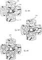
- FIG. 25shows tissue images acquired by four cameras using the methods described herein.
- FIG. 26illustrates only one of the four fields of view for one of the four cameras in the camera assembly.
- FIG. 27illustrates the four fields of view from the four cameras, each overlaid with at least one other field of view, to give the physician a 360 degree view.
- FIGS. 28A, 28B and 28Cillustrate an exemplary method of ablating cardiac tissue.
- FIGS. 29A, 29B and 29Cillustrate an exemplary method of ablating cardiac tissue.
- FIG. 30is an exemplary schematic of the electrical aspect of an exemplary embodiment.
- FIG. 31illustrates mapping signals from a plurality of channels.
- FIGS. 32 and 33illustrate aspects of an external console.
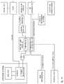
- FIG. 34illustrates an exemplary block diagram of a cardiac ablation system.
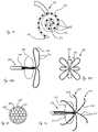
- FIG. 35illustrates exemplary information and indicators that can be superimposed on the images from the cameras.
- FIG. 36represents an exemplary flexible circuit for application to the outer surface of a balloon.
- FIG. 37shows an assembled flexible circuit affixed to a balloon.
- FIGS. 38A and 38Billustrate a composite view as described herein from a four camera array as presented to the user on a display.
- FIGS. 39 and 40illustrate an exemplary embodiment of an ablation catheter wherein the balloon is configured for contact (physical) measurements.
- FIG. 41illustrates a portion of an exemplary ablation and visualization catheter, which includes a locational element.
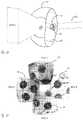
- FIG. 42represents a cardiac ablation catheter within a left atrium and within a global reference frame.
- FIG. 43illustrates an exemplary ablation and visualization catheter in contact with atrial tissue.
- FIGS. 44A, 44B, 44C, 44D, and 44Eillustrate exemplary steps in a process in which a system can be used to create a patient map, and in this embodiment the patient map includes the surface of a left atrium.
- FIG. 45illustrates an exemplary view from a camera from inside an expandable membrane of an exemplary visualization and ablation catheter.
- FIGS. 46A, 46B, 46C, and 46Dillustrate exemplary patient maps in 3 space.
- FIG. 47 Aillustrates exemplary landmarks that can be mapped into a patient map.
- FIG. 47Brepresents fields of view from a plurality of camera relative to a left atrium and some exemplary landmarks.
- FIG. 47Cillustrates an exemplary patient map that includes a plurality of captured and tagged images, and includes exemplary landmarks.
- FIG. 47Dillustrates an exemplary patient map that includes a plurality of captured and tagged images, and includes exemplary landmarks, while excluding some expandable member components from the field of view.
- FIG. 48Aillustrates visualization system images, with indicators to distinguish between the presence of blood and the lack of blood adjacent the expandable member.
- FIG. 48Billustrates the view from 48 A after an ablation procedure, with an additional indicator of a burned region of tissue.
- FIGS. 49A, 49B, and 49Cillustrate an exemplary process using an exemplary marker to estimate CS.
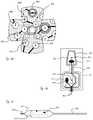
- FIGS. 1 A- 1 Cillustrate a distal portion of an exemplary cardiac ablation catheter.
- FIGS. 1 A- 1 Cshows expandable member 10 in an expanded configuration.
- FIG. 1 Ais a distal view
- FIG. 1 Bis a perspective view
- FIG. 1 Cis a side view.
- the cardiac ablation catheteris configured to deliver ablative energy to tissue such as cardiac tissue and to ablate the tissue.
- Expandable member 10includes membrane, or balloon, 12 and a plurality of energy delivery elements 14 secured to the exterior of membrane 12 .
- energy delivery elements 14are electrodes configured and positioned to deliver ablative RF energy to tissue when expandable member 10 is inflated and to ablate the tissue, and are in electrical communication with an RF generator (not shown) configured to generate RF energy.
- FIG. 1 Dillustrates expandable member 10 in a collapsed, or deflated, configuration prior to full inflation.
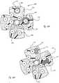
- FIG. 2Ais a side sectional view of the distal portion of the ablation catheter shown in FIGS. 1A-1 C.
- FIG. 2Bis a highlighted side sectional view of components within outer shaft 51 .
- FIG. 2Ashows membrane 12 expanded at the distal end of outer lumen 50 , which is the annular space between outer shaft 51 and irrigation shaft 5 5 .
- the distal end of membrane 12is secured, such as by press-fit and/or adhesive, to distal hub assembly 20 , between an inner member and an outer member of assembly 20 as shown.
- the proximal end of membrane 12is secured to the outer surface of irrigation shaft 55 .
- Hub 20is secured to guide wire shaft 54 , which in this embodiment defines guidewire lumen 53 so that the ablation catheter can be advanced over a guidewire (not shown).
- Guidewire shaft 54 and irrigation shaft 55are adapted to be axially movable relative to one another, which allows the distal end of membrane 12 to be moved relative to the proximal end of membrane 12 . Relative movement between the two components can allow for the shape of the balloon to be changed. The movement also assists in transitioning expandable member 10 to a collapsed configuration, as shown in FIG. 1D .
- Visualization system 30includes a camera assembly 32 and illumination sources 35 disposed on the guide wire shaft 54 .
- the camerasare configured to enable real-time imaging of the procedure from within the expandable member 10 to visualize the membrane and electrodes, cardiac tissue when the membrane/electrodes and cardiac tissue interface, as well as lesion formation during the ablation procedure, as is described in more detail below.
- FIG. 2Bshows radially outer shaft 51 , irrigation shaft 55 that defines irrigation lumen 52 , and guide wire shaft 54 that defines guidewire lumen 53 .
- the materials of the membranes 12 described hereincan vary. Generally, the membrane material is thin, readily foldable into a low profile and refoldable after expansion.
- the materialscan be elastic, inelastic, stretchy, non-stretchy, compliant, semi-compliant, or non-compliant.
- membrane 12has an expandable structure and can be constructed of materials such as those materials used in the construction of balloon catheters known in the art, including, but not limited to polyvinyl chloride (PVC), polyethylene (PE), cross-linked polyethylene, polyolefins, polyolefin copolymer (POC), polyethylene terephthalate (PET), nylon, polymer blends, polyester, polyimide, polyamides, polyurethane, silicone, polydimethylsiloxane (PDMS) and the like.
- PVCpolyvinyl chloride
- PEpolyethylene
- POCpolyolefin copolymer
- PETpolyethylene terephthalate
- nylonpolymer blends
- polyesterpolyimide
- polyamidespolyamides
- polyurethanesilicone
- PDMSpolydimethylsiloxane
- Membrane 12can be constructed of relatively inelastic polymers such as PE, POC, PET, polyimide or a nylon material.
- Membrane 12can be constructed of relatively compliant, elastomeric materials including, but not limited to, a silicone, latex, urethanes, or Mylar elastomers. Membrane 12 can be embedded with other materials such as for example, metal, Kevlar or nylon fibers. Membrane 12 can be constructed of a thin, non-extensible polymer film such as polyester or other flexible thermoplastic or thermosetting polymer film. In one embodiment flexible membrane 12 can be about 0.001′′ to about 0.002′′ in thickness to provide sufficient burst strength and allow for foldability. In some embodiments it is preferable to have the electrode mechanical properties as close to the membrane mechanical properties as possible. One way of providing this is to use an inelastic membrane that will not stretch as it is expanded. This helps secure the branches to the membrane. Membrane 12 has a front, or distal, face that is generally flat but can have other shapes as well.
- Expandable member 10includes what is generally referred to in U.S. Pat. No. 8,295,902, issued Oct. 23, 2012, and U.S. Pub. No. 2012/0071870, published Mar. 22, 2012, as flex circuits.
- a flex circuit as used hereingenerally refers to a conductive layer, an insulation layer, and optionally a substrate layer.
- a flex circuitis in electrical communication with at least one electrode.
- FIG. 8is a flat view showing three individual flex circuits that are secured to the exterior of membrane 12 .
- Each of the three flex circuitsincludes six energy delivery elements 14 , and a tail terminating in termination 41 for the six conductive traces, one for each of the six electrodes.
- the terminationsmay be in the form of a connector or solder pads or other such suitable interface.
- the terminations 41extend proximally from energy delivery elements on the expandable member, one of which can be seen in FIG. 1D .
- Each of the tailsbranch off into three branches 16 , each one of which includes two energy delivery elements.
- Each of the two side branches 16extend away from the longitudinal axis of the connector at substantially the same angle and each of two electrodes on a side branch is disposed at the same axial position (in the distal/proximal direction) as the other corresponding electrode on the other side branch.
- the central branchinitially extends along the same general direction as the longitudinal axis of a tail, and the first electrode on the central branch is axially disposed at the same general location as the second electrodes on the right and left branch.
- the central branchthen extends away from the longitudinal axis of the tail, and the second (distal) electrode on the central branch is disposed further distally than the other five electrodes on the flex circuit, and is disposed radially (relative the longitudinal axis of tail) at the same general position as the first (proximal) electrode on one of the other side branches.
- the six electrodes on one of the flex circuitsare labeled A-F.
- the two side branches of the flex circuitinclude electrodes A-B and E-F respectively.
- the central branchincludes electrodes C and D. In the flat view, electrode C (the distal electrode of the central branch) is axially disposed at the same general position as electrodes B and F.
- Electrode Dis disposed further distally than the other five electrodes, and is positioned radially in the same general position as electrode A. Electrodes A and E are disposed in the same general axial position, as are electrodes B, C, and F. Each of the three flex circuits is positioned on the expandable member, and the arrangement and size of electrodes provides for eighteen electrodes secured to the expandable member. As can be seen in FIGS. 1A and 1B , there are three electrodes closely surrounding hub 20 .
- FIG. 9Aillustrates a portion of one of the flex circuits in FIG. 8 (the flex circuit in which termination 41 is at the “6 o'clock” position), including six energy delivery elements 14 .
- FIG. 9Ashows as alternative embodiment in which the distal electrode on the central branch 16 extends to the right on the page rather than the left, as is shown in FIG. 8 . This arrangement provides the same general arrangement of the eighteen electrodes on the balloon.
- FIGS. 1A-1Cthere are three of the flex circuits from FIG. 9A disposed on membrane 12 , and thus eighteen energy delivery elements secured to membrane 12 .
- FIG. 9Billustrates the exemplary different layers of the flex circuit from section S-S from FIG. 9A .
- Electrically non-conductive substrate layer 13is deposited on membrane 12 , upon which conductive layers, or traces, 15 are deposited. Insulation layer 17 is deposited on top of conductive layers 15 except where the electrodes 14 are located. For example, to the left in FIG. 9B , an electrode 14 is disposed on electrically conductive element 15 , thus electrically coupling electrode 14 and conductive layer 15 , which is electrically coupled to an RF generator. On the right side of FIG. 9B , insulation layer 17 prevents conductor 15 on the right side from being electrically coupled to electrode 14 . Instead, the conductor 15 on the right side will be electrically coupled to the distal electrode on that branch. Each individual conductor 15 is therefore electrically coupled to only one electrode 14 .
- each of whichis individually coupled to one electrode.
- the electrodesare sized and configured to extend over a portion of the flex circuit and a portion of membrane not covered by the flex circuit. In this manner a large surface area electrode can be deposited onto and secured to the membrane.
- Each electrodeis shown with an irrigation aperture in the middle thereof, as is described herein to irrigate tissue adjacent the electrodes and to prevent the irrigation fluid inside the membrane from becoming too hot and interfering with the tissue ablation.
- the conductor or conductive layer 15can be a material such as, but not limited to, a metal or metal foil of copper, gold, silver, tin, nickel, steel, cupronickel (copper-nickel alloy), KOVAR (nickel-cobalt ferrous alloy) or other material.
- more than one conductive materialcan be used in the conductive layer 15 .
- a conductive layer 15 of coppercan be plated with a thin layer of an additional conductive material at the conductive pad beneath electrode 14 .
- the thin layer of additional conductive materialcan be gold.
- the flex circuit and its componentscan be manufactured using techniques as known in the art.
- the materials used to create the electrodes 14can vary.
- the electrodes 14can be a thin film of an electro-conductive or optical ink.
- the inkcan be polymer-based for better adhesion to the membrane.
- the electrode materialcan be a biocompatible, low resistance metal such as silver, silver flake, gold, and platinum which are additionally radiopaque.
- Inksmay additionally comprise materials such as carbon and/or graphite in combination with the more conductive materials already described. The addition of carbon and/or graphite can increase the conductivity of the polymer matrix. When incorporated as fibers the carbon and/or graphite add additional structural integrity to the ink electrode. Other fiber materials may be substituted to attain the same end.
- the electrode materialis not particularly radiopaque
- additivessuch as tantalum and tungsten may be blended with the electrode material to enhance radiopacity.
- An example of an electro-conductive inkis provided by Engineered Conductive Materials, LLC (ECM) which is a polyurethane-based silver loaded ink.
- ECMEngineered Conductive Materials
- Creative Materials Inc.which manufactures conductive inks, films, as well as radiopaque inks.
- the electrodes 14can be applied to the membrane 12 and flex circuit using an adhesive.
- the electrode materialcan have adhesive properties or be an adhesive-loaded with conductive particles such as silver flakes such that electrodes 14 can adhere the components of the flex circuit to the membrane 12 .
- the adhesive layercan include a conductive or non-conductive material.
- the electrodes formed with electro-conductive or optical ink or thin metal filmcan be visualized under fluoroscopy to provide a general sense of the shape of the membrane and location of the electrode.
- radiopaque additivescan be included in the electrode material or radiopaque markers laid out next to, on top or below the electrodes as will be discussed in more detail below. Additionally, the bonding layer or substrate will be optimally comprised of a minimally reflective material.
- Electrodesare individually addressable, or can be used with any other electrode.
- the electrodescan operate in monopolar mode or bipolar mode, as is indicated in the exemplary schematic shown in FIG. 34 .
- Electrodes setscan be chosen such that the lesion is, for example without limitation, linear, a spot, or a hollow circle.
- FIG. 3illustrates the coupling of the distal end of membrane 12 and hub 20 , which can be press fit, adhesive coupling or a combination of both.
- each of the flex circuits at the locations of the electrodesincludes an irrigation aperture therethrough, and as shown are in the center of the electrodes.
- the irrigation aperturesalso prevent the inflation/irrigation fluid inside the membrane from becoming too hot, which would interfere with the ablation.
- Irrigation fluidwhich is also the fluid that inflates membrane 12 causing it to be reconfigured toward its expanded configuration, is pumped from a fluid source through irrigation lumen 52 , into membrane 12 , through the irrigation apertures (not labeled), and towards the tissue that is in contact with the electrodes to cool the target tissue.
- imaging member 30includes camera assembly 32 that includes a plurality of cameras 33 and a plurality of illumination, or light, sources, 35 (e.g., LEDs).
- Expandable member 10also includes diffuse reflector 22 that is secured to the external surface of membrane 12 .
- Reflector 22is a diffuse reflector adapted to create diffuse reflection of light incident upon it from the illumination sources.
- Reflector 22is adapted to reflect light in a diffuse manner, as opposed to specular reflection, to better illuminate as much of the camera field of view as possible. If the reflector were adapted for specular reflection rather than diffuse reflection, light from the illumination sources that is reflected from the reflector would appear in the camera's field of view as a localized spot and would not illuminate as much of the field of view as possible.
- Illumination sources 35are configured and positioned to provide illumination generally radially outward towards reflector 22 .
- Diffuse reflector 22thus diffusely reflects light forward toward the camera's fields of view.
- the illumination sourcesthus provide lighting for the cameras to visualize the procedure, including the tissue, and the lesion formation.
- the diffuse reflectoris printed on the exterior of the balloon.
- the diffuse reflectorcan be comprised of silicone or urethane resins filled with nonconductive white pigment such as TiO, BaO, BaSo4, styrene or other polymer beads, or of metal particles.
- Optimal materialswill be minimally reflective such as a black adhesive.
- the diffuse reflectoris secured to the membrane such that it does not completely overlap any of the electrodes, and is positioned so that the illumination sources, when activated, emit light towards the reflector.
- the diffuse reflector, or reflectorsis secured to the membrane at a location that does not extend all the way to the distal end of the membrane.
- the reflectoris secured to the membrane such that it does not extend further distally than the proximal-most electrode. In alternative embodiments, however, the reflector can extend distally to the proximal-most electrode in some locations around the membrane.
- the distal edge of the reflectorcan be curved rather than straight, and depending on the electrode layout on the membrane, some portions of the reflector may extend distally relative to the proximal-most electrode. If the membrane in its inflated configuration can be divided in half between the distal most location and proximal most location defining a distal portion and proximal portion, the reflector is disposed at least on the proximal portion. In the embodiment shown in FIGS. 1A-1C , the reflector is disposed only on the proximal portion.
- One aspect of the disclosureis an expandable member that includes a diffuse reflector but does not include any ablation element.
- medical devicesthat include an inflatable member and at least one camera and at least one light source therein can benefit from a diffuse reflector even if the device is not used for ablation procedures.
- a reflectorherein is described as being a diffuse reflector, there may be some uses in which a reflector that reflects light in a specular manner may be beneficial. Alternatively, a reflector can have portions that reflect light in a diffuse manner and portions that reflect light in a specular manner.
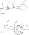
- FIG. 4shows an exemplary camera assembly 32 that includes four cameras 33 , which are disposed within camera hub 37 at an angle relative to the longitudinal axis of the catheter.
- Camera hub 37is secured to guide wire shaft 54 , and includes lumen 39 configured to receive guide wire shaft 54 therein.
- FIG. 5is another perspective view of expandable member 10 with a cutaway of the membrane.
- FIG. 6is an exemplary flat view of the LED flex circuit, including the LEDs, that is wrapped around the illumination hub proximal to the cameras.
- the field of view of the cameracan include the view of an electrode secured to the membrane.
- the electrodescan be highly reflective, such as if they are comprised of silver. Reflective electrodes causes light incident upon the electrodes to reflect into the camera field of view, which can cause the electrodes to appear as bright spots on the display, possibly interfering with viewing the procedure. It can thus be beneficial to include in the catheter a reflection adjuster that is adapted to reduce specular reflection of light from at least one of the plurality of ablation electrodes into the field of view of an imaging member.
- the reflection adjusteris a light absorber.
- the light absorbercan be positioned between the bottom of the electrodes and the membrane.
- the light absorberis a black adhesive that adheres portions of the electrode to the membrane, as well as acts as a light absorber.
- the reflection adjusteris an anti-reflective coating.
- anti-reflective coatingsinclude, for example without limitation, a deposited thin layer of TiO2, MgF2, and “moth eye” structures comprised of nanoparticles approximately 200 nm in diameter spaced 300 nm range, random microstructure secured to or created on the interior surface of the membrane that is adapted to reduce reflection.
- the anti-reflective coatingcan be adhered to only a portion of the membrane, such as the portion where the electrodes are disposed.
- an anti-reflective coatingcould be applied to only the distal portion of the inner membrane.
- a reflection adjusterwill reduce the amount of reflection from the bottom of the electrodes, creating a clearer image of the membrane and electrodes from within the membrane.
- a user interfacecan be used to control delivery parameters for any of the electrodes, and enabling the physician to easily determine and confirm that a given electrode on the video is a particular electrode on the user interface simplifies the procedures and ensures that the correct electrodes are being activated and used as intended.
- the catheterincludes an electrode identifier associated with at least one of the plurality of electrodes, and is some embodiments the catheter includes an electrode identifier with each of the plurality of electrodes.
- the electrode identifierneed not be unique to each of the electrode, but in some embodiments it is unique to each electrode.
- the electrode identifieris visually identifiable and allows an individual to visually associate the identifier with an electrode.
- the electrode identifieris an alphanumeric characters disposed on or near each of the electrodes.
- An example of this type of identifieris described and shown below.
- an alphanumeric charactercan be printed on the back of an electrode, or the back of a portion of the flex circuit that is associated with an electrode.
- An alphanumeric charactercan also be printed on the membrane near the electrode so that the identifier can be easily associated with a particular electrode.
- the electrode identifiersare colors associated with one or more of the electrodes.
- the electrodescan be color-coded so that a user can visually identify each of the electrodes.
- a group of electrodescan have a particular color, such as all of the electrodes connected to the same flex circuit are all one color.
- An additional example of an electrode identifieris the shape of the electrode so that the electrode or group of electrodes can be visually identified based on their shape.
- groups of electrodescan be circular, oval, hexagonal, rectangular, square, etc. Each electrode could have a unique shape to it as well.
- Electrode identifiersis described below in the context of overlaying field of view images from a plurality of cameras.
- FIG. 10illustrates each of the three flex circuit tails terminating in terminations 41 (one for each flex circuit) extending proximally from the distal end of the balloon and extending proximally within outer shaft 51 and secured to the outer surface of the proximal end of the balloon and irrigation shaft 55 .
- the proximal aspect of the configurationcan also be seen in FIG. 2B .
- six conductive wires 18can be seen extending proximally from one of the terminations 41 , each one of which is in electrical communication with one of the six electrodes in that particular flex circuit.
- the six wires 18extend the length of the catheter and are in communication with the RF generator.
- the six conductive traces 15extend the length of the catheter and are in communication with the RF generator.
- Camera flex circuit 43 for the visualization systemis also shown in FIG. 10 , extending proximally from the visualization system in the catheter.
- Exemplary materials for the membrane and flex circuit materialscan be found in U.S. Pat. No. 8,295,902, issued Oct. 23, 2012; U.S. Pub. No. 2012/0071870, published Mar. 22, 2012. Additional examples of membrane material include PET, Polyurethane, etc.
- Exemplary materials for the reflectorinclude metalized paints, silicone or urethane resin filled with nonconductive white pigment such as TiO or BaO or BaSo4, preferably non-conductive.
- Exemplary materials for the electrodesinclude silver filled silicone or urethane.
- Exemplary materials for the conductive tracesare conductive metals including copper or other such conductive materials.
- the insulation layerscan be known dielectric materials.
- Exemplary materials for the substrateinclude Kapton.
- ablation catheterscan include ablation and mapping electrodes secured to the exterior of the membrane.
- the area of tissue mappedis limited to the area of contact defined by the inflatable structure.
- the rotors being mappedcan, however, be larger than the contact area of the inflatable structure, making it more difficult and time consuming to properly map the atrial chamber for rotors.
- the ablation catheterincludes an inflatable membrane, and is also adapted to increase the area that can be mapped to an area that is greater than that defined by the expandable membrane contact surface.
- mapping armswhen appropriately stiff may provide a way to limit the accidental entry of the ablation elements into the pulmonary arteries thereby minimizing the risk of accidental ablation of the artery wall and consequent risk of subsequent stenosis.
- a mapping structure on which at least one mapping electrode is disposedis carried outside of the balloon and collapsed between the wall of the delivery catheter and the outside of the ablation catheter.
- the mapping structurecan be secured to the exterior of the ablation catheter.
- the one or more mapping structurescan be deformable splines, the use of which has been described in the cardiac ablation space.
- the mapping structurescan be made of nitinol and are adapted to deform. The mapping structure can thus expand on release from the delivery catheter and can be collapsed to a collapsed delivery configuration when the delivery catheter is advanced distally relative the ablation catheter.
- mapping electrode structureis adapted to be delivered through the guide wire lumen of the ablation catheters herein.
- FIGS. 11A and 11Bdepict an exemplary ablation catheter 300 that includes an array of mapping electrodes 302 (only one is labeled for clarity) carried on the surface of a plurality of reconfigurable mapping arms 308 .
- FIG. 11Ais a side view and FIG. 11B is a distal view.
- Arms 308together have a “basket” configuration and are disposed outside of the inflated membrane 306 .
- arms 308are in their expanded configurations, after being released from within the delivery catheter. Arms 308 are collapsed into the space between the delivery catheter and the ablation catheter 300 during delivery and retrieval, and are adapted to self-expand on release by retraction of the delivery catheter or delivery past the distal end of the delivery catheter.
- FIGS. 11A and 11Bshow catheter 300 with arms 308 in retracted positions in with proximal ends of arms 308 are retracted and positioned between the delivery catheter and the ablation catheter. Arms 308 are closer to the surface of expanded membrane 306 than in the expanded configurations shown in FIGS. 11A and 11B .
- FIG. 13is a distal view of a distal end of an exemplary ablation catheter 320 .
- the ablation catheterincludes an alternative spiral structure 328 that carries a plurality of mapping electrodes 322 (only three are labeled).
- the spiral mapping structurecan be adapted to be delivered through the guidewire lumen 323 , or it can be adapted to be expanded from between the delivery catheter and ablation catheter shaft, similar to the embodiment in FIGS. 11A and 11B .
- FIG. 11A and 11BIn the embodiment in FIG.
- the spiralin which the spiral structure is adapted to be delivered via a guidewire lumen, the spiral, in a side view, can be in a single plane, or the spiral can have a conical configuration that is adapted to be deformed into a single plane when the spiral is pushed distally into contact with tissue.
- Ablation electrodesare not labeled on the ablation balloon for clarity on FIGS. 13-17 .
- FIG. 14Ais a simplified side view illustrating an alternative ablation catheter 340 with a dedicated mapping structure 348 with a plurality of mapping electrodes 342 (only two are labeled) thereon.
- the two mapping arms 348have expanded loop configurations as shown and are adapted to be delivered through guidewire lumen 347 as shown. There may be more or fewer than two arms.
- FIG. 14Bis a distal view of an alternative embodiment in which the mapping structure 350 includes a plurality of loops in their expanded configurations.
- at least one loop 352has an expanded “height” (a distance measured from the longitudinal axis of the catheter along a line perpendicular to the axis) greater than a height of a second loop 354 .
- FIG. 15illustrates an exemplary configuration of mapping arms and electrodes 362 in collapsed configurations within guidewire lumen 360 , and is merely illustrative to show how a plurality of arms can be disposed within a guidewire lumen. More or fewer arms can be disposed therein.
- FIG. 16shows a simplified side view of an exemplary ablation catheter 370 in which the mapping arms 378 terminate at their respective distal ends 379 . That is, each arm has a free end.
- Catheter 370includes balloon 376 , guidewire lumen 377 , mapping electrodes 372 on arms 378 , similar to other embodiments herein.
- Any of the described mapping armsmay comprise a stiffening member such as NiTi wire such that on release the mapping member takes on a predetermined shape.
- mapping arms that are delivered through the guidewire lumencan alternatively be configured for delivery in the space between the ablation catheter and the delivery catheter, and vice versa.
- mapping armsmay be woven into a conical braid or braid structure which increases in diameter as it extends distally.
- the visualization systemallows for real-time visualization of the procedure with a view by one or more cameras disposed within the balloon.
- the visualizationallows for the entire procedure to be visualized, allowing physicians to assess the degree of tissue contact, and see the electrodes, tissue, and lesion formation as it occurs.
- FIG. 29illustrates only one of the four fields of view for one of the four cameras in the camera assembly.
- FIG. 30illustrates the four fields of view from the four cameras, each overlaid with at least one other field of view, to give the physician a 360 degree view (with the longitudinal axis of the catheter as the reference) of the treatment area. While there is a blind spot shown in the center of the four images, different lensing systems than those used in the current embodiments can allow for elimination of that spot. Since there are electrodes disposed around the entire catheter, the 360 degree view allows the physician to visualize an entire lesion that utilizes electrodes disposed around the catheter. The visualization of the entire procedure including lesion formation at any of the electrode locations is enormous helpful to the physician.
- One aspect of this disclosureis an exemplary method of generating a panoramic image display using images from a plurality of cameras attached to an endoscopic catheter.
- a plurality of images captured from a plurality of camerasare overlayed with at least one other image to create the panoramic image around the longitudinal axis of the ablation catheter.
- Two or more camerascan image various sections of the expandable member (from within the expandable member) and the anatomy, and the geometric relationships between the cameras are either known a priori (by design or measurement), or can be estimated from the images themselves using common anatomical features of the balloon as landmarks.
- mapping functionthat maps a pixel into a virtual unwrapped display screen, e.g. a dome-shaped screen, surrounding the cameras is computed.
- the imagesare then projected back to this virtual display screen using inverse projection, i.e., using cameras as projectors. Data in overlapping regions are combined using compositing including blending or some other means.
- FIG. 17is a side view of a distal portion of an exemplary visualization catheter.
- FIG. 17shows the geometry of the distal portion, which includes four cameras attached to the distal end of the central shaft of the catheter, surrounded by a membrane filled with saline. Each camera is imaging a section of the closed membrane from within the membrane.
- the conical shape shown in FIG. 17represents the field of view of one of the plurality of cameras.
- a plurality of radio frequency electrodesare secured to the exterior of the membrane.
- the camerasare able to visualize blood or tissue outside the balloon as well as the inner surface of the balloon. This provides a way to verify that the electrodes are in contact with tissue prior to starting the ablation and the balloon is located properly relative to anatomical landmarks such as a pulmonary vein.
- FIGS. 18A-18Dshow the orientations of the axes of the four cameras in relationship to the longitudinal axis of the catheter shaft.
- Arrows AP, BQ, CR and DS shown in FIG. 18Crepresent the axes of the respective cameras.
- OMis the longitudinal axis of the catheter shaft.
- the parameter “c”is the shortest distance between the axis of the catheter shaft OM and an axis of a camera (see FIG. 18A ).
- the camera axisis also at an angle ⁇ relative to the axis of the catheter shaft OM (see FIG. 18B ).
- the distal surface of the membranecan be modeled as an elliptical solid of revolution, as shown in the side geometrical view of FIG. 18D .
- Parameters a and bdefine the ellipsoid.
- the equator of the ellipsoidas labeled in FIG. 18D , is at a distance “d” from the point “O” shown in FIG. 18D .
- the imaging plane of the camera with the axis CRis at a distance e from C, as shown in FIG. 18D .
- FIG. 19shows the geometry of one of the four cameras field of view, and all four have the same geometry.
- a pixel in the imaging plane, P(u, v)is related to a point Q(x, y, z) in space by equations (1) and (2), where f is the focal length of the camera.
- FIG. 20shows a picture of a regular grid pattern target taken by a representative camera. As can be seen, barrel aberration causes the grid points farther away from center 390 to appear smaller and compressed to each other.
- mapping functionthat maps the original pixel coordinates, P(u, v), to a distorted pixel coordinate system due to barrel aberration, ⁇ tilde over (P) ⁇ ( ⁇ , ⁇ tilde over (v) ⁇ ), can be determined by using the grid target:
- the 3D surface of the ellipsoidal ballooncan be unwrapped into a 2D plane using the parameterization shown in FIGS. 21A-21C .
- the parameters of a and bdescribe the balloon as an elliptical solid of revolution.
- the parameter mcorresponds to the arc length along the balloon surface, starting from the zenith.
- the rotation angle ⁇describes the azimuthal angle of the solid of revolution.
- the unwrapped balloon surfaceis defined by the parameters (m, ⁇ ) in polar coordinates or ( ⁇ tilde over (x) ⁇ , ⁇ tilde over (y) ⁇ ) in rectilinear coordinates.
- a point on the balloon surfacecan be: (x, y, z).
- a planar unwrapped imagecan be constructed from the ellipsoidal balloon geometry by unwrapping the balloon surface as follows:
- [ x y z ][ a ⁇ ⁇ sin ⁇ ⁇ ⁇ ⁇ ⁇ cos ⁇ ⁇ ⁇ a ⁇ ⁇ sin ⁇ ⁇ ⁇ ⁇ sin ⁇ ⁇ ⁇ b ⁇ ⁇ cos ⁇ ⁇ ⁇ ] ( 4 )
- ⁇g ( m )
- g(m)is the well-known “Complete Elliptic Integral of the Second Kind.”
- the unwrapped 2D surfaceis defined by the polar coordinates: (m, ⁇ ) or in rectilinear coordinates, ( ⁇ tilde over (x) ⁇ , ⁇ tilde over (y) ⁇ ), where:
- the ( ⁇ tilde over (x) ⁇ , ⁇ tilde over (y) ⁇ ) coordinates of the point on the unwrapped balloon corresponding to each pixel in an image produced by a given cameracan be computed. Then the intensity of that pixel can be painted on the unwrapped balloon surface. If more than one camera projects data on to the same location on the unwrapped balloon surface, the data can be combined using any number of exemplary ways, such as blending, maximum value, adaptive blending, alpha blending, weighted averaging, etc. These techniques fall into the general category of “Compositing” as described in Foley et al., “Computer Graphics Principles and Practice”, 1990, Addison Wesley, 2nd Edition.
- FIG. 22shows a set of four camera images simulated using a known pattern, in this case, ablation electrodes 601 painted on the membrane. Electrodes 601 can be in the pattern of the eighteen electrodes shown in FIGS. 1A-1D . Electrodes 601 also have an identifier associated with them, in this case a unique alphanumeric character.
- FIG. 23shows the panoramic image generated by projecting the images from FIG. 22 back onto the unwrapped balloon surface using the methods described above.
- FIG. 25also illustrates exemplary electrode identifiers in the form of numbers printed on each electrode to enable visual identification of each of the electrodes.
- FIG. 25also illustrates how the collected images comprise common regions to images that are positioned adjacent to them, and that the common regions are overlapped to create the panoramic image.
- FIG. 24the panoramic image is generated by projecting the component images back onto the unwrapped balloon surface, but the electrodes 370 do not have electrode identifiers associated with them.
- FIG. 25shows tissue images acquired by four cameras using the methods described above.
- FIG. 25shows the panoramic image generated by projecting these images back onto the unwrapped balloon using the present invention.
- the exemplary method aboveacquires an image from each of a plurality of cameras, and combines the images to produce a panoramic image.
- the images from each cameracan be deformed using a geometric transformation.
- the deformingcan comprise information associated with the known geometric relationship between the cameras.
- the deforming procedurecan comprise geometric transformations generated using compositing in the overlapping areas of the images.
- the procedurecan comprise the use of weighted averaging.
- the procedurecomprises alpha blending.
- the deforming procedurecan comprise geometric transformations generated using feature tracking in the overlapping areas of the images.
- the characterization of the geometric relationship between the camerascan comprise the use of experimentally determined optical targets.
- the geometric relationshipcan be determined analytically by geometrically modeling the cameras, the fixture containing the cameras and the balloon.
- the geometric transformationcan include geometric transformations that map the balloon onto a planar surface while maintaining the distance between any arbitrary set of points on the 3D surface.
- the catheteris used to ablate cardiac tissue in the treatment of a cardiac arrhythmia.
- the catheteris advanced into the left atrium using known access procedures including guide wire and guide catheter techniques.
- Inflation/irrigation fluidis then pumped from a fluid source down inflation/irrigation lumen 52 to inflate the balloon to the configuration shown in FIGS. 1A-1C within the left atrium.
- the cameracan be activated at any time during the procedure, but generally before inflation so the physician can see if there are any problems with the inflation.
- the balloonis surrounded by blood, which can be seen.
- the catheteris advanced distally towards the atrial wall, and as the balloon contacts tissue the blood will be displaced, providing a clear view of the tissue.
- the physiciancan then determine if the balloon needs to be moved depending on the desired treatment tissue or desired area to map.
- An advantage of the visualization system in the devices hereinis that the physician can easily see, simply by viewing a display showing the camera fields of view, when the balloon is properly positioned. This also simplifies the system in that an analysis of reflected energy need not be performed, as in the case in some previous attempts at cardiac ablation.
- an external consoleis used to activate certain electrodes and control the energy delivery parameters of the procedure.
- An RF generatorgenerates the RF energy and it is delivered to the electrodes.
- An exemplary schematic of the electrical aspect of the embodiment shown hereinis shown in FIG. 33 . It is understood that eighteen channels are included while only three are shown. Alternate embodiments, not shown, may comprise more or less channels.
- the mapping capabilities of the systemare shown to the right of the electrode. Each electrode can be used in monopolar or bipolar mode, and impedance and voltage can be measured with each electrode.
- the generatoris configured such that electrodes can be used to map tissue, ablate tissue, and stimulate tissue, as desired. Ablation of cardiac tissue to treat aberrant signals is described generally herein and known.
- the generatoris also configured, however, to generate and deliver electrical tissue stimulation signals to the electrodes so that the electrodes stimulate the cardiac tissue.
- the schematic in FIG. 30illustrates that each electrode can be selected for either ablation or stimulation, while mapping from each electrode occurs continuously.
- the mapping portionincludes filters configured to filter out ablation bandwidths, and other non-essential bandwidths that may be delivered or otherwise present so that mapping can occur continuously.
- the disclosure hereinthus includes a generator configured such that each electrode can be used to both map and ablate tissue at the same time, or stimulate and ablate tissue at the same time.
- the systemis also configured such that ablation, stimulation, and mapping can all be occurring at the same time, although the stimulation and ablation would not be occurring at any given time from the same electrode.
- Stimulation of the cardiac tissuecan be done for a number of reasons.
- stimulation of tissuecan be performed during a diagnostics procedure to make sure the electrodes are working.
- RF energycan be delivered to a first electrode and sensed with another electrode, thereby transferring energy between pairs of electrodes to make sure the pair of electrodes is working.
- the stimulating energycould be delivered before the balloon makes contact with tissue or after it makes contact with tissue, as blood generally has low enough impedance so as not to prevent the diagnostic test.
- cardiac tissuecan be stimulated while tissue is being ablated with other electrodes.
- three electrodescould be used to deliver ablation energy to create a lesion between the three electrodes (e.g., a linear ablation), while an electrode on one side of the lesion could be used to deliver stimulating energy to an electrode on another side of the lesion to determine if the tissue is effectively ablated.
- tissue stimulation delivery signal capabilitiesinclude currents of 0 to 20 ma, pulse widths of 0 to 100 ms, repetition rates of up to 300 bpm. More preferably 0 to 10 ma, 0 to 10 ms, and up to 180 bpm. Stimulating cardiac tissue in these ways is different than mapping in that mapping measures impedance, while stimulation delivers energy configured to stimulate the cardiac tissue.
- the disclosure hereintherefore includes methods of stimulating cardiac tissue during an ablation procedure, including before the actual ablation, while ablating, or after the ablation has occurred.
- FIGS. 28A-28Cillustrate an exemplary method of ablating atrial tissue around a pulmonary vein ostia to isolate the pulmonary vein, and show it from the view generated by the four fields of view from the camera.
- FIGS. 28A-28Care meant to be the view the physician would see when using the system. Again, the blind spot in the middle can be removed depending on the camera assembly and arrangement of cameras therein.
- the balloonhas been advanced into contact with atrial tissue surrounding ostia 1501 of the pulmonary vein lumen 1502 . None of the electrodes have been activated in FIG. 28A , although mapping procedures could also take place at this stage to assess the conduction of the cardiac tissue.
- FIG. 28Aillustrate an exemplary method of ablating atrial tissue around a pulmonary vein ostia to isolate the pulmonary vein, and show it from the view generated by the four fields of view from the camera.
- FIGS. 28A-28Care meant to be the view the physician would see when using the system. Again, the blind spot in the middle
- FIG. 28Bshow certain electrodes “A” being activated and lesion regions 1503 starting to form in the tissue after the electrodes are making contact and power is applied. Electrodes designated “B” are not being activated in this example.
- FIG. 28Cshows continued ablation of tissue and formation of lesion region 1504 that generally extends around the pulmonary vein ostia.
- FIGS. 29A-29Cillustrate an exemplary method of using the system herein to create lesion for treatment of a rotor.
- FIG. 29Ashows the balloon advanced against cardiac tissue other than an ostia region, where none of the electrodes have been activated.
- FIG. 29Bshows only electrodes “A” being activated, and ablation lesions 1601 starting to form where the electrodes are in contact with tissue and activated.
- electrodes Aare the distal most electrodes from each of the three flex circuits.
- FIG. 29Cshows continued ablation and the formation of lesion region 1604 targeted at a rotor. The blind spot in the middle hides that the lesion extends over tissue that can't be seen.
- more than three electrodescan be used to perform a rotor ablation, such as four or electrodes.
- One aspect of the disclosureis a method of superimposing an image or images provided by the camera with information or an image that is an indication of at least one of a characteristic of the cardiac tissue and a characteristic of the ablation catheter.
- the superimposed images(or superimposed information and image) are presented to the physician in a visual display, such as a monitor, and can be part of a remote user interface.
- the aspectincludes methods and systems adapted to superimpose images.
- the methods and devices hereinare also adapted to obtain the information and superimpose the images.
- the information that is being superimposedcan be any suitable visual indicator of a characteristic of the cardiac tissue or a characteristic of the ablation catheter.
- the information that is superimposed onto the image from the camerasis the electrical activity on the cardiac tissue contacting the expandable member.
- the information that is superimposed onto the image from the camerasis the localized impedance of the ablation circuit.
- the information that is superimposed onto the image from the camerasis the temperature of the cardiac tissue opposed to the balloon.
- the camera comprising CMOS camerasare adapted to be responsive to light in the infrared range.
- the responsecan be used to estimate the temperature of the tissue before, during and or after ablation.
- the responsecan be interpreted by an algorithm and displayed superimposed to the visual light image from the cameras.
- an accelerometeris placed at a location in, on or near the ablation balloon.
- the accelerometercan be used to detect the orientation of the balloon in relation to gravity.
- the accelerometercan produce acceleration data that is used to determine the accelerometer position in relation to an initial position.
- the positioncan be used to construct a database of locations visited by the balloon and/or information collected by the electrodes on the balloon and/or RF power applied to the balloon electrodes.
- the collection of informationcan be used to reconstruct a model to provide guidance to the physician in relation to the locations that are treated and locations that need to be treated.
- FIG. 35illustrates exemplary information and indicators that can be superimposed on the images from the cameras.
- Indicators 402 and 404are examples of way to convey temperature of the tissue adjacent an electrode.
- indicator 402is a series of lines indicating qualitatively the temperature, such as “medium.”
- Indicator 404is a series of intersection lines and can indicate “high” temperature. Any type of visual indicators can thus be used to indicate the qualitative temperature of one or more tissue regions adjacent any of the electrodes.
- Superimposed information 406provides a qualitative indication of tissue temperature, in this example, 99 degrees.
- Information 406is next to the image of the electrode, whereas information 408 is information that is on the electrode image.
- Indicator 410is a red color superimposed on top of the electrode, providing a qualitative indication of “hot.”
- Information 414 and 416are superimposed to indicate that the respective electrodes are “on” and “off.”
- the superimposed informationis all the same type of information.
- each electrodecan, at the same time, be superimposed with information indicating the temperature of tissue.
- the type of superimposed informationcan be different for any of the electrodes.
- mapping signalscan be superimposed on the camera images as well.
- FIG. 36represents an exemplary flexible circuit for application to the outer surface of a balloon, with a thin polyimide substrate 101 approximately 0.002-0.003′′ thick and a total structural thickness between 0.004-0.006′′.
- the outlineis that of the final ablation pads 102 (only the large square and the triangle). Apertures 103 are for saline flow. Circuit traces 104 terminate in exposed areas on the ablation pads. Conductive silver paint is used to create the ablation pad geometry and the exposed trace provides conductivity.
- a black adhesivemay be used to darken the areas under silver painted ablation pads 102 to prevent reflections inside the balloon, as is described herein.
- One method of employing polyimide substrate 101can eliminate the black adhesive providing a thinner and more compliant mounting surface.
- the light absorbercan have the same base material as the electrode, but have no or little conductive properties. In these embodiments at least a portion of the electrode is thus not in direct contact with the expandable member, while the light absorber can be in direct contact with the expandable member.
- the light absorbing portionmay comprise a conductive material such as carbon nanotubes which will provide the light absorbing quality and the electrical conduction quality.
- a dielectric area 105is provided to prevent cross talk and conductivity to the blood or other medium.
- the proximal side of the flex circuithas two small solder pads 106 where the wires are attached.
- An assembled flexible circuit as represented in FIG. 3can be affixed to balloon 201 as shown in FIG. 40 , such balloon being located around a central stem 202 , and such stem having a system to capture the image of the internal surface of the balloon (not shown) and transmit such image to a display outside the patient.
- An optional long protrusion 203 distal to the triangle padwhich wraps around the front of the balloon to create a physical anchor for the circuit.
- an accelerometer 204is placed at a location in, on or near the ablation balloon, such accelerometer can be used to detect the orientation of the balloon in relation to gravity and to construct treatment relevant data sets as described herein.
- the image displaywill show the internal surface of the balloon fixed and everything outside the balloon (e.g., cardiac tissue) moving. This is due to the fact that the cameras, in the embodiments herein, are fixed in relation to the catheter and balloon system.
- FIGS. 38A and 38Billustrate a composite view as described herein from a four camera array as presented to the user on a display.
- the imagesare mapped to a composite image representing the arrangement and orientation of cameras carried by the balloon on the shaft within the balloon.
- the mapping registrationrelies on mapping common features within each camera field of view over each other where there are common features within two or more images.
- one electrode, the orientation registration electrodeis identifiable by a marking in the shape of an asterisk (as shown) which has been printed on the balloon prior to the electrode and is visible to the camera.
- each electrodemay be marked with its own unique identifier or some or all electrodes may have different shapes which help to identify them.
- the common fixed featuresinclude traces, electrodes and other fixed markings.
- FIG. 38Aillustrates an initial image taken just after burns 502 and 504 created by electrodes 514 and 510 respectively.
- the balloonis centered around a pulmonary vein 506 .
- FIG. 38Billustrates a second image captured by the camera array after the balloon is rotated.
- Each composite imagehas been processed such that the fixed features (relative to the cameras) are mapped to the user display in a fashion such that the registration mark (and hence the entire image) is rotated an amount equal and opposite to the rotation measured for the center of mass of one or more of the anatomical features around the center of the composite image such as burns 502 or 504 .
- the image of the fixed featureswill rotate while the portion of the image behind the fixed features will remain fixed as the balloon is manipulated.
- Disclosed heretherefore is a system to, through image processing, show the internal surface of the balloon rotating while maintaining still, or fixed, the image of everything outside the balloon (e.g., tissue).
- the image of everything that is not part of the catheterwill remain fixed, and everything that is part of the catheter will be shown in the video to rotate.
- the image that the user viewsshows the fixed features (e.g., electrodes) being rotated while anatomical features remain still.
- the anatomical featuresare the non-fixed features or non-balloon related features in the tissue such as, represented in this view, the pulmonary vein, and the images of burns created by ablation. This is accomplished even though the fixed features move as the camera moves.
- the mean rotation of the center of mass of one or more of the key anatomical featureare calculated relative to the location of the fixed features.
- the mean or other suitable representation of the rotation(s)is then used to rotate the composite image as presented on the user display.
- FIG. 34illustrates an exemplary block diagram of a cardiac ablation system, details of which are described herein. Any of the system components in FIG. 38 can be incorporated and used with any of the individual components described herein.
- the number and arrangement of the electrodes disposed on the expandable membereach of which is individually addressable and can be used to deliver energy in either monopolar or bipolar mode, provides for a wide variety of lesion formations without having to remove and insert a separate RF catheter.
- the exemplary methods shown in FIGS. 31 and 32are merely exemplary. Linear lesions and arc lesions are additional examples of lesion shapes that can be created depending on the desired ablation procedure.
- any of the electrodescan be used in bipolar mode with any other electrode as well. Depth and width of lesions may be controlled by choosing and/or varying what combination of electrodes are being used in bipolar and monopolar configurations. Monopolar configuration creates deeper, narrower lesions, and bipolar configuration creates shallower, wider lesions.
- One of the advantages of the devices hereinis that the number and arrangement of electrodes allow for a wide variety of lesion formations without removing and inserting a new catheter. And the visualization system allows for the entire procedure to be visualized.
- FIG. 7illustrates the distal end of the device incorporating a slidable sheathing tool 100 comprising sheathing tube 102 .
- balloon 12is collapsed as previously described and then the sheathing tool is slid over the collapsed balloon.
- the sheathing tube 102is then fit into the delivery catheter, not shown.
- the sheathing fixtureis then removed, leaving the collapsed balloon within the deliver catheter ready for advancement to the delivery site.
- One aspect of the disclosureis a delivery catheter comprising concentric sheaths as a steering mechanism with a mapping system built into the distal tip, where a mapping basket resides during delivery in the space between the two concentric shafts and on delivery is pushed forward out into the heart chamber. Examples of deployable mapping baskets are described above.
- An ablation cathetermay then be delivered through the delivery catheter with the mapping basket in place. Target locations for ablation can then be identified using the electrodes on the mapping basket and target locations are then ablated with the ablation catheter. The location of the ablation catheter may in addition be identified and verified by the mapping basket.
- an ablation catheterthat includes an electrode structure that is about 1 cm to about 5 cm in diameter and resides on the end of an inflatable or expandable structure and may comprise any of the following: an ablation catheter with a balloon carrying multiple electrodes.
- the multiple electrodesare used alternatively as a single ablation electrode then as a set of individual impedance sensing electrodes capable of monitoring the inter electrode impedance. Such measurements are useful in characterizing the efficacy of the burn resulting from the ablation and/or mapping the ablated area before or after the burn.
- contact pressure sensitive electrodesmay be incorporated as a means of verifying appropriate contact of the electrode to the cardiac tissue.
- irrigationis provided as described elsewhere herein, wherein the irrigation system incorporates a pressure sensor.
- contact pressuremay be inferred from changes in pressure within the irrigation system associated with increasing the outflow resistance at the irrigation outflow ports press against tissue.
- a balloon within a balloon configurationis used such that irrigation pressure may be isolated from inflation pressure. The change in pressure within the inflation system then is directly correlated to the contact pressure.
- coolingmay be provided by recirculation within the balloon as opposed to irrigation.
- the contact pressure of an electrodeis measured by impedance matching.
- An alternate means of characterizing the quality of lesionsis to measure changes in acoustic impedance in the ultrasonic pass band. The acoustic impedance will be changed from that of normal tissue both as a function of temperature and denaturation.
- a forward looking US transpondercan be incorporated in the balloon or on the surface of the balloon.
- Such a sensormay be embodied as an array of one or more transponders, an array of one or more transmitters and an array of one or more receivers, or a single transponder.
- temperature of the lesionmay be monitored by microwave radiometry.
- FIGS. 39 and 40illustrate an exemplary embodiment of an ablation catheter wherein the balloon is configured for contact (physical) measurements.
- Contact pressure of the balloon and therefore electrodesas characterized by variations in the internal balloon pressure resulting from irrigation holes in the balloon which pass through electrodes being occluded as the electrode is pressed against the tissue. Pressure will increase transiently as the balloon is pressed against the tissue and then reach a new equilibrium associated with any decrease in outflow resistance associated with the occlusion or partial occlusion of irrigation ports.
- This contact pressurecan be mapped by previous experiments to an electrode contact surface area.
- a visual contact monitorcomprised of a camera within the expandable structure monitors contact as a change in the visual appearance of transparent portions in the balloon. The changes in visual appearance result from differences in the appearance of blood and tissue in contact with the expandable member.
- Contact monitoringmay be used to control power delivery. Measurements of electrode contact obtained by any of the means described herein can be used to mediate the amount of power delivered to an electrode.
- One control algorithmlimits power to an electrode such that the power per area of contact surface is maintained at a constant level.
- FIG. 39illustrates a prototype balloon configured for contact measurement.
- Balloon 714is affixed to the end of shaft 711 .
- Strain gauge 713is affixed to shaft 711 and leads 712 which are interfaced with a strain gauge amplifier not shown.
- FIG. 40is a representation of a similar device in which all three strain gauges are configured in strain gauge assembly 755 on shaft 751 which comprises the leads to the strain gauge assembly.
- Balloon 754comprises electrodes 756 .
- the pressure of enclosed volumes of fluids or gels arranged in cells near the proximal attachment of the balloonmay be monitored via one or more pressure sensors.
- strain gaugesmay be replaced with displacement sensors. As indicated above measurements from such sensing systems can be mapped to an estimate of electrode contact surface.
- the balloon of FIG. 39is 2 cm in diameter and that of FIG. 40 may be 1 to 3 cm in diameter.
- the configuration of electrodes on the device of FIG. 40comprises eight electrodes. Such a small profile allows small delivery size and precise maneuverability.
- Such a systemis compatible with a single RF generator and may comprise an irrigation system, not shown, to minimize unwanted injury.
- This disclosurealso includes devices and systems adapted for, and methods of, creating a patient map, such as, for example without limitation, a patient map of at least a portion of a left atrium.
- Patient map creationcombines a plurality of different captured 2D images of the anatomy adjacent the expandable member, each of the plurality of captured 2D images visualizing at least one part of the patient (e.g., tissue) that was in contact with the expandable member when the image was captured.
- the methods and systemsrely on a known or determinable distance between a camera and a location on the expandable member, and a location element in fixed relation with the visualization system, such that the methods can tag each of the plurality of captured 2D images with a position and orientation (together referred to herein as “location) of the 2D image in a global frame of reference.
- the plurality of 2D imagecan then be placed in a 3 space (a space defined by 3 coordinates—x, y, z) at their tagged position to create the patient map, which can then be displayed on a monitor or screen.
- Patient maps as used hereincan be represented as projections in 2D or 3D on the screen. For example, a 3D view of the patient map can be displayed, or a 2D representation of the patient map can be displayed on the screen.
- the mapping hereinincludes combining different images captured by the visualization system, wherein the images are captured as the visualization system is moved within and placed in contact with the tissue of the patient (e.g., by moving the catheter or field of view of the camera). As the visualization is moved relative to the patient, a plurality of different 2D images are captured and used to create the maps herein.
- volume patient mapswhich can be generated using, for example, ultrasound systems, CT systems, and MRI systems.
- Volumetric mapsare generally created by obtaining 2D slices of a patient using the imaging system, which are then combined into a volume of at least a part of the patient.
- the systemscan allow a user to scan through the 2D slices or the 3D composite to visualize different parts of the volume.
- the volumes created using these systemsare different than the patient maps described herein.
- tissue locational mapping systemssuch as those that can map a left atrium
- a point-by-point mapping systemuse the relatively large number of individual points to create a 3D patient map.
- Systems hereincan create tissue maps in 3 space without having to rely on this type of point-by-point process.
- the medical devicee.g., cardiac ablation catheter, cardiac visualization and mapping catheter
- a visualization systemsuch as any of the systems herein including one or more cameras
- a locational elementin a fixed position relative to one or more components of the visualization system.
- a locational elementis generally referred to herein as one or more components whose position and/or orientation can be detected relative to a global frame of reference.
- the Aurora electromagnetic tracking systemsold by NDI Medical (located in Waterloo, Ontario, Canada N2V 1C5) utilizes a field generator that emits a low-intensity, varying electromagnetic field within which the patient is placed to track the position of a sensor, which can be a plurality of orthogonal coils.
- the electromagnetic tracking system and softwaredetermines the position and orientation of the sensor within the global frame of reference.
- an ablation catheter having one or more visualization elementscan also include a locational element in the form of a three orthogonal sensor coils, whose position and orientation can be sensed by a tracking system, such as an electromagnetic tracking system such as the Aurora system sold by NDI, CARTOTM, or the EnSiteTM NavXTM systems.
- a tracking systemsuch as an electromagnetic tracking system such as the Aurora system sold by NDI, CARTOTM, or the EnSiteTM NavXTM systems.
- other magnetic or RF field detectorssuch as magneto restrictive sensors may replace the coils.
- the locational elementhas a fixed, or at least known, position and orientation relative to the visualization system
- information obtained with the visualization systemcan then be associated with the tracking system's global frame of reference.
- the methods hereindetermine the location and orientation of a subsurface, or portion, of the target surface, and then compile the subsurfaces into a representation, or patient map, of the target surface.
- Some methodsare also adapted to image surface structural features (anatomical or created) visualized by the mapping system and map such features onto the patient map of the target surface. Some methods herein are also adapted to characterize one or more anatomical structures in the target tissue and the location in the patient map. Exemplary anatomical structures include the inner surface of a chamber of a heart, such as a left atrium, and exemplary structures include trabeculations, pulmonary veins, corina, vessels just behind the endocardia a septum or other natural features visible via light to which the camera is sensitive. Some methods herein are also adapted to characterize physiological processes occurring within or on the surface of the modeled tissue.
- Exemplary physiological processesinclude electrical signals, such as rotors or electrocardiological signals traveling through the cardiac muscle, and are described in more detail below. Some methods herein are also adapted to characterize stimulatable physiological structures occurring within or near the surface of the modeled tissue. Exemplary stimulatable physiological structures include autonomic ganglia, Bachmann's bundle, the phrenic nerve. Some methods herein are also adapted to characterize injuries marking created on and or in the tissue by the medical device such as burns, dye markings, or other injuries.
- FIG. 41illustrates an exemplary medical device adapted for use in creating a patient map.
- FIG. 41shows a distal portion of ablation catheter 420 , wherein ablation catheter 420 is similar to some catheters above.
- Catheter 420includes expandable membrane 422 , with irrigation holes, secured to a distal region of elongate body 424 .
- locational element 426 and visualization system 428Within expandable membrane 422 are locational element 426 and visualization system 428 .
- Visualization system 428includes one or more cameras 430 and light source 432 .
- Catheter 420also includes diffuse reflector 434 .
- Locational element 426is secured to inner shaft 436 , which can include a guidewire lumen therein.
- Locational element 426has a position and orientation that are fixed relative to the one or more cameras 430 , including the camera field of view (one of which is shown as “FOV”).
- Locational element 426can include a coil whose position in 3 space (x, y, z) and orientation can be detected by a tracking system
- Catheter 420also includes one or more markers carried by the expandable membrane. “Carried by” as used in this context can be one or more elements external to an external surface of the expandable membrane (directly or indirectly secured thereto), something integral with the membrane, or something internal to the inner surface of the membrane. Examples of external markers include RF electrodes (ablation and/or sending) or one or more components of a flexible circuit secured relative to an external surface of the expandable membrane.
- a markercan be a visual marker such as visual markings with known dimensions and distances between them (e.g., lines or other shapes with known dimensions and known distances between them).
- the catheteralso includes one or more electrodes (ablation and/or sensing) and one or more flex circuits carried by the expandable membrane, examples of which are described above.
- Catheter 420can be used in any of the manners described above for any of delivery, inflation, ablation, and sensing.
- An exemplary use of the methods and systems hereinis in creating a patient map of at least a portion of a chamber of the heart, such as the surface of a left atrium and it's structural and electrical features, such as the pulmonary veins, trabeculations, septum, electrical signals traveling through the muscle including rotors and other aberrant signals, nerves, nerve bundles passing through or near areas of the heart, and any other conduction features.
- a chamber of the heartsuch as the surface of a left atrium and it's structural and electrical features, such as the pulmonary veins, trabeculations, septum, electrical signals traveling through the muscle including rotors and other aberrant signals, nerves, nerve bundles passing through or near areas of the heart, and any other conduction features.
- Such an exemplary systemcan be used in the treatment of atrial fibrillation and other similar diseases.
- FIG. 42illustrates the distal end an embodiment of a patient mapping (which may also be referred to here as surface mapping) and visualizing ablation system.
- a patient mappingwhich may also be referred to here as surface mapping
- the distal end of the ablation catheter 1100 secured to and delivered by elongate shaft or catheter 1110is contacting the left atrium posterior surface 1210 within a patient's chest 1200 .
- One of the pulmonary vein ostia 1211is labeled on the pictured surface.
- the left atrium and its posterior surfaceare in a 3D mappable volume 1190 .
- FIG. 43illustrates a side sectional view of the distal region of a surface mapping and visualizing ablation system (which can be the same or similar to ablation catheter 420 in FIG. 41 ), contacting the posterior surface of a left atrium 1210 .
- the inflatable membrane or balloon 1120is shown contacting atrial wall tissue 1210 around a pulmonary vein ostia 1211 .
- Two cameras 1130 and associated fields of view 1135can be seen within the balloon. The cameras are carried by and on a tubular shaft through which a guide wire lumen passes.
- the cross section as shownshows four electrodes 1150 , two of which are contacting atrial tissue and two of which are not.
- a locational element 1170is disposed on and carried by the outer surface of the elongate member in which the guide wire lumen is disposed.
- the electrodes and/or the support circuitrye.g., flex circuits
- markersalso referred to herein as “visualization elements”
- a reference frame 1180(x, y, z axes) is shown superimposed on one of the cameras 1130 .
- FIGS. 44A-44Eillustrate exemplary steps in a process in which a system can be used to create a patient map, and in this embodiment the patient map includes the surface of a left atrium.
- the exemplary processcan be of use in providing an ablation treatment for the treatment of atrial fibrillation.
- Part of the processis determining, or characterizing, the position of one or more regions or points of interest on the tissue, within a global frame of reference.
- the global frame of referenceis defined by a tracking system that senses the position and orientation of the locational element.
- the location and orientation of position vectors associated with system components (e.g., camera) and features either in or on the tissuecan be summed to characterize the position of the point or region of interest within the global reference frame.
- Thismay include mapping position vectors defined in local frames of reference into positions defined within the global frame. This can include mapping the position of a feature, features, or tissue (or any other part of the patient) that is in contact with the expandable membrane into the global frame.
- Frames of referencewill begin with a capitol letter followed by “f.”
- Exemplary frames of reference described hereinare, the global frame (“Gf”), the locational element frame (“Lf”), and the reference frame of a Camera (“Cf”).
- Position vectorswill be designated herein by pairs of capital letters, the first letter indicative of a starting point, and the second letter indicative of an end point for a position vector.
- “GL”is an exemplary position vector, describing the position vector starting at the origin in the global frame “Gf” and ending at the locational element. GL is typically measured by the locational tracking system, an example of which is the Aurora system.
- Vector “LC”describes the position vector measured from the locational element to a camera. LC is typically fixed by the design of the catheter. “CS” is a position vector measured from a point on a camera to a point on a visualized surface. CS is typically calculated as set forth below. “GS” is the position of point “p” on a surface measured from the origin of Gf to the point. When a position vector is listed with a subscript, the subscript indicates the frame in which it is characterized. An element characterized in the global frame may or may not use the frame indication.
- FIGS. 44A-44Eillustrate, conceptually, position vectors and relative frames of reference, used in the process of characterizing a point P on the atrial wall, the point described by the position vector GS.
- FIG. 44A-44Eillustrates a global reference frame “GF”, with axes x, y, z, which provides the reference frame for the position and orientation of the locational element.
- FIG. 44Ashows, and FIG. 44B shows in more detail, a distal region of an exemplary catheter 450 , for which an expandable member is in contact with a surface of atrial wall 456 about an ostium of one of the pulmonary veins 460 .
- Catheter 450can be used in a process to create a patient map of the surface of the atrial wall, whether a 2D or 3D map.
- FIGS. 44A and 44Bshow a position vector “GL” for the locational element 457 , as well as a position vector “GS” for a point on the atrial wall surface whose position within the global reference frame is desired. Three of these points can be used to characterize a surface to map into the global frame of reference.
- FIG. 44Cillustrates the view of FIG. 44B , but the expandable member has been removed for clarity.
- Locational element 457can be seen near the distal end of the catheter, the position and orientation of which can be characterized by the global mapping system which defines the global frame Gf.
- the visualization systemincludes three cameras (more or fewer can be used; any assembly herein or known can be used), whose position and orientation relative to the locational element are fixed.
- the visualizing systemalso includes one or more light sources (such as any of the lighting assemblies herein or known), which can also be seen secured to the catheter.
- the frame of reference “Cf” for a first camerais also shown, as is the position vector “CS” from the camera to the point of interest on the surface of the atrial wall.
- Each camerahas a reference frame Cf associated with its field of view and is aligned such that one axis of the reference frame Cf is collinear with the optical axis of the camera.
- FIG. 44Dshows just the references frames and the position vectors.
- FIG. 44Eshows a close-up view of the position vector GL for the locational element, the locational element frame of reference “Lf,” position vector “LC” from the locational element to the camera, camera frame of reference “Cf” the position vector from the camera to the point of interest on the atrial wall, the position vector GL for the locational element, and position vector SP for the point of interest on the wall.
- TSfEf(V)A transformation of the coordinates of a position vector in one frame to another is described herein as TSfEf(V), which describes a transformation from “Sf”, the starting frame, to “Ef”, the ending frame, on position vector “V”.
- FIG. 45illustrates an exemplary view from a camera from inside an expandable membrane of an exemplary visualization and ablation catheter.
- the viewincludes expandable membrane 470 , inner ablation electrode 472 and a portion of outer electrode 474 , which are in electrical communication with individual conductive traces extending along a substrate, examples of which are described herein.
- CSillustrates the end point of the position vector from the camera to the point of interest.
- the methodsthus far take advantage of contact between a portion of the expandable member and at least a part of the patient (e.g., atrial wall).
- the distance between the camera and the contacted part of the patientis estimated to be the same as the distance between the camera and the expandable member that is contacting that particular part of the patient. This is because the expandable member is directly adjacent and in contact with the particular part of the patient.
- the distance between the camera and the expandable membermay be known, or it may be estimated.
- the expandable memberis filled with inflation fluid (which may be also irrigation fluid flowing through irrigation holes in the expandable member), and the shape of the expandable member stays generally the same when in use.
- inflation fluidwhich may be also irrigation fluid flowing through irrigation holes in the expandable member
- the distance between the camera and every location on the expandable membercan be determined, assuming that there is a known expansion state or configuration of the expandable member.
- the position of the distal end of the expandable membermay be adjustable relative to the proximal end of the expandable member.
- the distance between the camera and the expandable membercan be determined based on the particular relative position between the distal and proximal ends of the balloon.
- the distance between the camera and the contacted tissuecan always be estimated based on the known distance between the camera and the expandable member. The distance may vary slightly due to very slight changes in configuration, however.
- One way in which to maintain the configuration of the expandable member when in useis to inflate the expandable membrane to or above a threshold internal fluid pressure, to ensure that the expandable member does not deform meaningful to prevent use of the known distances.
- a threshold internal fluid pressuree.g., at least about 0.8 psi (e.g., at least about 1.0 psi)
- the configuration of the expandable membercan stay the same, even when urged up against tissue.
- the distal end of the expandable membraneis secured to distal end of an elongate device that may include a guidewire lumen therein.
- a hubis disposed at the distal end of the elongate device.
- the elongate devicecan be moved axially relative to distal end of the general catheter shaft, which can change the shape of the expandable member.
- the systemcan be configured so that some amount of travel in the elongate device (generally as a result of an actuator on the external handle) can be correlated to a change in shape in the expandable member.
- the systemcan be adapted such that a position of an external actuator on the handle can indicate the configuration or shape of the expandable member.
- the relative axial position of the elongate devicecan be correlated to a particular configuration of the expandable member.
- the relative axial position of the elongate device or handle component that controls itcan be thus be used to determine the distance between the camera and the location on the expandable member.
- FIGS. 46A-46Dillustrate exemplary patient maps 600 in 3 space created according to the methods herein, including combining a plurality of 2D images 601 and 602 (each of which comprises 3 images from 3 different cameras), captured by cameras, and tagged with information indicative of the location and orientation of a locational element.
- the methods used to create the patient maps in 3 spacecan utilize a known/estimated or a calculated distance from a camera.
- the 3D models 600 shown in FIGS. 46A-46Dcan be created using the methods in FIGS. 44A-44E and the transformations between reference frames.
- FIGS. 46A and 46Billustrate two sets of camera images 601 and 602 , each comprising three overlapping images from three different cameras, combined and shown relative to the anatomical landmarks in a left atrium when the images were captured.
- the triangles shownrepresent an overlap in camera images where a single electrode in each camera field of view overlap.
- the captured and combined imagesillustrate electrodes 603 (only one labeled for clarity), burned tissue region 604 , and the fields of view from the cameras.
- the images framesare shown relative to anatomical landmarks including the pulmonary vein ostia 605 , and the surface of the tissue 606 can also be seen generally.
- FIGS. 46A and 46Billustrate the combined images in 3 space, relative to the anatomical landmarks.
- 46C and 46Dillustrate the images combined into 3 space, wherein the anatomical references (in this embodiment the pulmonary veins) can be visualized as cutouts to the images.
- the anatomical referencesin this embodiment the pulmonary veins
- the location of three pulmonary veins 605can be seen in FIG. 46D , one of which is at the intersection of three images, while portions of two of them can visualized as cutouts in two of the fields of view.
- FIGS. 46B and 46Dillustrate a 2D projection of the patient map that was created in 3 space.
- the 2D representationcan be displayed on a display or monitor, and be considered similar to FIG. 47D below.
- the same procedurecould be used to create a patient map of a larger portion of the surface of a left atrium.
- the patient maps shown in FIGS. 46A-Dcan also be mapped onto images obtained of surfaces obtained from other imaging systems such as MRI or CT systems.
- an MM systemcan be used to create a 3D surface of a patient's left atrium, and a patient map herein can then be mapped onto the MRI 3D surface.
- FIG. 47Aillustrates an exemplary portion of a left atrium, identifying relative positions of anatomical landmarks (not all of which can actually be seen inside a left atrium) such as the phrenic nerve 610 , Bachmann's bundle 611 , four pulmonary veins 612 , atrial appendage 613 , and mitral valve 614 .
- FIG. 45Aalso illustrates exemplary “created” landmarks that can optionally be mapped to any of the models herein, such burn landmarks 615 , which illustrate where tissue has been ablated or otherwise modified by any suitable ablation catheter. For example, once tissue has been ablated according to any ablation process, the location of the ablated tissue can be mapped to the patient map, and thus presented visually to the physician.
- FIG. 47Aalso illustrates a created landmark 616 in the form of dye injected into heart tissue or applied to the surface of the tissue.
- a created landmark 616in the form of dye injected into heart tissue or applied to the surface of the tissue.
- the landmarkcan even be an injury created during a procedure, such as an injury by a guide wire or other tool.
- the landmarkcan be a marking made intentionally on or to the tissue, but which does not harm the patient.
- the additional landmarkcan then be mapped into the model as if it were any other type of landmark.
- the hub of the expandable memberincludes an element that is adapted to deliver dye into the tissue, such as an actuatable needle in fluid communication with a dye reservoir, or port for needleless injection.
- an actuatable needlein fluid communication with a dye reservoir, or port for needleless injection.
- the needlecan be advanced into tissue, and dye can be injected through the needle and into the tissue, creating the landmark.
- Other anatomical featuresare also identified in FIG. 47A (e.g., superior and inferior vena cavas, coronary sinus, and autonomic ganglia).
- FIG. 47Billustrates two sets of images ( 620 ′- 620 ′′ and 621 ′- 621 ′′) obtained with a device having three cameras, wherein the sets of images were obtained when the device was in contact with the tissue.
- the two sets of imagesare combined using the methods herein.
- FIG. 47Cshows the two sets of captured images combined, and includes the landmarks within the fields of view.
- FIG. 47Cis an example of a patient map projected on a 2D plane and displayed.
- FIG. 47Calso illustrates electrophysiological landmarks mapped onto the patient map, including rotor representation 622 and indicator of aberrant electrical activity 623 , which can be sensed using any of the mapping electrodes 624 (only 1 labeled for clarity). Portions of ostia can also be seen.
- FIG. 47Dshows an exemplary displayed patient map as could be presented to a user, with a plurality of landmarks (and different types of landmarks) mapped to the patient map. Portions of three ostia 625 were in the fields of view. Burn landmarks 626 have been added to the patient map, which indicate locations of where tissue was ablated. Anatomical landmarks 627 (shown as “B” icons) are also included, which indicate the location of Bachmann's bundle, as well as landmarks 628 (shown as “P” icons), which indicate the location of the phrenic nerve.
- Creating a patient maprequires tagging at least two images for inclusion in the map.
- the images that will be taggedcan be tagged automatically, or can be tagged based on user input.
- the systemcan automatically tag all images in which contact has been made and use any of these (or all) of these images to create a map.
- the systemcan automatically capture images periodically or non-periodically.
- the systemcan be adapted to receive user input (e.g., pushing a button) to cause the tagging of the image to be used in creating the patient map. Any number of automatic or nonautomatic ways can be used to indicate what images should be used in the map creation.
- the maps created hereinmay be displayed in real-time, or the maps can be stored for later visualization and analysis.
- the methodincludes exciting tissue at a particular location using one or more electrodes on the expandable membrane, and then monitoring the response, and based on the response, the method could then map that location.
- the devicecan be positioned against tissue in order to attempt to excite Bachmann's bundle 611 (see FIG. 47A ). When a contraction in the ventricle is detected, the location of Bachmann's bundle can be mapped to the model. Alternatively, an excitation could attempt to over excite Bachmann's bundle to inhibit or interfere with a contraction. When it is detected that the contraction has been inhibited or interfered with, the location can be mapped to the model.
- the devicecan be used to excite the phrenic nerve, and the method then includes monitoring for a diaphragm contraction. If the diaphragm contracts, the location of the phrenic nerve can be mapped to the model.
- FIGS. 48A and 48Billustrate an additional exemplary created landmark that can be mapped to any of the patient maps herein.
- computer implemented methodse.g., algorithms detect and indicates where contact has been made between the expandable member and tissue. Any type of indicator can then be mapped to the map to visually indicate where contact has been made.
- the methodscan be adapted to detect the image color in the field of view in non-electrode and non-flex circuit regions. A white region indicates a lack of blood flow, and thus indicates that contact is being made against the tissue. A red color indicates blood flow, and thus a lack of contact between the device and the tissue. There can be degrees of red and white around any particular electrode, which may indicate partial contact between the device and tissue.
- the methodsthen map the region of contact (or the region of non-contact) to the patient map, which provides a visual indicator mapped on the patient map for the physician to understand where contact between the device and tissue has been made, and where contact between the device and tissue has not been made.
- FIG. 48Aillustrates images prior to tissue ablation
- FIG. 48Billustrates the captured images after an ablation.
- the deviceincludes four cameras, the images from which have combined.
- the dotted areaindicates where blood is present adjacent the expandable member (due to lack of sufficient contact between the balloon and the tissue, thus blood is present between the balloon and tissue).
- White region 631indicates where the balloon is contacting the tissue, removing blood from the field of view, and appears white (or at least different than the red color indicating blood) in the image.
- Region 632 in FIG. 48B(shown as lined) indicates where tissue has been burned, or ablated, using the electrodes that are in contact with the tissue (as indicated by the lack of an indication of blood).
- FIG. 48Aalso illustrates another anatomical landmark 633 , which as shown is a rivulet of blood (seen as the contrast between red and white in the images).
- This rivulet of bloodis blood flowing from the pulmonary vein (into the left atrium) that is adjacent the device.
- the location of the ostiumis shown generally at 634 .
- the presence of the rivulet of bloodcan be used as an indicator of the location of the ostia, even if the ostia cannot be seen. The particular blood flow can thus provide an indication where a different anatomical landmark is location.
- FIG. 48Aalso indicates an overlap region 635 wherein images from two different cameras are overlapped to present the larger combined image.
- the distance between the camera and the expandable membermay not be known, and it may need to be calculated, or estimated.
- the distancemay vary and a way of estimating the distance can enhance the accuracy of the created patient map.
- One conceptutilizes a marker's known dimensions and the visualization system's ability to capture an image of the marker to determine a distance between the camera and a tissue region of interest. When the expandable membrane and associated marker are placed into contact with tissue, the distance between the contacted tissue and the camera is virtually the same as the distance between the marker and the camera.
- Determining the distance between the camera and markerthus provides the desired distance between the camera and the contacted tissue.
- the distance between the camera and markere.g., an electrode carried by the balloon, flex circuit component, etc.
- the distance between the camera and markercan be determined by, after contacting tissue, quantifying the visualized dimensions, and comparing them to the known marker dimension relative to the field of view. If the marker's relative dimensions in the captured field of view stay the same, the marker would be at the known distance from the camera, and thus the tissue region would be at the known distance from the camera.
- the marker (and tissue) or part of itwould be closer to the camera than if the balloon were in the predetermined inflation state, likely due to the balloon being distorted inward by collapsing the balloon against the tissue.
- the dimensions of the marker in the captured imagecould also, for example, indicate if the marker was skewed due to engagement with a tissue surface that is not coplanar with the image plane. This could be an indicator a curvature in the tissue surface.
- the marker dimensions in the captured imagecan thus help determine the distance between the marker and camera, and the distance between the camera and the tissue region.
- the known relationship between the camera field of view and the global frame of reference(characterized from the camera's fixed position and orientation relative to the locational element) can be used to place the tissue region into the global frame of reference.
- the processcan be repeated for a plurality of tissue regions, and a patient map can then be created by combining the plurality of imaged tissue regions into the global frame of reference, using, for example, known mathematical relations implemented in software.
- CSis an unknown position vector on the right side of the equation.
- GLcan be sensed by the tracking system, and LC is fixed by the design of the catheter.
- CScan be estimated (via calculation) using the known dimensions of the marker.
- FIGS. 49A-49Cillustrate an exemplary process using an exemplary marker to estimate CS.
- the markercan be any one or more of the following; the ablation element (e.g., electrode) or a feature of the ablation element or its supporting flex circuit, a portion of the guidewire shaft, a feature printed on or incorporated into the surface of the balloon or outer surface of the guidewire shaft, an element carried by the guidewire shaft, and an element carried by the camera housing.
- the ablation elemente.g., electrode
- the markercan be any one or more of the following; the ablation element (e.g., electrode) or a feature of the ablation element or its supporting flex circuit, a portion of the guidewire shaft, a feature printed on or incorporated into the surface of the balloon or outer surface of the guidewire shaft, an element carried by the guidewire shaft, and an element carried by the camera housing.
- xmis a known dimension of a visualization element
- pixtotis the total number of pixels across the camera's image plane parallel to the known length feature on the image plane of the camera
- pixrefis the number of pixels in the camera's image plane which span the known length feature on the image plane of the camera
- ais the angle comprised in the field of view. This applies where the pixels are evenly spaced and the horizontal and vertical pixel counts are equal.
- the balloonis in contact with the point of interest, and thus the calculated distance between the camera and the marker can then be used as an estimation of the distance between the camera and the point, or CS.
- CScan then be used to characterize the position vector GS of the point, in the global frame of reference. This procedure can be repeated for as many points or surface regions as desired to create a patient map.
- the reference featuresmay not be scaled precisely due to, for example, differences in distance between the camera and the reference feature when the particular image is captured.
- the distances between a camera and featurescan depend on how much contact is made between the expandable membrane and tissue.
- the patient mappingcan thus include automatically scaling one or more reference features in the images to create a patient map in which reference features are to scale, or as close to scale as possible.
- Systems hereincan be adapted with a plurality of visualization modes.
- the systemcan be adapted to generated maps in one or both of 2D planes and 3 spaces.
- the user interfacecan allow the user (e.g., physician) to choose between the modes.
- the user interfacecan be adapted to display both 2D and 3D models simultaneously.
- This disclosurealso includes methods of combining (which may also be referred to as stitching) images together to create a composite image.
- the imagescan be captured as the visualization system is moved within and relative to the patient.
- the imagescan be stitched together by utilizing common features in the images.
- Any of the landmarks hereincan be used as a common feature to combine the images together.
- natural landmarkssuch as an ostium that show up in multiple images can be used to stitch a plurality of images together that visualize the ostium.
- Other landmarkssuch as created landmarks can be used as a feature common to a plurality of images to combine the images.
- Electrophysiological landmarkscan similarly be used as a common feature to combine images.
- the methodcan use timing relationships of monitored signals to help stitch images together. For example, referencing FIG. 31 , the phase between signals can be used to help stitch the images together.
- the methodscan be used with a locational element and global frame of reference as set above, but the methods need not include the use of a locational element.
- the use of a locational elementmay make it easier to create patient maps by having a known sensed position and orientation in a global frame, but it may not be absolutely necessary if landmarks can be used to effectively create a useable map.
- the disclosurealso includes methods and systems that create maps of combined images that utilize any type of landmark, without the use of a locational element.
- the surface to be mappedwill be in motion during the mapping procedure. This is the case for instance when mapping the surface of the left atrium and the heart is beating. In such cases it is useful to capture a signal correlated with the motion, such as in this case an ECG, and temporally correlate the ECG with the data captured during the mapping process with the time at which it was acquired.
- a signal correlated with the motionsuch as in this case an ECG
- One way to accomplish this correlationis to tag both sets of data with a timestamp and use the timestamp to accomplish the correlation.
Landscapes
- Health & Medical Sciences (AREA)
- Life Sciences & Earth Sciences (AREA)
- Surgery (AREA)
- Heart & Thoracic Surgery (AREA)
- Engineering & Computer Science (AREA)
- General Health & Medical Sciences (AREA)
- Animal Behavior & Ethology (AREA)
- Veterinary Medicine (AREA)
- Biomedical Technology (AREA)
- Public Health (AREA)
- Molecular Biology (AREA)
- Medical Informatics (AREA)
- Biophysics (AREA)
- Physics & Mathematics (AREA)
- Pathology (AREA)
- Nuclear Medicine, Radiotherapy & Molecular Imaging (AREA)
- Radiology & Medical Imaging (AREA)
- Optics & Photonics (AREA)
- Pulmonology (AREA)
- Child & Adolescent Psychology (AREA)
- Anesthesiology (AREA)
- Hematology (AREA)
- Cardiology (AREA)
- Plasma & Fusion (AREA)
- Otolaryngology (AREA)
- Oral & Maxillofacial Surgery (AREA)
- Surgical Instruments (AREA)
- Measurement And Recording Of Electrical Phenomena And Electrical Characteristics Of The Living Body (AREA)
- Dentistry (AREA)
Abstract
Description
Where:
θ=g(m) (5)
and g(m) is the well-known “Complete Elliptic Integral of the Second Kind.” The unwrapped 2D surface is defined by the polar coordinates: (m, γ) or in rectilinear coordinates, ({tilde over (x)}, {tilde over (y)}), where:
| TABLE 1 | ||
| Parameter | Description | |
| 1 | a | Ellipsoidal balloon geometry | |
| 2 | b | ||
| 3 | c | Distance offsets | |
| 4 | d | ||
| 5 | e | ||
| 6 | f | ||
| 7 | φ | Camera angulation | |
| 8 | F | Barrel aberration mapping function | |
| G | |||
Claims (19)
Priority Applications (1)
| Application Number | Priority Date | Filing Date | Title |
|---|---|---|---|
| US16/432,243US11439298B2 (en) | 2013-04-08 | 2019-06-05 | Surface mapping and visualizing ablation system |
Applications Claiming Priority (18)
| Application Number | Priority Date | Filing Date | Title |
|---|---|---|---|
| US201361809629P | 2013-04-08 | 2013-04-08 | |
| US201361809636P | 2013-04-08 | 2013-04-08 | |
| US201361809646P | 2013-04-08 | 2013-04-08 | |
| US201361821001P | 2013-05-08 | 2013-05-08 | |
| US201361821014P | 2013-05-08 | 2013-05-08 | |
| US201361820992P | 2013-05-08 | 2013-05-08 | |
| US201361829985P | 2013-05-31 | 2013-05-31 | |
| US201361864335P | 2013-08-09 | 2013-08-09 | |
| US201361895880P | 2013-10-25 | 2013-10-25 | |
| US201461934640P | 2014-01-31 | 2014-01-31 | |
| US201461934647P | 2014-01-31 | 2014-01-31 | |
| US201461939185P | 2014-02-12 | 2014-02-12 | |
| US201461945005P | 2014-02-26 | 2014-02-26 | |
| US201461947950P | 2014-03-04 | 2014-03-04 | |
| US14/248,288US9717557B2 (en) | 2008-11-11 | 2014-04-08 | Cardiac ablation catheters and methods of use thereof |
| US201562185356P | 2015-06-26 | 2015-06-26 | |
| US15/194,444US10349824B2 (en) | 2013-04-08 | 2016-06-27 | Tissue mapping and visualization systems |
| US16/432,243US11439298B2 (en) | 2013-04-08 | 2019-06-05 | Surface mapping and visualizing ablation system |
Related Parent Applications (1)
| Application Number | Title | Priority Date | Filing Date |
|---|---|---|---|
| US15/194,444DivisionUS10349824B2 (en) | 2013-04-08 | 2016-06-27 | Tissue mapping and visualization systems |
Publications (2)
| Publication Number | Publication Date |
|---|---|
| US20190307323A1 US20190307323A1 (en) | 2019-10-10 |
| US11439298B2true US11439298B2 (en) | 2022-09-13 |
Family
ID=58719745
Family Applications (2)
| Application Number | Title | Priority Date | Filing Date |
|---|---|---|---|
| US15/194,444Active2034-12-24US10349824B2 (en) | 2013-04-08 | 2016-06-27 | Tissue mapping and visualization systems |
| US16/432,243Active2034-12-27US11439298B2 (en) | 2013-04-08 | 2019-06-05 | Surface mapping and visualizing ablation system |
Family Applications Before (1)
| Application Number | Title | Priority Date | Filing Date |
|---|---|---|---|
| US15/194,444Active2034-12-24US10349824B2 (en) | 2013-04-08 | 2016-06-27 | Tissue mapping and visualization systems |
Country Status (1)
| Country | Link |
|---|---|
| US (2) | US10349824B2 (en) |
Families Citing this family (134)
| Publication number | Priority date | Publication date | Assignee | Title |
|---|---|---|---|---|
| US9795442B2 (en) | 2008-11-11 | 2017-10-24 | Shifamed Holdings, Llc | Ablation catheters |
| US11871901B2 (en) | 2012-05-20 | 2024-01-16 | Cilag Gmbh International | Method for situational awareness for surgical network or surgical network connected device capable of adjusting function based on a sensed situation or usage |
| US10349824B2 (en) | 2013-04-08 | 2019-07-16 | Apama Medical, Inc. | Tissue mapping and visualization systems |
| US10098694B2 (en) | 2013-04-08 | 2018-10-16 | Apama Medical, Inc. | Tissue ablation and monitoring thereof |
| US11504192B2 (en) | 2014-10-30 | 2022-11-22 | Cilag Gmbh International | Method of hub communication with surgical instrument systems |
| CN108366715A (en) | 2015-11-09 | 2018-08-03 | 施菲姆德控股有限责任公司 | Steering assembly and application method for medical treatment device |
| EP4302713A3 (en) | 2015-11-16 | 2024-03-13 | Boston Scientific Scimed, Inc. | Energy delivery devices |
| WO2019023259A2 (en) | 2017-07-25 | 2019-01-31 | Affera, Inc. | Ablation catheters and related systems and methods |
| US11052246B2 (en)* | 2017-07-28 | 2021-07-06 | Medtronic, Inc. | Expandable elements for delivery of electric fields |
| WO2019060833A1 (en)* | 2017-09-25 | 2019-03-28 | Sirona Medical Technologies, Inc. | Catheter and method for improved irrigation |
| US11564756B2 (en) | 2017-10-30 | 2023-01-31 | Cilag Gmbh International | Method of hub communication with surgical instrument systems |
| US11317919B2 (en) | 2017-10-30 | 2022-05-03 | Cilag Gmbh International | Clip applier comprising a clip crimping system |
| US11229436B2 (en) | 2017-10-30 | 2022-01-25 | Cilag Gmbh International | Surgical system comprising a surgical tool and a surgical hub |
| US11311342B2 (en) | 2017-10-30 | 2022-04-26 | Cilag Gmbh International | Method for communicating with surgical instrument systems |
| US11026687B2 (en) | 2017-10-30 | 2021-06-08 | Cilag Gmbh International | Clip applier comprising clip advancing systems |
| US11911045B2 (en) | 2017-10-30 | 2024-02-27 | Cllag GmbH International | Method for operating a powered articulating multi-clip applier |
| US11291510B2 (en) | 2017-10-30 | 2022-04-05 | Cilag Gmbh International | Method of hub communication with surgical instrument systems |
| US11510741B2 (en) | 2017-10-30 | 2022-11-29 | Cilag Gmbh International | Method for producing a surgical instrument comprising a smart electrical system |
| US11801098B2 (en) | 2017-10-30 | 2023-10-31 | Cilag Gmbh International | Method of hub communication with surgical instrument systems |
| US11925373B2 (en) | 2017-10-30 | 2024-03-12 | Cilag Gmbh International | Surgical suturing instrument comprising a non-circular needle |
| US12376855B2 (en) | 2017-12-28 | 2025-08-05 | Cilag Gmbh International | Safety systems for smart powered surgical stapling |
| US11832840B2 (en) | 2017-12-28 | 2023-12-05 | Cilag Gmbh International | Surgical instrument having a flexible circuit |
| US11304763B2 (en) | 2017-12-28 | 2022-04-19 | Cilag Gmbh International | Image capturing of the areas outside the abdomen to improve placement and control of a surgical device in use |
| US20190201112A1 (en) | 2017-12-28 | 2019-07-04 | Ethicon Llc | Computer implemented interactive surgical systems |
| US11744604B2 (en) | 2017-12-28 | 2023-09-05 | Cilag Gmbh International | Surgical instrument with a hardware-only control circuit |
| US11389164B2 (en) | 2017-12-28 | 2022-07-19 | Cilag Gmbh International | Method of using reinforced flexible circuits with multiple sensors to optimize performance of radio frequency devices |
| US11559308B2 (en) | 2017-12-28 | 2023-01-24 | Cilag Gmbh International | Method for smart energy device infrastructure |
| US11026751B2 (en) | 2017-12-28 | 2021-06-08 | Cilag Gmbh International | Display of alignment of staple cartridge to prior linear staple line |
| US10918310B2 (en) | 2018-01-03 | 2021-02-16 | Biosense Webster (Israel) Ltd. | Fast anatomical mapping (FAM) using volume filling |
| US11013563B2 (en) | 2017-12-28 | 2021-05-25 | Ethicon Llc | Drive arrangements for robot-assisted surgical platforms |
| US11308075B2 (en) | 2017-12-28 | 2022-04-19 | Cilag Gmbh International | Surgical network, instrument, and cloud responses based on validation of received dataset and authentication of its source and integrity |
| US11273001B2 (en) | 2017-12-28 | 2022-03-15 | Cilag Gmbh International | Surgical hub and modular device response adjustment based on situational awareness |
| US11786245B2 (en) | 2017-12-28 | 2023-10-17 | Cilag Gmbh International | Surgical systems with prioritized data transmission capabilities |
| US11633237B2 (en) | 2017-12-28 | 2023-04-25 | Cilag Gmbh International | Usage and technique analysis of surgeon / staff performance against a baseline to optimize device utilization and performance for both current and future procedures |
| US11179175B2 (en) | 2017-12-28 | 2021-11-23 | Cilag Gmbh International | Controlling an ultrasonic surgical instrument according to tissue location |
| US11696760B2 (en) | 2017-12-28 | 2023-07-11 | Cilag Gmbh International | Safety systems for smart powered surgical stapling |
| US11864728B2 (en) | 2017-12-28 | 2024-01-09 | Cilag Gmbh International | Characterization of tissue irregularities through the use of mono-chromatic light refractivity |
| US11464535B2 (en) | 2017-12-28 | 2022-10-11 | Cilag Gmbh International | Detection of end effector emersion in liquid |
| US11234756B2 (en) | 2017-12-28 | 2022-02-01 | Cilag Gmbh International | Powered surgical tool with predefined adjustable control algorithm for controlling end effector parameter |
| US11202570B2 (en) | 2017-12-28 | 2021-12-21 | Cilag Gmbh International | Communication hub and storage device for storing parameters and status of a surgical device to be shared with cloud based analytics systems |
| US11076921B2 (en) | 2017-12-28 | 2021-08-03 | Cilag Gmbh International | Adaptive control program updates for surgical hubs |
| US20190201090A1 (en) | 2017-12-28 | 2019-07-04 | Ethicon Llc | Capacitive coupled return path pad with separable array elements |
| US20190201142A1 (en) | 2017-12-28 | 2019-07-04 | Ethicon Llc | Automatic tool adjustments for robot-assisted surgical platforms |
| US11284936B2 (en) | 2017-12-28 | 2022-03-29 | Cilag Gmbh International | Surgical instrument having a flexible electrode |
| US11659023B2 (en) | 2017-12-28 | 2023-05-23 | Cilag Gmbh International | Method of hub communication |
| US11253315B2 (en) | 2017-12-28 | 2022-02-22 | Cilag Gmbh International | Increasing radio frequency to create pad-less monopolar loop |
| US11571234B2 (en) | 2017-12-28 | 2023-02-07 | Cilag Gmbh International | Temperature control of ultrasonic end effector and control system therefor |
| US11291495B2 (en) | 2017-12-28 | 2022-04-05 | Cilag Gmbh International | Interruption of energy due to inadvertent capacitive coupling |
| US11786251B2 (en) | 2017-12-28 | 2023-10-17 | Cilag Gmbh International | Method for adaptive control schemes for surgical network control and interaction |
| US10892995B2 (en) | 2017-12-28 | 2021-01-12 | Ethicon Llc | Surgical network determination of prioritization of communication, interaction, or processing based on system or device needs |
| US11304745B2 (en) | 2017-12-28 | 2022-04-19 | Cilag Gmbh International | Surgical evacuation sensing and display |
| US11464559B2 (en) | 2017-12-28 | 2022-10-11 | Cilag Gmbh International | Estimating state of ultrasonic end effector and control system therefor |
| US20190206569A1 (en) | 2017-12-28 | 2019-07-04 | Ethicon Llc | Method of cloud based data analytics for use with the hub |
| US11903601B2 (en) | 2017-12-28 | 2024-02-20 | Cilag Gmbh International | Surgical instrument comprising a plurality of drive systems |
| US11529187B2 (en) | 2017-12-28 | 2022-12-20 | Cilag Gmbh International | Surgical evacuation sensor arrangements |
| US11602393B2 (en) | 2017-12-28 | 2023-03-14 | Cilag Gmbh International | Surgical evacuation sensing and generator control |
| US11304699B2 (en) | 2017-12-28 | 2022-04-19 | Cilag Gmbh International | Method for adaptive control schemes for surgical network control and interaction |
| US11832899B2 (en) | 2017-12-28 | 2023-12-05 | Cilag Gmbh International | Surgical systems with autonomously adjustable control programs |
| US11324557B2 (en) | 2017-12-28 | 2022-05-10 | Cilag Gmbh International | Surgical instrument with a sensing array |
| WO2019133144A1 (en) | 2017-12-28 | 2019-07-04 | Ethicon Llc | Detection and escalation of security responses of surgical instruments to increasing severity threats |
| US11540855B2 (en) | 2017-12-28 | 2023-01-03 | Cilag Gmbh International | Controlling activation of an ultrasonic surgical instrument according to the presence of tissue |
| US12396806B2 (en) | 2017-12-28 | 2025-08-26 | Cilag Gmbh International | Adjustment of a surgical device function based on situational awareness |
| US11376002B2 (en) | 2017-12-28 | 2022-07-05 | Cilag Gmbh International | Surgical instrument cartridge sensor assemblies |
| US10758310B2 (en) | 2017-12-28 | 2020-09-01 | Ethicon Llc | Wireless pairing of a surgical device with another device within a sterile surgical field based on the usage and situational awareness of devices |
| US11364075B2 (en) | 2017-12-28 | 2022-06-21 | Cilag Gmbh International | Radio frequency energy device for delivering combined electrical signals |
| US11666331B2 (en) | 2017-12-28 | 2023-06-06 | Cilag Gmbh International | Systems for detecting proximity of surgical end effector to cancerous tissue |
| US11166772B2 (en) | 2017-12-28 | 2021-11-09 | Cilag Gmbh International | Surgical hub coordination of control and communication of operating room devices |
| US12127729B2 (en) | 2017-12-28 | 2024-10-29 | Cilag Gmbh International | Method for smoke evacuation for surgical hub |
| US11896322B2 (en) | 2017-12-28 | 2024-02-13 | Cilag Gmbh International | Sensing the patient position and contact utilizing the mono-polar return pad electrode to provide situational awareness to the hub |
| US20190201039A1 (en) | 2017-12-28 | 2019-07-04 | Ethicon Llc | Situational awareness of electrosurgical systems |
| US11132462B2 (en) | 2017-12-28 | 2021-09-28 | Cilag Gmbh International | Data stripping method to interrogate patient records and create anonymized record |
| US12062442B2 (en) | 2017-12-28 | 2024-08-13 | Cilag Gmbh International | Method for operating surgical instrument systems |
| US11419630B2 (en) | 2017-12-28 | 2022-08-23 | Cilag Gmbh International | Surgical system distributed processing |
| US11266468B2 (en) | 2017-12-28 | 2022-03-08 | Cilag Gmbh International | Cooperative utilization of data derived from secondary sources by intelligent surgical hubs |
| US12096916B2 (en) | 2017-12-28 | 2024-09-24 | Cilag Gmbh International | Method of sensing particulate from smoke evacuated from a patient, adjusting the pump speed based on the sensed information, and communicating the functional parameters of the system to the hub |
| US11424027B2 (en) | 2017-12-28 | 2022-08-23 | Cilag Gmbh International | Method for operating surgical instrument systems |
| US11937769B2 (en) | 2017-12-28 | 2024-03-26 | Cilag Gmbh International | Method of hub communication, processing, storage and display |
| US11311306B2 (en) | 2017-12-28 | 2022-04-26 | Cilag Gmbh International | Surgical systems for detecting end effector tissue distribution irregularities |
| US11432885B2 (en) | 2017-12-28 | 2022-09-06 | Cilag Gmbh International | Sensing arrangements for robot-assisted surgical platforms |
| US11179208B2 (en) | 2017-12-28 | 2021-11-23 | Cilag Gmbh International | Cloud-based medical analytics for security and authentication trends and reactive measures |
| US11998193B2 (en) | 2017-12-28 | 2024-06-04 | Cilag Gmbh International | Method for usage of the shroud as an aspect of sensing or controlling a powered surgical device, and a control algorithm to adjust its default operation |
| US11818052B2 (en) | 2017-12-28 | 2023-11-14 | Cilag Gmbh International | Surgical network determination of prioritization of communication, interaction, or processing based on system or device needs |
| US11559307B2 (en) | 2017-12-28 | 2023-01-24 | Cilag Gmbh International | Method of robotic hub communication, detection, and control |
| US11317937B2 (en) | 2018-03-08 | 2022-05-03 | Cilag Gmbh International | Determining the state of an ultrasonic end effector |
| US11576677B2 (en) | 2017-12-28 | 2023-02-14 | Cilag Gmbh International | Method of hub communication, processing, display, and cloud analytics |
| US11096693B2 (en) | 2017-12-28 | 2021-08-24 | Cilag Gmbh International | Adjustment of staple height of at least one row of staples based on the sensed tissue thickness or force in closing |
| US11896443B2 (en) | 2017-12-28 | 2024-02-13 | Cilag Gmbh International | Control of a surgical system through a surgical barrier |
| US11423007B2 (en) | 2017-12-28 | 2022-08-23 | Cilag Gmbh International | Adjustment of device control programs based on stratified contextual data in addition to the data |
| US11857152B2 (en) | 2017-12-28 | 2024-01-02 | Cilag Gmbh International | Surgical hub spatial awareness to determine devices in operating theater |
| US11589888B2 (en) | 2017-12-28 | 2023-02-28 | Cilag Gmbh International | Method for controlling smart energy devices |
| US11419667B2 (en) | 2017-12-28 | 2022-08-23 | Cilag Gmbh International | Ultrasonic energy device which varies pressure applied by clamp arm to provide threshold control pressure at a cut progression location |
| US11969216B2 (en) | 2017-12-28 | 2024-04-30 | Cilag Gmbh International | Surgical network recommendations from real time analysis of procedure variables against a baseline highlighting differences from the optimal solution |
| US11678881B2 (en) | 2017-12-28 | 2023-06-20 | Cilag Gmbh International | Spatial awareness of surgical hubs in operating rooms |
| US11160605B2 (en) | 2017-12-28 | 2021-11-02 | Cilag Gmbh International | Surgical evacuation sensing and motor control |
| US11278281B2 (en) | 2017-12-28 | 2022-03-22 | Cilag Gmbh International | Interactive surgical system |
| US11612444B2 (en) | 2017-12-28 | 2023-03-28 | Cilag Gmbh International | Adjustment of a surgical device function based on situational awareness |
| US11410259B2 (en) | 2017-12-28 | 2022-08-09 | Cilag Gmbh International | Adaptive control program updates for surgical devices |
| US11446052B2 (en) | 2017-12-28 | 2022-09-20 | Cilag Gmbh International | Variation of radio frequency and ultrasonic power level in cooperation with varying clamp arm pressure to achieve predefined heat flux or power applied to tissue |
| US11257589B2 (en) | 2017-12-28 | 2022-02-22 | Cilag Gmbh International | Real-time analysis of comprehensive cost of all instrumentation used in surgery utilizing data fluidity to track instruments through stocking and in-house processes |
| US11304720B2 (en) | 2017-12-28 | 2022-04-19 | Cilag Gmbh International | Activation of energy devices |
| US11109866B2 (en) | 2017-12-28 | 2021-09-07 | Cilag Gmbh International | Method for circular stapler control algorithm adjustment based on situational awareness |
| US11969142B2 (en) | 2017-12-28 | 2024-04-30 | Cilag Gmbh International | Method of compressing tissue within a stapling device and simultaneously displaying the location of the tissue within the jaws |
| USD893029S1 (en)* | 2018-01-31 | 2020-08-11 | Beijing Smtp Technology Co., Ltd. | Ultrasonic cutter head |
| US11534196B2 (en) | 2018-03-08 | 2022-12-27 | Cilag Gmbh International | Using spectroscopy to determine device use state in combo instrument |
| US12303159B2 (en) | 2018-03-08 | 2025-05-20 | Cilag Gmbh International | Methods for estimating and controlling state of ultrasonic end effector |
| US11986233B2 (en) | 2018-03-08 | 2024-05-21 | Cilag Gmbh International | Adjustment of complex impedance to compensate for lost power in an articulating ultrasonic device |
| US11259830B2 (en) | 2018-03-08 | 2022-03-01 | Cilag Gmbh International | Methods for controlling temperature in ultrasonic device |
| US11278280B2 (en) | 2018-03-28 | 2022-03-22 | Cilag Gmbh International | Surgical instrument comprising a jaw closure lockout |
| US11589865B2 (en) | 2018-03-28 | 2023-02-28 | Cilag Gmbh International | Methods for controlling a powered surgical stapler that has separate rotary closure and firing systems |
| US11219453B2 (en) | 2018-03-28 | 2022-01-11 | Cilag Gmbh International | Surgical stapling devices with cartridge compatible closure and firing lockout arrangements |
| US11207067B2 (en) | 2018-03-28 | 2021-12-28 | Cilag Gmbh International | Surgical stapling device with separate rotary driven closure and firing systems and firing member that engages both jaws while firing |
| US11471156B2 (en) | 2018-03-28 | 2022-10-18 | Cilag Gmbh International | Surgical stapling devices with improved rotary driven closure systems |
| US11213294B2 (en) | 2018-03-28 | 2022-01-04 | Cilag Gmbh International | Surgical instrument comprising co-operating lockout features |
| US11090047B2 (en) | 2018-03-28 | 2021-08-17 | Cilag Gmbh International | Surgical instrument comprising an adaptive control system |
| US11684305B2 (en)* | 2018-06-02 | 2023-06-27 | Seyedhesam Sadeghian-Motahar | Electrode array configuration on a flexible substrate for electro-oculogram recording |
| US11660050B2 (en) | 2018-10-25 | 2023-05-30 | Biosense Webster (Israel) Ltd | Balloon catheter with diagnostic electrodes, far field electrodes, and guidewire |
| CN109350049B (en)* | 2018-11-08 | 2025-03-28 | 无锡市人民医院 | A deformable high-precision balloon cardiac cavity mapping catheter |
| WO2020163940A1 (en) | 2019-02-14 | 2020-08-20 | Kardium Inc. | Catheter navigation systems and methods |
| US11331100B2 (en) | 2019-02-19 | 2022-05-17 | Cilag Gmbh International | Staple cartridge retainer system with authentication keys |
| US11369377B2 (en) | 2019-02-19 | 2022-06-28 | Cilag Gmbh International | Surgical stapling assembly with cartridge based retainer configured to unlock a firing lockout |
| US11464511B2 (en) | 2019-02-19 | 2022-10-11 | Cilag Gmbh International | Surgical staple cartridges with movable authentication key arrangements |
| US11357503B2 (en) | 2019-02-19 | 2022-06-14 | Cilag Gmbh International | Staple cartridge retainers with frangible retention features and methods of using same |
| US11317915B2 (en) | 2019-02-19 | 2022-05-03 | Cilag Gmbh International | Universal cartridge based key feature that unlocks multiple lockout arrangements in different surgical staplers |
| US12262976B2 (en) | 2019-03-13 | 2025-04-01 | Blossom Innovations Llc | Devices, systems and methods for tissue analysis, location determination and therapy thereof using optical radiation |
| US11432733B2 (en)* | 2019-03-13 | 2022-09-06 | Blossom Innovations | Tissue detection devices, systems and methods |
| USD964564S1 (en) | 2019-06-25 | 2022-09-20 | Cilag Gmbh International | Surgical staple cartridge retainer with a closure system authentication key |
| USD952144S1 (en) | 2019-06-25 | 2022-05-17 | Cilag Gmbh International | Surgical staple cartridge retainer with firing system authentication key |
| USD950728S1 (en) | 2019-06-25 | 2022-05-03 | Cilag Gmbh International | Surgical staple cartridge |
| US12369975B2 (en)* | 2019-09-12 | 2025-07-29 | Biosense Webster (Israel) Ltd. | Balloon catheter with force sensor |
| CN116194057A (en)* | 2020-10-29 | 2023-05-30 | 国立大学法人东海国立大学机构 | Surgical aids and surgical support systems |
| US20220192735A1 (en)* | 2020-12-17 | 2022-06-23 | Biosense Webster (Israel) Ltd. | Gui for highlighting signals prior, during, and post ablation using multi-electrode catheters |
| US20220222835A1 (en)* | 2022-02-06 | 2022-07-14 | Real Image Technology Co., Ltd | Endoscopic image registration |
| US20240261035A1 (en)* | 2023-01-26 | 2024-08-08 | Kardium Inc. | Systems and methods for facilitating movement efficiency of a medical device within a bodily cavity |
| US20240390053A1 (en)* | 2023-05-26 | 2024-11-28 | Cardiofocus, Inc. | Deployable structures to provide electrodes on the surface of an endoscopically guided laser ablation catheter for use in ablation and electrophysiological mapping |
Citations (475)
| Publication number | Priority date | Publication date | Assignee | Title |
|---|---|---|---|---|
| US4448188A (en) | 1982-02-18 | 1984-05-15 | Laserscope, Inc. | Method for providing an oxygen bearing liquid to a blood vessel for the performance of a medical procedure |
| US4547193A (en) | 1984-04-05 | 1985-10-15 | Angiomedics Incorporated | Catheter having embedded multi-apertured film |
| US4602281A (en) | 1983-09-05 | 1986-07-22 | Olympus Optical Co., Ltd. | Automatic means for controlling dosage of illuminating light for picking-up image by endoscope assembly |
| US4611888A (en) | 1983-10-17 | 1986-09-16 | Mp Video, Inc. | Coupler for surgical endoscope and video camera |
| US4634432A (en) | 1985-05-13 | 1987-01-06 | Nuri Kocak | Introducer sheath assembly |
| US4633879A (en) | 1979-11-16 | 1987-01-06 | Lec Tec Corporation | Electrode with disposable interface member |
| US4638207A (en) | 1986-03-19 | 1987-01-20 | Pennwalt Corporation | Piezoelectric polymeric film balloon speaker |
| US4646721A (en) | 1984-06-26 | 1987-03-03 | Fuji Photo Optical Co., Ltd. | Light shielding construction for the forward end of an endoscope |
| US4692139A (en) | 1984-03-09 | 1987-09-08 | Stiles Frank B | Catheter for effecting removal of obstructions from a biological duct |
| US4726382A (en) | 1986-09-17 | 1988-02-23 | The Boc Group, Inc. | Inflatable finger cuff |
| US4739766A (en) | 1986-08-18 | 1988-04-26 | Duke University | NMR blood vessel imaging method and apparatus |
| US4784133A (en) | 1987-01-28 | 1988-11-15 | Mackin Robert A | Working well balloon angioscope and method |
| US4809680A (en) | 1986-09-01 | 1989-03-07 | Olympus Optical Co., Ltd. | Endoscope tip |
| US4827907A (en) | 1986-11-28 | 1989-05-09 | Teac Optical Co., Ltd. | Intra-observation apparatus |
| US4832003A (en) | 1986-09-12 | 1989-05-23 | Olympus Optical Co., Ltd. | Electronic endoscope tip |
| US4843275A (en) | 1988-01-19 | 1989-06-27 | Pennwalt Corporation | Air buoyant piezoelectric polymeric film microphone |
| EP0322852A1 (en) | 1987-12-29 | 1989-07-05 | Fukuda Denshi Co., Ltd. | Lead electrode for using with the living body |
| US4890623A (en) | 1988-03-14 | 1990-01-02 | C. R. Bard, Inc. | Biopotential sensing device and method for making |
| US4961738A (en) | 1987-01-28 | 1990-10-09 | Mackin Robert A | Angioplasty catheter with illumination and visualization within angioplasty balloon |
| US4968306A (en) | 1989-07-07 | 1990-11-06 | Advanced Cardiovascular Systems, Inc. | Intravascular catheter having an adjustable length infusion section to delivery therapeutic fluid |
| US5010895A (en) | 1989-08-03 | 1991-04-30 | Empi, Inc. | Expandable vaginal electrode |
| US5029574A (en) | 1988-04-14 | 1991-07-09 | Okamoto Industries, Inc. | Endoscopic balloon with a protective film thereon |
| DE4104092A1 (en) | 1990-02-13 | 1991-08-14 | Christoph Dr Med Rieger | Metal cannula enclosed in outer cannula of flexible plastics - has circumferential slots in wall to increase flexibility |
| US5041089A (en) | 1987-12-11 | 1991-08-20 | Devices For Vascular Intervention, Inc. | Vascular dilation catheter construction |
| US5069674A (en) | 1988-11-23 | 1991-12-03 | Medical Engineering And Development Institute, Inc. | Flexible, kink-resistant catheter |
| US5090959A (en) | 1987-04-30 | 1992-02-25 | Advanced Cardiovascular Systems, Inc. | Imaging balloon dilatation catheter |
| US5109861A (en) | 1989-04-28 | 1992-05-05 | Thomas Jefferson University | Intravascular, ultrasonic imaging catheters and methods for making same |
| US5115472A (en) | 1988-10-07 | 1992-05-19 | Park Kyung T | Electroacoustic novelties |
| US5135001A (en) | 1990-12-05 | 1992-08-04 | C. R. Bard, Inc. | Ultrasound sheath for medical diagnostic instruments |
| US5180376A (en) | 1990-05-01 | 1993-01-19 | Cathco, Inc. | Non-buckling thin-walled sheath for the percutaneous insertion of intraluminal catheters |
| US5187572A (en) | 1990-10-31 | 1993-02-16 | Olympus Optical Co., Ltd. | Endoscope system with a plurality of synchronized light source apparatuses |
| US5209741A (en) | 1991-07-08 | 1993-05-11 | Endomedix Corporation | Surgical access device having variable post-insertion cross-sectional geometry |
| US5213576A (en) | 1991-06-11 | 1993-05-25 | Cordis Corporation | Therapeutic porous balloon catheter |
| US5228442A (en) | 1991-02-15 | 1993-07-20 | Cardiac Pathways Corporation | Method for mapping, ablation, and stimulation using an endocardial catheter |
| US5233416A (en) | 1991-07-01 | 1993-08-03 | Fuji Photo Optical Co., Ltd. | Electronic endoscope system |
| US5263493A (en) | 1992-02-24 | 1993-11-23 | Boaz Avitall | Deflectable loop electrode array mapping and ablation catheter for cardiac chambers |
| US5301090A (en) | 1992-03-16 | 1994-04-05 | Aharon Z. Hed | Luminaire |
| WO1994007412A1 (en) | 1992-09-25 | 1994-04-14 | Ep Technologies, Inc. | Electrode support splines for cardiac systems |
| US5306250A (en) | 1992-04-02 | 1994-04-26 | Indiana University Foundation | Method and apparatus for intravascular drug delivery |
| US5309910A (en) | 1992-09-25 | 1994-05-10 | Ep Technologies, Inc. | Cardiac mapping and ablation systems |
| US5311866A (en) | 1992-09-23 | 1994-05-17 | Endocardial Therapeutics, Inc. | Heart mapping catheter |
| US5325847A (en) | 1991-10-25 | 1994-07-05 | Asahi Kogaku Kogyo Kabushiki Kaisha | Distal end part of endoscope |
| US5343860A (en) | 1989-02-06 | 1994-09-06 | Arzco Medical Systems, Inc. | Esophageal recording/pacing catheter with thermistor and cardiac imaging transceiver |
| EP0623360A1 (en) | 1993-02-05 | 1994-11-09 | The Joe W. And Dorothy Dorsett Brown Foundation | Ultrasonic angioplasty balloon catheter |
| US5377682A (en) | 1991-09-05 | 1995-01-03 | Matsushita Electric Industrial Co., Ltd. | Ultrasonic probe for transmission and reception of ultrasonic wave and ultrasonic diagnostic apparatus including ultrasonic probe |
| US5385148A (en) | 1993-07-30 | 1995-01-31 | The Regents Of The University Of California | Cardiac imaging and ablation catheter |
| US5391200A (en) | 1992-09-30 | 1995-02-21 | Cardiac Pacemakers, Inc. | Defibrillation patch electrode having conductor-free resilient zone for minimally invasive deployment |
| WO1995005775A1 (en) | 1993-08-27 | 1995-03-02 | Stern Roger A | Ultrasound microscope for imaging living tissues |
| WO1995010319A1 (en) | 1993-10-15 | 1995-04-20 | Ep Technologies, Inc. | Electrodes for creating lesions in body tissue |
| US5409000A (en) | 1993-09-14 | 1995-04-25 | Cardiac Pathways Corporation | Endocardial mapping and ablation system utilizing separately controlled steerable ablation catheter with ultrasonic imaging capabilities and method |
| US5411016A (en) | 1994-02-22 | 1995-05-02 | Scimed Life Systems, Inc. | Intravascular balloon catheter for use in combination with an angioscope |
| US5430475A (en) | 1990-06-29 | 1995-07-04 | Olympus Optical Co., Ltd. | Electronic endoscope apparatus having micro array on photoelectric conversion surface |
| US5443470A (en) | 1992-05-01 | 1995-08-22 | Vesta Medical, Inc. | Method and apparatus for endometrial ablation |
| US5494483A (en) | 1992-09-30 | 1996-02-27 | Adair; Edwin L. | Stereoscopic endoscope with miniaturized electronic imaging chip |
| US5505730A (en) | 1994-06-24 | 1996-04-09 | Stuart D. Edwards | Thin layer ablation apparatus |
| US5515848A (en) | 1991-10-22 | 1996-05-14 | Pi Medical Corporation | Implantable microelectrode |
| US5515843A (en) | 1994-01-24 | 1996-05-14 | Chang; Huang | Three-layer helmet assembly with breathing gas throttle |
| US5540679A (en) | 1992-10-05 | 1996-07-30 | Boston Scientific Corporation | Device and method for heating tissue in a patient's body |
| US5562720A (en) | 1992-05-01 | 1996-10-08 | Vesta Medical, Inc. | Bipolar/monopolar endometrial ablation device and method |
| US5571086A (en) | 1992-11-02 | 1996-11-05 | Localmed, Inc. | Method and apparatus for sequentially performing multiple intraluminal procedures |
| US5571088A (en) | 1993-07-01 | 1996-11-05 | Boston Scientific Corporation | Ablation catheters |
| US5573520A (en) | 1991-09-05 | 1996-11-12 | Mayo Foundation For Medical Education And Research | Flexible tubular device for use in medical applications |
| US5575788A (en) | 1994-06-24 | 1996-11-19 | Stuart D. Edwards | Thin layer ablation apparatus |
| US5594497A (en) | 1993-04-07 | 1997-01-14 | Ahern; John M. | Endoscope provided with a distally located color CCD |
| US5607436A (en) | 1993-10-08 | 1997-03-04 | United States Surgical Corporation | Apparatus for applying surgical clips |
| US5626564A (en) | 1995-03-31 | 1997-05-06 | Creighton University | Adjustable sideholes catheter |
| US5630837A (en) | 1993-07-01 | 1997-05-20 | Boston Scientific Corporation | Acoustic ablation |
| WO1997025917A1 (en) | 1996-01-19 | 1997-07-24 | Ep Technologies, Inc. | Multi-function electrode structures for electrically analyzing and heating body tissue |
| US5681308A (en) | 1994-06-24 | 1997-10-28 | Stuart D. Edwards | Ablation apparatus for cardiac chambers |
| EP0802768A1 (en) | 1995-11-13 | 1997-10-29 | Cardiovascular Imaging Systems, Inc. | Catheter system having imaging, balloon angioplasty and stent deployment capabilities, and method of use for guided stent deployment |
| US5715825A (en) | 1988-03-21 | 1998-02-10 | Boston Scientific Corporation | Acoustic imaging catheter and the like |
| US5718701A (en) | 1993-08-11 | 1998-02-17 | Electro-Catheter Corporation | Ablation electrode |
| US5722403A (en) | 1996-10-28 | 1998-03-03 | Ep Technologies, Inc. | Systems and methods using a porous electrode for ablating and visualizing interior tissue regions |
| EP0637943B1 (en) | 1992-05-01 | 1998-04-01 | Vesta Medical, Inc. | Endometrial ablation apparatus |
| US5735846A (en) | 1994-06-27 | 1998-04-07 | Ep Technologies, Inc. | Systems and methods for ablating body tissue using predicted maximum tissue temperature |
| US5769880A (en) | 1996-04-12 | 1998-06-23 | Novacept | Moisture transport system for contact electrocoagulation |
| US5779698A (en) | 1989-01-18 | 1998-07-14 | Applied Medical Resources Corporation | Angioplasty catheter system and method for making same |
| WO1998031271A2 (en) | 1997-01-21 | 1998-07-23 | Northwestern University | Vascular acoustic emission analysis in a balloon angioplasty system |
| US5795325A (en) | 1991-07-16 | 1998-08-18 | Heartport, Inc. | Methods and apparatus for anchoring an occluding member |
| US5797837A (en) | 1995-10-04 | 1998-08-25 | Fuji Photo Optical Co., Ltd. | Endoscope image unit with circuit board having a hole therethrough |
| US5800408A (en) | 1996-11-08 | 1998-09-01 | Micro Therapeutics, Inc. | Infusion device for distributing infusate along an elongated infusion segment |
| US5830213A (en) | 1996-04-12 | 1998-11-03 | Ep Technologies, Inc. | Systems for heating and ablating tissue using multifunctional electrode structures |
| US5836874A (en) | 1996-04-08 | 1998-11-17 | Ep Technologies, Inc. | Multi-function electrode structures for electrically analyzing and heating body tissue |
| US5846238A (en) | 1996-01-19 | 1998-12-08 | Ep Technologies, Inc. | Expandable-collapsible electrode structures with distal end steering or manipulation |
| US5846239A (en) | 1996-04-12 | 1998-12-08 | Ep Technologies, Inc. | Tissue heating and ablation systems and methods using segmented porous electrode structures |
| US5846196A (en) | 1995-12-13 | 1998-12-08 | Cordis Europa N.V. | Intravascular multielectrode cardiac mapping probe |
| US5853411A (en) | 1996-01-19 | 1998-12-29 | Ep Technologies, Inc. | Enhanced electrical connections for electrode structures |
| WO1999000060A1 (en) | 1997-06-26 | 1999-01-07 | Advanced Coronary Intervention | Electrosurgical catheter for resolving obstructions by radio frequency ablation |
| US5860974A (en) | 1993-07-01 | 1999-01-19 | Boston Scientific Corporation | Heart ablation catheter with expandable electrode and method of coupling energy to an electrode on a catheter shaft |
| WO1999002096A1 (en) | 1997-07-08 | 1999-01-21 | The Regents Of The University Of California | Circumferential ablation device assembly and method |
| US5871483A (en) | 1996-01-19 | 1999-02-16 | Ep Technologies, Inc. | Folding electrode structures |
| US5879348A (en) | 1996-04-12 | 1999-03-09 | Ep Technologies, Inc. | Electrode structures formed from flexible, porous, or woven materials |
| US5881727A (en) | 1993-10-14 | 1999-03-16 | Ep Technologies, Inc. | Integrated cardiac mapping and ablation probe |
| US5888577A (en) | 1997-06-30 | 1999-03-30 | Procath Corporation | Method for forming an electrophysiology catheter |
| US5904651A (en) | 1996-10-28 | 1999-05-18 | Ep Technologies, Inc. | Systems and methods for visualizing tissue during diagnostic or therapeutic procedures |
| WO1999026530A1 (en) | 1997-11-25 | 1999-06-03 | Cimochowski George E | Endoluminal implant with parameter sensing capability |
| US5916213A (en) | 1997-02-04 | 1999-06-29 | Medtronic, Inc. | Systems and methods for tissue mapping and ablation |
| US5935075A (en) | 1995-09-20 | 1999-08-10 | Texas Heart Institute | Detecting thermal discrepancies in vessel walls |
| US5940126A (en) | 1994-10-25 | 1999-08-17 | Kabushiki Kaisha Toshiba | Multiple image video camera apparatus |
| US5938660A (en) | 1997-06-27 | 1999-08-17 | Daig Corporation | Process and device for the treatment of atrial arrhythmia |
| WO1999042176A1 (en) | 1998-02-23 | 1999-08-26 | Vascusense, Inc. | Endoluminal implant with therapeutic and diagnostic capability |
| WO1999044519A2 (en) | 1998-03-02 | 1999-09-10 | Atrionix, Inc. | Tissue ablation system and method for forming long linear lesion |
| WO1999045855A1 (en) | 1998-03-09 | 1999-09-16 | Cardiofocus, Inc. | Thermal treatment device including expansion element |
| US5961513A (en) | 1996-01-19 | 1999-10-05 | Ep Technologies, Inc. | Tissue heating and ablation systems and methods using porous electrode structures |
| US5984860A (en) | 1998-03-25 | 1999-11-16 | Shan; Yansong | Pass-through duodenal enteroscopic device |
| US5991650A (en) | 1993-10-15 | 1999-11-23 | Ep Technologies, Inc. | Surface coatings for catheters, direct contacting diagnostic and therapeutic devices |
| US5997571A (en) | 1997-12-17 | 1999-12-07 | Cardiofocus, Inc. | Non-occluding phototherapy probe stabilizers |
| US6006119A (en) | 1998-02-04 | 1999-12-21 | Polestar Technologies, Inc. | Non-invasive optical measurement of blood hematocrit |
| US6004269A (en) | 1993-07-01 | 1999-12-21 | Boston Scientific Corporation | Catheters for imaging, sensing electrical potentials, and ablating tissue |
| US6012457A (en) | 1997-07-08 | 2000-01-11 | The Regents Of The University Of California | Device and method for forming a circumferential conduction block in a pulmonary vein |
| US6024740A (en) | 1997-07-08 | 2000-02-15 | The Regents Of The University Of California | Circumferential ablation device assembly |
| US6071302A (en) | 1997-12-31 | 2000-06-06 | Cardiofocus, Inc. | Phototherapeutic apparatus for wide-angle diffusion |
| WO2000038580A1 (en) | 1998-12-30 | 2000-07-06 | Pharmasonics, Inc. | Therapeutic ultrasonic catheter for delivering a uniform energy dose |
| US6102905A (en) | 1994-09-09 | 2000-08-15 | Cardiofocus, Inc. | Phototherapy device including housing for an optical element and method of making |
| US6117101A (en) | 1997-07-08 | 2000-09-12 | The Regents Of The University Of California | Circumferential ablation device assembly |
| US6123718A (en) | 1998-11-02 | 2000-09-26 | Polymerex Medical Corp. | Balloon catheter |
| US6124883A (en) | 1996-02-26 | 2000-09-26 | Olympus Optical Co., Ltd. | TV observation system for endoscopes |
| WO2000056237A2 (en) | 1999-03-19 | 2000-09-28 | Atrionix, Inc. | Atrial annulus ablation device |
| US6134463A (en) | 1997-03-31 | 2000-10-17 | Cordis Webster, Inc. | Electrophysiology catheter with a bullseye electrode |
| US6142993A (en) | 1998-02-27 | 2000-11-07 | Ep Technologies, Inc. | Collapsible spline structure using a balloon as an expanding actuator |
| WO2000066014A1 (en) | 1999-04-29 | 2000-11-09 | Somnus Medical Technologies, Inc. | Device for the ablation of tissue |
| WO2000067656A1 (en) | 1999-05-11 | 2000-11-16 | Atrionix, Inc. | Tissue ablation device assembly and method for electrically isolating a pulmonary vein ostium from an atrial wall |
| WO2000067648A1 (en) | 1999-05-11 | 2000-11-16 | Atrionix, Inc. | Apparatus and method incorporating an ultrasound transducer onto a delivery member |
| US6159203A (en) | 1985-07-31 | 2000-12-12 | Cardiofocus, Inc. | Infrared laser catheter system |
| US6163726A (en) | 1998-09-21 | 2000-12-19 | The General Hospital Corporation | Selective ablation of glandular tissue |
| US6164283A (en) | 1997-07-08 | 2000-12-26 | The Regents Of The University Of California | Device and method for forming a circumferential conduction block in a pulmonary vein |
| US6168591B1 (en) | 1994-09-09 | 2001-01-02 | Cardiofocus, Inc. | Guide for penetrating phototherapy |
| US6178346B1 (en) | 1998-10-23 | 2001-01-23 | David C. Amundson | Infrared endoscopic imaging in a liquid with suspended particles: method and apparatus |
| WO2001008576A2 (en) | 1999-07-30 | 2001-02-08 | Cardiofocus, Inc. | Laser method and apparatus for treatment of tissue |
| WO2001008575A2 (en) | 1999-07-30 | 2001-02-08 | Cardiofocus, Inc. | Optical fiber basket device for cardiac photoablation |
| WO2001013812A1 (en) | 1999-08-25 | 2001-03-01 | Cardiofocus, Inc. | Maneuverable optical fiber device for cardiac photoablation |
| US6205361B1 (en) | 1998-02-10 | 2001-03-20 | Advanced Bionics Corporation | Implantable expandable multicontact electrodes |
| US6206912B1 (en) | 1996-11-07 | 2001-03-27 | St. Jude Medical Anastomotic Technology Group Inc. | Medical grafting methods and apparatus |
| US6215231B1 (en) | 1998-05-04 | 2001-04-10 | The Penn State Research Foundation | Hollow sphere transducers |
| US6233476B1 (en)* | 1999-05-18 | 2001-05-15 | Mediguide Ltd. | Medical positioning system |
| US6233491B1 (en) | 1993-03-16 | 2001-05-15 | Ep Technologies, Inc. | Cardiac mapping and ablation systems |
| US6258087B1 (en) | 1998-02-19 | 2001-07-10 | Curon Medical, Inc. | Expandable electrode assemblies for forming lesions to treat dysfunction in sphincters and adjoining tissue regions |
| US6270492B1 (en) | 1994-09-09 | 2001-08-07 | Cardiofocus, Inc. | Phototherapeutic apparatus with diffusive tip assembly |
| US20010012946A1 (en) | 1999-05-19 | 2001-08-09 | Mackenzie Andrew J. | System and method for establishing vascular access |
| US6292689B1 (en) | 1996-04-17 | 2001-09-18 | Imagyn Medical Technologies California, Inc. | Apparatus and methods of bioelectrical impedance analysis of blood flow |
| WO2001068178A1 (en) | 2000-03-10 | 2001-09-20 | Cardiofocus, Inc. | Steerable catheter |
| WO2001072373A2 (en) | 2000-03-24 | 2001-10-04 | Transurgical, Inc. | Apparatus and method for intrabody thermal treatment |
| US20010029366A1 (en) | 1993-10-15 | 2001-10-11 | Swanson David K. | Composite structures and methods for ablating tissue to form complex lesion patterns in the treatment of cardiac conditions and the like |
| US20010029371A1 (en) | 1993-03-16 | 2001-10-11 | Kordis Thomas F. | Medical device with three dimensional collapsible basket structure |
| US20010031912A1 (en) | 2000-04-10 | 2001-10-18 | Cbeyond Inc. | Image sensor and an endoscope using the same |
| US6315712B1 (en) | 1998-10-27 | 2001-11-13 | Tokendo (Sarl) | Video endoscopic probe with a distal color CCD sensor |
| WO2001087174A1 (en) | 2000-05-16 | 2001-11-22 | Atrionx, Inc. | Deflectable tip catheter with guidewire tracking mechanism |
| WO2001087169A1 (en) | 2000-05-16 | 2001-11-22 | Atrionix, Inc. | Apparatus and method incorporating an ultrasound transducer onto a delivery member |
| US20010052930A1 (en) | 1997-10-06 | 2001-12-20 | Adair Edwin L. | Reduced area imaging device incorporated within wireless endoscopic devices |
| WO2001095820A1 (en) | 2000-06-13 | 2001-12-20 | Atrionix, Inc. | Surgical ablation probe for forming a circumferential lesion |
| US20020002384A1 (en) | 1997-11-07 | 2002-01-03 | Paul Gilson | Embolic protection device |
| US20020022839A1 (en) | 1999-04-05 | 2002-02-21 | Medtronic, Inc. | Ablation catheter and method for isolating a pulmonary vein |
| US20020022831A1 (en) | 1999-03-24 | 2002-02-21 | O'connor Michael J. | Variable stiffness heating catheter |
| US6375654B1 (en) | 2000-05-19 | 2002-04-23 | Cardiofocus, Inc. | Catheter system with working portion radially expandable upon rotation |
| US20020052621A1 (en) | 2000-02-29 | 2002-05-02 | Fried Nathaniel M. | Circumferential pulmonary vein ablation using a laser and fiberoptic balloon catheter |
| US6384915B1 (en) | 1998-03-30 | 2002-05-07 | The Regents Of The University Of California | Catheter guided by optical coherence domain reflectometry |
| US20020058899A1 (en) | 1995-04-26 | 2002-05-16 | Goode Richard L. | Composite ventilation tube |
| US6391024B1 (en) | 1999-06-17 | 2002-05-21 | Cardiac Pacemakers, Inc. | RF ablation apparatus and method having electrode/tissue contact assessment scheme and electrocardiogram filtering |
| WO2002040089A2 (en) | 2000-11-20 | 2002-05-23 | Cardiofocus, Inc. | Catheter system having energy direction markers |
| US20020065512A1 (en) | 2000-07-13 | 2002-05-30 | Todd Fjield | Thermal treatment methods and apparatus with focused energy application |
| US20020068934A1 (en) | 1999-06-23 | 2002-06-06 | Edwards Stuart D. | Thin layer ablation apparatus |
| US20020068924A1 (en) | 1994-09-09 | 2002-06-06 | Sinofsky Edward L. | Photoablation with infrared radiation |
| US20020068853A1 (en) | 2000-04-10 | 2002-06-06 | Doron Adler | Intra vascular imaging method and apparatus |
| US6402746B1 (en) | 1996-12-19 | 2002-06-11 | Ep Technologies, Inc. | Branched structures for supporting multiple electrode elements |
| US20020077623A1 (en) | 1994-09-09 | 2002-06-20 | Sinofsky Edward L. | Surgical ablation with radiant energy |
| US20020082476A1 (en) | 1994-03-17 | 2002-06-27 | Olympus Optical Co. | Stereoendoscope wherein images having passed through plural incident pupils are transmitted by common relay optical systems |
| US20020087156A1 (en) | 1997-07-08 | 2002-07-04 | Maguire Mark A. | Medical device with sensor cooperating with expandable member |
| US20020087208A1 (en) | 1997-12-03 | 2002-07-04 | Scimed Life Systems, Inc. | Devices and methods for creating lesions in endocardial and surrounding tissue to isolate focal arrhythmia substrates |
| US6416463B1 (en) | 1997-09-29 | 2002-07-09 | Olympus Optical Co., Ltd. | Electronic endoscope |
| US6419484B1 (en) | 2000-09-12 | 2002-07-16 | The Regents Of The University Of California | Optical coherence tomography guided dental drill |
| US20020095147A1 (en) | 2000-08-16 | 2002-07-18 | Shadduck John H. | Electrical discharge catheter system for extracting emboli in endovascular interventions |
| US6425877B1 (en) | 1999-04-02 | 2002-07-30 | Novasys Medical, Inc. | Treatment of tissue in the digestive circulatory respiratory urinary and reproductive systems |
| US20020111617A1 (en) | 2001-02-09 | 2002-08-15 | Cosman Eric R. | Adjustable trans-urethral radio-frequency ablation |
| US20020154215A1 (en) | 1999-02-25 | 2002-10-24 | Envision Advance Medical Systems Ltd. | Optical device |
| US20020161361A1 (en) | 1998-05-05 | 2002-10-31 | Sherman Marshall L. | RF ablation system and method having automatic temperature control |
| US6485414B1 (en) | 1998-07-13 | 2002-11-26 | Ceramoptec Industries, Inc. | Color video diagnostic system for mini-endoscopes |
| US20020177765A1 (en) | 2001-05-24 | 2002-11-28 | Bowe Wade A. | Ablation and high-resolution mapping catheter system for pulmonary vein foci elimination |
| US20020183623A1 (en) | 2001-05-31 | 2002-12-05 | Jing Tang | Multi-path optical catheter |
| US20020198491A1 (en) | 2001-06-26 | 2002-12-26 | John Miller | Large lumen balloon catheter |
| US6511478B1 (en) | 2000-06-30 | 2003-01-28 | Scimed Life Systems, Inc. | Medical probe with reduced number of temperature sensor wires |
| US20030023287A1 (en) | 1998-02-19 | 2003-01-30 | Curon Medical, Inc. | Methods for treating the cardia of the stomach |
| US6514249B1 (en) | 1997-07-08 | 2003-02-04 | Atrionix, Inc. | Positioning system and method for orienting an ablation element within a pulmonary vein ostium |
| US6517534B1 (en) | 1998-02-11 | 2003-02-11 | Cosman Company, Inc. | Peri-urethral ablation |
| US20030032920A1 (en) | 2001-08-07 | 2003-02-13 | Advanced Cardiovascular Systems, Inc. | Catheter tip |
| US20030045805A1 (en) | 2001-08-30 | 2003-03-06 | Medtronic, Inc. | Ischemia detection |
| US20030050637A1 (en) | 1997-07-08 | 2003-03-13 | Maguire Mark A. | Tissue ablation device assembly and method for electrically isolating a pulmonary vein ostium from an atrial wall |
| US20030050534A1 (en) | 2001-09-07 | 2003-03-13 | Yuri Kazakevich | Endoscopic system with a solid-state light source |
| JP2003510126A (en) | 1999-09-28 | 2003-03-18 | ノヴァシス メディカル インコーポレイテッド | Tissue treatment by application of energy and drugs |
| US20030065371A1 (en) | 2001-09-28 | 2003-04-03 | Shutaro Satake | Radiofrequency thermal balloon catheter |
| US20030069620A1 (en) | 2001-10-09 | 2003-04-10 | Hong Li | Balloon catheters for non-continuous lesions |
| US6558375B1 (en) | 2000-07-14 | 2003-05-06 | Cardiofocus, Inc. | Cardiac ablation instrument |
| US20030093069A1 (en) | 1996-01-19 | 2003-05-15 | Ep Technologies, Inc. | Expandable-collapsible electrode structures made of electrically conductive material |
| US20030097121A1 (en) | 2001-10-24 | 2003-05-22 | Claude Jolly | Implantable fluid delivery apparatuses and implantable electrode |
| US20030097129A1 (en) | 1998-01-21 | 2003-05-22 | Arthrocare Corporation | Apparatus and methods for electrosurgical removal and digestion of tissue |
| US6572609B1 (en) | 1999-07-14 | 2003-06-03 | Cardiofocus, Inc. | Phototherapeutic waveguide apparatus |
| WO2003053226A2 (en) | 2001-12-11 | 2003-07-03 | C2Cure Inc. | Apparatus, method and system for intravascular photographic imaging |
| US20030130711A1 (en) | 2001-09-28 | 2003-07-10 | Pearson Robert M. | Impedance controlled tissue ablation apparatus and method |
| US20030135101A1 (en) | 2001-12-21 | 2003-07-17 | Advanced Cardiovascular Systems, Inc. | System and methods for imaging within a body lumen |
| US6595989B1 (en) | 1999-05-11 | 2003-07-22 | Atrionix, Inc. | Balloon anchor wire |
| US6605055B1 (en) | 2000-09-13 | 2003-08-12 | Cardiofocus, Inc. | Balloon catheter with irrigation sheath |
| US20030163139A1 (en) | 2002-02-28 | 2003-08-28 | Graf Matthew M. | T-fitting for splittable sheath |
| US20030171672A1 (en) | 2002-03-08 | 2003-09-11 | Tomy Varghese | Elastographic imaging of in vivo soft tissue |
| US20030181887A1 (en) | 1999-07-19 | 2003-09-25 | Jose Castillo Deniega | Catheter for uniform delivery of medication |
| US20030187358A1 (en) | 2001-11-05 | 2003-10-02 | Okerlund Darin R. | Method, system and computer product for cardiac interventional procedure planning |
| US6635027B1 (en) | 1997-05-19 | 2003-10-21 | Micro Therepeutics, Inc. | Method and apparatus for intramural delivery of a substance |
| US6641553B1 (en) | 1999-06-02 | 2003-11-04 | Boston Scientific Corporation | Devices and methods for delivering a drug |
| US20030208248A1 (en) | 2000-01-07 | 2003-11-06 | John Carter | Percutaneous electrode array |
| US20030216720A1 (en) | 2002-05-14 | 2003-11-20 | Cardiofocus, Inc. | Safety shut-off device for laser surgical instruments employing blackbody emitters |
| US20030216792A1 (en) | 2002-04-08 | 2003-11-20 | Levin Howard R. | Renal nerve stimulation method and apparatus for treatment of patients |
| US20030216728A1 (en) | 1996-01-05 | 2003-11-20 | Stern Roger A. | RF electrode assembly for handpiece |
| US6659953B1 (en) | 2002-09-20 | 2003-12-09 | Acuson Corporation | Morphing diagnostic ultrasound images for perfusion assessment |
| US6660002B1 (en) | 1993-11-08 | 2003-12-09 | Rita Medical Systems, Inc. | RF treatment apparatus |
| US20030233099A1 (en) | 2000-10-17 | 2003-12-18 | Broncus Technologies, Inc. | Modification of airways by application of energy |
| US20030236443A1 (en) | 2002-04-19 | 2003-12-25 | Cespedes Eduardo Ignacio | Methods and apparatus for the identification and stabilization of vulnerable plaque |
| US20040002705A1 (en) | 1996-01-05 | 2004-01-01 | Knowlton Edward W. | Methods for creating tissue effect utilizing electromagnetic energy and a reverse thermal gradient |
| US20040006333A1 (en) | 1994-09-09 | 2004-01-08 | Cardiofocus, Inc. | Coaxial catheter instruments for ablation with radiant energy |
| EP1382366A1 (en) | 2002-07-16 | 2004-01-21 | Possis Medical, Inc. | Rapid exchange fluid jet thrombectomy device and method |
| US20040024350A1 (en) | 2000-10-20 | 2004-02-05 | Martin Brouillette | Needleless syringe for the subcutaneous delivery of therapeutic agents |
| US6692463B1 (en) | 1999-11-02 | 2004-02-17 | Owen Mumford Limited | Syringe holder |
| US6692490B1 (en) | 1999-05-18 | 2004-02-17 | Novasys Medical, Inc. | Treatment of urinary incontinence and other disorders by application of energy and drugs |
| US20040054362A1 (en) | 2002-09-16 | 2004-03-18 | Transurgical, Inc. | Balloon alignment and collapsing system |
| US20040054367A1 (en) | 2002-09-16 | 2004-03-18 | Jimenez Teodoro S. | Ablation catheter having shape-changing balloon |
| US20040054363A1 (en) | 1996-10-22 | 2004-03-18 | Matthias Vaska | Methods and devices for ablation |
| US20040087850A1 (en) | 2002-11-01 | 2004-05-06 | Okerlund Darin R. | Method and apparatus for medical intervention procedure planning |
| US20040102771A1 (en) | 2001-12-04 | 2004-05-27 | Estech, Inc. (Endoscopic Technologies, Inc.) | Cardiac treatment devices and methods |
| US20040147913A1 (en) | 1999-08-25 | 2004-07-29 | Cardiofocus, Inc. | Surgical ablation instruments with irrigation features |
| JP2004237077A (en) | 2003-01-17 | 2004-08-26 | Foundation For The Promotion Of Industrial Science | Flexible nerve probe, its manufacturing method and its using method |
| US20040167503A1 (en) | 1999-08-25 | 2004-08-26 | Cardiofocus, Inc. | Malleable surgical ablation instruments |
| US20040172086A1 (en) | 2003-02-03 | 2004-09-02 | Beta Medical, Inc. | Nerve conduction block treatment |
| US20040213963A1 (en) | 2003-04-28 | 2004-10-28 | Eastman Kodak Company | Terminated conductive patterned sheet utilizing conductive conduits |
| US20040215099A1 (en) | 1999-11-10 | 2004-10-28 | Sampson Russell M | System and method for detecting perforations in a body cavity |
| US20040243118A1 (en) | 2001-06-01 | 2004-12-02 | Ayers Gregory M. | Device and method for positioning a catheter tip for creating a cryogenic lesion |
| US20040243201A1 (en) | 1997-09-11 | 2004-12-02 | Vnus Medical Technologies, Inc. | Method and apparatus for applying energy to biological including the use of tumescent tissue compression |
| US20040267258A1 (en) | 1997-09-11 | 2004-12-30 | Vnus Medical Technologies, Inc. | Expandable vein ligator catheter having multiple leads, and method |
| US20050004440A1 (en) | 2003-07-02 | 2005-01-06 | Guy Vanney | Ablation catheter electrode arrangement |
| US20050018200A1 (en) | 2002-01-11 | 2005-01-27 | Guillermo Tearney J. | Apparatus for low coherence ranging |
| US20050021016A1 (en) | 2003-03-27 | 2005-01-27 | Cierra, Inc. | Energy based devices and methods for treatment of anatomic tissue defects |
| US20050035295A1 (en) | 2003-06-06 | 2005-02-17 | Brett Bouma | Process and apparatus for a wavelength tuning source |
| US20050065507A1 (en) | 2003-09-19 | 2005-03-24 | Baylis Medical Company Inc. | Surgical perforation device with curve |
| US20050065504A1 (en) | 1999-07-14 | 2005-03-24 | Gerald Melsky | Guided cardiac ablation catheters |
| US20050075574A1 (en) | 2003-09-22 | 2005-04-07 | Simon Furnish | Devices for vulnerable plaque detection |
| WO2005032370A1 (en) | 2003-10-01 | 2005-04-14 | Olympus Corporation | Body inside observation device |
| US20050096643A1 (en) | 2003-10-30 | 2005-05-05 | Medical Cv, Inc. | Apparatus and method for laser treatment |
| US20050096647A1 (en) | 2003-09-12 | 2005-05-05 | Minnow Medical, Inc. | Selectable eccentric remodeling and/or ablation of atherosclerotic material |
| US20050119523A1 (en) | 2003-09-03 | 2005-06-02 | Guided Delivery Systems, Inc. | Cardiac visualization devices and methods |
| US6911027B1 (en) | 1997-08-15 | 2005-06-28 | Somnus Medical Technologies, Inc. | Device for the ablation of tissue |
| WO2005065563A1 (en) | 2003-12-31 | 2005-07-21 | Biosense Webster, Inc | Circumferential ablation device assembly with an expandable member |
| US20050171524A1 (en) | 2004-01-09 | 2005-08-04 | Barrx, Inc. | Devices and methods for treatment of luminal tissue |
| US20050171525A1 (en) | 2004-02-02 | 2005-08-04 | Rioux Robert J. | System and method for performing ablation using a balloon |
| US20050171520A1 (en) | 1999-07-14 | 2005-08-04 | Farr Norman E. | Phototherapeutic wave guide apparatus |
| US20050182392A1 (en) | 2003-10-30 | 2005-08-18 | Medical Cv, Inc. | Apparatus and method for guided ablation treatment |
| US20050192638A1 (en) | 2002-04-08 | 2005-09-01 | Mark Gelfand | Methods and devices for renal nerve blocking |
| US20050197530A1 (en) | 2003-09-25 | 2005-09-08 | Wallace Daniel T. | Balloon visualization for traversing a tissue wall |
| US20050203597A1 (en) | 2002-08-20 | 2005-09-15 | Toray Industries, Inc. | Catheter for treating irregular heart pulse |
| US20050203394A1 (en)* | 1998-06-30 | 2005-09-15 | Hauck John A. | System and method for navigating an ultrasound catheter to image a beating heart |
| US20050209589A1 (en) | 2003-10-30 | 2005-09-22 | Medical Cv, Inc. | Assessment of lesion transmurality |
| US20050222558A1 (en) | 1999-07-14 | 2005-10-06 | Cardiofocus, Inc. | Methods of cardiac ablation employing a deflectable sheath catheter |
| US20050222557A1 (en) | 1999-07-14 | 2005-10-06 | Cardiofocus, Inc. | Deflectable sheath catheters |
| US20050234436A1 (en) | 1999-07-14 | 2005-10-20 | Cardiofocus, Inc. | Methods of cardiac ablation in the vicinity of the right inferior pulmonary vein |
| US20050234437A1 (en) | 1999-07-14 | 2005-10-20 | Cardiofocus, Inc. | Deflectable sheath catheters with out-of-plane bent tip |
| US20050245892A1 (en) | 2002-09-20 | 2005-11-03 | Flowmedica, Inc. | Apparatus and method for inserting an intra-aorta catheter through a delivery sheath |
| US20050256518A1 (en) | 2004-05-15 | 2005-11-17 | Rama Alan D L | Non-contact tissue ablation device and methods thereof |
| US20050267328A1 (en) | 2002-05-16 | 2005-12-01 | C2Cure Inc. | Miniature camera head |
| EP1604613A1 (en) | 2003-02-20 | 2005-12-14 | Nihon University | Catheter sensor for measuring hardness |
| US20050288730A1 (en) | 2002-04-08 | 2005-12-29 | Mark Deem | Methods and apparatus for renal neuromodulation |
| US20060004353A1 (en) | 2004-06-30 | 2006-01-05 | Ilya Koyfman | Flexible electrode device and surgical apparatus equipped with same |
| US20060013544A1 (en) | 2004-07-02 | 2006-01-19 | Bouma Brett E | Imaging system and related techniques |
| US20060025651A1 (en) | 2004-07-29 | 2006-02-02 | Doron Adler | Endoscope electronics assembly |
| US20060025837A1 (en) | 1996-01-05 | 2006-02-02 | Stern Roger A | Handpiece with RF electrode and non-volatile memory |
| US20060030844A1 (en) | 2004-08-04 | 2006-02-09 | Knight Bradley P | Transparent electrode for the radiofrequency ablation of tissue |
| US20060041277A1 (en) | 2002-04-08 | 2006-02-23 | Mark Deem | Methods and apparatus for renal neuromodulation |
| US20060055936A1 (en) | 2004-09-10 | 2006-03-16 | The General Hospital Corporation | System and method for optical coherence imaging |
| US20060067620A1 (en) | 2004-09-29 | 2006-03-30 | The General Hospital Corporation | System and method for optical coherence imaging |
| US20060074289A1 (en) | 2004-08-26 | 2006-04-06 | Doron Adler | Wireless determination of endoscope orientation |
| US20060074410A1 (en) | 2004-06-21 | 2006-04-06 | Cierra, Inc. | Energy based devices and methods for treatment of anatomic tissue defects |
| US20060084960A1 (en) | 2003-10-30 | 2006-04-20 | Medicalcv Inc. | Guided ablation with end-fire fiber |
| US20060089632A1 (en) | 2004-10-06 | 2006-04-27 | Guided Therapy Systems, L.L.C. | Method and system for treating acne and sebaceous glands |
| US20060093276A1 (en) | 2004-11-02 | 2006-05-04 | The General Hospital Corporation | Fiber-optic rotational device, optical system and method for imaging a sample |
| US20060100618A1 (en) | 2004-11-08 | 2006-05-11 | Cardima, Inc. | System and method for performing ablation and other medical procedures using an electrode array with flex circuit |
| US20060111700A1 (en) | 2004-11-24 | 2006-05-25 | Ablation Frontiers, Inc. | Atrial ablation catheter and method of use |
| US20060111701A1 (en) | 2004-11-24 | 2006-05-25 | Ablation Frontiers, Inc. | Atrial ablation catheter adapted for treatment of septal wall arrhythmogenic foci and method of use |
| US20060142801A1 (en) | 2002-04-08 | 2006-06-29 | Ardian, Inc. | Methods and apparatus for intravascularly-induced neuromodulation |
| WO2006077573A1 (en) | 2005-01-24 | 2006-07-27 | C2Cure Inc. | Sensor with narrow mounting profile |
| US20060173300A1 (en) | 2005-01-11 | 2006-08-03 | Aga Medical Corp. | Open structure sizing device |
| US20060178665A1 (en) | 2005-02-08 | 2006-08-10 | Todd Sloan | Radio frequency ablation system with integrated ultrasound imaging |
| US20060182320A1 (en) | 2003-03-27 | 2006-08-17 | Koninklijke Philips Electronics N.V. | Guidance of invasive medical devices by wide view three dimensional ultrasonic imaging |
| US20060190063A1 (en) | 2004-05-07 | 2006-08-24 | John Kanzius | Enhanced systems and methods for RF-induced hyperthermia |
| US20060206150A1 (en) | 2002-04-08 | 2006-09-14 | Ardian, Inc. | Methods and apparatus for treating acute myocardial infarction |
| US20060235474A1 (en) | 2002-04-08 | 2006-10-19 | Ardian, Inc. | Methods and apparatus for multi-vessel renal neuromodulation |
| US20060241589A1 (en) | 2004-07-20 | 2006-10-26 | Surginetics, Llc | Battery Powered Electrosurgical System |
| US20060247701A1 (en) | 2003-11-06 | 2006-11-02 | Medtronic, Inc. | Inotropic Orthorhythmic Cardiac Stimulator |
| US20060265014A1 (en) | 2002-04-08 | 2006-11-23 | Ardian, Inc. | Methods and apparatus for bilateral renal neuromodulation |
| US20060265015A1 (en) | 2002-04-08 | 2006-11-23 | Ardian, Inc. | Methods and apparatus for monopolar renal neuromodulation |
| US20060276852A1 (en) | 2002-04-08 | 2006-12-07 | Ardian, Inc. | Methods and apparatus for treating hypertension |
| WO2007001981A2 (en) | 2005-06-20 | 2007-01-04 | Ablation Frontiers | Ablation catheter |
| US20070066957A1 (en) | 2004-11-02 | 2007-03-22 | Ardian, Inc. | Methods and apparatus for inducing controlled renal neuromodulation |
| US20070073135A1 (en) | 2005-09-13 | 2007-03-29 | Warren Lee | Integrated ultrasound imaging and ablation probe |
| CN1942145A (en) | 2004-04-19 | 2007-04-04 | 普罗里森姆股份有限公司 | Ablation devices with sensor structures |
| WO2007047993A2 (en) | 2005-10-20 | 2007-04-26 | Therus Corporation | System and methods for sealing a vascular opening |
| US20070112346A1 (en) | 1996-07-16 | 2007-05-17 | Arthrocare Corporation | Systems and methods for electrosurgical tissue contraction within the spine |
| US20070112348A1 (en) | 1993-05-10 | 2007-05-17 | Arthrocare Corporation | Methods for electrosurgical tissue treatment between spaced apart electrodes |
| US20070112422A1 (en) | 2005-11-16 | 2007-05-17 | Mark Dehdashtian | Transapical heart valve delivery system and method |
| US20070118094A1 (en) | 2005-05-03 | 2007-05-24 | John Bingham | Needle-less injector and method of fluid delivery |
| WO2007059195A1 (en) | 2005-11-14 | 2007-05-24 | University Of Southern California | Integrin-binding small molecules |
| US20070129720A1 (en) | 2002-04-08 | 2007-06-07 | Ardian, Inc. | Methods and apparatus for performing a non-continuous circumferential treatment of a body lumen |
| US20070129760A1 (en) | 2002-04-08 | 2007-06-07 | Ardian, Inc. | Methods and apparatus for intravasculary-induced neuromodulation or denervation |
| US20070135875A1 (en) | 2002-04-08 | 2007-06-14 | Ardian, Inc. | Methods and apparatus for thermally-induced renal neuromodulation |
| US20070135803A1 (en) | 2005-09-14 | 2007-06-14 | Amir Belson | Methods and apparatus for performing transluminal and other procedures |
| US20070156128A1 (en) | 2005-12-30 | 2007-07-05 | Eduardo Jimenez | System and method for selectively energizing catheter electrodes |
| US20070177152A1 (en) | 2006-02-01 | 2007-08-02 | The General Hospital Corporation | Methods and systems for monitoring and obtaining information of at least one portion of a sample using conformal laser therapy procedures, and providing electromagnetic radiation thereto |
| US20070179497A1 (en) | 1992-01-07 | 2007-08-02 | Arthrocare Corporation | System and method for electrosurgical cutting and ablation |
| US20070203549A1 (en) | 2005-12-29 | 2007-08-30 | Ardian, Inc. | Methods and apparatus for pulsed electric field neuromodulation via an intra-to-extravascular approach |
| US20070213671A1 (en) | 2005-09-07 | 2007-09-13 | Hiatt Mark J | Infusion catheter system with telescoping cannula |
| WO2007103235A2 (en) | 2006-03-03 | 2007-09-13 | Prescient Medical, Inc. | Optical imaging balloon catheters |
| US20070225634A1 (en) | 2004-04-19 | 2007-09-27 | Searete Llc, A Limited Liability Corporation Of The State Of Delaware | Lumen-traveling delivery device |
| US20070244501A1 (en) | 2006-04-18 | 2007-10-18 | Horn Daniel J | Medical balloons |
| US20070250055A1 (en) | 2003-09-22 | 2007-10-25 | Michael Johnson | Medical device having integral traces and formed electrodes |
| US20070255097A1 (en) | 2006-04-28 | 2007-11-01 | Searete Llc, A Limited Liability Corporation Of The State Of Delaware | Imaging via blood vessels |
| US20070265690A1 (en) | 2006-05-12 | 2007-11-15 | Yoav Lichtenstein | Position tracking of passive resonance-based transponders |
| US20070270686A1 (en) | 2006-05-03 | 2007-11-22 | Ritter Rogers C | Apparatus and methods for using inertial sensing to navigate a medical device |
| US20070274650A1 (en) | 2006-02-01 | 2007-11-29 | The General Hospital Corporation | Apparatus for controlling at least one of at least two sections of at least one fiber |
| US20070287994A1 (en) | 2006-06-12 | 2007-12-13 | Pankaj Amrit Patel | Endoscopically Introducible Expandable Bipolar Probe |
| WO2007147060A2 (en) | 2006-06-14 | 2007-12-21 | Voyage Medical, Inc. | Visualization apparatus and methods for transseptal access |
| US20080004652A1 (en) | 2006-06-28 | 2008-01-03 | Marwan Abboud | Shape modification system for a cooling chamber of a medical device |
| US20080058591A1 (en) | 2005-10-25 | 2008-03-06 | Voyage Medical, Inc. | Tissue visualization device and method variations |
| US20080058836A1 (en) | 2006-08-03 | 2008-03-06 | Hansen Medical, Inc. | Systems and methods for performing minimally invasive procedures |
| US20080058590A1 (en) | 2006-09-01 | 2008-03-06 | Nidus Medical, Llc. | Tissue visualization device having multi-segmented frame |
| US20080071173A1 (en) | 2006-09-18 | 2008-03-20 | Aldrich William N | Visualizing Formation of Ablation Lesions |
| US20080086073A1 (en) | 2006-10-10 | 2008-04-10 | Mcdaniel Benjamin | Multi-region staged inflation balloon |
| US20080108867A1 (en) | 2005-12-22 | 2008-05-08 | Gan Zhou | Devices and Methods for Ultrasonic Imaging and Ablation |
| US20080125772A1 (en) | 2004-09-10 | 2008-05-29 | Minnow Medical, Inc | Tuned RF energy and electrical tissue characterization for selective treatment of target tissues |
| US20080146918A1 (en) | 2005-02-08 | 2008-06-19 | Magnin Paul A | Apparatus and methods for low-cost intravascular ultrasound imaging and for crossing severe vascular occlusions |
| JP2008142346A (en) | 2006-12-11 | 2008-06-26 | Olympus Corp | Fluorescence endoscope |
| US20080175299A1 (en) | 2007-01-19 | 2008-07-24 | Mahajan Roop L | Thermal and Electrical Conductivity Probes and Methods of Making the Same |
| US20080188912A1 (en) | 2004-09-10 | 2008-08-07 | Minnow Medical, Inc. | System for inducing desirable temperature effects on body tissue |
| US20080188759A1 (en) | 2005-10-25 | 2008-08-07 | Voyage Medical, Inc. | Flow reduction hood systems |
| US20080205481A1 (en) | 2007-02-22 | 2008-08-28 | Faries Durward I | Method and Apparatus for Measurement and Control of Temperature for Infused Liquids |
| US20080262489A1 (en) | 2007-04-23 | 2008-10-23 | Minnow Medical, Llc | Thrombus removal |
| US20080275300A1 (en) | 2007-04-27 | 2008-11-06 | Voyage Medical, Inc. | Complex shape steerable tissue visualization and manipulation catheter |
| US20080275445A1 (en) | 2007-05-04 | 2008-11-06 | Barrx Medical, Inc. | Method and apparatus for gastrointestinal tract ablation for treatment of obesity |
| US20080281312A1 (en) | 2007-05-11 | 2008-11-13 | Ablation Frontiers, Inc. | Ablation Therapy System and Method for Treating Continuous Atrial Fibrillation |
| US20080281293A1 (en) | 2007-05-08 | 2008-11-13 | Voyage Medical, Inc. | Complex shape steerable tissue visualization and manipulation catheter |
| US20080283751A1 (en) | 2007-03-20 | 2008-11-20 | Trustees Of Columbia University In The City Of New York The 525 West 166Th Street 412 Low Memoria | Organic field effect transistor systems and methods |
| US20080296152A1 (en) | 2006-03-16 | 2008-12-04 | Axel Voss | Apparatus for generating electrical discharge |
| US20090024195A1 (en) | 2005-09-12 | 2009-01-22 | The Cleveland Clinic Foundation | Method and apparatus for renal neuromodulation |
| US20090030412A1 (en) | 2007-05-11 | 2009-01-29 | Willis N Parker | Visual electrode ablation systems |
| US20090030276A1 (en) | 2007-07-27 | 2009-01-29 | Voyage Medical, Inc. | Tissue visualization catheter with imaging systems integration |
| US20090046171A1 (en) | 2007-08-16 | 2009-02-19 | C2Cure, Inc. | Non-linear color correction |
| US20090054787A1 (en) | 2007-04-17 | 2009-02-26 | C2Cure, Inc. | Imaging systems and methods, particularly for use with medical instrument used in open surgery |
| US20090054803A1 (en) | 2005-02-02 | 2009-02-26 | Vahid Saadat | Electrophysiology mapping and visualization system |
| US20090076498A1 (en) | 2007-08-31 | 2009-03-19 | Voyage Medical, Inc. | Visualization and ablation system variations |
| US20090125022A1 (en) | 2007-11-12 | 2009-05-14 | Voyage Medical, Inc. | Tissue visualization and ablation systems |
| WO2009067695A1 (en) | 2007-11-21 | 2009-05-28 | St. Jude Medical, Atrial Fibrillation Division, Inc. | Methods and system for occluding vessels during cardiac ablation |
| US20090137893A1 (en) | 2007-11-27 | 2009-05-28 | University Of Washington | Adding imaging capability to distal tips of medical tools, catheters, and conduits |
| WO2009088678A1 (en) | 2007-12-31 | 2009-07-16 | St. Jude Medical, Atrial Fibrillation Division, Inc. | Pressure-sensitive flexible polymer bipolar electrode |
| CN101505672A (en) | 2006-08-22 | 2009-08-12 | 皇家飞利浦电子股份有限公司 | Interventional device for RF ablation for use in RF fields |
| US20090203962A1 (en) | 2008-02-07 | 2009-08-13 | Voyage Medical, Inc. | Stent delivery under direct visualization |
| CN101511292A (en) | 2005-03-28 | 2009-08-19 | 明诺医学有限公司 | Intraluminal electrical tissue characterization and tuned radiofrequency energy for selective treatment of atherosclerosis and other target tissues |
| US20090221939A1 (en) | 2002-04-08 | 2009-09-03 | Ardian, Inc. | Methods and apparatus for thermally-induced renal neuromodulation |
| US20090227885A1 (en) | 2007-10-12 | 2009-09-10 | Guy Russell Lowery | Apparatus and Methods for the Measurement of Cardiac Output |
| US20090240249A1 (en) | 2004-11-08 | 2009-09-24 | Cardima, Inc. | System and Method for Performing Ablation and Other Medical Procedures Using An Electrode Array with Flexible Circuit |
| US20090247933A1 (en) | 2008-03-27 | 2009-10-01 | The Regents Of The University Of California; Angiodynamics, Inc. | Balloon catheter method for reducing restenosis via irreversible electroporation |
| US20090254142A1 (en) | 2008-04-08 | 2009-10-08 | Silhouette Medical, Usa | Treating Medical Conditions of Hollow Organs |
| US20090275799A1 (en) | 2006-12-21 | 2009-11-05 | Voyage Medical, Inc. | Axial visualization systems |
| US20090299354A1 (en) | 1999-07-14 | 2009-12-03 | Cardiofocus, Inc. | Cardiac ablation catheters for forming overlapping lesions |
| US20090312754A1 (en) | 2008-06-13 | 2009-12-17 | Lenihan Timothy J | Method and apparatus for measuring catheter contact force during a medical procedure |
| WO2009151600A2 (en) | 2008-06-10 | 2009-12-17 | Tufts University | Smad proteins control drosha-mediated mirna maturation |
| WO2009155441A2 (en) | 2008-06-18 | 2009-12-23 | Sterling Lc | Transparent endoscope head defining a focal length |
| US20090318757A1 (en) | 2008-06-23 | 2009-12-24 | Percuvision, Llc | Flexible visually directed medical intubation instrument and method |
| US20090326572A1 (en) | 2008-06-27 | 2009-12-31 | Ruey-Feng Peh | Apparatus and methods for rapid tissue crossing |
| US20090326321A1 (en) | 2008-06-18 | 2009-12-31 | Jacobsen Stephen C | Miniaturized Imaging Device Including Multiple GRIN Lenses Optically Coupled to Multiple SSIDs |
| US20090326320A1 (en) | 1999-07-14 | 2009-12-31 | Cardiofocus, Inc. | System and method for visualizing tissue during ablation procedures |
| US20100016957A1 (en) | 2006-05-26 | 2010-01-21 | Edwin Jager | Device and method for controlled delivery of chemical substances |
| US20100087782A1 (en) | 2008-10-07 | 2010-04-08 | Roozbeh Ghaffari | Catheter balloon having stretchable integrated circuitry and sensor array |
| US20100094081A1 (en) | 2008-10-10 | 2010-04-15 | Voyage Medical, Inc. | Electrode placement and connection systems |
| US20100121142A1 (en) | 2008-11-12 | 2010-05-13 | Ouyang Xiaolong | Minimally Invasive Imaging Device |
| US20100125269A1 (en) | 2008-10-21 | 2010-05-20 | Microcube, Limited Liability Corporation | Microwave treatment devices and methods |
| US20100168559A1 (en) | 2008-12-31 | 2010-07-01 | Tegg Troy T | Accelerometer-based contact sensing assembly and system |
| US20100204560A1 (en) | 2008-11-11 | 2010-08-12 | Amr Salahieh | Low profile electrode assembly |
| US20100204561A1 (en) | 2009-02-11 | 2010-08-12 | Voyage Medical, Inc. | Imaging catheters having irrigation |
| US20100238279A1 (en) | 2007-03-16 | 2010-09-23 | Durr Dental Ag | Diagnostic Camera and Attachment for the Implementation Thereof |
| US20100262140A1 (en) | 2008-10-10 | 2010-10-14 | Voyage Medical, Inc. | Integral electrode placement and connection systems |
| CN101888813A (en) | 2007-12-06 | 2010-11-17 | 皇家飞利浦电子股份有限公司 | Apparatus, method and computer program for applying energy to an object |
| US20100305503A1 (en) | 2009-04-09 | 2010-12-02 | John Fang | Optically guided feeding tube, catheters and associated methods |
| US20100324552A1 (en)* | 2007-11-21 | 2010-12-23 | Kauphusman James V | Methods and systems for occluding vessels during cardiac ablation incuding optional electroanatomical guidance |
| US20100331776A1 (en) | 2009-06-24 | 2010-12-30 | Amr Salahieh | Steerable Medical Delivery Devices and Methods of Use |
| CN101956919A (en) | 2010-10-11 | 2011-01-26 | 鸿富锦精密工业(深圳)有限公司 | Light emitting diode lamp |
| US20110034912A1 (en) | 2008-10-07 | 2011-02-10 | Mc10, Inc. | Systems,methods, and devices having stretchable integrated circuitry for sensing and delivering therapy |
| US20110034790A1 (en) | 2002-05-30 | 2011-02-10 | The Board Of Trustees Of The Leland Stanford Jr. University | Apparatus and methods for coronary sinus access |
| US20110040172A1 (en) | 2008-04-09 | 2011-02-17 | Alexandre Carpentier | Medical system comprising a percutaneous probe |
| US20110046600A1 (en) | 2008-12-05 | 2011-02-24 | Crank Justin M | Devices, systems, and related methods for delivery of fluid to tissue |
| US20110077579A1 (en) | 2005-03-24 | 2011-03-31 | Harrison William V | Cochlear implant with localized fluid transport |
| US20110082452A1 (en) | 2009-10-02 | 2011-04-07 | Cardiofocus, Inc. | Cardiac ablation system with automatic safety shut-off feature |
| US20110082451A1 (en) | 2009-10-06 | 2011-04-07 | Cardiofocus, Inc. | Cardiac ablation image analysis system and process |
| US20110082449A1 (en) | 2009-10-02 | 2011-04-07 | Cardiofocus, Inc. | Cardiac ablation system with pulsed aiming light |
| US20110082450A1 (en) | 2009-10-02 | 2011-04-07 | Cardiofocus, Inc. | Cardiac ablation system with inflatable member having multiple inflation settings |
| US20110144429A1 (en) | 2009-12-14 | 2011-06-16 | C2Cure Inc. | Endoscope with an improved working channel |
| EP2335757A2 (en) | 2009-12-03 | 2011-06-22 | Gold Nanotech, Inc. | Needleless drug delivery device |
| US20110160514A1 (en) | 2009-12-31 | 2011-06-30 | Ethicon Endo-Surgery, Inc. | Electrical ablation devices |
| US20110160584A1 (en) | 2009-12-31 | 2011-06-30 | Saurav Paul | Acoustic coupling for assessment and ablation procedures |
| US20110196347A1 (en) | 2010-02-05 | 2011-08-11 | Boston Scientific Scimed, Inc. | Medical devices employing piezoelectric materials for delivery of therapeutic agents |
| US20110201973A1 (en) | 2010-02-18 | 2011-08-18 | St. Jude Medical, Inc. | Ultrasound compatible radiofrequency ablation electrode |
| US20110237940A1 (en)* | 2010-03-26 | 2011-09-29 | Raleigh Gregory G | Medical Imaging Apparatus and Method |
| US20110257622A1 (en) | 2010-03-24 | 2011-10-20 | Amr Salahieh | Intravascular Tissue Disruption |
| US20110257523A1 (en) | 2010-04-14 | 2011-10-20 | Roger Hastings | Focused ultrasonic renal denervation |
| US20110282249A1 (en) | 2010-05-14 | 2011-11-17 | Liat Tsoref | Reflectance-facilitated ultrasound treatment |
| US20110292258A1 (en) | 2010-05-28 | 2011-12-01 | C2Cure, Inc. | Two sensor imaging systems |
| WO2011153434A2 (en) | 2010-06-03 | 2011-12-08 | The General Hospital Corporation | Apparatus and method for devices for imaging structures in or at one or more luminal organs |
| US20110301418A1 (en) | 2010-04-20 | 2011-12-08 | Mortez Gharib | Catheter Based 3-D Defocusing Imaging |
| US20110319752A1 (en) | 2008-11-18 | 2011-12-29 | Sync-Rx, Ltd. | Image super enhancement |
| US20120004537A1 (en) | 2007-03-08 | 2012-01-05 | Sync-Rx, Ltd. | Co-use of endoluminal data and extraluminal imaging |
| US20120004529A1 (en) | 2007-03-08 | 2012-01-05 | Sync-Rx, Ltd. | Automatic display of previously-acquired endoluminal images |
| US20120004577A1 (en) | 2005-02-02 | 2012-01-05 | Voyage Medical, Inc. | Tissue visualization device and method variations |
| US20120041314A1 (en) | 2009-04-14 | 2012-02-16 | Konica Minolta Medical & Graphics, Inc. | Organic piezoelectric material, ultrasound probe, and ultrasound image detector |
| US20120055257A1 (en) | 2010-09-08 | 2012-03-08 | Micropen Technologies Corporation | Pressure sensing or force generating device |
| US20120065516A1 (en) | 2009-05-25 | 2012-03-15 | Konica Minolta Medical & Graphic, Inc. | Organic piezoelectric material, ultrasound transducer, ultrasound probe, and ultrasound medical diagnostic imaging system |
| US20120062714A1 (en) | 2009-05-08 | 2012-03-15 | Koninklijke Philips Electronics N.V. | Real-time scope tracking and branch labeling without electro-magnetic tracking and pre-operative scan roadmaps |
| US20120071870A1 (en) | 2008-11-11 | 2012-03-22 | Amr Salahieh | Low Profile Electrode Assembly |
| US20120069367A1 (en) | 2010-09-21 | 2012-03-22 | Canon Kabushiki Kaisha | Printing apparatus, method of controlling the same and information processing apparatus |
| US20120130171A1 (en) | 2010-11-18 | 2012-05-24 | C2Cure Inc. | Endoscope guidance based on image matching |
| US20120143298A1 (en) | 2010-12-02 | 2012-06-07 | Just Dale E | Catheter electrode assemblies and methods of construction therefor |
| CN102497822A (en) | 2009-09-17 | 2012-06-13 | 皇家飞利浦电子股份有限公司 | Medical ultrasound device with temperature detection at distal end |
| US20120165669A1 (en) | 2009-09-15 | 2012-06-28 | Koninklijke Philips Electronics N.V. | Medical ultrasound device with force detection |
| EP2478844A1 (en) | 2008-05-28 | 2012-07-25 | Medwaves, Inc. | Tissue ablation apparatus and method using ultrasonic imaging |
| US20120265070A1 (en) | 2011-04-14 | 2012-10-18 | St. Jude Medical, Inc. | Single transducer with angular orientation for lesion feedback in ablation catheter |
| US20120277730A1 (en) | 2009-06-24 | 2012-11-01 | Amr Salahieh | Steerable Delivery Sheaths |
| US20120302877A1 (en) | 2010-02-05 | 2012-11-29 | Koninklijke Philips Electronics N.V. | Combined ablation and ultrasound imaging |
| US20130079645A1 (en) | 2011-09-22 | 2013-03-28 | LuxCath, LLC | Systems and Methods for Visualizing Ablated Tissue |
| CN103025261A (en) | 2010-06-24 | 2013-04-03 | 艾姆西森有限公司 | Enhanced ablation apparatus |
| US20130085493A1 (en) | 2011-09-30 | 2013-04-04 | Salient Surgical Technologies, Inc. | Electrosurgical Balloons |
| WO2013049601A2 (en) | 2011-09-30 | 2013-04-04 | Covidien Lp | Energy delivery device and methods of use |
| US20130138082A1 (en) | 2010-03-24 | 2013-05-30 | Amr Salahieh | Intravascular Tissue Disruption |
| US20130137920A1 (en) | 2011-11-25 | 2013-05-30 | Cook Medical Technologies Llc | Steerable Guide Member and Catheter |
| US20130165916A1 (en) | 2011-12-23 | 2013-06-27 | Vessix Vascular, Inc. | Methods and apparatuses for remodeling tissue of or adjacent to a body passage |
| US20130172883A1 (en) | 2011-01-21 | 2013-07-04 | Kardium Inc. | Enhanced medical device for use in bodily cavities, for example an atrium |
| US20130172726A9 (en) | 2006-06-14 | 2013-07-04 | Voyage Medical, Inc. | In-vivo visualization systems |
| WO2013098732A1 (en) | 2011-12-29 | 2013-07-04 | Koninklijke Philips Electronics N.V. | Apparatus and method for ultrasound monitoring of ablation by a combination of the breaking down of air bubbles and imaging sequences |
| US20130204125A1 (en) | 2012-02-03 | 2013-08-08 | Ninepoint Medical, Inc. | Inflation apparatus with pressure relief, related systems, methods and kits |
| US20130204126A1 (en) | 2012-02-03 | 2013-08-08 | Ninepoint Medical, Inc. | Imaging system producing multiple registered images of a body lumen |
| CN103271765A (en) | 2013-02-07 | 2013-09-04 | 董永华 | Catheter and device for nerve ablation in cavity-passing and wall-penetrating mode and method for nerve ablation |
| US20130231533A1 (en) | 2011-05-23 | 2013-09-05 | Stephanos Papademetriou | Medical applications of a miniature videoscope |
| US20130289350A1 (en) | 2010-04-28 | 2013-10-31 | Torus Medical Ltd. | Method and apparatus for extending a tube |
| US20130317497A1 (en) | 1998-01-14 | 2013-11-28 | Mederi Therapeutics Inc. | Gerd treatment apparatus and method |
| US20140031810A1 (en) | 2012-07-30 | 2014-01-30 | Northwestern University | Radiofrequency Probe for Circumferential Ablation of a Hollow Cavity |
| WO2014036439A2 (en) | 2012-08-31 | 2014-03-06 | Acutus Medical, Inc. | Catheter system and methods of medical uses of same, including diagnostic and treatment uses for the heart |
| US20140107623A1 (en) | 2012-09-11 | 2014-04-17 | Amr Salahieh | Steerable Delivery Sheaths |
| US20140121470A1 (en) | 2011-03-10 | 2014-05-01 | Acutus Medical, Inc. | Device and method for the geometric determination of electrical dipole densities on the cardiac wall |
| US20140171942A1 (en) | 2005-08-22 | 2014-06-19 | Medtronic Ablation Frontiers Llc | User interface for tissue ablation system |
| WO2014100259A1 (en) | 2012-12-18 | 2014-06-26 | Abbott Cardiovascular Systems Inc. | Piezoelectric medical implant |
| US20140180273A1 (en) | 2012-12-21 | 2014-06-26 | Volcano Corporation | Device, System, and Method for Imaging and Tissue Characterization of Ablated Tissue |
| US20140213850A1 (en) | 2009-06-18 | 2014-07-31 | Endochoice Inc. | Compact Multi-Viewing Element Endoscope System |
| US20140296866A1 (en) | 2009-06-18 | 2014-10-02 | Endochoice, Inc. | Multiple Viewing Elements Endoscope Having Two Front Service Channels |
| US20140296643A1 (en) | 2009-06-18 | 2014-10-02 | Endochoice, Inc. | Image Capture Assembly for Use in a Multi-Viewing Elements Endoscope |
| WO2014168987A1 (en) | 2013-04-08 | 2014-10-16 | Shifamed Holdings, Llc | Cardiac ablation catheters and methods of use thereof |
| US20140309495A1 (en) | 2009-06-18 | 2014-10-16 | Endochoice, Inc. | Multiple Viewing Elements Endoscope System With Modular Imaging Units |
| US20140316198A1 (en) | 2009-06-18 | 2014-10-23 | Endochoice, Inc. | Circuit Board Assembly of a Multiple Viewing Elements Endoscope |
| US20140320617A1 (en) | 2013-04-29 | 2014-10-30 | Endochoice Inc. | Video Processing In A Compact Multi-Viewing Element Endoscope System |
| US20140330133A1 (en) | 2013-05-02 | 2014-11-06 | VS Medtech, Inc. | Systems and methods for measuring and characterizing interior surfaces of luminal structures |
| US20140333743A1 (en) | 2010-09-20 | 2014-11-13 | Endochoice, Inc. | Operational Interface in a Multi-Viewing Element Endoscope |
| US20140358140A1 (en) | 2008-10-21 | 2014-12-04 | Microcube, Llc | Microwave treatment devices and methods |
| US20140364692A1 (en) | 2013-03-28 | 2014-12-11 | Endochoice, Inc. | Fluid Distribution Device For A Multiple Viewing Elements Endoscope |
| US20140364694A1 (en) | 2013-03-28 | 2014-12-11 | Endochoice, Inc. | Manifold For A Multiple Viewing Elements Endoscope |
| US20140364691A1 (en) | 2013-03-28 | 2014-12-11 | Endochoice, Inc. | Circuit Board Assembly of A Multiple Viewing Elements Endoscope |
| US20140370072A1 (en) | 2007-08-07 | 2014-12-18 | Abbott Cardiovascular Systems Inc. | Prohealing piezoelectric coatings |
| US20150094656A1 (en) | 2011-05-03 | 2015-04-02 | Amr Salahieh | Steerable medical devices, systems, and methods of use |
| US20150216586A1 (en) | 2012-05-21 | 2015-08-06 | Kardium Inc. | Systems and methods for selecting, activating, or selecting and activating transducers |
| US20150351836A1 (en) | 2013-01-31 | 2015-12-10 | Renal Dynamics Ltd. | Unipolar and/or bipolar ablation catheter |
| US20160051321A1 (en) | 2013-04-08 | 2016-02-25 | Amr Salahieh | Tissue ablation and monitoring |
| US20160157954A1 (en) | 2014-12-03 | 2016-06-09 | Cardiofocus, Inc. | System and method for visual confirmation of pulmonary vein isolation during abalation procedures |
| US20160345947A1 (en) | 2015-03-27 | 2016-12-01 | Amr Salahieh | Steerable medical devices, systems, and methods of use |
| US20170042614A1 (en) | 2008-11-11 | 2017-02-16 | Amr Salahieh | Ablation catheters |
| US20170042615A1 (en) | 2010-05-12 | 2017-02-16 | Amr Salahieh | Ablation catheters |
| US20170080186A1 (en) | 2015-04-24 | 2017-03-23 | Amr Salahieh | Steerable medical devices, systems, and methods of use |
| US20170143201A1 (en) | 2013-04-08 | 2017-05-25 | John P. Claude | Tissue mapping and visualization systems |
| US20170333125A1 (en) | 2015-11-16 | 2017-11-23 | Jonah Lepak | Energy delivery devices |
Family Cites Families (1)
| Publication number | Priority date | Publication date | Assignee | Title |
|---|---|---|---|---|
| CN203271765U (en) | 2013-05-31 | 2013-11-06 | 山东科技大学 | Rubble reinforced concrete optimized arch structure for treating soft rock roadway heaving floor |
- 2016
- 2016-06-27USUS15/194,444patent/US10349824B2/enactiveActive
- 2019
- 2019-06-05USUS16/432,243patent/US11439298B2/enactiveActive
Patent Citations (707)
| Publication number | Priority date | Publication date | Assignee | Title |
|---|---|---|---|---|
| US4633879A (en) | 1979-11-16 | 1987-01-06 | Lec Tec Corporation | Electrode with disposable interface member |
| US4448188A (en) | 1982-02-18 | 1984-05-15 | Laserscope, Inc. | Method for providing an oxygen bearing liquid to a blood vessel for the performance of a medical procedure |
| US4602281A (en) | 1983-09-05 | 1986-07-22 | Olympus Optical Co., Ltd. | Automatic means for controlling dosage of illuminating light for picking-up image by endoscope assembly |
| US4611888A (en) | 1983-10-17 | 1986-09-16 | Mp Video, Inc. | Coupler for surgical endoscope and video camera |
| US4692139A (en) | 1984-03-09 | 1987-09-08 | Stiles Frank B | Catheter for effecting removal of obstructions from a biological duct |
| US4547193A (en) | 1984-04-05 | 1985-10-15 | Angiomedics Incorporated | Catheter having embedded multi-apertured film |
| US4646721A (en) | 1984-06-26 | 1987-03-03 | Fuji Photo Optical Co., Ltd. | Light shielding construction for the forward end of an endoscope |
| US4634432A (en) | 1985-05-13 | 1987-01-06 | Nuri Kocak | Introducer sheath assembly |
| US6159203A (en) | 1985-07-31 | 2000-12-12 | Cardiofocus, Inc. | Infrared laser catheter system |
| US4638207A (en) | 1986-03-19 | 1987-01-20 | Pennwalt Corporation | Piezoelectric polymeric film balloon speaker |
| WO1987005748A1 (en) | 1986-03-19 | 1987-09-24 | Peter Francis Radice | Piezoelectric polymeric film balloon speaker |
| US4739766A (en) | 1986-08-18 | 1988-04-26 | Duke University | NMR blood vessel imaging method and apparatus |
| US4809680A (en) | 1986-09-01 | 1989-03-07 | Olympus Optical Co., Ltd. | Endoscope tip |
| US4832003A (en) | 1986-09-12 | 1989-05-23 | Olympus Optical Co., Ltd. | Electronic endoscope tip |
| US4726382A (en) | 1986-09-17 | 1988-02-23 | The Boc Group, Inc. | Inflatable finger cuff |
| US4827907A (en) | 1986-11-28 | 1989-05-09 | Teac Optical Co., Ltd. | Intra-observation apparatus |
| US4784133A (en) | 1987-01-28 | 1988-11-15 | Mackin Robert A | Working well balloon angioscope and method |
| US4961738A (en) | 1987-01-28 | 1990-10-09 | Mackin Robert A | Angioplasty catheter with illumination and visualization within angioplasty balloon |
| US5090959A (en) | 1987-04-30 | 1992-02-25 | Advanced Cardiovascular Systems, Inc. | Imaging balloon dilatation catheter |
| US5041089A (en) | 1987-12-11 | 1991-08-20 | Devices For Vascular Intervention, Inc. | Vascular dilation catheter construction |
| EP0322852A1 (en) | 1987-12-29 | 1989-07-05 | Fukuda Denshi Co., Ltd. | Lead electrode for using with the living body |
| US4843275A (en) | 1988-01-19 | 1989-06-27 | Pennwalt Corporation | Air buoyant piezoelectric polymeric film microphone |
| US4890623A (en) | 1988-03-14 | 1990-01-02 | C. R. Bard, Inc. | Biopotential sensing device and method for making |
| US5715825A (en) | 1988-03-21 | 1998-02-10 | Boston Scientific Corporation | Acoustic imaging catheter and the like |
| US5029574A (en) | 1988-04-14 | 1991-07-09 | Okamoto Industries, Inc. | Endoscopic balloon with a protective film thereon |
| US5115472A (en) | 1988-10-07 | 1992-05-19 | Park Kyung T | Electroacoustic novelties |
| US5069674A (en) | 1988-11-23 | 1991-12-03 | Medical Engineering And Development Institute, Inc. | Flexible, kink-resistant catheter |
| US5779698A (en) | 1989-01-18 | 1998-07-14 | Applied Medical Resources Corporation | Angioplasty catheter system and method for making same |
| US5343860A (en) | 1989-02-06 | 1994-09-06 | Arzco Medical Systems, Inc. | Esophageal recording/pacing catheter with thermistor and cardiac imaging transceiver |
| US5109861A (en) | 1989-04-28 | 1992-05-05 | Thomas Jefferson University | Intravascular, ultrasonic imaging catheters and methods for making same |
| US4968306A (en) | 1989-07-07 | 1990-11-06 | Advanced Cardiovascular Systems, Inc. | Intravascular catheter having an adjustable length infusion section to delivery therapeutic fluid |
| US5010895A (en) | 1989-08-03 | 1991-04-30 | Empi, Inc. | Expandable vaginal electrode |
| DE4104092A1 (en) | 1990-02-13 | 1991-08-14 | Christoph Dr Med Rieger | Metal cannula enclosed in outer cannula of flexible plastics - has circumferential slots in wall to increase flexibility |
| US5180376A (en) | 1990-05-01 | 1993-01-19 | Cathco, Inc. | Non-buckling thin-walled sheath for the percutaneous insertion of intraluminal catheters |
| US5430475A (en) | 1990-06-29 | 1995-07-04 | Olympus Optical Co., Ltd. | Electronic endoscope apparatus having micro array on photoelectric conversion surface |
| US5187572A (en) | 1990-10-31 | 1993-02-16 | Olympus Optical Co., Ltd. | Endoscope system with a plurality of synchronized light source apparatuses |
| US5135001A (en) | 1990-12-05 | 1992-08-04 | C. R. Bard, Inc. | Ultrasound sheath for medical diagnostic instruments |
| US5228442A (en) | 1991-02-15 | 1993-07-20 | Cardiac Pathways Corporation | Method for mapping, ablation, and stimulation using an endocardial catheter |
| US5213576A (en) | 1991-06-11 | 1993-05-25 | Cordis Corporation | Therapeutic porous balloon catheter |
| US5233416A (en) | 1991-07-01 | 1993-08-03 | Fuji Photo Optical Co., Ltd. | Electronic endoscope system |
| US5209741A (en) | 1991-07-08 | 1993-05-11 | Endomedix Corporation | Surgical access device having variable post-insertion cross-sectional geometry |
| US5795325A (en) | 1991-07-16 | 1998-08-18 | Heartport, Inc. | Methods and apparatus for anchoring an occluding member |
| US5377682A (en) | 1991-09-05 | 1995-01-03 | Matsushita Electric Industrial Co., Ltd. | Ultrasonic probe for transmission and reception of ultrasonic wave and ultrasonic diagnostic apparatus including ultrasonic probe |
| US5573520A (en) | 1991-09-05 | 1996-11-12 | Mayo Foundation For Medical Education And Research | Flexible tubular device for use in medical applications |
| US5524338A (en) | 1991-10-22 | 1996-06-11 | Pi Medical Corporation | Method of making implantable microelectrode |
| US5515848A (en) | 1991-10-22 | 1996-05-14 | Pi Medical Corporation | Implantable microelectrode |
| US5325847A (en) | 1991-10-25 | 1994-07-05 | Asahi Kogaku Kogyo Kabushiki Kaisha | Distal end part of endoscope |
| US20070179497A1 (en) | 1992-01-07 | 2007-08-02 | Arthrocare Corporation | System and method for electrosurgical cutting and ablation |
| US7507236B2 (en) | 1992-01-07 | 2009-03-24 | Arthrocare Corporation | System and method for electrosurgical cutting and ablation |
| US5263493A (en) | 1992-02-24 | 1993-11-23 | Boaz Avitall | Deflectable loop electrode array mapping and ablation catheter for cardiac chambers |
| CN1085416A (en) | 1992-02-24 | 1994-04-20 | 鲍兹·阿夫托尔 | Flexible ring electrode array exploration primary ablation catheter for heart |
| US5301090A (en) | 1992-03-16 | 1994-04-05 | Aharon Z. Hed | Luminaire |
| US5306250A (en) | 1992-04-02 | 1994-04-26 | Indiana University Foundation | Method and apparatus for intravascular drug delivery |
| US5562720A (en) | 1992-05-01 | 1996-10-08 | Vesta Medical, Inc. | Bipolar/monopolar endometrial ablation device and method |
| EP0637943B1 (en) | 1992-05-01 | 1998-04-01 | Vesta Medical, Inc. | Endometrial ablation apparatus |
| US5443470A (en) | 1992-05-01 | 1995-08-22 | Vesta Medical, Inc. | Method and apparatus for endometrial ablation |
| US5311866A (en) | 1992-09-23 | 1994-05-17 | Endocardial Therapeutics, Inc. | Heart mapping catheter |
| US5309910A (en) | 1992-09-25 | 1994-05-10 | Ep Technologies, Inc. | Cardiac mapping and ablation systems |
| WO1994007412A1 (en) | 1992-09-25 | 1994-04-14 | Ep Technologies, Inc. | Electrode support splines for cardiac systems |
| JPH08504333A (en) | 1992-09-25 | 1996-05-14 | イーピー・テクノロジーズ・インコーポレーテッド | Electrode-supported splines for the cardiac system |
| US6052607A (en) | 1992-09-25 | 2000-04-18 | Ep Technologies, Inc. | Cardiac mapping and ablation systems |
| US5391200A (en) | 1992-09-30 | 1995-02-21 | Cardiac Pacemakers, Inc. | Defibrillation patch electrode having conductor-free resilient zone for minimally invasive deployment |
| US5494483A (en) | 1992-09-30 | 1996-02-27 | Adair; Edwin L. | Stereoscopic endoscope with miniaturized electronic imaging chip |
| US5540679A (en) | 1992-10-05 | 1996-07-30 | Boston Scientific Corporation | Device and method for heating tissue in a patient's body |
| US5571086A (en) | 1992-11-02 | 1996-11-05 | Localmed, Inc. | Method and apparatus for sequentially performing multiple intraluminal procedures |
| US5609574A (en) | 1992-11-02 | 1997-03-11 | Localmed, Inc. | Intravascular catheter with infusion array |
| EP0623360A1 (en) | 1993-02-05 | 1994-11-09 | The Joe W. And Dorothy Dorsett Brown Foundation | Ultrasonic angioplasty balloon catheter |
| US5611807A (en) | 1993-02-05 | 1997-03-18 | The Joe W. & Dorothy Dorsett Brown Foundation | Ultrasonic angioplasty balloon catheter |
| US5609606A (en) | 1993-02-05 | 1997-03-11 | Joe W. & Dorothy Dorsett Brown Foundation | Ultrasonic angioplasty balloon catheter |
| US6460545B2 (en) | 1993-03-16 | 2002-10-08 | Ep Technologies, Inc. | Medical device with three dimensional collapsible basket structure |
| US6233491B1 (en) | 1993-03-16 | 2001-05-15 | Ep Technologies, Inc. | Cardiac mapping and ablation systems |
| US20010029371A1 (en) | 1993-03-16 | 2001-10-11 | Kordis Thomas F. | Medical device with three dimensional collapsible basket structure |
| US5594497A (en) | 1993-04-07 | 1997-01-14 | Ahern; John M. | Endoscope provided with a distally located color CCD |
| EP0693955B1 (en) | 1993-04-14 | 2003-01-02 | Sherwood Services AG | Apparatus for endometrial ablation |
| US20070112348A1 (en) | 1993-05-10 | 2007-05-17 | Arthrocare Corporation | Methods for electrosurgical tissue treatment between spaced apart electrodes |
| US7445618B2 (en) | 1993-05-10 | 2008-11-04 | Arthrocare Corporation | Methods for tissue ablation using pulsed energy |
| US5571088A (en) | 1993-07-01 | 1996-11-05 | Boston Scientific Corporation | Ablation catheters |
| US5630837A (en) | 1993-07-01 | 1997-05-20 | Boston Scientific Corporation | Acoustic ablation |
| US5860974A (en) | 1993-07-01 | 1999-01-19 | Boston Scientific Corporation | Heart ablation catheter with expandable electrode and method of coupling energy to an electrode on a catheter shaft |
| US5575772A (en) | 1993-07-01 | 1996-11-19 | Boston Scientific Corporation | Albation catheters |
| US6004269A (en) | 1993-07-01 | 1999-12-21 | Boston Scientific Corporation | Catheters for imaging, sensing electrical potentials, and ablating tissue |
| US5385148A (en) | 1993-07-30 | 1995-01-31 | The Regents Of The University Of California | Cardiac imaging and ablation catheter |
| US5718701A (en) | 1993-08-11 | 1998-02-17 | Electro-Catheter Corporation | Ablation electrode |
| WO1995005775A1 (en) | 1993-08-27 | 1995-03-02 | Stern Roger A | Ultrasound microscope for imaging living tissues |
| US5409000A (en) | 1993-09-14 | 1995-04-25 | Cardiac Pathways Corporation | Endocardial mapping and ablation system utilizing separately controlled steerable ablation catheter with ultrasonic imaging capabilities and method |
| US5607436A (en) | 1993-10-08 | 1997-03-04 | United States Surgical Corporation | Apparatus for applying surgical clips |
| EP0723467B1 (en) | 1993-10-14 | 2002-04-17 | Sherwood Services AG | Bipolar/monopolar endometrial ablation device |
| US5881727A (en) | 1993-10-14 | 1999-03-16 | Ep Technologies, Inc. | Integrated cardiac mapping and ablation probe |
| US7115122B1 (en) | 1993-10-15 | 2006-10-03 | Ep Technologies, Inc. | Composite structures and methods for ablating tissue to form complex lesion patterns in the treatment of cardiac conditions and the like |
| US20010029366A1 (en) | 1993-10-15 | 2001-10-11 | Swanson David K. | Composite structures and methods for ablating tissue to form complex lesion patterns in the treatment of cardiac conditions and the like |
| WO1995010319A1 (en) | 1993-10-15 | 1995-04-20 | Ep Technologies, Inc. | Electrodes for creating lesions in body tissue |
| US5991650A (en) | 1993-10-15 | 1999-11-23 | Ep Technologies, Inc. | Surface coatings for catheters, direct contacting diagnostic and therapeutic devices |
| US7413568B2 (en) | 1993-10-15 | 2008-08-19 | Ep Technologies, Inc. | Composite structures and methods for ablating tissue to form complex lesion patterns in the treatment of cardiac conditions and the like |
| US6660002B1 (en) | 1993-11-08 | 2003-12-09 | Rita Medical Systems, Inc. | RF treatment apparatus |
| US5515843A (en) | 1994-01-24 | 1996-05-14 | Chang; Huang | Three-layer helmet assembly with breathing gas throttle |
| US7169140B1 (en) | 1994-02-22 | 2007-01-30 | Boston Scientific Scimed, Inc. | Methods of using an intravascular balloon catheter in combination with an angioscope |
| US5411016A (en) | 1994-02-22 | 1995-05-02 | Scimed Life Systems, Inc. | Intravascular balloon catheter for use in combination with an angioscope |
| US20020082476A1 (en) | 1994-03-17 | 2002-06-27 | Olympus Optical Co. | Stereoendoscope wherein images having passed through plural incident pupils are transmitted by common relay optical systems |
| US6976956B2 (en) | 1994-03-17 | 2005-12-20 | Olympus Optical Co. | Stereoendoscope wherein images having passed through plural incident pupils are transmitted by common relay optical systems |
| US5575788A (en) | 1994-06-24 | 1996-11-19 | Stuart D. Edwards | Thin layer ablation apparatus |
| US5558672A (en) | 1994-06-24 | 1996-09-24 | Vidacare, Inc. | Thin layer ablation apparatus |
| US5505730A (en) | 1994-06-24 | 1996-04-09 | Stuart D. Edwards | Thin layer ablation apparatus |
| US5569241A (en) | 1994-06-24 | 1996-10-29 | Vidacare, Inc. | Thin layer ablation apparatus |
| US5681308A (en) | 1994-06-24 | 1997-10-28 | Stuart D. Edwards | Ablation apparatus for cardiac chambers |
| US5769846A (en) | 1994-06-24 | 1998-06-23 | Stuart D. Edwards | Ablation apparatus for cardiac chambers |
| US5827273A (en) | 1994-06-24 | 1998-10-27 | Stuart D. Edwards | Thin layer ablation apparatus |
| US5735846A (en) | 1994-06-27 | 1998-04-07 | Ep Technologies, Inc. | Systems and methods for ablating body tissue using predicted maximum tissue temperature |
| US6168591B1 (en) | 1994-09-09 | 2001-01-02 | Cardiofocus, Inc. | Guide for penetrating phototherapy |
| US20040006333A1 (en) | 1994-09-09 | 2004-01-08 | Cardiofocus, Inc. | Coaxial catheter instruments for ablation with radiant energy |
| US6102905A (en) | 1994-09-09 | 2000-08-15 | Cardiofocus, Inc. | Phototherapy device including housing for an optical element and method of making |
| US6270492B1 (en) | 1994-09-09 | 2001-08-07 | Cardiofocus, Inc. | Phototherapeutic apparatus with diffusive tip assembly |
| US6676656B2 (en) | 1994-09-09 | 2004-01-13 | Cardiofocus, Inc. | Surgical ablation with radiant energy |
| US6579285B2 (en) | 1994-09-09 | 2003-06-17 | Cardiofocus, Inc. | Photoablation with infrared radiation |
| US20020077623A1 (en) | 1994-09-09 | 2002-06-20 | Sinofsky Edward L. | Surgical ablation with radiant energy |
| US20020068924A1 (en) | 1994-09-09 | 2002-06-06 | Sinofsky Edward L. | Photoablation with infrared radiation |
| US8025661B2 (en) | 1994-09-09 | 2011-09-27 | Cardiofocus, Inc. | Coaxial catheter instruments for ablation with radiant energy |
| US5940126A (en) | 1994-10-25 | 1999-08-17 | Kabushiki Kaisha Toshiba | Multiple image video camera apparatus |
| US5626564A (en) | 1995-03-31 | 1997-05-06 | Creighton University | Adjustable sideholes catheter |
| US20020058899A1 (en) | 1995-04-26 | 2002-05-16 | Goode Richard L. | Composite ventilation tube |
| US6692455B2 (en) | 1995-04-26 | 2004-02-17 | Medtronic Xomed, Inc. | Composite ventilation tube |
| US5935075A (en) | 1995-09-20 | 1999-08-10 | Texas Heart Institute | Detecting thermal discrepancies in vessel walls |
| US5797837A (en) | 1995-10-04 | 1998-08-25 | Fuji Photo Optical Co., Ltd. | Endoscope image unit with circuit board having a hole therethrough |
| EP0802768A1 (en) | 1995-11-13 | 1997-10-29 | Cardiovascular Imaging Systems, Inc. | Catheter system having imaging, balloon angioplasty and stent deployment capabilities, and method of use for guided stent deployment |
| US5846196A (en) | 1995-12-13 | 1998-12-08 | Cordis Europa N.V. | Intravascular multielectrode cardiac mapping probe |
| US7481809B2 (en) | 1996-01-05 | 2009-01-27 | Thermage, Inc. | Handpiece with RF electrode and non-volatile memory |
| US20040002705A1 (en) | 1996-01-05 | 2004-01-01 | Knowlton Edward W. | Methods for creating tissue effect utilizing electromagnetic energy and a reverse thermal gradient |
| US7452358B2 (en) | 1996-01-05 | 2008-11-18 | Thermage, Inc. | RF electrode assembly for handpiece |
| US20030216728A1 (en) | 1996-01-05 | 2003-11-20 | Stern Roger A. | RF electrode assembly for handpiece |
| US7473251B2 (en) | 1996-01-05 | 2009-01-06 | Thermage, Inc. | Methods for creating tissue effect utilizing electromagnetic energy and a reverse thermal gradient |
| US20060025837A1 (en) | 1996-01-05 | 2006-02-02 | Stern Roger A | Handpiece with RF electrode and non-volatile memory |
| US5961513A (en) | 1996-01-19 | 1999-10-05 | Ep Technologies, Inc. | Tissue heating and ablation systems and methods using porous electrode structures |
| US6736811B2 (en) | 1996-01-19 | 2004-05-18 | Ep Technologies, Inc. | Expandable-collapsible electrode structures made of electrically conductive material |
| US5871483A (en) | 1996-01-19 | 1999-02-16 | Ep Technologies, Inc. | Folding electrode structures |
| JP2000504242A (en) | 1996-01-19 | 2000-04-11 | イーピー・テクノロジーズ・インコーポレイテッド | Multifunctional electrode structure for electrically analyzing and heating body tissue |
| US20030093069A1 (en) | 1996-01-19 | 2003-05-15 | Ep Technologies, Inc. | Expandable-collapsible electrode structures made of electrically conductive material |
| US5853411A (en) | 1996-01-19 | 1998-12-29 | Ep Technologies, Inc. | Enhanced electrical connections for electrode structures |
| US5846238A (en) | 1996-01-19 | 1998-12-08 | Ep Technologies, Inc. | Expandable-collapsible electrode structures with distal end steering or manipulation |
| WO1997025917A1 (en) | 1996-01-19 | 1997-07-24 | Ep Technologies, Inc. | Multi-function electrode structures for electrically analyzing and heating body tissue |
| US6124883A (en) | 1996-02-26 | 2000-09-26 | Olympus Optical Co., Ltd. | TV observation system for endoscopes |
| US5836874A (en) | 1996-04-08 | 1998-11-17 | Ep Technologies, Inc. | Multi-function electrode structures for electrically analyzing and heating body tissue |
| US5830213A (en) | 1996-04-12 | 1998-11-03 | Ep Technologies, Inc. | Systems for heating and ablating tissue using multifunctional electrode structures |
| US5879348A (en) | 1996-04-12 | 1999-03-09 | Ep Technologies, Inc. | Electrode structures formed from flexible, porous, or woven materials |
| US5769880A (en) | 1996-04-12 | 1998-06-23 | Novacept | Moisture transport system for contact electrocoagulation |
| US5846239A (en) | 1996-04-12 | 1998-12-08 | Ep Technologies, Inc. | Tissue heating and ablation systems and methods using segmented porous electrode structures |
| US6292689B1 (en) | 1996-04-17 | 2001-09-18 | Imagyn Medical Technologies California, Inc. | Apparatus and methods of bioelectrical impedance analysis of blood flow |
| US7429260B2 (en) | 1996-07-16 | 2008-09-30 | Arthrocare Corporation | Systems and methods for electrosurgical tissue contraction within the spine |
| US20070112346A1 (en) | 1996-07-16 | 2007-05-17 | Arthrocare Corporation | Systems and methods for electrosurgical tissue contraction within the spine |
| US20040054363A1 (en) | 1996-10-22 | 2004-03-18 | Matthias Vaska | Methods and devices for ablation |
| US5722403A (en) | 1996-10-28 | 1998-03-03 | Ep Technologies, Inc. | Systems and methods using a porous electrode for ablating and visualizing interior tissue regions |
| US20020111548A1 (en) | 1996-10-28 | 2002-08-15 | Ep Technologies, Inc. | Ablation and imaging catheter |
| US5904651A (en) | 1996-10-28 | 1999-05-18 | Ep Technologies, Inc. | Systems and methods for visualizing tissue during diagnostic or therapeutic procedures |
| US6206912B1 (en) | 1996-11-07 | 2001-03-27 | St. Jude Medical Anastomotic Technology Group Inc. | Medical grafting methods and apparatus |
| US5800408A (en) | 1996-11-08 | 1998-09-01 | Micro Therapeutics, Inc. | Infusion device for distributing infusate along an elongated infusion segment |
| US6402746B1 (en) | 1996-12-19 | 2002-06-11 | Ep Technologies, Inc. | Branched structures for supporting multiple electrode elements |
| US5957950A (en) | 1997-01-21 | 1999-09-28 | Northwestern University Medical School | Vascular acoustic emission analysis in a balloon angioplasty system |
| WO1998031271A2 (en) | 1997-01-21 | 1998-07-23 | Northwestern University | Vascular acoustic emission analysis in a balloon angioplasty system |
| US5916213A (en) | 1997-02-04 | 1999-06-29 | Medtronic, Inc. | Systems and methods for tissue mapping and ablation |
| US6134463A (en) | 1997-03-31 | 2000-10-17 | Cordis Webster, Inc. | Electrophysiology catheter with a bullseye electrode |
| US6955173B2 (en) | 1997-05-09 | 2005-10-18 | The Regents Of The University Of California | Device and method for forming a circumferential conduction block in a pulmonary vein |
| US20030111085A1 (en) | 1997-05-09 | 2003-06-19 | Lesh Michael D. | Device and method for forming a circumferential conduction block in a pulmonary vein |
| US6635027B1 (en) | 1997-05-19 | 2003-10-21 | Micro Therepeutics, Inc. | Method and apparatus for intramural delivery of a substance |
| WO1999000060A1 (en) | 1997-06-26 | 1999-01-07 | Advanced Coronary Intervention | Electrosurgical catheter for resolving obstructions by radio frequency ablation |
| US5938660A (en) | 1997-06-27 | 1999-08-17 | Daig Corporation | Process and device for the treatment of atrial arrhythmia |
| US5888577A (en) | 1997-06-30 | 1999-03-30 | Procath Corporation | Method for forming an electrophysiology catheter |
| US6012457A (en) | 1997-07-08 | 2000-01-11 | The Regents Of The University Of California | Device and method for forming a circumferential conduction block in a pulmonary vein |
| US6500174B1 (en) | 1997-07-08 | 2002-12-31 | Atrionix, Inc. | Circumferential ablation device assembly and methods of use and manufacture providing an ablative circumferential band along an expandable member |
| US6164283A (en) | 1997-07-08 | 2000-12-26 | The Regents Of The University Of California | Device and method for forming a circumferential conduction block in a pulmonary vein |
| US20020087156A1 (en) | 1997-07-08 | 2002-07-04 | Maguire Mark A. | Medical device with sensor cooperating with expandable member |
| US6024740A (en) | 1997-07-08 | 2000-02-15 | The Regents Of The University Of California | Circumferential ablation device assembly |
| US6514249B1 (en) | 1997-07-08 | 2003-02-04 | Atrionix, Inc. | Positioning system and method for orienting an ablation element within a pulmonary vein ostium |
| US6652515B1 (en) | 1997-07-08 | 2003-11-25 | Atrionix, Inc. | Tissue ablation device assembly and method for electrically isolating a pulmonary vein ostium from an atrial wall |
| US20030050637A1 (en) | 1997-07-08 | 2003-03-13 | Maguire Mark A. | Tissue ablation device assembly and method for electrically isolating a pulmonary vein ostium from an atrial wall |
| US6117101A (en) | 1997-07-08 | 2000-09-12 | The Regents Of The University Of California | Circumferential ablation device assembly |
| WO1999002096A1 (en) | 1997-07-08 | 1999-01-21 | The Regents Of The University Of California | Circumferential ablation device assembly and method |
| US6869431B2 (en) | 1997-07-08 | 2005-03-22 | Atrionix, Inc. | Medical device with sensor cooperating with expandable member |
| US6911027B1 (en) | 1997-08-15 | 2005-06-28 | Somnus Medical Technologies, Inc. | Device for the ablation of tissue |
| US7396355B2 (en) | 1997-09-11 | 2008-07-08 | Vnus Medical Technologies, Inc. | Method and apparatus for applying energy to biological tissue including the use of tumescent tissue compression |
| US20040243201A1 (en) | 1997-09-11 | 2004-12-02 | Vnus Medical Technologies, Inc. | Method and apparatus for applying energy to biological including the use of tumescent tissue compression |
| US7406970B2 (en) | 1997-09-11 | 2008-08-05 | Vnus Medical Technologies, Inc. | Method of using expandable vein ligator catheter having multiple electrode leads |
| US20040267258A1 (en) | 1997-09-11 | 2004-12-30 | Vnus Medical Technologies, Inc. | Expandable vein ligator catheter having multiple leads, and method |
| US6416463B1 (en) | 1997-09-29 | 2002-07-09 | Olympus Optical Co., Ltd. | Electronic endoscope |
| US7030904B2 (en) | 1997-10-06 | 2006-04-18 | Micro-Medical Devices, Inc. | Reduced area imaging device incorporated within wireless endoscopic devices |
| US20010052930A1 (en) | 1997-10-06 | 2001-12-20 | Adair Edwin L. | Reduced area imaging device incorporated within wireless endoscopic devices |
| US6231516B1 (en) | 1997-10-14 | 2001-05-15 | Vacusense, Inc. | Endoluminal implant with therapeutic and diagnostic capability |
| US20020002384A1 (en) | 1997-11-07 | 2002-01-03 | Paul Gilson | Embolic protection device |
| WO1999026530A1 (en) | 1997-11-25 | 1999-06-03 | Cimochowski George E | Endoluminal implant with parameter sensing capability |
| US5967986A (en) | 1997-11-25 | 1999-10-19 | Vascusense, Inc. | Endoluminal implant with fluid flow sensing capability |
| US20020087208A1 (en) | 1997-12-03 | 2002-07-04 | Scimed Life Systems, Inc. | Devices and methods for creating lesions in endocardial and surrounding tissue to isolate focal arrhythmia substrates |
| US5997571A (en) | 1997-12-17 | 1999-12-07 | Cardiofocus, Inc. | Non-occluding phototherapy probe stabilizers |
| US6071302A (en) | 1997-12-31 | 2000-06-06 | Cardiofocus, Inc. | Phototherapeutic apparatus for wide-angle diffusion |
| US20130317497A1 (en) | 1998-01-14 | 2013-11-28 | Mederi Therapeutics Inc. | Gerd treatment apparatus and method |
| US20030097129A1 (en) | 1998-01-21 | 2003-05-22 | Arthrocare Corporation | Apparatus and methods for electrosurgical removal and digestion of tissue |
| US6006119A (en) | 1998-02-04 | 1999-12-21 | Polestar Technologies, Inc. | Non-invasive optical measurement of blood hematocrit |
| US6205361B1 (en) | 1998-02-10 | 2001-03-20 | Advanced Bionics Corporation | Implantable expandable multicontact electrodes |
| US6517534B1 (en) | 1998-02-11 | 2003-02-11 | Cosman Company, Inc. | Peri-urethral ablation |
| US20030023287A1 (en) | 1998-02-19 | 2003-01-30 | Curon Medical, Inc. | Methods for treating the cardia of the stomach |
| US6258087B1 (en) | 1998-02-19 | 2001-07-10 | Curon Medical, Inc. | Expandable electrode assemblies for forming lesions to treat dysfunction in sphincters and adjoining tissue regions |
| US6872206B2 (en) | 1998-02-19 | 2005-03-29 | Curon Medical, Inc. | Methods for treating the cardia of the stomach |
| WO1999042176A1 (en) | 1998-02-23 | 1999-08-26 | Vascusense, Inc. | Endoluminal implant with therapeutic and diagnostic capability |
| US7427265B1 (en) | 1998-02-23 | 2008-09-23 | Cardiometrix, Inc. | Endoluminal implant with therapeutic and diagnostic capability |
| US6142993A (en) | 1998-02-27 | 2000-11-07 | Ep Technologies, Inc. | Collapsible spline structure using a balloon as an expanding actuator |
| US20020082595A1 (en) | 1998-03-02 | 2002-06-27 | Langberg Jonathan J. | Tissue ablation system and method for forming long linear lesion |
| US6527769B2 (en) | 1998-03-02 | 2003-03-04 | Atrionix, Inc. | Tissue ablation system and method for forming long linear lesion |
| WO1999044519A2 (en) | 1998-03-02 | 1999-09-10 | Atrionix, Inc. | Tissue ablation system and method for forming long linear lesion |
| WO1999045855A1 (en) | 1998-03-09 | 1999-09-16 | Cardiofocus, Inc. | Thermal treatment device including expansion element |
| US5984860A (en) | 1998-03-25 | 1999-11-16 | Shan; Yansong | Pass-through duodenal enteroscopic device |
| US6384915B1 (en) | 1998-03-30 | 2002-05-07 | The Regents Of The University Of California | Catheter guided by optical coherence domain reflectometry |
| US6215231B1 (en) | 1998-05-04 | 2001-04-10 | The Penn State Research Foundation | Hollow sphere transducers |
| US6558378B2 (en) | 1998-05-05 | 2003-05-06 | Cardiac Pacemakers, Inc. | RF ablation system and method having automatic temperature control |
| US20020161361A1 (en) | 1998-05-05 | 2002-10-31 | Sherman Marshall L. | RF ablation system and method having automatic temperature control |
| US20050203394A1 (en)* | 1998-06-30 | 2005-09-15 | Hauck John A. | System and method for navigating an ultrasound catheter to image a beating heart |
| US6485414B1 (en) | 1998-07-13 | 2002-11-26 | Ceramoptec Industries, Inc. | Color video diagnostic system for mini-endoscopes |
| US6163726A (en) | 1998-09-21 | 2000-12-19 | The General Hospital Corporation | Selective ablation of glandular tissue |
| US6178346B1 (en) | 1998-10-23 | 2001-01-23 | David C. Amundson | Infrared endoscopic imaging in a liquid with suspended particles: method and apparatus |
| US6315712B1 (en) | 1998-10-27 | 2001-11-13 | Tokendo (Sarl) | Video endoscopic probe with a distal color CCD sensor |
| US6123718A (en) | 1998-11-02 | 2000-09-26 | Polymerex Medical Corp. | Balloon catheter |
| US6607502B1 (en) | 1998-11-25 | 2003-08-19 | Atrionix, Inc. | Apparatus and method incorporating an ultrasound transducer onto a delivery member |
| WO2000038580A1 (en) | 1998-12-30 | 2000-07-06 | Pharmasonics, Inc. | Therapeutic ultrasonic catheter for delivering a uniform energy dose |
| US20020154215A1 (en) | 1999-02-25 | 2002-10-24 | Envision Advance Medical Systems Ltd. | Optical device |
| WO2000056237A2 (en) | 1999-03-19 | 2000-09-28 | Atrionix, Inc. | Atrial annulus ablation device |
| US6887235B2 (en) | 1999-03-24 | 2005-05-03 | Micrus Corporation | Variable stiffness heating catheter |
| US20020022831A1 (en) | 1999-03-24 | 2002-02-21 | O'connor Michael J. | Variable stiffness heating catheter |
| US6425877B1 (en) | 1999-04-02 | 2002-07-30 | Novasys Medical, Inc. | Treatment of tissue in the digestive circulatory respiratory urinary and reproductive systems |
| US20020022839A1 (en) | 1999-04-05 | 2002-02-21 | Medtronic, Inc. | Ablation catheter and method for isolating a pulmonary vein |
| US6572612B2 (en) | 1999-04-05 | 2003-06-03 | Medtronic, Inc. | Ablation catheter and method for isolating a pulmonary vein |
| WO2000066014A1 (en) | 1999-04-29 | 2000-11-09 | Somnus Medical Technologies, Inc. | Device for the ablation of tissue |
| WO2000067648A1 (en) | 1999-05-11 | 2000-11-16 | Atrionix, Inc. | Apparatus and method incorporating an ultrasound transducer onto a delivery member |
| WO2000067656A1 (en) | 1999-05-11 | 2000-11-16 | Atrionix, Inc. | Tissue ablation device assembly and method for electrically isolating a pulmonary vein ostium from an atrial wall |
| US6595989B1 (en) | 1999-05-11 | 2003-07-22 | Atrionix, Inc. | Balloon anchor wire |
| US6692490B1 (en) | 1999-05-18 | 2004-02-17 | Novasys Medical, Inc. | Treatment of urinary incontinence and other disorders by application of energy and drugs |
| US6233476B1 (en)* | 1999-05-18 | 2001-05-15 | Mediguide Ltd. | Medical positioning system |
| US6692462B2 (en) | 1999-05-19 | 2004-02-17 | Mackenzie Andrew J. | System and method for establishing vascular access |
| US20010012946A1 (en) | 1999-05-19 | 2001-08-09 | Mackenzie Andrew J. | System and method for establishing vascular access |
| US6641553B1 (en) | 1999-06-02 | 2003-11-04 | Boston Scientific Corporation | Devices and methods for delivering a drug |
| US6391024B1 (en) | 1999-06-17 | 2002-05-21 | Cardiac Pacemakers, Inc. | RF ablation apparatus and method having electrode/tissue contact assessment scheme and electrocardiogram filtering |
| US20020068934A1 (en) | 1999-06-23 | 2002-06-06 | Edwards Stuart D. | Thin layer ablation apparatus |
| US8540704B2 (en) | 1999-07-14 | 2013-09-24 | Cardiofocus, Inc. | Guided cardiac ablation catheters |
| US20040059397A1 (en) | 1999-07-14 | 2004-03-25 | Sinofsky Edward L. | Intralumenal contact sensor |
| US7357796B2 (en) | 1999-07-14 | 2008-04-15 | Cardiofocus Corporation | Phototherapeutic wave guide apparatus |
| US20050065504A1 (en) | 1999-07-14 | 2005-03-24 | Gerald Melsky | Guided cardiac ablation catheters |
| US20110245828A1 (en) | 1999-07-14 | 2011-10-06 | Cardiofocus, Inc. | Deflectable sheath catheters |
| US20090299354A1 (en) | 1999-07-14 | 2009-12-03 | Cardiofocus, Inc. | Cardiac ablation catheters for forming overlapping lesions |
| US20050171520A1 (en) | 1999-07-14 | 2005-08-04 | Farr Norman E. | Phototherapeutic wave guide apparatus |
| US6942657B2 (en) | 1999-07-14 | 2005-09-13 | Cardiofocus, Inc. | Intralumenal contact sensor |
| US20090326320A1 (en) | 1999-07-14 | 2009-12-31 | Cardiofocus, Inc. | System and method for visualizing tissue during ablation procedures |
| US7207984B2 (en) | 1999-07-14 | 2007-04-24 | Cardiofocus, Inc. | Methods for projection of energy |
| US6572609B1 (en) | 1999-07-14 | 2003-06-03 | Cardiofocus, Inc. | Phototherapeutic waveguide apparatus |
| US20050222558A1 (en) | 1999-07-14 | 2005-10-06 | Cardiofocus, Inc. | Methods of cardiac ablation employing a deflectable sheath catheter |
| US20050222557A1 (en) | 1999-07-14 | 2005-10-06 | Cardiofocus, Inc. | Deflectable sheath catheters |
| US20050234436A1 (en) | 1999-07-14 | 2005-10-20 | Cardiofocus, Inc. | Methods of cardiac ablation in the vicinity of the right inferior pulmonary vein |
| US7935108B2 (en) | 1999-07-14 | 2011-05-03 | Cardiofocus, Inc. | Deflectable sheath catheters |
| US20050234437A1 (en) | 1999-07-14 | 2005-10-20 | Cardiofocus, Inc. | Deflectable sheath catheters with out-of-plane bent tip |
| US20050267452A1 (en) | 1999-07-14 | 2005-12-01 | Cardiofocus, Inc. | Phototherapeutic wave guide apparatus |
| US7004923B2 (en) | 1999-07-19 | 2006-02-28 | I-Flow Corporation | Catheter for uniform delivery of medication |
| US20030181887A1 (en) | 1999-07-19 | 2003-09-25 | Jose Castillo Deniega | Catheter for uniform delivery of medication |
| WO2001008576A2 (en) | 1999-07-30 | 2001-02-08 | Cardiofocus, Inc. | Laser method and apparatus for treatment of tissue |
| WO2001008575A2 (en) | 1999-07-30 | 2001-02-08 | Cardiofocus, Inc. | Optical fiber basket device for cardiac photoablation |
| WO2001013812A1 (en) | 1999-08-25 | 2001-03-01 | Cardiofocus, Inc. | Maneuverable optical fiber device for cardiac photoablation |
| US20040167503A1 (en) | 1999-08-25 | 2004-08-26 | Cardiofocus, Inc. | Malleable surgical ablation instruments |
| US20040147911A1 (en) | 1999-08-25 | 2004-07-29 | Cardiofocus, Inc. | Surgical ablation instruments for forming an encircling lesion |
| US20040147912A1 (en) | 1999-08-25 | 2004-07-29 | Cardiofocus, Inc. | Surgical ablation system with sliding ablation device |
| US20040147913A1 (en) | 1999-08-25 | 2004-07-29 | Cardiofocus, Inc. | Surgical ablation instruments with irrigation features |
| US20040186468A1 (en) | 1999-09-28 | 2004-09-23 | Edwards Stuart D. | Treatment of urinary incontinence and other disorders by application of energy and drugs |
| JP2003510126A (en) | 1999-09-28 | 2003-03-18 | ノヴァシス メディカル インコーポレイテッド | Tissue treatment by application of energy and drugs |
| US6692463B1 (en) | 1999-11-02 | 2004-02-17 | Owen Mumford Limited | Syringe holder |
| US6872183B2 (en) | 1999-11-10 | 2005-03-29 | Cytyc Surgical Product | System and method for detecting perforations in a body cavity |
| US20040215099A1 (en) | 1999-11-10 | 2004-10-28 | Sampson Russell M | System and method for detecting perforations in a body cavity |
| US20030208248A1 (en) | 2000-01-07 | 2003-11-06 | John Carter | Percutaneous electrode array |
| US20020052621A1 (en) | 2000-02-29 | 2002-05-02 | Fried Nathaniel M. | Circumferential pulmonary vein ablation using a laser and fiberoptic balloon catheter |
| US7137395B2 (en) | 2000-02-29 | 2006-11-21 | The Johns Hopkins University | Circumferential pulmonary vein ablation using a laser and fiberoptic balloon catheter |
| WO2001068178A1 (en) | 2000-03-10 | 2001-09-20 | Cardiofocus, Inc. | Steerable catheter |
| WO2001072373A2 (en) | 2000-03-24 | 2001-10-04 | Transurgical, Inc. | Apparatus and method for intrabody thermal treatment |
| US6605084B2 (en) | 2000-03-24 | 2003-08-12 | Transurgical, Inc. | Apparatus and methods for intrabody thermal treatment |
| US20020002371A1 (en) | 2000-03-24 | 2002-01-03 | Acker David E. | Apparatus and methods for intrabody thermal treatment |
| US20010031912A1 (en) | 2000-04-10 | 2001-10-18 | Cbeyond Inc. | Image sensor and an endoscope using the same |
| US20020068853A1 (en) | 2000-04-10 | 2002-06-06 | Doron Adler | Intra vascular imaging method and apparatus |
| US6692430B2 (en) | 2000-04-10 | 2004-02-17 | C2Cure Inc. | Intra vascular imaging apparatus |
| US6659940B2 (en) | 2000-04-10 | 2003-12-09 | C2Cure Inc. | Image sensor and an endoscope using the same |
| US6599288B2 (en) | 2000-05-16 | 2003-07-29 | Atrionix, Inc. | Apparatus and method incorporating an ultrasound transducer onto a delivery member |
| US20020165535A1 (en) | 2000-05-16 | 2002-11-07 | Lesh Michael D. | Deflectable tip catheter with guidewire tracking mechanism |
| WO2001087174A1 (en) | 2000-05-16 | 2001-11-22 | Atrionx, Inc. | Deflectable tip catheter with guidewire tracking mechanism |
| US20020022833A1 (en) | 2000-05-16 | 2002-02-21 | Maguire Mark A. | Apparatus and method incorporating an ultrasound transducer onto a delivery member |
| WO2001087169A1 (en) | 2000-05-16 | 2001-11-22 | Atrionix, Inc. | Apparatus and method incorporating an ultrasound transducer onto a delivery member |
| US6375654B1 (en) | 2000-05-19 | 2002-04-23 | Cardiofocus, Inc. | Catheter system with working portion radially expandable upon rotation |
| WO2001095820A1 (en) | 2000-06-13 | 2001-12-20 | Atrionix, Inc. | Surgical ablation probe for forming a circumferential lesion |
| US20020019627A1 (en) | 2000-06-13 | 2002-02-14 | Maguire Mark A. | Surgical ablation probe for forming a circumferential lesion |
| US6752805B2 (en) | 2000-06-13 | 2004-06-22 | Atrionix, Inc. | Surgical ablation probe for forming a circumferential lesion |
| US6511478B1 (en) | 2000-06-30 | 2003-01-28 | Scimed Life Systems, Inc. | Medical probe with reduced number of temperature sensor wires |
| US6635054B2 (en) | 2000-07-13 | 2003-10-21 | Transurgical, Inc. | Thermal treatment methods and apparatus with focused energy application |
| US20020065512A1 (en) | 2000-07-13 | 2002-05-30 | Todd Fjield | Thermal treatment methods and apparatus with focused energy application |
| US6558375B1 (en) | 2000-07-14 | 2003-05-06 | Cardiofocus, Inc. | Cardiac ablation instrument |
| US20020095147A1 (en) | 2000-08-16 | 2002-07-18 | Shadduck John H. | Electrical discharge catheter system for extracting emboli in endovascular interventions |
| US6419484B1 (en) | 2000-09-12 | 2002-07-16 | The Regents Of The University Of California | Optical coherence tomography guided dental drill |
| US6605055B1 (en) | 2000-09-13 | 2003-08-12 | Cardiofocus, Inc. | Balloon catheter with irrigation sheath |
| US20030233099A1 (en) | 2000-10-17 | 2003-12-18 | Broncus Technologies, Inc. | Modification of airways by application of energy |
| US7320677B2 (en) | 2000-10-20 | 2008-01-22 | Société de Commercialisation des Produits de la Recherche Appliquée - Socpra Sciences et Génie, S.E.C. | Needleless syringe for the delivery of therapeutic agents |
| US20040024350A1 (en) | 2000-10-20 | 2004-02-05 | Martin Brouillette | Needleless syringe for the subcutaneous delivery of therapeutic agents |
| WO2002040089A2 (en) | 2000-11-20 | 2002-05-23 | Cardiofocus, Inc. | Catheter system having energy direction markers |
| US6743226B2 (en) | 2001-02-09 | 2004-06-01 | Cosman Company, Inc. | Adjustable trans-urethral radio-frequency ablation |
| US20020111617A1 (en) | 2001-02-09 | 2002-08-15 | Cosman Eric R. | Adjustable trans-urethral radio-frequency ablation |
| US6771996B2 (en) | 2001-05-24 | 2004-08-03 | Cardiac Pacemakers, Inc. | Ablation and high-resolution mapping catheter system for pulmonary vein foci elimination |
| US20020177765A1 (en) | 2001-05-24 | 2002-11-28 | Bowe Wade A. | Ablation and high-resolution mapping catheter system for pulmonary vein foci elimination |
| US20020183623A1 (en) | 2001-05-31 | 2002-12-05 | Jing Tang | Multi-path optical catheter |
| US20040243118A1 (en) | 2001-06-01 | 2004-12-02 | Ayers Gregory M. | Device and method for positioning a catheter tip for creating a cryogenic lesion |
| US20020198491A1 (en) | 2001-06-26 | 2002-12-26 | John Miller | Large lumen balloon catheter |
| US6702782B2 (en) | 2001-06-26 | 2004-03-09 | Concentric Medical, Inc. | Large lumen balloon catheter |
| US6692461B2 (en) | 2001-08-07 | 2004-02-17 | Advanced Cardiovascular Systems, Inc. | Catheter tip |
| US20030032920A1 (en) | 2001-08-07 | 2003-02-13 | Advanced Cardiovascular Systems, Inc. | Catheter tip |
| US20070100241A1 (en) | 2001-08-10 | 2007-05-03 | C2Cure, Inc. | Method for viewing through blood |
| WO2003013624A2 (en) | 2001-08-10 | 2003-02-20 | C2Cure Inc. | Intra vascular imaging method and apparatus |
| US7758499B2 (en) | 2001-08-10 | 2010-07-20 | C2Cure, Inc. | Method and apparatus for viewing through blood |
| US20030045805A1 (en) | 2001-08-30 | 2003-03-06 | Medtronic, Inc. | Ischemia detection |
| US6937899B2 (en) | 2001-08-30 | 2005-08-30 | Medtronic, Inc. | Ischemia detection |
| US20030050534A1 (en) | 2001-09-07 | 2003-03-13 | Yuri Kazakevich | Endoscopic system with a solid-state light source |
| US6692431B2 (en) | 2001-09-07 | 2004-02-17 | Smith & Nephew, Inc. | Endoscopic system with a solid-state light source |
| US20030065371A1 (en) | 2001-09-28 | 2003-04-03 | Shutaro Satake | Radiofrequency thermal balloon catheter |
| US7344533B2 (en) | 2001-09-28 | 2008-03-18 | Angiodynamics, Inc. | Impedance controlled tissue ablation apparatus and method |
| US20030130711A1 (en) | 2001-09-28 | 2003-07-10 | Pearson Robert M. | Impedance controlled tissue ablation apparatus and method |
| US20030069620A1 (en) | 2001-10-09 | 2003-04-10 | Hong Li | Balloon catheters for non-continuous lesions |
| US6814730B2 (en) | 2001-10-09 | 2004-11-09 | Hong Li | Balloon catheters for non-continuous lesions |
| US20030097121A1 (en) | 2001-10-24 | 2003-05-22 | Claude Jolly | Implantable fluid delivery apparatuses and implantable electrode |
| US7286866B2 (en) | 2001-11-05 | 2007-10-23 | Ge Medical Systems Global Technology Company, Llc | Method, system and computer product for cardiac interventional procedure planning |
| US20030187358A1 (en) | 2001-11-05 | 2003-10-02 | Okerlund Darin R. | Method, system and computer product for cardiac interventional procedure planning |
| US7226448B2 (en) | 2001-12-04 | 2007-06-05 | Estech, Inc. (Endoscopic Technologies, Inc.) | Cardiac treatment devices and methods |
| US20040102771A1 (en) | 2001-12-04 | 2004-05-27 | Estech, Inc. (Endoscopic Technologies, Inc.) | Cardiac treatment devices and methods |
| WO2003053226A2 (en) | 2001-12-11 | 2003-07-03 | C2Cure Inc. | Apparatus, method and system for intravascular photographic imaging |
| US20050165279A1 (en) | 2001-12-11 | 2005-07-28 | Doron Adler | Apparatus, method and system for intravascular photographic imaging |
| EP1463441A2 (en) | 2001-12-11 | 2004-10-06 | C2Cure Inc. | Apparatus, method and system for intravascular photographic imaging |
| US7588535B2 (en) | 2001-12-11 | 2009-09-15 | C2Cure Inc. | Apparatus, method and system for intravascular photographic imaging |
| US20030135101A1 (en) | 2001-12-21 | 2003-07-17 | Advanced Cardiovascular Systems, Inc. | System and methods for imaging within a body lumen |
| US7310150B2 (en) | 2002-01-11 | 2007-12-18 | The General Hospital Corporation | Apparatus and method for low coherence ranging |
| US20050018200A1 (en) | 2002-01-11 | 2005-01-27 | Guillermo Tearney J. | Apparatus for low coherence ranging |
| US6692464B2 (en) | 2002-02-28 | 2004-02-17 | Cook, Incorporated | T-fitting for splittable sheath |
| US20030163139A1 (en) | 2002-02-28 | 2003-08-28 | Graf Matthew M. | T-fitting for splittable sheath |
| US7166075B2 (en) | 2002-03-08 | 2007-01-23 | Wisconsin Alumni Research Foundation | Elastographic imaging of in vivo soft tissue |
| US20030171672A1 (en) | 2002-03-08 | 2003-09-11 | Tomy Varghese | Elastographic imaging of in vivo soft tissue |
| US7162303B2 (en) | 2002-04-08 | 2007-01-09 | Ardian, Inc. | Renal nerve stimulation method and apparatus for treatment of patients |
| US20030216792A1 (en) | 2002-04-08 | 2003-11-20 | Levin Howard R. | Renal nerve stimulation method and apparatus for treatment of patients |
| US7756583B2 (en) | 2002-04-08 | 2010-07-13 | Ardian, Inc. | Methods and apparatus for intravascularly-induced neuromodulation |
| US6978174B2 (en) | 2002-04-08 | 2005-12-20 | Ardian, Inc. | Methods and devices for renal nerve blocking |
| US20060206150A1 (en) | 2002-04-08 | 2006-09-14 | Ardian, Inc. | Methods and apparatus for treating acute myocardial infarction |
| US7853333B2 (en) | 2002-04-08 | 2010-12-14 | Ardian, Inc. | Methods and apparatus for multi-vessel renal neuromodulation |
| US20060276852A1 (en) | 2002-04-08 | 2006-12-07 | Ardian, Inc. | Methods and apparatus for treating hypertension |
| US20060041277A1 (en) | 2002-04-08 | 2006-02-23 | Mark Deem | Methods and apparatus for renal neuromodulation |
| US20060271111A1 (en) | 2002-04-08 | 2006-11-30 | Ardian, Inc. | Methods and apparatus for treating contrast nephropathy |
| US20060265015A1 (en) | 2002-04-08 | 2006-11-23 | Ardian, Inc. | Methods and apparatus for monopolar renal neuromodulation |
| US20060265014A1 (en) | 2002-04-08 | 2006-11-23 | Ardian, Inc. | Methods and apparatus for bilateral renal neuromodulation |
| US20050192638A1 (en) | 2002-04-08 | 2005-09-01 | Mark Gelfand | Methods and devices for renal nerve blocking |
| US7617005B2 (en) | 2002-04-08 | 2009-11-10 | Ardian, Inc. | Methods and apparatus for thermally-induced renal neuromodulation |
| US20050288730A1 (en) | 2002-04-08 | 2005-12-29 | Mark Deem | Methods and apparatus for renal neuromodulation |
| US20070135875A1 (en) | 2002-04-08 | 2007-06-14 | Ardian, Inc. | Methods and apparatus for thermally-induced renal neuromodulation |
| US20070129760A1 (en) | 2002-04-08 | 2007-06-07 | Ardian, Inc. | Methods and apparatus for intravasculary-induced neuromodulation or denervation |
| US20060212078A1 (en) | 2002-04-08 | 2006-09-21 | Ardian, Inc. | Methods and apparatus for treating congestive heart failure |
| US20070129720A1 (en) | 2002-04-08 | 2007-06-07 | Ardian, Inc. | Methods and apparatus for performing a non-continuous circumferential treatment of a body lumen |
| US20090221939A1 (en) | 2002-04-08 | 2009-09-03 | Ardian, Inc. | Methods and apparatus for thermally-induced renal neuromodulation |
| US20060235474A1 (en) | 2002-04-08 | 2006-10-19 | Ardian, Inc. | Methods and apparatus for multi-vessel renal neuromodulation |
| US7653438B2 (en) | 2002-04-08 | 2010-01-26 | Ardian, Inc. | Methods and apparatus for renal neuromodulation |
| US20060212076A1 (en) | 2002-04-08 | 2006-09-21 | Ardian, Inc. | Methods and apparatus for treating end-stage renal disease |
| US20060142801A1 (en) | 2002-04-08 | 2006-06-29 | Ardian, Inc. | Methods and apparatus for intravascularly-induced neuromodulation |
| US20030236443A1 (en) | 2002-04-19 | 2003-12-25 | Cespedes Eduardo Ignacio | Methods and apparatus for the identification and stabilization of vulnerable plaque |
| US20030216720A1 (en) | 2002-05-14 | 2003-11-20 | Cardiofocus, Inc. | Safety shut-off device for laser surgical instruments employing blackbody emitters |
| US6932809B2 (en) | 2002-05-14 | 2005-08-23 | Cardiofocus, Inc. | Safety shut-off device for laser surgical instruments employing blackbody emitters |
| US8194121B2 (en) | 2002-05-16 | 2012-06-05 | C2Cure, Inc. | Miniature camera head |
| US20050267328A1 (en) | 2002-05-16 | 2005-12-01 | C2Cure Inc. | Miniature camera head |
| US20110034790A1 (en) | 2002-05-30 | 2011-02-10 | The Board Of Trustees Of The Leland Stanford Jr. University | Apparatus and methods for coronary sinus access |
| EP1382366A1 (en) | 2002-07-16 | 2004-01-21 | Possis Medical, Inc. | Rapid exchange fluid jet thrombectomy device and method |
| US20050203597A1 (en) | 2002-08-20 | 2005-09-15 | Toray Industries, Inc. | Catheter for treating irregular heart pulse |
| US20040054367A1 (en) | 2002-09-16 | 2004-03-18 | Jimenez Teodoro S. | Ablation catheter having shape-changing balloon |
| US6808524B2 (en) | 2002-09-16 | 2004-10-26 | Prorhythm, Inc. | Balloon alignment and collapsing system |
| US6780183B2 (en) | 2002-09-16 | 2004-08-24 | Biosense Webster, Inc. | Ablation catheter having shape-changing balloon |
| US20040054362A1 (en) | 2002-09-16 | 2004-03-18 | Transurgical, Inc. | Balloon alignment and collapsing system |
| US20050245892A1 (en) | 2002-09-20 | 2005-11-03 | Flowmedica, Inc. | Apparatus and method for inserting an intra-aorta catheter through a delivery sheath |
| US6659953B1 (en) | 2002-09-20 | 2003-12-09 | Acuson Corporation | Morphing diagnostic ultrasound images for perfusion assessment |
| US20040087850A1 (en) | 2002-11-01 | 2004-05-06 | Okerlund Darin R. | Method and apparatus for medical intervention procedure planning |
| US7346381B2 (en) | 2002-11-01 | 2008-03-18 | Ge Medical Systems Global Technology Company Llc | Method and apparatus for medical intervention procedure planning |
| JP2004237077A (en) | 2003-01-17 | 2004-08-26 | Foundation For The Promotion Of Industrial Science | Flexible nerve probe, its manufacturing method and its using method |
| US20040172086A1 (en) | 2003-02-03 | 2004-09-02 | Beta Medical, Inc. | Nerve conduction block treatment |
| US7489969B2 (en) | 2003-02-03 | 2009-02-10 | Enteromedics Inc. | Vagal down-regulation obesity treatment |
| US20070032727A1 (en) | 2003-02-20 | 2007-02-08 | Sadao Omata | Catheter sensor for measuring hardness |
| EP1604613A1 (en) | 2003-02-20 | 2005-12-14 | Nihon University | Catheter sensor for measuring hardness |
| US20050021016A1 (en) | 2003-03-27 | 2005-01-27 | Cierra, Inc. | Energy based devices and methods for treatment of anatomic tissue defects |
| US7293562B2 (en) | 2003-03-27 | 2007-11-13 | Cierra, Inc. | Energy based devices and methods for treatment of anatomic tissue defects |
| US20060182320A1 (en) | 2003-03-27 | 2006-08-17 | Koninklijke Philips Electronics N.V. | Guidance of invasive medical devices by wide view three dimensional ultrasonic imaging |
| US7529393B2 (en) | 2003-03-27 | 2009-05-05 | Koninklijke Philips Electronics, N.V. | Guidance of invasive medical devices by wide view three dimensional ultrasonic imaging |
| US20040213963A1 (en) | 2003-04-28 | 2004-10-28 | Eastman Kodak Company | Terminated conductive patterned sheet utilizing conductive conduits |
| CN1781161A (en) | 2003-04-28 | 2006-05-31 | 伊斯曼柯达公司 | Terminated conductive patterned sheets using conductive conduits |
| US7519096B2 (en) | 2003-06-06 | 2009-04-14 | The General Hospital Corporation | Process and apparatus for a wavelength tuning source |
| US20050035295A1 (en) | 2003-06-06 | 2005-02-17 | Brett Bouma | Process and apparatus for a wavelength tuning source |
| JP2007516010A (en) | 2003-06-10 | 2007-06-21 | バイオウェーブ コーポレーション | Transcutaneous electrode array |
| US20050004440A1 (en) | 2003-07-02 | 2005-01-06 | Guy Vanney | Ablation catheter electrode arrangement |
| US7534204B2 (en) | 2003-09-03 | 2009-05-19 | Guided Delivery Systems, Inc. | Cardiac visualization devices and methods |
| US20050119523A1 (en) | 2003-09-03 | 2005-06-02 | Guided Delivery Systems, Inc. | Cardiac visualization devices and methods |
| US20050096647A1 (en) | 2003-09-12 | 2005-05-05 | Minnow Medical, Inc. | Selectable eccentric remodeling and/or ablation of atherosclerotic material |
| US7291146B2 (en) | 2003-09-12 | 2007-11-06 | Minnow Medical, Inc. | Selectable eccentric remodeling and/or ablation of atherosclerotic material |
| US20050065507A1 (en) | 2003-09-19 | 2005-03-24 | Baylis Medical Company Inc. | Surgical perforation device with curve |
| US7048733B2 (en) | 2003-09-19 | 2006-05-23 | Baylis Medical Company Inc. | Surgical perforation device with curve |
| US20070250055A1 (en) | 2003-09-22 | 2007-10-25 | Michael Johnson | Medical device having integral traces and formed electrodes |
| US20050075574A1 (en) | 2003-09-22 | 2005-04-07 | Simon Furnish | Devices for vulnerable plaque detection |
| US7669309B2 (en) | 2003-09-22 | 2010-03-02 | St. Jude Medical, Atrial Fibrillation Division, Inc. | Method for manufacturing a medical device having integral traces and formed electrodes |
| US6949072B2 (en) | 2003-09-22 | 2005-09-27 | Infraredx, Inc. | Devices for vulnerable plaque detection |
| US8172747B2 (en) | 2003-09-25 | 2012-05-08 | Hansen Medical, Inc. | Balloon visualization for traversing a tissue wall |
| US20050197530A1 (en) | 2003-09-25 | 2005-09-08 | Wallace Daniel T. | Balloon visualization for traversing a tissue wall |
| WO2005032370A1 (en) | 2003-10-01 | 2005-04-14 | Olympus Corporation | Body inside observation device |
| US20050182392A1 (en) | 2003-10-30 | 2005-08-18 | Medical Cv, Inc. | Apparatus and method for guided ablation treatment |
| US20060084960A1 (en) | 2003-10-30 | 2006-04-20 | Medicalcv Inc. | Guided ablation with end-fire fiber |
| US20050096643A1 (en) | 2003-10-30 | 2005-05-05 | Medical Cv, Inc. | Apparatus and method for laser treatment |
| US7238180B2 (en) | 2003-10-30 | 2007-07-03 | Medicalcv Inc. | Guided ablation with end-fire fiber |
| US7238179B2 (en) | 2003-10-30 | 2007-07-03 | Medical Cv, Inc. | Apparatus and method for guided ablation treatment |
| US7267674B2 (en) | 2003-10-30 | 2007-09-11 | Medical Cv, Inc. | Apparatus and method for laser treatment |
| US7232437B2 (en) | 2003-10-30 | 2007-06-19 | Medical Cv, Inc. | Assessment of lesion transmurality |
| US20050209589A1 (en) | 2003-10-30 | 2005-09-22 | Medical Cv, Inc. | Assessment of lesion transmurality |
| US20070078507A1 (en) | 2003-11-06 | 2007-04-05 | Fred Zacouto | Process for Preparing Cells for Therapeutic and/or Prophylactic Reimplantation |
| US20060247701A1 (en) | 2003-11-06 | 2006-11-02 | Medtronic, Inc. | Inotropic Orthorhythmic Cardiac Stimulator |
| US20050171527A1 (en) | 2003-12-31 | 2005-08-04 | Sumita Bhola | Circumferential ablation device assembly with an expandable member |
| WO2005065563A1 (en) | 2003-12-31 | 2005-07-21 | Biosense Webster, Inc | Circumferential ablation device assembly with an expandable member |
| US20050171524A1 (en) | 2004-01-09 | 2005-08-04 | Barrx, Inc. | Devices and methods for treatment of luminal tissue |
| US7150745B2 (en) | 2004-01-09 | 2006-12-19 | Barrx Medical, Inc. | Devices and methods for treatment of luminal tissue |
| US20050171525A1 (en) | 2004-02-02 | 2005-08-04 | Rioux Robert J. | System and method for performing ablation using a balloon |
| US7371231B2 (en) | 2004-02-02 | 2008-05-13 | Boston Scientific Scimed, Inc. | System and method for performing ablation using a balloon |
| US20070225634A1 (en) | 2004-04-19 | 2007-09-27 | Searete Llc, A Limited Liability Corporation Of The State Of Delaware | Lumen-traveling delivery device |
| CN1942145A (en) | 2004-04-19 | 2007-04-04 | 普罗里森姆股份有限公司 | Ablation devices with sensor structures |
| US20080249518A1 (en) | 2004-04-19 | 2008-10-09 | Prorhythm, Inc. | Ablation Devices with Sensor Structures |
| US7510555B2 (en) | 2004-05-07 | 2009-03-31 | Therm Med, Llc | Enhanced systems and methods for RF-induced hyperthermia |
| US20060190063A1 (en) | 2004-05-07 | 2006-08-24 | John Kanzius | Enhanced systems and methods for RF-induced hyperthermia |
| US20050256518A1 (en) | 2004-05-15 | 2005-11-17 | Rama Alan D L | Non-contact tissue ablation device and methods thereof |
| US7285116B2 (en) | 2004-05-15 | 2007-10-23 | Irvine Biomedical Inc. | Non-contact tissue ablation device and methods thereof |
| US7367975B2 (en) | 2004-06-21 | 2008-05-06 | Cierra, Inc. | Energy based devices and methods for treatment of anatomic tissue defects |
| US20060074410A1 (en) | 2004-06-21 | 2006-04-06 | Cierra, Inc. | Energy based devices and methods for treatment of anatomic tissue defects |
| US7481808B2 (en) | 2004-06-30 | 2009-01-27 | Ethicon, Inc. | Flexible electrode device and surgical apparatus equipped with same |
| US20060004353A1 (en) | 2004-06-30 | 2006-01-05 | Ilya Koyfman | Flexible electrode device and surgical apparatus equipped with same |
| US7447408B2 (en) | 2004-07-02 | 2008-11-04 | The General Hospital Corproation | Imaging system and related techniques |
| US20060013544A1 (en) | 2004-07-02 | 2006-01-19 | Bouma Brett E | Imaging system and related techniques |
| US20060241589A1 (en) | 2004-07-20 | 2006-10-26 | Surginetics, Llc | Battery Powered Electrosurgical System |
| US20060025651A1 (en) | 2004-07-29 | 2006-02-02 | Doron Adler | Endoscope electronics assembly |
| US7300397B2 (en) | 2004-07-29 | 2007-11-27 | C2C Cure, Inc. | Endoscope electronics assembly |
| US20060030844A1 (en) | 2004-08-04 | 2006-02-09 | Knight Bradley P | Transparent electrode for the radiofrequency ablation of tissue |
| US20060074289A1 (en) | 2004-08-26 | 2006-04-06 | Doron Adler | Wireless determination of endoscope orientation |
| US7585273B2 (en) | 2004-08-26 | 2009-09-08 | C2Cure, Inc. | Wireless determination of endoscope orientation |
| US20120157989A1 (en) | 2004-09-10 | 2012-06-21 | Vessix Vascular, Inc. | Tuned rf energy and electrical tissue characterization for selective treatment of target tissues |
| US20060055936A1 (en) | 2004-09-10 | 2006-03-16 | The General Hospital Corporation | System and method for optical coherence imaging |
| US7365859B2 (en) | 2004-09-10 | 2008-04-29 | The General Hospital Corporation | System and method for optical coherence imaging |
| US20080188912A1 (en) | 2004-09-10 | 2008-08-07 | Minnow Medical, Inc. | System for inducing desirable temperature effects on body tissue |
| US8939970B2 (en) | 2004-09-10 | 2015-01-27 | Vessix Vascular, Inc. | Tuned RF energy and electrical tissue characterization for selective treatment of target tissues |
| US20080125772A1 (en) | 2004-09-10 | 2008-05-29 | Minnow Medical, Inc | Tuned RF energy and electrical tissue characterization for selective treatment of target tissues |
| US7366376B2 (en) | 2004-09-29 | 2008-04-29 | The General Hospital Corporation | System and method for optical coherence imaging |
| US20060067620A1 (en) | 2004-09-29 | 2006-03-30 | The General Hospital Corporation | System and method for optical coherence imaging |
| US20060089632A1 (en) | 2004-10-06 | 2006-04-27 | Guided Therapy Systems, L.L.C. | Method and system for treating acne and sebaceous glands |
| US20060093276A1 (en) | 2004-11-02 | 2006-05-04 | The General Hospital Corporation | Fiber-optic rotational device, optical system and method for imaging a sample |
| US20070066957A1 (en) | 2004-11-02 | 2007-03-22 | Ardian, Inc. | Methods and apparatus for inducing controlled renal neuromodulation |
| US7382949B2 (en) | 2004-11-02 | 2008-06-03 | The General Hospital Corporation | Fiber-optic rotational device, optical system and method for imaging a sample |
| US7937143B2 (en) | 2004-11-02 | 2011-05-03 | Ardian, Inc. | Methods and apparatus for inducing controlled renal neuromodulation |
| US20060100618A1 (en) | 2004-11-08 | 2006-05-11 | Cardima, Inc. | System and method for performing ablation and other medical procedures using an electrode array with flex circuit |
| US20090240249A1 (en) | 2004-11-08 | 2009-09-24 | Cardima, Inc. | System and Method for Performing Ablation and Other Medical Procedures Using An Electrode Array with Flexible Circuit |
| US7429261B2 (en) | 2004-11-24 | 2008-09-30 | Ablation Frontiers, Inc. | Atrial ablation catheter and method of use |
| US7468062B2 (en) | 2004-11-24 | 2008-12-23 | Ablation Frontiers, Inc. | Atrial ablation catheter adapted for treatment of septal wall arrhythmogenic foci and method of use |
| US20060111701A1 (en) | 2004-11-24 | 2006-05-25 | Ablation Frontiers, Inc. | Atrial ablation catheter adapted for treatment of septal wall arrhythmogenic foci and method of use |
| US20060111700A1 (en) | 2004-11-24 | 2006-05-25 | Ablation Frontiers, Inc. | Atrial ablation catheter and method of use |
| US20060173300A1 (en) | 2005-01-11 | 2006-08-03 | Aga Medical Corp. | Open structure sizing device |
| WO2006077573A1 (en) | 2005-01-24 | 2006-07-27 | C2Cure Inc. | Sensor with narrow mounting profile |
| US8417321B2 (en) | 2005-02-02 | 2013-04-09 | Voyage Medical, Inc | Flow reduction hood systems |
| US8419613B2 (en) | 2005-02-02 | 2013-04-16 | Voyage Medical, Inc. | Tissue visualization device |
| US20090054803A1 (en) | 2005-02-02 | 2009-02-26 | Vahid Saadat | Electrophysiology mapping and visualization system |
| US20120004577A1 (en) | 2005-02-02 | 2012-01-05 | Voyage Medical, Inc. | Tissue visualization device and method variations |
| US20110306833A1 (en) | 2005-02-02 | 2011-12-15 | Voyage Medical, Inc. | Flow reduction hood systems |
| US8007440B2 (en) | 2005-02-08 | 2011-08-30 | Volcano Corporation | Apparatus and methods for low-cost intravascular ultrasound imaging and for crossing severe vascular occlusions |
| US7517346B2 (en) | 2005-02-08 | 2009-04-14 | Boston Scientific Scimed, Inc. | Radio frequency ablation system with integrated ultrasound imaging |
| US20060178665A1 (en) | 2005-02-08 | 2006-08-10 | Todd Sloan | Radio frequency ablation system with integrated ultrasound imaging |
| US20080146918A1 (en) | 2005-02-08 | 2008-06-19 | Magnin Paul A | Apparatus and methods for low-cost intravascular ultrasound imaging and for crossing severe vascular occlusions |
| US20110077579A1 (en) | 2005-03-24 | 2011-03-31 | Harrison William V | Cochlear implant with localized fluid transport |
| CN101511292A (en) | 2005-03-28 | 2009-08-19 | 明诺医学有限公司 | Intraluminal electrical tissue characterization and tuned radiofrequency energy for selective treatment of atherosclerosis and other target tissues |
| US20070118094A1 (en) | 2005-05-03 | 2007-05-24 | John Bingham | Needle-less injector and method of fluid delivery |
| US20110106074A1 (en) | 2005-06-20 | 2011-05-05 | Medtronic Ablation Frontiers Llc | Ablation catheter |
| US8337492B2 (en) | 2005-06-20 | 2012-12-25 | Medtronic Ablation Frontiers Llc | Ablation catheter |
| WO2007001981A2 (en) | 2005-06-20 | 2007-01-04 | Ablation Frontiers | Ablation catheter |
| US20140171942A1 (en) | 2005-08-22 | 2014-06-19 | Medtronic Ablation Frontiers Llc | User interface for tissue ablation system |
| US20070213671A1 (en) | 2005-09-07 | 2007-09-13 | Hiatt Mark J | Infusion catheter system with telescoping cannula |
| US20090024195A1 (en) | 2005-09-12 | 2009-01-22 | The Cleveland Clinic Foundation | Method and apparatus for renal neuromodulation |
| US20070073135A1 (en) | 2005-09-13 | 2007-03-29 | Warren Lee | Integrated ultrasound imaging and ablation probe |
| JP2009507617A (en) | 2005-09-14 | 2009-02-26 | ネオガイド システムズ, インコーポレイテッド | Method and apparatus for performing transluminal and other operations |
| US20070135803A1 (en) | 2005-09-14 | 2007-06-14 | Amir Belson | Methods and apparatus for performing transluminal and other procedures |
| US20070213616A1 (en) | 2005-10-20 | 2007-09-13 | Thomas Anderson | Systems and methods for arteriotomy localization |
| WO2007047993A2 (en) | 2005-10-20 | 2007-04-26 | Therus Corporation | System and methods for sealing a vascular opening |
| US8167805B2 (en) | 2005-10-20 | 2012-05-01 | Kona Medical, Inc. | Systems and methods for ultrasound applicator station keeping |
| US20070233185A1 (en) | 2005-10-20 | 2007-10-04 | Thomas Anderson | Systems and methods for sealing a vascular opening |
| US20070239000A1 (en) | 2005-10-20 | 2007-10-11 | Charles Emery | Systems and methods for ultrasound applicator station keeping |
| US8078266B2 (en) | 2005-10-25 | 2011-12-13 | Voyage Medical, Inc. | Flow reduction hood systems |
| US20080058591A1 (en) | 2005-10-25 | 2008-03-06 | Voyage Medical, Inc. | Tissue visualization device and method variations |
| US20080188759A1 (en) | 2005-10-25 | 2008-08-07 | Voyage Medical, Inc. | Flow reduction hood systems |
| WO2007059195A1 (en) | 2005-11-14 | 2007-05-24 | University Of Southern California | Integrin-binding small molecules |
| US7928113B2 (en) | 2005-11-14 | 2011-04-19 | University Of Southern California | Integrin-binding small molecules |
| US20070155750A1 (en) | 2005-11-14 | 2007-07-05 | Nouri Neamati | Integrin-binding small molecules |
| US20070112422A1 (en) | 2005-11-16 | 2007-05-17 | Mark Dehdashtian | Transapical heart valve delivery system and method |
| US20080108867A1 (en) | 2005-12-22 | 2008-05-08 | Gan Zhou | Devices and Methods for Ultrasonic Imaging and Ablation |
| US20070203549A1 (en) | 2005-12-29 | 2007-08-30 | Ardian, Inc. | Methods and apparatus for pulsed electric field neuromodulation via an intra-to-extravascular approach |
| US7620451B2 (en) | 2005-12-29 | 2009-11-17 | Ardian, Inc. | Methods and apparatus for pulsed electric field neuromodulation via an intra-to-extravascular approach |
| US20070156128A1 (en) | 2005-12-30 | 2007-07-05 | Eduardo Jimenez | System and method for selectively energizing catheter electrodes |
| US7879029B2 (en) | 2005-12-30 | 2011-02-01 | Biosense Webster, Inc. | System and method for selectively energizing catheter electrodes |
| US7538859B2 (en) | 2006-02-01 | 2009-05-26 | The General Hospital Corporation | Methods and systems for monitoring and obtaining information of at least one portion of a sample using conformal laser therapy procedures, and providing electromagnetic radiation thereto |
| US7418169B2 (en) | 2006-02-01 | 2008-08-26 | The General Hospital Corporation | Apparatus for controlling at least one of at least two sections of at least one fiber |
| US20070274650A1 (en) | 2006-02-01 | 2007-11-29 | The General Hospital Corporation | Apparatus for controlling at least one of at least two sections of at least one fiber |
| US20070177152A1 (en) | 2006-02-01 | 2007-08-02 | The General Hospital Corporation | Methods and systems for monitoring and obtaining information of at least one portion of a sample using conformal laser therapy procedures, and providing electromagnetic radiation thereto |
| WO2007103235A2 (en) | 2006-03-03 | 2007-09-13 | Prescient Medical, Inc. | Optical imaging balloon catheters |
| EP1991301A2 (en) | 2006-03-03 | 2008-11-19 | Prescient Medical, Inc. | Optical imaging balloon catheters |
| US20070219451A1 (en) | 2006-03-03 | 2007-09-20 | John Kula | Optical Imaging Balloon Catheters |
| US20080296152A1 (en) | 2006-03-16 | 2008-12-04 | Axel Voss | Apparatus for generating electrical discharge |
| US20070244501A1 (en) | 2006-04-18 | 2007-10-18 | Horn Daniel J | Medical balloons |
| US20070255097A1 (en) | 2006-04-28 | 2007-11-01 | Searete Llc, A Limited Liability Corporation Of The State Of Delaware | Imaging via blood vessels |
| US20070270686A1 (en) | 2006-05-03 | 2007-11-22 | Ritter Rogers C | Apparatus and methods for using inertial sensing to navigate a medical device |
| US20070265690A1 (en) | 2006-05-12 | 2007-11-15 | Yoav Lichtenstein | Position tracking of passive resonance-based transponders |
| US20100016957A1 (en) | 2006-05-26 | 2010-01-21 | Edwin Jager | Device and method for controlled delivery of chemical substances |
| US20070287994A1 (en) | 2006-06-12 | 2007-12-13 | Pankaj Amrit Patel | Endoscopically Introducible Expandable Bipolar Probe |
| US20130172726A9 (en) | 2006-06-14 | 2013-07-04 | Voyage Medical, Inc. | In-vivo visualization systems |
| JP2009539575A (en) | 2006-06-14 | 2009-11-19 | ボエッジ メディカル, インコーポレイテッド | Visualization apparatus and method for transseptal access |
| WO2007147060A2 (en) | 2006-06-14 | 2007-12-21 | Voyage Medical, Inc. | Visualization apparatus and methods for transseptal access |
| US20080004652A1 (en) | 2006-06-28 | 2008-01-03 | Marwan Abboud | Shape modification system for a cooling chamber of a medical device |
| US20080058836A1 (en) | 2006-08-03 | 2008-03-06 | Hansen Medical, Inc. | Systems and methods for performing minimally invasive procedures |
| CN101505672A (en) | 2006-08-22 | 2009-08-12 | 皇家飞利浦电子股份有限公司 | Interventional device for RF ablation for use in RF fields |
| US20080058590A1 (en) | 2006-09-01 | 2008-03-06 | Nidus Medical, Llc. | Tissue visualization device having multi-segmented frame |
| US20080071173A1 (en) | 2006-09-18 | 2008-03-20 | Aldrich William N | Visualizing Formation of Ablation Lesions |
| US8728073B2 (en) | 2006-10-10 | 2014-05-20 | Biosense Webster, Inc. | Multi-region staged inflation balloon |
| US20080086073A1 (en) | 2006-10-10 | 2008-04-10 | Mcdaniel Benjamin | Multi-region staged inflation balloon |
| JP2010507403A (en) | 2006-10-18 | 2010-03-11 | ミノウ・メディカル・インコーポレーテッド | Regulated RF energy and electrical tissue characterization for selective treatment of target tissues |
| JP2010507404A (en) | 2006-10-18 | 2010-03-11 | ミノウ・メディカル・インコーポレーテッド | System that induces desirable temperature effects on body tissue |
| WO2008061152A2 (en) | 2006-11-14 | 2008-05-22 | Ardian, Inc. | Methods and apparatus for performing a non-continuous circumferential treatment to a body lumen |
| JP2008142346A (en) | 2006-12-11 | 2008-06-26 | Olympus Corp | Fluorescence endoscope |
| US20090275799A1 (en) | 2006-12-21 | 2009-11-05 | Voyage Medical, Inc. | Axial visualization systems |
| US20080175299A1 (en) | 2007-01-19 | 2008-07-24 | Mahajan Roop L | Thermal and Electrical Conductivity Probes and Methods of Making the Same |
| US7951144B2 (en) | 2007-01-19 | 2011-05-31 | Mahajan Roop L | Thermal and electrical conductivity probes and methods of making the same |
| US20080205481A1 (en) | 2007-02-22 | 2008-08-28 | Faries Durward I | Method and Apparatus for Measurement and Control of Temperature for Infused Liquids |
| US20120004537A1 (en) | 2007-03-08 | 2012-01-05 | Sync-Rx, Ltd. | Co-use of endoluminal data and extraluminal imaging |
| US20120004529A1 (en) | 2007-03-08 | 2012-01-05 | Sync-Rx, Ltd. | Automatic display of previously-acquired endoluminal images |
| US20100238279A1 (en) | 2007-03-16 | 2010-09-23 | Durr Dental Ag | Diagnostic Camera and Attachment for the Implementation Thereof |
| US7683323B2 (en) | 2007-03-20 | 2010-03-23 | The Trustees Of Columbia University In The City Of New York | Organic field effect transistor systems and methods |
| US20080283751A1 (en) | 2007-03-20 | 2008-11-20 | Trustees Of Columbia University In The City Of New York The 525 West 166Th Street 412 Low Memoria | Organic field effect transistor systems and methods |
| US20090054786A1 (en) | 2007-04-17 | 2009-02-26 | C2Cure, Inc. | Imaging systems and methods, particularly for use with medical instrument used in open surgery |
| US20090051763A1 (en) | 2007-04-17 | 2009-02-26 | C2Cure, Inc. | Imaging systems and methods, particularly for use with medical instrument used in open surgery |
| US20090054787A1 (en) | 2007-04-17 | 2009-02-26 | C2Cure, Inc. | Imaging systems and methods, particularly for use with medical instrument used in open surgery |
| US20080262489A1 (en) | 2007-04-23 | 2008-10-23 | Minnow Medical, Llc | Thrombus removal |
| US20080275300A1 (en) | 2007-04-27 | 2008-11-06 | Voyage Medical, Inc. | Complex shape steerable tissue visualization and manipulation catheter |
| US20080275445A1 (en) | 2007-05-04 | 2008-11-06 | Barrx Medical, Inc. | Method and apparatus for gastrointestinal tract ablation for treatment of obesity |
| US20140114129A1 (en) | 2007-05-08 | 2014-04-24 | Intuitive Surgical Operations, Inc. | Complex Shape Steerable Tissue Visualization and Manipulation Catheter |
| US20080281293A1 (en) | 2007-05-08 | 2008-11-13 | Voyage Medical, Inc. | Complex shape steerable tissue visualization and manipulation catheter |
| US20090030412A1 (en) | 2007-05-11 | 2009-01-29 | Willis N Parker | Visual electrode ablation systems |
| US20080281312A1 (en) | 2007-05-11 | 2008-11-13 | Ablation Frontiers, Inc. | Ablation Therapy System and Method for Treating Continuous Atrial Fibrillation |
| US20080281322A1 (en) | 2007-05-11 | 2008-11-13 | Ablation Frontiers, Inc. | RF Energy Delivery System and Method |
| US20090227999A1 (en) | 2007-05-11 | 2009-09-10 | Voyage Medical, Inc. | Visual electrode ablation systems |
| US20090030276A1 (en) | 2007-07-27 | 2009-01-29 | Voyage Medical, Inc. | Tissue visualization catheter with imaging systems integration |
| US20140370072A1 (en) | 2007-08-07 | 2014-12-18 | Abbott Cardiovascular Systems Inc. | Prohealing piezoelectric coatings |
| US20090046171A1 (en) | 2007-08-16 | 2009-02-19 | C2Cure, Inc. | Non-linear color correction |
| US20090076498A1 (en) | 2007-08-31 | 2009-03-19 | Voyage Medical, Inc. | Visualization and ablation system variations |
| US20090227885A1 (en) | 2007-10-12 | 2009-09-10 | Guy Russell Lowery | Apparatus and Methods for the Measurement of Cardiac Output |
| US20090125022A1 (en) | 2007-11-12 | 2009-05-14 | Voyage Medical, Inc. | Tissue visualization and ablation systems |
| US20100324552A1 (en)* | 2007-11-21 | 2010-12-23 | Kauphusman James V | Methods and systems for occluding vessels during cardiac ablation incuding optional electroanatomical guidance |
| WO2009067695A1 (en) | 2007-11-21 | 2009-05-28 | St. Jude Medical, Atrial Fibrillation Division, Inc. | Methods and system for occluding vessels during cardiac ablation |
| US20090137893A1 (en) | 2007-11-27 | 2009-05-28 | University Of Washington | Adding imaging capability to distal tips of medical tools, catheters, and conduits |
| CN101888813A (en) | 2007-12-06 | 2010-11-17 | 皇家飞利浦电子股份有限公司 | Apparatus, method and computer program for applying energy to an object |
| WO2009088678A1 (en) | 2007-12-31 | 2009-07-16 | St. Jude Medical, Atrial Fibrillation Division, Inc. | Pressure-sensitive flexible polymer bipolar electrode |
| US20090203962A1 (en) | 2008-02-07 | 2009-08-13 | Voyage Medical, Inc. | Stent delivery under direct visualization |
| US20090247933A1 (en) | 2008-03-27 | 2009-10-01 | The Regents Of The University Of California; Angiodynamics, Inc. | Balloon catheter method for reducing restenosis via irreversible electroporation |
| US20090254142A1 (en) | 2008-04-08 | 2009-10-08 | Silhouette Medical, Usa | Treating Medical Conditions of Hollow Organs |
| US20110040172A1 (en) | 2008-04-09 | 2011-02-17 | Alexandre Carpentier | Medical system comprising a percutaneous probe |
| WO2009132137A1 (en) | 2008-04-23 | 2009-10-29 | Silhouette Medical Inc. | Treating medical conditions of hollow organs |
| EP2478844A1 (en) | 2008-05-28 | 2012-07-25 | Medwaves, Inc. | Tissue ablation apparatus and method using ultrasonic imaging |
| WO2009151600A2 (en) | 2008-06-10 | 2009-12-17 | Tufts University | Smad proteins control drosha-mediated mirna maturation |
| US20110152352A1 (en) | 2008-06-10 | 2011-06-23 | Tufts University | Smad proteins control drosha-mediated mirna maturation |
| US20090312754A1 (en) | 2008-06-13 | 2009-12-17 | Lenihan Timothy J | Method and apparatus for measuring catheter contact force during a medical procedure |
| US20090326321A1 (en) | 2008-06-18 | 2009-12-31 | Jacobsen Stephen C | Miniaturized Imaging Device Including Multiple GRIN Lenses Optically Coupled to Multiple SSIDs |
| WO2009155441A2 (en) | 2008-06-18 | 2009-12-23 | Sterling Lc | Transparent endoscope head defining a focal length |
| US20090318759A1 (en) | 2008-06-18 | 2009-12-24 | Jacobsen Stephen C | Transparent Endoscope Head Defining A Focal Length |
| US20090318757A1 (en) | 2008-06-23 | 2009-12-24 | Percuvision, Llc | Flexible visually directed medical intubation instrument and method |
| US20090326572A1 (en) | 2008-06-27 | 2009-12-31 | Ruey-Feng Peh | Apparatus and methods for rapid tissue crossing |
| US20100087782A1 (en) | 2008-10-07 | 2010-04-08 | Roozbeh Ghaffari | Catheter balloon having stretchable integrated circuitry and sensor array |
| US20110034912A1 (en) | 2008-10-07 | 2011-02-10 | Mc10, Inc. | Systems,methods, and devices having stretchable integrated circuitry for sensing and delivering therapy |
| US8894643B2 (en) | 2008-10-10 | 2014-11-25 | Intuitive Surgical Operations, Inc. | Integral electrode placement and connection systems |
| US20100094081A1 (en) | 2008-10-10 | 2010-04-15 | Voyage Medical, Inc. | Electrode placement and connection systems |
| US20100262140A1 (en) | 2008-10-10 | 2010-10-14 | Voyage Medical, Inc. | Integral electrode placement and connection systems |
| US8333012B2 (en) | 2008-10-10 | 2012-12-18 | Voyage Medical, Inc. | Method of forming electrode placement and connection systems |
| US20100125269A1 (en) | 2008-10-21 | 2010-05-20 | Microcube, Limited Liability Corporation | Microwave treatment devices and methods |
| US20140358140A1 (en) | 2008-10-21 | 2014-12-04 | Microcube, Llc | Microwave treatment devices and methods |
| US8808281B2 (en) | 2008-10-21 | 2014-08-19 | Microcube, Llc | Microwave treatment devices and methods |
| US9717557B2 (en) | 2008-11-11 | 2017-08-01 | Apama Medical, Inc. | Cardiac ablation catheters and methods of use thereof |
| US20140357956A1 (en) | 2008-11-11 | 2014-12-04 | Amr Salahieh | Cardiac ablation catheters and methods of use thereof |
| US20170042614A1 (en) | 2008-11-11 | 2017-02-16 | Amr Salahieh | Ablation catheters |
| US8295902B2 (en) | 2008-11-11 | 2012-10-23 | Shifamed Holdings, Llc | Low profile electrode assembly |
| US20140058197A1 (en) | 2008-11-11 | 2014-02-27 | Amr Salahieh | Low Profile Electrode Assembly |
| US8805466B2 (en) | 2008-11-11 | 2014-08-12 | Shifamed Holdings, Llc | Low profile electrode assembly |
| US20120071870A1 (en) | 2008-11-11 | 2012-03-22 | Amr Salahieh | Low Profile Electrode Assembly |
| US9610006B2 (en) | 2008-11-11 | 2017-04-04 | Shifamed Holdings, Llc | Minimally invasive visualization systems |
| US20100204560A1 (en) | 2008-11-11 | 2010-08-12 | Amr Salahieh | Low profile electrode assembly |
| US20100121142A1 (en) | 2008-11-12 | 2010-05-13 | Ouyang Xiaolong | Minimally Invasive Imaging Device |
| US20110319752A1 (en) | 2008-11-18 | 2011-12-29 | Sync-Rx, Ltd. | Image super enhancement |
| US20110046600A1 (en) | 2008-12-05 | 2011-02-24 | Crank Justin M | Devices, systems, and related methods for delivery of fluid to tissue |
| US20100168559A1 (en) | 2008-12-31 | 2010-07-01 | Tegg Troy T | Accelerometer-based contact sensing assembly and system |
| US8369921B2 (en) | 2008-12-31 | 2013-02-05 | St. Jude Medical, Atrial Fibrillation Division, Inc. | Accelerometer-based contact sensing assembly and system |
| US20100204561A1 (en) | 2009-02-11 | 2010-08-12 | Voyage Medical, Inc. | Imaging catheters having irrigation |
| US20100305503A1 (en) | 2009-04-09 | 2010-12-02 | John Fang | Optically guided feeding tube, catheters and associated methods |
| US8361041B2 (en) | 2009-04-09 | 2013-01-29 | University Of Utah Research Foundation | Optically guided feeding tube, catheters and associated methods |
| US20120041314A1 (en) | 2009-04-14 | 2012-02-16 | Konica Minolta Medical & Graphics, Inc. | Organic piezoelectric material, ultrasound probe, and ultrasound image detector |
| US8981625B2 (en) | 2009-04-14 | 2015-03-17 | Konica Minolta Medical & Graphics, Inc. | Organic piezoelectric material, ultrasound probe, and ultrasound image detector |
| US20120062714A1 (en) | 2009-05-08 | 2012-03-15 | Koninklijke Philips Electronics N.V. | Real-time scope tracking and branch labeling without electro-magnetic tracking and pre-operative scan roadmaps |
| US20120065516A1 (en) | 2009-05-25 | 2012-03-15 | Konica Minolta Medical & Graphic, Inc. | Organic piezoelectric material, ultrasound transducer, ultrasound probe, and ultrasound medical diagnostic imaging system |
| US8968591B2 (en) | 2009-05-25 | 2015-03-03 | Konica Minolta Medical & Graphic, Inc. | Organic piezoelectric material, ultrasound transducer, ultrasound probe, and ultrasound medical diagnostic imaging system |
| US20140296866A1 (en) | 2009-06-18 | 2014-10-02 | Endochoice, Inc. | Multiple Viewing Elements Endoscope Having Two Front Service Channels |
| US20140213850A1 (en) | 2009-06-18 | 2014-07-31 | Endochoice Inc. | Compact Multi-Viewing Element Endoscope System |
| US20140316198A1 (en) | 2009-06-18 | 2014-10-23 | Endochoice, Inc. | Circuit Board Assembly of a Multiple Viewing Elements Endoscope |
| US20140309495A1 (en) | 2009-06-18 | 2014-10-16 | Endochoice, Inc. | Multiple Viewing Elements Endoscope System With Modular Imaging Units |
| US20140296643A1 (en) | 2009-06-18 | 2014-10-02 | Endochoice, Inc. | Image Capture Assembly for Use in a Multi-Viewing Elements Endoscope |
| US9586025B2 (en) | 2009-06-24 | 2017-03-07 | Shifamed Holdings, Llc | Steerable delivery sheaths |
| US20140058324A1 (en) | 2009-06-24 | 2014-02-27 | Amr Salahieh | Steerable Medical Delivery Devices and Methods of Use |
| US8920369B2 (en) | 2009-06-24 | 2014-12-30 | Shifamed Holdings, Llc | Steerable delivery sheaths |
| US8323241B2 (en) | 2009-06-24 | 2012-12-04 | Shifamed Holdings, Llc | Steerable medical delivery devices and methods of use |
| US20150073341A1 (en) | 2009-06-24 | 2015-03-12 | Amr Salahieh | Steerable delivery sheaths |
| US20100331776A1 (en) | 2009-06-24 | 2010-12-30 | Amr Salahieh | Steerable Medical Delivery Devices and Methods of Use |
| US20170173303A1 (en) | 2009-06-24 | 2017-06-22 | Shifamed Holdings, Llc | Steerable delivery sheaths |
| US20120277730A1 (en) | 2009-06-24 | 2012-11-01 | Amr Salahieh | Steerable Delivery Sheaths |
| US8708953B2 (en) | 2009-06-24 | 2014-04-29 | Shifamed Holdings, Llc | Steerable medical delivery devices and methods of use |
| US20120165669A1 (en) | 2009-09-15 | 2012-06-28 | Koninklijke Philips Electronics N.V. | Medical ultrasound device with force detection |
| CN102497822A (en) | 2009-09-17 | 2012-06-13 | 皇家飞利浦电子股份有限公司 | Medical ultrasound device with temperature detection at distal end |
| US20110082452A1 (en) | 2009-10-02 | 2011-04-07 | Cardiofocus, Inc. | Cardiac ablation system with automatic safety shut-off feature |
| US20130289358A1 (en) | 2009-10-02 | 2013-10-31 | Cardiofocus, Inc. | Cardiac ablation system with automatic safety shut-off feature |
| US20110082449A1 (en) | 2009-10-02 | 2011-04-07 | Cardiofocus, Inc. | Cardiac ablation system with pulsed aiming light |
| US20110082450A1 (en) | 2009-10-02 | 2011-04-07 | Cardiofocus, Inc. | Cardiac ablation system with inflatable member having multiple inflation settings |
| US20110082451A1 (en) | 2009-10-06 | 2011-04-07 | Cardiofocus, Inc. | Cardiac ablation image analysis system and process |
| EP2335757A2 (en) | 2009-12-03 | 2011-06-22 | Gold Nanotech, Inc. | Needleless drug delivery device |
| US20110144429A1 (en) | 2009-12-14 | 2011-06-16 | C2Cure Inc. | Endoscope with an improved working channel |
| US8465421B2 (en) | 2009-12-14 | 2013-06-18 | C2Cure Inc. | Endoscope with an improved working channel |
| US20110160584A1 (en) | 2009-12-31 | 2011-06-30 | Saurav Paul | Acoustic coupling for assessment and ablation procedures |
| US20110160514A1 (en) | 2009-12-31 | 2011-06-30 | Ethicon Endo-Surgery, Inc. | Electrical ablation devices |
| US20110196347A1 (en) | 2010-02-05 | 2011-08-11 | Boston Scientific Scimed, Inc. | Medical devices employing piezoelectric materials for delivery of therapeutic agents |
| US20120302877A1 (en) | 2010-02-05 | 2012-11-29 | Koninklijke Philips Electronics N.V. | Combined ablation and ultrasound imaging |
| US8702682B2 (en) | 2010-02-05 | 2014-04-22 | Boston Scientific Scimed, Inc. | Medical devices employing piezoelectric materials for delivery of therapeutic agents |
| US20110201973A1 (en) | 2010-02-18 | 2011-08-18 | St. Jude Medical, Inc. | Ultrasound compatible radiofrequency ablation electrode |
| US20170027601A1 (en) | 2010-03-24 | 2017-02-02 | Amr Salahieh | Intravascular tissue disruption |
| US20110257622A1 (en) | 2010-03-24 | 2011-10-20 | Amr Salahieh | Intravascular Tissue Disruption |
| US20130138082A1 (en) | 2010-03-24 | 2013-05-30 | Amr Salahieh | Intravascular Tissue Disruption |
| US20120116438A1 (en) | 2010-03-24 | 2012-05-10 | Amr Salahieh | Intravascular Tissue Disruption |
| US20170080184A1 (en) | 2010-03-24 | 2017-03-23 | Amr Salahieh | Intravascular tissue disruption |
| US8840601B2 (en) | 2010-03-24 | 2014-09-23 | Shifamed Holdings, Llc | Intravascular tissue disruption |
| US20110237940A1 (en)* | 2010-03-26 | 2011-09-29 | Raleigh Gregory G | Medical Imaging Apparatus and Method |
| US20140243680A1 (en) | 2010-03-26 | 2014-08-28 | Headwater Partners Ii Llc | Medical imaging apparatus and method |
| US20110257523A1 (en) | 2010-04-14 | 2011-10-20 | Roger Hastings | Focused ultrasonic renal denervation |
| US20110301418A1 (en) | 2010-04-20 | 2011-12-08 | Mortez Gharib | Catheter Based 3-D Defocusing Imaging |
| US20130289350A1 (en) | 2010-04-28 | 2013-10-31 | Torus Medical Ltd. | Method and apparatus for extending a tube |
| US20170042615A1 (en) | 2010-05-12 | 2017-02-16 | Amr Salahieh | Ablation catheters |
| US9655677B2 (en) | 2010-05-12 | 2017-05-23 | Shifamed Holdings, Llc | Ablation catheters including a balloon and electrodes |
| US20110282249A1 (en) | 2010-05-14 | 2011-11-17 | Liat Tsoref | Reflectance-facilitated ultrasound treatment |
| US8617150B2 (en) | 2010-05-14 | 2013-12-31 | Liat Tsoref | Reflectance-facilitated ultrasound treatment |
| US20110292258A1 (en) | 2010-05-28 | 2011-12-01 | C2Cure, Inc. | Two sensor imaging systems |
| WO2011153434A2 (en) | 2010-06-03 | 2011-12-08 | The General Hospital Corporation | Apparatus and method for devices for imaging structures in or at one or more luminal organs |
| CN103025261A (en) | 2010-06-24 | 2013-04-03 | 艾姆西森有限公司 | Enhanced ablation apparatus |
| US8479585B2 (en) | 2010-09-08 | 2013-07-09 | Micropen Technologies Corporation | Pressure sensing or force generating device |
| US20120055257A1 (en) | 2010-09-08 | 2012-03-08 | Micropen Technologies Corporation | Pressure sensing or force generating device |
| WO2012033837A2 (en) | 2010-09-08 | 2012-03-15 | Micropen Technologies Corporation | Pressure sensing or force generating device |
| US20140333743A1 (en) | 2010-09-20 | 2014-11-13 | Endochoice, Inc. | Operational Interface in a Multi-Viewing Element Endoscope |
| US20120069367A1 (en) | 2010-09-21 | 2012-03-22 | Canon Kabushiki Kaisha | Printing apparatus, method of controlling the same and information processing apparatus |
| CN101956919A (en) | 2010-10-11 | 2011-01-26 | 鸿富锦精密工业(深圳)有限公司 | Light emitting diode lamp |
| US20120130171A1 (en) | 2010-11-18 | 2012-05-24 | C2Cure Inc. | Endoscope guidance based on image matching |
| US20120143298A1 (en) | 2010-12-02 | 2012-06-07 | Just Dale E | Catheter electrode assemblies and methods of construction therefor |
| US8560086B2 (en) | 2010-12-02 | 2013-10-15 | St. Jude Medical, Atrial Fibrillation Division, Inc. | Catheter electrode assemblies and methods of construction therefor |
| US20130304065A1 (en) | 2011-01-21 | 2013-11-14 | Kardium Inc. | Enhanced medical device for use in bodily cavities, for example an atrium |
| US20130178850A1 (en) | 2011-01-21 | 2013-07-11 | Kardium Inc. | Enhanced medical device for use in bodily cavities, for example an atrium |
| US20130172883A1 (en) | 2011-01-21 | 2013-07-04 | Kardium Inc. | Enhanced medical device for use in bodily cavities, for example an atrium |
| US20130178851A1 (en) | 2011-01-21 | 2013-07-11 | Kardium Inc. | Enhanced medical device for use in bodily cavities, for example an atrium |
| US20140121470A1 (en) | 2011-03-10 | 2014-05-01 | Acutus Medical, Inc. | Device and method for the geometric determination of electrical dipole densities on the cardiac wall |
| US20120265070A1 (en) | 2011-04-14 | 2012-10-18 | St. Jude Medical, Inc. | Single transducer with angular orientation for lesion feedback in ablation catheter |
| US8777857B2 (en) | 2011-04-14 | 2014-07-15 | St. Jude Medical, Inc. | Single transducer with angular orientation for lesion feedback in ablation catheter |
| US20150094656A1 (en) | 2011-05-03 | 2015-04-02 | Amr Salahieh | Steerable medical devices, systems, and methods of use |
| US20130231533A1 (en) | 2011-05-23 | 2013-09-05 | Stephanos Papademetriou | Medical applications of a miniature videoscope |
| US20130079645A1 (en) | 2011-09-22 | 2013-03-28 | LuxCath, LLC | Systems and Methods for Visualizing Ablated Tissue |
| US20150327753A1 (en) | 2011-09-22 | 2015-11-19 | The George Washington University | Systems and Methods for Visualizing Ablated Tissue |
| US20130085493A1 (en) | 2011-09-30 | 2013-04-04 | Salient Surgical Technologies, Inc. | Electrosurgical Balloons |
| WO2013049601A2 (en) | 2011-09-30 | 2013-04-04 | Covidien Lp | Energy delivery device and methods of use |
| US20130137920A1 (en) | 2011-11-25 | 2013-05-30 | Cook Medical Technologies Llc | Steerable Guide Member and Catheter |
| US20130165916A1 (en) | 2011-12-23 | 2013-06-27 | Vessix Vascular, Inc. | Methods and apparatuses for remodeling tissue of or adjacent to a body passage |
| US9037259B2 (en) | 2011-12-23 | 2015-05-19 | Vessix Vascular, Inc. | Methods and apparatuses for remodeling tissue of or adjacent to a body passage |
| US9174050B2 (en) | 2011-12-23 | 2015-11-03 | Vessix Vascular, Inc. | Methods and apparatuses for remodeling tissue of or adjacent to a body passage |
| US20130165923A1 (en) | 2011-12-23 | 2013-06-27 | Vessix Vascular, Inc. | Methods and apparatuses for remodeling tissue of or adjacent to a body passage |
| WO2013098732A1 (en) | 2011-12-29 | 2013-07-04 | Koninklijke Philips Electronics N.V. | Apparatus and method for ultrasound monitoring of ablation by a combination of the breaking down of air bubbles and imaging sequences |
| US20130204125A1 (en) | 2012-02-03 | 2013-08-08 | Ninepoint Medical, Inc. | Inflation apparatus with pressure relief, related systems, methods and kits |
| US20130204126A1 (en) | 2012-02-03 | 2013-08-08 | Ninepoint Medical, Inc. | Imaging system producing multiple registered images of a body lumen |
| US20150216586A1 (en) | 2012-05-21 | 2015-08-06 | Kardium Inc. | Systems and methods for selecting, activating, or selecting and activating transducers |
| US9445862B2 (en) | 2012-05-21 | 2016-09-20 | Kardium Inc. | Systems and methods for selecting, activating, or selecting and activating transducers |
| US20140031810A1 (en) | 2012-07-30 | 2014-01-30 | Northwestern University | Radiofrequency Probe for Circumferential Ablation of a Hollow Cavity |
| WO2014036439A2 (en) | 2012-08-31 | 2014-03-06 | Acutus Medical, Inc. | Catheter system and methods of medical uses of same, including diagnostic and treatment uses for the heart |
| US20140107623A1 (en) | 2012-09-11 | 2014-04-17 | Amr Salahieh | Steerable Delivery Sheaths |
| WO2014100259A1 (en) | 2012-12-18 | 2014-06-26 | Abbott Cardiovascular Systems Inc. | Piezoelectric medical implant |
| US20140180273A1 (en) | 2012-12-21 | 2014-06-26 | Volcano Corporation | Device, System, and Method for Imaging and Tissue Characterization of Ablated Tissue |
| US20150351836A1 (en) | 2013-01-31 | 2015-12-10 | Renal Dynamics Ltd. | Unipolar and/or bipolar ablation catheter |
| CN103271765A (en) | 2013-02-07 | 2013-09-04 | 董永华 | Catheter and device for nerve ablation in cavity-passing and wall-penetrating mode and method for nerve ablation |
| US20140364692A1 (en) | 2013-03-28 | 2014-12-11 | Endochoice, Inc. | Fluid Distribution Device For A Multiple Viewing Elements Endoscope |
| US20140364694A1 (en) | 2013-03-28 | 2014-12-11 | Endochoice, Inc. | Manifold For A Multiple Viewing Elements Endoscope |
| US20140364691A1 (en) | 2013-03-28 | 2014-12-11 | Endochoice, Inc. | Circuit Board Assembly of A Multiple Viewing Elements Endoscope |
| US20160000500A1 (en) | 2013-04-08 | 2016-01-07 | Amr Salahieh | Visualization inside an expandable medical device |
| US20170143201A1 (en) | 2013-04-08 | 2017-05-25 | John P. Claude | Tissue mapping and visualization systems |
| US10349824B2 (en) | 2013-04-08 | 2019-07-16 | Apama Medical, Inc. | Tissue mapping and visualization systems |
| US20190038350A1 (en) | 2013-04-08 | 2019-02-07 | Apama Medical, Inc. | Tissue ablation and monitoring thereof |
| US9333031B2 (en) | 2013-04-08 | 2016-05-10 | Apama Medical, Inc. | Visualization inside an expandable medical device |
| US20160051321A1 (en) | 2013-04-08 | 2016-02-25 | Amr Salahieh | Tissue ablation and monitoring |
| US10098694B2 (en) | 2013-04-08 | 2018-10-16 | Apama Medical, Inc. | Tissue ablation and monitoring thereof |
| WO2014168987A1 (en) | 2013-04-08 | 2014-10-16 | Shifamed Holdings, Llc | Cardiac ablation catheters and methods of use thereof |
| US20140320617A1 (en) | 2013-04-29 | 2014-10-30 | Endochoice Inc. | Video Processing In A Compact Multi-Viewing Element Endoscope System |
| US20140330133A1 (en) | 2013-05-02 | 2014-11-06 | VS Medtech, Inc. | Systems and methods for measuring and characterizing interior surfaces of luminal structures |
| US20160157954A1 (en) | 2014-12-03 | 2016-06-09 | Cardiofocus, Inc. | System and method for visual confirmation of pulmonary vein isolation during abalation procedures |
| US20160345947A1 (en) | 2015-03-27 | 2016-12-01 | Amr Salahieh | Steerable medical devices, systems, and methods of use |
| US20170203077A1 (en) | 2015-04-24 | 2017-07-20 | Amr Salahieh | Steerable medical devices, systems, and methods of use |
| US20170080186A1 (en) | 2015-04-24 | 2017-03-23 | Amr Salahieh | Steerable medical devices, systems, and methods of use |
| US20170333125A1 (en) | 2015-11-16 | 2017-11-23 | Jonah Lepak | Energy delivery devices |
Non-Patent Citations (19)
| Title |
|---|
| Denham et al.; Ultrasonic resonant modes of piezoelectric balloons under internal pressure; J Acoust. Soc. Am.; 132(3); pp. 1368-1377; Sep. 2012. |
| Extended European Search Report issued in EP Application 14782484.1, dated Oct. 31, 2016, 9 pages. |
| Extended European Search Report issued in EP Application 15811644.2, dated Dec. 12, 2017, 8 pages. |
| Foley et al.; Computer Graphics Principles and Practice; 2nd Edition; Addison Wesley (publisher); pp. 835-843; Jun. 1990. |
| Gibson; Visualization of lesion transmurality and depth of necrosis using an ablation catheter that incorporates ultrasound imaging: a small step or a major leap forward on the road to a more durable catheter ablation procedure for treatment of atrial fibrillation; Heart Rhythm; 8(2); pp. 313-314; Feb. 2011. |
| Hu et al.; In-vivo pan/tilt endoscope with integrated light source; Intelligent Robots and Systems; IROS 2007. IEEE/RSJ International Conference on; pp. 1284-1289; San Diego, CA, USA: Oct. 29-Nov. 2, 2007. |
| International Search Report and Written Opinion issued in PCT/US2016/062323, dated Apr. 5, 2017, 15 pages. |
| International Search Report and Written Opinion received for PCT Patent Application No. PCT/US15/37487, dated Sep. 24, 2015, 11 pages. |
| International Search Report and Written Opinion received for PCT Patent Application No. PCT/US2014/033393, dated Aug. 19, 2014, 16 pages. |
| Salahieh et al. U.S. Appl. No. 15/375,027, entilted "Steerable medical devices, systems, and methods of use," filed Dec. 9, 2016. |
| Salahieh et al., U.S. Appl. entitled "Ablation Catheters," filed Oct. 31, 2016., U.S. Appl. No. 15/339,724. |
| Salahieh et al., U.S. Appl. entitled "Ablation catheters," filed Oct. 31, 2016., U.S. Appl. No. 15/339,745. |
| Salahieh et al., U.S. Appl. No. 15/0920,442, entilted "Intravascular Tissue Disruption," filed Apr. 6, 2016. |
| Salahieh et al., U.S. Appl. No. 15/452,413, entitled "Steerable delivery sheaths," filed Mar. 7, 2017. |
| Salahieh et al.; U.S. Appl. entitled "Ablation catheters," filed Jun. 30, 2017., U.S. Appl. No. 15/640,306, U.S. Appl. No. 15/640,306. |
| Tymecki et ai., "Strip thick-film silver ion-selective electrodes", Sensors and Actuators B; 96(3); pp. 482-488, Dec. 1, 2003. |
| Wippermann et al.; Low cost video endoscopes with simplified integration; In SPIE Photonics Europe; International Society for Optics and Phtonics; vol. 7716; pp. 77160M-1-77160M-9; Apr. 30, 2010. |
| Wright et al.; Real-time lesion assessment using a novel combined ultrasound and radiofrequency ablation catheter; Heart Rhythm; 8(2); pp. 304-312; Feb. 2011. |
| Wu et al.; Transmural ultrasound imaging of thermal lesion and action potential changes in perfused canine cardiac wedge preparations by high intensity focused ultrasound ablation; Plos One; 8(12); pp. 1-13; Dec. 2013. |
Also Published As
| Publication number | Publication date |
|---|---|
| US20170143201A1 (en) | 2017-05-25 |
| US10349824B2 (en) | 2019-07-16 |
| US20190307323A1 (en) | 2019-10-10 |
Similar Documents
| Publication | Publication Date | Title |
|---|---|---|
| US11439298B2 (en) | Surface mapping and visualizing ablation system | |
| EP3313258B1 (en) | Tissue mapping and visualization systems | |
| US11684415B2 (en) | Tissue ablation and monitoring thereof | |
| US9333031B2 (en) | Visualization inside an expandable medical device | |
| US10736693B2 (en) | Energy delivery devices | |
| EP3160359B1 (en) | Tissue ablation and monitoring thereof | |
| IL260243B2 (en) | Catheter with fibonacci distributed electrodes | |
| WO2015063246A1 (en) | System for determining electrical characteristics on a surface of a heart | |
| US20230270492A1 (en) | Tissue ablation and monitoring thereof | |
| US20210259769A1 (en) | Optical balloon catheters and methods for mapping and ablation | |
| CN117582282A (en) | Visualization and aggregation of multiple electrodes of high-definition catheters projected onto tissue surfaces |
Legal Events
| Date | Code | Title | Description |
|---|---|---|---|
| FEPP | Fee payment procedure | Free format text:ENTITY STATUS SET TO UNDISCOUNTED (ORIGINAL EVENT CODE: BIG.); ENTITY STATUS OF PATENT OWNER: LARGE ENTITY | |
| STPP | Information on status: patent application and granting procedure in general | Free format text:DOCKETED NEW CASE - READY FOR EXAMINATION | |
| STPP | Information on status: patent application and granting procedure in general | Free format text:NON FINAL ACTION MAILED | |
| STPP | Information on status: patent application and granting procedure in general | Free format text:RESPONSE TO NON-FINAL OFFICE ACTION ENTERED AND FORWARDED TO EXAMINER | |
| STPP | Information on status: patent application and granting procedure in general | Free format text:NOTICE OF ALLOWANCE MAILED -- APPLICATION RECEIVED IN OFFICE OF PUBLICATIONS | |
| STPP | Information on status: patent application and granting procedure in general | Free format text:DOCKETED NEW CASE - READY FOR EXAMINATION | |
| STPP | Information on status: patent application and granting procedure in general | Free format text:NOTICE OF ALLOWANCE MAILED -- APPLICATION RECEIVED IN OFFICE OF PUBLICATIONS | |
| AS | Assignment | Owner name:BOSTON SCIENTIFIC SCIMED, INC., MINNESOTA Free format text:ASSIGNMENT OF ASSIGNORS INTEREST;ASSIGNOR:APAMA MEDICAL, INC.;REEL/FRAME:060683/0858 Effective date:20171010 | |
| STPP | Information on status: patent application and granting procedure in general | Free format text:PUBLICATIONS -- ISSUE FEE PAYMENT RECEIVED | |
| STPP | Information on status: patent application and granting procedure in general | Free format text:PUBLICATIONS -- ISSUE FEE PAYMENT VERIFIED | |
| STCF | Information on status: patent grant | Free format text:PATENTED CASE | |
| AS | Assignment | Owner name:BOSTON SCIENTIFIC SCIMED, INC., MINNESOTA Free format text:ASSIGNMENT OF ASSIGNORS INTEREST;ASSIGNOR:APAMA MEDICAL, INC.;REEL/FRAME:064033/0689 Effective date:20171010 Owner name:APAMA MEDICAL, INC., CALIFORNIA Free format text:ASSIGNMENT OF ASSIGNORS INTEREST;ASSIGNORS:CLAUDE, JOHN P.;LEPAK, JONAH;MERCHANT, ADNAN;AND OTHERS;SIGNING DATES FROM 20160628 TO 20160629;REEL/FRAME:064033/0218 |