US11436233B2 - Generating adaptive match keys - Google Patents
Generating adaptive match keysDownload PDFInfo
- Publication number
- US11436233B2 US11436233B2US16/258,217US201916258217AUS11436233B2US 11436233 B2US11436233 B2US 11436233B2US 201916258217 AUS201916258217 AUS 201916258217AUS 11436233 B2US11436233 B2US 11436233B2
- Authority
- US
- United States
- Prior art keywords
- count
- node
- keys
- edge
- database
- Prior art date
- Legal status (The legal status is an assumption and is not a legal conclusion. Google has not performed a legal analysis and makes no representation as to the accuracy of the status listed.)
- Active, expires
Links
Images


Classifications
- G—PHYSICS
- G06—COMPUTING OR CALCULATING; COUNTING
- G06F—ELECTRIC DIGITAL DATA PROCESSING
- G06F16/00—Information retrieval; Database structures therefor; File system structures therefor
- G06F16/20—Information retrieval; Database structures therefor; File system structures therefor of structured data, e.g. relational data
- G06F16/22—Indexing; Data structures therefor; Storage structures
- G06F16/2282—Tablespace storage structures; Management thereof
- G—PHYSICS
- G06—COMPUTING OR CALCULATING; COUNTING
- G06F—ELECTRIC DIGITAL DATA PROCESSING
- G06F16/00—Information retrieval; Database structures therefor; File system structures therefor
- G06F16/20—Information retrieval; Database structures therefor; File system structures therefor of structured data, e.g. relational data
- G06F16/24—Querying
- G06F16/245—Query processing
- G06F16/2457—Query processing with adaptation to user needs
- G—PHYSICS
- G06—COMPUTING OR CALCULATING; COUNTING
- G06F—ELECTRIC DIGITAL DATA PROCESSING
- G06F16/00—Information retrieval; Database structures therefor; File system structures therefor
- G06F16/20—Information retrieval; Database structures therefor; File system structures therefor of structured data, e.g. relational data
- G06F16/28—Databases characterised by their database models, e.g. relational or object models
- G06F16/284—Relational databases
- G—PHYSICS
- G06—COMPUTING OR CALCULATING; COUNTING
- G06F—ELECTRIC DIGITAL DATA PROCESSING
- G06F16/00—Information retrieval; Database structures therefor; File system structures therefor
- G06F16/90—Details of database functions independent of the retrieved data types
- G06F16/901—Indexing; Data structures therefor; Storage structures
- G06F16/9024—Graphs; Linked lists
Definitions
- customer data fieldsinclude a name, a billing address, a shipping address, an email address, and a phone number.
- Managing customer datacan become extremely complex and dynamic due to the many changes that individual customers go through over time. For example, a company's purchasing agent can change her family name upon marriage, change her email address, change her phone number, and change her employer within a relatively short period of time.
- Robertcan also use Rob, Robby, Bob, and Bobby as his given name.
- the use of customer datamay create additional challenges, such as due to invalid email addresses, invalid phone numbers, invalid street addresses, names spelled wrong, incorrect employer information, and duplicate customer data records with inconsistent information.
- these customer data fieldsare multiplied by the millions of customer data records which a company may have in its data sources, and the frequency of how often this customer data is incorrect or changes is also taken into consideration, the result is that many companies have a significant data management challenge.
- customer data challengesmay increase when customer data enters a company's customer data system from the company's multiple data sources.
- Examples of a company's data sourcesinclude the customer data from interactions conducted by the company's marketing, retail, and customer service departments. This customer data may be distributed for storage by different cloud storage providers, and/or these company departments may be organized as different tenants in a multi-tenant database.
- a traditional approach to resolving these challengesis through the instantiation of a database system that functions as a master data management hub which stages, profiles, cleanses, enriches, matches, reconciles, and instantiates all customer related records to create a single master profile for each customer, and then provides access to these master profiles and their cross references to business applications.
- the master profile construction processinvolves using match keys to match specific fields of customer data records, followed by clustering sets of customer records for the same customers, and finally by merging the clusters to create master profiles. For example, a cluster contains 5 records for the same customer, comprised of 3 distinct given name field values, such as R., Robert, and Bob. The merging process determines which of these three values (or possibly some other value) should be listed as the given name in the customer's master profile.
- a database system's process that determines whether any existing records sufficiently match any other existing database recordscould be an intensive process that matches multiple values between these records, thereby consuming a significant amount of system resources.
- the reason that such a matching process would be intensiveis that any particular record would need to be matched against all of the records, which is possibly millions of records. Since this matching would need to be done for every record, the matching process could include millions times millions of potential matches. Consequently, a database system can initially identify any existing database records that match only one or two corresponding values stored by an existing record in a shallow matching process that consumes a relatively limited amount of system resources. Shallow matching takes a given record and narrows down records that potentially match the given record from the full set of records to a very small set of potentially matching records.
- the database systemcan use the generated master profiles to assist in responding to customer requests. For example, a customer makes a purchase via a company's retail cloud instance, and the customer enters some identifying information when filing a service request with the company's customer service cloud instance.
- the database systemresponds by automatically finding all that is known about this customer in their master profile, especially in the purchase record(s) of the relevant item, so as to enable the company's customer service department to process the service request more effectively.
- a database system's process that determines whether newly received database records sufficiently match existing database recordscould be an intensive process that matches multiple values between these records, because the number of existing database records may be very large, even if there are only a few newly received records in any given time period, thereby consuming a significant amount of system resources. Consequently, a database system can initially identify any existing database records that match only one or two corresponding values stored by a newly received database record in a shallow matching process that consumes a relatively limited amount of system resources. Then the database system can apply an intensive multiple-value matching process to each of the relatively small number of shallow matching database records in the existing database records, thereby collectively reducing system resource consumption.
- the database systemcan create match keys from values stored by existing database records and/or by newly received database records, and then use the match keys to identify the existing database records that shallow match and/or newly received database records.
- the design of match keystakes recall and performance into consideration. Recall is the percentage of actual matching records that are identified by a database system. To achieve the ideal of 100% recall, a database system may need to treat every existing record in the database as a candidate for matching every other existing database record or every newly received database record, which typically is not feasible, performance-wise. At the other extreme of the recall/performance spectrum, a database system can quickly search database records by using narrowly focused match keys, but narrowly focused match keys may fail to identify some matching database records.
- FIGS. 1A-Fillustrate example data structures used for generating adaptive match keys, in an embodiment
- FIG. 2is an operational flow diagram illustrating a high-level overview of a method for generating adaptive match keys, in an embodiment
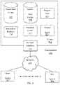
- FIG. 3illustrates a block diagram of an example of an environment wherein an on-demand database service might be used
- FIG. 4illustrates a block diagram of an embodiment of elements of FIG. 3 and various possible interconnections between these elements.
- a systemcreates a graph of nodes connected by edges. Each node represents a corresponding value of a corresponding attribute and is associated with a count of the corresponding value. Each edge is associated with a count of instances that values represented by corresponding connected nodes are associated with each other.
- the systemidentifies each node associated with a first count as a first set of keys, and deletes each node associated with the first count.
- the systemidentifies each edge associated with a second count as a second set of keys, and deletes each edge associated with the second count.
- the systemidentifies each node associated with a third count as a third set of keys, and deletes each node associated with the third count.
- the systemidentifies each edge associated with a fourth count as a fourth set of keys, and deletes each edge associated with the fourth count.
- the systemuses each set of keys to search and match records.
- a customer resolution enginecreates the graph depicted by FIG. 1A .
- One noderepresents “Bob” as Bob Brown's given name, and has the weight of 2, which is the number of times that Bob Brown entered his given name when visiting a MegaCorp website.
- One edgehas the weight of 4, which is the number of times that Ann Adams entered her name when visiting a MegaCorp website.
- the customer resolution engineidentifies the node representing Bob Brown's email address as the match key ⁇ bbrown@acme.com ⁇ because this node has the weight of 1, and then deletes this node and its edges.
- the customer resolution engineidentifies the edge connecting the node representing Bob Brown's given name with the node representing Acme's main phone number as the match key ⁇ Bob, 1-987-654-3210 ⁇ and the edge connecting the node representing Bob Brown's family name with the node representing Acme's main phone number as the match key ⁇ Brown, 1-987-654-3210 ⁇ because these edges have the weight of 1, and then deletes these edges.
- the customer resolution engineidentifies the node representing Ann Adams' email address as the match key ⁇ aadams@acme.com ⁇ , Bob Brown's given name as the match key ⁇ Bob ⁇ , and Bob Brown's family name as the match key ⁇ Brown ⁇ because these nodes have the weight of 2, and then deletes these nodes.
- the customer resolution engineidentifies the edge connecting the node representing Ann Adams' given name with the node representing Acme's main phone number as the match key ⁇ Ann, 1-987-654-3210 ⁇ and the edge connecting the node representing Ann Adams' family name with the node representing Acme's main phone number as the match key ⁇ Adams, 1-987-654-3210 ⁇ because these edges have the weight of 2, and then deletes these edges.
- the customer resolution enginecan identify the node representing Acme's main phone number as the match key ⁇ 1-987-654-3210 ⁇ because this node has the weight of 3, and then delete this node.
- the customer resolution enginecan identify the node representing Ann Adams's given name as the match key ⁇ Ann ⁇ and the node representing Ann Adams's family name as the match key ⁇ Adams ⁇ because these nodes have the weight of 4, and then deletes these nodes and their edge.
- the customer resolution engineuses only the match key ⁇ bbrown@acme.com ⁇ of the match keys ⁇ bbrown@acme.com ⁇ , ⁇ Bob, 1-987-654-3210 ⁇ , ⁇ Brown, 1-987-654-3210 ⁇ , ⁇ aadams@acme.com ⁇ , ⁇ Bob ⁇ , ⁇ Brown ⁇ , ⁇ Ann, 1-987-654-3210 ⁇ , ⁇ Adams, 1-987-654-3210 ⁇ , ⁇ 1-987-654-3210 ⁇ , ⁇ Ann ⁇ , and ⁇ Adams ⁇ to efficiently search and match MegaCorp's existing records for Bob Brown when Bob Brown enters his name and email address when visiting MegaCorp's customer service website.
- the customer resolution enginegenerates match keys that have a near-perfect recall (they almost never miss any matches) while being orders of magnitude faster than a naive approach that would deep-match all pairs of database records.
- the term multi-tenant database systemrefers to those systems in which various elements of hardware and software of the database system may be shared by one or more customers. For example, a given application server may simultaneously process requests for a great number of customers, and a given database table may store rows for a potentially much greater number of customers.
- the term query planrefers to a set of steps used to access information in a database system. The following detailed description will first describe a data structure for generating adaptive match keys. Next, methods and systems for generating adaptive match keys will be described with reference to example embodiments.
- While one or more implementations and techniquesare described with reference to an embodiment in which generating adaptive match keys is implemented in a system having an application server providing a front end for an on-demand database service capable of supporting multiple tenants, the one or more implementations and techniques are not limited to multi-tenant databases nor deployment on application servers. Embodiments may be practiced using other database architectures, i.e., ORACLE®, DB2® by IBM and the like without departing from the scope of the embodiments claimed.
- any of the embodiments described hereinmay be used alone or together with one another in any combination.
- the one or more implementations encompassed within this specificationmay also include embodiments that are only partially mentioned or alluded to or are not mentioned or alluded to at all in this brief summary or in the abstract.
- a customer resolution enginecan cleanse, normalize, and enrich customer data as needed. For example, a traditional match rule for uniquely identifying a person may process the data set that includes “John Smith/1 Main St, San Francisco, Calif. 94105” and “John Smith/11 Main St, San Francisco, Calif. 94105,” and identify two unique people. While a traditional match rule can match addresses by using “fuzzy” strings, in isolation this fuzzy matching can lead to false positives, as there could be two different John Smiths at different addresses.
- the customer resolution enginecan more intelligently apply matching rules by incorporating customer data reliability into the matching process. For this example, the customer resolution engine captures and leverages data validation and enrichment attributes as part of the attributes to determine that “11 Main St” is not a valid street address for “San Francisco, Calif. 94105,” infer a data entry error in the street number, and then identify the nearest string or geo-proximity match as a reliable candidate, thereby identifying only one unique John Smith on Main Street in San Francisco.
- the customer resolution enginecan use a similar approach in assessing reliability of an attribute value for uniqueness. For example, a traditional match rule “Name AND (Phone Number OR Email)” would process the data set that includes “John Smith/415-555-1212/john.smith@gmail.com,” “John Smith/415-555-1212/john smith@gmail.com,” and “Cary Jones/415-555-1212/cary@joneses.com,” and then identify two unique people, John Smith and Cary Jones. In contrast, the customer resolution engine can more intelligently apply matching rules by identifying how many unique source records, names, and email addresses relate to any given phone number, or vice versa.
- the customer resolution enginecan apply a matching rule that processes the specific phone number as a shared attribute value, which is not a unique attribute value, thereby identifying two unique John Smiths who share the phone number 415-555-1212.
- the customer resolution engineprocesses database records that have n attributes, referred to as X 1 , X 2 , . . . X n , with each attribute having its own discrete set of values referred to as V 1 , V 2 , . . . V n .
- attributesinclude first_name, last_name, phone number, and city. Numeric attributes are assumed to have been suitably discretized.
- the customer resolution enginegenerates an n-partite graph whose nodes partition into V 1 , V 2 , . . . V n , where V i denotes the set of values of attribute X i .
- the customer resolution enginedoes not connect nodes in the same part by an edge, due to the constraint that in any given database record and for any i, X i takes on at most one value from V i . X i may not take on any value in a given database record.
- the weight on node vis the number of database records in a given set S that contain the attribute: value pair associated with the node v.
- the weight on edge ⁇ u, v ⁇is the number of database records in S that contain the attribute: value pair associated with both of the nodes u and v.
- the customer resolution enginecan efficiently compute the weights on all the nodes and the edges of the graph in one pass over the data set. When the customer resolution engine encounters a new database record, the customer resolution engine increments by 1 the weights of the nodes and edges that correspond to the new database record.
- a cliquecan be a set of one or more nodes where each pair of nodes is connected by an edge.
- a clique's weightcan be the sum of the weights of the nodes and the edges in the clique.
- FIGS. 1A-Ddepict graphs that the customer resolution engine generates based on the following example database records.
- the customer resolution enginegenerates the graph 100 based on these six database records, as depicted by FIG. 1A .
- the graph 100includes nodes representing attribute values and edges connecting the nodes, with each edge representing a number of instances that one connected node's attribute value is associated with the other connected node's attribute value.
- the graph 100includes the given name node 102 that represents the attribute value “Ann,” the family name node 104 that represents the attribute value “Adams,” the phone node 106 that represents the attribute value “1-987-654-3210,” and the email node 108 that represents the attribute value “aadams@acme.com.”
- the graph 100also includes the given name node 110 that represents the attribute value “Bob,” the family name node 112 that represents the attribute value “Brown,” and the email node 114 that represents the attribute value “bbrwon@acme.com.”
- the weight of 4 for the node 102represents the 4 instances that “Ann” is stored by the 6 database records
- the weight of 4 for the node 104represents the 4 instances that “Adams” is stored by the 6 database records
- the weight of 3 for the node 106represents the 3 instances that “1-987-654-3210” is stored by the 6 database records
- the weight of 2 for the node 108represents the 2 instances that “aadams@acme.com” is stored by the 6 database records.
- the weight of 2 for the node 110represents the 2 instances that “Bob” is stored by the 6 database records
- the weight of 2 for the node 112represents the 2 instances that “Brown” is stored by the 6 database records
- the weight of 1 for the node 114represents the 1 instance that “bbrown@acme.com” is stored by the 6 database records.
- the edge 116connects the nodes 102 and 104 , and has a weight of 4 that represents the 4 instances of “Ann” and “Adams” being stored together in the 6 database records; the edge 118 connects the nodes 102 and 106 , and has a weight of 2 that represents the 2 instances of “Ann” and “1-987-654-3210” being stored together in the 6 database records, and the edge 120 connects the nodes 104 and 106 , and has a weight of 2 that represents the 2 instances of “Adams” and “1-987-654-3210” being stored together in the 6 database records.
- the edge 122connects the nodes 102 and 108 , and has a weight of 2 that represents the 2 instances of “Ann” and “aadams @ acme.com” being stored together in the 6 database records; and the edge 124 connects the nodes 104 and 108 , and has a weight of 2 that represents the 2 instances of “Adams” and “aadams@acme.com” being stored together in the 6 database records.
- the edge 126connects the nodes 110 and 112 , and has a weight of 2 that represents the 2 instances of “Bob” and “Brown” being stored together in the 6 database records; the edge 128 connects the nodes 110 and 106 , and has a weight of 1 that represents the 1 instance of “Bob” and “1-987-654-3210” being stored together in the 6 database records, and the edge 130 connects the nodes 112 and 106 , and has a weight of 1 that represents the 1 instance of “Brown” and “1-987-654-3210” being stored together in the 6 database records.
- the edge 132connects the nodes 110 and 114 , and has a weight of 1 that represents the 1 instance of “Bob” and “bbrown@acme.com” being stored together in the 6 database records; and the edge 134 connects the nodes 112 and 114 , and has a weight of 1 that represents the 1 instances of “Brown” and “bbrown@acme.com” being stored together in the 6 database records.
- the graph 100depicts nodes, edges, and weights for only four attributes (given name, family name, email, and phone) based on only six database records
- the customer resolution enginecan generate a graph that depicts nodes, edges, and weights for any number of attributes based on any number of database records.
- Clustering analysiscan be run on the graph to discover clusters of nodes which can be grouped together as a clique. These nodes can further be refined and analyzed to distill a master profile, which may be referred to as an entity 360 view, that can then be used for a number of business use cases. Any attribute value may be shared by multiple cliques. However, sharing, in general, is constrained to fairly tight social groups, such as a household, a company, roommates, etc. Since the main use case is to connect an attribute value to a small number of master profiles, any attribute value that has a high number of edges may be handled differently, such as by being removed from the graph. Consequently, the graph is a collection of many smaller cliques.
- the graphmay be an undirected, weighted, and colored data structure.
- the graphmay be “undirected” because there is no directionality of the edges that represent relationships. All that is known is that attribute value A is connected to attribute value B, such as the given name “Ann” is connected to the family name “Adams.”
- the graphmay be “weighted” because some relationships between attribute values are stronger than other relationships between attribute values. For example, if the same email address and the same phone number are connected together by data from multiple sources, instead of adding multiple edges, the weight of the edge connecting the phone number and the email address is incremented. This weighting provides useful meta data for clustering algorithms.
- the graphmay be “colored” because not all edges may be the same, as different edges may represent different types of relationships.
- one edgemay represent a business relationship, such as an edge that connects a customer's name to the customer's business email address, and another edge may represent a personal relationship, such as an edge that connects the customer's name to the customer's personal email address.
- Colored edgesrepresent useful metadata for clustering and for constructing master profiles.
- the customer resolution engineSince a set of one or more nodes represents a set of attributes taking on unique values from their value sets, the customer resolution engine generates each match key from a corresponding set of one or more nodes that forms a corresponding clique.
- the clique constraintincreases the likelihood that the values go together, such that the values are not mutually incompatible.
- the customer resolution enginefavors smaller cliques over larger cliques because the smaller the clique, the fewer the attributes whose values are constrained, hence the higher its recall, which is the number of records found by a lookup on a match key.
- the customer resolution enginemay have no choice but to use small cliques as match keys.
- the customer resolution enginefavors using lower-weight cliques, which is similar to “cherry-picking,” over higher-weight cliques because using higher-weight cliques risks having too many records, which is not performant.
- the customer resolution engineOnce the customer resolution engine had identified a specific clique to be a match key, the customer resolution engine will discard all cliques that are proper supersets of the identified clique as candidates for being match keys because proper supersets of good match keys are redundant. A clique that has already been identified as a match key meets the necessary condition, such that a super set key can only have lower recall.
- the customer resolution engine's algorithminputs a support parameter W:
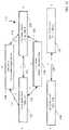
- FIG. 2is an operational flow diagram illustrating a high-level overview of a method 200 for generating adaptive match keys.
- a graph of nodes connected by edgesis created, wherein each node represents a corresponding value of a corresponding attribute and is associated with a count of the corresponding value, and each edge is associated with a count of instances that values represented by corresponding connected nodes are associated with each other, block 202 .
- the database systemcreates a graph of cliques that will be identified as matching keys. For example, and without limitation, this can include a customer resolution engine generating the graph 100 depicted by FIG.
- the graph 100is a 4-partite graph because the graph 100 represents values for the 4 attributes given name, family name, phone, and email, such that the algorithm variable n equals 4.
- a graphcan be a diagram showing the relation between variable quantities.
- a nodecan be a point at which lines or pathways intersect or branch; a central or connecting point.
- An edgecan be a line extending from one node to another node.
- a valuecan be a symbol on which operations are performed by a computer.
- An attributecan be a piece of information that determines the properties of a field in a database.
- a countcan be an arithmetical value, expressed by a word, symbol, or figure, representing a particular quantity and used in making calculations. An instance can be an example or single occurrence of something.
- a connected nodecan be a point at which lines or pathways intersect or branch.
- each node associated with a first countis identified as a first set of keys, block 204 .
- the database systemidentifies each single node clique with the weight of one as a match key.
- thiscan include the customer resolution engine identifying the node 114 with the weight of 1 as the match key ⁇ bbrown@acme.com ⁇ .
- a setcan be zero or more things that belong or are used together.
- a keycan be at least one field in a record that is used to lookup the record.
- the customer resolution enginefavors smaller cliques over larger cliques and favors lower-weight cliques over higher-weight cliques.
- the algorithm variable kequals 1 and the algorithm variable W equals 1.
- each node associated with the first countis deleted, block 206 .
- the database systemdeletes each one-node clique that was identified as a match key. In embodiments, this can include the customer resolution engine deleting the node 114 , which also deletes the edges 132 and 134 that connect the node 114 to other nodes, from the graph 100 depicted by FIG. 1A , thereby creating the graph 136 depicted by FIG. 1B .
- the customer resolution enginediscards all cliques that are proper supersets of the node 114 as candidates for being match keys.
- each edge associated with a second countis identified as a second set of keys, block 208 .
- the database systemidentifies each double node clique connected by an edge with the weight of one as a match key. For example, and without limitation, this can include the customer resolution engine identifying the edge 128 that has a weight of 1 and connects the nodes 110 and 106 as the match key ⁇ Bob, 1-987-654-3210 ⁇ , and the edge 130 that has a weight of 1 and connects the nodes 112 and 106 as the match key ⁇ Brown, 1-987-654-3210 ⁇ , as depicted by FIG. 1B .
- the customer resolution enginewould have identified the edges 132 and 134 that have the weights of 1 as match keys, as depicted by FIG. 1A , but the customer resolution engine already deleted the edges 132 and 134 when deleting the node 114 that was identified as a match key, such that the edges 132 and 134 are absent from the graph 136 depicted by FIG. 1B .
- the customer resolution enginefavors smaller cliques over larger cliques and favors lower-weight cliques over higher-weight cliques.
- the algorithm variable kequals 2 and the algorithm variable W equals 1.
- the second countis at least the first count. For example, the second count and the first count both have the value of 1.
- each edge associated with the second countis deleted, block 210 .
- the database systemdeletes each edge that was identified as a match key.
- thiscan include the customer resolution engine deleting the edges 128 and 130 from the graph 136 depicted by FIG. 1B . Consequently, the customer resolution engine's deletions create the graph 138 depicted by FIG. 1C .
- the customer resolution enginediscards all cliques that are proper supersets of the edges 128 and 130 as candidates for being match keys.
- each node associated with a third countis identified as a third set of keys, block 212 .
- the database systemidentifies each single node clique with the weight of two as a match key. In embodiments, this can include a customer resolution engine identifying the node 108 as the match key ⁇ aadams@acme.com ⁇ , the node 110 as the match key ⁇ Bob ⁇ , and the node 112 as the match key ⁇ Brown ⁇ .
- the customer resolution enginefavors smaller cliques over larger cliques and favors lower-weight cliques over higher-weight cliques.
- the algorithm variable kequals 1 and the algorithm variable W equals 2.
- the third countis at least the second count. For example, the third count equals 2 and the second count equals 1.
- each node associated with the third countis deleted, block 214 .
- the database systemdeletes each one-node clique that was identified as a match key. For example, and without limitation, this can include the customer resolution engine deleting the nodes 108 , 110 , and 112 , which also deletes the edges 122 and 124 that connect the node 108 to other nodes, and the edge 126 that connects the nodes 110 and 112 , from the graph 138 depicted by FIG. 1C , thereby creating the graph 140 depicted by FIG. 1D .
- the customer resolution engineBy deleting the cliques that are the nodes 108 , 110 , and 112 which were identified as match keys, the customer resolution engine discards all cliques that are proper supersets of the node 108 , 110 , and 112 as candidates for being match keys.
- each edge associated with a fourth countis identified as a fourth set of keys, block 216 .
- the database systemidentifies each double node clique connected by an edge with the weight of 2 as a match key. By way of example and without limitation, this includes the customer resolution engine identifying the edge 118 that has a weight of 2 and connects the nodes 102 and 106 as the match key ⁇ Ann, 1-987-654-3210 ⁇ , and the edge 120 that has a weight of 2 and connects the nodes 104 and 106 as the match key ⁇ Adams, 1-987-654-3210 ⁇ .
- the algorithm variable kequals 2 and the algorithm variable W equals 2.
- the fourth countis at least the third count. For example, the fourth count equals 2 and the third count equals 2.
- each edge associated with the fourth countis deleted, block 218 .
- the database systemdeletes each edge that was identified as a match key. In embodiments, this includes the customer resolution engine deleting the edges 118 and 120 from the graph 140 depicted by FIG. 1D , thereby creating the graph 142 depicted by FIG. 1E . By deleting the edges 118 and 120 which were identified as match keys, the customer resolution engine discards all cliques that are proper supersets of the edges 118 and 120 as candidates for being match keys.
- each pair of edges connected by a corresponding node and collectively associated with a fifth countare optionally identified as a fifth set of keys, block 220 .
- the database systemcan identify each pair of edges that are connected by a node and that have a weight of 2 as a match key. For example, and without limitation, this could have included the customer resolution engine identifying the edges 132 and 134 that are connected by the node 114 , which are a clique with the edge weights of 2, as the match key ⁇ Bob, bbrown@acme.com, Brown ⁇ if the customer resolution engine had not already deleted these edges 132 and 134 and the node 114 .
- the algorithm variable kequals 3 and the algorithm variable W equals 2.
- each pair of edges connected by the corresponding node and collectively associated with the fifth countare optionally deleted, block 222 .
- the database systemdeletes each edge that was identified as a match key. By way of example and without limitation, this could have included the customer resolution engine deleting the edges 132 and 134 that are connected by the node 114 , if the customer resolution engine had not already deleted these edges 132 and 134 .
- each node associated with a sixth countis optionally identified as a sixth set of keys, block 224 .
- the database systemidentifies each single node clique with the weight of 3 as a match key. In embodiments, this includes a customer resolution engine identifying the node 106 that has a weight of 3 as the match key ⁇ 1-987-654-3210 ⁇ .
- the algorithm variable kequals 1 and the algorithm variable W equals 3.
- the sixth countis at least the fifth count. For example, the sixth count equals 3 and the fifth count equals 2.
- each node associated with the sixth countis optionally deleted, block 226 .
- the database systemdeletes each one-node clique that was identified as a match key. For example, and without limitation, this could have included the customer resolution engine deleting the node 106 from the graph 142 depicted by FIG. 1E , thereby creating the graph 144 depicted by FIG. 1F .
- each edge associated with a seventh countis optionally identified as a seventh set of keys, block 228 .
- the database systemidentifies each double node clique connected by an edge with the weight of 3 as a match key.
- thiscould have included the customer resolution engine identifying the edge 116 that connects the nodes 102 and 104 as the match key ⁇ Ann, Adams ⁇ , as depicted by FIG. 1F , if edge 116 that connects the nodes 102 and 104 had the weight of 3.
- the algorithm variable kequals 2 and the algorithm variable W equals 3.
- the seventh countis at least the sixth count. For example, the seventh count equals 3 and the sixth count equals 3.
- each edge associated with the seventh countis optionally deleted, block 230 .
- the database systemdeletes each edge that was identified as a match key. In embodiments, this could have included the customer resolution engine deleting the edge 116 from the graph 144 depicted by FIG. 1F , if the edge 116 that connects the nodes 102 and 104 had the weight of 3.
- each pair of edges connected by a corresponding node and collectively associated with an eighth countis optionally identified as an eighth set of keys, block 232 .
- the database systemcan identify each pair of edges that are connected by a node and that have a specified weight as a match key. For example, and without limitation, this could have included the customer resolution engine identifying the edges 118 and 120 that are connected by the node 106 , which is a clique with the edge weights of 4, as the match key ⁇ Ann, 1-987-654-3210, Adams ⁇ , if the these edges 118 and 120 that connect the node 106 had the weight of 3.
- the algorithm variable kequals 3 and the algorithm variable W equals 3.
- the eighth countis at least the seventh count. For example, the eighth count equals 3 and the seventh count equals 3.
- each pair of edges connected by a corresponding node and collectively associated with the eighth countis optionally deleted, block 234 .
- the database systemdeletes each edge that was identified as a match key. By way of example and without limitation, this could have included the customer resolution engine deleting the edges 118 and 120 that are connected by the node 106 , if edges 118 and 120 had the weight of 3.
- the identification of match keyscan continue with cliques that have any number of nodes and weights or counts of any number.
- the customer resolution engineidentifies the node 102 that has a weight of 4 as the match key ⁇ Ann ⁇ and the node 104 that has a weight of 4 as the match key ⁇ Adams ⁇ .
- the algorithm variable kequals 1
- the algorithm variable Wequals 4.
- the customer resolution enginedeletes the nodes 102 and 104 from the graph 144 depicted by FIG. 1F , which also deletes the edge 116 that connects the nodes 102 and 104 , such that the match key generation is completed because the graph 144 is empty.
- each set of keysis used to search and match records, block 236 .
- the database systemuses the match keys to identify existing database records that match a newly received database record. In embodiments, this can include the customer resolution engine using only the match key ⁇ bbrown@acme.com ⁇ of the match keys ⁇ bbrown@acme.com ⁇ , ⁇ Bob, 1-987-654-3210 ⁇ , ⁇ Brown, 1-987-654-3210 ⁇ , ⁇ aadams@acme.com ⁇ , ⁇ Bob ⁇ , ⁇ Brown ⁇ , ⁇ Ann, 1-987-654-3210 ⁇ , ⁇ Adams, 1-987-654-3210 ⁇ , ⁇ 1-987-654-3210 ⁇ , ⁇ Ann ⁇ , and ⁇ Adams ⁇ to efficiently search and match MegaCorp's existing records for Bob Brown when Bob Brown enters his name and email address when visiting MegaCorp's customer service website.
- the customer resolution enginefavors smaller cliques over larger cliques and favors lower-weight cliques over higher-weight cliques.
- the customer resolution enginegenerates match keys that have a near-perfect recall (they almost never miss any matches) while being orders of magnitude faster than a naive approach that would deep-match all pairs of database records.
- a recordcan be the storage of at least one value in a persistent form.
- the method 200may be repeated as desired.
- this disclosuredescribes the blocks 202 - 236 executing in a particular order, the blocks 202 - 236 may be executed in a different order. In other implementations, each of the blocks 202 - 236 may also be executed in combination with other blocks and/or some blocks may be divided into a different set of blocks.
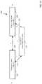
- FIG. 3illustrates a block diagram of an environment 310 wherein an on-demand database service might be used.
- the environment 310may include user systems 312 , a network 314 , a system 316 , a processor system 317 , an application platform 318 , a network interface 320 , a tenant data storage 322 , a system data storage 324 , program code 326 , and a process space 328 .
- the environment 310may not have all of the components listed and/or may have other elements instead of, or in addition to, those listed above.
- the environment 310is an environment in which an on-demand database service exists.
- a user system 312may be any machine or system that is used by a user to access a database user system.
- any of the user systems 312may be a handheld computing device, a mobile phone, a laptop computer, a work station, and/or a network of computing devices.
- the user systems 312might interact via the network 314 with an on-demand database service, which is the system 316 .
- An on-demand database servicesuch as the system 316
- Some on-demand database servicesmay store information from one or more tenants stored into tables of a common database image to form a multi-tenant database system (MTS).
- MTSmulti-tenant database system
- the “on-demand database service 316 ” and the “system 316 ”will be used interchangeably herein.
- a database imagemay include one or more database objects.
- a relational database management system (RDMS) or the equivalentmay execute storage and retrieval of information against the database object(s).
- RDMSrelational database management system
- the application platform 318may be a framework that allows the applications of the system 316 to run, such as the hardware and/or software, e.g., the operating system.
- the on-demand database service 316may include the application platform 318 which enables creation, managing and executing one or more applications developed by the provider of the on-demand database service, users accessing the on-demand database service via user systems 312 , or third-party application developers accessing the on-demand database service via the user systems 312 .
- the users of the user systems 312may differ in their respective capacities, and the capacity of a particular user system 312 might be entirely determined by permissions (permission levels) for the current user. For example, where a salesperson is using a particular user system 312 to interact with the system 316 , that user system 312 has the capacities allotted to that salesperson. However, while an administrator is using that user system 312 to interact with the system 316 , that user system 312 has the capacities allotted to that administrator. In systems with a hierarchical role model, users at one permission level may have access to applications, data, and database information accessible by a lower permission level user, but may not have access to certain applications, database information, and data accessible by a user at a higher permission level. Thus, different users will have different capabilities with regard to accessing and modifying application and database information, depending on a user's security or permission level.
- the network 314is any network or combination of networks of devices that communicate with one another.
- the network 314may be any one or any combination of a LAN (local area network), WAN (wide area network), telephone network, wireless network, point-to-point network, star network, token ring network, hub network, or other appropriate configuration.
- LANlocal area network
- WANwide area network
- telephone networkwireless network
- point-to-point networkstar network
- token ring networktoken ring network
- hub networkor other appropriate configuration.
- TCP/IPTransfer Control Protocol and Internet Protocol
- the user systems 312might communicate with the system 316 using TCP/IP and, at a higher network level, use other common Internet protocols to communicate, such as HTTP, FTP, AFS, WAP, etc.
- HTTPHyperText Transfer Protocol
- the user systems 312might include an HTTP client commonly referred to as a “browser” for sending and receiving HTTP messages to and from an HTTP server at the system 316 .
- HTTP servermight be implemented as the sole network interface between the system 316 and the network 314 , but other techniques might be used as well or instead.
- the interface between the system 316 and the network 314includes load sharing functionality, such as round-robin HTTP request distributors to balance loads and distribute incoming HTTP requests evenly over a plurality of servers. At least as for the users that are accessing that server, each of the plurality of servers has access to the MTS' data; however, other alternative configurations may be used instead.
- the system 316implements a web-based customer relationship management (CRM) system.
- the system 316includes application servers configured to implement and execute CRM software applications as well as provide related data, code, forms, webpages and other information to and from the user systems 312 and to store to, and retrieve from, a database system related data, objects, and Webpage content.
- CRMcustomer relationship management
- data for multiple tenantsmay be stored in the same physical database object, however, tenant data typically is arranged so that data of one tenant is kept logically separate from that of other tenants so that one tenant does not have access to another tenant's data, unless such data is expressly shared.
- the system 316implements applications other than, or in addition to, a CRM application.
- the system 316may provide tenant access to multiple hosted (standard and custom) applications, including a CRM application.
- User (or third-party developer) applicationswhich may or may not include CRM, may be supported by the application platform 318 , which manages creation, storage of the applications into one or more database objects and executing of the applications in a virtual machine in the process space of the system 316 .
- FIG. 3One arrangement for elements of the system 316 is shown in FIG. 3 , including the network interface 320 , the application platform 318 , the tenant data storage 322 for tenant data 323 , the system data storage 324 for system data 325 accessible to the system 316 and possibly multiple tenants, the program code 326 for implementing various functions of the system 316 , and the process space 328 for executing MTS system processes and tenant-specific processes, such as running applications as part of an application hosting service. Additional processes that may execute on the system 316 include database indexing processes.
- each of the user systems 312could include a desktop personal computer, workstation, laptop, PDA, cell phone, or any wireless access protocol (WAP) enabled device or any other computing device capable of interfacing directly or indirectly to the Internet or other network connection.
- WAPwireless access protocol
- Each of the user systems 312typically runs an HTTP client, e.g., a browsing program, such as Microsoft's Internet Explorer browser, Netscape's Navigator browser, Opera's browser, or a WAP-enabled browser in the case of a cell phone, PDA or other wireless device, or the like, allowing a user (e.g., subscriber of the multi-tenant database system) of the user systems 312 to access, process and view information, pages and applications available to it from the system 316 over the network 314 .
- a browsing programsuch as Microsoft's Internet Explorer browser, Netscape's Navigator browser, Opera's browser, or a WAP-enabled browser in the case of a cell phone, PDA or other wireless device, or the like.
- Each of the user systems 312also typically includes one or more user interface devices, such as a keyboard, a mouse, trackball, touch pad, touch screen, pen or the like, for interacting with a graphical user interface (GUI) provided by the browser on a display (e.g., a monitor screen, LCD display, etc.) in conjunction with pages, forms, applications and other information provided by the system 316 or other systems or servers.
- GUIgraphical user interface
- the user interface devicemay be used to access data and applications hosted by the system 316 , and to perform searches on stored data, and otherwise allow a user to interact with various GUI pages that may be presented to a user.
- embodimentsare suitable for use with the Internet, which refers to a specific global internetwork of networks. However, it should be understood that other networks may be used instead of the Internet, such as an intranet, an extranet, a virtual private network (VPN), a non-TCP/IP based network, any LAN or WAN or the like.
- VPNvirtual private network
- each of the user systems 312 and all of its componentsare operator configurable using applications, such as a browser, including computer code run using a central processing unit such as an Intel Pentium® processor or the like.
- applicationssuch as a browser, including computer code run using a central processing unit such as an Intel Pentium® processor or the like.
- the system 316 (and additional instances of an MTS, where more than one is present) and all of their componentsmight be operator configurable using application(s) including computer code to run using a central processing unit such as the processor system 317 , which may include an Intel Pentium® processor or the like, and/or multiple processor units.
- a computer program product embodimentincludes a machine-readable storage medium (media) having instructions stored thereon/in which may be used to program a computer to perform any of the processes of the embodiments described herein.
- Computer code for operating and configuring the system 316 to intercommunicate and to process webpages, applications and other data and media content as described hereinare preferably downloaded and stored on a hard disk, but the entire program code, or portions thereof, may also be stored in any other volatile or non-volatile memory medium or device as is well known, such as a ROM or RAM, or provided on any media capable of storing program code, such as any type of rotating media including floppy disks, optical discs, digital versatile disk (DVD), compact disk (CD), micro-drive, and magneto-optical disks, and magnetic or optical cards, Nano-systems (including molecular memory ICs), or any type of media or device suitable for storing instructions and/or data.
- any other volatile or non-volatile memory medium or devicesuch as a ROM or RAM
- any media capable of storing program codesuch as any type of rotating media including floppy disks, optical discs, digital versatile disk (DVD), compact disk (CD), micro-drive, and magneto-optical disks
- the entire program code, or portions thereofmay be transmitted and downloaded from a software source over a transmission medium, e.g., over the Internet, or from another server, as is well known, or transmitted over any other conventional network connection as is well known (e.g., extranet, VPN, LAN, etc.) using any communication medium and protocols (e.g., TCP/IP, HTTP, HTTPS, Ethernet, etc.) as are well known.
- a transmission mediume.g., over the Internet
- any other conventional network connectione.g., extranet, VPN, LAN, etc.
- any communication medium and protocolse.g., TCP/IP, HTTP, HTTPS, Ethernet, etc.
- computer code for implementing embodimentsmay be implemented in any programming language that may be executed on a client system and/or server or server system such as, for example, C, C++, HTML, any other markup language, JavaTM, JavaScript, ActiveX, any other scripting language, such as VBScript, and many other programming languages as are well known may be used.
- JavaTMis a trademark of Sun Microsystems, Inc.
- the system 316is configured to provide webpages, forms, applications, data and media content to the user (client) systems 312 to support the access by the user systems 312 as tenants of the system 316 .
- the system 316provides security mechanisms to keep each tenant's data separate unless the data is shared.
- MTSMobility Management Entity
- theymay be located in close proximity to one another (e.g., in a server farm located in a single building or campus), or they may be distributed at locations remote from one another (e.g., one or more servers located in city A and one or more servers located in city B).
- each MTScould include one or more logically and/or physically connected servers distributed locally or across one or more geographic locations.
- serveris meant to include a computer system, including processing hardware and process space(s), and an associated storage system and database application (e.g., OODBMS or RDBMS) as is well known in the art. It should also be understood that “server system” and “server” are often used interchangeably herein.
- database object described hereinmay be implemented as single databases, a distributed database, a collection of distributed databases, a database with redundant online or offline backups or other redundancies, etc., and might include a distributed database or storage network and associated processing intelligence.
- FIG. 4also illustrates the environment 310 . However, in FIG. 4 elements of the system 316 and various interconnections in an embodiment are further illustrated.
- FIG. 4shows that the each of the user systems 312 may include a processor system 312 A, a memory system 312 B, an input system 312 C, and an output system 312 D.
- FIG. 4shows the network 314 and the system 316 .
- system 316may include the tenant data storage 322 , the tenant data 323 , the system data storage 324 , the system data 325 , a User Interface (UI) 430 , an Application Program Interface (API) 432 , a PL/SOQL 434 , save routines 436 , an application setup mechanism 438 , applications servers 400 1 - 400 N , a system process space 402 , tenant process spaces 404 , a tenant management process space 410 , a tenant storage area 412 , a user storage 414 , and application metadata 416 .
- the environment 310may not have the same elements as those listed above and/or may have other elements instead of, or in addition to, those listed above.
- the processor system 312 Amay be any combination of one or more processors.
- the memory system 312 Bmay be any combination of one or more memory devices, short term, and/or long-term memory.
- the input system 312 Cmay be any combination of input devices, such as one or more keyboards, mice, trackballs, scanners, cameras, and/or interfaces to networks.
- the output system 312 Dmay be any combination of output devices, such as one or more monitors, printers, and/or interfaces to networks. As shown by FIG.
- the system 316may include the network interface 320 (of FIG. 3 ) implemented as a set of HTTP application servers 400 , the application platform 318 , the tenant data storage 322 , and the system data storage 324 . Also shown is the system process space 402 , including individual tenant process spaces 404 and the tenant management process space 410 .
- Each application server 400may be configured to access tenant data storage 322 and the tenant data 323 therein, and the system data storage 324 and the system data 325 therein to serve requests of the user systems 312 .
- the tenant data 323might be divided into individual tenant storage areas 412 , which may be either a physical arrangement and/or a logical arrangement of data.
- each tenant storage area 412the user storage 414 and the application metadata 416 might be similarly allocated for each user. For example, a copy of a user's most recently used (MRU) items might be stored to the user storage 414 . Similarly, a copy of MRU items for an entire organization that is a tenant might be stored to the tenant storage area 412 .
- the UI 430provides a user interface and the API 432 provides an application programmer interface to the system 316 resident processes to users and/or developers at the user systems 312 .
- the tenant data and the system datamay be stored in various databases, such as one or more OracleTM databases.
- the application platform 318includes the application setup mechanism 438 that supports application developers' creation and management of applications, which may be saved as metadata into the tenant data storage 322 by the save routines 436 for execution by subscribers as one or more tenant process spaces 404 managed by the tenant management process 410 for example. Invocations to such applications may be coded using the PL/SOQL 434 that provides a programming language style interface extension to the API 432 . A detailed description of some PL/SOQL language embodiments is discussed in commonly owned U.S. Pat. No. 7,730,478 entitled, METHOD AND SYSTEM FOR ALLOWING ACCESS TO DEVELOPED APPLICATIONS VIA A MULTI-TENANT ON-DEMAND DATABASE SERVICE, by Craig Weissman, filed Sep. 21, 2007, which is incorporated in its entirety herein for all purposes. Invocations to applications may be detected by one or more system processes, which manages retrieving the application metadata 416 for the subscriber making the invocation and executing the metadata as an application in a virtual machine.
- Each application server 400may be communicably coupled to database systems, e.g., having access to the system data 325 and the tenant data 323 , via a different network connection.
- database systemse.g., having access to the system data 325 and the tenant data 323 , via a different network connection.
- one application server 400 1might be coupled via the network 314 (e.g., the Internet)
- another application server 400 N-1might be coupled via a direct network link
- another application server 400 Nmight be coupled by yet a different network connection.
- Transfer Control Protocol and Internet ProtocolTCP/IP
- TCP/IPTransfer Control Protocol and Internet Protocol
- each application server 400is configured to handle requests for any user associated with any organization that is a tenant. Because it is desirable to be able to add and remove application servers from the server pool at any time for any reason, there is preferably no server affinity for a user and/or organization to a specific application server 400 .
- an interface system implementing a load balancing functione.g., an F5 Big-IP load balancer
- the load balanceruses a least connections algorithm to route user requests to the application servers 400 .
- Other examples of load balancing algorithmssuch as round robin and observed response time, also may be used.
- the system 316is multi-tenant, wherein the system 316 handles storage of, and access to, different objects, data and applications across disparate users and organizations.
- one tenantmight be a company that employs a sales force where each salesperson uses the system 316 to manage their sales process.
- a usermight maintain contact data, leads data, customer follow-up data, performance data, goals and progress data, etc., all applicable to that user's personal sales process (e.g., in the tenant data storage 322 ).
- the usersince all of the data and the applications to access, view, modify, report, transmit, calculate, etc., may be maintained and accessed by a user system having nothing more than network access, the user can manage his or her sales efforts and cycles from any of many different user systems. For example, if a salesperson is visiting a customer and the customer has Internet access in their lobby, the salesperson can obtain critical updates as to that customer while waiting for the customer to arrive in the lobby.
- the user systems 312(which may be client systems) communicate with the application servers 400 to request and update system-level and tenant-level data from the system 316 that may require sending one or more queries to the tenant data storage 322 and/or the system data storage 324 .
- the system 316e.g., an application server 400 in the system 316 ) automatically generates one or more SQL statements (e.g., one or more SQL queries) that are designed to access the desired information.
- the system data storage 324may generate query plans to access the requested data from the database.
- Each databasecan generally be viewed as a collection of objects, such as a set of logical tables, containing data fitted into predefined categories.
- a “table”is one representation of a data object, and a table may be used herein to simplify the conceptual description of objects and custom objects. It should be understood that “table” and “object” may be used interchangeably herein.
- Each tablegenerally contains one or more data categories logically arranged as columns or fields in a viewable schema. Each row or record of a table contains an instance of data for each category defined by the fields.
- a CRM databasemay include a table that describes a customer with fields for basic contact information such as name, address, phone number, fax number, etc.
- Another tablemight describe a purchase order, including fields for information such as customer, product, sale price, date, etc.
- standard entity tablesmight be provided for use by all tenants.
- such standard entitiesmight include tables for Account, Contact, Lead, and Opportunity data, each containing pre-defined fields. It should be understood that the word “entity” may also be used interchangeably herein with “object” and “table”.
- tenantsmay be allowed to create and store custom objects, or they may be allowed to customize standard entities or objects, for example by creating custom fields for standard objects, including custom index fields.
- all custom entity data rowsare stored in a single multi-tenant physical table, which may contain multiple logical tables per organization. It is transparent to customers that their multiple “tables” are in fact stored in one large table or that their data may be stored in the same table as the data of other customers.
Landscapes
- Engineering & Computer Science (AREA)
- Theoretical Computer Science (AREA)
- Databases & Information Systems (AREA)
- Data Mining & Analysis (AREA)
- Physics & Mathematics (AREA)
- General Engineering & Computer Science (AREA)
- General Physics & Mathematics (AREA)
- Software Systems (AREA)
- Computational Linguistics (AREA)
- Management, Administration, Business Operations System, And Electronic Commerce (AREA)
Abstract
Description
- G=n-partite graph with node and edge weights.
- A: for k=1 to n do//or stop before reaching n
- Identify in G all k-node cliques of weight at most W
- Delete the node of any identified single node clique from G
- Delete one edge from each of any identified multiple node cliques from G.
- If G is not empty, increase W and return to A.
Claims (20)
Priority Applications (1)
| Application Number | Priority Date | Filing Date | Title |
|---|---|---|---|
| US16/258,217US11436233B2 (en) | 2019-01-25 | 2019-01-25 | Generating adaptive match keys |
Applications Claiming Priority (1)
| Application Number | Priority Date | Filing Date | Title |
|---|---|---|---|
| US16/258,217US11436233B2 (en) | 2019-01-25 | 2019-01-25 | Generating adaptive match keys |
Publications (2)
| Publication Number | Publication Date |
|---|---|
| US20200242112A1 US20200242112A1 (en) | 2020-07-30 |
| US11436233B2true US11436233B2 (en) | 2022-09-06 |
Family
ID=71732557
Family Applications (1)
| Application Number | Title | Priority Date | Filing Date |
|---|---|---|---|
| US16/258,217Active2040-02-12US11436233B2 (en) | 2019-01-25 | 2019-01-25 | Generating adaptive match keys |
Country Status (1)
| Country | Link |
|---|---|
| US (1) | US11436233B2 (en) |
Families Citing this family (2)
| Publication number | Priority date | Publication date | Assignee | Title |
|---|---|---|---|---|
| US11360990B2 (en) | 2019-06-21 | 2022-06-14 | Salesforce.Com, Inc. | Method and a system for fuzzy matching of entities in a database system based on machine learning |
| US12086100B2 (en)* | 2021-02-09 | 2024-09-10 | Stripe, Inc. | Data deletion in multi-tenant database |
Citations (128)
| Publication number | Priority date | Publication date | Assignee | Title |
|---|---|---|---|---|
| US5577188A (en) | 1994-05-31 | 1996-11-19 | Future Labs, Inc. | Method to provide for virtual screen overlay |
| US5608872A (en) | 1993-03-19 | 1997-03-04 | Ncr Corporation | System for allowing all remote computers to perform annotation on an image and replicating the annotated image on the respective displays of other comuters |
| US5649104A (en) | 1993-03-19 | 1997-07-15 | Ncr Corporation | System for allowing user of any computer to draw image over that generated by the host computer and replicating the drawn image to other computers |
| US5715450A (en) | 1995-09-27 | 1998-02-03 | Siebel Systems, Inc. | Method of selecting and presenting data from a database using a query language to a user of a computer system |
| US5821937A (en) | 1996-02-23 | 1998-10-13 | Netsuite Development, L.P. | Computer method for updating a network design |
| US5831610A (en) | 1996-02-23 | 1998-11-03 | Netsuite Development L.P. | Designing networks |
| US5873096A (en) | 1997-10-08 | 1999-02-16 | Siebel Systems, Inc. | Method of maintaining a network of partially replicated database system |
| US5918159A (en) | 1997-08-04 | 1999-06-29 | Fomukong; Mundi | Location reporting satellite paging system with optional blocking of location reporting |
| US5963953A (en) | 1998-03-30 | 1999-10-05 | Siebel Systems, Inc. | Method, and system for product configuration |
| US6092083A (en) | 1997-02-26 | 2000-07-18 | Siebel Systems, Inc. | Database management system which synchronizes an enterprise server and a workgroup user client using a docking agent |
| US6161149A (en) | 1998-03-13 | 2000-12-12 | Groupserve, Inc. | Centrifugal communication and collaboration method |
| US6169534B1 (en) | 1997-06-26 | 2001-01-02 | Upshot.Com | Graphical user interface for customer information management |
| US6178425B1 (en) | 1997-02-26 | 2001-01-23 | Siebel Systems, Inc. | Method of determining the visibility to a remote database client of a plurality of database transactions using simplified visibility rules |
| US6216135B1 (en) | 1997-02-26 | 2001-04-10 | Siebel Systems, Inc. | Method of determining visibility to a remote database client of a plurality of database transactions having variable visibility strengths |
| US6233617B1 (en) | 1997-02-26 | 2001-05-15 | Siebel Systems, Inc. | Determining the visibility to a remote database client |
| US6266669B1 (en) | 1997-02-28 | 2001-07-24 | Siebel Systems, Inc. | Partially replicated distributed database with multiple levels of remote clients |
| US6295530B1 (en) | 1995-05-15 | 2001-09-25 | Andrew M. Ritchie | Internet service of differently formatted viewable data signals including commands for browser execution |
| US20010044791A1 (en) | 2000-04-14 | 2001-11-22 | Richter James Neal | Automated adaptive classification system for bayesian knowledge networks |
| US6324693B1 (en) | 1997-03-12 | 2001-11-27 | Siebel Systems, Inc. | Method of synchronizing independently distributed software and database schema |
| US6324568B1 (en) | 1999-11-30 | 2001-11-27 | Siebel Systems, Inc. | Method and system for distributing objects over a network |
| US6336137B1 (en) | 2000-03-31 | 2002-01-01 | Siebel Systems, Inc. | Web client-server system and method for incompatible page markup and presentation languages |
| USD454139S1 (en) | 2001-02-20 | 2002-03-05 | Rightnow Technologies | Display screen for a computer |
| US6367077B1 (en) | 1997-02-27 | 2002-04-02 | Siebel Systems, Inc. | Method of upgrading a software application in the presence of user modifications |
| US6393605B1 (en) | 1998-11-18 | 2002-05-21 | Siebel Systems, Inc. | Apparatus and system for efficient delivery and deployment of an application |
| US20020072951A1 (en) | 1999-03-03 | 2002-06-13 | Michael Lee | Marketing support database management method, system and program product |
| US20020082892A1 (en) | 1998-08-27 | 2002-06-27 | Keith Raffel | Method and apparatus for network-based sales force management |
| US6434550B1 (en) | 2000-04-14 | 2002-08-13 | Rightnow Technologies, Inc. | Temporal updates of relevancy rating of retrieved information in an information search system |
| US6446089B1 (en) | 1997-02-26 | 2002-09-03 | Siebel Systems, Inc. | Method of using a cache to determine the visibility to a remote database client of a plurality of database transactions |
| US20020143997A1 (en) | 2001-03-28 | 2002-10-03 | Xiaofei Huang | Method and system for direct server synchronization with a computing device |
| US20020140731A1 (en) | 2001-03-28 | 2002-10-03 | Pavitra Subramaniam | Engine to present a user interface based on a logical structure, such as one for a customer relationship management system, across a web site |
| US20020162090A1 (en) | 2001-04-30 | 2002-10-31 | Parnell Karen P. | Polylingual simultaneous shipping of software |
| US20020165742A1 (en) | 2000-03-31 | 2002-11-07 | Mark Robins | Feature centric release manager method and system |
| US20030004971A1 (en) | 2001-06-29 | 2003-01-02 | Gong Wen G. | Automatic generation of data models and accompanying user interfaces |
| US20030018830A1 (en) | 2001-02-06 | 2003-01-23 | Mingte Chen | Adaptive communication application programming interface |
| US20030018705A1 (en) | 2001-03-31 | 2003-01-23 | Mingte Chen | Media-independent communication server |
| US6535909B1 (en) | 1999-11-18 | 2003-03-18 | Contigo Software, Inc. | System and method for record and playback of collaborative Web browsing session |
| US20030066031A1 (en) | 2001-09-28 | 2003-04-03 | Siebel Systems, Inc. | Method and system for supporting user navigation in a browser environment |
| US20030066032A1 (en) | 2001-09-28 | 2003-04-03 | Siebel Systems,Inc. | System and method for facilitating user interaction in a browser environment |
| US20030070005A1 (en) | 2001-09-29 | 2003-04-10 | Anil Mukundan | Method, apparatus, and system for implementing view caching in a framework to support web-based applications |
| US20030070000A1 (en) | 2001-09-29 | 2003-04-10 | John Coker | Computing system and method to implicitly commit unsaved data for a World Wide Web application |
| US20030069936A1 (en) | 2001-10-09 | 2003-04-10 | Warner Douglas K. | Method for routing electronic correspondence based on the level and type of emotion contained therein |
| US20030070004A1 (en) | 2001-09-29 | 2003-04-10 | Anil Mukundan | Method, apparatus, and system for implementing a framework to support a web-based application |
| US20030074418A1 (en) | 2001-09-29 | 2003-04-17 | John Coker | Method, apparatus and system for a mobile web client |
| US6553563B2 (en) | 1998-11-30 | 2003-04-22 | Siebel Systems, Inc. | Development tool, method, and system for client server applications |
| US6560461B1 (en) | 1997-08-04 | 2003-05-06 | Mundi Fomukong | Authorized location reporting paging system |
| US6574635B2 (en) | 1999-03-03 | 2003-06-03 | Siebel Systems, Inc. | Application instantiation based upon attributes and values stored in a meta data repository, including tiering of application layers objects and components |
| US6578026B1 (en)* | 1999-07-29 | 2003-06-10 | International Business Machines Corporation | Method and system for conducting reverse index scans |
| US6577726B1 (en) | 2000-03-31 | 2003-06-10 | Siebel Systems, Inc. | Computer telephony integration hotelling method and system |
| US6601087B1 (en) | 1998-11-18 | 2003-07-29 | Webex Communications, Inc. | Instant document sharing |
| US6604117B2 (en) | 1996-03-19 | 2003-08-05 | Siebel Systems, Inc. | Method of maintaining a network of partially replicated database system |
| US20030151633A1 (en) | 2002-02-13 | 2003-08-14 | David George | Method and system for enabling connectivity to a data system |
| US20030159136A1 (en) | 2001-09-28 | 2003-08-21 | Huang Xiao Fei | Method and system for server synchronization with a computing device |
| US6621834B1 (en) | 1999-11-05 | 2003-09-16 | Raindance Communications, Inc. | System and method for voice transmission over network protocols |
| US20030189600A1 (en) | 2002-03-29 | 2003-10-09 | Prasad Gune | Defining an approval process for requests for approval |
| US20030204427A1 (en) | 2002-03-29 | 2003-10-30 | Prasad Gune | User interface for processing requests for approval |
| US20030206192A1 (en) | 2001-03-31 | 2003-11-06 | Mingte Chen | Asynchronous message push to web browser |
| US6654032B1 (en) | 1999-12-23 | 2003-11-25 | Webex Communications, Inc. | Instant sharing of documents on a remote server |
| US6665648B2 (en) | 1998-11-30 | 2003-12-16 | Siebel Systems, Inc. | State models for monitoring process |
| US6665655B1 (en) | 2000-04-14 | 2003-12-16 | Rightnow Technologies, Inc. | Implicit rating of retrieved information in an information search system |
| US20040001092A1 (en) | 2002-06-27 | 2004-01-01 | Rothwein Thomas M. | Prototyping graphical user interfaces |
| US20040015981A1 (en) | 2002-06-27 | 2004-01-22 | Coker John L. | Efficient high-interactivity user interface for client-server applications |
| US20040027388A1 (en) | 2002-06-27 | 2004-02-12 | Eric Berg | Method and apparatus to facilitate development of a customer-specific business process model |
| US6711565B1 (en) | 2001-06-18 | 2004-03-23 | Siebel Systems, Inc. | Method, apparatus, and system for previewing search results |
| US6724399B1 (en) | 2001-09-28 | 2004-04-20 | Siebel Systems, Inc. | Methods and apparatus for enabling keyboard accelerators in applications implemented via a browser |
| US6728702B1 (en) | 2001-06-18 | 2004-04-27 | Siebel Systems, Inc. | System and method to implement an integrated search center supporting a full-text search and query on a database |
| US6728960B1 (en) | 1998-11-18 | 2004-04-27 | Siebel Systems, Inc. | Techniques for managing multiple threads in a browser environment |
| US6732100B1 (en) | 2000-03-31 | 2004-05-04 | Siebel Systems, Inc. | Database access method and system for user role defined access |
| US6732111B2 (en) | 1998-03-03 | 2004-05-04 | Siebel Systems, Inc. | Method, apparatus, system, and program product for attaching files and other objects to a partially replicated database |
| US6732095B1 (en) | 2001-04-13 | 2004-05-04 | Siebel Systems, Inc. | Method and apparatus for mapping between XML and relational representations |
| US20040122837A1 (en)* | 2002-12-18 | 2004-06-24 | International Business Machines Corporation | Method and system for compressing varying-length columns during index high key generation |
| US20040128001A1 (en) | 2002-08-28 | 2004-07-01 | Levin Issac Stephen | Method and apparatus for an integrated process modeller |
| US6763501B1 (en) | 2000-06-09 | 2004-07-13 | Webex Communications, Inc. | Remote document serving |
| US6763351B1 (en) | 2001-06-18 | 2004-07-13 | Siebel Systems, Inc. | Method, apparatus, and system for attaching search results |
| US6768904B2 (en) | 2000-10-11 | 2004-07-27 | Lg Electronics Inc. | Data communication method using mobile terminal |
| US6772229B1 (en) | 2000-11-13 | 2004-08-03 | Groupserve, Inc. | Centrifugal communication and collaboration method |
| US6782383B2 (en) | 2001-06-18 | 2004-08-24 | Siebel Systems, Inc. | System and method to implement a persistent and dismissible search center frame |
| US20040186860A1 (en) | 2003-03-21 | 2004-09-23 | Wen-Hsin Lee | Method and architecture for providing data-change alerts to external applications via a push service |
| US20040193510A1 (en) | 2003-03-25 | 2004-09-30 | Catahan Nardo B. | Modeling of order data |
| US20040199489A1 (en) | 2003-03-24 | 2004-10-07 | Barnes-Leon Maria Theresa | Custom common object |
| US20040199536A1 (en) | 2003-03-24 | 2004-10-07 | Barnes Leon Maria Theresa | Product common object |
| US6804330B1 (en) | 2002-01-04 | 2004-10-12 | Siebel Systems, Inc. | Method and system for accessing CRM data via voice |
| US6826745B2 (en) | 1998-11-30 | 2004-11-30 | Siebel Systems, Inc. | System and method for smart scripting call centers and configuration thereof |
| US6826582B1 (en) | 2001-09-28 | 2004-11-30 | Emc Corporation | Method and system for using file systems for content management |
| US6829655B1 (en) | 2001-03-28 | 2004-12-07 | Siebel Systems, Inc. | Method and system for server synchronization with a computing device via a companion device |
| US20040249854A1 (en) | 2003-03-24 | 2004-12-09 | Barnes-Leon Maria Theresa | Common common object |
| US20040260659A1 (en) | 2003-06-23 | 2004-12-23 | Len Chan | Function space reservation system |
| US20040260534A1 (en) | 2003-06-19 | 2004-12-23 | Pak Wai H. | Intelligent data search |
| US20040268299A1 (en) | 2003-06-30 | 2004-12-30 | Shu Lei | Application user interface template with free-form layout |
| US6842748B1 (en) | 2000-04-14 | 2005-01-11 | Rightnow Technologies, Inc. | Usage based strength between related information in an information retrieval system |
| US6850949B2 (en) | 2002-06-03 | 2005-02-01 | Right Now Technologies, Inc. | System and method for generating a dynamic interface via a communications network |
| US6850895B2 (en) | 1998-11-30 | 2005-02-01 | Siebel Systems, Inc. | Assignment manager |
| US20050050555A1 (en) | 2003-08-28 | 2005-03-03 | Exley Richard Mark | Universal application network architecture |
| US7062502B1 (en) | 2001-12-28 | 2006-06-13 | Kesler John N | Automated generation of dynamic data entry user interface for relational database management systems |
| US7340411B2 (en) | 1998-02-26 | 2008-03-04 | Cook Rachael L | System and method for generating, capturing, and managing customer lead information over a computer network |
| US7356482B2 (en) | 1998-12-18 | 2008-04-08 | Alternative Systems, Inc. | Integrated change management unit |
| US20090063415A1 (en) | 2007-08-31 | 2009-03-05 | Business Objects, S.A. | Apparatus and method for dynamically selecting componentized executable instructions at run time |
| US20090100342A1 (en) | 2007-10-12 | 2009-04-16 | Gabriel Jakobson | Method and system for presenting address and mapping information |
| US20090177744A1 (en) | 2008-01-04 | 2009-07-09 | Yahoo! Inc. | Identifying and employing social network relationships |
| US7620655B2 (en) | 2003-05-07 | 2009-11-17 | Enecto Ab | Method, device and computer program product for identifying visitors of websites |
| US7698160B2 (en) | 1999-05-07 | 2010-04-13 | Virtualagility, Inc | System for performing collaborative tasks |
| US7730478B2 (en) | 2006-10-04 | 2010-06-01 | Salesforce.Com, Inc. | Method and system for allowing access to developed applications via a multi-tenant on-demand database service |
| US7779039B2 (en) | 2004-04-02 | 2010-08-17 | Salesforce.Com, Inc. | Custom entities and fields in a multi-tenant database system |
| US7779475B2 (en) | 2006-07-31 | 2010-08-17 | Petnote Llc | Software-based method for gaining privacy by affecting the screen of a computing device |
| US7851004B2 (en) | 2001-07-19 | 2010-12-14 | San-Ei Gen F.F.I., Inc. | Taste-improving composition and application of the same |
| US8010663B2 (en) | 2008-11-21 | 2011-08-30 | The Invention Science Fund I, Llc | Correlating data indicating subjective user states associated with multiple users with data indicating objective occurrences |
| US8014943B2 (en) | 2008-05-08 | 2011-09-06 | Gabriel Jakobson | Method and system for displaying social networking navigation information |
| US8032297B2 (en) | 2008-05-08 | 2011-10-04 | Gabriel Jakobson | Method and system for displaying navigation information on an electronic map |
| US8082301B2 (en) | 2006-11-10 | 2011-12-20 | Virtual Agility, Inc. | System for supporting collaborative activity |
| US8095413B1 (en) | 1999-05-07 | 2012-01-10 | VirtualAgility, Inc. | Processing management information |
| US8209308B2 (en) | 2006-05-01 | 2012-06-26 | Rueben Steven L | Method for presentation of revisions of an electronic document |
| US20120233137A1 (en) | 2006-05-01 | 2012-09-13 | Gabriel Jakobson | Presentation of document history in a web browsing application |
| US8490025B2 (en) | 2008-02-01 | 2013-07-16 | Gabriel Jakobson | Displaying content associated with electronic mapping systems |
| US8504945B2 (en) | 2008-02-01 | 2013-08-06 | Gabriel Jakobson | Method and system for associating content with map zoom function |
| US8510664B2 (en) | 2008-09-06 | 2013-08-13 | Steven L. Rueben | Method and system for displaying email thread information |
| US20130218948A1 (en) | 2012-02-17 | 2013-08-22 | Gabriel Jakobson | Variable speed collaborative web browsing system |
| US20130218966A1 (en) | 2012-02-17 | 2013-08-22 | Gabriel Jakobson | Collaborative web browsing system having document object model element interaction detection |
| US20130218949A1 (en) | 2012-02-17 | 2013-08-22 | Gabriel Jakobson | Collaborative web browsing system integrated with social networks |
| US8566301B2 (en) | 2006-05-01 | 2013-10-22 | Steven L. Rueben | Document revisions in a collaborative computing environment |
| US8646103B2 (en) | 2008-06-30 | 2014-02-04 | Gabriel Jakobson | Method and system for securing online identities |
| US20140359537A1 (en) | 2008-02-01 | 2014-12-04 | Gabriel Jackobson | Online advertising associated with electronic mapping systems |
| US20150007050A1 (en) | 2013-07-01 | 2015-01-01 | Gabriel Jakobson | Method and system for processing and displaying email thread information |
| US20150095162A1 (en) | 2013-09-27 | 2015-04-02 | Gabriel Jakobson | Method and systems for online advertising to users using fictitious user idetities |
| US20150172563A1 (en) | 2013-12-18 | 2015-06-18 | Gabriel Jakobson | Incorporating advertising content into a digital video |
| US20150370644A1 (en)* | 2013-01-30 | 2015-12-24 | Hewlett-Packard Development Company, L.P. | Recovering pages of a database |
| US20160203327A1 (en)* | 2015-01-08 | 2016-07-14 | International Business Machines Corporation | Edge access control in querying facts stored in graph databases |
| US20160364468A1 (en)* | 2015-06-10 | 2016-12-15 | International Business Machines Corporation | Database index for constructing large scale data level of details |
| US20190079960A1 (en)* | 2017-09-14 | 2019-03-14 | International Business Machines Corporation | Record insertion by generating unique index bases |
| US20190155924A1 (en)* | 2017-11-17 | 2019-05-23 | Accenture Global Solutions Limited | Identification of domain information for use in machine learning models |
- 2019
- 2019-01-25USUS16/258,217patent/US11436233B2/enactiveActive
Patent Citations (147)
| Publication number | Priority date | Publication date | Assignee | Title |
|---|---|---|---|---|
| US5608872A (en) | 1993-03-19 | 1997-03-04 | Ncr Corporation | System for allowing all remote computers to perform annotation on an image and replicating the annotated image on the respective displays of other comuters |
| US5649104A (en) | 1993-03-19 | 1997-07-15 | Ncr Corporation | System for allowing user of any computer to draw image over that generated by the host computer and replicating the drawn image to other computers |
| US5761419A (en) | 1993-03-19 | 1998-06-02 | Ncr Corporation | Remote collaboration system including first program means translating user inputs into annotations and running on all computers while second program means runs on one computer |
| US5819038A (en) | 1993-03-19 | 1998-10-06 | Ncr Corporation | Collaboration system for producing copies of image generated by first program on first computer on other computers and annotating the image by second program |
| US5577188A (en) | 1994-05-31 | 1996-11-19 | Future Labs, Inc. | Method to provide for virtual screen overlay |
| US6826565B2 (en) | 1995-05-15 | 2004-11-30 | Ablaise Limited | Method and apparatus for serving files to browsing clients |
| US6295530B1 (en) | 1995-05-15 | 2001-09-25 | Andrew M. Ritchie | Internet service of differently formatted viewable data signals including commands for browser execution |
| US5715450A (en) | 1995-09-27 | 1998-02-03 | Siebel Systems, Inc. | Method of selecting and presenting data from a database using a query language to a user of a computer system |
| US5821937A (en) | 1996-02-23 | 1998-10-13 | Netsuite Development, L.P. | Computer method for updating a network design |
| US5831610A (en) | 1996-02-23 | 1998-11-03 | Netsuite Development L.P. | Designing networks |
| US6189011B1 (en) | 1996-03-19 | 2001-02-13 | Siebel Systems, Inc. | Method of maintaining a network of partially replicated database system |
| US6604117B2 (en) | 1996-03-19 | 2003-08-05 | Siebel Systems, Inc. | Method of maintaining a network of partially replicated database system |
| US6092083A (en) | 1997-02-26 | 2000-07-18 | Siebel Systems, Inc. | Database management system which synchronizes an enterprise server and a workgroup user client using a docking agent |
| US6446089B1 (en) | 1997-02-26 | 2002-09-03 | Siebel Systems, Inc. | Method of using a cache to determine the visibility to a remote database client of a plurality of database transactions |
| US6178425B1 (en) | 1997-02-26 | 2001-01-23 | Siebel Systems, Inc. | Method of determining the visibility to a remote database client of a plurality of database transactions using simplified visibility rules |
| US6684438B2 (en) | 1997-02-26 | 2004-02-03 | Siebel Systems, Inc. | Method of using cache to determine the visibility to a remote database client of a plurality of database transactions |
| US6216135B1 (en) | 1997-02-26 | 2001-04-10 | Siebel Systems, Inc. | Method of determining visibility to a remote database client of a plurality of database transactions having variable visibility strengths |
| US6233617B1 (en) | 1997-02-26 | 2001-05-15 | Siebel Systems, Inc. | Determining the visibility to a remote database client |
| US6367077B1 (en) | 1997-02-27 | 2002-04-02 | Siebel Systems, Inc. | Method of upgrading a software application in the presence of user modifications |
| US20020129352A1 (en) | 1997-02-27 | 2002-09-12 | Brodersen Robert A. | Method and apparatus for upgrading a software application in the presence of user modifications |
| US6405220B1 (en) | 1997-02-28 | 2002-06-11 | Siebel Systems, Inc. | Partially replicated distributed database with multiple levels of remote clients |
| US6754681B2 (en) | 1997-02-28 | 2004-06-22 | Siebel Systems, Inc. | Partially replicated distributed database with multiple levels of remote clients |
| US6266669B1 (en) | 1997-02-28 | 2001-07-24 | Siebel Systems, Inc. | Partially replicated distributed database with multiple levels of remote clients |
| US6324693B1 (en) | 1997-03-12 | 2001-11-27 | Siebel Systems, Inc. | Method of synchronizing independently distributed software and database schema |
| US6169534B1 (en) | 1997-06-26 | 2001-01-02 | Upshot.Com | Graphical user interface for customer information management |
| US6560461B1 (en) | 1997-08-04 | 2003-05-06 | Mundi Fomukong | Authorized location reporting paging system |
| US5918159A (en) | 1997-08-04 | 1999-06-29 | Fomukong; Mundi | Location reporting satellite paging system with optional blocking of location reporting |
| US5873096A (en) | 1997-10-08 | 1999-02-16 | Siebel Systems, Inc. | Method of maintaining a network of partially replicated database system |
| US7340411B2 (en) | 1998-02-26 | 2008-03-04 | Cook Rachael L | System and method for generating, capturing, and managing customer lead information over a computer network |
| US6732111B2 (en) | 1998-03-03 | 2004-05-04 | Siebel Systems, Inc. | Method, apparatus, system, and program product for attaching files and other objects to a partially replicated database |
| US8015495B2 (en) | 1998-03-13 | 2011-09-06 | Groupserve It Trust Llc | Centrifugal communication and collaboration method |
| US6161149A (en) | 1998-03-13 | 2000-12-12 | Groupserve, Inc. | Centrifugal communication and collaboration method |
| US5963953A (en) | 1998-03-30 | 1999-10-05 | Siebel Systems, Inc. | Method, and system for product configuration |
| US20020082892A1 (en) | 1998-08-27 | 2002-06-27 | Keith Raffel | Method and apparatus for network-based sales force management |
| US6601087B1 (en) | 1998-11-18 | 2003-07-29 | Webex Communications, Inc. | Instant document sharing |
| US6393605B1 (en) | 1998-11-18 | 2002-05-21 | Siebel Systems, Inc. | Apparatus and system for efficient delivery and deployment of an application |
| US6728960B1 (en) | 1998-11-18 | 2004-04-27 | Siebel Systems, Inc. | Techniques for managing multiple threads in a browser environment |
| US6549908B1 (en) | 1998-11-18 | 2003-04-15 | Siebel Systems, Inc. | Methods and apparatus for interpreting user selections in the context of a relation distributed as a set of orthogonalized sub-relations |
| US20050091098A1 (en) | 1998-11-30 | 2005-04-28 | Siebel Systems, Inc. | Assignment manager |
| US6826745B2 (en) | 1998-11-30 | 2004-11-30 | Siebel Systems, Inc. | System and method for smart scripting call centers and configuration thereof |
| US6665648B2 (en) | 1998-11-30 | 2003-12-16 | Siebel Systems, Inc. | State models for monitoring process |
| US6850895B2 (en) | 1998-11-30 | 2005-02-01 | Siebel Systems, Inc. | Assignment manager |
| US6553563B2 (en) | 1998-11-30 | 2003-04-22 | Siebel Systems, Inc. | Development tool, method, and system for client server applications |
| US7356482B2 (en) | 1998-12-18 | 2008-04-08 | Alternative Systems, Inc. | Integrated change management unit |
| US8484111B2 (en) | 1998-12-18 | 2013-07-09 | Applications In Internet Time, Llc | Integrated change management unit |
| US20020072951A1 (en) | 1999-03-03 | 2002-06-13 | Michael Lee | Marketing support database management method, system and program product |
| US20030120675A1 (en) | 1999-03-03 | 2003-06-26 | Siebel Systems, Inc. | Application instantiation based upon attributes and values stored in a meta data repository, including tiering of application layers, objects, and components |
| US6574635B2 (en) | 1999-03-03 | 2003-06-03 | Siebel Systems, Inc. | Application instantiation based upon attributes and values stored in a meta data repository, including tiering of application layers objects and components |
| US7698160B2 (en) | 1999-05-07 | 2010-04-13 | Virtualagility, Inc | System for performing collaborative tasks |
| US8275836B2 (en) | 1999-05-07 | 2012-09-25 | Virtualagility Inc. | System and method for supporting collaborative activity |
| US8095594B2 (en) | 1999-05-07 | 2012-01-10 | VirtualAgility, Inc. | System for performing collaborative tasks |
| US8095413B1 (en) | 1999-05-07 | 2012-01-10 | VirtualAgility, Inc. | Processing management information |
| US6578026B1 (en)* | 1999-07-29 | 2003-06-10 | International Business Machines Corporation | Method and system for conducting reverse index scans |
| US6621834B1 (en) | 1999-11-05 | 2003-09-16 | Raindance Communications, Inc. | System and method for voice transmission over network protocols |
| US6535909B1 (en) | 1999-11-18 | 2003-03-18 | Contigo Software, Inc. | System and method for record and playback of collaborative Web browsing session |
| US20030187921A1 (en) | 1999-11-30 | 2003-10-02 | Siebel Systems, Inc. | Method and system for distributing objects over a network |
| US6604128B2 (en) | 1999-11-30 | 2003-08-05 | Siebel Systems, Inc. | Method and system for distributing objects over a network |
| US6324568B1 (en) | 1999-11-30 | 2001-11-27 | Siebel Systems, Inc. | Method and system for distributing objects over a network |
| US6654032B1 (en) | 1999-12-23 | 2003-11-25 | Webex Communications, Inc. | Instant sharing of documents on a remote server |
| US6732100B1 (en) | 2000-03-31 | 2004-05-04 | Siebel Systems, Inc. | Database access method and system for user role defined access |
| US6577726B1 (en) | 2000-03-31 | 2003-06-10 | Siebel Systems, Inc. | Computer telephony integration hotelling method and system |
| US6609150B2 (en) | 2000-03-31 | 2003-08-19 | Siebel Systems, Inc. | Web client-server system and method for incompatible page markup and presentation languages |
| US6336137B1 (en) | 2000-03-31 | 2002-01-01 | Siebel Systems, Inc. | Web client-server system and method for incompatible page markup and presentation languages |
| US20020165742A1 (en) | 2000-03-31 | 2002-11-07 | Mark Robins | Feature centric release manager method and system |
| US6842748B1 (en) | 2000-04-14 | 2005-01-11 | Rightnow Technologies, Inc. | Usage based strength between related information in an information retrieval system |
| US20010044791A1 (en) | 2000-04-14 | 2001-11-22 | Richter James Neal | Automated adaptive classification system for bayesian knowledge networks |
| US6434550B1 (en) | 2000-04-14 | 2002-08-13 | Rightnow Technologies, Inc. | Temporal updates of relevancy rating of retrieved information in an information search system |
| US6665655B1 (en) | 2000-04-14 | 2003-12-16 | Rightnow Technologies, Inc. | Implicit rating of retrieved information in an information search system |
| US6763501B1 (en) | 2000-06-09 | 2004-07-13 | Webex Communications, Inc. | Remote document serving |
| US6768904B2 (en) | 2000-10-11 | 2004-07-27 | Lg Electronics Inc. | Data communication method using mobile terminal |
| US6772229B1 (en) | 2000-11-13 | 2004-08-03 | Groupserve, Inc. | Centrifugal communication and collaboration method |
| US20030018830A1 (en) | 2001-02-06 | 2003-01-23 | Mingte Chen | Adaptive communication application programming interface |
| USD454139S1 (en) | 2001-02-20 | 2002-03-05 | Rightnow Technologies | Display screen for a computer |
| US20020143997A1 (en) | 2001-03-28 | 2002-10-03 | Xiaofei Huang | Method and system for direct server synchronization with a computing device |
| US6829655B1 (en) | 2001-03-28 | 2004-12-07 | Siebel Systems, Inc. | Method and system for server synchronization with a computing device via a companion device |
| US20020140731A1 (en) | 2001-03-28 | 2002-10-03 | Pavitra Subramaniam | Engine to present a user interface based on a logical structure, such as one for a customer relationship management system, across a web site |
| US20030018705A1 (en) | 2001-03-31 | 2003-01-23 | Mingte Chen | Media-independent communication server |
| US20030206192A1 (en) | 2001-03-31 | 2003-11-06 | Mingte Chen | Asynchronous message push to web browser |
| US6732095B1 (en) | 2001-04-13 | 2004-05-04 | Siebel Systems, Inc. | Method and apparatus for mapping between XML and relational representations |
| US20020162090A1 (en) | 2001-04-30 | 2002-10-31 | Parnell Karen P. | Polylingual simultaneous shipping of software |
| US6711565B1 (en) | 2001-06-18 | 2004-03-23 | Siebel Systems, Inc. | Method, apparatus, and system for previewing search results |
| US6728702B1 (en) | 2001-06-18 | 2004-04-27 | Siebel Systems, Inc. | System and method to implement an integrated search center supporting a full-text search and query on a database |
| US6782383B2 (en) | 2001-06-18 | 2004-08-24 | Siebel Systems, Inc. | System and method to implement a persistent and dismissible search center frame |
| US6763351B1 (en) | 2001-06-18 | 2004-07-13 | Siebel Systems, Inc. | Method, apparatus, and system for attaching search results |
| US20030004971A1 (en) | 2001-06-29 | 2003-01-02 | Gong Wen G. | Automatic generation of data models and accompanying user interfaces |
| US7851004B2 (en) | 2001-07-19 | 2010-12-14 | San-Ei Gen F.F.I., Inc. | Taste-improving composition and application of the same |
| US6826582B1 (en) | 2001-09-28 | 2004-11-30 | Emc Corporation | Method and system for using file systems for content management |
| US6724399B1 (en) | 2001-09-28 | 2004-04-20 | Siebel Systems, Inc. | Methods and apparatus for enabling keyboard accelerators in applications implemented via a browser |
| US20030066031A1 (en) | 2001-09-28 | 2003-04-03 | Siebel Systems, Inc. | Method and system for supporting user navigation in a browser environment |
| US20030066032A1 (en) | 2001-09-28 | 2003-04-03 | Siebel Systems,Inc. | System and method for facilitating user interaction in a browser environment |
| US20030159136A1 (en) | 2001-09-28 | 2003-08-21 | Huang Xiao Fei | Method and system for server synchronization with a computing device |
| US20030070000A1 (en) | 2001-09-29 | 2003-04-10 | John Coker | Computing system and method to implicitly commit unsaved data for a World Wide Web application |
| US20030070004A1 (en) | 2001-09-29 | 2003-04-10 | Anil Mukundan | Method, apparatus, and system for implementing a framework to support a web-based application |
| US20030070005A1 (en) | 2001-09-29 | 2003-04-10 | Anil Mukundan | Method, apparatus, and system for implementing view caching in a framework to support web-based applications |
| US20030074418A1 (en) | 2001-09-29 | 2003-04-17 | John Coker | Method, apparatus and system for a mobile web client |
| US20030069936A1 (en) | 2001-10-09 | 2003-04-10 | Warner Douglas K. | Method for routing electronic correspondence based on the level and type of emotion contained therein |
| US7401094B1 (en) | 2001-12-28 | 2008-07-15 | Kesler John N | Automated generation of dynamic data entry user interface for relational database management systems |
| US7062502B1 (en) | 2001-12-28 | 2006-06-13 | Kesler John N | Automated generation of dynamic data entry user interface for relational database management systems |
| US6804330B1 (en) | 2002-01-04 | 2004-10-12 | Siebel Systems, Inc. | Method and system for accessing CRM data via voice |
| US20030151633A1 (en) | 2002-02-13 | 2003-08-14 | David George | Method and system for enabling connectivity to a data system |
| US20030204427A1 (en) | 2002-03-29 | 2003-10-30 | Prasad Gune | User interface for processing requests for approval |
| US20030189600A1 (en) | 2002-03-29 | 2003-10-09 | Prasad Gune | Defining an approval process for requests for approval |
| US6850949B2 (en) | 2002-06-03 | 2005-02-01 | Right Now Technologies, Inc. | System and method for generating a dynamic interface via a communications network |
| US20040027388A1 (en) | 2002-06-27 | 2004-02-12 | Eric Berg | Method and apparatus to facilitate development of a customer-specific business process model |
| US20040001092A1 (en) | 2002-06-27 | 2004-01-01 | Rothwein Thomas M. | Prototyping graphical user interfaces |
| US20040015981A1 (en) | 2002-06-27 | 2004-01-22 | Coker John L. | Efficient high-interactivity user interface for client-server applications |
| US20040128001A1 (en) | 2002-08-28 | 2004-07-01 | Levin Issac Stephen | Method and apparatus for an integrated process modeller |
| US20040122837A1 (en)* | 2002-12-18 | 2004-06-24 | International Business Machines Corporation | Method and system for compressing varying-length columns during index high key generation |
| US20040186860A1 (en) | 2003-03-21 | 2004-09-23 | Wen-Hsin Lee | Method and architecture for providing data-change alerts to external applications via a push service |
| US20040199536A1 (en) | 2003-03-24 | 2004-10-07 | Barnes Leon Maria Theresa | Product common object |
| US20040249854A1 (en) | 2003-03-24 | 2004-12-09 | Barnes-Leon Maria Theresa | Common common object |
| US20040199489A1 (en) | 2003-03-24 | 2004-10-07 | Barnes-Leon Maria Theresa | Custom common object |
| US20040193510A1 (en) | 2003-03-25 | 2004-09-30 | Catahan Nardo B. | Modeling of order data |
| US7620655B2 (en) | 2003-05-07 | 2009-11-17 | Enecto Ab | Method, device and computer program product for identifying visitors of websites |
| US20040260534A1 (en) | 2003-06-19 | 2004-12-23 | Pak Wai H. | Intelligent data search |
| US20040260659A1 (en) | 2003-06-23 | 2004-12-23 | Len Chan | Function space reservation system |
| US20040268299A1 (en) | 2003-06-30 | 2004-12-30 | Shu Lei | Application user interface template with free-form layout |
| US20050050555A1 (en) | 2003-08-28 | 2005-03-03 | Exley Richard Mark | Universal application network architecture |
| US7779039B2 (en) | 2004-04-02 | 2010-08-17 | Salesforce.Com, Inc. | Custom entities and fields in a multi-tenant database system |
| US8209308B2 (en) | 2006-05-01 | 2012-06-26 | Rueben Steven L | Method for presentation of revisions of an electronic document |
| US8566301B2 (en) | 2006-05-01 | 2013-10-22 | Steven L. Rueben | Document revisions in a collaborative computing environment |
| US20120233137A1 (en) | 2006-05-01 | 2012-09-13 | Gabriel Jakobson | Presentation of document history in a web browsing application |
| US7779475B2 (en) | 2006-07-31 | 2010-08-17 | Petnote Llc | Software-based method for gaining privacy by affecting the screen of a computing device |
| US7730478B2 (en) | 2006-10-04 | 2010-06-01 | Salesforce.Com, Inc. | Method and system for allowing access to developed applications via a multi-tenant on-demand database service |
| US8082301B2 (en) | 2006-11-10 | 2011-12-20 | Virtual Agility, Inc. | System for supporting collaborative activity |
| US20090063415A1 (en) | 2007-08-31 | 2009-03-05 | Business Objects, S.A. | Apparatus and method for dynamically selecting componentized executable instructions at run time |
| US20090100342A1 (en) | 2007-10-12 | 2009-04-16 | Gabriel Jakobson | Method and system for presenting address and mapping information |
| US20090177744A1 (en) | 2008-01-04 | 2009-07-09 | Yahoo! Inc. | Identifying and employing social network relationships |
| US8490025B2 (en) | 2008-02-01 | 2013-07-16 | Gabriel Jakobson | Displaying content associated with electronic mapping systems |
| US8504945B2 (en) | 2008-02-01 | 2013-08-06 | Gabriel Jakobson | Method and system for associating content with map zoom function |
| US20140359537A1 (en) | 2008-02-01 | 2014-12-04 | Gabriel Jackobson | Online advertising associated with electronic mapping systems |
| US8032297B2 (en) | 2008-05-08 | 2011-10-04 | Gabriel Jakobson | Method and system for displaying navigation information on an electronic map |
| US8014943B2 (en) | 2008-05-08 | 2011-09-06 | Gabriel Jakobson | Method and system for displaying social networking navigation information |
| US8646103B2 (en) | 2008-06-30 | 2014-02-04 | Gabriel Jakobson | Method and system for securing online identities |
| US8510664B2 (en) | 2008-09-06 | 2013-08-13 | Steven L. Rueben | Method and system for displaying email thread information |
| US8010663B2 (en) | 2008-11-21 | 2011-08-30 | The Invention Science Fund I, Llc | Correlating data indicating subjective user states associated with multiple users with data indicating objective occurrences |
| US20130218949A1 (en) | 2012-02-17 | 2013-08-22 | Gabriel Jakobson | Collaborative web browsing system integrated with social networks |
| US20130218966A1 (en) | 2012-02-17 | 2013-08-22 | Gabriel Jakobson | Collaborative web browsing system having document object model element interaction detection |
| US20130218948A1 (en) | 2012-02-17 | 2013-08-22 | Gabriel Jakobson | Variable speed collaborative web browsing system |
| US20150370644A1 (en)* | 2013-01-30 | 2015-12-24 | Hewlett-Packard Development Company, L.P. | Recovering pages of a database |
| US20150007050A1 (en) | 2013-07-01 | 2015-01-01 | Gabriel Jakobson | Method and system for processing and displaying email thread information |
| US20150095162A1 (en) | 2013-09-27 | 2015-04-02 | Gabriel Jakobson | Method and systems for online advertising to users using fictitious user idetities |
| US20150172563A1 (en) | 2013-12-18 | 2015-06-18 | Gabriel Jakobson | Incorporating advertising content into a digital video |
| US20160203327A1 (en)* | 2015-01-08 | 2016-07-14 | International Business Machines Corporation | Edge access control in querying facts stored in graph databases |
| US20160364468A1 (en)* | 2015-06-10 | 2016-12-15 | International Business Machines Corporation | Database index for constructing large scale data level of details |
| US20190079960A1 (en)* | 2017-09-14 | 2019-03-14 | International Business Machines Corporation | Record insertion by generating unique index bases |
| US20190155924A1 (en)* | 2017-11-17 | 2019-05-23 | Accenture Global Solutions Limited | Identification of domain information for use in machine learning models |
Also Published As
| Publication number | Publication date |
|---|---|
| US20200242112A1 (en) | 2020-07-30 |
Similar Documents
| Publication | Publication Date | Title |
|---|---|---|
| US10733212B2 (en) | Entity identifier clustering based on context scores | |
| US20190114342A1 (en) | Entity identifier clustering | |
| US9378263B2 (en) | Method and system for creating indices and loading key-value pairs for NoSQL databases | |
| US8386471B2 (en) | Optimizing queries in a multi-tenant database system environment | |
| US10592955B2 (en) | Bulk contact recommendations based on attribute purchase history | |
| US8244714B1 (en) | On-demand database service system, method and computer program product for generating a custom report utilizing outer joins | |
| US10909575B2 (en) | Account recommendations for user account sets | |
| US9268955B2 (en) | System, method and computer program product for conditionally sharing an object with one or more entities | |
| US10902004B2 (en) | Processing user-submitted updates based on user reliability scores | |
| US9740743B2 (en) | Matching objects using keys based on match rules | |
| US10715626B2 (en) | Account routing to user account sets | |
| US9268822B2 (en) | System and method for determining organizational hierarchy from business card data | |
| US20170060919A1 (en) | Transforming columns from source files to target files | |
| US20140304035A1 (en) | System, method and computer program product for deriving commonalities among data entries | |
| US11003662B2 (en) | Trigger-free asynchronous maintenance of custom indexes and skinny performance meta-structures | |
| US10949435B2 (en) | System, method and computer program product for defining custom junction objects in an on-demand database service | |
| US10817479B2 (en) | Recommending data providers' datasets based on database value densities | |
| US11436233B2 (en) | Generating adaptive match keys | |
| US8239420B1 (en) | System, method and computer program product for locking data in an on-demand database service | |
| US9619458B2 (en) | System and method for phrase matching with arbitrary text | |
| US10515082B2 (en) | Identifying frequent item sets | |
| US9659059B2 (en) | Matching large sets of words | |
| US11244004B2 (en) | Generating adaptive match keys based on estimating counts | |
| US11222010B2 (en) | Value transformations that enable data services to update data objects | |
| US11188542B2 (en) | Conditional processing based on data-driven filtering of records |
Legal Events
| Date | Code | Title | Description |
|---|---|---|---|
| AS | Assignment | Owner name:SALESFORCE.COM, INC., CALIFORNIA Free format text:ASSIGNMENT OF ASSIGNORS INTEREST;ASSIGNOR:JAGOTA, ARUN KUMAR;REEL/FRAME:048142/0820 Effective date:20190125 | |
| FEPP | Fee payment procedure | Free format text:ENTITY STATUS SET TO UNDISCOUNTED (ORIGINAL EVENT CODE: BIG.); ENTITY STATUS OF PATENT OWNER: LARGE ENTITY | |
| STPP | Information on status: patent application and granting procedure in general | Free format text:NON FINAL ACTION MAILED | |
| STPP | Information on status: patent application and granting procedure in general | Free format text:RESPONSE TO NON-FINAL OFFICE ACTION ENTERED AND FORWARDED TO EXAMINER | |
| STPP | Information on status: patent application and granting procedure in general | Free format text:FINAL REJECTION MAILED | |
| STPP | Information on status: patent application and granting procedure in general | Free format text:RESPONSE AFTER FINAL ACTION FORWARDED TO EXAMINER | |
| STPP | Information on status: patent application and granting procedure in general | Free format text:ADVISORY ACTION MAILED | |
| STPP | Information on status: patent application and granting procedure in general | Free format text:DOCKETED NEW CASE - READY FOR EXAMINATION | |
| STPP | Information on status: patent application and granting procedure in general | Free format text:NON FINAL ACTION COUNTED, NOT YET MAILED | |
| STPP | Information on status: patent application and granting procedure in general | Free format text:NON FINAL ACTION MAILED | |
| STPP | Information on status: patent application and granting procedure in general | Free format text:RESPONSE TO NON-FINAL OFFICE ACTION ENTERED AND FORWARDED TO EXAMINER | |
| STPP | Information on status: patent application and granting procedure in general | Free format text:NOTICE OF ALLOWANCE MAILED -- APPLICATION RECEIVED IN OFFICE OF PUBLICATIONS | |
| STPP | Information on status: patent application and granting procedure in general | Free format text:PUBLICATIONS -- ISSUE FEE PAYMENT VERIFIED | |
| STCF | Information on status: patent grant | Free format text:PATENTED CASE | |
| AS | Assignment | Owner name:SALESFORCE, INC., CALIFORNIA Free format text:CHANGE OF NAME;ASSIGNOR:SALESFORCE.COM, INC.;REEL/FRAME:064975/0892 Effective date:20220325 |