US11434961B2 - Clutch actuator and method for controlling a clutch actuator - Google Patents
Clutch actuator and method for controlling a clutch actuatorDownload PDFInfo
- Publication number
- US11434961B2 US11434961B2US16/952,333US202016952333AUS11434961B2US 11434961 B2US11434961 B2US 11434961B2US 202016952333 AUS202016952333 AUS 202016952333AUS 11434961 B2US11434961 B2US 11434961B2
- Authority
- US
- United States
- Prior art keywords
- drive
- clutch
- pushrod
- stroke
- guide component
- Prior art date
- Legal status (The legal status is an assumption and is not a legal conclusion. Google has not performed a legal analysis and makes no representation as to the accuracy of the status listed.)
- Active
Links
- 238000000034methodMethods0.000titledescription2
- 230000007246mechanismEffects0.000claimsdescription7
- 230000005355Hall effectEffects0.000claimsdescription3
- 230000036316preloadEffects0.000description4
- 230000005540biological transmissionEffects0.000description2
- 230000009471actionEffects0.000description1
- 230000004913activationEffects0.000description1
- 238000010586diagramMethods0.000description1
- 230000000694effectsEffects0.000description1
- 230000007774longtermEffects0.000description1
- 230000008569processEffects0.000description1
- 238000005096rolling processMethods0.000description1
Images


Classifications
- F—MECHANICAL ENGINEERING; LIGHTING; HEATING; WEAPONS; BLASTING
- F16—ENGINEERING ELEMENTS AND UNITS; GENERAL MEASURES FOR PRODUCING AND MAINTAINING EFFECTIVE FUNCTIONING OF MACHINES OR INSTALLATIONS; THERMAL INSULATION IN GENERAL
- F16D—COUPLINGS FOR TRANSMITTING ROTATION; CLUTCHES; BRAKES
- F16D23/00—Details of mechanically-actuated clutches not specific for one distinct type
- F16D23/12—Mechanical clutch-actuating mechanisms arranged outside the clutch as such
- F—MECHANICAL ENGINEERING; LIGHTING; HEATING; WEAPONS; BLASTING
- F16—ENGINEERING ELEMENTS AND UNITS; GENERAL MEASURES FOR PRODUCING AND MAINTAINING EFFECTIVE FUNCTIONING OF MACHINES OR INSTALLATIONS; THERMAL INSULATION IN GENERAL
- F16D—COUPLINGS FOR TRANSMITTING ROTATION; CLUTCHES; BRAKES
- F16D27/00—Magnetically- or electrically- actuated clutches; Control or electric circuits therefor
- F16D27/01—Magnetically- or electrically- actuated clutches; Control or electric circuits therefor with permanent magnets
- F—MECHANICAL ENGINEERING; LIGHTING; HEATING; WEAPONS; BLASTING
- F16—ENGINEERING ELEMENTS AND UNITS; GENERAL MEASURES FOR PRODUCING AND MAINTAINING EFFECTIVE FUNCTIONING OF MACHINES OR INSTALLATIONS; THERMAL INSULATION IN GENERAL
- F16D—COUPLINGS FOR TRANSMITTING ROTATION; CLUTCHES; BRAKES
- F16D28/00—Electrically-actuated clutches
- F—MECHANICAL ENGINEERING; LIGHTING; HEATING; WEAPONS; BLASTING
- F16—ENGINEERING ELEMENTS AND UNITS; GENERAL MEASURES FOR PRODUCING AND MAINTAINING EFFECTIVE FUNCTIONING OF MACHINES OR INSTALLATIONS; THERMAL INSULATION IN GENERAL
- F16D—COUPLINGS FOR TRANSMITTING ROTATION; CLUTCHES; BRAKES
- F16D48/00—External control of clutches
- F16D48/06—Control by electric or electronic means, e.g. of fluid pressure
- F16D48/064—Control of electrically or electromagnetically actuated clutches
- F—MECHANICAL ENGINEERING; LIGHTING; HEATING; WEAPONS; BLASTING
- F16—ENGINEERING ELEMENTS AND UNITS; GENERAL MEASURES FOR PRODUCING AND MAINTAINING EFFECTIVE FUNCTIONING OF MACHINES OR INSTALLATIONS; THERMAL INSULATION IN GENERAL
- F16D—COUPLINGS FOR TRANSMITTING ROTATION; CLUTCHES; BRAKES
- F16D23/00—Details of mechanically-actuated clutches not specific for one distinct type
- F16D23/12—Mechanical clutch-actuating mechanisms arranged outside the clutch as such
- F16D2023/123—Clutch actuation by cams, ramps or ball-screw mechanisms
- F—MECHANICAL ENGINEERING; LIGHTING; HEATING; WEAPONS; BLASTING
- F16—ENGINEERING ELEMENTS AND UNITS; GENERAL MEASURES FOR PRODUCING AND MAINTAINING EFFECTIVE FUNCTIONING OF MACHINES OR INSTALLATIONS; THERMAL INSULATION IN GENERAL
- F16D—COUPLINGS FOR TRANSMITTING ROTATION; CLUTCHES; BRAKES
- F16D2121/00—Type of actuator operation force
- F16D2121/14—Mechanical
- F—MECHANICAL ENGINEERING; LIGHTING; HEATING; WEAPONS; BLASTING
- F16—ENGINEERING ELEMENTS AND UNITS; GENERAL MEASURES FOR PRODUCING AND MAINTAINING EFFECTIVE FUNCTIONING OF MACHINES OR INSTALLATIONS; THERMAL INSULATION IN GENERAL
- F16D—COUPLINGS FOR TRANSMITTING ROTATION; CLUTCHES; BRAKES
- F16D2121/00—Type of actuator operation force
- F16D2121/18—Electric or magnetic
- F16D2121/24—Electric or magnetic using motors
- F—MECHANICAL ENGINEERING; LIGHTING; HEATING; WEAPONS; BLASTING
- F16—ENGINEERING ELEMENTS AND UNITS; GENERAL MEASURES FOR PRODUCING AND MAINTAINING EFFECTIVE FUNCTIONING OF MACHINES OR INSTALLATIONS; THERMAL INSULATION IN GENERAL
- F16D—COUPLINGS FOR TRANSMITTING ROTATION; CLUTCHES; BRAKES
- F16D2125/00—Components of actuators
- F16D2125/18—Mechanical mechanisms
- F16D2125/20—Mechanical mechanisms converting rotation to linear movement or vice versa
- F16D2125/22—Mechanical mechanisms converting rotation to linear movement or vice versa acting transversely to the axis of rotation
- F16D2125/24—Rack-and-pinion
- F—MECHANICAL ENGINEERING; LIGHTING; HEATING; WEAPONS; BLASTING
- F16—ENGINEERING ELEMENTS AND UNITS; GENERAL MEASURES FOR PRODUCING AND MAINTAINING EFFECTIVE FUNCTIONING OF MACHINES OR INSTALLATIONS; THERMAL INSULATION IN GENERAL
- F16D—COUPLINGS FOR TRANSMITTING ROTATION; CLUTCHES; BRAKES
- F16D2300/00—Special features for couplings or clutches
- F16D2300/18—Sensors; Details or arrangements thereof
- F—MECHANICAL ENGINEERING; LIGHTING; HEATING; WEAPONS; BLASTING
- F16—ENGINEERING ELEMENTS AND UNITS; GENERAL MEASURES FOR PRODUCING AND MAINTAINING EFFECTIVE FUNCTIONING OF MACHINES OR INSTALLATIONS; THERMAL INSULATION IN GENERAL
- F16D—COUPLINGS FOR TRANSMITTING ROTATION; CLUTCHES; BRAKES
- F16D2500/00—External control of clutches by electric or electronic means
- F16D2500/10—System to be controlled
- F16D2500/102—Actuator
- F16D2500/1021—Electrical type
- F16D2500/1023—Electric motor
- F—MECHANICAL ENGINEERING; LIGHTING; HEATING; WEAPONS; BLASTING
- F16—ENGINEERING ELEMENTS AND UNITS; GENERAL MEASURES FOR PRODUCING AND MAINTAINING EFFECTIVE FUNCTIONING OF MACHINES OR INSTALLATIONS; THERMAL INSULATION IN GENERAL
- F16D—COUPLINGS FOR TRANSMITTING ROTATION; CLUTCHES; BRAKES
- F16D2500/00—External control of clutches by electric or electronic means
- F16D2500/30—Signal inputs
- F16D2500/302—Signal inputs from the actuator
- F16D2500/3021—Angle
- F—MECHANICAL ENGINEERING; LIGHTING; HEATING; WEAPONS; BLASTING
- F16—ENGINEERING ELEMENTS AND UNITS; GENERAL MEASURES FOR PRODUCING AND MAINTAINING EFFECTIVE FUNCTIONING OF MACHINES OR INSTALLATIONS; THERMAL INSULATION IN GENERAL
- F16D—COUPLINGS FOR TRANSMITTING ROTATION; CLUTCHES; BRAKES
- F16D2500/00—External control of clutches by electric or electronic means
- F16D2500/30—Signal inputs
- F16D2500/302—Signal inputs from the actuator
- F16D2500/3026—Stroke
Definitions
- the inventionrelates to a clutch actuator for actuating a clutch in the drive train of a motor vehicle, having a housing, a drive, a pushrod, which can be adjusted in an axial direction by the drive, a tappet, which is coupled to the pushrod, and a guide component, which is accommodated movably in the housing and receives that end of the tappet which faces the pushrod.
- a clutch actuator of this kindcan be used to open and close a friction clutch in the drive train of a motor vehicle, in particular of a heavy goods vehicle.
- the tappetgenerally acts on a release bearing of the clutch via a release lever.
- a driveit is possible, for example, to use an electric motor, the rotation of which is converted into a stroke of the pushrod and hence of the tappet by a suitable mechanism.
- the clutch actuatoris also used for automatic wear adjustment. This is accomplished by the fact that, after the clutch has been re-engaged, the pushrod is not always returned to the same starting position, the starting position instead changing in accordance with the wear of the clutch.
- wear adjustmentcan take place over a range of up to 90 mm of the stroke of the pushrod.
- the pushrodshould be free from load in the coupled state of the clutch, i.e. should be retracted somewhat further than the zero point (the point at which the release bearing transmits an axial load), e.g. 1 to 4 mm. Otherwise, any vibration in the clutch would be transferred continuously to the clutch actuator and would result in increased wear in the long term.
- At least one stroke sensor, which is associated with the guide component, and a rotation angle sensor, which is associated with the drive,are provided according to the invention in a clutch actuator of the type stated at the outset.
- the inventionfurthermore provides an assembly having a clutch actuator of this kind and a controller, wherein the controller is set up and designed to determine the start of the release stroke of a clutch actuated by the clutch actuator from a comparison of the signal of the stroke sensor and the signal of the rotation angle sensor.
- the inventionis based on the basic concept of detecting both a movement of the drive and a movement of the guide component and hence of the tappet.
- sensorsit is possible, in particular, to use Hall-effect sensors or GMR sensors, which make it possible to detect the desired movement with a very high accuracy.
- the guide componentis preferably provided with a permanent magnet, thus enabling the stroke of the guide component and hence of the tappet to be detected very precisely by means of the stroke sensor.
- the pushrodis a spindle which engages in a spindle nut, and that the spindle nut is provided with an annular permanent magnet, with which the rotation angle sensor is associated.
- the rotation of the component which leads to adjustment of the pushrodis detected as close as possible to the pushrod, with the result that any play in the power transmission path from an electric motor to the spindle nut does not have any effect.
- the rotation angle sensor associated with the annular permanent magnetcan be arranged on the same circuit board as the stroke sensors, and therefore no additional assembly effort is required for the rotation angle sensor.
- the drivehas an electric motor with a rotor which has a rotor shaft rotatably mounted in the housing, and that the spindle nut is coupled directly to the rotor shaft.
- the pushrodis a rack
- the drivehas a pinion, a gear mechanism and a drive motor
- the rotation angle sensoris associated with the pinion, with one of the components of the gear mechanism or with a rotor shaft of the electric motor.
- the rotation angle sensoris associated with the rotor shaft of the electric motor, the rotational position of the drive can be detected with high accuracy.
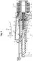
- FIG. 1shows, in a longitudinal section, a clutch actuator according to a first embodiment of the invention
- FIG. 2shows the detail II of FIG. 1 on an enlarged scale
- FIG. 3shows a flow diagram which illustrates the finding of the zero point position of the clutch by the clutch actuator
- FIG. 4shows, in a sectional view, a clutch actuator according to a second embodiment
- FIG. 5shows the region V of FIG. 4 on an enlarged scale.
- FIG. 1shows a clutch actuator 1 which serves to adjust a release lever 2 of a clutch (not shown here) in order to disengage and re-engage the clutch.
- the clutchcan be, in particular, a friction clutch in the power flow between a drive motor and a transmission of a heavy goods vehicle.
- a tappet 3Engaging on the release lever 2 is a tappet 3 , which is supported on a guide component 4 .
- a pushrod 5which is here embodied as a spindle, is supported on the opposite end of the guide component 4 . That end of the spindle 5 which faces away from the guide component is accommodated in a spindle nut 6 , which is mounted rotatably in a housing 8 of the clutch actuator 1 by means of rolling bearings 7 .
- the spindle nut 6is mounted for conjoint rotation on a rotor shaft 9 , which is part of a rotor 10 of an electric motor 11 .
- the spindle nut 6can be rotated in one or the other direction.
- a preload spring 12which is supported by one end on the housing and by the other end on the guide component 4 .
- the preload spring 12acts on the guide component 4 , the tappet 3 and hence the release lever 2 in the direction of disengagement of the clutch.
- the clutch actuator 1is shown in a state with a disengaged clutch.
- the spindle nut 6is rotated in the direction which results in a movement of the spindle 5 to the right. This movement is followed by the guide component 4 since it is pushed to the right by way of the tappet 3 ; the tappet 3 , in turn, is pushed to the right by the release lever 2 since said lever is pushed in the corresponding direction by the springs of the clutch and by the release lever.
- the release lever 2cannot move the tappet 3 further to the right.
- the guide component 4also comes to a halt since it is pushed to the left by the preload spring 12 . Accordingly, when the spindle nut 6 is operated further in the same direction of rotation, the front end of the spindle 5 rises from the contact surface in the guide component that lies opposite the spindle. The spindle 5 is thereby decoupled from vibration that would otherwise be transferred to the spindle in the coupled state of the clutch.
- the rotational position of the drive(here formed by the electric motor 11 with the rotor 10 , the rotor shaft 9 and the spindle nut 6 ) is detected.
- a rotation angle sensor 14which detects the rotation of the spindle nut 6 , is provided for this purpose.
- the spindle nut 6is provided with an annular permanent magnet 16 , which is mounted on the outer side of the spindle nut 6 for conjoint rotation therewith.
- the rotation angle sensor 14is mounted on a circuit board 18 , which extends within the housing 8 from the spindle 6 along the stroke of the guide component 4 .
- the sensor positionsare chosen in such a way that the entire stroke can be detected by them reliably and precisely.
- a permanent magnet 22Associated with the two stroke sensors 20 is a permanent magnet 22 , which is mounted in a fixed manner on the guide component 4 on the side thereof facing the stroke sensors 20 .
- the sensors 14 , 20can be Hall-effect sensors or GMR sensors. By means of these sensors, the rotation angle of the spindle nut 6 and the stroke of the guide component 4 can be detected precisely.
- the clutch actuator 1is controlled by a controller 24 , indicated schematically here, which comprises an input signal for the actuation of the clutch and an output for controlling the electric motor 11 of the drive.
- the controller 24furthermore receives the signals of the sensors 14 , 20 .
- the controller 24can perform further functions, but these are not relevant here and are therefore not explained specifically.
- the electric motor 11When the clutch is engaged, the electric motor 11 is operated in the direction of engagement of the clutch until the guide component 4 “comes to a halt” under the action of the preload spring 12 . In addition, the electric motor continues to be operated for a short time to ensure that the spindle 5 is released from the guide component 4 . Owing to the wear of the clutch, this point (also referred to as the “zero point” of the guide component 4 ) is not constant. For this reason, the current zero point of the clutch actuator is stored and regularly updated in the controller 24 .
- controller 24can determine the zero point.
- step 30the controller receives the command to start the electric motor 11 . This takes place in step 32 .
- the stroke sensors 20 and the rotation angle sensor 14are then interrogated (steps 34 and 36 ).
- step 38a check is made to determine whether a movement of the guide component 4 has been detected. If this is not the case, the motor position and the position of the guide component 4 continue to be monitored. If a movement of the guide component 4 is detected, the current position of the guide component 4 and the associated rotational position of the spindle nut 6 are stored as a starting point for the release travel, i.e. for the zero point, in step 40 . This concludes the process of storing the zero point as in step 42 .
- FIGS. 4 and 5A clutch actuator according to a second embodiment is shown in FIGS. 4 and 5 .
- the same reference signsare used for the components known from the first embodiment, and, to this extent, attention is drawn to the above explanations.
- the pushrod 5is embodied as a rack. This is driven by the electric motor 11 via a pinion 50 and a worm gear mechanism 52 . Accordingly, the rotation angle sensor 14 is here associated with the rotor shaft 9 .
- the pushrod 5is coupled directly to the tappet 3 .
- the tappet 3is snapped into the guide component 4 at its end interacting with the rack 5 .
- FIG. 5it can be seen that the front end of the rack 5 is raised slightly from the bottom of the recess in the tappet 3 in which the rack is received.
- the mode of operation of the clutch actuator according to the second embodimentcorresponds to the mode of operation of the clutch actuator according to the first embodiment, with the difference that, in the second embodiment, the rotational position of the rotor shaft 9 of the electric motor 11 is detected.
Landscapes
- Engineering & Computer Science (AREA)
- General Engineering & Computer Science (AREA)
- Mechanical Engineering (AREA)
- Physics & Mathematics (AREA)
- Electromagnetism (AREA)
- Fluid Mechanics (AREA)
- Connection Of Motors, Electrical Generators, Mechanical Devices, And The Like (AREA)
- Hydraulic Clutches, Magnetic Clutches, Fluid Clutches, And Fluid Joints (AREA)
Abstract
Description
Claims (9)
Applications Claiming Priority (2)
| Application Number | Priority Date | Filing Date | Title |
|---|---|---|---|
| DE102019134460.3ADE102019134460A1 (en) | 2019-12-16 | 2019-12-16 | Clutch actuator and method for controlling a clutch actuator |
| DE102019134460.3 | 2019-12-16 |
Publications (2)
| Publication Number | Publication Date |
|---|---|
| US20210180655A1 US20210180655A1 (en) | 2021-06-17 |
| US11434961B2true US11434961B2 (en) | 2022-09-06 |
Family
ID=73789855
Family Applications (1)
| Application Number | Title | Priority Date | Filing Date |
|---|---|---|---|
| US16/952,333ActiveUS11434961B2 (en) | 2019-12-16 | 2020-11-19 | Clutch actuator and method for controlling a clutch actuator |
Country Status (4)
| Country | Link |
|---|---|
| US (1) | US11434961B2 (en) |
| EP (1) | EP3839284B1 (en) |
| CN (1) | CN112984000B (en) |
| DE (1) | DE102019134460A1 (en) |
Families Citing this family (1)
| Publication number | Priority date | Publication date | Assignee | Title |
|---|---|---|---|---|
| DE102023124630A1 (en)* | 2023-09-12 | 2025-03-13 | Schaeffler Technologies AG & Co. KG | Bistable toggle actuator |
Citations (18)
| Publication number | Priority date | Publication date | Assignee | Title |
|---|---|---|---|---|
| US4546296A (en)* | 1983-05-12 | 1985-10-08 | Westinghouse Brake & Signal | Electric actuators |
| DE10157504A1 (en) | 2000-12-07 | 2002-08-08 | Luk Lamellen & Kupplungsbau | Actuator for automatically maneuvering of a clutch or gearbox of an automotive vehicle, has very compact design |
| US20030169033A1 (en)* | 2002-01-02 | 2003-09-11 | Gerald Tromblee | Non-contact position sensor |
| JP2005330942A (en)* | 2004-05-21 | 2005-12-02 | Toyota Motor Corp | Actuator position detection device and variable valve lift mechanism of internal combustion engine |
| DE60113946T2 (en) | 2000-11-21 | 2006-06-29 | Aisin Seiki K.K., Kariya | Control device for an actuator |
| US20120227524A1 (en)* | 2009-11-26 | 2012-09-13 | Ntn Corporation | Electric Actuator |
| US8324890B2 (en)* | 2009-09-18 | 2012-12-04 | Delphi Technologies, Inc. | Clutch position sensor for vehicle transmission |
| US20140004218A1 (en)* | 2011-03-15 | 2014-01-02 | Husky Injection Molding Systmes Ltd. | Mold-Tool System Including Actuation System |
| US20140048378A1 (en)* | 2012-08-20 | 2014-02-20 | Hyundai Motor Company | Clutch actuator unit |
| US20150070003A1 (en)* | 2013-09-10 | 2015-03-12 | KSR IP Holdings, LLC | Integrated brake control sensor |
| WO2015081951A1 (en) | 2013-12-06 | 2015-06-11 | Schaeffler Technologies AG & Co. KG | Actuator having a planetary roller spindle (pwg) |
| WO2018036582A1 (en)* | 2016-08-25 | 2018-03-01 | Schaeffler Technologies AG & Co. KG | Motor vehicle actuator having a high-resolution absolute sensor |
| KR20180068415A (en)* | 2016-12-14 | 2018-06-22 | 엘지이노텍 주식회사 | Power module and Dual clutch transmission |
| US20190040939A1 (en)* | 2016-02-09 | 2019-02-07 | Ntn Corporation | Ball screw device and electric actuator equpped with same |
| CN109565215A (en) | 2016-08-11 | 2019-04-02 | 舍弗勒技术股份两合公司 | Method for mutual calibration of a magnetic sensor device and an actuator, and actuator apparatus comprising an actuator and a magnetic sensor device |
| DE102018115682A1 (en)* | 2018-06-28 | 2020-01-02 | Hanning Elektro-Werke Gmbh & Co. Kg | Spindellinearverstellantrieb |
| US20200088247A1 (en)* | 2018-09-19 | 2020-03-19 | Fte Automotive Gmbh | Electric clutch actuator with a one-piece housing |
| US20200102990A1 (en)* | 2017-05-03 | 2020-04-02 | Schaeffler Technologies AG & Co. KG | Method for operating an actuator arrangement for a clutch operating system, and actuator arrangement |
Family Cites Families (14)
| Publication number | Priority date | Publication date | Assignee | Title |
|---|---|---|---|---|
| DE4320205A1 (en)* | 1993-06-18 | 1994-12-22 | Fichtel & Sachs Ag | Actuator for a motor vehicle friction clutch |
| DE19819780A1 (en)* | 1997-05-09 | 1998-11-12 | Luk Getriebe Systeme Gmbh | Automatic clutch for vehicle |
| NL1015234C2 (en)* | 2000-05-18 | 2001-11-20 | Skf Eng & Res Centre Bv | Actuator unit for a coupling. |
| ITTO20010986A1 (en)* | 2001-10-17 | 2003-04-17 | Sila Holding Ind S R L | AUTOMATIC STROKE ADJUSTMENT AND PLAY AND WEAR RECOVERY DEVICE FOR GROUPS OPERATED BY FL CABLE TRANSMISSION |
| DE102005027602A1 (en)* | 2004-06-30 | 2006-02-09 | Luk Lamellen Und Kupplungsbau Beteiligungs Kg | Method for balancing incremental path measuring device in actuator device of depressed clutch uses incremental sensor whose output signal at sudden change of force is fixed as reference signal |
| CN201078468Y (en)* | 2007-07-13 | 2008-06-25 | 北京创鑫恒源科技有限公司 | Electric screw mandrel type correcting unit for automatic clutch |
| EP2202423B1 (en)* | 2008-12-29 | 2011-07-06 | Magneti Marelli S.p.A. | Method of controlling an electro-actuated clutch for determining the closing position |
| JP2011106614A (en)* | 2009-11-19 | 2011-06-02 | Aisin Seiki Co Ltd | Clutch actuator |
| CN101852255B (en)* | 2010-05-21 | 2012-07-18 | 北京工业大学 | Electric operator for general-purpose mechanical automatic transmission clutch |
| CN102062165B (en)* | 2010-12-23 | 2012-06-27 | 重庆青山工业有限责任公司 | Mechanical guyed automatic transmission clutch execution mechanism |
| JP5977016B2 (en)* | 2011-10-26 | 2016-08-24 | Ntn株式会社 | Electric linear actuator and electric brake device |
| DE102016201069A1 (en)* | 2015-01-30 | 2016-08-04 | Schaeffler Technologies AG & Co. KG | Drive unit with an electronically commutated electric motor and method for determining a rotor position of an electronically commutated electric motor |
| DE102015216509A1 (en)* | 2015-08-28 | 2017-03-02 | Schaeffler Technologies AG & Co. KG | Angle measuring device for a rotary driven linear actuator |
| WO2017091433A1 (en)* | 2015-11-25 | 2017-06-01 | Means Industries, Inc. | Electromechanical apparatus for use with a controllable coupling assembly and coupling and electromechanical control assembly |
- 2019
- 2019-12-16DEDE102019134460.3Apatent/DE102019134460A1/ennot_activeWithdrawn
- 2020
- 2020-11-19USUS16/952,333patent/US11434961B2/enactiveActive
- 2020-12-09CNCN202011448395.3Apatent/CN112984000B/enactiveActive
- 2020-12-09EPEP20212638.9Apatent/EP3839284B1/enactiveActive
Patent Citations (21)
| Publication number | Priority date | Publication date | Assignee | Title |
|---|---|---|---|---|
| US4546296A (en)* | 1983-05-12 | 1985-10-08 | Westinghouse Brake & Signal | Electric actuators |
| DE60113946T2 (en) | 2000-11-21 | 2006-06-29 | Aisin Seiki K.K., Kariya | Control device for an actuator |
| DE10157504A1 (en) | 2000-12-07 | 2002-08-08 | Luk Lamellen & Kupplungsbau | Actuator for automatically maneuvering of a clutch or gearbox of an automotive vehicle, has very compact design |
| US20030169033A1 (en)* | 2002-01-02 | 2003-09-11 | Gerald Tromblee | Non-contact position sensor |
| JP2005330942A (en)* | 2004-05-21 | 2005-12-02 | Toyota Motor Corp | Actuator position detection device and variable valve lift mechanism of internal combustion engine |
| US8324890B2 (en)* | 2009-09-18 | 2012-12-04 | Delphi Technologies, Inc. | Clutch position sensor for vehicle transmission |
| US20120227524A1 (en)* | 2009-11-26 | 2012-09-13 | Ntn Corporation | Electric Actuator |
| US20140004218A1 (en)* | 2011-03-15 | 2014-01-02 | Husky Injection Molding Systmes Ltd. | Mold-Tool System Including Actuation System |
| US20140048378A1 (en)* | 2012-08-20 | 2014-02-20 | Hyundai Motor Company | Clutch actuator unit |
| US20150070003A1 (en)* | 2013-09-10 | 2015-03-12 | KSR IP Holdings, LLC | Integrated brake control sensor |
| WO2015081951A1 (en) | 2013-12-06 | 2015-06-11 | Schaeffler Technologies AG & Co. KG | Actuator having a planetary roller spindle (pwg) |
| US20160305519A1 (en) | 2013-12-06 | 2016-10-20 | Schaeffler Technologies AG & Co. KG | Actuator with planetary screw drive (psd) |
| US20190040939A1 (en)* | 2016-02-09 | 2019-02-07 | Ntn Corporation | Ball screw device and electric actuator equpped with same |
| CN109565215A (en) | 2016-08-11 | 2019-04-02 | 舍弗勒技术股份两合公司 | Method for mutual calibration of a magnetic sensor device and an actuator, and actuator apparatus comprising an actuator and a magnetic sensor device |
| WO2018036582A1 (en)* | 2016-08-25 | 2018-03-01 | Schaeffler Technologies AG & Co. KG | Motor vehicle actuator having a high-resolution absolute sensor |
| DE102016215945A1 (en) | 2016-08-25 | 2018-03-01 | Schaeffler Technologies AG & Co. KG | Motor vehicle actuator with high-resolution absolute sensor |
| KR20180068415A (en)* | 2016-12-14 | 2018-06-22 | 엘지이노텍 주식회사 | Power module and Dual clutch transmission |
| US20200102990A1 (en)* | 2017-05-03 | 2020-04-02 | Schaeffler Technologies AG & Co. KG | Method for operating an actuator arrangement for a clutch operating system, and actuator arrangement |
| DE102018115682A1 (en)* | 2018-06-28 | 2020-01-02 | Hanning Elektro-Werke Gmbh & Co. Kg | Spindellinearverstellantrieb |
| US20200088247A1 (en)* | 2018-09-19 | 2020-03-19 | Fte Automotive Gmbh | Electric clutch actuator with a one-piece housing |
| DE102018123039A1 (en) | 2018-09-19 | 2020-03-19 | Fte Automotive Gmbh | Electrical clutch actuator with a one-piece housing |
Non-Patent Citations (2)
| Title |
|---|
| Extended European Search Report dated May 25, 2021 in European Patent Application No. 20212638.9, citing documents AO and AP therein, 6 pages. |
| German Search Report dated Jul. 31, 2020 in German Application 10 2019 134 460.3 filed Dec. 16, 2019 (with English Translation of Categories of Cited Documents and Written Opinion), citing documents AO-AR therein, 4 pages. |
Also Published As
| Publication number | Publication date |
|---|---|
| EP3839284B1 (en) | 2023-04-19 |
| US20210180655A1 (en) | 2021-06-17 |
| CN112984000A (en) | 2021-06-18 |
| EP3839284A1 (en) | 2021-06-23 |
| CN112984000B (en) | 2024-01-02 |
| DE102019134460A1 (en) | 2021-06-17 |
Similar Documents
| Publication | Publication Date | Title |
|---|---|---|
| US9121457B2 (en) | Wear compensator of clutch actuator | |
| US10690243B2 (en) | Range switching device for automatic transmission and switching method therefor | |
| US8443954B2 (en) | Clutch | |
| US9234550B2 (en) | Actuator for clutch | |
| JP6192842B2 (en) | Actuator which operates hydraulic clutch adjuster, which is locked at the maximum position, and electrically operated clutch system | |
| US11434961B2 (en) | Clutch actuator and method for controlling a clutch actuator | |
| WO2014196420A1 (en) | Electromagnetic actuator | |
| KR20170118082A (en) | Actuator with planetary rolling screw spindle drive | |
| EP3457091B1 (en) | Actuator position sensor mechanism | |
| CN110925322B (en) | Electric clutch actuator with gear mechanism support plate | |
| US10844912B2 (en) | Reduced vibration clutch actuator | |
| CN113015862A (en) | Electric brake and control device | |
| US7350634B2 (en) | Method for adjusting an incremental path measurement unit in an actuation device of a pressure-closed clutch as well as an actuation device | |
| SE541641C2 (en) | Failsafe electrical clutch actuator | |
| CN114396435B (en) | Electrically driven clutch actuator | |
| EP0026656A2 (en) | Vehicle speed control apparatus | |
| KR101526387B1 (en) | Clutch actuator correction system and method thereof | |
| US8585545B2 (en) | Method of controlling an electro-actuated clutch for determining the closing position | |
| WO2011027693A1 (en) | Clutch operation device | |
| KR102654459B1 (en) | Clutch actuator control device with wear compensation device and control method thereof | |
| EP2192319A1 (en) | Clutch system | |
| GB2527906A (en) | Torque sensor | |
| EP3626989B1 (en) | Electric clutch actuator with spring-loaded thrust piece | |
| CN111207162A (en) | Method for adjusting the preload of a clutch actuating system with an automatic release system | |
| CN107435693A (en) | For the device for the clutch for manipulating vehicle |
Legal Events
| Date | Code | Title | Description |
|---|---|---|---|
| AS | Assignment | Owner name:FTE AUTOMOTIVE GMBH, GERMANY Free format text:ASSIGNMENT OF ASSIGNORS INTEREST;ASSIGNORS:OSTROHOV, DIMITRI;STAWINOGA, PAUL;SIGNING DATES FROM 20201112 TO 20201115;REEL/FRAME:054416/0571 | |
| FEPP | Fee payment procedure | Free format text:ENTITY STATUS SET TO UNDISCOUNTED (ORIGINAL EVENT CODE: BIG.); ENTITY STATUS OF PATENT OWNER: LARGE ENTITY | |
| STPP | Information on status: patent application and granting procedure in general | Free format text:APPLICATION DISPATCHED FROM PREEXAM, NOT YET DOCKETED | |
| STPP | Information on status: patent application and granting procedure in general | Free format text:DOCKETED NEW CASE - READY FOR EXAMINATION | |
| STPP | Information on status: patent application and granting procedure in general | Free format text:NON FINAL ACTION MAILED | |
| STPP | Information on status: patent application and granting procedure in general | Free format text:RESPONSE TO NON-FINAL OFFICE ACTION ENTERED AND FORWARDED TO EXAMINER | |
| STPP | Information on status: patent application and granting procedure in general | Free format text:FINAL REJECTION MAILED | |
| STPP | Information on status: patent application and granting procedure in general | Free format text:RESPONSE AFTER FINAL ACTION FORWARDED TO EXAMINER | |
| STPP | Information on status: patent application and granting procedure in general | Free format text:NOTICE OF ALLOWANCE MAILED -- APPLICATION RECEIVED IN OFFICE OF PUBLICATIONS | |
| STPP | Information on status: patent application and granting procedure in general | Free format text:PUBLICATIONS -- ISSUE FEE PAYMENT VERIFIED | |
| STCF | Information on status: patent grant | Free format text:PATENTED CASE | |
| AS | Assignment | Owner name:VALEO POWERTRAIN GMBH, GERMANY Free format text:MERGER AND CHANGE OF NAME;ASSIGNORS:FTE AUTOMOTIVE GMBH;FTE ASIA GMBH;REEL/FRAME:069875/0816 Effective date:20230101 |