US11433190B2 - Method and system for controlling pressurization of a patient cavity using a pressure sensor of a medical appliance - Google Patents
Method and system for controlling pressurization of a patient cavity using a pressure sensor of a medical applianceDownload PDFInfo
- Publication number
- US11433190B2 US11433190B2US16/206,284US201816206284AUS11433190B2US 11433190 B2US11433190 B2US 11433190B2US 201816206284 AUS201816206284 AUS 201816206284AUS 11433190 B2US11433190 B2US 11433190B2
- Authority
- US
- United States
- Prior art keywords
- pressure sensor
- received
- signals indicative
- insufflator
- medical appliance
- Prior art date
- Legal status (The legal status is an assumption and is not a legal conclusion. Google has not performed a legal analysis and makes no representation as to the accuracy of the status listed.)
- Active, expires
Links
- 238000000034methodMethods0.000titleclaimsabstractdescription33
- 239000012530fluidSubstances0.000claimsabstractdescription24
- 230000004044responseEffects0.000claimsabstractdescription6
- 238000009530blood pressure measurementMethods0.000claimsdescription31
- 230000001276controlling effectEffects0.000description7
- 210000000683abdominal cavityAnatomy0.000description5
- 238000010586diagramMethods0.000description5
- 238000005259measurementMethods0.000description5
- CURLTUGMZLYLDI-UHFFFAOYSA-NCarbon dioxideChemical compoundO=C=OCURLTUGMZLYLDI-UHFFFAOYSA-N0.000description4
- 238000012545processingMethods0.000description4
- 238000001356surgical procedureMethods0.000description4
- 230000008859changeEffects0.000description3
- 238000003780insertionMethods0.000description3
- 230000037431insertionEffects0.000description3
- 230000001012protectorEffects0.000description3
- 229910002092carbon dioxideInorganic materials0.000description2
- 239000001569carbon dioxideSubstances0.000description2
- 230000000694effectsEffects0.000description2
- 239000000779smokeSubstances0.000description2
- 238000010561standard procedureMethods0.000description2
- 210000000115thoracic cavityAnatomy0.000description2
- 206010016717FistulaDiseases0.000description1
- 210000001015abdomenAnatomy0.000description1
- 230000003187abdominal effectEffects0.000description1
- 210000004100adrenal glandAnatomy0.000description1
- 230000004075alterationEffects0.000description1
- 239000008280bloodSubstances0.000description1
- 210000004369bloodAnatomy0.000description1
- 210000000038chestAnatomy0.000description1
- 238000011109contaminationMethods0.000description1
- 230000009849deactivationEffects0.000description1
- 238000012976endoscopic surgical procedureMethods0.000description1
- 230000003890fistulaEffects0.000description1
- 210000000232gallbladderAnatomy0.000description1
- 238000002357laparoscopic surgeryMethods0.000description1
- 238000012423maintenanceMethods0.000description1
- 239000000463materialSubstances0.000description1
- 238000012544monitoring processMethods0.000description1
- 210000001672ovaryAnatomy0.000description1
- 210000003200peritoneal cavityAnatomy0.000description1
- 230000001105regulatory effectEffects0.000description1
- 239000000523sampleSubstances0.000description1
- 210000000952spleenAnatomy0.000description1
- 238000006467substitution reactionMethods0.000description1
- 210000004291uterusAnatomy0.000description1
- 230000000007visual effectEffects0.000description1
Images


Classifications
- A—HUMAN NECESSITIES
- A61—MEDICAL OR VETERINARY SCIENCE; HYGIENE
- A61M—DEVICES FOR INTRODUCING MEDIA INTO, OR ONTO, THE BODY; DEVICES FOR TRANSDUCING BODY MEDIA OR FOR TAKING MEDIA FROM THE BODY; DEVICES FOR PRODUCING OR ENDING SLEEP OR STUPOR
- A61M13/00—Insufflators for therapeutic or disinfectant purposes, i.e. devices for blowing a gas, powder or vapour into the body
- A61M13/003—Blowing gases other than for carrying powders, e.g. for inflating, dilating or rinsing
- A—HUMAN NECESSITIES
- A61—MEDICAL OR VETERINARY SCIENCE; HYGIENE
- A61B—DIAGNOSIS; SURGERY; IDENTIFICATION
- A61B17/00—Surgical instruments, devices or methods
- A61B17/34—Trocars; Puncturing needles
- A61B17/3474—Insufflating needles, e.g. Veress needles
- A—HUMAN NECESSITIES
- A61—MEDICAL OR VETERINARY SCIENCE; HYGIENE
- A61M—DEVICES FOR INTRODUCING MEDIA INTO, OR ONTO, THE BODY; DEVICES FOR TRANSDUCING BODY MEDIA OR FOR TAKING MEDIA FROM THE BODY; DEVICES FOR PRODUCING OR ENDING SLEEP OR STUPOR
- A61M39/00—Tubes, tube connectors, tube couplings, valves, access sites or the like, specially adapted for medical use
- A61M39/02—Access sites
- A61M39/0247—Semi-permanent or permanent transcutaneous or percutaneous access sites to the inside of the body
- A—HUMAN NECESSITIES
- A61—MEDICAL OR VETERINARY SCIENCE; HYGIENE
- A61B—DIAGNOSIS; SURGERY; IDENTIFICATION
- A61B90/00—Instruments, implements or accessories specially adapted for surgery or diagnosis and not covered by any of the groups A61B1/00 - A61B50/00, e.g. for luxation treatment or for protecting wound edges
- A61B90/06—Measuring instruments not otherwise provided for
- A61B2090/064—Measuring instruments not otherwise provided for for measuring force, pressure or mechanical tension
- A—HUMAN NECESSITIES
- A61—MEDICAL OR VETERINARY SCIENCE; HYGIENE
- A61M—DEVICES FOR INTRODUCING MEDIA INTO, OR ONTO, THE BODY; DEVICES FOR TRANSDUCING BODY MEDIA OR FOR TAKING MEDIA FROM THE BODY; DEVICES FOR PRODUCING OR ENDING SLEEP OR STUPOR
- A61M16/00—Devices for influencing the respiratory system of patients by gas treatment, e.g. ventilators; Tracheal tubes
- A61M16/0003—Accessories therefor, e.g. sensors, vibrators, negative pressure
- A61M2016/0027—Accessories therefor, e.g. sensors, vibrators, negative pressure pressure meter
- A—HUMAN NECESSITIES
- A61—MEDICAL OR VETERINARY SCIENCE; HYGIENE
- A61M—DEVICES FOR INTRODUCING MEDIA INTO, OR ONTO, THE BODY; DEVICES FOR TRANSDUCING BODY MEDIA OR FOR TAKING MEDIA FROM THE BODY; DEVICES FOR PRODUCING OR ENDING SLEEP OR STUPOR
- A61M39/00—Tubes, tube connectors, tube couplings, valves, access sites or the like, specially adapted for medical use
- A61M39/02—Access sites
- A61M39/0247—Semi-permanent or permanent transcutaneous or percutaneous access sites to the inside of the body
- A61M2039/0264—Semi-permanent or permanent transcutaneous or percutaneous access sites to the inside of the body with multiple inlets or multiple outlets
- A—HUMAN NECESSITIES
- A61—MEDICAL OR VETERINARY SCIENCE; HYGIENE
- A61M—DEVICES FOR INTRODUCING MEDIA INTO, OR ONTO, THE BODY; DEVICES FOR TRANSDUCING BODY MEDIA OR FOR TAKING MEDIA FROM THE BODY; DEVICES FOR PRODUCING OR ENDING SLEEP OR STUPOR
- A61M39/00—Tubes, tube connectors, tube couplings, valves, access sites or the like, specially adapted for medical use
- A61M39/02—Access sites
- A61M39/0247—Semi-permanent or permanent transcutaneous or percutaneous access sites to the inside of the body
- A61M2039/0279—Semi-permanent or permanent transcutaneous or percutaneous access sites to the inside of the body for introducing medical instruments into the body, e.g. endoscope, surgical tools
- A—HUMAN NECESSITIES
- A61—MEDICAL OR VETERINARY SCIENCE; HYGIENE
- A61M—DEVICES FOR INTRODUCING MEDIA INTO, OR ONTO, THE BODY; DEVICES FOR TRANSDUCING BODY MEDIA OR FOR TAKING MEDIA FROM THE BODY; DEVICES FOR PRODUCING OR ENDING SLEEP OR STUPOR
- A61M2205/00—General characteristics of the apparatus
- A61M2205/16—General characteristics of the apparatus with back-up system in case of failure
- A—HUMAN NECESSITIES
- A61—MEDICAL OR VETERINARY SCIENCE; HYGIENE
- A61M—DEVICES FOR INTRODUCING MEDIA INTO, OR ONTO, THE BODY; DEVICES FOR TRANSDUCING BODY MEDIA OR FOR TAKING MEDIA FROM THE BODY; DEVICES FOR PRODUCING OR ENDING SLEEP OR STUPOR
- A61M2205/00—General characteristics of the apparatus
- A61M2205/33—Controlling, regulating or measuring
- A61M2205/3331—Pressure; Flow
- A61M2205/3344—Measuring or controlling pressure at the body treatment site
- A—HUMAN NECESSITIES
- A61—MEDICAL OR VETERINARY SCIENCE; HYGIENE
- A61M—DEVICES FOR INTRODUCING MEDIA INTO, OR ONTO, THE BODY; DEVICES FOR TRANSDUCING BODY MEDIA OR FOR TAKING MEDIA FROM THE BODY; DEVICES FOR PRODUCING OR ENDING SLEEP OR STUPOR
- A61M2205/00—General characteristics of the apparatus
- A61M2205/33—Controlling, regulating or measuring
- A61M2205/3331—Pressure; Flow
- A61M2205/3358—Measuring barometric pressure, e.g. for compensation
- A—HUMAN NECESSITIES
- A61—MEDICAL OR VETERINARY SCIENCE; HYGIENE
- A61M—DEVICES FOR INTRODUCING MEDIA INTO, OR ONTO, THE BODY; DEVICES FOR TRANSDUCING BODY MEDIA OR FOR TAKING MEDIA FROM THE BODY; DEVICES FOR PRODUCING OR ENDING SLEEP OR STUPOR
- A61M2205/00—General characteristics of the apparatus
- A61M2205/35—Communication
- A61M2205/3546—Range
- A61M2205/3569—Range sublocal, e.g. between console and disposable
- A—HUMAN NECESSITIES
- A61—MEDICAL OR VETERINARY SCIENCE; HYGIENE
- A61M—DEVICES FOR INTRODUCING MEDIA INTO, OR ONTO, THE BODY; DEVICES FOR TRANSDUCING BODY MEDIA OR FOR TAKING MEDIA FROM THE BODY; DEVICES FOR PRODUCING OR ENDING SLEEP OR STUPOR
- A61M2205/00—General characteristics of the apparatus
- A61M2205/35—Communication
- A61M2205/3576—Communication with non implanted data transmission devices, e.g. using external transmitter or receiver
- A61M2205/3592—Communication with non implanted data transmission devices, e.g. using external transmitter or receiver using telemetric means, e.g. radio or optical transmission
- A—HUMAN NECESSITIES
- A61—MEDICAL OR VETERINARY SCIENCE; HYGIENE
- A61M—DEVICES FOR INTRODUCING MEDIA INTO, OR ONTO, THE BODY; DEVICES FOR TRANSDUCING BODY MEDIA OR FOR TAKING MEDIA FROM THE BODY; DEVICES FOR PRODUCING OR ENDING SLEEP OR STUPOR
- A61M2205/00—General characteristics of the apparatus
- A61M2205/50—General characteristics of the apparatus with microprocessors or computers
- A61M2205/502—User interfaces, e.g. screens or keyboards
Definitions
- the present invention disclosurerelates generally to medical procedures and more particularly to a method and system for controlling pressurization of a patient cavity using a pressure sensor of a medical appliance.
- Laparoscopic surgeryis a standard procedure in hospitals. Abdominal and chest cavity operations are being performed with instruments inserted through small incisions into interior portions of the body. Such laparoscopic procedures are now considered the treatment of choice for operations such as the removal of the gall bladder, spleen, adrenal glands, uterus, and ovaries. These laparoscopic procedures are accomplished via access through a device typically known as a trocar.
- a trocarfacilitates the introduction of laparoscopic instruments into the abdomen or chest of the body. These instruments are typically introduced into regions under fluid pressure. This fluid may be a gas, referred to herein as an insufflation gas.
- insufflationProviding an insufflation gas into a body cavity is referred to as insufflation.
- insufflationis performed by providing a regulated pressurized insufflation gas to the peritoneal cavity via a cannula of the trocar.
- This insufflation gastypically carbon dioxide, is supplied to a connection on the trocar tube by a flexible hose attached thereto.
- the medical instrument going through the innermost tube of the trocarshould be sealed relative to the trocar so the insufflation gas will not escape from the patient.
- a physiciancan use a trocar device to introduce different types of instruments into a patient.
- the insufflation gasis delivered into a body cavity during specific medical procedures or treatment is done via a trocar that also allows insertion of an instrument via the innermost tube of the trocar.
- the purpose of using such a deviceis to inflate or distend the body cavity to (1) allow the surgeon to explore the area in which the surgery will be performed and (2) provide a view of the site to be treated or observed.
- Insufflationis used in many common procedures including endoscopic surgical procedures, laparoscopic procedures performed on the abdominal cavity and orthoscopic procedures performed on the chest cavity.
- Additional medical access devicese.g., trocars
- trocarscan be used during the same surgical procedure to remove surgical smoke from the patient cavity or to continuously measure pressure within the body cavity.
- a methodincludes positioning a medical appliance having a primary pressure sensor at or within a patient incision site and supplying an insufflation fluid to the patient cavity.
- the methodfurther includes measuring a pressure in the patient cavity by the primary pressure sensor and controlling the supply of insufflation fluid by an insufflator to the patient cavity based at least on the measured pressure.
- the methodfurther includes determining, by a processor associated with the insufflator, that the measured pressure may be inaccurate and, in response to determining that the measured pressure may be inaccurate, controlling, by the insufflator, the supply of the insufflation fluid to the patient cavity based at least on a pressure measured by a backup pressure sensor.
- a methodallows for continuous monitoring of pressure associated with a patient cavity even in the event of a pressure sensor failure. This allows safe completion of a surgical procedure without subjecting the patient to potential harm associated with deactivation of an associated insufflator. Further, providing a pressure sensor in conjunction with a medical access device nearer the patient cavity provides better pressure sensing and more stable control and does not require stopping the associated surgical procedure to measure pressure according to certain standard techniques.
- FIG. 1is a schematic diagram showing the distal end of a trocar having an associated pressure sensor, the distal end placed in the abdominal cavity of a patient;
- FIGS. 2A and 2Bare block diagrams illustrating additional details of components of the system of FIG. 1 that may be used to effect pressure determination and resulting actions;
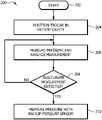
- FIG. 3is a flow chart illustrating a method that includes switching control of an insufflator to be based on pressure measurements of a backup pressure sensor
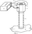
- FIG. 4is a schematic diagram showing a multiple access port having an associated pressure sensor, wherein the multiple access port provides access to the abdominal cavity of a patient.
- the present disclosurerelates to a method for controlling pressurization of a patient cavity.
- the teachings of the disclosurerecognize that more accurate control of such pressurization can occur by measuring the pressure in a patient cavity directly through use of a pressure sensor located on or associated with a trocar such that the pressure sensor is in direct contact with the gas region in the patient cavity but that in some instances such pressure sensors can be damaged and provide erroneous data.
- itcan be desirable to monitor such pressure measurements, and when the data appear faulty, switch control of such pressurization to be based on a secondary or back up measure of pressure within the pressure cavity.
- a backup pressure sensor located in or on the insufflatoris used to provide such a backup pressure measurement, and in some embodiments a backup pressure sensor is located in, on, or through the trocar.
- Example embodimentsare best understood by referring to FIGS. 1 through 3B of the drawings and the description below, like numerals being used for like and corresponding parts of the various drawings.
- FIG. 1is a schematic diagram showing the distal end 24 of a trocar 14 placed in the abdominal cavity 20 of a patient.
- an insufflator 10supplies insufflation gas through conduit 12 and trocar 14 to patient cavity 20 .
- Trocar 14allows insertion of a surgical instrument 28 into patient cavity 20 .
- Trocar 14has a primary pressure sensor 22 on or associated with the trocar 14 .
- the locationcan be anywhere in, on, or through trocar 14 or associated with trocar 14 ; however, as described in greater detail below, in one embodiment primary pressure sensor 22 is located on the exterior of trocar 14 such that changes of pressure within trocar 14 due to supply of insufflation gas to patient cavity 20 do not affect the pressure measured by primary pressure sensor 22 .
- primary pressure sensor 22is an absolute pressure sensor that can measure pressure in patient cavity 20 (if disposed within patient cavity 20 ) or in the room in which the associated operation is taking place.
- Primary pressure sensor 22is coupled to insufflator through any suitable technique, including a wired connection 25 or a wireless connection.
- Primary pressure sensor 22supplies pressure data to insufflator 10 .
- Insufflator 10uses this pressure data to control the supply on insufflation gas by insufflator 10 .
- thismay include determining the change in height of trocar 14 relative to changes in cavity pressure and thus the resulting change in height of patient cavity 20 , as described in greater detail in co-pending application Ser. No. 15/293,013 entitled Method and System for Controlling Pressurization of a Patient Cavity Using Cavity Distension Measured by a Pressure Sensor of a Trocar incorporated herein by reference. Additional details of certain portions of FIG. 1 are described below.
- Insufflator 10may be any suitable source of insufflation gas at any suitable pressure and may include a pressurized gas source. Insufflator may adjust the supply of insufflation gas to patient cavity 20 by adjusting the pressure and/or the volume of insufflation gas supplied to patient cavity 20 . Insufflator may include appropriate hardware and/or software for processing signals indicative of pressures measured by primary pressure sensor 22 and processing such signals to convert them into useful information, such as converting them into pressures, heights, and/or other data that can be used control the flow of insufflation gas to patient cavity 20 , and further for processing such data to determine a desired pressure and/or volume of insufflation gas supplied to patient cavity 20 and for effecting such delivery.
- Conduit 12may be any suitable conduit for providing an insufflation gas to a portion of a trocar.
- An example of conduit 12includes flexible PVC tubing.
- the insufflation gasmay be any suitable gas used for insufflation purposes. In one example, insufflation case is carbon dioxide.
- Trocar 14may be any suitable trocar through which insufflation gas may be supplied to a patient cavity. Examples of one or more trocars are provided in U.S. Pat. No. 8,715,219 (the '219 patent), U.S. Pat. No. 7,285,112 (the '112 patent), and U.S. Pat. No. 8,216,189 (the '189 patent), which are hereby incorporated by reference as if fully set forth herein. Trocar 14 may be have a single lumen or may be formed with an inner tubular lumen and an outer tubular lumen such that insufflation gas may be supplied through one of the lumens but not the other.
- any of the lumensmay be divided into multiple, separate chambers, such that gas in one chamber does not enter the other chamber.
- Examples of the above multiple lumens and multiple chambered trocarsare described in U.S. application Ser. No. 14/792,873, entitled “Method and System for Gas Maintenance to a Body Cavity Using a Trocar,” which is hereby incorporated by reference.
- Trocar 14may be open or closed at the distal end 24 , as the application of the trocar would allow.
- Primary pressure sensor 22may be any sensor capable of sensing pressure or a change in pressure. Primary pressure sensor 22 may measure absolute pressure or a pressure relative to some other pressure. In some embodiments, primary pressure sensor 22 is an absolute sensor that can measure pressure in patient cavity 20 (if disposed within patient cavity 20 ) or in the room in which the associated operation is taking place. In particular embodiments, primary pressure sensor 22 can measure absolute barometric pressures with an accuracy of less than 1 Pascal pressure and therefore have the ability to measure the relative changes in altitude of close to one inch. Such pressure sensors are readily available in the marketplace.
- FIGS. 2A and 2Bare block diagrams illustrating additional details of components of the system of FIGURE that may be used to effect pressure measurement and resulting insufflator control.
- FIG. 2Aillustrates additional details of insufflator 10 , according to one embodiment.
- insufflator 10includes a memory 40 and a processor 42 communicatively coupled to the memory 40 .
- Memory 40stores a pressure application 44 , which may include logic for effecting pressure and altitude determination as described with respect to the other FIGURES as well as control of the supply of insufflation gas to patient cavity 20 .
- a backup pressure sensor 26is provided.
- insufflator 10includes a backup pressure sensor 26 .
- Backup pressure sensor 26may be used to measure pressure associated with trocar 14 in the event or problems associated with primary pressure sensor 22 , as described in greater detail below in conjunction with FIG. 3 .
- backup pressure sensor 26is provided on trocar 14 , as illustrated in FIG. 1 .
- the teachings of the disclosurerecognize that primary pressure sensor 22 may experience problems due to being located a larger distance from an associated processor, which leads to potential for erroneous readings and interference.
- Primary pressure sensor 22may be any suitable pressure sensor, including the pressure sensors described above as being suitable as primary pressure sensor 22 .
- FIG. 2Billustrates an alternative embodiment of the system of FIG. 1 in which an insufflator 110 includes only standard features and is communicatively coupled through a connection 114 to a pressure module 112 .
- Pressure module 112includes components analogous to those described with respect to FIG. 2A , including a backup pressure sensor 126 , but are included in this stand-alone pressure module.
- Connection 114 between insufflator 110 and pressure module 112may be wired or wireless. It will be understood that although a software-based system is illustrated in FIGS. 2A and 2B the logic described herein could instead be implemented through hardware circuits or a combination of hardware and software.
- FIG. 3is a flow chart illustrating a method 200 that includes use of a primary pressure sensor and a backup pressure sensor associated with a trocar.
- the methodmay utilize structural items such as those described in FIGS. 1A through 2B or may use alternative structural items.
- Computational steps described belowmay be performed by any suitable computation device, including insufflator 10 and pressure module 112 , for example.
- the methodbegins at step 202 .
- a trocar having a primary pressure sensoris positioned in a patient cavity.
- the pressure sensorin located on, or associated with, the trocar such that the primary pressure sensor can provide a direct measurement of a pressure in a patient cavity when a portion of the trocar is positioned in the patient cavity.
- the primary pressure sensorrepeatedly measures a pressure within the patient cavity and communicates a signal indicative of the measurement to a processor associated with an insufflator. Also at step 206 , the processor analyzes the measured pressure for indications of whether the signals indicative of the measured pressure being inaccurate or otherwise suggesting that the primary pressure sensor is operating in a less than optimal manner.
- any suitable factorsmay be considered in such analysis; however, certain factors that may indicate the primary pressure sensor is operating than a less than optimal manner include (1) whether the received signal is not within an expected range for the received signal; (2) whether error data is received, such as whether errors have occurred due to interference from a power signal, the wrong number of bits have been received, data is received in the wrong format, or data is received with improper spacing (3) whether proper acknowledgment bits are not received from the primary pressure sensor, (4) whether the received signal is not within an expected voltage range, (5) whether expected new updated status bits are not received, such as whether a signal has changed enough to indicate a new measurement has occurred as opposed to a signal being so close to a previous signal to indicate no new measurement has occurred; and (6) in the case of two or more pressure sensors located on or near trocar 14 , whether measurements by the two or more sensors are not within a certain range of each other.
- a processordetermines, whether the above analysis suggests the primary pressure sensor is not measuring accurately or otherwise not operating in a less than optimal fashion. If not, then processing returns to step 206 , and if so, the control by the insufflator is switched to be based on pressure sensed by a backup sensor at step 210 .
- a backup pressure sensor 210is usually not as accurate a measure of the pressure within the patient cavity and as such not as desirable for use in controlling an insufflator associated with a trocar, when problems arise with a primary pressure sensor positioned on or associated with a trocar such the direct pressure measurements within a patient cavity can be made, it can be advantageous to at least temporarily switch control to be based on pressure measurements made by a backup pressure sensor located at the insufflator.
- the methodconcludes at step 212 .
- primary pressure sensor 22may be located on, in, or through other medical appliances as well.
- medical appliancesmay be or include one of: a needle (e.g., veress needle, fistula, Huber, spinal), a stapler, a grasper, a pair of scissors, a scalpel, a cutter, an electrode, an end seal, a probe, a multiple access port, and a single access port.
- primary pressure sensor 22may be located on, in, or through any suitable medical appliance.
- this disclosurerecognizes any medical appliance that can puncture the skin as a medical appliance.
- FIG. 4illustrates primary pressure sensor 22 being part of or added to a medical port.
- a medical portmay be single access or multiple access.
- a single access portincludes one access point by which to introduce fluids and/or medical instruments into a patient and a multiple access port includes more than one access point by which to introduce fluids and/or medical instruments into a patient.
- FIG. 4illustrates a particular type of multiple access port known as a GelPort.
- a GelPort Laparascopic Systemgenerally includes a GelSeal® cap and a wound protector/retractor.
- the wound protector/retractoris configured to extend through an incision site to patient cavity 20 and the GelSeal® cap provides a seal for the wound protector/retractor.
- GelSeal® capmay comprise a penetrable material that permits the insertion of one or more other medical appliances (e.g., trocar 22 , a scalpel, etc.).
- insufflation gasmay be introduced into patient cavity 20 and smoke may be removed from patient cavity 20 through GelSeal® cap.
- primary pressure sensor 22may be included or added onto GelSeal® cap 402 in a manner that permits pressure readings to be taken with respect to patient cavity 20 .
- primary pressure sensor 22 or backup sensor 26may be coupled to a device (e.g., an insufflator 10 , a visual display) via wired connection 25 .
- wired connection 25includes sheathing 404 to shield wired connection 25 from electromagnetic frequencies. All of a part of wired connection 25 may be shielded. As illustrated in FIG. 4 , wired connection 25 is shielded by sheath 404 and is coupled to backup sensor 26 which provides a backup pressure measurement for primary pressure sensor 22 .
Landscapes
- Health & Medical Sciences (AREA)
- Life Sciences & Earth Sciences (AREA)
- Heart & Thoracic Surgery (AREA)
- Animal Behavior & Ethology (AREA)
- Public Health (AREA)
- Engineering & Computer Science (AREA)
- Biomedical Technology (AREA)
- Veterinary Medicine (AREA)
- General Health & Medical Sciences (AREA)
- Hematology (AREA)
- Surgery (AREA)
- Anesthesiology (AREA)
- Medical Informatics (AREA)
- Pathology (AREA)
- Molecular Biology (AREA)
- Nuclear Medicine, Radiotherapy & Molecular Imaging (AREA)
- Biophysics (AREA)
- Gastroenterology & Hepatology (AREA)
- Pulmonology (AREA)
- Endoscopes (AREA)
- Surgical Instruments (AREA)
Abstract
Description
Claims (20)
Priority Applications (4)
| Application Number | Priority Date | Filing Date | Title |
|---|---|---|---|
| US16/206,284US11433190B2 (en) | 2017-05-31 | 2018-11-30 | Method and system for controlling pressurization of a patient cavity using a pressure sensor of a medical appliance |
| US16/570,685US11607507B2 (en) | 2015-07-07 | 2019-09-13 | Method and system for measuring pressure in a body cavity |
| EP19212434.5AEP3659660B1 (en) | 2018-11-30 | 2019-11-29 | System for controlling pressurization of a patient cavity using a pressure sensor of a medical appliance |
| US18/170,780US12415047B2 (en) | 2015-07-07 | 2023-02-17 | Method and system for measuring pressure in a body cavity |
Applications Claiming Priority (2)
| Application Number | Priority Date | Filing Date | Title |
|---|---|---|---|
| US15/610,026US10646667B2 (en) | 2017-05-31 | 2017-05-31 | Method and system for controlling pressurization of a patient cavity using a pressure sensor in a trocar |
| US16/206,284US11433190B2 (en) | 2017-05-31 | 2018-11-30 | Method and system for controlling pressurization of a patient cavity using a pressure sensor of a medical appliance |
Related Parent Applications (2)
| Application Number | Title | Priority Date | Filing Date |
|---|---|---|---|
| US15/610,026Continuation-In-PartUS10646667B2 (en) | 2015-07-07 | 2017-05-31 | Method and system for controlling pressurization of a patient cavity using a pressure sensor in a trocar |
| US16/271,072Continuation-In-PartUS10799266B2 (en) | 2015-07-07 | 2019-02-08 | Method and system for gas maintenance to a body cavity using a trocar |
Related Child Applications (3)
| Application Number | Title | Priority Date | Filing Date |
|---|---|---|---|
| US15/610,026Continuation-In-PartUS10646667B2 (en) | 2015-07-07 | 2017-05-31 | Method and system for controlling pressurization of a patient cavity using a pressure sensor in a trocar |
| US16/271,072Continuation-In-PartUS10799266B2 (en) | 2015-07-07 | 2019-02-08 | Method and system for gas maintenance to a body cavity using a trocar |
| US16/570,685Continuation-In-PartUS11607507B2 (en) | 2015-07-07 | 2019-09-13 | Method and system for measuring pressure in a body cavity |
Publications (2)
| Publication Number | Publication Date |
|---|---|
| US20190091421A1 US20190091421A1 (en) | 2019-03-28 |
| US11433190B2true US11433190B2 (en) | 2022-09-06 |
Family
ID=65807120
Family Applications (1)
| Application Number | Title | Priority Date | Filing Date |
|---|---|---|---|
| US16/206,284Active2038-09-26US11433190B2 (en) | 2015-07-07 | 2018-11-30 | Method and system for controlling pressurization of a patient cavity using a pressure sensor of a medical appliance |
Country Status (1)
| Country | Link |
|---|---|
| US (1) | US11433190B2 (en) |
Cited By (1)
| Publication number | Priority date | Publication date | Assignee | Title |
|---|---|---|---|---|
| US20250160886A1 (en)* | 2016-09-10 | 2025-05-22 | Ark Surgical Ltd. | Laparoscopic workspace device |
Families Citing this family (4)
| Publication number | Priority date | Publication date | Assignee | Title |
|---|---|---|---|---|
| EP2846713A1 (en)* | 2012-05-09 | 2015-03-18 | EON Surgical Ltd. | Laparoscopic port |
| US11607507B2 (en) | 2015-07-07 | 2023-03-21 | Lexion Medical, Llc | Method and system for measuring pressure in a body cavity |
| US11065035B2 (en)* | 2018-12-14 | 2021-07-20 | Conmed Corporation | Multi-modal surgical gas circulation system for controlling a network of gas sealed access devices |
| EP4027919B1 (en)* | 2019-09-13 | 2024-05-15 | Lexion Medical, LLC | System for measuring pressure in a body cavity |
Citations (30)
| Publication number | Priority date | Publication date | Assignee | Title |
|---|---|---|---|---|
| US5209721A (en) | 1992-01-31 | 1993-05-11 | Wilk Peter J | Laparoscopic surgical device and related method |
| US5328458A (en)* | 1991-12-03 | 1994-07-12 | Olympus Optical Co., Ltd. | Insufflation apparatus |
| DE4306629A1 (en) | 1993-03-03 | 1994-09-08 | Wisap Gmbh | Insufflation apparatus |
| US5389077A (en) | 1993-03-03 | 1995-02-14 | Uresil Corporation | Minimally invasive body cavity penetrating instruments |
| US5427114A (en) | 1993-08-19 | 1995-06-27 | Fiberoptic Sensor Technologies, Inc. | Dual pressure sensing catheter |
| US5591344A (en) | 1995-02-13 | 1997-01-07 | Aksys, Ltd. | Hot water disinfection of dialysis machines, including the extracorporeal circuit thereof |
| US5676155A (en) | 1994-06-13 | 1997-10-14 | Storz Endoskop Gmbh | Apparatus for insufflating gases |
| EP1109486A1 (en) | 1998-09-03 | 2001-06-27 | Ethicon, Inc. | System and method for controlled infusion and pressure monitoring |
| US6295877B1 (en) | 1999-03-30 | 2001-10-02 | A-Med Systems, Inc. | Pressure sensing cannula |
| US6299592B1 (en) | 1998-03-31 | 2001-10-09 | Northgate Technologies Inc. | Laparoscopic insufflator |
| US20040102733A1 (en) | 2002-11-21 | 2004-05-27 | Wendy Naimark | Minimally-invasive smart devices |
| US20050115043A1 (en) | 2003-11-28 | 2005-06-02 | Canon Kabushiki Kaisha | Remanufacturing method for process cartridge |
| US6905489B2 (en) | 2001-04-24 | 2005-06-14 | Northgate Technologies, Inc. | Laparoscopic insertion device |
| US7285112B2 (en) | 2003-04-08 | 2007-10-23 | Surgiquest, Incorporated | Gas flow trocar arrangement |
| US20080004681A1 (en)* | 2004-01-16 | 2008-01-03 | Marshall Mark T | Novel implantable lead including sensor |
| US20090270794A1 (en) | 2003-04-24 | 2009-10-29 | Northgate Technologies, Inc. | Mixed-gas insufflation system |
| US20100078017A1 (en) | 2008-09-30 | 2010-04-01 | Nellcor Puritan Bennett Llc | Wireless communications for a breathing assistance system |
| US7722558B2 (en) | 2005-02-15 | 2010-05-25 | Ott Douglas E | Trocar sleeve for jet stream condition |
| US8216189B2 (en) | 2003-04-08 | 2012-07-10 | Surgiquest, Inc. | Continuous gas flow trocar assembly |
| US20120184897A1 (en) | 2010-07-19 | 2012-07-19 | Minimally Invasive Devices, Llc | Integrated systems and methods for maintenance and management of an intra-abdominal gas environment during laparoscopic surgery |
| US8235940B2 (en) | 2008-12-11 | 2012-08-07 | Tyco Healthcare Group Lp | Trocar entry incorporating an airbag |
| WO2013011398A1 (en) | 2011-07-20 | 2013-01-24 | Koninklijke Philips Electronics N.V. | A method of enhancing the detectability of a height change with an air pressure sensor and a sensor unit for determining a height change. |
| US8715219B2 (en) | 2008-10-10 | 2014-05-06 | Surgiquest, Inc. | System and method for improved gas recirculation in surgical trocars with pneumatic sealing |
| EP2825840A1 (en) | 2012-03-13 | 2015-01-21 | Koninklijke Philips N.V. | Monitoring the change in height of a device using an air pressure sensor |
| US9138549B2 (en) | 2009-01-29 | 2015-09-22 | Mgb Endoskopische Geraete Gmbh Berlin | Insufflator |
| US20150290403A1 (en)* | 2014-04-09 | 2015-10-15 | Fujifilm Corporation | Insufflation system and insufflation apparatus |
| US20160184496A1 (en) | 2013-08-13 | 2016-06-30 | Smith & Nephew, Inc. | Systems and methods for applying reduced pressure therapy |
| WO2018044863A1 (en) | 2016-08-30 | 2018-03-08 | Lexion Medical, Llc | Method and system for measuring pressure in a body cavity using a trocar |
| US20180103977A1 (en) | 2016-10-13 | 2018-04-19 | Lexion Medical, Llc | Method and System for Controlling Pressurization of a Patient Cavity Using Cavity Distension Measured by a Pressure Sensor of a Trocar |
| EP3409222A1 (en) | 2017-05-31 | 2018-12-05 | Lexion Medical, LLC | System for controlling pressurization of a patient cavity using a pressure sensor in a trocar |
- 2018
- 2018-11-30USUS16/206,284patent/US11433190B2/enactiveActive
Patent Citations (30)
| Publication number | Priority date | Publication date | Assignee | Title |
|---|---|---|---|---|
| US5328458A (en)* | 1991-12-03 | 1994-07-12 | Olympus Optical Co., Ltd. | Insufflation apparatus |
| US5209721A (en) | 1992-01-31 | 1993-05-11 | Wilk Peter J | Laparoscopic surgical device and related method |
| DE4306629A1 (en) | 1993-03-03 | 1994-09-08 | Wisap Gmbh | Insufflation apparatus |
| US5389077A (en) | 1993-03-03 | 1995-02-14 | Uresil Corporation | Minimally invasive body cavity penetrating instruments |
| US5427114A (en) | 1993-08-19 | 1995-06-27 | Fiberoptic Sensor Technologies, Inc. | Dual pressure sensing catheter |
| US5676155A (en) | 1994-06-13 | 1997-10-14 | Storz Endoskop Gmbh | Apparatus for insufflating gases |
| US5591344A (en) | 1995-02-13 | 1997-01-07 | Aksys, Ltd. | Hot water disinfection of dialysis machines, including the extracorporeal circuit thereof |
| US6299592B1 (en) | 1998-03-31 | 2001-10-09 | Northgate Technologies Inc. | Laparoscopic insufflator |
| EP1109486A1 (en) | 1998-09-03 | 2001-06-27 | Ethicon, Inc. | System and method for controlled infusion and pressure monitoring |
| US6295877B1 (en) | 1999-03-30 | 2001-10-02 | A-Med Systems, Inc. | Pressure sensing cannula |
| US6905489B2 (en) | 2001-04-24 | 2005-06-14 | Northgate Technologies, Inc. | Laparoscopic insertion device |
| US20040102733A1 (en) | 2002-11-21 | 2004-05-27 | Wendy Naimark | Minimally-invasive smart devices |
| US7285112B2 (en) | 2003-04-08 | 2007-10-23 | Surgiquest, Incorporated | Gas flow trocar arrangement |
| US8216189B2 (en) | 2003-04-08 | 2012-07-10 | Surgiquest, Inc. | Continuous gas flow trocar assembly |
| US20090270794A1 (en) | 2003-04-24 | 2009-10-29 | Northgate Technologies, Inc. | Mixed-gas insufflation system |
| US20050115043A1 (en) | 2003-11-28 | 2005-06-02 | Canon Kabushiki Kaisha | Remanufacturing method for process cartridge |
| US20080004681A1 (en)* | 2004-01-16 | 2008-01-03 | Marshall Mark T | Novel implantable lead including sensor |
| US7722558B2 (en) | 2005-02-15 | 2010-05-25 | Ott Douglas E | Trocar sleeve for jet stream condition |
| US20100078017A1 (en) | 2008-09-30 | 2010-04-01 | Nellcor Puritan Bennett Llc | Wireless communications for a breathing assistance system |
| US8715219B2 (en) | 2008-10-10 | 2014-05-06 | Surgiquest, Inc. | System and method for improved gas recirculation in surgical trocars with pneumatic sealing |
| US8235940B2 (en) | 2008-12-11 | 2012-08-07 | Tyco Healthcare Group Lp | Trocar entry incorporating an airbag |
| US9138549B2 (en) | 2009-01-29 | 2015-09-22 | Mgb Endoskopische Geraete Gmbh Berlin | Insufflator |
| US20120184897A1 (en) | 2010-07-19 | 2012-07-19 | Minimally Invasive Devices, Llc | Integrated systems and methods for maintenance and management of an intra-abdominal gas environment during laparoscopic surgery |
| WO2013011398A1 (en) | 2011-07-20 | 2013-01-24 | Koninklijke Philips Electronics N.V. | A method of enhancing the detectability of a height change with an air pressure sensor and a sensor unit for determining a height change. |
| EP2825840A1 (en) | 2012-03-13 | 2015-01-21 | Koninklijke Philips N.V. | Monitoring the change in height of a device using an air pressure sensor |
| US20160184496A1 (en) | 2013-08-13 | 2016-06-30 | Smith & Nephew, Inc. | Systems and methods for applying reduced pressure therapy |
| US20150290403A1 (en)* | 2014-04-09 | 2015-10-15 | Fujifilm Corporation | Insufflation system and insufflation apparatus |
| WO2018044863A1 (en) | 2016-08-30 | 2018-03-08 | Lexion Medical, Llc | Method and system for measuring pressure in a body cavity using a trocar |
| US20180103977A1 (en) | 2016-10-13 | 2018-04-19 | Lexion Medical, Llc | Method and System for Controlling Pressurization of a Patient Cavity Using Cavity Distension Measured by a Pressure Sensor of a Trocar |
| EP3409222A1 (en) | 2017-05-31 | 2018-12-05 | Lexion Medical, LLC | System for controlling pressurization of a patient cavity using a pressure sensor in a trocar |
Non-Patent Citations (2)
| Title |
|---|
| Extended European Search Report re: Application No. 18175165.2-1113; 11 pages, dated Sep. 28, 2018. |
| Extended European Search Report; Application No. 19212434.5-1122; Reference No. JL104444P.EPP; 8 pages, dated Apr. 21, 2020. |
Cited By (1)
| Publication number | Priority date | Publication date | Assignee | Title |
|---|---|---|---|---|
| US20250160886A1 (en)* | 2016-09-10 | 2025-05-22 | Ark Surgical Ltd. | Laparoscopic workspace device |
Also Published As
| Publication number | Publication date |
|---|---|
| US20190091421A1 (en) | 2019-03-28 |
Similar Documents
| Publication | Publication Date | Title |
|---|---|---|
| US11433190B2 (en) | Method and system for controlling pressurization of a patient cavity using a pressure sensor of a medical appliance | |
| US12415047B2 (en) | Method and system for measuring pressure in a body cavity | |
| EP3538188B1 (en) | Multimodal surgical gas delivery system having continuous pressure monitoring of a continuous flow of gas to a body cavity | |
| US10238421B2 (en) | Method and system for gas maintenance to a body cavity using a trocar | |
| EP3506837B1 (en) | System for measuring pressure in a body cavity using a trocar | |
| CA3040915C (en) | Multimodal surgical gas delivery system configured to maintain stable body cavity pressure when suction is used in the body cavity | |
| US10835284B2 (en) | Method and system for controlling pressurization of a patient cavity using cavity distension measured by a pressure sensor of a trocar | |
| EP3409222B1 (en) | System for controlling pressurization of a patient cavity using a pressure sensor in a trocar | |
| US20240148407A1 (en) | Method and System for Gas Maintenance to a Body Cavity Using a Trocar | |
| EP3659660B1 (en) | System for controlling pressurization of a patient cavity using a pressure sensor of a medical appliance | |
| EP4027919B1 (en) | System for measuring pressure in a body cavity | |
| US10357283B2 (en) | Method and system for determining pressure and flow restrictions in a body cavity using a trocar | |
| CN211213425U (en) | Puncture outfit capable of measuring abdominal cavity air pressure | |
| KR101170594B1 (en) | Apparatus and system for measuring force operating tool in minimally invasive environment | |
| US20240033449A1 (en) | Method and system for detecting leaks and/or verifying adequate closure following a medical procedure |
Legal Events
| Date | Code | Title | Description |
|---|---|---|---|
| AS | Assignment | Owner name:LEXION MEDICAL, LLC, MINNESOTA Free format text:ASSIGNMENT OF ASSIGNORS INTEREST;ASSIGNORS:GEISZ, CARL M.;AMANN, ROCHELLE M.;SIGNING DATES FROM 20170527 TO 20170530;REEL/FRAME:047642/0575 | |
| FEPP | Fee payment procedure | Free format text:ENTITY STATUS SET TO UNDISCOUNTED (ORIGINAL EVENT CODE: BIG.); ENTITY STATUS OF PATENT OWNER: SMALL ENTITY | |
| FEPP | Fee payment procedure | Free format text:ENTITY STATUS SET TO SMALL (ORIGINAL EVENT CODE: SMAL); ENTITY STATUS OF PATENT OWNER: SMALL ENTITY | |
| STPP | Information on status: patent application and granting procedure in general | Free format text:DOCKETED NEW CASE - READY FOR EXAMINATION | |
| STPP | Information on status: patent application and granting procedure in general | Free format text:NON FINAL ACTION MAILED | |
| STPP | Information on status: patent application and granting procedure in general | Free format text:FINAL REJECTION MAILED | |
| STCV | Information on status: appeal procedure | Free format text:NOTICE OF APPEAL FILED | |
| STPP | Information on status: patent application and granting procedure in general | Free format text:RESPONSE TO NON-FINAL OFFICE ACTION ENTERED AND FORWARDED TO EXAMINER | |
| STPP | Information on status: patent application and granting procedure in general | Free format text:NON FINAL ACTION MAILED | |
| STPP | Information on status: patent application and granting procedure in general | Free format text:RESPONSE TO NON-FINAL OFFICE ACTION ENTERED AND FORWARDED TO EXAMINER | |
| STPP | Information on status: patent application and granting procedure in general | Free format text:FINAL REJECTION MAILED | |
| STPP | Information on status: patent application and granting procedure in general | Free format text:RESPONSE AFTER FINAL ACTION FORWARDED TO EXAMINER | |
| STPP | Information on status: patent application and granting procedure in general | Free format text:NOTICE OF ALLOWANCE MAILED -- APPLICATION RECEIVED IN OFFICE OF PUBLICATIONS | |
| STPP | Information on status: patent application and granting procedure in general | Free format text:PUBLICATIONS -- ISSUE FEE PAYMENT VERIFIED | |
| STCF | Information on status: patent grant | Free format text:PATENTED CASE |