US11432966B2 - Composite dressings for improved granulation and reduced maceration with negative-pressure treatment - Google Patents
Composite dressings for improved granulation and reduced maceration with negative-pressure treatmentDownload PDFInfo
- Publication number
- US11432966B2 US11432966B2US15/997,761US201815997761AUS11432966B2US 11432966 B2US11432966 B2US 11432966B2US 201815997761 AUS201815997761 AUS 201815997761AUS 11432966 B2US11432966 B2US 11432966B2
- Authority
- US
- United States
- Prior art keywords
- layer
- dressing
- apertures
- fluid restrictions
- fluid
- Prior art date
- Legal status (The legal status is an assumption and is not a legal conclusion. Google has not performed a legal analysis and makes no representation as to the accuracy of the status listed.)
- Active, expires
Links
Images


Classifications
- A61F13/00068—
- A—HUMAN NECESSITIES
- A61—MEDICAL OR VETERINARY SCIENCE; HYGIENE
- A61F—FILTERS IMPLANTABLE INTO BLOOD VESSELS; PROSTHESES; DEVICES PROVIDING PATENCY TO, OR PREVENTING COLLAPSING OF, TUBULAR STRUCTURES OF THE BODY, e.g. STENTS; ORTHOPAEDIC, NURSING OR CONTRACEPTIVE DEVICES; FOMENTATION; TREATMENT OR PROTECTION OF EYES OR EARS; BANDAGES, DRESSINGS OR ABSORBENT PADS; FIRST-AID KITS
- A61F13/00—Bandages or dressings; Absorbent pads
- A61F13/05—Bandages or dressings; Absorbent pads specially adapted for use with sub-pressure or over-pressure therapy, wound drainage or wound irrigation, e.g. for use with negative-pressure wound therapy [NPWT]
- A—HUMAN NECESSITIES
- A61—MEDICAL OR VETERINARY SCIENCE; HYGIENE
- A61F—FILTERS IMPLANTABLE INTO BLOOD VESSELS; PROSTHESES; DEVICES PROVIDING PATENCY TO, OR PREVENTING COLLAPSING OF, TUBULAR STRUCTURES OF THE BODY, e.g. STENTS; ORTHOPAEDIC, NURSING OR CONTRACEPTIVE DEVICES; FOMENTATION; TREATMENT OR PROTECTION OF EYES OR EARS; BANDAGES, DRESSINGS OR ABSORBENT PADS; FIRST-AID KITS
- A61F13/00—Bandages or dressings; Absorbent pads
- A61F13/02—Adhesive bandages or dressings
- A61F13/0203—Adhesive bandages or dressings with fluid retention members
- A61F13/0213—Adhesive bandages or dressings with fluid retention members the fluid retention member being a layer of hydrocolloid, gel forming material
- A61F13/0216—
- A—HUMAN NECESSITIES
- A61—MEDICAL OR VETERINARY SCIENCE; HYGIENE
- A61F—FILTERS IMPLANTABLE INTO BLOOD VESSELS; PROSTHESES; DEVICES PROVIDING PATENCY TO, OR PREVENTING COLLAPSING OF, TUBULAR STRUCTURES OF THE BODY, e.g. STENTS; ORTHOPAEDIC, NURSING OR CONTRACEPTIVE DEVICES; FOMENTATION; TREATMENT OR PROTECTION OF EYES OR EARS; BANDAGES, DRESSINGS OR ABSORBENT PADS; FIRST-AID KITS
- A61F13/00—Bandages or dressings; Absorbent pads
- A61F13/02—Adhesive bandages or dressings
- A61F13/0203—Adhesive bandages or dressings with fluid retention members
- A61F13/0223—Adhesive bandages or dressings with fluid retention members characterized by parametric properties of the fluid retention layer, e.g. absorbency, wicking capacity, liquid distribution
- A—HUMAN NECESSITIES
- A61—MEDICAL OR VETERINARY SCIENCE; HYGIENE
- A61F—FILTERS IMPLANTABLE INTO BLOOD VESSELS; PROSTHESES; DEVICES PROVIDING PATENCY TO, OR PREVENTING COLLAPSING OF, TUBULAR STRUCTURES OF THE BODY, e.g. STENTS; ORTHOPAEDIC, NURSING OR CONTRACEPTIVE DEVICES; FOMENTATION; TREATMENT OR PROTECTION OF EYES OR EARS; BANDAGES, DRESSINGS OR ABSORBENT PADS; FIRST-AID KITS
- A61F13/00—Bandages or dressings; Absorbent pads
- A61F13/15—Absorbent pads, e.g. sanitary towels, swabs or tampons for external or internal application to the body; Supporting or fastening means therefor; Tampon applicators
- A61F13/15203—Properties of the article, e.g. stiffness or absorbency
- A—HUMAN NECESSITIES
- A61—MEDICAL OR VETERINARY SCIENCE; HYGIENE
- A61F—FILTERS IMPLANTABLE INTO BLOOD VESSELS; PROSTHESES; DEVICES PROVIDING PATENCY TO, OR PREVENTING COLLAPSING OF, TUBULAR STRUCTURES OF THE BODY, e.g. STENTS; ORTHOPAEDIC, NURSING OR CONTRACEPTIVE DEVICES; FOMENTATION; TREATMENT OR PROTECTION OF EYES OR EARS; BANDAGES, DRESSINGS OR ABSORBENT PADS; FIRST-AID KITS
- A61F13/00—Bandages or dressings; Absorbent pads
- A61F13/15—Absorbent pads, e.g. sanitary towels, swabs or tampons for external or internal application to the body; Supporting or fastening means therefor; Tampon applicators
- A61F13/53—Absorbent pads, e.g. sanitary towels, swabs or tampons for external or internal application to the body; Supporting or fastening means therefor; Tampon applicators characterised by the absorbing medium
- A61F13/534—Absorbent pads, e.g. sanitary towels, swabs or tampons for external or internal application to the body; Supporting or fastening means therefor; Tampon applicators characterised by the absorbing medium having an inhomogeneous composition through the thickness of the pad
- A61F13/537—Absorbent pads, e.g. sanitary towels, swabs or tampons for external or internal application to the body; Supporting or fastening means therefor; Tampon applicators characterised by the absorbing medium having an inhomogeneous composition through the thickness of the pad characterised by a layer facilitating or inhibiting flow in one direction or plane, e.g. a wicking layer
- A—HUMAN NECESSITIES
- A61—MEDICAL OR VETERINARY SCIENCE; HYGIENE
- A61L—METHODS OR APPARATUS FOR STERILISING MATERIALS OR OBJECTS IN GENERAL; DISINFECTION, STERILISATION OR DEODORISATION OF AIR; CHEMICAL ASPECTS OF BANDAGES, DRESSINGS, ABSORBENT PADS OR SURGICAL ARTICLES; MATERIALS FOR BANDAGES, DRESSINGS, ABSORBENT PADS OR SURGICAL ARTICLES
- A61L15/00—Chemical aspects of, or use of materials for, bandages, dressings or absorbent pads
- A61L15/16—Bandages, dressings or absorbent pads for physiological fluids such as urine or blood, e.g. sanitary towels, tampons
- A61L15/22—Bandages, dressings or absorbent pads for physiological fluids such as urine or blood, e.g. sanitary towels, tampons containing macromolecular materials
- A61L15/225—Mixtures of macromolecular compounds
- A—HUMAN NECESSITIES
- A61—MEDICAL OR VETERINARY SCIENCE; HYGIENE
- A61L—METHODS OR APPARATUS FOR STERILISING MATERIALS OR OBJECTS IN GENERAL; DISINFECTION, STERILISATION OR DEODORISATION OF AIR; CHEMICAL ASPECTS OF BANDAGES, DRESSINGS, ABSORBENT PADS OR SURGICAL ARTICLES; MATERIALS FOR BANDAGES, DRESSINGS, ABSORBENT PADS OR SURGICAL ARTICLES
- A61L15/00—Chemical aspects of, or use of materials for, bandages, dressings or absorbent pads
- A61L15/16—Bandages, dressings or absorbent pads for physiological fluids such as urine or blood, e.g. sanitary towels, tampons
- A61L15/42—Use of materials characterised by their function or physical properties
- A61L15/425—Porous materials, e.g. foams or sponges
- A—HUMAN NECESSITIES
- A61—MEDICAL OR VETERINARY SCIENCE; HYGIENE
- A61M—DEVICES FOR INTRODUCING MEDIA INTO, OR ONTO, THE BODY; DEVICES FOR TRANSDUCING BODY MEDIA OR FOR TAKING MEDIA FROM THE BODY; DEVICES FOR PRODUCING OR ENDING SLEEP OR STUPOR
- A61M1/00—Suction or pumping devices for medical purposes; Devices for carrying-off, for treatment of, or for carrying-over, body-liquids; Drainage systems
- A61M1/90—Negative pressure wound therapy devices, i.e. devices for applying suction to a wound to promote healing, e.g. including a vacuum dressing
- A61M1/91—Suction aspects of the dressing
- A61M1/915—Constructional details of the pressure distribution manifold
- A—HUMAN NECESSITIES
- A61—MEDICAL OR VETERINARY SCIENCE; HYGIENE
- A61M—DEVICES FOR INTRODUCING MEDIA INTO, OR ONTO, THE BODY; DEVICES FOR TRANSDUCING BODY MEDIA OR FOR TAKING MEDIA FROM THE BODY; DEVICES FOR PRODUCING OR ENDING SLEEP OR STUPOR
- A61M1/00—Suction or pumping devices for medical purposes; Devices for carrying-off, for treatment of, or for carrying-over, body-liquids; Drainage systems
- A61M1/90—Negative pressure wound therapy devices, i.e. devices for applying suction to a wound to promote healing, e.g. including a vacuum dressing
- A61M1/96—Suction control thereof
- A61M1/962—Suction control thereof having pumping means on the suction site, e.g. miniature pump on dressing or dressing capable of exerting suction
- A—HUMAN NECESSITIES
- A61—MEDICAL OR VETERINARY SCIENCE; HYGIENE
- A61F—FILTERS IMPLANTABLE INTO BLOOD VESSELS; PROSTHESES; DEVICES PROVIDING PATENCY TO, OR PREVENTING COLLAPSING OF, TUBULAR STRUCTURES OF THE BODY, e.g. STENTS; ORTHOPAEDIC, NURSING OR CONTRACEPTIVE DEVICES; FOMENTATION; TREATMENT OR PROTECTION OF EYES OR EARS; BANDAGES, DRESSINGS OR ABSORBENT PADS; FIRST-AID KITS
- A61F13/00—Bandages or dressings; Absorbent pads
- A61F13/02—Adhesive bandages or dressings
- A61F13/0203—Adhesive bandages or dressings with fluid retention members
- A61F13/0206—Adhesive bandages or dressings with fluid retention members with absorbent fibrous layers, e.g. woven or non-woven absorbent pads or island dressings
- A—HUMAN NECESSITIES
- A61—MEDICAL OR VETERINARY SCIENCE; HYGIENE
- A61F—FILTERS IMPLANTABLE INTO BLOOD VESSELS; PROSTHESES; DEVICES PROVIDING PATENCY TO, OR PREVENTING COLLAPSING OF, TUBULAR STRUCTURES OF THE BODY, e.g. STENTS; ORTHOPAEDIC, NURSING OR CONTRACEPTIVE DEVICES; FOMENTATION; TREATMENT OR PROTECTION OF EYES OR EARS; BANDAGES, DRESSINGS OR ABSORBENT PADS; FIRST-AID KITS
- A61F13/00—Bandages or dressings; Absorbent pads
- A61F2013/00089—Wound bandages
- A61F2013/00217—Wound bandages not adhering to the wound
- A—HUMAN NECESSITIES
- A61—MEDICAL OR VETERINARY SCIENCE; HYGIENE
- A61F—FILTERS IMPLANTABLE INTO BLOOD VESSELS; PROSTHESES; DEVICES PROVIDING PATENCY TO, OR PREVENTING COLLAPSING OF, TUBULAR STRUCTURES OF THE BODY, e.g. STENTS; ORTHOPAEDIC, NURSING OR CONTRACEPTIVE DEVICES; FOMENTATION; TREATMENT OR PROTECTION OF EYES OR EARS; BANDAGES, DRESSINGS OR ABSORBENT PADS; FIRST-AID KITS
- A61F13/00—Bandages or dressings; Absorbent pads
- A61F2013/00089—Wound bandages
- A61F2013/00246—Wound bandages in a special way pervious to air or vapours
- A61F2013/00251—Wound bandages in a special way pervious to air or vapours with macroscopic openings
- A—HUMAN NECESSITIES
- A61—MEDICAL OR VETERINARY SCIENCE; HYGIENE
- A61F—FILTERS IMPLANTABLE INTO BLOOD VESSELS; PROSTHESES; DEVICES PROVIDING PATENCY TO, OR PREVENTING COLLAPSING OF, TUBULAR STRUCTURES OF THE BODY, e.g. STENTS; ORTHOPAEDIC, NURSING OR CONTRACEPTIVE DEVICES; FOMENTATION; TREATMENT OR PROTECTION OF EYES OR EARS; BANDAGES, DRESSINGS OR ABSORBENT PADS; FIRST-AID KITS
- A61F13/00—Bandages or dressings; Absorbent pads
- A61F13/15—Absorbent pads, e.g. sanitary towels, swabs or tampons for external or internal application to the body; Supporting or fastening means therefor; Tampon applicators
- A61F13/53—Absorbent pads, e.g. sanitary towels, swabs or tampons for external or internal application to the body; Supporting or fastening means therefor; Tampon applicators characterised by the absorbing medium
- A61F13/534—Absorbent pads, e.g. sanitary towels, swabs or tampons for external or internal application to the body; Supporting or fastening means therefor; Tampon applicators characterised by the absorbing medium having an inhomogeneous composition through the thickness of the pad
- A61F2013/53445—Absorbent pads, e.g. sanitary towels, swabs or tampons for external or internal application to the body; Supporting or fastening means therefor; Tampon applicators characterised by the absorbing medium having an inhomogeneous composition through the thickness of the pad from several sheets
- A—HUMAN NECESSITIES
- A61—MEDICAL OR VETERINARY SCIENCE; HYGIENE
- A61F—FILTERS IMPLANTABLE INTO BLOOD VESSELS; PROSTHESES; DEVICES PROVIDING PATENCY TO, OR PREVENTING COLLAPSING OF, TUBULAR STRUCTURES OF THE BODY, e.g. STENTS; ORTHOPAEDIC, NURSING OR CONTRACEPTIVE DEVICES; FOMENTATION; TREATMENT OR PROTECTION OF EYES OR EARS; BANDAGES, DRESSINGS OR ABSORBENT PADS; FIRST-AID KITS
- A61F13/00—Bandages or dressings; Absorbent pads
- A61F13/15—Absorbent pads, e.g. sanitary towels, swabs or tampons for external or internal application to the body; Supporting or fastening means therefor; Tampon applicators
- A61F13/53—Absorbent pads, e.g. sanitary towels, swabs or tampons for external or internal application to the body; Supporting or fastening means therefor; Tampon applicators characterised by the absorbing medium
- A61F13/534—Absorbent pads, e.g. sanitary towels, swabs or tampons for external or internal application to the body; Supporting or fastening means therefor; Tampon applicators characterised by the absorbing medium having an inhomogeneous composition through the thickness of the pad
- A61F13/537—Absorbent pads, e.g. sanitary towels, swabs or tampons for external or internal application to the body; Supporting or fastening means therefor; Tampon applicators characterised by the absorbing medium having an inhomogeneous composition through the thickness of the pad characterised by a layer facilitating or inhibiting flow in one direction or plane, e.g. a wicking layer
- A61F2013/53765—Absorbent pads, e.g. sanitary towels, swabs or tampons for external or internal application to the body; Supporting or fastening means therefor; Tampon applicators characterised by the absorbing medium having an inhomogeneous composition through the thickness of the pad characterised by a layer facilitating or inhibiting flow in one direction or plane, e.g. a wicking layer characterized by its geometry
- A61F2013/53782—Absorbent pads, e.g. sanitary towels, swabs or tampons for external or internal application to the body; Supporting or fastening means therefor; Tampon applicators characterised by the absorbing medium having an inhomogeneous composition through the thickness of the pad characterised by a layer facilitating or inhibiting flow in one direction or plane, e.g. a wicking layer characterized by its geometry with holes
- A—HUMAN NECESSITIES
- A61—MEDICAL OR VETERINARY SCIENCE; HYGIENE
- A61M—DEVICES FOR INTRODUCING MEDIA INTO, OR ONTO, THE BODY; DEVICES FOR TRANSDUCING BODY MEDIA OR FOR TAKING MEDIA FROM THE BODY; DEVICES FOR PRODUCING OR ENDING SLEEP OR STUPOR
- A61M1/00—Suction or pumping devices for medical purposes; Devices for carrying-off, for treatment of, or for carrying-over, body-liquids; Drainage systems
- A61M1/90—Negative pressure wound therapy devices, i.e. devices for applying suction to a wound to promote healing, e.g. including a vacuum dressing
- A61M1/98—Containers specifically adapted for negative pressure wound therapy
- A61M1/984—Containers specifically adapted for negative pressure wound therapy portable on the body
- A61M1/985—Containers specifically adapted for negative pressure wound therapy portable on the body the dressing itself forming the collection container
Definitions
- the invention set forth in the appended claimsrelates generally to tissue treatment systems and more particularly, but without limitation, to dressings for tissue treatment with negative pressure and methods of using the dressings for tissue treatment with negative pressure.
- Negative-pressure therapymay provide a number of benefits, including migration of epithelial and subcutaneous tissues, improved blood flow, and micro-deformation of tissue at a wound site. Together, these benefits can increase development of granulation tissue and reduce healing times.
- a dressing for treating tissuemay be a composite of dressing layers, including a polyethylene release film, a perforated silicone gel, a fenestrated polyethylene film, a foam, and an adhesive drape.
- the fenestration pattern of the polyethylene filmcan be made in registration with the perforation pattern of at least a central area of the silicone gel.
- each of the perforations in the central areamay have a width or diameter of about 2 millimeters
- each of the fenestrations in the polyethylene filmmay be slots having a length of about 3 millimeters and a width of about 0.5 millimeters to about 1 millimeter.
- the foammay be an open-cell foam, such as a reticulated foam.
- the foammay also be relatively thin and hydrophobic to reduce the fluid hold capacity of the dressing, which can encourage exudate and other fluid to pass quickly to external storage.
- the foam layermay also be thin to reduce the dressing profile and increase flexibility, which can enable it to conform to wound beds and other tissue sites under negative pressure.
- the composite dressingcan minimize maceration potential, promote granulation, and provide good manifolding.
- some embodimentsmay comprise a dressing having at least three layers assembled in a stacked relationship.
- the first layermay comprise or consist essentially of a polymer film having a plurality of fluid restrictions.
- the fluid restrictionsmay be described as imperfect elastomeric valves, which may not completely close and can deform and increase in width if negative pressure is applied, providing less restriction to flow. If negative pressure is stopped or reduced, the fluid restrictions generally return to or approach their original state, providing a higher restriction to fluid flow.
- the second layermay comprise a manifold, and the third layer may comprise or consist essentially of a polymer drape.
- a fourth layerwhich may be coupled to the first layer opposite the second layer, may comprise or consist essentially of a silicone gel having a plurality of apertures.
- the plurality of apertures in the fourth layermay be aligned with the fluid restrictions of the first layer, and may be aligned one-to-one with the fluid restrictions in some embodiments.
- At least one of the first and third layersmay be configured to be interposed between the first layer and a tissue site.
- the manifoldmay comprise a foam, and more particularly a reticulated polymer foam.
- a hydrophobic manifold having a thickness of less than 7 millimeters and a free volume of at least 90%may be suitable for many therapeutic applications.
- Polyethylenemay be a suitable material for the polymer film of the third layer in some examples.
- the polymer filmmay be a polyethylene having an area density of less than 40 grams per square meter. It may also be advantageous for the polymer film of the third layer to be hydrophobic. In some examples, the polymer film may have a water contact angle of greater than 90 degrees.
- the fluid restrictionsmay comprise a plurality of linear slits or slots in some embodiments.
- the fluid restrictionsmay comprise a plurality of linear slots having a length of approximately 4 millimeters or less, and a width of approximately 2 millimeters or less. A length of approximately 3 millimeters and a width of approximately 1 millimeter may be suitable for many therapeutic applications.
- the fluid restrictionsmay be distributed across the polymer film in a uniform pattern, such as a grid of parallel rows and columns.
- the fluid restrictionsmay be distributed across the polymer film in parallel rows and columns, and the rows may be spaced about 3 millimeters apart from each other.
- the fluid restrictions in each of the rowsmay also be spaced about 3 millimeters apart from each other in some examples.
- some embodiments of the third layermay comprise or be coupled to a fluid port, which may be coupled to or configured to be coupled to a fluid conductor.
- a negative-pressure sourcemay be fluidly coupled to the dressing to provide negative-pressure treatment in some examples.
- a dressing or apparatusmay comprise a sealing layer, a fluid control layer adjacent to the sealing layer, a manifold layer adjacent to the fluid control layer, and a cover adjacent to the manifold.
- the fluid layermay have a plurality of imperfect valves configured to be responsive to a pressure gradient.
- the sealing layermay have a plurality of apertures positioned to expose the plurality of imperfect valves to a lower surface of the dressing.
- Some embodimentsmay comprise a first layer, a second layer coupled to the first layer, a third layer coupled to the second layer opposite the first layer, and a fourth layer coupled to the first layer opposite the second layer.
- the first layermay comprise a film formed from a hydrophobic material, and a plurality of fluid passages through the film. The fluid passages may be configured to expand in response to a pressure gradient across the film.
- the second layermay comprise or consist essentially of a manifold formed from a hydrophobic material.
- the third layermay comprise a polymer drape, and the fourth layer may be formed from a hydrophobic gel having an area density less than 300 grams per square meter. A plurality of apertures through the fourth layer can be fluidly coupled to at least some of the plurality of fluid passages through the film.
- a dressing for treating a tissue site with negative pressuremay include a first layer comprising a film have a flat surface texture, and a plurality of fluid restrictions through the film.
- the fluid restrictionsmay be configured to be responsive to a pressure gradient across the film.
- a second layermay be coupled to the first layer, wherein the second layer may comprise or consist essentially of a manifold.
- a third layermay be coupled to the second layer opposite the first layer, the third layer comprising a polymer drape.
- a fourth layermay be coupled to the first layer opposite the second layer, the fourth layer comprising a gel having an area density less than 300 grams per square meter and a hardness between about 5 Shore OO and about 80 Shore OO.
- a plurality of apertures through the fourth layermay be in registration with the plurality of fluid restrictions through the film.
- an apparatus for treating a tissue site with negative pressuremay include a first layer comprising a polythene film having a surface with a height variation of less than 0.2 millimeter over 1 centimeter and a contact angle with water greater than 90 degrees.
- a plurality of fluid passages through the first layermay be normally restricted and configured to expand in response to a pressure gradient across the first layer.
- a second layermay be coupled to the first layer, the second layer comprising a reticulated polyurethane ether foam having a free volume of at least 90% and a thickness less than 7 millimeters.
- a third layercan be coupled to the second layer opposite the first layer, the third layer comprising a polymer drape.
- a fourth layercan be coupled to the first layer opposite the second layer, the fourth layer comprising a silicone gel having an area density less than 300 grams per square meter and a hardness between about 5 Shore OO and about 80 Shore OO.
- a plurality of apertures through the fourth layermay be in registration with the plurality of fluid passages in the first layer.
- a dressing for treating a tissue sitemay comprise a cover, a manifold, a perforated polymer film having a substantially flat surface, and a perforated silicone gel having a substantially flat surface.
- the cover, the manifold, the perforated polymer film, and the perforated silicone gelmay be assembled in a stacked relationship with the cover and the perforated silicone gel enclosing the manifold and the perforated polymer film, and the perforated silicone gel can be configured to contact the tissue site.
- the substantially flat surface of the perforated polymer filmmay have height variations not exceeding 0.2 millimeters over 1 centimeter in some embodiments, and the substantially flat surface of the perforated silicone gel may have height variations not exceeding 0.2 millimeters over 1 centimeter in some embodiments.
- at least one of the perforated polymer film and the perforated silicone gelmay be configured to be interposed between the manifold and a tissue site.
- a dressingmay include a first layer comprising a manifold, a second layer comprising a hydrophobic film having a plurality of elastomeric valves that are configured to open in response to a pressure gradient across the hydrophobic film, a third layer coupled to the second layer opposite the first layer, and a cover coupled to the first layer opposite the second layer.
- the third layermay comprise or consist essentially of a hydrophobic gel having a plurality of apertures.
- a method of treating a surface wound with negative pressuremay comprise applying a dressing as described to the surface wound, sealing the dressing to epidermis adjacent to the surface wound, fluidly coupling the dressing to a source of negative-pressure, and applying negative-pressure from the negative-pressure source to the dressing.
- the dressingmay be applied across an edge of the surface wound, without cutting or trimming the dressing.
- a method of promoting granulation in a surface woundmay comprise applying a dressing to the surface wound, the dressing comprising a cover, a manifold, a perforated polymer film having a substantially flat surface, and a perforated silicone gel having a substantially flat surface.
- the perforated silicone gelmay be sealed to a periwound adjacent to the surface wound, and the cover may be attached to epidermis around the perforated silicone gel.
- a negative-pressure sourcemay be fluidly coupled to the dressing, and negative pressure from the negative-pressure source may be applied to the dressing.
- the dressingmay remain on the surface wound for at least 5 days, and at least 7 days in some embodiments.
- a wound fillermay be disposed between the perforated silicone gel and the surface wound. For example, a foam wound filler may be applied to the surface wound interior to the periwound.
- Advantages of the claimed subject matter over the state of the artinclude: (1) increased formation of granulation tissue (i.e. faster healing), (2) reduced peal force required to remove the dressing (i.e. ease of use, less pain during dressing changes), (3) reduced time to apply the dressing (i.e. ease of use), and/or (4) reduced risk of maceration of the periwound area during treatment, any or all of which may enable a 7-day dressing (versus 48 hour dressing changes), increase therapy compliance, and decrease costs of care.
- Other objectives, advantages, and a preferred mode of making and using the claimed subject mattermay be understood best by reference to the accompanying drawings in conjunction with the following detailed description of illustrative embodiments.
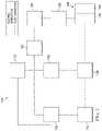
- FIG. 1is a functional block diagram of an example embodiment of a therapy system that can provide tissue treatment in accordance with this specification;
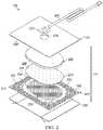
- FIG. 2is an assembly view of an example of a dressing, illustrating additional details that may be associated with some example embodiments of the therapy system of FIG. 1 ;
- FIG. 3is a schematic view of an example configuration of fluid restrictions in a layer that may be associated with some embodiments of the dressing of FIG. 2 ;
- FIG. 4is a schematic view of an example configuration of apertures in another layer, illustrating additional details that may be associated with some embodiments of the dressing of FIG. 2 ;
- FIG. 5is a schematic view of the example layer of FIG. 4 overlaid on the example layer of FIG. 3 ;
- FIG. 6is a schematic view of another example of another dressing layer, illustrating additional details that may be associated with some embodiments;
- FIG. 7 and FIG. 8illustrate other example configurations of fluid restrictions that may be associated with some embodiments of layers of the dressing of FIG. 2 ;
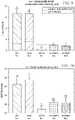
- FIG. 9is a graphical representation of maximum peel force measurements (N) on day 7 following dressing application and removal of each test and control dressing;
- FIG. 10is a graphical representation of tissue ingrowth measurements. Thickness (mm) is measured for each test and control dressing;
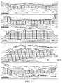
- FIG. 11is an optical micrograph picture demonstrating granulation tissue thickness for each test and control dressing.
- FIG. 12is a graphical representation of FIG. 11 demonstrating quantitative morphometry granulation tissue thickness for each test and control dressing.
- FIG. 1is a simplified functional block diagram of an example embodiment of a therapy system 100 that can provide negative-pressure therapy with instillation of topical treatment solutions to a tissue site in accordance with this specification.
- tissue sitein this context broadly refers to a wound, defect, or other treatment target located on or within tissue, including but not limited to, a surface wound, bone tissue, adipose tissue, muscle tissue, neural tissue, dermal tissue, vascular tissue, connective tissue, cartilage, tendons, or ligaments.
- tissue sitemay also refer to areas of any tissue that are not necessarily wounded or defective, but are instead areas in which it may be desirable to add or promote the growth of additional tissue. For example, negative pressure may be applied to a tissue site to grow additional tissue that may be harvested and transplanted.
- a surface woundis a wound on the surface of a body that is exposed to the outer surface of the body, such an injury or damage to the epidermis, dermis, and/or subcutaneous layers.
- Surface woundsmay include ulcers or closed incisions, for example.
- a surface wound, as used herein,does not include wounds within an intra-abdominal cavity.
- a woundmay include chronic, acute, traumatic, subacute, and dehisced wounds, partial-thickness burns, ulcers (such as diabetic, pressure, or venous insufficiency ulcers), flaps, and grafts, for example.
- the therapy system 100may include a source or supply of negative pressure, such as a negative-pressure source 102 , a dressing 104 , a fluid container, such as a container 106 , and a regulator or controller, such as a controller 108 , for example. Additionally, the therapy system 100 may include sensors to measure operating parameters and provide feedback signals to the controller 108 indicative of the operating parameters. As illustrated in FIG. 1 , for example, the therapy system 100 may include a pressure sensor 110 , an electric sensor 112 , or both, coupled to the controller 108 . As illustrated in the example of FIG. 1 , the dressing 104 may comprise or consist essentially of one or more dressing layers, such as a tissue interface 114 , a cover 116 , or both in some embodiments.
- the therapy system 100may also include a source of instillation solution.
- a solution source 118may be fluidly coupled to the dressing 104 , as illustrated in the example embodiment of FIG. 1 .
- the solution source 118may be fluidly coupled to a positive-pressure source such as the positive-pressure source 120 , a negative-pressure source such as the negative-pressure source 102 , or both in some embodiments.
- a regulatorsuch as an instillation regulator 122 , may also be fluidly coupled to the solution source 118 and the dressing 104 to ensure proper dosage of instillation solution (e.g. saline) to a tissue site.
- the instillation regulator 122may comprise a piston that can be pneumatically actuated by the negative-pressure source 102 to draw instillation solution from the solution source during a negative-pressure interval and to instill the solution to a dressing during a venting interval.
- the controller 108may be coupled to the negative-pressure source 102 , the positive-pressure source 120 , or both, to control dosage of instillation solution to a tissue site.
- the instillation regulator 122may also be fluidly coupled to the negative-pressure source 102 through the dressing 104 , as illustrated in the example of FIG. 1 .
- Some components of the therapy system 100may be housed within or used in conjunction with other components, such as sensors, processing units, alarm indicators, memory, databases, software, display devices, or user interfaces that further facilitate therapy.
- the negative-pressure source 102may be combined with the solution source 118 , the controller 108 and other components into a therapy unit.
- components of the therapy system 100may be coupled directly or indirectly.
- the negative-pressure source 102may be directly coupled to the container 106 , and may be indirectly coupled to the dressing 104 through the container 106 .
- Couplingmay include fluid, mechanical, thermal, electrical, or chemical coupling (such as a chemical bond), or some combination of coupling in some contexts.
- the negative-pressure source 102may be electrically coupled to the controller 108 .
- the negative-pressure sourcemaybe fluidly coupled to one or more distribution components, which provide a fluid path to a tissue site.
- componentsmay also be coupled by virtue of physical proximity, being integral to a single structure, or being formed from the same piece of material.
- a distribution componentis preferably detachable, and may be disposable, reusable, or recyclable.
- the dressing 104 and the container 106are illustrative of distribution components.
- a fluid conductoris another illustrative example of a distribution component.
- a tubeis an elongated, cylindrical structure with some flexibility, but the geometry and rigidity may vary.
- some fluid conductorsmay be molded into or otherwise integrally combined with other components.
- Distribution componentsmay also include or comprise interfaces or fluid ports to facilitate coupling and de-coupling other components, including sensors and data communication devices.
- a dressing interfacemay facilitate coupling a fluid conductor to the dressing 104 .
- such a dressing interfacemay be a SENSAT.R.A.C.TM Pad available from KCI of San Antonio, Tex.
- a negative-pressure supplysuch as the negative-pressure source 102
- Negative pressuregenerally refers to a pressure less than a local ambient pressure, such as the ambient pressure in a local environment external to a sealed therapeutic environment. In many cases, the local ambient pressure may also be the atmospheric pressure at which a tissue site is located. Alternatively, the pressure may be less than a hydrostatic pressure associated with tissue at the tissue site. Unless otherwise indicated, values of pressure stated herein are gauge pressures.
- references to increases in negative pressuretypically refer to a decrease in absolute pressure, while decreases in negative pressure typically refer to an increase in absolute pressure.
- the pressureis generally a low vacuum, also commonly referred to as a rough vacuum, between ⁇ 5 mm Hg ( ⁇ 667 Pa) and ⁇ 500 mm Hg ( ⁇ 66.7 kPa).
- Common therapeutic rangesare between ⁇ 50 mm Hg ( ⁇ 9.9 kPa) and ⁇ 300 mm Hg ( ⁇ 39.9 kPa).
- the container 106is representative of a container, canister, pouch, or other storage component, which can be used to manage exudates and other fluids withdrawn from a tissue site.
- a rigid containermay be preferred or required for collecting, storing, and disposing of fluids.
- fluidsmay be properly disposed of without rigid container storage, and a re-usable container could reduce waste and costs associated with negative-pressure therapy.
- a controllersuch as the controller 108
- the controller 108may be a microcontroller, which generally comprises an integrated circuit containing a processor core and a memory programmed to directly or indirectly control one or more operating parameters of the therapy system 100 . Operating parameters may include the power applied to the negative-pressure source 102 , the pressure generated by the negative-pressure source 102 , or the pressure distributed to the tissue interface 114 , for example.
- the controller 108is also preferably configured to receive one or more input signals, such as a feedback signal, and programmed to modify one or more operating parameters based on the input signals.
- Sensorssuch as the pressure sensor 110 or the electric sensor 112 , are generally known in the art as any apparatus operable to detect or measure a physical phenomenon or property, and generally provide a signal indicative of the phenomenon or property that is detected or measured.
- the pressure sensor 110 and the electric sensor 112may be configured to measure one or more operating parameters of the therapy system 100 .
- the pressure sensor 110may be a transducer configured to measure pressure in a pneumatic pathway and convert the measurement to a signal indicative of the pressure measured.
- the pressure sensor 110may be a piezo-resistive strain gauge.
- the electric sensor 112may optionally measure operating parameters of the negative-pressure source 102 , such as the voltage or current, in some embodiments.
- the signals from the pressure sensor 110 and the electric sensor 112are suitable as an input signal to the controller 108 , but some signal conditioning may be appropriate in some embodiments.
- the signalmay need to be filtered or amplified before it can be processed by the controller 108 .
- the signalis an electrical signal, but may be represented in other forms, such as an optical signal.
- the tissue interface 114can be generally adapted to contact a tissue site.
- the tissue interface 114may be partially or fully in contact with the tissue site. If the tissue site is a wound, for example, the tissue interface 114 may partially or completely fill the wound, or may be placed over the wound.
- the tissue interface 114may take many forms and have more than one layer in some embodiments.
- the tissue interface 114may also have many sizes, shapes, or thicknesses depending on a variety of factors, such as the type of treatment being implemented or the nature and size of a tissue site. For example, the size and shape of the tissue interface 114 may be adapted to the contours of deep and irregular shaped tissue sites.
- the cover 116may provide a bacterial barrier and protection from physical trauma.
- the cover 116may also be constructed from a material that can reduce evaporative losses and provide a fluid seal between two components or two environments, such as between a therapeutic environment and a local external environment.
- the cover 116may be, for example, an elastomeric film or membrane that can provide a seal adequate to maintain a negative pressure at a tissue site for a given negative-pressure source.
- the cover 116may have a high moisture-vapor transmission rate (MVTR) in some applications.
- the MVTRmay be at least 300 g/m ⁇ circumflex over ( ) ⁇ 2 per twenty-four hours in some embodiments.
- the cover 116may be a polymer drape, such as a polyurethane film, that is permeable to water vapor but impermeable to liquid.
- a polymer drapesuch as a polyurethane film
- Such drapestypically have a thickness in the range of 25-50 microns.
- the permeabilitygenerally should be low enough that a desired negative pressure may be maintained.
- the cover 116may comprise, for example, one or more of the following materials: hydrophilic polyurethane; cellulosics; hydrophilic polyamides; polyvinyl alcohol; polyvinyl pyrrolidone; hydrophilic acrylics; hydrophilic silicone elastomers; an INSPIRE 2301 material from Coveris Advanced Coatings of Wrexham, United Kingdom having, for example, an MVTR (inverted cup technique) of 14400 g/m 2 /24 hours and a thickness of about 30 microns; a thin, uncoated polymer drape; natural rubbers; polyisoprene; styrene butadiene rubber; chloroprene rubber; polybutadiene; nitrile rubber; butyl rubber; ethylene propylene rubber; ethylene propylene diene monomer; chlorosulfonated polyethylene; polysulfide rubber; polyurethane (PU); EVA film; co-polyester; silicones; a silicone drape; a 3
- An attachment devicemay be used to attach the cover 116 to an attachment surface, such as undamaged epidermis, a gasket, or another cover.
- the attachment devicemay take many forms.
- an attachment devicemay be a medically-acceptable, pressure-sensitive adhesive configured to bond the cover 116 to epidermis around a tissue site, such as a surface wound.
- some or all of the cover 116may be coated with an adhesive, such as an acrylic adhesive, which may have a coating weight between 25-65 grams per square meter (g.s.m.). Thicker adhesives, or combinations of adhesives, may be applied in some embodiments to improve the seal and reduce leaks.
- Other example embodiments of an attachment devicemay include a double-sided tape, paste, hydrocolloid, hydrogel, silicone gel, or organogel.
- the solution source 118may also be representative of a container, canister, pouch, bag, or other storage component, which can provide a solution for instillation therapy.
- Compositions of solutionsmay vary according to a prescribed therapy, but examples of solutions that may be suitable for some prescriptions include hypochlorite-based solutions, silver nitrate (0.5%), sulfur-based solutions, biguanides, cationic solutions, and isotonic solutions.
- the fluid mechanics of using a negative-pressure source to reduce pressure in another component or location, such as within a sealed therapeutic environment,can be mathematically complex.
- the basic principles of fluid mechanics applicable to negative-pressure therapy and instillationare generally well-known to those skilled in the art, and the process of reducing pressure may be described illustratively herein as “delivering,” “distributing,” or “generating” negative pressure, for example.
- exudates and other fluidsflow toward lower pressure along a fluid path.
- downstreamtypically implies something in a fluid path relatively closer to a source of negative pressure or further away from a source of positive pressure.
- upstreamimplies something relatively further away from a source of negative pressure or closer to a source of positive pressure.
- outletor outlet in such a frame of reference. This orientation is generally presumed for purposes of describing various features and components herein.
- the fluid pathmay also be reversed in some applications (such as by substituting a positive-pressure source for a negative-pressure source) and this descriptive convention should not be construed as a limiting convention.
- FIG. 2is an assembly view of an example of the dressing 104 of FIG. 1 , illustrating additional details that may be associated with some embodiments in which the tissue interface 114 comprises more than one layer.
- the tissue interface 114comprises a first layer 205 , a second layer 210 , and a third layer 215 .
- the first layer 205may be disposed adjacent to a second layer 210
- the third layer 215may be disposed adjacent to the second layer 210 opposite the first layer 205 .
- first layer 205 , the second layer 210 , and the third layer 215may be stacked so that the first layer 205 is in contact with the second layer 210 , and the second layer 210 is in contact with the first layer 205 and the third layer 215 .
- One or more of the first layer 205 , the second layer 210 , and the third layer 215may also be bonded to an adjacent layer in some embodiments.
- the first layer 205may comprise or consist essentially of a manifold or manifold layer, which provides a means for collecting or distributing fluid across the tissue interface 114 under pressure.
- the first layer 205may be adapted to receive negative pressure from a source and distribute negative pressure through multiple apertures across the tissue interface 114 , which may have the effect of collecting fluid from across a tissue site and drawing the fluid toward the source.
- the fluid pathmay be reversed or a secondary fluid path may be provided to facilitate delivering fluid, such as from a source of instillation solution, across the tissue interface 114 .
- the first layer 205may comprise a plurality of pathways, which can be interconnected to improve distribution or collection of fluids.
- the first layer 205may comprise or consist essentially of a porous material having interconnected fluid pathways.
- open-cell foam, reticulated foam, porous tissue collections, and other porous materialsuch as gauze or felted mat generally include pores, edges, and/or walls adapted to form interconnected fluid channels.
- Liquids, gels, and other foamsmay also include or be cured to include apertures and fluid pathways.
- the first layer 205may additionally or alternatively comprise projections that form interconnected fluid pathways.
- the first layer 205may be molded to provide surface projections that define interconnected fluid pathways. Any or all of the surfaces of the first layer 205 may have an uneven, coarse, or jagged profile
- the first layer 205may comprise or consist essentially of a reticulated foam having pore sizes and free volume that may vary according to needs of a prescribed therapy.
- a reticulated foam having a free volume of at least 90%may be suitable for many therapy applications, and a foam having an average pore size in a range of 400-600 microns (40-50 pores per inch) may be particularly suitable for some types of therapy.
- the tensile strength of the first layer 205may also vary according to needs of a prescribed therapy. For example, the tensile strength of a foam may be increased for instillation of topical treatment solutions.
- the 25% compression load deflection of the first layer 205may be at least 0.35 pounds per square inch, and the 65% compression load deflection may be at least 0.43 pounds per square inch.
- the tensile strength of the first layer 205may be at least 10 pounds per square inch.
- the first layer 205may have a tear strength of at least 2.5 pounds per inch.
- the first layer 205may be a foam comprised of polyols such as polyester or polyether, isocyanate such as toluene diisocyanate, and polymerization modifiers such as amines and tin compounds.
- the first layer 205may be a reticulated polyurethane ether foam such as used in GRANUFOAMTM dressing or V.A.C. VERAFLOTM dressing, both available from KCI of San Antonio, Tex.
- the thickness of the first layer 205may also vary according to needs of a prescribed therapy. For example, the thickness of the first layer 205 may be decreased to relieve stress on other layers and to reduce tension on peripheral tissue. The thickness of the first layer 205 can also affect the conformability of the first layer 205 . In some embodiments, a thickness in a range of about 5 millimeters to 10 millimeters may be suitable.
- the second layer 210may comprise or consist essentially of a means for controlling or managing fluid flow.
- the second layermay comprise or consist essentially of a liquid-impermeable, elastomeric material.
- the second layer 210may comprise or consist essentially of a polymer film.
- the second layer 210may also have a smooth or matte surface texture in some embodiments. A glossy or shiny finish better or equal to a grade B3 according to the SPI (Society of the Plastics Industry) standards may be particularly advantageous for some applications.
- variations in surface heightmay be limited to acceptable tolerances.
- the surface of the second layermay have a substantially flat surface, with height variations limited to 0.2 millimeters over a centimeter.
- the second layer 210may be hydrophobic.
- the hydrophobicity of the second layer 210may vary, but may have a contact angle with water of at least ninety degrees in some embodiments.
- the second layer 210may have a contact angle with water of no more than 150 degrees.
- the contact angle of the second layer 210may be in a range of at least 90 degrees to about 120 degrees, or in a range of at least 120 degrees to 150 degrees. Water contact angles can be measured using any standard apparatus.
- contact angle measuring instrumentscan often include an integrated system involving a level stage, liquid dropper such as a syringe, camera, and software designed to calculate contact angles more accurately and precisely, among other things.
- integrated systemsmay include the FTA125, FTA200, FTA2000, and FTA4000 systems, all commercially available from First Ten Angstroms, Inc., of Portsmouth, Va., and the DTA25, DTA30, and DTA100 systems, all commercially available from Kruss GmbH of Hamburg, Germany.
- water contact angles hereinare measured using deionized and distilled water on a level sample surface for a sessile drop added from a height of no more than 5 cm in air at 20-25° C. and 20-50% relative humidity. Contact angles reported herein represent averages of 5-9 measured values, discarding both the highest and lowest measured values.
- the hydrophobicity of the second layer 210may be further enhanced with a hydrophobic coating of other materials, such as silicones and fluorocarbons, either as coated from a liquid, or plasma coated.
- the second layer 210may also be suitable for welding to other layers, including the first layer 205 .
- the second layer 210may be adapted for welding to polyurethane foams using heat, radio frequency (RF) welding, or other methods to generate heat such as ultrasonic welding.
- RF weldingmay be particularly suitable for more polar materials, such as polyurethane, polyamides, polyesters and acrylates. Sacrificial polar interfaces may be used to facilitate RF welding of less polar film materials, such as polyethylene.
- the area density of the second layer 210may vary according to a prescribed therapy or application. In some embodiments, an area density of less than 40 grams per square meter may be suitable, and an area density of about 20-30 grams per square meter may be particularly advantageous for some applications.
- the second layer 210may comprise or consist essentially of a hydrophobic polymer, such as a polyethylene film.
- a hydrophobic polymersuch as a polyethylene film.
- the simple and inert structure of polyethylenecan provide a surface that interacts little, if any, with biological tissues and fluids, providing a surface that may encourage the free flow of liquids and low adherence, which can be particularly advantageous for many applications.
- More polar films suitable for laminating to a polyethylene filminclude polyamide, co-polyesters, ionomers, and acrylics.
- tie layersmay be used, such as ethylene vinyl acetate, or modified polyurethanes.
- An ethyl methyl acrylate (EMA) filmmay also have suitable hydrophobic and welding properties for some configurations.
- the second layer 210may have one or more fluid restrictions 220 , which can be distributed uniformly or randomly across the second layer 210 .
- the fluid restrictions 220may be bi-directional and pressure-responsive.
- the fluid restrictions 220can generally comprise or consist essentially of an elastic passage that is normally unstrained to substantially reduce liquid flow, and can expand in response to a pressure gradient.
- the fluid restrictions 220may comprise or consist essentially of perforations in the second layer 210 . Perforations may be formed by removing material from the second layer 210 . For example, perforations may be formed by cutting through the second layer 210 , which may also deform the edges of the perforations in some embodiments.
- the passagesmay be sufficiently small to form a seal or flow restriction, which can substantially reduce or prevent liquid flow.
- one or more of the fluid restrictions 220may be an elastomeric valve that is normally closed when unstrained to substantially prevent liquid flow, and can open in response to a pressure gradient.
- a fenestration in the second layer 210may be a suitable valve for some applications. Fenestrations may also be formed by removing material from the second layer 210 , but the amount of material removed and the resulting dimensions of the fenestrations may be an order of magnitude less than perforations, and may not deform the edges.
- the fluid restrictions 220may comprise or consist essentially of one or more slots or combinations of slots in the second layer 210 .
- the fluid restrictions 220may comprise or consist of linear slots having a length less than 4 millimeters and a width less than 1 millimeter. The length may be at least 2 millimeters, and the width may be at least 0.4 millimeters in some embodiments. A length of about 3 millimeters and a width of about 0.8 millimeter may be particularly suitable for many applications. A tolerance of about 0.1 millimeter may also be acceptable. Such dimensions and tolerances may be achieved with a laser cutter, for example. Slots of such configurations may function as imperfect valves that substantially reduce liquid flow in a normally closed or resting state. For example, such slots may form a flow restriction without being completely closed or sealed. The slots can expand or open wider in response to a pressure gradient to allow increased liquid flow.
- the third layer 215may be a sealing layer comprising or consisting essentially of a soft, pliable material suitable for providing a fluid seal with a tissue site, and may have a substantially flat surface.
- the third layer 215may comprise, without limitation, a silicone gel, a soft silicone, hydrocolloid, hydrogel, polyurethane gel, polyolefin gel, hydrogenated styrenic copolymer gel, a foamed gel, a soft closed cell foam such as polyurethanes and polyolefins coated with an adhesive, polyurethane, polyolefin, or hydrogenated styrenic copolymers.
- the third layer 215may have a thickness between about 200 microns ( ⁇ m) and about 1000 microns ( ⁇ m). In some embodiments, the third layer 215 may have a hardness between about 5 Shore OO and about 80 Shore OO. Further, the third layer 215 may be comprised of hydrophobic or hydrophilic materials.
- the third layer 215may be a hydrophobic-coated material.
- the third layer 215may be formed by coating a spaced material, such as, for example, woven, nonwoven, molded, or extruded mesh with a hydrophobic material.
- the hydrophobic material for the coatingmay be a soft silicone, for example.
- the third layer 215may have a periphery 225 surrounding or around an interior portion 230 , and apertures 235 disposed through the periphery 225 and the interior portion 230 .
- the interior portion 230may correspond to a surface area of the first layer 205 in some examples.
- the third layer 215may also have corners 240 and edges 245 .
- the corners 240 and the edges 245may be part of the periphery 225 .
- the third layer 215may have an interior border 250 around the interior portion 230 , disposed between the interior portion 230 and the periphery 225 .
- the interior border 250may be substantially free of the apertures 235 , as illustrated in the example of FIG. 2 .
- the interior portion 230may be symmetrical and centrally disposed in the third layer 215 .
- the apertures 235may be formed by cutting or by application of local RF or ultrasonic energy, for example, or by other suitable techniques for forming an opening.
- the apertures 235may have a uniform distribution pattern, or may be randomly distributed on the third layer 215 .
- the apertures 235 in the third layer 215may have many shapes, including circles, squares, stars, ovals, polygons, slits, complex curves, rectilinear shapes, triangles, for example, or may have some combination of such shapes.
- each of the apertures 235may have uniform or similar geometric properties.
- each of the apertures 235may be circular apertures, having substantially the same diameter.
- the diameter of each of the apertures 235may be between about 1 millimeter to about 50 millimeters. In other embodiments, the diameter of each of the apertures 235 may be between about 1 millimeter to about 20 millimeters.
- geometric properties of the apertures 235may vary.
- the diameter of the apertures 235may vary depending on the position of the apertures 235 in the third layer 215 , as illustrated in FIG. 2 .
- the diameter of the apertures 235 in the periphery 225 of the third layer 215may be larger than the diameter of the apertures 235 in the interior portion 230 of the third layer 215 .
- the apertures 235 disposed in the periphery 225may have a diameter between about 9.8 millimeters to about 10.2 millimeters.
- the apertures 235 disposed in the corners 240may have a diameter between about 7.75 millimeters to about 8.75 millimeters.
- the apertures 235 disposed in the interior portion 230may have a diameter between about 1.8 millimeters to about 2.2 millimeters.
- At least one of the apertures 235 in the periphery 225 of the third layer 215may be positioned at the edges 245 of the periphery 225 , and may have an interior cut open or exposed at the edges 245 that is in fluid communication in a lateral direction with the edges 245 .
- the lateral directionmay refer to a direction toward the edges 245 and in the same plane as the third layer 215 .
- the apertures 235 in the periphery 225may be positioned proximate to or at the edges 245 and in fluid communication in a lateral direction with the edges 245 .
- the apertures 235 positioned proximate to or at the edges 245may be spaced substantially equidistant around the periphery 225 as shown in the example of FIG. 2 .
- the spacing of the apertures 235 proximate to or at the edges 245may be irregular.
- the dressing 104may further include an attachment device, such as an adhesive 255 .
- the adhesive 255may be, for example, a medically-acceptable, pressure-sensitive adhesive that extends about a periphery, a portion, or the entire cover 116 .
- the adhesive 255may be an acrylic adhesive having a coating weight between 25-65 grams per square meter (g.s.m.). Thicker adhesives, or combinations of adhesives, may be applied in some embodiments to improve the seal and reduce leaks.
- the adhesive 255may be a layer having substantially the same shape as the periphery 225 . In some embodiments, such a layer of the adhesive 255 may be continuous or discontinuous.
- Discontinuities in the adhesive 255may be provided by apertures or holes (not shown) in the adhesive 136 .
- the apertures or holes in the adhesive 255may be formed after application of the adhesive 255 or by coating the adhesive 255 in patterns on a carrier layer, such as, for example, a side of the cover 116 .
- Apertures or holes in the adhesive 255may also be sized to enhance the MVTR of the dressing 104 in some example embodiments.
- a release liner 260may be attached to or positioned adjacent to the third layer 215 to protect the adhesive 255 prior to use.
- the release liner 260may also provide stiffness to assist with, for example, deployment of the dressing 104 .
- the release liner 260may be, for example, a casting paper, a film, or polyethylene.
- the release liner 260may be a polyester material such as polyethylene terephthalate (PET), or similar polar semi-crystalline polymer.
- PETpolyethylene terephthalate
- the use of a polar semi-crystalline polymer for the release liner 260may substantially preclude wrinkling or other deformation of the dressing 104 .
- the polar semi-crystalline polymermay be highly orientated and resistant to softening, swelling, or other deformation that may occur when brought into contact with components of the dressing 104 , or when subjected to temperature or environmental variations, or sterilization.
- the release liner 260may have a surface texture that may be imprinted on an adjacent layer, such as the third layer 215 .
- a release agentmay be disposed on a side of the release liner 260 that is configured to contact the third layer 215 .
- the release agentmay be a silicone coating and may have a release factor suitable to facilitate removal of the release liner 260 by hand and without damaging or deforming the dressing 104 .
- the release agentmay be a fluorocarbon or a fluorosilicone, for example.
- the release liner 260may be uncoated or otherwise used without a release agent.
- FIG. 2also illustrates one example of a fluid conductor 265 and a dressing interface 270 .
- the fluid conductor 265may be a flexible tube, which can be fluidly coupled on one end to the dressing interface 270 .
- the dressing interface 270may be an elbow connector, as shown in the example of FIG. 2 , which can be placed over an aperture 275 in the cover 116 to provide a fluid path between the fluid conductor 265 and the tissue interface 114 .
- FIG. 3is a schematic view of an example of the second layer 210 , illustrating additional details that may be associated with some embodiments.
- the fluid restrictions 220may each consist essentially of one or more linear slots having a length of about 3 millimeters.
- FIG. 3additionally illustrates an example of a uniform distribution pattern of the fluid restrictions 220 .
- the fluid restrictions 220are substantially coextensive with the second layer 210 , and are distributed across the second layer 210 in a grid of parallel rows and columns, in which the slots are also mutually parallel to each other.
- the rowsmay be spaced about 3 millimeters on center, and the fluid restrictions 220 within each of the rows may be spaced about 3 millimeters on center as illustrated in the example of FIG. 3 .
- the fluid restrictions 220 in adjacent rowsmay be aligned or offset.
- adjacent rowsmay be offset, as illustrated in FIG. 3 , so that the fluid restrictions 220 are aligned in alternating rows and separated by about 6 millimeters.
- the spacing of the fluid restrictions 220may vary in some embodiments to increase the density of the fluid restrictions 220 according to therapeutic requirements.
- FIG. 4is a schematic view of an example configuration of the apertures 235 , illustrating additional details that may be associated with some embodiments of the third layer 215 .
- the apertures 235 illustrated in FIG. 4may be associated only with the interior portion 230 .
- the apertures 235are generally circular and have a diameter of about 2 millimeters.
- FIG. 4also illustrates an example of a uniform distribution pattern of the apertures 235 in the interior portion 230 .
- the apertures 235are distributed across the interior portion 230 in a grid of parallel rows and columns. Within each row and column, the apertures 235 may be equidistant from each other, as illustrated in the example of FIG. 4 .
- FIG. 4illustrates one example configuration that may be particularly suitable for many applications, in which the apertures 235 are spaced about 6 millimeters apart along each row and column, with a 3 millimeter offset.
- FIG. 5is a schematic view of the example third layer 215 of FIG. 4 overlaid on the second layer 210 of FIG. 3 , illustrating additional details that may be associated with some example embodiments of the tissue interface 114 .
- the fluid restrictions 220may be aligned, overlapping, in registration with, or otherwise fluidly coupled to the apertures 235 in some embodiments.
- one or more of the fluid restrictions 220may be registered with the apertures 235 only in the interior portion 230 , or only partially registered with the apertures 235 .
- the fluid restrictions 220 in the example of FIG. 5are generally configured so that each of the fluid restrictions 220 is registered with only one of the apertures 235 .
- one or more of the fluid restrictions 220may be registered with more than one of the apertures 235 .
- any one or more of the fluid restrictions 220may be a perforation or a fenestration that extends across two or more of the apertures 235 .
- one or more of the fluid restrictions 220may not be registered with any of the apertures 235 .
- the apertures 235may be sized to expose a portion of the second layer 210 , the fluid restrictions 220 , or both through the third layer 215 .
- each of the apertures 235may be sized to expose no more than two of the fluid restrictions 220 .
- the length of each of the fluid restrictions 220may be substantially equal to or less than the diameter of each of the apertures 235 .
- the average dimensions of the fluid restrictions 220are substantially similar to the average dimensions of the apertures 235 .
- the apertures 235may be elliptical in some embodiments, and the length of each of the fluid restrictions 220 may be substantially equal to the major axis or the minor axis. In some embodiments, though, the dimensions of the fluid restrictions 220 may exceed the dimensions of the apertures 235 , and the size of the apertures 235 may limit the effective size of the fluid restrictions 220 exposed to the lower surface of the dressing 104 .
- the first layer 205may be a foam, mesh, or non-woven coated with an antimicrobial agent.
- the first layermay comprise antimicrobial elements, such as fibers coated with an antimicrobial agent.
- some embodiments of the second layer 210may be a polymer coated or mixed with an antimicrobial agent.
- the fluid conductor 265may additionally or alternatively be treated with one or more antimicrobial agents.
- Suitable antimicrobial agentsmay include, for example, metallic silver, PHMB, iodine or its complexes and mixes such as povidone iodine, copper metal compounds, chlorhexidine, or some combination of these materials.
- Individual components of the dressing 104may be bonded or otherwise secured to one another with a solvent or non-solvent adhesive, or with thermal welding, for example, without adversely affecting fluid management.
- the second layer 210 or the first layer 205may be coupled to the border 250 of the third layer 215 in any suitable manner, such as with a weld or an adhesive, for example.
- the cover 116 , the first layer 205 , the second layer 210 , the third layer 215 , or various combinationsmay be assembled before application or in situ.
- the cover 116may be laminated to the first layer 205
- the second layer 210may be laminated to the first layer 205 opposite the cover 116 in some embodiments.
- the third layer 215may also be coupled to the second layer 210 opposite the first layer 205 in some embodiments.
- one or more layers of the tissue interface 114may coextensive.
- the first layer 205may be coextensive with the second layer 210 , as illustrated in the embodiment of FIG. 2 .
- the dressing 104may be provided as a single, composite dressing.
- the third layer 215may be coupled to the cover 116 to enclose the first layer 205 and the second layer 210 , wherein the third layer 215 is configured to face a tissue site.
- the release liner 260may be removed to expose the third layer 215 , which may be placed within, over, on, or otherwise proximate to a tissue site, particularly a surface tissue site and adjacent epidermis.
- the third layer 215 and the second layer 210may be interposed between the first layer 205 and the tissue site, which can substantially reduce or eliminate adverse interaction with the first layer 205 .
- the third layer 215may be placed over a surface wound (including edges of the wound) and undamaged epidermis to prevent direct contact with the first layer 205 .
- Treatment of a surface wound or placement of the dressing 104 on a surface woundincludes placing the dressing 104 immediately adjacent to the surface of the body or extending over at least a portion of the surface of the body. Treatment of a surface wound does not include placing the dressing 104 wholly within the body or wholly under the surface of the body, such as placing a dressing within an abdominal cavity.
- the interior portion 230 of the third layer 215may be positioned adjacent to, proximate to, or covering a tissue site.
- at least some portion of the second layer 210 , the fluid restrictions 220 , or bothmay be exposed to a tissue site through the third layer 215 .
- the periphery 225 of the third layer 215may be positioned adjacent to or proximate to tissue around or surrounding the tissue site.
- the third layer 215may be sufficiently tacky to hold the dressing 104 in position, while also allowing the dressing 104 to be removed or re-positioned without trauma to the tissue site.
- Removing the release liner 260can also expose the adhesive 255 , and the cover 116 may be attached to an attachment surface.
- the covermay be attached to epidermis peripheral to a tissue site, around the first layer 205 and the second layer 210 .
- the adhesive 255may be in fluid communication with an attachment surface through the apertures 235 in at least the periphery 225 of the third layer 215 in some embodiments.
- the adhesive 255may also be in fluid communication with the edges 245 through the apertures 235 exposed at the edges 245 .
- the adhesive 255may be pressed through the apertures 235 to bond the dressing 104 to the attachment surface.
- the apertures 235 at the edges 245may permit the adhesive 255 to flow around the edges 245 for enhancing the adhesion of the edges 159 to an attachment surface.
- apertures or holes in the third layer 215may be sized to control the amount of the adhesive 255 in fluid communication with the apertures 235 .
- the relative sizes of the apertures 235may be configured to maximize the surface area of the adhesive 255 exposed and in fluid communication through the apertures 235 at the corners 240 .
- the edges 245may intersect at substantially a right angle, or about 90 degrees, to define the corners 240 .
- the corners 240may have a radius of about 10 millimeters.
- three of the apertures 235 having a diameter between about 7.75 millimeters to about 8.75 millimetersmay be positioned in a triangular configuration at the corners 240 to maximize the exposed surface area for the adhesive 255 .
- the size and number of the apertures 235 in the corners 240may be adjusted as necessary, depending on the chosen geometry of the corners 240 , to maximize the exposed surface area of the adhesive 255 .
- the apertures 235 at the corners 240may be fully housed within the third layer 215 , substantially precluding fluid communication in a lateral direction exterior to the corners 240 .
- the apertures 235 at the corners 240 being fully housed within the third layer 215may substantially preclude fluid communication of the adhesive 255 exterior to the corners 240 , and may provide improved handling of the dressing 104 during deployment at a tissue site. Further, the exterior of the corners 240 being substantially free of the adhesive 136 may increase the flexibility of the corners 240 to enhance comfort.
- the bond strength of the adhesive 255may vary in different locations of the dressing 104 .
- the adhesive 255may have a lower bond strength in locations adjacent to the third layer 215 where the apertures 235 are relatively larger, and may have a higher bond strength where the apertures 235 are smaller.
- Adhesive 255 with lower bond strength in combination with larger apertures 235may provide a bond comparable to adhesive 255 with higher bond strength in locations having smaller apertures 235 .
- the geometry and dimensions of the tissue interface 114 , the cover 116 , or bothmay vary to suit a particular application or anatomy.
- the geometry or dimensions of the tissue interface 114 and the cover 116may be adapted to provide an effective and reliable seal against challenging anatomical surfaces, such as an elbow or heel, at and around a tissue site.
- the dimensionsmay be modified to increase the surface area for the third layer 215 to enhance the movement and proliferation of epithelial cells at a tissue site and reduce the likelihood of granulation tissue in-growth.
- the dressing 104may permit re-application or re-positioning to reduce or eliminate leaks, which can be caused by creases and other discontinuities in the dressing 104 and a tissue site.
- the ability to rectify leaksmay increase the reliability of the therapy and reduce power consumption in some embodiments.
- the dressing 104 in the example of FIG. 2can provide a sealed therapeutic environment proximate to a tissue site, substantially isolated from the external environment, and the negative-pressure source 102 can reduce the pressure in the sealed therapeutic environment.
- the third layer 215may provide an effective and reliable seal against challenging anatomical surfaces, such as an elbow or heel, at and around a tissue site.
- the dressing 104may permit re-application or re-positioning, to correct air leaks caused by creases and other discontinuities in the dressing 104 , for example.
- the ability to rectify leaksmay increase the efficacy of the therapy and reduce power consumption in some embodiments.
- the dressing interface 270may disposed over the aperture 275 and attached to the cover 116 .
- the fluid conductor 265may be fluidly coupled to the dressing interface 270 and to the negative-pressure source 102 .
- Negative pressure applied through the tissue interface 114can create a negative pressure differential across the fluid restrictions 220 in the second layer 210 , which can open or expand the fluid restrictions 220 from their resting state.
- a pressure gradient across the fenestrationscan strain the adjacent material of the second layer 210 and increase the dimensions of the fenestrations to allow liquid movement through them, similar to the operation of a duckbill valve. Opening the fluid restrictions 220 can allow exudate and other liquid movement through the fluid restrictions 220 into the first layer 205 and the container 106 .
- Changes in pressurecan also cause the first layer 205 to expand and contract, and the interior border 250 may protect the epidermis from irritation.
- the second layer 210 and the third layer 215can also substantially reduce or prevent exposure of tissue to the first layer 205 , which can inhibit growth of tissue into the first layer 205 .
- the first layer 205may be hydrophobic to minimize retention or storage of liquid in the dressing 104 .
- the first layer 205may be hydrophilic.
- the first layer 205may also wick fluid away from a tissue site, while continuing to distribute negative pressure to the tissue site. The wicking properties of the first layer 205 may draw fluid away from a tissue site by capillary flow or other wicking mechanisms, for example.
- An example of a hydrophilic first layer 205is a polyvinyl alcohol, open-cell foam such as V.A.C. WHITEFOAMTM dressing available from KCI of San Antonio, Tex.
- Other hydrophilic foamsmay include those made from polyether.
- Other foams that may exhibit hydrophilic characteristicsinclude hydrophobic foams that have been treated or coated to provide hydrophilicity.
- the pressure differential across the fluid restrictions 220can dissipate, allowing the fluid restrictions 220 to move to their resting state and prevent or reduce the rate at which exudate or other liquid from returning to the tissue site through the second layer 210 .
- a fillermay also be disposed between a tissue site and the third layer 215 .
- a tissue siteis a surface wound
- a wound fillermay be applied interior to the periwound
- the third layer 215may be disposed over the periwound and the wound filler.
- the fillermay be a manifold, such as an open-cell foam.
- the fillermay comprise or consist essentially of the same material as the first layer 205 in some embodiments.
- instillation solution or other fluidmay be distributed to the dressing 104 , which can increase the pressure in the tissue interface 114 .
- the increased pressure in the tissue interface 114can create a positive pressure differential across the fluid restrictions 220 in the second layer 210 , which can open or expand the fluid restrictions 220 from their resting state to allow the instillation solution or other fluid to be distributed to the tissue site.
- FIG. 6is a schematic view of another example of the third layer 215 , illustrating additional details that may be associated with some embodiments.
- the third layer 215may have one or more fluid restrictions, such as valves 605 , instead of or in addition to the apertures 235 in the interior portion 230 .
- the valves 605may be included in the third layer 215 in addition to or instead of the fluid restrictions 220 in the second layer 210 .
- the second layer 210may be omitted.
- the tissue interface 114may consist essentially of the first layer 205 and the third layer 215 of FIG. 6 with the valves 605 disposed in the interior portion 230 .
- FIG. 7 and FIG. 8illustrate other example configurations of the valves 605 , in which the valves 605 each generally comprise a combination of intersecting slits or cross-slits.
- Methods of treating a surface wound to promote healing and tissue granulationmay include applying the dressing 104 to a surface wound and sealing the dressing 104 to epidermis adjacent to the surface wound.
- the third layer 215may be placed over the surface wound, covering at least a portion of the edge of the surface wound and a periwound adjacent to the surface wound.
- the covermay also be attached to epidermis around the third layer 215 .
- the dressing 104may be fluidly coupled to a negative-pressure source, such as the negative-pressure source 102 . Negative pressure from the negative-pressure source may be applied to the dressing 104 , opening the fluid restrictions 220 .
- the fluid restrictions 220can be closed by blocking, stopping, or reducing the negative pressure.
- the second layer 210 and the third layer 215can substantially prevent exposure of tissue in the surface wound to the first layer 205 , inhibiting growth of tissue into the first layer 205 .
- the dressing 104can also substantially prevent maceration of the periwound.
- the systems, apparatuses, and methods described hereinmay provide significant advantages over prior dressings.
- some dressings for negative-pressure therapycan require time and skill to be properly sized and applied to achieve a good fit and seal.
- some embodiments of the dressing 104provide a negative-pressure dressing that is simple to apply, reducing the time to apply and remove.
- the dressing 104may be a fully-integrated negative-pressure therapy dressing that can be applied to a tissue site (including on the periwound) in one step, without being cut to size, while still providing or improving many benefits of other negative-pressure therapy dressings that require sizing.
- Such benefitsmay include good manifolding, beneficial granulation, protection of the peripheral tissue from maceration, and a low-trauma and high-seal bond. These characteristics may be particularly advantageous for surface wounds having moderate depth and medium-to-high levels of exudate.
- Some embodiments of the dressing 104may remain on the tissue site for at least 5 days, and some embodiments may remain for at least 7 days.
- Antimicrobial agents in the dressing 104may extend the usable life of the dressing 104 by reducing or eliminating infection risks that may be associated with extended use, particularly use with infected or highly exuding wounds.
- the primary objective of this studywas to evaluate an embodiment of a dressing having features described above (designated as “GM” for purposes of the study), in conjunction with V.A.C.® Therapy and V.A.C. VERAFLOTM Therapy as compared to traditional V.A.C.® Therapy with GRANUFOAMTM dressing and to other Advanced Wound Care dressings without V.A.C.® Therapy.
- Woundswere assessed for granulation tissue formation, presence of maceration in periwound skin and ease of dressing removal as determined by:
- the initial pilot animal(Group 1) underwent all wound creation and therapy prior to scheduling procedures on the additional Group 2 and 3 animals.
- Up to Ten (10) full thickness skin excisional wounds( ⁇ 3 ⁇ 7.5 cm) were created on each animal (up to 5 wounds on each side of the spine) with the aid of a sterile template. There was spacing between each of the wounds (approximately 6 cm or more from wound edge to wound edge between adjacent wounds, and sufficient spacing between all wounds to provide enough space to properly place the dressings and the drape. If the length of the back of the animal did not provide enough space for 10 wounds and dressings (determined on Day 0) then 8 wounds (4 on each side of spine) was created.
- a scalpel bladewas used to surgically create the wound down to the subcutaneous fascial layer (just over the muscle) but without disrupting it. If disruption of the subcutaneous fascial layer occurred, it was documented in the study records. Care was taken during wound creation so as not to undermine the perimeter of the wound.
- the woundswere prepared in two paraspinal columns with efforts made to keep the columns between the crest of the shoulders and the coccygeal tuberosity. Direct pressure with sterile gauze was utilized to obtain hemostasis. In the event of excessive bleeding that did not subside with direct pressure, a hemostat was used to clamp the source of bleeding. Wound sites were kept moist with sterile 0.9% saline-soaked gauze during the creation of other wounds. Wounds were photographed.
- the periwound areawas wiped clean with sterile 0.9% saline-soaked gauze and allowed to dry. Dressings were applied to the individual wound sites per a randomization scheme.
- An adhesive such as benzoinwas placed on the skin surrounding the very perimeter of the test article edges, regardless of the type of dressing for a particular wound, so that the periwound area was framed with adhesive leaving a ⁇ 1 cm perimeter of periwound free of benzoin. This means that the immediate periwound skin cannot have benzoin adhesive applied as this may affect the EpiD readings.
- the adhesivewas placed on the skin in any area that V.A.C.® Drape was applied.
- Hollistera medical grade silicone adhesive was applied as an extra adhesive to help maintain a seal.
- test article wound pairtest article with V.A.C.® Therapy
- test article with V.A.C. VERAFLOTM Therapytest article using V.A.C. VERAFLOTM Therapy with saline
- a pair of electrodese.g. aluminum sheet or wire
- V.A.C.® DrapeAs applicable, the skin underneath the strips of the foam bridge were covered with V.A.C.® Drape to protect it. Each bridged wound group was covered with the V.A.C.® Drape included in the dressing kit, one hole will be made in the drape, and a SENSAT.R.A.C.TM Pad or a V.A.C. VERAT.R.A.C.TM Pad (as applicable) was attached directly above the hole as per instructions for use (IFU). Each of the pads was framed with V.A.C.® Drape along each side to keep it in place and to make sure there was a seal.
- a V.A.C.ULTATM unitwas present in the surgical suite on the day of wound creation and was appropriately connected to each pad to verify that each wound group had been sealed properly following the application.
- negative-pressure wound therapybegan at a continuous vacuum pressure of ⁇ 125 mmHg using the SEAL CHECKTM function on the V.A.C.ULTATM Unit.
- the V.A.C.ULTATM unitwas turned off and this procedure was repeated as applicable.
- additional layers of V.A.C.® Drapewas placed around the edges to reinforce the seals and prevent leaks.
- V.A.C. VERAFLOTM Therapy NPWTwas begun at a continuous vacuum pressure of ⁇ 125 mmHg using the SEAL CHECKTM function on the V.A.C.ULTATM Unit. Upon verification of a proper seal, the V.A.C.ULTATM unit was turned off and this procedure was repeated as applicable. Following verification of all seals, additional layers of V.A.C.® Drape were placed around the edges to reinforce the seals and prevent leaks. The soak/dwell time per cycle was 10 minutes, NPWT time per cycle was 3.5 hours with a target pressure of ⁇ 125 mmHg.
- V.A.C.® Drape-covered areawas draped with a tear-resistant mesh (e.g. organza material) secured with V.A.C.® Drape, Elastikon® or equivalent to prevent dislodgement of the dressings.
- a tear-resistant meshe.g. organza material
- Peel force testingwas performed on one wound from each treatment pair (same wounds as dressing change, if applicable). For wounds where the dressing had been removed, TEWL was performed, wound assessments were performed and photographs taken.
- Peel force testingwas performed on a tilting operating table.
- the peel force testwas performed using a device that peels back the test material edge while measuring the force that is required to peel the dressing from the wound at an angle of ⁇ 180° relative to the peel tester.
- a digital protractorwas used to confirm the angle.
- the peel strength valuesindicate the ease with which the test materials can be removed from the wound bed. Removal of the test materials was performed using a 20N Shimpo Digital Force Gauge that was mounted onto a Shimpo Motorized Test Stand and controlled via a computer equipped with LabView.
- the drape over the control articles for peel testingwas gently circumscribed with a scalpel, taking care to not disrupt the tissue ingrowth into the sides of the dressing.
- a scalpelwas used to remove the excess dressing that was not in contact with the wound. This was done by cutting the dressing along the sides, bottom and top where the margins of the wound are visible after negative pressure therapy.
- the medial end of the dressing or dressing tabwas attached to the force gauge with the clip (no circumscribing of the dressing will be performed).
- the dressingwas then pulled from the wound (medial to lateral) at a constant rate from a medial to lateral direction. After the peel force measurements were taken, assessments were performed. Continuous peel force readings were recorded through LabView via the Force Gauge and saved for each wound. Following peel testing, the dressings were saved for analysis of the tissue that remains within the dressing.
- FIG. 9demonstrates the results of maximum peel force measurements (N) on day 7 following dressing application and removal of test articles (designated as “TANPT” and TANPTI) and control dressings. As can be seen, the test article with and without V.A.C. VERAFLOTM Therapy required significantly less peel force.
- Determination of the level of moisture at the dressing-skin (intact) interfacewas performed using a Moisture Meter the EpiD Compact from Delfin Technologies (Kuopio, Finland). This measurement was done immediately after wound creation on Day 0, at the dressing change day (as applicable), and at termination prior to euthanasia. To measure the dielectric constant of the skin, the EpiD Compact instrument was turned used. On the day of wound creation (Day 0), four consecutive measurements of moisture was collected from intact skin on each animal approximating midway between the wound and edge of the wound pad of where the test article and the advanced wound dressings were. On dressing change day and at termination (as applicable), four consecutive measurements of moisture were collected. These measurements were repeated on each of the available wound sites for each animal. All of the measurements/data was recorded.
- Dressing retention(small particles and large pieces) was assessed following dressing removal or peel testing. After removal of the dressings from the wound, dressing retention in the wound was visually assessed and documented. All removed dressings was visually assessed for tissue retention and digitally photographed.
- FIG. 10demonstrates that there was a significant reduction in tissue ingrowth with TANPT and TANPTI.
- wound siteswere in 70% ethanol they were immediately processed and if received in NBF wounds were transferred to 70% ethanol for a period of time before further processing per Histopathology Test Site standard procedures.
- the wound site+dressings(if intact), were embedded in oversized paraffin blocks, entire en bloc site was cross sectioned once at ⁇ 5 ⁇ m thickness and resulting slides stained with Hematoxylin and Eosin (H&E). Gross images were taken of the cut surface of the specimens prior to processing and embedding in paraffin. In order to accommodate the entire tissue section with border of non-affected skin on all sides, oversized slides were used.
- Microscopic evaluation of all stained sections for morphological changes for the woundincluding, but not limited to, granulation tissue thickness and character, amount of granulation tissue embedded in dressing (if possible), tissue inflammation, edema, vascularity (if possible), presence of bacteria, necrosis and other relevant factors as determined by the pathologist.
- the peri-wound areawas evaluated for characteristics consistent with maceration as determined by the pathologist.
- the optical micrographs pictures in FIG. 11demonstrate that TANPT had significantly more granulation than NPT and NPTI.
- FIG. 12is a graphical representation comparing the Day 7 granulation tissue thickness between the test and control treatments. TANPT and TANPTI showed significantly higher granulation tissue thickness.
- test articlehad surprisingly positive results, with improvement when combined with V.A.C. VERAFLOTM Therapy.
- the test article with V.A.C. VERAFLOTM Therapyperformed superiorly by showing an increase in granulation tissue thickness, a reduction in tissue ingrowth, percent epithelialization and average vascularization score.
- one or more of the features of some layersmay be combined with features of other layers to provide an equivalent function.
- one or more of the fluid restrictions 220may have shapes similar to shapes described as exemplary for the valves 605 .
- Componentsmay be also be combined or eliminated in various configurations for purposes of sale, manufacture, assembly, or use.
- the dressing 104 , the container 106 , or bothmay be eliminated or separated from other components for manufacture or sale.
- the controller 108may also be manufactured, configured, assembled, or sold independently of other components.
Landscapes
- Health & Medical Sciences (AREA)
- Heart & Thoracic Surgery (AREA)
- General Health & Medical Sciences (AREA)
- Veterinary Medicine (AREA)
- Engineering & Computer Science (AREA)
- Public Health (AREA)
- Life Sciences & Earth Sciences (AREA)
- Animal Behavior & Ethology (AREA)
- Vascular Medicine (AREA)
- Biomedical Technology (AREA)
- Hematology (AREA)
- Anesthesiology (AREA)
- Epidemiology (AREA)
- Chemical & Material Sciences (AREA)
- Dispersion Chemistry (AREA)
- Materials Engineering (AREA)
- Media Introduction/Drainage Providing Device (AREA)
- Materials For Medical Uses (AREA)
- External Artificial Organs (AREA)
- Orthopedics, Nursing, And Contraception (AREA)
Abstract
Description
- i. Histological assessment for granulation tissue thickness
- ii. Peel strength testing
- iii. Visual assessment of bleeding
- iv. Visual assessment of dressing particles left in wound bed after removal of dressing
- v. Histological assessment for dressing particles, necrosis, bleeding, edema and inflammation
- vi. Maceration (tissue water content) of intact skin
- vii. Histological assessment of intact skin for bacteria, edema and inflammation
Test and Control Articles
| Description | |
| Size | |
| 10 cm × 8 cm foam with 12.5 cm × 11 cm border | |
| Storage | Test article stored between 15° C. and 30° C. (59° F. |
| and 86° F.). | |
| Description | V.A.C. ® GRANUFOAM ™ Dressing |
| Size | ~7.5 cm × 3 cm (cut to fit from larger piece) |
| Storage | Control article stored between 15° C. and 30° C. (59° F. |
| and 86° F.). | |
| Description | TIELLE ™ non-adhesive advanced wound dressing (AWD) |
| 10 cm × 10 cm | |
| Storage | Control article stored between 15° C. and 30° C. (59° F. |
| and 86° F.). | |
| Description | V.A.C. VERAFLO ™ Dressing |
| Size | ~7.5 cm × 3 cm (cut to fit from larger piece) |
| Storage | Control article stored between 15° C. and 30° C. (59° F. |
| and 86° F.). | |
Animal Model
| Species | Sus scrofa scrofa (Porcine) |
| Breed | ½ Duroc, ¼ Landrace cross, ¼ Yorkshire |
| Source | Oak Hill Genetics, Ewing, IL |
| Age at Procedure | Appropriate to weight |
| Weight at Procedure | 50-70 kg or alternate weight as approved by the |
| Study Director | |
| Gender | Female (nulliparous and non-pregnant) |
| Number of Animals | 8 + 0 spare |
Study Design
| TABLE 1 |
| Study Design |
| Maximum Number | Peel Testing, | |||||||
| Number | of Excisional | Maximum | Maximum | Visual | Scheduled | |||
| of | Wounds Created | NPWT Sites | AWD (Sites | Dressing | Assessment, | Time of | ||
| Group | Animals | on | per Animal | per Animal) | TEWL | Euthanasia | ||
| 1 | 1 | n = 10/animal | n = 8 | n − 2 | Day | 4 | ||
| 2 | 3 | n = 10/animal | n = 8 | n = 2 | Day | 4 | ||
| 3 | 4 | n = 10/animal | n = 10 | n = 0  | ||||
TEWL=transepidermal water loss analysis using Delfin moisture meter; AWD=Advanced Wound Dressing
| TABLE 2 |
| Description of Treatment Regimens and Dressings |
| Therapy/ | ||||
| Treatment | Treatment | Test | ||
| Number | Material | Therapy | ||
| 1 | TANPTa | TA | Continuous V.A.C. ® | |
| 2 | TANPTIa | TA | V.A.C. VERAFLO ™ with | |
| 3 | NPT | CA1 | Continuous V.A.C. ® | |
| 4 | CA2 | None | ||
| 5 | NPTI | CA3 | V.A.C. VERAFLO ™with | |
| saline | ||||
| aWith conductive wires placed on top on intact skin under dressing as appropriate | ||||
Surgical Procedures
- Wound bleeding—None, Minor, Moderate, or Significant.
- Gross observations—Dry (dull/not shiny), Moist (glistening in appearance), Wet (presence of fluid), Eschar (tissue appearing dark and leathery), Slough (removable yellowish layer) and its location(s) in the wound site.
- Discharge—None, Serous (thin, watery, clear) Serosanguineous (thin, pale red to pink), Sanguineous (thin, bright red), Purulent (opaque tan to yellow, thin or thick).
Dressing and Tissue Retention
- Day 0 (freshly created wounds)—all wounds
- Day 4 (day of dressing change or termination as applicable) after dressing removal and before application of new dressings—all wounds
- 2-D photographs of the freshly removed dressing next to the wound were taken.
Day 7 after dressing removal and before euthanasia.- 2-D photographs of the freshly removed dressing next to the wound were taken.
Claims (28)
Priority Applications (2)
| Application Number | Priority Date | Filing Date | Title |
|---|---|---|---|
| US15/997,761US11432966B2 (en) | 2017-06-07 | 2018-06-05 | Composite dressings for improved granulation and reduced maceration with negative-pressure treatment |
| US16/684,060US20200085629A1 (en) | 2017-06-07 | 2019-11-14 | Composite dressings with even expansion profiles for treatment of wounds using negative-pressure treatment |
Applications Claiming Priority (4)
| Application Number | Priority Date | Filing Date | Title |
|---|---|---|---|
| US201762516550P | 2017-06-07 | 2017-06-07 | |
| US201762516540P | 2017-06-07 | 2017-06-07 | |
| US201762516566P | 2017-06-07 | 2017-06-07 | |
| US15/997,761US11432966B2 (en) | 2017-06-07 | 2018-06-05 | Composite dressings for improved granulation and reduced maceration with negative-pressure treatment |
Related Child Applications (1)
| Application Number | Title | Priority Date | Filing Date |
|---|---|---|---|
| US16/684,060Continuation-In-PartUS20200085629A1 (en) | 2017-06-07 | 2019-11-14 | Composite dressings with even expansion profiles for treatment of wounds using negative-pressure treatment |
Publications (2)
| Publication Number | Publication Date |
|---|---|
| US20180353336A1 US20180353336A1 (en) | 2018-12-13 |
| US11432966B2true US11432966B2 (en) | 2022-09-06 |
Family
ID=62685248
Family Applications (4)
| Application Number | Title | Priority Date | Filing Date |
|---|---|---|---|
| US16/000,411Active2039-03-14US11690766B2 (en) | 2017-06-07 | 2018-06-05 | Composite dressings for improved granulation and reduced maceration with negative-pressure treatment |
| US15/997,761Active2038-12-26US11432966B2 (en) | 2017-06-07 | 2018-06-05 | Composite dressings for improved granulation and reduced maceration with negative-pressure treatment |
| US16/000,002AbandonedUS20180353334A1 (en) | 2017-06-07 | 2018-06-05 | Tissue Contact Interface |
| US18/197,621PendingUS20230277384A1 (en) | 2017-06-07 | 2023-05-15 | Composite dressings for improved granulation and reduced maceration with negative-pressure treatment |
Family Applications Before (1)
| Application Number | Title | Priority Date | Filing Date |
|---|---|---|---|
| US16/000,411Active2039-03-14US11690766B2 (en) | 2017-06-07 | 2018-06-05 | Composite dressings for improved granulation and reduced maceration with negative-pressure treatment |
Family Applications After (2)
| Application Number | Title | Priority Date | Filing Date |
|---|---|---|---|
| US16/000,002AbandonedUS20180353334A1 (en) | 2017-06-07 | 2018-06-05 | Tissue Contact Interface |
| US18/197,621PendingUS20230277384A1 (en) | 2017-06-07 | 2023-05-15 | Composite dressings for improved granulation and reduced maceration with negative-pressure treatment |
Country Status (12)
| Country | Link |
|---|---|
| US (4) | US11690766B2 (en) |
| EP (5) | EP3634517A1 (en) |
| JP (6) | JP2020523072A (en) |
| KR (2) | KR20200016929A (en) |
| CN (3) | CN110944688A (en) |
| AU (3) | AU2018282188A1 (en) |
| BR (1) | BR112019025760A2 (en) |
| CA (3) | CA3066093A1 (en) |
| ES (1) | ES3032057T3 (en) |
| RU (2) | RU2019140648A (en) |
| SG (2) | SG11201909371PA (en) |
| WO (3) | WO2018226664A1 (en) |
Families Citing this family (40)
| Publication number | Priority date | Publication date | Assignee | Title |
|---|---|---|---|---|
| GB0808376D0 (en) | 2008-05-08 | 2008-06-18 | Bristol Myers Squibb Co | Wound dressing |
| GB0817796D0 (en) | 2008-09-29 | 2008-11-05 | Convatec Inc | wound dressing |
| GB201020236D0 (en) | 2010-11-30 | 2011-01-12 | Convatec Technologies Inc | A composition for detecting biofilms on viable tissues |
| WO2012078724A1 (en) | 2010-12-08 | 2012-06-14 | Convatec Technologies Inc. | Apparatus and method for applying pressure to a wound site |
| US10207031B2 (en) | 2010-12-08 | 2019-02-19 | Convatec Technologies Inc. | Integrated system for assessing wound exudates |
| ES2748519T3 (en) | 2010-12-08 | 2020-03-17 | Convatec Technologies Inc | Wound exudate system accessory |
| WO2013066426A2 (en) | 2011-06-24 | 2013-05-10 | Kci Licensing, Inc. | Reduced-pressure dressings employing tissue-fixation elements |
| GB201115182D0 (en) | 2011-09-02 | 2011-10-19 | Trio Healthcare Ltd | Skin contact material |
| GB2497406A (en) | 2011-11-29 | 2013-06-12 | Webtec Converting Llc | Dressing with a perforated binder layer |
| JP2016507663A (en) | 2012-12-20 | 2016-03-10 | コンバテック・テクノロジーズ・インコーポレイテッドConvatec Technologies Inc | Processing of chemically modified cellulosic fibers |
| GB2543544A (en) | 2015-10-21 | 2017-04-26 | Brightwake Ltd | Wound dressing |
| AU2017243601A1 (en) | 2016-03-30 | 2018-11-22 | Acib Gmbh | Detecting microbial infection in wounds |
| PL3435941T3 (en) | 2016-03-30 | 2022-05-09 | Convatec Technologies Inc. | Detecting microbial infections in wounds |
| MX2019000232A (en) | 2016-07-08 | 2019-11-12 | Convatec Technologies Inc | Fluid flow sensing. |
| EP3481348A4 (en) | 2016-07-08 | 2020-02-26 | ConvaTec Technologies Inc. | Fluid collection apparatus |
| DK3481349T3 (en) | 2016-07-08 | 2021-07-12 | Convatec Technologies Inc | Flexible vacuum system |
| RU2020113361A (en)* | 2017-09-20 | 2021-10-20 | Колопласт А/С | WOUND CARE DEVICE TO REMOVE DEAD TISSUE OF WOUNDS |
| CN111836655A (en) | 2017-11-16 | 2020-10-27 | 康沃特克有限公司 | fluid collection equipment |
| WO2019164618A1 (en)* | 2018-02-23 | 2019-08-29 | Kci Licensing, Inc. | Dressing with bolster for linear tissue sites |
| US11103657B2 (en)* | 2018-12-13 | 2021-08-31 | Clyra Medical Technologies, Inc. | Systems and methods for reducing contaminants in a portion of a patient |
| CN113382700A (en)* | 2019-02-07 | 2021-09-10 | 凯希特许有限公司 | Contoured foam dressing shaped to provide negative pressure to an incision in a shoulder |
| US12186159B2 (en) | 2019-04-24 | 2025-01-07 | Solventum Intellectual Properties Company | Hybrid adhesive tissue cover with application stretch |
| CN109938920B (en)* | 2019-04-29 | 2024-02-20 | 振德医疗用品股份有限公司 | Micro negative pressure foam dressing and manufacturing method thereof |
| BR112021022115A2 (en)* | 2019-05-07 | 2022-01-04 | Aroa Biosurgery Ltd | negative pressure wound dressing |
| EP4295869A3 (en) | 2019-06-03 | 2024-03-20 | Convatec Limited | Methods and devices to disrupt and contain pathogens |
| CN114126557A (en)* | 2019-06-26 | 2022-03-01 | 凯希特许有限公司 | Dressings with features to prevent maceration |
| US20220257850A1 (en)* | 2019-07-30 | 2022-08-18 | Kci Licensing, Inc. | Negative-Pressure Dressing For Foot Treatment |
| EP4279095A3 (en)* | 2019-08-01 | 2024-02-21 | 3M Innovative Properties Company | Dressing with epithelialization and scar reduction feature |
| GB201914706D0 (en) | 2019-10-11 | 2019-11-27 | Smith & Nephew | Apparatuses and methods for negative pressure wound therapy with switcheable fluid management |
| US11771819B2 (en) | 2019-12-27 | 2023-10-03 | Convatec Limited | Low profile filter devices suitable for use in negative pressure wound therapy systems |
| US11331221B2 (en) | 2019-12-27 | 2022-05-17 | Convatec Limited | Negative pressure wound dressing |
| US11160917B2 (en) | 2020-01-22 | 2021-11-02 | J&M Shuler Medical Inc. | Negative pressure wound therapy barrier |
| WO2021161215A1 (en)* | 2020-02-13 | 2021-08-19 | Kci Licensing, Inc. | Wound dressing with dissolvable film |
| WO2021165821A1 (en)* | 2020-02-17 | 2021-08-26 | Kci Licensing, Inc. | Extremity dressings with improved ease of application |
| GB202006305D0 (en) | 2020-04-29 | 2020-06-10 | Smith & Nephew | Apparatures and methods for negative pressure wound therapy |
| EP4164568A4 (en)* | 2020-06-16 | 2024-06-26 | Aatru Medical, LLC | Negative pressure wound therapy device with oxygen control |
| JP2023536800A (en)* | 2020-07-09 | 2023-08-30 | ケーシーアイ ライセンシング インコーポレイテッド | Tissue interface for tissue debridement |
| CN116367800A (en)* | 2020-07-30 | 2023-06-30 | 3M创新知识产权公司 | low ingrowth tissue interface |
| WO2022034409A1 (en)* | 2020-08-11 | 2022-02-17 | Kci Manufacturing Unlimited Company | Dressings having selectable adhesive for use with instillation therapy and negative-pressure therapy |
| EP4228575B1 (en)* | 2020-12-01 | 2025-09-03 | KCI Manufacturing Unlimited Company | Contractible dressing manifold with reduced tissue in-growth |
Citations (266)
| Publication number | Priority date | Publication date | Assignee | Title |
|---|---|---|---|---|
| US1355846A (en) | 1920-02-06 | 1920-10-19 | David A Rannells | Medical appliance |
| US2547758A (en) | 1949-01-05 | 1951-04-03 | Wilmer B Keeling | Instrument for treating the male urethra |
| US2632443A (en) | 1949-04-18 | 1953-03-24 | Eleanor P Lesher | Surgical dressing |
| GB692578A (en) | 1949-09-13 | 1953-06-10 | Minnesota Mining & Mfg | Improvements in or relating to drape sheets for surgical use |
| US2682873A (en) | 1952-07-30 | 1954-07-06 | Johnson & Johnson | General purpose protective dressing |
| US2910763A (en) | 1955-08-17 | 1959-11-03 | Du Pont | Felt-like products |
| US2969057A (en) | 1957-11-04 | 1961-01-24 | Brady Co W H | Nematodic swab |
| US3066672A (en) | 1960-09-27 | 1962-12-04 | Jr William H Crosby | Method and apparatus for serial sampling of intestinal juice |
| US3367332A (en) | 1965-08-27 | 1968-02-06 | Gen Electric | Product and process for establishing a sterile area of skin |
| US3520300A (en) | 1967-03-15 | 1970-07-14 | Amp Inc | Surgical sponge and suction device |
| US3568675A (en) | 1968-08-30 | 1971-03-09 | Clyde B Harvey | Fistula and penetrating wound dressing |
| US3648692A (en) | 1970-12-07 | 1972-03-14 | Parke Davis & Co | Medical-surgical dressing for burns and the like |
| US3654060A (en) | 1969-12-29 | 1972-04-04 | Fibre Products Lab Inc | Absorbent slitted multi-ply films |
| US3682180A (en) | 1970-06-08 | 1972-08-08 | Coilform Co Inc | Drain clip for surgical drain |
| US3826254A (en) | 1973-02-26 | 1974-07-30 | Verco Ind | Needle or catheter retaining appliance |
| US3930096A (en) | 1974-04-15 | 1975-12-30 | Deering Milliken Res Corp | Composite porous fabric-impervious film article |
| DE2640413A1 (en) | 1976-09-08 | 1978-03-09 | Wolf Gmbh Richard | CATHETER MONITORING DEVICE |
| US4080970A (en) | 1976-11-17 | 1978-03-28 | Miller Thomas J | Post-operative combination dressing and internal drain tube with external shield and tube connector |
| US4096853A (en) | 1975-06-21 | 1978-06-27 | Hoechst Aktiengesellschaft | Device for the introduction of contrast medium into an anus praeter |
| US4139004A (en) | 1977-02-17 | 1979-02-13 | Gonzalez Jr Harry | Bandage apparatus for treating burns |
| US4165748A (en) | 1977-11-07 | 1979-08-28 | Johnson Melissa C | Catheter tube holder |
| US4173046A (en) | 1977-08-10 | 1979-11-06 | Gallagher John P | Absorptive patient underpad |
| US4184510A (en) | 1977-03-15 | 1980-01-22 | Fibra-Sonics, Inc. | Valued device for controlling vacuum in surgery |
| WO1980002182A1 (en) | 1979-04-06 | 1980-10-16 | J Moss | Portable suction device for collecting fluids from a closed wound |
| US4233969A (en) | 1976-11-11 | 1980-11-18 | Lock Peter M | Wound dressing materials |
| US4245630A (en) | 1976-10-08 | 1981-01-20 | T. J. Smith & Nephew, Ltd. | Tearable composite strip of materials |
| US4256109A (en) | 1978-07-10 | 1981-03-17 | Nichols Robert L | Shut off valve for medical suction apparatus |
| US4261363A (en) | 1979-11-09 | 1981-04-14 | C. R. Bard, Inc. | Retention clips for body fluid drains |
| US4275721A (en) | 1978-11-28 | 1981-06-30 | Landstingens Inkopscentral Lic, Ekonomisk Forening | Vein catheter bandage |
| US4284079A (en) | 1979-06-28 | 1981-08-18 | Adair Edwin Lloyd | Method for applying a male incontinence device |
| US4297995A (en) | 1980-06-03 | 1981-11-03 | Key Pharmaceuticals, Inc. | Bandage containing attachment post |
| US4333468A (en) | 1980-08-18 | 1982-06-08 | Geist Robert W | Mesentery tube holder apparatus |
| US4373519A (en) | 1981-06-26 | 1983-02-15 | Minnesota Mining And Manufacturing Company | Composite wound dressing |
| US4382441A (en) | 1978-12-06 | 1983-05-10 | Svedman Paul | Device for treating tissues, for example skin |
| US4392853A (en) | 1981-03-16 | 1983-07-12 | Rudolph Muto | Sterile assembly for protecting and fastening an indwelling device |
| US4392858A (en) | 1981-07-16 | 1983-07-12 | Sherwood Medical Company | Wound drainage device |
| US4419097A (en) | 1981-07-31 | 1983-12-06 | Rexar Industries, Inc. | Attachment for catheter tube |
| EP0100148A1 (en) | 1982-07-06 | 1984-02-08 | Dow Corning Limited | Medical-surgical dressing and a process for the production thereof |
| US4465485A (en) | 1981-03-06 | 1984-08-14 | Becton, Dickinson And Company | Suction canister with unitary shut-off valve and filter features |
| EP0117632A2 (en) | 1983-01-27 | 1984-09-05 | Johnson & Johnson Products Inc. | Adhesive film dressing |
| US4475909A (en) | 1982-05-06 | 1984-10-09 | Eisenberg Melvin I | Male urinary device and method for applying the device |
| US4480638A (en) | 1980-03-11 | 1984-11-06 | Eduard Schmid | Cushion for holding an element of grafted skin |
| US4525166A (en) | 1981-11-21 | 1985-06-25 | Intermedicat Gmbh | Rolled flexible medical suction drainage device |
| US4525374A (en) | 1984-02-27 | 1985-06-25 | Manresa, Inc. | Treating hydrophobic filters to render them hydrophilic |
| US4540412A (en) | 1983-07-14 | 1985-09-10 | The Kendall Company | Device for moist heat therapy |
| US4541426A (en) | 1983-04-06 | 1985-09-17 | Smith & Nephew Associated Companies P.L.C. | Dressing |
| US4543100A (en) | 1983-11-01 | 1985-09-24 | Brodsky Stuart A | Catheter and drain tube retainer |
| US4548202A (en) | 1983-06-20 | 1985-10-22 | Ethicon, Inc. | Mesh tissue fasteners |
| US4551139A (en) | 1982-02-08 | 1985-11-05 | Marion Laboratories, Inc. | Method and apparatus for burn wound treatment |
| EP0161865A2 (en) | 1984-05-03 | 1985-11-21 | Smith and Nephew Associated Companies p.l.c. | Adhesive wound dressing |
| US4569348A (en) | 1980-02-22 | 1986-02-11 | Velcro Usa Inc. | Catheter tube holder strap |
| EP0174803A2 (en) | 1984-09-06 | 1986-03-19 | SMITH & NEPHEW plc | Adhesive dressings |
| AU550575B2 (en) | 1981-08-07 | 1986-03-27 | Richard Christian Wright | Wound drainage device |
| US4605399A (en) | 1984-12-04 | 1986-08-12 | Complex, Inc. | Transdermal infusion device |
| US4608041A (en) | 1981-10-14 | 1986-08-26 | Frese Nielsen | Device for treatment of wounds in body tissue of patients by exposure to jets of gas |
| US4640688A (en) | 1985-08-23 | 1987-02-03 | Mentor Corporation | Urine collection catheter |
| US4655754A (en) | 1984-11-09 | 1987-04-07 | Stryker Corporation | Vacuum wound drainage system and lipids baffle therefor |
| US4664662A (en) | 1984-08-02 | 1987-05-12 | Smith And Nephew Associated Companies Plc | Wound dressing |
| WO1987004626A1 (en) | 1986-01-31 | 1987-08-13 | Osmond, Roger, L., W. | Suction system for wound and gastro-intestinal drainage |
| US4710165A (en) | 1985-09-16 | 1987-12-01 | Mcneil Charles B | Wearable, variable rate suction/collection device |
| US4733659A (en) | 1986-01-17 | 1988-03-29 | Seton Company | Foam bandage |
| GB2195255A (en) | 1986-09-30 | 1988-04-07 | Vacutec Uk Limited | Method and apparatus for vacuum treatment of an epidermal surface |
| US4743232A (en) | 1986-10-06 | 1988-05-10 | The Clinipad Corporation | Package assembly for plastic film bandage |
| GB2197789A (en) | 1986-11-28 | 1988-06-02 | Smiths Industries Plc | Anti-foaming disinfectants used in surgical suction apparatus |
| US4758220A (en) | 1985-09-26 | 1988-07-19 | Alcon Laboratories, Inc. | Surgical cassette proximity sensing and latching apparatus |
| US4787888A (en) | 1987-06-01 | 1988-11-29 | University Of Connecticut | Disposable piezoelectric polymer bandage for percutaneous delivery of drugs and method for such percutaneous delivery (a) |
| US4826494A (en) | 1984-11-09 | 1989-05-02 | Stryker Corporation | Vacuum wound drainage system |
| US4838883A (en) | 1986-03-07 | 1989-06-13 | Nissho Corporation | Urine-collecting device |
| US4840187A (en) | 1986-09-11 | 1989-06-20 | Bard Limited | Sheath applicator |
| US4863449A (en) | 1987-07-06 | 1989-09-05 | Hollister Incorporated | Adhesive-lined elastic condom cathether |
| US4872450A (en) | 1984-08-17 | 1989-10-10 | Austad Eric D | Wound dressing and method of forming same |
| US4878901A (en) | 1986-10-10 | 1989-11-07 | Sachse Hans Ernst | Condom catheter, a urethral catheter for the prevention of ascending infections |
| GB2220357A (en) | 1988-05-28 | 1990-01-10 | Smiths Industries Plc | Medico-surgical containers |
| US4897081A (en) | 1984-05-25 | 1990-01-30 | Thermedics Inc. | Percutaneous access device |
| US4906233A (en) | 1986-05-29 | 1990-03-06 | Terumo Kabushiki Kaisha | Method of securing a catheter body to a human skin surface |
| US4906240A (en) | 1988-02-01 | 1990-03-06 | Matrix Medica, Inc. | Adhesive-faced porous absorbent sheet and method of making same |
| US4919654A (en) | 1988-08-03 | 1990-04-24 | Kalt Medical Corporation | IV clamp with membrane |
| CA2005436A1 (en) | 1988-12-13 | 1990-06-13 | Glenda G. Kalt | Transparent tracheostomy tube dressing |
| US4941882A (en) | 1987-03-14 | 1990-07-17 | Smith And Nephew Associated Companies, P.L.C. | Adhesive dressing for retaining a cannula on the skin |
| US4953565A (en) | 1986-11-26 | 1990-09-04 | Shunro Tachibana | Endermic application kits for external medicines |
| WO1990010424A1 (en) | 1989-03-16 | 1990-09-20 | Smith & Nephew Plc | Absorbent devices and precursors therefor |
| US4969880A (en) | 1989-04-03 | 1990-11-13 | Zamierowski David S | Wound dressing and treatment method |
| US4983173A (en) | 1983-03-07 | 1991-01-08 | The Kendall Company | Surgical sponge |
| US4985019A (en) | 1988-03-11 | 1991-01-15 | Michelson Gary K | X-ray marker |
| GB2235877A (en) | 1989-09-18 | 1991-03-20 | Antonio Talluri | Closed wound suction apparatus |
| US5037397A (en) | 1985-05-03 | 1991-08-06 | Medical Distributors, Inc. | Universal clamp |
| US5086170A (en) | 1989-01-16 | 1992-02-04 | Roussel Uclaf | Process for the preparation of azabicyclo compounds |
| US5092858A (en) | 1990-03-20 | 1992-03-03 | Becton, Dickinson And Company | Liquid gelling agent distributor device |
| US5100396A (en) | 1989-04-03 | 1992-03-31 | Zamierowski David S | Fluidic connection system and method |
| US5134994A (en) | 1990-02-12 | 1992-08-04 | Say Sam L | Field aspirator in a soft pack with externally mounted container |
| US5149331A (en) | 1991-05-03 | 1992-09-22 | Ariel Ferdman | Method and device for wound closure |
| US5167613A (en) | 1992-03-23 | 1992-12-01 | The Kendall Company | Composite vented wound dressing |
| US5176663A (en) | 1987-12-02 | 1993-01-05 | Pal Svedman | Dressing having pad with compressibility limiting elements |
| WO1993009727A1 (en) | 1991-11-14 | 1993-05-27 | Wake Forest University | Method and apparatus for treating tissue damage |
| US5215522A (en) | 1984-07-23 | 1993-06-01 | Ballard Medical Products | Single use medical aspirating device and method |
| US5232453A (en) | 1989-07-14 | 1993-08-03 | E. R. Squibb & Sons, Inc. | Catheter holder |
| WO1993019709A1 (en) | 1992-03-30 | 1993-10-14 | Mölnlycke AB | A method and an arrangement for manufacturing wound dressings, and a wound dressing manufactured in accordance with the method |
| US5261893A (en) | 1989-04-03 | 1993-11-16 | Zamierowski David S | Fastening system and method |
| US5278100A (en) | 1991-11-08 | 1994-01-11 | Micron Technology, Inc. | Chemical vapor deposition technique for depositing titanium silicide on semiconductor wafers |
| US5279550A (en) | 1991-12-19 | 1994-01-18 | Gish Biomedical, Inc. | Orthopedic autotransfusion system |
| US5298015A (en) | 1989-07-11 | 1994-03-29 | Nippon Zeon Co., Ltd. | Wound dressing having a porous structure |
| US5308313A (en) | 1991-07-29 | 1994-05-03 | The Kendall Company | Vented wound dressing |
| US5342376A (en) | 1993-05-03 | 1994-08-30 | Dermagraphics, Inc. | Inserting device for a barbed tissue connector |
| US5344415A (en) | 1993-06-15 | 1994-09-06 | Deroyal Industries, Inc. | Sterile system for dressing vascular access site |
| DE4306478A1 (en) | 1993-03-02 | 1994-09-08 | Wolfgang Dr Wagner | Drainage device, in particular pleural drainage device, and drainage method |
| WO1994020041A1 (en) | 1993-03-09 | 1994-09-15 | Wake Forest University | Wound treatment employing reduced pressure |
| US5358494A (en) | 1989-07-11 | 1994-10-25 | Svedman Paul | Irrigation dressing |
| US5437651A (en) | 1993-09-01 | 1995-08-01 | Research Medical, Inc. | Medical suction apparatus |
| US5437622A (en) | 1992-04-29 | 1995-08-01 | Laboratoire Hydrex (Sa) | Transparent adhesive dressing with reinforced starter cuts |
| US5449352A (en) | 1993-03-24 | 1995-09-12 | Mitsui Petrochemical Industries, Ltd. | Topsheet for use in disposable body fluid absorptive articles |
| DE29504378U1 (en) | 1995-03-15 | 1995-09-14 | MTG Medizinisch, technische Gerätebau GmbH, 66299 Friedrichsthal | Electronically controlled low-vacuum pump for chest and wound drainage |
| US5466231A (en) | 1993-11-04 | 1995-11-14 | Merocel Corporation | Laminated sponge device |
| WO1996005873A1 (en) | 1994-08-22 | 1996-02-29 | Kinetic Concepts Inc. | Wound drainage equipment |
| US5527293A (en) | 1989-04-03 | 1996-06-18 | Kinetic Concepts, Inc. | Fastening system and method |
| US5549584A (en) | 1994-02-14 | 1996-08-27 | The Kendall Company | Apparatus for removing fluid from a wound |
| US5556375A (en) | 1994-06-16 | 1996-09-17 | Hercules Incorporated | Wound dressing having a fenestrated base layer |
| US5607388A (en) | 1994-06-16 | 1997-03-04 | Hercules Incorporated | Multi-purpose wound dressing |
| WO1997018007A1 (en) | 1995-11-14 | 1997-05-22 | Kci Medical Limited | Portable wound treatment apparatus |
| US5720714A (en) | 1993-11-03 | 1998-02-24 | Smith & Nephew Plc. | Padding |
| US5842503A (en) | 1996-08-16 | 1998-12-01 | The Excello Specialty Company | Integrally formed air flow valve |
| GB2329127A (en) | 1997-09-12 | 1999-03-17 | Kci Medical Ltd | Suction head and drape wound treatment assembly |
| US5951505A (en) | 1996-02-05 | 1999-09-14 | Hollister Incorporated | Wound dressing and delivery system therefor |
| US5981822A (en) | 1997-05-02 | 1999-11-09 | Johnson & Johnson Medical, Inc. | Absorbent wound dressings |
| US6019511A (en) | 1993-11-22 | 2000-02-01 | Tredegar Industries, Inc. | Protective assemblies |
| US6071267A (en) | 1998-02-06 | 2000-06-06 | Kinetic Concepts, Inc. | Medical patient fluid management interface system and method |
| US6135116A (en) | 1997-07-28 | 2000-10-24 | Kci Licensing, Inc. | Therapeutic method for treating ulcers |
| US6241747B1 (en) | 1993-05-03 | 2001-06-05 | Quill Medical, Inc. | Barbed Bodily tissue connector |
| US6278036B1 (en) | 1996-12-11 | 2001-08-21 | Lohmann Gmbh & Co. Kg | Application aid for film dressing |
| US6287316B1 (en) | 1999-03-26 | 2001-09-11 | Ethicon, Inc. | Knitted surgical mesh |
| WO2001085248A1 (en) | 2000-05-09 | 2001-11-15 | Kci Licensing, Inc. | Abdominal wound dressing |
| US20010043943A1 (en) | 2000-05-22 | 2001-11-22 | Coffey Arthur C. | Combination SIS and vacuum bandage and method |
| US20020077661A1 (en) | 2000-12-20 | 2002-06-20 | Vahid Saadat | Multi-barbed device for retaining tissue in apposition and methods of use |
| US20020082567A1 (en) | 2000-11-29 | 2002-06-27 | Lockwood Jeffrey S. | Vacuum therapy and cleansing dressing for wounds |
| US20020115951A1 (en) | 2001-02-22 | 2002-08-22 | Core Products International, Inc. | Ankle brace providing upper and lower ankle adjustment |
| US20020120185A1 (en) | 2000-05-26 | 2002-08-29 | Kci Licensing, Inc. | System for combined transcutaneous blood gas monitoring and vacuum assisted wound closure |
| US20020143286A1 (en) | 2001-03-05 | 2002-10-03 | Kci Licensing, Inc. | Vacuum assisted wound treatment apparatus and infection identification system and method |
| US6468626B1 (en) | 1999-06-24 | 2002-10-22 | Uni-Charm Corporation | Flexible sheet used in disposable garment |
| US6488643B1 (en) | 1998-10-08 | 2002-12-03 | Kci Licensing, Inc. | Wound healing foot wrap |
| US6493568B1 (en) | 1994-07-19 | 2002-12-10 | Kci Licensing, Inc. | Patient interface system |
| AU755496B2 (en) | 1997-09-12 | 2002-12-12 | Kci Licensing, Inc. | Surgical drape and suction head for wound treatment |
| US6623681B1 (en) | 1997-05-20 | 2003-09-23 | Toray Industries, Inc. | Polyester fiber and process for preparing the same |
| US20030203011A1 (en) | 2002-04-12 | 2003-10-30 | 3M Innovative Properties Company | Gel materials, medical articles, and methods |
| US6653523B1 (en) | 1994-12-20 | 2003-11-25 | Kimberly-Clark Worldwide, Inc. | Low gauge films and film/nonwoven laminates |
| US20040126413A1 (en) | 2002-12-31 | 2004-07-01 | Sigurjonsson Gudmundur Fertram | Wound dressing |
| US20040148756A1 (en) | 2002-09-09 | 2004-08-05 | Pommer Richard J. | Alignment plate with matched thermal coefficient of expansion |
| US20040261295A1 (en) | 2003-06-30 | 2004-12-30 | Nike, Inc. | Article and method for laser-etching stratified materials |
| US6855135B2 (en) | 2000-11-29 | 2005-02-15 | Hill-Rom Services, Inc. | Vacuum therapy and cleansing dressing for wounds |
| US20050226917A1 (en) | 2000-09-08 | 2005-10-13 | 3M Innovative Properties Company | Multi-layer absorbent wound dressing |
| US20060241542A1 (en) | 2005-01-28 | 2006-10-26 | Gudnason Palmar I | Wound dressing and method for manufacturing the same |
| US20070038172A1 (en) | 2001-04-30 | 2007-02-15 | Kci Licensing, Inc. | Gradient wound treatment system and method |
| US7195624B2 (en) | 2001-12-26 | 2007-03-27 | Hill-Rom Services, Inc. | Vented vacuum bandage with irrigation for wound healing and method |
| US20070185426A1 (en) | 2001-02-16 | 2007-08-09 | Kci Licensing, Inc. | Biocompatible wound dressing |
| WO2007113597A2 (en) | 2006-04-03 | 2007-10-11 | Brightwake Limited | Adhesive laminates and applications thereof |
| US7338482B2 (en) | 2002-02-28 | 2008-03-04 | Hill-Rom Services, Inc. | External catheter access to vacuum bandage |
| JP2008073187A (en) | 2006-09-21 | 2008-04-03 | Daio Paper Corp | Absorbent article |
| JP4129536B2 (en) | 2000-02-24 | 2008-08-06 | ヴェネテック インターナショナル,インコーポレイテッド | Highly compatible catheter anchoring system |
| US20080300555A1 (en) | 2007-05-10 | 2008-12-04 | Olson Jonathan S | Reduced pressure wound dressing having a wound contact surface with columnar protrusions |
| WO2009002260A1 (en) | 2007-06-27 | 2008-12-31 | Mölnlycke Health Care Ab | A device for treatment of wounds with reduced pressure |
| US20090047495A1 (en) | 2005-05-20 | 2009-02-19 | Charlie Hubbs | Silicone-impregnated foam product and method for producing same |
| US20090082746A1 (en) | 2007-09-24 | 2009-03-26 | Thomas Paul E | Thin web |
| US7534927B2 (en) | 2001-12-26 | 2009-05-19 | Hill-Rom Services, Inc. | Vacuum bandage packing |
| US20090221979A1 (en) | 2008-02-29 | 2009-09-03 | Chen-Cheng Huang | Topsheet for an absorbent article |
| US20090234307A1 (en)* | 2008-03-13 | 2009-09-17 | Tyco Healthcare Group Lp | Vacuum Port for Vacuum Wound Therapy |
| US20090293887A1 (en)* | 2008-05-30 | 2009-12-03 | Robert Peyton Wilkes | Reduced-pressure, compression systems and apparatuses for use on breast tissue |
| US20100030178A1 (en) | 2008-08-01 | 2010-02-04 | Macmeccan Robert M | Composite article suitable for use as a wound dressing |
| US20100030170A1 (en) | 2008-08-01 | 2010-02-04 | Keith Alan Keller | Absorptive Pad |
| US20100036334A1 (en) | 2008-08-08 | 2010-02-11 | Tyco Healthcare Group Lp | Wound Dressing of Continuous Fibers |
| US20100063484A1 (en) | 2008-09-05 | 2010-03-11 | Tyco Healthcare Group Lp | Three-Dimensional Porous Film Contact Layer With Improved Wound Healing |
| US20100069863A1 (en)* | 2008-09-18 | 2010-03-18 | Jonathan Scott Olson | Multi-layer dressings, systems, and methods for applying reduced pressure at a tissue site |
| US20100069885A1 (en) | 2008-09-18 | 2010-03-18 | Eric Stevenson | Systems and methods for controlling inflammatory response |
| US20100106115A1 (en) | 2008-10-29 | 2010-04-29 | Ian Hardman | Open-cavity, reduced-pressure treatment devices and systems |
| WO2010061228A1 (en) | 2008-11-28 | 2010-06-03 | Brightwake Limited | Perforation of laminated materials, laminate comprising a perforated layer of hydrophobic gel and an imperforate substrate, wound dressing |
| GB2468905A (en) | 2009-03-27 | 2010-09-29 | Brightwake Ltd | Wound packing element |
| US20100291184A1 (en) | 2007-09-11 | 2010-11-18 | Systagenix Wound Management | Wound dressing with apertured cover sheet |
| US20100305490A1 (en) | 2008-03-05 | 2010-12-02 | Richard Daniel John Coulthard | Dressing and method for applying reduced pressure to and collecting and storing fluid from a tissue site |
| US7846141B2 (en) | 2002-09-03 | 2010-12-07 | Bluesky Medical Group Incorporated | Reduced pressure treatment system |
| WO2011008497A2 (en) | 2009-07-15 | 2011-01-20 | Kci Licensing, Inc. | Reduced-pressure dressings, systems, and methods employing desolidifying barrier layers |
| US7880050B2 (en) | 2007-02-09 | 2011-02-01 | Kci Licensing, Inc. | Breathable interface system for topical reduced pressure |
| US20110054422A1 (en) | 2009-08-27 | 2011-03-03 | Christopher Brian Locke | Re-epithelialization wound dressings and systems |
| US20110117178A1 (en) | 2008-07-03 | 2011-05-19 | Martin Junginger | Wound dressing comprising a hydrogel matrix |
| US20110160686A1 (en) | 2009-04-24 | 2011-06-30 | Alcare Co., Ltd. | Wound dressing and method for producing it |
| US20110178451A1 (en) | 2010-01-20 | 2011-07-21 | Kci Licensing, Inc. | Foam Wound Inserts With Regions of Higher and Lower Densities, Wound Dressings, and Methods |
| US20110213287A1 (en) | 2010-02-26 | 2011-09-01 | Smith & Nephew, Inc. | Systems and methods for using negative pressure wound therapy to manage open abdominal wounds |
| US20110224631A1 (en) | 2010-03-11 | 2011-09-15 | Tyler Simmons | Dressings, systems, and methods for treating a tissue site |
| WO2011121127A1 (en) | 2010-04-03 | 2011-10-06 | Birgit Riesinger | Wound care article adapted to different through-flow speeds of the wound exudate |
| WO2011127188A2 (en) | 2010-04-09 | 2011-10-13 | Kci Licensing, Inc. | Apparatuses, methods, and compositions for the treatment and prophylaxis of chronic wounds |
| WO2011135286A1 (en) | 2010-04-27 | 2011-11-03 | Smith & Nephew Plc | Wound dressing |
| US20110282309A1 (en) | 2010-04-27 | 2011-11-17 | Smith & Nephew Plc | Wound dressing and method of use |
| US20120046603A1 (en)* | 2008-08-18 | 2012-02-23 | Hitachi, Ltd. | Hyperbaric dressing and method |
| US8168848B2 (en) | 2002-04-10 | 2012-05-01 | KCI Medical Resources, Inc. | Access openings in vacuum bandage |
| US20120157945A1 (en)* | 2010-12-15 | 2012-06-21 | Timothy Mark Robinson | Foam Dressing with Integral Porous Film |
| US8216198B2 (en) | 2009-01-09 | 2012-07-10 | Tyco Healthcare Group Lp | Canister for receiving wound exudate in a negative pressure therapy system |
| US20120209226A1 (en) | 2011-02-14 | 2012-08-16 | Kci Licensing, Inc. | Reduced-pressure dressings, systems, and methods for use with linear wounds |
| US8251979B2 (en) | 2009-05-11 | 2012-08-28 | Tyco Healthcare Group Lp | Orientation independent canister for a negative pressure wound therapy device |
| US8257327B2 (en) | 2003-10-28 | 2012-09-04 | Smith & Nephew Plc | Wound cleansing apparatus with actives |
| US20120238932A1 (en) | 2009-12-03 | 2012-09-20 | Pharmaplast Sae | Wound dressing, and method and production line of producing the wound dressing |
| US20130053748A1 (en) | 2011-08-25 | 2013-02-28 | Brightwake Limited | Non-adherent wound dressing |
| US8398614B2 (en) | 2002-10-28 | 2013-03-19 | Smith & Nephew Plc | Apparatus for aspirating, irrigating and cleansing wounds |
| US8449509B2 (en) | 2004-04-05 | 2013-05-28 | Bluesky Medical Group Incorporated | Flexible reduced pressure treatment appliance |
| US8454580B2 (en) | 2010-03-12 | 2013-06-04 | Kci Licensing, Inc. | Adjustable reduced-pressure wound coverings |
| US20130152945A1 (en) | 2011-12-16 | 2013-06-20 | Kci Licensing, Inc. | Sealing systems and methods employing a switchable drape |
| US8529548B2 (en) | 2004-04-27 | 2013-09-10 | Smith & Nephew Plc | Wound treatment apparatus and method |
| US20130261534A1 (en) | 2006-09-28 | 2013-10-03 | Puricore, Inc. | Apparatus and method for wound, cavity, and bone treatment |
| US8551060B2 (en) | 2008-07-17 | 2013-10-08 | Smith & Nephew, Inc. | Subatmospheric pressure mechanism for wound therapy system and related methods therefor |
| US20140031771A1 (en) | 2012-07-30 | 2014-01-30 | Christopher Brian Locke | Incisional absorbent dressing |
| US20140052041A1 (en) | 2012-08-20 | 2014-02-20 | Alessandro Barberio | Medical protruded pads or dressings for wound care including use with orthopedic and prosthetic devices |
| US20140058309A1 (en) | 2011-01-31 | 2014-02-27 | Deborah Addison | Silicone wound dressing laminate and method for making the same |
| US20140081192A1 (en) | 2011-03-21 | 2014-03-20 | KET Kunststoff-und Elaststoff-und Elasttechnik GmbH Liegau-Augustustutusbad | Primary dressing for moist wound healing, and method for producing said primary dressing |
| US20140094730A1 (en) | 2006-09-26 | 2014-04-03 | Bryan Greener | Wound dressing |
| US20140107562A1 (en) | 2012-10-11 | 2014-04-17 | Anubis LLC | Oxygen diffusive wound dressings and methods of manufacturing and use |
| US20140163447A1 (en) | 2011-07-12 | 2014-06-12 | Medskin Solutions Dr. Suwelack Ag | Perforated, Layered Wound Treatment Material |
| US20140188059A1 (en) | 2013-01-02 | 2014-07-03 | Kci Licensing, Inc. | Medical drape having an ultra-thin drape film and a thick adhesive coating |
| US20140200532A1 (en) | 2013-01-16 | 2014-07-17 | Kci Licensing, Inc. | Ion exchange enhanced absorbent systems |
| US20140228787A1 (en) | 2013-02-13 | 2014-08-14 | Paul Hartmann Ag | Abdominal wound dressing comprising joining means |
| US20140236112A1 (en) | 2011-09-26 | 2014-08-21 | Bsn Medical Gmbh | Wound dressing |
| WO2014140608A1 (en) | 2013-03-15 | 2014-09-18 | Smith & Nephew Plc | Wound dressing sealant and use thereof |
| US20140350494A1 (en) | 2011-05-17 | 2014-11-27 | Smith & Nephew Plc | Tissue healing |
| US20140364819A1 (en) | 2013-06-10 | 2014-12-11 | Ultramend, Inc. | Nano-enhanced wound dressing |
| US8926592B2 (en) | 2003-10-28 | 2015-01-06 | Smith & Nephew Plc | Wound cleansing apparatus with heat |
| US20150038933A1 (en) | 2013-07-31 | 2015-02-05 | Kimberly-Clark Worldwide, Inc. | Treated Three-Dimensional Apertured Liners |
| US20150057624A1 (en) | 2013-08-26 | 2015-02-26 | Kci Licensing, Inc. | Dressing interface with moisture controlling feature and sealing function |
| US9017302B2 (en) | 2008-07-21 | 2015-04-28 | Smith & Nephew, Inc. | Thin film wound dressing |
| US20150119830A1 (en) | 2013-10-30 | 2015-04-30 | Kci Licensing, Inc. | Absorbent conduit and system |
| US20150119831A1 (en) | 2013-10-30 | 2015-04-30 | Kci Licensing, Inc. | Condensate absorbing and dissipating system |
| US20150119833A1 (en)* | 2013-10-30 | 2015-04-30 | Kci Licensing, Inc. | Dressing with differentially sized perforations |
| US20150141941A1 (en) | 2012-05-23 | 2015-05-21 | Smith & Nephew Plc | Apparatuses and methods for negative pressure wound therapy |
| US20150150729A1 (en) | 2012-05-24 | 2015-06-04 | Smith & Nephew, Inc. | Devices and methods for treating and closing wounds with negative pressure |
| US20150174291A1 (en) | 2010-04-09 | 2015-06-25 | Kci Licensing, Inc. | Apparatuses, methods, and compositions for the treatment and prophylaxis of chronic wounds |
| US20150174304A1 (en) | 2012-03-12 | 2015-06-25 | Smith & Nephew, Plc | Reduced pressure apparatus and methods |
| WO2015098373A1 (en) | 2013-12-27 | 2015-07-02 | 花王株式会社 | Three-dimensional sheet |
| US20150290042A1 (en) | 2012-11-06 | 2015-10-15 | Advanced First Aid Research Pte. Ltd. | Thermally-conductive, metal-based bandages with hydrogel substrate |
| US20150290050A1 (en) | 2012-11-30 | 2015-10-15 | Zuiko Corporation | Composite Sheet Material, Disposable Wearing Article Using the Same, and Production Method and Production Apparatus for Composite Sheet Material |
| US9168179B2 (en) | 2011-06-24 | 2015-10-27 | Kci Licensing, Inc. | Reduced-pressure dressings employing tissue-fixation elements |
| WO2015168681A1 (en) | 2014-05-02 | 2015-11-05 | Kci Licensing, Inc. | Fluid storage devices, systems, and methods |
| US20150320603A1 (en) | 2014-05-09 | 2015-11-12 | Kci Licensing, Inc. | Debriding dressing for use with negative pressure and fluid instillation |
| US20150320602A1 (en) | 2014-05-09 | 2015-11-12 | Kci Licensing, Inc. | Dressing with contracting layer for linear tissue sites |
| US20150320434A1 (en) | 2014-05-09 | 2015-11-12 | Kci Licensing, Inc. | Disruptive dressing for use with negative pressure and fluid instillation |
| WO2015173547A1 (en) | 2014-05-14 | 2015-11-19 | Brightwake Limited | Wound dressing |
| WO2015193257A1 (en) | 2014-06-18 | 2015-12-23 | Smith & Nephew Plc | Wound dressing |
| US20160000610A1 (en) | 2013-01-09 | 2016-01-07 | Bsn Medical Gmbh | Liquid-permeable primary dressing with a silicone coating |
| WO2016014645A1 (en) | 2014-07-23 | 2016-01-28 | Innovative Therapies, Inc. | Foam laminate dressing |
| US20160022885A1 (en) | 2013-03-13 | 2016-01-28 | Smith & Nephew Inc. | Negative pressure wound closure device and systems and methods of use in treating wounds with negative pressure |
| WO2016015001A2 (en) | 2014-07-24 | 2016-01-28 | Kci Licensing, Inc. | Combination fluid instillation and negative pressure dressing |
| US20160030646A1 (en) | 2013-03-14 | 2016-02-04 | Smith & Nephew Plc | Compressible wound fillers and systems and methods of use in treating wounds with negative pressure |
| US20160095754A1 (en) | 2014-10-06 | 2016-04-07 | Kci Licensing, Inc. | Multi-function dressing structure for negative-pressure therapy |
| US20160144085A1 (en) | 2013-06-18 | 2016-05-26 | Mölnlycke Health Care Ab | Fluid transport dressing |
| US20160144084A1 (en) | 2013-03-15 | 2016-05-26 | Smith & Nephew Plc | Wound dressing and method of treatment |
| US9352075B2 (en) | 2010-12-07 | 2016-05-31 | Kci Licensing, Inc. | Wound healing apparatus for promoting granulation and epithelialization at a tissue site |
| US20160166744A1 (en) | 2012-02-03 | 2016-06-16 | Smith & Nephew Plc | Apparatuses and methods for wound therapy |
| US20160175156A1 (en) | 2014-12-17 | 2016-06-23 | Kci Licensing, Inc. | Dressing with offloading capability |
| US20160199546A1 (en) | 2015-01-08 | 2016-07-14 | Benq Materials Corporation | Negative Pressure Wound Dressing |
| US20160199550A1 (en) | 2015-01-14 | 2016-07-14 | Kci Licensing, Inc. | Closed abdominal manifold dressing |
| US20160262672A1 (en) | 2013-10-08 | 2016-09-15 | Smith & Nephew Plc | Ph indicator dressing |
| US20170014273A1 (en) | 2013-05-19 | 2017-01-19 | E. Aubrey Woodroof | Chronic Wound Dressing with Variable Pore Sizes |
| CN106390213A (en) | 2016-08-29 | 2017-02-15 | 唐山市博世德医疗器械有限公司 | A multifunctional silicone gel negative pressure drainage device and its preparation method |
| WO2017040045A1 (en) | 2015-09-01 | 2017-03-09 | Kci Licensing, Inc. | Dressing with increased apposition force |
| US20170079846A1 (en) | 2015-09-17 | 2017-03-23 | Kci Licensing, Inc. | Hybrid silicone and acrylic adhesive cover for use with wound treatment |
| US20170095374A1 (en) | 2015-10-05 | 2017-04-06 | Daniel Stuart Lauer | Hemostatic bandage for mucosal membranes, kit containing the same, and method of using the same |
| US20170174852A1 (en) | 2014-04-03 | 2017-06-22 | 3M Innovative Properties Company | Apertured film and method of making an apertured film with a laser |
| WO2017119996A1 (en) | 2016-01-06 | 2017-07-13 | Kci Liecensing, Inc. | System and methods for the treatment of wounds with dressing having closed cells |
| US20170209312A1 (en) | 2016-01-22 | 2017-07-27 | Covidien Lp | Absorbent articles including silicone |
| US20170258640A1 (en) | 2014-08-28 | 2017-09-14 | Mölnlycke Health Care Ab | A Self-Adhesive Member |
| US20170312406A1 (en) | 2014-11-20 | 2017-11-02 | Mölnlycke Health Care Ab | Wound Dressings |
| US20170348158A1 (en) | 2014-12-31 | 2017-12-07 | Kimberly-Clark Worldwide, Inc | Absorbent Article Having Stretchable Panels and Method of Making Same |
| US20180296394A1 (en) | 2015-10-05 | 2018-10-18 | Alessandro Barberio | Wound dressing with elastic properties for contouring to the shape of a limb |
| US20190184075A1 (en) | 2016-08-23 | 2019-06-20 | Halao Ab | Wound dressing with inflatable structures |
Family Cites Families (17)
| Publication number | Priority date | Publication date | Assignee | Title |
|---|---|---|---|---|
| US7708724B2 (en)* | 2004-04-05 | 2010-05-04 | Blue Sky Medical Group Incorporated | Reduced pressure wound cupping treatment system |
| GB0508531D0 (en)* | 2005-04-27 | 2005-06-01 | Smith & Nephew | Sai with ultrasound |
| US8551075B2 (en) | 2006-06-02 | 2013-10-08 | Kci Medical Resources | Assemblies, systems, and methods for vacuum assisted internal drainage during wound healing |
| US9421309B2 (en)* | 2009-06-02 | 2016-08-23 | Kci Licensing, Inc. | Reduced-pressure treatment systems and methods employing hydrogel reservoir members |
| SE533841C2 (en) | 2009-06-15 | 2011-02-01 | Moelnlycke Health Care Ab | Wound dressing with high fluid handling capacity |
| GB201008347D0 (en)* | 2010-05-19 | 2010-07-07 | Smith & Nephew | Wound protection |
| WO2012063725A1 (en) | 2010-11-09 | 2012-05-18 | 株式会社瑞光 | Screen and film dressing for negative-pressure wound therapy and kit for negative-pressure wound therapy |
| AU2012340381B2 (en)* | 2011-11-15 | 2017-04-06 | Solventum Intellectual Properties Company | Medical dressings, systems, and methods with thermally- enhanced vapor transmission |
| GB201208282D0 (en)* | 2012-05-11 | 2012-06-20 | Surfaceskins Ltd | Delivery device |
| MX369689B (en)* | 2012-07-16 | 2019-11-19 | Smith & Nephew Inc | Negative pressure wound closure device. |
| AU2013290445A1 (en)* | 2012-07-16 | 2015-02-05 | University Of Massachusetts | Negative pressure wound closure device |
| US20150306273A1 (en)* | 2012-12-18 | 2015-10-29 | 3M Innovative Properties Company | Medical sealant composition and method of using same |
| EP3110379B1 (en)* | 2014-02-28 | 2019-04-03 | KCI Licensing, Inc. | Hybrid drape having a gel-coated perforated mesh |
| JP7005518B2 (en)* | 2016-05-20 | 2022-01-21 | スリーエム イノベイティブ プロパティズ カンパニー | Replaceable dressing for visual inspection of tissue sites |
| BR112019025025A2 (en)* | 2017-06-07 | 2020-06-16 | Kci Licensing, Inc | I THINK TO TREAT A TISSUE SITE WITH NEGATIVE PRESSURE, SYSTEM TO TREAT TISSUE WITH NEGATIVE PRESSURE, METHOD FOR TREATING A WOUND WITH NEGATIVE PRESSURE, USE OF THE SAME, AND SYSTEMS, APPLIANCES AND METHODS |
| WO2018226744A1 (en)* | 2017-06-07 | 2018-12-13 | Kci Licensing, Inc. | Peel and place dressing for negative -pressure treatment |
| JP2020523087A (en)* | 2017-06-07 | 2020-08-06 | ケーシーアイ ライセンシング インコーポレイテッド | Customizable composite dressing for promoting granulation and reducing maceration by negative pressure treatment |
- 2018
- 2018-06-05AUAU2018282188Apatent/AU2018282188A1/ennot_activeAbandoned
- 2018-06-05JPJP2019566870Apatent/JP2020523072A/enactivePending
- 2018-06-05CACA3066093Apatent/CA3066093A1/enactivePending
- 2018-06-05JPJP2019566908Apatent/JP7225123B2/enactiveActive
- 2018-06-05USUS16/000,411patent/US11690766B2/enactiveActive
- 2018-06-05USUS15/997,761patent/US11432966B2/enactiveActive
- 2018-06-05KRKR1020207000125Apatent/KR20200016929A/ennot_activeWithdrawn
- 2018-06-05CACA3060591Apatent/CA3060591A1/enactivePending
- 2018-06-05WOPCT/US2018/036013patent/WO2018226664A1/ennot_activeCeased
- 2018-06-05BRBR112019025760-8Apatent/BR112019025760A2/enunknown
- 2018-06-05USUS16/000,002patent/US20180353334A1/ennot_activeAbandoned
- 2018-06-05EPEP18733141.8Apatent/EP3634517A1/ennot_activeWithdrawn
- 2018-06-05ESES22187047Tpatent/ES3032057T3/enactiveActive
- 2018-06-05RURU2019140648Apatent/RU2019140648A/enunknown
- 2018-06-05KRKR1020207000118Apatent/KR20200016928A/ennot_activeWithdrawn
- 2018-06-05JPJP2019567269Apatent/JP7584895B2/enactiveActive
- 2018-06-05WOPCT/US2018/035945patent/WO2018226616A1/ennot_activeCeased
- 2018-06-05AUAU2018280128Apatent/AU2018280128B2/enactiveActive
- 2018-06-05SGSG11201909371Ppatent/SG11201909371PA/enunknown
- 2018-06-05WOPCT/US2018/036074patent/WO2018226705A1/ennot_activeCeased
- 2018-06-05CACA3065381Apatent/CA3065381A1/enactivePending
- 2018-06-05AUAU2018282148Apatent/AU2018282148A1/ennot_activeAbandoned
- 2018-06-05CNCN201880048448.7Apatent/CN110944688A/enactivePending
- 2018-06-05EPEP22187047.0Apatent/EP4122435B1/enactiveActive
- 2018-06-05CNCN201880050750.6Apatent/CN110997029A/enactivePending
- 2018-06-05EPEP18733498.2Apatent/EP3634518B1/enactiveActive
- 2018-06-05EPEP18733490.9Apatent/EP3634331B1/enactiveActive
- 2018-06-05SGSG11201911537WApatent/SG11201911537WA/enunknown
- 2018-06-05EPEP23174919.3Apatent/EP4233813A3/enactivePending
- 2018-06-05RURU2019139911Apatent/RU2019139911A/enunknown
- 2018-06-05CNCN201880036475.2Apatent/CN110691572B/enactiveActive
- 2023
- 2023-02-08JPJP2023017277Apatent/JP2023071678A/enactivePending
- 2023-05-15USUS18/197,621patent/US20230277384A1/enactivePending
- 2023-06-14JPJP2023097898Apatent/JP7700172B2/enactiveActive
- 2025
- 2025-01-31JPJP2025015204Apatent/JP2025084747A/enactivePending
Patent Citations (319)
| Publication number | Priority date | Publication date | Assignee | Title |
|---|---|---|---|---|
| US1355846A (en) | 1920-02-06 | 1920-10-19 | David A Rannells | Medical appliance |
| US2547758A (en) | 1949-01-05 | 1951-04-03 | Wilmer B Keeling | Instrument for treating the male urethra |
| US2632443A (en) | 1949-04-18 | 1953-03-24 | Eleanor P Lesher | Surgical dressing |
| GB692578A (en) | 1949-09-13 | 1953-06-10 | Minnesota Mining & Mfg | Improvements in or relating to drape sheets for surgical use |
| US2682873A (en) | 1952-07-30 | 1954-07-06 | Johnson & Johnson | General purpose protective dressing |
| US2910763A (en) | 1955-08-17 | 1959-11-03 | Du Pont | Felt-like products |
| US2969057A (en) | 1957-11-04 | 1961-01-24 | Brady Co W H | Nematodic swab |
| US3066672A (en) | 1960-09-27 | 1962-12-04 | Jr William H Crosby | Method and apparatus for serial sampling of intestinal juice |
| US3367332A (en) | 1965-08-27 | 1968-02-06 | Gen Electric | Product and process for establishing a sterile area of skin |
| US3520300A (en) | 1967-03-15 | 1970-07-14 | Amp Inc | Surgical sponge and suction device |
| US3568675A (en) | 1968-08-30 | 1971-03-09 | Clyde B Harvey | Fistula and penetrating wound dressing |
| US3654060A (en) | 1969-12-29 | 1972-04-04 | Fibre Products Lab Inc | Absorbent slitted multi-ply films |
| US3682180A (en) | 1970-06-08 | 1972-08-08 | Coilform Co Inc | Drain clip for surgical drain |
| US3648692A (en) | 1970-12-07 | 1972-03-14 | Parke Davis & Co | Medical-surgical dressing for burns and the like |
| US3826254A (en) | 1973-02-26 | 1974-07-30 | Verco Ind | Needle or catheter retaining appliance |
| US3930096A (en) | 1974-04-15 | 1975-12-30 | Deering Milliken Res Corp | Composite porous fabric-impervious film article |
| US4096853A (en) | 1975-06-21 | 1978-06-27 | Hoechst Aktiengesellschaft | Device for the introduction of contrast medium into an anus praeter |
| DE2640413A1 (en) | 1976-09-08 | 1978-03-09 | Wolf Gmbh Richard | CATHETER MONITORING DEVICE |
| US4245630A (en) | 1976-10-08 | 1981-01-20 | T. J. Smith & Nephew, Ltd. | Tearable composite strip of materials |
| US4233969A (en) | 1976-11-11 | 1980-11-18 | Lock Peter M | Wound dressing materials |
| US4080970A (en) | 1976-11-17 | 1978-03-28 | Miller Thomas J | Post-operative combination dressing and internal drain tube with external shield and tube connector |
| US4139004A (en) | 1977-02-17 | 1979-02-13 | Gonzalez Jr Harry | Bandage apparatus for treating burns |
| US4184510A (en) | 1977-03-15 | 1980-01-22 | Fibra-Sonics, Inc. | Valued device for controlling vacuum in surgery |
| US4173046A (en) | 1977-08-10 | 1979-11-06 | Gallagher John P | Absorptive patient underpad |
| US4165748A (en) | 1977-11-07 | 1979-08-28 | Johnson Melissa C | Catheter tube holder |
| US4256109A (en) | 1978-07-10 | 1981-03-17 | Nichols Robert L | Shut off valve for medical suction apparatus |
| US4275721A (en) | 1978-11-28 | 1981-06-30 | Landstingens Inkopscentral Lic, Ekonomisk Forening | Vein catheter bandage |
| US4382441A (en) | 1978-12-06 | 1983-05-10 | Svedman Paul | Device for treating tissues, for example skin |
| WO1980002182A1 (en) | 1979-04-06 | 1980-10-16 | J Moss | Portable suction device for collecting fluids from a closed wound |
| US4284079A (en) | 1979-06-28 | 1981-08-18 | Adair Edwin Lloyd | Method for applying a male incontinence device |
| US4261363A (en) | 1979-11-09 | 1981-04-14 | C. R. Bard, Inc. | Retention clips for body fluid drains |
| US4569348A (en) | 1980-02-22 | 1986-02-11 | Velcro Usa Inc. | Catheter tube holder strap |
| US4480638A (en) | 1980-03-11 | 1984-11-06 | Eduard Schmid | Cushion for holding an element of grafted skin |
| US4297995A (en) | 1980-06-03 | 1981-11-03 | Key Pharmaceuticals, Inc. | Bandage containing attachment post |
| US4333468A (en) | 1980-08-18 | 1982-06-08 | Geist Robert W | Mesentery tube holder apparatus |
| US4465485A (en) | 1981-03-06 | 1984-08-14 | Becton, Dickinson And Company | Suction canister with unitary shut-off valve and filter features |
| US4392853A (en) | 1981-03-16 | 1983-07-12 | Rudolph Muto | Sterile assembly for protecting and fastening an indwelling device |
| US4373519A (en) | 1981-06-26 | 1983-02-15 | Minnesota Mining And Manufacturing Company | Composite wound dressing |
| US4392858A (en) | 1981-07-16 | 1983-07-12 | Sherwood Medical Company | Wound drainage device |
| US4419097A (en) | 1981-07-31 | 1983-12-06 | Rexar Industries, Inc. | Attachment for catheter tube |
| AU550575B2 (en) | 1981-08-07 | 1986-03-27 | Richard Christian Wright | Wound drainage device |
| US4608041A (en) | 1981-10-14 | 1986-08-26 | Frese Nielsen | Device for treatment of wounds in body tissue of patients by exposure to jets of gas |
| US4525166A (en) | 1981-11-21 | 1985-06-25 | Intermedicat Gmbh | Rolled flexible medical suction drainage device |
| US4551139A (en) | 1982-02-08 | 1985-11-05 | Marion Laboratories, Inc. | Method and apparatus for burn wound treatment |
| US4475909A (en) | 1982-05-06 | 1984-10-09 | Eisenberg Melvin I | Male urinary device and method for applying the device |
| EP0100148A1 (en) | 1982-07-06 | 1984-02-08 | Dow Corning Limited | Medical-surgical dressing and a process for the production thereof |
| EP0117632A2 (en) | 1983-01-27 | 1984-09-05 | Johnson & Johnson Products Inc. | Adhesive film dressing |
| US4983173A (en) | 1983-03-07 | 1991-01-08 | The Kendall Company | Surgical sponge |
| US4541426A (en) | 1983-04-06 | 1985-09-17 | Smith & Nephew Associated Companies P.L.C. | Dressing |
| US4548202A (en) | 1983-06-20 | 1985-10-22 | Ethicon, Inc. | Mesh tissue fasteners |
| US4540412A (en) | 1983-07-14 | 1985-09-10 | The Kendall Company | Device for moist heat therapy |
| US4543100A (en) | 1983-11-01 | 1985-09-24 | Brodsky Stuart A | Catheter and drain tube retainer |
| US4525374A (en) | 1984-02-27 | 1985-06-25 | Manresa, Inc. | Treating hydrophobic filters to render them hydrophilic |
| EP0161865A2 (en) | 1984-05-03 | 1985-11-21 | Smith and Nephew Associated Companies p.l.c. | Adhesive wound dressing |
| US4897081A (en) | 1984-05-25 | 1990-01-30 | Thermedics Inc. | Percutaneous access device |
| US5215522A (en) | 1984-07-23 | 1993-06-01 | Ballard Medical Products | Single use medical aspirating device and method |
| US4664662A (en) | 1984-08-02 | 1987-05-12 | Smith And Nephew Associated Companies Plc | Wound dressing |
| US4872450A (en) | 1984-08-17 | 1989-10-10 | Austad Eric D | Wound dressing and method of forming same |
| EP0174803A2 (en) | 1984-09-06 | 1986-03-19 | SMITH & NEPHEW plc | Adhesive dressings |
| US4655754A (en) | 1984-11-09 | 1987-04-07 | Stryker Corporation | Vacuum wound drainage system and lipids baffle therefor |
| US4826494A (en) | 1984-11-09 | 1989-05-02 | Stryker Corporation | Vacuum wound drainage system |
| US4605399A (en) | 1984-12-04 | 1986-08-12 | Complex, Inc. | Transdermal infusion device |
| US5037397A (en) | 1985-05-03 | 1991-08-06 | Medical Distributors, Inc. | Universal clamp |
| US4640688A (en) | 1985-08-23 | 1987-02-03 | Mentor Corporation | Urine collection catheter |
| US4710165A (en) | 1985-09-16 | 1987-12-01 | Mcneil Charles B | Wearable, variable rate suction/collection device |
| US4758220A (en) | 1985-09-26 | 1988-07-19 | Alcon Laboratories, Inc. | Surgical cassette proximity sensing and latching apparatus |
| US4733659A (en) | 1986-01-17 | 1988-03-29 | Seton Company | Foam bandage |
| WO1987004626A1 (en) | 1986-01-31 | 1987-08-13 | Osmond, Roger, L., W. | Suction system for wound and gastro-intestinal drainage |
| US4838883A (en) | 1986-03-07 | 1989-06-13 | Nissho Corporation | Urine-collecting device |
| US4906233A (en) | 1986-05-29 | 1990-03-06 | Terumo Kabushiki Kaisha | Method of securing a catheter body to a human skin surface |
| US4840187A (en) | 1986-09-11 | 1989-06-20 | Bard Limited | Sheath applicator |
| GB2195255A (en) | 1986-09-30 | 1988-04-07 | Vacutec Uk Limited | Method and apparatus for vacuum treatment of an epidermal surface |
| US4743232A (en) | 1986-10-06 | 1988-05-10 | The Clinipad Corporation | Package assembly for plastic film bandage |
| US4878901A (en) | 1986-10-10 | 1989-11-07 | Sachse Hans Ernst | Condom catheter, a urethral catheter for the prevention of ascending infections |
| US4953565A (en) | 1986-11-26 | 1990-09-04 | Shunro Tachibana | Endermic application kits for external medicines |
| GB2197789A (en) | 1986-11-28 | 1988-06-02 | Smiths Industries Plc | Anti-foaming disinfectants used in surgical suction apparatus |
| US4941882A (en) | 1987-03-14 | 1990-07-17 | Smith And Nephew Associated Companies, P.L.C. | Adhesive dressing for retaining a cannula on the skin |
| US4787888A (en) | 1987-06-01 | 1988-11-29 | University Of Connecticut | Disposable piezoelectric polymer bandage for percutaneous delivery of drugs and method for such percutaneous delivery (a) |
| US4863449A (en) | 1987-07-06 | 1989-09-05 | Hollister Incorporated | Adhesive-lined elastic condom cathether |
| US5176663A (en) | 1987-12-02 | 1993-01-05 | Pal Svedman | Dressing having pad with compressibility limiting elements |
| US4906240A (en) | 1988-02-01 | 1990-03-06 | Matrix Medica, Inc. | Adhesive-faced porous absorbent sheet and method of making same |
| US4985019A (en) | 1988-03-11 | 1991-01-15 | Michelson Gary K | X-ray marker |
| GB2220357A (en) | 1988-05-28 | 1990-01-10 | Smiths Industries Plc | Medico-surgical containers |
| EP0358302A2 (en) | 1988-05-28 | 1990-03-14 | Smiths Industries Public Limited Company | Medico-surgical suction container |
| US4919654A (en) | 1988-08-03 | 1990-04-24 | Kalt Medical Corporation | IV clamp with membrane |
| CA2005436A1 (en) | 1988-12-13 | 1990-06-13 | Glenda G. Kalt | Transparent tracheostomy tube dressing |
| US5086170A (en) | 1989-01-16 | 1992-02-04 | Roussel Uclaf | Process for the preparation of azabicyclo compounds |
| WO1990010424A1 (en) | 1989-03-16 | 1990-09-20 | Smith & Nephew Plc | Absorbent devices and precursors therefor |
| US5527293A (en) | 1989-04-03 | 1996-06-18 | Kinetic Concepts, Inc. | Fastening system and method |
| US5261893A (en) | 1989-04-03 | 1993-11-16 | Zamierowski David S | Fastening system and method |
| US4969880A (en) | 1989-04-03 | 1990-11-13 | Zamierowski David S | Wound dressing and treatment method |
| US5100396A (en) | 1989-04-03 | 1992-03-31 | Zamierowski David S | Fluidic connection system and method |
| US5358494A (en) | 1989-07-11 | 1994-10-25 | Svedman Paul | Irrigation dressing |
| US5298015A (en) | 1989-07-11 | 1994-03-29 | Nippon Zeon Co., Ltd. | Wound dressing having a porous structure |
| US5232453A (en) | 1989-07-14 | 1993-08-03 | E. R. Squibb & Sons, Inc. | Catheter holder |
| GB2235877A (en) | 1989-09-18 | 1991-03-20 | Antonio Talluri | Closed wound suction apparatus |
| US5134994A (en) | 1990-02-12 | 1992-08-04 | Say Sam L | Field aspirator in a soft pack with externally mounted container |
| US5092858A (en) | 1990-03-20 | 1992-03-03 | Becton, Dickinson And Company | Liquid gelling agent distributor device |
| US5149331A (en) | 1991-05-03 | 1992-09-22 | Ariel Ferdman | Method and device for wound closure |
| US5308313A (en) | 1991-07-29 | 1994-05-03 | The Kendall Company | Vented wound dressing |
| US5278100A (en) | 1991-11-08 | 1994-01-11 | Micron Technology, Inc. | Chemical vapor deposition technique for depositing titanium silicide on semiconductor wafers |
| US5645081A (en) | 1991-11-14 | 1997-07-08 | Wake Forest University | Method of treating tissue damage and apparatus for same |
| US5636643A (en) | 1991-11-14 | 1997-06-10 | Wake Forest University | Wound treatment employing reduced pressure |
| WO1993009727A1 (en) | 1991-11-14 | 1993-05-27 | Wake Forest University | Method and apparatus for treating tissue damage |
| US5279550A (en) | 1991-12-19 | 1994-01-18 | Gish Biomedical, Inc. | Orthopedic autotransfusion system |
| US5167613A (en) | 1992-03-23 | 1992-12-01 | The Kendall Company | Composite vented wound dressing |
| WO1993019709A1 (en) | 1992-03-30 | 1993-10-14 | Mölnlycke AB | A method and an arrangement for manufacturing wound dressings, and a wound dressing manufactured in accordance with the method |
| US5635201A (en) | 1992-03-30 | 1997-06-03 | Molnlycke Ab | Method and an arrangement for manufacturing wound dressings, and a wound dressing manufactured in accordance with the method |
| US5437622A (en) | 1992-04-29 | 1995-08-01 | Laboratoire Hydrex (Sa) | Transparent adhesive dressing with reinforced starter cuts |
| DE4306478A1 (en) | 1993-03-02 | 1994-09-08 | Wolfgang Dr Wagner | Drainage device, in particular pleural drainage device, and drainage method |
| WO1994020041A1 (en) | 1993-03-09 | 1994-09-15 | Wake Forest University | Wound treatment employing reduced pressure |
| US5449352A (en) | 1993-03-24 | 1995-09-12 | Mitsui Petrochemical Industries, Ltd. | Topsheet for use in disposable body fluid absorptive articles |
| US5342376A (en) | 1993-05-03 | 1994-08-30 | Dermagraphics, Inc. | Inserting device for a barbed tissue connector |
| US6241747B1 (en) | 1993-05-03 | 2001-06-05 | Quill Medical, Inc. | Barbed Bodily tissue connector |
| US5344415A (en) | 1993-06-15 | 1994-09-06 | Deroyal Industries, Inc. | Sterile system for dressing vascular access site |
| US5437651A (en) | 1993-09-01 | 1995-08-01 | Research Medical, Inc. | Medical suction apparatus |
| US5720714A (en) | 1993-11-03 | 1998-02-24 | Smith & Nephew Plc. | Padding |
| US5466231A (en) | 1993-11-04 | 1995-11-14 | Merocel Corporation | Laminated sponge device |
| US6019511A (en) | 1993-11-22 | 2000-02-01 | Tredegar Industries, Inc. | Protective assemblies |
| US5549584A (en) | 1994-02-14 | 1996-08-27 | The Kendall Company | Apparatus for removing fluid from a wound |
| US5607388A (en) | 1994-06-16 | 1997-03-04 | Hercules Incorporated | Multi-purpose wound dressing |
| US5556375A (en) | 1994-06-16 | 1996-09-17 | Hercules Incorporated | Wound dressing having a fenestrated base layer |
| US6493568B1 (en) | 1994-07-19 | 2002-12-10 | Kci Licensing, Inc. | Patient interface system |
| WO1996005873A1 (en) | 1994-08-22 | 1996-02-29 | Kinetic Concepts Inc. | Wound drainage equipment |
| US6653523B1 (en) | 1994-12-20 | 2003-11-25 | Kimberly-Clark Worldwide, Inc. | Low gauge films and film/nonwoven laminates |
| DE29504378U1 (en) | 1995-03-15 | 1995-09-14 | MTG Medizinisch, technische Gerätebau GmbH, 66299 Friedrichsthal | Electronically controlled low-vacuum pump for chest and wound drainage |
| WO1997018007A1 (en) | 1995-11-14 | 1997-05-22 | Kci Medical Limited | Portable wound treatment apparatus |
| US5951505A (en) | 1996-02-05 | 1999-09-14 | Hollister Incorporated | Wound dressing and delivery system therefor |
| US5842503A (en) | 1996-08-16 | 1998-12-01 | The Excello Specialty Company | Integrally formed air flow valve |
| US6278036B1 (en) | 1996-12-11 | 2001-08-21 | Lohmann Gmbh & Co. Kg | Application aid for film dressing |
| US5981822A (en) | 1997-05-02 | 1999-11-09 | Johnson & Johnson Medical, Inc. | Absorbent wound dressings |
| US6623681B1 (en) | 1997-05-20 | 2003-09-23 | Toray Industries, Inc. | Polyester fiber and process for preparing the same |
| US6135116A (en) | 1997-07-28 | 2000-10-24 | Kci Licensing, Inc. | Therapeutic method for treating ulcers |
| US6553998B2 (en) | 1997-09-12 | 2003-04-29 | Kci Licensing, Inc. | Surgical drape and suction head for wound treatment |
| WO1999013793A1 (en) | 1997-09-12 | 1999-03-25 | Kci Medical Limited | Surgical drape and suction head for wound treatment |
| EP1018967A1 (en) | 1997-09-12 | 2000-07-19 | KCI Medical Ltd. | Surgical drape and suction head for wound treatment |
| US6345623B1 (en) | 1997-09-12 | 2002-02-12 | Keith Patrick Heaton | Surgical drape and suction head for wound treatment |
| AU745271B2 (en) | 1997-09-12 | 2002-03-14 | Kci Licensing, Inc. | Surgical drape and suction head for wound treatment |
| GB2329127A (en) | 1997-09-12 | 1999-03-17 | Kci Medical Ltd | Suction head and drape wound treatment assembly |
| US6814079B2 (en) | 1997-09-12 | 2004-11-09 | Kci Licensing, Inc. | Surgical drape and suction head for wound treatment |
| AU755496B2 (en) | 1997-09-12 | 2002-12-12 | Kci Licensing, Inc. | Surgical drape and suction head for wound treatment |
| GB2333965A (en) | 1997-09-12 | 1999-08-11 | Kci Medical Ltd | Surgical drape |
| US6071267A (en) | 1998-02-06 | 2000-06-06 | Kinetic Concepts, Inc. | Medical patient fluid management interface system and method |
| US6488643B1 (en) | 1998-10-08 | 2002-12-03 | Kci Licensing, Inc. | Wound healing foot wrap |
| US6287316B1 (en) | 1999-03-26 | 2001-09-11 | Ethicon, Inc. | Knitted surgical mesh |
| US6468626B1 (en) | 1999-06-24 | 2002-10-22 | Uni-Charm Corporation | Flexible sheet used in disposable garment |
| JP4129536B2 (en) | 2000-02-24 | 2008-08-06 | ヴェネテック インターナショナル,インコーポレイテッド | Highly compatible catheter anchoring system |
| US20160354253A1 (en) | 2000-05-09 | 2016-12-08 | Kci Licensing, Inc. | Abdominal Wound Dressing |
| US8672903B2 (en) | 2000-05-09 | 2014-03-18 | Kci Licensing, Inc. | Abdominal wound dressing |
| US7381859B2 (en) | 2000-05-09 | 2008-06-03 | Kci Licensing, Inc. | Removable wound closure |
| US8187210B2 (en) | 2000-05-09 | 2012-05-29 | Kci Licensing, Inc | Abdominal wound dressing |
| US7951100B2 (en) | 2000-05-09 | 2011-05-31 | Kci Licensing Inc. | Abdominal wound dressing |
| WO2001085248A1 (en) | 2000-05-09 | 2001-11-15 | Kci Licensing, Inc. | Abdominal wound dressing |
| US9445947B2 (en) | 2000-05-09 | 2016-09-20 | Kci Licensing, Inc. | Abdominal wound dressing |
| US20040030304A1 (en)* | 2000-05-09 | 2004-02-12 | Kenneth Hunt | Abdominal wound dressing |
| US20010043943A1 (en) | 2000-05-22 | 2001-11-22 | Coffey Arthur C. | Combination SIS and vacuum bandage and method |
| US20020120185A1 (en) | 2000-05-26 | 2002-08-29 | Kci Licensing, Inc. | System for combined transcutaneous blood gas monitoring and vacuum assisted wound closure |
| US20050226917A1 (en) | 2000-09-08 | 2005-10-13 | 3M Innovative Properties Company | Multi-layer absorbent wound dressing |
| US6685681B2 (en) | 2000-11-29 | 2004-02-03 | Hill-Rom Services, Inc. | Vacuum therapy and cleansing dressing for wounds |
| US8246592B2 (en) | 2000-11-29 | 2012-08-21 | Kci Medical Resources | Vacuum therapy and cleansing dressing for wounds |
| US7988680B2 (en) | 2000-11-29 | 2011-08-02 | Kci Medical Resources | Vacuum therapy and cleansing dressing for wounds |
| US6855135B2 (en) | 2000-11-29 | 2005-02-15 | Hill-Rom Services, Inc. | Vacuum therapy and cleansing dressing for wounds |
| US10045886B2 (en) | 2000-11-29 | 2018-08-14 | Kci Medical Resources Unlimited Company | Vacuum therapy and cleansing dressing for wounds |
| US6752794B2 (en) | 2000-11-29 | 2004-06-22 | Hill-Rom Services, Inc. | Vacuum therapy and cleansing dressing for wounds |
| US20020082567A1 (en) | 2000-11-29 | 2002-06-27 | Lockwood Jeffrey S. | Vacuum therapy and cleansing dressing for wounds |
| US20110313374A1 (en) | 2000-11-29 | 2011-12-22 | Lockwood Jeffrey S | Vacuum Therapy and Cleansing Dressing for Wounds |
| US7867206B2 (en) | 2000-11-29 | 2011-01-11 | Kci Licensing, Inc. | Vacuum therapy and cleansing dressing for wounds |
| US20020077661A1 (en) | 2000-12-20 | 2002-06-20 | Vahid Saadat | Multi-barbed device for retaining tissue in apposition and methods of use |
| US20070185426A1 (en) | 2001-02-16 | 2007-08-09 | Kci Licensing, Inc. | Biocompatible wound dressing |
| US20020115951A1 (en) | 2001-02-22 | 2002-08-22 | Core Products International, Inc. | Ankle brace providing upper and lower ankle adjustment |
| US20020143286A1 (en) | 2001-03-05 | 2002-10-03 | Kci Licensing, Inc. | Vacuum assisted wound treatment apparatus and infection identification system and method |
| US20070038172A1 (en) | 2001-04-30 | 2007-02-15 | Kci Licensing, Inc. | Gradient wound treatment system and method |
| US7534927B2 (en) | 2001-12-26 | 2009-05-19 | Hill-Rom Services, Inc. | Vacuum bandage packing |
| US8884094B2 (en) | 2001-12-26 | 2014-11-11 | Kci Licensing, Inc. | Vacuum bandage packing |
| US8350116B2 (en) | 2001-12-26 | 2013-01-08 | Kci Medical Resources | Vacuum bandage packing |
| US7195624B2 (en) | 2001-12-26 | 2007-03-27 | Hill-Rom Services, Inc. | Vented vacuum bandage with irrigation for wound healing and method |
| US9844471B2 (en) | 2001-12-26 | 2017-12-19 | Kci Medical Resources Unlimited Company | Vacuum bandage packing |
| US7896864B2 (en) | 2001-12-26 | 2011-03-01 | Lockwood Jeffrey S | Vented vacuum bandage with irrigation for wound healing and method |
| US20180071148A1 (en) | 2001-12-26 | 2018-03-15 | Kci Medical Resources Unlimited Company | Vacuum bandage packing |
| US7338482B2 (en) | 2002-02-28 | 2008-03-04 | Hill-Rom Services, Inc. | External catheter access to vacuum bandage |
| US8168848B2 (en) | 2002-04-10 | 2012-05-01 | KCI Medical Resources, Inc. | Access openings in vacuum bandage |
| US20030203011A1 (en) | 2002-04-12 | 2003-10-30 | 3M Innovative Properties Company | Gel materials, medical articles, and methods |
| US7846141B2 (en) | 2002-09-03 | 2010-12-07 | Bluesky Medical Group Incorporated | Reduced pressure treatment system |
| US9211365B2 (en) | 2002-09-03 | 2015-12-15 | Bluesky Medical Group, Inc. | Reduced pressure treatment system |
| US8062273B2 (en) | 2002-09-03 | 2011-11-22 | Bluesky Medical Group Incorporated | Reduced pressure treatment system |
| US20040148756A1 (en) | 2002-09-09 | 2004-08-05 | Pommer Richard J. | Alignment plate with matched thermal coefficient of expansion |
| US8535296B2 (en) | 2002-10-28 | 2013-09-17 | Smith & Nephew Plc | Apparatus for aspirating, irrigating and cleansing wounds |
| US8398614B2 (en) | 2002-10-28 | 2013-03-19 | Smith & Nephew Plc | Apparatus for aspirating, irrigating and cleansing wounds |
| US8834451B2 (en) | 2002-10-28 | 2014-09-16 | Smith & Nephew Plc | In-situ wound cleansing apparatus |
| US20040138604A1 (en) | 2002-12-31 | 2004-07-15 | Sigurjonsson Gudmundur Fertram | Wound dressing |
| US20040126413A1 (en) | 2002-12-31 | 2004-07-01 | Sigurjonsson Gudmundur Fertram | Wound dressing |
| US20040261295A1 (en) | 2003-06-30 | 2004-12-30 | Nike, Inc. | Article and method for laser-etching stratified materials |
| US8926592B2 (en) | 2003-10-28 | 2015-01-06 | Smith & Nephew Plc | Wound cleansing apparatus with heat |
| US8257327B2 (en) | 2003-10-28 | 2012-09-04 | Smith & Nephew Plc | Wound cleansing apparatus with actives |
| US9289542B2 (en) | 2003-10-28 | 2016-03-22 | Smith & Nephew Plc | Wound cleansing apparatus |
| US9198801B2 (en) | 2004-04-05 | 2015-12-01 | Bluesky Medical Group, Inc. | Flexible reduced pressure treatment appliance |
| US8449509B2 (en) | 2004-04-05 | 2013-05-28 | Bluesky Medical Group Incorporated | Flexible reduced pressure treatment appliance |
| US8529548B2 (en) | 2004-04-27 | 2013-09-10 | Smith & Nephew Plc | Wound treatment apparatus and method |
| US20150080788A1 (en) | 2004-04-27 | 2015-03-19 | Smith & Nephew Plc | Wound treatment apparatus and method |
| US20060241542A1 (en) | 2005-01-28 | 2006-10-26 | Gudnason Palmar I | Wound dressing and method for manufacturing the same |
| US20090047495A1 (en) | 2005-05-20 | 2009-02-19 | Charlie Hubbs | Silicone-impregnated foam product and method for producing same |
| WO2007113597A2 (en) | 2006-04-03 | 2007-10-11 | Brightwake Limited | Adhesive laminates and applications thereof |
| US20100159192A1 (en)* | 2006-04-03 | 2010-06-24 | Brightwake Limited | Adhesive laminates and applications thereof |
| JP2008073187A (en) | 2006-09-21 | 2008-04-03 | Daio Paper Corp | Absorbent article |
| US20140094730A1 (en) | 2006-09-26 | 2014-04-03 | Bryan Greener | Wound dressing |
| US20130261534A1 (en) | 2006-09-28 | 2013-10-03 | Puricore, Inc. | Apparatus and method for wound, cavity, and bone treatment |
| US8680359B2 (en) | 2007-02-09 | 2014-03-25 | Kci Licensing, Inc. | Breathable interface system for topical reduced pressure |
| US9198802B2 (en) | 2007-02-09 | 2015-12-01 | Kci Licensing, Inc. | Breathable interface system for topical reduced pressure |
| US20170172807A1 (en) | 2007-02-09 | 2017-06-22 | Kci Licensing, Inc. | Breathable interface system for topical reduced pressure |
| US8148595B2 (en) | 2007-02-09 | 2012-04-03 | Kci Licensing, Inc. | Breathable interface system for topical reduced pressure |
| US7880050B2 (en) | 2007-02-09 | 2011-02-01 | Kci Licensing, Inc. | Breathable interface system for topical reduced pressure |
| US9526660B2 (en) | 2007-02-09 | 2016-12-27 | Kci Licensing, Inc. | Breathable interface system for topical reduced pressure |
| US20080300555A1 (en) | 2007-05-10 | 2008-12-04 | Olson Jonathan S | Reduced pressure wound dressing having a wound contact surface with columnar protrusions |
| WO2009002260A1 (en) | 2007-06-27 | 2008-12-31 | Mölnlycke Health Care Ab | A device for treatment of wounds with reduced pressure |
| US20100291184A1 (en) | 2007-09-11 | 2010-11-18 | Systagenix Wound Management | Wound dressing with apertured cover sheet |
| US20090082746A1 (en) | 2007-09-24 | 2009-03-26 | Thomas Paul E | Thin web |
| US20090221979A1 (en) | 2008-02-29 | 2009-09-03 | Chen-Cheng Huang | Topsheet for an absorbent article |
| US20100305490A1 (en) | 2008-03-05 | 2010-12-02 | Richard Daniel John Coulthard | Dressing and method for applying reduced pressure to and collecting and storing fluid from a tissue site |
| US20090234307A1 (en)* | 2008-03-13 | 2009-09-17 | Tyco Healthcare Group Lp | Vacuum Port for Vacuum Wound Therapy |
| US20090293887A1 (en)* | 2008-05-30 | 2009-12-03 | Robert Peyton Wilkes | Reduced-pressure, compression systems and apparatuses for use on breast tissue |
| US20110117178A1 (en) | 2008-07-03 | 2011-05-19 | Martin Junginger | Wound dressing comprising a hydrogel matrix |
| US8551060B2 (en) | 2008-07-17 | 2013-10-08 | Smith & Nephew, Inc. | Subatmospheric pressure mechanism for wound therapy system and related methods therefor |
| US20140163491A1 (en) | 2008-07-17 | 2014-06-12 | Smith & Nephew, Inc. | Subatmospheric pressure mechanism for wound therapy system and related methods therefor |
| US9017302B2 (en) | 2008-07-21 | 2015-04-28 | Smith & Nephew, Inc. | Thin film wound dressing |
| US20100030178A1 (en) | 2008-08-01 | 2010-02-04 | Macmeccan Robert M | Composite article suitable for use as a wound dressing |
| US20100030170A1 (en) | 2008-08-01 | 2010-02-04 | Keith Alan Keller | Absorptive Pad |
| US20100036334A1 (en) | 2008-08-08 | 2010-02-11 | Tyco Healthcare Group Lp | Wound Dressing of Continuous Fibers |
| US20120046603A1 (en)* | 2008-08-18 | 2012-02-23 | Hitachi, Ltd. | Hyperbaric dressing and method |
| US20100063484A1 (en) | 2008-09-05 | 2010-03-11 | Tyco Healthcare Group Lp | Three-Dimensional Porous Film Contact Layer With Improved Wound Healing |
| US20100069885A1 (en) | 2008-09-18 | 2010-03-18 | Eric Stevenson | Systems and methods for controlling inflammatory response |
| US20100069863A1 (en)* | 2008-09-18 | 2010-03-18 | Jonathan Scott Olson | Multi-layer dressings, systems, and methods for applying reduced pressure at a tissue site |
| US20100106115A1 (en) | 2008-10-29 | 2010-04-29 | Ian Hardman | Open-cavity, reduced-pressure treatment devices and systems |
| WO2010061228A1 (en) | 2008-11-28 | 2010-06-03 | Brightwake Limited | Perforation of laminated materials, laminate comprising a perforated layer of hydrophobic gel and an imperforate substrate, wound dressing |
| US8216198B2 (en) | 2009-01-09 | 2012-07-10 | Tyco Healthcare Group Lp | Canister for receiving wound exudate in a negative pressure therapy system |
| US8679081B2 (en) | 2009-01-09 | 2014-03-25 | Smith & Nephew, Inc. | Canister for receiving wound exudate in a negative pressure therapy system |
| GB2468905A (en) | 2009-03-27 | 2010-09-29 | Brightwake Ltd | Wound packing element |
| US20110160686A1 (en) | 2009-04-24 | 2011-06-30 | Alcare Co., Ltd. | Wound dressing and method for producing it |
| US8251979B2 (en) | 2009-05-11 | 2012-08-28 | Tyco Healthcare Group Lp | Orientation independent canister for a negative pressure wound therapy device |
| US8568386B2 (en) | 2009-05-11 | 2013-10-29 | Smith & Nephew, Inc. | Orientation independent canister for a negative pressure wound therapy device |
| WO2011008497A2 (en) | 2009-07-15 | 2011-01-20 | Kci Licensing, Inc. | Reduced-pressure dressings, systems, and methods employing desolidifying barrier layers |
| US20110054422A1 (en) | 2009-08-27 | 2011-03-03 | Christopher Brian Locke | Re-epithelialization wound dressings and systems |
| US8690844B2 (en) | 2009-08-27 | 2014-04-08 | Kci Licensing, Inc. | Re-epithelialization wound dressings and systems |
| US20120238932A1 (en) | 2009-12-03 | 2012-09-20 | Pharmaplast Sae | Wound dressing, and method and production line of producing the wound dressing |
| US20110178451A1 (en) | 2010-01-20 | 2011-07-21 | Kci Licensing, Inc. | Foam Wound Inserts With Regions of Higher and Lower Densities, Wound Dressings, and Methods |
| US20110213287A1 (en) | 2010-02-26 | 2011-09-01 | Smith & Nephew, Inc. | Systems and methods for using negative pressure wound therapy to manage open abdominal wounds |
| US20110224631A1 (en) | 2010-03-11 | 2011-09-15 | Tyler Simmons | Dressings, systems, and methods for treating a tissue site |
| US8454580B2 (en) | 2010-03-12 | 2013-06-04 | Kci Licensing, Inc. | Adjustable reduced-pressure wound coverings |
| WO2011121127A1 (en) | 2010-04-03 | 2011-10-06 | Birgit Riesinger | Wound care article adapted to different through-flow speeds of the wound exudate |
| WO2011127188A2 (en) | 2010-04-09 | 2011-10-13 | Kci Licensing, Inc. | Apparatuses, methods, and compositions for the treatment and prophylaxis of chronic wounds |
| US20150174291A1 (en) | 2010-04-09 | 2015-06-25 | Kci Licensing, Inc. | Apparatuses, methods, and compositions for the treatment and prophylaxis of chronic wounds |
| US20110282309A1 (en) | 2010-04-27 | 2011-11-17 | Smith & Nephew Plc | Wound dressing and method of use |
| WO2011135286A1 (en) | 2010-04-27 | 2011-11-03 | Smith & Nephew Plc | Wound dressing |
| US9352075B2 (en) | 2010-12-07 | 2016-05-31 | Kci Licensing, Inc. | Wound healing apparatus for promoting granulation and epithelialization at a tissue site |
| US20160220742A1 (en) | 2010-12-07 | 2016-08-04 | Kci Licensing, Inc. | Wound Healing Apparatus For Promoting Granulation And Epithelialisation At A Tissue Site |
| US20120157945A1 (en)* | 2010-12-15 | 2012-06-21 | Timothy Mark Robinson | Foam Dressing with Integral Porous Film |
| US20140058309A1 (en) | 2011-01-31 | 2014-02-27 | Deborah Addison | Silicone wound dressing laminate and method for making the same |
| US20120209226A1 (en) | 2011-02-14 | 2012-08-16 | Kci Licensing, Inc. | Reduced-pressure dressings, systems, and methods for use with linear wounds |
| US20140081192A1 (en) | 2011-03-21 | 2014-03-20 | KET Kunststoff-und Elaststoff-und Elasttechnik GmbH Liegau-Augustustutusbad | Primary dressing for moist wound healing, and method for producing said primary dressing |
| US20140350494A1 (en) | 2011-05-17 | 2014-11-27 | Smith & Nephew Plc | Tissue healing |
| US9168179B2 (en) | 2011-06-24 | 2015-10-27 | Kci Licensing, Inc. | Reduced-pressure dressings employing tissue-fixation elements |
| US20160015571A1 (en) | 2011-06-24 | 2016-01-21 | Kci Licensing, Inc. | Reduced-pressure dressings employing tissue-fixation elements |
| US20170348154A1 (en) | 2011-06-24 | 2017-12-07 | Kci Licensing, Inc. | Reduced-pressure dressings employing tissue-fixation elements |
| US20140163447A1 (en) | 2011-07-12 | 2014-06-12 | Medskin Solutions Dr. Suwelack Ag | Perforated, Layered Wound Treatment Material |
| US20130053748A1 (en) | 2011-08-25 | 2013-02-28 | Brightwake Limited | Non-adherent wound dressing |
| US20140236112A1 (en) | 2011-09-26 | 2014-08-21 | Bsn Medical Gmbh | Wound dressing |
| US20130152945A1 (en) | 2011-12-16 | 2013-06-20 | Kci Licensing, Inc. | Sealing systems and methods employing a switchable drape |
| US20160166744A1 (en) | 2012-02-03 | 2016-06-16 | Smith & Nephew Plc | Apparatuses and methods for wound therapy |
| US20150174304A1 (en) | 2012-03-12 | 2015-06-25 | Smith & Nephew, Plc | Reduced pressure apparatus and methods |
| US20150141941A1 (en) | 2012-05-23 | 2015-05-21 | Smith & Nephew Plc | Apparatuses and methods for negative pressure wound therapy |
| US20150150729A1 (en) | 2012-05-24 | 2015-06-04 | Smith & Nephew, Inc. | Devices and methods for treating and closing wounds with negative pressure |
| US20140031771A1 (en) | 2012-07-30 | 2014-01-30 | Christopher Brian Locke | Incisional absorbent dressing |
| US20140052041A1 (en) | 2012-08-20 | 2014-02-20 | Alessandro Barberio | Medical protruded pads or dressings for wound care including use with orthopedic and prosthetic devices |
| US20140107562A1 (en) | 2012-10-11 | 2014-04-17 | Anubis LLC | Oxygen diffusive wound dressings and methods of manufacturing and use |
| US20150290042A1 (en) | 2012-11-06 | 2015-10-15 | Advanced First Aid Research Pte. Ltd. | Thermally-conductive, metal-based bandages with hydrogel substrate |
| US20150290050A1 (en) | 2012-11-30 | 2015-10-15 | Zuiko Corporation | Composite Sheet Material, Disposable Wearing Article Using the Same, and Production Method and Production Apparatus for Composite Sheet Material |
| US20140188059A1 (en) | 2013-01-02 | 2014-07-03 | Kci Licensing, Inc. | Medical drape having an ultra-thin drape film and a thick adhesive coating |
| US20160000610A1 (en) | 2013-01-09 | 2016-01-07 | Bsn Medical Gmbh | Liquid-permeable primary dressing with a silicone coating |
| US20140200532A1 (en) | 2013-01-16 | 2014-07-17 | Kci Licensing, Inc. | Ion exchange enhanced absorbent systems |
| US20140228787A1 (en) | 2013-02-13 | 2014-08-14 | Paul Hartmann Ag | Abdominal wound dressing comprising joining means |
| US20160022885A1 (en) | 2013-03-13 | 2016-01-28 | Smith & Nephew Inc. | Negative pressure wound closure device and systems and methods of use in treating wounds with negative pressure |
| US20160030646A1 (en) | 2013-03-14 | 2016-02-04 | Smith & Nephew Plc | Compressible wound fillers and systems and methods of use in treating wounds with negative pressure |
| WO2014140608A1 (en) | 2013-03-15 | 2014-09-18 | Smith & Nephew Plc | Wound dressing sealant and use thereof |
| US20160144084A1 (en) | 2013-03-15 | 2016-05-26 | Smith & Nephew Plc | Wound dressing and method of treatment |
| US20170014273A1 (en) | 2013-05-19 | 2017-01-19 | E. Aubrey Woodroof | Chronic Wound Dressing with Variable Pore Sizes |
| US20140364819A1 (en) | 2013-06-10 | 2014-12-11 | Ultramend, Inc. | Nano-enhanced wound dressing |
| US20160144085A1 (en) | 2013-06-18 | 2016-05-26 | Mölnlycke Health Care Ab | Fluid transport dressing |
| US20150038933A1 (en) | 2013-07-31 | 2015-02-05 | Kimberly-Clark Worldwide, Inc. | Treated Three-Dimensional Apertured Liners |
| US20150057624A1 (en) | 2013-08-26 | 2015-02-26 | Kci Licensing, Inc. | Dressing interface with moisture controlling feature and sealing function |
| US20160262672A1 (en) | 2013-10-08 | 2016-09-15 | Smith & Nephew Plc | Ph indicator dressing |
| US20150119830A1 (en) | 2013-10-30 | 2015-04-30 | Kci Licensing, Inc. | Absorbent conduit and system |
| US10016544B2 (en) | 2013-10-30 | 2018-07-10 | Kci Licensing, Inc. | Dressing with differentially sized perforations |
| US20180289872A1 (en) | 2013-10-30 | 2018-10-11 | Kci Licensing, Inc. | Dressing With Differentially Sized Perforations |
| US20150119833A1 (en)* | 2013-10-30 | 2015-04-30 | Kci Licensing, Inc. | Dressing with differentially sized perforations |
| US20150119831A1 (en) | 2013-10-30 | 2015-04-30 | Kci Licensing, Inc. | Condensate absorbing and dissipating system |
| WO2015098373A1 (en) | 2013-12-27 | 2015-07-02 | 花王株式会社 | Three-dimensional sheet |
| US20170174852A1 (en) | 2014-04-03 | 2017-06-22 | 3M Innovative Properties Company | Apertured film and method of making an apertured film with a laser |
| WO2015168681A1 (en) | 2014-05-02 | 2015-11-05 | Kci Licensing, Inc. | Fluid storage devices, systems, and methods |
| US20150320603A1 (en) | 2014-05-09 | 2015-11-12 | Kci Licensing, Inc. | Debriding dressing for use with negative pressure and fluid instillation |
| US20150320434A1 (en) | 2014-05-09 | 2015-11-12 | Kci Licensing, Inc. | Disruptive dressing for use with negative pressure and fluid instillation |
| US20150320602A1 (en) | 2014-05-09 | 2015-11-12 | Kci Licensing, Inc. | Dressing with contracting layer for linear tissue sites |
| WO2015173547A1 (en) | 2014-05-14 | 2015-11-19 | Brightwake Limited | Wound dressing |
| WO2015193257A1 (en) | 2014-06-18 | 2015-12-23 | Smith & Nephew Plc | Wound dressing |
| WO2016014645A1 (en) | 2014-07-23 | 2016-01-28 | Innovative Therapies, Inc. | Foam laminate dressing |
| WO2016015001A2 (en) | 2014-07-24 | 2016-01-28 | Kci Licensing, Inc. | Combination fluid instillation and negative pressure dressing |
| US20170258640A1 (en) | 2014-08-28 | 2017-09-14 | Mölnlycke Health Care Ab | A Self-Adhesive Member |
| US20160095754A1 (en) | 2014-10-06 | 2016-04-07 | Kci Licensing, Inc. | Multi-function dressing structure for negative-pressure therapy |
| US20170312406A1 (en) | 2014-11-20 | 2017-11-02 | Mölnlycke Health Care Ab | Wound Dressings |
| US20160175156A1 (en) | 2014-12-17 | 2016-06-23 | Kci Licensing, Inc. | Dressing with offloading capability |
| US20170348158A1 (en) | 2014-12-31 | 2017-12-07 | Kimberly-Clark Worldwide, Inc | Absorbent Article Having Stretchable Panels and Method of Making Same |
| US20160199546A1 (en) | 2015-01-08 | 2016-07-14 | Benq Materials Corporation | Negative Pressure Wound Dressing |
| US20160199550A1 (en) | 2015-01-14 | 2016-07-14 | Kci Licensing, Inc. | Closed abdominal manifold dressing |
| WO2017040045A1 (en) | 2015-09-01 | 2017-03-09 | Kci Licensing, Inc. | Dressing with increased apposition force |
| US20170079846A1 (en) | 2015-09-17 | 2017-03-23 | Kci Licensing, Inc. | Hybrid silicone and acrylic adhesive cover for use with wound treatment |
| US20170095374A1 (en) | 2015-10-05 | 2017-04-06 | Daniel Stuart Lauer | Hemostatic bandage for mucosal membranes, kit containing the same, and method of using the same |
| US20180296394A1 (en) | 2015-10-05 | 2018-10-18 | Alessandro Barberio | Wound dressing with elastic properties for contouring to the shape of a limb |
| WO2017119996A1 (en) | 2016-01-06 | 2017-07-13 | Kci Liecensing, Inc. | System and methods for the treatment of wounds with dressing having closed cells |
| US20170209312A1 (en) | 2016-01-22 | 2017-07-27 | Covidien Lp | Absorbent articles including silicone |
| US20190184075A1 (en) | 2016-08-23 | 2019-06-20 | Halao Ab | Wound dressing with inflatable structures |
| CN106390213A (en) | 2016-08-29 | 2017-02-15 | 唐山市博世德医疗器械有限公司 | A multifunctional silicone gel negative pressure drainage device and its preparation method |
Non-Patent Citations (105)
| Title |
|---|
| 3M™ Medical Tape 9830, Single Sided Transparent Polyethylene, 63# Liner, Configurable. Retrieved on May 21, 2019. Retrieved from the Internet: <www.3m.com/3M/en_US/company-us/all-3m-products/˜/3M-9830-Transparent-Polyethylene-Single-Sided-Medical-Tape-63-Liner/?N=5002385+8729793+3294739632&rt =rud; accessed May 21, 2019>. |
| 3M™ Medical Tape 9948, Single Sided Thermoplastic Elastomer Medical Tape, 63# liner, Configurable. Retrieved May 21, 2019. Retrieved from the Internet: <www.3m.com/3M/en_US/company-us/all-3m-products/˜/3M-9948-Single-Sided-Thermoplastic-Elastomer-TPE-Medical-Incise-Tape/?N=5002385+4294834151&rt=d; accessed May 21, 2019>. |
| A.A. Safronov, Dissertation Abstract, Vacuum Therapy of Trophic Ulcers of the Lower Leg with Simultaneous Autoplasty of the Skin (Central Scientific Research Institute of Traumatology and Orthopedics, Moscow, U.S.S.R. 1967) (certified translation). |
| Arnljots, Björn et al.: "Irrigation Treatment in Split-Thickness Skin Grafting of Intractable Leg Ulcers", Scand J. Plast Reconstr. Surg., No. 19, 1985, pp. 211-213. |
| Baltex, Technical Fabrics & Technical Textile Products http://web.archive.org/web/20150118084138/http://www.baltex.co.uk/products/Healthcarefabrics/, 2015. |
| Baltex, Technical Fabrics & Technical Textile Products, https://www.baltex.co.uk/products/xd-spacer-fabrics/, accessed Apr. 20, 2022. |
| Bastarrachea et al. Engineering Properties of Polymeric-Based Antimicrobial Films for Food Packaging: A Review. Food Engineering Reviews. Mar. 2011. pp. 79-93. |
| Burkitt et al., "New Technologies in Silicone Adhesives: Silicone-based film adhesives, PSAs and tacky gels each offer unique advantages"; ASI (Adhesives & Sealants Industry), Aug. 1, 2012; https://www.adhesivesmag.com/articles/91217-new-technologies-in-silicone-adhesives. |
| C.E. Tennants, "The Use of Hypermia in the Postoperative Treatment of Lesions of the Extremities and Thorax," Journal of the American Medical Association 64 (1915), pp. 1548-1549. |
| Chariker, Mark E., M.D., et al; "Effective Management of incisional and cutaneous fistulae with closed suction wound drainage"; Contemporary Surgery, vol. 34, Jun. 1989, pp. 59-63. |
| Chinese Office Action for related application 2018800367248, dated Apr. 28, 2021. |
| Chinese Office Action for related application 2018800436430, dated Jun. 8, 2021. |
| Chinese Office Action for related application 201880048393X, dated May 26, 2021. |
| Chinn, Steven D. et al.: "Closed Wound Suction Drainage", The Journal of Foot Surgery, vol. 24, No. 1, 1985, pp. 76-81. |
| D.E. Tribble, An Improved Sump Drain-Irrigation Device of Simple Construction, Archives of Surgery 105 (1972) pp. 511-513. |
| Dattilo, Philip P., Jr., et al; "Medical Textiles: Application of an Absorbable Barbed Bi-directional Surgical Suture"; Journal of Textile and Apparel, Technology and Management, vol. 2, Issue 2, Spring 2002, pp. 1-5. |
| Davydov, Yu. A., et al; "Vacuum Therapy in the Treatment of Purulent Lactation Mastitis"; Vestnik Khirurgi, May 14, 1986, pp. 66-70, and 9 page English translation thereof. |
| Davydov, Yu.A., et al; "Bacteriological and Cytological Assessment of Vacuum Therapy for Purulent Wounds"; Vestnik Khirugi, Oct. 1988, pp. 48-52, and 8 page English translation thereof. |
| Davydov, Yu.A., et al; "Concepts for the Clinical-Biological Management of the Wound Process in the Treatment of Purulent Wounds by Means of Vacuum Therapy"; Vestnik Khirurgi, Jul. 7, 1980, pp. 132-136, and 8 page English translation thereof. |
| Definition of "bonded," Merriam-Webster, www.https://www.merriam-webster.com/dictionary/bonded, retrieved Dec. 11, 2020. |
| Egnell Minor, Instruction Book, First Edition, 300 7502, Feb. 1975, pp. 24. |
| Egnell Minor: Addition to the Users Manual Concerning Overflow Protection—Concerns all Egnell Pumps, Feb. 3, 1983, pp. 2. |
| F.E. Johnson, "An Improved Technique for Skin Graft Placement Using a Suction Drain," Surgery, Gynecology, and Obstetrics 159 (1984), pp. 584-585. |
| G. {hacek over (Z)}ivadinovi?, V. ?uki?, {hacek over (Z)}. Maksimovi?, ?. Radak, and P. Pe{hacek over (s)}ka, "Vacuum Therapy in the Treatment of Peripheral Blood Vessels," Timok Medical Journal 11 (1986), pp. 161-164 (certified translation). |
| George V. Letsou, MD., et al.; "Stimulation of Adenylate Cyclase Activity in Cultured Endothelial Cells Subjected to Cyclic Stretch"; Journal of Cardiovascular Surgery, 31, 1990, pp. 634-639. |
| Heit, et al., "Foam Pore Size Is a Critical Interface Parameter of Suction-Based Wound Healing Devices," copyright 2012 by the American Society of Plastic Surgeons (www. PRSJournal.com) (Year: 2011). |
| International Search Report and Written Opinion for related application PCT/US2018/035945, dated Aug. 24, 2018. |
| International Search Report and Written Opinion for related application PCT/US2018/035957, dated Sep. 28, 2018. |
| International Search Report and Written Opinion for related application PCT/US2018/035995, dated Oct. 1, 2018. |
| International Search Report and Written Opinion for related application PCT/US2018/036013, dated Aug. 7, 2018. |
| International Search Report and Written Opinion for related application PCT/US2018/036019, dated Oct. 18, 2018. |
| International Search Report and Written Opinion for related application PCT/US2018/036021, dated Aug. 24, 2018. |
| International Search Report and Written Opinion for related application PCT/US2018/036049, dated Aug. 29, 2018. |
| International Search Report and Written Opinion for related application PCT/US2018/036054, dated Aug. 24, 2018. |
| International Search Report and Written Opinion for related application PCT/US2018/036074, dated Aug. 24, 2018. |
| International Search Report and Written Opinion for related application PCT/US2018/036077, dated Aug. 24, 2018. |
| International Search Report and Written Opinion for related application PCT/US2018/036129, dated Oct. 8, 2018. |
| International Search Report for PCT International Application PCT/GB95/01983; dated Nov. 23, 1995. |
| James H. Blackburn II, MD et al.: Negative-Pressure Dressings as a Bolster for Skin Grafts; Annals of Plastic Surgery, vol. 40, No. 5, May 1998, pp. 453-457; Lippincott Williams & Wilkins, Inc., Philidelphia, PA, USA. |
| Japanese Office Action for related application 2019-566886, dated Mar. 29, 2022. |
| Japanese Office Action for related application 2019-566969, dated Jun. 7, 2020. |
| Japanese Office Action for related application 2019-567266, dated Jun. 7, 2020. |
| Japanese Office Action for related application 2019-567267, dated Jun. 7, 2022. |
| John Masters; "Reliable, Inexpensive and Simple Suction Dressings"; Letter to the Editor, British Journal of Plastic Surgery, 1998, vol. 51 (3), p. 267; Elsevier Science/The British Association of Plastic Surgeons, UK. |
| K.F. Jeter, T.E. Tintle, and M. Chariker, "Managing Draining Wounds and Fistulae: New and Established Methods," Chronic Wound Care, edited by D. Krasner (Health Management Publications, Inc., King of Prussia, PA 1990), pp. 240-246. |
| Kostyuchenok, B.M., et al; "Vacuum Treatment in the Surgical Management of Purulent Wounds"; Vestnik Khirurgi, Sep. 1986, pp. 18-21 and 6 page English translation thereof. |
| Law, Definitions for Hydrophilicity, Hydrophobicity, and Superhydrophobicity: Getting the Basics Right, The Journal of Physical Chemistry Letters, Feb. 20, 2014, 686-688. |
| Luis C. Argenta, MD and Michael J. Morykwas, PHD; Vacuum-Assisted Closure: A New Method for Wound Control and Treatment: Clinical Experience; Annals of Plastic Surgery; vol. 38, No. 6, Jun. 1997; pp. 563-576. |
| M. Schein, R. Saadia, J.R. Jamieson, and G.A.G. Decker, "The ‘Sandwich Technique’ in the Management of the Open Abdomen," British Journal of Surgery 73 (1986), pp. 369-370. |
| M.J. Morykwas, L.C. Argenta, E.I. Shelton-Brown, and W. McGuirt, "Vacuum-Assisted Closure: A New Method for Wound Control and Treatment: Animal Studies and Basic Foundation," Annals of Plastic Surgery 38 (1997), pp. 553-562 (Morykwas I). |
| N.A. Bagautdinov, "Variant of External Vacuum Aspiration in the Treatment of Purulent Diseases of Soft Tissues," Current Problems in Modern Clinical Surgery: Interdepartmental Collection, edited by V. Ye Volkov et al. (Chuvashia State University, Cheboksary, U.S.S.R. 1986); pp. 94-96 (certified translation). |
| Office Action for related application U.S. Appl. No. 15/997,818, dated Jun. 9, 2022. |
| Office Action for related U.S. Appl. No. 15/997,809, dated Aug. 5, 2020. |
| Office Action for related U.S. Appl. No. 15/997,809, dated Jan. 28, 2021. |
| Office Action for related U.S. Appl. No. 15/997,809, dated Jul. 8, 2021. |
| Office Action for related U.S. Appl. No. 15/997,818, dated Aug. 10, 2021. |
| Office Action for related U.S. Appl. No. 15/997,818, dated Jan. 27, 2021. |
| Office Action for related U.S. Appl. No. 15/997,818, dated Sep. 3, 2020. |
| Office Action for related U.S. Appl. No. 15/997,833, dated Jun. 19, 2020. |
| Office Action for related U.S. Appl. No. 15/997,833, dated Jun. 7, 2021. |
| Office Action for related U.S. Appl. No. 15/997,833, dated Mar. 26, 2021. |
| Office action for related U.S. Appl. No. 15/997,833, dated Sep. 7, 2021. |
| Office Action for related U.S. Appl. No. 15/997,841, dated Aug. 5, 2020. |
| Office Action for related U.S. Appl. No. 15/997,841, dated Jan. 27, 2021. |
| Office Action for related U.S. Appl. No. 15/997,841, dated Jun. 8, 2021. |
| Office Action for related U.S. Appl. No. 15/997,923, dated Jul. 23, 2021. |
| Office Action for related U.S. Appl. No. 15/997,923, dated Nov. 16, 2021. |
| Office Action for related U.S. Appl. No. 15/997,923, dated Sep. 17, 2020. |
| Office Action for related U.S. Appl. No. 16/000,002, dated Oct. 28, 2020. |
| Office action for related U.S. Appl. No. 16/000,002, dated Oct. 4, 2021. |
| Office Action for related U.S. Appl. No. 16/000,215, dated Apr. 12, 2021. |
| Office Action for related U.S. Appl. No. 16/000,284, dated Jun. 8, 2020. |
| Office Action for related U.S. Appl. No. 16/000,284, dated Nov. 25, 2020. |
| Office Action for related U.S. Appl. No. 16/000,284, dated Sep. 23, 2019. |
| Office Action for related U.S. Appl. No. 16/000,368, dated Dec. 14, 2020. |
| Office Action for related U.S. Appl. No. 16/000,383, dated Jul. 8, 2020. |
| Office Action for related U.S. Appl. No. 16/000,383, dated Mar. 31, 2022. |
| Office Action for related U.S. Appl. No. 16/000,411, dated Aug. 27, 2021. |
| Office Action for related U.S. Appl. No. 16/000,411, dated Dec. 7, 2020. |
| Office Action for related U.S. Appl. No. 16/000,411, dated Jan. 31, 2022. |
| Office Action for related U.S. Appl. No. 16/000,737, dated Sep. 29, 2020. |
| Office Action for related U.S. Appl. No. 16/684,060, dated Aug. 27, 2021. |
| Office Action for related U.S. Appl. No. 16/959,651, dated Feb. 15, 2022. |
| Office Action for related U.S. Appl. No. 17/204,548, dated Apr. 19, 2022. |
| Orringer, Jay, et al; "Management of Wounds in Patients with Complex Enterocutaneous Fistulas"; Surgery, Gynecology & Obstetrics, Jul. 1987, vol. 165, pp. 79-80. |
| Pappas et al., "Wettability Tests of Polymer Films and Fabrics and Determination of Their Surface Energy by Contact-Angle Methods," Army Research Laboratory, ARL-TR-4056, Mar. 2007, p. 5. |
| PCT International Examination and Search Report, PCT International Application PCT/GB96/02802; dated Jan. 15, 1998 & dated Apr. 29, 1997. |
| PCT International Search Report for PCT International Application PCT/GB98/02713; dated Jan. 8, 1999. |
| PCT Written Opinion, PCT International Application PCT/GB96/02802; dated Sept. 3, 1997. |
| PCT Written Opinion; PCT International Application PCT/GB98/02713; dated Jun. 8, 1999. |
| S.E. Greer, et al. "The Use of Subatmospheric Pressure Dressing Therapy to Close Lymphocutaneous Fistulas of the Groin" British Journal of Plastic Surgery (2000), 53, pp. 484-487. |
| Selections from W. Meyer and V. Schmieden, Bier's Hyperemic Treatment in Surgery, Medicine, and the Specialties: A Manual of Its Practical Application, (W.B. Saunders Co., Philadelphia, PA 1909), pp. 17-25, 44-64, 90-96, 167-170, and 210-211. |
| Selke et al. Packaging: Polymers for Containers, Encyclopedia of Materials: Science and Technology, Elsevier, 2001, pp. 6646-6652. |
| Singaporean Office Action for related application 11201909371P, dated Oct. 13, 2020. |
| Singaporean Office Action for related application 11201909383P, dated Oct. 5, 2020. |
| Susan Mendez-Eatmen, RN; "When wounds Won't Heal" RN Jan. 1998, vol. 61 (1); Medical Economics Company, Inc., Montvale, NJ, USA; pp. 20-24. |
| Svedman, P. et al: "A Dressing System Providing Fluid Supply and Suction Drainage Used for Continuous of Intermittent Irrigation", Annals of Plastic Surgery, vol. 17, No. 2, Aug. 1986, pp. 125-133. |
| Svedman, P.: "A Dressing Allowing Continuous Treatment of a Biosurface", IRCS Medical Science: Biomedical Technology, Clinical Medicine, Surgery and Transplantation, vol. 7, 1979, p. 221. |
| Svedman, P.: "Irrigation Treatment of Leg Ulcers", The Lancet, Sep. 3, 1983, pp. 532-534. |
| V.A. Kuznetsov & N.a. Bagautdinov, "Vacuum and Vacuum-Sorption Treatment of Open Septic Wounds," in II All-Union Conference on Wounds and Wound Infections: Presentation Abstracts, edited by B.M. Kostyuchenok et al. (Moscow, U.S.S.R. Oct. 28-29, 1986) pp. 91-92 ("Bagautdinov II"). |
| V.A. Solovev et al., Guidelines, The Method of Treatment of Immature External Fistulas in the Upper Gastrointestinal Tract, editor-in-chief Prov. V.I. Parahonyak (S.M. Kirov Gorky State Medical Institute, Gorky, U.S.S.R. 1987) ("Solovev Guidelines"). |
| V.A. Solovev, Dissertation Abstract, Treatment and Prevention of Suture Failures after Gastric Resection (S.M. Kirov Gorky State Medical Institute, Gorky, U.S.S.R. 1988) ("Solovev Abstract"). |
| V.A.C. ® Therapy Clinical Guidelines: A Reference Source for Clinicians; Jul. 2007. |
| Yimin Qin, Applications of Advanced Technologies in the Development of Functional Medical Textile Materials, Medical Textile Materials, 2016, pp. 55-70, Woodhead Publishing. |
| Yusupov. Yu.N., et al; "Active Wound Drainage", Vestnki Khirurgi, vol. 138, Issue 4, 1987, and 7 page English translation thereof. |
Also Published As
Similar Documents
| Publication | Publication Date | Title |
|---|---|---|
| US11432966B2 (en) | Composite dressings for improved granulation and reduced maceration with negative-pressure treatment | |
| US20200085629A1 (en) | Composite dressings with even expansion profiles for treatment of wounds using negative-pressure treatment | |
| US11179275B2 (en) | Methods for manufacturing and assembling dual material tissue interface for negative-pressure therapy | |
| EP3634333B1 (en) | Peel and place dressing for thick exudate and instillation | |
| US11207217B2 (en) | Methods for manufacturing and assembling dual material tissue interface for negative-pressure therapy | |
| US20210267809A1 (en) | Release liner with edge protection | |
| AU2018282191A1 (en) | Customizable composite dressings for improved granulation and reduced maceration negative-pressure treatment | |
| US20180353338A1 (en) | Customizable Composite Dressings For Improved Granulation And Reduced Maceration With Negative-Pressure Treatment | |
| US20220354701A1 (en) | Dressing Employing Features For Protection Against Maceration | |
| JP2025157228A (en) | A composite dressing that promotes granulation and reduces maceration during negative pressure therapy | |
| BR112019025020B1 (en) | I THINK |
Legal Events
| Date | Code | Title | Description |
|---|---|---|---|
| FEPP | Fee payment procedure | Free format text:ENTITY STATUS SET TO UNDISCOUNTED (ORIGINAL EVENT CODE: BIG.); ENTITY STATUS OF PATENT OWNER: LARGE ENTITY | |
| STPP | Information on status: patent application and granting procedure in general | Free format text:DOCKETED NEW CASE - READY FOR EXAMINATION | |
| AS | Assignment | Owner name:KCI LICENSING, INC., TEXAS Free format text:ASSIGNMENT OF ASSIGNORS INTEREST;ASSIGNORS:LOCKE, CHRISTOPHER BRIAN;ROBINSON, TIMOTHY MARK;HARPER, JOHN R.;SIGNING DATES FROM 20181207 TO 20190410;REEL/FRAME:049252/0968 | |
| STPP | Information on status: patent application and granting procedure in general | Free format text:NON FINAL ACTION MAILED | |
| STPP | Information on status: patent application and granting procedure in general | Free format text:FINAL REJECTION MAILED | |
| STPP | Information on status: patent application and granting procedure in general | Free format text:DOCKETED NEW CASE - READY FOR EXAMINATION | |
| STPP | Information on status: patent application and granting procedure in general | Free format text:NON FINAL ACTION MAILED | |
| STPP | Information on status: patent application and granting procedure in general | Free format text:RESPONSE TO NON-FINAL OFFICE ACTION ENTERED AND FORWARDED TO EXAMINER | |
| STPP | Information on status: patent application and granting procedure in general | Free format text:FINAL REJECTION MAILED | |
| STPP | Information on status: patent application and granting procedure in general | Free format text:RESPONSE AFTER FINAL ACTION FORWARDED TO EXAMINER | |
| STPP | Information on status: patent application and granting procedure in general | Free format text:ADVISORY ACTION MAILED | |
| STPP | Information on status: patent application and granting procedure in general | Free format text:DOCKETED NEW CASE - READY FOR EXAMINATION | |
| STPP | Information on status: patent application and granting procedure in general | Free format text:NON FINAL ACTION MAILED | |
| STPP | Information on status: patent application and granting procedure in general | Free format text:RESPONSE TO NON-FINAL OFFICE ACTION ENTERED AND FORWARDED TO EXAMINER | |
| STPP | Information on status: patent application and granting procedure in general | Free format text:NOTICE OF ALLOWANCE MAILED -- APPLICATION RECEIVED IN OFFICE OF PUBLICATIONS | |
| STPP | Information on status: patent application and granting procedure in general | Free format text:AWAITING TC RESP., ISSUE FEE NOT PAID | |
| STPP | Information on status: patent application and granting procedure in general | Free format text:PUBLICATIONS -- ISSUE FEE PAYMENT VERIFIED | |
| STPP | Information on status: patent application and granting procedure in general | Free format text:NOTICE OF ALLOWANCE MAILED -- APPLICATION RECEIVED IN OFFICE OF PUBLICATIONS | |
| STPP | Information on status: patent application and granting procedure in general | Free format text:PUBLICATIONS -- ISSUE FEE PAYMENT VERIFIED | |
| STCF | Information on status: patent grant | Free format text:PATENTED CASE | |
| AS | Assignment | Owner name:3M INNOVATIVE PROPERTIES COMPANY, MINNESOTA Free format text:ASSIGNMENT OF ASSIGNORS INTEREST;ASSIGNOR:KCI LICENSING, INC.;REEL/FRAME:064730/0636 Effective date:20230824 | |
| AS | Assignment | Owner name:SOLVENTUM INTELLECTUAL PROPERTIES COMPANY, MINNESOTA Free format text:ASSIGNMENT OF ASSIGNORS INTEREST;ASSIGNOR:3M INNOVATIVE PROPERTIES COMPANY;REEL/FRAME:066432/0345 Effective date:20240201 |