US11432945B2 - Robotic system for shoulder arthroplasty using stemless implant components - Google Patents
Robotic system for shoulder arthroplasty using stemless implant componentsDownload PDFInfo
- Publication number
- US11432945B2 US11432945B2US16/181,750US201816181750AUS11432945B2US 11432945 B2US11432945 B2US 11432945B2US 201816181750 AUS201816181750 AUS 201816181750AUS 11432945 B2US11432945 B2US 11432945B2
- Authority
- US
- United States
- Prior art keywords
- cavity
- bone
- implant
- cutting tool
- virtual
- Prior art date
- Legal status (The legal status is an assumption and is not a legal conclusion. Google has not performed a legal analysis and makes no representation as to the accuracy of the status listed.)
- Active, expires
Links
- 239000007943implantSubstances0.000titleclaimsabstractdescription133
- 238000011882arthroplastyMethods0.000titleabstractdescription10
- 210000000988bone and boneAnatomy0.000claimsabstractdescription91
- 238000000034methodMethods0.000claimsabstractdescription39
- 238000005520cutting processMethods0.000claimsdescription60
- 239000000463materialSubstances0.000claimsdescription27
- 238000002432robotic surgeryMethods0.000claimsdescription24
- 210000000323shoulder jointAnatomy0.000claimsdescription13
- 210000003275diaphysisAnatomy0.000claimsdescription3
- 230000004044responseEffects0.000claimsdescription3
- 230000001154acute effectEffects0.000claims2
- 210000002758humerusAnatomy0.000abstractdescription89
- 210000001991scapulaAnatomy0.000abstractdescription22
- 238000002360preparation methodMethods0.000abstractdescription11
- 238000003754machiningMethods0.000abstractdescription3
- 241001653121GlenoidesSpecies0.000description88
- 238000002271resectionMethods0.000description23
- 230000003287optical effectEffects0.000description18
- 210000003484anatomyAnatomy0.000description16
- 210000004095humeral headAnatomy0.000description12
- 238000001356surgical procedureMethods0.000description10
- 229910052751metalInorganic materials0.000description9
- 239000002184metalSubstances0.000description9
- 239000000853adhesiveSubstances0.000description7
- 230000001070adhesive effectEffects0.000description7
- 238000005553drillingMethods0.000description7
- 238000004891communicationMethods0.000description6
- 230000007246mechanismEffects0.000description6
- 239000004033plasticSubstances0.000description6
- 238000012800visualizationMethods0.000description6
- 239000004568cementSubstances0.000description5
- 239000012636effectorSubstances0.000description5
- 210000001503jointAnatomy0.000description5
- 230000008901benefitEffects0.000description4
- 238000012545processingMethods0.000description4
- 210000001519tissueAnatomy0.000description4
- 239000002639bone cementSubstances0.000description3
- 238000001444catalytic combustion detectionMethods0.000description3
- 230000008878couplingEffects0.000description3
- 238000010168coupling processMethods0.000description3
- 238000005859coupling reactionMethods0.000description3
- 210000003127kneeAnatomy0.000description3
- 238000003825pressingMethods0.000description3
- 238000005070samplingMethods0.000description3
- 238000003860storageMethods0.000description3
- BHKKSKOHRFHHIN-MRVPVSSYSA-N1-[[2-[(1R)-1-aminoethyl]-4-chlorophenyl]methyl]-2-sulfanylidene-5H-pyrrolo[3,2-d]pyrimidin-4-oneChemical compoundN[C@H](C)C1=C(CN2C(NC(C3=C2C=CN3)=O)=S)C=CC(=C1)ClBHKKSKOHRFHHIN-MRVPVSSYSA-N0.000description2
- 229910001069Ti alloyInorganic materials0.000description2
- 238000003491arrayMethods0.000description2
- 238000002591computed tomographyMethods0.000description2
- 238000013461designMethods0.000description2
- 238000000605extractionMethods0.000description2
- 230000006870functionEffects0.000description2
- 238000003384imaging methodMethods0.000description2
- 238000003780insertionMethods0.000description2
- 230000037431insertionEffects0.000description2
- 239000007787solidSubstances0.000description2
- 238000002679ablationMethods0.000description1
- 238000004873anchoringMethods0.000description1
- 230000015572biosynthetic processEffects0.000description1
- 239000013013elastic materialSubstances0.000description1
- 230000005672electromagnetic fieldEffects0.000description1
- 238000009434installationMethods0.000description1
- 238000004519manufacturing processMethods0.000description1
- 230000013011matingEffects0.000description1
- 238000005259measurementMethods0.000description1
- 238000012986modificationMethods0.000description1
- 230000004048modificationEffects0.000description1
- 230000037361pathwayEffects0.000description1
- 230000000149penetrating effectEffects0.000description1
- 230000002093peripheral effectEffects0.000description1
- 210000004872soft tissueAnatomy0.000description1
- 238000012546transferMethods0.000description1
- 238000002604ultrasonographyMethods0.000description1
- 230000000007visual effectEffects0.000description1
Images


Classifications
- A—HUMAN NECESSITIES
- A61—MEDICAL OR VETERINARY SCIENCE; HYGIENE
- A61F—FILTERS IMPLANTABLE INTO BLOOD VESSELS; PROSTHESES; DEVICES PROVIDING PATENCY TO, OR PREVENTING COLLAPSING OF, TUBULAR STRUCTURES OF THE BODY, e.g. STENTS; ORTHOPAEDIC, NURSING OR CONTRACEPTIVE DEVICES; FOMENTATION; TREATMENT OR PROTECTION OF EYES OR EARS; BANDAGES, DRESSINGS OR ABSORBENT PADS; FIRST-AID KITS
- A61F2/00—Filters implantable into blood vessels; Prostheses, i.e. artificial substitutes or replacements for parts of the body; Appliances for connecting them with the body; Devices providing patency to, or preventing collapsing of, tubular structures of the body, e.g. stents
- A61F2/02—Prostheses implantable into the body
- A61F2/30—Joints
- A61F2/46—Special tools for implanting artificial joints
- A61F2/4603—Special tools for implanting artificial joints for insertion or extraction of endoprosthetic joints or of accessories thereof
- A61F2/4612—Special tools for implanting artificial joints for insertion or extraction of endoprosthetic joints or of accessories thereof of shoulders
- A—HUMAN NECESSITIES
- A61—MEDICAL OR VETERINARY SCIENCE; HYGIENE
- A61F—FILTERS IMPLANTABLE INTO BLOOD VESSELS; PROSTHESES; DEVICES PROVIDING PATENCY TO, OR PREVENTING COLLAPSING OF, TUBULAR STRUCTURES OF THE BODY, e.g. STENTS; ORTHOPAEDIC, NURSING OR CONTRACEPTIVE DEVICES; FOMENTATION; TREATMENT OR PROTECTION OF EYES OR EARS; BANDAGES, DRESSINGS OR ABSORBENT PADS; FIRST-AID KITS
- A61F2/00—Filters implantable into blood vessels; Prostheses, i.e. artificial substitutes or replacements for parts of the body; Appliances for connecting them with the body; Devices providing patency to, or preventing collapsing of, tubular structures of the body, e.g. stents
- A61F2/02—Prostheses implantable into the body
- A61F2/30—Joints
- A61F2/40—Joints for shoulders
- A61F2/4003—Replacing only the epiphyseal or metaphyseal parts of the humerus, i.e. endoprosthesis not comprising an entire humeral shaft
- A—HUMAN NECESSITIES
- A61—MEDICAL OR VETERINARY SCIENCE; HYGIENE
- A61B—DIAGNOSIS; SURGERY; IDENTIFICATION
- A61B34/00—Computer-aided surgery; Manipulators or robots specially adapted for use in surgery
- A61B34/20—Surgical navigation systems; Devices for tracking or guiding surgical instruments, e.g. for frameless stereotaxis
- A—HUMAN NECESSITIES
- A61—MEDICAL OR VETERINARY SCIENCE; HYGIENE
- A61B—DIAGNOSIS; SURGERY; IDENTIFICATION
- A61B34/00—Computer-aided surgery; Manipulators or robots specially adapted for use in surgery
- A61B34/30—Surgical robots
- A—HUMAN NECESSITIES
- A61—MEDICAL OR VETERINARY SCIENCE; HYGIENE
- A61B—DIAGNOSIS; SURGERY; IDENTIFICATION
- A61B34/00—Computer-aided surgery; Manipulators or robots specially adapted for use in surgery
- A61B34/30—Surgical robots
- A61B34/32—Surgical robots operating autonomously
- A—HUMAN NECESSITIES
- A61—MEDICAL OR VETERINARY SCIENCE; HYGIENE
- A61B—DIAGNOSIS; SURGERY; IDENTIFICATION
- A61B34/00—Computer-aided surgery; Manipulators or robots specially adapted for use in surgery
- A61B34/30—Surgical robots
- A61B34/37—Leader-follower robots
- A—HUMAN NECESSITIES
- A61—MEDICAL OR VETERINARY SCIENCE; HYGIENE
- A61B—DIAGNOSIS; SURGERY; IDENTIFICATION
- A61B34/00—Computer-aided surgery; Manipulators or robots specially adapted for use in surgery
- A61B34/70—Manipulators specially adapted for use in surgery
- A61B34/76—Manipulators having means for providing feel, e.g. force or tactile feedback
- A—HUMAN NECESSITIES
- A61—MEDICAL OR VETERINARY SCIENCE; HYGIENE
- A61B—DIAGNOSIS; SURGERY; IDENTIFICATION
- A61B34/00—Computer-aided surgery; Manipulators or robots specially adapted for use in surgery
- A61B34/70—Manipulators specially adapted for use in surgery
- A61B34/77—Manipulators with motion or force scaling
- B—PERFORMING OPERATIONS; TRANSPORTING
- B25—HAND TOOLS; PORTABLE POWER-DRIVEN TOOLS; MANIPULATORS
- B25J—MANIPULATORS; CHAMBERS PROVIDED WITH MANIPULATION DEVICES
- B25J9/00—Programme-controlled manipulators
- B25J9/16—Programme controls
- B25J9/1656—Programme controls characterised by programming, planning systems for manipulators
- B25J9/1664—Programme controls characterised by programming, planning systems for manipulators characterised by motion, path, trajectory planning
- B25J9/1666—Avoiding collision or forbidden zones
- B—PERFORMING OPERATIONS; TRANSPORTING
- B25—HAND TOOLS; PORTABLE POWER-DRIVEN TOOLS; MANIPULATORS
- B25J—MANIPULATORS; CHAMBERS PROVIDED WITH MANIPULATION DEVICES
- B25J9/00—Programme-controlled manipulators
- B25J9/16—Programme controls
- B25J9/1674—Programme controls characterised by safety, monitoring, diagnostic
- B25J9/1676—Avoiding collision or forbidden zones
- A—HUMAN NECESSITIES
- A61—MEDICAL OR VETERINARY SCIENCE; HYGIENE
- A61B—DIAGNOSIS; SURGERY; IDENTIFICATION
- A61B17/00—Surgical instruments, devices or methods
- A61B17/14—Surgical saws
- A—HUMAN NECESSITIES
- A61—MEDICAL OR VETERINARY SCIENCE; HYGIENE
- A61B—DIAGNOSIS; SURGERY; IDENTIFICATION
- A61B17/00—Surgical instruments, devices or methods
- A61B17/16—Instruments for performing osteoclasis; Drills or chisels for bones; Trepans
- A61B17/164—Instruments for performing osteoclasis; Drills or chisels for bones; Trepans intramedullary
- A—HUMAN NECESSITIES
- A61—MEDICAL OR VETERINARY SCIENCE; HYGIENE
- A61B—DIAGNOSIS; SURGERY; IDENTIFICATION
- A61B34/00—Computer-aided surgery; Manipulators or robots specially adapted for use in surgery
- A61B34/10—Computer-aided planning, simulation or modelling of surgical operations
- A61B2034/101—Computer-aided simulation of surgical operations
- A61B2034/102—Modelling of surgical devices, implants or prosthesis
- A—HUMAN NECESSITIES
- A61—MEDICAL OR VETERINARY SCIENCE; HYGIENE
- A61B—DIAGNOSIS; SURGERY; IDENTIFICATION
- A61B34/00—Computer-aided surgery; Manipulators or robots specially adapted for use in surgery
- A61B34/10—Computer-aided planning, simulation or modelling of surgical operations
- A61B2034/101—Computer-aided simulation of surgical operations
- A61B2034/105—Modelling of the patient, e.g. for ligaments or bones
- A—HUMAN NECESSITIES
- A61—MEDICAL OR VETERINARY SCIENCE; HYGIENE
- A61B—DIAGNOSIS; SURGERY; IDENTIFICATION
- A61B34/00—Computer-aided surgery; Manipulators or robots specially adapted for use in surgery
- A61B34/10—Computer-aided planning, simulation or modelling of surgical operations
- A61B2034/107—Visualisation of planned trajectories or target regions
- A—HUMAN NECESSITIES
- A61—MEDICAL OR VETERINARY SCIENCE; HYGIENE
- A61B—DIAGNOSIS; SURGERY; IDENTIFICATION
- A61B34/00—Computer-aided surgery; Manipulators or robots specially adapted for use in surgery
- A61B34/20—Surgical navigation systems; Devices for tracking or guiding surgical instruments, e.g. for frameless stereotaxis
- A61B2034/2046—Tracking techniques
- A61B2034/2055—Optical tracking systems
- A61B2034/2057—Details of tracking cameras
- A—HUMAN NECESSITIES
- A61—MEDICAL OR VETERINARY SCIENCE; HYGIENE
- A61B—DIAGNOSIS; SURGERY; IDENTIFICATION
- A61B34/00—Computer-aided surgery; Manipulators or robots specially adapted for use in surgery
- A61B34/20—Surgical navigation systems; Devices for tracking or guiding surgical instruments, e.g. for frameless stereotaxis
- A61B2034/2046—Tracking techniques
- A61B2034/2065—Tracking using image or pattern recognition
- A—HUMAN NECESSITIES
- A61—MEDICAL OR VETERINARY SCIENCE; HYGIENE
- A61B—DIAGNOSIS; SURGERY; IDENTIFICATION
- A61B34/00—Computer-aided surgery; Manipulators or robots specially adapted for use in surgery
- A61B34/20—Surgical navigation systems; Devices for tracking or guiding surgical instruments, e.g. for frameless stereotaxis
- A61B2034/2068—Surgical navigation systems; Devices for tracking or guiding surgical instruments, e.g. for frameless stereotaxis using pointers, e.g. pointers having reference marks for determining coordinates of body points
- A—HUMAN NECESSITIES
- A61—MEDICAL OR VETERINARY SCIENCE; HYGIENE
- A61B—DIAGNOSIS; SURGERY; IDENTIFICATION
- A61B90/00—Instruments, implements or accessories specially adapted for surgery or diagnosis and not covered by any of the groups A61B1/00 - A61B50/00, e.g. for luxation treatment or for protecting wound edges
- A61B90/06—Measuring instruments not otherwise provided for
- A61B2090/062—Measuring instruments not otherwise provided for penetration depth
- A—HUMAN NECESSITIES
- A61—MEDICAL OR VETERINARY SCIENCE; HYGIENE
- A61B—DIAGNOSIS; SURGERY; IDENTIFICATION
- A61B90/00—Instruments, implements or accessories specially adapted for surgery or diagnosis and not covered by any of the groups A61B1/00 - A61B50/00, e.g. for luxation treatment or for protecting wound edges
- A61B90/08—Accessories or related features not otherwise provided for
- A61B2090/0801—Prevention of accidental cutting or pricking
- A61B2090/08021—Prevention of accidental cutting or pricking of the patient or his organs
- A—HUMAN NECESSITIES
- A61—MEDICAL OR VETERINARY SCIENCE; HYGIENE
- A61F—FILTERS IMPLANTABLE INTO BLOOD VESSELS; PROSTHESES; DEVICES PROVIDING PATENCY TO, OR PREVENTING COLLAPSING OF, TUBULAR STRUCTURES OF THE BODY, e.g. STENTS; ORTHOPAEDIC, NURSING OR CONTRACEPTIVE DEVICES; FOMENTATION; TREATMENT OR PROTECTION OF EYES OR EARS; BANDAGES, DRESSINGS OR ABSORBENT PADS; FIRST-AID KITS
- A61F2/00—Filters implantable into blood vessels; Prostheses, i.e. artificial substitutes or replacements for parts of the body; Appliances for connecting them with the body; Devices providing patency to, or preventing collapsing of, tubular structures of the body, e.g. stents
- A61F2/02—Prostheses implantable into the body
- A61F2/30—Joints
- A61F2/30721—Accessories
- A61F2/30749—Fixation appliances for connecting prostheses to the body
- A—HUMAN NECESSITIES
- A61—MEDICAL OR VETERINARY SCIENCE; HYGIENE
- A61F—FILTERS IMPLANTABLE INTO BLOOD VESSELS; PROSTHESES; DEVICES PROVIDING PATENCY TO, OR PREVENTING COLLAPSING OF, TUBULAR STRUCTURES OF THE BODY, e.g. STENTS; ORTHOPAEDIC, NURSING OR CONTRACEPTIVE DEVICES; FOMENTATION; TREATMENT OR PROTECTION OF EYES OR EARS; BANDAGES, DRESSINGS OR ABSORBENT PADS; FIRST-AID KITS
- A61F2/00—Filters implantable into blood vessels; Prostheses, i.e. artificial substitutes or replacements for parts of the body; Appliances for connecting them with the body; Devices providing patency to, or preventing collapsing of, tubular structures of the body, e.g. stents
- A61F2/02—Prostheses implantable into the body
- A61F2/30—Joints
- A61F2002/30001—Additional features of subject-matter classified in A61F2/28, A61F2/30 and subgroups thereof
- A61F2002/30316—The prosthesis having different structural features at different locations within the same prosthesis; Connections between prosthetic parts; Special structural features of bone or joint prostheses not otherwise provided for
- A61F2002/30329—Connections or couplings between prosthetic parts, e.g. between modular parts; Connecting elements
- A61F2002/30331—Connections or couplings between prosthetic parts, e.g. between modular parts; Connecting elements made by longitudinally pushing a protrusion into a complementarily-shaped recess, e.g. held by friction fit
- A61F2002/30332—Conically- or frustoconically-shaped protrusion and recess
- A—HUMAN NECESSITIES
- A61—MEDICAL OR VETERINARY SCIENCE; HYGIENE
- A61F—FILTERS IMPLANTABLE INTO BLOOD VESSELS; PROSTHESES; DEVICES PROVIDING PATENCY TO, OR PREVENTING COLLAPSING OF, TUBULAR STRUCTURES OF THE BODY, e.g. STENTS; ORTHOPAEDIC, NURSING OR CONTRACEPTIVE DEVICES; FOMENTATION; TREATMENT OR PROTECTION OF EYES OR EARS; BANDAGES, DRESSINGS OR ABSORBENT PADS; FIRST-AID KITS
- A61F2/00—Filters implantable into blood vessels; Prostheses, i.e. artificial substitutes or replacements for parts of the body; Appliances for connecting them with the body; Devices providing patency to, or preventing collapsing of, tubular structures of the body, e.g. stents
- A61F2/02—Prostheses implantable into the body
- A61F2/30—Joints
- A61F2002/30001—Additional features of subject-matter classified in A61F2/28, A61F2/30 and subgroups thereof
- A61F2002/30316—The prosthesis having different structural features at different locations within the same prosthesis; Connections between prosthetic parts; Special structural features of bone or joint prostheses not otherwise provided for
- A61F2002/30329—Connections or couplings between prosthetic parts, e.g. between modular parts; Connecting elements
- A61F2002/30426—Bayonet coupling
- A—HUMAN NECESSITIES
- A61—MEDICAL OR VETERINARY SCIENCE; HYGIENE
- A61F—FILTERS IMPLANTABLE INTO BLOOD VESSELS; PROSTHESES; DEVICES PROVIDING PATENCY TO, OR PREVENTING COLLAPSING OF, TUBULAR STRUCTURES OF THE BODY, e.g. STENTS; ORTHOPAEDIC, NURSING OR CONTRACEPTIVE DEVICES; FOMENTATION; TREATMENT OR PROTECTION OF EYES OR EARS; BANDAGES, DRESSINGS OR ABSORBENT PADS; FIRST-AID KITS
- A61F2/00—Filters implantable into blood vessels; Prostheses, i.e. artificial substitutes or replacements for parts of the body; Appliances for connecting them with the body; Devices providing patency to, or preventing collapsing of, tubular structures of the body, e.g. stents
- A61F2/02—Prostheses implantable into the body
- A61F2/30—Joints
- A61F2/30767—Special external or bone-contacting surface, e.g. coating for improving bone ingrowth
- A61F2/30771—Special external or bone-contacting surface, e.g. coating for improving bone ingrowth applied in original prostheses, e.g. holes or grooves
- A61F2002/30772—Apertures or holes, e.g. of circular cross section
- A61F2002/30784—Plurality of holes
- A—HUMAN NECESSITIES
- A61—MEDICAL OR VETERINARY SCIENCE; HYGIENE
- A61F—FILTERS IMPLANTABLE INTO BLOOD VESSELS; PROSTHESES; DEVICES PROVIDING PATENCY TO, OR PREVENTING COLLAPSING OF, TUBULAR STRUCTURES OF THE BODY, e.g. STENTS; ORTHOPAEDIC, NURSING OR CONTRACEPTIVE DEVICES; FOMENTATION; TREATMENT OR PROTECTION OF EYES OR EARS; BANDAGES, DRESSINGS OR ABSORBENT PADS; FIRST-AID KITS
- A61F2/00—Filters implantable into blood vessels; Prostheses, i.e. artificial substitutes or replacements for parts of the body; Appliances for connecting them with the body; Devices providing patency to, or preventing collapsing of, tubular structures of the body, e.g. stents
- A61F2/02—Prostheses implantable into the body
- A61F2/30—Joints
- A61F2/30767—Special external or bone-contacting surface, e.g. coating for improving bone ingrowth
- A61F2/30771—Special external or bone-contacting surface, e.g. coating for improving bone ingrowth applied in original prostheses, e.g. holes or grooves
- A61F2002/30878—Special external or bone-contacting surface, e.g. coating for improving bone ingrowth applied in original prostheses, e.g. holes or grooves with non-sharp protrusions, for instance contacting the bone for anchoring, e.g. keels, pegs, pins, posts, shanks, stems, struts
- A61F2002/30879—Ribs
- A61F2002/30881—Circumferential ribs, flanges or fins
- A—HUMAN NECESSITIES
- A61—MEDICAL OR VETERINARY SCIENCE; HYGIENE
- A61F—FILTERS IMPLANTABLE INTO BLOOD VESSELS; PROSTHESES; DEVICES PROVIDING PATENCY TO, OR PREVENTING COLLAPSING OF, TUBULAR STRUCTURES OF THE BODY, e.g. STENTS; ORTHOPAEDIC, NURSING OR CONTRACEPTIVE DEVICES; FOMENTATION; TREATMENT OR PROTECTION OF EYES OR EARS; BANDAGES, DRESSINGS OR ABSORBENT PADS; FIRST-AID KITS
- A61F2/00—Filters implantable into blood vessels; Prostheses, i.e. artificial substitutes or replacements for parts of the body; Appliances for connecting them with the body; Devices providing patency to, or preventing collapsing of, tubular structures of the body, e.g. stents
- A61F2/02—Prostheses implantable into the body
- A61F2/30—Joints
- A61F2/30767—Special external or bone-contacting surface, e.g. coating for improving bone ingrowth
- A61F2/30771—Special external or bone-contacting surface, e.g. coating for improving bone ingrowth applied in original prostheses, e.g. holes or grooves
- A61F2002/30878—Special external or bone-contacting surface, e.g. coating for improving bone ingrowth applied in original prostheses, e.g. holes or grooves with non-sharp protrusions, for instance contacting the bone for anchoring, e.g. keels, pegs, pins, posts, shanks, stems, struts
- A61F2002/30879—Ribs
- A61F2002/30883—Ribs dovetail-shaped
- A—HUMAN NECESSITIES
- A61—MEDICAL OR VETERINARY SCIENCE; HYGIENE
- A61F—FILTERS IMPLANTABLE INTO BLOOD VESSELS; PROSTHESES; DEVICES PROVIDING PATENCY TO, OR PREVENTING COLLAPSING OF, TUBULAR STRUCTURES OF THE BODY, e.g. STENTS; ORTHOPAEDIC, NURSING OR CONTRACEPTIVE DEVICES; FOMENTATION; TREATMENT OR PROTECTION OF EYES OR EARS; BANDAGES, DRESSINGS OR ABSORBENT PADS; FIRST-AID KITS
- A61F2/00—Filters implantable into blood vessels; Prostheses, i.e. artificial substitutes or replacements for parts of the body; Appliances for connecting them with the body; Devices providing patency to, or preventing collapsing of, tubular structures of the body, e.g. stents
- A61F2/02—Prostheses implantable into the body
- A61F2/30—Joints
- A61F2/40—Joints for shoulders
- A61F2/4003—Replacing only the epiphyseal or metaphyseal parts of the humerus, i.e. endoprosthesis not comprising an entire humeral shaft
- A61F2002/4007—Replacing only the epiphyseal or metaphyseal parts of the humerus, i.e. endoprosthesis not comprising an entire humeral shaft implanted without ablation of the whole natural humeral head
- A—HUMAN NECESSITIES
- A61—MEDICAL OR VETERINARY SCIENCE; HYGIENE
- A61F—FILTERS IMPLANTABLE INTO BLOOD VESSELS; PROSTHESES; DEVICES PROVIDING PATENCY TO, OR PREVENTING COLLAPSING OF, TUBULAR STRUCTURES OF THE BODY, e.g. STENTS; ORTHOPAEDIC, NURSING OR CONTRACEPTIVE DEVICES; FOMENTATION; TREATMENT OR PROTECTION OF EYES OR EARS; BANDAGES, DRESSINGS OR ABSORBENT PADS; FIRST-AID KITS
- A61F2/00—Filters implantable into blood vessels; Prostheses, i.e. artificial substitutes or replacements for parts of the body; Appliances for connecting them with the body; Devices providing patency to, or preventing collapsing of, tubular structures of the body, e.g. stents
- A61F2/02—Prostheses implantable into the body
- A61F2/30—Joints
- A61F2/46—Special tools for implanting artificial joints
- A61F2002/4632—Special tools for implanting artificial joints using computer-controlled surgery, e.g. robotic surgery
- A61F2002/4633—Special tools for implanting artificial joints using computer-controlled surgery, e.g. robotic surgery for selection of endoprosthetic joints or for pre-operative planning
- G—PHYSICS
- G05—CONTROLLING; REGULATING
- G05B—CONTROL OR REGULATING SYSTEMS IN GENERAL; FUNCTIONAL ELEMENTS OF SUCH SYSTEMS; MONITORING OR TESTING ARRANGEMENTS FOR SUCH SYSTEMS OR ELEMENTS
- G05B2219/00—Program-control systems
- G05B2219/30—Nc systems
- G05B2219/45—Nc applications
- G05B2219/45117—Medical, radio surgery manipulator
- G—PHYSICS
- G05—CONTROLLING; REGULATING
- G05B—CONTROL OR REGULATING SYSTEMS IN GENERAL; FUNCTIONAL ELEMENTS OF SUCH SYSTEMS; MONITORING OR TESTING ARRANGEMENTS FOR SUCH SYSTEMS OR ELEMENTS
- G05B2219/00—Program-control systems
- G05B2219/30—Nc systems
- G05B2219/45—Nc applications
- G05B2219/45168—Bone prosthesis
- G—PHYSICS
- G05—CONTROLLING; REGULATING
- G05B—CONTROL OR REGULATING SYSTEMS IN GENERAL; FUNCTIONAL ELEMENTS OF SUCH SYSTEMS; MONITORING OR TESTING ARRANGEMENTS FOR SUCH SYSTEMS OR ELEMENTS
- G05B2219/00—Program-control systems
- G05B2219/30—Nc systems
- G05B2219/45—Nc applications
- G05B2219/45171—Surgery drill
Definitions
- the present disclosurerelates generally to robotic systems and, more particularly, to robotic systems for shoulder arthroplasty.
- Robotic systems used in surgeryare well known.
- One such systemcomprises a robotic manipulator and a cutting tool for sculpting a bone into a desired shape.
- the cutting toolis coupled to the robotic manipulator to remove material from the bone for purposes of creating space to receive an implant.
- these systemsare used to prepare bones for hip implants and knee implants.
- arthroplastyOwing to the relatively greater need for hip arthroplasty and knee arthroplasty, prior art robotic systems focus on preparing bones for hip and knee procedures. There remains a need for robotic systems for shoulder arthroplasty to provide higher accuracy and more precision in replacing shoulder joints.
- stemless implantsare bone-sparing, meaning that less bony material is required to be removed from the patient as compared to stemmed implants. This can provide several advantages to the patient.
- a robotic surgery systemfor preparing a bone of a shoulder joint to receive a shoulder implant.
- the shoulder implanthas a proximal body, a distal body, and a locking member.
- the robotic surgery systemcomprises a robotic manipulator and a cutting tool to be coupled to the robotic manipulator.
- a localizeris configured to track movement of the cutting tool and the bone.
- a controlleris coupled to the robotic manipulator and the localizer. The controller is configured to operate the robotic manipulator to control movement of the cutting tool relative to the bone based on one or more virtual objects associated with the shoulder implant.
- the one or more virtual objectsdefine a volume of material to be removed from the bone to form a first cavity sized to receive the distal body of the shoulder implant and to form a second cavity sized to receive the locking member.
- the second cavitydefines an undercut in the bone whereby the locking member is movable from an unlocked position in the first cavity to a locked position in the second cavity to limit withdrawal of the shoulder implant from the bone.
- the shoulder implanthas a proximal body, a distal body, and a locking member.
- the methodcomprises tracking movement of the cutting tool and tracking movement of the bone. Movement of the cutting tool relative to the bone is controlled based on one or more virtual objects associated with the shoulder implant to form a first cavity in the bone sized to receive the distal body of the shoulder implant and to form a second cavity in the bone sized to receive the locking member.
- the second cavitydefines an undercut in the bone whereby the locking member is movable from an unlocked position in the first cavity to a locked position in the second cavity to limit withdrawal of the shoulder implant from the bone.
- the shoulder implant systemhas a proximal body, a distal body, and a locking member.
- the robotic surgery systemcomprises a robotic manipulator and a cutting tool to be coupled to the robotic manipulator.
- a localizeris configured to track movement of the cutting tool and the bone.
- a controlleris coupled to the robotic manipulator and the localizer. The controller is configured to operate the robotic manipulator to control movement of the cutting tool relative to the bone based on one or more one or more virtual objects associated with the shoulder implant system.
- the one or more virtual objectsdefines a volume of material to be removed from the bone to form a first cavity sized to receive the distal body of the shoulder implant and to form a second cavity sized to receive the locking member whereby the locking member limits withdrawal of the shoulder implant system from the bone.
- Another methodfor performing robotic surgery with a robotic manipulator and a cutting tool coupled to the robotic manipulator to prepare a bone of a shoulder joint to receive a shoulder implant system.
- the shoulder implant systemhas a proximal body, a distal body, and a locking member.
- the methodcomprises tracking movement of the cutting tool and tracking movement of the bone. Movement of the cutting tool relative to the bone is controlled based on one or more virtual objects associated with the shoulder implant system to form a first cavity in the bone sized to receive the distal body of the shoulder implant and to form a second cavity in the bone sized to receive the locking member, whereby the locking member limits withdrawal of the shoulder implant system from the bone.
- FIG. 1is a perspective view of a robotic system for shoulder arthroplasty.
- FIG. 2is an illustration of a shoulder joint requiring arthroplasty.
- FIG. 3is an illustration of a shoulder implant system replacing the natural shoulder joint.
- FIG. 4is an illustration of a navigation pointer being used to locate landmarks on a humerus.
- FIG. 5is an illustration of a virtual object defining a resection plane for a humeral head of the humerus.
- FIG. 6is a perspective and partially exploded view of a humeral component of the shoulder implant system comprising a proximal body, a distal body, and a locking member.
- FIG. 7is a side view of a resected humerus illustrating first and second cavities formed in the resected humerus to receive the humeral component.
- FIG. 8is a top view of the resected humerus illustrating the first cavity formed in the resected humerus.
- FIG. 9is a cross-sectional view of the resected humerus illustrating the second cavity formed in the resected humerus to receive the locking member.
- FIG. 9Ais an illustration of virtual objects representing a volume of material to be removed from the resected humerus.
- FIG. 10illustrates a sequence of steps taken to form the first and second cavities in the resected humerus and place the humeral component in the cavities.
- FIG. 10Ais a partial cross-sectional view illustrating a rotation limiting feature for the locking members.
- FIG. 11is a top perspective view of an alternative distal body of the humeral component of the shoulder implant system.
- FIG. 12is a bottom perspective view of the alternative distal body of FIG. 11 .
- FIG. 13is an illustration of the alternative distal body of FIG. 11 placed in the resected humerus.
- FIG. 13Ais an illustration of a line haptic object for forming a pilot hole in the humerus.
- FIG. 13Bis an illustration of the alternative distal body of FIG. 11 placed in the resected humerus with a base flange of the distal body disposed in a pocket.
- FIG. 13Cis a top view of the alternative distal body illustrated in FIG. 13B .
- FIG. 13Dis an illustration of an alternative preparation of the humerus to receive a second alternative distal body.
- FIG. 13Eis a perspective view of the second alternative distal body.
- FIG. 13Fis a perspective view of an alternative humeral head implant that could be placed in the humerus prepared as shown in FIG. 13D .
- FIG. 13Gis a bottom view of the second alternative distal body.
- FIG. 13His a side elevational view of another alternative distal body, such as a reverse shoulder implant component having an articular surface to receive a head installed in the glenoid cavity.
- a reverse shoulder implant componenthaving an articular surface to receive a head installed in the glenoid cavity.
- FIGS. 14-19illustrate various steps taken to prepare a glenoid cavity of the shoulder joint to receive a glenoid component of the shoulder implant system.
- FIG. 20illustrates an alternative preparation of the glenoid cavity to receive a glenoid base component.
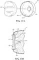
- FIG. 21is a bottom perspective view of the glenoid base component.
- FIG. 22is an illustration of the glenoid base component positioned in a pocket formed in the glenoid cavity and ready to receive a secondary glenoid component.
- FIG. 22Ais a perspective view of another glenoid base component and another secondary glenoid component.
- FIG. 22Bis a cross-sectional view of the glenoid base component and the secondary glenoid component of FIG. 22A installed in the glenoid cavity.
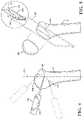
- FIG. 23is a perspective view of an alternative surgical tool for grasping implant components.
- FIG. 24is a partial cross-sectional view of the surgical tool of FIG. 23 .
- a robotic system 10for performing surgery on a patient.
- the version shown in FIG. 1comprises a material removal system for removing material from a workpiece (e.g., bone), but it should be appreciated that other types of robotic systems are also contemplated.
- the robotic system 10is shown in a surgical setting such as an operating room of a medical facility.
- the robotic system 10includes a machining station 12 and a guidance station 20 .
- the guidance station 20is set up to track movement of various objects in the operating room. Such objects include, for example, a surgical tool 22 , a humerus H of a patient, and a scapula S of the patient.
- the guidance station 20tracks these objects for purposes of displaying their relative positions and orientations to the surgeon and, in some cases, for purposes of controlling movement (e.g., causing movement, guiding movement, constraining movement, etc.) of the surgical tool 22 relative to virtual cutting boundaries or other virtual objects associated with the humerus H and scapula S.
- the guidance station 20includes a computer cart assembly 24 that houses a navigation controller 26 .
- a navigation interfaceis in operative communication with the navigation controller 26 .
- the navigation interfaceincludes a first display 28 adapted to be situated outside of a sterile field and a second display 29 adapted to be situated inside the sterile field.
- the displays 28 , 29are adjustably mounted to the computer cart assembly 24 .
- First and second input devicessuch as a keyboard and mouse can be used to input information into the navigation controller 26 or otherwise select/control certain aspects of the navigation controller 26 .
- Other input devicesare contemplated including a touch screen 30 or voice-activation.
- a localizer 34communicates with the navigation controller 26 .
- the localizer 34is an optical localizer and includes a camera unit 36 .
- Other types of localizersare also contemplated, including localizers that employ ultrasound, radio frequency (RF) signals, electromagnetic fields, and the like.
- the camera unit 36has an outer casing 38 that houses one or more optical position sensors 40 .
- at least two optical sensors 40are employed, preferably three or four.
- the optical sensors 40may be four separate charge-coupled devices (CCD). In one embodiment four, one-dimensional CCDs are employed. It should be appreciated that in other embodiments, separate camera units, each with a separate CCD, or two or more CCDs, could also be arranged around the operating room.
- the CCDsdetect infrared (IR) signals.
- the camera unit 36is mounted on an adjustable arm to position the optical sensors 40 with a field of view of the below discussed trackers that, ideally, is free from obstructions.
- the camera unit 36is adjustable in at least one degree of freedom by rotating about a rotational joint. In other embodiments, the camera unit 36 is adjustable about two or more degrees of freedom.
- the camera unit 36includes a camera controller 42 in communication with the optical sensors 40 to receive signals from the optical sensors 40 .
- the camera controller 42communicates with the navigation controller 26 through either a wired or wireless connection (not shown).
- One such connectionmay be an IEEE 1394 interface, which is a serial bus interface standard for high-speed communications and isochronous real-time data transfer. The connection could also use a company specific protocol.
- the optical sensors 40communicate directly with the navigation controller 26 .
- Position and orientation signals and/or dataare transmitted to the navigation controller 26 for purposes of tracking objects.
- the computer cart assembly 24 , display 28 , and camera unit 36may be like those described in U.S. Pat. No. 7,725,162 to Malackowski, et al. issued on May 25, 2010, entitled “Surgery System,” hereby incorporated by reference.
- the navigation controller 26can be a personal computer or laptop computer.
- the navigation controller 26has the display 28 , central processing unit (CPU) and/or other processors, memory (not shown), and storage (not shown).
- the navigation controller 26is loaded with software.
- the softwareconverts the signals received from the camera unit 36 into data representative of the position and orientation of the objects being tracked.
- the guidance station 20is operable with a plurality of tracking devices 44 , 46 , 48 , also referred to herein as trackers.
- one tracker 44is firmly affixed to the humerus H of the patient and another tracker 46 is firmly affixed to the scapula S of the patient.
- the trackers 44 , 46are firmly affixed to sections of bone.
- the trackers 44 , 46could be mounted like those shown in U.S. Patent Application Publication No. 2014/0200621, published on Jul. 17, 2014, entitled, “Navigation Systems and Methods for Indicating and Reducing Line-of-Sight Errors,” the entire disclosure of which is hereby incorporated by reference.
- the trackers 44 , 46could be mounted to other tissue types or parts of the anatomy.
- Various types of trackerscould be employed, including rigid trackers or flexible trackers like those shown in U.S. Pat. No. 8,457,719 to Moctezuma de la Barrera et al., entitled “Flexible Tracking Article and Method of Using the Same,” filed on Dec. 8, 2010, which is hereby incorporated by reference.
- the SpineMask® Non-Invasive Trackersold by Stryker Navigation (an operating division of Stryker Corporation), 4100 East Milham Ave., Kalamazoo, Mich., could be employed.
- a tool tracker 48is firmly attached to the surgical tool 22 .
- the tool tracker 48may be integrated into the surgical tool 22 during manufacture or may be separately mounted to the surgical tool 22 in preparation for surgical procedures.
- the surgical tool 22is attached to a manipulator 56 of the machining station 12 .
- Such an arrangementis shown in U.S. Pat. No. 9,119,655, issued Sep. 1, 2015, entitled, “Surgical Manipulator Capable of Controlling a Surgical Instrument in Multiple Modes,” the entire disclosure of which is hereby incorporated by reference.
- a separate trackermay be attached to a base 57 of the manipulator 56 to track movement of the base 57 in some embodiments.
- the working end of the surgical tool 22may be tracked via the base tracker by virtue of additional encoder data being provided by encoders in joints of the manipulator 56 , which provide joint position data that can be collectively processed to generate information regarding a location of the working end of the surgical tool 22 relative to the base 57 .
- the working end of the surgical tool 22which is being tracked by virtue of the tool tracker 48 (or base tracker in some cases), may be an energy applicator EA such as a rotating bur, saw blade, electrical ablation device, or the like.
- the energy applicator EAmay be a separate component that is releasably connected to a handpiece of the surgical tool 22 or may be integrally formed with the handpiece.
- the trackers 44 , 46 , 48can be battery powered with an internal battery or may have leads to receive power through the navigation controller 26 , which, like the camera unit 36 , receives external power.
- the optical sensors 40 of the localizer 34receive light signals from the trackers 44 , 46 , 48 .
- the trackers 44 , 46 , 48are active trackers.
- each tracker 44 , 46 , 48has at least three active tracking elements or markers for transmitting light signals to the optical sensors 40 .
- the active markerscan be, for example, light emitting diodes or LEDs 50 (see FIG. 2 ) transmitting light, such as infrared light.
- the optical sensors 40preferably have sampling rates of 100 Hz or more, more preferably 300 Hz or more, and most preferably 500 Hz or more. In some embodiments, the optical sensors 40 have sampling rates of 8000 Hz. The sampling rate is the rate at which the optical sensors 40 receive light signals from sequentially fired LEDs (not shown). In some embodiments, the light signals from the LEDs 50 are fired at different rates for each tracker 44 , 46 , 48 .
- Each of the LEDs 50are connected to a tracker controller (not shown) located in a housing of the associated tracker 44 , 46 , 48 that transmits/receives data to/from the navigation controller 26 .
- the tracker controllerstransmit data on the order of several Megabytes/second through wired connections with the navigation controller 26 .
- a wireless connectionmay be used.
- the navigation controller 26has a transceiver (not shown) to receive the data from the tracker controller.
- the trackers 44 , 46 , 48may have passive markers (not shown), such as reflectors that reflect light emitted from the camera unit 36 . The reflected light is then received by the optical sensors 40 . Active and passive arrangements are well known in the art.
- the trackers 44 , 46 , 48also include a gyroscope sensor and accelerometer, such as the trackers shown in U.S. Pat. No. 9,008,757, issued on Apr. 14, 2015, entitled, “Navigation System Including Optical and Non-Optical Sensors,” the entire disclosure of which is hereby incorporated by reference.
- the navigation controller 26includes a navigation processor 52 . It should be understood that the navigation processor 52 could include one or more processors to control operation of the navigation controller 26 .
- the processorscan be any type of microprocessor or multi-processor system.
- the navigation controller 26may additionally or alternatively comprise one or more microcontrollers, field programmable gate arrays, systems on a chip, discrete circuitry, and/or other suitable hardware, software, or firmware that is capable of carrying out the functions described herein.
- the term processoris not intended to limit the scope of any embodiment to a single processor.
- the camera unit 36receives optical signals from the LEDs 50 of the trackers 44 , 46 , 48 and outputs to the processor 52 signals relating to the position of the LEDs 50 of the trackers 44 , 46 , 48 relative to the localizer 34 . Based on the received optical (and non-optical signals in some embodiments), navigation processor 52 generates data indicating the relative positions and orientations of the trackers 44 , 46 , 48 relative to the localizer 34 using triangulation and/or other techniques.
- the navigation processor 52Prior to the start of the surgical procedure, additional data are loaded into the navigation processor 52 . Based on the position and orientation of the trackers 44 , 46 , 48 and the previously loaded data, the navigation processor 52 determines the position of the working end of the surgical tool 22 (e.g., the centroid of a surgical bur, cutting envelope of a sagittal saw, etc.) and the orientation of the surgical tool 22 relative to the tissue against which the working end is to be applied. In some embodiments, the navigation processor 52 forwards these data to a manipulator controller 54 . The manipulator controller 54 can then use the data to control the manipulator 56 as described in U.S. Pat. No. 9,119,655, issued Sep. 1, 2015, entitled, “Surgical Manipulator Capable of Controlling a Surgical Instrument in Multiple Modes,” the entire disclosure of which is hereby incorporated by reference.
- the surgical tool 22is controlled to stay within one or more preoperatively defined virtual boundaries set by the surgeon, which defines the material (e.g., tissue) of the humerus H and scapula S to be removed by the surgical tool 22 .
- These boundariesare defined by virtual objects stored in memory in the robotic system 10 (e.g., in the navigation controller 26 and/or the manipulator controller 54 ).
- the boundariesmay be defined within a virtual model of the humerus H and scapula S and be represented as a mesh surface, constructive solid geometry (CSG), voxels, or may be represented using other boundary representation techniques.
- the boundariesmay also be defined separately from virtual models of the humerus H and scapula S.
- the navigation processor 52also generates image signals that indicate the relative position of the working end of the surgical tool 22 to the tissue to be removed. These image signals are applied to the displays 28 , 29 .
- the displays 28 , 29based on these signals, generate images that allow the surgeon and staff to view the relative position of the working end to the surgical site.
- the displays, 28 , 29may include a touch screen or other input/output device that allows entry of commands.
- the surgical tool 22forms part of an end effector of the manipulator 56 .
- the manipulator 56has a plurality of links 58 extending from the base 57 , and a plurality of active joints (not numbered) for moving the surgical tool 22 with respect to the base 57 .
- the links 58may form a serial robotic arm structure as shown, a parallel robotic arm structure (not shown), or other suitable structure.
- the manipulator 56has the ability to operate in one or more of: (1) a free mode in which a user grasps the end effector of the manipulator 56 in order to cause movement of the surgical tool 22 (e.g., directly, through force/torque sensor measurements that cause active driving of the manipulator 56 , passively, or otherwise); (2) a haptic mode in which the user grasps the end effector of the manipulator 56 to cause movement as in the free mode, but is restricted in movement by the virtual boundaries defined by the virtual objects stored in the robotic system 10 ; (3) a semi-autonomous mode in which the surgical tool 22 is moved by the manipulator 56 along a tool path (e.g., the active joints of the manipulator 56 are operated to move the surgical tool 22 without requiring force/torque on the end effector from the user); (4) a service mode in which the manipulator 56 performs preprogrammed automated movements to enable servicing; or (5) other modes to facilitate preparation of the manipulator 56 for use, e.g., for draping, etc.
- the usermanually manipulates (e.g., manually moves or manually causes the movement of) the manipulator 56 to manipulate the surgical tool 22 to perform the surgical procedure on the patient, such as drilling, cutting, reaming, implant installation, and the like.
- the guidance station 20tracks the location of the surgical tool 22 and/or the manipulator 56 and provides haptic feedback (e.g., force feedback) to the user to limit the user's ability to manually move (or manually cause movement of) the surgical tool 22 beyond one or more predefined virtual boundaries that are registered (mapped) to the patient's anatomy, which results in highly accurate and repeatable drilling, cutting, reaming, and/or implant placement.
- haptic feedbacke.g., force feedback
- the manipulator controller 54may have a central processing unit (CPU) and/or other manipulator processors, memory (not shown), and storage (not shown).
- the manipulator controller 54is loaded with software as described below.
- the manipulator processorscould include one or more processors to control operation of the manipulator 56 .
- the processorscan be any type of microprocessor, multi-processor, and/or multi-core processing system.
- the manipulator controller 54may additionally or alternatively comprise one or more microcontrollers, field programmable gate arrays, systems on a chip, discrete circuitry, and/or other suitable hardware, software, or firmware that is capable of carrying out the functions described herein.
- the term processoris not intended to limit any embodiment to a single processor.
- the manipulator controller 54determines the desired location to which the surgical tool 22 should be moved based on forces and torques applied by the user on the surgical tool 22 .
- the manipulator 56emulates the user's desired positioning by sensing the applied forces and torques and reacting in a way that gives the user the impression that the user is actually moving the surgical tool 22 even though active motors on the joints are performing the movement.
- the manipulator controller 54determines the extent to which each of the plurality of links 58 needs to be moved in order to reposition the surgical tool 22 from the current location to the desired location.
- the data regarding where the plurality of links 58 are to be positionedis forwarded to joint motor controllers (not shown) (e.g., one for controlling each motor) that control the active joints of the manipulator 56 to move the plurality of links 58 and thereby move the surgical tool 22 from the current location to the desired location.
- a user control pendant assembly 60may be used to interface with the manipulator controller 54 in the semi-autonomous mode and/or to switch between the free mode, haptic mode, semi-autonomous mode, service mode, and/or other modes.
- the user control pendant assembly 60includes a processor or pendant controller 62 .
- the pendant controller 62may have a central processing unit (CPU) and/or other pendant processors, memory (not shown), and storage (not shown).
- the pendant controller 62is in communication with the manipulator controller 54 .
- the pendant controller 62is also in communication with switches (not shown) associated with user controls such as buttons 64 , 68 , 70 .
- the pendant processorcould include one or more processors to transmit signals resulting from pressing of buttons 64 , 68 , 70 on the user control pendant assembly 60 to the manipulator controller 54 .
- the practitionerdepresses button 64 (and may be required to hold down button 64 to continue autonomous operation).
- a feed ratee.g., velocity
- pre-operative imaging and/or intra-operative imagingmay be employed to visualize the patient's anatomy that requires treatment—such as the patient's shoulder joint.
- the surgeonplans where to place a shoulder implant system 100 with respect to the images and/or with respect to one or more 3-D models created from the images, such as 3-D models of the humerus H and the scapula S created from CT scan data, MRI data, or the like.
- 3-D models created from the imagessuch as 3-D models of the humerus H and the scapula S created from CT scan data, MRI data, or the like.
- Such modelsmay also be based on generic bone models morphed to resemble patient specific anatomy.
- Planningincludes determining a pose of each implant component of the shoulder implant system 100 with respect to the particular bone in which they are being placed, e.g., by identifying the desired pose of the implant component in the images and/or the appropriate 3-D model. This may include creating or positioning a separate 3-D model of the implant components with respect to the 3-D models of the patient's anatomy. Once the plan is set, then the plan is transferred to the robotic system 10 for execution.
- the 3-D modelsmay comprise mesh surfaces, constructive solid geometries (CSG), voxels, or may be represented using other 3-D modeling techniques.
- the robotic system 10may be employed to prepare the humerus H and a glenoid cavity G of a scapula S to receive the shoulder implant system 100 .
- the shoulder implant system 100comprises a humeral component 102 and a glenoid component 104 .
- the humerus His prepared by the robotic system 10 to receive the humeral component 102 , which in some embodiments is stemless and the glenoid cavity G is prepared by the robotic system 10 to receive the glenoid component 104 .
- Virtual boundaries, pre-defined tool paths, and/or other autonomous movement instructions, that correspond to the desired placement of the humeral component 102 and the glenoid component 104are created to control movement of the manipulator 56 so that the working end of the surgical tool 22 (e.g., bur, drill, saw) are controlled in a manner that ultimately places the components 102 , 104 according to the user's plan.
- Thismay comprise ensuring during the surgical procedure that the surgical tool 22 (or cutting accessory attached to it) stays within a pre-defined cutting volume delineating the bounds of the material to be removed to receive the implant.
- Thismay also comprise, for example, ensuring during the surgical procedure that a trajectory of the surgical tool 22 is aligned with a desired pose of peg holes, that the trajectory of the surgical tool 22 is aligned with a desired pose of pilot holes for anchoring screws, and the like. This may further comprise ensuring that a plane of the surgical tool 22 (e.g., for a sagittal saw) is aligned with a desired pose of a planar resection.
- the robotic system 10 and/or the usermay pre-operatively plan the desired cutting volume, trajectories, planar cuts, etc.
- the desired cutting volumesmay simply correspond to the geometry of the implants being used.
- these cutting volumesmay be virtually located and registered to the anatomy by virtue of the user planning the location of the implants relative to the 3-D models of the humerus H and scapula S and registering the 3-D models of the implants, along with the 3-D models of the humerus H and the scapula S to the actual humerus H and scapula S during the procedure.
- the robotic system 10 and/or the usermay also intra-operatively plan the desired cutting volume, trajectories, planar cuts, etc. or may intra-operatively adjust the cutting volumes, trajectories, planar cuts, etc. that were defined pre-operatively.
- the usercould position a drill or bur at a desired entry point relative to the anatomy of interest, e.g., the humerus, and orient the drill or bur until the display 28 , 29 shows that the trajectory of a rotational axis of the drill or bur is in a desired orientation. Once the user is satisfied with the trajectory, the user provides input to the robotic system 10 to set this trajectory as the desired trajectory to be maintained during the procedure.
- the inputcould be provided via input devices such as the mouse, keyboard, touchscreen, push button, foot pedal, etc. coupled to the navigation controller 26 or the manipulator controller 54 .
- input devicessuch as the mouse, keyboard, touchscreen, push button, foot pedal, etc. coupled to the navigation controller 26 or the manipulator controller 54 .
- This same procedurecan be followed for the user to set a desired planar cut, etc.
- 3-D models of the cutting volumes, desired trajectory, desired planar cuts, etc.are stored in memory for retrieval during the procedure.
- One or more boundaries used by the robotic system 10could be defined by a navigation pointer 106 by touching anatomy of interest with the navigation pointer 106 and capturing associated points on the anatomy with the guidance station 20 .
- the navigation pointer 106FIGS. 1 and 4
- the navigation pointer 106could be used to outline the boundary.
- the navigation pointer 106could be used to delineate soft tissue or other sensitive anatomical structures to be avoided by the surgical tool 22 . These points, for example, could be loaded into the robotic system 10 to adjust the tool path to be followed in the semi-autonomous mode so that the surgical tool 22 avoids these areas.
- Other methodscould be used to delineate and/or define anatomy of interest, e.g., as being anatomy to be removed, anatomy to be avoided, etc.
- a line haptic object LHmay be created and stored in the robotic system 10 to constrain movement of the surgical tool 22 to stay along the desired trajectory.
- the line haptic object LHmay have a starting point SP, as described further below and a target point TP, which defines a desired depth of the drill.
- a planar haptic object PH(see FIG. 5 ) may be created for constraining movement of the surgical tool 22 to stay along a desired plane.
- Other haptic object shapes, sizes, etc.are also contemplated, including those that define volumes of material to be removed to receive the components 102 , 104 , as described further below.
- the humerus His shown.
- the description that followsrelates to preparation of the humerus H to receive the humeral component 102 , but it should be appreciated that, during a surgical procedure, either of the humerus H or the glenoid cavity G may be prepared first to receive its associated implant component, or some combination of alternating preparation could be employed.
- the humerus His prepared by first defining a resection plane along which a humeral head HH is to be resected from a remaining portion of the humerus H.
- This resectionis planar in some embodiments, but may comprise a more complex surface topology in other embodiments.
- the resectioncould provide a contoured surface, an undulating surface of ridges, or the like.
- One of several optionsmay be employed to determine the location of the resection of the humeral head HH, and by extension the location of the planar haptic object PH.
- a surgeonmay prefer to make the resection along an anatomical neck AN.
- the surgeonmay establish a virtual resection plane for the resection by using the navigation pointer 106 , which comprises its own tracker 108 for purposes of determining a location of its tip 110 .
- Navigation pointers 106are used in registering pre-operative images or models to actual anatomy being treated during a surgical procedure.
- the navigation pointer 106may be used to register a pre-operative 3-D model (e.g., one generated from CT scan data, Mill data, or the like) of the humerus H to the actual humerus H and also to define the resection of the humeral head HH.
- a pre-operative 3-D modele.g., one generated from CT scan data, Mill data, or the like
- the usertouches the tip 110 of the navigation pointer 106 to at least three locations along the anatomical neck AN, and the navigation controller 26 determines positions of these plurality of landmarks in a coordinate system registered to the humerus H (one or more coordinate systems may be employed).
- the virtual resection planecan be defined as passing through each of the three points in the coordinate system.
- the location of the virtual resection planedefines a location of the planar haptic object PH shown in FIG. 5 .
- Other methods of establishing the resectionincludes placing the resection plane at a predetermined angle (e.g., 135 degrees or other angle) with respect to a longitudinal axis LA of the humerus (e.g. relative to an intramedullary axis of the intramedullary canal) defined in the coordinate system.
- a predetermined anglee.g. 135 degrees or other angle
- Yet another method of establishing the planecomprises selecting one or more landmarks on the humerus H, e.g., the greater tuberosity, lesser tuberosity, bicipital groove, and defining the resection based on the one or more landmarks, either alone, or in conjunction with the intramedullary axis of the intramedullary canal and/or in conjunction with an extramedullary axis or axis based on an outer shape of the humerus H.
- one or more landmarks on the humerus He.g., the greater tuberosity, lesser tuberosity, bicipital groove
- the robotic system 10creates the virtual object required to guide operation of the manipulator 56 and the surgical tool 22 and stores the virtual object in memory.
- the surgical tool 22comprises a sagittal saw blade 112 .
- the virtual objectin this case the planar haptic object PH, is employed to constrain movement of the saw blade 112 so that the resection is made according to the surgeon's plan. This may include operating the manipulator 56 in the haptic mode and/or semi-autonomous mode to perform the resection. In the haptic mode, the user manually manipulates the surgical tool 22 while the manipulator 56 keeps the saw blade 112 confined within the planar haptic object PH via haptic feedback to the user.
- Visual feedbackcan additionally be provided on the displays 28 , 29 , which depict a representation of the saw blade 112 and a representation of the humerus H and updates in substantially real-time such representations so that the user and/or others can visualize movement of the saw blade 112 relative to the humerus H during resection.
- the useroperates the saw blade 112 to finish the resection and ready the humerus H for further preparation to receive the humeral component 102 .
- the humeral head HHis manually resected using a conventional sagittal saw outfitted with a separate navigation tracker so that the user can visualize a location of the saw blade 112 relative to the desired resection on the displays 28 , 29 while manually resecting the humeral head HH.
- the robotic system 10autonomously aligns the saw blade 112 with the desired resection plane.
- Such autonomous positioningmay be initiated by the user pulling a trigger (not shown) on the surgical tool 22 , or otherwise providing input to the robotic system 10 to start the autonomous movement.
- a reference point RP of the surgical tool 22is first brought to within a predefined distance of a starting point SP of the planar haptic object PH (such as within a predefined starting sphere as shown or starting box). Once the reference point RP is within the predefined distance of the starting point SP, then pulling the trigger (or alternatively pressing a foot pedal or actuating some other input) causes the manipulator 56 to autonomously align and position the saw blade 112 on the desired plane.
- the robotic system 10may effectively hold the surgical tool 22 on the desired plane (i.e., within the planar haptic object PH) by tracking movement of the patient and autonomously adjusting the manipulator 56 as needed to keep the saw blade 112 on the desired trajectory/plane.
- the usermay then manually manipulate the surgical tool 22 to move (or cause movement of) the saw blade 112 within the planar haptic object PH toward the bone to resect the humeral head HH.
- the robotic system 10constrains the user's movement of the surgical tool 22 to stay in the planar haptic object PH by providing haptic feedback to the user should the user attempt to move the surgical tool 22 in a manner that deviates from the planar haptic object PH and the desired plane.
- the userdesires to return the manipulator 56 to a free mode, for unconstrained movement of the surgical tool 22 , the user can then pull the surgical tool 22 back along the planar haptic object PH, away from the patient, until an exit point of the planar haptic object PH is reached.
- the humeral component 102comprises a proximal body 114 having a semi-spherical head 116 and a taper 118 extending downwardly from the head 116 .
- the head 116is shaped to provide an articulating surface shaped to engage a corresponding articulating surface of the glenoid component 104 described further below.
- the proximal body 114may be formed of metal, such as any suitable metal implant material, plastic material, combinations thereof, and the like.
- the humeral component 102further comprises a distal body 120 .
- the distal body 120comprises a base flange 122 , a midsection 124 depending distally from the base flange 122 , and a pair of locking members 126 .
- a taper pocket 128is defined in the base flange 122 and terminates in the midsection 124 .
- the taper pocket 128is sized and shaped to receive the taper 118 . In the embodiment shown, the taper pocket 128 is centrally located in the distal body 120 , but could be eccentrically located in other embodiments.
- the taper pocket 128may be threaded or may otherwise have coupling features to engage the taper 118 (e.g., Morse taper, threads, etc.) and secure the proximal body 114 to the distal body 120 .
- the distal body 120may be formed of metal, such as any suitable metal implant material, plastic material, combinations thereof, and the like.
- the base flange 122includes a proximal end surface 123 , a distal bone-engaging surface 125 , and a side flange surface 127 .
- Proximal end surface 123may be flat as shown, but in other embodiments it may be inclined or sloped.
- Side flange surface 127may have a uniform height, the height measured from distal to proximal ends of side flange surface 127 , or the height may vary along proximal end surface 123 .
- Distal bone-engaging surface 125may include a porous surface, for example porous titanium alloy, across all or a portion of its surface to provide better fixation of the implanted base flange 122 with bone.
- midsection 124is coupled to the base flange 122 at a first end and extends distally from the base flange 122 along the implant axis IA to a second end.
- midsection 124has a straight portion, which may be cylindrical, but may further comprise a conical portion (not shown) distal to the straight portion, which may be conical or frustoconical.
- the taper pocket 128may extend distally along implant axis IA from proximal end surface 123 of base flange 122 .
- the taper pocket 128may extend only partially into the distal body 120 along the implant axis IA or it may extend entirely through the distal body 120 and define a taper throughbore.
- the taper 118 of the proximal body 114may be placed within the taper pocket 128 and attached thereto.
- the proximal body 114(e.g., humeral head component) may be attached by any known securement methods including screw or friction fit.
- the distal body 120may include additional holes for use with insertion/extraction tools and/or for accepting sutures.
- the locking members 126extend radially outwardly from the midsection 124 . It should be appreciated that one or more locking members 126 may be utilized.
- the locking members 126are sized and shaped to lock the distal body 120 to the humerus H by rotating into position in undercut portions of the humerus H. Referring to FIGS. 7 through 9 , the undercut is formed when first and second cavities 130 , 132 are created in the humerus H using the surgical tool 22 .
- the first cavity 130is sized and shaped to receive the locking members 126 and the midsection 124 when they are axially placed in the humerus H.
- the second cavity 132is sized and shaped to receive the locking members 126 when the locking members 126 rotate into a locked position.
- One or more volumetric virtual objects V 1 , V 2(see FIG. 9A ) define a volume of material to be removed from the humerus H to form the first cavity 130 and to form the second cavity 132 sized to receive the locking members 126 .
- the second cavity 132defines the undercut in the bone whereby the locking members 126 are movable from an unlocked position in the first cavity 130 to the locked position in the second cavity 132 to limit withdrawal of the distal body 120 from the humerus H.
- the manipulator controller 54is configured to operate the manipulator 56 to control movement of a drill, bur, saw blade, or other cutting tool, based on the one or more virtual objects V 1 , V 2 to form the second cavity 132 about the implant axis IA so that the locking members 126 are rotatable about the implant axis IA from the unlocked position to the locked position.
- the one or more virtual objects V 1 , V 2are sized and shaped so that the locking members 126 are rotatable at least 10 degrees, at least 30 degrees, at least 90 degrees, or more, about the implant axis IA to move to the locked position.
- the one or more virtual objects V 1 , V 2are sized so that a distal portion of the volume of material to be removed from the humerus H extends below the anatomical neck AN of the humerus and terminates above a diaphysis DPH of the humerus H (see FIG. 7 ) so that a substantial portion of a humeral canal remains intact after the distal body 120 is fully seated in the humerus H.
- the one or more virtual objects V 1 , V 2are registered to the coordinate system to which the pre-operative model is registered (or are defined in the pre-operative model) to define one or more virtual cutting boundaries for the surgical tool 22 so that the user is limited from removing more material than needed to accurately position the distal body 120 securely within the humerus H.
- the manipulator 56may be operated in the haptic mode during cutting to generate haptic feedback to the user based on a position of the surgical tool 22 relative to the virtual cutting boundaries.
- the manipulator 56may be controlled by the manipulator controller 54 to generate haptic feedback in response to the working end of the surgical tool 22 reaching or exceeding a virtual cutting boundary defined by the virtual objects V 1 , V 2 .
- the virtual object V 2is defined so that the second cavity 132 is formed semi-cylindrical in shape so that as the locking members 126 are rotated in the second cavity 132 bone remains to act as a stop 133 to limit rotation of the locking members 126 .
- Other shapes of the second cavity 132are also possible.
- the second cavity 132may comprise a pilot hole that defines a pathway for an anchor (e.g., a screw) to be placed to secure the distal body 120 to the humerus H.
- a series of stepsare shown to illustrate formation of the first cavity 130 and the second cavity 132 based on the virtual objects V 1 , V 2 , which can be haptic objects as described above.
- the surgical tool 22employs, for example, a bur 142 to remove material from the humerus H to form the first cavity 130 .
- the bur 142may be used in the free mode (using visualization of the desired boundary of the first cavity 130 as a guide), in the haptic mode (using haptic feedback to keep the surgical tool 22 within the virtual cutting boundary associated with the first cavity 130 ), or in the semi-autonomous mode in which the manipulator 56 moves the surgical tool 22 autonomously to form the first cavity 130 .
- the location of the working end of the surgical tool 22 relative to the humerus Hcan be visualized on the displays 28 , 29 , along with a visualization of the virtual objects V 1 , V 2 .
- a visualization of the virtual objects V 1 , V 2For instance, isometric, side, top, cross-sectional, or other views of the humerus H may be displayed with graphical representations of the virtual objects V 1 , V 2 overlaid on the representation of the humerus H.
- a representation of the working end of the surgical tool 22can be displayed in relation thereto and updated so that the user is able to visualize, in substantially real-time, a pose of the surgical tool 22 relative to the humerus H and the associated virtual cutting boundaries.
- the bur 142is replaced by a rotating blade 144 that extends radially outwardly from a rotating shaft and can be placed into the first cavity 130 and then moved laterally from the first cavity 130 to form the second cavity 132 as shown in a third step S 3 .
- the blade 144may be used in the free mode (using visualization of the desired boundary as a guide), in the haptic mode (using haptic feedback to keep the surgical tool 22 within the virtual cutting boundary), or in the semi-autonomous mode in which the manipulator 56 moves the surgical tool 22 autonomously to form the second cavity 132 .
- the humerus His ready to receive the distal body 120 in a fourth step S 4 .
- the distal body 120is inserted in the first cavity 130 until it bottoms out in the humerus H.
- a fifth step S 5the distal body 120 is rotated so that the locking members 126 rotate into the undercut portions formed by the second cavity 132 .
- the distal body 120is secure in the humerus H.
- Additional fixation methodsmay be employed, such as screws, bone cement, and the like to further hold the distal body 120 in the cavities 130 , 132 .
- bone cementmay be injected into one or both of the cavities 130 , 132 prior to inserting the distal body 120 .
- the second cavity 132may be shaped so that the bone forms rotation limiting features to limit rotation.
- rotation limiterssuch as ramps 131 may be provided along which the locking members 126 ride when being rotated into the undercut portions. See, for example, the ramps 131 shown in FIG. 10A (only one shown, but one for each locking member 126 may be present).
- the locking members 126may be flexible to act like detents so that the locking members 126 flex when being rotated through the ramps 131 , the locking members 126 may be spring-loaded to flex, or the locking members 126 may be connected in various ways to the midsection 124 to fit over the ramps 131 while maintaining a stable fit once in their final position.
- the locking members 126may be in the shape shown in FIG. 6 or may comprise other shapes, such as locking pin shapes, ball-shapes, and the like.
- a sixth step S 6the proximal body 114 is brought into engagement with the distal body 120 and fixed to the distal body 120 to limit relative movement.
- the humeral component 102is thus ready for engaging the glenoid component 104 .
- Distal body 150(also referred to as a base) is shown.
- Distal body 150includes base flange 152 coupled with a central anchor 154 .
- the base flange 152may have a generally rounded cruciform shape, although in other examples, the base flange 152 may have other shapes including oblong or annular.
- the base flange 152includes a proximal end surface 156 , a distal bone-engaging surface 157 , and a side base flange surface 160 .
- Proximal end surface 156may be flat as shown, but in other embodiments it may be inclined or sloped.
- Side base flange surface 160may have a uniform height, the height measured from distal to proximal ends of side base flange surface 160 , or the height may vary along proximal end surface 156 .
- Distal bone-engaging surface 157may include a porous surface, for example porous titanium alloy, across all or a portion of its surface to provide better fixation of the implanted distal body 150 with the bone.
- Base flange 152includes at least one hole 162 extending from proximal end surface 156 to distal bone-engaging surface 157 .
- the holes 162are each adapted to receive a screw.
- the screwsmay be variable angle locking screws capable of being inserted through holes 162 at variable angles, with the heads of the screws having locking threads to mate with corresponding locking threads in the holes.
- the screwsmay engage the bone to provide fixation of the distal body 120 in the bone.
- the screwsmay have varying lengths to accommodate bone purchase to help with fixation, although any combination of screw lengths may be appropriate.
- the medial screwhas a length that is greater than the length of central anchor 154 .
- the distal body 150includes central anchor 154 coupled to the base flange 152 at a first end and extending distally from the base flange 152 along the implant axis IA to a second end.
- the central anchor 154has a straight portion 164 , which may be cylindrical, and a tapered portion 166 , which may be conical or frustoconical. Tapered portion 166 is tapered along the implant axis IA so that the proximal end of the tapered portion 166 has a relatively large diameter, with the diameter of the central anchor 154 generally narrowing toward second end until the central anchor terminates in distal tip 168 .
- the distal body 150may further define an opening 170 .
- Opening 170may extend distally along the implant axis IA from proximal end surface 156 of base flange 152 .
- Opening 170may extend partially or fully through the central anchor 154 along the implant axis IA or it may be shallow and extend only into base flange 152 .
- the proximal body 114may be placed within opening 170 and attached thereto, for example by a taper lock such as a Morse taper.
- the proximal body 114may be attached by any known securement means including screw or friction fit.
- the distal body 150may include additional holes for use with insertion/extraction tools and/or for accepting sutures.
- FIG. 13shows the distal body 150 implanted within the humerus H with variable angle locking screws.
- the benefit of using screws of different lengthsis particularly well illustrated in FIG. 13 .
- a screw that engages a hole 162 on the medial side of base flange 152may be longer than the other screws, as there may be a greater depth of bone available in this area.
- the first virtual object V 1may be sized and shaped to correspond to the central anchor 154 to define the volume of material to be removed from the humerus H to receive the central anchor 154 .
- One or more secondary virtual objects V 2may be sized and shaped to correspond to pilot holes to be placed in the humerus H for the one or more variable angle locking screws.
- the secondary virtual objectsmay comprise trajectories, such as line haptic objects LH.
- the locking screwscomprise locking members that are used to resist withdrawal of the distal body 150 from the humerus H.
- the robotic system 10autonomously aligns the rotational axis R of the surgical tool 22 with the desired trajectory. Such autonomous positioning may be initiated by the user pulling a trigger on the surgical tool 22 , or otherwise providing input to the robotic system 10 to start the movement.
- a tool center point (TCP) of the surgical tool 22is first brought to within a predefined distance of a starting point SP of the line haptic object LH that provides the desired trajectory (such as within a predefined starting sphere as shown).
- the robotic system 10may effectively hold the surgical tool 22 on the desired trajectory by tracking movement of the patient and autonomously adjusting the manipulator 56 as needed to keep the surgical tool 22 on the desired trajectory.
- the robotic system 10While the robotic system 10 holds the surgical tool 22 on the desired trajectory, the user may then manually manipulate the surgical tool 22 to move (or cause movement of) the drill or bur along the line haptic object LH toward the bone to form the pilot holes for the screws.
- the robotic system 10constrains the user's movement of the surgical tool 22 to stay along the desired trajectory by providing haptic feedback to the user should the user attempt to move the surgical tool 22 in a manner that deviates from the line haptic object LH and the desired trajectory.
- the userdesires to return the manipulator 56 to a free mode, for unconstrained movement of the surgical tool 22 , the user can then pull the surgical tool 22 back along the line haptic object LH, away from the patient, until an exit point of the line haptic object LH is reached.
- the virtual objects (e.g., haptic objects) used to constrain the user's movement along the desired trajectorymay also indicate, such as via haptic feedback, when the user has reach the desired depth of the pilot holes, e.g., reached the target point TP. Separate virtual boundaries could also be used to set the desired depths.
- the robotic system 10may autonomously drill the pilot holes to the desired depths. In further cases, the robotic system 10 may initially drill autonomously, but then final drilling may be done manually, or vice versa. Once the pilot holes are created, the screws can then be placed manually or with a driver of the surgical tool 22 . In some embodiments, pilot holes 102 may be unnecessary and the screws can be placed over guide wires placed by the robotic system 10 or without any guidance.
- a pocket 174may be formed in the humerus H by the surgical tool 22 , i.e., an additional volume of material may be removed from the humerus H (e.g., with the bur 142 ), so that the base flange 152 is seated below the resection (in some cases only a portion of the base flange 152 is seated below the resection).
- the pocket 174may be defined by a separate virtual boundary for purposes of controlling the manipulator 56 when forming the pocket 174 and may be shaped to receive the base flange 152 in a mating relationship.
- the base flange 152has a geometry that rotational locks the distal body 150 to the humerus H when inserted into the pocket 174 (see FIG. 13C ).
- the distal body of the humeral component 102could have ribs, waffle-patterns, ridges, cross-hatches, other non-circular shapes, and the like, that mate with corresponding features formed in the humerus H by the surgical tool 22 for further securing the distal body to the humerus H.
- these featurescan be incorporated into the humerus H and the distal body to avoid the need for cement or other adhesives or fastening mechanisms.
- cements, other adhesives, and/or fastening mechanismscan be used in addition to these features.
- a locking channel 176could be formed in the humerus H by the surgical tool 22 to receive distal body 178 .
- the distal body 178has a locking flange 180 formed along a distal end.
- the locking channel 176 and the locking flange 180are arcuate in shape so that the locking flange 180 slides into the locking channel 176 along a curvilinear path.
- the locking channel 176 and locking flange 180are straight.
- the locking channel 176may be formed with one open end or two open ends (as shown).
- the locking channel 176may be formed in any orientation with respect to the humerus H, there could be multiple locking channels 176 , and/or the locking channel 176 may be generally centrally located or may be offset to one side. Other variations of locking channels are also contemplated.
- a humeral head component 184like that shown in FIG.
- the distal body 178could be used, which integrates the proximal body 114 and distal body 178 into a unitary component.
- the distal body 178comprises a reverse shoulder implant component for attaching to the humerus H.
- a hemi-spherical head component(similar to that shown in FIG. 13F ) is installed in the glenoid cavity G to interface with an articular surface of the distal body 178 .
- the implant components showncould comprise one part or multiple parts, e.g., in modular implant systems.
- the distal body 178 shown in FIG. 13Fcould comprise a base and an insert like that shown in FIGS. 22A and 22B below and/or could comprise additional fasteners, such as screws to lock the implant component to bone. Similar shapes and implant styles as those shown in FIGS. 13D-13H could also be employed for the glenoid cavity G and the glenoid component.
- Drill, bur, or saw speedcan be controlled by the user via the trigger or can be controlled automatically based on the particular location of the drill, bur, or saw relative to the patient's anatomy. For instance, a rotational speed of the drill may be set high during initial drilling into the bone, but may be slowed during further drilling into the bone, and set even slower during final drilling to the final depth.
- Preparation of the glenoid cavity Gmay comprise a combination of manual and robotic operations such as drilling, reaming, burring, and the like.
- glenoid preparationcan be done at any time in the procedure, and can be done immediately following humeral head HH resection, but before placement of the humeral component 102 , after placement of the humeral component 102 , or before preparation of the humerus H.
- a retractor 199is used to retract the humerus H and expose the glenoid cavity G.
- a center hole 200is first prepared through the glenoid cavity G.
- the center hole 200may be defined by a virtual object, such as a line haptic object LH that defines the trajectory and stopping location for the center hole 200 .
- the location of the center hole 200could be defined pre-operatively/intra-operatively during planning.
- the center hole 200could be located by virtue of capturing points on the scapula S with the navigation pointer 106 .
- the navigation pointer 106could be used to outline a periphery of the glenoid cavity G and/or interior points of the glenoid cavity G.
- the virtual object for the center hole 200(e.g., the trajectory) could then be automatically defined at a center/centroid of the outlined periphery and normal to the glenoid surface at that location.
- screw locations, reaming patterns, etc.could be defined based on the information determined by the points that are localized with the navigation pointer 106 .
- a bur, drill or other accessorymay be used in the surgical tool 22 to form the center hole 200 in the free mode (using visualization of the desired trajectory and depth as a guide), in the haptic mode (using haptic feedback to keep the surgical tool 22 on the trajectory and at a suitable depth), or in the semi-autonomous mode in which the manipulator 56 moves the surgical tool 22 autonomously along the trajectory to prepare the center hole 200 at the desired depth.
- the location of the working end of the surgical tool 22 relative to the glenoid cavity Gcan be visualized on the displays 28 , 29 , along with a visualization of the virtual object, such as the line haptic object LH.
- a visualization of the virtual objectsuch as the line haptic object LH.
- isometric, side, top, cross-sectional, or other views of a representation of the glenoid cavity Gmay be displayed with virtual representations of the line haptic object LH overlaid on the representation of the glenoid cavity G.
- a representation of the working end of the surgical tool 22can be displayed in relation thereto and updated so that the user is able to visualize, in substantially real-time, a pose of the surgical tool 22 relative to the glenoid cavity G and the associated virtual line haptic object LH, which also defines a virtual cutting boundary for the surgical tool 22 .
- an appropriately sized reamer head 202can be used on the surgical tool 22 to contour the glenoid cavity G to provide a desired contoured surface for receiving the glenoid component 104 .
- the reamer head 202has a distally protruding centering pin (not shown) that is seated in the center hole 200 to center the reamer head 202 and at least partially orient the reamer head 202 during reaming operations.
- Another virtual objectmay also be associated with the desired contoured surface of the glenoid cavity G so that the reamer head 202 is limited from penetrating beyond the desired contoured surface.
- the center hole 200may not be needed to locate the centering pin of the reamer head 202 as the manipulator 56 controls the location of the reamer head 202 based on the associated contoured surface virtual object.
- peg holes 204can be formed through the glenoid cavity G similar to the center hole 200 .
- Each of the peg holes 204may be defined by a virtual object, such as a line haptic object LH that defines the trajectory and stopping location for the peg hole 204 .
- a bur, drill or other accessorymay be used in the surgical tool 22 to form the peg holes 204 in the free mode (using visualization of the desired trajectory and depth as a guide), in the haptic mode (using haptic feedback to keep the surgical tool 22 on the trajectory and at a suitable depth), or in the semi-autonomous mode in which the manipulator 56 moves the surgical tool 22 autonomously along the trajectory to prepare the peg holes 204 at the desired depths.
- one or more of the virtual objectsmay be active at a given time, inactive, or combinations thereof.
- multiple, separate line haptic objects LH defining the desired trajectoriesare employed, but only one or more of them may be active at any given time so that the user and/or the manipulator 56 is able to focus on preparing one peg hole at a time.
- the manipulator 56is able to lock the surgical tool 22 on that line haptic object LH without inadvertently locking onto a different, adjacent line haptic object.
- the usercan also manually select, via the user interface for the navigation controller 26 , which peg hole is to be prepared and the robotic system 10 can activate the associated line haptic object LH accordingly.
- the glenoid component 104can be placed in the glenoid cavity G and secured by press-fit, bone cement or other adhesive, screws, or otherwise.
- the bur 142may be used to shape the glenoid cavity G into the desired shape. Furthermore, the bur 142 may be employed to shape the glenoid cavity G as shown in FIG. 20 or may be used to form alternative shapes in the glenoid cavity G. For example, the glenoid cavity G may be shaped in a manner that provides a rotational lock between the glenoid component and the scapula S.
- the glenoid componentmay comprise ribs, waffle-patterns, ridges, cross-hatches, other non-circular shapes, and the like, that mate with corresponding features formed in the glenoid cavity G by the bur 142 to secure the glenoid component to the scapula S.
- these featurescan be incorporated into the glenoid cavity G and the glenoid component to avoid the need for cement or other adhesives or fastening mechanisms.
- cements, other adhesives, and/or fastening mechanismscan be used in addition to these features.
- FIG. 20illustrates that a volume of material has been removed from the scapula S using the bur 142 .
- a pocket 210is formed in the scapula S for receiving glenoid base component 212 , shown in FIG. 21 .
- the glenoid base component 212comprises a base flange 214 that has a plurality of rotational locking features 216 designed to seat in the pocket 210 and prevent rotation of the glenoid base component 212 in the glenoid cavity G.
- the locking features 216are shown as arms of a cruciform design, but alternative forms of locking features 216 could be employed, e.g., the base flange 214 may be formed in any shape that has a locking feature for engaging the scapula S in a manner that limits rotation.
- the locking featuresmay comprise ribs, waffle-patterns, ridges, cross-hatches, other non-circular shapes, and the like, that mate with corresponding features formed in the glenoid cavity G.
- a central anchor 218depends distally from the base flange 214 to seat in a separate pocket 220 .
- the anchor 218may be offset from center to prevent rotation (such as when the base flange 214 is circular), multiple anchors may be present, or the like.
- Various forms of anchors, such as pegs, screws, and the likemay be employed.
- the base flange 214may comprise one or more separate openings to accommodate one or more screws to fix the base flange 214 to bone.
- the base flange 214may be formed of metal, such as any suitable metal implant material, plastic, combinations thereof, and the like.
- the glenoid base component 212may further comprise a plurality of snap-fit features, such as ribs 222 .
- the ribs 222are shown disposed at the outer ends of the arms of the cruciform design in a circumferentially spaced manner to receive a secondary glenoid component 224 shown in FIG. 22 .
- the ribsmay extend completely circumferentially about the base flange 214 .
- the secondary glenoid component 224may resemble the glenoid component 104 shown in FIG. 19 , but without the pegs, and is adapted to provide an articulation surface like the glenoid component 104 .
- the secondary glenoid component 224comprises one or more distally projecting detents 226 shaped and arranged to engage the ribs 222 in a snap-fit manner.
- the detents 226are shaped to snap-lock to the ribs 222 to inhibit removal of the secondary glenoid component 224 once snapped into place.
- glenoid base components and secondary glenoid componentsare possible.
- a predefined gap of desired depthis provided between the glenoid surface surrounding the base flange 214 and the ribs 222 , so that the detents 226 are able to engage the ribs 222 and suitably rest in the gap when snap-locked.
- another glenoid base component 232may be seated in pocket 230 formed by the bur 142 .
- the glenoid base component 232comprises a base 233 and a peripheral rim 234 extending proximally from the base 233 to define an insert cavity.
- the rim 234is flush with, slightly distally setback from, or slightly proud of the prepared and/or surrounding glenoid surface (see FIG. 22B ).
- a peg, taper, screw, or other type of anchor 235may depend distally from the base 233 and may be offset from a center of the base 233 to further rotationally lock the glenoid base component 232 to the scapula S and/or to limit axial withdrawal of the glenoid base component 232 from the scapula S.
- the base 233may have openings sized to receive screws to further fix the base 233 to bone.
- the anchor 235could also be cannulated to receive a screw therethrough for fixation.
- the glenoid base component 232could be further seated in the pocket 230 with a press-fit, cement or other adhesive, fasteners, or the like.
- Secondary glenoid component 236is inserted into the insert cavity within the periphery of the rim 234 .
- the secondary glenoid component 236may have an upper surface 237 that is flush with or slightly proud of the rim 234 .
- the secondary glenoid component 236may be formed of metal or plastic material, similar to the glenoid component 104 .
- the secondary glenoid component 236may be attached to the glenoid base component 232 with adhesive, by press-fit, snap-fit, taper lock, or by another fastening mechanism.
- the glenoid surface surrounding the glenoid base component 232is contoured by the bur 142 , reamer, or other tool. In other cases, the surrounding glenoid surface may be untouched, i.e., the only bone removed from the glenoid cavity G is to form the pocket 230 .
- FIGS. 23 and 24another surgical tool 240 is shown for use in grasping and manipulating implant components.
- the surgical tool 240forms part of an end effector that is attachable to the manipulator 56 such that the manipulator controller 54 is able to control positioning of the surgical tool 240 in the same manner previously described for positioning the surgical tool 22 .
- the robotic system 10via the surgical tool 240 , is able to precisely position the implant components, such as any of the implant components previously described.
- Such positioningmay include positioning the implant components through incisions in the patient to locate the implant components at desired locations, e.g., at desired locations on the patient's anatomy, within prepared pockets in bone, at desired locations with respect to other implant components, etc.
- the surgical tool 240comprises a coupler 242 configured for coupling to the manipulator 56 , such as by fasteners, clamps, or any other suitable coupling mechanism.
- a housing 244extends forward from the coupler 242 .
- a pair of fingers 246are movable relative to the housing 244 and each other to engage the implant component (represented generally at 248 ).
- the fingers 246are elongated in shape and have a slim profile to facilitate movement into and out of the incision in the patient. In some embodiments, the fingers 246 have a thickness of 5 millimeters or less, 3 millimeters or less, or 1 millimeter or less.
- the fingers 246comprise an extension portion 250 and a gripping portion 252 shaped to engage the implant component 248 .
- the gripping portions 252may curve toward one another as shown in FIG. 24 to engage the implant component 248 .
- Each of the gripping portions 252may also comprise a gripping pad 254 to facilitate a frictional grip on the implant component 248 .
- the gripping pad 254may merely be a roughed surface of the fingers 246 or may be a separate component.
- the fingers 246may be formed of metal, plastic, or combinations thereof.
- the gripping pad 254may be formed of metal, plastic, elastic material, or combinations thereof.
- the actuator assembly 258is operable to move the fingers 246 from their engaged position to a disengaged position to release the implant component 248 .
- the actuator assembly 258comprises an actuator 260 and a drive rod 262 configured to be moved by the actuator 260 .
- the drive rod 262has a distal end 265 shaped (e.g., ball-shaped) to engage cam portions 263 of the fingers 246 .
- the actuator 260may be a linear actuator and may be electric, pneumatic, hydraulic, or combinations thereof.
- the actuator 260may be controlled by the manipulator controller 54 or a separate controller.
- a button(not shown) or any other suitable input device may be in communication with the manipulator controller 54 or other controller to cause the controller to output a signal to the actuator 260 to move the drive rod 262 in a desired manner. Operation of the actuator 260 may also be automated in some cases.
- the distal end 265 of the drive rod 262engages the cam portions 263 and, upon further linear extension of the drive rod 262 , the distal end 265 urges the fingers 246 apart to their release positions. It should be appreciated that other configurations of the surgical tool 240 are possible.
- the fingers 246may comprise loops at their distal ends for grasping the implant component, additional fingers 246 may be employed, other types of actuators may be used to control movement of the fingers 246 such as separate actuators for each finger 246 , only one finger 246 may be movable relative to the housing 244 while the other remains stationary, and so on.
Landscapes
- Health & Medical Sciences (AREA)
- Engineering & Computer Science (AREA)
- Life Sciences & Earth Sciences (AREA)
- Surgery (AREA)
- Robotics (AREA)
- Animal Behavior & Ethology (AREA)
- Heart & Thoracic Surgery (AREA)
- Biomedical Technology (AREA)
- General Health & Medical Sciences (AREA)
- Public Health (AREA)
- Veterinary Medicine (AREA)
- Molecular Biology (AREA)
- Medical Informatics (AREA)
- Nuclear Medicine, Radiotherapy & Molecular Imaging (AREA)
- Orthopedic Medicine & Surgery (AREA)
- Transplantation (AREA)
- Oral & Maxillofacial Surgery (AREA)
- Cardiology (AREA)
- Vascular Medicine (AREA)
- Mechanical Engineering (AREA)
- Physical Education & Sports Medicine (AREA)
- Prostheses (AREA)
- Manipulator (AREA)
Abstract
Description
Claims (27)
Priority Applications (2)
| Application Number | Priority Date | Filing Date | Title |
|---|---|---|---|
| US16/181,750US11432945B2 (en) | 2017-11-07 | 2018-11-06 | Robotic system for shoulder arthroplasty using stemless implant components |
| US17/874,546US12370063B2 (en) | 2017-11-07 | 2022-07-27 | Robotic system for shoulder arthroplasty using stemless implant components |
Applications Claiming Priority (2)
| Application Number | Priority Date | Filing Date | Title |
|---|---|---|---|
| US201762582626P | 2017-11-07 | 2017-11-07 | |
| US16/181,750US11432945B2 (en) | 2017-11-07 | 2018-11-06 | Robotic system for shoulder arthroplasty using stemless implant components |
Related Child Applications (1)
| Application Number | Title | Priority Date | Filing Date |
|---|---|---|---|
| US17/874,546ContinuationUS12370063B2 (en) | 2017-11-07 | 2022-07-27 | Robotic system for shoulder arthroplasty using stemless implant components |
Publications (2)
| Publication Number | Publication Date |
|---|---|
| US20190133790A1 US20190133790A1 (en) | 2019-05-09 |
| US11432945B2true US11432945B2 (en) | 2022-09-06 |
Family
ID=64183931
Family Applications (2)
| Application Number | Title | Priority Date | Filing Date |
|---|---|---|---|
| US16/181,750Active2039-09-04US11432945B2 (en) | 2017-11-07 | 2018-11-06 | Robotic system for shoulder arthroplasty using stemless implant components |
| US17/874,546ActiveUS12370063B2 (en) | 2017-11-07 | 2022-07-27 | Robotic system for shoulder arthroplasty using stemless implant components |
Family Applications After (1)
| Application Number | Title | Priority Date | Filing Date |
|---|---|---|---|
| US17/874,546ActiveUS12370063B2 (en) | 2017-11-07 | 2022-07-27 | Robotic system for shoulder arthroplasty using stemless implant components |
Country Status (2)
| Country | Link |
|---|---|
| US (2) | US11432945B2 (en) |
| EP (2) | EP3479792B1 (en) |
Cited By (6)
| Publication number | Priority date | Publication date | Assignee | Title |
|---|---|---|---|---|
| US20230149093A1 (en)* | 2018-12-27 | 2023-05-18 | Mako Surgical Corp. | Systems and methods for surgical planning based on bone density |
| US11944392B2 (en) | 2016-07-15 | 2024-04-02 | Mako Surgical Corp. | Systems and methods for guiding a revision procedure |
| US20240138932A1 (en)* | 2022-10-28 | 2024-05-02 | Warsaw Orthopedic, Inc. | Systems and methods for controlling one or more surgical tools |
| WO2024137963A1 (en) | 2022-12-21 | 2024-06-27 | Mako Surgical Corp. | Surgical clamp assembly for fixing a navigation tracker to a portion of bone |
| WO2025019226A1 (en) | 2023-07-14 | 2025-01-23 | Mako Surgical Corp. | Surgical tracker assemblies with optimized size, weight, and accuracy |
| US12370061B2 (en) | 2019-08-29 | 2025-07-29 | Mako Surgical Corp. | Robotic surgery system for augmented arthroplasty procedures |
Families Citing this family (12)
| Publication number | Priority date | Publication date | Assignee | Title |
|---|---|---|---|---|
| WO2018076114A1 (en) | 2016-10-28 | 2018-05-03 | Orthosoft Inc. | Robotic cutting workflow |
| US10806529B2 (en)* | 2017-07-20 | 2020-10-20 | Mako Surgical Corp. | System and method for robotically assisting a surgical procedure |
| CN107551387B (en)* | 2017-08-17 | 2020-05-15 | 济南优科医疗技术有限公司 | Multifunctional auxiliary treatment robot |
| US11432945B2 (en) | 2017-11-07 | 2022-09-06 | Howmedica Osteonics Corp. | Robotic system for shoulder arthroplasty using stemless implant components |
| CN114449969B (en)* | 2019-09-30 | 2025-08-12 | 马科外科公司 | System and method for guiding movement of a tool |
| US11944396B2 (en)* | 2020-03-27 | 2024-04-02 | Mako Surgical Corp. | Systems and methods for controlling robotic movement of a tool based on a virtual boundary |
| AU2021202801A1 (en) | 2020-05-07 | 2021-11-25 | Howmedica Osteonics Corp. | Stemless metaphyseal humeral implant |
| EP3949889A1 (en) | 2020-08-05 | 2022-02-09 | MAKO Surgical Corp. | Robotic surgical system including a coupler for connecting a tool to a manipulator and methods of using the coupler |
| CN112603542B (en)* | 2020-12-07 | 2022-03-29 | 雅客智慧(北京)科技有限公司 | Hand-eye calibration method and device, electronic equipment and storage medium |
| US20240415587A1 (en)* | 2021-06-07 | 2024-12-19 | National Taiwan University | Puncture guiding system and method |
| WO2024187003A2 (en)* | 2023-03-07 | 2024-09-12 | Monogram Orthopaedics Inc. | Robotic surgery system layouts and related methods |
| CN117653265B (en)* | 2024-01-31 | 2024-04-26 | 鑫君特(苏州)医疗科技有限公司 | Tibia osteotomy planning device and tibia automatic osteotomy device for keel groove structure |
Citations (104)
| Publication number | Priority date | Publication date | Assignee | Title |
|---|---|---|---|---|
| US5824085A (en) | 1996-09-30 | 1998-10-20 | Integrated Surgical Systems, Inc. | System and method for cavity generation for surgical planning and initial placement of a bone prosthesis |
| US6002859A (en) | 1997-02-21 | 1999-12-14 | Carnegie Mellon University | Apparatus and method facilitating the implantation of artificial components in joints |
| USRE36974E (en) | 1993-05-14 | 2000-11-28 | Bonutti; Peter M. | Suture anchor |
| US6205411B1 (en) | 1997-02-21 | 2001-03-20 | Carnegie Mellon University | Computer-assisted surgery planner and intra-operative guidance system |
| US6500195B2 (en) | 1993-05-14 | 2002-12-31 | Peter M. Bonutti | Method and apparatus for anchoring a suture |
| US20030055502A1 (en) | 2001-05-25 | 2003-03-20 | Philipp Lang | Methods and compositions for articular resurfacing |
| US6702821B2 (en) | 2000-01-14 | 2004-03-09 | The Bonutti 2003 Trust A | Instrumentation for minimally invasive joint replacement and methods for using same |
| US6770078B2 (en) | 2000-01-14 | 2004-08-03 | Peter M. Bonutti | Movable knee implant and methods therefor |
| US20060089646A1 (en) | 2004-10-26 | 2006-04-27 | Bonutti Peter M | Devices and methods for stabilizing tissue and implants |
| US7104996B2 (en) | 2000-01-14 | 2006-09-12 | Marctec. Llc | Method of performing surgery |
| US20070066917A1 (en) | 2005-09-20 | 2007-03-22 | Hodorek Robert A | Method for simulating prosthetic implant selection and placement |
| US7206627B2 (en) | 2002-03-06 | 2007-04-17 | Z-Kat, Inc. | System and method for intra-operative haptic planning of a medical procedure |
| US20070179626A1 (en) | 2005-11-30 | 2007-08-02 | De La Barrera Jose L M | Functional joint arthroplasty method |
| US20080004633A1 (en) | 2006-05-19 | 2008-01-03 | Mako Surgical Corp. | System and method for verifying calibration of a surgical device |
| US20080058945A1 (en) | 2006-03-13 | 2008-03-06 | Mako Surgical Corp. | Prosthetic device and system and method for implanting prosthetic device |
| US7468075B2 (en) | 2001-05-25 | 2008-12-23 | Conformis, Inc. | Methods and compositions for articular repair |
| US20090000626A1 (en) | 2002-03-06 | 2009-01-01 | Mako Surgical Corp. | Haptic guidance system and method |
| US7510557B1 (en) | 2000-01-14 | 2009-03-31 | Bonutti Research Inc. | Cutting guide |
| WO2009057964A2 (en) | 2007-10-30 | 2009-05-07 | Curexo Inc. | Clamp for registration of bone position and surgical robot by using the same |
| US7534263B2 (en) | 2001-05-25 | 2009-05-19 | Conformis, Inc. | Surgical tools facilitating increased accuracy, speed and simplicity in performing joint arthroplasty |
| US20090157192A1 (en) | 2007-12-14 | 2009-06-18 | Microdexterity Systems, Inc. | Replacement joint |
| US7618451B2 (en) | 2001-05-25 | 2009-11-17 | Conformis, Inc. | Patient selectable joint arthroplasty devices and surgical tools facilitating increased accuracy, speed and simplicity in performing total and partial joint arthroplasty |
| US20090292364A1 (en)* | 2008-05-21 | 2009-11-26 | Linares Medical Devices, Llc | Shoulder implant with first and second composite sub-assemblies and improved mounting anchors for establishing a secure joint |
| US20100106194A1 (en) | 2004-10-26 | 2010-04-29 | P Tech, Llc | Stabilizing a spinal anatomical structure |
| US7708741B1 (en) | 2001-08-28 | 2010-05-04 | Marctec, Llc | Method of preparing bones for knee replacement surgery |
| US7725162B2 (en) | 2000-01-27 | 2010-05-25 | Howmedica Leibinger Inc. | Surgery system |
| WO2010068213A1 (en) | 2008-12-11 | 2010-06-17 | Mako Surgical Corp. | Implant planning using areas representing cartilage |
| WO2010068212A1 (en) | 2008-12-11 | 2010-06-17 | Mako Surgical Corp. | Implant planning for multiple implant components using constraints |
| US20100153081A1 (en) | 2008-12-11 | 2010-06-17 | Mako Surgical Corp. | Implant planning for multiple implant components using constraints |
| US20100217400A1 (en) | 2009-02-24 | 2010-08-26 | Mako Surgical Corp. | Prosthetic device, method of planning bone removal for implantation of prosthetic device, and robotic system |
| US7831292B2 (en) | 2002-03-06 | 2010-11-09 | Mako Surgical Corp. | Guidance system and method for surgical procedures with improved feedback |
| US20100329530A1 (en) | 2001-05-25 | 2010-12-30 | Conformis, Inc. | Patient Selectable Knee Joint Arthroplasty Devices |
| US20110071645A1 (en) | 2009-02-25 | 2011-03-24 | Ray Bojarski | Patient-adapted and improved articular implants, designs and related guide tools |
| US20110071529A1 (en) | 2001-02-27 | 2011-03-24 | Carson Christopher P | Systems using imaging data to facilitate surgical procedures |
| US20110082587A1 (en) | 2009-10-01 | 2011-04-07 | Mako Surgical Corp. | System with brake to limit manual movement of member and control system for same |
| US7981158B2 (en) | 2001-05-25 | 2011-07-19 | Conformis, Inc. | Patient selectable joint arthroplasty devices and surgical tools |
| US20110213429A1 (en) | 2003-11-25 | 2011-09-01 | Conformis, Inc. | Patient Selectable Joint Arthroplasty Devices and Surgical Tools |
| US8014984B2 (en) | 2007-03-06 | 2011-09-06 | The Cleveland Clinic Foundation | Method and apparatus for preparing for a surgical procedure |
| US20120191420A1 (en) | 2001-05-25 | 2012-07-26 | Bojarski Raymond A | Patient-adapted and improved articular implants, designs and related guide tools |
| US8234097B2 (en) | 2001-05-25 | 2012-07-31 | Conformis, Inc. | Automated systems for manufacturing patient-specific orthopedic implants and instrumentation |
| US20120197408A1 (en) | 2001-05-25 | 2012-08-02 | Conformis, Inc. | Joint Arthroplasty Devices |
| US8277454B2 (en) | 2008-03-18 | 2012-10-02 | Brainlab Ag | System for navigation-assisted shoulder operations and navigation method for positioning navigated treatment apparatuses with respect to a bone |
| US8337508B2 (en) | 2006-03-20 | 2012-12-25 | Perception Raisonnement Action En Medecine | Distractor system |
| US8361163B2 (en) | 2007-12-10 | 2013-01-29 | Mako Surgical Corp. | Prosthetic device and system for preparing a bone to receive a prosthetic device |
| US8439926B2 (en) | 2001-05-25 | 2013-05-14 | Conformis, Inc. | Patient selectable joint arthroplasty devices and surgical tools |
| US8439978B2 (en) | 2007-12-10 | 2013-05-14 | Mako Surgical Corp. | Prosthetic device and method for implanting the prosthetic device |
| US8457719B2 (en) | 2002-10-25 | 2013-06-04 | Stryker Corporation | Flexible tracking article and method of using the same |
| US20130150966A1 (en) | 2002-02-15 | 2013-06-13 | Gerry Westenberg | Bone implant |
| US8498744B2 (en) | 2011-06-30 | 2013-07-30 | Mako Surgical Corporation | Surgical robotic systems with manual and haptic and/or active control modes |
| US8500740B2 (en) | 2006-02-06 | 2013-08-06 | Conformis, Inc. | Patient-specific joint arthroplasty devices for ligament repair |
| US20130211531A1 (en) | 2001-05-25 | 2013-08-15 | Conformis, Inc. | Patient-adapted and improved articular implants, designs and related guide tools |
| US20130245803A1 (en) | 2001-05-25 | 2013-09-19 | Conformis, Inc. | Implant device and method for manufacture |
| US8556983B2 (en) | 2001-05-25 | 2013-10-15 | Conformis, Inc. | Patient-adapted and improved orthopedic implants, designs and related tools |
| US8623026B2 (en) | 2006-02-06 | 2014-01-07 | Conformis, Inc. | Patient selectable joint arthroplasty devices and surgical tools incorporating anatomical relief |
| US8641660B2 (en) | 2006-10-04 | 2014-02-04 | P Tech, Llc | Methods and devices for controlling biologic microenvironments |
| US8690945B2 (en) | 2001-05-25 | 2014-04-08 | Conformis, Inc. | Patient selectable knee arthroplasty devices |
| US8709016B2 (en) | 2009-12-11 | 2014-04-29 | Curexo Technology Corporation | Surgical guide system using an active robot arm |
| US20140188240A1 (en) | 2012-02-07 | 2014-07-03 | Conformis, Inc. | Methods and devices related to patient-adapted hip joint implants |
| US8771365B2 (en) | 2009-02-25 | 2014-07-08 | Conformis, Inc. | Patient-adapted and improved orthopedic implants, designs, and related tools |
| US20140194989A1 (en) | 2004-10-26 | 2014-07-10 | P Tech, Llc | Devices and methods for stabilizing tissue and implants |
| US20140200621A1 (en) | 2013-01-16 | 2014-07-17 | Stryker Corporation | Navigation Systems and Methods for Indicating and Reducing Line-of-Sight Errors |
| US8801720B2 (en) | 2002-05-15 | 2014-08-12 | Otismed Corporation | Total joint arthroplasty system |
| US20140228860A1 (en) | 2011-08-03 | 2014-08-14 | Conformis, Inc. | Automated Design, Selection, Manufacturing and Implantation of Patient-Adapted and Improved Articular Implants, Designs and Related Guide Tools |
| US20140277566A1 (en)* | 2013-03-15 | 2014-09-18 | Biomet Manufacturing Llc | Long bone resurfacing bone lock |
| US8936596B2 (en) | 2011-06-21 | 2015-01-20 | Brent Mittelstadt | Method and apparatus for generating a tool path for a robotic orthopedic surgical procedure |
| US8977021B2 (en) | 2011-12-30 | 2015-03-10 | Mako Surgical Corp. | Systems and methods for customizing interactive haptic boundaries |
| US8979859B2 (en) | 2011-02-14 | 2015-03-17 | Mako Surgical Corporation | Depth of Impaction |
| US9008757B2 (en) | 2012-09-26 | 2015-04-14 | Stryker Corporation | Navigation system including optical and non-optical sensors |
| US9020788B2 (en) | 1997-01-08 | 2015-04-28 | Conformis, Inc. | Patient-adapted and improved articular implants, designs and related guide tools |
| US9101394B2 (en) | 2007-04-19 | 2015-08-11 | Mako Surgical Corp. | Implant planning using captured joint motion information |
| US9119655B2 (en) | 2012-08-03 | 2015-09-01 | Stryker Corporation | Surgical manipulator capable of controlling a surgical instrument in multiple modes |
| US9131597B2 (en) | 2011-02-02 | 2015-09-08 | Arthrocare Corporation | Electrosurgical system and method for treating hard body tissue |
| US9125753B2 (en) | 2012-02-17 | 2015-09-08 | Ervin Caballes | Elastomeric artificial joints and intervertebral prosthesis systems |
| US20150250597A1 (en) | 2012-02-07 | 2015-09-10 | Conformis, Inc. | Methods and devices related to patient-adapted hip joint implants |
| US9149281B2 (en) | 2002-03-20 | 2015-10-06 | P Tech, Llc | Robotic system for engaging a fastener with body tissue |
| US20150320500A1 (en) | 2003-03-06 | 2015-11-12 | Mako Surgical Corp. | Neural monitor-based dynamic haptics |
| US9220510B2 (en) | 2011-06-15 | 2015-12-29 | Perception Raisonnement Action En Medecine | System and method for bone preparation for an implant |
| US20160030126A1 (en) | 2013-03-15 | 2016-02-04 | Curexo Technology Corporation | Systems and processes for revision total joint arthroplasty |
| US20160038291A1 (en) | 2013-03-15 | 2016-02-11 | Think Surgical, Inc. | Process for creating unique patterns in bone for cartilage replacement |
| US20160038243A1 (en) | 2013-03-13 | 2016-02-11 | Denise A. Miller | Methods, devices and systems for computer-assisted robotic surgery |
| US20160038244A1 (en) | 2013-03-15 | 2016-02-11 | Think Surgical, Inc. | Process for creating bone cavities for bone healing |
| US9289264B2 (en) | 2011-12-29 | 2016-03-22 | Mako Surgical Corp. | Systems and methods for guiding an instrument using haptic object with collapsing geometry |
| US20160143749A1 (en) | 2011-04-08 | 2016-05-26 | The General Hospital Corporation | Glenoid component installation procedure and tooling for shoulder arthroplasty |
| WO2016094298A1 (en) | 2014-12-08 | 2016-06-16 | Think Surgical, Inc. | Implant based planning, digitizing, and registration for total joint arthroplasty |
| US20160174993A1 (en) | 2011-06-08 | 2016-06-23 | Howmedica Osteonics Corp. | Patient-specific cutting guide for the shoulder |
| US9381085B2 (en) | 2011-06-23 | 2016-07-05 | Stryker Corporation | Prosthetic implant and method of implantation |
| WO2016115423A1 (en) | 2015-01-16 | 2016-07-21 | Think Surgical, Inc. | Computer assisted implant placement |
| US20160206375A1 (en) | 2015-01-20 | 2016-07-21 | Mako Surgical Corp. | Systems and methods for repairing bone with multiple tools |
| WO2016115306A1 (en) | 2015-01-15 | 2016-07-21 | Think Surgical, Inc. | Image and laser guided control of cutting using a robotic surgical system |
| US9402726B2 (en) | 2011-08-15 | 2016-08-02 | Conformis, Inc. | Revision systems, tools and methods for revising joint arthroplasty implants |
| WO2016187290A1 (en) | 2015-05-19 | 2016-11-24 | Mako Surgical Corp. | System and method for manipulating an anatomy |
| US20160374693A1 (en) | 2015-06-23 | 2016-12-29 | The Trustees Of Dartmouth College | Method of enhancing interdigitation of bone cement to bone for attachment of prosthesis to bone during arthroplasty |
| US20170000562A1 (en) | 2015-07-01 | 2017-01-05 | Mako Surgical Corp. | Implant placement planning |
| US20170007331A1 (en) | 2015-07-08 | 2017-01-12 | Zimmer, Inc. | Patient-specific instrumentation for implant revision surgery |
| US9588587B2 (en) | 2013-12-31 | 2017-03-07 | Mako Surgical Corp. | Systems and methods for generating customized haptic boundaries |
| US9603711B2 (en) | 2001-05-25 | 2017-03-28 | Conformis, Inc. | Patient-adapted and improved articular implants, designs and related guide tools |
| US9610084B2 (en) | 2012-09-12 | 2017-04-04 | Peter Michael Sutherland Walker | Method and apparatus for hip replacements |
| US9665686B2 (en) | 2008-02-20 | 2017-05-30 | Mako Surgical Corp. | Implant planning using corrected captured joint motion information |
| US20170164957A1 (en) | 2001-05-25 | 2017-06-15 | Conformis, Inc. | Patient Selectable Joint Arthroplasty Devices and Surgical Tools |
| US9687308B2 (en) | 2011-12-15 | 2017-06-27 | AO Technolgoy AG | Method and a device for computer assisted surgery |
| US20170181755A1 (en) | 2015-12-28 | 2017-06-29 | Mako Surgical Corp. | Apparatus and methods for robot assisted bone treatment |
| US20170181798A1 (en) | 2014-03-28 | 2017-06-29 | Intuitive Surgical Operations, Inc. | Quantitative three-dimensional imaging and printing of surgical implants |
| US20180271667A1 (en) | 2017-03-22 | 2018-09-27 | Stryker European Holdings I, Llc | Stemless metaphyseal humeral implant |
| US20200138518A1 (en)* | 2017-01-16 | 2020-05-07 | Philipp K. Lang | Optical guidance for surgical, medical, and dental procedures |
Family Cites Families (6)
| Publication number | Priority date | Publication date | Assignee | Title |
|---|---|---|---|---|
| ITUD20050185A1 (en)* | 2005-11-03 | 2007-05-04 | Lima Lto Spa | ADDITIONAL FIXING ELEMENT FOR A PROSTHESIS FOR THE ARTICULATION OF THE SHOULDER |
| US20080091272A1 (en)* | 2006-10-13 | 2008-04-17 | Aram Luke J | Mobile/fixed prosthetic knee systems |
| FR2984113B1 (en)* | 2011-12-15 | 2014-06-27 | Fx Solutions | BONE ANCHOR EMBASE AND SET OF ELEMENTS INCLUDING THE SAME |
| US11033341B2 (en) | 2017-05-10 | 2021-06-15 | Mako Surgical Corp. | Robotic spine surgery system and methods |
| US11432945B2 (en) | 2017-11-07 | 2022-09-06 | Howmedica Osteonics Corp. | Robotic system for shoulder arthroplasty using stemless implant components |
| US11173048B2 (en) | 2017-11-07 | 2021-11-16 | Howmedica Osteonics Corp. | Robotic system for shoulder arthroplasty using stemless implant components |
- 2018
- 2018-11-06USUS16/181,750patent/US11432945B2/enactiveActive
- 2018-11-07EPEP18204869.4Apatent/EP3479792B1/enactiveActive
- 2018-11-07EPEP22197610.3Apatent/EP4144322A3/enactivePending
- 2022
- 2022-07-27USUS17/874,546patent/US12370063B2/enactiveActive
Patent Citations (295)
| Publication number | Priority date | Publication date | Assignee | Title |
|---|---|---|---|---|
| USRE36974E (en) | 1993-05-14 | 2000-11-28 | Bonutti; Peter M. | Suture anchor |
| US6500195B2 (en) | 1993-05-14 | 2002-12-31 | Peter M. Bonutti | Method and apparatus for anchoring a suture |
| US5824085A (en) | 1996-09-30 | 1998-10-20 | Integrated Surgical Systems, Inc. | System and method for cavity generation for surgical planning and initial placement of a bone prosthesis |
| US9020788B2 (en) | 1997-01-08 | 2015-04-28 | Conformis, Inc. | Patient-adapted and improved articular implants, designs and related guide tools |
| US6002859A (en) | 1997-02-21 | 1999-12-14 | Carnegie Mellon University | Apparatus and method facilitating the implantation of artificial components in joints |
| US6205411B1 (en) | 1997-02-21 | 2001-03-20 | Carnegie Mellon University | Computer-assisted surgery planner and intra-operative guidance system |
| US7510557B1 (en) | 2000-01-14 | 2009-03-31 | Bonutti Research Inc. | Cutting guide |
| US8133229B1 (en) | 2000-01-14 | 2012-03-13 | Marctec, Llc. | Knee arthroplasty method |
| US9192459B2 (en) | 2000-01-14 | 2015-11-24 | Bonutti Skeletal Innovations Llc | Method of performing total knee arthroplasty |
| US7104996B2 (en) | 2000-01-14 | 2006-09-12 | Marctec. Llc | Method of performing surgery |
| US9101443B2 (en) | 2000-01-14 | 2015-08-11 | Bonutti Skeletal Innovations Llc | Methods for robotic arthroplasty |
| US6702821B2 (en) | 2000-01-14 | 2004-03-09 | The Bonutti 2003 Trust A | Instrumentation for minimally invasive joint replacement and methods for using same |
| US8784495B2 (en) | 2000-01-14 | 2014-07-22 | Bonutti Skeletal Innovations Llc | Segmental knee arthroplasty |
| US20160081758A1 (en) | 2000-01-14 | 2016-03-24 | Bonutti Skeletal Innovations Llc | Method for placing implant using robotic system |
| US8632552B2 (en) | 2000-01-14 | 2014-01-21 | Bonutti Skeletal Innovations Llc | Method of preparing a femur and tibia in knee arthroplasty |
| US20130289729A1 (en) | 2000-01-14 | 2013-10-31 | Bonutti Skeletal Innovations Llc | Joint replacement implant |
| US20130237989A1 (en) | 2000-01-14 | 2013-09-12 | Bonutti Skeletal Innovations Llc | Tibial guide for knee surgery |
| US20130226185A1 (en) | 2000-01-14 | 2013-08-29 | Bonutti Skeletal Innovations Llc | Femoral guide for knee surgery |
| US8425522B2 (en) | 2000-01-14 | 2013-04-23 | Bonutti Skeletal Innovations Llc | Joint replacement method |
| US7837736B2 (en) | 2000-01-14 | 2010-11-23 | Marctec, Llc | Minimally invasive surgical systems and methods |
| US7828852B2 (en) | 2000-01-14 | 2010-11-09 | Marctec, Llc. | Inlaid articular implant |
| US7806896B1 (en) | 2000-01-14 | 2010-10-05 | Marctec, Llc | Knee arthroplasty method |
| US20120215226A1 (en) | 2000-01-14 | 2012-08-23 | Bonutti Peter M | Methods for using a patient specific alignment device |
| US6770078B2 (en) | 2000-01-14 | 2004-08-03 | Peter M. Bonutti | Movable knee implant and methods therefor |
| US7615054B1 (en) | 2000-01-14 | 2009-11-10 | Martec, LLC | Bicompartmental knee implant and method |
| US20120010623A1 (en) | 2000-01-14 | 2012-01-12 | Bonutti Peter M | Cannulated systems |
| US7959635B1 (en) | 2000-01-14 | 2011-06-14 | Marctec, Llc. | Limited incision total joint replacement methods |
| US7635390B1 (en) | 2000-01-14 | 2009-12-22 | Marctec, Llc | Joint replacement component having a modular articulating surface |
| US7931690B1 (en) | 2000-01-14 | 2011-04-26 | Marctec, Llc | Method of resurfacing an articular surface of a bone |
| US7806897B1 (en) | 2000-01-14 | 2010-10-05 | Marctec, Llc | Knee arthroplasty and preservation of the quadriceps mechanism |
| US7708740B1 (en) | 2000-01-14 | 2010-05-04 | Marctec, Llc | Method for total knee arthroplasty and resecting bone in situ |
| US7892236B1 (en) | 2000-01-14 | 2011-02-22 | Marctec, Llc | System and method for total joint replacement |
| US7749229B1 (en) | 2000-01-14 | 2010-07-06 | Marctec, Llc | Total knee arthroplasty through shortened incision |
| US7725162B2 (en) | 2000-01-27 | 2010-05-25 | Howmedica Leibinger Inc. | Surgery system |
| US20110071532A1 (en) | 2001-02-27 | 2011-03-24 | Carson Christopher P | Systems Using Imaging Data to Facilitate Surgical Procedures |
| US20110071528A1 (en) | 2001-02-27 | 2011-03-24 | Carson Christopher P | Systems Using Imaging Data to Facilitate Surgical Procedures |
| US20110071529A1 (en) | 2001-02-27 | 2011-03-24 | Carson Christopher P | Systems using imaging data to facilitate surgical procedures |
| US20110071531A1 (en) | 2001-02-27 | 2011-03-24 | Carson Christopher P | Systems using imaging data to facilitate surgical procedures |
| US20110071530A1 (en) | 2001-02-27 | 2011-03-24 | Carson Christopher P | Total knee arthroplasty systems and processes |
| US20120226198A1 (en) | 2001-02-27 | 2012-09-06 | Carson Christopher P | Total Knee Arthroplasty Systems and Processes |
| US20120226481A1 (en) | 2001-02-27 | 2012-09-06 | Carson Christopher P | Systems and Processes Using Imaging Data To Facilitate Surgical Procedures |
| US9055953B2 (en) | 2001-05-25 | 2015-06-16 | Conformis, Inc. | Methods and compositions for articular repair |
| US8690945B2 (en) | 2001-05-25 | 2014-04-08 | Conformis, Inc. | Patient selectable knee arthroplasty devices |
| US20100329530A1 (en) | 2001-05-25 | 2010-12-30 | Conformis, Inc. | Patient Selectable Knee Joint Arthroplasty Devices |
| US9387079B2 (en) | 2001-05-25 | 2016-07-12 | Conformis, Inc. | Patient-adapted and improved articular implants, designs and related guide tools |
| US20160206331A1 (en) | 2001-05-25 | 2016-07-21 | Conformis, Inc. | Patient Selectable Joint Arthroplasty Devices and Surgical Tools |
| US20170164957A1 (en) | 2001-05-25 | 2017-06-15 | Conformis, Inc. | Patient Selectable Joint Arthroplasty Devices and Surgical Tools |
| US9358018B2 (en) | 2001-05-25 | 2016-06-07 | Conformis, Inc. | Joint arthroplasty devices and surgical tools |
| US9295482B2 (en) | 2001-05-25 | 2016-03-29 | Conformis, Inc. | Patient selectable joint arthroplasty devices and surgical tools |
| US20030055502A1 (en) | 2001-05-25 | 2003-03-20 | Philipp Lang | Methods and compositions for articular resurfacing |
| US9439767B2 (en) | 2001-05-25 | 2016-09-13 | Conformis, Inc. | Patient-adapted and improved articular implants, designs and related guide tools |
| US9216025B2 (en) | 2001-05-25 | 2015-12-22 | Conformis, Inc. | Joint arthroplasty devices and surgical tools |
| US9495483B2 (en) | 2001-05-25 | 2016-11-15 | Conformis, Inc. | Automated Systems for manufacturing patient-specific orthopedic implants and instrumentation |
| US9186161B2 (en) | 2001-05-25 | 2015-11-17 | Conformis, Inc. | Surgical tools for arthroplasty |
| US9125673B2 (en) | 2001-05-25 | 2015-09-08 | Conformis, Inc. | Joint arthroplasty devices and surgical tools |
| US9125672B2 (en) | 2001-05-25 | 2015-09-08 | Conformis, Inc. | Joint arthroplasty devices and surgical tools |
| US7981158B2 (en) | 2001-05-25 | 2011-07-19 | Conformis, Inc. | Patient selectable joint arthroplasty devices and surgical tools |
| US20170007408A1 (en) | 2001-05-25 | 2017-01-12 | Conformis, Inc. | Joint Arthroplasty Devices and Surgical Tools |
| US9107679B2 (en) | 2001-05-25 | 2015-08-18 | Conformis, Inc. | Patient selectable joint arthroplasty devices and surgical tools |
| US9107680B2 (en) | 2001-05-25 | 2015-08-18 | Conformis, Inc. | Patient selectable joint arthroplasty devices and surgical tools |
| US9095353B2 (en) | 2001-05-25 | 2015-08-04 | Conformis, Inc. | Surgical tools facilitating increased accuracy, speed and simplicity in performing joint arthroplasty |
| US9084617B2 (en) | 2001-05-25 | 2015-07-21 | Conformis, Inc. | Patient selectable joint arthroplasty devices and surgical tools |
| US9072531B2 (en) | 2001-05-25 | 2015-07-07 | Conformis, Inc. | Patient selectable joint arthroplasty devices and surgical tools |
| US9066728B2 (en) | 2001-05-25 | 2015-06-30 | Conformis, Inc. | Surgical tools facilitating increased accuracy, speed and simplicity in performing joint arthroplasty |
| US8066708B2 (en) | 2001-05-25 | 2011-11-29 | Conformis, Inc. | Patient selectable joint arthroplasty devices and surgical tools |
| US9023050B2 (en) | 2001-05-25 | 2015-05-05 | Conformis, Inc. | Surgical tools for arthroplasty |
| US8083745B2 (en) | 2001-05-25 | 2011-12-27 | Conformis, Inc. | Surgical tools for arthroplasty |
| US8998915B2 (en) | 2001-05-25 | 2015-04-07 | Conformis, Inc. | Joint arthroplasty devices and surgical tools |
| US7618451B2 (en) | 2001-05-25 | 2009-11-17 | Conformis, Inc. | Patient selectable joint arthroplasty devices and surgical tools facilitating increased accuracy, speed and simplicity in performing total and partial joint arthroplasty |
| US8105330B2 (en) | 2001-05-25 | 2012-01-31 | Conformis, Inc. | Patient selectable joint arthroplasty devices and surgical tools |
| US8122582B2 (en) | 2001-05-25 | 2012-02-28 | Conformis, Inc. | Surgical tools facilitating increased accuracy, speed and simplicity in performing joint arthroplasty |
| US8974539B2 (en) | 2001-05-25 | 2015-03-10 | Conformis, Inc. | Patient-adapted and improved articular implants, designs and related guide tools |
| US20120071883A1 (en) | 2001-05-25 | 2012-03-22 | Conformis, Inc. | Patient selectable joint arthroplasty devices and surgical tools |
| US20120066892A1 (en) | 2001-05-25 | 2012-03-22 | Conformis, Inc. | Patient selectable joint arthroplasty devices and surgical tools |
| US8951259B2 (en) | 2001-05-25 | 2015-02-10 | Conformis, Inc. | Patient selectable joint arthroplasty devices and surgical tools |
| US9579110B2 (en) | 2001-05-25 | 2017-02-28 | Conformis, Inc. | Patient selectable joint arthroplasty devices and surgical tools |
| US20120191420A1 (en) | 2001-05-25 | 2012-07-26 | Bojarski Raymond A | Patient-adapted and improved articular implants, designs and related guide tools |
| US20120191205A1 (en) | 2001-05-25 | 2012-07-26 | Bojarski Raymond A | Patient-adapted and improved articular implants, designs and related guide tools |
| US8234097B2 (en) | 2001-05-25 | 2012-07-31 | Conformis, Inc. | Automated systems for manufacturing patient-specific orthopedic implants and instrumentation |
| US20120197408A1 (en) | 2001-05-25 | 2012-08-02 | Conformis, Inc. | Joint Arthroplasty Devices |
| US7534263B2 (en) | 2001-05-25 | 2009-05-19 | Conformis, Inc. | Surgical tools facilitating increased accuracy, speed and simplicity in performing joint arthroplasty |
| US8926706B2 (en) | 2001-05-25 | 2015-01-06 | Conformis, Inc. | Patient-adapted and improved articular implants, designs and related guide tools |
| US8906107B2 (en) | 2001-05-25 | 2014-12-09 | Conformis, Inc. | Patient-adapted and improved orthopedic implants, designs and related tools |
| US20120245699A1 (en)* | 2001-05-25 | 2012-09-27 | Conformis, Inc. | Joint arthroplasty devices |
| US20170056183A1 (en) | 2001-05-25 | 2017-03-02 | Conformis, Inc. | Automated Systems for Manufacturing Patient-Specific Orthopedic Implants and Instrumentation |
| US9603711B2 (en) | 2001-05-25 | 2017-03-28 | Conformis, Inc. | Patient-adapted and improved articular implants, designs and related guide tools |
| US8768028B2 (en) | 2001-05-25 | 2014-07-01 | Conformis, Inc. | Methods and compositions for articular repair |
| US20140142710A1 (en) | 2001-05-25 | 2014-05-22 | Conformis, Inc. | Joint Arthroplasty Devices Formed In Situ |
| US8337507B2 (en) | 2001-05-25 | 2012-12-25 | Conformis, Inc. | Methods and compositions for articular repair |
| US8337501B2 (en) | 2001-05-25 | 2012-12-25 | Conformis, Inc. | Patient selectable joint arthroplasty devices and surgical tools |
| US8343218B2 (en) | 2001-05-25 | 2013-01-01 | Conformis, Inc. | Methods and compositions for articular repair |
| US8657827B2 (en) | 2001-05-25 | 2014-02-25 | Conformis, Inc. | Surgical tools for arthroplasty |
| US8366771B2 (en) | 2001-05-25 | 2013-02-05 | Conformis, Inc. | Surgical tools facilitating increased accuracy, speed and simplicity in performing joint arthroplasty |
| US8641716B2 (en) | 2001-05-25 | 2014-02-04 | Conformis, Inc. | Joint arthroplasty devices and surgical tools |
| US8377129B2 (en) | 2001-05-25 | 2013-02-19 | Conformis, Inc. | Joint arthroplasty devices and surgical tools |
| US20140031826A1 (en) | 2001-05-25 | 2014-01-30 | Conformis, Inc. | Patient Selectable Joint Arthroplasty Devices and Surgical Tools |
| US20140005792A1 (en) | 2001-05-25 | 2014-01-02 | Conformis, Inc. | Methods and compositions for articular resurfacing |
| US20130103363A1 (en) | 2001-05-25 | 2013-04-25 | Conformis, Inc. | Methods and Compositions for Articular Repair |
| US20130110471A1 (en) | 2001-05-25 | 2013-05-02 | Conformis, Inc. | Methods and Compositions for Articular Repair |
| US8439926B2 (en) | 2001-05-25 | 2013-05-14 | Conformis, Inc. | Patient selectable joint arthroplasty devices and surgical tools |
| US8617172B2 (en) | 2001-05-25 | 2013-12-31 | Conformis, Inc. | Joint arthroplasty devices and surgical tools |
| US8585708B2 (en) | 2001-05-25 | 2013-11-19 | Conformis, Inc. | Patient selectable joint arthroplasty devices and surgical tools |
| US8460304B2 (en) | 2001-05-25 | 2013-06-11 | Conformis, Inc. | Joint arthroplasty devices and surgical tools |
| US8568480B2 (en) | 2001-05-25 | 2013-10-29 | Conformis, Inc. | Joint arthroplasty devices and surgical tools |
| US8480754B2 (en) | 2001-05-25 | 2013-07-09 | Conformis, Inc. | Patient-adapted and improved articular implants, designs and related guide tools |
| US20170119531A1 (en) | 2001-05-25 | 2017-05-04 | Conformis, Inc. | Patient-Adapted and Improved Orthopedic Implants, Designs and Related Tools |
| US8568479B2 (en) | 2001-05-25 | 2013-10-29 | Conformis, Inc. | Joint arthroplasty devices and surgical tools |
| US20130211531A1 (en) | 2001-05-25 | 2013-08-15 | Conformis, Inc. | Patient-adapted and improved articular implants, designs and related guide tools |
| US7468075B2 (en) | 2001-05-25 | 2008-12-23 | Conformis, Inc. | Methods and compositions for articular repair |
| US8529630B2 (en) | 2001-05-25 | 2013-09-10 | Conformis, Inc. | Patient selectable joint arthroplasty devices and surgical tools |
| US8562611B2 (en) | 2001-05-25 | 2013-10-22 | Conformis, Inc. | Joint arthroplasty devices and surgical tools |
| US8561278B2 (en) | 2001-05-25 | 2013-10-22 | Conformis, Inc. | Joint arthroplasty devices and surgical tools |
| US20130245803A1 (en) | 2001-05-25 | 2013-09-19 | Conformis, Inc. | Implant device and method for manufacture |
| US8551169B2 (en) | 2001-05-25 | 2013-10-08 | Conformis, Inc. | Joint arthroplasty devices and surgical tools |
| US8551102B2 (en) | 2001-05-25 | 2013-10-08 | Conformis, Inc. | Joint arthroplasty devices and surgical tools |
| US8551103B2 (en) | 2001-05-25 | 2013-10-08 | Conformis, Inc. | Joint arthroplasty devices and surgical tools |
| US8551099B2 (en) | 2001-05-25 | 2013-10-08 | Conformis, Inc. | Surgical tools for arthroplasty |
| US8556907B2 (en) | 2001-05-25 | 2013-10-15 | Conformis, Inc. | Joint arthroplasty devices and surgical tools |
| US8556983B2 (en) | 2001-05-25 | 2013-10-15 | Conformis, Inc. | Patient-adapted and improved orthopedic implants, designs and related tools |
| US8556906B2 (en) | 2001-05-25 | 2013-10-15 | Conformis, Inc. | Joint arthroplasty devices and surgical tools |
| US8556971B2 (en) | 2001-05-25 | 2013-10-15 | Conformis, Inc. | Joint arthroplasty devices formed in situ |
| US8562618B2 (en) | 2001-05-25 | 2013-10-22 | Conformis, Inc. | Joint arthroplasty devices and surgical tools |
| US8641726B2 (en) | 2001-08-28 | 2014-02-04 | Bonutti Skeletal Innovations Llc | Method for robotic arthroplasty using navigation |
| US20140309560A1 (en) | 2001-08-28 | 2014-10-16 | Bonutti Skeletal Innovations Llc | Apparatus and method for measuring forces in a knee joint |
| US8858557B2 (en) | 2001-08-28 | 2014-10-14 | Bonutti Skeletal Innovations Llc | Method of preparing a femur and tibia in knee arthroplasty |
| US8840629B2 (en) | 2001-08-28 | 2014-09-23 | Bonutti Skeletal Innovations Llc | Robotic arthroplasty system including navigation |
| US8834490B2 (en) | 2001-08-28 | 2014-09-16 | Bonutti Skeletal Innovations Llc | Method for robotic arthroplasty using navigation |
| US9060797B2 (en) | 2001-08-28 | 2015-06-23 | Bonutti Skeletal Innovations Llc | Method of preparing a femur and tibia in knee arthroplasty |
| US20150257768A1 (en) | 2001-08-28 | 2015-09-17 | Bonutti Skeletal Innovations Llc | Method for performing surgical procedures using optical cutting guides |
| US8623030B2 (en) | 2001-08-28 | 2014-01-07 | Bonutti Skeletal Innovations Llc | Robotic arthroplasty system including navigation |
| US7708741B1 (en) | 2001-08-28 | 2010-05-04 | Marctec, Llc | Method of preparing bones for knee replacement surgery |
| US20130150966A1 (en) | 2002-02-15 | 2013-06-13 | Gerry Westenberg | Bone implant |
| US8391954B2 (en) | 2002-03-06 | 2013-03-05 | Mako Surgical Corp. | System and method for interactive haptic positioning of a medical device |
| US7206627B2 (en) | 2002-03-06 | 2007-04-17 | Z-Kat, Inc. | System and method for intra-operative haptic planning of a medical procedure |
| US20120109150A1 (en) | 2002-03-06 | 2012-05-03 | Mako Surgical Corp. | Haptic guidance system and method |
| US20160228204A1 (en) | 2002-03-06 | 2016-08-11 | Mako Surgical Corp. | Teleoperation System With Visual Indicator and Method of Use During Surgical Procedures |
| US20170151021A1 (en) | 2002-03-06 | 2017-06-01 | Mako Surgical Corp. | System and method for using a haptic device as an input device |
| US7747311B2 (en) | 2002-03-06 | 2010-06-29 | Mako Surgical Corp. | System and method for interactive haptic positioning of a medical device |
| US8095200B2 (en) | 2002-03-06 | 2012-01-10 | Mako Surgical Corp. | System and method for using a haptic device as an input device |
| US7831292B2 (en) | 2002-03-06 | 2010-11-09 | Mako Surgical Corp. | Guidance system and method for surgical procedures with improved feedback |
| US9636185B2 (en) | 2002-03-06 | 2017-05-02 | Mako Surgical Corp. | System and method for performing surgical procedure using drill guide and robotic device operable in multiple modes |
| US20090012532A1 (en) | 2002-03-06 | 2009-01-08 | Mako Surgical Corp. | Haptic guidance system and method |
| US7206626B2 (en) | 2002-03-06 | 2007-04-17 | Z-Kat, Inc. | System and method for haptic sculpting of physical objects |
| US20120109152A1 (en) | 2002-03-06 | 2012-05-03 | Mako Surgical Corp., | System and method for using a haptic device as an input device |
| US20090000626A1 (en) | 2002-03-06 | 2009-01-01 | Mako Surgical Corp. | Haptic guidance system and method |
| US9002426B2 (en) | 2002-03-06 | 2015-04-07 | Mako Surgical Corp. | Haptic guidance system and method |
| US8010180B2 (en) | 2002-03-06 | 2011-08-30 | Mako Surgical Corp. | Haptic guidance system and method |
| US8911499B2 (en) | 2002-03-06 | 2014-12-16 | Mako Surgical Corp. | Haptic guidance method |
| US20160331481A1 (en) | 2002-03-20 | 2016-11-17 | P Tech, Llc | Methods of using a robotic spine system |
| US9629687B2 (en) | 2002-03-20 | 2017-04-25 | P Tech, Llc | Robotic arthroplasty system |
| US9149281B2 (en) | 2002-03-20 | 2015-10-06 | P Tech, Llc | Robotic system for engaging a fastener with body tissue |
| US9155544B2 (en) | 2002-03-20 | 2015-10-13 | P Tech, Llc | Robotic systems and methods |
| US9192395B2 (en) | 2002-03-20 | 2015-11-24 | P Tech, Llc | Robotic fastening system |
| US9585725B2 (en) | 2002-03-20 | 2017-03-07 | P Tech, Llc | Robotic arthroplasty system |
| US9486227B2 (en) | 2002-03-20 | 2016-11-08 | P Tech, Llc | Robotic retractor system |
| US20170007275A1 (en) | 2002-05-15 | 2017-01-12 | Howmedica Osteonics Corporation | System and Method for Performing an Arthroplasty Procedure on a Patient Bone |
| US20160095609A1 (en) | 2002-05-15 | 2016-04-07 | Howmedica Osteonics Corporation | Tibial arthroplasty jig |
| US8801719B2 (en) | 2002-05-15 | 2014-08-12 | Otismed Corporation | Total joint arthroplasty system |
| US20140330278A1 (en) | 2002-05-15 | 2014-11-06 | Otismed Corporation | Arthroplasty jig and method of performing arthroplasty |
| US20140330279A1 (en) | 2002-05-15 | 2014-11-06 | Otismed Corporation | Arthroplasty jig |
| US8882779B2 (en) | 2002-05-15 | 2014-11-11 | Otismed Corporation | Total joint arthroplasty system |
| US8801720B2 (en) | 2002-05-15 | 2014-08-12 | Otismed Corporation | Total joint arthroplasty system |
| US9265509B2 (en) | 2002-05-15 | 2016-02-23 | Howmedica Osteonics Corporation | Femoral arthroplasty jig |
| US20160015466A1 (en) | 2002-05-15 | 2016-01-21 | Otismed Corporation | Method of manufacturing a custom arthroplasty guide |
| US8457719B2 (en) | 2002-10-25 | 2013-06-04 | Stryker Corporation | Flexible tracking article and method of using the same |
| US20150320500A1 (en) | 2003-03-06 | 2015-11-12 | Mako Surgical Corp. | Neural monitor-based dynamic haptics |
| US9381025B2 (en) | 2003-11-25 | 2016-07-05 | Conformis, Inc. | Patient selectable joint arthroplasty devices and surgical tools |
| US20160074124A1 (en) | 2003-11-25 | 2016-03-17 | Conformis, Inc. | Patient Selectable Joint Arthroplasty Devices and Surgical Tools |
| US9241725B2 (en) | 2003-11-25 | 2016-01-26 | Conformis, Inc. | Patient selectable joint arthroplasty devices and surgical tools |
| US9375222B2 (en) | 2003-11-25 | 2016-06-28 | Conformis, Inc. | Patient selectable joint arthroplasty devices and surgical tools |
| US9241724B2 (en) | 2003-11-25 | 2016-01-26 | Conformis, Inc. | Patient selectable joint arthroplasty devices and surgical tools |
| US9113921B2 (en) | 2003-11-25 | 2015-08-25 | Conformis, Inc. | Patient selectable joint arthroplasty devices and surgical tools |
| US9408615B2 (en) | 2003-11-25 | 2016-08-09 | Conformis, Inc. | Patient selectable joint arthroplasty devices and surgical tools |
| US20110213429A1 (en) | 2003-11-25 | 2011-09-01 | Conformis, Inc. | Patient Selectable Joint Arthroplasty Devices and Surgical Tools |
| US20110213428A1 (en) | 2003-11-25 | 2011-09-01 | Conformis, Inc. | Patient Selectable Joint Arthroplasty Devices and Surgical Tools |
| US20110213374A1 (en) | 2003-11-25 | 2011-09-01 | Conformis, Inc. | Patient Selectable Joint Arthroplasty Devices and Surgical Tools |
| US9314256B2 (en) | 2003-11-25 | 2016-04-19 | Conformis, Inc. | Patient selectable joint arthroplasty devices and surgical tools |
| US9308005B2 (en) | 2003-11-25 | 2016-04-12 | Conformis, Inc. | Patient selectable joint arthroplasty devices and surgical tools |
| US20110213377A1 (en) | 2003-11-25 | 2011-09-01 | Conformis, Inc. | Patient Selectable Joint Arthroplasty Devices and Surgical Tools |
| US20110238073A1 (en) | 2003-11-25 | 2011-09-29 | Conformis, Inc. | Patient Selectable Joint Arthroplasty Devices and Surgical Tools |
| US9295481B2 (en) | 2003-11-25 | 2016-03-29 | Conformis, Inc. | Patient selectable joint arthroplasty devices and surgical tools |
| US9545268B2 (en) | 2004-10-26 | 2017-01-17 | P Tech, Llc | Devices and methods for stabilizing tissue and implants |
| US20110060375A1 (en) | 2004-10-26 | 2011-03-10 | Bonutti Peter M | Expandable introducer system and methods |
| US20060089646A1 (en) | 2004-10-26 | 2006-04-27 | Bonutti Peter M | Devices and methods for stabilizing tissue and implants |
| US9579129B2 (en) | 2004-10-26 | 2017-02-28 | P Tech, Llc | Devices and methods for stabilizing tissue and implants |
| US20140066959A1 (en) | 2004-10-26 | 2014-03-06 | P Tech, Llc | Devices and methods for stabilizing tissue and implants |
| US20130238039A1 (en) | 2004-10-26 | 2013-09-12 | P Tech, Llc | Tissue fastening system |
| US9271766B2 (en) | 2004-10-26 | 2016-03-01 | P Tech, Llc | Devices and methods for stabilizing tissue and implants |
| US9226828B2 (en) | 2004-10-26 | 2016-01-05 | P Tech, Llc | Devices and methods for stabilizing tissue and implants |
| US20140194989A1 (en) | 2004-10-26 | 2014-07-10 | P Tech, Llc | Devices and methods for stabilizing tissue and implants |
| US20100106194A1 (en) | 2004-10-26 | 2010-04-29 | P Tech, Llc | Stabilizing a spinal anatomical structure |
| US20170049487A1 (en) | 2004-10-26 | 2017-02-23 | P Tech, Llc | Tissue fixation system and method |
| US20070066917A1 (en) | 2005-09-20 | 2007-03-22 | Hodorek Robert A | Method for simulating prosthetic implant selection and placement |
| US20070179626A1 (en) | 2005-11-30 | 2007-08-02 | De La Barrera Jose L M | Functional joint arthroplasty method |
| US20160228193A1 (en) | 2005-11-30 | 2016-08-11 | Stryker European Holdings I, Llc | Method Of Using Augmented Reality For Functional Joint Arthroplasty |
| US20160242931A1 (en) | 2006-02-06 | 2016-08-25 | Conformis, Inc. | Patient Selectable Joint Arthroplasty Devices and Surgical Tools Incorporating Anatomical Relief |
| US20160331467A1 (en) | 2006-02-06 | 2016-11-17 | Conformis, Inc. | Revision Systems, Tools and Methods for Revising Joint Arthroplasty Implants |
| US20170065347A1 (en) | 2006-02-06 | 2017-03-09 | Conformis, Inc. | Patient-Specific Joint Arthroplasty Devices for Ligament Repair |
| US9326780B2 (en) | 2006-02-06 | 2016-05-03 | Conformis, Inc. | Patient selectable joint arthroplasty devices and surgical tools incorporating anatomical relief |
| US20110313423A1 (en) | 2006-02-06 | 2011-12-22 | Conformis, Inc. | Patient Selectable Joint Arthroplasty Devices and Surgical Tools |
| US9308053B2 (en) | 2006-02-06 | 2016-04-12 | Conformis, Inc. | Patient-specific joint arthroplasty devices for ligament repair |
| US9220516B2 (en) | 2006-02-06 | 2015-12-29 | Conformis, Inc. | Patient selectable joint arthroplasty devices and surgical tools |
| US9220517B2 (en) | 2006-02-06 | 2015-12-29 | Conformis, Inc. | Patient selectable joint arthroplasty devices and surgical tools |
| US8500740B2 (en) | 2006-02-06 | 2013-08-06 | Conformis, Inc. | Patient-specific joint arthroplasty devices for ligament repair |
| US8623026B2 (en) | 2006-02-06 | 2014-01-07 | Conformis, Inc. | Patient selectable joint arthroplasty devices and surgical tools incorporating anatomical relief |
| US20080058945A1 (en) | 2006-03-13 | 2008-03-06 | Mako Surgical Corp. | Prosthetic device and system and method for implanting prosthetic device |
| US8337508B2 (en) | 2006-03-20 | 2012-12-25 | Perception Raisonnement Action En Medecine | Distractor system |
| US9492237B2 (en) | 2006-05-19 | 2016-11-15 | Mako Surgical Corp. | Method and apparatus for controlling a haptic device |
| US8287522B2 (en) | 2006-05-19 | 2012-10-16 | Mako Surgical Corp. | Method and apparatus for controlling a haptic device |
| US20170020613A1 (en) | 2006-05-19 | 2017-01-26 | Mako Surgical Corp. | Method and apparatus for controlling a haptic device |
| US20080004633A1 (en) | 2006-05-19 | 2008-01-03 | Mako Surgical Corp. | System and method for verifying calibration of a surgical device |
| US20080010705A1 (en) | 2006-05-19 | 2008-01-10 | Mako Surgical Corp. | Method and apparatus for controlling a haptic device |
| US9474847B2 (en) | 2006-10-04 | 2016-10-25 | P Tech, Llc | Methods and devices for controlling biologic microenvironments |
| US8641660B2 (en) | 2006-10-04 | 2014-02-04 | P Tech, Llc | Methods and devices for controlling biologic microenvironments |
| US8731885B2 (en) | 2007-03-06 | 2014-05-20 | The Cleveland Clinic Foundation | Method and apparatus for preparing for a surgical procedure |
| US8014984B2 (en) | 2007-03-06 | 2011-09-06 | The Cleveland Clinic Foundation | Method and apparatus for preparing for a surgical procedure |
| US8380471B2 (en) | 2007-03-06 | 2013-02-19 | The Cleveland Clinic Foundation | Method and apparatus for preparing for a surgical procedure |
| US20120310617A1 (en) | 2007-04-19 | 2012-12-06 | Mako Surgical Corp. | Implant Planning for Multiple Implant Components Using Constraints |
| US9101394B2 (en) | 2007-04-19 | 2015-08-11 | Mako Surgical Corp. | Implant planning using captured joint motion information |
| WO2009057964A2 (en) | 2007-10-30 | 2009-05-07 | Curexo Inc. | Clamp for registration of bone position and surgical robot by using the same |
| US8361163B2 (en) | 2007-12-10 | 2013-01-29 | Mako Surgical Corp. | Prosthetic device and system for preparing a bone to receive a prosthetic device |
| US8439978B2 (en) | 2007-12-10 | 2013-05-14 | Mako Surgical Corp. | Prosthetic device and method for implanting the prosthetic device |
| US20090157192A1 (en) | 2007-12-14 | 2009-06-18 | Microdexterity Systems, Inc. | Replacement joint |
| US9665686B2 (en) | 2008-02-20 | 2017-05-30 | Mako Surgical Corp. | Implant planning using corrected captured joint motion information |
| US8277454B2 (en) | 2008-03-18 | 2012-10-02 | Brainlab Ag | System for navigation-assisted shoulder operations and navigation method for positioning navigated treatment apparatuses with respect to a bone |
| US20090292364A1 (en)* | 2008-05-21 | 2009-11-26 | Linares Medical Devices, Llc | Shoulder implant with first and second composite sub-assemblies and improved mounting anchors for establishing a secure joint |
| US20100153081A1 (en) | 2008-12-11 | 2010-06-17 | Mako Surgical Corp. | Implant planning for multiple implant components using constraints |
| WO2010068212A1 (en) | 2008-12-11 | 2010-06-17 | Mako Surgical Corp. | Implant planning for multiple implant components using constraints |
| WO2010068213A1 (en) | 2008-12-11 | 2010-06-17 | Mako Surgical Corp. | Implant planning using areas representing cartilage |
| US9364291B2 (en) | 2008-12-11 | 2016-06-14 | Mako Surgical Corp. | Implant planning using areas representing cartilage |
| US9320620B2 (en) | 2009-02-24 | 2016-04-26 | Conformis, Inc. | Patient-adapted and improved articular implants, designs and related guide tools |
| US20160143744A1 (en) | 2009-02-24 | 2016-05-26 | Conformis, Inc. | Patient-Adapted and Improved Articular Implants, Designs and Related Guide Tools |
| US20140188134A1 (en) | 2009-02-24 | 2014-07-03 | Mako Surgical Corp. | Prosthetic device, method of planning bone removal for implantation of prosthetic device, and robotic system |
| US20160324581A1 (en) | 2009-02-24 | 2016-11-10 | Conformis, Inc. | Method for Selecting a Standard Knee Implant with Asymmetric Femoral Component |
| US20160310282A1 (en) | 2009-02-24 | 2016-10-27 | Conformis, Inc. | Patient-Adapted and Improved Articular Implants, Designs and Related Guide Tools - PRIORITIZED |
| US20100217400A1 (en) | 2009-02-24 | 2010-08-26 | Mako Surgical Corp. | Prosthetic device, method of planning bone removal for implantation of prosthetic device, and robotic system |
| US20160317312A1 (en) | 2009-02-24 | 2016-11-03 | Conformis, Inc. | Standard or Customized Knee Implant with Asymmetric Femoral Component and Tibial Offset |
| US8771365B2 (en) | 2009-02-25 | 2014-07-08 | Conformis, Inc. | Patient-adapted and improved orthopedic implants, designs, and related tools |
| US20150032217A1 (en) | 2009-02-25 | 2015-01-29 | Conformis, Inc. | Patient-Adapted and Improved Orthopedic Implants, Designs and Related Tools |
| US20110071645A1 (en) | 2009-02-25 | 2011-03-24 | Ray Bojarski | Patient-adapted and improved articular implants, designs and related guide tools |
| US9597157B2 (en) | 2009-10-01 | 2017-03-21 | Mako Surgical Corp. | Surgical system for positioning prosthetic component and/or for constraining movement of surgical tool |
| US20110082587A1 (en) | 2009-10-01 | 2011-04-07 | Mako Surgical Corp. | System with brake to limit manual movement of member and control system for same |
| US20110082462A1 (en) | 2009-10-01 | 2011-04-07 | Mako Surgical Corp. | Tool, kit-of-parts for multi-functional tool, and robotic system for same |
| US8753346B2 (en) | 2009-10-01 | 2014-06-17 | Mako Surgical Corp. | Tool, kit-of-parts for multi-functional tool, and robotic system for same |
| US8992542B2 (en) | 2009-10-01 | 2015-03-31 | Mako Surgical Corp. | Surgical system for positioning prosthetic component and/or for constraining movement of surgical tool |
| US20170189203A1 (en) | 2009-10-01 | 2017-07-06 | Mako Surgical Corp. | Surgical system for positioning prosthetic component and/or for constraining movement of surgical tool |
| US8709016B2 (en) | 2009-12-11 | 2014-04-29 | Curexo Technology Corporation | Surgical guide system using an active robot arm |
| US9131597B2 (en) | 2011-02-02 | 2015-09-08 | Arthrocare Corporation | Electrosurgical system and method for treating hard body tissue |
| US8979859B2 (en) | 2011-02-14 | 2015-03-17 | Mako Surgical Corporation | Depth of Impaction |
| US20160143749A1 (en) | 2011-04-08 | 2016-05-26 | The General Hospital Corporation | Glenoid component installation procedure and tooling for shoulder arthroplasty |
| US20160174993A1 (en) | 2011-06-08 | 2016-06-23 | Howmedica Osteonics Corp. | Patient-specific cutting guide for the shoulder |
| US20170056022A1 (en) | 2011-06-15 | 2017-03-02 | Omnilife Science, Inc. | System and method for bone preparation for an implant |
| US20160206377A1 (en) | 2011-06-15 | 2016-07-21 | Omnilife Science, Inc. | System and method for bone preparation for an implant |
| US9220510B2 (en) | 2011-06-15 | 2015-12-29 | Perception Raisonnement Action En Medecine | System and method for bone preparation for an implant |
| US8936596B2 (en) | 2011-06-21 | 2015-01-20 | Brent Mittelstadt | Method and apparatus for generating a tool path for a robotic orthopedic surgical procedure |
| US9381085B2 (en) | 2011-06-23 | 2016-07-05 | Stryker Corporation | Prosthetic implant and method of implantation |
| US20160262910A1 (en) | 2011-06-23 | 2016-09-15 | Stryker Corporation | Prosthetic implant and method of implantation |
| US8498744B2 (en) | 2011-06-30 | 2013-07-30 | Mako Surgical Corporation | Surgical robotic systems with manual and haptic and/or active control modes |
| US20140228860A1 (en) | 2011-08-03 | 2014-08-14 | Conformis, Inc. | Automated Design, Selection, Manufacturing and Implantation of Patient-Adapted and Improved Articular Implants, Designs and Related Guide Tools |
| US9402726B2 (en) | 2011-08-15 | 2016-08-02 | Conformis, Inc. | Revision systems, tools and methods for revising joint arthroplasty implants |
| US9687308B2 (en) | 2011-12-15 | 2017-06-27 | AO Technolgoy AG | Method and a device for computer assisted surgery |
| US9655683B2 (en) | 2011-12-29 | 2017-05-23 | Mako Surgical Corp. | Systems and methods for guiding an instrument using haptic object with collapsing geometry |
| US9289264B2 (en) | 2011-12-29 | 2016-03-22 | Mako Surgical Corp. | Systems and methods for guiding an instrument using haptic object with collapsing geometry |
| US20160199136A1 (en) | 2011-12-29 | 2016-07-14 | Mako Surgical Corp. | Systems and methods for guiding an instrument using haptic object with collapsing geometry |
| US9275192B2 (en) | 2011-12-30 | 2016-03-01 | Mako Surgical Corp. | Systems and methods for customizing interactive virtual boundaries |
| US9292657B2 (en) | 2011-12-30 | 2016-03-22 | Mako Surgical Corp. | Systems and methods for customizing interactive virtual boundaries |
| US20160175054A1 (en) | 2011-12-30 | 2016-06-23 | Mako Surgical Corp. | Systems and methods for customizing interactive virtual boundaries |
| US8977021B2 (en) | 2011-12-30 | 2015-03-10 | Mako Surgical Corp. | Systems and methods for customizing interactive haptic boundaries |
| US20140188240A1 (en) | 2012-02-07 | 2014-07-03 | Conformis, Inc. | Methods and devices related to patient-adapted hip joint implants |
| US20150250597A1 (en) | 2012-02-07 | 2015-09-10 | Conformis, Inc. | Methods and devices related to patient-adapted hip joint implants |
| US20150335444A1 (en) | 2012-02-17 | 2015-11-26 | Ervin Caballes | Elastomeric Artificial Joints and Intervertebral Prosthesis Systems |
| US9125753B2 (en) | 2012-02-17 | 2015-09-08 | Ervin Caballes | Elastomeric artificial joints and intervertebral prosthesis systems |
| US9119655B2 (en) | 2012-08-03 | 2015-09-01 | Stryker Corporation | Surgical manipulator capable of controlling a surgical instrument in multiple modes |
| US9610084B2 (en) | 2012-09-12 | 2017-04-04 | Peter Michael Sutherland Walker | Method and apparatus for hip replacements |
| US9008757B2 (en) | 2012-09-26 | 2015-04-14 | Stryker Corporation | Navigation system including optical and non-optical sensors |
| US20140200621A1 (en) | 2013-01-16 | 2014-07-17 | Stryker Corporation | Navigation Systems and Methods for Indicating and Reducing Line-of-Sight Errors |
| US20160038243A1 (en) | 2013-03-13 | 2016-02-11 | Denise A. Miller | Methods, devices and systems for computer-assisted robotic surgery |
| US20160038244A1 (en) | 2013-03-15 | 2016-02-11 | Think Surgical, Inc. | Process for creating bone cavities for bone healing |
| US20140277566A1 (en)* | 2013-03-15 | 2014-09-18 | Biomet Manufacturing Llc | Long bone resurfacing bone lock |
| US20160038291A1 (en) | 2013-03-15 | 2016-02-11 | Think Surgical, Inc. | Process for creating unique patterns in bone for cartilage replacement |
| US20160030126A1 (en) | 2013-03-15 | 2016-02-04 | Curexo Technology Corporation | Systems and processes for revision total joint arthroplasty |
| US9588587B2 (en) | 2013-12-31 | 2017-03-07 | Mako Surgical Corp. | Systems and methods for generating customized haptic boundaries |
| US20170172665A1 (en) | 2013-12-31 | 2017-06-22 | Mako Surgical Corp. | Systems and methods for generating customized control boundaries |
| US20170181798A1 (en) | 2014-03-28 | 2017-06-29 | Intuitive Surgical Operations, Inc. | Quantitative three-dimensional imaging and printing of surgical implants |
| WO2016094298A1 (en) | 2014-12-08 | 2016-06-16 | Think Surgical, Inc. | Implant based planning, digitizing, and registration for total joint arthroplasty |
| WO2016115306A1 (en) | 2015-01-15 | 2016-07-21 | Think Surgical, Inc. | Image and laser guided control of cutting using a robotic surgical system |
| WO2016115423A1 (en) | 2015-01-16 | 2016-07-21 | Think Surgical, Inc. | Computer assisted implant placement |
| US20160206375A1 (en) | 2015-01-20 | 2016-07-21 | Mako Surgical Corp. | Systems and methods for repairing bone with multiple tools |
| WO2016187290A1 (en) | 2015-05-19 | 2016-11-24 | Mako Surgical Corp. | System and method for manipulating an anatomy |
| US20160374693A1 (en) | 2015-06-23 | 2016-12-29 | The Trustees Of Dartmouth College | Method of enhancing interdigitation of bone cement to bone for attachment of prosthesis to bone during arthroplasty |
| US20170000562A1 (en) | 2015-07-01 | 2017-01-05 | Mako Surgical Corp. | Implant placement planning |
| US20170007331A1 (en) | 2015-07-08 | 2017-01-12 | Zimmer, Inc. | Patient-specific instrumentation for implant revision surgery |
| US20170181755A1 (en) | 2015-12-28 | 2017-06-29 | Mako Surgical Corp. | Apparatus and methods for robot assisted bone treatment |
| US20200138518A1 (en)* | 2017-01-16 | 2020-05-07 | Philipp K. Lang | Optical guidance for surgical, medical, and dental procedures |
| US20180271667A1 (en) | 2017-03-22 | 2018-09-27 | Stryker European Holdings I, Llc | Stemless metaphyseal humeral implant |
Non-Patent Citations (18)
| Title |
|---|
| Arthrex, Inc., "Partial ECLIPSE Stemless Shoulder Arthroplasty Brochure", 2016, 12 pages. |
| Arthrex, Inc., "Patient's Guide to Shoulder Replacement Surgery with the Arthrex Eclipse and Univers II Brochure", 2015, 12 pages. |
| Atmani, H. et al., "Computer-Aided Surgery System for Shoulder Prosthesis Placement", Computer Aided Surgery, vol. 12, No. 1, Jan. 2007, pp. 60-70. |
| Biomet Orthopedics, "Comprehensive Nano Stemless Shoulder Anatomic and Reverse Brochure", 2012, 60 pages. |
| Biomet Orthopedics, "T.E.S.S. Shoulder System Surgical Technique Brochure", 2011, 43 pages. |
| Casagrande MD, Danielle J. et al., "Radiographic Evaluation of Short-Stem Press-Fit Total Shoulder Arthroplasty: Short-Term Follow-Up", Journal of Shoulder and Elbow Surgery, vol. 25, Issue 7, Jul. 2016, pp. 1163-1169. |
| Choi et al., "Visbone: 3D Visualization of Bone Mineral Density", Pacific Conference on Computer Graphics and Applications, IEEE Computer Society, 1999, pp. 138-146. |
| Costouros, MD FACS, John G., "Stemless Shoulder Arthroplasty Presentation", 2017, 41 pages. |
| FX Solutions, "Easytech Anatomical Surgical Technique Brochure", 2016, 8 pages. |
| Harmer, L. et al., "Total Shoulder Arthroplasty: Are the Humeral Components Getting Shorter?", Curr. Rev. Muscuskelet. Med., vol. 9, Issue 1, Mar. 2016, pp. 17-22. |
| Lima Corporate, "SMR System Surgical Technique Brochure", 2015, 62 pages. |
| Mathys European Orthopaedics, Affinis Short—Short Stemmed Total Shoulder Prosthesis Brochure, 2016, 28 pages. |
| Nguyen, Duong et al., "Improved Accuracy of Computer-Assisted Glenoid Implantation in Total Shoulder Arthroplasty: An In-Vitro Randomized Controlled Trial", Journal of Shoulder and Elbow Surgery, vol. 18, 2009, pp. 907-914. |
| Pandey, Rupesh Kumar et al., "Drilling of Bone: A Comprehensive Review", Journal of Orthopaedics and Trauma, vol. 4, 2013, pp. 15-30. |
| Schnetzke, M. et al., "Radiologic Bone Adaptations on a Cementless Short-Stem Shoulder Prosthesis", J. Shoulder Elbow Surg., vol. 25, Issue 4, Apr. 2016, pp. 650-657. |
| Stryker, "Reunion TSA—Total Shoulder Arthroplasty System-Operative Technique", Sep. 2016, pp. 1-88. |
| Wright, "Tornier Simpliciti Shoulder System Surgical Technique Brochure", 2016, 24 pages. |
| Zimmer Biomet, "Sidus Stem-Free Shoulder Brochure", Jan. 2018, 40 pages. |
Cited By (8)
| Publication number | Priority date | Publication date | Assignee | Title |
|---|---|---|---|---|
| US11944392B2 (en) | 2016-07-15 | 2024-04-02 | Mako Surgical Corp. | Systems and methods for guiding a revision procedure |
| US12343093B2 (en) | 2016-07-15 | 2025-07-01 | Mako Surgical Corp. | Systems and methods for guiding a revision procedure |
| US20230149093A1 (en)* | 2018-12-27 | 2023-05-18 | Mako Surgical Corp. | Systems and methods for surgical planning based on bone density |
| US12076090B2 (en)* | 2018-12-27 | 2024-09-03 | Mako Surgical Corp. | Systems and methods for surgical planning based on bone density |
| US12370061B2 (en) | 2019-08-29 | 2025-07-29 | Mako Surgical Corp. | Robotic surgery system for augmented arthroplasty procedures |
| US20240138932A1 (en)* | 2022-10-28 | 2024-05-02 | Warsaw Orthopedic, Inc. | Systems and methods for controlling one or more surgical tools |
| WO2024137963A1 (en) | 2022-12-21 | 2024-06-27 | Mako Surgical Corp. | Surgical clamp assembly for fixing a navigation tracker to a portion of bone |
| WO2025019226A1 (en) | 2023-07-14 | 2025-01-23 | Mako Surgical Corp. | Surgical tracker assemblies with optimized size, weight, and accuracy |
Also Published As
| Publication number | Publication date |
|---|---|
| EP4144322A3 (en) | 2023-08-30 |
| US20190133790A1 (en) | 2019-05-09 |
| US20220354668A1 (en) | 2022-11-10 |
| US12370063B2 (en) | 2025-07-29 |
| EP3479792B1 (en) | 2022-09-28 |
| EP3479792A1 (en) | 2019-05-08 |
| EP4144322A2 (en) | 2023-03-08 |
Similar Documents
| Publication | Publication Date | Title |
|---|---|---|
| US12370063B2 (en) | Robotic system for shoulder arthroplasty using stemless implant components | |
| US20220031413A1 (en) | Robotic System For Shoulder Arthroplasty Using Stemless Implant Components | |
| US12064185B2 (en) | Robotic system for shoulder arthroplasty using stemless implant components | |
| AU2024200890B2 (en) | Robotic spine surgery system and methods | |
| US12035921B2 (en) | Robotic systems and methods for manipulating a cutting guide for a surgical instrument | |
| US12245954B2 (en) | Robotic system for ankle arthroplasty |
Legal Events
| Date | Code | Title | Description |
|---|---|---|---|
| FEPP | Fee payment procedure | Free format text:ENTITY STATUS SET TO UNDISCOUNTED (ORIGINAL EVENT CODE: BIG.); ENTITY STATUS OF PATENT OWNER: LARGE ENTITY | |
| STPP | Information on status: patent application and granting procedure in general | Free format text:DOCKETED NEW CASE - READY FOR EXAMINATION | |
| AS | Assignment | Owner name:HOWMEDICA OSTEONICS CORP., NEW JERSEY Free format text:ASSIGNMENT OF ASSIGNORS INTEREST;ASSIGNORS:YADAV, RAJAN;SINGH, JETINDER;NELSON, ANDREW;AND OTHERS;SIGNING DATES FROM 20200108 TO 20200116;REEL/FRAME:051650/0820 | |
| STPP | Information on status: patent application and granting procedure in general | Free format text:RESPONSE TO NON-FINAL OFFICE ACTION ENTERED AND FORWARDED TO EXAMINER | |
| STPP | Information on status: patent application and granting procedure in general | Free format text:NON FINAL ACTION MAILED | |
| STPP | Information on status: patent application and granting procedure in general | Free format text:RESPONSE TO NON-FINAL OFFICE ACTION ENTERED AND FORWARDED TO EXAMINER | |
| STPP | Information on status: patent application and granting procedure in general | Free format text:FINAL REJECTION MAILED | |
| STPP | Information on status: patent application and granting procedure in general | Free format text:ADVISORY ACTION MAILED | |
| STPP | Information on status: patent application and granting procedure in general | Free format text:DOCKETED NEW CASE - READY FOR EXAMINATION | |
| STPP | Information on status: patent application and granting procedure in general | Free format text:NON FINAL ACTION MAILED | |
| STPP | Information on status: patent application and granting procedure in general | Free format text:RESPONSE TO NON-FINAL OFFICE ACTION ENTERED AND FORWARDED TO EXAMINER | |
| STPP | Information on status: patent application and granting procedure in general | Free format text:NOTICE OF ALLOWANCE MAILED -- APPLICATION RECEIVED IN OFFICE OF PUBLICATIONS | |
| STPP | Information on status: patent application and granting procedure in general | Free format text:AWAITING TC RESP., ISSUE FEE NOT PAID | |
| STPP | Information on status: patent application and granting procedure in general | Free format text:NOTICE OF ALLOWANCE MAILED -- APPLICATION RECEIVED IN OFFICE OF PUBLICATIONS | |
| STPP | Information on status: patent application and granting procedure in general | Free format text:PUBLICATIONS -- ISSUE FEE PAYMENT VERIFIED | |
| STCF | Information on status: patent grant | Free format text:PATENTED CASE | |
| CC | Certificate of correction |