US11432943B2 - Systems and methods for orthopedic implant fixation - Google Patents
Systems and methods for orthopedic implant fixationDownload PDFInfo
- Publication number
- US11432943B2 US11432943B2US16/352,699US201916352699AUS11432943B2US 11432943 B2US11432943 B2US 11432943B2US 201916352699 AUS201916352699 AUS 201916352699AUS 11432943 B2US11432943 B2US 11432943B2
- Authority
- US
- United States
- Prior art keywords
- patient
- tooth
- implant
- base
- specific
- Prior art date
- Legal status (The legal status is an assumption and is not a legal conclusion. Google has not performed a legal analysis and makes no representation as to the accuracy of the status listed.)
- Active, expires
Links
Images


Classifications
- A—HUMAN NECESSITIES
- A61—MEDICAL OR VETERINARY SCIENCE; HYGIENE
- A61F—FILTERS IMPLANTABLE INTO BLOOD VESSELS; PROSTHESES; DEVICES PROVIDING PATENCY TO, OR PREVENTING COLLAPSING OF, TUBULAR STRUCTURES OF THE BODY, e.g. STENTS; ORTHOPAEDIC, NURSING OR CONTRACEPTIVE DEVICES; FOMENTATION; TREATMENT OR PROTECTION OF EYES OR EARS; BANDAGES, DRESSINGS OR ABSORBENT PADS; FIRST-AID KITS
- A61F2/00—Filters implantable into blood vessels; Prostheses, i.e. artificial substitutes or replacements for parts of the body; Appliances for connecting them with the body; Devices providing patency to, or preventing collapsing of, tubular structures of the body, e.g. stents
- A61F2/02—Prostheses implantable into the body
- A61F2/30—Joints
- A61F2/44—Joints for the spine, e.g. vertebrae, spinal discs
- A61F2/442—Intervertebral or spinal discs, e.g. resilient
- A—HUMAN NECESSITIES
- A61—MEDICAL OR VETERINARY SCIENCE; HYGIENE
- A61F—FILTERS IMPLANTABLE INTO BLOOD VESSELS; PROSTHESES; DEVICES PROVIDING PATENCY TO, OR PREVENTING COLLAPSING OF, TUBULAR STRUCTURES OF THE BODY, e.g. STENTS; ORTHOPAEDIC, NURSING OR CONTRACEPTIVE DEVICES; FOMENTATION; TREATMENT OR PROTECTION OF EYES OR EARS; BANDAGES, DRESSINGS OR ABSORBENT PADS; FIRST-AID KITS
- A61F2/00—Filters implantable into blood vessels; Prostheses, i.e. artificial substitutes or replacements for parts of the body; Appliances for connecting them with the body; Devices providing patency to, or preventing collapsing of, tubular structures of the body, e.g. stents
- A61F2/02—Prostheses implantable into the body
- A61F2/30—Joints
- A61F2/44—Joints for the spine, e.g. vertebrae, spinal discs
- A61F2/4455—Joints for the spine, e.g. vertebrae, spinal discs for the fusion of spinal bodies, e.g. intervertebral fusion of adjacent spinal bodies, e.g. fusion cages
- A61F2/447—Joints for the spine, e.g. vertebrae, spinal discs for the fusion of spinal bodies, e.g. intervertebral fusion of adjacent spinal bodies, e.g. fusion cages substantially parallelepipedal, e.g. having a rectangular or trapezoidal cross-section
- A—HUMAN NECESSITIES
- A61—MEDICAL OR VETERINARY SCIENCE; HYGIENE
- A61F—FILTERS IMPLANTABLE INTO BLOOD VESSELS; PROSTHESES; DEVICES PROVIDING PATENCY TO, OR PREVENTING COLLAPSING OF, TUBULAR STRUCTURES OF THE BODY, e.g. STENTS; ORTHOPAEDIC, NURSING OR CONTRACEPTIVE DEVICES; FOMENTATION; TREATMENT OR PROTECTION OF EYES OR EARS; BANDAGES, DRESSINGS OR ABSORBENT PADS; FIRST-AID KITS
- A61F2/00—Filters implantable into blood vessels; Prostheses, i.e. artificial substitutes or replacements for parts of the body; Appliances for connecting them with the body; Devices providing patency to, or preventing collapsing of, tubular structures of the body, e.g. stents
- A61F2/02—Prostheses implantable into the body
- A61F2/30—Joints
- A61F2/30721—Accessories
- A61F2/30749—Fixation appliances for connecting prostheses to the body
- A—HUMAN NECESSITIES
- A61—MEDICAL OR VETERINARY SCIENCE; HYGIENE
- A61F—FILTERS IMPLANTABLE INTO BLOOD VESSELS; PROSTHESES; DEVICES PROVIDING PATENCY TO, OR PREVENTING COLLAPSING OF, TUBULAR STRUCTURES OF THE BODY, e.g. STENTS; ORTHOPAEDIC, NURSING OR CONTRACEPTIVE DEVICES; FOMENTATION; TREATMENT OR PROTECTION OF EYES OR EARS; BANDAGES, DRESSINGS OR ABSORBENT PADS; FIRST-AID KITS
- A61F2/00—Filters implantable into blood vessels; Prostheses, i.e. artificial substitutes or replacements for parts of the body; Appliances for connecting them with the body; Devices providing patency to, or preventing collapsing of, tubular structures of the body, e.g. stents
- A61F2/02—Prostheses implantable into the body
- A61F2/30—Joints
- A61F2/44—Joints for the spine, e.g. vertebrae, spinal discs
- A61F2/4455—Joints for the spine, e.g. vertebrae, spinal discs for the fusion of spinal bodies, e.g. intervertebral fusion of adjacent spinal bodies, e.g. fusion cages
- A61F2/446—Joints for the spine, e.g. vertebrae, spinal discs for the fusion of spinal bodies, e.g. intervertebral fusion of adjacent spinal bodies, e.g. fusion cages having a circular or elliptical cross-section substantially parallel to the axis of the spine, e.g. cylinders or frustocones
- A—HUMAN NECESSITIES
- A61—MEDICAL OR VETERINARY SCIENCE; HYGIENE
- A61F—FILTERS IMPLANTABLE INTO BLOOD VESSELS; PROSTHESES; DEVICES PROVIDING PATENCY TO, OR PREVENTING COLLAPSING OF, TUBULAR STRUCTURES OF THE BODY, e.g. STENTS; ORTHOPAEDIC, NURSING OR CONTRACEPTIVE DEVICES; FOMENTATION; TREATMENT OR PROTECTION OF EYES OR EARS; BANDAGES, DRESSINGS OR ABSORBENT PADS; FIRST-AID KITS
- A61F2/00—Filters implantable into blood vessels; Prostheses, i.e. artificial substitutes or replacements for parts of the body; Appliances for connecting them with the body; Devices providing patency to, or preventing collapsing of, tubular structures of the body, e.g. stents
- A61F2/02—Prostheses implantable into the body
- A61F2/30—Joints
- A61F2/44—Joints for the spine, e.g. vertebrae, spinal discs
- A61F2/4455—Joints for the spine, e.g. vertebrae, spinal discs for the fusion of spinal bodies, e.g. intervertebral fusion of adjacent spinal bodies, e.g. fusion cages
- A61F2/4465—Joints for the spine, e.g. vertebrae, spinal discs for the fusion of spinal bodies, e.g. intervertebral fusion of adjacent spinal bodies, e.g. fusion cages having a circular or kidney shaped cross-section substantially perpendicular to the axis of the spine
- A—HUMAN NECESSITIES
- A61—MEDICAL OR VETERINARY SCIENCE; HYGIENE
- A61F—FILTERS IMPLANTABLE INTO BLOOD VESSELS; PROSTHESES; DEVICES PROVIDING PATENCY TO, OR PREVENTING COLLAPSING OF, TUBULAR STRUCTURES OF THE BODY, e.g. STENTS; ORTHOPAEDIC, NURSING OR CONTRACEPTIVE DEVICES; FOMENTATION; TREATMENT OR PROTECTION OF EYES OR EARS; BANDAGES, DRESSINGS OR ABSORBENT PADS; FIRST-AID KITS
- A61F2/00—Filters implantable into blood vessels; Prostheses, i.e. artificial substitutes or replacements for parts of the body; Appliances for connecting them with the body; Devices providing patency to, or preventing collapsing of, tubular structures of the body, e.g. stents
- A61F2/02—Prostheses implantable into the body
- A61F2/30—Joints
- A61F2002/30001—Additional features of subject-matter classified in A61F2/28, A61F2/30 and subgroups thereof
- A61F2002/30108—Shapes
- A61F2002/3011—Cross-sections or two-dimensional shapes
- A61F2002/30112—Rounded shapes, e.g. with rounded corners
- A61F2002/30113—Rounded shapes, e.g. with rounded corners circular
- A61F2002/30115—Rounded shapes, e.g. with rounded corners circular circular-O-shaped
- A—HUMAN NECESSITIES
- A61—MEDICAL OR VETERINARY SCIENCE; HYGIENE
- A61F—FILTERS IMPLANTABLE INTO BLOOD VESSELS; PROSTHESES; DEVICES PROVIDING PATENCY TO, OR PREVENTING COLLAPSING OF, TUBULAR STRUCTURES OF THE BODY, e.g. STENTS; ORTHOPAEDIC, NURSING OR CONTRACEPTIVE DEVICES; FOMENTATION; TREATMENT OR PROTECTION OF EYES OR EARS; BANDAGES, DRESSINGS OR ABSORBENT PADS; FIRST-AID KITS
- A61F2/00—Filters implantable into blood vessels; Prostheses, i.e. artificial substitutes or replacements for parts of the body; Appliances for connecting them with the body; Devices providing patency to, or preventing collapsing of, tubular structures of the body, e.g. stents
- A61F2/02—Prostheses implantable into the body
- A61F2/30—Joints
- A61F2002/30001—Additional features of subject-matter classified in A61F2/28, A61F2/30 and subgroups thereof
- A61F2002/30108—Shapes
- A61F2002/3011—Cross-sections or two-dimensional shapes
- A61F2002/30112—Rounded shapes, e.g. with rounded corners
- A61F2002/30125—Rounded shapes, e.g. with rounded corners elliptical or oval
- A—HUMAN NECESSITIES
- A61—MEDICAL OR VETERINARY SCIENCE; HYGIENE
- A61F—FILTERS IMPLANTABLE INTO BLOOD VESSELS; PROSTHESES; DEVICES PROVIDING PATENCY TO, OR PREVENTING COLLAPSING OF, TUBULAR STRUCTURES OF THE BODY, e.g. STENTS; ORTHOPAEDIC, NURSING OR CONTRACEPTIVE DEVICES; FOMENTATION; TREATMENT OR PROTECTION OF EYES OR EARS; BANDAGES, DRESSINGS OR ABSORBENT PADS; FIRST-AID KITS
- A61F2/00—Filters implantable into blood vessels; Prostheses, i.e. artificial substitutes or replacements for parts of the body; Appliances for connecting them with the body; Devices providing patency to, or preventing collapsing of, tubular structures of the body, e.g. stents
- A61F2/02—Prostheses implantable into the body
- A61F2/30—Joints
- A61F2002/30001—Additional features of subject-matter classified in A61F2/28, A61F2/30 and subgroups thereof
- A61F2002/30108—Shapes
- A61F2002/3011—Cross-sections or two-dimensional shapes
- A61F2002/30112—Rounded shapes, e.g. with rounded corners
- A61F2002/30131—Rounded shapes, e.g. with rounded corners horseshoe- or crescent- or C-shaped or U-shaped
- A—HUMAN NECESSITIES
- A61—MEDICAL OR VETERINARY SCIENCE; HYGIENE
- A61F—FILTERS IMPLANTABLE INTO BLOOD VESSELS; PROSTHESES; DEVICES PROVIDING PATENCY TO, OR PREVENTING COLLAPSING OF, TUBULAR STRUCTURES OF THE BODY, e.g. STENTS; ORTHOPAEDIC, NURSING OR CONTRACEPTIVE DEVICES; FOMENTATION; TREATMENT OR PROTECTION OF EYES OR EARS; BANDAGES, DRESSINGS OR ABSORBENT PADS; FIRST-AID KITS
- A61F2/00—Filters implantable into blood vessels; Prostheses, i.e. artificial substitutes or replacements for parts of the body; Appliances for connecting them with the body; Devices providing patency to, or preventing collapsing of, tubular structures of the body, e.g. stents
- A61F2/02—Prostheses implantable into the body
- A61F2/30—Joints
- A61F2002/30001—Additional features of subject-matter classified in A61F2/28, A61F2/30 and subgroups thereof
- A61F2002/30108—Shapes
- A61F2002/3011—Cross-sections or two-dimensional shapes
- A61F2002/30138—Convex polygonal shapes
- A61F2002/30143—Convex polygonal shapes hexagonal
- A—HUMAN NECESSITIES
- A61—MEDICAL OR VETERINARY SCIENCE; HYGIENE
- A61F—FILTERS IMPLANTABLE INTO BLOOD VESSELS; PROSTHESES; DEVICES PROVIDING PATENCY TO, OR PREVENTING COLLAPSING OF, TUBULAR STRUCTURES OF THE BODY, e.g. STENTS; ORTHOPAEDIC, NURSING OR CONTRACEPTIVE DEVICES; FOMENTATION; TREATMENT OR PROTECTION OF EYES OR EARS; BANDAGES, DRESSINGS OR ABSORBENT PADS; FIRST-AID KITS
- A61F2/00—Filters implantable into blood vessels; Prostheses, i.e. artificial substitutes or replacements for parts of the body; Appliances for connecting them with the body; Devices providing patency to, or preventing collapsing of, tubular structures of the body, e.g. stents
- A61F2/02—Prostheses implantable into the body
- A61F2/30—Joints
- A61F2002/30001—Additional features of subject-matter classified in A61F2/28, A61F2/30 and subgroups thereof
- A61F2002/30108—Shapes
- A61F2002/3011—Cross-sections or two-dimensional shapes
- A61F2002/30138—Convex polygonal shapes
- A61F2002/30146—Convex polygonal shapes octagonal
- A—HUMAN NECESSITIES
- A61—MEDICAL OR VETERINARY SCIENCE; HYGIENE
- A61F—FILTERS IMPLANTABLE INTO BLOOD VESSELS; PROSTHESES; DEVICES PROVIDING PATENCY TO, OR PREVENTING COLLAPSING OF, TUBULAR STRUCTURES OF THE BODY, e.g. STENTS; ORTHOPAEDIC, NURSING OR CONTRACEPTIVE DEVICES; FOMENTATION; TREATMENT OR PROTECTION OF EYES OR EARS; BANDAGES, DRESSINGS OR ABSORBENT PADS; FIRST-AID KITS
- A61F2/00—Filters implantable into blood vessels; Prostheses, i.e. artificial substitutes or replacements for parts of the body; Appliances for connecting them with the body; Devices providing patency to, or preventing collapsing of, tubular structures of the body, e.g. stents
- A61F2/02—Prostheses implantable into the body
- A61F2/30—Joints
- A61F2002/30001—Additional features of subject-matter classified in A61F2/28, A61F2/30 and subgroups thereof
- A61F2002/30108—Shapes
- A61F2002/3011—Cross-sections or two-dimensional shapes
- A61F2002/30159—Concave polygonal shapes
- A61F2002/30166—H-shaped or I-shaped
- A—HUMAN NECESSITIES
- A61—MEDICAL OR VETERINARY SCIENCE; HYGIENE
- A61F—FILTERS IMPLANTABLE INTO BLOOD VESSELS; PROSTHESES; DEVICES PROVIDING PATENCY TO, OR PREVENTING COLLAPSING OF, TUBULAR STRUCTURES OF THE BODY, e.g. STENTS; ORTHOPAEDIC, NURSING OR CONTRACEPTIVE DEVICES; FOMENTATION; TREATMENT OR PROTECTION OF EYES OR EARS; BANDAGES, DRESSINGS OR ABSORBENT PADS; FIRST-AID KITS
- A61F2/00—Filters implantable into blood vessels; Prostheses, i.e. artificial substitutes or replacements for parts of the body; Appliances for connecting them with the body; Devices providing patency to, or preventing collapsing of, tubular structures of the body, e.g. stents
- A61F2/02—Prostheses implantable into the body
- A61F2/30—Joints
- A61F2002/30001—Additional features of subject-matter classified in A61F2/28, A61F2/30 and subgroups thereof
- A61F2002/30108—Shapes
- A61F2002/30199—Three-dimensional shapes
- A61F2002/30261—Three-dimensional shapes parallelepipedal
- A—HUMAN NECESSITIES
- A61—MEDICAL OR VETERINARY SCIENCE; HYGIENE
- A61F—FILTERS IMPLANTABLE INTO BLOOD VESSELS; PROSTHESES; DEVICES PROVIDING PATENCY TO, OR PREVENTING COLLAPSING OF, TUBULAR STRUCTURES OF THE BODY, e.g. STENTS; ORTHOPAEDIC, NURSING OR CONTRACEPTIVE DEVICES; FOMENTATION; TREATMENT OR PROTECTION OF EYES OR EARS; BANDAGES, DRESSINGS OR ABSORBENT PADS; FIRST-AID KITS
- A61F2/00—Filters implantable into blood vessels; Prostheses, i.e. artificial substitutes or replacements for parts of the body; Appliances for connecting them with the body; Devices providing patency to, or preventing collapsing of, tubular structures of the body, e.g. stents
- A61F2/02—Prostheses implantable into the body
- A61F2/30—Joints
- A61F2002/30001—Additional features of subject-matter classified in A61F2/28, A61F2/30 and subgroups thereof
- A61F2002/30316—The prosthesis having different structural features at different locations within the same prosthesis; Connections between prosthetic parts; Special structural features of bone or joint prostheses not otherwise provided for
- A61F2002/30535—Special structural features of bone or joint prostheses not otherwise provided for
- A61F2002/30579—Special structural features of bone or joint prostheses not otherwise provided for with mechanically expandable devices, e.g. fixation devices
- A—HUMAN NECESSITIES
- A61—MEDICAL OR VETERINARY SCIENCE; HYGIENE
- A61F—FILTERS IMPLANTABLE INTO BLOOD VESSELS; PROSTHESES; DEVICES PROVIDING PATENCY TO, OR PREVENTING COLLAPSING OF, TUBULAR STRUCTURES OF THE BODY, e.g. STENTS; ORTHOPAEDIC, NURSING OR CONTRACEPTIVE DEVICES; FOMENTATION; TREATMENT OR PROTECTION OF EYES OR EARS; BANDAGES, DRESSINGS OR ABSORBENT PADS; FIRST-AID KITS
- A61F2/00—Filters implantable into blood vessels; Prostheses, i.e. artificial substitutes or replacements for parts of the body; Appliances for connecting them with the body; Devices providing patency to, or preventing collapsing of, tubular structures of the body, e.g. stents
- A61F2/02—Prostheses implantable into the body
- A61F2/30—Joints
- A61F2002/30001—Additional features of subject-matter classified in A61F2/28, A61F2/30 and subgroups thereof
- A61F2002/30316—The prosthesis having different structural features at different locations within the same prosthesis; Connections between prosthetic parts; Special structural features of bone or joint prostheses not otherwise provided for
- A61F2002/30535—Special structural features of bone or joint prostheses not otherwise provided for
- A61F2002/30593—Special structural features of bone or joint prostheses not otherwise provided for hollow
- A—HUMAN NECESSITIES
- A61—MEDICAL OR VETERINARY SCIENCE; HYGIENE
- A61F—FILTERS IMPLANTABLE INTO BLOOD VESSELS; PROSTHESES; DEVICES PROVIDING PATENCY TO, OR PREVENTING COLLAPSING OF, TUBULAR STRUCTURES OF THE BODY, e.g. STENTS; ORTHOPAEDIC, NURSING OR CONTRACEPTIVE DEVICES; FOMENTATION; TREATMENT OR PROTECTION OF EYES OR EARS; BANDAGES, DRESSINGS OR ABSORBENT PADS; FIRST-AID KITS
- A61F2/00—Filters implantable into blood vessels; Prostheses, i.e. artificial substitutes or replacements for parts of the body; Appliances for connecting them with the body; Devices providing patency to, or preventing collapsing of, tubular structures of the body, e.g. stents
- A61F2/02—Prostheses implantable into the body
- A61F2/30—Joints
- A61F2/30767—Special external or bone-contacting surface, e.g. coating for improving bone ingrowth
- A61F2/30771—Special external or bone-contacting surface, e.g. coating for improving bone ingrowth applied in original prostheses, e.g. holes or grooves
- A61F2002/30772—Apertures or holes, e.g. of circular cross section
- A61F2002/30784—Plurality of holes
- A—HUMAN NECESSITIES
- A61—MEDICAL OR VETERINARY SCIENCE; HYGIENE
- A61F—FILTERS IMPLANTABLE INTO BLOOD VESSELS; PROSTHESES; DEVICES PROVIDING PATENCY TO, OR PREVENTING COLLAPSING OF, TUBULAR STRUCTURES OF THE BODY, e.g. STENTS; ORTHOPAEDIC, NURSING OR CONTRACEPTIVE DEVICES; FOMENTATION; TREATMENT OR PROTECTION OF EYES OR EARS; BANDAGES, DRESSINGS OR ABSORBENT PADS; FIRST-AID KITS
- A61F2/00—Filters implantable into blood vessels; Prostheses, i.e. artificial substitutes or replacements for parts of the body; Appliances for connecting them with the body; Devices providing patency to, or preventing collapsing of, tubular structures of the body, e.g. stents
- A61F2/02—Prostheses implantable into the body
- A61F2/30—Joints
- A61F2/30767—Special external or bone-contacting surface, e.g. coating for improving bone ingrowth
- A61F2/30771—Special external or bone-contacting surface, e.g. coating for improving bone ingrowth applied in original prostheses, e.g. holes or grooves
- A61F2002/30772—Apertures or holes, e.g. of circular cross section
- A61F2002/3079—Stepped or enlarged apertures, e.g. having discrete diameter changes
Definitions
- the field of the inventiongenerally relates to orthopedic implants, including spinal implants, and methods for designing and producing them.
- Orthopedic implantsare used to correct a variety of different maladies. Orthopedic surgery utilizing orthopedic implants may include one of a number of specialties, including: hand surgery, shoulder and elbow surgery, total joint reconstruction (arthroplasty), skull reconstruction, pediatric orthopedics, foot and ankle surgery, spine surgery, musculoskeletal oncology, surgical sports medicine, and orthopedic trauma.
- Spine surgerymay encompass one or more of the cervical, thoracic, lumbar spine, or the sacrum, and may treat a deformity or degeneration of the spine, or related back pain, leg pain, or other body pain.
- Irregular spinal curvaturemay include scoliosis, lordosis, or kyphosis (hyper or hypo), and irregular spinal displacement may include spondylolisthesis.
- Other spinal disordersinclude osteoarthritis, lumbar degenerative disc disease or cervical degenerative disc disease, lumbar spinal stenosis or cervical spinal stenosis.
- Spinal fusion surgerymay be performed to set and hold purposeful changes imparted on the spine.
- Spinal fusion proceduresinclude PLIF (posterior lumbar interbody fusion), ALIF (anterior lumbar interbody fusion), TLIF (transverse or transforaminal lumbar interbody fusion), or LLIF (lateral lumbar interbody fusion), including DLIF (direct lateral lumbar interbody fusion) or XLIF (extreme lateral lumbar interbody fusion).
- interbody fusionis to grow bone between vertebra in order to seize (e.g., lock) the spatial relationships in a position that provides enough room for neural elements, including exiting nerve roots.
- An interbody implant(interbody device, interbody implant, interbody cage, fusion cage, or spine cage) is a prosthesis used in spinal fusion procedures to maintain relative position of vertebra and establish appropriate foraminal height and decompression of exiting nerves.
- Each patientmay have individual or unique disease characteristics, but most implant solutions include implants (e.g. interbody implants) having standard sizes or shapes (stock implants).
- an interbody implant systemfor use in the spine includes a base having two or more bone contacting surfaces, at least one recess in at least one of the two or more bone contacting surfaces, the recess configured for containing a tooth, a deployable tooth to provide fixation between the base and the anatomy of a subject, a break-away bridge between the tooth and the base for providing a first relative position between the tooth and the base, and a locking mechanism for providing a second relative position between the tooth and the base.
- a method for implanting an implant within the spine of a subjectincludes providing an interbody implant system for use in the spine includes a base having two or more bone contacting surfaces, at least one recess in at least one of the two or more bone contacting surfaces, the recess configured for containing a tooth, a deployable tooth to provide fixation between the base and the anatomy of a subject, a break-away bridge between the tooth and the base for providing a first relative position between the tooth and the base, and a locking mechanism for providing a second relative position between the tooth and the base, inserting the interbody implant between two vertebrae of the spine of the subject with the tooth and the base in the first relative position, and moving the tooth and the base into the second relative position.
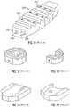
- FIGS. 1-22illustrate a variety of implants configured as intervertebral bodies and spacers, bone plates, pins, dowels, and the like, according to embodiments of the present disclosure.
- FIG. 23illustrates the distal end of an integral implant insertion instrument and implant, according to an embodiment of the present disclosure.
- FIG. 24shows an interbody implant having deployable teeth.
- FIG. 25shows a cross section of the interbody implant at the location of a deployable tooth. In this figure, the tooth is in the un-deployed state.
- FIG. 26shows a cross section of the interbody implant at the location of a deployable tooth. In this figure, the tooth is in the deployed state.
- Implants according to embodiments described hereinmay include interbody implants or fusion cages.
- the interbody implantsare typically intended to be placed between two vertebral bodies. Oftentimes, the intervertebral disc is removed prior to the placement of the interbody implant.
- the lower side of an interbody implantis intended to abut at least a portion of an upper side (endplate) of a first vertebral body and the upper side of the interbody implant is intended to abut at least a portion of a lower side (endplate) of a second vertebral body.
- Insufficient contact and load transfer between the vertebral body and the interbody implantcan produce inadequate fixation and can allow the cage to move relative to the vertebral body. Furthermore, insufficient contact area or fixation between the interbody implant and the vertebral bodies can result in micro-motions and/or macro-motions that can reduce the opportunity for bone growth and fusion to occur. If enough motion occurs, expulsion of the interbody implant can result.
- fixation elementsincluding teeth, barbs, or screws
- fixation elementscan be used to provide fixation of the interbody implant to the adjacent vertebral bodies.
- These fixation elementscan be static features, such as teeth, on the opposing surfaces of the interbody that are designed to contact the vertebral endplates.
- screws or barbscan be delivered following delivery and placement of the interbody implant. In these cases, these screws and barbs are driven through openings in the interbody implant and into the adjacent vertebral bodies.
- Each of these elements and featuresare designed to create fixation between the implant and adjacent anatomy.
- Low bone mineral density index, overaggressive discectomies, or decortications of the endplatecan reduce the strength of the anatomic endplate and reduce the ability to provide sufficient fixation to the interbody implant and reduce the transfer load from one vertebral body to another.
- surgeonscarefully prepare the opposing vertebral endplates. The surgeon aims to insert an interbody implant having as large a footprint (coverage area) as possible, in order to maximize the contact surface between implant and anatomy.
- the surgeonalso places the interbody implant on the apophyseal rings to provide as much support and load transfer as possible for spinal distraction. The surgeon must also ensure the interbody implant is securely positioned within the disc space.
- FIGS. 1-22illustrate a variety of implants which may be produced by the systems and methods described herein, according to several embodiments of the present disclosure.
- FIG. 1illustrates an intervertebral implant possessing biconvex surfaces 237 which are configured to match the curvatures of the vertebral endplates with which they come into contact.
- the biconvex surfaces 237may each curve laterally (left to right), or curve anteriorly-posteriorly, or curve both laterally and anteriorly-posteriorly (e.g., a hemisphere or other three-dimensional convex shape).
- FIGS. 2-6show various views of implants that are suitable for interbody use, including the oval footprints of FIGS. 2-3 , the hexagonal footprints of FIGS.
- FIG. 7shows a cervical bone plate for the fixation of adjacent cervical vertebrae.
- the bone platespans two or more vertebrae, but does not necessarily fill the space between two vertebral endplates.
- the size and shape of the bone plate of FIG. 7including the location of the holes for screws, may be configured to maintain the cervical vertebrae in a particular relation to each other.
- FIG. 8illustrates a cylindrical pin or dowel which may be keyed (not shown) to facilitate its installation.
- FIG. 9illustrates an intervertebral implant 240 having a textured surface 241 , e.g., roughenings, knurlings, ridges, and the like, to resist backing-out of the implant following its insertion in the intervertebral space.
- Surfaces 241may converge to provide an anterior ramp configuration possessing a suitable lordotic angle or the surfaces may be essentially flat.
- the outer profile 242 of the implantcan be round, oval, square, diamond-shaped, octagonal, hexagonal, etc., as requirements suggest.
- the implantcan be provided with an opening 243 for receiving a quantity of osteogenic/osteoinductive material and/or a rigid reinforcing member 244 for added strength.
- FIG. 10depicts an open, or cage-like, structure 245 suitable for use as an anterior or posterior intervertebral implant.
- Cross braces 246 on one or more sides of the implantprovide increased structural strength over that of a totally open configuration.
- the open spacecan be advantageously filled with an osteogenic/osteoinducting material.
- Texturized surfaces, e.g., ridges, 247are provided to resist backing-out of the implant following its installation.
- Inserter interface 248is intended to receive the distal (working end) of an implant insertion tool.
- FIG. 11illustrates an intervertebral implant 249 possessing a position-retaining textured surface 250 (ridges) and a pattern of orifices communicating with the interior which possesses a void structure.
- the sides of the implant at one end thereofhave a matching pair of implant inserter interfaces 252 which are intended to be grasped by an insertion tool.
- One end of the implantpossesses an orifice 249 a through which an osteogenic/osteoinductive material can be introduced into the interior void communicating channels of the implant.
- FIGS. 12-15show various additional configurations of implants for insertion in the intervertebral space: FIG. 12 (an anterior ramp implant), FIG. 13 (a posterior ramp implant), FIG. 14 (a cervical spacer) and FIG. 15 (a cervical spacer including a radiused recess at one side).
- FIGS. 16-18show various implants configured as intervertebral dowels.
- the implant of FIG. 16is a solid structure with a through bore for receiving osteogenic/osteoinductive material.
- the implant of FIG. 17possesses an open, or cage-like, structure which can be packed with osteogenic/osteoinductive material.
- the implant of FIG. 18possesses at least one wing-like structure 253 on its longitudinal surface which prevents rotational displacement within the intervertebral space.
- FIG. 19illustrates a transforaminal lumbar interbody fusion (TLIF) implant and its assembly from subunits.
- the implant of FIG. 19may alternatively be used as a posterior lumbar interbody fusion (PLIF) implant.
- FIG. 20depicts a convex anterior interbody ramp with openings communicating with the interior.
- FIG. 21shows another embodiment of anterior interbody implant.
- FIG. 22shows a solid anterior interbody implant presenting a large surface area for implant-vertebral endplate contact.
- FIG. 23schematically illustrates in plan view the distal end 257 of an integral, or combined, implant insertion instrument and implant 256 wherein implant portion 258 specifically, an intervertebral implant, is joined to the distal end 257 of the instrument portion through a weakened, or break-away, site of attachment 259 .
- the site of attachment 259may comprise any mechanism that allows the distal end 257 to releasably grip or maintain the implant 258 , including, but not limited to: a clamp, an adhesive, epoxy, or hot melt attachment, a magnetic connection, a snap, a threaded attachment, a tapered attachment, a spring attachment, and a combination of any two or more of these attachment features.
- Custom instrumentsmay even be produced by the systems and methods described herein. For example, a particular patient may have a deformity which requires an instrument having a particular angle that is not available in off-the-shelf instruments.
- FIG. 24shows an interbody implant 200 having opposing bone contacting surfaces 201 , opposing lateral surfaces 203 , an anterior surface 205 , and a posterior surface 207 .
- Surfaces 201 , 203 , 205 , 207form a three-dimensional implant 200 .
- Surfaces 201 , 203 , 205 , 207can be planar or curved. When curved, the surfaces 201 , 203 , 205 , 207 may each comprise a concave surface or a convex surface. In some embodiments, the surfaces 201 , 203 , 205 , 207 can become contiguous and uninterrupted. In some cases, the cross section can be circular, semi-circular, U-shaped, or C-shaped.
- implant 200contains static fixation features 204 , and dynamic fixation features 202 extending from a base portion 226 of the implant 200 .
- Static teeth 204are configured to provide temporary fixation between the interbody implant 200 and a first adjacent vertebral body.
- Dynamic teeth 202are deployed after delivery of the implant 200 to a desired location within the intervertebral space, and configured to provide fixation to a second adjacent vertebral body.
- implant 200is inserted into the intervertebral space and adjusted to the location using insertion and adjustment tools.
- the toolscan be designed to mate with features 208 a , 208 b on the interbody implant 200 .
- Features 208 a , 208 bmay comprise indentations, grooves, ribs, bumps, or other geometric designs to which tools may be engaged.
- FIG. 25shows a cross section of a dynamic tooth 202 in a first position relative to opening 231 (undeployed).
- tooth 202is positioned sub-flush relative the surface of implant 200 .
- Additive manufacturing processesare utilized which enable fabrication of features 230 , 232 , teeth 202 , bridges 224 to create a mechanism that can be optimized to provide dynamic teeth 202 .
- Additive manufacturing processesmay include one or more of: three-dimensional printing, vat polymerization, stereolithography (SLA), selective laser melting (SLM), powder bed printing (PP), powder bed fusion, sheet laminarization, material extrusion, selective laser sintering (SLS), selective heat sintering (SHM), fused deposition modeling (FDM), direct metal laser sintering (DMLS), laminated object manufacturing (LOM), laminar deposition, thermoplastic printing, direct material deposition (DMD), digital light processing (DLP), inkjet photo resin machining, and electron beam melting (EBM).
- SLAstereolithography
- SLMselective laser melting
- PPpowder bed printing
- SLSselective heat sintering
- FDMfused deposition modeling
- DMLSdirect metal laser sintering
- LOMlaminated object manufacturing
- laminar depositionthermoplastic printing
- DMDdirect material deposition
- DLPdigital light processing
- EBMelectron beam melting
- Additive manufacturing, building parts layer-by-layercan be used to create features 230 , 232 , teeth 202 , bridges 224 of a mechanism that can be optimized to create, first, a break-away (separation of tooth 202 from the base portion 226 of the implant 200 ) and, after break-away, a seized relationship between the base portion 226 of the implant 200 and the tooth 202 .
- Another advantage of employing additive manufacturingis the ability to create patient-specific implants that are designed to optimally fit each patient.
- the implant 200may include any of the embodiments described herein, or may include embodiments of implants or may incorporate the methods for designing and making implants, such as those disclosed in co-pending U.S. patent application Ser. No. 16/207,116, filed on Dec. 1, 2018, and entitled “Systems and Methods for Multi-Planar Orthopedic Alignment,” which is incorporated by reference herein in its entirety for all purposes.
- scan datais obtained from a CT scan of a patient, for example, a CT scan that includes the spine of the patient, or at least the portion of interest in the spine.
- the scan datamay comprise MRI scan data or x-ray data.
- the CT scan datais converted into a three-dimensional image through software manipulation of the data.
- CT scan datais presented in a DICOM format, which includes individual slices of imaging data.
- a common slide thicknessis one mm, though other thickness may be used, such as 0.25 mm, 0.5 mm, 1.5 mm, 2.0 mm, 2.5 mm, 3.0 mm and greater thicknesses.
- Spine segmentsmay be selected for analysis.
- a user interfacethat is associated with at least one computer memory that is not a transitory signal and which comprises instructions executable by at least one processor may be utilized to select a region of interest.
- the region of interestmay be a diseased or deformed portion of the spine, including a particular number of successive vertebrae and their surrounding soft tissue.
- the entire spinemay be selected.
- only sacral and lumbar vertebrae and their surrounding soft tissueare selected.
- only lumbar and thoracic vertebrae and their surrounding soft tissueare selected.
- only cervical vertebrae and their surrounding soft tissueare selected.
- the systemmay contain a memory and a processor, and may include any number of custom stand-alone devices, or any mobile device, such as an iPhone, smart phone, iPAD, smart watch, laptop or desktop computer.
- the systemmay also include a user interface.
- the systemmay also be configured to access the memory remotely, for example, via internet browser access or other wireless means.
- the three-dimensional imagecan be converted into a form such that it can be manipulated by a user to measure anatomical deformities related to the disease (e.g., spine disease).
- the informationcan then be used by a medical professional, or technical or engineering professional in conjunction or collaboration with a medical professional, to design the optimized geometry of the corrected spine, thus allowing the design of an implant to treat the particular disease or malady.
- the teeth 202can be temporarily affixed to the base portion 226 of the implant body 200 (e.g., via the bridges 224 which extend between each tooth 224 and the base portion 206 of the implant 200 ).
- the tip 228 of each tooth 202is positioned within recess 229 and opening 231 at or near the surface 206 of the implant 200 .
- tips 228 of teeth 202are positioned below the surface 206 of implant 200 (sub-flush). In this embodiment, tips 228 are protected and are not subjected to loads during insertion and positioning of the implant 200 .
- tips 228can be made sharp and can remain sharp in order to penetrate adjacent anatomy and provide fixation.
- a tool 211can be used to deploy teeth 202 to a position that is super-flush relative to the surface 206 .
- the tool 211may have a tip 213 configured to insert into feature 208 a to apply a force to cause both separation of the tooth 202 from the base portion 206 of the implant 200 , and to cause the tooth 202 to be extended from its flush or sub-flush position (e.g., the first, undeployed position).
- an axial force 220can be delivered to tooth 202 with the tool 221 .
- the tool 221may be configured to apply a torque, as does a screwdriver, that in turn places an axial force 220 on the tooth 202 .
- the tool 221may be configured to apply a force along an axis extending between two surfaces (e.g., along an axis extending between the anterior surface 205 and the posterior surface 207 ) in order to release a spring element or other element that transversely applies an axial force 220 on the tooth 202 .
- the axial force 220causes the tooth 202 to move in an axial direction 222 to extend from the surface 206 and penetrate the adjacent vertebral endplate.
- tooth 202may be connected to implant 200 with a break-away bridge 224 or a series of break-away bridges 224 .
- Axial force 220can fracture bridge 224 and allow axial translation 222 of tooth 202 .
- Locking features 230 , 232can be positioned on tooth 202 and implant 200 to provide fixation between implant 200 and tooth 202 .
- Locking features 230 , 232may comprise protrusions 230 and indentations 232 , configured to fit into each other.
- the protrusions 230may be configured to permanently snap permanently into the indentations 232 .
- the protrusions 230may be configured to removably fit into the indentations 232 .
- the protrusions 230when snapped into the indentations 232 may have a minimum unsnapping force of at least about 50 pounds.
- the protrusions 230 and indentations 232may each have lead-ins (e.g. tapers) that each the snapping of the protrusion 230 into the indentation 232 , but not have lead-ins on the opposite sides of the protrusions 230 and indentations 232 , such that unsnapping is not possible, or is at least very difficult or requires an unlikely high force to achieve.
- FIG. 26shows a cross section of the tooth 202 in a second position (fully deployed).
- tooth 202is deployed and wedged or engaged into position.
- the sizing of opening 231 in relation to the tooth 202is such that the tooth cannot be expulsed from the opening 231 .
- expulsion of the toothcannot occur because the opening 231 is smaller than the dimensions at the larger end of tooth 202 (bottom of FIG. 26 ).
- the sizing of tooth 202 and opening 231is such that tooth 202 cannot be permanently disassociated from the implant due to the fit of tooth 202 within opening 231 .
- the post-deployment relationship between tooth 202 and implant 200is preserved using interference fits between locking features 230 , 232 and/or surfaces 235 , 236 .
- the locking features 230 , 232are absent, and instead, the tooth 202 frictionally engages within the recess 229 (via surfaces 230 , 232 ) at the base portion 226 when the tooth 202 is axially extended.
- flash (remaining material) from the broken break-away bridges 224may provide the slight interference with which the tooth 202 frictionally engages with the recess 229 .
- the features 230 , 232may include bumps, recesses, annual grooves, ridges, rings, incomplete rings, split rings, buttons, springs, or other three-dimensional features to provide secure engagement between tooth 202 and implant 200 .
- Other mechanisms, such as friction, interference, and deformation between surfaces of tooth 202 and opening 231can seize the relationship between components.
- the bridge 224may comprise a break-away adhesive joint, a break-away tack or weld, or a magnetic coupling.
- the bridge 224may comprise a flexible joint, an over-center mechanism, a linkage, any of which may include a locked condition and an unlocked condition.
- the locked conditionmay be the condition when delivered and the unlocked condition may be achieved by the application of a substantially axially-directed force placed upon the tooth 202 or upon the bridge 224 or upon the tooth 202 and the bridge 224 .
- a non-axially directed force or a momente.g., torque
- Interbody 200can be manufactured of materials typical of medical implants, including, but not limited to, titanium, titanium alloy, Ti6Al4V, polymers, polyether ether ketone (PEEK), etc.
- the systems and methods described hereinare configured to provide a three-dimensional shape that represents the ideal implant to fit into the negative space of the spine, once the spine receives the appropriate manipulation in the coronal, sagittal, and axial planes.
- the custom shape of the implantwill at least partially provide and maintain the desired correction to the spine.
- the coronal, sagittal, and axial plane deformities of the spineare corrected, allowing restoration of the anatomical function of the spine.
- the correctionmay include both rotation and/or linear displacement along the degrees of freedom.
- ranges disclosed hereinalso encompass any and all overlap, sub-ranges, and combinations thereof.
- the terms “approximately”, “about”, and “substantially”may refer to an amount that is within less than 10% of, within less than 5% of, within less than 1% of, within less than 0.1% of, and within less than 0.01% of the stated amount.
Landscapes
- Health & Medical Sciences (AREA)
- Engineering & Computer Science (AREA)
- Biomedical Technology (AREA)
- Orthopedic Medicine & Surgery (AREA)
- Neurology (AREA)
- Heart & Thoracic Surgery (AREA)
- Oral & Maxillofacial Surgery (AREA)
- Transplantation (AREA)
- Cardiology (AREA)
- Vascular Medicine (AREA)
- Life Sciences & Earth Sciences (AREA)
- Animal Behavior & Ethology (AREA)
- General Health & Medical Sciences (AREA)
- Public Health (AREA)
- Veterinary Medicine (AREA)
- Prostheses (AREA)
Abstract
Description
Claims (17)
Priority Applications (2)
| Application Number | Priority Date | Filing Date | Title |
|---|---|---|---|
| US16/352,699US11432943B2 (en) | 2018-03-14 | 2019-03-13 | Systems and methods for orthopedic implant fixation |
| US17/875,699US20230052263A1 (en) | 2018-03-14 | 2022-07-28 | Systems and methods for orthopedic implant fixation |
Applications Claiming Priority (2)
| Application Number | Priority Date | Filing Date | Title |
|---|---|---|---|
| US201862643046P | 2018-03-14 | 2018-03-14 | |
| US16/352,699US11432943B2 (en) | 2018-03-14 | 2019-03-13 | Systems and methods for orthopedic implant fixation |
Related Child Applications (1)
| Application Number | Title | Priority Date | Filing Date |
|---|---|---|---|
| US17/875,699ContinuationUS20230052263A1 (en) | 2018-03-14 | 2022-07-28 | Systems and methods for orthopedic implant fixation |
Publications (2)
| Publication Number | Publication Date |
|---|---|
| US20190282367A1 US20190282367A1 (en) | 2019-09-19 |
| US11432943B2true US11432943B2 (en) | 2022-09-06 |
Family
ID=67904790
Family Applications (2)
| Application Number | Title | Priority Date | Filing Date |
|---|---|---|---|
| US16/352,699Active2039-04-17US11432943B2 (en) | 2018-03-14 | 2019-03-13 | Systems and methods for orthopedic implant fixation |
| US17/875,699PendingUS20230052263A1 (en) | 2018-03-14 | 2022-07-28 | Systems and methods for orthopedic implant fixation |
Family Applications After (1)
| Application Number | Title | Priority Date | Filing Date |
|---|---|---|---|
| US17/875,699PendingUS20230052263A1 (en) | 2018-03-14 | 2022-07-28 | Systems and methods for orthopedic implant fixation |
Country Status (1)
| Country | Link |
|---|---|
| US (2) | US11432943B2 (en) |
Cited By (10)
| Publication number | Priority date | Publication date | Assignee | Title |
|---|---|---|---|---|
| US11678938B2 (en) | 2020-01-06 | 2023-06-20 | Carlsmed, Inc. | Patient-specific medical systems, devices, and methods |
| US11717412B2 (en) | 2018-09-12 | 2023-08-08 | Carlsmed, Inc. | Systems and methods for orthopedic implants |
| US11793577B1 (en) | 2023-01-27 | 2023-10-24 | Carlsmed, Inc. | Techniques to map three-dimensional human anatomy data to two-dimensional human anatomy data |
| US11806241B1 (en) | 2022-09-22 | 2023-11-07 | Carlsmed, Inc. | System for manufacturing and pre-operative inspecting of patient-specific implants |
| US11857264B2 (en) | 2017-07-27 | 2024-01-02 | Carlsmed, Inc. | Systems and methods for physician designed surgical procedures |
| US11984205B2 (en) | 2022-02-23 | 2024-05-14 | Carlsmed, Inc. | Non-fungible token systems and methods for storing and accessing healthcare data |
| US12232980B2 (en) | 2021-06-08 | 2025-02-25 | Carlsmed, Inc. | Patient-specific expandable spinal implants and associated systems and methods |
| US12245952B2 (en) | 2018-04-16 | 2025-03-11 | Carlsmed, Inc. | Systems and methods for orthopedic implant fixation |
| US12274622B2 (en) | 2018-11-29 | 2025-04-15 | Carlsmed, Inc. | Systems and methods for orthopedic implants |
| US12390276B2 (en) | 2021-11-01 | 2025-08-19 | Carlsmed, Inc. | Spinal implants and surgical procedures with reduced subsidence, and associated systems and methods |
Families Citing this family (7)
| Publication number | Priority date | Publication date | Assignee | Title |
|---|---|---|---|---|
| US11112770B2 (en) | 2017-11-09 | 2021-09-07 | Carlsmed, Inc. | Systems and methods for assisting a surgeon and producing patient-specific medical devices |
| US11083586B2 (en) | 2017-12-04 | 2021-08-10 | Carlsmed, Inc. | Systems and methods for multi-planar orthopedic alignment |
| USD958151S1 (en) | 2018-07-30 | 2022-07-19 | Carlsmed, Inc. | Display screen with a graphical user interface for surgical planning |
| US10902944B1 (en) | 2020-01-06 | 2021-01-26 | Carlsmed, Inc. | Patient-specific medical procedures and devices, and associated systems and methods |
| IT202000014569A1 (en)* | 2020-06-18 | 2021-12-18 | Sps S R L | INTERSOMATIC CAGE FOR VERTEBRAL STABILIZATION |
| US12226315B2 (en) | 2020-08-06 | 2025-02-18 | Carlsmed, Inc. | Kinematic data-based patient-specific artificial discs, implants and associated systems and methods |
| WO2022109259A1 (en) | 2020-11-20 | 2022-05-27 | Carlsmed, Inc. | Patient-specific jig for personalized surgery |
Citations (159)
| Publication number | Priority date | Publication date | Assignee | Title |
|---|---|---|---|---|
| US4704686A (en) | 1982-04-10 | 1987-11-03 | Aldinger Guenther | Method of manufacturing of individually formed prothesis or implant |
| US4936862A (en) | 1986-05-30 | 1990-06-26 | Walker Peter S | Method of designing and manufacturing a human joint prosthesis |
| US5431562A (en) | 1990-01-19 | 1995-07-11 | Ormco Corporation | Method and apparatus for designing and forming a custom orthodontic appliance and for the straightening of teeth therewith |
| US20020007294A1 (en) | 2000-04-05 | 2002-01-17 | Bradbury Thomas J. | System and method for rapidly customizing a design and remotely manufacturing biomedical devices using a computer system |
| US6696073B2 (en)* | 1999-02-23 | 2004-02-24 | Osteotech, Inc. | Shaped load-bearing osteoimplant and methods of making same |
| US6772026B2 (en) | 2000-04-05 | 2004-08-03 | Therics, Inc. | System and method for rapidly customizing design, manufacture and/or selection of biomedical devices |
| US20040171924A1 (en) | 2003-01-30 | 2004-09-02 | Mire David A. | Method and apparatus for preplanning a surgical procedure |
| WO2004110309A2 (en) | 2003-06-11 | 2004-12-23 | Case Western Reserve University | Computer-aided-design of skeletal implants |
| US20050049590A1 (en)* | 2003-03-07 | 2005-03-03 | Neville Alleyne | Spinal implant with securement spikes |
| US6932842B1 (en) | 1999-05-11 | 2005-08-23 | 3Di Gmbh | Method for generating patient-specific implants |
| US20050271996A1 (en) | 2001-04-13 | 2005-12-08 | Orametrix, Inc. | Method and system for comprehensive evaluation of orthodontic care using unified workstation |
| US6978188B1 (en) | 2002-09-30 | 2005-12-20 | Medical Modeling, Llc | Method for contouring bone reconstruction plates |
| US20060009780A1 (en) | 1997-09-24 | 2006-01-12 | Foley Kevin T | Percutaneous registration apparatus and method for use in computer-assisted surgical navigation |
| US6988241B1 (en) | 2000-10-16 | 2006-01-17 | International Business Machines Corporation | Client side, web-based spreadsheet |
| US7174282B2 (en) | 2001-06-22 | 2007-02-06 | Scott J Hollister | Design methodology for tissue engineering scaffolds and biomaterial implants |
| US7187790B2 (en) | 2002-12-18 | 2007-03-06 | Ge Medical Systems Global Technology Company, Llc | Data processing and feedback method and system |
| US20070118243A1 (en) | 2005-10-14 | 2007-05-24 | Vantus Technology Corporation | Personal fit medical implants and orthopedic surgical instruments and methods for making |
| USD548242S1 (en) | 2006-05-22 | 2007-08-07 | Microsoft Corporation | User interface for a portion of a display screen |
| US20070276501A1 (en) | 2006-05-25 | 2007-11-29 | Spinemedica Corp. | Patient-specific spinal implants and related systems and methods |
| US20080161680A1 (en) | 2006-12-29 | 2008-07-03 | General Electric Company | System and method for surgical navigation of motion preservation prosthesis |
| US20080195240A1 (en) | 2007-02-13 | 2008-08-14 | Amanda Martin | Method of designing orthopedic plates and plates made in accordance with the method |
| US7756314B2 (en) | 2003-11-26 | 2010-07-13 | Ge Medical Systems Global Technology Company, Llc | Methods and systems for computer aided targeting |
| US20100191088A1 (en) | 2009-01-23 | 2010-07-29 | Warsaw Orthopedic, Inc. | Methods and systems for diagnosing, treating, or tracking spinal disorders |
| US7799077B2 (en) | 2002-10-07 | 2010-09-21 | Conformis, Inc. | Minimally invasive joint implant with 3-dimensional geometry matching the articular surfaces |
| US20100292963A1 (en) | 2009-04-15 | 2010-11-18 | James Schroeder | Personal fit medical implants and orthopedic surgical instruments and methods for making |
| WO2010151564A1 (en) | 2009-06-24 | 2010-12-29 | Bojarski Raymond A | Patient-adapted and improved orthopedic implants, designs and related tools |
| US20110218545A1 (en) | 2010-03-04 | 2011-09-08 | Biomet Manufacturing Corp. | Patient-specific computed tomography guides |
| US20110301710A1 (en) | 2010-06-02 | 2011-12-08 | Steven Mather | Intervertebral implant facilitating unilateral placement, instruments and methods |
| US20120010710A1 (en) | 2010-07-08 | 2012-01-12 | Robert Frigg | Advanced Bone Marker and Custom Implants |
| US20120084064A1 (en) | 2010-09-29 | 2012-04-05 | Nutech Ventures, Inc. | Model-based systems and methods for analyzing and predicting outcomes of vascular interventions and reconstructions |
| US20120116203A1 (en) | 2010-11-10 | 2012-05-10 | Wilfried Vancraen | Additive manufacturing flow for the production of patient-specific devices comprising unique patient-specific identifiers |
| US20120150243A9 (en) | 2006-08-31 | 2012-06-14 | Catholic Healthcare West (Chw) | Computerized Planning Tool For Spine Surgery and Method and Device for Creating a Customized Guide for Implantations |
| US20120191192A1 (en) | 2009-09-30 | 2012-07-26 | Industry Foundation Of Chonnam National University | Image-based patient-specific medical spinal surgery method and spinal prosthesis |
| US8265949B2 (en) | 2007-09-27 | 2012-09-11 | Depuy Products, Inc. | Customized patient surgical plan |
| US8275594B2 (en) | 2006-10-30 | 2012-09-25 | The Regents Of The University Of Michigan | Engineered scaffolds for intervertebral disc repair and regeneration and for articulating joint repair and regeneration |
| US20120287238A1 (en) | 2011-01-24 | 2012-11-15 | Olympus Medical Systems Corp. | Medical device |
| US20120296433A1 (en) | 2010-02-02 | 2012-11-22 | Azadeh Farin | Spine surgery device |
| US8337507B2 (en) | 2001-05-25 | 2012-12-25 | Conformis, Inc. | Methods and compositions for articular repair |
| US8394142B2 (en) | 2005-06-13 | 2013-03-12 | Synthes Usa, Llc | Customizing an intervertebral implant |
| US20130211531A1 (en) | 2001-05-25 | 2013-08-15 | Conformis, Inc. | Patient-adapted and improved articular implants, designs and related guide tools |
| US8532806B1 (en) | 2010-06-07 | 2013-09-10 | Marcos V. Masson | Process for manufacture of joint implants |
| US8556983B2 (en) | 2001-05-25 | 2013-10-15 | Conformis, Inc. | Patient-adapted and improved orthopedic implants, designs and related tools |
| US8644568B1 (en) | 2008-07-25 | 2014-02-04 | O.N.Diagnostics, LLC | Automated patient-specific bone-implant biomechanical analysis |
| US20140072608A1 (en) | 2012-08-30 | 2014-03-13 | Stergios Logothetidis | Method for production of nanoporous multi-layer biodegradable polymeric coatings and products thereof |
| US20140074438A1 (en) | 2012-09-12 | 2014-03-13 | André Furrer | Method for producing patient-specific plate |
| US20140081659A1 (en) | 2012-09-17 | 2014-03-20 | Depuy Orthopaedics, Inc. | Systems and methods for surgical and interventional planning, support, post-operative follow-up, and functional recovery tracking |
| US20140086780A1 (en) | 2012-09-21 | 2014-03-27 | Conformis, Inc. | Methods and systems for optimizing design and manufacture of implant components using solid freeform fabrication |
| US8735773B2 (en) | 2007-02-14 | 2014-05-27 | Conformis, Inc. | Implant device and method for manufacture |
| US20140164022A1 (en) | 2012-12-10 | 2014-06-12 | Atlantic Health System, Inc., a NJ non-profit corporation | Patient Directed Healthcare System |
| US8758357B2 (en) | 2010-06-29 | 2014-06-24 | George Frey | Patient matching surgical guide and method for using the same |
| US8781557B2 (en) | 1999-08-11 | 2014-07-15 | Osteoplastics, Llc | Producing a three dimensional model of an implant |
| US8843229B2 (en) | 2012-07-20 | 2014-09-23 | Biomet Manufacturing, Llc | Metallic structures having porous regions from imaged bone at pre-defined anatomic locations |
| US8870889B2 (en) | 2010-06-29 | 2014-10-28 | George Frey | Patient matching surgical guide and method for using the same |
| WO2014180972A2 (en) | 2013-05-08 | 2014-11-13 | Materialise N.V. | System and method for three-dimensional population analysis of anatomic structures |
| US20140350614A1 (en) | 2013-03-15 | 2014-11-27 | George Frey | Patient-matched apparatus and methods for performing surgical procedures |
| CN104318009A (en) | 2014-10-20 | 2015-01-28 | 北京航空航天大学 | Method for designing personalized interbody fusion cage |
| CN104353121A (en) | 2014-11-24 | 2015-02-18 | 吴志宏 | BMP microsphere loaded 3D printing porous metal stent and preparation method thereof |
| US20150105891A1 (en) | 2013-10-11 | 2015-04-16 | Advanced Solutions Life Sciences, Llc | System and workstation for the design, fabrication and assembly of bio-material constructs |
| US9020788B2 (en) | 1997-01-08 | 2015-04-28 | Conformis, Inc. | Patient-adapted and improved articular implants, designs and related guide tools |
| CN204468348U (en) | 2014-12-22 | 2015-07-15 | 深圳市第二人民医院 | A kind of personalized 3D prints polythene material Invasive lumbar fusion device |
| US20150305878A1 (en)* | 2014-04-24 | 2015-10-29 | DePuy Synthes Products, LLC | Patient-Specific Spinal Fusion Cage and Methods of Making Same |
| US20150324490A1 (en) | 2014-05-09 | 2015-11-12 | Autodesk, Inc. | User specific design customization for 3d printing |
| US20150328004A1 (en) | 2013-10-15 | 2015-11-19 | Mohamed Rashwan Mafhouz | Bone Reconstruction and Orthopedic Implants |
| US9208558B2 (en) | 1999-08-11 | 2015-12-08 | Osteoplastics Llc | Methods and systems for producing an implant |
| US20160015465A1 (en) | 2013-03-15 | 2016-01-21 | Conformis, Inc. | Historical Patient-Specific Information for Articular Repair Systems |
| US20160074048A1 (en) | 2008-04-30 | 2016-03-17 | Howmedica Osteonics Corporation | System and method for image segmentation in generating computer models of a joint to undergo arthroplasty |
| US20160117817A1 (en) | 2014-10-24 | 2016-04-28 | Hectec Gmbh | Method of planning, preparing, supporting, monitoring and/or subsequently checking a surgical intervention in the human or animal body, apparatus for carrying out such an intervention and use of the apparatus |
| USD761842S1 (en) | 2014-06-03 | 2016-07-19 | Microsoft Corporation | Display screen with transitional graphical user interface |
| US20160210374A1 (en) | 2013-09-18 | 2016-07-21 | Medicrea International | Method making it possible to produce the ideal curvature of a rod of vertebral osteosynthesis material designed to support a patient's vertebral column |
| CN105796214A (en) | 2016-03-08 | 2016-07-27 | 吴志宏 | Porous metal cervical interbody fusion cage for directionally and slowly releasing rhBMP-2 |
| US20160217268A1 (en) | 2008-09-19 | 2016-07-28 | Smith & Nephew, Inc. | Operatively tuning implants for increased performance |
| US20160242857A1 (en) | 2015-02-13 | 2016-08-25 | Nuvasive, Inc. | Systems and methods for planning, performing, and assessing spinal correction during surgery |
| US9445907B2 (en) | 2011-03-07 | 2016-09-20 | Biomet Manufacturing, Llc | Patient-specific tools and implants |
| US9452050B2 (en) | 2011-02-25 | 2016-09-27 | Corin Limited | Method incorporating computer-implemented steps, a computing device and a computer readable storage medium for developing manufacturing parameters for manufacturing an orthopaedic implant |
| US20160300026A1 (en) | 2015-04-13 | 2016-10-13 | Siemens Medical Solutions Usa, Inc. | Patient Management Based On Anatomic Measurements |
| WO2016172694A1 (en) | 2015-04-23 | 2016-10-27 | Richard Van Bibber | Devices and methods for anatomic mapping for prosthetic implants |
| US20160354039A1 (en) | 2004-03-05 | 2016-12-08 | Health Outcomes Sciences, Inc. | Systems and methods for utilizing wireless physiological sensors |
| US20160378919A1 (en) | 2013-11-27 | 2016-12-29 | The Johns Hopkins University | System and method for medical data analysis and sharing |
| US20170000566A1 (en) | 2013-11-29 | 2017-01-05 | The Johns Hopkins University | Computer-assisted face-jaw-teeth transplantation |
| US9542525B2 (en) | 2014-06-24 | 2017-01-10 | Siemens Product Lifecycle Management Software Inc. | Additive smoothing of sharp concave edges on designed 3D printable polygonal mesh models |
| US20170014169A1 (en) | 2014-03-11 | 2017-01-19 | Ohio State Innovation Foundation | Methods, devices, and manufacture of the devices for musculoskeletal reconstructive surgery |
| EP3120796A1 (en) | 2015-07-17 | 2017-01-25 | Mimedis AG | Method and system for the manufacture of an implant |
| US20170035514A1 (en) | 2015-08-07 | 2017-02-09 | Abbott Cardiovascular System Inc. | System and method for supporting decisions during a catheterization procedure |
| US20170061375A1 (en) | 2014-08-01 | 2017-03-02 | Smith & Nephew, Inc. | Providing implants for surgical procedures |
| US20170068792A1 (en) | 2015-09-03 | 2017-03-09 | Bruce Reiner | System and method for medical device security, data tracking and outcomes analysis |
| US9642633B2 (en) | 2010-06-29 | 2017-05-09 | Mighty Oak Medical, Inc. | Patient-matched apparatus and methods for performing surgical procedures |
| US20170135706A1 (en) | 2010-06-29 | 2017-05-18 | Mighty Oak Medical, Inc. | Patient-matched apparatus and methods for performing surgical procedures |
| US20170143494A1 (en) | 2014-07-10 | 2017-05-25 | Mohamed R. Mahfouz | Bone Reconstruction and Orthopedic Implants |
| US20170143831A1 (en) | 2015-11-24 | 2017-05-25 | The Texas A&M University System | In vivo live 3d printing of regenerative bone healing scaffolds for rapid fracture healing |
| US9693831B2 (en) | 2013-10-18 | 2017-07-04 | Medicrea International | Method making it possible to produce the ideal curvature of a rod of vertebral osteosynthesis material designed to support a patient vertebral column |
| US9707058B2 (en) | 2009-07-10 | 2017-07-18 | Zimmer Dental, Inc. | Patient-specific implants with improved osseointegration |
| US20170216047A1 (en) | 2008-02-11 | 2017-08-03 | Nexus TDR, Inc. | Systems and Methods for Patient-Specific Total Disc Replacement |
| US20170220740A1 (en) | 2014-08-05 | 2017-08-03 | Paul S. D'Urso | System for delivering personalized health care |
| US20170252107A1 (en) | 2016-03-02 | 2017-09-07 | Nuvasive, Inc. | Systems and Methods for Spinal Correction Surgical Planning |
| US20170262595A1 (en) | 2008-02-20 | 2017-09-14 | Mako Surgical Corp. | Implant planning using corrected captured joint motion information |
| US20170367645A1 (en) | 2015-01-16 | 2017-12-28 | Koninklijke Philips N.V. | Vertebral feature identification |
| US20180008349A1 (en) | 2016-07-11 | 2018-01-11 | Bullseye Hip Replacement, Llc | Methods to assist with medical procedures by utilizing patient-specific devices |
| US20180116727A1 (en) | 2016-11-02 | 2018-05-03 | Rochester Institute Of Technology | Method and fixture for guided pedicle screw placement |
| US20180168731A1 (en) | 2015-05-29 | 2018-06-21 | The Penn State Research Foundation | Individualized preoperative planning system and method |
| US20180168499A1 (en) | 2015-06-04 | 2018-06-21 | Peter John BERGOLD | Diagnosis of mild traumatic brain injury |
| US20180185075A1 (en) | 2015-06-09 | 2018-07-05 | Cheng Xin She | Fixing Bone Plate |
| US10034676B2 (en) | 2010-01-13 | 2018-07-31 | Jcbd, Llc | Systems for and methods of fusing a sacroiliac joint |
| US20180233225A1 (en) | 2017-02-15 | 2018-08-16 | Humetrix.Com, Inc. | Patient-facing mobile technology to assist physician achieve quality measures for value-based payment |
| US20180233222A1 (en) | 2017-02-16 | 2018-08-16 | Mako Surgical Corporation | Surgical procedure planning system with multiple feedback loops |
| US20180250075A1 (en) | 2017-03-05 | 2018-09-06 | Samuel Cho | Architecture, system, and method for developing and robotically performing a medical procedure activity |
| US10089413B2 (en) | 2011-12-23 | 2018-10-02 | Materialise Nv | Systems and methods for designing and generating devices using accuracy maps and stability analysis |
| CN108670506A (en) | 2018-06-01 | 2018-10-19 | 苏州市康力骨科器械有限公司 | Suspension custom assembled total sacral prosthesis and custom method |
| US20180303616A1 (en) | 2017-04-21 | 2018-10-25 | Warsaw Orthopedic, Inc. | 3-d printing of bone grafts |
| US20180303552A1 (en) | 2017-04-21 | 2018-10-25 | Medicrea International | Systems, methods, and devices for developing patient-specific spinal treatments, operations, and procedures |
| US20180338841A1 (en)* | 2017-05-25 | 2018-11-29 | Stryker European Holdings I, Llc | Fusion Cage With Integrated Fixation And Insertion Features |
| US20190029757A1 (en) | 2017-07-27 | 2019-01-31 | Precisive Surgical, Inc. | Systems and methods for assisting and augmenting surgical procedures |
| US10213311B2 (en) | 2009-02-25 | 2019-02-26 | Zimmer Inc. | Deformable articulating templates |
| USD841675S1 (en) | 2017-03-31 | 2019-02-26 | Experian Health, Inc. | Display screen with a graphical user interface |
| USD845974S1 (en) | 2016-12-30 | 2019-04-16 | Adobe Inc. | Graphical user interface for displaying a marketing campaign on a screen |
| USD845973S1 (en) | 2016-06-09 | 2019-04-16 | Cfph, Llc | Display screen or portion thereof with a graphical user interface |
| USD847165S1 (en) | 2017-02-08 | 2019-04-30 | Csi Enterprises, Inc. | Display screen or portion thereof with graphical user interface |
| USD848468S1 (en) | 2017-12-13 | 2019-05-14 | Adp, Llc | Display screen with a transitional graphical user interface |
| US20190146458A1 (en) | 2017-11-09 | 2019-05-16 | Precisive Surgical, Inc. | Systems and methods for assisting a surgeon and producing patient-specific medical devices |
| USD849029S1 (en) | 2016-12-30 | 2019-05-21 | Adobe Inc. | Display screen with graphical user interface for a marketing campaign |
| USD849773S1 (en) | 2017-11-27 | 2019-05-28 | Allstate Insurance Company | Display screen with graphical user interface |
| US10299863B2 (en) | 2015-06-16 | 2019-05-28 | Siemens Healthcare Gmbh | Method and computing unit for generating a manufacturing model |
| US20190167435A1 (en) | 2017-12-04 | 2019-06-06 | Carlsmed, Inc. | Systems and methods for multi-planar orthopedic alignment |
| US20190201106A1 (en) | 2018-01-04 | 2019-07-04 | Holo Surgical Inc. | Identification and tracking of a predefined object in a set of images from a medical image scanner during a surgical procedure |
| WO2019148154A1 (en) | 2018-01-29 | 2019-08-01 | Lang Philipp K | Augmented reality guidance for orthopedic and other surgical procedures |
| US10390958B2 (en) | 2014-03-11 | 2019-08-27 | Douglas Stafford Maclennan | Artificial intervertebral disc implant device |
| US20190262084A1 (en) | 2018-02-27 | 2019-08-29 | NavLab, Inc. | Artificial intelligence guidance system for robotic surgery |
| USD860238S1 (en) | 2018-03-28 | 2019-09-17 | Innoplexus Ag | Display screen with transitional graphical user interface |
| USD860237S1 (en) | 2018-03-23 | 2019-09-17 | Revotek Co., Ltd | Display screen or portion thereof with graphical user interface |
| US20190321193A1 (en) | 2018-04-16 | 2019-10-24 | Carlsmed, Inc. | Systems and methods for orthopedic implant fixation |
| USD867379S1 (en) | 2017-06-20 | 2019-11-19 | Brainlab Ag | Display screen with graphical user interface for medical software |
| USD867389S1 (en) | 2016-11-07 | 2019-11-19 | Illumina, Inc. | Display screen or portion thereof with zygosity icon |
| CN110575289A (en) | 2019-09-20 | 2019-12-17 | 重庆新索医药科技有限公司 | A 3D printing method for bone defect prosthesis |
| US10512546B2 (en) | 2015-01-12 | 2019-12-24 | Ao Technology Ag | Method for manufacturing an auxiliary device suitable for the manufacture of a patient customized implant |
| USD870762S1 (en) | 2016-05-18 | 2019-12-24 | Airnguru S.A. | Display screen with animated graphical user interface for determining price competitiveness |
| USD872117S1 (en) | 2018-03-29 | 2020-01-07 | Mitsubishi Electric Corporation | Display screen with graphical user interface |
| USD872756S1 (en) | 2013-12-13 | 2020-01-14 | Kbc Advanced Technologies Limited | Display screen with graphical user interface for workflow |
| USD874490S1 (en) | 2009-07-03 | 2020-02-04 | Twitter, Inc. | Media sharing device display screen with transitional graphical user interface |
| USD875761S1 (en) | 2018-05-12 | 2020-02-18 | Canva Pty Ltd. | Display screen or portion thereof with a graphical user interface |
| USD876454S1 (en) | 2017-11-22 | 2020-02-25 | General Electric Company | Display screen with graphical user interface for an imaging protocol manager |
| USD877167S1 (en) | 2017-11-22 | 2020-03-03 | General Electric Company | Display screen with graphical user interface for an imaging protocol manager |
| US20200078180A1 (en) | 2018-09-12 | 2020-03-12 | Carlsmed, Inc. | Systems and methods for orthopedic implants |
| US10588589B2 (en) | 2014-07-21 | 2020-03-17 | Zebra Medical Vision Ltd. | Systems and methods for prediction of osteoporotic fracture risk |
| USD879112S1 (en) | 2017-11-14 | 2020-03-24 | Geographic Services, Inc. | Display screen or portion thereof with graphical user interface |
| US10603055B2 (en) | 2017-09-15 | 2020-03-31 | Jcbd, Llc | Systems for and methods of preparing and fusing a sacroiliac joint |
| USD880513S1 (en) | 2018-07-26 | 2020-04-07 | Delta Electronics, Inc. | Display screen with graphical user interface |
| USD881908S1 (en) | 2017-06-12 | 2020-04-21 | Unisys Corporation | Display screen with graphical user interface for network status |
| USD881910S1 (en) | 2017-12-18 | 2020-04-21 | Chyng Hong Electronic Co., Ltd. | Display screen with graphical user interface |
| US10631988B2 (en) | 2016-07-18 | 2020-04-28 | Sail Fusion, Llc | Implant and method for posterior sacroiliac fusion |
| US10646258B2 (en) | 2010-01-13 | 2020-05-12 | Jcbd, Llc | Implant assembly for low profile spinopelvic fixation and sacroiliac joint fusion |
| US20200170802A1 (en) | 2018-11-29 | 2020-06-04 | Carlsmed, Inc. | Systems and methods for orthopedic implants |
| CN111281613A (en) | 2020-02-16 | 2020-06-16 | 华中科技大学同济医学院附属协和医院 | 3D printing-based bionic porous artificial vertebral body preparation method |
| US10736698B2 (en) | 2017-05-30 | 2020-08-11 | Dignity Health | Systems and methods for constructing a synthetic anatomical model with predetermined anatomic, biomechanical, and physiological properties |
| US10751188B2 (en) | 2016-07-08 | 2020-08-25 | Beijing AK Medical Co., Ltd. | Sacral prosthesis |
| US20200315708A1 (en) | 2019-04-02 | 2020-10-08 | Medicrea International | Systems, methods, and devices for developing patient-specific spinal implants, treatments, operations, and/or procedures |
| US10806597B2 (en) | 2016-03-30 | 2020-10-20 | Medicrea International | Method for making an implant, notably a vertebral or intervertebral implant, and implant obtained by this method |
| CN112155792A (en) | 2020-10-29 | 2021-01-01 | 华中科技大学同济医学院附属同济医院 | Individualized artificial sacrum prosthesis based on additive manufacturing |
| US10902944B1 (en) | 2020-01-06 | 2021-01-26 | Carlsmed, Inc. | Patient-specific medical procedures and devices, and associated systems and methods |
| US20210059822A1 (en) | 2018-09-12 | 2021-03-04 | Carlsmed, Inc. | Systems and methods for designing orthopedic implants based on tissue characteristics |
| US11000334B1 (en) | 2017-07-12 | 2021-05-11 | K2M, Inc. | Systems and methods for modeling spines and treating spines based on spine models |
Family Cites Families (1)
| Publication number | Priority date | Publication date | Assignee | Title |
|---|---|---|---|---|
| CN108289660B (en)* | 2015-10-13 | 2021-07-27 | 马佐尔机器人有限公司 | Global spinal alignment method |
- 2019
- 2019-03-13USUS16/352,699patent/US11432943B2/enactiveActive
- 2022
- 2022-07-28USUS17/875,699patent/US20230052263A1/enactivePending
Patent Citations (181)
| Publication number | Priority date | Publication date | Assignee | Title |
|---|---|---|---|---|
| US4704686A (en) | 1982-04-10 | 1987-11-03 | Aldinger Guenther | Method of manufacturing of individually formed prothesis or implant |
| US4936862A (en) | 1986-05-30 | 1990-06-26 | Walker Peter S | Method of designing and manufacturing a human joint prosthesis |
| US5431562A (en) | 1990-01-19 | 1995-07-11 | Ormco Corporation | Method and apparatus for designing and forming a custom orthodontic appliance and for the straightening of teeth therewith |
| US9020788B2 (en) | 1997-01-08 | 2015-04-28 | Conformis, Inc. | Patient-adapted and improved articular implants, designs and related guide tools |
| US20060009780A1 (en) | 1997-09-24 | 2006-01-12 | Foley Kevin T | Percutaneous registration apparatus and method for use in computer-assisted surgical navigation |
| US6696073B2 (en)* | 1999-02-23 | 2004-02-24 | Osteotech, Inc. | Shaped load-bearing osteoimplant and methods of making same |
| US6932842B1 (en) | 1999-05-11 | 2005-08-23 | 3Di Gmbh | Method for generating patient-specific implants |
| US8781557B2 (en) | 1999-08-11 | 2014-07-15 | Osteoplastics, Llc | Producing a three dimensional model of an implant |
| US9208558B2 (en) | 1999-08-11 | 2015-12-08 | Osteoplastics Llc | Methods and systems for producing an implant |
| US20020007294A1 (en) | 2000-04-05 | 2002-01-17 | Bradbury Thomas J. | System and method for rapidly customizing a design and remotely manufacturing biomedical devices using a computer system |
| US6772026B2 (en) | 2000-04-05 | 2004-08-03 | Therics, Inc. | System and method for rapidly customizing design, manufacture and/or selection of biomedical devices |
| US6988241B1 (en) | 2000-10-16 | 2006-01-17 | International Business Machines Corporation | Client side, web-based spreadsheet |
| US20050271996A1 (en) | 2001-04-13 | 2005-12-08 | Orametrix, Inc. | Method and system for comprehensive evaluation of orthodontic care using unified workstation |
| US8556983B2 (en) | 2001-05-25 | 2013-10-15 | Conformis, Inc. | Patient-adapted and improved orthopedic implants, designs and related tools |
| US20130211531A1 (en) | 2001-05-25 | 2013-08-15 | Conformis, Inc. | Patient-adapted and improved articular implants, designs and related guide tools |
| US9775680B2 (en) | 2001-05-25 | 2017-10-03 | Conformis, Inc. | Patient-adapted and improved articular implants, designs and related guide tools |
| US8337507B2 (en) | 2001-05-25 | 2012-12-25 | Conformis, Inc. | Methods and compositions for articular repair |
| US7174282B2 (en) | 2001-06-22 | 2007-02-06 | Scott J Hollister | Design methodology for tissue engineering scaffolds and biomaterial implants |
| US6978188B1 (en) | 2002-09-30 | 2005-12-20 | Medical Modeling, Llc | Method for contouring bone reconstruction plates |
| US7799077B2 (en) | 2002-10-07 | 2010-09-21 | Conformis, Inc. | Minimally invasive joint implant with 3-dimensional geometry matching the articular surfaces |
| US7187790B2 (en) | 2002-12-18 | 2007-03-06 | Ge Medical Systems Global Technology Company, Llc | Data processing and feedback method and system |
| US20040171924A1 (en) | 2003-01-30 | 2004-09-02 | Mire David A. | Method and apparatus for preplanning a surgical procedure |
| US20050049590A1 (en)* | 2003-03-07 | 2005-03-03 | Neville Alleyne | Spinal implant with securement spikes |
| US7747305B2 (en) | 2003-06-11 | 2010-06-29 | Case Western Reserve University | Computer-aided-design of skeletal implants |
| WO2004110309A2 (en) | 2003-06-11 | 2004-12-23 | Case Western Reserve University | Computer-aided-design of skeletal implants |
| US7756314B2 (en) | 2003-11-26 | 2010-07-13 | Ge Medical Systems Global Technology Company, Llc | Methods and systems for computer aided targeting |
| US20160354039A1 (en) | 2004-03-05 | 2016-12-08 | Health Outcomes Sciences, Inc. | Systems and methods for utilizing wireless physiological sensors |
| US8394142B2 (en) | 2005-06-13 | 2013-03-12 | Synthes Usa, Llc | Customizing an intervertebral implant |
| US20070118243A1 (en) | 2005-10-14 | 2007-05-24 | Vantus Technology Corporation | Personal fit medical implants and orthopedic surgical instruments and methods for making |
| USD548242S1 (en) | 2006-05-22 | 2007-08-07 | Microsoft Corporation | User interface for a portion of a display screen |
| US20070276501A1 (en) | 2006-05-25 | 2007-11-29 | Spinemedica Corp. | Patient-specific spinal implants and related systems and methods |
| US8246680B2 (en) | 2006-05-25 | 2012-08-21 | Spinemedica, Llc | Patient-specific spinal implants and related systems and methods |
| US20120150243A9 (en) | 2006-08-31 | 2012-06-14 | Catholic Healthcare West (Chw) | Computerized Planning Tool For Spine Surgery and Method and Device for Creating a Customized Guide for Implantations |
| US8275594B2 (en) | 2006-10-30 | 2012-09-25 | The Regents Of The University Of Michigan | Engineered scaffolds for intervertebral disc repair and regeneration and for articulating joint repair and regeneration |
| US20080161680A1 (en) | 2006-12-29 | 2008-07-03 | General Electric Company | System and method for surgical navigation of motion preservation prosthesis |
| US20080195240A1 (en) | 2007-02-13 | 2008-08-14 | Amanda Martin | Method of designing orthopedic plates and plates made in accordance with the method |
| US8735773B2 (en) | 2007-02-14 | 2014-05-27 | Conformis, Inc. | Implant device and method for manufacture |
| US8265949B2 (en) | 2007-09-27 | 2012-09-11 | Depuy Products, Inc. | Customized patient surgical plan |
| US20170216047A1 (en) | 2008-02-11 | 2017-08-03 | Nexus TDR, Inc. | Systems and Methods for Patient-Specific Total Disc Replacement |
| US20170262595A1 (en) | 2008-02-20 | 2017-09-14 | Mako Surgical Corp. | Implant planning using corrected captured joint motion information |
| US20160074048A1 (en) | 2008-04-30 | 2016-03-17 | Howmedica Osteonics Corporation | System and method for image segmentation in generating computer models of a joint to undergo arthroplasty |
| US8644568B1 (en) | 2008-07-25 | 2014-02-04 | O.N.Diagnostics, LLC | Automated patient-specific bone-implant biomechanical analysis |
| US8855389B1 (en) | 2008-07-25 | 2014-10-07 | O.N.Diagnostics, LLC | Automated patient-specific bone-implant biomechanical analysis |
| US20160217268A1 (en) | 2008-09-19 | 2016-07-28 | Smith & Nephew, Inc. | Operatively tuning implants for increased performance |
| US20100191088A1 (en) | 2009-01-23 | 2010-07-29 | Warsaw Orthopedic, Inc. | Methods and systems for diagnosing, treating, or tracking spinal disorders |
| US20160143744A1 (en) | 2009-02-24 | 2016-05-26 | Conformis, Inc. | Patient-Adapted and Improved Articular Implants, Designs and Related Guide Tools |
| US10213311B2 (en) | 2009-02-25 | 2019-02-26 | Zimmer Inc. | Deformable articulating templates |
| US8775133B2 (en) | 2009-04-15 | 2014-07-08 | James Schroeder | Personalized fit and functional designed medical prostheses and surgical instruments and methods for making |
| US20100292963A1 (en) | 2009-04-15 | 2010-11-18 | James Schroeder | Personal fit medical implants and orthopedic surgical instruments and methods for making |
| US9715563B1 (en) | 2009-04-15 | 2017-07-25 | James Schroeder | Personalized fit and functional designed medical prostheses and surgical instruments and methods for making |
| US8457930B2 (en) | 2009-04-15 | 2013-06-04 | James Schroeder | Personalized fit and functional designed medical prostheses and surgical instruments and methods for making |
| US10621289B2 (en) | 2009-04-15 | 2020-04-14 | James Schroeder | Personalized fit and functional designed medical prostheses and surgical instruments and methods for making |
| WO2010151564A1 (en) | 2009-06-24 | 2010-12-29 | Bojarski Raymond A | Patient-adapted and improved orthopedic implants, designs and related tools |
| USD874490S1 (en) | 2009-07-03 | 2020-02-04 | Twitter, Inc. | Media sharing device display screen with transitional graphical user interface |
| US9707058B2 (en) | 2009-07-10 | 2017-07-18 | Zimmer Dental, Inc. | Patient-specific implants with improved osseointegration |
| US20120191192A1 (en) | 2009-09-30 | 2012-07-26 | Industry Foundation Of Chonnam National University | Image-based patient-specific medical spinal surgery method and spinal prosthesis |
| US10646258B2 (en) | 2010-01-13 | 2020-05-12 | Jcbd, Llc | Implant assembly for low profile spinopelvic fixation and sacroiliac joint fusion |
| US10646236B2 (en) | 2010-01-13 | 2020-05-12 | Jcbd, Llc | Methods of fusing a sacroiliac joint with an additively manufactured sacroiliac joint implant |
| US10034676B2 (en) | 2010-01-13 | 2018-07-31 | Jcbd, Llc | Systems for and methods of fusing a sacroiliac joint |
| US20120296433A1 (en) | 2010-02-02 | 2012-11-22 | Azadeh Farin | Spine surgery device |
| US20110218545A1 (en) | 2010-03-04 | 2011-09-08 | Biomet Manufacturing Corp. | Patient-specific computed tomography guides |
| US20110301710A1 (en) | 2010-06-02 | 2011-12-08 | Steven Mather | Intervertebral implant facilitating unilateral placement, instruments and methods |
| US8532806B1 (en) | 2010-06-07 | 2013-09-10 | Marcos V. Masson | Process for manufacture of joint implants |
| US8870889B2 (en) | 2010-06-29 | 2014-10-28 | George Frey | Patient matching surgical guide and method for using the same |
| US20170135706A1 (en) | 2010-06-29 | 2017-05-18 | Mighty Oak Medical, Inc. | Patient-matched apparatus and methods for performing surgical procedures |
| US9642633B2 (en) | 2010-06-29 | 2017-05-09 | Mighty Oak Medical, Inc. | Patient-matched apparatus and methods for performing surgical procedures |
| US8758357B2 (en) | 2010-06-29 | 2014-06-24 | George Frey | Patient matching surgical guide and method for using the same |
| US20120010710A1 (en) | 2010-07-08 | 2012-01-12 | Robert Frigg | Advanced Bone Marker and Custom Implants |
| US20120084064A1 (en) | 2010-09-29 | 2012-04-05 | Nutech Ventures, Inc. | Model-based systems and methods for analyzing and predicting outcomes of vascular interventions and reconstructions |
| US20120116203A1 (en) | 2010-11-10 | 2012-05-10 | Wilfried Vancraen | Additive manufacturing flow for the production of patient-specific devices comprising unique patient-specific identifiers |
| US20120287238A1 (en) | 2011-01-24 | 2012-11-15 | Olympus Medical Systems Corp. | Medical device |
| US9452050B2 (en) | 2011-02-25 | 2016-09-27 | Corin Limited | Method incorporating computer-implemented steps, a computing device and a computer readable storage medium for developing manufacturing parameters for manufacturing an orthopaedic implant |
| US9445907B2 (en) | 2011-03-07 | 2016-09-20 | Biomet Manufacturing, Llc | Patient-specific tools and implants |
| US10089413B2 (en) | 2011-12-23 | 2018-10-02 | Materialise Nv | Systems and methods for designing and generating devices using accuracy maps and stability analysis |
| US8843229B2 (en) | 2012-07-20 | 2014-09-23 | Biomet Manufacturing, Llc | Metallic structures having porous regions from imaged bone at pre-defined anatomic locations |
| US9993341B2 (en) | 2012-07-20 | 2018-06-12 | Biomet Manufacturing, Llc | Metallic structures having porous regions from imaged bone at pre-defined anatomic locations |
| US20140072608A1 (en) | 2012-08-30 | 2014-03-13 | Stergios Logothetidis | Method for production of nanoporous multi-layer biodegradable polymeric coatings and products thereof |
| US20140074438A1 (en) | 2012-09-12 | 2014-03-13 | André Furrer | Method for producing patient-specific plate |
| US9411939B2 (en) | 2012-09-12 | 2016-08-09 | DePuy Synthes Products, Inc. | Method for producing patient-specific plate |
| US20140081659A1 (en) | 2012-09-17 | 2014-03-20 | Depuy Orthopaedics, Inc. | Systems and methods for surgical and interventional planning, support, post-operative follow-up, and functional recovery tracking |
| US20140086780A1 (en) | 2012-09-21 | 2014-03-27 | Conformis, Inc. | Methods and systems for optimizing design and manufacture of implant components using solid freeform fabrication |
| US20140164022A1 (en) | 2012-12-10 | 2014-06-12 | Atlantic Health System, Inc., a NJ non-profit corporation | Patient Directed Healthcare System |
| US20140350614A1 (en) | 2013-03-15 | 2014-11-27 | George Frey | Patient-matched apparatus and methods for performing surgical procedures |
| US9198678B2 (en) | 2013-03-15 | 2015-12-01 | George Frey | Patient-matched apparatus and methods for performing surgical procedures |
| US20160015465A1 (en) | 2013-03-15 | 2016-01-21 | Conformis, Inc. | Historical Patient-Specific Information for Articular Repair Systems |
| WO2014180972A2 (en) | 2013-05-08 | 2014-11-13 | Materialise N.V. | System and method for three-dimensional population analysis of anatomic structures |
| US20160210374A1 (en) | 2013-09-18 | 2016-07-21 | Medicrea International | Method making it possible to produce the ideal curvature of a rod of vertebral osteosynthesis material designed to support a patient's vertebral column |
| US20150105891A1 (en) | 2013-10-11 | 2015-04-16 | Advanced Solutions Life Sciences, Llc | System and workstation for the design, fabrication and assembly of bio-material constructs |
| US20150328004A1 (en) | 2013-10-15 | 2015-11-19 | Mohamed Rashwan Mafhouz | Bone Reconstruction and Orthopedic Implants |
| US9782228B2 (en) | 2013-10-18 | 2017-10-10 | Medicrea International | Methods, systems, and devices for designing and manufacturing a rod to support a patient's vertebral column |
| US9693831B2 (en) | 2013-10-18 | 2017-07-04 | Medicrea International | Method making it possible to produce the ideal curvature of a rod of vertebral osteosynthesis material designed to support a patient vertebral column |
| US20160378919A1 (en) | 2013-11-27 | 2016-12-29 | The Johns Hopkins University | System and method for medical data analysis and sharing |
| US20170000566A1 (en) | 2013-11-29 | 2017-01-05 | The Johns Hopkins University | Computer-assisted face-jaw-teeth transplantation |
| USD872756S1 (en) | 2013-12-13 | 2020-01-14 | Kbc Advanced Technologies Limited | Display screen with graphical user interface for workflow |
| US10390958B2 (en) | 2014-03-11 | 2019-08-27 | Douglas Stafford Maclennan | Artificial intervertebral disc implant device |
| US20170014169A1 (en) | 2014-03-11 | 2017-01-19 | Ohio State Innovation Foundation | Methods, devices, and manufacture of the devices for musculoskeletal reconstructive surgery |
| US9757245B2 (en) | 2014-04-24 | 2017-09-12 | DePuy Synthes Products, Inc. | Patient-specific spinal fusion cage and methods of making same |
| US20150305878A1 (en)* | 2014-04-24 | 2015-10-29 | DePuy Synthes Products, LLC | Patient-Specific Spinal Fusion Cage and Methods of Making Same |
| US20150324490A1 (en) | 2014-05-09 | 2015-11-12 | Autodesk, Inc. | User specific design customization for 3d printing |
| USD761842S1 (en) | 2014-06-03 | 2016-07-19 | Microsoft Corporation | Display screen with transitional graphical user interface |
| US9542525B2 (en) | 2014-06-24 | 2017-01-10 | Siemens Product Lifecycle Management Software Inc. | Additive smoothing of sharp concave edges on designed 3D printable polygonal mesh models |
| US20170143494A1 (en) | 2014-07-10 | 2017-05-25 | Mohamed R. Mahfouz | Bone Reconstruction and Orthopedic Implants |
| US10588589B2 (en) | 2014-07-21 | 2020-03-17 | Zebra Medical Vision Ltd. | Systems and methods for prediction of osteoporotic fracture risk |
| US20170061375A1 (en) | 2014-08-01 | 2017-03-02 | Smith & Nephew, Inc. | Providing implants for surgical procedures |
| US20170220740A1 (en) | 2014-08-05 | 2017-08-03 | Paul S. D'Urso | System for delivering personalized health care |
| CN104318009A (en) | 2014-10-20 | 2015-01-28 | 北京航空航天大学 | Method for designing personalized interbody fusion cage |
| US20160117817A1 (en) | 2014-10-24 | 2016-04-28 | Hectec Gmbh | Method of planning, preparing, supporting, monitoring and/or subsequently checking a surgical intervention in the human or animal body, apparatus for carrying out such an intervention and use of the apparatus |
| CN104353121A (en) | 2014-11-24 | 2015-02-18 | 吴志宏 | BMP microsphere loaded 3D printing porous metal stent and preparation method thereof |
| CN204468348U (en) | 2014-12-22 | 2015-07-15 | 深圳市第二人民医院 | A kind of personalized 3D prints polythene material Invasive lumbar fusion device |
| US10512546B2 (en) | 2015-01-12 | 2019-12-24 | Ao Technology Ag | Method for manufacturing an auxiliary device suitable for the manufacture of a patient customized implant |
| US20170367645A1 (en) | 2015-01-16 | 2017-12-28 | Koninklijke Philips N.V. | Vertebral feature identification |
| US20160242857A1 (en) | 2015-02-13 | 2016-08-25 | Nuvasive, Inc. | Systems and methods for planning, performing, and assessing spinal correction during surgery |
| US20160300026A1 (en) | 2015-04-13 | 2016-10-13 | Siemens Medical Solutions Usa, Inc. | Patient Management Based On Anatomic Measurements |
| WO2016172694A1 (en) | 2015-04-23 | 2016-10-27 | Richard Van Bibber | Devices and methods for anatomic mapping for prosthetic implants |
| US20180168731A1 (en) | 2015-05-29 | 2018-06-21 | The Penn State Research Foundation | Individualized preoperative planning system and method |
| US20180168499A1 (en) | 2015-06-04 | 2018-06-21 | Peter John BERGOLD | Diagnosis of mild traumatic brain injury |
| US20180185075A1 (en) | 2015-06-09 | 2018-07-05 | Cheng Xin She | Fixing Bone Plate |
| US10299863B2 (en) | 2015-06-16 | 2019-05-28 | Siemens Healthcare Gmbh | Method and computing unit for generating a manufacturing model |
| EP3120796A1 (en) | 2015-07-17 | 2017-01-25 | Mimedis AG | Method and system for the manufacture of an implant |
| US20170035514A1 (en) | 2015-08-07 | 2017-02-09 | Abbott Cardiovascular System Inc. | System and method for supporting decisions during a catheterization procedure |
| US20170068792A1 (en) | 2015-09-03 | 2017-03-09 | Bruce Reiner | System and method for medical device security, data tracking and outcomes analysis |
| US20170143831A1 (en) | 2015-11-24 | 2017-05-25 | The Texas A&M University System | In vivo live 3d printing of regenerative bone healing scaffolds for rapid fracture healing |
| US20170252107A1 (en) | 2016-03-02 | 2017-09-07 | Nuvasive, Inc. | Systems and Methods for Spinal Correction Surgical Planning |
| US10463433B2 (en) | 2016-03-02 | 2019-11-05 | Nuvasive, Inc. | Systems and methods for spinal correction surgical planning |
| CN105796214A (en) | 2016-03-08 | 2016-07-27 | 吴志宏 | Porous metal cervical interbody fusion cage for directionally and slowly releasing rhBMP-2 |
| US10806597B2 (en) | 2016-03-30 | 2020-10-20 | Medicrea International | Method for making an implant, notably a vertebral or intervertebral implant, and implant obtained by this method |
| USD870762S1 (en) | 2016-05-18 | 2019-12-24 | Airnguru S.A. | Display screen with animated graphical user interface for determining price competitiveness |
| USD845973S1 (en) | 2016-06-09 | 2019-04-16 | Cfph, Llc | Display screen or portion thereof with a graphical user interface |
| US10751188B2 (en) | 2016-07-08 | 2020-08-25 | Beijing AK Medical Co., Ltd. | Sacral prosthesis |
| US20180008349A1 (en) | 2016-07-11 | 2018-01-11 | Bullseye Hip Replacement, Llc | Methods to assist with medical procedures by utilizing patient-specific devices |
| US10631988B2 (en) | 2016-07-18 | 2020-04-28 | Sail Fusion, Llc | Implant and method for posterior sacroiliac fusion |
| US20180116727A1 (en) | 2016-11-02 | 2018-05-03 | Rochester Institute Of Technology | Method and fixture for guided pedicle screw placement |
| USD867389S1 (en) | 2016-11-07 | 2019-11-19 | Illumina, Inc. | Display screen or portion thereof with zygosity icon |
| USD849029S1 (en) | 2016-12-30 | 2019-05-21 | Adobe Inc. | Display screen with graphical user interface for a marketing campaign |
| USD845974S1 (en) | 2016-12-30 | 2019-04-16 | Adobe Inc. | Graphical user interface for displaying a marketing campaign on a screen |
| USD847165S1 (en) | 2017-02-08 | 2019-04-30 | Csi Enterprises, Inc. | Display screen or portion thereof with graphical user interface |
| US20180233225A1 (en) | 2017-02-15 | 2018-08-16 | Humetrix.Com, Inc. | Patient-facing mobile technology to assist physician achieve quality measures for value-based payment |
| US20180233222A1 (en) | 2017-02-16 | 2018-08-16 | Mako Surgical Corporation | Surgical procedure planning system with multiple feedback loops |
| US20180250075A1 (en) | 2017-03-05 | 2018-09-06 | Samuel Cho | Architecture, system, and method for developing and robotically performing a medical procedure activity |
| USD841675S1 (en) | 2017-03-31 | 2019-02-26 | Experian Health, Inc. | Display screen with a graphical user interface |
| US10292770B2 (en) | 2017-04-21 | 2019-05-21 | Medicrea International | Systems, methods, and devices for developing patient-specific spinal treatments, operations, and procedures |
| US20180303552A1 (en) | 2017-04-21 | 2018-10-25 | Medicrea International | Systems, methods, and devices for developing patient-specific spinal treatments, operations, and procedures |
| US20180303616A1 (en) | 2017-04-21 | 2018-10-25 | Warsaw Orthopedic, Inc. | 3-d printing of bone grafts |
| US20180338841A1 (en)* | 2017-05-25 | 2018-11-29 | Stryker European Holdings I, Llc | Fusion Cage With Integrated Fixation And Insertion Features |
| US10736698B2 (en) | 2017-05-30 | 2020-08-11 | Dignity Health | Systems and methods for constructing a synthetic anatomical model with predetermined anatomic, biomechanical, and physiological properties |
| USD881908S1 (en) | 2017-06-12 | 2020-04-21 | Unisys Corporation | Display screen with graphical user interface for network status |
| USD867379S1 (en) | 2017-06-20 | 2019-11-19 | Brainlab Ag | Display screen with graphical user interface for medical software |
| US11000334B1 (en) | 2017-07-12 | 2021-05-11 | K2M, Inc. | Systems and methods for modeling spines and treating spines based on spine models |
| US20190029757A1 (en) | 2017-07-27 | 2019-01-31 | Precisive Surgical, Inc. | Systems and methods for assisting and augmenting surgical procedures |
| US10603055B2 (en) | 2017-09-15 | 2020-03-31 | Jcbd, Llc | Systems for and methods of preparing and fusing a sacroiliac joint |
| US20210382457A1 (en) | 2017-11-09 | 2021-12-09 | Carlsmed, Inc. | Systems and methods for assisting a surgeon and producing patient-specific medical devices |
| US20190146458A1 (en) | 2017-11-09 | 2019-05-16 | Precisive Surgical, Inc. | Systems and methods for assisting a surgeon and producing patient-specific medical devices |
| USD879112S1 (en) | 2017-11-14 | 2020-03-24 | Geographic Services, Inc. | Display screen or portion thereof with graphical user interface |
| USD876454S1 (en) | 2017-11-22 | 2020-02-25 | General Electric Company | Display screen with graphical user interface for an imaging protocol manager |
| USD877167S1 (en) | 2017-11-22 | 2020-03-03 | General Electric Company | Display screen with graphical user interface for an imaging protocol manager |
| USD849773S1 (en) | 2017-11-27 | 2019-05-28 | Allstate Insurance Company | Display screen with graphical user interface |
| WO2019112917A1 (en) | 2017-12-04 | 2019-06-13 | Carlsmed, Inc. | Systems and methods for multi-planar orthopedic alignment |
| US20190167435A1 (en) | 2017-12-04 | 2019-06-06 | Carlsmed, Inc. | Systems and methods for multi-planar orthopedic alignment |
| USD848468S1 (en) | 2017-12-13 | 2019-05-14 | Adp, Llc | Display screen with a transitional graphical user interface |
| USD881910S1 (en) | 2017-12-18 | 2020-04-21 | Chyng Hong Electronic Co., Ltd. | Display screen with graphical user interface |
| US20190201106A1 (en) | 2018-01-04 | 2019-07-04 | Holo Surgical Inc. | Identification and tracking of a predefined object in a set of images from a medical image scanner during a surgical procedure |
| WO2019148154A1 (en) | 2018-01-29 | 2019-08-01 | Lang Philipp K | Augmented reality guidance for orthopedic and other surgical procedures |
| US10517681B2 (en) | 2018-02-27 | 2019-12-31 | NavLab, Inc. | Artificial intelligence guidance system for robotic surgery |
| US20200085509A1 (en) | 2018-02-27 | 2020-03-19 | NavLab, Inc. | Artificial intelligence guidance system for robotic surgery |
| US20190262084A1 (en) | 2018-02-27 | 2019-08-29 | NavLab, Inc. | Artificial intelligence guidance system for robotic surgery |
| USD860237S1 (en) | 2018-03-23 | 2019-09-17 | Revotek Co., Ltd | Display screen or portion thereof with graphical user interface |
| USD860238S1 (en) | 2018-03-28 | 2019-09-17 | Innoplexus Ag | Display screen with transitional graphical user interface |
| USD872117S1 (en) | 2018-03-29 | 2020-01-07 | Mitsubishi Electric Corporation | Display screen with graphical user interface |
| US20190321193A1 (en) | 2018-04-16 | 2019-10-24 | Carlsmed, Inc. | Systems and methods for orthopedic implant fixation |
| USD875761S1 (en) | 2018-05-12 | 2020-02-18 | Canva Pty Ltd. | Display screen or portion thereof with a graphical user interface |
| CN108670506A (en) | 2018-06-01 | 2018-10-19 | 苏州市康力骨科器械有限公司 | Suspension custom assembled total sacral prosthesis and custom method |
| USD880513S1 (en) | 2018-07-26 | 2020-04-07 | Delta Electronics, Inc. | Display screen with graphical user interface |
| US20210059822A1 (en) | 2018-09-12 | 2021-03-04 | Carlsmed, Inc. | Systems and methods for designing orthopedic implants based on tissue characteristics |
| US20200078180A1 (en) | 2018-09-12 | 2020-03-12 | Carlsmed, Inc. | Systems and methods for orthopedic implants |
| US20200170802A1 (en) | 2018-11-29 | 2020-06-04 | Carlsmed, Inc. | Systems and methods for orthopedic implants |
| US20200315708A1 (en) | 2019-04-02 | 2020-10-08 | Medicrea International | Systems, methods, and devices for developing patient-specific spinal implants, treatments, operations, and/or procedures |
| CN110575289A (en) | 2019-09-20 | 2019-12-17 | 重庆新索医药科技有限公司 | A 3D printing method for bone defect prosthesis |
| US10902944B1 (en) | 2020-01-06 | 2021-01-26 | Carlsmed, Inc. | Patient-specific medical procedures and devices, and associated systems and methods |
| US20210210189A1 (en) | 2020-01-06 | 2021-07-08 | Carlsmed, Inc. | Patient-specific medical procedures and devices, and associated systems and methods |
| CN111281613A (en) | 2020-02-16 | 2020-06-16 | 华中科技大学同济医学院附属协和医院 | 3D printing-based bionic porous artificial vertebral body preparation method |
| CN112155792A (en) | 2020-10-29 | 2021-01-01 | 华中科技大学同济医学院附属同济医院 | Individualized artificial sacrum prosthesis based on additive manufacturing |
Non-Patent Citations (10)
| Title |
|---|
| Endo, Kenji et al. "Measurement of whole spine sagittal alignment using the SLOT radiography of the SONIALVISION satire series clinical application." Medical Now, No. 78; Aug. 2015, 4 pages. |
| Extended European Search Report for European Application No. 18885367.5, dated Aug. 16, 2021, 8 pages. |
| International Search Report and Written Opinion for International Application No. PCT/US19/50885, dated Jan. 28, 2020 (21 pages). |
| International Search Report and Written Opinion for International Application No. PCT/US19/63855, dated Feb. 14, 2020 (15 pages). |
| International Search Report and Written Opinion for International Application No. PCT/US21/44878, dated Nov. 16, 2021 (18 pages). |
| International Search Report and Written Opinion for International Patent Application No. PCT/US21/12065, dated Apr. 29, 2021 (19 pages). |
| International Searching Authority, International Search Report and Written Opinion, PCT Patent Application PCT/US2018/063530, dated Feb. 12, 2019, 16 pages. |
| Majdouline et al., "Preoperative assessment and evaluation of instrumentation strategies for the treatment of adolescent idiopathic scoliosis: computer simulation and optimization." Scoliosis 7, 21 (2012), pp. 1-8. |
| Pimenta, Dr. Luiz, "Current Surgical Strategies to Restore Proper Sagittal Alignment," Journal of Spine 2015, vol. 4, Issue 4, 2 pages. |
| U.S. Appl. No. 15/958,409 for Ryan, filed Apr. 21, 2017. |
Cited By (16)
| Publication number | Priority date | Publication date | Assignee | Title |
|---|---|---|---|---|
| US12274509B2 (en) | 2017-07-27 | 2025-04-15 | Carlsmed, Inc. | Systems and methods for physician designed surgical procedures |
| US11857264B2 (en) | 2017-07-27 | 2024-01-02 | Carlsmed, Inc. | Systems and methods for physician designed surgical procedures |
| US12245952B2 (en) | 2018-04-16 | 2025-03-11 | Carlsmed, Inc. | Systems and methods for orthopedic implant fixation |
| US12251320B2 (en) | 2018-04-16 | 2025-03-18 | Carlsmed, Inc. | Systems and methods for orthopedic implant fixation |
| US11717412B2 (en) | 2018-09-12 | 2023-08-08 | Carlsmed, Inc. | Systems and methods for orthopedic implants |
| US12251313B2 (en) | 2018-09-12 | 2025-03-18 | Carlsmed, Inc. | Systems and methods for orthopedic implants |
| US12274622B2 (en) | 2018-11-29 | 2025-04-15 | Carlsmed, Inc. | Systems and methods for orthopedic implants |
| US12137983B2 (en) | 2020-01-06 | 2024-11-12 | Carlsmed, Inc. | Patient-specific medical systems, devices, and methods |
| US11678938B2 (en) | 2020-01-06 | 2023-06-20 | Carlsmed, Inc. | Patient-specific medical systems, devices, and methods |
| US12376907B2 (en) | 2020-01-06 | 2025-08-05 | Carlsmed, Inc. | Patient-specific medical systems, devices, and methods |
| US12232980B2 (en) | 2021-06-08 | 2025-02-25 | Carlsmed, Inc. | Patient-specific expandable spinal implants and associated systems and methods |
| US12390276B2 (en) | 2021-11-01 | 2025-08-19 | Carlsmed, Inc. | Spinal implants and surgical procedures with reduced subsidence, and associated systems and methods |
| US12142357B2 (en) | 2022-02-23 | 2024-11-12 | Carlsmed, Inc. | Non-fungible token systems and methods for storing and accessing healthcare data |
| US11984205B2 (en) | 2022-02-23 | 2024-05-14 | Carlsmed, Inc. | Non-fungible token systems and methods for storing and accessing healthcare data |
| US11806241B1 (en) | 2022-09-22 | 2023-11-07 | Carlsmed, Inc. | System for manufacturing and pre-operative inspecting of patient-specific implants |
| US11793577B1 (en) | 2023-01-27 | 2023-10-24 | Carlsmed, Inc. | Techniques to map three-dimensional human anatomy data to two-dimensional human anatomy data |
Also Published As
| Publication number | Publication date |
|---|---|
| US20230052263A1 (en) | 2023-02-16 |
| US20190282367A1 (en) | 2019-09-19 |
Similar Documents
| Publication | Publication Date | Title |
|---|---|---|
| US11432943B2 (en) | Systems and methods for orthopedic implant fixation | |
| US12427025B2 (en) | Systems and methods for multi-planar orthopedic alignment | |
| US12251320B2 (en) | Systems and methods for orthopedic implant fixation | |
| US10449057B2 (en) | Lateral spondylolisthesis reduction cage | |
| US20210290407A1 (en) | Modular plate and cage elements and related methods | |
| US9861494B2 (en) | Universally expanding cage | |
| EP2779954B1 (en) | Modular anchor bone fusion cage | |
| US20250186219A1 (en) | Space bridging plate and modular components | |
| US20240122723A1 (en) | Motion implants to improve spinal kinematics | |
| EP3876873B1 (en) | Intervertebral spinal implant | |
| US20230263638A1 (en) | Modular cage system | |
| AU2024200466A1 (en) | Spinal osteotomy | |
| US20250288428A1 (en) | Modular spinal implant device | |
| US20240016621A1 (en) | Spinal motion restoration |
Legal Events
| Date | Code | Title | Description |
|---|---|---|---|
| FEPP | Fee payment procedure | Free format text:ENTITY STATUS SET TO UNDISCOUNTED (ORIGINAL EVENT CODE: BIG.); ENTITY STATUS OF PATENT OWNER: SMALL ENTITY | |
| FEPP | Fee payment procedure | Free format text:ENTITY STATUS SET TO SMALL (ORIGINAL EVENT CODE: SMAL); ENTITY STATUS OF PATENT OWNER: SMALL ENTITY | |
| AS | Assignment | Owner name:CARLSMED, INC., CALIFORNIA Free format text:ASSIGNMENT OF ASSIGNORS INTEREST;ASSIGNORS:CASEY, NIALL PATRICK;CORDONNIER, MICHAEL J.;REEL/FRAME:048838/0191 Effective date:20190409 | |
| STPP | Information on status: patent application and granting procedure in general | Free format text:NON FINAL ACTION MAILED | |
| STPP | Information on status: patent application and granting procedure in general | Free format text:RESPONSE TO NON-FINAL OFFICE ACTION ENTERED AND FORWARDED TO EXAMINER | |
| STPP | Information on status: patent application and granting procedure in general | Free format text:FINAL REJECTION MAILED | |
| STPP | Information on status: patent application and granting procedure in general | Free format text:DOCKETED NEW CASE - READY FOR EXAMINATION | |
| STPP | Information on status: patent application and granting procedure in general | Free format text:EX PARTE QUAYLE ACTION MAILED | |
| STPP | Information on status: patent application and granting procedure in general | Free format text:RESPONSE TO EX PARTE QUAYLE ACTION ENTERED AND FORWARDED TO EXAMINER | |
| STPP | Information on status: patent application and granting procedure in general | Free format text:NOTICE OF ALLOWANCE MAILED -- APPLICATION RECEIVED IN OFFICE OF PUBLICATIONS | |
| STPP | Information on status: patent application and granting procedure in general | Free format text:PUBLICATIONS -- ISSUE FEE PAYMENT VERIFIED | |
| STCF | Information on status: patent grant | Free format text:PATENTED CASE |