US11432848B1 - Top loading quick lock construct - Google Patents
Top loading quick lock constructDownload PDFInfo
- Publication number
- US11432848B1 US11432848B1US17/318,279US202117318279AUS11432848B1US 11432848 B1US11432848 B1US 11432848B1US 202117318279 AUS202117318279 AUS 202117318279AUS 11432848 B1US11432848 B1US 11432848B1
- Authority
- US
- United States
- Prior art keywords
- implant
- rod
- receiver
- size
- passageway
- Prior art date
- Legal status (The legal status is an assumption and is not a legal conclusion. Google has not performed a legal analysis and makes no representation as to the accuracy of the status listed.)
- Active
Links
- 239000007943implantSubstances0.000claimsabstractdescription146
- 210000000988bone and boneAnatomy0.000claimsdescription52
- 238000000034methodMethods0.000claimsdescription25
- 230000008878couplingEffects0.000claimsdescription7
- 238000010168coupling processMethods0.000claimsdescription7
- 238000005859coupling reactionMethods0.000claimsdescription7
- 239000007787solidSubstances0.000claimsdescription4
- 230000013011matingEffects0.000claims1
- 239000000463materialSubstances0.000description11
- -1GUM METAL®)Chemical class0.000description8
- 239000002131composite materialSubstances0.000description7
- 238000010586diagramMethods0.000description6
- 238000009434installationMethods0.000description6
- 239000000919ceramicSubstances0.000description5
- 229920001971elastomerPolymers0.000description5
- 238000001356surgical procedureMethods0.000description5
- 239000004696Poly ether ether ketoneSubstances0.000description4
- 239000001506calcium phosphateSubstances0.000description4
- 229920002530polyetherether ketonePolymers0.000description4
- QORWJWZARLRLPR-UHFFFAOYSA-Htricalcium bis(phosphate)Chemical compound[Ca+2].[Ca+2].[Ca+2].[O-]P([O-])([O-])=O.[O-]P([O-])([O-])=OQORWJWZARLRLPR-UHFFFAOYSA-H0.000description4
- OYPRJOBELJOOCE-UHFFFAOYSA-NCalciumChemical compound[Ca]OYPRJOBELJOOCE-UHFFFAOYSA-N0.000description3
- 230000008901benefitEffects0.000description3
- 229910052791calciumInorganic materials0.000description3
- 239000011575calciumSubstances0.000description3
- 208000037265diseases, disorders, signs and symptomsDiseases0.000description3
- 229910052751metalInorganic materials0.000description3
- 239000002184metalSubstances0.000description3
- 150000002739metalsChemical class0.000description3
- 230000000399orthopedic effectEffects0.000description3
- 229920000642polymerPolymers0.000description3
- 239000005060rubberSubstances0.000description3
- 208000020307Spinal diseaseDiseases0.000description2
- 229910001069Ti alloyInorganic materials0.000description2
- RTAQQCXQSZGOHL-UHFFFAOYSA-NTitaniumChemical compound[Ti]RTAQQCXQSZGOHL-UHFFFAOYSA-N0.000description2
- 229910000389calcium phosphateInorganic materials0.000description2
- 235000011010calcium phosphatesNutrition0.000description2
- OSGAYBCDTDRGGQ-UHFFFAOYSA-Lcalcium sulfateChemical compound[Ca+2].[O-]S([O-])(=O)=OOSGAYBCDTDRGGQ-UHFFFAOYSA-L0.000description2
- 239000003638chemical reducing agentSubstances0.000description2
- 208000035475disorderDiseases0.000description2
- 239000000806elastomerSubstances0.000description2
- 229910052588hydroxylapatiteInorganic materials0.000description2
- 208000014674injuryDiseases0.000description2
- XYJRXVWERLGGKC-UHFFFAOYSA-Dpentacalcium;hydroxide;triphosphateChemical compound[OH-].[Ca+2].[Ca+2].[Ca+2].[Ca+2].[Ca+2].[O-]P([O-])([O-])=O.[O-]P([O-])([O-])=O.[O-]P([O-])([O-])=OXYJRXVWERLGGKC-UHFFFAOYSA-D0.000description2
- 229920001652poly(etherketoneketone)Polymers0.000description2
- 229920006260polyaryletherketonePolymers0.000description2
- 229920000139polyethylene terephthalatePolymers0.000description2
- 239000005020polyethylene terephthalateSubstances0.000description2
- 229920002635polyurethanePolymers0.000description2
- 239000004814polyurethaneSubstances0.000description2
- 230000000717retained effectEffects0.000description2
- 208000024891symptomDiseases0.000description2
- 229910052719titaniumInorganic materials0.000description2
- 239000010936titaniumSubstances0.000description2
- 229910000391tricalcium phosphateInorganic materials0.000description2
- 235000019731tricalcium phosphateNutrition0.000description2
- 229940078499tricalcium phosphateDrugs0.000description2
- 208000010392Bone FracturesDiseases0.000description1
- BVKZGUZCCUSVTD-UHFFFAOYSA-LCarbonateChemical compound[O-]C([O-])=OBVKZGUZCCUSVTD-UHFFFAOYSA-L0.000description1
- 229910000684Cobalt-chromeInorganic materials0.000description1
- 239000004593EpoxySubstances0.000description1
- 206010017076FractureDiseases0.000description1
- AEMRFAOFKBGASW-UHFFFAOYSA-NGlycolic acidPolymersOCC(O)=OAEMRFAOFKBGASW-UHFFFAOYSA-N0.000description1
- 229910000787Gum metalInorganic materials0.000description1
- 208000003618Intervertebral Disc DisplacementDiseases0.000description1
- 206010061246Intervertebral disc degenerationDiseases0.000description1
- 206010023509KyphosisDiseases0.000description1
- 208000023178Musculoskeletal diseaseDiseases0.000description1
- 206010028980NeoplasmDiseases0.000description1
- 208000028389Nerve injuryDiseases0.000description1
- 208000001132OsteoporosisDiseases0.000description1
- 208000031481Pathologic ConstrictionDiseases0.000description1
- 229920008285Poly(ether ketone) PEKPolymers0.000description1
- 239000004952PolyamideSubstances0.000description1
- 239000004697PolyetherimideSubstances0.000description1
- 239000004698PolyethyleneSubstances0.000description1
- 229920000954PolyglycolidePolymers0.000description1
- 239000004642PolyimideSubstances0.000description1
- 229920000265PolyparaphenylenePolymers0.000description1
- 208000007103SpondylolisthesisDiseases0.000description1
- 208000027418Wounds and injuryDiseases0.000description1
- 230000005856abnormalityEffects0.000description1
- 239000000853adhesiveSubstances0.000description1
- 230000001070adhesive effectEffects0.000description1
- 230000032683agingEffects0.000description1
- 229910045601alloyInorganic materials0.000description1
- 239000000956alloySubstances0.000description1
- 210000003484anatomyAnatomy0.000description1
- 230000000712assemblyEffects0.000description1
- 238000000429assemblyMethods0.000description1
- TZCXTZWJZNENPQ-UHFFFAOYSA-Lbarium sulfateInorganic materials[Ba+2].[O-]S([O-])(=O)=OTZCXTZWJZNENPQ-UHFFFAOYSA-L0.000description1
- 230000008468bone growthEffects0.000description1
- 239000010952cobalt-chromeSubstances0.000description1
- 230000001054cortical effectEffects0.000description1
- 230000006378damageEffects0.000description1
- 230000002950deficientEffects0.000description1
- 208000018180degenerative disc diseaseDiseases0.000description1
- 230000003412degenerative effectEffects0.000description1
- 230000004069differentiationEffects0.000description1
- 201000010099diseaseDiseases0.000description1
- 239000003814drugSubstances0.000description1
- 229940079593drugDrugs0.000description1
- 238000005516engineering processMethods0.000description1
- 239000004744fabricSubstances0.000description1
- 230000004927fusionEffects0.000description1
- 230000035876healingEffects0.000description1
- 239000000017hydrogelSubstances0.000description1
- 238000003384imaging methodMethods0.000description1
- 230000006872improvementEffects0.000description1
- 208000021600intervertebral disc degenerative diseaseDiseases0.000description1
- 238000002684laminectomyMethods0.000description1
- 238000004519manufacturing processMethods0.000description1
- 229910001092metal group alloyInorganic materials0.000description1
- 230000008764nerve damageEffects0.000description1
- 229910001000nickel titaniumInorganic materials0.000description1
- HLXZNVUGXRDIFK-UHFFFAOYSA-Nnickel titaniumChemical compound[Ti].[Ti].[Ti].[Ti].[Ti].[Ti].[Ti].[Ti].[Ti].[Ti].[Ti].[Ni].[Ni].[Ni].[Ni].[Ni].[Ni].[Ni].[Ni].[Ni].[Ni].[Ni].[Ni].[Ni].[Ni]HLXZNVUGXRDIFK-UHFFFAOYSA-N0.000description1
- 238000012148non-surgical treatmentMethods0.000description1
- 230000007170pathologyEffects0.000description1
- 230000000149penetrating effectEffects0.000description1
- 239000004033plasticSubstances0.000description1
- 229920003023plasticPolymers0.000description1
- 229920002647polyamidePolymers0.000description1
- 229920001601polyetherimidePolymers0.000description1
- 229920000573polyethylenePolymers0.000description1
- 229920001721polyimidePolymers0.000description1
- 229920006124polyolefin elastomerPolymers0.000description1
- 229920001296polysiloxanePolymers0.000description1
- 108010033949polytyrosineProteins0.000description1
- 230000008569processEffects0.000description1
- 230000009467reductionEffects0.000description1
- 206010039722scoliosisDiseases0.000description1
- 230000006641stabilisationEffects0.000description1
- 238000011105stabilizationMethods0.000description1
- 229910001256stainless steel alloyInorganic materials0.000description1
- 230000036262stenosisEffects0.000description1
- 208000037804stenosisDiseases0.000description1
- 230000035882stressEffects0.000description1
- 229920001059synthetic polymerPolymers0.000description1
- 229920001169thermoplasticPolymers0.000description1
- 229920002725thermoplastic elastomerPolymers0.000description1
- 229920001187thermosetting polymerPolymers0.000description1
- 239000004416thermosoftening plasticSubstances0.000description1
- 210000001519tissueAnatomy0.000description1
- 230000008467tissue growthEffects0.000description1
- 230000009261transgenic effectEffects0.000description1
- 230000008733traumaEffects0.000description1
- 238000011282treatmentMethods0.000description1
Images


Classifications
- A—HUMAN NECESSITIES
- A61—MEDICAL OR VETERINARY SCIENCE; HYGIENE
- A61B—DIAGNOSIS; SURGERY; IDENTIFICATION
- A61B17/00—Surgical instruments, devices or methods
- A61B17/56—Surgical instruments or methods for treatment of bones or joints; Devices specially adapted therefor
- A61B17/58—Surgical instruments or methods for treatment of bones or joints; Devices specially adapted therefor for osteosynthesis, e.g. bone plates, screws or setting implements
- A61B17/68—Internal fixation devices, including fasteners and spinal fixators, even if a part thereof projects from the skin
- A61B17/70—Spinal positioners or stabilisers, e.g. stabilisers comprising fluid filler in an implant
- A61B17/7001—Screws or hooks combined with longitudinal elements which do not contact vertebrae
- A61B17/7002—Longitudinal elements, e.g. rods
- A—HUMAN NECESSITIES
- A61—MEDICAL OR VETERINARY SCIENCE; HYGIENE
- A61B—DIAGNOSIS; SURGERY; IDENTIFICATION
- A61B17/00—Surgical instruments, devices or methods
- A61B17/56—Surgical instruments or methods for treatment of bones or joints; Devices specially adapted therefor
- A61B17/58—Surgical instruments or methods for treatment of bones or joints; Devices specially adapted therefor for osteosynthesis, e.g. bone plates, screws or setting implements
- A61B17/68—Internal fixation devices, including fasteners and spinal fixators, even if a part thereof projects from the skin
- A61B17/70—Spinal positioners or stabilisers, e.g. stabilisers comprising fluid filler in an implant
- A61B17/7001—Screws or hooks combined with longitudinal elements which do not contact vertebrae
- A61B17/7032—Screws or hooks with U-shaped head or back through which longitudinal rods pass
- A—HUMAN NECESSITIES
- A61—MEDICAL OR VETERINARY SCIENCE; HYGIENE
- A61B—DIAGNOSIS; SURGERY; IDENTIFICATION
- A61B17/00—Surgical instruments, devices or methods
- A61B17/56—Surgical instruments or methods for treatment of bones or joints; Devices specially adapted therefor
- A61B17/58—Surgical instruments or methods for treatment of bones or joints; Devices specially adapted therefor for osteosynthesis, e.g. bone plates, screws or setting implements
- A61B17/68—Internal fixation devices, including fasteners and spinal fixators, even if a part thereof projects from the skin
- A61B17/70—Spinal positioners or stabilisers, e.g. stabilisers comprising fluid filler in an implant
- A61B17/7001—Screws or hooks combined with longitudinal elements which do not contact vertebrae
- A61B17/7002—Longitudinal elements, e.g. rods
- A61B17/7004—Longitudinal elements, e.g. rods with a cross-section which varies along its length
- A61B17/7008—Longitudinal elements, e.g. rods with a cross-section which varies along its length with parts of, or attached to, the longitudinal elements, bearing against an outside of the screw or hook heads, e.g. nuts on threaded rods
- A—HUMAN NECESSITIES
- A61—MEDICAL OR VETERINARY SCIENCE; HYGIENE
- A61B—DIAGNOSIS; SURGERY; IDENTIFICATION
- A61B17/00—Surgical instruments, devices or methods
- A61B17/56—Surgical instruments or methods for treatment of bones or joints; Devices specially adapted therefor
- A61B17/58—Surgical instruments or methods for treatment of bones or joints; Devices specially adapted therefor for osteosynthesis, e.g. bone plates, screws or setting implements
- A61B17/68—Internal fixation devices, including fasteners and spinal fixators, even if a part thereof projects from the skin
- A61B17/70—Spinal positioners or stabilisers, e.g. stabilisers comprising fluid filler in an implant
- A61B17/7001—Screws or hooks combined with longitudinal elements which do not contact vertebrae
- A61B17/7002—Longitudinal elements, e.g. rods
- A61B17/701—Longitudinal elements with a non-circular, e.g. rectangular, cross-section
- A—HUMAN NECESSITIES
- A61—MEDICAL OR VETERINARY SCIENCE; HYGIENE
- A61B—DIAGNOSIS; SURGERY; IDENTIFICATION
- A61B17/00—Surgical instruments, devices or methods
- A61B17/56—Surgical instruments or methods for treatment of bones or joints; Devices specially adapted therefor
- A61B17/58—Surgical instruments or methods for treatment of bones or joints; Devices specially adapted therefor for osteosynthesis, e.g. bone plates, screws or setting implements
- A61B17/68—Internal fixation devices, including fasteners and spinal fixators, even if a part thereof projects from the skin
- A61B17/70—Spinal positioners or stabilisers, e.g. stabilisers comprising fluid filler in an implant
- A61B17/7001—Screws or hooks combined with longitudinal elements which do not contact vertebrae
- A61B17/7002—Longitudinal elements, e.g. rods
- A61B17/7014—Longitudinal elements, e.g. rods with means for adjusting the distance between two screws or hooks
- A—HUMAN NECESSITIES
- A61—MEDICAL OR VETERINARY SCIENCE; HYGIENE
- A61B—DIAGNOSIS; SURGERY; IDENTIFICATION
- A61B17/00—Surgical instruments, devices or methods
- A61B17/56—Surgical instruments or methods for treatment of bones or joints; Devices specially adapted therefor
- A61B17/58—Surgical instruments or methods for treatment of bones or joints; Devices specially adapted therefor for osteosynthesis, e.g. bone plates, screws or setting implements
- A61B17/68—Internal fixation devices, including fasteners and spinal fixators, even if a part thereof projects from the skin
- A61B17/70—Spinal positioners or stabilisers, e.g. stabilisers comprising fluid filler in an implant
- A61B17/7001—Screws or hooks combined with longitudinal elements which do not contact vertebrae
- A61B17/7035—Screws or hooks, wherein a rod-clamping part and a bone-anchoring part can pivot relative to each other
- A61B17/7038—Screws or hooks, wherein a rod-clamping part and a bone-anchoring part can pivot relative to each other to a different extent in different directions, e.g. within one plane only
- A—HUMAN NECESSITIES
- A61—MEDICAL OR VETERINARY SCIENCE; HYGIENE
- A61B—DIAGNOSIS; SURGERY; IDENTIFICATION
- A61B17/00—Surgical instruments, devices or methods
- A61B17/56—Surgical instruments or methods for treatment of bones or joints; Devices specially adapted therefor
- A61B17/58—Surgical instruments or methods for treatment of bones or joints; Devices specially adapted therefor for osteosynthesis, e.g. bone plates, screws or setting implements
- A61B17/68—Internal fixation devices, including fasteners and spinal fixators, even if a part thereof projects from the skin
- A61B17/84—Fasteners therefor or fasteners being internal fixation devices
- A61B17/86—Pins or screws or threaded wires; nuts therefor
- A61B17/8605—Heads, i.e. proximal ends projecting from bone
- A—HUMAN NECESSITIES
- A61—MEDICAL OR VETERINARY SCIENCE; HYGIENE
- A61B—DIAGNOSIS; SURGERY; IDENTIFICATION
- A61B17/00—Surgical instruments, devices or methods
- A61B17/56—Surgical instruments or methods for treatment of bones or joints; Devices specially adapted therefor
- A61B17/58—Surgical instruments or methods for treatment of bones or joints; Devices specially adapted therefor for osteosynthesis, e.g. bone plates, screws or setting implements
- A61B17/68—Internal fixation devices, including fasteners and spinal fixators, even if a part thereof projects from the skin
- A61B17/84—Fasteners therefor or fasteners being internal fixation devices
- A61B17/86—Pins or screws or threaded wires; nuts therefor
- A61B17/8625—Shanks, i.e. parts contacting bone tissue
- A—HUMAN NECESSITIES
- A61—MEDICAL OR VETERINARY SCIENCE; HYGIENE
- A61B—DIAGNOSIS; SURGERY; IDENTIFICATION
- A61B17/00—Surgical instruments, devices or methods
- A61B17/56—Surgical instruments or methods for treatment of bones or joints; Devices specially adapted therefor
- A61B17/58—Surgical instruments or methods for treatment of bones or joints; Devices specially adapted therefor for osteosynthesis, e.g. bone plates, screws or setting implements
- A61B17/68—Internal fixation devices, including fasteners and spinal fixators, even if a part thereof projects from the skin
- A61B17/84—Fasteners therefor or fasteners being internal fixation devices
- A61B17/86—Pins or screws or threaded wires; nuts therefor
- A61B17/8685—Pins or screws or threaded wires; nuts therefor comprising multiple separate parts
- A—HUMAN NECESSITIES
- A61—MEDICAL OR VETERINARY SCIENCE; HYGIENE
- A61B—DIAGNOSIS; SURGERY; IDENTIFICATION
- A61B17/00—Surgical instruments, devices or methods
- A61B17/56—Surgical instruments or methods for treatment of bones or joints; Devices specially adapted therefor
- A61B2017/564—Methods for bone or joint treatment
- A—HUMAN NECESSITIES
- A61—MEDICAL OR VETERINARY SCIENCE; HYGIENE
- A61B—DIAGNOSIS; SURGERY; IDENTIFICATION
- A61B90/00—Instruments, implements or accessories specially adapted for surgery or diagnosis and not covered by any of the groups A61B1/00 - A61B50/00, e.g. for luxation treatment or for protecting wound edges
- A61B90/03—Automatic limiting or abutting means, e.g. for safety
- A61B2090/037—Automatic limiting or abutting means, e.g. for safety with a frangible part, e.g. by reduced diameter
Definitions
- the present disclosuregenerally relates to medical devices for the treatment of musculoskeletal disorders, and more particularly to a spinal implant system and a method for treating a spine.
- Spinal pathologies and disorderssuch as scoliosis, kyphosis, and other curvature abnormalities, degenerative disc disease, disc herniation, osteoporosis, spondylolisthesis, stenosis, tumor and fracture may result from factors including trauma, disease and degenerative conditions caused by injury and aging.
- Spinal disorderstypically result in symptoms including deformity, pain, nerve damage, and partial or complete loss of mobility.
- Non-surgical treatmentssuch as medication, rehabilitation and exercise can be effective, however, may fail to relieve the symptoms associated with these disorders.
- Surgical treatment of these spinal disordersincludes correction, fusion, fixation, discectomy, laminectomy and implantable prosthetics.
- spinal constructssuch as vertebral rods are often used to provide stability to a treated region. Rods redirect stresses away from a damaged or defective region while healing takes place to restore proper alignment and generally support the vertebral members.
- one or more rods, spinal constructs, and bone fastenerscan be delivered to a surgical site.
- the rodsmay be independently attached via a spinal construct and/or a plurality of spinal constructs to the exterior of two or more vertebral members. This disclosure describes an improvement over these prior technologies.
- a top loading spinal constructmay include two implant receivers that may support a rod and be connected to a pair of bone screws, respectively. Some embodiments may optionally be pre-assembled for rapid installation and/or ease of installation.
- the present disclosureprovides for an implant.
- the implantmay include a rod extending in a lateral direction and a first implant receiver having a first passageway extending through a first sidewall and a second sidewall of the first implant receiver in a lateral direction, for example.
- the first implant receivermay have a first threaded passageway extending in a longitudinal direction, for example
- the implantmay include a second implant receiver having a second passageway extending through a third sidewall and a fourth sidewall of the second implant receiver in the lateral direction, for example.
- the second implant receivermay have a second threaded passageway extending in the longitudinal direction, for example.
- the implantmay include a first set screw having a first outside thread pattern extending along an outside circumferential surface of the first set screw and having a size and shape corresponding to a size and shape of the first threaded passageway, for example.
- the implantmay include a second set screw having a second outside thread pattern extending along an outside circumferential surface of the second set screw and having a size and shape corresponding to a size and shape of the second threaded passageway, for example.
- the rodmay extend in the lateral direction through the first and second passageways and may be constrained from moving in the longitudinal direction by the first and second passageways, for example.
- the disclosureprovides for a method of installing a spinal implant.
- the methodmay include the step of providing a pre-assembled implant, that includes a rod extending in a lateral direction and a first implant receiver having a first passageway extending through a first sidewall and a second sidewall of the first implant receiver in the lateral direction, for example.
- the first implant receivermay have a first threaded passageway extending in a longitudinal direction and a first base portion for coupling to a first bone screw, for example.
- a second implant receivermay have a second passageway extending through a third sidewall and a fourth sidewall of the second implant receiver in the lateral direction, for example.
- the second implant receivermay have a second threaded passageway extending in the longitudinal direction and a second base portion for coupling to a second bone screw, for example.
- a first set screwhaving a first outside thread pattern extending along an outside circumferential surface of the first set screw and having a size and shape corresponding to a size and shape of the first threaded passageway may be provided.
- a second set screwhaving a second outside thread pattern extending along an outside circumferential surface of the second set screw and having a size and shape corresponding to a size and shape of the second threaded passageway may be provided.
- the rodmay extend in the lateral direction through the first and second passageways and may be constrained from moving in the longitudinal direction by the first and second passageways, for example.
- the methodmay further include the step of securing first and second bone screws to a patient and securing the pre-assembled spinal implant to the first and second bone screws, for example.
- FIG. 1is a perspective view of a spinal implant system.
- FIG. 2is a side view of a spinal implant system.
- FIG. 3Ais a side view of a receiver for use with disclosed spinal implant systems.
- FIG. 3Bis a top view of a receiver for use with disclosed spinal implant systems.
- FIG. 4is a side view exploded parts diagram of a spinal implant system.
- FIG. 5is a perspective view exploded parts diagram of a spinal implant system.
- FIG. 6is a perspective view exploded parts diagram of a receiver and various components for connecting to a bone screw.
- FIG. 7is a side cross section view of a spinal implant system.
- FIG. 8is a perspective view of a rod for use with disclosed spinal implant systems.
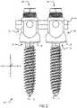
- FIG. 9is side view of a pre-assembled portion of a spinal implant system before being securely coupled to a pair of bone screws.
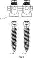
- FIG. 10is side view of the pre-assembled portion of a spinal implant system after being securely coupled to a pair of bone screws.
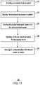
- FIG. 11is a flow chart of an example method of use of disclosed spinal implant embodiments.
- a top loading spinal constructmay include two implant receivers that may support a rod and be connected to a pair of bone screws, respectively.
- the two implant receivers and the rodmay optionally be pre-assembled for rapid installation and/or ease of installation to the pair of bone screws.
- the components of spinal implant system 100can be fabricated from biologically acceptable materials suitable for medical applications, including metals, synthetic polymers, ceramics and bone material and/or their composites.
- the components of spinal implant system 100individually or collectively, can be fabricated from materials such as stainless steel alloys, commercially pure titanium, titanium alloys, Grade 5 titanium, super-elastic titanium alloys, cobalt-chrome alloys, superelastic metallic alloys (e.g., Nitinol, super elasto-plastic metals, such as GUM METAL®), ceramics and composites thereof such as calcium phosphate (e.g., SKELITETM), thermoplastics such as polyaryletherketone (PAEK) including polyetheretherketone (PEEK), polyetherketoneketone (PEKK) and polyetherketone (PEK), carbon-PEEK composites, PEEK-BaSO4 polymeric rubbers, polyethylene terephthalate
- Various components of spinal implant system 100may have material composites, including the above materials, to achieve various desired characteristics such as strength, rigidity, elasticity, compliance, biomechanical performance, durability and radiolucency or imaging preference.
- the components of spinal implant system 100individually or collectively, may also be fabricated from a heterogeneous material such as a combination of two or more of the above-described materials, for example.
- the components of spinal implant system 100may be monolithically formed, integrally connected or include fastening elements and/or instruments, as described herein.
- FIG. 1is a perspective view of a spinal implant system 100 and FIG. 2 is a side view of spinal implant system 100 .
- Spinal implant system 100may include a first implant receiver 20 and a second implant receiver 20 .
- first and second implant receivers 20are the same type of implant receiver. However, in other embodiments, first and second implant receivers 20 may be substantially the same, and or similar to one another.
- First and second implant receivers 20may each include a passageway 22 for receiving a rod 40 , for example.
- first and second implant receivers 20may include first and second set screws 50 , respectively.
- Set screws 50may move upward and downward in the vertical direction, labeled as X direction in FIG. 2 , to secure rod 40 within passageway 22 , for example.
- set screw 50may be a breakoff setscrew having a breakoff portion 52 (see FIG. 2 ), for example.
- set screw 50may be a solid setscrew without a breakoff portion, for example.
- each passageway 22may comprise an aperture extending through the side of implant receiver 20 .
- the passageway 22is closed at the upper end 23 of implant receiver 20 such that the rod 40 is confined within the passageway 22 in two dimensions.
- the solid upper end 23is disposed above the passageway 22 .
- the passageway 22may confine the rod 40 in the vertical direction (labeled as X direction in FIG. 2 ), and in the lateral direction (labeled as Z direction in FIG. 2 ) but still permit some sliding in the horizontal direction (labeled as Y direction in FIG. 2 ).
- a perimeter of the passageway 22is enclosed in the vertical direction and in the lateral direction. For example, as illustrated in FIG.
- the rod 40is confined in the vertical direction and in the lateral direction by passageway 22 but may permit movement in the horizontal direction.
- some embodimentsmay utilize an alternate rod 45 having closed end caps 46 , which may constrain rod 45 from moving too far in the horizontal direction and sliding out of passageway 22 , for example.
- FIG. 3Ais a side view of an implant receiver 20 and FIG. 3B is a top view of a receiver for use with disclosed spinal implant systems 100 .
- implant receiver 20may include a threaded passageway 24 for rotatably supporting and receiving set screw 50 , for example. Threaded passageway 24 may extend in the vertical direction and define a vertical axis A-A of which set screw 50 may move upward and downward in upon rotation of set screw 50 .
- implant receiver 20may include a passageway 22 for receiving rod 40 , for example. Passageway 22 may extend in the horizontal direction and define a horizontal axis B-B, which rod 40 may be coaxially aligned with, for example.
- passageway 22may be shaped like an oval when viewed in a side perspective view as shown in FIG. 3A .
- passageway 22may be shaped like a circle, or a square, for example.
- passageway 22may have a size and shape generally corresponding to a size and shape of rod 40 , for example.
- a side view cross section of rod 40may have an oval like shape generally corresponding to a size and shape of passageway 22 , for example.
- FIG. 4is a side view exploded parts diagram of a spinal implant system 100
- FIG. 5is a perspective view exploded parts diagram of a spinal implant system 100
- set screw 50may have an exterior thread pattern 51 having a timing and/or pitch including a size and shape generally corresponding to the timing and or pitch of threads 25 of threaded passageway 24 for example.
- set screw 50may include a drive end 53 for coupling to a driver (not illustrated) to rotate set screw 50 , for example.
- Drive end 53may take any shape, for example a hexalobular shape, a hexaganol shape, a torx shape, etc.
- an end usermay secure rod 40 within passageway 22 of the first and second implant receivers 20 and securely tighten set screw 50 by rotating set screw 50 at drive end 53 such that set screw 50 advances downward along the vertical axis A-A and secures rod 40 against the lower walls of passageway 22 , for example.
- FIG. 6is a perspective view exploded parts diagram of an implant receiver 20 for use with disclosed spinal implant systems 100 .
- implant receiver 20may include a base portion 21 having a lower cavity configured to securely couple to bone screw 10 and support a crown 2 in a position above the head portion 11 of bone screw 10 , for example.
- Crown 2may include curved support surfaces 3 having a size and shape corresponding to a lower portion of the curved surface of rod 40 , for example. Accordingly, crown 2 may support rod 40 from beneath rod 40 by directly contacting an underside of rod 40 . Additionally, rod 40 may bear down on the lower surface of passageway 22 .
- Spinal implant system 100may further include an upper ring 8 and a lower ring 9 .
- Upper and lower rings 8 , 9may be C-shaped and configured to securely couple head portion 11 of bone screw 10 within lower cavity of base portion 21 , for example. Additional examples of how implant receiver 20 may securely connect to a bone screw 10 via an internal cavity of base portion 21 are also disclosed in detail in each of U.S. Pat. No. 10,335,201, titled Spinal Implant System and Methods of Use; and U.S. Pat. No. 10,653,455 titled Spinal Implant System and Methods of Use; U.S. application Ser. No. 17/167,258, titled Instrument for locking Orthopedic Screws, which are all incorporated herein by reference in their entireties.
- FIG. 7is a side cross section view of spinal implant system 100 .
- the first and second implant receivers 20are securely coupled to uniaxial bone screws 10 .
- a surgeonmay initially couple the first and second implant receivers 20 to respective bone screws 10 by pushing each of implant receivers 20 down against the bone screw 10 by, e.g., an instrument for locking orthopedic screws.
- a surgeonmay push down on each implant receiver 20 simultaneously and in other embodiments a surgeon may push down on each implant receiver 20 in sequence.
- a surgical instrumentmay push implant receiver 20 down such that the upper and lower rings 8 , 9 are seated around the head portion 11 of bone screw 10 and nested within and retained by corresponding cavities 8 a , 9 a of base portion 21 , for example.
- a implant receivers 20may be secured to bone screws 10 .
- first and second bone screws 10may be configured as multi-axial screws, sagittal angulation screws, pedicle screws, mono-axial screws, uni-planar screws, fixed screws, anchors, tissue penetrating screws, conventional screws, expanding screws.
- bone screws 10may be employed with wedges, anchors, buttons, clips, snaps, friction fittings, compressive fittings, expanding rivets, staples, nails, adhesives, posts, connectors, fixation plates and/or a post, to name a few possible example configurations.
- FIG. 8is a perspective view of a rod for use with disclosed spinal implant systems 100 .
- rod 45may be that end caps 46 prevent rod 45 from sliding out of and/or uncoupling from the first and second receivers 20 , for example
- a spinal implant system 100or at least a portion thereof, may be pre-assembled before commencing a surgery.
- rod 40rather than rod 45
- Another advantage of delivering a pre-assembled spinal implant system 100is that a surgeon may relatively quickly secure the pre-assembled spinal implant system 100 to a pair of adjacent vertebrae of a patient, for example.
- FIGS. 9 and 10are side views of a pre-assembled spinal implant 60 .
- a rod 40is secured within the passageways 22 of first and second implant receivers 20 , for example.
- rod 40may be substituted for rod 45 in some embodiments.
- Rod 40may be securely retained within passageways 22 due to first and second set screws 50 pushing down against rod 40 .
- first and second set screw 50may be rotated within threaded passageway 24 such they move downward in the vertical direction and provide a compressive force against rod 40 such that rod 40 is in direct contact with the side portions of passageway 22 and the curved support surfaces 3 of crown 2 , for example.
- the upper portion 50 of spinal construct 100is pre-assembled and the set screws 50 are finger tightened.
- an end usersuch as a surgeon may push down against the first and second implant receivers 20 such that the head portion 11 of each of the bone screws 10 is securely coupled to the corresponding implant receiver 20 , for example.
- FIG. 11is an example flow chart of a method 200 of installation of a pre-assembled spinal implant 60 .
- the following discussion of method 200may include reference to components, features, and functionality of spinal implant system 100 as explained above for context, however, the method as disclosed below is not limited to the specific spinal implant system 100 embodiments disclosed above.
- a spinal implant systemmay be provided, for example an upper portion 50 of spinal implant system 100 or the like.
- a first bone screw 10 or fastener and a second bone screw 10 or fastenermay be secured to a patient's anatomy, for example, a pair of bone screws 10 may be secured to adjacent vertebrae of a patient.
- the pre-assembled spinal implantmay be secured to the first and second bone screws 10 .
- the first and second implant receivers 20are secured to the first and second bone screws 10 by pushing down on the first and second implant receivers 20 .
- each implant receiver 20may be secured to a corresponding bone screw 10 by pushing implant receiver 20 downward and seating various locking rings 8 , 9 around the head portion 11 of bone screw 10 and within various receiving cavities 8 a , 9 a , of implant receiver 20 as explained above.
- the first and second implant receivers 20may be secured to the first and second bone screws simultaneously by, for example, a pair of reduction instruments similar to the rod-reducing instrument described in U.S. Pat. No.
- a rod 40(or rod 45 ) may be secured in a final position by sufficiently tightening the first and second set screws 50 .
- the first and second set screws 50may be rotated by a driver instrument and advanced downward along vertical axis A-A such that they directly contact rod 40 and retain rod 40 in place by a compressive force.
- a breakoff portion of each of the first and second set screws 50may be broken off, for example breakoff portion 52 may be broken off by a break-off instrument such as the instruments disclosed in U.S. application Ser. No. 17/104,897, titled Combination Set Screw Breakoff and Tab Breaker Instrument, for example.
Landscapes
- Health & Medical Sciences (AREA)
- Orthopedic Medicine & Surgery (AREA)
- Life Sciences & Earth Sciences (AREA)
- Surgery (AREA)
- Neurology (AREA)
- Heart & Thoracic Surgery (AREA)
- Engineering & Computer Science (AREA)
- Biomedical Technology (AREA)
- Nuclear Medicine, Radiotherapy & Molecular Imaging (AREA)
- Medical Informatics (AREA)
- Molecular Biology (AREA)
- Animal Behavior & Ethology (AREA)
- General Health & Medical Sciences (AREA)
- Public Health (AREA)
- Veterinary Medicine (AREA)
- Prostheses (AREA)
- Surgical Instruments (AREA)
Abstract
Description
This application incorporates by reference U.S. Pat. No. 10,335,201, titled Spinal Implant System and Methods of Use, filed Jan. 25, 2017; U.S. Pat. No. 10,653,455 titled Spinal Implant System and Methods of Use filed Sep. 12, 2017; U.S. Pat. No. 6,790,209, titled Rod Reducer Instruments and Methods, filed Jul. 1, 2002; U.S. application Ser. No. 17/167,258, titled Instrument for locking Orthopedic Screws, filed Feb. 4, 2021; and U.S. application Ser. No. 17/104,897, titled Combination Set Screw Breakoff and Tab Breaker Instrument, filed Feb. 3, 2021. The entire contents of each are incorporated herein by reference.
The present disclosure generally relates to medical devices for the treatment of musculoskeletal disorders, and more particularly to a spinal implant system and a method for treating a spine.
Spinal pathologies and disorders such as scoliosis, kyphosis, and other curvature abnormalities, degenerative disc disease, disc herniation, osteoporosis, spondylolisthesis, stenosis, tumor and fracture may result from factors including trauma, disease and degenerative conditions caused by injury and aging. Spinal disorders typically result in symptoms including deformity, pain, nerve damage, and partial or complete loss of mobility.
Non-surgical treatments, such as medication, rehabilitation and exercise can be effective, however, may fail to relieve the symptoms associated with these disorders. Surgical treatment of these spinal disorders includes correction, fusion, fixation, discectomy, laminectomy and implantable prosthetics. As part of these surgical treatments, spinal constructs such as vertebral rods are often used to provide stability to a treated region. Rods redirect stresses away from a damaged or defective region while healing takes place to restore proper alignment and generally support the vertebral members. During surgical treatment, one or more rods, spinal constructs, and bone fasteners can be delivered to a surgical site. The rods may be independently attached via a spinal construct and/or a plurality of spinal constructs to the exterior of two or more vertebral members. This disclosure describes an improvement over these prior technologies.
The techniques of this disclosure generally relate to top loading spinal constructs. In various embodiments, a top loading spinal construct may include two implant receivers that may support a rod and be connected to a pair of bone screws, respectively. Some embodiments may optionally be pre-assembled for rapid installation and/or ease of installation.
In one aspect, the present disclosure provides for an implant. The implant may include a rod extending in a lateral direction and a first implant receiver having a first passageway extending through a first sidewall and a second sidewall of the first implant receiver in a lateral direction, for example. In various embodiments, the first implant receiver may have a first threaded passageway extending in a longitudinal direction, for example Additionally, the implant may include a second implant receiver having a second passageway extending through a third sidewall and a fourth sidewall of the second implant receiver in the lateral direction, for example. Furthermore, the second implant receiver may have a second threaded passageway extending in the longitudinal direction, for example. In various embodiments, the implant may include a first set screw having a first outside thread pattern extending along an outside circumferential surface of the first set screw and having a size and shape corresponding to a size and shape of the first threaded passageway, for example. In various embodiments, the implant may include a second set screw having a second outside thread pattern extending along an outside circumferential surface of the second set screw and having a size and shape corresponding to a size and shape of the second threaded passageway, for example. In some embodiments, the rod may extend in the lateral direction through the first and second passageways and may be constrained from moving in the longitudinal direction by the first and second passageways, for example.
In another aspect, the disclosure provides for a method of installing a spinal implant. The method may include the step of providing a pre-assembled implant, that includes a rod extending in a lateral direction and a first implant receiver having a first passageway extending through a first sidewall and a second sidewall of the first implant receiver in the lateral direction, for example. In various embodiments, the first implant receiver may have a first threaded passageway extending in a longitudinal direction and a first base portion for coupling to a first bone screw, for example. In various embodiments, a second implant receiver may have a second passageway extending through a third sidewall and a fourth sidewall of the second implant receiver in the lateral direction, for example. In various embodiments, the second implant receiver may have a second threaded passageway extending in the longitudinal direction and a second base portion for coupling to a second bone screw, for example. In various embodiments, a first set screw having a first outside thread pattern extending along an outside circumferential surface of the first set screw and having a size and shape corresponding to a size and shape of the first threaded passageway may be provided. Additionally, in various embodiments, a second set screw having a second outside thread pattern extending along an outside circumferential surface of the second set screw and having a size and shape corresponding to a size and shape of the second threaded passageway may be provided. In some embodiments, the rod may extend in the lateral direction through the first and second passageways and may be constrained from moving in the longitudinal direction by the first and second passageways, for example. The method may further include the step of securing first and second bone screws to a patient and securing the pre-assembled spinal implant to the first and second bone screws, for example.
The details of one or more aspects of the disclosure are set forth in the accompanying drawings and the description below. Other features, objects, and advantages of the techniques described in this disclosure will be apparent from the description and drawings, and from the claims.
Embodiments of the present disclosure relate generally, for example, to spinal stabilization systems, and more particularly, to top loading spinal constructs. In some embodiments, a top loading spinal construct may include two implant receivers that may support a rod and be connected to a pair of bone screws, respectively. In some embodiments, the two implant receivers and the rod may optionally be pre-assembled for rapid installation and/or ease of installation to the pair of bone screws. Embodiments of the devices and methods are described below with reference to the Figures.
The following discussion omits or only briefly describes certain components, features and functionality related to medical implants, installation tools, and associated surgical techniques, which are apparent to those of ordinary skill in the art. It is noted that various embodiments are described in detail with reference to the drawings, in which like reference numerals represent like parts and assemblies throughout the several views, where possible. Reference to various embodiments does not limit the scope of the claims appended hereto because the embodiments are examples of the inventive concepts described herein. Additionally, any example(s) set forth in this specification are intended to be non-limiting and set forth some of the many possible embodiments applicable to the appended claims. Further, particular features described herein can be used in combination with other described features in each of the various possible combinations and permutations unless the context or other statements clearly indicate otherwise.
Terms such as “same,” “equal,” “planar,” “coplanar,” “parallel,” “perpendicular,” etc. as used herein are intended to encompass a meaning of exactly the same while also including variations that may occur, for example, due to manufacturing processes. The term “substantially” may be used herein to emphasize this meaning, particularly when the described embodiment has the same or nearly the same functionality or characteristic, unless the context or other statements clearly indicate otherwise.
Referring toFIGS. 1-10 generally, variousspinal implant systems 100 are disclosed. The components ofspinal implant system 100 can be fabricated from biologically acceptable materials suitable for medical applications, including metals, synthetic polymers, ceramics and bone material and/or their composites. For example, the components of spinal implant system100, individually or collectively, can be fabricated from materials such as stainless steel alloys, commercially pure titanium, titanium alloys, Grade 5 titanium, super-elastic titanium alloys, cobalt-chrome alloys, superelastic metallic alloys (e.g., Nitinol, super elasto-plastic metals, such as GUM METAL®), ceramics and composites thereof such as calcium phosphate (e.g., SKELITE™), thermoplastics such as polyaryletherketone (PAEK) including polyetheretherketone (PEEK), polyetherketoneketone (PEKK) and polyetherketone (PEK), carbon-PEEK composites, PEEK-BaSO4 polymeric rubbers, polyethylene terephthalate (PET), fabric, silicone, polyurethane, silicone-polyurethane copolymers, polymeric rubbers, polyolefin rubbers, hydrogels, semi-rigid and rigid materials, elastomers, rubbers, thermoplastic elastomers, thermoset elastomers, elastomeric composites, rigid polymers including polyphenylene, polyamide, polyimide, polyetherimide, polyethylene, epoxy, bone material including autograft, allograft, xenograft or transgenic cortical and/or corticocancellous bone, and tissue growth or differentiation factors, partially resorbable materials, such as, for example, composites of metals and calcium-based ceramics, composites of PEEK and calcium based ceramics, composites of PEEK with resorbable polymers, totally resorbable materials, such as, for example, calcium based ceramics such as calcium phosphate, tri-calcium phosphate (TCP), hydroxyapatite (HA)-TCP, calcium sulfate, or other resorbable polymers such as polyaetide, polyglycolide, polytyrosine carbonate, polycaroplaetohe and their combinations.
Various components ofspinal implant system 100 may have material composites, including the above materials, to achieve various desired characteristics such as strength, rigidity, elasticity, compliance, biomechanical performance, durability and radiolucency or imaging preference. The components ofspinal implant system 100, individually or collectively, may also be fabricated from a heterogeneous material such as a combination of two or more of the above-described materials, for example. The components ofspinal implant system 100 may be monolithically formed, integrally connected or include fastening elements and/or instruments, as described herein.
In the example embodiment, eachpassageway 22 may comprise an aperture extending through the side ofimplant receiver 20. In the example embodiment, thepassageway 22 is closed at theupper end 23 ofimplant receiver 20 such that therod 40 is confined within thepassageway 22 in two dimensions. In various embodiments, the solidupper end 23 is disposed above thepassageway 22. For example, in various embodiments, thepassageway 22 may confine therod 40 in the vertical direction (labeled as X direction inFIG. 2 ), and in the lateral direction (labeled as Z direction inFIG. 2 ) but still permit some sliding in the horizontal direction (labeled as Y direction inFIG. 2 ). For example, a perimeter of thepassageway 22 is enclosed in the vertical direction and in the lateral direction. For example, as illustrated inFIG. 2 , therod 40 is confined in the vertical direction and in the lateral direction bypassageway 22 but may permit movement in the horizontal direction. However, as shown inFIG. 8 , some embodiments may utilize analternate rod 45 having closedend caps 46, which may constrainrod 45 from moving too far in the horizontal direction and sliding out ofpassageway 22, for example.
It should be understood that various aspects disclosed herein may be combined in different combinations than the combinations specifically presented in the description and accompanying drawings. For example, features, functionality, and components from one embodiment may be combined with another embodiment and vice versa unless the context clearly indicates otherwise. Similarly, features, functionality, and components may be omitted unless the context clearly indicates otherwise. It should also be understood that, depending on the example, certain acts or events of any of the processes or methods described herein may be performed in a different sequence, may be added, merged, or left out altogether (e.g., all described acts or events may not be necessary to carry out the techniques).
Unless otherwise specifically defined herein, all terms are to be given their broadest possible interpretation including meanings implied from the specification as well as meanings understood by those skilled in the art and/or as defined in dictionaries, treatises, etc. It must also be noted that, as used in the specification and the appended claims, the singular forms “a,” “an” and “the” include plural referents unless otherwise specified, and that the terms “comprises” and/or “comprising,” when used in this specification, specify the presence of stated features, elements, and/or components, but do not preclude the presence or addition of one or more other features, steps, operations, elements, components, and/or groups thereof.
Claims (19)
1. An implant, comprising:
a preassembled combination of a first implant receiver, a second implant receiver, and a rod;
the first implant receiver having a first rod receiving passageway extending through a first sidewall and through a second sidewall of the first implant receiver in a lateral direction, the first implant receiver having a first threaded passageway extending in a longitudinal direction;
the second implant receiver having a second rod receiving passageway extending through a third sidewall and through a fourth sidewall of the second implant receiver in the lateral direction, the second implant receiver having a second threaded passageway extending in the longitudinal direction;
a first set screw having a first outside thread pattern extending along an outside circumferential surface of the first set screw and having a size and shape corresponding to a size and shape of the first threaded passageway; and
a second set screw having a second outside thread pattern extending along an outside circumferential surface of the second set screw and having a size and shape corresponding to a size and shape of the second threaded passageway,
wherein the rod of the preassembled combination extends in the lateral direction through the first and second rod receiving passageways, includes a first endcap and a second endcap, and is constrained from moving in the longitudinal direction by the first and second rod receiving passageways.
2. The implant ofclaim 1 , wherein:
the first implant receiver includes a first base portion for coupling to a first bone screw, and
the second implant receiver includes a second base portion for coupling to a second bone screw.
3. The implant ofclaim 2 , comprising:
a first crown having curved surfaces having a size and shape corresponding to an underside of the rod, the first crown being positioned within the first base portion and above the first bone screw; and
a second crown having curved surfaces having a size and shape corresponding to the underside of the rod, the second crown being positioned within the second base portion and above the first bone screw.
4. The implant ofclaim 3 , wherein at least one of the first base portion and second base portion is configured for mating with a uni-axial bone screw.
5. The implant ofclaim 4 , wherein, in a top down view, the rod extends in the lateral direction such that the rod is oriented directly above the first bone screw and second bone screw.
6. The implant ofclaim 1 , wherein:
a solid first upper surface of the first implant receiver is disposed above the first rod receiving passageway, and
a solid second upper surface of the second implant receiver is disposed above the second rod receiving passageway.
7. The implant ofclaim 1 , wherein a perimeter of the first rod receiving passageway is enclosed, and a perimeter of the second rod receiving passageway is enclosed.
8. The implant ofclaim 1 , wherein the preassembled combination comprises at least the first implant receiver, second implant receiver, first set screw, second set screw, and rod such that the first set screw is disposed in the first threaded passageway and the second set screw is disposed in the second threaded passageway.
9. The implant ofclaim 1 , wherein a size of the first endcap is greater than a size of the first rod receiving passageway and a size of the second endcap is greater than a size of the second rod receiving passageway.
10. The implant ofclaim 1 , wherein, in a cross section view, the rod comprises an oval shape.
11. The implant ofclaim 10 , wherein the first and second rod receiving passageways comprise an opening shaped like an oval, respectively.
12. The implant ofclaim 1 , wherein, in a cross section view, the rod comprises a circular shape.
13. The implant ofclaim 12 , wherein the first and second rod receiving passageways comprise an opening shaped like a circle, respectively.
14. The implant ofclaim 1 , wherein the first and second set screws are break off set screws.
15. A method for installing a spinal implant, comprising:
providing a pre-assembled implant, comprising:
a rod extending in a lateral direction;
a first implant receiver having a first rod receiving passageway extending through a first sidewall and through a second sidewall of the first implant receiver in the lateral direction, the first implant receiver having a first threaded passageway extending in a longitudinal direction and a first base portion for coupling to a first bone screw;
a second implant receiver having a second rod receiving passageway extending through a third sidewall and a fourth sidewall of the second implant receiver in the lateral direction, the second implant receiver having a second threaded passageway extending in the longitudinal direction and a second base portion for coupling to a second bone screw;
a first set screw having a first outside thread pattern extending along an outside circumferential surface of the first set screw and having a size and shape corresponding to a size and shape of the first threaded passageway; and
a second set screw having a second outside thread pattern extending along an outside circumferential surface of the second set screw and having a size and shape corresponding to a size and shape of the second threaded passageway,
wherein the rod extends in the lateral direction through the first and second rod receiving passageways and is constrained from moving in the longitudinal direction by the first and second rod receiving passageways;
securing first and second bone screws to a patient; and
securing the pre-assembled spinal implant to the first and second bone screws.
16. The method ofclaim 15 , further comprising tightening the first and second set screws against the rod such that the rod is secured in place relative to the implant.
17. The method ofclaim 15 , wherein securing the pre-assembled spinal implant to the first and second bone screws further comprises orienting the pre-assembled spinal implant such that, in a top down view, the rod is oriented directly above the first bone screw and second bone screw.
18. The method ofclaim 17 , further comprising:
constraining the rod in the longitudinal direction, and
preventing the rod from sliding out of the first rod receiving passageway and second rod receiving passageway.
19. The method ofclaim 17 , wherein the securing the pre-assembled spinal implant to the first and second bone screws step further comprises simultaneously securing the first implant receiver to the first bone screw and the second implant receiver to the second bone screw.
Priority Applications (3)
| Application Number | Priority Date | Filing Date | Title |
|---|---|---|---|
| US17/318,279US11432848B1 (en) | 2021-05-12 | 2021-05-12 | Top loading quick lock construct |
| EP22164998.1AEP4088675B1 (en) | 2021-05-12 | 2022-03-29 | Top loading quick lock construct |
| CN202210510456.7ACN115337090A (en) | 2021-05-12 | 2022-05-11 | Top loading quick lock construction |
Applications Claiming Priority (1)
| Application Number | Priority Date | Filing Date | Title |
|---|---|---|---|
| US17/318,279US11432848B1 (en) | 2021-05-12 | 2021-05-12 | Top loading quick lock construct |
Publications (1)
| Publication Number | Publication Date |
|---|---|
| US11432848B1true US11432848B1 (en) | 2022-09-06 |
Family
ID=80979052
Family Applications (1)
| Application Number | Title | Priority Date | Filing Date |
|---|---|---|---|
| US17/318,279ActiveUS11432848B1 (en) | 2021-05-12 | 2021-05-12 | Top loading quick lock construct |
Country Status (3)
| Country | Link |
|---|---|
| US (1) | US11432848B1 (en) |
| EP (1) | EP4088675B1 (en) |
| CN (1) | CN115337090A (en) |
Cited By (1)
| Publication number | Priority date | Publication date | Assignee | Title |
|---|---|---|---|---|
| US20240074797A1 (en)* | 2021-12-01 | 2024-03-07 | Matthew Amarante | Capped Distraction/Compression Rod System |
Citations (211)
| Publication number | Priority date | Publication date | Assignee | Title |
|---|---|---|---|---|
| US3604487A (en) | 1969-03-10 | 1971-09-14 | Richard S Gilbert | Orthopedic screw driving means |
| US3844291A (en) | 1973-04-26 | 1974-10-29 | G Moen | Grip device |
| US4411259A (en) | 1980-02-04 | 1983-10-25 | Drummond Denis S | Apparatus for engaging a hook assembly to a spinal column |
| US5020519A (en) | 1990-12-07 | 1991-06-04 | Zimmer, Inc. | Sagittal approximator |
| US5113685A (en) | 1991-01-28 | 1992-05-19 | Acromed Corporation | Apparatus for contouring spine plates and/or rods |
| US5207678A (en) | 1989-07-20 | 1993-05-04 | Prufer | Pedicle screw and receiver member therefore |
| US5314431A (en) | 1992-06-19 | 1994-05-24 | Graziano Thomas A | Surgical instrument used in conjunction with fixation of fractures or surgical osteotomies |
| US5330472A (en) | 1990-06-13 | 1994-07-19 | Howmedica Gmbh | Device for applying a tensional force between vertebrae of the human vertebral column |
| US5364397A (en) | 1993-06-01 | 1994-11-15 | Zimmer, Inc. | Spinal coupler seater with dual jaws and an independent plunger |
| US5389099A (en) | 1993-07-28 | 1995-02-14 | Hartmeister; Ruben | Keyhole rod bender |
| US5449361A (en) | 1993-04-21 | 1995-09-12 | Amei Technologies Inc. | Orthopedic cable tensioner |
| US5458608A (en) | 1993-06-03 | 1995-10-17 | Surgin Surgical Instrumentation Inc. | Laparoscopic instruments and methods |
| US5466243A (en) | 1994-02-17 | 1995-11-14 | Arthrex, Inc. | Method and apparatus for installing a suture anchor through a hollow cannulated grasper |
| US5575792A (en) | 1995-07-14 | 1996-11-19 | Fastenetix, L.L.C. | Extending hook and polyaxial coupling element device for use with top loading rod fixation devices |
| US5609593A (en) | 1995-07-13 | 1997-03-11 | Fastenetix, Llc | Advanced polyaxial locking hook and coupling element device for use with top loading rod fixation devices |
| US5609654A (en) | 1992-06-02 | 1997-03-11 | Mobil Oil Corporation | Process for hydroisomerization and etherification of isoalkenes |
| US5616143A (en) | 1995-02-06 | 1997-04-01 | Schlapfer; Johannes F. | Surgical forceps |
| US5630817A (en) | 1992-11-18 | 1997-05-20 | Eurosurgical | Rod attachment device for rachidian orthopaedy |
| US5643263A (en) | 1995-08-14 | 1997-07-01 | Simonson; Peter Melott | Spinal implant connection assembly |
| US5683391A (en) | 1995-06-07 | 1997-11-04 | Danek Medical, Inc. | Anterior spinal instrumentation and method for implantation and revision |
| US5720751A (en) | 1996-11-27 | 1998-02-24 | Jackson; Roger P. | Tools for use in seating spinal rods in open ended implants |
| US5782830A (en) | 1995-10-16 | 1998-07-21 | Sdgi Holdings, Inc. | Implant insertion device |
| US5797911A (en) | 1996-09-24 | 1998-08-25 | Sdgi Holdings, Inc. | Multi-axial bone screw assembly |
| US5899901A (en) | 1991-05-18 | 1999-05-04 | Middleton; Jeffrey Keith | Spinal fixation system |
| US5910141A (en) | 1997-02-12 | 1999-06-08 | Sdgi Holdings, Inc. | Rod introduction apparatus |
| US5944720A (en) | 1998-03-25 | 1999-08-31 | Lipton; Glenn E | Posterior spinal fixation system |
| US5947967A (en) | 1997-10-22 | 1999-09-07 | Sdgt Holdings, Inc. | Variable angle connector |
| US6036692A (en) | 1997-02-12 | 2000-03-14 | Sdgi Holdings, Inc. | Rod introducer forceps |
| US6042582A (en) | 1997-05-20 | 2000-03-28 | Ray; Charles D. | Instrumentation and method for facilitating insertion of spinal implant |
| US6063088A (en) | 1997-03-24 | 2000-05-16 | United States Surgical Corporation | Method and instrumentation for implant insertion |
| US6074391A (en) | 1997-06-16 | 2000-06-13 | Howmedica Gmbh | Receiving part for a retaining component of a vertebral column implant |
| US6110172A (en)* | 1998-07-31 | 2000-08-29 | Jackson; Roger P. | Closure system for open ended osteosynthesis apparatus |
| US6224596B1 (en)* | 1997-01-06 | 2001-05-01 | Roger P. Jackson | Set screw for use with osteosynthesis apparatus |
| US6280442B1 (en) | 1999-09-01 | 2001-08-28 | Sdgi Holdings, Inc. | Multi-axial bone screw assembly |
| US6415693B1 (en) | 2000-08-12 | 2002-07-09 | Stryker Trauma Gmbh | Sleeve-shaped device to retain screws while these are turned into an object such as a bone by means of a screw driver |
| US6440133B1 (en) | 2001-07-03 | 2002-08-27 | Sdgi Holdings, Inc. | Rod reducer instruments and methods |
| US20020169453A1 (en) | 1998-08-07 | 2002-11-14 | Berger J. Lee | Cannulated internally threaded bone screw |
| US20020166421A1 (en) | 2001-05-11 | 2002-11-14 | Bowerman Jeffrey Allen | Screw driving, locking and alignment device |
| US6497166B1 (en) | 2000-11-07 | 2002-12-24 | Mark Fleckenstein | Screw setter tool |
| US6520962B1 (en) | 2000-10-23 | 2003-02-18 | Sdgi Holdings, Inc. | Taper-locked adjustable connector |
| US6562038B1 (en) | 2000-03-15 | 2003-05-13 | Sdgi Holdings, Inc. | Spinal implant connection assembly |
| US6572618B1 (en) | 2000-03-15 | 2003-06-03 | Sdgi Holdings, Inc. | Spinal implant connection assembly |
| US6579292B2 (en) | 2001-06-18 | 2003-06-17 | Sdgi Holdings, Inc. | Connection assembly for spinal implant systems |
| US6648887B2 (en) | 2002-01-23 | 2003-11-18 | Richard B. Ashman | Variable angle spinal implant connection assembly |
| US6685705B1 (en) | 2000-10-23 | 2004-02-03 | Sdgi Holdings, Inc. | Six-axis and seven-axis adjustable connector |
| US6755830B2 (en) | 2001-07-04 | 2004-06-29 | Sofamor S.N.C. | Connector for a spinal fixation member |
| US6857343B1 (en) | 2003-09-30 | 2005-02-22 | Codman & Shurtleff, Inc. | Spring-loaded threaded fastener holder |
| US6872209B2 (en) | 2000-03-15 | 2005-03-29 | Sdgi Holdings, Inc. | Spinal implant connection assembly |
| US20050159750A1 (en) | 2003-12-30 | 2005-07-21 | Thomas Doherty | Bone anchor assemblies and methods of manufacturing bone anchor assemblies |
| US20050203519A1 (en)* | 2004-03-09 | 2005-09-15 | Jurgen Harms | Rod-like element for application in spinal or trauma surgery, and stabilization device with such a rod-like element |
| US6945933B2 (en) | 2002-06-26 | 2005-09-20 | Sdgi Holdings, Inc. | Instruments and methods for minimally invasive tissue retraction and surgery |
| US20050273101A1 (en) | 2004-05-28 | 2005-12-08 | Aesculap Ag & Co. Kg | Bone screw and osteosynthesis device |
| US20060041261A1 (en) | 2004-08-17 | 2006-02-23 | Osypka Thomas P | Apparatus and method for attaching connective tissue to bone |
| US20060052785A1 (en)* | 2004-08-18 | 2006-03-09 | Augostino Teena M | Adjacent level facet arthroplasty devices, spine stabilization systems, and methods |
| US20060241593A1 (en) | 2005-04-08 | 2006-10-26 | Sdgi Holdings, Inc. | Multi-piece vertebral attachment device |
| US20060241600A1 (en) | 2005-03-23 | 2006-10-26 | Ensign Michael D | Percutaneous pedicle screw assembly |
| US20070010816A1 (en) | 2005-06-29 | 2007-01-11 | Wilkinson Trent R | Tool driver, coupler and associated method |
| US20070122764A1 (en) | 2005-11-28 | 2007-05-31 | Ace Surgical Supply Co., Inc. | Orthodontic bone screw |
| US7226453B2 (en) | 2004-03-31 | 2007-06-05 | Depuy Spine, Inc. | Instrument for inserting, adjusting and removing pedicle screws and other orthopedic implants |
| US20080015596A1 (en) | 2006-04-28 | 2008-01-17 | Whipple Dale E | Large diameter multiple piece bone anchor assembly |
| US20080041196A1 (en) | 2006-08-16 | 2008-02-21 | Warsaw Orthopedic Inc. | Surgical Screw Insertion Devices and Methods of Use |
| US20080071274A1 (en) | 2006-09-15 | 2008-03-20 | Ensign Michael D | Percutaneous Screw Assembly and Placement Method |
| US20080147126A1 (en) | 2001-10-18 | 2008-06-19 | Fxdevices, Llc | System and method for a cap used in the fixation of bone fractures |
| US20080147128A1 (en) | 2006-12-15 | 2008-06-19 | Zimmer Technology, Inc. | Cannulated bone screw and cannulated driver for the implantation thereof |
| US20080154373A1 (en)* | 2006-12-21 | 2008-06-26 | Warsaw Orthopedic, Inc. | Curable orthopedic implant devices configured to be hardened after placement in vivo |
| US20080200918A1 (en) | 2007-02-12 | 2008-08-21 | James Spitler | Pedicle screw driver |
| US20080269768A1 (en) | 2007-04-10 | 2008-10-30 | Stryker Trauma Sa | Bone screw holding device |
| US20090005787A1 (en) | 2007-06-28 | 2009-01-01 | Angela Crall | Device and system for implanting polyaxial bone fasteners |
| US7572264B2 (en) | 2005-06-28 | 2009-08-11 | Warsaw Orthopedic, Inc. | Driver instrument for use in a surgical application |
| US20090264895A1 (en) | 2008-04-22 | 2009-10-22 | Warsaw Orthopedic, Inc. | Systems and methods for implanting a bone fastener and delivering a bone filling material |
| US20100010543A1 (en)* | 2007-05-01 | 2010-01-14 | Jackson Roger P | Dynamic stabilization connecting member with floating core, compression spacer and over-mold |
| US20100063546A1 (en)* | 2008-09-09 | 2010-03-11 | Warsaw Orthopedic, Inc. | Offset vertebral rod connector |
| US7771459B2 (en) | 2004-06-07 | 2010-08-10 | Degima Gmbh | Fastener having torque optimized head |
| US20100249798A1 (en) | 2007-11-05 | 2010-09-30 | Denys Sournac | instrument for placing a bone screw, notably a so called "polyaxial" screw of vertebral osteosynthesis equipment |
| US20100249846A1 (en) | 2009-03-25 | 2010-09-30 | Simonson Peter M | Variable height, multi-axial bone screw assembly |
| US7846167B2 (en) | 2005-11-07 | 2010-12-07 | Biomet Microfixation, Llc | Driver assembly and fastener apparatus |
| US20110077693A1 (en) | 2009-09-25 | 2011-03-31 | Warsaw Orthopedic, Inc. | Tool and component egaging mechanism |
| US7947047B2 (en) | 2005-06-20 | 2011-05-24 | Ams Research Corporation | Medical screwdrivers and methods |
| US20110160775A1 (en) | 2006-05-30 | 2011-06-30 | Warsaw Orthopedic, Inc. | Locking Device And Method Employing A Posted Member To Control Positioning Of A Stabilization Member Of A Bone Stabilization System |
| US7976463B2 (en) | 2002-06-26 | 2011-07-12 | Warsaw Orthopedic, Inc. | Instruments and methods for minimally invasive tissue retraction and surgery |
| US7988699B2 (en) | 2004-10-19 | 2011-08-02 | Warsaw Orthopedic, Inc. | Adjustable instrumentation for spinal implant insertion |
| US8048124B2 (en) | 2005-05-04 | 2011-11-01 | Spinefrontier Inc | Spinal screw assembly and screw insertion tool |
| US20110270322A1 (en) | 2010-05-03 | 2011-11-03 | Olsen Russell G | Surgical fastener and associated systems and methods |
| US20110270321A1 (en) | 2010-04-30 | 2011-11-03 | Warsaw Orthopedic, Inc. | Engaging Member With a Cavity-Base for Engaging a Connecting Element to a Bone Anchor |
| US20110282398A1 (en) | 2010-05-13 | 2011-11-17 | Tom Overes | Bone Screw Assembly and Instruments for Implantation of the Same |
| US20110301650A1 (en) | 2005-10-18 | 2011-12-08 | Warsaw Orthopedic, Inc. | Adjsutable bone anchor asembly |
| US8100916B2 (en) | 2005-07-21 | 2012-01-24 | Depuy Spine, Inc. | Instrument for inserting, adjusting and removing a surgical implant |
| US20120046700A1 (en)* | 2009-06-15 | 2012-02-23 | Jackson Roger P | Polyaxial bone anchor with pop-on shank and pivotable retainer |
| US20120123481A1 (en) | 2010-11-15 | 2012-05-17 | Lin Chih I | Bone fixation device |
| US8221431B2 (en) | 2006-12-18 | 2012-07-17 | Greatbatch Medical S.A. | Calibrated mechanical orthopedic driver with wear-compensated torque-limiting mechanism |
| US8231635B2 (en) | 2007-01-18 | 2012-07-31 | Stryker Spine | Polyaxial screwdriver for a pedicle screw system |
| US20120203288A1 (en) | 2009-10-05 | 2012-08-09 | Robert Lange | Spinal fixation system and screwdriver tool for use with the same |
| US20120215263A1 (en) | 2011-02-23 | 2012-08-23 | Choon Sung Lee | Extensible pedicle screw coupling device |
| US8262670B2 (en) | 2009-10-28 | 2012-09-11 | Aesculap Implant Systems, Llc | Self-retaining surgical driver |
| US20120239095A1 (en) | 2011-03-14 | 2012-09-20 | Synthes Usa, Llc | Driver device with anti-rotation feature |
| US20120253398A1 (en) | 2011-03-30 | 2012-10-04 | Warsaw Orthopedic, Inc. | Sacroiliac terminal anchor device and method |
| US20120277798A1 (en)* | 2011-04-28 | 2012-11-01 | Warsaw Orthopedic, Inc. | Spinal Rod Construct to Limit Facet Impingement |
| US8343165B2 (en) | 2005-09-26 | 2013-01-01 | Pioneer Surgical Technology, Inc. | Apparatus and method for implantation of surgical devices |
| US8394108B2 (en) | 2010-06-18 | 2013-03-12 | Spine Wave, Inc. | Screw driver for a multiaxial bone screw |
| US20130072986A1 (en) | 2011-09-21 | 2013-03-21 | James C. Robinson | Fenestrated bone screws and methods of bone fastening and stabilization |
| US8459155B2 (en) | 2010-09-03 | 2013-06-11 | Smith & Nephew, Inc. | Modified fastener and insertion tool |
| US8460307B2 (en) | 2006-08-17 | 2013-06-11 | Synthes Usa, Llc | Push-off driver and method for inserting bone screws |
| US8540756B2 (en) | 2010-05-03 | 2013-09-24 | Ortho Vation Medical Llc | Surgical fastener and associated systems and methods |
| US20130261671A1 (en) | 2010-12-10 | 2013-10-03 | Celgen Ag | Device for bone regeneration and bone distraction |
| US8585741B2 (en) | 2007-07-19 | 2013-11-19 | DePuy Synthes Products, LLC | Clamps used for interconnecting a bone anchor to a rod |
| US20140018816A1 (en) | 2012-07-12 | 2014-01-16 | Synthes Usa, Llc | Torque transmitting ball joint driver having a rigid fixation mechanism |
| US20140066945A1 (en) | 2012-08-31 | 2014-03-06 | Warsaw Orthopedic, Inc. | Surgical implant system and method |
| US20140142639A1 (en) | 2012-11-16 | 2014-05-22 | Synthes Usa, Llc | Locking and lagging bone screws |
| US8747411B2 (en) | 2009-09-30 | 2014-06-10 | Michael David Mitchell | Fluid delivery and bone screw driver apparatus |
| US20140172027A1 (en) | 2012-12-05 | 2014-06-19 | Biedermann Technologies Gmbh & Co. Kg | Dynamic bone anchor and method of manufacturing the same |
| US8757035B2 (en) | 2011-12-20 | 2014-06-24 | Symmetry Medical, Inc. | Torque limiting ratchet device |
| US8763499B2 (en) | 2010-06-04 | 2014-07-01 | The University Of North Carolina At Chapel Hill | Screw holder-driver apparatuses, systems and methods |
| US8784431B1 (en) | 2012-06-11 | 2014-07-22 | Choice Spine, Lp | Medical screwdriver |
| US8806973B2 (en) | 2009-12-02 | 2014-08-19 | Covidien Lp | Adapters for use between surgical handle assembly and surgical end effector |
| US20140257411A1 (en) | 2013-03-08 | 2014-09-11 | Warsaw Orthopedic, Inc. | Bone fastener and methods of use |
| US20140288567A1 (en) | 2013-03-15 | 2014-09-25 | Royal Oak Industries | Pedicle screw driver |
| US8845652B2 (en) | 2007-02-27 | 2014-09-30 | Warsaw Orthopedic, Inc. | Surgical driver |
| US20140324062A1 (en) | 2013-04-29 | 2014-10-30 | Silony Medical International AG | Screwdriver for bone screws |
| US8882775B2 (en) | 2011-04-15 | 2014-11-11 | DePuy Synthes Products, LLC | Fixation assembly |
| US8900248B2 (en) | 2008-06-13 | 2014-12-02 | The University Of Toledo | Insertion assembly for minimally invasive spinal surgery |
| US8900280B2 (en) | 2011-06-09 | 2014-12-02 | Christel Paroth | Surgical instrument |
| US8932303B2 (en) | 2012-04-23 | 2015-01-13 | Alphatec Spine Inc | Surgical screwdriver |
| US8945193B2 (en) | 2010-07-20 | 2015-02-03 | X-Spine Systems, Inc. | Minimally invasive spinal facet compression screw and system for bone joint fusion and fixation |
| US20150039034A1 (en)* | 2013-08-01 | 2015-02-05 | Musc Foundation For Research Development | Skeletal bone fixation mechanism |
| US8968276B2 (en) | 2007-09-21 | 2015-03-03 | Covidien Lp | Hand held surgical handle assembly, surgical adapters for use between surgical handle assembly and surgical end effectors, and methods of use |
| US8986349B1 (en)* | 2009-11-11 | 2015-03-24 | Nuvasive, Inc. | Systems and methods for correcting spinal deformities |
| US8992575B1 (en) | 2012-06-22 | 2015-03-31 | Seaspine, Inc. | Spinal implants having offsets and hooks |
| US8992587B2 (en) | 2010-07-20 | 2015-03-31 | X-Spine Systems, Inc. | Spinal facet compression screw with variable pitch thread zones and buttress head |
| US9017333B2 (en) | 2008-04-17 | 2015-04-28 | Warsaw Orthopedic, Inc. | Surgical tool |
| US9055943B2 (en) | 2007-09-21 | 2015-06-16 | Covidien Lp | Hand held surgical handle assembly, surgical adapters for use between surgical handle assembly and surgical end effectors, and methods of use |
| US20150201987A1 (en) | 2014-01-20 | 2015-07-23 | Zimmer Spine, Inc. | Quick-lock driver for a bone screw |
| US20150201972A1 (en) | 2013-07-18 | 2015-07-23 | Ortho Innovations, Llc | Spring clip bottom loading polyaxial ball and socket fastener |
| US9089371B1 (en) | 2014-09-19 | 2015-07-28 | Globus Medical Inc. | Orthopedic stabilization devices and methods for installation thereof |
| US9113976B2 (en) | 2001-12-04 | 2015-08-25 | DePuy Synthes Products, Inc. | Headless compression screw with integrated reduction-compression instrument |
| US20150250521A1 (en) | 2012-10-18 | 2015-09-10 | Deroyal Industries Inc. | Driver Apparatus For A Pedicle Screw Assembly |
| US9149307B2 (en) | 2010-01-15 | 2015-10-06 | Pioneer Surgical Technology, Inc. | Low friction rod persuader |
| US20150359575A1 (en) | 2013-01-15 | 2015-12-17 | Zimmer Gmbh | Surgical bone screw and implant system |
| US9216044B2 (en) | 2011-10-07 | 2015-12-22 | Regents Of The University Of Minnesota | Stripped pedicle screw driver bit |
| US20150374417A1 (en) | 2013-02-05 | 2015-12-31 | Safe Orthopaedics | Implantation assembly comprising a drive instrument pre-fitted on a bone implant |
| US9295500B2 (en) | 2013-06-12 | 2016-03-29 | Spine Wave, Inc. | Screw driver with release for a multiaxial bone screw |
| US9314274B2 (en) | 2011-05-27 | 2016-04-19 | DePuy Synthes Products, Inc. | Minimally invasive spinal fixation system including vertebral alignment features |
| US9387025B2 (en) | 2012-04-04 | 2016-07-12 | Smith & Nephew, Inc. | Bone screw and self-retaining driver |
| US9402663B2 (en) | 2010-04-23 | 2016-08-02 | DePuy Synthes Products, Inc. | Minimally invasive instrument set, devices and related methods |
| US9446507B2 (en) | 2013-03-12 | 2016-09-20 | Eca Medical Instruments | Ratcheting torque wrench |
| US20160278815A1 (en) | 2013-03-18 | 2016-09-29 | Fitzbionics Limited | Spinal Implant Assembly |
| US20160317206A1 (en) | 2015-04-30 | 2016-11-03 | Warsaw Orthopedic, Inc. | Spinal implant system and methods of use |
| US9526553B2 (en) | 2014-04-04 | 2016-12-27 | K2M, Inc. | Screw insertion instrument |
| US9572605B2 (en) | 2012-10-09 | 2017-02-21 | Warsaw Orthopedic, Inc. | Surgical instrument and method |
| US9597135B1 (en) | 2011-09-25 | 2017-03-21 | Nexxt Spine, LLC | Bone screw inserter |
| US20170119537A1 (en) | 2015-05-13 | 2017-05-04 | Gil Tepper | Three column spinal fixation implants and associated surgical methods |
| US9642654B2 (en) | 2014-06-16 | 2017-05-09 | Alphatec Spine, Inc. | Single action locking pedicle screwdriver |
| US9687285B2 (en) | 2012-01-25 | 2017-06-27 | Spectrum Spine Ip Holdings, Llc | Fenestrated bone screws and methods of bone fastening and stabilization |
| US9724149B2 (en) | 2013-03-07 | 2017-08-08 | Warsaw Orhtopedic, Inc. | Surgical implant system and method |
| US20170245898A1 (en) | 2016-02-26 | 2017-08-31 | Warsaw Orthopedic, Inc | Spinal implant system and methods of use |
| US9808354B2 (en) | 2014-01-17 | 2017-11-07 | Stryker European Holdings I, Llc | Implant insertion tool |
| US9855087B2 (en) | 2014-08-04 | 2018-01-02 | DePuy Synthes Products, LLC | Methods and devices for spinal screw insertion |
| US20180049777A1 (en) | 2016-08-17 | 2018-02-22 | Warsaw Orthopedic, Inc | Spinal construct and method |
| US20180071000A1 (en) | 2016-09-13 | 2018-03-15 | Arthrex, Inc. | Telescoping fixation devices and methods of use |
| US9949731B2 (en) | 2015-10-07 | 2018-04-24 | Medos International Sàrl | Systems and methods for manipulating bone |
| US20180110548A1 (en) | 2016-10-26 | 2018-04-26 | Warsaw Orthopedic, Inc | Spinal construct |
| US9956003B2 (en) | 2015-09-18 | 2018-05-01 | Warsaw Orthopedic, Inc | Spinal implant system and methods of use |
| US9968384B2 (en) | 2014-07-01 | 2018-05-15 | Aesculap Ag | Medical screw driver, shank for medical screw driver and method of introducing pedicle screws |
| US20180146990A1 (en) | 2016-11-29 | 2018-05-31 | MIS IP I Holdings LLC | Apparatus and method for accessing the spine and placing pedicle screws without the use of guide-wires |
| US9987066B2 (en) | 2014-12-15 | 2018-06-05 | Medos International Sarl | Bone anchor driver and methods |
| US20180153600A1 (en) | 2016-12-06 | 2018-06-07 | Medos International Sarl | Longitudinally-adjustable bone anchors and related methods |
| US20180193063A1 (en) | 2017-01-12 | 2018-07-12 | Warsaw Orthopedic, Inc | Spinal implant system and methods of use |
| US20180193062A1 (en) | 2017-01-11 | 2018-07-12 | Warsaw Orthopedic, Inc | Spinal implant system and methods of use |
| US20180206890A1 (en) | 2017-01-25 | 2018-07-26 | Warsaw Orthopedic, Inc | Spinal implant system and methods of use |
| US10045787B2 (en) | 2014-10-13 | 2018-08-14 | Zimmer, Inc. | Orthopedic device holder system |
| US20180235684A1 (en) | 2016-10-26 | 2018-08-23 | Nexus Spine, LLC | Self-Retaining Screwdriver |
| US10076374B2 (en) | 2014-10-23 | 2018-09-18 | Medos International Sárl | Biceps tenodesis delivery tools |
| US10105165B2 (en) | 2014-03-14 | 2018-10-23 | Biedermann Technologies Gmbh & Co. Kg | Instrument for holding and inserting a bone anchor |
| US20180353224A1 (en) | 2017-06-12 | 2018-12-13 | K2M, Inc. | Screw insertion instrument and methods of use |
| US10160105B2 (en) | 2014-04-01 | 2018-12-25 | Eca Medical Instruments | Fortified high torque device |
| US10219854B2 (en) | 2014-04-01 | 2019-03-05 | Eca Medical Instruments | Modular clutch assembly |
| US20190076170A1 (en) | 2017-09-12 | 2019-03-14 | Warsaw Orthopedic, Inc | Spinal implant system and methods of use |
| US10274021B2 (en) | 2015-04-17 | 2019-04-30 | Viant As&O Holding, Llc | Two stage torque limiter |
| US10285740B2 (en) | 2015-03-11 | 2019-05-14 | Warsaw Orthpedic, Inc. | Surgical instrument and method |
| US20190159820A1 (en) | 2016-08-24 | 2019-05-30 | Wyatt Drake Geist | Length adjustable modular screw system |
| US20190183535A1 (en)* | 2017-12-15 | 2019-06-20 | Warsaw Orthopedic, Inc. | Spinal implant system and methods of use |
| US10349986B2 (en) | 2017-04-20 | 2019-07-16 | Warsaw Orthopedic, Inc. | Spinal implant system and method |
| US10363073B2 (en) | 2016-07-13 | 2019-07-30 | Medos International Sàrl | Bone anchor assemblies and related instrumentation |
| US20190254730A1 (en) | 2018-02-19 | 2019-08-22 | Warsaw Orthopedic, Inc. | Surgical instrument and method |
| US20190254729A1 (en) | 2018-02-19 | 2019-08-22 | Warsaw Orthopedic, Inc. | Surgical instrument and method |
| US10390967B2 (en) | 2016-08-19 | 2019-08-27 | DePuy Synthes Products, Inc. | Inserter guide and driver system |
| US10426535B2 (en) | 2017-01-05 | 2019-10-01 | Stryker European Holdings I, Llc | Self-holding screw head |
| US10433883B2 (en) | 2017-06-27 | 2019-10-08 | Medos International Sarl | Spinal screw insertion devices and methods |
| US10448978B2 (en) | 2017-07-27 | 2019-10-22 | Warsaw Orthopedic, Inc. | Spinal implant system and method |
| US20190329388A1 (en) | 2018-04-27 | 2019-10-31 | Imds Llc | Fastener retention mechanisms |
| US10463404B2 (en) | 2017-07-27 | 2019-11-05 | Warsaw Orthopedic, Inc. | Spinal implant system and method |
| US10470805B2 (en) | 2016-08-24 | 2019-11-12 | Biedermann Technologies Gmbh & Co. Kg | Instrument for locking and unlocking a head of a bone anchor in a polyaxial bone anchoring device |
| US20200030015A1 (en) | 2018-07-27 | 2020-01-30 | Warsaw Orthopedic, Inc. | Spinal implant system and method |
| US20200038064A1 (en) | 2018-07-31 | 2020-02-06 | GetSet Surgical SA | Spinal surgery systems and methods |
| US10582925B2 (en) | 2017-02-06 | 2020-03-10 | Medos International Sarl | Devices, systems, and methods for knotless suture anchors |
| US10603078B2 (en) | 2016-10-26 | 2020-03-31 | Warsaw Orthopedic, Inc. | Surgical instrument and method |
| US20200121397A1 (en) | 2018-10-18 | 2020-04-23 | Warsaw Orthopedic, Inc. | Spinal implant system and method |
| US20200121398A1 (en) | 2018-10-18 | 2020-04-23 | Warsaw Orthopedic, Inc. | Spinal implant system and method |
| US10646261B2 (en) | 2018-07-24 | 2020-05-12 | Warsaw Orthopedic, Inc. | Multi-purpose screwdriver and method of use |
| US10653457B2 (en) | 2017-02-01 | 2020-05-19 | Medos International Sarl | Multi-function driver instruments and related methods |
| US10660687B2 (en) | 2017-06-30 | 2020-05-26 | A&E Advanced Closure Systems, Llc | Driver tool and method |
| US10702315B2 (en) | 2016-05-09 | 2020-07-07 | Aesculap Ag | Medical instrument for provisionally fastening a polyaxial pedicle screw |
| US10702316B2 (en) | 2015-11-26 | 2020-07-07 | Silony Medical International AG | Handling instrument for a bone screw |
| US10729419B2 (en) | 2014-10-23 | 2020-08-04 | Medos International Sarl | Biceps tenodesis implants and delivery tools |
| US10751092B2 (en) | 2011-09-30 | 2020-08-25 | Biedermann Technologies Gmbh & Co. Kg | Bone anchoring device and tool cooperating with such a bone anchoring device |
| US10779872B2 (en) | 2017-11-02 | 2020-09-22 | Medos International Sarl | Bone anchor insertion instruments and methods |
| US20200340558A1 (en) | 2019-04-24 | 2020-10-29 | Nuvasive, Inc. | Transmission assembly |
| US20200375638A1 (en) | 2019-05-29 | 2020-12-03 | Spine Wave, Inc. | Modular spinal screw yoke inserter |
| US20200390486A1 (en) | 2019-06-13 | 2020-12-17 | Medos International Sarl | Screw inserter instruments and methods |
| US20200390478A1 (en) | 2019-06-13 | 2020-12-17 | Medos International Sarl | Screw inserter instruments and methods |
| US10869751B2 (en) | 2014-10-23 | 2020-12-22 | Medos International Sarl | Biceps tenodesis implants and delivery tools |
| US10874448B2 (en) | 2015-11-11 | 2020-12-29 | Lunar Innovation Limited | Tool for use with a fastener |
Family Cites Families (5)
| Publication number | Priority date | Publication date | Assignee | Title |
|---|---|---|---|---|
| US7473267B2 (en)* | 2003-04-25 | 2009-01-06 | Warsaw Orthopedic, Inc. | System and method for minimally invasive posterior fixation |
| US20090088799A1 (en)* | 2007-10-01 | 2009-04-02 | Chung-Chun Yeh | Spinal fixation device having a flexible cable and jointed components received thereon |
| US8523915B2 (en)* | 2010-12-09 | 2013-09-03 | Warsaw Orthopedic, Inc. | Friction set screw for use with spinal implant systems |
| WO2018209186A1 (en)* | 2017-05-11 | 2018-11-15 | Marc Evan Richelsoph | Advanced polyaxial system and surgical procedure |
| US11298170B2 (en)* | 2019-05-17 | 2022-04-12 | Warsaw Orthopedic, Inc. | Spinal implant system and methods of use |
- 2021
- 2021-05-12USUS17/318,279patent/US11432848B1/enactiveActive
- 2022
- 2022-03-29EPEP22164998.1Apatent/EP4088675B1/enactiveActive
- 2022-05-11CNCN202210510456.7Apatent/CN115337090A/enactivePending
Patent Citations (244)
| Publication number | Priority date | Publication date | Assignee | Title |
|---|---|---|---|---|
| US3604487A (en) | 1969-03-10 | 1971-09-14 | Richard S Gilbert | Orthopedic screw driving means |
| US3844291A (en) | 1973-04-26 | 1974-10-29 | G Moen | Grip device |
| US4411259A (en) | 1980-02-04 | 1983-10-25 | Drummond Denis S | Apparatus for engaging a hook assembly to a spinal column |
| US5207678A (en) | 1989-07-20 | 1993-05-04 | Prufer | Pedicle screw and receiver member therefore |
| US5330472A (en) | 1990-06-13 | 1994-07-19 | Howmedica Gmbh | Device for applying a tensional force between vertebrae of the human vertebral column |
| US5020519A (en) | 1990-12-07 | 1991-06-04 | Zimmer, Inc. | Sagittal approximator |
| US5113685A (en) | 1991-01-28 | 1992-05-19 | Acromed Corporation | Apparatus for contouring spine plates and/or rods |
| US5899901A (en) | 1991-05-18 | 1999-05-04 | Middleton; Jeffrey Keith | Spinal fixation system |
| US5609654A (en) | 1992-06-02 | 1997-03-11 | Mobil Oil Corporation | Process for hydroisomerization and etherification of isoalkenes |
| US5314431A (en) | 1992-06-19 | 1994-05-24 | Graziano Thomas A | Surgical instrument used in conjunction with fixation of fractures or surgical osteotomies |
| US5630817A (en) | 1992-11-18 | 1997-05-20 | Eurosurgical | Rod attachment device for rachidian orthopaedy |
| US5449361A (en) | 1993-04-21 | 1995-09-12 | Amei Technologies Inc. | Orthopedic cable tensioner |
| US5364397A (en) | 1993-06-01 | 1994-11-15 | Zimmer, Inc. | Spinal coupler seater with dual jaws and an independent plunger |
| US5458608A (en) | 1993-06-03 | 1995-10-17 | Surgin Surgical Instrumentation Inc. | Laparoscopic instruments and methods |
| US5389099A (en) | 1993-07-28 | 1995-02-14 | Hartmeister; Ruben | Keyhole rod bender |
| US5466243A (en) | 1994-02-17 | 1995-11-14 | Arthrex, Inc. | Method and apparatus for installing a suture anchor through a hollow cannulated grasper |
| US5616143A (en) | 1995-02-06 | 1997-04-01 | Schlapfer; Johannes F. | Surgical forceps |
| US5683391A (en) | 1995-06-07 | 1997-11-04 | Danek Medical, Inc. | Anterior spinal instrumentation and method for implantation and revision |
| US5609593A (en) | 1995-07-13 | 1997-03-11 | Fastenetix, Llc | Advanced polyaxial locking hook and coupling element device for use with top loading rod fixation devices |
| US5575792A (en) | 1995-07-14 | 1996-11-19 | Fastenetix, L.L.C. | Extending hook and polyaxial coupling element device for use with top loading rod fixation devices |
| US5643263A (en) | 1995-08-14 | 1997-07-01 | Simonson; Peter Melott | Spinal implant connection assembly |
| US5885285A (en) | 1995-08-14 | 1999-03-23 | Simonson; Peter Melott | Spinal implant connection assembly |
| US5782830A (en) | 1995-10-16 | 1998-07-21 | Sdgi Holdings, Inc. | Implant insertion device |
| US5797911A (en) | 1996-09-24 | 1998-08-25 | Sdgi Holdings, Inc. | Multi-axial bone screw assembly |
| US5720751A (en) | 1996-11-27 | 1998-02-24 | Jackson; Roger P. | Tools for use in seating spinal rods in open ended implants |
| US6224596B1 (en)* | 1997-01-06 | 2001-05-01 | Roger P. Jackson | Set screw for use with osteosynthesis apparatus |
| US5910141A (en) | 1997-02-12 | 1999-06-08 | Sdgi Holdings, Inc. | Rod introduction apparatus |
| US6036692A (en) | 1997-02-12 | 2000-03-14 | Sdgi Holdings, Inc. | Rod introducer forceps |
| US6063088A (en) | 1997-03-24 | 2000-05-16 | United States Surgical Corporation | Method and instrumentation for implant insertion |
| US6042582A (en) | 1997-05-20 | 2000-03-28 | Ray; Charles D. | Instrumentation and method for facilitating insertion of spinal implant |
| US6074391A (en) | 1997-06-16 | 2000-06-13 | Howmedica Gmbh | Receiving part for a retaining component of a vertebral column implant |
| US5947967A (en) | 1997-10-22 | 1999-09-07 | Sdgt Holdings, Inc. | Variable angle connector |
| US5944720A (en) | 1998-03-25 | 1999-08-31 | Lipton; Glenn E | Posterior spinal fixation system |
| US6110172A (en)* | 1998-07-31 | 2000-08-29 | Jackson; Roger P. | Closure system for open ended osteosynthesis apparatus |
| US20020169453A1 (en) | 1998-08-07 | 2002-11-14 | Berger J. Lee | Cannulated internally threaded bone screw |
| US6280442B1 (en) | 1999-09-01 | 2001-08-28 | Sdgi Holdings, Inc. | Multi-axial bone screw assembly |
| US6562038B1 (en) | 2000-03-15 | 2003-05-13 | Sdgi Holdings, Inc. | Spinal implant connection assembly |
| US6572618B1 (en) | 2000-03-15 | 2003-06-03 | Sdgi Holdings, Inc. | Spinal implant connection assembly |
| US6872209B2 (en) | 2000-03-15 | 2005-03-29 | Sdgi Holdings, Inc. | Spinal implant connection assembly |
| US6415693B1 (en) | 2000-08-12 | 2002-07-09 | Stryker Trauma Gmbh | Sleeve-shaped device to retain screws while these are turned into an object such as a bone by means of a screw driver |
| US6685705B1 (en) | 2000-10-23 | 2004-02-03 | Sdgi Holdings, Inc. | Six-axis and seven-axis adjustable connector |
| US6520962B1 (en) | 2000-10-23 | 2003-02-18 | Sdgi Holdings, Inc. | Taper-locked adjustable connector |
| US6497166B1 (en) | 2000-11-07 | 2002-12-24 | Mark Fleckenstein | Screw setter tool |
| US20020166421A1 (en) | 2001-05-11 | 2002-11-14 | Bowerman Jeffrey Allen | Screw driving, locking and alignment device |
| US7066939B2 (en) | 2001-06-18 | 2006-06-27 | Sdgi Holdings, Inc. | Connection assembly for spinal implant systems |
| US6579292B2 (en) | 2001-06-18 | 2003-06-17 | Sdgi Holdings, Inc. | Connection assembly for spinal implant systems |
| US6440133B1 (en) | 2001-07-03 | 2002-08-27 | Sdgi Holdings, Inc. | Rod reducer instruments and methods |
| US6755830B2 (en) | 2001-07-04 | 2004-06-29 | Sofamor S.N.C. | Connector for a spinal fixation member |
| US20080147126A1 (en) | 2001-10-18 | 2008-06-19 | Fxdevices, Llc | System and method for a cap used in the fixation of bone fractures |
| US9113976B2 (en) | 2001-12-04 | 2015-08-25 | DePuy Synthes Products, Inc. | Headless compression screw with integrated reduction-compression instrument |
| US6648887B2 (en) | 2002-01-23 | 2003-11-18 | Richard B. Ashman | Variable angle spinal implant connection assembly |
| US6945933B2 (en) | 2002-06-26 | 2005-09-20 | Sdgi Holdings, Inc. | Instruments and methods for minimally invasive tissue retraction and surgery |
| US7976463B2 (en) | 2002-06-26 | 2011-07-12 | Warsaw Orthopedic, Inc. | Instruments and methods for minimally invasive tissue retraction and surgery |
| US6857343B1 (en) | 2003-09-30 | 2005-02-22 | Codman & Shurtleff, Inc. | Spring-loaded threaded fastener holder |
| US20050159750A1 (en) | 2003-12-30 | 2005-07-21 | Thomas Doherty | Bone anchor assemblies and methods of manufacturing bone anchor assemblies |
| US20050203519A1 (en)* | 2004-03-09 | 2005-09-15 | Jurgen Harms | Rod-like element for application in spinal or trauma surgery, and stabilization device with such a rod-like element |
| US7226453B2 (en) | 2004-03-31 | 2007-06-05 | Depuy Spine, Inc. | Instrument for inserting, adjusting and removing pedicle screws and other orthopedic implants |
| US20050273101A1 (en) | 2004-05-28 | 2005-12-08 | Aesculap Ag & Co. Kg | Bone screw and osteosynthesis device |
| US7771459B2 (en) | 2004-06-07 | 2010-08-10 | Degima Gmbh | Fastener having torque optimized head |
| US20110137320A1 (en) | 2004-06-07 | 2011-06-09 | Degima Gmbh | Fastener having torque optimized head |
| US20060041261A1 (en) | 2004-08-17 | 2006-02-23 | Osypka Thomas P | Apparatus and method for attaching connective tissue to bone |
| US20060052785A1 (en)* | 2004-08-18 | 2006-03-09 | Augostino Teena M | Adjacent level facet arthroplasty devices, spine stabilization systems, and methods |
| US7988699B2 (en) | 2004-10-19 | 2011-08-02 | Warsaw Orthopedic, Inc. | Adjustable instrumentation for spinal implant insertion |
| US20060241600A1 (en) | 2005-03-23 | 2006-10-26 | Ensign Michael D | Percutaneous pedicle screw assembly |
| US20060241593A1 (en) | 2005-04-08 | 2006-10-26 | Sdgi Holdings, Inc. | Multi-piece vertebral attachment device |
| US8048124B2 (en) | 2005-05-04 | 2011-11-01 | Spinefrontier Inc | Spinal screw assembly and screw insertion tool |
| US7947047B2 (en) | 2005-06-20 | 2011-05-24 | Ams Research Corporation | Medical screwdrivers and methods |
| US7572264B2 (en) | 2005-06-28 | 2009-08-11 | Warsaw Orthopedic, Inc. | Driver instrument for use in a surgical application |
| US20070010816A1 (en) | 2005-06-29 | 2007-01-11 | Wilkinson Trent R | Tool driver, coupler and associated method |
| US8100916B2 (en) | 2005-07-21 | 2012-01-24 | Depuy Spine, Inc. | Instrument for inserting, adjusting and removing a surgical implant |
| US8343165B2 (en) | 2005-09-26 | 2013-01-01 | Pioneer Surgical Technology, Inc. | Apparatus and method for implantation of surgical devices |
| US20110301650A1 (en) | 2005-10-18 | 2011-12-08 | Warsaw Orthopedic, Inc. | Adjsutable bone anchor asembly |
| US7846167B2 (en) | 2005-11-07 | 2010-12-07 | Biomet Microfixation, Llc | Driver assembly and fastener apparatus |
| US20070122764A1 (en) | 2005-11-28 | 2007-05-31 | Ace Surgical Supply Co., Inc. | Orthodontic bone screw |
| US20080215099A1 (en) | 2005-11-28 | 2008-09-04 | Balfour Alan R | Orthodontic bone screw |
| US20080015596A1 (en) | 2006-04-28 | 2008-01-17 | Whipple Dale E | Large diameter multiple piece bone anchor assembly |
| US20110160775A1 (en) | 2006-05-30 | 2011-06-30 | Warsaw Orthopedic, Inc. | Locking Device And Method Employing A Posted Member To Control Positioning Of A Stabilization Member Of A Bone Stabilization System |
| US20080041196A1 (en) | 2006-08-16 | 2008-02-21 | Warsaw Orthopedic Inc. | Surgical Screw Insertion Devices and Methods of Use |
| US8951264B2 (en) | 2006-08-17 | 2015-02-10 | DePuy Synthes Products, LLC | Push-off driver and method for inserting bone screws |
| US8460307B2 (en) | 2006-08-17 | 2013-06-11 | Synthes Usa, Llc | Push-off driver and method for inserting bone screws |
| US10117684B2 (en) | 2006-08-17 | 2018-11-06 | DePuy Synthes Products, Inc. | Push-off driver and method for inserting bone screws |
| US20080071274A1 (en) | 2006-09-15 | 2008-03-20 | Ensign Michael D | Percutaneous Screw Assembly and Placement Method |
| US20080147128A1 (en) | 2006-12-15 | 2008-06-19 | Zimmer Technology, Inc. | Cannulated bone screw and cannulated driver for the implantation thereof |
| US8221431B2 (en) | 2006-12-18 | 2012-07-17 | Greatbatch Medical S.A. | Calibrated mechanical orthopedic driver with wear-compensated torque-limiting mechanism |
| US8475466B2 (en) | 2006-12-18 | 2013-07-02 | Greatbatch Medical S.A. | Calibrated mechanical orthopedic driver with wear-compensated torque-limiting mechanism |
| US20080154373A1 (en)* | 2006-12-21 | 2008-06-26 | Warsaw Orthopedic, Inc. | Curable orthopedic implant devices configured to be hardened after placement in vivo |
| US8998921B2 (en) | 2007-01-18 | 2015-04-07 | Stryker Spine | Polyaxial screwdriver for a pedicle screw system |
| US9649139B2 (en) | 2007-01-18 | 2017-05-16 | Stryker European Holdings I, Llc | Polyaxial screwdriver for a pedicle screw system |
| US8231635B2 (en) | 2007-01-18 | 2012-07-31 | Stryker Spine | Polyaxial screwdriver for a pedicle screw system |
| US10639080B2 (en) | 2007-01-18 | 2020-05-05 | Stryker European Holdings I, Llc | Polyaxial screwdriver for a pedicle screw system |
| US20080200918A1 (en) | 2007-02-12 | 2008-08-21 | James Spitler | Pedicle screw driver |
| US8845652B2 (en) | 2007-02-27 | 2014-09-30 | Warsaw Orthopedic, Inc. | Surgical driver |
| US20080269768A1 (en) | 2007-04-10 | 2008-10-30 | Stryker Trauma Sa | Bone screw holding device |
| US20100010543A1 (en)* | 2007-05-01 | 2010-01-14 | Jackson Roger P | Dynamic stabilization connecting member with floating core, compression spacer and over-mold |
| US20090005787A1 (en) | 2007-06-28 | 2009-01-01 | Angela Crall | Device and system for implanting polyaxial bone fasteners |
| US8585741B2 (en) | 2007-07-19 | 2013-11-19 | DePuy Synthes Products, LLC | Clamps used for interconnecting a bone anchor to a rod |
| US9055943B2 (en) | 2007-09-21 | 2015-06-16 | Covidien Lp | Hand held surgical handle assembly, surgical adapters for use between surgical handle assembly and surgical end effectors, and methods of use |
| US8968276B2 (en) | 2007-09-21 | 2015-03-03 | Covidien Lp | Hand held surgical handle assembly, surgical adapters for use between surgical handle assembly and surgical end effectors, and methods of use |
| US20180070941A1 (en) | 2007-09-21 | 2018-03-15 | Covidien Lp | Hand held surgical handle assembly, surgical adapters for use between surgical handle assembly and surgical end effectors, and methods of use |
| US9820740B2 (en) | 2007-09-21 | 2017-11-21 | Covidien Lp | Hand held surgical handle assembly, surgical adapters for use between surgical handle assembly and surgical end effectors, and methods of use |
| US20100249798A1 (en) | 2007-11-05 | 2010-09-30 | Denys Sournac | instrument for placing a bone screw, notably a so called "polyaxial" screw of vertebral osteosynthesis equipment |
| US9017333B2 (en) | 2008-04-17 | 2015-04-28 | Warsaw Orthopedic, Inc. | Surgical tool |
| US10478235B2 (en) | 2008-04-17 | 2019-11-19 | Warsaw Orthopedic, Inc. | Surgical tool |
| US20090264895A1 (en) | 2008-04-22 | 2009-10-22 | Warsaw Orthopedic, Inc. | Systems and methods for implanting a bone fastener and delivering a bone filling material |
| US8900248B2 (en) | 2008-06-13 | 2014-12-02 | The University Of Toledo | Insertion assembly for minimally invasive spinal surgery |
| US20100063546A1 (en)* | 2008-09-09 | 2010-03-11 | Warsaw Orthopedic, Inc. | Offset vertebral rod connector |
| US20100249846A1 (en) | 2009-03-25 | 2010-09-30 | Simonson Peter M | Variable height, multi-axial bone screw assembly |
| US20120046700A1 (en)* | 2009-06-15 | 2012-02-23 | Jackson Roger P | Polyaxial bone anchor with pop-on shank and pivotable retainer |
| US20110077693A1 (en) | 2009-09-25 | 2011-03-31 | Warsaw Orthopedic, Inc. | Tool and component egaging mechanism |
| US8747411B2 (en) | 2009-09-30 | 2014-06-10 | Michael David Mitchell | Fluid delivery and bone screw driver apparatus |
| US20120203288A1 (en) | 2009-10-05 | 2012-08-09 | Robert Lange | Spinal fixation system and screwdriver tool for use with the same |
| US8262670B2 (en) | 2009-10-28 | 2012-09-11 | Aesculap Implant Systems, Llc | Self-retaining surgical driver |
| US8986349B1 (en)* | 2009-11-11 | 2015-03-24 | Nuvasive, Inc. | Systems and methods for correcting spinal deformities |
| US8806973B2 (en) | 2009-12-02 | 2014-08-19 | Covidien Lp | Adapters for use between surgical handle assembly and surgical end effector |
| US9149307B2 (en) | 2010-01-15 | 2015-10-06 | Pioneer Surgical Technology, Inc. | Low friction rod persuader |
| US10682167B2 (en) | 2010-01-15 | 2020-06-16 | Pioneer Surgical Technology, Inc. | Low friction rod persuader |
| US9402663B2 (en) | 2010-04-23 | 2016-08-02 | DePuy Synthes Products, Inc. | Minimally invasive instrument set, devices and related methods |
| US20110270321A1 (en) | 2010-04-30 | 2011-11-03 | Warsaw Orthopedic, Inc. | Engaging Member With a Cavity-Base for Engaging a Connecting Element to a Bone Anchor |
| US8540756B2 (en) | 2010-05-03 | 2013-09-24 | Ortho Vation Medical Llc | Surgical fastener and associated systems and methods |
| US20110270322A1 (en) | 2010-05-03 | 2011-11-03 | Olsen Russell G | Surgical fastener and associated systems and methods |
| US20110282398A1 (en) | 2010-05-13 | 2011-11-17 | Tom Overes | Bone Screw Assembly and Instruments for Implantation of the Same |
| US8763499B2 (en) | 2010-06-04 | 2014-07-01 | The University Of North Carolina At Chapel Hill | Screw holder-driver apparatuses, systems and methods |
| US8394108B2 (en) | 2010-06-18 | 2013-03-12 | Spine Wave, Inc. | Screw driver for a multiaxial bone screw |
| US9265540B2 (en) | 2010-07-20 | 2016-02-23 | X-Spine Systems, Inc. | Minimally invasive spinal facet compression screw and system for bone joint fusion and fixation |
| US8945193B2 (en) | 2010-07-20 | 2015-02-03 | X-Spine Systems, Inc. | Minimally invasive spinal facet compression screw and system for bone joint fusion and fixation |
| US8992587B2 (en) | 2010-07-20 | 2015-03-31 | X-Spine Systems, Inc. | Spinal facet compression screw with variable pitch thread zones and buttress head |
| US8459155B2 (en) | 2010-09-03 | 2013-06-11 | Smith & Nephew, Inc. | Modified fastener and insertion tool |
| US20120123481A1 (en) | 2010-11-15 | 2012-05-17 | Lin Chih I | Bone fixation device |
| US20130261671A1 (en) | 2010-12-10 | 2013-10-03 | Celgen Ag | Device for bone regeneration and bone distraction |
| US20120215263A1 (en) | 2011-02-23 | 2012-08-23 | Choon Sung Lee | Extensible pedicle screw coupling device |
| US20120239095A1 (en) | 2011-03-14 | 2012-09-20 | Synthes Usa, Llc | Driver device with anti-rotation feature |
| US20120253398A1 (en) | 2011-03-30 | 2012-10-04 | Warsaw Orthopedic, Inc. | Sacroiliac terminal anchor device and method |
| US8882775B2 (en) | 2011-04-15 | 2014-11-11 | DePuy Synthes Products, LLC | Fixation assembly |
| US9138279B2 (en) | 2011-04-15 | 2015-09-22 | DePuy Synthes Products, Inc. | Fixation assembly |
| US20120277798A1 (en)* | 2011-04-28 | 2012-11-01 | Warsaw Orthopedic, Inc. | Spinal Rod Construct to Limit Facet Impingement |
| US9314274B2 (en) | 2011-05-27 | 2016-04-19 | DePuy Synthes Products, Inc. | Minimally invasive spinal fixation system including vertebral alignment features |
| US8900280B2 (en) | 2011-06-09 | 2014-12-02 | Christel Paroth | Surgical instrument |
| US20130072984A1 (en) | 2011-09-21 | 2013-03-21 | James C. Robinson | Fenestrated bone screws and methods of bone fastening and stabilization |
| US20130072986A1 (en) | 2011-09-21 | 2013-03-21 | James C. Robinson | Fenestrated bone screws and methods of bone fastening and stabilization |
| US9597135B1 (en) | 2011-09-25 | 2017-03-21 | Nexxt Spine, LLC | Bone screw inserter |
| US10751092B2 (en) | 2011-09-30 | 2020-08-25 | Biedermann Technologies Gmbh & Co. Kg | Bone anchoring device and tool cooperating with such a bone anchoring device |
| US9216044B2 (en) | 2011-10-07 | 2015-12-22 | Regents Of The University Of Minnesota | Stripped pedicle screw driver bit |
| US8757035B2 (en) | 2011-12-20 | 2014-06-24 | Symmetry Medical, Inc. | Torque limiting ratchet device |
| US9687285B2 (en) | 2012-01-25 | 2017-06-27 | Spectrum Spine Ip Holdings, Llc | Fenestrated bone screws and methods of bone fastening and stabilization |
| US9387025B2 (en) | 2012-04-04 | 2016-07-12 | Smith & Nephew, Inc. | Bone screw and self-retaining driver |
| US8932303B2 (en) | 2012-04-23 | 2015-01-13 | Alphatec Spine Inc | Surgical screwdriver |
| US8784431B1 (en) | 2012-06-11 | 2014-07-22 | Choice Spine, Lp | Medical screwdriver |
| US8992575B1 (en) | 2012-06-22 | 2015-03-31 | Seaspine, Inc. | Spinal implants having offsets and hooks |
| US20140018816A1 (en) | 2012-07-12 | 2014-01-16 | Synthes Usa, Llc | Torque transmitting ball joint driver having a rigid fixation mechanism |
| US20190175193A1 (en) | 2012-07-12 | 2019-06-13 | DePuy Synthes Products, Inc. | Torque transmitting ball joint driver having a rigid fixation mechanism |
| US20140066945A1 (en) | 2012-08-31 | 2014-03-06 | Warsaw Orthopedic, Inc. | Surgical implant system and method |
| US9572605B2 (en) | 2012-10-09 | 2017-02-21 | Warsaw Orthopedic, Inc. | Surgical instrument and method |
| US20150250521A1 (en) | 2012-10-18 | 2015-09-10 | Deroyal Industries Inc. | Driver Apparatus For A Pedicle Screw Assembly |
| US20140142639A1 (en) | 2012-11-16 | 2014-05-22 | Synthes Usa, Llc | Locking and lagging bone screws |
| US20140172027A1 (en) | 2012-12-05 | 2014-06-19 | Biedermann Technologies Gmbh & Co. Kg | Dynamic bone anchor and method of manufacturing the same |
| US20150359575A1 (en) | 2013-01-15 | 2015-12-17 | Zimmer Gmbh | Surgical bone screw and implant system |
| US20150374417A1 (en) | 2013-02-05 | 2015-12-31 | Safe Orthopaedics | Implantation assembly comprising a drive instrument pre-fitted on a bone implant |
| US9724149B2 (en) | 2013-03-07 | 2017-08-08 | Warsaw Orhtopedic, Inc. | Surgical implant system and method |
| US20140257411A1 (en) | 2013-03-08 | 2014-09-11 | Warsaw Orthopedic, Inc. | Bone fastener and methods of use |
| US9446507B2 (en) | 2013-03-12 | 2016-09-20 | Eca Medical Instruments | Ratcheting torque wrench |
| US20140288567A1 (en) | 2013-03-15 | 2014-09-25 | Royal Oak Industries | Pedicle screw driver |
| US20160278815A1 (en) | 2013-03-18 | 2016-09-29 | Fitzbionics Limited | Spinal Implant Assembly |
| US20140324062A1 (en) | 2013-04-29 | 2014-10-30 | Silony Medical International AG | Screwdriver for bone screws |
| US9295500B2 (en) | 2013-06-12 | 2016-03-29 | Spine Wave, Inc. | Screw driver with release for a multiaxial bone screw |
| US20150201972A1 (en) | 2013-07-18 | 2015-07-23 | Ortho Innovations, Llc | Spring clip bottom loading polyaxial ball and socket fastener |
| US20150039034A1 (en)* | 2013-08-01 | 2015-02-05 | Musc Foundation For Research Development | Skeletal bone fixation mechanism |
| US10433982B2 (en) | 2014-01-17 | 2019-10-08 | Stryker European Holdings I, Llc | Implant insertion tool |
| US9808354B2 (en) | 2014-01-17 | 2017-11-07 | Stryker European Holdings I, Llc | Implant insertion tool |
| US20150201987A1 (en) | 2014-01-20 | 2015-07-23 | Zimmer Spine, Inc. | Quick-lock driver for a bone screw |
| US10105165B2 (en) | 2014-03-14 | 2018-10-23 | Biedermann Technologies Gmbh & Co. Kg | Instrument for holding and inserting a bone anchor |
| US20200229849A1 (en) | 2014-03-14 | 2020-07-23 | Biedermann Technologies Gmbh & Co. Kg | Instrument for holding and inserting a bone anchor |
| US10568668B2 (en) | 2014-03-14 | 2020-02-25 | Biedermann Technologies Gmbh & Co. Kg | Instrument for holding and inserting a bone anchor |
| US10219854B2 (en) | 2014-04-01 | 2019-03-05 | Eca Medical Instruments | Modular clutch assembly |
| US10160105B2 (en) | 2014-04-01 | 2018-12-25 | Eca Medical Instruments | Fortified high torque device |
| US9526553B2 (en) | 2014-04-04 | 2016-12-27 | K2M, Inc. | Screw insertion instrument |
| US9642654B2 (en) | 2014-06-16 | 2017-05-09 | Alphatec Spine, Inc. | Single action locking pedicle screwdriver |
| US9968384B2 (en) | 2014-07-01 | 2018-05-15 | Aesculap Ag | Medical screw driver, shank for medical screw driver and method of introducing pedicle screws |
| US9855087B2 (en) | 2014-08-04 | 2018-01-02 | DePuy Synthes Products, LLC | Methods and devices for spinal screw insertion |
| US10568677B2 (en) | 2014-08-04 | 2020-02-25 | DePuy Synthes Products, Inc. | Methods and devices for spinal screw insertion |
| US20200100824A1 (en) | 2014-08-04 | 2020-04-02 | DePuy Synthes Products, Inc. | Methods and devices for spinal screw insertion |
| US9089371B1 (en) | 2014-09-19 | 2015-07-28 | Globus Medical Inc. | Orthopedic stabilization devices and methods for installation thereof |
| US10045787B2 (en) | 2014-10-13 | 2018-08-14 | Zimmer, Inc. | Orthopedic device holder system |
| US10076374B2 (en) | 2014-10-23 | 2018-09-18 | Medos International Sárl | Biceps tenodesis delivery tools |
| US10869751B2 (en) | 2014-10-23 | 2020-12-22 | Medos International Sarl | Biceps tenodesis implants and delivery tools |
| US10709488B2 (en) | 2014-10-23 | 2020-07-14 | Medos International Sárl | Biceps tenodesis delivery tools |
| US10729419B2 (en) | 2014-10-23 | 2020-08-04 | Medos International Sarl | Biceps tenodesis implants and delivery tools |
| US10765466B2 (en) | 2014-12-15 | 2020-09-08 | Medos International Sarl | Bone anchor driver and methods |
| US9987066B2 (en) | 2014-12-15 | 2018-06-05 | Medos International Sarl | Bone anchor driver and methods |
| US10285740B2 (en) | 2015-03-11 | 2019-05-14 | Warsaw Orthpedic, Inc. | Surgical instrument and method |
| US10274021B2 (en) | 2015-04-17 | 2019-04-30 | Viant As&O Holding, Llc | Two stage torque limiter |
| US20160317206A1 (en) | 2015-04-30 | 2016-11-03 | Warsaw Orthopedic, Inc. | Spinal implant system and methods of use |
| US20170119537A1 (en) | 2015-05-13 | 2017-05-04 | Gil Tepper | Three column spinal fixation implants and associated surgical methods |
| US9956003B2 (en) | 2015-09-18 | 2018-05-01 | Warsaw Orthopedic, Inc | Spinal implant system and methods of use |
| US9949731B2 (en) | 2015-10-07 | 2018-04-24 | Medos International Sàrl | Systems and methods for manipulating bone |
| US10874448B2 (en) | 2015-11-11 | 2020-12-29 | Lunar Innovation Limited | Tool for use with a fastener |
| US10702316B2 (en) | 2015-11-26 | 2020-07-07 | Silony Medical International AG | Handling instrument for a bone screw |
| US20170245898A1 (en) | 2016-02-26 | 2017-08-31 | Warsaw Orthopedic, Inc | Spinal implant system and methods of use |
| US10702315B2 (en) | 2016-05-09 | 2020-07-07 | Aesculap Ag | Medical instrument for provisionally fastening a polyaxial pedicle screw |
| US10363073B2 (en) | 2016-07-13 | 2019-07-30 | Medos International Sàrl | Bone anchor assemblies and related instrumentation |
| US20180049777A1 (en) | 2016-08-17 | 2018-02-22 | Warsaw Orthopedic, Inc | Spinal construct and method |
| US10390967B2 (en) | 2016-08-19 | 2019-08-27 | DePuy Synthes Products, Inc. | Inserter guide and driver system |
| US20190159820A1 (en) | 2016-08-24 | 2019-05-30 | Wyatt Drake Geist | Length adjustable modular screw system |
| US20200078056A1 (en) | 2016-08-24 | 2020-03-12 | Biedermann Technologies Gmbh & Co. Kg | Instrument for locking and unlocking a head of a bone anchor in a polyaxial bone anchoring device |
| US10470805B2 (en) | 2016-08-24 | 2019-11-12 | Biedermann Technologies Gmbh & Co. Kg | Instrument for locking and unlocking a head of a bone anchor in a polyaxial bone anchoring device |
| US20180071000A1 (en) | 2016-09-13 | 2018-03-15 | Arthrex, Inc. | Telescoping fixation devices and methods of use |
| US20200113603A1 (en) | 2016-10-26 | 2020-04-16 | Warsaw Orthopedic Inc. | Spinal instrument and method |
| US10603078B2 (en) | 2016-10-26 | 2020-03-31 | Warsaw Orthopedic, Inc. | Surgical instrument and method |
| US20180110548A1 (en) | 2016-10-26 | 2018-04-26 | Warsaw Orthopedic, Inc | Spinal construct |
| US20180235684A1 (en) | 2016-10-26 | 2018-08-23 | Nexus Spine, LLC | Self-Retaining Screwdriver |
| US20180146990A1 (en) | 2016-11-29 | 2018-05-31 | MIS IP I Holdings LLC | Apparatus and method for accessing the spine and placing pedicle screws without the use of guide-wires |
| US20180153600A1 (en) | 2016-12-06 | 2018-06-07 | Medos International Sarl | Longitudinally-adjustable bone anchors and related methods |
| US10426535B2 (en) | 2017-01-05 | 2019-10-01 | Stryker European Holdings I, Llc | Self-holding screw head |
| US20190336187A1 (en) | 2017-01-05 | 2019-11-07 | Stryker European Operations Holdings, LLC | Self-Holding Screw Head |
| US20180193062A1 (en) | 2017-01-11 | 2018-07-12 | Warsaw Orthopedic, Inc | Spinal implant system and methods of use |
| US20180193063A1 (en) | 2017-01-12 | 2018-07-12 | Warsaw Orthopedic, Inc | Spinal implant system and methods of use |
| US20180206890A1 (en) | 2017-01-25 | 2018-07-26 | Warsaw Orthopedic, Inc | Spinal implant system and methods of use |
| US10653457B2 (en) | 2017-02-01 | 2020-05-19 | Medos International Sarl | Multi-function driver instruments and related methods |
| US20200237412A1 (en) | 2017-02-01 | 2020-07-30 | Medos International Sarl | Multi-function driver instruments and related methods |
| US20200205805A1 (en) | 2017-02-06 | 2020-07-02 | Medos International Sarl | Devices, systems, and methods for knotless suture anchors |
| US10582925B2 (en) | 2017-02-06 | 2020-03-10 | Medos International Sarl | Devices, systems, and methods for knotless suture anchors |
| US10349986B2 (en) | 2017-04-20 | 2019-07-16 | Warsaw Orthopedic, Inc. | Spinal implant system and method |
| US20180353224A1 (en) | 2017-06-12 | 2018-12-13 | K2M, Inc. | Screw insertion instrument and methods of use |
| US20200100817A1 (en) | 2017-06-27 | 2020-04-02 | Medos International Sarl | Spinal Screw Insertion Devices and Methods |
| US10433883B2 (en) | 2017-06-27 | 2019-10-08 | Medos International Sarl | Spinal screw insertion devices and methods |
| US10660687B2 (en) | 2017-06-30 | 2020-05-26 | A&E Advanced Closure Systems, Llc | Driver tool and method |
| US10463404B2 (en) | 2017-07-27 | 2019-11-05 | Warsaw Orthopedic, Inc. | Spinal implant system and method |
| US10448978B2 (en) | 2017-07-27 | 2019-10-22 | Warsaw Orthopedic, Inc. | Spinal implant system and method |
| US20190374263A1 (en) | 2017-07-27 | 2019-12-12 | Warsaw Orthopedic Inc. | Spinal implant system and method |
| US20190357948A1 (en) | 2017-07-27 | 2019-11-28 | Warsaw Orthopedic, Inc. | Spinal implant system and method |
| US20190076170A1 (en) | 2017-09-12 | 2019-03-14 | Warsaw Orthopedic, Inc | Spinal implant system and methods of use |
| US10779872B2 (en) | 2017-11-02 | 2020-09-22 | Medos International Sarl | Bone anchor insertion instruments and methods |
| US20190183535A1 (en)* | 2017-12-15 | 2019-06-20 | Warsaw Orthopedic, Inc. | Spinal implant system and methods of use |
| US20190254730A1 (en) | 2018-02-19 | 2019-08-22 | Warsaw Orthopedic, Inc. | Surgical instrument and method |
| US20190254729A1 (en) | 2018-02-19 | 2019-08-22 | Warsaw Orthopedic, Inc. | Surgical instrument and method |
| US20190329388A1 (en) | 2018-04-27 | 2019-10-31 | Imds Llc | Fastener retention mechanisms |
| US10646261B2 (en) | 2018-07-24 | 2020-05-12 | Warsaw Orthopedic, Inc. | Multi-purpose screwdriver and method of use |
| US20200030015A1 (en) | 2018-07-27 | 2020-01-30 | Warsaw Orthopedic, Inc. | Spinal implant system and method |
| US20200038064A1 (en) | 2018-07-31 | 2020-02-06 | GetSet Surgical SA | Spinal surgery systems and methods |
| US20200121398A1 (en) | 2018-10-18 | 2020-04-23 | Warsaw Orthopedic, Inc. | Spinal implant system and method |
| US20200121397A1 (en) | 2018-10-18 | 2020-04-23 | Warsaw Orthopedic, Inc. | Spinal implant system and method |
| US20200340558A1 (en) | 2019-04-24 | 2020-10-29 | Nuvasive, Inc. | Transmission assembly |
| US20200375638A1 (en) | 2019-05-29 | 2020-12-03 | Spine Wave, Inc. | Modular spinal screw yoke inserter |
| US20200390486A1 (en) | 2019-06-13 | 2020-12-17 | Medos International Sarl | Screw inserter instruments and methods |
| US20200390478A1 (en) | 2019-06-13 | 2020-12-17 | Medos International Sarl | Screw inserter instruments and methods |
Cited By (1)
| Publication number | Priority date | Publication date | Assignee | Title |
|---|---|---|---|---|
| US20240074797A1 (en)* | 2021-12-01 | 2024-03-07 | Matthew Amarante | Capped Distraction/Compression Rod System |
Also Published As
| Publication number | Publication date |
|---|---|
| EP4088675B1 (en) | 2024-10-16 |
| CN115337090A (en) | 2022-11-15 |
| EP4088675A1 (en) | 2022-11-16 |
Similar Documents
| Publication | Publication Date | Title |
|---|---|---|
| US11751919B2 (en) | Spinal implant system and method | |
| US12343046B2 (en) | Spinal construct | |
| US10335201B2 (en) | Spinal implant system and methods of use | |
| US11439438B2 (en) | Spinal implant system and methods of use | |
| US10543022B2 (en) | Spinal implant system and method | |
| EP2964115B1 (en) | Bone fastener | |
| US9271758B2 (en) | Bone fastener and methods of use | |
| US9956003B2 (en) | Spinal implant system and methods of use | |
| US20150080969A1 (en) | Surgical implant system and method | |
| US10687858B2 (en) | Spinal implant system and methods of use | |
| US9918763B2 (en) | Bone fixation element and methods of use | |
| US11291477B1 (en) | Dorsal adjusting implant and methods of use | |
| US20160113684A1 (en) | Spinal implant system and methods of use | |
| US11298170B2 (en) | Spinal implant system and methods of use | |
| EP4091561B1 (en) | Spinal clamp implant system | |
| US10736666B2 (en) | Spinal implant system and methods of use | |
| US11432848B1 (en) | Top loading quick lock construct | |
| EP4285848A1 (en) | Spinal implant system | |
| US10736667B2 (en) | Spinal implant system and methods of use | |
| EP4282356B1 (en) | Spinal implant system | |
| US11376046B1 (en) | Spinal implant system and method |
Legal Events
| Date | Code | Title | Description |
|---|---|---|---|
| FEPP | Fee payment procedure | Free format text:ENTITY STATUS SET TO UNDISCOUNTED (ORIGINAL EVENT CODE: BIG.); ENTITY STATUS OF PATENT OWNER: LARGE ENTITY | |
| STCF | Information on status: patent grant | Free format text:PATENTED CASE |