US11432394B2 - Accelerator and accelerator system - Google Patents
Accelerator and accelerator systemDownload PDFInfo
- Publication number
- US11432394B2 US11432394B2US16/963,658US201816963658AUS11432394B2US 11432394 B2US11432394 B2US 11432394B2US 201816963658 AUS201816963658 AUS 201816963658AUS 11432394 B2US11432394 B2US 11432394B2
- Authority
- US
- United States
- Prior art keywords
- acceleration
- accelerator
- ion beam
- cavities
- gaps
- Prior art date
- Legal status (The legal status is an assumption and is not a legal conclusion. Google has not performed a legal analysis and makes no representation as to the accuracy of the status listed.)
- Active
Links
Images


Classifications
- H—ELECTRICITY
- H05—ELECTRIC TECHNIQUES NOT OTHERWISE PROVIDED FOR
- H05H—PLASMA TECHNIQUE; PRODUCTION OF ACCELERATED ELECTRICALLY-CHARGED PARTICLES OR OF NEUTRONS; PRODUCTION OR ACCELERATION OF NEUTRAL MOLECULAR OR ATOMIC BEAMS
- H05H9/00—Linear accelerators
- H05H9/04—Standing-wave linear accelerators
- H05H9/041—Hadron LINACS
- H05H9/042—Drift tube LINACS
- H—ELECTRICITY
- H05—ELECTRIC TECHNIQUES NOT OTHERWISE PROVIDED FOR
- H05H—PLASMA TECHNIQUE; PRODUCTION OF ACCELERATED ELECTRICALLY-CHARGED PARTICLES OR OF NEUTRONS; PRODUCTION OR ACCELERATION OF NEUTRAL MOLECULAR OR ATOMIC BEAMS
- H05H9/00—Linear accelerators
- H05H9/04—Standing-wave linear accelerators
- H—ELECTRICITY
- H05—ELECTRIC TECHNIQUES NOT OTHERWISE PROVIDED FOR
- H05H—PLASMA TECHNIQUE; PRODUCTION OF ACCELERATED ELECTRICALLY-CHARGED PARTICLES OR OF NEUTRONS; PRODUCTION OR ACCELERATION OF NEUTRAL MOLECULAR OR ATOMIC BEAMS
- H05H7/00—Details of devices of the types covered by groups H05H9/00, H05H11/00, H05H13/00
- H05H7/02—Circuits or systems for supplying or feeding radio-frequency energy
- H—ELECTRICITY
- H05—ELECTRIC TECHNIQUES NOT OTHERWISE PROVIDED FOR
- H05H—PLASMA TECHNIQUE; PRODUCTION OF ACCELERATED ELECTRICALLY-CHARGED PARTICLES OR OF NEUTRONS; PRODUCTION OR ACCELERATION OF NEUTRAL MOLECULAR OR ATOMIC BEAMS
- H05H7/00—Details of devices of the types covered by groups H05H9/00, H05H11/00, H05H13/00
- H05H7/22—Details of linear accelerators, e.g. drift tubes
- H—ELECTRICITY
- H05—ELECTRIC TECHNIQUES NOT OTHERWISE PROVIDED FOR
- H05H—PLASMA TECHNIQUE; PRODUCTION OF ACCELERATED ELECTRICALLY-CHARGED PARTICLES OR OF NEUTRONS; PRODUCTION OR ACCELERATION OF NEUTRAL MOLECULAR OR ATOMIC BEAMS
- H05H7/00—Details of devices of the types covered by groups H05H9/00, H05H11/00, H05H13/00
- H05H7/02—Circuits or systems for supplying or feeding radio-frequency energy
- H05H2007/025—Radiofrequency systems
- H—ELECTRICITY
- H05—ELECTRIC TECHNIQUES NOT OTHERWISE PROVIDED FOR
- H05H—PLASMA TECHNIQUE; PRODUCTION OF ACCELERATED ELECTRICALLY-CHARGED PARTICLES OR OF NEUTRONS; PRODUCTION OR ACCELERATION OF NEUTRAL MOLECULAR OR ATOMIC BEAMS
- H05H2277/00—Applications of particle accelerators
- H05H2277/13—Nuclear physics, e.g. spallation sources, accelerator driven systems, search or generation of exotic elements
Definitions
- the present inventionrelates to an accelerator and an accelerator system.
- a linear accelerator systemgenerally has a multi-stage configuration in which a plurality of accelerators are cascade-connected and a target beam is gradually accelerated to obtain a beam with desired energy. Since a large portion of fundamental characteristics of the finally-obtained beam is determined by a front-stage accelerator, the front-stage accelerator is particularly important.
- RFQ acceleratorsradiofrequency quadrupole accelerators
- An RFQ acceleratorhas four electrodes, and by applying a radiofrequency voltage so that opposing electrodes have a same potential and adjacent electrodes have reverse potentials, acceleration, convergence, and adiabatic capture (bunching) of beams can be simultaneously performed.
- adiabatic capturerefers to converting a DC beam from an ion source (an ion generation source) to have a bunch structure that enables radiofrequency acceleration.
- a beam intensity of accelerators presently in operationis around 1 MW (megawatts) while a beam intensity of accelerators in planning stages is around 10 MW at a maximum.
- the present inventorsare in a process of developing an accelerator system capable of generating beam intensity in excess of 100 MW which is higher than conventional accelerator systems by one order of magnitude.
- An acceleration cavity of an acceleratorhas a large number of acceleration gaps, and a beam is accelerated in each acceleration gap using supplied radiofrequency power.
- Intergap spacingmust be determined in accordance with a velocity of the beam so that acceleration is performed in each acceleration gap. In other words, a beam with a higher velocity requires a wider intergap spacing, resulting in a larger size and a higher cost of an apparatus.
- an RFQ acceleratorcannot be used since sufficient acceptance (a bore diameter) with respect to a beam diameter cannot be secured.
- an RFQ acceleratorenables acceleration and convergence of a beam to be performed simultaneously, an upper limit of a beam diameter that can pass is around 1 cm. This is because increasing the bore diameter of the RFQ accelerator results in a discharge power limit being reached.
- a diameter of a beam(hereinafter, a beam diameter) supplied from an ion source increases.
- a beam diameteris around 10 cm or more.
- a maximum current of a high-quality ion beam that can be extracted from a single holeis solely dependent on an extraction voltage and, for example, the maximum current is approximately 100 mA when extracting a 30 kV deuteron beam. Therefore, in order to obtain a 1 A beam, beams must be extracted from at least 10 porous electrodes and from around 30 porous electrodes when likelihoods of plasma characteristics and deuteron ratios are taken into consideration. Since excessively focusing a high-intensity beam results in an excessive space-charge force, a single hole diameter must be set to around 1 cm and, therefore, an entire beam diameter is, for example, around 10 cm, or further larger.
- an object of the present inventionis to provide a low-cost accelerator capable of generating a high-intensity beam which is adiabatically captured, accelerated, and converged.
- an accelerator according to the present inventionincludes: a plurality of acceleration cavities having one or two acceleration gaps; and a plurality of first control means provided with respect to each of the plurality of acceleration cavities, each of the plurality of first control means independently controlling a motion of an ion beam inside a corresponding acceleration cavity.
- the first control meansmay generate an oscillating electric field inside an acceleration cavity and may be capable of independently determining an amplitude and a phase of the electric field.
- the first control meansmay supply radiofrequency power via an RF coupler, and the plurality of first control means may independently supply the radiofrequency power.
- the oscillating electric field supplied by the first control meanscontrols a motion of an ion beam or, in other words, acceleration and adiabatic capture in a direction of travel inside an acceleration cavity.
- each having one or two acceleration gapsenables each acceleration cavity to be individually controlled.
- freedom of design of an apparatusis significantly improved.
- spacing of acceleration cavitiescan be freely designed. In other words, intergap spacing can be reduced, which enables a total length of the accelerator to be reduced and, further, production cost to be reduced.
- an adiabatic capture function similar to that of RFQcan be imparted in a front stage of the accelerator.
- the accelerator according to the present aspectmay further include a second control means which generates a magnetic field and controls a motion of the ion beam.
- the second control meansgenerates a DC magnetic field.
- the second control meansmay be a multipole magnet, and a configuration in which M-number (where M is a natural number) of multipole magnets are connected downstream to N-number (where N is a natural number) of acceleration cavities may be repeated. Due to the DC magnetic field generated by the second control means, a motion of the ion beam in a transverse direction or, in other words, convergence of the ion beam is controlled.
- a mode (N>1) in which a plurality of acceleration cavities are connectedparticularly produces a high-energy beam and is suitably usable when an effect of spread of the beam is relatively small.
- Upper limits of N and Mcan be set as appropriate within a range where effects of the present invention can be obtained.
- Nis preferably 4 or lower and more preferably 2 or lower.
- Mis also preferably 4 or lower and more preferably 2 or lower.
- the multipole magnetmay typically be a quadrupole magnet, a sextupole magnet, an octupole magnet, a decapole magnet, a solenoid magnet, and the like can also be adopted.
- adjacent multipole magnetsan acceleration cavity may be included therebetween
- magnetsmay be permanent magnets or electromagnets, adopting permanent magnets achieves energy saving.
- Each of the plurality of acceleration cavities according to the present inventionmay preferably include a power supplying unit which independently supplies radiofrequency power.
- the accelerator according to the present inventionsince convergence of a beam is performed by a magnetic field method, required voltage inside an acceleration cavity does not vary nor does it exceed a discharge power limit even when an inner diameter (hereinafter, a bore diameter) of a cylinder or the like for allowing passage of the beam is increased.
- a bore diameteran inner diameter of a cylinder or the like for allowing passage of the beam.
- the accelerator according to the present inventionenables the bore diameter to be increased, high-intensity beams can be received.
- the accelerator according to the present inventionenables the bore diameter to be set to 2 cm or more.
- the acceleration cavity according to the present inventionhas one or two acceleration gaps, the number of radiofrequency coupling systems (RF couplers) per one acceleration cavity can be reduced to one or a few (for example, two or four). Although it is difficult to arrange a large number of RF couplers in one acceleration cavity, an arrangement of one or a few RF couplers can be readily realized and input to each RF coupler can be controlled by a digital circuit. Furthermore, according to the present invention, since an acceleration gradient of the acceleration gaps can be increased, the total length of the accelerator can be reduced.
- RF couplersradiofrequency coupling systems
- enabling radiofrequency power to be individually supplied to the acceleration cavitiessignificantly improves freedom of design of the apparatus.
- the accelerator according to the present inventionsince a phase of radiofrequency waves can be independently controlled, spacing of acceleration cavities can be freely designed. In other words, intergap spacing can be reduced and the total length of the accelerator can be reduced.
- an adiabatic capture function similar to that of RFQcan be imparted in a front stage of the accelerator.
- Another aspect of the present inventionis an accelerator system in which a plurality of accelerators are connected, and at least a front-stage accelerator (an initial-stage accelerator) which receives input of a DC beam from a beam generation source and which has a function of adiabatically capturing the beam is the accelerator described above. All of the accelerators in the accelerator system according to the present aspect may be the accelerator described above.
- the accelerator or the accelerator system according to the present embodimentmay accelerate, as a continuous (CW) beam, an ion beam with a large current of at least 0.1 A and more suitably at least 1 A.
- a continuous beamis a beam in which ions are bunched from a microscopic perspective but ions are continuous from a macroscopic perspective.
- a 1 A continuous beamis a beam of which an average current is 1 A.
- a beam that is also continuous from a microscopic perspectiveis referred to as a DC beam and a beam that is intermittent from a macroscopic perspective is referred to as a pulse beam.
- a low-cost acceleratorcapable of generating high-intensity beams can be realized.
- FIG. 1is a diagram showing a schematic configuration of a linear accelerator system 100 according to a present embodiment.
- FIG. 2is a diagram showing a schematic configuration of a low- ⁇ section accelerator 30 according to the present embodiment.
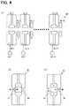
- FIG. 3is a diagram illustrating a quadrupole magnet according to the present embodiment.
- FIG. 4is a diagram showing a schematic configuration of a medium- ⁇ section accelerator 40 according to the present embodiment.
- FIG. 5is a diagram showing a schematic configuration of a high- ⁇ section accelerator 5 according to the present embodiment.
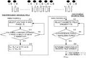
- FIG. 6is a flow chart of an acceleration condition determination process according to the present embodiment.
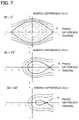
- FIG. 7is a diagram illustrating phase stability of a beam.
- FIG. 8is a table illustrating an advantageous effect of the linear accelerator system 100 according to the present embodiment.
- the present embodimentis a 100 MW-class linear accelerator system 100 which accelerates a deuteron or proton continuous (CW) ion beam of approximately 1 A up to 100 MeV per nucleon (hereinafter, 100 MeV/u, a similar expression applies to same types of descriptions).
- FIG. 1is a diagram showing a schematic configuration example of the linear accelerator system 100 according to the present embodiment.
- a linear accelerator systemis a term that collectively refers to an entirety of a plurality of cascade-connected accelerators.
- the linear accelerator system 100includes an ion source 10 , a buncher 20 , a low- ⁇ (low velocity) section accelerator 30 , a medium- ⁇ (medium velocity) section accelerator 40 , and a high- ⁇ (high velocity) section accelerator 50 .
- the ion source (a beam generation source) 10is a cusped ion source (also known as an electron impact ion source) which forms a cusped magnetic field inside a plasma generation container.
- the ion source 10ionizes gas to generate a plasma and extracts ion with a 30 kV electric field.
- the ion source 10extracts beams from 30 porous electrodes in order to obtain an ion beam of 1 A. Since excessively focusing a beam results in an excessive space-charge force, a single hole diameter is around 1 cm and a diameter of an entire beam extracted from the ion source 10 is around 10 cm or more.
- the buncher 20bunches the ion beam extracted from the ion source 10 without accelerating the ion beam. Since the low- ⁇ section accelerator 30 also has a beam-bunching function, the buncher 20 may be omitted.
- Energy of the ion beam extracted from the ion source 10ranges from 50 to 300 keV/u. In a practical example shown in FIG. 1 , the energy of the ion beam is 100 keV/u.
- the low- ⁇ section accelerator 30is a front-stage accelerator (an initial-stage accelerator) which initially accelerates an ion beam generated by the ion source 10 .
- the low- ⁇ section accelerator 30will also be simply referred to as an accelerator 30 .
- the accelerator 30accelerates ions up to 2 to 7 MeV/u.
- the practical example shown in FIG. 1represents an example in which ions are accelerated up to 5 MeV/u.
- the accelerator 30has a bore diameter of 10 cm or more in order to receive beams generated by the ion source 10 .
- the accelerator 30is configured such that around 20 acceleration cavities 31 _ 1 , 31 _ 2 , . . . , 31 _ 20 and around 20 quadrupole magnets (Q magnets) 32 _ 1 , 32 _ 2 , . . . , 32 _ 20 are alternately connected. Since the respective acceleration cavities and the respective Q magnets share similar configurations, hereinafter, suffixes will be omitted and collective references in the form of an acceleration cavity 31 and a Q magnet 32 will be made.
- the acceleration cavity 31is a single-gap cavity having a single acceleration gap 35 .
- Radiofrequency power(an oscillating electric field) is supplied to the acceleration cavity 31 from a radiofrequency power supplying unit 33 via an RF coupler (a radiofrequency coupling system) 34 .
- the radiofrequency power supplying unit 33supplies the radiofrequency power in a phase in which ions are accelerated when passing through the acceleration gap 35 .
- acceleration voltageis 300 kV and frequency is 25 MHz.
- the radiofrequency power supplying unit 33 provided in each acceleration cavity 31is capable of independently controlling a phase of radiofrequency waves. Therefore, since ions can be accelerated by determining each phase in accordance with spacing between adjacent acceleration cavities (spacing between acceleration gaps), spacing of acceleration cavities can be freely set.
- radiofrequency poweran oscillating electric field supplied by the radiofrequency power supplying unit 33
- the radiofrequency power supplying unit 33corresponds to the first control means according to the present invention.
- the quadrupole magnet 32performs convergence of a beam with a DC magnetic field (a static magnetic field).
- Directions of convergence of adjacent quadrupole magnets 32differ from each other.
- an F quadrupoleFIG. 3(A)
- a D quadrupoleFIG. 3(B)
- an intensity of a magnetic field created by the quadrupole magnet 32is desirably determined in accordance with energy of ions, the intensity is generally around several k gauss.
- the quadrupole magnet 32may be a permanent magnet or an electromagnet, adopting a permanent magnet achieves energy saving.
- the quadrupole magnet 32Due to the DC magnetic field supplied by the quadrupole magnet 32 , a motion and behavior of ions in a transverse direction or, in other words, convergence of the ions is controlled.
- the quadrupole magnet 32corresponds to the second control means according to the present invention.
- the medium- ⁇ section accelerator 40is an accelerator which further accelerates an ion beam accelerated by the low- ⁇ section accelerator 30 .
- the medium- ⁇ section accelerator 40will also be simply referred to as an accelerator 40 .
- the accelerator 40accelerates ions up to 10 to 50 MeV/u.
- the practical example shown in FIG. 1represents an example in which ions are accelerated up to 40 MeV/u.
- the accelerator 40is similar to the accelerator 30 in principle and is configured such that 10 acceleration cavities 41 and 10 Q magnets 42 are alternately connected.
- the acceleration cavity 41is a double-gap cavity having two acceleration gaps 46 and 47 .
- Radiofrequency poweris supplied to the acceleration cavity 41 from a radiofrequency power supplying unit 43 via an RF coupler (a radiofrequency coupling system) 44 .
- RF coupler 44There may be one RF coupler 44 or a plurality of RF couplers 44 .
- the RF coupler 44controls a phase of the radiofrequency power with a digital circuit.
- the radiofrequency power supplying unit 43supplies the radiofrequency power in a phase in which ions are accelerated when passing through the acceleration gaps 45 and 46 .
- the present embodiment shown in FIG. 1represents an example of acceleration conditions including acceleration voltage of 2.5 MV and frequency of 50 MHz.
- the high- ⁇ section accelerator 50is an accelerator which further accelerates an ion beam accelerated by the medium- ⁇ section accelerator 40 .
- the high- ⁇ section accelerator 50will also be simply referred to as an accelerator 50 .
- the accelerator 50accelerates ions up to 75 to 1,000 MeV/u.
- the practical example shown in FIG. 1represents an example in which ions are accelerated up to 200 MeV/u.
- a more specific configuration of the accelerator 50will be described with reference to FIG. 5 .
- the accelerator 50is similar to the accelerators 30 and 40 in principle, a configuration in which one Q magnet 52 is connected downstream to two acceleration cavities 51 is repeated. This is an example in which, as a result of determining acceleration conditions, there are a total of 80 acceleration cavities 51 and 40 Q magnets 52 .
- the acceleration cavity 51is a single-gap cavity having a single acceleration gap 55 .
- Radiofrequency poweris supplied to the acceleration cavity 51 from a radiofrequency power supplying unit 53 via an RF coupler (a radiofrequency coupling system) 54 .
- the radiofrequency power supplying unit 53supplies the radiofrequency power in a phase in which ions are accelerated when passing through the acceleration gap 55 .
- the example of the present embodimentrepresents an example of determining acceleration conditions including acceleration voltage of 2.5 MV and frequency of 100 MHz.
- Q magnet 52F quadrupoles and D quadrupoles are alternately arranged.
- One Q magnet 52is arranged for every two acceleration cavities 51 in the accelerator 50 because, given that energy of a beam is high, an effect of spread of the beam is relatively small.
- the beam accelerated by the accelerator 50is guided to a target area via a high-energy beam transportation system.
- the low- ⁇ section accelerator 30Determination methods of a voltage and a phase of a radiofrequency magnetic field and a magnetic field gradient of a Q magnet in each acceleration gap will be described.
- the acceleration conditionscan be determined by similar processing for all sections. Therefore, hereinafter, the low- ⁇ section accelerator 30 will be mainly described as an example.
- FIG. 6An acceleration condition determination process in the low- ⁇ section accelerator 30 will now be described with reference to FIG. 6 .
- An upper part of FIG. 6schematically shows an acceleration gap g and a quadrupole magnet Q of the accelerator 30 and a bunching velocity v depicted by a block dot. Note that an i-th acceleration gap will be denoted by g i , an i-th Q magnet will be denoted by Q i , and a bunching velocity after passing the acceleration gap g i will be denoted by v i .
- the flow chart shown in FIG. 6represents processing for determining a radiofrequency magnetic field and a convergence magnetic field for one stage.
- the processingis realized by a computer by executing a program.
- Steps S 11 to S 13are steps of processing for determining V i and ⁇ i and steps S 21 to S 23 are steps of processing for determining FG i .
- V idenotes an amplitude of a radiofrequency electric field to be applied to the acceleration gap g i
- ⁇ idenotes a phase of an oscillating electric field when a center of a bunch passes through the acceleration gap
- Q idenotes a magnetic field gradient of the Q magnet Q i which has a positive value in cases of horizontal convergence and vertical divergence and a negative value in cases of vertical convergence and horizontal divergence.
- step S 11processing for determining a radiofrequency electric field of the acceleration gap g i will be described.
- step S 11V i and ⁇ i are selected.
- step S 12a determination is made as to whether or not phase stability of a beam and adiabaticity are satisfied.
- Phase stabilitycan be determined based on whether or not a beam is positioned within a stable region in a phase space defined by a phase difference from a synchronous particle and an energy difference from the synchronous particle.
- a solid line Srepresents separatrix (a stability limit) and inside thereof is a stable region. In other words, a beam is stable when the beam is positioned inside the stable region described above in a phase space.
- An adiabatic conditionis a condition requiring that a variation of a stable space is sufficiently gradual as compared to a synchrotron oscillation of a beam. Specifically, when a synchrotron oscillation frequency is denoted by ⁇ s, the condition requires that (1/ ⁇ s) ⁇ d ⁇ s/dt ⁇ s.
- step S 12when phase stability and adiabaticity are not satisfied, the processing returns to step S 1 to once again select V i and ⁇ i .
- V i and ⁇ i in the acceleration gap g iare determined as the values selected in step S 11 .
- V i and ⁇ iare desirably determined so that highest acceleration efficiency is attained within a range satisfying the conditions of step S 12 .
- step S 21FG i is selected.
- step S 22a determination is made as to whether a condition requiring that a convergence force of the Q magnet exceed a repulsion force due to the space-charge force or, in other words, whether a condition requiring stability in a transverse direction is satisfied.
- the processingreturns to step S 21 to once again select FG i .
- step S 23the processing advances to step S 23 to determine an orientation of the magnetic field gradient.
- the magnetic field gradientis set to a positive direction for odd-numbered Q magnets but the magnetic field gradient is set to a negative direction for even-numbered Q magnets. It is needless to say that positive and negative may be reversed.
- acceleration conditions in the i-th acceleration gap g i and the i-th Q magnet Q iare determined.
- Vi and ⁇ iare determined as described below.
- a small ⁇ i valuemeans low acceleration voltage, while ⁇ i is preferably increased to a value ( ⁇ a, for example, 60°) at which ordinary acceleration is performed as quickly as possible for the purpose of improving acceleration efficiency, it is important that ⁇ i is gradually varied to ensure that the beam does not spill out from the stable region for the purpose of satisfying the adiabatic condition described earlier.
- a frequencyis not fixed across all regions of the accelerator system and, for example, the frequency of the radiofrequency electric field is increased such that a frequency of the medium- ⁇ section is K times that of the low- ⁇ section and a frequency of the high- ⁇ section is L times that of the low- ⁇ section in order to make the entire accelerator system more compact.
- a spread in a phase direction of the beam shown in FIG. 7increases by a factor of K (L) as the frequency varies. Therefore, in an initial stage of medium- ⁇ and high- ⁇ , ⁇ i is set slightly lower than ⁇ a to widen the stable region, and after the beam is captured in the stable region without any spilling, ⁇ i is gradually (adiabatically) brought close to ⁇ a.
- the accelerator according to the present embodimentis an arrangement of a plurality of single-gap or double-gap acceleration cavities, a voltage and a phase of a radiofrequency electric field can be determined as described above for each acceleration cavity.
- the IFMIFis a 10 MW-class accelerator which emits two deuteron beams (40 MeV, 125 mA ⁇ 2).
- FIG. 8is a table which compares characteristics (column 601 ) of an RFQ accelerator that is an initial-stage accelerator in an IFMIF, characteristics (column 602 ) when a bore diameter of the RFQ accelerator in the IFMIF is simply increased by ten times, and characteristics (column 603 ) of the initial-stage accelerator 30 according to the present embodiment.
- the RFQ acceleratorperforms convergence of a beam in the horizontal direction according to an electric field system
- increasing the bore diameter by ten timesalso increases required voltage by ten times (80 kV ⁇ 800 kV).
- a discharge power limitis exceeded.
- the accelerator according to the present embodimentperforms convergence of a beam in the horizontal direction according to a magnetic field system that uses Q magnets, there is no need to apply high voltage to cause the beam to converge even when the bore diameter is increased and can be realized within the discharge power limit.
- radiofrequency lossis proportional to a square of voltage
- increasing the bore diameter of the RFQ accelerator by ten timesresults in an enormous increase in radiofrequency loss of 100 times (1 MV ⁇ 100 MW).
- radiofrequency loss in the accelerator according to the present embodimentcan be kept to or below 10 MW.
- spacing between acceleration gapsmust be set to ⁇ /2.
- the spacing of acceleration cavitiescan be freely designed.
- the acceleration cavitieshave a single acceleration gap, this means that the spacing of all acceleration gaps can be freely designed. Therefore, the spacing of acceleration gaps can be shortened and a reduction of the total length of the acceleration apparatus can be achieved.
- one acceleration cavityhas a plurality of acceleration gaps, while the constraint described above applies to the spacing between acceleration gaps inside the acceleration cavity, since the spacing between acceleration cavities can be shortened, the total length can be reduced as compared to conventional examples. In addition, reducing the total length of accelerators enables production cost to be reduced.
- An RFQ acceleratornot only accelerates a beam and causes the beam to converge in the horizontal direction but also has a function of adiabatically capturing the beam in the direction of travel.
- the accelerator according to the present embodimentis also capable of adiabatically capturing a beam in the direction of travel.
- another advantageis that the number of RF couplers per one acceleration cavity can be reduced. Since there is a limit to power that can be supplied from one RF coupler, radiofrequency power must be supplied from a plurality of RF couplers. For example, at least 8 or 9 RF couplers are needed to supply power of 500 kW. It is difficult to connect such a large number of RF couplers in one acceleration cavity, and it is virtually impossible to increase an acceleration gradient through further extension. In contrast, since the accelerator according to the present embodiment need only one RF coupler per one acceleration cavity, the acceleration cavity can be readily realized and, at the same time, the acceleration gradient can also be increased by increasing the number of RF couplers.
- an accelerator subsystem for a low-velocity regioncan be constructed and adequate control can be realized in correspondence with a velocity region.
- a manufacturing methodcan be adopted in which a plurality of accelerators corresponding to respective velocity regions are manufactured at another location, the accelerators are individually transported to an installation location of an accelerator system, and an entire system is constructed by assembling subsystems of respective velocity regions, in which case various adjustments can be performed on-site after assembly on a cell-by-cell basis in a flexible manner.
- the twoare partitioned and separated in such a manner that the former is controlled based on an oscillating electric field and the latter is controlled based on a static magnetic field and are performed as represented by a procedure shown in, for example, FIG. 6 .
- a behavior of a beam in a cavity that is closest to an ion generation sourcehas no small effect on the behavior of the beam in a cavity in a subsequent stage and also affects controllability of the beam in the subsequent stage.
- the behavior of a beam in a cavity of a specific stagehas a recurrence formula-like effect on beam behavior, control thereof, and the like in cavities of subsequent stages. Therefore, performing partitioning control of the electric field and the magnetic field described above, particularly in the cavity that is closest to the ion generation source, has great significance when considering an effect to a subsequent stage and, by extension, to an entire system.
- the bore diameter (inner diameter) of the acceleratoris set to 10 cm in the embodiment described above, the bore diameter may be smaller or larger. Considering that a bore diameter that can be realized by a conventional RFQ accelerator is around 1 cm, setting the bore diameter of the accelerator according to the present embodiment to 2 cm or more realizes acceleration of a large-diameter beam that is conventionally not feasible.
- the bore diameter of the acceleratormay be 5 cm or more, 10 cm or more, 20 cm or more, or 50 cm or more.
- While the embodiment described aboveis configured such that one Q magnet is connected to every one or two acceleration cavities, other configurations can also be adopted.
- a plurality of Q magnetsmay be continuously arranged.
- a configurationcan be adopted in which M-number (where M is a natural number) of multipole magnets are connected downstream to N-number (where N is a natural number) of acceleration cavities.
- the linear accelerator systemis constituted by three accelerators in a low- ⁇ section, a medium- ⁇ section, and a high- ⁇ section
- the linear accelerator systemmay be constituted by two accelerators or four or more accelerators.
- not all acceleratorsneed be accelerators constituted by acceleration cavities having one or two acceleration gaps.
- an accelerator of an initial stageis preferably configured in this manner, conventional accelerators may be adopted as the accelerators in second and subsequent stages.
- tritiumtritiated hydrogen
- elements heavier than hydrogenmay be accelerated instead.
- While a prominent effect of the present inventioncan be expected when a beam current is around 1 A, a reasonable effect may be produced even when the beam current is at least around 0.1 A.
Landscapes
- Physics & Mathematics (AREA)
- Engineering & Computer Science (AREA)
- Plasma & Fusion (AREA)
- Spectroscopy & Molecular Physics (AREA)
- Particle Accelerators (AREA)
Abstract
Description
- [PTL 1] Japanese Patent Application Laid-open No. H11-283797
- 10 Ion source
- 20 Buncher
- 30 Low-β section accelerator
- 40 Medium-β section accelerator
- 50 High-β section accelerator
- 31,41,51 Acceleration cavity
- 32,42,52 Quadrupole magnet (Q magnet)
- 33,43,53 Radiofrequency power supplying unit
- 34,44,54 Radiofrequency coupling system
- 35,45,46,55 Acceleration gap
Claims (7)
Applications Claiming Priority (4)
| Application Number | Priority Date | Filing Date | Title |
|---|---|---|---|
| JP2018-008235 | 2018-01-22 | ||
| JPJP2018-008235 | 2018-01-22 | ||
| JP2018008235 | 2018-01-22 | ||
| PCT/JP2018/032453WO2019142389A1 (en) | 2018-01-22 | 2018-08-31 | Accelerator and accelerator system |
Publications (2)
| Publication Number | Publication Date |
|---|---|
| US20210076482A1 US20210076482A1 (en) | 2021-03-11 |
| US11432394B2true US11432394B2 (en) | 2022-08-30 |
Family
ID=67302048
Family Applications (1)
| Application Number | Title | Priority Date | Filing Date |
|---|---|---|---|
| US16/963,658ActiveUS11432394B2 (en) | 2018-01-22 | 2018-08-31 | Accelerator and accelerator system |
Country Status (7)
| Country | Link |
|---|---|
| US (1) | US11432394B2 (en) |
| EP (1) | EP3745826A4 (en) |
| JP (1) | JP7318935B2 (en) |
| KR (1) | KR102648177B1 (en) |
| CN (1) | CN111630940B (en) |
| CA (1) | CA3089085A1 (en) |
| WO (1) | WO2019142389A1 (en) |
Families Citing this family (3)
| Publication number | Priority date | Publication date | Assignee | Title |
|---|---|---|---|---|
| CA3089085A1 (en)* | 2018-01-22 | 2019-07-25 | Riken | Accelerator and accelerator system |
| GB2583378A (en) | 2019-04-26 | 2020-10-28 | Elekta ltd | Waveguide for a linear accelerator and method of operating a linear accelerator |
| US11476084B2 (en)* | 2019-09-10 | 2022-10-18 | Applied Materials, Inc. | Apparatus and techniques for ion energy measurement in pulsed ion beams |
Citations (48)
| Publication number | Priority date | Publication date | Assignee | Title |
|---|---|---|---|---|
| JPH04209500A (en) | 1990-11-30 | 1992-07-30 | Hitachi Ltd | Ion beam accelerator/decelerator |
| JPH06231900A (en) | 1993-02-04 | 1994-08-19 | Mitsubishi Electric Corp | Linear electron accelerator |
| JPH06349599A (en) | 1993-06-14 | 1994-12-22 | Mitsubishi Electric Corp | Charged particle accelerator |
| US5757009A (en)* | 1996-12-27 | 1998-05-26 | Northrop Grumman Corporation | Charged particle beam expander |
| US5841237A (en)* | 1997-07-14 | 1998-11-24 | Lockheed Martin Energy Research Corporation | Production of large resonant plasma volumes in microwave electron cyclotron resonance ion sources |
| JPH11283797A (en) | 1998-03-27 | 1999-10-15 | Nissin Electric Co Ltd | High frequency quadrupole accelerator |
| JP2001085198A (en) | 1999-09-16 | 2001-03-30 | Mitsubishi Heavy Ind Ltd | Linear accelerator, controlling method for linear accelerator, and recording medium on which control program of linear accelerator is recorded |
| US6476399B1 (en)* | 2000-09-01 | 2002-11-05 | Axcelis Technologies, Inc. | System and method for removing contaminant particles relative to an ion beam |
| US20030183779A1 (en)* | 2002-03-26 | 2003-10-02 | Tetsuro Norimine | Particle therapy system |
| US20040084634A1 (en)* | 2001-02-05 | 2004-05-06 | Alexander Bechthold | Apparatus for pre-acceleration of ion beams used in a heavy ion beam applications system |
| US20040108823A1 (en)* | 2002-12-09 | 2004-06-10 | Fondazione Per Adroterapia Oncologica - Tera | Linac for ion beam acceleration |
| US6777893B1 (en)* | 2002-05-02 | 2004-08-17 | Linac Systems, Llc | Radio frequency focused interdigital linear accelerator |
| US20040212331A1 (en)* | 2002-05-02 | 2004-10-28 | Swenson Donald A. | Radio frequency focused interdigital linear accelerator |
| US20070164237A1 (en)* | 2006-01-18 | 2007-07-19 | Axcelis Technologies, Inc. | Application of digital frequency and phase synthesis for control of electrode voltage phase in a high-energy ion implantation machine, and a means for accurate calibration of electrode voltage phase |
| US20070170994A1 (en)* | 2006-01-24 | 2007-07-26 | Peggs Stephen G | Rapid cycling medical synchrotron and beam delivery system |
| US20080128641A1 (en)* | 2006-11-08 | 2008-06-05 | Silicon Genesis Corporation | Apparatus and method for introducing particles using a radio frequency quadrupole linear accelerator for semiconductor materials |
| US7554275B2 (en)* | 2005-11-11 | 2009-06-30 | Fondazione Per Adroterapia Oncologica - Tera | Proton accelerator complex for radio-isotopes and therapy |
| US20090302785A1 (en)* | 2008-06-04 | 2009-12-10 | Miller Roger H | Slot resonance coupled standing wave linear particle accelerator |
| US20100060209A1 (en)* | 2008-05-22 | 2010-03-11 | Vladimir Balakin | Rf accelerator method and apparatus used in conjunction with a charged particle cancer therapy system |
| US20100060208A1 (en)* | 2008-09-09 | 2010-03-11 | Swenson Donald A | Quarter-Wave-Stub Resonant Coupler |
| US20100290575A1 (en)* | 2009-05-15 | 2010-11-18 | Rosenthal Glenn B | Particle beam isotope generator apparatus, system and method |
| US20120086364A1 (en)* | 2010-10-06 | 2012-04-12 | Lawrence Livermore National Security, Llc | Particle beam coupling system and method |
| US20120126727A1 (en)* | 2010-11-19 | 2012-05-24 | Hamm Robert W | Sub-Nanosecond Beam Pulse Radio Frequency Quadrupole (RFQ) Linear Accelerator System |
| US20120181456A1 (en)* | 2011-01-04 | 2012-07-19 | Lawrence Livermore National Security, Llc | Systems and methods of varying charged particle beam spot size |
| US20120313003A1 (en)* | 2006-05-12 | 2012-12-13 | Brookhaven Science Associates, Llc | Gantry for Medical Particle Therapy Facility |
| US20130038248A1 (en)* | 2010-07-12 | 2013-02-14 | Kazuo Yamamoto | Drift-tube linear accelerator |
| US20130051508A1 (en)* | 2010-08-31 | 2013-02-28 | Texas A&M University System | Accelerator driven sub-critical core |
| US20130092111A1 (en)* | 2010-06-14 | 2013-04-18 | Toyota Jidosha Kabushiki Kaisha | Control device of actuator |
| US8575868B2 (en)* | 2009-04-16 | 2013-11-05 | Lawrence Livermore National Security, Llc | Virtual gap dielectric wall accelerator |
| US8624528B2 (en)* | 2008-05-22 | 2014-01-07 | Vladimir Balakin | Method and apparatus coordinating synchrotron acceleration periods with patient respiration periods |
| US8907309B2 (en)* | 2009-04-17 | 2014-12-09 | Stephen L. Spotts | Treatment delivery control system and method of operation thereof |
| US20150005567A1 (en)* | 2013-06-27 | 2015-01-01 | Brookhaven Science Associates, Llc | Multi Turn Beam Extraction from Synchrotron |
| US8933651B2 (en)* | 2012-11-16 | 2015-01-13 | Vladimir Balakin | Charged particle accelerator magnet apparatus and method of use thereof |
| US8941084B2 (en)* | 2008-05-22 | 2015-01-27 | Vladimir Balakin | Charged particle cancer therapy dose distribution method and apparatus |
| US20150362565A1 (en)* | 2013-01-24 | 2015-12-17 | Paul Scherrer Institut | Method for manufacturing a hall sensor assembly and a hall sensor assembly |
| US9629230B1 (en)* | 2016-02-24 | 2017-04-18 | Jefferson Science Associates, Llc | RF kicker cavity to increase control in common transport lines |
| US20170238408A1 (en)* | 2014-08-15 | 2017-08-17 | Cern European Organization For Nuclear Research | High frequency compact low-energy linear accelerator design |
| US20170372867A1 (en)* | 2015-01-12 | 2017-12-28 | The Regents Of The University Of California | Left-right canted-cosine-theta magnets |
| US20180047473A1 (en)* | 2015-03-20 | 2018-02-15 | Riken | Radioactive waste processing method |
| US20180292481A1 (en)* | 2017-03-31 | 2018-10-11 | Bruker Biospin Gmbh | Permanent magnet arrangement for mr apparatuses with axially and laterally displaceable, rotatably mounted ring modules |
| US20190043631A1 (en)* | 2016-02-03 | 2019-02-07 | Riken | Method for preparing radioactive substance through muon irradiation, and substance prepared using said method |
| WO2019043070A2 (en) | 2017-08-29 | 2019-03-07 | Alceli Limited | Linear accelerating structure for protons |
| US10245448B2 (en)* | 2017-07-21 | 2019-04-02 | Varian Medical Systems Particle Therapy Gmbh | Particle beam monitoring systems and methods |
| US10362666B2 (en)* | 2017-05-25 | 2019-07-23 | Uchicago Argonne, Llc | Compac carbon ion LINAC |
| US20190239333A1 (en)* | 2017-03-24 | 2019-08-01 | Hitachi, Ltd. | Circular accelerator |
| US10566169B1 (en)* | 2008-06-30 | 2020-02-18 | Nexgen Semi Holding, Inc. | Method and device for spatial charged particle bunching |
| US10609806B2 (en)* | 2017-07-21 | 2020-03-31 | Varian Medical Systems Particle Therapy Gmbh | Energy modulation of a cyclotron beam |
| US20210076482A1 (en)* | 2018-01-22 | 2021-03-11 | Riken | Accelerator and accelerator system |
Family Cites Families (4)
| Publication number | Priority date | Publication date | Assignee | Title |
|---|---|---|---|---|
| JPH01214000A (en)* | 1988-02-23 | 1989-08-28 | Mitsubishi Electric Corp | linear accelerator |
| JP2932473B2 (en)* | 1996-03-27 | 1999-08-09 | 日新電機株式会社 | High-frequency charged particle accelerator |
| US20090224700A1 (en)* | 2004-01-15 | 2009-09-10 | Yu-Jiuan Chen | Beam Transport System and Method for Linear Accelerators |
| CN103167718B (en)* | 2013-02-27 | 2015-06-10 | 北京大学 | Single-mandril spoke type superconduction accelerating cavity and manufacture method thereof |
- 2018
- 2018-08-31CACA3089085Apatent/CA3089085A1/enactivePending
- 2018-08-31JPJP2019565700Apatent/JP7318935B2/enactiveActive
- 2018-08-31EPEP18901222.2Apatent/EP3745826A4/enactivePending
- 2018-08-31KRKR1020207022084Apatent/KR102648177B1/enactiveActive
- 2018-08-31USUS16/963,658patent/US11432394B2/enactiveActive
- 2018-08-31CNCN201880087353.6Apatent/CN111630940B/enactiveActive
- 2018-08-31WOPCT/JP2018/032453patent/WO2019142389A1/ennot_activeCeased
Patent Citations (54)
| Publication number | Priority date | Publication date | Assignee | Title |
|---|---|---|---|---|
| JPH04209500A (en) | 1990-11-30 | 1992-07-30 | Hitachi Ltd | Ion beam accelerator/decelerator |
| JPH06231900A (en) | 1993-02-04 | 1994-08-19 | Mitsubishi Electric Corp | Linear electron accelerator |
| JPH06349599A (en) | 1993-06-14 | 1994-12-22 | Mitsubishi Electric Corp | Charged particle accelerator |
| US5757009A (en)* | 1996-12-27 | 1998-05-26 | Northrop Grumman Corporation | Charged particle beam expander |
| US5841237A (en)* | 1997-07-14 | 1998-11-24 | Lockheed Martin Energy Research Corporation | Production of large resonant plasma volumes in microwave electron cyclotron resonance ion sources |
| JPH11283797A (en) | 1998-03-27 | 1999-10-15 | Nissin Electric Co Ltd | High frequency quadrupole accelerator |
| JP2001085198A (en) | 1999-09-16 | 2001-03-30 | Mitsubishi Heavy Ind Ltd | Linear accelerator, controlling method for linear accelerator, and recording medium on which control program of linear accelerator is recorded |
| US6476399B1 (en)* | 2000-09-01 | 2002-11-05 | Axcelis Technologies, Inc. | System and method for removing contaminant particles relative to an ion beam |
| US20040084634A1 (en)* | 2001-02-05 | 2004-05-06 | Alexander Bechthold | Apparatus for pre-acceleration of ion beams used in a heavy ion beam applications system |
| US20050134204A1 (en)* | 2001-02-05 | 2005-06-23 | Alexander Bechthold | Apparatus for pre-acceleration of ion beams used in a heavy ion beam application system |
| US20030183779A1 (en)* | 2002-03-26 | 2003-10-02 | Tetsuro Norimine | Particle therapy system |
| US20050247890A1 (en)* | 2002-03-26 | 2005-11-10 | Tetsuro Norimine | Particle therapy system |
| US6777893B1 (en)* | 2002-05-02 | 2004-08-17 | Linac Systems, Llc | Radio frequency focused interdigital linear accelerator |
| US20040212331A1 (en)* | 2002-05-02 | 2004-10-28 | Swenson Donald A. | Radio frequency focused interdigital linear accelerator |
| US20040108823A1 (en)* | 2002-12-09 | 2004-06-10 | Fondazione Per Adroterapia Oncologica - Tera | Linac for ion beam acceleration |
| US7554275B2 (en)* | 2005-11-11 | 2009-06-30 | Fondazione Per Adroterapia Oncologica - Tera | Proton accelerator complex for radio-isotopes and therapy |
| US20070164237A1 (en)* | 2006-01-18 | 2007-07-19 | Axcelis Technologies, Inc. | Application of digital frequency and phase synthesis for control of electrode voltage phase in a high-energy ion implantation machine, and a means for accurate calibration of electrode voltage phase |
| US20070170994A1 (en)* | 2006-01-24 | 2007-07-26 | Peggs Stephen G | Rapid cycling medical synchrotron and beam delivery system |
| US20120313003A1 (en)* | 2006-05-12 | 2012-12-13 | Brookhaven Science Associates, Llc | Gantry for Medical Particle Therapy Facility |
| US20080128641A1 (en)* | 2006-11-08 | 2008-06-05 | Silicon Genesis Corporation | Apparatus and method for introducing particles using a radio frequency quadrupole linear accelerator for semiconductor materials |
| US8941084B2 (en)* | 2008-05-22 | 2015-01-27 | Vladimir Balakin | Charged particle cancer therapy dose distribution method and apparatus |
| US20100060209A1 (en)* | 2008-05-22 | 2010-03-11 | Vladimir Balakin | Rf accelerator method and apparatus used in conjunction with a charged particle cancer therapy system |
| US8624528B2 (en)* | 2008-05-22 | 2014-01-07 | Vladimir Balakin | Method and apparatus coordinating synchrotron acceleration periods with patient respiration periods |
| US20090302785A1 (en)* | 2008-06-04 | 2009-12-10 | Miller Roger H | Slot resonance coupled standing wave linear particle accelerator |
| US7898193B2 (en)* | 2008-06-04 | 2011-03-01 | Far-Tech, Inc. | Slot resonance coupled standing wave linear particle accelerator |
| US10566169B1 (en)* | 2008-06-30 | 2020-02-18 | Nexgen Semi Holding, Inc. | Method and device for spatial charged particle bunching |
| US20100060208A1 (en)* | 2008-09-09 | 2010-03-11 | Swenson Donald A | Quarter-Wave-Stub Resonant Coupler |
| US8575868B2 (en)* | 2009-04-16 | 2013-11-05 | Lawrence Livermore National Security, Llc | Virtual gap dielectric wall accelerator |
| US8907309B2 (en)* | 2009-04-17 | 2014-12-09 | Stephen L. Spotts | Treatment delivery control system and method of operation thereof |
| US20100289409A1 (en)* | 2009-05-15 | 2010-11-18 | Rosenthal Glenn B | Particle beam source apparatus, system and method |
| US20100290575A1 (en)* | 2009-05-15 | 2010-11-18 | Rosenthal Glenn B | Particle beam isotope generator apparatus, system and method |
| US9659736B2 (en)* | 2009-05-15 | 2017-05-23 | Alpha Source, Inc. | Particle beam isotope generator apparatus, system and method |
| US20130092111A1 (en)* | 2010-06-14 | 2013-04-18 | Toyota Jidosha Kabushiki Kaisha | Control device of actuator |
| US20130038248A1 (en)* | 2010-07-12 | 2013-02-14 | Kazuo Yamamoto | Drift-tube linear accelerator |
| US20130051508A1 (en)* | 2010-08-31 | 2013-02-28 | Texas A&M University System | Accelerator driven sub-critical core |
| US20120086364A1 (en)* | 2010-10-06 | 2012-04-12 | Lawrence Livermore National Security, Llc | Particle beam coupling system and method |
| US20120126727A1 (en)* | 2010-11-19 | 2012-05-24 | Hamm Robert W | Sub-Nanosecond Beam Pulse Radio Frequency Quadrupole (RFQ) Linear Accelerator System |
| US20120181456A1 (en)* | 2011-01-04 | 2012-07-19 | Lawrence Livermore National Security, Llc | Systems and methods of varying charged particle beam spot size |
| US8933651B2 (en)* | 2012-11-16 | 2015-01-13 | Vladimir Balakin | Charged particle accelerator magnet apparatus and method of use thereof |
| US20150362565A1 (en)* | 2013-01-24 | 2015-12-17 | Paul Scherrer Institut | Method for manufacturing a hall sensor assembly and a hall sensor assembly |
| US20150005567A1 (en)* | 2013-06-27 | 2015-01-01 | Brookhaven Science Associates, Llc | Multi Turn Beam Extraction from Synchrotron |
| US20170238408A1 (en)* | 2014-08-15 | 2017-08-17 | Cern European Organization For Nuclear Research | High frequency compact low-energy linear accelerator design |
| US10051721B2 (en)* | 2014-08-15 | 2018-08-14 | CERN—European Organization for Nuclear Research | High frequency compact low-energy linear accelerator design |
| US20170372867A1 (en)* | 2015-01-12 | 2017-12-28 | The Regents Of The University Of California | Left-right canted-cosine-theta magnets |
| US20180047473A1 (en)* | 2015-03-20 | 2018-02-15 | Riken | Radioactive waste processing method |
| US20190043631A1 (en)* | 2016-02-03 | 2019-02-07 | Riken | Method for preparing radioactive substance through muon irradiation, and substance prepared using said method |
| US9629230B1 (en)* | 2016-02-24 | 2017-04-18 | Jefferson Science Associates, Llc | RF kicker cavity to increase control in common transport lines |
| US20190239333A1 (en)* | 2017-03-24 | 2019-08-01 | Hitachi, Ltd. | Circular accelerator |
| US20180292481A1 (en)* | 2017-03-31 | 2018-10-11 | Bruker Biospin Gmbh | Permanent magnet arrangement for mr apparatuses with axially and laterally displaceable, rotatably mounted ring modules |
| US10362666B2 (en)* | 2017-05-25 | 2019-07-23 | Uchicago Argonne, Llc | Compac carbon ion LINAC |
| US10245448B2 (en)* | 2017-07-21 | 2019-04-02 | Varian Medical Systems Particle Therapy Gmbh | Particle beam monitoring systems and methods |
| US10609806B2 (en)* | 2017-07-21 | 2020-03-31 | Varian Medical Systems Particle Therapy Gmbh | Energy modulation of a cyclotron beam |
| WO2019043070A2 (en) | 2017-08-29 | 2019-03-07 | Alceli Limited | Linear accelerating structure for protons |
| US20210076482A1 (en)* | 2018-01-22 | 2021-03-11 | Riken | Accelerator and accelerator system |
Non-Patent Citations (10)
| Title |
|---|
| Barni, "Status of the Trasco Project," The 10th Workshop on RF Superconductivity, Tsukuba, Japan, 2001, pp. 337-346, 10 pages total. |
| Biarrotte et al., "Design of the MYRRHA17-600 MeV Superconducting Linac," Proceedings of SRF2013, Paris, France, 2013, pp. 129-132, 4 pages total. |
| Biarrotte et al., "High-Intensity Protons SC Linac Using Spoke Cavities," Proceedings of EPAC, Paris, France, 2002, pp. 1010-1012, 3 pages total. |
| Extended European Search Report for European Application No. 18901222.2, dated Sep. 16, 2021. |
| Inaoka et al., "Study of Beam Capture Method for High Repetition Rate at Kyushu University", Proceedings of the 10th Annual Meeting of Particle Accelerator Society of Japan, Jun. 13, 2014, pp. 452-455. |
| International Search Report (PCT/ISA/210) issued in PCT/JP2018/032453 dated Nov. 6, 2018. |
| Krawczyk et al.,"Design of a β=0.175 2-Gap Spoke Resonator," The 10th Workshop on RF Superconductivity, Tsukuba, Japan, 2001, pp. 485-488, 4 pages total. |
| Olry et al., "Recent Developments on Superconducting β035 and β015 Spoke Cavities at IPN for Low and Medium Energy Sections of Proton Linear Accelerators," Proceedings of EPAC, Lucerne, Switzerland, 2004, pp. 1003-1005, 3 pages total. |
| Plostinar et al., "Re-Bunching RF Cavities and Hybrid Quadrupoles for the RAL Front-End Test Stand (FETS)," Proceedings of EPAC, Edinburgh, Scotland, 2006, pp. 306-308, 3 pages total. |
| Written Opinion (PCT/lSA/237) issued in PCT/JP2018/032453 dated Nov. 6, 2018. |
Also Published As
| Publication number | Publication date |
|---|---|
| KR102648177B1 (en) | 2024-03-18 |
| US20210076482A1 (en) | 2021-03-11 |
| WO2019142389A1 (en) | 2019-07-25 |
| EP3745826A1 (en) | 2020-12-02 |
| EP3745826A4 (en) | 2021-10-20 |
| CN111630940B (en) | 2023-10-17 |
| CN111630940A (en) | 2020-09-04 |
| JPWO2019142389A1 (en) | 2021-01-07 |
| KR20200109324A (en) | 2020-09-22 |
| CA3089085A1 (en) | 2019-07-25 |
| JP7318935B2 (en) | 2023-08-01 |
Similar Documents
| Publication | Publication Date | Title |
|---|---|---|
| Takayama et al. | Induction acceleration of heavy ions in the KEK digital accelerator: Demonstration of a fast-cycling induction synchrotron | |
| US11432394B2 (en) | Accelerator and accelerator system | |
| Gilardoni et al. | Fifty years of the CERN Proton Synchrotron: Volume 2 | |
| Takayama et al. | Racetrack-shape fixed field induction accelerator for giant cluster ions | |
| Catalan-Lasheras et al. | JACOW: High-efficiency klystrons from a dream to a reality | |
| Dubniuk et al. | Radiation complex on the basis of helium ions linac | |
| Winklehner et al. | An RFQ Direct Injection Scheme for the IsoDAR High Intensity $\mathrm {H} _2^+ $ Cyclotron | |
| Barth et al. | Development of the UNILAC towards a Megawatt Beam Injector | |
| Jameson | High-brightness RF linear accelerators | |
| Seidel | Cyclotrons for high-intensity beams | |
| Lozeeva et al. | Beam Dynamics Simulation in the LINAC-100 Accelerator Driver for the DERICA Project | |
| Alexeev et al. | Status of the terawatt accumulator accelerator project | |
| Winklehner et al. | High-current H 2+ beams from a compact cyclotron using RFQ direct injection | |
| Seidl et al. | Multiple beam induction accelerators for heavy ion fusion | |
| Schlitt et al. | Design studies for a new heavy ion injector linac for FAIR | |
| Takeuchi | Development of a muon linac for the J-PARC Muon g− 2/EDM experiment | |
| Wuensch | Advances in high-gradient accelerating structures and in the understanding gradient limits | |
| Marchetto | ISAC-II operation and future plans | |
| Pozdeyev et al. | Status of the FRIB front end | |
| Kim et al. | Design for simultaneous acceleration of stable and unstable beams in a superconducting heavy-ion linear accelerator for RISP | |
| Alesini | Linear accelerators | |
| Park et al. | Multipass Simulations of Space Charge Compensation using Electron Columns at IOTA | |
| Kelisani et al. | Design and beamloading-simulations of a prebunching cavity for the CLIC drive beam injector | |
| Chauvin et al. | Start-to-End beam dynamics simulations for the prototype accelerator of the IFMIF/EVEDA project | |
| Buakor et al. | Development of linac-based MIR/THz FEL facility and photocathode RF-gun in Thailand |
Legal Events
| Date | Code | Title | Description |
|---|---|---|---|
| FEPP | Fee payment procedure | Free format text:ENTITY STATUS SET TO UNDISCOUNTED (ORIGINAL EVENT CODE: BIG.); ENTITY STATUS OF PATENT OWNER: LARGE ENTITY | |
| AS | Assignment | Owner name:RIKEN, JAPAN Free format text:ASSIGNMENT OF ASSIGNORS INTEREST;ASSIGNORS:SAKURAI, HIROYOSHI;OKUNO, HIROKI;MORI, YOSHIHARU;AND OTHERS;SIGNING DATES FROM 20200630 TO 20200729;REEL/FRAME:053559/0144 | |
| STPP | Information on status: patent application and granting procedure in general | Free format text:NON FINAL ACTION MAILED | |
| STPP | Information on status: patent application and granting procedure in general | Free format text:RESPONSE TO NON-FINAL OFFICE ACTION ENTERED AND FORWARDED TO EXAMINER | |
| STPP | Information on status: patent application and granting procedure in general | Free format text:FINAL REJECTION MAILED | |
| STPP | Information on status: patent application and granting procedure in general | Free format text:RESPONSE AFTER FINAL ACTION FORWARDED TO EXAMINER | |
| STPP | Information on status: patent application and granting procedure in general | Free format text:ADVISORY ACTION MAILED | |
| STPP | Information on status: patent application and granting procedure in general | Free format text:DOCKETED NEW CASE - READY FOR EXAMINATION | |
| STPP | Information on status: patent application and granting procedure in general | Free format text:NON FINAL ACTION MAILED | |
| STPP | Information on status: patent application and granting procedure in general | Free format text:RESPONSE TO NON-FINAL OFFICE ACTION ENTERED AND FORWARDED TO EXAMINER | |
| STPP | Information on status: patent application and granting procedure in general | Free format text:NOTICE OF ALLOWANCE MAILED -- APPLICATION RECEIVED IN OFFICE OF PUBLICATIONS | |
| STPP | Information on status: patent application and granting procedure in general | Free format text:PUBLICATIONS -- ISSUE FEE PAYMENT VERIFIED | |
| STCF | Information on status: patent grant | Free format text:PATENTED CASE |