US11427153B2 - Vehicle anti-theft device - Google Patents
Vehicle anti-theft deviceDownload PDFInfo
- Publication number
- US11427153B2 US11427153B2US16/329,974US201616329974AUS11427153B2US 11427153 B2US11427153 B2US 11427153B2US 201616329974 AUS201616329974 AUS 201616329974AUS 11427153 B2US11427153 B2US 11427153B2
- Authority
- US
- United States
- Prior art keywords
- vehicle
- locking member
- theft device
- control unit
- electronic control
- Prior art date
- Legal status (The legal status is an assumption and is not a legal conclusion. Google has not performed a legal analysis and makes no representation as to the accuracy of the status listed.)
- Active, expires
Links
- 230000005540biological transmissionEffects0.000claimsdescription16
- 238000004891communicationMethods0.000claimsdescription16
- 230000033001locomotionEffects0.000claimsdescription13
- 230000004044responseEffects0.000claimsdescription6
- 238000006073displacement reactionMethods0.000claimsdescription4
- 230000010267cellular communicationEffects0.000claimsdescription3
- 230000007246mechanismEffects0.000description6
- 230000008878couplingEffects0.000description4
- 238000010168coupling processMethods0.000description4
- 238000005859coupling reactionMethods0.000description4
- 238000000034methodMethods0.000description4
- 230000008901benefitEffects0.000description3
- 230000015572biosynthetic processEffects0.000description3
- 238000005755formation reactionMethods0.000description3
- 230000000295complement effectEffects0.000description2
- 230000010354integrationEffects0.000description2
- 230000013011matingEffects0.000description2
- 238000009420retrofittingMethods0.000description2
- 230000003213activating effectEffects0.000description1
- 230000004913activationEffects0.000description1
- 230000006978adaptationEffects0.000description1
- 230000009286beneficial effectEffects0.000description1
- 238000001514detection methodMethods0.000description1
- 238000010586diagramMethods0.000description1
- 239000000446fuelSubstances0.000description1
- 238000003780insertionMethods0.000description1
- 230000037431insertionEffects0.000description1
- 230000002452interceptive effectEffects0.000description1
- 238000004519manufacturing processMethods0.000description1
- 239000002184metalSubstances0.000description1
- 238000012986modificationMethods0.000description1
- 230000004048modificationEffects0.000description1
- 230000002093peripheral effectEffects0.000description1
- 230000037452primingEffects0.000description1
- 230000008439repair processEffects0.000description1
- 239000007858starting materialSubstances0.000description1
- 238000011144upstream manufacturingMethods0.000description1
Images


Classifications
- B—PERFORMING OPERATIONS; TRANSPORTING
- B60—VEHICLES IN GENERAL
- B60R—VEHICLES, VEHICLE FITTINGS, OR VEHICLE PARTS, NOT OTHERWISE PROVIDED FOR
- B60R25/00—Fittings or systems for preventing or indicating unauthorised use or theft of vehicles
- B60R25/01—Fittings or systems for preventing or indicating unauthorised use or theft of vehicles operating on vehicle systems or fittings, e.g. on doors, seats or windscreens
- B60R25/04—Fittings or systems for preventing or indicating unauthorised use or theft of vehicles operating on vehicle systems or fittings, e.g. on doors, seats or windscreens operating on the propulsion system, e.g. engine or drive motor
- B—PERFORMING OPERATIONS; TRANSPORTING
- B60—VEHICLES IN GENERAL
- B60K—ARRANGEMENT OR MOUNTING OF PROPULSION UNITS OR OF TRANSMISSIONS IN VEHICLES; ARRANGEMENT OR MOUNTING OF PLURAL DIVERSE PRIME-MOVERS IN VEHICLES; AUXILIARY DRIVES FOR VEHICLES; INSTRUMENTATION OR DASHBOARDS FOR VEHICLES; ARRANGEMENTS IN CONNECTION WITH COOLING, AIR INTAKE, GAS EXHAUST OR FUEL SUPPLY OF PROPULSION UNITS IN VEHICLES
- B60K28/00—Safety devices for propulsion-unit control, specially adapted for, or arranged in, vehicles, e.g. preventing fuel supply or ignition in the event of potentially dangerous conditions
- B60K28/10—Safety devices for propulsion-unit control, specially adapted for, or arranged in, vehicles, e.g. preventing fuel supply or ignition in the event of potentially dangerous conditions responsive to conditions relating to the vehicle
- B60K28/16—Safety devices for propulsion-unit control, specially adapted for, or arranged in, vehicles, e.g. preventing fuel supply or ignition in the event of potentially dangerous conditions responsive to conditions relating to the vehicle responsive to, or preventing, spinning or skidding of wheels
- B60K28/165—Safety devices for propulsion-unit control, specially adapted for, or arranged in, vehicles, e.g. preventing fuel supply or ignition in the event of potentially dangerous conditions responsive to conditions relating to the vehicle responsive to, or preventing, spinning or skidding of wheels acting on elements of the vehicle drive train other than the propulsion unit and brakes, e.g. transmission, clutch, differential
- B—PERFORMING OPERATIONS; TRANSPORTING
- B60—VEHICLES IN GENERAL
- B60R—VEHICLES, VEHICLE FITTINGS, OR VEHICLE PARTS, NOT OTHERWISE PROVIDED FOR
- B60R16/00—Electric or fluid circuits specially adapted for vehicles and not otherwise provided for; Arrangement of elements of electric or fluid circuits specially adapted for vehicles and not otherwise provided for
- B60R16/02—Electric or fluid circuits specially adapted for vehicles and not otherwise provided for; Arrangement of elements of electric or fluid circuits specially adapted for vehicles and not otherwise provided for electric constitutive elements
- B60R16/023—Electric or fluid circuits specially adapted for vehicles and not otherwise provided for; Arrangement of elements of electric or fluid circuits specially adapted for vehicles and not otherwise provided for electric constitutive elements for transmission of signals between vehicle parts or subsystems
- B—PERFORMING OPERATIONS; TRANSPORTING
- B60—VEHICLES IN GENERAL
- B60R—VEHICLES, VEHICLE FITTINGS, OR VEHICLE PARTS, NOT OTHERWISE PROVIDED FOR
- B60R16/00—Electric or fluid circuits specially adapted for vehicles and not otherwise provided for; Arrangement of elements of electric or fluid circuits specially adapted for vehicles and not otherwise provided for
- B60R16/02—Electric or fluid circuits specially adapted for vehicles and not otherwise provided for; Arrangement of elements of electric or fluid circuits specially adapted for vehicles and not otherwise provided for electric constitutive elements
- B60R16/03—Electric or fluid circuits specially adapted for vehicles and not otherwise provided for; Arrangement of elements of electric or fluid circuits specially adapted for vehicles and not otherwise provided for electric constitutive elements for supply of electrical power to vehicle subsystems or for
- B60R16/033—Electric or fluid circuits specially adapted for vehicles and not otherwise provided for; Arrangement of elements of electric or fluid circuits specially adapted for vehicles and not otherwise provided for electric constitutive elements for supply of electrical power to vehicle subsystems or for characterised by the use of electrical cells or batteries
- B—PERFORMING OPERATIONS; TRANSPORTING
- B60—VEHICLES IN GENERAL
- B60R—VEHICLES, VEHICLE FITTINGS, OR VEHICLE PARTS, NOT OTHERWISE PROVIDED FOR
- B60R25/00—Fittings or systems for preventing or indicating unauthorised use or theft of vehicles
- B60R25/01—Fittings or systems for preventing or indicating unauthorised use or theft of vehicles operating on vehicle systems or fittings, e.g. on doors, seats or windscreens
- B60R25/04—Fittings or systems for preventing or indicating unauthorised use or theft of vehicles operating on vehicle systems or fittings, e.g. on doors, seats or windscreens operating on the propulsion system, e.g. engine or drive motor
- B60R25/06—Fittings or systems for preventing or indicating unauthorised use or theft of vehicles operating on vehicle systems or fittings, e.g. on doors, seats or windscreens operating on the propulsion system, e.g. engine or drive motor operating on the vehicle transmission
- B—PERFORMING OPERATIONS; TRANSPORTING
- B60—VEHICLES IN GENERAL
- B60R—VEHICLES, VEHICLE FITTINGS, OR VEHICLE PARTS, NOT OTHERWISE PROVIDED FOR
- B60R25/00—Fittings or systems for preventing or indicating unauthorised use or theft of vehicles
- B60R25/10—Fittings or systems for preventing or indicating unauthorised use or theft of vehicles actuating a signalling device
- B—PERFORMING OPERATIONS; TRANSPORTING
- B60—VEHICLES IN GENERAL
- B60R—VEHICLES, VEHICLE FITTINGS, OR VEHICLE PARTS, NOT OTHERWISE PROVIDED FOR
- B60R25/00—Fittings or systems for preventing or indicating unauthorised use or theft of vehicles
- B60R25/20—Means to switch the anti-theft system on or off
- B60R25/24—Means to switch the anti-theft system on or off using electronic identifiers containing a code not memorised by the user
- B60R25/243—Means to switch the anti-theft system on or off using electronic identifiers containing a code not memorised by the user with more than one way to gain access
- B—PERFORMING OPERATIONS; TRANSPORTING
- B60—VEHICLES IN GENERAL
- B60R—VEHICLES, VEHICLE FITTINGS, OR VEHICLE PARTS, NOT OTHERWISE PROVIDED FOR
- B60R25/00—Fittings or systems for preventing or indicating unauthorised use or theft of vehicles
- B60R25/20—Means to switch the anti-theft system on or off
- B60R25/25—Means to switch the anti-theft system on or off using biometry
- B—PERFORMING OPERATIONS; TRANSPORTING
- B60—VEHICLES IN GENERAL
- B60R—VEHICLES, VEHICLE FITTINGS, OR VEHICLE PARTS, NOT OTHERWISE PROVIDED FOR
- B60R25/00—Fittings or systems for preventing or indicating unauthorised use or theft of vehicles
- B60R25/30—Detection related to theft or to other events relevant to anti-theft systems
- B60R25/32—Detection related to theft or to other events relevant to anti-theft systems of vehicle dynamic parameters, e.g. speed or acceleration
- B—PERFORMING OPERATIONS; TRANSPORTING
- B60—VEHICLES IN GENERAL
- B60R—VEHICLES, VEHICLE FITTINGS, OR VEHICLE PARTS, NOT OTHERWISE PROVIDED FOR
- B60R25/00—Fittings or systems for preventing or indicating unauthorised use or theft of vehicles
- B60R25/30—Detection related to theft or to other events relevant to anti-theft systems
- B60R25/33—Detection related to theft or to other events relevant to anti-theft systems of global position, e.g. by providing GPS coordinates
- B—PERFORMING OPERATIONS; TRANSPORTING
- B60—VEHICLES IN GENERAL
- B60R—VEHICLES, VEHICLE FITTINGS, OR VEHICLE PARTS, NOT OTHERWISE PROVIDED FOR
- B60R25/00—Fittings or systems for preventing or indicating unauthorised use or theft of vehicles
- B60R25/30—Detection related to theft or to other events relevant to anti-theft systems
- B60R25/34—Detection related to theft or to other events relevant to anti-theft systems of conditions of vehicle components, e.g. of windows, door locks or gear selectors
- B—PERFORMING OPERATIONS; TRANSPORTING
- B60—VEHICLES IN GENERAL
- B60R—VEHICLES, VEHICLE FITTINGS, OR VEHICLE PARTS, NOT OTHERWISE PROVIDED FOR
- B60R25/00—Fittings or systems for preventing or indicating unauthorised use or theft of vehicles
- B60R25/40—Features of the power supply for the anti-theft system, e.g. anti-theft batteries, back-up power supply or means to save battery power
- B60R25/403—Power supply in the vehicle
- E—FIXED CONSTRUCTIONS
- E05—LOCKS; KEYS; WINDOW OR DOOR FITTINGS; SAFES
- E05B—LOCKS; ACCESSORIES THEREFOR; HANDCUFFS
- E05B79/00—Mounting or connecting vehicle locks or parts thereof
- E05B79/02—Mounting of vehicle locks or parts thereof
- E05B79/04—Mounting of lock casings to the vehicle, e.g. to the wing
- F—MECHANICAL ENGINEERING; LIGHTING; HEATING; WEAPONS; BLASTING
- F16—ENGINEERING ELEMENTS AND UNITS; GENERAL MEASURES FOR PRODUCING AND MAINTAINING EFFECTIVE FUNCTIONING OF MACHINES OR INSTALLATIONS; THERMAL INSULATION IN GENERAL
- F16H—GEARING
- F16H63/00—Control outputs from the control unit to change-speed- or reversing-gearings for conveying rotary motion or to other devices than the final output mechanism
- F16H63/02—Final output mechanisms therefor; Actuating means for the final output mechanisms
- F16H63/30—Constructional features of the final output mechanisms
- F16H63/34—Locking or disabling mechanisms
- F16H63/3416—Parking lock mechanisms or brakes in the transmission
- F16H63/3458—Parking lock mechanisms or brakes in the transmission with electric actuating means, e.g. shift by wire
- F—MECHANICAL ENGINEERING; LIGHTING; HEATING; WEAPONS; BLASTING
- F16—ENGINEERING ELEMENTS AND UNITS; GENERAL MEASURES FOR PRODUCING AND MAINTAINING EFFECTIVE FUNCTIONING OF MACHINES OR INSTALLATIONS; THERMAL INSULATION IN GENERAL
- F16H—GEARING
- F16H63/00—Control outputs from the control unit to change-speed- or reversing-gearings for conveying rotary motion or to other devices than the final output mechanism
- F16H63/40—Control outputs from the control unit to change-speed- or reversing-gearings for conveying rotary motion or to other devices than the final output mechanism comprising signals other than signals for actuating the final output mechanisms
- F16H63/48—Signals to a parking brake or parking lock; Control of parking locks or brakes being part of the transmission
- B—PERFORMING OPERATIONS; TRANSPORTING
- B60—VEHICLES IN GENERAL
- B60R—VEHICLES, VEHICLE FITTINGS, OR VEHICLE PARTS, NOT OTHERWISE PROVIDED FOR
- B60R25/00—Fittings or systems for preventing or indicating unauthorised use or theft of vehicles
- B60R25/01—Fittings or systems for preventing or indicating unauthorised use or theft of vehicles operating on vehicle systems or fittings, e.g. on doors, seats or windscreens
- B60R25/04—Fittings or systems for preventing or indicating unauthorised use or theft of vehicles operating on vehicle systems or fittings, e.g. on doors, seats or windscreens operating on the propulsion system, e.g. engine or drive motor
- B60R2025/0415—Fittings or systems for preventing or indicating unauthorised use or theft of vehicles operating on vehicle systems or fittings, e.g. on doors, seats or windscreens operating on the propulsion system, e.g. engine or drive motor with safe immobilisation
- B—PERFORMING OPERATIONS; TRANSPORTING
- B60—VEHICLES IN GENERAL
- B60R—VEHICLES, VEHICLE FITTINGS, OR VEHICLE PARTS, NOT OTHERWISE PROVIDED FOR
- B60R2325/00—Indexing scheme relating to vehicle anti-theft devices
- B60R2325/10—Communication protocols, communication systems of vehicle anti-theft devices
- B60R2325/101—Bluetooth
- B—PERFORMING OPERATIONS; TRANSPORTING
- B60—VEHICLES IN GENERAL
- B60R—VEHICLES, VEHICLE FITTINGS, OR VEHICLE PARTS, NOT OTHERWISE PROVIDED FOR
- B60R2325/00—Indexing scheme relating to vehicle anti-theft devices
- B60R2325/10—Communication protocols, communication systems of vehicle anti-theft devices
- B60R2325/105—Radio frequency identification data [RFID]
- B—PERFORMING OPERATIONS; TRANSPORTING
- B60—VEHICLES IN GENERAL
- B60R—VEHICLES, VEHICLE FITTINGS, OR VEHICLE PARTS, NOT OTHERWISE PROVIDED FOR
- B60R2325/00—Indexing scheme relating to vehicle anti-theft devices
- B60R2325/20—Communication devices for vehicle anti-theft devices
- B60R2325/205—Mobile phones
- B—PERFORMING OPERATIONS; TRANSPORTING
- B60—VEHICLES IN GENERAL
- B60W—CONJOINT CONTROL OF VEHICLE SUB-UNITS OF DIFFERENT TYPE OR DIFFERENT FUNCTION; CONTROL SYSTEMS SPECIALLY ADAPTED FOR HYBRID VEHICLES; ROAD VEHICLE DRIVE CONTROL SYSTEMS FOR PURPOSES NOT RELATED TO THE CONTROL OF A PARTICULAR SUB-UNIT
- B60W2710/00—Output or target parameters relating to a particular sub-units
- B60W2710/12—Differentials
- B60W2710/125—Locking status
- E—FIXED CONSTRUCTIONS
- E05—LOCKS; KEYS; WINDOW OR DOOR FITTINGS; SAFES
- E05B—LOCKS; ACCESSORIES THEREFOR; HANDCUFFS
- E05B81/00—Power-actuated vehicle locks
- E05B81/12—Power-actuated vehicle locks characterised by the function or purpose of the powered actuators
- E05B81/18—Power-actuated vehicle locks characterised by the function or purpose of the powered actuators to effect movement of a bolt or bolts
Definitions
- Vehicle securityis a multi-million rand industry. Many different theft deterrent devices have been developed over the years to prevent vehicle theft. Despite Inventors' best efforts vehicle theft is still rife in many countries and particularly so in South Africa. Many new vehicles come fitted with a sophisticated vehicle alarm system, immobiliser and/or GPS tracking unit. However, despite the inclusion of these devices and systems in vehicles, a large number of vehicles are still being stolen annually.
- U.S. Pat. No. 1,476,437discloses a shaft locking means which operates purely mechanically in order to lock and unlock a steering shaft or other shafts.
- the steering shaft lockrequires the use of a key inserted into a keyhole to lock and unlock the shaft locking means.
- a locking pawlis moved into or out of engagement with a toothed collar around the shaft to be locked.
- One drawbackis that the locking pawl only prevents rotation in one direction.
- the shaft locking meanshas the drawback of lack of integration with a vehicle's existing electronic alarm or control system and requires manual locking and unlocking through the use of a physical key.
- U.S. Pat. No. 2,992,693describes a drive shaft lock for an automobile which is designed automatically to engage when an operator opens a vehicle door without placing the transmission handle in the “park” position. This is to prevent vehicle runaway.
- a rodis configured to protrude through one of a number of holes formed in a periphery of a circular disc attached to the driveshaft.
- a speed governoropens a micro-switch which prevents engagement of the rod when the vehicle is in motion. Power to the ignition switch is turned off when the vehicle door is opened.
- an anti-theft device for a vehiclewhich includes a power plant and a drivetrain, the power plant being drivingly connected to the drivetrain in order to propel the vehicle, the anti-theft device including:
- the second signal received by the electronic control unit indicative of whether or not the drivetrain is in motionmay be derived from a handbrake or parkbrake of the vehicle.
- the second signalmay be indicative of a position of the handbrake or parkbrake, i.e. engaged or disengaged.
- the first signal received by the electronic control unit indicative of whether or not power to the power plant is cut offmay be derived from a vehicle ignition switch.
- the first signalmay be indicative of a position of the vehicle ignition, i.e. on or off.
- the electronic control unitmay be a processor.
- the electronic control unitmay be configured automatically to actuate the actuator in order to move the locking member into its locked position when the electronic control unit detects that a vehicle ignition is turned off and a handbrake or parkbrake is engaged.
- the locking memberIn response to receipt of a control signal from the remote control by the electronic control unit, the locking member may be moved to its open position.
- the devicemay further include a wireless communication module which is communicatively linked to the electronic control unit and is configured to communicate with the remote control.
- the communication modulemay include any one or more of a satellite tracking unit, a satellite transceiver, a Bluetooth module, a RFID transceiver, a GSM-enabled module and a Wi-Fi module such that signals and commands can be sent to and received from the device via a satellite and/or cellular communication network via the communication module which is coupled to the electronic control unit.
- the devicemay also include a biometric reader whereby the electronic control unit is configured to authenticate a user prior to deactivating or disengaging the locking member.
- the devicemay include a retro-fittable tamper-proof casing which at least partially surrounds the locking member, actuator and the electronic control unit.
- the toothed rotormay be mounted to the driveshaft of the vehicle beyond a clutch.
- a back-up batterymay be housed within the casing.
- the tracking unitmay also be housed within the casing.
- the toothed rotormay be a toothed gear which is configured to be retrofitted around the driveshaft.
- the gearmay comprise at least two parts which are connectable around the driveshaft, using fasteners, for rotation together with the driveshaft.
- At least the locking membermay be housed within a transmission casing of the drivetrain.
- the locking pawlmay be spring-biased to its open position. Due to profiling of the head of the pawl and the toothed rotor, the pawl may be unable to engage the rotor whilst it is rotating at a velocity beyond a predetermined engagement threshold velocity.
- the actuatormay be in the form of a solenoid which is configured to displace a pin which, in turn, is configured to urge the pawl into engagement with the toothed rotor.
- the electronic control unit of the anti-theft devicemay be communicatively linked to a vehicle alarm control unit such that when the vehicle alarm is disarmed, the locking member of the anti-theft device is moved to its open position.
- FIG. 3shows a three-dimensional view of a driveshaft to which the anti-theft device of FIG. 1 has been mounted;
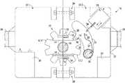
- reference numeral 10refers generally to an anti-theft device for a vehicle which is intended to prevent vehicle theft.
- the device 10which may also be referred to as a drivetrain or driveshaft lock is fitted to a drivetrain of the vehicle, downstream of or after a power plant which is drivingly connected to the drivetrain.
- the anti-theft device 10is mounted adjacent to a driveshaft of the drivetrain downstream of a vehicle transmission or gearbox. It will be appreciated, however, that the device 10 may be accommodated wholly, or at least in part, within the vehicle transmission. Accordingly, the device 10 may be incorporated into a gearbox or differential of the vehicle.
- the Applicantbelieves that conventional alarm systems which are configured to immobilise a vehicle by interrupting power to electrical components of either the ignition or starter are easier to bypass than when a physical, concealed lock has been applied to the drivetrain of the vehicle, specifically to a latter portion thereof.
- a physical, concealed lockhas been applied to the drivetrain of the vehicle, specifically to a latter portion thereof.
- the present inventionaims to overcome this drawback.
- a drivetrain of the vehicleis provided with a toothed rotor or gear 12 which is mounted around a drive or prop shaft 13 of the vehicle, downstream of a clutch, for rotation together with the driveshaft 13 about a shaft axis.
- the anti-theft device 10is retrofitted to the vehicle.
- the scope of the inventionalso extends to an anti-theft device which is fitted upon assembly of the vehicle.
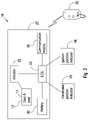
- the anti-theft device 10further includes an actuator 23 and an electronic control unit 22 which is communicatively linked to the actuator 23 .
- the actuator 23is in the form of an electrically operated linear actuator or solenoid having an extendable/retractable pin 24 or plunger.
- the pin 24is spring loaded and is configured to bear against a rear face of the locking pawl 17 in order to urge it into engagement with the gear 12 when the device 10 is locked or activated.
- a robust, secure, tamper-proof casing 27which is mounted to an underside of the vehicle around the driveshaft 13 , proximate a centre bearing support 39 (see FIG. 3 ) of the drivetrain by way of brackets 29 .
- the driveshaft 13effectively passes through the casing 27 , the casing 27 wrapping around the shaft.
- the casing 27comprises two halves or parts 27 . 1 , 27 . 2 which are secured together using obscured or concealed bolts and nuts 28 .
- Faces of adjacent teeth 20 of the gear 12 that define the spaces 19 between them and the head 18 of the pawl 17are purposefully shaped such that the head 18 cannot engage the gear 12 when the gear 12 is rotating above a threshold angular velocity or speed. This serves as an additional safety mechanism as engagement of the pawl 17 whilst the gear 12 is rotating at high speed could cause significant mechanical damage or failure of the components of the device 10 .
- the spring-loaded pin 24 of the solenoidwill ensure engagement of the pawl 17 with the gear 12 once the gear 12 rotates in any direction, in the event that the head 18 of the pawl 17 is misaligned with the spaces 19 between the teeth 20 of the gear 12 when the device 10 is locked.
- the anti-theft device 10is configured to be remotely activated or deactivated, i.e. primed to lock or unlocked.
- the device 10includes a communication module 34 (see FIG. 2 ).
- the module 34is in the form of wireless communication module which is communicatively linked to the electronic control unit 22 .
- the modulemay form part of the electronic control unit 22 , i.e. be integrated with the electronic control unit 22 .
- the device 10may be primed to lock in response to receipt of a control signal from the remote device 35 by the electronic control unit 22 , in which case the pawl 17 will lock as soon as the ignition is turned off and the handbrake is engaged.
- the locking pawl 17is moved to its open position, in which the gear 12 is free to rotate relative to the pawl 17 , through retraction of the pin 24 of the solenoid 23 which permits the pawl 17 to be returned to its open position in which it is spaced away from the gear 12 , due to the influence of the spring 31 , i.e. the device is unlocked.
- the electronic control unit 22is configured to activate/deactivate or lock/unlock the device 10 .
- the device 10is configured to lock automatically when the vehicle ignition is turned off and the handbrake is engaged.
- the pawl 17which engages the gear 12 under influence of the solenoid when in its locked position therefore prevents rotation of the driveshaft 13 which means the rear wheels of the vehicle cannot rotate. This effectively immobilises the vehicle. Even if a thief manages to start the vehicle, he won't be able to drive away because the driveshaft 13 is fixed or locked in position by the pawl 17 .
- the device 10is also effective against towing as the front wheels are generally suspended to tow a vehicle which means the rear wheels need to be able to rotate to tow the vehicle. In this instance, the vehicle cannot be towed away whilst the device 10 is engaged because the rear wheels cannot rotate freely.
- FIG. 4in order to prevent unauthorised disconnection of the driveshaft 13 , conventional fasteners used to secure the driveshaft 13 to a differential unit 36 , are replaced with a number of specialised keyed lock nuts and bolts 37 .
- the boltshave a specialised head 38 which defines an unusual socket which cannot be accessed or engaged using a normal spanner.
- the nutshave a similar head which necessitates the use of a purpose-built key in order to tighten or loosen the nuts. In this way unauthorised disconnection of the prop shaft from the differential is prevented.
- the same lock nuts and boltsmay be used to secure the casing 27 as well as central and fore linkages of the driveshaft 13 with the remainder of the drivetrain. Unauthorised disconnection of the prop shaft downstream of the device 10 would effectively bypass the device 10 because it would free up rotation of the rear wheels of the vehicle which would allow towing.
- Electronic/electrical and automatic actuation of the actuator 23 in order to lock or unlock the device 10makes the device simple to use because it does not require manual manipulation to engage and disengage the locking member.
- the communication module 34enables remote control of the device 10 even when the owner is not in close proximity to the vehicle. For example, in the event that the vehicle has been stolen, the owner can still prime the device 10 to lock it as soon as the ignition has been turned off. Engagement of the locking pawl 17 whilst the vehicle is in motion is undesirable and dangerous.
- the tracking unit or GPS datacan be used as an input to the ECU 22 to establish whether or not the vehicle is in motion.
- the device 10can be integrated with an existing vehicle alarm system so that it locks and unlocks together with the conventional alarm.
- the vehicle anti-theft device 10 in accordance with the inventionwill be a more effective vehicle theft deterrent than conventional anti-theft vehicle systems because it is difficult to bypass and fixates the entire driveshaft which immobilises the driven wheels of the vehicle and prevents towing.
- the first objective of a vehicle thiefis to gain entry to the vehicle cabin.
- a thiefwould still not be able to drive the vehicle or disable or disengage the locking member despite having gained entry to the vehicle cabin.
Landscapes
- Engineering & Computer Science (AREA)
- Mechanical Engineering (AREA)
- General Engineering & Computer Science (AREA)
- Human Computer Interaction (AREA)
- Radar, Positioning & Navigation (AREA)
- Remote Sensing (AREA)
- Chemical & Material Sciences (AREA)
- Combustion & Propulsion (AREA)
- Transportation (AREA)
- Lock And Its Accessories (AREA)
- Burglar Alarm Systems (AREA)
- Vehicle Interior And Exterior Ornaments, Soundproofing, And Insulation (AREA)
Abstract
Description
- a locking member which is mounted adjacent to the drivetrain, downstream of the power plant, and which is movable relative to the drivetrain between an open position in which a driveshaft or transmission of the drivetrain is permitted to move relative to the locking member and an engaged or locked position in which the locking member prevents displacement of the driveshaft or transmission relative to the locking member;
- an actuator which is configured to displace the locking member relative to the drivetrain from one of its open or locked positions to the other; and
- an electronic control unit which is communicatively linked to the actuator and is configured to receive a first signal indicative of whether or not power to the power plant is cut off and a second signal indicative of whether or not the drivetrain is in motion, wherein the electronic control unit is further configured to actuate the actuator in order to move the locking member into its locked position provided that power to the power plant is cut off and the vehicle is not in motion or is moving at a rate which is below a predetermined threshold value.
- retrofitting a toothed rotor to a driveshaft of the drivetrain of the vehicle for rotation together with the driveshaft;
- mounting a locking member to the vehicle in close proximity to the rotor, the locking member being movable by way of an actuator coupled to an electronic control unit between a locked position in which it engages the rotor and prevents rotation thereof and an open position in which the rotor is permitted to rotate freely;
- at least partially enclosing the rotor and locking member with a casing in order to prevent tampering;
- coupling a handbrake of the vehicle as input to the electronic control unit of the device; and
- coupling an ignition switch of the vehicle as input to the electronic control unit of the device, wherein the electronic control unit is configured to actuate the actuator in order to move the locking member into its locked position when the ignition switch is turned off and the handbrake is engaged.
- providing an anti-theft device as described above fitted to a drivetrain of the vehicle; and
- automatically engaging or activating the device by moving the locking member into its locked position upon detecting, using the electronic control unit, that the handbrake or parkbrake of the vehicle is engaged and the ignition is turned off.
Claims (14)
Applications Claiming Priority (5)
| Application Number | Priority Date | Filing Date | Title |
|---|---|---|---|
| ZA201606093 | 2016-09-02 | ||
| ZA2016/06093 | 2016-09-02 | ||
| ZA2016/06693 | 2016-09-28 | ||
| ZA201606693 | 2016-09-28 | ||
| PCT/IB2016/057538WO2018042236A1 (en) | 2016-09-02 | 2016-12-12 | A vehicle anti-theft device |
Publications (2)
| Publication Number | Publication Date |
|---|---|
| US20190202398A1 US20190202398A1 (en) | 2019-07-04 |
| US11427153B2true US11427153B2 (en) | 2022-08-30 |
Family
ID=61301841
Family Applications (2)
| Application Number | Title | Priority Date | Filing Date |
|---|---|---|---|
| US16/329,974Active2037-12-21US11427153B2 (en) | 2016-09-02 | 2016-12-12 | Vehicle anti-theft device |
| US16/330,000Active2038-01-20US11235733B2 (en) | 2016-09-02 | 2017-06-13 | Remotely activated vehicle anti-theft device |
Family Applications After (1)
| Application Number | Title | Priority Date | Filing Date |
|---|---|---|---|
| US16/330,000Active2038-01-20US11235733B2 (en) | 2016-09-02 | 2017-06-13 | Remotely activated vehicle anti-theft device |
Country Status (9)
| Country | Link |
|---|---|
| US (2) | US11427153B2 (en) |
| EP (2) | EP3507144B1 (en) |
| KR (2) | KR20190056384A (en) |
| CN (2) | CN109996704A (en) |
| AU (2) | AU2016421657B2 (en) |
| CA (2) | CA3074343A1 (en) |
| ES (2) | ES2967757T3 (en) |
| WO (1) | WO2018042236A1 (en) |
| ZA (2) | ZA201801856B (en) |
Families Citing this family (13)
| Publication number | Priority date | Publication date | Assignee | Title |
|---|---|---|---|---|
| US11427153B2 (en)* | 2016-09-02 | 2022-08-30 | Hardcore Automotive Locking Technologies (PTY) Limited | Vehicle anti-theft device |
| AU2018430802B2 (en)* | 2018-07-05 | 2022-12-22 | Hardcore Automotive Locking Technologies (Pty) Ltd | A retro-fittable vehicle lock |
| CN113034750B (en)* | 2018-09-30 | 2023-01-13 | 北京骑胜科技有限公司 | Vehicle lock control method and device and computer readable storage medium |
| US11840292B2 (en)* | 2018-10-12 | 2023-12-12 | New Heights, Llc | Locking mechanism for self-propelled tandem axle trailer |
| US10507792B1 (en) | 2019-01-04 | 2019-12-17 | Mike Gordon | Locking boot for vehicle wheel |
| WO2020233535A1 (en)* | 2019-05-17 | 2020-11-26 | 北京嘀嘀无限科技发展有限公司 | Vehicle lock control device, method and vehicle |
| US12109975B2 (en)* | 2019-09-26 | 2024-10-08 | Steering Solutions Ip Holding Corporation | Lock mechanism for steering assist system |
| KR102114900B1 (en) | 2019-11-18 | 2020-05-25 | 주식회사 카모스 | Auto lock system for door of vehicle and its control method |
| CN110901586B (en)* | 2019-11-29 | 2021-12-17 | 东风商用车有限公司 | Commercial vehicle theft tracking and positioning system |
| GB2592602A (en)* | 2020-03-03 | 2021-09-08 | Airbus Operations Ltd | An aircraft parking brake |
| CN113561936B (en)* | 2021-08-13 | 2022-05-17 | 深圳羽衡科技有限公司 | Electric vehicle noninductive riding intelligent control equipment based on mobile phone APP |
| EP4512671A1 (en) | 2023-08-25 | 2025-02-26 | Mike Gordon | Locking boot for vehicle wheel |
| WO2025160639A1 (en)* | 2024-01-30 | 2025-08-07 | Tury Do Brasil Indústria E Comércio Ltda. | Methods for blocking and unblocking electronic accelerator |
Citations (45)
| Publication number | Priority date | Publication date | Assignee | Title |
|---|---|---|---|---|
| US1363676A (en) | 1920-05-27 | 1920-12-28 | Schwemmer August | Locking means for automobiles |
| US1476437A (en) | 1922-01-07 | 1923-12-04 | William T Barker | Shaft-locking means |
| US1668395A (en) | 1926-05-24 | 1928-05-01 | Arthur H Hough | Shaft lock for automobiles |
| US1687475A (en) | 1924-01-29 | 1928-10-09 | William R Sweet | Automobile lock |
| US2890581A (en)* | 1955-11-23 | 1959-06-16 | Gen Motors Corp | Transmission lock |
| US2992693A (en) | 1957-11-04 | 1961-07-18 | Harvey E F Peyton | Drive shaft lock for automotive vehicles |
| US5020344A (en) | 1983-09-26 | 1991-06-04 | Garcia Gervasio B | Automobile anti-theft device |
| US5714807A (en) | 1996-04-18 | 1998-02-03 | Albanes; Pedro | Anti-theft lock for automotive vehicles which locks an automatic transmission |
| US5828297A (en) | 1997-06-25 | 1998-10-27 | Cummins Engine Company, Inc. | Vehicle anti-theft system |
| US5827149A (en) | 1996-07-30 | 1998-10-27 | Hi-Lex Corporation | Electrically operated park lock for automatic transmission |
| US6095310A (en) | 1997-05-01 | 2000-08-01 | Gear Protection Ltd. | Gear lock |
| US6107937A (en)* | 1995-01-31 | 2000-08-22 | Canon Kabushiki Kaisha | Remote control system and method |
| US6124789A (en)* | 1999-04-26 | 2000-09-26 | Barr; William A. | Vehicle automatic transmission shift lever alarm system |
| US6125671A (en)* | 1996-11-13 | 2000-10-03 | Kabushiki Kaisha Tokai Rika Denki Seisakusho | Steering lock system |
| US6250433B1 (en)* | 1999-05-24 | 2001-06-26 | Case Corporation | Positive-locking vehicular parking brake |
| US6279713B1 (en)* | 2000-02-17 | 2001-08-28 | Visteon Global Technologies, Inc. | Parking pawl assembly |
| US20020100300A1 (en) | 2001-01-31 | 2002-08-01 | Rex Reeb | Automobile anti-theft system |
| US6513638B2 (en) | 1999-04-20 | 2003-02-04 | Volvo Car Corporation | Vehicle latch arrangement |
| US20030075391A1 (en) | 2001-09-05 | 2003-04-24 | Zf Sachs Ag | Emergency brake for a motor vehicle |
| US6589134B2 (en) | 2001-09-27 | 2003-07-08 | Delphi Technologies, Inc. | System with controller and method for controlling a park-interlock device in a vehicle |
| US20040107028A1 (en) | 2002-12-03 | 2004-06-03 | Catalano Anthony B. | Override protocol system for affording vehicle safety and for preventing hijacking |
| US20040201461A1 (en) | 2001-06-12 | 2004-10-14 | Donald Parker | Vehicle alarm and theft deterrent system |
| US6885290B2 (en) | 2001-10-30 | 2005-04-26 | Kabushiki Kaisha Moric | Antitheft device for vehicles |
| US20050155824A1 (en) | 2002-08-16 | 2005-07-21 | Serge Taba | Anti-theft vehicle system |
| DE102004060817A1 (en) | 2004-12-17 | 2006-03-16 | Daimlerchrysler Ag | Jamming mechanism for motorcar engine has drive module, which encloses steering lock device and drive whereby in region of engine one transmission bell housing connected with gear unit is arranged |
| US7161467B2 (en)* | 2002-02-15 | 2007-01-09 | Alps Electric. Co., Ltd. | Vehicle-mounted device communication controller |
| WO2008007371A2 (en) | 2006-07-11 | 2008-01-17 | Haim Shnider | Method an d apparatus for controlling operation of a vehicular system |
| US7462953B2 (en)* | 2004-10-28 | 2008-12-09 | Denso Corporation | Control system for engine starting |
| US7484613B2 (en) | 2005-08-19 | 2009-02-03 | Hyundai Motor Company | Parking brake apparatus for automatic transmission vehicle and method for controlling operation thereof |
| US20110193692A1 (en) | 2008-10-10 | 2011-08-11 | Fong Jian-Jhong | Anti-theft system for vehicle |
| US8006526B2 (en) | 2006-04-27 | 2011-08-30 | Stoneridge Control Devices, Inc. | Steering shaft lock actuator |
| US20120016558A1 (en)* | 2009-03-23 | 2012-01-19 | Koki Ueno | Antitheft device for vehicle |
| US20120041647A1 (en) | 2009-03-03 | 2012-02-16 | Volkswagen Ag | Method and device for controlling a vehicle movement capability and/or a closure device |
| KR20120076830A (en) | 2010-12-30 | 2012-07-10 | 주식회사 일흥 | Vehicle remote control system and method using voice or text via wirelees communication terminal |
| US8219289B2 (en) | 2006-09-01 | 2012-07-10 | Toyota Jidosha Kabushiki Kaisha | Vehicle control apparatus, vehicle control method, computer program for implementing same method, and data storage medium storing same computer program |
| US8275511B2 (en) | 2006-11-03 | 2012-09-25 | Continental Automotive Systems Us, Inc. | Cryptology calculation for remote entry devices |
| US8281681B2 (en) | 2007-01-23 | 2012-10-09 | Toyota Jidosha Kabushiki Kaisha | Shift-by-wire system |
| US20150148990A1 (en) | 2009-10-14 | 2015-05-28 | Dipam Patel | Mobile Telephone for Remote Operation |
| US9185550B2 (en) | 2010-10-29 | 2015-11-10 | Honda Motor Co., Ltd. | Vehicle wireless communication apparatus |
| US20150382160A1 (en) | 2014-06-25 | 2015-12-31 | Verizon Patent And Licensing Inc. | Alerts based on vehicle and device telematics |
| US9404563B2 (en)* | 2014-05-21 | 2016-08-02 | Toyota Jidosha Kabushiki Kaisha | Power transmitting system of a vehicle |
| US9421945B1 (en) | 2014-07-18 | 2016-08-23 | Randall H. SMATHERS | Vehicle anti-theft system |
| US9649999B1 (en) | 2015-04-28 | 2017-05-16 | Sprint Communications Company L.P. | Vehicle remote operations control |
| US20170334393A1 (en) | 2014-11-20 | 2017-11-23 | Zf Friedrichshafen Ag | Securing of a motor vehicle |
| US20190202398A1 (en)* | 2016-09-02 | 2019-07-04 | Hardcore Automotive Locking Technologies (Pty) Ltd | A vehicle anti-theft device |
Family Cites Families (6)
| Publication number | Priority date | Publication date | Assignee | Title |
|---|---|---|---|---|
| CA2618437A1 (en)* | 2005-08-15 | 2007-02-22 | Salomon Sydney Ohayon | Universal electronic immobilizing for a vehicle |
| JP5426857B2 (en)* | 2008-09-24 | 2014-02-26 | 株式会社東海理化電機製作所 | Key slot device for in-vehicle auxiliary key |
| GB2467378A (en)* | 2009-02-02 | 2010-08-04 | Gm Global Tech Operations Inc | Transmission with a lock that prevents accidental park pawl reengagement |
| WO2015103363A2 (en)* | 2014-01-04 | 2015-07-09 | Tieman Craig A | Wirelessly controlled vehicle hood lock |
| US9168893B1 (en)* | 2014-04-22 | 2015-10-27 | Ituran Usa | System, method, and appartus for remotely disabling or enabling a vehicle |
| GB2529817B (en)* | 2014-09-02 | 2020-09-23 | Geoffrey Nixon Robin | Key module |
- 2016
- 2016-12-12USUS16/329,974patent/US11427153B2/enactiveActive
- 2016-12-12CACA3074343Apatent/CA3074343A1/ennot_activeAbandoned
- 2016-12-12KRKR1020197009491Apatent/KR20190056384A/ennot_activeWithdrawn
- 2016-12-12CNCN201680090584.3Apatent/CN109996704A/enactivePending
- 2016-12-12ESES16915022Tpatent/ES2967757T3/enactiveActive
- 2016-12-12AUAU2016421657Apatent/AU2016421657B2/enactiveActive
- 2016-12-12WOPCT/IB2016/057538patent/WO2018042236A1/ennot_activeCeased
- 2016-12-12EPEP16915022.4Apatent/EP3507144B1/enactiveActive
- 2017
- 2017-06-13EPEP17845600.0Apatent/EP3507780B1/enactiveActive
- 2017-06-13CACA3074352Apatent/CA3074352A1/ennot_activeAbandoned
- 2017-06-13AUAU2017318623Apatent/AU2017318623B2/enactiveActive
- 2017-06-13ESES17845600Tpatent/ES2942269T3/enactiveActive
- 2017-06-13USUS16/330,000patent/US11235733B2/enactiveActive
- 2017-06-13KRKR1020197009492Apatent/KR20190061001A/ennot_activeCeased
- 2017-06-13CNCN201780068002.6Apatent/CN110024007A/enactivePending
- 2018
- 2018-03-20ZAZA2018/01856Apatent/ZA201801856B/enunknown
- 2018-03-20ZAZA2018/01855Apatent/ZA201801855B/enunknown
Patent Citations (45)
| Publication number | Priority date | Publication date | Assignee | Title |
|---|---|---|---|---|
| US1363676A (en) | 1920-05-27 | 1920-12-28 | Schwemmer August | Locking means for automobiles |
| US1476437A (en) | 1922-01-07 | 1923-12-04 | William T Barker | Shaft-locking means |
| US1687475A (en) | 1924-01-29 | 1928-10-09 | William R Sweet | Automobile lock |
| US1668395A (en) | 1926-05-24 | 1928-05-01 | Arthur H Hough | Shaft lock for automobiles |
| US2890581A (en)* | 1955-11-23 | 1959-06-16 | Gen Motors Corp | Transmission lock |
| US2992693A (en) | 1957-11-04 | 1961-07-18 | Harvey E F Peyton | Drive shaft lock for automotive vehicles |
| US5020344A (en) | 1983-09-26 | 1991-06-04 | Garcia Gervasio B | Automobile anti-theft device |
| US6107937A (en)* | 1995-01-31 | 2000-08-22 | Canon Kabushiki Kaisha | Remote control system and method |
| US5714807A (en) | 1996-04-18 | 1998-02-03 | Albanes; Pedro | Anti-theft lock for automotive vehicles which locks an automatic transmission |
| US5827149A (en) | 1996-07-30 | 1998-10-27 | Hi-Lex Corporation | Electrically operated park lock for automatic transmission |
| US6125671A (en)* | 1996-11-13 | 2000-10-03 | Kabushiki Kaisha Tokai Rika Denki Seisakusho | Steering lock system |
| US6095310A (en) | 1997-05-01 | 2000-08-01 | Gear Protection Ltd. | Gear lock |
| US5828297A (en) | 1997-06-25 | 1998-10-27 | Cummins Engine Company, Inc. | Vehicle anti-theft system |
| US6513638B2 (en) | 1999-04-20 | 2003-02-04 | Volvo Car Corporation | Vehicle latch arrangement |
| US6124789A (en)* | 1999-04-26 | 2000-09-26 | Barr; William A. | Vehicle automatic transmission shift lever alarm system |
| US6250433B1 (en)* | 1999-05-24 | 2001-06-26 | Case Corporation | Positive-locking vehicular parking brake |
| US6279713B1 (en)* | 2000-02-17 | 2001-08-28 | Visteon Global Technologies, Inc. | Parking pawl assembly |
| US20020100300A1 (en) | 2001-01-31 | 2002-08-01 | Rex Reeb | Automobile anti-theft system |
| US20040201461A1 (en) | 2001-06-12 | 2004-10-14 | Donald Parker | Vehicle alarm and theft deterrent system |
| US20030075391A1 (en) | 2001-09-05 | 2003-04-24 | Zf Sachs Ag | Emergency brake for a motor vehicle |
| US6589134B2 (en) | 2001-09-27 | 2003-07-08 | Delphi Technologies, Inc. | System with controller and method for controlling a park-interlock device in a vehicle |
| US6885290B2 (en) | 2001-10-30 | 2005-04-26 | Kabushiki Kaisha Moric | Antitheft device for vehicles |
| US7161467B2 (en)* | 2002-02-15 | 2007-01-09 | Alps Electric. Co., Ltd. | Vehicle-mounted device communication controller |
| US20050155824A1 (en) | 2002-08-16 | 2005-07-21 | Serge Taba | Anti-theft vehicle system |
| US20040107028A1 (en) | 2002-12-03 | 2004-06-03 | Catalano Anthony B. | Override protocol system for affording vehicle safety and for preventing hijacking |
| US7462953B2 (en)* | 2004-10-28 | 2008-12-09 | Denso Corporation | Control system for engine starting |
| DE102004060817A1 (en) | 2004-12-17 | 2006-03-16 | Daimlerchrysler Ag | Jamming mechanism for motorcar engine has drive module, which encloses steering lock device and drive whereby in region of engine one transmission bell housing connected with gear unit is arranged |
| US7484613B2 (en) | 2005-08-19 | 2009-02-03 | Hyundai Motor Company | Parking brake apparatus for automatic transmission vehicle and method for controlling operation thereof |
| US8006526B2 (en) | 2006-04-27 | 2011-08-30 | Stoneridge Control Devices, Inc. | Steering shaft lock actuator |
| WO2008007371A2 (en) | 2006-07-11 | 2008-01-17 | Haim Shnider | Method an d apparatus for controlling operation of a vehicular system |
| US8219289B2 (en) | 2006-09-01 | 2012-07-10 | Toyota Jidosha Kabushiki Kaisha | Vehicle control apparatus, vehicle control method, computer program for implementing same method, and data storage medium storing same computer program |
| US8275511B2 (en) | 2006-11-03 | 2012-09-25 | Continental Automotive Systems Us, Inc. | Cryptology calculation for remote entry devices |
| US8281681B2 (en) | 2007-01-23 | 2012-10-09 | Toyota Jidosha Kabushiki Kaisha | Shift-by-wire system |
| US20110193692A1 (en) | 2008-10-10 | 2011-08-11 | Fong Jian-Jhong | Anti-theft system for vehicle |
| US20120041647A1 (en) | 2009-03-03 | 2012-02-16 | Volkswagen Ag | Method and device for controlling a vehicle movement capability and/or a closure device |
| US20120016558A1 (en)* | 2009-03-23 | 2012-01-19 | Koki Ueno | Antitheft device for vehicle |
| US20150148990A1 (en) | 2009-10-14 | 2015-05-28 | Dipam Patel | Mobile Telephone for Remote Operation |
| US9185550B2 (en) | 2010-10-29 | 2015-11-10 | Honda Motor Co., Ltd. | Vehicle wireless communication apparatus |
| KR20120076830A (en) | 2010-12-30 | 2012-07-10 | 주식회사 일흥 | Vehicle remote control system and method using voice or text via wirelees communication terminal |
| US9404563B2 (en)* | 2014-05-21 | 2016-08-02 | Toyota Jidosha Kabushiki Kaisha | Power transmitting system of a vehicle |
| US20150382160A1 (en) | 2014-06-25 | 2015-12-31 | Verizon Patent And Licensing Inc. | Alerts based on vehicle and device telematics |
| US9421945B1 (en) | 2014-07-18 | 2016-08-23 | Randall H. SMATHERS | Vehicle anti-theft system |
| US20170334393A1 (en) | 2014-11-20 | 2017-11-23 | Zf Friedrichshafen Ag | Securing of a motor vehicle |
| US9649999B1 (en) | 2015-04-28 | 2017-05-16 | Sprint Communications Company L.P. | Vehicle remote operations control |
| US20190202398A1 (en)* | 2016-09-02 | 2019-07-04 | Hardcore Automotive Locking Technologies (Pty) Ltd | A vehicle anti-theft device |
Non-Patent Citations (8)
| Title |
|---|
| Extended Search Report for European Patent Application No. 16915022.4, dated Oct. 30, 2020, 8 pages. |
| International Preliminary Report on Patentability prepared by the U.S. Patent and Trademark Office dated Aug. 23, 2018, for International Application No. PCT/IB2016/057538. |
| International Preliminary Report on Patentability prepared by the U.S. Patent and Trademark Office dated Sep. 7, 2018, for International Application No. PCT/IB2017/053496 15 pages. |
| International Search Report and Written Opinion prepared by the U.S. Patent and Trademark office dated Aug. 16, 2017, for International Application No. PCT/IB2017/053496 16 pages. |
| International Search Report prepared by the U.S. Patent and Trademark Office dated Apr. 15, 2017, for International Application No. PCT/IB2016/057538. |
| Notice of Allowance for U.S. Appl. No. 16/330,000, dated Sep. 22, 2021 8 pages. |
| Official Action for U.S. Appl. No. 16/330,000, dated Mar. 12, 2021 51 pages. |
| Written Opinion prepared by the U.S. Patent and Trademark Office dated Apr. 15, 2017, for International Application No. PCT/IB2016/057538. |
Also Published As
| Publication number | Publication date |
|---|---|
| US20190202398A1 (en) | 2019-07-04 |
| US20190202403A1 (en) | 2019-07-04 |
| CA3074343A1 (en) | 2018-03-08 |
| CN109996704A (en) | 2019-07-09 |
| KR20190056384A (en) | 2019-05-24 |
| CN110024007A (en) | 2019-07-16 |
| EP3507780A4 (en) | 2020-07-01 |
| EP3507144B1 (en) | 2023-10-25 |
| AU2017318623B2 (en) | 2022-05-19 |
| CA3074352A1 (en) | 2018-03-08 |
| EP3507144A1 (en) | 2019-07-10 |
| AU2017318623A1 (en) | 2019-04-18 |
| US11235733B2 (en) | 2022-02-01 |
| EP3507780B1 (en) | 2023-01-25 |
| AU2016421657A1 (en) | 2019-04-18 |
| ZA201801855B (en) | 2019-04-24 |
| EP3507780A1 (en) | 2019-07-10 |
| ZA201801856B (en) | 2019-12-18 |
| ES2942269T3 (en) | 2023-05-31 |
| KR20190061001A (en) | 2019-06-04 |
| AU2016421657B2 (en) | 2023-06-01 |
| WO2018042236A1 (en) | 2018-03-08 |
| ES2967757T3 (en) | 2024-05-03 |
| EP3507144A4 (en) | 2020-12-02 |
Similar Documents
| Publication | Publication Date | Title |
|---|---|---|
| US11427153B2 (en) | Vehicle anti-theft device | |
| US20090158790A1 (en) | Vehicle Immobilization System | |
| WO2018042264A1 (en) | A remotely activated vehicle anti-theft device | |
| US20020100300A1 (en) | Automobile anti-theft system | |
| GB2023520A (en) | Vehicle Anti-Theft Locking Arrangement | |
| US10391974B2 (en) | Antitheft security system and method for a motor vehicle | |
| US4615355A (en) | Automobile anti-theft device | |
| US5495925A (en) | Anti-theft device for a motor vehicle | |
| WO2018042237A1 (en) | A vehicle anti-theft device | |
| US9487185B2 (en) | Vehicle alarm system | |
| EP2746121B1 (en) | Handbrake locking device | |
| US20140360597A1 (en) | Double security lockable hydraulic valve | |
| KR200249744Y1 (en) | Anti-theft Device | |
| WO2002014122A1 (en) | Vehicle anti theft device | |
| CN205075790U (en) | Vehicle anti -theft locking device | |
| EP3199432A1 (en) | A vehicle alarm system | |
| CA2125814A1 (en) | Meintech electronic disabler | |
| CZ7677U1 (en) | Mechanical safety device against vehicle theft | |
| DE202006005600U1 (en) | Security system for vehicle has extending locking struts to press onto the ground and lift some of the wheels |
Legal Events
| Date | Code | Title | Description |
|---|---|---|---|
| FEPP | Fee payment procedure | Free format text:ENTITY STATUS SET TO UNDISCOUNTED (ORIGINAL EVENT CODE: BIG.); ENTITY STATUS OF PATENT OWNER: SMALL ENTITY | |
| FEPP | Fee payment procedure | Free format text:ENTITY STATUS SET TO SMALL (ORIGINAL EVENT CODE: SMAL); ENTITY STATUS OF PATENT OWNER: SMALL ENTITY | |
| AS | Assignment | Owner name:HARDCORE AUTOMOTIVE LOCKING TECHNOLOGIES (PTY) LTD, SOUTH AFRICA Free format text:ASSIGNMENT OF ASSIGNORS INTEREST;ASSIGNOR:TALJAARD, PHILIPPUS PETRUS ERASMUS;REEL/FRAME:049060/0485 Effective date:20190430 Owner name:HARDCORE AUTOMOTIVE LOCKING TECHNOLOGIES (PTY) LTD Free format text:ASSIGNMENT OF ASSIGNORS INTEREST;ASSIGNOR:TALJAARD, PHILIPPUS PETRUS ERASMUS;REEL/FRAME:049060/0485 Effective date:20190430 | |
| STPP | Information on status: patent application and granting procedure in general | Free format text:DOCKETED NEW CASE - READY FOR EXAMINATION | |
| STPP | Information on status: patent application and granting procedure in general | Free format text:NON FINAL ACTION MAILED | |
| STPP | Information on status: patent application and granting procedure in general | Free format text:RESPONSE TO NON-FINAL OFFICE ACTION ENTERED AND FORWARDED TO EXAMINER | |
| STPP | Information on status: patent application and granting procedure in general | Free format text:NOTICE OF ALLOWANCE MAILED -- APPLICATION RECEIVED IN OFFICE OF PUBLICATIONS | |
| STPP | Information on status: patent application and granting procedure in general | Free format text:DOCKETED NEW CASE - READY FOR EXAMINATION | |
| STPP | Information on status: patent application and granting procedure in general | Free format text:AWAITING RESPONSE FOR INFORMALITY, FEE DEFICIENCY OR CRF ACTION | |
| STPP | Information on status: patent application and granting procedure in general | Free format text:NOTICE OF ALLOWANCE MAILED -- APPLICATION RECEIVED IN OFFICE OF PUBLICATIONS | |
| STPP | Information on status: patent application and granting procedure in general | Free format text:PUBLICATIONS -- ISSUE FEE PAYMENT VERIFIED | |
| STCF | Information on status: patent grant | Free format text:PATENTED CASE |