US11426285B2 - Truss glenoid augment - Google Patents
Truss glenoid augmentDownload PDFInfo
- Publication number
- US11426285B2 US11426285B2US16/990,155US202016990155AUS11426285B2US 11426285 B2US11426285 B2US 11426285B2US 202016990155 AUS202016990155 AUS 202016990155AUS 11426285 B2US11426285 B2US 11426285B2
- Authority
- US
- United States
- Prior art keywords
- bone
- glenoid
- facing surface
- set screw
- glenoid implant
- Prior art date
- Legal status (The legal status is an assumption and is not a legal conclusion. Google has not performed a legal analysis and makes no representation as to the accuracy of the status listed.)
- Active
Links
- 241001653121GlenoidesSpecies0.000titleclaimsabstractdescription114
- 239000007943implantSubstances0.000claimsabstractdescription64
- 210000004095humeral headAnatomy0.000claimsabstractdescription17
- 230000007704transitionEffects0.000claimsdescription6
- 210000000988bone and boneAnatomy0.000description26
- 230000003628erosive effectEffects0.000description9
- 230000008878couplingEffects0.000description8
- 238000010168coupling processMethods0.000description8
- 238000005859coupling reactionMethods0.000description8
- 238000000034methodMethods0.000description8
- 230000008859changeEffects0.000description7
- 239000000463materialSubstances0.000description7
- 230000003190augmentative effectEffects0.000description6
- 229910052751metalInorganic materials0.000description6
- 239000002184metalSubstances0.000description6
- 239000000919ceramicSubstances0.000description5
- RTAQQCXQSZGOHL-UHFFFAOYSA-NTitaniumChemical compound[Ti]RTAQQCXQSZGOHL-UHFFFAOYSA-N0.000description4
- 230000002093peripheral effectEffects0.000description4
- 229920000642polymerPolymers0.000description4
- 239000010936titaniumSubstances0.000description4
- 229910052719titaniumInorganic materials0.000description4
- 210000003484anatomyAnatomy0.000description3
- 238000011882arthroplastyMethods0.000description3
- 229920000249biocompatible polymerPolymers0.000description3
- 210000000323shoulder jointAnatomy0.000description3
- 239000004696Poly ether ether ketoneSubstances0.000description2
- 239000000853adhesiveSubstances0.000description2
- 230000001070adhesive effectEffects0.000description2
- 238000002513implantationMethods0.000description2
- 150000002739metalsChemical class0.000description2
- 239000004033plasticSubstances0.000description2
- 229920003023plasticPolymers0.000description2
- 229920002530polyetherether ketonePolymers0.000description2
- 239000004698PolyethyleneSubstances0.000description1
- 239000004699Ultra-high molecular weight polyethyleneSubstances0.000description1
- 230000008901benefitEffects0.000description1
- JUPQTSLXMOCDHR-UHFFFAOYSA-Nbenzene-1,4-diol;bis(4-fluorophenyl)methanoneChemical compoundOC1=CC=C(O)C=C1.C1=CC(F)=CC=C1C(=O)C1=CC=C(F)C=C1JUPQTSLXMOCDHR-UHFFFAOYSA-N0.000description1
- 239000004568cementSubstances0.000description1
- 230000000295complement effectEffects0.000description1
- 230000006835compressionEffects0.000description1
- 238000007906compressionMethods0.000description1
- 239000000945fillerSubstances0.000description1
- 230000013011matingEffects0.000description1
- 238000012986modificationMethods0.000description1
- 230000004048modificationEffects0.000description1
- -1polyethylenePolymers0.000description1
- 229920000573polyethylenePolymers0.000description1
- 230000008569processEffects0.000description1
- 230000003068static effectEffects0.000description1
- 229920000785ultra high molecular weight polyethylenePolymers0.000description1
- 239000011800void materialSubstances0.000description1
Images


Classifications
- A—HUMAN NECESSITIES
- A61—MEDICAL OR VETERINARY SCIENCE; HYGIENE
- A61F—FILTERS IMPLANTABLE INTO BLOOD VESSELS; PROSTHESES; DEVICES PROVIDING PATENCY TO, OR PREVENTING COLLAPSING OF, TUBULAR STRUCTURES OF THE BODY, e.g. STENTS; ORTHOPAEDIC, NURSING OR CONTRACEPTIVE DEVICES; FOMENTATION; TREATMENT OR PROTECTION OF EYES OR EARS; BANDAGES, DRESSINGS OR ABSORBENT PADS; FIRST-AID KITS
- A61F2/00—Filters implantable into blood vessels; Prostheses, i.e. artificial substitutes or replacements for parts of the body; Appliances for connecting them with the body; Devices providing patency to, or preventing collapsing of, tubular structures of the body, e.g. stents
- A61F2/02—Prostheses implantable into the body
- A61F2/30—Joints
- A61F2/40—Joints for shoulders
- A61F2/4081—Glenoid components, e.g. cups
- A—HUMAN NECESSITIES
- A61—MEDICAL OR VETERINARY SCIENCE; HYGIENE
- A61F—FILTERS IMPLANTABLE INTO BLOOD VESSELS; PROSTHESES; DEVICES PROVIDING PATENCY TO, OR PREVENTING COLLAPSING OF, TUBULAR STRUCTURES OF THE BODY, e.g. STENTS; ORTHOPAEDIC, NURSING OR CONTRACEPTIVE DEVICES; FOMENTATION; TREATMENT OR PROTECTION OF EYES OR EARS; BANDAGES, DRESSINGS OR ABSORBENT PADS; FIRST-AID KITS
- A61F2/00—Filters implantable into blood vessels; Prostheses, i.e. artificial substitutes or replacements for parts of the body; Appliances for connecting them with the body; Devices providing patency to, or preventing collapsing of, tubular structures of the body, e.g. stents
- A61F2/02—Prostheses implantable into the body
- A61F2/30—Joints
- A61F2/30721—Accessories
- A61F2/30734—Modular inserts, sleeves or augments, e.g. placed on proximal part of stem for fixation purposes or wedges for bridging a bone defect
- A—HUMAN NECESSITIES
- A61—MEDICAL OR VETERINARY SCIENCE; HYGIENE
- A61F—FILTERS IMPLANTABLE INTO BLOOD VESSELS; PROSTHESES; DEVICES PROVIDING PATENCY TO, OR PREVENTING COLLAPSING OF, TUBULAR STRUCTURES OF THE BODY, e.g. STENTS; ORTHOPAEDIC, NURSING OR CONTRACEPTIVE DEVICES; FOMENTATION; TREATMENT OR PROTECTION OF EYES OR EARS; BANDAGES, DRESSINGS OR ABSORBENT PADS; FIRST-AID KITS
- A61F2/00—Filters implantable into blood vessels; Prostheses, i.e. artificial substitutes or replacements for parts of the body; Appliances for connecting them with the body; Devices providing patency to, or preventing collapsing of, tubular structures of the body, e.g. stents
- A61F2/02—Prostheses implantable into the body
- A61F2/30—Joints
- A61F2/30721—Accessories
- A61F2/30749—Fixation appliances for connecting prostheses to the body
- A—HUMAN NECESSITIES
- A61—MEDICAL OR VETERINARY SCIENCE; HYGIENE
- A61F—FILTERS IMPLANTABLE INTO BLOOD VESSELS; PROSTHESES; DEVICES PROVIDING PATENCY TO, OR PREVENTING COLLAPSING OF, TUBULAR STRUCTURES OF THE BODY, e.g. STENTS; ORTHOPAEDIC, NURSING OR CONTRACEPTIVE DEVICES; FOMENTATION; TREATMENT OR PROTECTION OF EYES OR EARS; BANDAGES, DRESSINGS OR ABSORBENT PADS; FIRST-AID KITS
- A61F2/00—Filters implantable into blood vessels; Prostheses, i.e. artificial substitutes or replacements for parts of the body; Appliances for connecting them with the body; Devices providing patency to, or preventing collapsing of, tubular structures of the body, e.g. stents
- A61F2/02—Prostheses implantable into the body
- A61F2/30—Joints
- A61F2002/30001—Additional features of subject-matter classified in A61F2/28, A61F2/30 and subgroups thereof
- A61F2002/30108—Shapes
- A61F2002/3011—Cross-sections or two-dimensional shapes
- A61F2002/30112—Rounded shapes, e.g. with rounded corners
- A61F2002/30125—Rounded shapes, e.g. with rounded corners elliptical or oval
- A—HUMAN NECESSITIES
- A61—MEDICAL OR VETERINARY SCIENCE; HYGIENE
- A61F—FILTERS IMPLANTABLE INTO BLOOD VESSELS; PROSTHESES; DEVICES PROVIDING PATENCY TO, OR PREVENTING COLLAPSING OF, TUBULAR STRUCTURES OF THE BODY, e.g. STENTS; ORTHOPAEDIC, NURSING OR CONTRACEPTIVE DEVICES; FOMENTATION; TREATMENT OR PROTECTION OF EYES OR EARS; BANDAGES, DRESSINGS OR ABSORBENT PADS; FIRST-AID KITS
- A61F2/00—Filters implantable into blood vessels; Prostheses, i.e. artificial substitutes or replacements for parts of the body; Appliances for connecting them with the body; Devices providing patency to, or preventing collapsing of, tubular structures of the body, e.g. stents
- A61F2/02—Prostheses implantable into the body
- A61F2/30—Joints
- A61F2002/30001—Additional features of subject-matter classified in A61F2/28, A61F2/30 and subgroups thereof
- A61F2002/30316—The prosthesis having different structural features at different locations within the same prosthesis; Connections between prosthetic parts; Special structural features of bone or joint prostheses not otherwise provided for
- A61F2002/30329—Connections or couplings between prosthetic parts, e.g. between modular parts; Connecting elements
- A61F2002/30433—Connections or couplings between prosthetic parts, e.g. between modular parts; Connecting elements using additional screws, bolts, dowels, rivets or washers e.g. connecting screws
- A—HUMAN NECESSITIES
- A61—MEDICAL OR VETERINARY SCIENCE; HYGIENE
- A61F—FILTERS IMPLANTABLE INTO BLOOD VESSELS; PROSTHESES; DEVICES PROVIDING PATENCY TO, OR PREVENTING COLLAPSING OF, TUBULAR STRUCTURES OF THE BODY, e.g. STENTS; ORTHOPAEDIC, NURSING OR CONTRACEPTIVE DEVICES; FOMENTATION; TREATMENT OR PROTECTION OF EYES OR EARS; BANDAGES, DRESSINGS OR ABSORBENT PADS; FIRST-AID KITS
- A61F2/00—Filters implantable into blood vessels; Prostheses, i.e. artificial substitutes or replacements for parts of the body; Appliances for connecting them with the body; Devices providing patency to, or preventing collapsing of, tubular structures of the body, e.g. stents
- A61F2/02—Prostheses implantable into the body
- A61F2/30—Joints
- A61F2/30721—Accessories
- A61F2/30734—Modular inserts, sleeves or augments, e.g. placed on proximal part of stem for fixation purposes or wedges for bridging a bone defect
- A61F2002/30736—Augments or augmentation pieces, e.g. wedges or blocks for bridging a bone defect
- A—HUMAN NECESSITIES
- A61—MEDICAL OR VETERINARY SCIENCE; HYGIENE
- A61F—FILTERS IMPLANTABLE INTO BLOOD VESSELS; PROSTHESES; DEVICES PROVIDING PATENCY TO, OR PREVENTING COLLAPSING OF, TUBULAR STRUCTURES OF THE BODY, e.g. STENTS; ORTHOPAEDIC, NURSING OR CONTRACEPTIVE DEVICES; FOMENTATION; TREATMENT OR PROTECTION OF EYES OR EARS; BANDAGES, DRESSINGS OR ABSORBENT PADS; FIRST-AID KITS
- A61F2310/00—Prostheses classified in A61F2/28 or A61F2/30 - A61F2/44 being constructed from or coated with a particular material
- A61F2310/00005—The prosthesis being constructed from a particular material
- A61F2310/00011—Metals or alloys
- A61F2310/00023—Titanium or titanium-based alloys, e.g. Ti-Ni alloys
- A—HUMAN NECESSITIES
- A61—MEDICAL OR VETERINARY SCIENCE; HYGIENE
- A61F—FILTERS IMPLANTABLE INTO BLOOD VESSELS; PROSTHESES; DEVICES PROVIDING PATENCY TO, OR PREVENTING COLLAPSING OF, TUBULAR STRUCTURES OF THE BODY, e.g. STENTS; ORTHOPAEDIC, NURSING OR CONTRACEPTIVE DEVICES; FOMENTATION; TREATMENT OR PROTECTION OF EYES OR EARS; BANDAGES, DRESSINGS OR ABSORBENT PADS; FIRST-AID KITS
- A61F2310/00—Prostheses classified in A61F2/28 or A61F2/30 - A61F2/44 being constructed from or coated with a particular material
- A61F2310/00005—The prosthesis being constructed from a particular material
- A61F2310/00179—Ceramics or ceramic-like structures
Definitions
- Eccentric glenoid erosionmay occur in as many as 40% of shoulder arthroplasty candidates. Wear can present anteriorly, superiorly and posteriorly, with superior being most common in reverse shoulder arthroplasty (“RSA”) candidates, and posterior being most prevalent in total shoulder arthroplasty (“TSA”) candidates.
- RSAreverse shoulder arthroplasty
- TSAtotal shoulder arthroplasty
- the glenoid surfacemay take a biconcave shape (for example, a Walch B2 classification).
- the worn or degraded portion of the glenoidmay be referred to as the neoglenoid and the original portion of the glenoid may be referred to as the paleoglenoid.
- the neoglenoid surfacedevelops, it may begin to form a pseudo-articular surface that has cortical-type bone.
- Any glenoid implant that does not have a bone-contacting surface design (such as a bi-convex design) to match the corresponding surface(s) of a glenoid with eccentric glenoid erosionmay require removal of a relatively large amount of bone stock, including portions of the paleoglenoid, which may be undesirable.
- prostheses that are designed to fit the neoglenoidshould closely approximate the surface of both the neoglenoid and the paleoglenoid to be able to most effectively transfer stress to the bone in as close a manner as possible to the pre-operative state.
- the relative sizes and shapes of the paleoglenoid and the neoglenoidmay also change. It would thus be preferably to have an augmented glenoid implant that is capable of being implanted onto a glenoid with eccentric glenoid erosion to minimize the amount of native bone stock that needs to be removed. In addition, it would be preferable to have an augmented glenoid implant or implant system that performs well when implanted onto a native glenoid with eccentric glenoid erosion. It would additionally be preferable to have an augmented glenoid implant or implant system that is suitable for use in patients with different progressions of eccentric glenoid erosion. For example, glenoid implants with augments are typically only offered in one size, or a few discrete sizes. For such offerings, intraoperative adjustment of the implant is not possible, and a poor fit with the bone may result.
- a glenoid implant for replacing a native glenoidincludes an articulating surface configured to articulate with respect to a humeral head.
- a bone-facing surfacemay be opposite the articulating surface, the bone-facing surface having a first area configured to contact a paleoglenoid of the native glenoid.
- An augment portionmay be coupled to the bone-facing surface, the augment portion being configured to contact a neoglenoid of the native glenoid.
- the augment portionmay be transitionable between a first configuration in which the augment portion has a first convexity and a second configuration in which the augment portion has a second convexity different than the first convexity.
- the augment portionmay have a first end coupled to the bone-facing surface, and a second free end, the second free end being movable with respect to the bone-facing surface.
- the augment portionmay include a plurality of beams, each beam having a first end coupled to the bone-facing surface, and a second end coupled to a rim, the rim connecting the second ends of the beams.
- the rimmay include two terminal ends coupled to the bone-facing surface.
- the plurality of beamsmay include three beams.
- the rimmay have a contour that matches a contour of a posterior perimeter of the bone-facing surface.
- a plurality of fastener aperturesmay be in the bone-facing surface, each fastener aperture configured to receive a fastener therethrough. At least one of the fastener apertures may have a longitudinal axis that extends between two adjacent beams of the plurality of beams.
- a set screw aperturemay be positioned in the bone-facing surface, the set screw aperture configured to receive a set screw therethrough.
- the set screw aperturemay have a longitudinal axis that aligns with a corresponding one of the plurality of beams.
- the glenoid implantmay include the set screw.
- the set screwmay have threads, and the set screw aperture may have corresponding threads.
- the set screwis configured to be advanced through the set screw aperture so that a leading end of the set screw contacts the corresponding one of the plurality of beams.
- the first ends of the plurality of beamsmay be positioned along a transition line.
- the bone-facing surfacemay have a second area configured to be spaced away from the paleoglenoid of the native glenoid, the first area and the second area of the bone-facing surface being separated by the transition line.
- the glenoid implantmay include a base and an articulation portion adapted to couple to the base.
- the bone-facing surfacemay be positioned on the base, and the articulating surface may be positioned on the articulation portion.
- a method of implanting a glenoid implant onto a native glenoid of a patientmay include transitioning an augment portion from a first configuration in which the augment portion has a first convexity to a second configuration in which the augment portion has a second convexity different than the first convexity.
- the augment portionmay be coupled to a bone-facing surface of the glenoid implant.
- the glenoid implantmay be fixed to the native glenoid so that the augment portion confronts a neoglenoid of the native glenoid while in the second configuration, and a first area of the bone-facing surface confronts a paleoglenoid of the native glenoid, and so that an articulating surface of the glenoid implant opposite the bone-facing surface is positioned to articulate with respect to a humeral head of the patient.
- the augment portionmay be transitioned from the first configuration to the second configuration prior to the glenoid implant being fixed to the native glenoid.
- the augment portionmay be transitioned from the first configuration to the second configuration while the glenoid implant is at least partially fixed to the native glenoid.
- Transitioning the augment portion from the first configuration to the second configurationmay include driving a set screw through a set screw aperture in the bone-facing surface until a tip of the set screw contacts a first beam of the augment portion causing the augment portion to at least partially move away from the bone-facing surface of the glenoid implant.
- the augment portionmay include peripheral beams and a rim, the first beam being positioned between the peripheral beams, the first beam and the peripheral beams all having first ends coupled to the bone-facing surface, and second ends coupled to the rim.
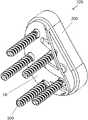
- FIGS. 1 and 2are perspective views of an augmented glenoid implant
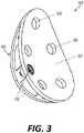
- FIG. 3is a perspective view of a base of the augmented glenoid implant of FIG. 1 .
- FIG. 4is an exploded perspective view of the base of FIG. 3 .
- FIG. 5is a perspective view of a bone-contacting surface of the base of FIG. 3 .
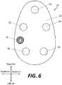
- FIG. 6is a plan view of a second surface of the base of FIG. 3 .
- FIG. 7is a plan view of the bone-contacting surface of the base of FIG. 3 .
- FIGS. 8-9are side views of the base of FIG. 3 .
- FIG. 10is a cross-section of the base of FIG. 3 .
- proximalmeans situated relatively close to the heart of the body and the term “distal” means situated relatively far from the heart.
- anteriormeans towards the front part of the body (or the face) and the term “posterior” means towards the rear of the body.
- medialmeans toward the midline of the body and the term “lateral” means away from the midline of the body.
- the terms “about,” “generally,” and “substantially”are intended to mean deviations from absolute are included within the scope of the term so modified.
- FIGS. 1 and 2are perspective views of a right glenoid implant 100 according to an aspect of the disclosure. It should be understood that a left glenoid implant may be provided that is substantially similar or identical to right glenoid implant 100 , although the left glenoid implant may be a substantially mirror image of the right glenoid implant 100 .
- FIG. 1is a perspective view of a lateral portion of the glenoid implant 100
- FIG. 2is a perspective view of a medial portion of the glenoid implant 100 .
- glenoid implant 100may include an insert or an articulating portion 200 adapted to articulate with respect to a native or prosthetic humeral head, a base 10 adapted to contact the glenoid and to receive the articulating portion 200 , and one or more fixation elements 300 such as screws to assist in fixing the base 10 to the glenoid.
- FIGS. 2-10illustrate various views of base 10 .
- Base 10may include a bone-facing surface 30 (best illustrated in FIGS. 5 and 7 ) and a second surface 20 opposite the bone-facing surface (best illustrated in FIGS. 3-4 and 6 ).
- the second surface 20is intended for receiving or otherwise coupling to articulating portion 200 , which in turn is intended to articulate with a corresponding humeral head of the shoulder joint, whether a native or prosthetic humeral head. In some embodiments, however, the second surface 20 may be adapted to directly articulate with the humeral head, without any additional intervening articulating portion.
- the bone-facing surface 30is intended for facing toward the patient's glenoid upon implantation, although it should be understood that some portions of bone-facing surface 30 may be in contact with the patient's bone, while other portions may not be in contact with the patient's bone, as described in greater detail below.
- An augment portion 40may extend generally medially from the bone-facing surface of base 10 .
- the bone-facing surface 30faces medially when implanted, while the second surface 20 faces laterally when implanted.
- the second surface 20may include a plurality of apertures 50 extending between the medial and lateral faces of the second surface 20 for receiving fasteners 300 therethrough, such as bone screws, to help secure the base 10 to the patient's glenoid.
- the second surface 20may also include a set screw aperture 60 extending between the medial and lateral faces of the second surface 20 for receiving a set screw 70 therethrough.
- the set screw 70may be advanced within the set screw aperture 60 , and as the leading end of the set screw 70 pushes against the augment portion 40 while being advanced, the augment portion 40 may expand, bow outwardly (e.g. increase in convexity), or otherwise change shape, as is described in greater detail below.
- the second surface 20 of glenoid implant 10may be generally ovoid or egg-shaped, with a relatively narrow superior end and a relatively wide inferior end, which may generally match the shape of a typical native glenoid and the shape of the articulating portion 200 , although the articulating portion may have a larger perimeter than base 10 .
- the second surface 20may also have a concavity (best illustrated in FIGS. 3-4 ) that matches a concavity of articulation portion 200 , which in turn is meant to assist in allowing the humeral head to articulate with respect to the glenoid implant 100 .
- second surface 20includes a first superior aperture 50 substantially centered along the anterior-posterior direction of the base 10 , a first pair of two apertures 50 on the anterior and posterior sides of the second surface 20 generally near a superior-inferior mid-point of the base 10 , and a second pair of two apertures 50 on the inferior end of the second surface 20 .
- One of the second pair of two apertures 50may be closer to the posterior side of the base 10
- the other of the second pair of two apertures 50may be closer to the anterior side of the base 10 .
- apertures 50a total of five apertures in an exaggerated pentagon shape may be provided, with each aperture 50 adapted to receive a fastener 300 therethrough to help secure the base 10 to the native glenoid.
- this arrangement of aperturesis merely exemplary. Additional configurations of these apertures 50 may be provided without departing from the scope of the disclosure. For example, fewer than five apertures 50 may be provided, or more than five apertures 50 may be provided. Further, the apertures 50 may be positioned in different areas than those shown.
- the second surface 20is formed of a biocompatible metal, such as titanium, although in some instances it may be suitable to form the second surface 20 from a biocompatible polymer or ceramic, such as any of those described below in connection with articulation surface 200 .
- a biocompatible metalsuch as titanium
- second surface 20is being used to directly articulate with the humeral head, it may be preferable to form the second surface 20 of any such biocompatible polymer or ceramic.
- the bone-facing surface 30may have the same ovoid shape as the second surface 20 , as the bone-facing surface 30 and the second surface 20 may be opposite sides of the same structure. However, whereas second surface 20 may have a concave surface, the bone-facing surface 30 preferably has as convex surface with a first convexity. As best shown in FIG. 7 , the bone-facing surface 30 may be conceptually split into two components, including a first area 32 and a second area 34 . An imaginary line 36 may be drawn along the beams 42 of the augment portion 40 (described in greater detail below) where the beams 42 couple to the bone-facing surface 30 .
- This imaginary line 36may effectively divide the bone-facing surface 30 , with the first area 32 being intended to be in contact with bone, specifically the paleoglenoid, and the second area 34 intended to be spaced away from the bone via the augment portion 40 .
- the trajectory of the imaginary line 36may generally correspond to a typical trajectory of the line dividing the paleoglenoid from the neoglenoid in a native glenoid with eccentric glenoid erosion.
- the bone-facing surface 30may also be made from a biocompatible metal, such as titanium.
- the bone-facing surface 30may include additional materials such as a porous metal, such as porous titanium, to increase bone ingrowth into the bone-facing surface 30 , although such an additional feature is not necessary.
- the second surface 20 and bone-facing surface 30are two opposite faces of an integral structure that are spaced apart from one another by a thickness.
- any of the apertures 50 that are positioned within the second area 34 of bone-facing surface 30preferably have a longitudinal axis that extends between adjacent ones of the beams 42 .
- the one or more set screw apertures 60preferably have a longitudinal axis that aligns with a corresponding beam.
- augment portion 40may be coupled to bone-facing surface 30 of base 10 .
- augment portion 40has a skeletonized or truss-like frame that allows the augment portion 40 to be expanded and/or to bow outwardly and/or to change convexity.
- the augment portion 40includes a plurality of beams 42 spaced apart from one another having a first end coupled to the bone-facing surface 30 .
- the second end of each beam 42may be coupled to a rim 44 of the augment portion 40 .
- the rim 44may be relatively narrow or thin compared to one or more of the beams 42 , and may have a contour that generally corresponds to a contour of the posterior perimeter of the bone-facing surface 30 of base 10 .
- the beams 42 and/or rim 44may have any suitable thickness, including for example between about 3 mm and about 7 mm.
- the rim 44may be substantially continuous and connect the second ends of all of the beams 42 .
- three beams 42connect the rim 44 to the bone-facing surface 30 , with a central one of the beams 42 being wider or thicker than the peripheral beams 42 on either side of the central beam 42 .
- the terminal ends of the rim 44 that couple to the bone-facing surface 30may also be thought of as beams that are narrower than the other three beams 42 , in which case base 10 may be thought of as having five beams. In any event, it should be understood that more or fewer beams 42 may be provided.
- the augment portion 40may be integrally formed with the bone-contacting surface 30 , and may be formed of any desirable material including biocompatible metals, such as titanium. However, in other embodiments, the augment portion 40 may be formed separately from the remainder of base 10 , and then coupled by any suitable fashion, including for example adhesives. In some instances, the augment portion 40 may be formed of a different material than the remainder of the base 10 , such as a biocompatible polymer or ceramic, and in other cases the augment portion 40 may be formed of the same material as the remainder of the base 10 . In some embodiments, the beams 42 may be omitted. For example, if the augment portion 40 is formed of metal, it may be preferable to include the beams 42 as shown to assist in the augment portion 40 changing shape.
- the augment portion 40is formed of a polymer or plastic, it may be preferable to remove beams 42 , and instead only include rim 44 (including the two terminal ends of the rim 44 coupled to the bone-facing surface 30 ). Because a polymer or plastic may be significantly more flexible than typical metals, the augment portion 40 may suitably change shape and flex even if beams 42 are removed.
- each beam 42(and the terminal ends of the rim 44 ) may be movably coupled to the bone-contacting surface 30 to allow the second ends of the beams 42 (and the portions of rim 44 other than the terminal ends) to change position and/or shape relative to the bone-contacting surface 30 .
- the first ends of each beam 42(and the terminal ends of the rim 44 ) are hingedly coupled to the bone-contacting surface 30 , such as via a living hinge.
- the augment portion 40may be forced to expand as described in greater detail below.
- FIGS. 8 and 9illustrate anterior and posterior side views, respectively, of base 10
- FIG. 10illustrates a cross-section of the base taken along a plane orthogonal to the medial-lateral direction, with a view of the posterior side of the base 10
- FIGS. 8-10all illustrate augment portion 40 having been extended or expanded via set screw 70 .
- the set screw aperture 60may include a general cylindrical extension 38 extending from the bone-facing surface 30 adjacent the set screw aperture 60 in a medial direction.
- a longitudinal axis of the set screw aperture 60may be aligned with one of the beams 42 , including the wider centrally located beam 42 , as shown in FIGS. 9-10 .
- the cylindrical extension 38may include a mating feature such as threads, to assist in advancing the set screw 70 toward or away from the augment portion 40 .
- set screw 70includes a shaft and a head.
- the shaft of set screw 70may be entirely threaded, or partially threaded (e.g. a leading end may be unthreaded, and a trailing end adjacent the head may be threaded).
- a leading end or tip of the set screw 70may contact one of the beams 42 (and/or portions of adjacent rim 44 ) to push the augment portion 40 away from the bone-facing surface 30 .
- the head of set screw 70 and the set screw aperture 60may be correspondingly shaped so that, when the set screw 70 is received within the set screw aperture 60 , the head of the set screw 70 does not extend above the second surface 20 of the glenoid implant 10 , so as to avoid disrupting coupling of the articulation portion 200 to the base 10 , or in other embodiments where second surface 20 directly articulates with the humeral head, to avoid disrupting articulation between the humeral head and the second surface 20 of the base 10 .
- the illustrated embodimentincludes a single set screw 70 , in other embodiments, additional set screws may be provided (along with additional set screw apertures) so that force may be applied on other ones of the beams 42 to further control the shape and contours of the augment portion 40 .
- the articulating portion 200may have a generally ovoid shape similar to that of base 10 .
- articulating portion 200is formed of a biocompatible ceramic or polymer, such as polyethylene (including ultra-high molecular weight polyethylene) or polyether ether ketone (“PEEK”).
- articulating portion 200may include an articulating surface (shown in FIG. 1 ) intended to directly articulate with the humeral head of a patient, whether native or prosthetic.
- Articulating portion 200may include a second surface opposite the articulating surface (shown in FIG. 2 ) that is adapted to face the glenoid and to couple to base 10 .
- any suitable coupling featuremay be provided to couple the articulating portion 200 to the base 10 .
- articulating portion 200may be snap-fit or press-fit onto the base 10 .
- the articulating portion 200maybe coupled to the base 10 via adhesives, such as cement, or any other suitable modality.
- the perimeter of articulating portion 200may be slightly greater than that of base 10 so that there is some amount of overhang between the articulating portion 200 and the base 10 , although in other embodiments the perimeters may be substantially the same.
- the articulation portion 200may be omitted, and instead the second surface of the base 10 may be used to directly articulate with the humeral head.
- the base 10may be formed of different materials so that the surface that articulates with the humeral head is formed of a polymer or ceramic, and the base 10 may be thicker than shown in the drawings.
- a patient's shoulder joint, and particularly the native glenoidmay be accessed by any suitable method.
- the patient's glenoidmay require preparation prior to the implantation of implant 100 .
- a surgical robot with an associated cutting tool and/or an associated computermay be programmed to ream or otherwise prepare the surface(s) of the glenoid to accept glenoid implant 100 .
- any desired preparation of the glenoidmay be performed manually, or via a combination of manual and automated and/or robotic tools.
- the set screw 70may be advanced through set screw aperture 60 and the augment portion 40 expanded or re-configured to increase the convexity and/or the spacing of the rim 44 from the bone-facing surface 30 , and the glenoid may be prepared to substantially match (or complement) the expanded configuration of the augment portion 40 .
- the augment portion 40may be intraoperatively adjusted to match the glenoid surface (such as the prepared glenoid surface), with the set screw 70 allowing for fine-tuning of the shape of the augment portion 40 to best match the patient's glenoid.
- the base 10may be placed against the native glenoid, with the first area 32 of the bone-facing surface 30 confronting the paleoglenoid, and the augment portion 40 confronting the neoglenoid.
- the set screw 70may be advanced to expand or re-configure the shape and/or convexity of the augment portion 40 (also referred to as expanding the augment portion 40 ) until the augment portion 40 has a convexity and/or shape that suitably complements the concavity and/or shape of the neoglenoid.
- Such intraoperative adjustmentmay be performed prior to coupling the base 10 to the glenoid, or after partially coupling the base 10 to the glenoid.
- the base 10may be loosely placed against the glenoid (e g manually or with an associated holding tool) and the augment portion 40 may be expanded prior to fastening the base 10 to the bone with fasteners 300 , such as bone screws.
- fasteners 300such as bone screws
- one or more fasteners 300such as bone screws
- the set screw 70may be used to expand the augment portion 40 until the user is satisfied that the shape of the augment portion 40 desirably complements the shape of the neoglenoid.
- bone screws 300 that have already been fastened to the bonemay be further secured and/or tightened, and/or additional bone screws may be used to fasten the base 10 to the bone through apertures 50 not already occupied by a bone screw 300 .
- the set screw 70is preferably coupled to the set screw aperture 60 and/or cylindrical extension 38 so that the set screw 70 will not change position relative to the base 10 as a result of normal forces, including normal use of the shoulder joint, or even via the forces resulting from bone screws 300 coupling the base 10 to the glenoid.
- any fasteners 300 that pass through apertures 60preferably do not protrude above the second surface 20 once in their final positions, so as to avoid interference with either the coupling of articulation portion 200 , or with a humeral head articulating directly against the second surface 20 .
- Thismay be achieved, similar to set screw aperture 60 , by providing a countersink or other similar feature in the apertures 50 .
- one or more of the fasteners 300may be locking screws, which may help reduce augment compression forces.
- a single set screw 70is described above as being adjusted to increase or decrease the amount of expansion or convexity of augment portion 40 , it may be desirable to provide a plurality of set screws 70 of different lengths. By having available a plurality of set screws 70 of different lengths, it may be easier to achieve the desired level of expansion of augment portion 40 while minimizing the likelihood that the set screw 70 will protrude beyond the second surface 20 of base 10 .
- the first area 32 of base 10may be coupled to the paleoglenoid of the patient via fasteners 300 , although the fasteners may be less-than-fully tightened.
- the augment portion 40may be adjusted to the desired size using set screw 70 , and the articulation of the humeral head may be tested against the base 10 after attaching the articulation portion 200 to the base 10 . If the size of the augment portion 40 needs to be adjusted, the articulation portion 200 may be removed, and the set screw 70 adjusted (or replaced with a different length set screw) to change the size and/or shape of the augment portion 40 . Trialing may be completed again, and the process may be repeated until the size and/or shape of the augment portion 40 is satisfactory.
- additional fasteners 300may be inserted through the base 10 and into the neoglenoid, and any fasteners 300 already in the paleoglenoid may be further tightened if necessary. With all of the desired fasteners 300 coupling the base 10 to the glenoid, the articulation portion 200 may be coupled to the base 10 , completing the implant procedure.
- the proceduremay be completed, for example by closing the access that was previously created.
- one or more bone graft materials and/or bone void filler materialsmay be placed to fill some of the open space between the augment portion 40 and the second area 34 of the bone-facing surface 30 .
- glenoid implant 100allows for a single implant size to be used for a patients with a variety of anatomies. Whereas prior augmented glenoid implants may have included discrete implants of different sizes with the hope that one of the implant sizes would best fit a particular patient, glenoid implant 100 , and particularly the base 10 thereof, is intraoperatively adjustable in infinitely small increments to provide a large range of sizes of the augment portion 40 to fit most or all patients.
- the first area 32 of bone-facing surface 30may have a static shape and convexity, while the augment portion 40 may have a variable shape and convexity.
- the augment portion 40may be expanded to a relatively large amount to match that patient's particular anatomy.
- the augment portion 40may not need to be expanded at all, or may only need to be minimally expanded, to match that patient's particular anatomy.
- a single design for glenoid implant 100would allow for both patients to be treated, without the need for multiple glenoid implants being provided in a kit of different discrete sizes.
Landscapes
- Health & Medical Sciences (AREA)
- Orthopedic Medicine & Surgery (AREA)
- Cardiology (AREA)
- Oral & Maxillofacial Surgery (AREA)
- Transplantation (AREA)
- Engineering & Computer Science (AREA)
- Biomedical Technology (AREA)
- Heart & Thoracic Surgery (AREA)
- Vascular Medicine (AREA)
- Life Sciences & Earth Sciences (AREA)
- Animal Behavior & Ethology (AREA)
- General Health & Medical Sciences (AREA)
- Public Health (AREA)
- Veterinary Medicine (AREA)
- Prostheses (AREA)
Abstract
Description
Claims (16)
Priority Applications (1)
| Application Number | Priority Date | Filing Date | Title |
|---|---|---|---|
| US16/990,155US11426285B2 (en) | 2019-09-05 | 2020-08-11 | Truss glenoid augment |
Applications Claiming Priority (2)
| Application Number | Priority Date | Filing Date | Title |
|---|---|---|---|
| US201962896057P | 2019-09-05 | 2019-09-05 | |
| US16/990,155US11426285B2 (en) | 2019-09-05 | 2020-08-11 | Truss glenoid augment |
Publications (2)
| Publication Number | Publication Date |
|---|---|
| US20210068968A1 US20210068968A1 (en) | 2021-03-11 |
| US11426285B2true US11426285B2 (en) | 2022-08-30 |
Family
ID=72381025
Family Applications (1)
| Application Number | Title | Priority Date | Filing Date |
|---|---|---|---|
| US16/990,155ActiveUS11426285B2 (en) | 2019-09-05 | 2020-08-11 | Truss glenoid augment |
Country Status (3)
| Country | Link |
|---|---|
| US (1) | US11426285B2 (en) |
| EP (1) | EP3788990B1 (en) |
| AU (1) | AU2020223782A1 (en) |
Families Citing this family (1)
| Publication number | Priority date | Publication date | Assignee | Title |
|---|---|---|---|---|
| EP3911281A1 (en)* | 2019-01-15 | 2021-11-24 | Biopoly, Llc | Implant systems for repair of a glenoid cavity |
Citations (68)
| Publication number | Priority date | Publication date | Assignee | Title |
|---|---|---|---|---|
| US3559514A (en) | 1968-06-17 | 1971-02-02 | Russell Brownfield | Reamers for electrical line conduits, and the like |
| US4828439A (en)* | 1987-05-15 | 1989-05-09 | Giannuzzi Louis | Screw anchor |
| US5203653A (en) | 1991-12-30 | 1993-04-20 | Pfizer Hospital Products Group, Inc. | Reamer for shaping bone sockets |
| US5591170A (en) | 1994-10-14 | 1997-01-07 | Genesis Orthopedics | Intramedullary bone cutting saw |
| US5800551A (en) | 1997-03-10 | 1998-09-01 | Biomet, Inc. | Apparatus and method for shoulder arthroplasty |
| US5919195A (en) | 1998-01-20 | 1999-07-06 | Johnson & Johnson Professional, Inc. | Oblong acetabular component instrumentation |
| US20030163135A1 (en) | 2002-02-22 | 2003-08-28 | Hathaway Ray W. | Orthopeadic reamer with see-through viewing windows |
| US20030220646A1 (en) | 2002-05-23 | 2003-11-27 | Thelen Sarah L. | Method and apparatus for reducing femoral fractures |
| US6699289B2 (en) | 2001-12-31 | 2004-03-02 | Depuy Orthopaedics, Inc. | Augmented glenoid component having an interrupted surface and associated method for securing the augmented glenoid component to a glenoid surface of a scapula |
| US20040097947A1 (en) | 2002-09-13 | 2004-05-20 | Wolford Todd A. | Othopaedic reamer driver for minimally invasive surgery |
| US20040133275A1 (en)* | 2000-03-27 | 2004-07-08 | Mansmann Kevin A. | Implants for replacing cartilage, with negatively-charged hydrogel surfaces and flexible matrix reinforcement |
| US20040236339A1 (en) | 2002-02-22 | 2004-11-25 | Pepper John R. | Long bone reaming apparatus and method |
| US20050159751A1 (en) | 2004-01-13 | 2005-07-21 | Berthusen Andrew H. | Variable angle orthopaedic reamer driver |
| US6949101B2 (en) | 2002-03-29 | 2005-09-27 | Depuy Orthopaedics, Inc. | Medical instrument for milling a curved path in bone and procedure |
| US20050234460A1 (en)* | 2004-02-13 | 2005-10-20 | Drew Miller | Soft tissue repair apparatus and method |
| US20060015110A1 (en) | 2004-07-15 | 2006-01-19 | Pepper John R | Cutting device |
| US20060058809A1 (en) | 2004-06-03 | 2006-03-16 | Zink Robert W | Method and apparatus for preparing a glenoid surface |
| US20060074421A1 (en)* | 2003-05-08 | 2006-04-06 | Bickley Barry T | Fixation augmentation device and related techniques |
| US20070038302A1 (en) | 2005-08-15 | 2007-02-15 | Biomet Manufacturing Corp. | Method and apparatus for the preparation of an inlaid glenoid |
| US20070038303A1 (en) | 2006-08-15 | 2007-02-15 | Ebi, L.P. | Foot/ankle implant and associated method |
| US20070093840A1 (en) | 2005-10-06 | 2007-04-26 | Pacelli Nicolas J | Flexible shaft |
| US20080021474A1 (en)* | 2006-02-07 | 2008-01-24 | Bonutti Peter M | Methods and devices for intracorporeal bonding of implants with thermal energy |
| US20080027441A1 (en)* | 2006-07-31 | 2008-01-31 | Lopez Mandi J | A soft tissue fixation device |
| US7473254B2 (en) | 2002-05-10 | 2009-01-06 | Precimed S.A. | Pivoting bone reamer for minimally invasive joint surgery |
| US7572259B2 (en) | 2002-09-16 | 2009-08-11 | Greatbatch Ltd. | Inset acetabular reamer coupling |
| US20090270863A1 (en) | 2008-04-28 | 2009-10-29 | Robin Maisonneuve | Manual glenoid reamer |
| US7637909B2 (en) | 2002-04-30 | 2009-12-29 | Greatbatch Medical S.A. | Reamer spindle for minimally invasive joint surgery |
| US7749227B2 (en) | 2003-04-28 | 2010-07-06 | Greatbatch Medical S.A. | Precision assembleable surgical tool handle with limited-play interconnect mechanism |
| US20100228352A1 (en) | 2009-03-05 | 2010-09-09 | Tomier, Inc. | Glenoid implant anchor post |
| US7803160B2 (en) | 2002-01-11 | 2010-09-28 | Waldemar Link Gmbh & Co. Kg | Surgical instrument for grinding the cotyloid cavity |
| US7819875B2 (en) | 2002-02-08 | 2010-10-26 | Gursharan Singh Chana | Surgical devices and methods of use |
| US20110004215A1 (en) | 2005-09-12 | 2011-01-06 | Bradley James P | Labrum retracting burr |
| US7892287B2 (en) | 2004-09-27 | 2011-02-22 | Depuy Products, Inc. | Glenoid augment and associated method |
| US7922769B2 (en) | 2004-09-27 | 2011-04-12 | Depuy Products, Inc. | Modular glenoid prosthesis and associated method |
| US7927335B2 (en) | 2004-09-27 | 2011-04-19 | Depuy Products, Inc. | Instrument for preparing an implant support surface and associated method |
| US7993408B2 (en) | 2008-02-12 | 2011-08-09 | Biomet Manufacturing Corp. | Acetabular cup having an adjustable modular augment |
| US20120109229A1 (en) | 2009-07-10 | 2012-05-03 | Milux Holdind Sa | Hip joint instrument and method |
| US20120123419A1 (en) | 2010-11-08 | 2012-05-17 | Matthew Purdy | Orthopedic reamer for bone preparation, particularly glenoid preparation |
| US20120239042A1 (en) | 2011-03-18 | 2012-09-20 | Depuy Products, Inc. | Combination Reamer/Drill Bit for Shoulder Arthoplasty |
| US20130053891A1 (en)* | 2011-08-31 | 2013-02-28 | Depuy Spine, Inc. | Revisable orthopedic anchor and methods of use |
| US20130090737A1 (en)* | 2010-05-26 | 2013-04-11 | Topsfield Medical Gmbh | Implantable prostheses |
| US20130123930A1 (en)* | 2011-11-10 | 2013-05-16 | David Michael Burt | Arthroscopic total shoulder arthroplasty |
| US20130144393A1 (en) | 2009-12-14 | 2013-06-06 | Austin W. Mutchler | Shoulder prosthesis glenoid component |
| US8475460B1 (en) | 2010-02-23 | 2013-07-02 | Greatbatch Medical S.A. | Angled reamer spindle for minimally invasive hip replacement surgery |
| US8486076B2 (en) | 2011-01-28 | 2013-07-16 | DePuy Synthes Products, LLC | Oscillating rasp for use in an orthopaedic surgical procedure |
| US20130216297A1 (en)* | 2012-02-17 | 2013-08-22 | Newfrey Llc | Fastening apparatus |
| US8657833B2 (en) | 2010-03-05 | 2014-02-25 | Greatbatch Medical S.A. | Double offset surgical tool handle assembly to provide greater offset from the coronal plane |
| US8657834B2 (en) | 2010-03-05 | 2014-02-25 | Greatbatch Medical S.A. | Double offset surgical tool handle assembly having a locking linkage aligned along two different planes |
| US20140128983A1 (en)* | 2011-03-14 | 2014-05-08 | Topsfield Medical Gmbh | Implantable glenoid prostheses |
| US8721727B2 (en) | 2009-11-24 | 2014-05-13 | Tornier Sas | Glenoid component with offset center and associated methods |
| US8740907B2 (en) | 2002-06-10 | 2014-06-03 | Microport Orthopedics Holdings Inc. | Apparatus for and method of providing a hip replacement |
| US8771275B2 (en) | 2008-09-23 | 2014-07-08 | Ping Xie | Device for shaping object with a profile of at least a partial sphere |
| US20140277518A1 (en)* | 2013-03-15 | 2014-09-18 | The Cleveland Clinic Foundation | Prosthetic articulation surface mounting |
| US8864834B2 (en) | 2007-01-30 | 2014-10-21 | Tornier Sas | Method and apparatus for fitting a shoulder prosthesis |
| US9066730B2 (en) | 2005-02-21 | 2015-06-30 | Smith & Nephew Plc | Medical device |
| US9066731B2 (en) | 2007-12-21 | 2015-06-30 | Depuy International Limited | Instrument for removing tissue |
| US9078672B1 (en) | 2010-11-05 | 2015-07-14 | Greatbatch Medical S.A. | Carbon reamer handle |
| US9408652B2 (en) | 2010-04-27 | 2016-08-09 | Tornier Sas | Intra-articular joint replacement and method |
| US9414927B2 (en) | 2011-12-08 | 2016-08-16 | Imds Llc | Shoulder arthroplasty |
| US20160310285A1 (en) | 2015-04-24 | 2016-10-27 | Biomet Manufacturing, Llc | Patient-specific augmented glenoid systems and methods |
| US20180021050A1 (en)* | 2015-02-05 | 2018-01-25 | The Sydney Children's Hospitals Network (Randwick And Westmead) | Orthopaedic device for correction of deformities in a bone |
| US10028838B2 (en) | 2014-06-30 | 2018-07-24 | Tornier, Inc. | Augmented glenoid components and devices for implanting the same |
| EP3378444A1 (en) | 2017-03-22 | 2018-09-26 | Stryker European Holdings I, LLC | Stemless metaphyseal humeral implant |
| US20180318110A1 (en)* | 2017-05-08 | 2018-11-08 | Depuy Ireland Unlimited Company | Trial acetabular liners |
| EP3403617A1 (en) | 2017-05-19 | 2018-11-21 | Tornier | Augment insert, shoulder prosthesis and kit comprising the augment insert |
| US20190151106A1 (en) | 2014-08-14 | 2019-05-23 | Biomet Manufacturing, Llc | Glenoid implant |
| US20210228372A1 (en)* | 2018-10-02 | 2021-07-29 | Tornier, Inc. | Modular humeral head |
| US20210401584A1 (en)* | 2018-10-02 | 2021-12-30 | Howmedia Osteonics Corp. | Shoulder prosthesis components and assemblies |
- 2020
- 2020-08-11USUS16/990,155patent/US11426285B2/enactiveActive
- 2020-08-28AUAU2020223782Apatent/AU2020223782A1/enactivePending
- 2020-09-04EPEP20194646.4Apatent/EP3788990B1/enactiveActive
Patent Citations (75)
| Publication number | Priority date | Publication date | Assignee | Title |
|---|---|---|---|---|
| US3559514A (en) | 1968-06-17 | 1971-02-02 | Russell Brownfield | Reamers for electrical line conduits, and the like |
| US4828439A (en)* | 1987-05-15 | 1989-05-09 | Giannuzzi Louis | Screw anchor |
| US5203653A (en) | 1991-12-30 | 1993-04-20 | Pfizer Hospital Products Group, Inc. | Reamer for shaping bone sockets |
| US5591170A (en) | 1994-10-14 | 1997-01-07 | Genesis Orthopedics | Intramedullary bone cutting saw |
| US5800551A (en) | 1997-03-10 | 1998-09-01 | Biomet, Inc. | Apparatus and method for shoulder arthroplasty |
| US5919195A (en) | 1998-01-20 | 1999-07-06 | Johnson & Johnson Professional, Inc. | Oblong acetabular component instrumentation |
| US20040133275A1 (en)* | 2000-03-27 | 2004-07-08 | Mansmann Kevin A. | Implants for replacing cartilage, with negatively-charged hydrogel surfaces and flexible matrix reinforcement |
| US6699289B2 (en) | 2001-12-31 | 2004-03-02 | Depuy Orthopaedics, Inc. | Augmented glenoid component having an interrupted surface and associated method for securing the augmented glenoid component to a glenoid surface of a scapula |
| US7803160B2 (en) | 2002-01-11 | 2010-09-28 | Waldemar Link Gmbh & Co. Kg | Surgical instrument for grinding the cotyloid cavity |
| US7819875B2 (en) | 2002-02-08 | 2010-10-26 | Gursharan Singh Chana | Surgical devices and methods of use |
| US8282639B2 (en) | 2002-02-08 | 2012-10-09 | Gusharan Chana | Surgical devices and methods of use |
| US20030163135A1 (en) | 2002-02-22 | 2003-08-28 | Hathaway Ray W. | Orthopeadic reamer with see-through viewing windows |
| US20040236339A1 (en) | 2002-02-22 | 2004-11-25 | Pepper John R. | Long bone reaming apparatus and method |
| US6949101B2 (en) | 2002-03-29 | 2005-09-27 | Depuy Orthopaedics, Inc. | Medical instrument for milling a curved path in bone and procedure |
| US7785329B2 (en) | 2002-04-30 | 2010-08-31 | Greatbatch Medical S.A. | Reamer spindle for minimally invasive joint surgery |
| US7780669B2 (en) | 2002-04-30 | 2010-08-24 | Greatbatch Medical S.A. | Reamer spindle for minimally invasive joint surgery |
| US7637909B2 (en) | 2002-04-30 | 2009-12-29 | Greatbatch Medical S.A. | Reamer spindle for minimally invasive joint surgery |
| US7473254B2 (en) | 2002-05-10 | 2009-01-06 | Precimed S.A. | Pivoting bone reamer for minimally invasive joint surgery |
| US20030220646A1 (en) | 2002-05-23 | 2003-11-27 | Thelen Sarah L. | Method and apparatus for reducing femoral fractures |
| US8740907B2 (en) | 2002-06-10 | 2014-06-03 | Microport Orthopedics Holdings Inc. | Apparatus for and method of providing a hip replacement |
| US7217271B2 (en) | 2002-09-13 | 2007-05-15 | Symmetry Medical, Inc. | Orthopaedic reamer driver for minimally invasive surgery |
| US20040097947A1 (en) | 2002-09-13 | 2004-05-20 | Wolford Todd A. | Othopaedic reamer driver for minimally invasive surgery |
| US7572259B2 (en) | 2002-09-16 | 2009-08-11 | Greatbatch Ltd. | Inset acetabular reamer coupling |
| US7749227B2 (en) | 2003-04-28 | 2010-07-06 | Greatbatch Medical S.A. | Precision assembleable surgical tool handle with limited-play interconnect mechanism |
| US20060074421A1 (en)* | 2003-05-08 | 2006-04-06 | Bickley Barry T | Fixation augmentation device and related techniques |
| US8052690B2 (en) | 2004-01-13 | 2011-11-08 | Symmetry Medical, Inc. | Variable angle orthopaedic reamer driver |
| US20050159751A1 (en) | 2004-01-13 | 2005-07-21 | Berthusen Andrew H. | Variable angle orthopaedic reamer driver |
| US7503921B2 (en) | 2004-01-13 | 2009-03-17 | Symmetry Medical, Inc. | Variable angle orthopaedic reamer driver |
| US20050234460A1 (en)* | 2004-02-13 | 2005-10-20 | Drew Miller | Soft tissue repair apparatus and method |
| US20060058809A1 (en) | 2004-06-03 | 2006-03-16 | Zink Robert W | Method and apparatus for preparing a glenoid surface |
| US20060015110A1 (en) | 2004-07-15 | 2006-01-19 | Pepper John R | Cutting device |
| US7927335B2 (en) | 2004-09-27 | 2011-04-19 | Depuy Products, Inc. | Instrument for preparing an implant support surface and associated method |
| US7892287B2 (en) | 2004-09-27 | 2011-02-22 | Depuy Products, Inc. | Glenoid augment and associated method |
| US7922769B2 (en) | 2004-09-27 | 2011-04-12 | Depuy Products, Inc. | Modular glenoid prosthesis and associated method |
| US9066730B2 (en) | 2005-02-21 | 2015-06-30 | Smith & Nephew Plc | Medical device |
| US20070038302A1 (en) | 2005-08-15 | 2007-02-15 | Biomet Manufacturing Corp. | Method and apparatus for the preparation of an inlaid glenoid |
| US20110004215A1 (en) | 2005-09-12 | 2011-01-06 | Bradley James P | Labrum retracting burr |
| US20070093840A1 (en) | 2005-10-06 | 2007-04-26 | Pacelli Nicolas J | Flexible shaft |
| US20080021474A1 (en)* | 2006-02-07 | 2008-01-24 | Bonutti Peter M | Methods and devices for intracorporeal bonding of implants with thermal energy |
| US20080027441A1 (en)* | 2006-07-31 | 2008-01-31 | Lopez Mandi J | A soft tissue fixation device |
| US20070038303A1 (en) | 2006-08-15 | 2007-02-15 | Ebi, L.P. | Foot/ankle implant and associated method |
| US8864834B2 (en) | 2007-01-30 | 2014-10-21 | Tornier Sas | Method and apparatus for fitting a shoulder prosthesis |
| US9066731B2 (en) | 2007-12-21 | 2015-06-30 | Depuy International Limited | Instrument for removing tissue |
| US7993408B2 (en) | 2008-02-12 | 2011-08-09 | Biomet Manufacturing Corp. | Acetabular cup having an adjustable modular augment |
| US20090270863A1 (en) | 2008-04-28 | 2009-10-29 | Robin Maisonneuve | Manual glenoid reamer |
| US8771275B2 (en) | 2008-09-23 | 2014-07-08 | Ping Xie | Device for shaping object with a profile of at least a partial sphere |
| US20100228352A1 (en) | 2009-03-05 | 2010-09-09 | Tomier, Inc. | Glenoid implant anchor post |
| US20120109229A1 (en) | 2009-07-10 | 2012-05-03 | Milux Holdind Sa | Hip joint instrument and method |
| US8721727B2 (en) | 2009-11-24 | 2014-05-13 | Tornier Sas | Glenoid component with offset center and associated methods |
| US20130144393A1 (en) | 2009-12-14 | 2013-06-06 | Austin W. Mutchler | Shoulder prosthesis glenoid component |
| US8475460B1 (en) | 2010-02-23 | 2013-07-02 | Greatbatch Medical S.A. | Angled reamer spindle for minimally invasive hip replacement surgery |
| US8480674B1 (en) | 2010-02-23 | 2013-07-09 | Greatbatch Medical S.A. | Angled reamer spindle for minimally invasive hip replacement surgery |
| US8657833B2 (en) | 2010-03-05 | 2014-02-25 | Greatbatch Medical S.A. | Double offset surgical tool handle assembly to provide greater offset from the coronal plane |
| US8657834B2 (en) | 2010-03-05 | 2014-02-25 | Greatbatch Medical S.A. | Double offset surgical tool handle assembly having a locking linkage aligned along two different planes |
| US9408652B2 (en) | 2010-04-27 | 2016-08-09 | Tornier Sas | Intra-articular joint replacement and method |
| US20130090737A1 (en)* | 2010-05-26 | 2013-04-11 | Topsfield Medical Gmbh | Implantable prostheses |
| US9078672B1 (en) | 2010-11-05 | 2015-07-14 | Greatbatch Medical S.A. | Carbon reamer handle |
| US20120123419A1 (en) | 2010-11-08 | 2012-05-17 | Matthew Purdy | Orthopedic reamer for bone preparation, particularly glenoid preparation |
| US8486076B2 (en) | 2011-01-28 | 2013-07-16 | DePuy Synthes Products, LLC | Oscillating rasp for use in an orthopaedic surgical procedure |
| US20140128983A1 (en)* | 2011-03-14 | 2014-05-08 | Topsfield Medical Gmbh | Implantable glenoid prostheses |
| US20120239042A1 (en) | 2011-03-18 | 2012-09-20 | Depuy Products, Inc. | Combination Reamer/Drill Bit for Shoulder Arthoplasty |
| US20130053891A1 (en)* | 2011-08-31 | 2013-02-28 | Depuy Spine, Inc. | Revisable orthopedic anchor and methods of use |
| US20130123930A1 (en)* | 2011-11-10 | 2013-05-16 | David Michael Burt | Arthroscopic total shoulder arthroplasty |
| US9414927B2 (en) | 2011-12-08 | 2016-08-16 | Imds Llc | Shoulder arthroplasty |
| US20130216297A1 (en)* | 2012-02-17 | 2013-08-22 | Newfrey Llc | Fastening apparatus |
| US20140277518A1 (en)* | 2013-03-15 | 2014-09-18 | The Cleveland Clinic Foundation | Prosthetic articulation surface mounting |
| US10028838B2 (en) | 2014-06-30 | 2018-07-24 | Tornier, Inc. | Augmented glenoid components and devices for implanting the same |
| US20190151106A1 (en) | 2014-08-14 | 2019-05-23 | Biomet Manufacturing, Llc | Glenoid implant |
| US20180021050A1 (en)* | 2015-02-05 | 2018-01-25 | The Sydney Children's Hospitals Network (Randwick And Westmead) | Orthopaedic device for correction of deformities in a bone |
| US20160310285A1 (en) | 2015-04-24 | 2016-10-27 | Biomet Manufacturing, Llc | Patient-specific augmented glenoid systems and methods |
| EP3378444A1 (en) | 2017-03-22 | 2018-09-26 | Stryker European Holdings I, LLC | Stemless metaphyseal humeral implant |
| US20180318110A1 (en)* | 2017-05-08 | 2018-11-08 | Depuy Ireland Unlimited Company | Trial acetabular liners |
| EP3403617A1 (en) | 2017-05-19 | 2018-11-21 | Tornier | Augment insert, shoulder prosthesis and kit comprising the augment insert |
| US20210228372A1 (en)* | 2018-10-02 | 2021-07-29 | Tornier, Inc. | Modular humeral head |
| US20210401584A1 (en)* | 2018-10-02 | 2021-12-30 | Howmedia Osteonics Corp. | Shoulder prosthesis components and assemblies |
Non-Patent Citations (6)
| Title |
|---|
| "Knowles Nikolas K et al. ""Augmented glenoid component designs for type B2 erosions: a computational comparison by volume of bone removal and quality of remaining bone."" Journal of shoulder and elbow surgery vol. 248 (Jan. 31, 2015): 1218-26. doi:10.1016/j.jse.2014.12.018". |
| Extended European Search Report including Written Opinion for Application No. EP20194646.4, dated Feb. 1, 2021, pp. 1-5. |
| Karelse, Anne, et al. "Rocking-horse phenomenon of the glenoid component: the importance of inclination." Journal of Shoulder and Elbow Surgery 24.7 (Mar. 11, 2015): 1142-1148. |
| Knowles, N. K., Ferreira, L. M., & Athwal, G. S. (Jan. 23, 2016). The arthritic glenoid: anatomy and arthroplasty designs. Current reviews in musculoskeletal medicine, 9(1), 23-29. <https://doi.org/10.1007/s12178-016-9314-2>. |
| Knowles, Nikolas K., "Osteoarthritis Induced Glenoid Morphology and Bone Quality: An Evaluation of Augmented Glenoid Components", Apr. 15, 2015, Electronic Thesis and Dissertation Repository. 2752, 172 pages, <https://ir.lib.uwo.ca/etd/2752>. |
| Mcguire, DT, Vrettos, B, Roche, S, & Walters, J. (Jan. 2012). Bone loss in shoulder replacement surgery: a review of current management. SA Orthopaedic Journal, 11(3), 47-55. Retrieved Jul. 9, 2020, from <http://www.scielo.org.za/scielo.php?script=sci_arttext&pid=S1681-150X2012000300005&Ing=en&tIng=en>. |
Also Published As
| Publication number | Publication date |
|---|---|
| US20210068968A1 (en) | 2021-03-11 |
| EP3788990A1 (en) | 2021-03-10 |
| EP3788990B1 (en) | 2022-02-23 |
| AU2020223782A1 (en) | 2021-03-25 |
Similar Documents
| Publication | Publication Date | Title |
|---|---|---|
| US12220321B2 (en) | Augmented glenoid with groove | |
| US7175665B2 (en) | Universal tibial augment | |
| EP2359775B1 (en) | Knee arthroplasty prosthesis | |
| US6923832B1 (en) | Revision tibial component | |
| US7534270B2 (en) | Modular total ankle prosthesis apparatuses and methods | |
| US7083652B2 (en) | Tibial tray with adjustable keel | |
| EP1402854B1 (en) | Reverse-type humeral prosthesis | |
| EP2863845B1 (en) | Elbow prosthesis | |
| US11324600B2 (en) | Tibial tray with fixation features | |
| US6143034A (en) | Implantable hinged knee prosthesis having tibial baseplate | |
| US20040049285A1 (en) | Duo-fixation prosthetic joints | |
| CN111031968A (en) | Perfected total shoulder joint prosthesis | |
| EP2726021B1 (en) | Posterior stabilized orthopaedic prosthesis assembly | |
| US9119723B2 (en) | Posterior stabilized orthopaedic prosthesis assembly | |
| JP4440212B2 (en) | Hip joint prosthesis | |
| US12109122B2 (en) | Augmented glenoid design | |
| US11426285B2 (en) | Truss glenoid augment | |
| JP2020500683A (en) | Shoulder prosthesis with variable tilt, offset and varus valgus of the humeral component | |
| US9474620B2 (en) | Talonavicular joint prosthesis and its method of implantation | |
| WO2020263856A1 (en) | Distal radioulnar joint prosthesis system and method of use | |
| WO2013190573A1 (en) | Knee joint prosthesis | |
| US11596519B2 (en) | Hinge knee assembly guide | |
| US20250041067A1 (en) | Orthopaedic system with medial pivoting insert | |
| US20250213365A1 (en) | Infinitely adjustable augment angle baseplate |
Legal Events
| Date | Code | Title | Description |
|---|---|---|---|
| FEPP | Fee payment procedure | Free format text:ENTITY STATUS SET TO UNDISCOUNTED (ORIGINAL EVENT CODE: BIG.); ENTITY STATUS OF PATENT OWNER: LARGE ENTITY | |
| AS | Assignment | Owner name:HOWMEDICA OSTEONICS CORP., NEW JERSEY Free format text:ASSIGNMENT OF ASSIGNORS INTEREST;ASSIGNORS:TERRILL, LANCE N.;NELSON, ANDREW J.;CAMPBELL, GARRETT;REEL/FRAME:056658/0566 Effective date:20200918 | |
| STPP | Information on status: patent application and granting procedure in general | Free format text:NON FINAL ACTION MAILED | |
| STPP | Information on status: patent application and granting procedure in general | Free format text:RESPONSE TO NON-FINAL OFFICE ACTION ENTERED AND FORWARDED TO EXAMINER | |
| STPP | Information on status: patent application and granting procedure in general | Free format text:FINAL REJECTION MAILED | |
| STPP | Information on status: patent application and granting procedure in general | Free format text:ADVISORY ACTION MAILED | |
| STPP | Information on status: patent application and granting procedure in general | Free format text:DOCKETED NEW CASE - READY FOR EXAMINATION | |
| STPP | Information on status: patent application and granting procedure in general | Free format text:NOTICE OF ALLOWANCE MAILED -- APPLICATION RECEIVED IN OFFICE OF PUBLICATIONS | |
| STPP | Information on status: patent application and granting procedure in general | Free format text:PUBLICATIONS -- ISSUE FEE PAYMENT VERIFIED | |
| STCF | Information on status: patent grant | Free format text:PATENTED CASE |