US11426220B2 - Humeral fixation plate guides - Google Patents
Humeral fixation plate guidesDownload PDFInfo
- Publication number
- US11426220B2 US11426220B2US16/649,956US201816649956AUS11426220B2US 11426220 B2US11426220 B2US 11426220B2US 201816649956 AUS201816649956 AUS 201816649956AUS 11426220 B2US11426220 B2US 11426220B2
- Authority
- US
- United States
- Prior art keywords
- guide
- anchor
- fixation plate
- humerus
- medial
- Prior art date
- Legal status (The legal status is an assumption and is not a legal conclusion. Google has not performed a legal analysis and makes no representation as to the accuracy of the status listed.)
- Active
Links
Images


Classifications
- A—HUMAN NECESSITIES
- A61—MEDICAL OR VETERINARY SCIENCE; HYGIENE
- A61B—DIAGNOSIS; SURGERY; IDENTIFICATION
- A61B17/00—Surgical instruments, devices or methods
- A61B17/56—Surgical instruments or methods for treatment of bones or joints; Devices specially adapted therefor
- A61B17/58—Surgical instruments or methods for treatment of bones or joints; Devices specially adapted therefor for osteosynthesis, e.g. bone plates, screws or setting implements
- A61B17/68—Internal fixation devices, including fasteners and spinal fixators, even if a part thereof projects from the skin
- A61B17/80—Cortical plates, i.e. bone plates; Instruments for holding or positioning cortical plates, or for compressing bones attached to cortical plates
- A61B17/808—Instruments for holding or positioning bone plates, or for adjusting screw-to-plate locking mechanisms
- A—HUMAN NECESSITIES
- A61—MEDICAL OR VETERINARY SCIENCE; HYGIENE
- A61B—DIAGNOSIS; SURGERY; IDENTIFICATION
- A61B17/00—Surgical instruments, devices or methods
- A61B17/16—Instruments for performing osteoclasis; Drills or chisels for bones; Trepans
- A61B17/17—Guides or aligning means for drills, mills, pins or wires
- A61B17/1728—Guides or aligning means for drills, mills, pins or wires for holes for bone plates or plate screws
- A—HUMAN NECESSITIES
- A61—MEDICAL OR VETERINARY SCIENCE; HYGIENE
- A61B—DIAGNOSIS; SURGERY; IDENTIFICATION
- A61B17/00—Surgical instruments, devices or methods
- A61B17/56—Surgical instruments or methods for treatment of bones or joints; Devices specially adapted therefor
- A61B17/58—Surgical instruments or methods for treatment of bones or joints; Devices specially adapted therefor for osteosynthesis, e.g. bone plates, screws or setting implements
- A61B17/68—Internal fixation devices, including fasteners and spinal fixators, even if a part thereof projects from the skin
- A61B17/80—Cortical plates, i.e. bone plates; Instruments for holding or positioning cortical plates, or for compressing bones attached to cortical plates
- A61B17/8052—Cortical plates, i.e. bone plates; Instruments for holding or positioning cortical plates, or for compressing bones attached to cortical plates immobilised relative to screws by interlocking form of the heads and plate holes, e.g. conical or threaded
- A61B17/8057—Cortical plates, i.e. bone plates; Instruments for holding or positioning cortical plates, or for compressing bones attached to cortical plates immobilised relative to screws by interlocking form of the heads and plate holes, e.g. conical or threaded the interlocking form comprising a thread
- A—HUMAN NECESSITIES
- A61—MEDICAL OR VETERINARY SCIENCE; HYGIENE
- A61B—DIAGNOSIS; SURGERY; IDENTIFICATION
- A61B17/00—Surgical instruments, devices or methods
- A61B17/56—Surgical instruments or methods for treatment of bones or joints; Devices specially adapted therefor
- A61B17/58—Surgical instruments or methods for treatment of bones or joints; Devices specially adapted therefor for osteosynthesis, e.g. bone plates, screws or setting implements
- A61B17/68—Internal fixation devices, including fasteners and spinal fixators, even if a part thereof projects from the skin
- A61B17/80—Cortical plates, i.e. bone plates; Instruments for holding or positioning cortical plates, or for compressing bones attached to cortical plates
- A61B17/8061—Cortical plates, i.e. bone plates; Instruments for holding or positioning cortical plates, or for compressing bones attached to cortical plates specially adapted for particular bones
- A—HUMAN NECESSITIES
- A61—MEDICAL OR VETERINARY SCIENCE; HYGIENE
- A61B—DIAGNOSIS; SURGERY; IDENTIFICATION
- A61B17/00—Surgical instruments, devices or methods
- A61B17/56—Surgical instruments or methods for treatment of bones or joints; Devices specially adapted therefor
- A61B17/58—Surgical instruments or methods for treatment of bones or joints; Devices specially adapted therefor for osteosynthesis, e.g. bone plates, screws or setting implements
- A61B17/68—Internal fixation devices, including fasteners and spinal fixators, even if a part thereof projects from the skin
- A61B17/84—Fasteners therefor or fasteners being internal fixation devices
- A61B17/846—Nails or pins, i.e. anchors without movable parts, holding by friction only, with or without structured surface
- A61B17/848—Kirschner wires, i.e. thin, long nails
- A—HUMAN NECESSITIES
- A61—MEDICAL OR VETERINARY SCIENCE; HYGIENE
- A61B—DIAGNOSIS; SURGERY; IDENTIFICATION
- A61B17/00—Surgical instruments, devices or methods
- A61B17/16—Instruments for performing osteoclasis; Drills or chisels for bones; Trepans
- A61B17/17—Guides or aligning means for drills, mills, pins or wires
- A61B17/1739—Guides or aligning means for drills, mills, pins or wires specially adapted for particular parts of the body
- A61B17/1742—Guides or aligning means for drills, mills, pins or wires specially adapted for particular parts of the body for the hip
- A61B17/1746—Guides or aligning means for drills, mills, pins or wires specially adapted for particular parts of the body for the hip for the acetabulum
- A—HUMAN NECESSITIES
- A61—MEDICAL OR VETERINARY SCIENCE; HYGIENE
- A61B—DIAGNOSIS; SURGERY; IDENTIFICATION
- A61B17/00—Surgical instruments, devices or methods
- A61B17/16—Instruments for performing osteoclasis; Drills or chisels for bones; Trepans
- A61B17/17—Guides or aligning means for drills, mills, pins or wires
- A61B17/1739—Guides or aligning means for drills, mills, pins or wires specially adapted for particular parts of the body
- A61B17/1742—Guides or aligning means for drills, mills, pins or wires specially adapted for particular parts of the body for the hip
- A61B17/1753—Guides or aligning means for drills, mills, pins or wires specially adapted for particular parts of the body for the hip for fixing pins through femoral hip prostheses
- A—HUMAN NECESSITIES
- A61—MEDICAL OR VETERINARY SCIENCE; HYGIENE
- A61B—DIAGNOSIS; SURGERY; IDENTIFICATION
- A61B17/00—Surgical instruments, devices or methods
- A61B17/16—Instruments for performing osteoclasis; Drills or chisels for bones; Trepans
- A61B17/17—Guides or aligning means for drills, mills, pins or wires
- A61B17/1739—Guides or aligning means for drills, mills, pins or wires specially adapted for particular parts of the body
- A61B17/1778—Guides or aligning means for drills, mills, pins or wires specially adapted for particular parts of the body for the shoulder
- Y—GENERAL TAGGING OF NEW TECHNOLOGICAL DEVELOPMENTS; GENERAL TAGGING OF CROSS-SECTIONAL TECHNOLOGIES SPANNING OVER SEVERAL SECTIONS OF THE IPC; TECHNICAL SUBJECTS COVERED BY FORMER USPC CROSS-REFERENCE ART COLLECTIONS [XRACs] AND DIGESTS
- Y10—TECHNICAL SUBJECTS COVERED BY FORMER USPC
- Y10T—TECHNICAL SUBJECTS COVERED BY FORMER US CLASSIFICATION
- Y10T408/00—Cutting by use of rotating axially moving tool
- Y10T408/55—Cutting by use of rotating axially moving tool with work-engaging structure other than Tool or tool-support
- Y10T408/567—Adjustable, tool-guiding jig
- Y10T408/568—Guide bushing
Definitions
- This applicationis directed to guides for controlled insertion of fasteners into bone fracture plates, e.g., for the humerus, and for fracture repair and methods of using the same.
- Humeral fracturesarise from serious injuries and other causes.
- One approach to repairing fractureinvolves attaching a fracture plate to an outside surface of the humerus to fix exposed sides of the facture onto or adjacent to one another to facilitate the process of fusing these exposed sides together.
- the fracture plateassures that the multiple pieces of the fractured bone remain in a prescribed position or orientation to each other and do not move relative to each other so that the fusion process is not continually disrupted and so that the bones do not migrate to and fuse in misaligned positions.
- Humeral bonehas several layers.
- An outer layer called the cortical layeris a relatively dense portion of the humerus that is most capable of bearing loads absent other bone considerations.
- Inward of the cortical layeris cancellous bone matter. This bone matter is less dense and is not as capable of bearing loads.
- a number of screwscan be used to secure a fracture plate to the humerus. These screws should be lodged in the cortical bone or in a transition between cancellous and cortical bone to provide good fixation of the fracture plate to the bone, and thereby of the multiple pieces of the fractured humerus to each other.
- the guidescan be configured to provide a prescribed pattern of fasteners projecting from a fracture plate.
- the prescribed patterncan be controlled by a guide that is appropriate for the humerus, e.g., appropriate for the size and location (left, right) of the humerus.
- the prescribed patterncould be unique to a specific patient based on pre- or intra-operative imaging.
- the guidescan enable a non-patient specific fracture plate to be used with humerus bones of different size and in some cases in patient specific method, e.g., resulting in proper placement of the fracture plate and of a plurality of fasteners.
- an anchor trajectory guidein one embodiment, includes a body that has a medial side. The medial side is configured to be placed over a lateral side of a fixation plate.
- the anchor trajectory guidealso includes a locator and a plurality of guide apertures.
- the locatoris disposed on or through the medial side of the body.
- the locatoris configured to mate with the fixation plate.
- the guide aperturesare disposed through the body at positions corresponding to define anchor locations and orientations to provide good fixation in bone around a medial portion of a humerus.
- an anatomical guideconfigured to be coupled with a sleeve and a visual guide member.
- the sleeveis configured to mate with a guide aperture of an anchor trajectory guide or with a fixation plate.
- the sleevecan have a lumen that is disposed therethrough. The lumen can be used to advance a K-wire or other pin through the anatomical guide.
- the visual guide memberis configured to extend from the anchor trajectory guide or the fixation plate to an anterior side or a posterior side of the humerus.
- a medial side of a fixation plateis placed on a lateral surface of a humerus.
- the fixation plateis placed in contact with the lateral surface.
- the fixation plateis coupled with the humerus spanning a fracture.
- a medial side of an anchor trajectory guideis coupled with a lateral side of the fixation plate.
- An anchor channelis formed in the humerus from the lateral side of the humerus toward an opposing cortical bone region.
- the anchor channelcan be formed, through a guide aperture in the anchor trajectory guide and an anchor aperture in the fixation plate.
- An anchoris advanced through the anchor aperture and the anchor channel, which is formed in the bone, to secure the anchor and the fixation plate to the humerus.
- the anchorfollows a trajectory defined by the anchor trajectory guide.
- a medial end of the anchoris embedded in or adjacent to the opposing cortical bone while a proximal end of the anchor is embedded in lateral cortex of the humerus.
- the medial endcan be lodged in cancellous bone.
- the medial endcan be lodged in a transitional bone matter between the cancellous bone and the cortical bone.
- a slot anchor guidein another embodiment, includes a medial portion and a lateral portion.
- the medial portionhas a medial projection configured to span a slot of a fixation plate.
- the slot anchor guideis configured to guide an anchor through a predetermined position of a slot of the fixation plate.
- the slot anchor guideis configured to mate with the fixation plate to allow a surgeon to place the fixation plate on a bone face by manipulating the lateral portion.
- a tuberosity fracture platein another embodiment, has a tuberosity end, a distal portion, a first screw hole and a second screw hole.
- the tuberosity endhas a first portion configured to overlay a first tuberosity and a second portion opposite the first portion.
- the distal portionis coupled with and extends away from the tuberosity portion.
- the first screw holeis disposed in the tuberosity end.
- the second screw holeis disposed in the distal portion.
- the tuberosity fracture platehas a bend zone disposed between the first screw hole and the second screw hole. The bend zone is configured to locate a bend in the tuberosity fracture plate between the first screw hole and the second screw hole upon application of a load to the tuberosity end, to the distal portion or to both the tuberosity end and the distal portion.
- FIG. 1is a schematic view of anatomy around the shoulder joint
- FIG. 1Ais a schematic view of a proximal humerus with a two-piece fracture
- FIG. 1Bis an anterior view of a proximal portion of a humerus with a tuberosity fracture
- FIG. 1Cis an antero-lateral view of the proximal portion of the humerus of FIG. 1B ;
- FIG. 2is a perspective view of a fixation plate coupled to a proximal humerus by a plurality of screw anchors;
- FIG. 2Ais a view of a lateral side of another embodiment of a fixation plate
- FIG. 2Bshow a part of a method of connecting another embodiment of a fixation plate to the proximal humerus
- FIG. 2Cis a cross-sectional view of the slot and screw of FIG. 2B taken through section plane 2 C- 2 C in FIG. 2B ;
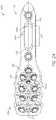
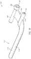
- FIG. 3is a perspective view of a lateral side of an anchor trajectory guide
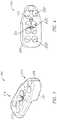
- FIG. 3Ais a perspective view of a lateral side of another example of an anchor trajectory guide
- FIG. 4is a view of a lateral side of the anchor trajectory guide of FIG. 3 ;
- FIG. 5is a view of a superior side of the anchor trajectory guide of FIG. 3 ;
- FIG. 6is a view of an anterior side of the anchor trajectory guide of FIG. 3 ;
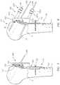
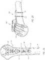
- FIG. 7is an anterior view of a humerus with a fixation plate and an anchor trajectory guide coupled thereto illustrating part of a method of connecting the fixation plate to the humerus;
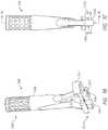
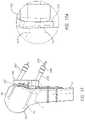
- FIG. 7Ais a perspective view of a slot anchor guide assembly according to one example
- FIG. 7Bis a medial side perspective view of a slot anchor guide of the slot anchor guide assembly of FIG. 7A ;
- FIG. 7Cis a superior or inferior side view of the slot anchor guide of FIG. 7B ;
- FIG. 7Dis a cross-sectional view of the slot anchor guide of FIG. 7B taken through section plane 7 D- 7 D in FIG. 7C ;
- FIG. 7Eis a medial side view of the slot anchor guide of FIG. 7B ;
- FIG. 7Fis a perspective view of a slot anchor guide assembly according to another example.
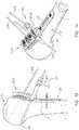
- FIG. 8shows a part of a method of connecting the fixation plate to the humerus following the part of the method illustrated in FIG. 7 in which K-wires are placed through anchor sleeves and K-wire sleeves mated with medial calcar and anterior superior access apertures;
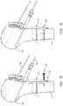
- FIG. 9shows a part of a method of connecting the fixation plate to the humerus following the part of the method illustrated in FIG. 8 in which the fixation plate and the guide are secured in a selected position;
- FIG. 10is a perspective view of one example of a medial calcar guide
- FIGS. 11 and 12are examples of another medial calcar guide
- FIGS. 13 and 14show variations methods of confirming the position of the fixation plate using the medial calcar guide of FIG. 10 ;
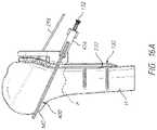
- FIGS. 15, 16, and 16Ashow a part of a method of connecting the fixation plate to the humerus following the part of the method illustrated in FIGS. 13 and 14 , the fixation plate and the guide are secured in a selected position and in which access is provided for an anchor to be advanced to the humerus through the medial calcar guide;
- FIGS. 17 and 17Ashow a part of a method of connecting the fixation plate to the humerus following the parts of the method illustrated in FIGS. 9 and 13 in which an access opening is formed through the lateral cortex of the humerus;
- FIGS. 18-19show a part of a method of connecting the fixation plate to the humerus following the part of the method illustrated in FIGS. 17 and 17A in which an anchor length is determined through the lateral cortex access opening;
- FIG. 20shows an example of a humeral anchor length gauge that can be used to determine an anchor length in the method part illustrated in FIGS. 18-19 ;
- FIG. 21illustrates one example of visual indicia that can be provided at the segment 21 - 21 shown in FIG. 20 to determine an anchor length in the method part illustrated in FIGS. 18-19 ;
- FIG. 22shows a part of a method of connecting the fixation plate to the humerus following the part of the methods illustrated in FIGS. 18-19 in which an anchor of selected length is advanced through the lateral cortex access opening;
- FIG. 23shows a part of a method of connecting the fixation plate to the humerus following the part of the methods illustrated in FIG. 22 in which an anterior-superior lateral cortex access opening is formed;
- FIGS. 24 and 25show lateral and perspective views of an assembly including the fixation plate and a plurality of screw anchors disposed through the fixation plate into the humerus with a medial side of the guide coupled with a lateral side of the fixation plate;
- FIGS. 26 and 27are posterior and medial side views that illustrates a part of a method of connecting the fixation plate to the humerus following the part of the method illustrated in FIGS. 24 and 25 ;
- FIG. 28illustrates a kit comprising a guide, a fixation plate and a plurality of anchors as well as instruments facilitating connection of the fixation plate to the humerus;
- FIG. 29is a perspective view of a tuberosity fracture plate coupled to a greater tuberosity by a plurality of screw anchors;
- FIG. 30Ais a perspective view of a tuberosity fracture plate.
- FIG. 30Bis a view of an anterior side of the tuberosity fracture plate of FIG. 30A ;
- FIG. 30Cis a view of a superior side of the tuberosity fracture plate of FIG. 30A ;
- FIG. 30Dis a cross sectional view of the tuberosity fracture plate of FIG. 30A .
- This applicationis directed to a guide for attaching a fixation plate to a humerus of a patient and to plates that can be so attached.
- the guidecould be used following a fracture.
- the fracturecan be between the metaphysis and the diaphysis of the humerus or along a prominence of a proximal portion of a humerus, such as a tuberosity.
- the guides and methodsare described in connection with the humerus the guides and methods can be used for other bones, such as any long bone fracture or for other orthopedic plate fixation procedures.
- FIG. 1shows anatomy of a glenohumeral joint.
- the jointis formed in part by a head 10 of a humerus H and a glenoid 18 of a scapula 14 .
- the head 10is a convex structure that is generally spherical.
- the glenoid 18includes a concave articular surface upon which the head 10 moves.
- FIG. 1Ashows that the humerus H has a medial side (right side in the view) and a lateral side (left side in the view).
- the medial calcar MCis located at the inferior edge of the head 10 on the medial side of the humerus.
- a lateral cortex LCextends along the lateral side of the bone generally opposite to the medial calcar MC.
- An anterior-superior region AS of the humerus His located on the lateral side and superior to the distal-proximal location of the medial calcar MC.
- the humerushas a proximal portion that is the portion of the humerus adjacent to the glenoid 18 and forming part of the shoulder joint.
- the proximal humerusis sometimes referred to herein as the superior humerus. Proximal and distal in this sense are shown on FIG. 1A with reference to the humerus. In this application a location that is distal to another location refers to being closer to an inferior or elbow-adjacent end of the humerus. A distal portion of the humerus is sometimes referred to herein as an inferior portion of the humerus.
- FIG. 1Ashows a fracture F which is one simple form of fracture that can be treated by the apparatuses and methods discussed below.
- the fracture Fis accompanied by additional fractures around the humeral head 10 . These additional fractures can be treated as well, as discussed further below.
- FIGS. 1B and 1Cshow an example of a tuberosity fracture TF that can be treated as discussed below with a plate that is suitable for repairing the tuberosity fracture TF.
- the tuberosity fracture TFis of a greater tuberosity GT but could be of the lesser tuberosity LT or another prominence of a long bone.
- FIG. 2shows how a fracture F in a humerus H can be treated using a fixation plate assembly 90 .
- the fixation plate assembly 90includes a fixation plate 100 and a plurality of polyaxial anchors 130 in one embodiment.
- the fixation plate 100can have a lateral side 108 configured to face away from the humerus H and a medial side 112 (see FIG. 7 ) configured to face the humerus H.
- the medial side 112can be in direct contact with a lateral surface LS of the humerus H in some applications.
- the fixation plate 100preferably is configured to work well for an entire population of patients.
- the proximal-distal dimensionsenable the fixation plate 100 to span a wide range of neck fractures.
- the anterior-posterior dimensionsallow the fixation plate 100 to be placed on the lateral surface LS of a wide range of bone sizes.
- the fixation plate 100can include a distal portion 116 and a proximal portion 118 .
- the distal portion 116is disposed between the humeral neck and the end of the humerus H forming a portion of the elbow joint.
- the distal portion 116is disposed between the fracture F and the end of the humerus H forming a portion of the elbow joint.
- the proximal portion 118is positioned proximal of the humeral neck or of the fracture F.
- the proximal portion 118can be configured to be secured to the lateral surface LS of the humerus H in the region of the head of the humerus H.
- the proximal portion 118can include an array of anchor apertures 134 .
- the anchor apertures 134can be disposed about the periphery of the proximal portion 118 of the fixation plate 100 .
- One or more or all of the anchor apertures 134can be suited to mate with polyaxial anchors 130 .
- the engagement between the polyaxial anchor 130 and the anchor aperture 134allow the anchor to be directed along a range of directions rather than just being directed along a single axis as is provided with a more simple thread arrangement.
- the fixation plate 100enables a medial end 142 of the polyaxial anchors 130 to span across cancellous bone of the humerus H to engage an opposing cortical bone region CB.
- a lateral end 146 of the polyaxial anchors 130is configured to engage cortical bone at or adjacent to the lateral surface LS of the humerus H.
- the lateral end 146also has a head portion 134 A that is configured to engage a corresponding one of the anchor apertures 134 .
- FIG. 2 and FIG. 27show that when the fixation plate 100 is coupled with a humerus H the polyaxial anchors 130 are generally splayed out.
- two anchorsare splayed when they are disposed in space along longitudinal axes that are not parallel to each other.
- FIGS. 2 and 27show that the anchors 130 are generally splayed out with respect to a medial-lateral and proximal-distal plane PL of the humerus H. That is, a plurality of, e.g., four, polyaxial anchors 130 can be secured through an anterior portion of the fixation plate 100 to the lateral surface LS of the humerus H.
- Another plurality of, e.g., four, polyaxial anchors 130can be secured to a posterior portion of the fixation plate 100 to the lateral surface LS of the humerus H.
- the polyaxial anchors 130can be oriented such that medial ends 142 thereof are more anterior or more posterior than are lateral ends 146 thereof. Described another way, the lateral ends 146 can be located closer to the medial-lateral and proximal-distal plane PL than are the medial ends 142 thereof.
- FIG. 2 and FIG. 27also show that the fixation plate 100 can be configured to engage some anchors along the medial-lateral and proximal-distal plane PL.
- one polyaxial anchor 130can be disposed on the medial-lateral and proximal-distal plane PL in a central portion of the fixation plate 100 .
- one or a plurality of, e.g., two, polyaxial anchors 130can be secured to anchor apertures 134 in the distal portion 116 of the fixation plate 100 and therethrough to a portion of the humerus H distal to the head 10 or distal to the fracture F.
- the fixation plate 100includes a slot 160 in the distal portion 116 that facilitates some of these methods.
- the slot 160can extend along a length of the distal portion 116 .
- the slot 160is aligned with a longitudinal axis of the fixation plate 100 and so can be positioned to symmetrically straddle the medial-lateral and proximal-distal plane PL.
- the slot 160can have a smooth inner surface 161 to engage with a non-locking anchor 132 (see FIG. 2 ).
- the slot 160allows the fixation plate 100 to move in a proximal-distal direction and also to rotate about the non-locking anchor 132 prior to placement of other anchors through the fixation plate 100 .
- the fixation plate 100can have one or a plurality of suture apertures 164 disposed about the periphery thereof.
- the suture apertures 164enable a surgeon to secure fracture portions to the fixation plate 100 .
- fractured portions of the headcan include the greater and/or the lesser tuberosities.
- These bone portionsare usually attachment points for soft tissue, e.g., rotator cuff portions.
- the soft tissuetends to pull these fractured pieces medially.
- the suture apertures 164can be used to pull these fracture pieces back laterally to engagement with the rest of the head 10 of the humerus H such that the humerus can heal properly.
- suture apertures 164 on the proximal end of the fixation plate 100there can be one or two suture apertures 164 on the proximal end of the fixation plate 100 .
- the suture apertures 164 on the anterior side of the fixation plate 100are oriented anteriorly.
- the suture apertures 164 on the posterior side of the fixation plate 100are oriented posteriorly.
- the suture apertures 164can be oriented away from the center of the fixation plate 100 .
- the fixation plate 100can be located on the lateral surface LS and not extend around to the anterior surface or the posterior surface of the humerus H.
- the fixation plate 100includes scallops 168 that are located between the suture apertures 164 . The scallops 168 reduce the anterior and posterior extent of the fixation plate 100 , keeping the plate as low profile in the anterior and posterior directions.
- the fixation plate 100can be configured to mate with an anchor trajectory guide 200 , which is discussed below in FIGS. 3-6 .
- the fixation plate 100can have a locating aperture 120 .
- the locating aperture 120can extend from the lateral side 108 toward the medial side 112 .
- the locating aperture 120can extend from the lateral side 108 to an end portion within the thickness of the fixation plate 100 , e.g., as a blind hole.
- the locating aperture 120can extend entirely through the thickness of the fixation plate 100 from the lateral side 108 to the medial side 112 .
- mate the anchor trajectory guide 200 with the fixation plate 100can include providing a protrusion on the lateral side 108 of the fixation plate 100 that extends laterally toward and into the anchor trajectory guide 200 .
- the lateral side 108has contours that mate in a positive-negative manner with a medial side 208 of the anchor trajectory guide 200 .
- positive-negative mannerrefers to a concavity in one of the lateral and medial sides 108 208 being configured to be received in a convexity formed at a corresponding location of the other of the lateral and medial sides 108 , 208 .
- the fixation plate 100can also include a coupling aperture 172 that can used to further secure the fixation plate 100 to the anchor trajectory guide 200 .
- the coupling aperture 172can also be seen in FIG. 7F .
- the coupling aperture 172can be a through-hole or a blind recess.
- the coupling aperture 172can include threads to engage a screw that is advanced through the anchor trajectory guide 200 as discussed further below.
- the fixation plate 100may be beneficial to form as a patient specific device.
- the medial side 112 of the fixation plate 100 in the proximal portion 118can be formed with a curvature matching the curvature of the head 10 of the humerus H of the specific patient being treated.
- the location of a change in curvature or profile from the proximal portion 118 to the distal portion 116can be selected to match the location of the transition from the long shaft portion of the humerus H to the head 10 thereof.
- the curvature in this direction on the medial side 112 of the fixation plate 100can be configured to match that of the lateral surface LS of the humerus H.
- An anterior-posterior curvature of the medial side 112 in the proximal portion 118can be different from, e.g., larger than, that of the distal portion 116 of the fixation plate 100 .
- a process for forming a patient specific version of the fixation plate 100can include obtaining imaging of (e.g., pre- or intra-operative imaging) a humerus.
- the imagingcan be that of the humerus H that is affected and to be treated.
- portions of the lateral surface LSare not altered by the fracture.
- the fracture illustrated in FIG. 3does not affect the lateral surface LS of the head 10 of the humerus H. So, the curvature thereof can be obtained even from an image of the fractured humerus H. Similarly the curvature of the humerus H distal the fracture F may be unaffected by the fracture.
- the fractureis such that the form of the lateral surface LS of the humerus H in the fracture state does not provide good information about the proper shape of the fixation plate 100 .
- imagingeither pre-operative or intra-operative
- the fixation plate 100can be formed using additive manufacturing techniques, such as 3 D printing, DMLS, and other similar techniques.
- FIG. 2Aillustrates a humeral fixation plate 100 A that is similar to the humeral fixation plate 100 except as described differently above or elsewhere herein.
- the disclosure of the humeral fixation plate 100can supplement the disclosure of the humeral fixation plate 100 A.
- the disclosure of the humeral fixation plate 100 Acan supplement the disclosure of the humeral fixation plate 100
- the humeral fixation plate 100 Aincludes a lateral side 108 and a medial side 112 .
- the lateral side 108is the portion of the humeral fixation plate 100 A that faces away from the humerus H when the humeral fixation plate 100 A is applied thereto.
- the medial side 112is the portion of the humeral fixation plate 100 A that contacts the humerus H when the humeral fixation plate 100 A is applied thereto.
- the humeral fixation plate 100 Ahas a thickness between the lateral side 108 and medial side 112 that can be uniform such that the plate is generally uniformly stiff along a longitudinal axis 159 thereof.
- the humeral fixation plate 100 Acan respond to typical load in surgery by not preferentially bending at any particular location there.
- the humeral fixation plate 100 Acan have a bend zone, e.g., a thinner region as discussed below in connection with the tuberosity fracture plate 600 such that the humeral fixation plate 100 A can be shaped intra-operatively.
- the humeral fixation plate 100 Acan have a distal portion 116 and a proximal portion 118 .
- the proximal portion 118generally can be configured to overlay a proximal portion of the humerus H when applied thereto.
- the distal portion 116can be configured to extend distal of the metaphysis of the humerus H and can overlay a portion of a diaphysis of the humerus H when applied thereto. In some applications the distal portion 116 can be disposed across a fraction of the humerus H, e.g., as shown in FIGS. 1A and 2 .
- the proximal portion 118can be configured to be connected to a head portion of the humerus H.
- the proximal portion 118can be wider in a direction transverse to the longitudinal axis 159 and to the thickness of the humeral fixation plate 100 A than is the distal portion 116 .
- the humeral fixation plate 100 Acan have a slot 160 A that is similar to the slot 160 except as described differently.
- the slot 160 Acan be disposed through the distal portion 116 from the lateral side 108 to the medial side 112 of the humeral fixation plate 100 A.
- the slot 160 Acan extend along the longitudinal axis 159 .
- the slot 160 Acan extend from a first end 162 to a second end 163 along the longitudinal axis 159 .
- the first end 162can be disposed adjacent to the proximal portion 118 .
- the second end 163can be disposed adjacent to the distal end of the humeral fixation plate 100 A.
- the slot 160 Aenables the surgeon to adjust the position of the humeral fixation plate 100 A relative to the humerus H along a proximal-distal (or inferior-superior) direction.
- the slot 160 Acan have a plurality of discrete position sites 167 that assist in the process of placing the humeral fixation plate 100 A.
- the plurality of discrete position sites 167are useful when the humeral fixation plate 100 A is repositioned during the use thereof, as discussed further below.
- the plurality of discrete position sites 167can include a plurality of concavities 167 A.
- the concavities 167 Acan include scallop disposed along the length of the slot 160 A.
- a non-locking anchor 132can be placed in the slot 160 A (see FIGS. 2B-C ).
- the slot 160 Aalso can include a visual spacing indicator 169 disposed along the slot 160 A.
- the visual spacing indicator 169can include one or a plurality of lines 171 .
- the lines 171can be formed transverse to the longitudinal axis 159 .
- the lines 171can extend away from the slot 160 A toward a perimeter of the distal portion 116 .
- each of the lines 171extends from a central portion of one of the concavities 167 A.
- the lines 171can be provided on one side of the slot 160 A or on both sides of the slot 160 A.
- the spacing between the lines 171can be provided to assure that repositioning of the humeral fixation plate 100 A is successful.
- the spacing between the lines 171can assure that a K-wire 296 placed through a positioning channel 296 A of the humeral fixation plate 100 A will not be in a same bone location after repositioning the plate 100 A as when the K-wire 296 was initially placed through the positioning channel 296 A of the plate 100 A.
- the polyaxial anchors 130extend through the humerus H such that the medial ends 142 thereof extend to and are lodged in opposing cortical bone region CB.
- the cortical bone region CB of the head 10 of the humerus His an outer shell of the head. It is desired that the contact surface between the medial side 112 of the fixation plate 100 and the lateral surface LS of the humerus H be bounded by a smaller area than an area bounding all of the medial ends 142 of the polyaxial anchors 130 .
- the polyaxial anchors 130generally are implanted in a splayed orientation to achieve this.
- the bone of the humerus His irregular it is not a simple task to assure that the medial ends 142 of the polyaxial anchors 130 reach the opposing cortical bone region CB through the anchor apertures 134 of the fixation plate 100 while, in some applications, at the same time achieving a high degree of splaying.
- a proper splayed arrangement for a large patientmay result in exposed screw tips on the medial side of the humerus which could even be exposed in the articular surface. This result would be disadvantageous as potentially resulting in scoring of or otherwise damaging the articular surface of the glenoid.
- the anchor trajectory guide 200helps to solve these problems.
- the anchor trajectory guide 200includes a body 204 that has a medial side 208 and lateral side 212 .
- the medial side 208is a first side and the lateral side 212 is a second side.
- the medial side 208is configured to mate with, e.g., to be in direct contact with, the lateral side 108 of the fixation plate 100 as discussed above and further below.
- the lateral side 212is exposed when the anchor trajectory guide 200 is coupled with the fixation plate 100 such that access can be provided to a plurality apertures, including a plurality of guide apertures 232 , a pin aperture 236 , and a fastener aperture 237 (see FIG. 4 ).
- a plurality of, e.g., six, guide apertures 232are provided in a proximal portion 218 of the anchor trajectory guide 200 and a plurality of, e.g., three, guide apertures 232 are provided in a distal portion 216 of the anchor trajectory guide 200 .
- the guide apertures 232can extend from a first opening on the medial side 208 to a second opening on the lateral side 212 .
- the proximal portion 218 of the anchor trajectory guide 200is configured to be disposed over the proximal portion 118 of the fixation plate 100 when the fixation plate 100 and the anchor trajectory guide 200 are coupled together. At least the medial side 112 and in some cases both the medial side 112 and the lateral side 108 of the proximal portion 118 are arcuate in form.
- the fixation plate 100preferably has a concavity on the medial side 112 such that the convexity of the humerus H can be received in or accommodated in the proximal portion 118 of the fixation plate 100 .
- the concavity on the medial side 112may be generic or patient specific.
- the distal portion 116 of the fixation plate 100generally extends along the neck region and distal of the neck region of the humerus H and thus has less or no concavity in the proximal-distal direction.
- the distal portion 116extends from an end of the proximal portion 118 .
- the proximal portion 218is gradually thinner in the medial-lateral direction toward the proximal terminal end of the anchor trajectory guide 200 .
- the proximal portion 218is gradually thicker in the medial-lateral direction toward the distal portion 216 .
- the variation in thicknessis due to the configuration of the anchor trajectory guide 200 to accommodate the arcuate shape of the lateral side 108 of the proximal portion 118 of the fixation plate 100 .
- the thickness of distal portion 216 of the anchor trajectory guide 200 in the medial-lateral directionis less variable.
- the distal portion 216can have a generally constant thickness in the medial-lateral direction between the distal end of proximal portion 218 and the distal terminal end of the anchor trajectory guide 200 .
- the guide apertures 232are arranged to provide anchorage to cortical bone portions dispersed around the head 10 of the humerus H.
- one or more, e.g., two, superior guide apertures 232 Scan be provided to direct creation of probe channel PC and thereby anchor channels toward a superior portion of the head 10 .
- a plurality of, e.g., four, central guide apertures 232 Ccan be provided in a central portion of the proximal portion 218 of the anchor trajectory guide 200 .
- the central guide apertures 232 Ccan be used to form probe channel PC and thereby anchor channels for directing anchors into cortical bone regions in a central portion of the head 10 .
- a plurality of, e.g., three, inferior guide apertures 232 Ican be provided to enable formation of probe channel PC and thereby anchor channels that are directed form the lateral surface LS of the humerus H to the medial calcar MC thereof.
- FIG. 6shows that the pin aperture 236 can extend from the lateral side 212 to the medial side 208 along a longitudinal axis 238 .
- the longitudinal axis 238preferably is non perpendicular to the lateral side 212 but rather is disposed at an acute angle to the lateral side 212 .
- an angle of between 30 and 60 degrees, e.g., about 50 degreescan be provided between a longitudinal axis 213 of the lateral side 212 and the longitudinal axis 238 .
- the anchor trajectory guide 200also includes a locator 220 provided on the medial side 208 that can be used to couple the anchor trajectory guide 200 to the fixation plate 100 .
- the locator 220can be configured as a protrusion with a fixed end disposed at or coupled with the medial side 208 and a free end disposed away from the medial side 208 .
- the free end of the locator 220can be disposed medially of the medial side 208 .
- the free end of the locator 220can be disposed along a longitudinal axis 222 of the locator 220 that extends through the free end of the locator and that intersects the lateral side 212 .
- the longitudinal axis 222 of the locator 220can be disposed perpendicular to the lateral side 212 in one embodiment.
- the longitudinal axis 222 of the locator 220can be disposed non-parallel to the longitudinal axis 238 .
- An angle of between 5 degrees and about 60 degrees, e.g., about 15 degrees, about 25 degrees or about 35 degreescan be provided between the longitudinal axis 222 of the locator 220 and the longitudinal axis 238 of the pin aperture 236 .
- the locator 220 and the fastener aperture 237can work together to secure the anchor trajectory guide 200 to the fixation plate 100 as discussed further below.
- a screw or other fastenercan be advanced through the fastener aperture 237 and into the coupling aperture 172 .
- the coupling aperture 172can be threaded to engage threads of the screw.
- a friction or interference fitcould be used to couple the anchor trajectory guide 200 to the fixation plate 100 via the fastener aperture 237 and the coupling aperture 172 .
- FIG. 3Aillustrates a anchor trajectory guide 200 A that is a modified example or embodiment of the anchor trajectory guide 200 .
- the anchor trajectory guide 200 Acan include any of the features of the anchor trajectory guide 200 and such descriptions will not be repeated here. Also, structurally compatible features of the anchor trajectory guide 200 A can be incorporated into the anchor trajectory guide 200 .
- the anchor trajectory guide 200 Aincludes an perimeter along which a number of concavities are provided.
- the concavitiesinclude suture slots 233 that are disposed along an anterior side and a posterior side of the anchor trajectory guide 200 A. In the image, the anterior side of the anchor trajectory guide 200 A is generally to the left and the posterior side is generally to the right.
- the anchor trajectory guide 200 Acan also include a superior suture slot 233 disposed at a superior location of the anchor trajectory guide 200 A.
- the suture slots 233align with the suture apertures 164 on the fixation plate 100 . This allows the surgeon to perform any soft tissue or bone fragment suture anchoring to the fixation plate 100 without interference from the anchor trajectory guide 200 A.
- the anchor trajectory guide 200 Acan include the guide apertures 232 disposed in inferior, central and superior locations as discussed above in connection with the anchor trajectory guide 200 .
- the guide apertures 232can include an anterior superior guide aperture 232 A and a posterior superior guide aperture 232 B.
- the guide apertures 232can include a plurality of, e.g., two, anterior central guide apertures 232 D, a plurality of, e.g., two, posterior central guide apertures 232 E.
- the guide apertures 232can include an inferior guide aperture 232 H.
- the inferior terminal end of the anchor trajectory guide 200can be configured to receive a portion of another guide.
- the anchor trajectory guide 200 Acan include a guide groove 234 disposed in the inferior terminal end.
- the guide apertures 232 of the anchor trajectory guide 200 Acan include internal threads 235 disposed through the length of the guide apertures 232 .
- the threads 235are configured such that the direction of advancing an anchor 130 therethrough is fixed and the threading axis is suitable for the size of the humerus being repaired.
- the axis of advancing the poly axial anchors 130 through the fixation plate 100can vary. This can be made possible by any suitable structure in the polyaxial apertures 134 of the plate 100 .
- the threads 235can retain their configuration as the anchors 130 are being advanced therethrough.
- the apertures 134can allow the anchors 130 to be advanced in a range of directions therethrough.
- the apertures 134can have a limited number of thread features (e.g., three or less, two or less, or just one arcuate thread) from the medial to the lateral side of the plate 100 .
- Threads through the apertures 134can be soft enough to allow cross-threading when the anchors 130 are advanced to modify an initial trajectory defined by the threads.
- the threads through the apertures 134can comprise helical or annular arc segments that can be threaded in different directions or axes. Threads through the apertures 134 could also be eliminated by providing an inner surface of the apertures 134 that can yield as the anchor 130 is being advanced along a selected trajectory.
- These polyaxial apertures featurescan be imposed on the apertures 134 of the fixation plate 100 by the configuration of the threads 235 of the anchor trajectory guide 200 or the guide 200 A or of other variants disclosed herein.
- the guide apertures 232can have tapered configurations, slots, or other structures for mating with the sleeves, as discussed further below.
- FIGS. 7-26illustrate various fixation plate methods.
- FIG. 7shows that in one technique the fixation plate 100 is initially placed in contact with the lateral surface LS of the humerus H.
- a medial side 112 of the fixation plate 100can be placed on the lateral surface LS of the humerus H.
- the distal portion 116can be aligned with the lateral surface LS distal of the fracture F, which will usually be distal of the neck of the humerus H.
- a non-locking anchor 132can be placed in the slot 160 (see FIG. 2 ) of the fixation plate 100 in the distal portion 116 .
- the non-locking anchor 132can be placed approximately in the center of the slot 160 or can be guided to the center (or another initial position) by a slot anchor guide assembly 239 including a slot anchor guide 240 as shown in one embodiment in FIGS. 7A-7E .
- the slot anchor guide assembly 239also includes a drill sleeve 260 .
- the drill sleeve 260can be configured to control advancement of a drill but also can be used to couple the slot anchor guide 240 to the fixation plate 100 as discussed further below.
- the slot anchor guide 240includes a lateral portion 242 and a medial portion 244 .
- the lateral portion 242is the portion that is farther away from the lateral surface LS of the humerus H when the slot anchor guide assembly 239 is coupled with the humerus.
- the medial portion 244is the portion that is closer to the lateral surface LS of the humerus H when the slot anchor guide assembly 239 is coupled with the humerus.
- the lateral portion 242includes an elongate cylinder 246 that projects between the terminal lateral end of the slot anchor guide 240 and the medial portion 244 .
- the elongate cylinder 246can be configured with a ribbed outer surface along a portion thereof to help the surgeon grasp the slot anchor guide 240 .
- a slot anchor guide 280can be configured with a handle 282 as discussed further below.
- the lateral portion 242also can include a lumen 248 (see FIG. 7D ) disposed therethrough.
- the lumen 248can be accessed at a terminal lateral end of the slot anchor guide 240 .
- the lumen 248can extend through the lateral portion 242 adjacent to the medial portion 244 .
- the medial portion 244can include a medial projection 250 .
- the medial projection 250can be configured to mate with the slot 160 .
- the inferior-superior extent 250 L of the medial projection 250can be slightly smaller than the inferior-superior extent of the slot 160 .
- the slot anchor guide 240is coupled with the fixation plate 100 using a threaded interface of the drill sleeve 260 , as discussed further below. In other embodiments the slot anchor guide 240 can be configured for positioning the fixation plate 100 .
- the medial projection 250can be made to have a small amount of interference fit with the slot 160 so that the fixation plate 100 can be held on the slot anchor guide 240 as the surgeon moves the slot anchor guide 240 around. This can reduce the amount of direct handling of the fixation plate 100 that is needed during the procedure.
- the medial portion 244can also include one or more anterior-posterior projections 252 .
- the anterior-posterior projections 252are configured to nest over the portions of the fixation plate 100 that are disposed anterior and posterior of the slot 160 .
- the drill sleeve 260can be used to engage the slot anchor guide 240 to the fixation plate 100 by a threaded interface
- the anterior-posterior projections 252have a smaller radius of curvature than does the slot 160 in the anterior and posterior directions on the anterior and posterior sides of the slot 160 and/or mating ridges on these surfaces can be provided for the anterior-posterior projection 252 to grip the fixation plate 100 .
- the anterior-posterior projections 252can flex to grip the fixation plate 100 in the area anterior and posterior of the slot 160 .
- the slot anchor guide 240also can include one or more cleats 254 .
- the cleats 254provide for at least a temporary footing or connection to the lateral surface LS of the humerus H.
- the cleats 254can be configured as short spikes that project medially of the medial projection 250 .
- the cleats 254can be configured to project medially of the medial side 112 of the fixation plate 100 when the slot anchor guide assembly 239 is assembled.
- the cleats 254can be pressed into the cortical bone on the lateral surface LS which will hold the fixation plate 100 in place as the surgeon holds the slot anchor guide 240 .
- the lumen 248can be configured to couple with a guide sleeve, such as any of those disclosed herein.
- the lumen 248can have threads 249 disposed adjacent to the terminal lateral end of the lateral portion 242 .
- a guide sleeveis disposed in the lumen 248 and mated with the threads 249 a medial end of the sleeve can be disposed adjacent to the lateral surface LS of the humerus H to provide access for a non-locking anchor 132 advanced through the sleeve.
- the slot anchor guide assembly 239can be coupled together using the drill sleeve 260 .
- the drill sleeve 260can have a lateral portion 262 , a medial portion 264 , and a lumen 268 disposed through the lateral and medial portions 262 , 264 through an elongate cylinder 266 .
- the medial portion 264can include a transverse projection 270 .
- the transverse projection 270can include a short cylindrical shoulder that is configured to mate with a superior-inferior projection 257 .
- the transverse projection 270can have a planar side that contacts a planar lateral side of the superior-inferior projection 257 .
- the anchor trajectory guide 200 and the anchor trajectory guide 200 Acan be configured with a guide groove 234 .
- the guide groove 234can be configured to receive the curved free end of the superior-inferior projection 257 so that the slot anchor guide 240 and the anchor trajectory guides 200 , 200 A can nest together in an assembly.
- the slot anchor guide 240can also be oriented 180 degrees from the orientation in FIG. 7A with the superior-inferior projection 257 aligned with and coupled to the inferior-most anchor aperture 134 .
- a medial end of the drill sleeve 260can be coupled to one of the anchor aperture 134 in the fixation plate 100 by way of threads disposed on an outside surface of the drill sleeve 260 .
- the medial end of the drill sleeve 260can be advanced through an anchor hole 258 in the slot anchor guide 240 until threads thereon mate with threads in the anchor aperture 134 . Thereafter the lateral portion 242 and/or the lateral portion 262 can be used to manipulate any or all of the slot anchor guide assembly 239 .
- FIG. 7Fillustrate a slot anchor guide assembly 279 that is similar to the slot anchor guide assembly 239 except as described differently below.
- the slot anchor guide assembly 279includes a slot anchor guide 280 and the drill sleeve 260 .
- the slot anchor guide 280includes a handle 282 .
- the handle 282has a fixed end 284 that is coupled with and extends from one side of a cylindrical body in a lateral portion of the slot anchor guide 280 .
- the handle 282extends longitudinally between a free end 286 and the fixed end 284 .
- the handle 282is configured to enable the surgeon to move the slot anchor guide 280 and thereby the fixation plate 100 .
- FIG. 7Fshows the slot anchor guide assembly 279 coupled with the fixation plate 100 in an opposite orientation to that of FIG. 7A .
- the superior-inferior projection 257 of the slot anchor guide 280is oriented inferiorly.
- the anchor hole 258 in the superior-inferior projection 257is aligned with the distal or inferior-most anchor aperture 134 in the fixation plate 100 .
- the drill sleeve 260is aligned with and advanced through the superior-anchor hole 258 and into the anchor aperture 134 . Threads on the medial portion 264 of the drill sleeve 260 are advanced into the threads in the anchor aperture 134 until the transverse projection 270 comes into contact with the lateral side of the superior-inferior projection 257 .
- Both the superior and the inferior orientations of the slot anchor guides 240 , 280allow the anchor trajectory guide 200 to be coupled with the fixation plate 100 at the same time as the guides 240 , 280 .
- the orientation of FIG. 2Fadvantageously provides more clearance between the inferior end of the anchor trajectory guide 200 and the slot anchor guides 240 , 280 .
- the anchor trajectory guide 200is coupled with the fixation plate 100 .
- the medial side 208 of the anchor trajectory guide 200can be placed up against the lateral side 108 of the fixation plate 100 .
- the locator 220 anchor trajectory guide 200can be aligned with the corresponding locating aperture 120 of the fixation plate 100 and inserted into the aperture.
- FIG. 7shows that the profile of the medial side 208 is matched to the profile of the lateral side 108 of the fixation plate 100 .
- the fixation plate 100can nest into the concavity of the medial side 208 in the proximal portion 218 of the anchor trajectory guide 200 .
- the locator 220holds the position of the anchor trajectory guide 200 on the fixation plate 100 a more complete coupling of the anchor trajectory guide 200 can be provided.
- a screwcan be advanced through the fastener aperture 237 and into the coupling aperture 172 as discussed above to provide a secure connection that will persist through the procedure.
- the fixation plate 100can be secured by advancing a K-wire 296 through the pin aperture 236 . Because the pin aperture 236 and the locator 220 converge toward the bone and are on diverging axes away from the bone, e.g., the longitudinal axis 222 and the longitudinal axis 238 are converging toward other another toward the bone, the anchor trajectory guide 200 is held in place relative to the fixation plate 100 .
- the fixed position of the anchor trajectory guide 200 relative to the fixation plate 100allows probe channel PC and corresponding anchor channels to be reliably formed in the correct locations. Prior to forming such channels, however, the location of the fixation plate 100 and the size of the anchor trajectory guide 200 can be confirmed.
- FIG. 8shows that once the anchor trajectory guide 200 is secured to the fixation plate 100 and the non-locking anchor 132 is advanced into the bone through the slot 160 .
- the slot 160advantageously allows distal-proximal motion of the fixation plate 100 after the non-locking anchor 132 is placed but before the plate is fully fixed to the humerus H. If either of the slot anchor guides 240 , 280 is used to place the fixation plate 100 initially such guides 240 , 280 can be removed allowing for inferior-superior adjustment of the fixation plate 100 relative to the lateral surface LS of the humerus H.
- the humeral fixation plate 100 Afacilitates a convenient method of confirming the inferior-superior position of the humeral fixation plate 100 A.
- the K-wire 296is advanced through an aperture in a guide 200 , 200 A and further through the positioning channel 296 A at a first position of the non-locking anchor 132 along the slot 160 A.
- the non-locking anchor 132can be advanced until a head portion thereof is in contact with one of the plurality of discrete position sites 167 , e.g., with one of the concavities 167 A.
- the K-wire 296can be removed from the humerus H.
- the position of the humeral fixation plate 100 Acan be evaluated. If the position is not as desired, the non-locking anchor 132 can be retracted sufficiently to out of engagement with the discrete position site 167 in which it was initially positioned.
- the humeral fixation plate 100 Acan be shifted relative to the non-locking anchor 132 to a plurality of discrete position sites 167 proximal or distal of the initial site, e.g., to a concavity 167 A proximal or distal to the initial concavity.
- the non-locking anchor 132can be advanced into the concavity 167 A at the new position.
- the K-wire 296can be advanced through the guide 200 , 200 A into the humerus H through the positioning channel 296 A.
- the spacing between two adjacent concavities of the concavities 167 Acan be enough to assure that the K-wire 296 is not in the same position, e.g., in the channel that was formed in the humerus H in the first insertion.
- the spacing between plurality of discrete position sites 167can be one-half the diameter of the K-wire 296 , e.g., about 1 mm in one embodiment. In other embodiment, the spacing is less or greater.
- the spacingcan be about 2 mm, about 3 mm or about 4 mm in various modified embodiments.
- the visual spacing indicator 169e.g., the lines 171 , can be positioned at each or at alternating concavities 167 A.
- the spacing indicator 169can be at greater intervals, e.g., every third or fourth concavity.
- the K-wireis removed from the humerus H.
- the position of the humeral fixation plate 100 Ais shifted proximally or distally (e.g., inferiorly or superiorly) to a second position of the slot relative to the anchor 132 .
- the second positionis spaced from the first position by an amount greater than the one-half of or the diameter of the K-wire 296 .
- the second positionis provided by advancing the non-locking anchor 132 into a discrete position site of the plurality of discrete position sites 167 spaced along the slot 160 A from the initial site of the plurality of discrete position sites 167 .
- the slot 160 Aenables the non-locking anchor 132 to be retracted out to the concavities 167 A without having to remove the non-locking anchor 132 from the humerus H when shifting among these and other positions that are defined along the slot 160 A.
- the plurality of discrete position sites 167 and the visual spacing indicator 169enhance the usefulness of the humeral fixation plate 100 A by allowing the surgeon to be certain that second and subsequent positions are spaced apart from an initial position. By providing this guidance, the surgeon can more quickly, accurately and confidently proceed through the stages of methods involving the humeral fixation plate 100 A.
- K-wirescan be advanced into the head 10 of the humerus H.
- a first K-wire 296can be advanced toward the medial calcar MC region.
- the appropriate size anchor trajectory guide 200can be confirmed by advancing a second K-wire 296 into a superior anterior guide aperture 232 S.
- the size of the anchor trajectory guide 200can be confirmed. For example, if the proximal end of the anchor trajectory guide 200 is a prescribed distance, e.g., 10 mm, from a proximal aspect of the head 10 then the size of the anchor trajectory guide 200 is appropriate.
- the proximal aspect from which the distance to the anchor trajectory guide 200 is measuredcan be the greater tuberosity GT.
- proximal end of the anchor trajectory guide 200is less than about 10 mm from the proximal aspect of the head 10 then a smaller anchor trajectory guide 200 can be selected. If the proximal end of the anchor trajectory guide 200 is more than about 10 mm from the proximal aspect of the head 10 then a larger anchor trajectory guide 200 can be selected.
- the size of the head 10 of the humerus Hcan be estimated by providing a scale on a K-wire 296 to be inserted into the pin aperture 236 in the center of the anchor trajectory guide 200 after the non-locking anchor 132 has secured the fixation plate 100 to the humerus H.
- the trajectory of the K-wire 296is aligned with the center of the articular surface of the head 10 .
- the scalecan include markings that indicate the length of the K-wire 296 inserted into pin aperture 236 , across the cancellous portion of the head 10 into contact with the cortical bone region CB. From this dimension, the size of the anchor trajectory guide 200 to be used can be determined.
- the K-wire 296can indicate a size (small, medium, large, etc.) of the anchor trajectory guide 200 to be used.
- the K-wire 296can indicate both a dimension and a size in some embodiments.
- FIG. 9shows that securing the fixation plate 100 to the humerus H can be achieved by inserting a polyaxial anchor 130 into an anchor aperture 134 in the distal portion 116 of the fixation plate 100 . The method can then proceed to forming probe channels PC and thereafter to implanting anchors as discussed further below.
- FIGS. 8-18show that guide sleeves can be used in the formation of an inferior probe channel PC.
- a sleeve 300can be mated to the anchor trajectory guide 200 .
- a medial end of the sleeve 300can be inserted into one of the inferior guide apertures 232 I and advanced from the lateral side 212 toward the medial side 208 of the anchor trajectory guide 200 .
- the sleeve 300can be seated in the anchor trajectory guide 200 by engaging threads on the outside surface of the sleeve 300 with internal threads in the inferior guide aperture 232 I.
- the anchor trajectory guide 200can have, as illustrated above in FIG.
- the inner sleeve 320can be inserted by advancing a medial end of the inner sleeve 320 into a lateral end of the sleeve 300 until flanges or hubs 300 a , 320 a at the lateral ends of the sleeve 300 and of the inner sleeve 320 are coupled, e.g., are adjacent to or abutting each other.
- the inner sleeve 320can be seated in or mated to the sleeve 300 by engaging threads on an outside surface of the inner sleeve 320 with internal thread disposed in the inside of the sleeve 300 .
- the inner sleeve 320can be configured to direct a K-wire 296 through the anchor trajectory guide 200 along a guide axis that is pre-defined to an axis in the humerus H to begin the formation of the probe channel PC in a desired location as shown in FIG. 8 .
- the inner sleeve 320can have an inner diameter that is closely matched to an outer diameter of the K-wire 296 such that the trajectory of the K-wire 296 is controlled by the location and orientation of the inferior guide aperture 232 I indirectly, which controls the position and orientation of the sleeves 300 , 320 .
- the K-wire 296can be advanced into the humerus H through the cortical bone at the lateral surface LS and into the cancellous bone within the cortical bone.
- the trajectory of the K-wire 296is pre-defined by the location and orientation of the mating of the fixation plate 100 with the humerus H and by the orientation of the guide apertures 232 as described above. Advancing the K-wire 296 into the humerus H defines the direction along with the probe channel PC will be formed.
- FIG. 8also shows a K-wire 296 can be inserted into a superior portion of the head 10 of the humerus H through the superior guide apertures 232 S. Inserting the K-wire 296 through the superior guide apertures 232 S can include mating sleeve 300 with the superior guide apertures 232 S and inserting the inner sleeve 320 into the sleeve 300 .
- the anchor trajectory guide 200can have, as illustrated above in FIG. 3A in connection with the anchor trajectory guide 200 A, internal threads 235 disposed in an anterior superior guide aperture 232 A and a posterior superior guide aperture 232 B that can be engaged by threads on the exterior surface of the sleeve 300 .
- the position of the fixation plate 100 and the anchor trajectory guide 200are confirmed following insertion of the inferior and superior guide apertures. If the position is confirmed insertion of the K-wires 296 through the superior guide apertures 232 S defines the trajectory of the probe channel PC to be formed later the procedure.
- FIG. 9shows that in some techniques the fixation plate 100 is secured to the humerus H by inserting the polyaxial anchor 130 through the fixation plate 100 as discussed above.
- the distal portion 116can include a polyaxial aperture 134 disposed distally of the slot 160 .
- the polyaxial aperture 104 at this locationis advantageous for providing enhanced security of the fixation plate 100 because it is farthest from the proximal portion 118 through which one or a plurality, e.g., two as illustrated in FIG. 9 , K-wires 296 can be advanced.
- FIGS. 2 and 9shows a configuration in which the non-locking anchor 132 is fully advanced in the slot 160 (See FIG. 2 ) and the polyaxial anchor 130 is fully advanced into the distal polyaxial aperture 134 to immobilize the fixation plate 100 against the lateral surface LS of the humerus H.
- FIGS. 10-16Aillustrate additional approaches to orient the anchor trajectory guide 200 and the fixation plate 100 on the humerus H.
- FIG. 10shows an anatomical alignment guide 400 that can be mated to the anchor trajectory guide 200 .
- the anatomical alignment guide 400can include a sleeve 404 that is configured to mate with one of the guide apertures 232 , e.g., one of the inferior guide apertures 232 I.
- the sleeve 404includes a lumen 408 that extends from a lateral side of the sleeve 404 , e.g., from a flange or hub 406 , to a medial side thereof.
- the lumen 408is configured to slideably receive a K-wire 296 as discussed below.
- the anatomical alignment guide 400also includes a visual alignment member 412 disposed away from the sleeve 404 .
- the visual alignment member 412can include an arcuate member 418 that is coupled at a first end with a lateral end of the sleeve 404 .
- the arcuate member 418can extend in a first portion 418 A away from the sleeve 404 , e.g., in a direction substantially perpendicular to the orientation of the lumen 408 .
- the first portion 418 Acan extend sufficiently from the sleeve 404 to provide clearance between the head 10 of the humerus H and a second portion 418 B of the arcuate member 418 that extends from the first portion 418 B when the anchor trajectory guide 200 is coupled with the fixation plate 100 and thereby with the lateral surface LS of the humerus H.
- the second portion 418 Bcan be substantially parallel to the sleeve 404 in one embodiment.
- the arcuate member 418is configured in the second portion 418 B to extend sufficiently to be positioned or aligned with, e.g., in front of, pre-defined anatomy to which the K-wire 296 disposed through the sleeve 404 is to be aligned.
- the arcuate member 418is configured to extend away from the sleeve 404 to a position in front of (either on the anterior or posterior side of the humerus H) so as to be between the surgeon's eye and the an anatomical landmark.
- the arcuate member 418can provide a visual alignment device for visually aligning the anatomical alignment guide 400 with the landmark.
- the surgeonknows that a K-wire 296 placed through the lumen 408 and through the inferior guide apertures 232 I extends in a direction toward the landmark, e.g., toward the medial calcar.
- FIGS. 13-16Aillustrate this method with the anatomic alignment guide 400 and with an anatomic alignment guide 400 A discussed further below.
- the guide 400 Ais similar to the guide 400 except as described differently below.
- FIGS. 13 and 14are alterative techniques to that shown in FIGS. 7-9 .
- FIG. 13shows the fixation plate 100 mated with the lateral surface LS of the humerus H.
- the anchor trajectory guide 200 Ais mated with the lateral side 108 of the fixation plate 100 .
- the anchor trajectory guide 200could be used, as is illustrated in some of the figures.
- One K-wire 296is placed through the pin aperture 236 into the head 10 of the humerus H.
- the anatomical alignment guide 400 Ais mated with the anchor trajectory guide 200 A.
- the sleeve 404can be inserted into the inferior guide aperture 232 H.
- connection between the sleeve 404 and the inferior guide aperture 232 Hcan be a slip fit, although other connections are possible as well.
- the fixation plate 100can be mated to the humerus H by the non-locking anchor 132 inserted into the slot 160 , which permits the fixation plate 100 to be moved proximally and distally on the humerus H. The movement of the fixation plate 100 can be until the anatomical alignment guide 400 A is aligned with a predefined anatomical landmark, such as the medial calcar MC.
- Aligning the anatomical alignment guide 400 A with the medial calcar MCcan include viewing the anterior surface of the head 10 of the humerus H head on and moving the assembled fixation plate 100 , anchor trajectory guide 200 A, and anatomical alignment guide 400 proximally or distally until the second portion 418 B of the arcuate member 418 is aligned with the medial calcar MC.
- the guide 400 Acan be moved proximally and distally until a K-wire 422 is aligned to the medial calcar MC
- one or both of the K-wires 296can be placed through the anchor trajectory guide 200 or the guide 200 A.
- a superior K-wire 296can be placed through the pin aperture 236 in the anchor trajectory guide 200 or the guide 200 A.
- An inferior K-wire 296can be placed through the inferior guide aperture 232 I to which the anatomical alignment guide 400 or the guide 400 A is mated.
- the K-wire 296can be inserted through the sleeve 404 or through the inner sleeve 320 disposed in the sleeve 404 . As illustrated above in FIG.
- the anchor trajectory guide 200 Ashows that anterior inferior guide aperture 232 F and the posterior inferior guide aperture 232 G have internal threads 235 disposed therein that can be engaged by threads on the exterior surface of the inner sleeve 320 .
- the size of the anchor trajectory guide 200 or the guide 200 Ais confirmed by measuring a distance from a proximal landmark such as the greater tuberosity to the proximal edge of the anchor trajectory guide 200 or the guide 200 A.
- a distance of about 10 mmindicates proper sizing of the anchor trajectory guide 200 or the guide 200 A.
- a smaller distance between the proximal landmark and the proximal edge of the anchor trajectory guide 200 or the guide 200 Asuggests a smaller humerus for which a smaller anchor trajectory guide 200 or guide 200 A is appropriate.
- a larger distance between the proximal landmark and the proximal edge of the anchor trajectory guide 200 or the guide 200 Asuggests a larger humerus for which a larger anchor trajectory guide 200 or guide 200 A is appropriate.
- Other methods of sizing the anchor trajectory guide 200 or guide 200 Acan include placing K-wires 296 in an inferior guide aperture 232 I and in a superior guide aperture 232 S.
- the K-wire 296is properly placed using the anatomical alignment guide 400 or the guide 400 A, e.g., extending to the medial calcar MC the position of the K-wire 296 in the inferior guide aperture 232 I can be confirmed to not be too far proximally suggesting that the anchor trajectory guide 200 or the guide 200 A is too large and not too far distally suggesting that the anchor trajectory guide 200 or the guide 200 A is too small.
- the size of the humerus Hcan also be assessed by the depth into the head 10 that a K-wire 296 inserted into the pin aperture 236 extends.
- Other methods for sizing the anchor trajectory guide 200 or guide 200 Acan include measuring an external dimension of the head 10 of the humerus H or analyzing imaging data (pre-operative or intra-operative).
- FIG. 16shows an alternate method in which after the K-wires 296 have been placed a polyaxial anchor 130 can be advanced through the fixation plate 100 through the guide aperture 232 disposed in the distal portion 216 of the anchor trajectory guide 200 or guide 200 A.
- the combination of the polyaxial anchor 130 and the non-locking anchor 132 in the slot 160secures the fixation plate 100 to the lateral surface LS of the humerus H. This provides a fully secure position for the remaining portions of the procedure.
- a first polyaxial anchor 130can be secured to the head 10 of the humerus H through the anatomical alignment guide 400 as shown in FIG. 16A or through the guide 400 A.
- Placing the polyaxial anchor 130 through the anatomical alignment guide 400 or the guide 400 Acan be directly into the small channel formed by the K-wire 296 or can be following further bone preparation discussed below. If a polyaxial anchor 130 is placed through the anatomical alignment guide 400 or the guide 400 A, following such placement the anatomical alignment guide 400 or guide 400 A can be removed from the anchor trajectory guide 200 or the guide 200 A.
- FIGS. 10 and 16Ashow that one variation of the anatomical alignment guide 400 provides a secondary sleeve 426 in addition to the arcuate member 418 .
- the secondary sleeve 426is disposed between the sleeve 404 and the arcuate member 418 .
- the secondary sleeve 426is disposed anteriorly of the anterior face of the humerus H when the sleeve 404 is mated with the inferior guide aperture 232 I.
- the secondary sleeve 426can receive a K-wire 296 which can slide medially until the K-wire 296 is in front of a relevant landmark, e.g., the medial calcar.
- the secondary sleeve 426can be used when the arcuate member 418 is not in a good position for visualizing the landmark of interest.
- the secondary sleeve 426 and the arcuate member 418extend along planes or longitudinal axes that are not aligned. This enables the arcuate member 418 to be configured to visually align with one anatomical landmark, e.g., the medial calcar MC, and the secondary sleeve 426 to be configured to visually align with a different anatomical landmark.
- FIGS. 11 and 12illustrate the anatomical alignment guide 400 A in more detail.
- the anatomical alignment guide 400 Ais a streamlined form of visual alignment aid.
- the anatomical alignment guide 400 Ahas a sleeve 404 as is described above. Coupled with and disposed to the side of the sleeve 404 is a secondary sleeve 426 .
- the secondary sleeve 426is located at a free end of a transverse projection 428 of the anatomical alignment guide 400 A.
- the transverse projection 428can have a first end couple with the sleeve 404 and a second end disposed away from the sleeve 404 and coupled with the secondary sleeve 426 .
- the secondary sleeve 426can be disposed to the side of (and in use generally anteriorly of) the sleeve 404 and at the end of the free end of the transverse projection 428 .
- FIG. 12shows that the secondary sleeve 426 of the anatomical alignment guide 400 A is disposed entirely to the side of the medial side 208 of the anchor trajectory guide 200 . This allows the secondary sleeve 426 to be medial of the fixation plate 100 and of the lateral surface LS of the humerus H when applied to the patient. This allows the anatomical alignment guide 400 A to be out of the field of view of the head 10 of the humerus H during portions of the method, as illustrated by FIG. 13 .
- the anatomical alignment guide 400 Ais thus lower profile than the anatomical alignment guide 400 so that the anatomical alignment guide 400 A is less obstructive when mated with the lateral surface LS of the humerus H by way of the anchor trajectory guide 200 and the fixation plate 100 .
- the secondary sleeve 426 of the anatomical alignment guide 400 Ais configured to be coupled with a wire 422 .
- the wire 422can be inserted through a lumen in the secondary sleeve 426 .
- the transverse projection 428is long enough that when the sleeve 404 is mated with the inferior guide apertures 232 I the wire 422 can be inserted through the secondary sleeve 426 at a location spaced anterior of an anterior side or posterior of a posterior side of the head 10 of the humerus H.
- the wire 422can be advanced through the secondary sleeve 426 without entering the humerus H but rather being disposed away from and along-side the bone.
- the wire 422can be inserted into the secondary sleeve 426 along-side the head 10 of the humerus H, as shown in FIGS. 13-16 .
- the fixation plate 100 and the anchor trajectory guide 200can be aligned to the bone (e.g., by sliding slot 160 along the non-locking anchor 132 ) until the wire 422 is aligned with a selected anatomical landmark or locations, such as with the medial calcar MC (see FIGS. 13-16 ).
- the transverse projection 428is configured such that the sleeve 404 and the secondary sleeve 426 are aligned and the longitudinal axes of the lumens formed therethrough also are aligned.
- the K-wire 296can be inserted into the sleeve 404 and into the lateral surface LS of the humerus H with confidence that the K-wire 296 will be directed to the medial calcar MC when the wire 422 is directed along the side of the head 10 of the humerus H toward the medial calcar MC.
- the anatomical alignment guide 400 Aalso provides a simple visual confirmation at least on the anterior side thereof.
- a lateral length of the wire 422should cover up and prevent a viewer from seeing a lateral length of the K-wire 296 disposed through the lumen 408 of the sleeve 404 when the alignment of the fixation plate 100 and anchor trajectory guide 200 A or 200 is proper, as seen in comparing FIGS. 13 and 14 .
- a viewer seeing the wire 422 head-onshould only see one wire and should not see the K-wire 296 disposed immediately posterior or behind the wire 422 .
- the anatomical alignment guides 400 , 400 Aprovide convenient way to confirm the fixation plate 100 is properly aligned to the lateral surface LS of the humerus H can be fully secured by inserting the polyaxial anchor 130 into the distal guide aperture 232 .
- FIGS. 17 and 17Ashow a portion of a method that can follow any of the alignment techniques discussed above to form the probe channels PC through the properly sized anchor trajectory guide 200 or guide 200 A.
- the inner sleeve 320 disposed in the inferior guide aperture 232 Ican be exchanged for an inner sleeve 340 that is configured to receive a drill bit 344 .
- the drill bit 344can be configured with the same diameter as the K-wire 296 so this exchange is not necessary in all cases. In many circumstances, the drill bit 344 has a larger diameter than the diameter of the K-wire 296 .
- the drill bit 344can be directly inserted into the sleeve 300 such that the inner sleeve 320 configured for the K-wire 296 can simply be removed and the drill bit 344 can be advanced directly through the sleeve 300 .
- the inner sleeve 340 configured for the drill bit 344is needed, the inner sleeve 340 can be advanced such that the medial end thereof is advanced into an aperture at the lateral end of the sleeve 300 .
- the inner sleeve 340can be docked with the sleeve 300 in any suitable manner, e.g., using a threaded connection, slip fit or friction fit.
- the drill bit 344can be advanced into the humerus H through the lateral surface LS thereof as shown in FIG. 17A .
- the drill bit 344can have a smooth and tapered tip that can be configured to initially enter the lateral surface LS enlarging the hole therethrough formed by the K-wire 296 .
- a length of the drill bit 344 between the tapered tip and the opposite end of the drill bit 344can be threaded to enlarge the small passage formed by the K-wire 296 between the lateral surface LS and the cortical bone region CB opposite the lateral surface LS on the medial side of the head 10 in some techniques.
- the drill bit 344is used to enlarge the opening through the lateral surface LS of the humerus H but not to enlarge the passage formed by the K-wire 296 all the way to the cortical bone region CB.
- FIGS. 18 and 19show that after the drill bit 344 is removed the inner sleeve 340 can be exchanged for a probe 360 .
- the probe 360can be configured to perform multiple functions.
- the probe 360can provides a basis for choosing an appropriate polyaxial anchor 130 from a plurality of anchors, e.g., for choosing the polyaxial anchor 130 that has a length that will result in a medial portion of the polyaxial anchor 130 being embedded in the cortical bone region CB and a lateral portion of the polyaxial anchor 130 engaging one of the locating apertures 120 of the fixation plate 100 .
- FIG. 18shows that the probe 360 can be inserted into the lateral end of the sleeve 300 and the probe 360 can dock with the sleeve 300 .
- the probe 360When the probe 360 is docked with the sleeve 300 , an inner member of the probe 360 can be inserted all the way across the head 10 to the cortical bone region CB. At that point, the indicia 362 at the lateral end of the probe 360 indicate which of the polyaxial anchor 130 is suitable for the particular locating aperture 120 .
- FIG. 19shows that a blunt tip 361 can be provided that is well suited for pushing through the cancellous bone matter within the head 10 of the humerus H to formed the probe channel PC.
- the blunt tip 361preferably is rounded to displace but not attach to tissue that is engaged thereby.
- FIGS. 20-21show one embodiment of the probe 360 in more detail.
- the probe 360includes an outer member 364 and an inner member 365 .
- the outer member 364includes a medial portion 366 and a lateral portion 368 .
- the medial portion 366includes a slender cylindrical portion with a lumen formed therein.
- the lateral portion 368includes an outer surface that can have ribs for gripping by the surgeon and an inner lumen formed therein.
- a shoulder 370can be formed between the medial portion 366 and the lateral portion 368 .
- the shoulder 370can be used in docking the probe 360 to the sleeve 300 .
- the probe 360can be inserted into the sleeve 300 until the shoulder 370 abuts a lateral surface of the probe 360 .
- the lateral portion 368can have an aperture 372 at a lateral end thereof.
- the inner member 365can have a cylindrical medial portion 374 and a graduated lateral portion 376 .
- the cylindrical medial portion 374can be configured to slide within the lumen of the medial portion 366 .
- the cylindrical medial portion 374can be rigid to push cancellous matter aside to form the probe channel PC in some embodiments and can be configured with the blunt (e.g. rounded) tip 361 that can be atraumatic (e.g., configured not to hook or otherwise attach to bone matter).
- the tip 361is configured to be inserted into the bone to enlarge the channel formed by the K-wire 296 to form the probe channel PC. When the tip 361 contacts the cortical bone region CB opposite the lateral surface LS the probe channel PC has been formed.
- the graduated lateral portion 376can be configured to move into or out of the lateral portion 368 of the probe 360 .
- the graduated lateral portion 376can include the indicia 362 formed along a side surface thereof.
- the indicia 362can include numbers indicating the length of the medial portion 374 spanning the cancellous bone to the cortical bone region CB. The same length can inform the choice of a polyaxial anchor 130 to be used in the particular probe channel PC.
- the indicia 362can include any other marking that conveys to the surgeon which of a plurality of different length polyaxial anchor 130 to select (e.g., small, medium, and large).
- FIG. 22shows that in a technique after the size of the polyaxial anchor 130 to be used is selected, the appropriately sized polyaxial anchor 130 can be inserted into the sleeve 300 and advanced into the probe channel PC through one of the inferior guide apertures 232 I. After the polyaxial anchor 130 is fully inserted the medial tip of the polyaxial anchor 130 is lodged in the opposing cortical bone region CB and the lateral end is engaged with one of the distal locating apertures 120 of the fixation plate 100 , as shown in FIG. 23 .
- Using the probe 360ensures that the medial end of the polyaxial anchor 130 when fully advanced does not breach the cortical bone on the medial side of the humerus H, e.g., is not exposed on the articular surface of the humerus H. This is important because it prevents the polyaxial anchor 130 from contacting the articular surface at or on the glenoid of the scapula as discussed above.
- FIG. 23also shows that a technique can continue with using the drill bit 344 to facilitate enlarging an opening through the lateral surface LS of the humerus H formed by a K-wire 296 to enable the probe 360 to be used to aid in selection of an appropriately sized polyaxial anchor 130 and/or to form a probe channel PC through the head 10 of the humerus H.
- the drill bit 344is advanced through the superior guide apertures 232 S guided by the sleeve 300 and the inner sleeve 320 .
- FIGS. 24 and 25show that the processes of forming and probing the probe channels PC and selecting appropriate sized polyaxial anchors 130 and thereafter inserting the polyaxial anchor 130 into the humerus H can be continued until a sufficient number of polyaxial anchor 130 are implanted, e.g., more than half of the anchor aperture 134 and some cases all of the anchor aperture 134 have a polyaxial anchor 130 secured therein. Thereafter the anchor trajectory guide 200 can be undocked form the lateral side 108 of the fixation plate 100 .
- a screwis removed from coupling aperture 172 and the fastener aperture 237 and the locator 220 can be removed from the locating aperture 120 to permit the anchor trajectory guide 200 to be removed from the fixation plate 100 .
- FIG. 26shows that in some techniques at least one of the polyaxial anchors 130 can be implanted after the anchor trajectory guide 200 is removed.
- a polyaxial anchor 130can be implanted on the distal side of the neck of the humerus H, e.g., distal of the fracture F without any guidance from the anchor trajectory guide 200 .
- FIG. 27shows that in some techniques a great deal of splaying is provided among the polyaxial anchor 130 .
- the polyaxial anchor(s) 130 on an anterior side of the medial-lateral and proximal-distal plane PLcan be oriented to diverge from the medial-lateral and proximal-distal plane PL at their medial tips.
- Some, more or all of the polyaxial anchor 130 on a posterior side of the medial-lateral and proximal-distal plane PLcan be oriented to diverge from the medial-lateral and proximal-distal plane PL at their medial tips.
- Providing at least some splayingcreates excellent security and force spreading to assure strong connection of the fixation plate 100 to bone portions located proximal and distal of the fracture F. Greater splaying also assures that the medial end 142 of the non-locking anchor 132 will be outside of or around the periphery of the articular surface of the head 10 . This peripheral positioning of the medial end 142 provides an enhanced degree of safety for the patient.
- the anchor trajectory guide 200can be provided in a range of sizes.
- the anchor trajectory guide 200can have a small size, a medium size, and a large size.
- the large size anchor trajectory guide 200can provide a greater amount of splaying than illustrated in FIG. 27 such that the polyaxial anchor tips are secured in the cortical bone.
- the medial ends 142can be disposed outside of a boundary 500 that is more anterior on one of the medial-lateral and proximal-distal plane PL and more posterior on the opposite side of the medial-lateral and proximal-distal plane PL than is the illustrated by the medial ends 142 shown in FIG. 27 .
- the smaller size anchor trajectory guide 200can provide a lesser amount of splaying than illustrated in FIG. 27 .
- the medial ends 142will be disposed inside a boundary 504 that is less anterior on one of the medial-lateral and proximal-distal plane PL and less posterior on the opposite side of the medial-lateral and proximal-distal plane PL than is the illustrated by the medial ends 142 shown in FIG. 27 .
- the bonewill also be smaller for patient for which the boundary 504 is appropriate. As such the location of the medial ends 142 will generally stay peripheral of the articular surface of the humerus H regardless of the size of the anchor trajectory guide 200 .
- the polyaxial anchor 130enable the same fixation plate 100 to be used with a range of sizes, including enabling the medial end 142 to reach the position shown or either one of the boundaries 500 , 504 . This advantageously simplifies the number of kits and the inventory needed to provide great outcomes for a wide range, if not the entire population, of patients.
- the anchor trajectory guide 200can be patient specific to provide the maximal amount of splaying possible in the bone of the specific patient or to target maximal amount of splaying into good bone and minimize splaying into weakened bone. In that case, the amount of splaying is specific to the patient and can be different for each anchor aperture 134 and for each polyaxial anchor 130 .
- FIG. 28shows an example of a kit 550 that can be provided in some embodiments.
- the kit 550includes a plurality of anchor trajectory guides 200 .
- Each of the anchor trajectory guide 200can include a different size.
- one of the anchor trajectory guide 200can be suitable for an average size humerus
- one of the anchor trajectory guide 200can be suitable for larger humerus sizes
- the periphery of the anchor trajectory guide 200are generally not different, but the locations, positions, orientations, and/or trajectories of the guide apertures 232 through the anchor trajectory guide 200 will be different to assure the medial end 142 are splayed to an appropriate degree.
- the kit 550can also include the fixation plate 100 .
- the kit 550also can include the humeral fixation plate 100 A.
- the kit 550also can include a tuberosity fracture plate 600 discussed further below.
- the kit 550can include a plurality of polyaxial anchor 130 .
- the polyaxial anchor 130will be provided in a range of sizes to facilitate the above methods which provide the distal (medial) tips of the anchors to be lodged in opposing cortical bone but not breaching the opposite (medial) side of the humerus while the proximal (lateral) ends of the polyaxial anchor 130 are engaged with the lateral side 108 of the fixation plate 100 .
- the kit 550can also include one or a plurality of non-locking anchor 132 configured for engaging the slot 160 of the fixation plate 100 .
- the kit 550can also include a plurality of surgical tools, including K-wires 296 , outer sleeves 300 , inner K-wire sleeves 320 , inner probe and screw sleeves 340 , and probe 360 .
- the kit 550can comprise a kit of implantable components and a kit of surgical components.
- FIGS. 1B, 1C, and 29-30Dillustrate a tuberosity fracture plate 600 and the use thereof to repair a tuberosity fracture TF in the humerus.
- the tuberosity fracture plate 600includes a tuberosity end 604 and a distal portion 608 .
- a distance between the tuberosity end 604 and the opposite end of the distal portion 608can be between about 40 mm and about 70 mm, e.g., between 45 mm and 65 mm.
- the distance between the tuberosity end 604 and the opposite end of the distal portion 608can be between 50 mm and 60 mm, e g., about 53 mm.
- the tuberosity end 604includes a first portion 612 and a second portion 616 .
- the first portion 612can be a portion that will overlay a first tuberosity, e.g., a greater tuberosity GT.
- the first portion 612can be used to secure one side of a fractured first tuberosity GT to the rest of the humerus H.
- the second portion 616can be used to secure the other side of a fractured first tuberosity GT to the rest of the humerus H.
- the first portion 612can be used to secure one side of a second tuberosity, e.g., a lesser tuberosity LT to the rest of the humerus H.
- the second portion 616can be used to secure the other side of a fractured second tuberosity LT to the rest of the humerus H.
- a distance between a portion of the first portion 612 disposed opposite the longitudinal axis 648 and a portion of the second portion 616 disposed opposite the longitudinal axis 648can be between about 15 mm and about 45 mm, e.g., between about 20 mm and about 40 mm.
- a distance between a portion of the first portion 612 disposed opposite the longitudinal axis 648 and a portion of the second portion 616 disposed opposite the longitudinal axis 648can be between about 25 mm and about 35 mm, e.g., about 29 mm.
- the first portion 612 and the second portion 616can both be used to secure a greater tuberosity, e.g., the first portion 612 can be used on a left humerus H to secure the greater tuberosity GT and the second portion 616 can be used on a right humerus H to secure the greater tuberosity GT of the right arm.
- the tuberosity fracture plate 600can have a plurality of screw holes.
- a first screw hole 624can be provided on the tuberosity end 604 .
- the first screw hole 624can be disposed in the first portion 612 to hold a polyaxial screw 130 to secure a first tuberosity GT.
- a second screw hole 628can be provided on the tuberosity fracture plate 600 .
- the second screw hole 628can be provided on the distal portion 608 .
- the second screw hole 628also can engage a polyaxial screw 130 to secure the tuberosity fracture plate 600 to the humerus H, e.g., to a portion of the humerus H not on fractured fragment, e.g., the fragment including the first tuberosity GT.
- the tuberosity fracture plate 600can include additional screw holes, e.g., a screw hole 640 can be provided in the distal portion 608 .
- a plurality of screw holes 640can be provided in the distal portion 608 .
- a screw hole 644can be provided in the tuberosity end 604 .
- a plurality of screw holes 644can be provided in the tuberosity end 604 .
- the screw hole or holes 644can be disposed away from the first screw hole 624 .
- the screw hole 644can secure a portion of the humeral head when the first screw hole 624 is secured to the fractured and fragmented first tuberosity GT. Usually all of the screw holes 624 , 644 , will be engaged with a screw 130 .
- FIG. 30Ashows that the plate 600 can have a relief 625 formed in the screw holes 624 , 644 that are off-set from the longitudinal axis 648 .
- the relief 625is formed to allow the screw 130 be inserted into the plate 600 along a trajectory that is perpendicular to a plane tangent to the lateral side of the plate 600 at the longitudinal axis 648 .
- the relief 625can enable a screw 139 to be disposed along a trajectory that is parallel to the trajectory of one or more screws 130 disposed through the screw holes that are on the longitudinal axis 648 , e.g., extending perpendicular to the axis 648 through the holes 640 .
- the first screw hole 624is used to secure the fragmented portion of the humerus H, e.g., the first tuberosity GT and the screw hole or holes 644 is left without any screws in it to minimize the invasiveness of the procedure in the humerus H.
- the tuberosity fracture plate 600can include a bend zone 632 disposed along the length there.
- the bend zone 632can be a portion that is configured to preferentially bend. For example, when a load is applied to the ends of the tuberosity fracture plate 600 the plate bend in the bend zone 632 .
- a bend zone 632is provided between the tuberosity end 604 and the distal portion 608 .
- a plurality of bend zones 632are provided along the length of the tuberosity fracture plate 600 .
- a bend zone 632can be provided between each pair of a plurality of adjacent screw holes 640 .
- the bend zone 632enable a plate that initially disposed along a straight longitudinal axis 648 to be shaped to match the shape of the lateral side of the humerus H.
- the shaped form of the tuberosity fracture plate 600can be adjusted from straight along the longitudinal axis 648 to one or a plurality of curves along the length from the proximal to the distal end of the tuberosity fracture plate 600 .
- the bend zone 632can be formed in any suitable way.
- the tuberosity fracture plate 600can have a portion with a first thickness 654 at one or all of the screw hole 640 and a second thickness 656 in the bend zone 632 .
- the second thickness 656can be less than the first thickness 654 .
- the second thickness 656can be less than 50% of the thickness of the tuberosity fracture plate 600 outside the bend zone 632 .
- the thickness 656can be between 0.5 mm and 1.5 mm, e g., about 1 mm in various embodiments.
- the thickness 656can be between 0.5 mm and 1.5 mm, e.g., about 1 mm Without the bend zone 632 the location of the screw hole 640 would be the location most likely to localize bending.
- the location of the screw hole 640would correspond to a bending location.
- the bend zone 632has a second thickness 656 that is less than the first thickness 654 the bending of the tuberosity fracture plate 600 is focused at the bend zone 632 .
- the second thickness 656can be one-half or less than the first thickness 654 .
- the second thickness 656can be about one-half the first thickness 654 .
- the second thickness 656can be about one-third the first thickness 654 .
- the second thickness 656can be about one-quarter the first thickness 654 .
- FIG. 30Cshows that the tuberosity fracture plate 600 can be pre-formed with transverse curvature.
- the tuberosity fracture plate 600can be curved in the tuberosity end 604 transverse to the longitudinal axis 648 .
- the tuberosity fracture plate 600can be curved in the distal portion 608 transverse to the longitudinal axis 648 .
- FIG. 30Dshows that one or more of the first screw hole 624 , the second screw hole 628 , the screw holes 640 , and the screw hole 644 can be threaded.
- the threaded holes 624 , 628 , 640 , 644can be configured to receive polyaxial screw 130 .
- the threaded holes 624 , 628 , 640 , 644can thus enable the polyaxial screw 130 to be targeted to safe anatomy of the humerus H, e.g., away from the articular surface thereof.
- FIG. 29illustrates the method of securing a fracture of a first, e.g., a greater tuberosity GT.
- the first tuberosity GTis brought into place on the remainder of the humerus H.
- the tuberosity fracture plate 600is placed over the humerus H and the first tuberosity GT.
- a polyaxial screw 130is advanced through the first screw hole 624 and into the first tuberosity GT.
- One or more, e.g., all of the screw hole 640receive a polyaxial screw 130 .
- the tuberosity fracture plate 600Prior to placing some or all of the polyaxial screw 130 the tuberosity fracture plate 600 can be shaped to match the shape of the humerus H.
- the tuberosity fracture plate 600can be bent along one or more of the bend zones 632 to create curvature along the longitudinal axis 648 that matches that of the particular patient's humerus H.
- the tuberosity fracture plate 600can be fully secured to the one once shaped. In some methods, gross shaping is performed by the surgeon. The very act of advancing the polyaxial screw 130 into the tuberosity fracture plate 600 can cause additional bending to further match the tuberosity fracture plate 600 to the shape of the humerus H of the patient.
- the tuberosity fracture plate 600can have one or a plurality of suture apertures 652 .
- the plurality of suture apertures 652can receive a suture to secure one or more bone fragment to the tuberosity fracture plate 600 .
- the first tuberosity GTis too fragmented to allow the polyaxial screw 130 to secure the first tuberosity GT to the tuberosity fracture plate 600 .
- one or more suturescan secure the fragment(s) of the first tuberosity GT to the tuberosity fracture plate 600 and/or to the rest of the humerus H.
- proximalrefers to the direction of the end of the humerus adjacent to the scapula and forming part of the shoulder joint, which may be referred to herein as the superior direction, end or portion
- distalrefers to the direction away from proximal, which can be the end of the humerus forming part of the elbow joint and which may be referred to herein as the inferior direction, end or portion of the humerus.
- a phrase referring to “at least one of” a list of itemsrefers to any combination of those items, including single members.
- “at least one of: A, B, or C”is intended to cover: A, B, C, A and B, A and C, B and C, and A, B, and C.
- Conjunctive languagesuch as the phrase “at least one of X, Y and Z,” unless specifically stated otherwise, is otherwise understood with the context as used in general to convey that an item, term, etc. may be at least one of X, Y or Z. Thus, such conjunctive language is not generally intended to imply that certain embodiments require at least one of X, at least one of Y and at least one of Z to each be present.
- any methods disclosed hereinneed not be performed in the order recited.
- the methods disclosed hereininclude certain actions taken by a practitioner; however, they can also include any third-party instruction of those actions, either expressly or by implication.
- actions such as “inserting a humeral stem into a humerus”include “instructing insertion of a humeral head into a humerus.”
Landscapes
- Health & Medical Sciences (AREA)
- Orthopedic Medicine & Surgery (AREA)
- Surgery (AREA)
- Life Sciences & Earth Sciences (AREA)
- Biomedical Technology (AREA)
- Public Health (AREA)
- Veterinary Medicine (AREA)
- Engineering & Computer Science (AREA)
- Nuclear Medicine, Radiotherapy & Molecular Imaging (AREA)
- Heart & Thoracic Surgery (AREA)
- Medical Informatics (AREA)
- Molecular Biology (AREA)
- Animal Behavior & Ethology (AREA)
- General Health & Medical Sciences (AREA)
- Neurology (AREA)
- Dentistry (AREA)
- Oral & Maxillofacial Surgery (AREA)
- Surgical Instruments (AREA)
- Prostheses (AREA)
Abstract
Description
Claims (20)
Priority Applications (1)
| Application Number | Priority Date | Filing Date | Title |
|---|---|---|---|
| US16/649,956US11426220B2 (en) | 2017-10-11 | 2018-10-10 | Humeral fixation plate guides |
Applications Claiming Priority (3)
| Application Number | Priority Date | Filing Date | Title |
|---|---|---|---|
| US201762571046P | 2017-10-11 | 2017-10-11 | |
| US16/649,956US11426220B2 (en) | 2017-10-11 | 2018-10-10 | Humeral fixation plate guides |
| PCT/US2018/055290WO2019075119A1 (en) | 2017-10-11 | 2018-10-10 | Humeral fixation plate guides |
Related Parent Applications (1)
| Application Number | Title | Priority Date | Filing Date |
|---|---|---|---|
| PCT/US2018/055290A-371-Of-InternationalWO2019075119A1 (en) | 2017-10-11 | 2018-10-10 | Humeral fixation plate guides |
Related Child Applications (1)
| Application Number | Title | Priority Date | Filing Date |
|---|---|---|---|
| US17/869,011ContinuationUS12137953B2 (en) | 2017-10-11 | 2022-07-20 | Humeral fixation plates |
Publications (2)
| Publication Number | Publication Date |
|---|---|
| US20200237418A1 US20200237418A1 (en) | 2020-07-30 |
| US11426220B2true US11426220B2 (en) | 2022-08-30 |
Family
ID=64316972
Family Applications (3)
| Application Number | Title | Priority Date | Filing Date |
|---|---|---|---|
| US16/649,956ActiveUS11426220B2 (en) | 2017-10-11 | 2018-10-10 | Humeral fixation plate guides |
| US17/869,011ActiveUS12137953B2 (en) | 2017-10-11 | 2022-07-20 | Humeral fixation plates |
| US18/926,682PendingUS20250049484A1 (en) | 2017-10-11 | 2024-10-25 | Humeral fixation plates |
Family Applications After (2)
| Application Number | Title | Priority Date | Filing Date |
|---|---|---|---|
| US17/869,011ActiveUS12137953B2 (en) | 2017-10-11 | 2022-07-20 | Humeral fixation plates |
| US18/926,682PendingUS20250049484A1 (en) | 2017-10-11 | 2024-10-25 | Humeral fixation plates |
Country Status (5)
| Country | Link |
|---|---|
| US (3) | US11426220B2 (en) |
| EP (1) | EP3694430A1 (en) |
| CA (1) | CA3078249A1 (en) |
| MX (1) | MX2020003481A (en) |
| WO (1) | WO2019075119A1 (en) |
Families Citing this family (5)
| Publication number | Priority date | Publication date | Assignee | Title |
|---|---|---|---|---|
| TWI836034B (en)* | 2019-03-13 | 2024-03-21 | 新加坡國立大學 | Orthopaedic implant, orthopaedic trauma plate, and method for forming same |
| US10743922B1 (en) | 2019-09-27 | 2020-08-18 | Trilliant Surgical Llc | Variable angle locking construct for orthopedic applications |
| USD949341S1 (en) | 2020-09-29 | 2022-04-19 | Trilliant Surgical Llc | Bone fixation plate |
| CN115444538B (en)* | 2022-09-13 | 2024-12-24 | 上海焰医数字医疗科技有限公司 | Proximal humeral fracture plate implantation guide |
| EP4454582A1 (en)* | 2023-04-27 | 2024-10-30 | Stryker European Operations Limited | Bone plate for securing a fractured bone |
Citations (358)
| Publication number | Priority date | Publication date | Assignee | Title |
|---|---|---|---|---|
| US2500370A (en) | 1947-06-30 | 1950-03-14 | Mckibbin Genevieve | Repair of femur fracture |
| US2682265A (en) | 1951-12-28 | 1954-06-29 | Marie B Collison | Trochanteric plate and artificial femoral head |
| US3334624A (en) | 1963-09-26 | 1967-08-08 | Synthes Ag | Intramedullary nail |
| US3433220A (en) | 1966-12-30 | 1969-03-18 | Robert E Zickel | Intramedullary rod and cross-nail assembly for treating femur fractures |
| US3709218A (en) | 1970-04-24 | 1973-01-09 | W Halloran | Combination intramedullary fixation and external bone compression apparatus |
| US3781917A (en) | 1970-10-13 | 1974-01-01 | R Mathys | Hip joint prosthesis |
| US3842825A (en) | 1973-11-12 | 1974-10-22 | R Wagner | Hip fixation device |
| DE7115713U (en) | 1971-02-26 | 1975-06-26 | Fischer A | |
| US3939498A (en) | 1974-05-29 | 1976-02-24 | National Research Development Corporation | Endoprosthetic femoral head |
| GB1428653A (en) | 1972-02-23 | 1976-03-17 | Nat Res Dev | Fracture fixing device |
| US3973278A (en) | 1974-07-08 | 1976-08-10 | Yakov Isaevich Shersher | Artificial hip-joint |
| US3977398A (en) | 1976-01-12 | 1976-08-31 | The Sampson Corporation | Fluted sub-trochanteric nail system |
| US4011863A (en) | 1976-07-19 | 1977-03-15 | Zickel Robert E | Supracondylar prosthetic nail |
| US4055172A (en) | 1973-07-18 | 1977-10-25 | Josef Ender | Nail and set for correctly resetting fractured bones for their immediate re-use |
| US4091806A (en) | 1976-01-13 | 1978-05-30 | Jacob Aginsky | Intramedullary compression nail for the treatment of bone fractures |
| US4101985A (en) | 1976-03-20 | 1978-07-25 | Friedrich Baumann | Hip-joint prosthesis |
| US4103683A (en) | 1977-06-03 | 1978-08-01 | Neufeld John A | Sub-trochanteric nail |
| US4135507A (en) | 1977-05-20 | 1979-01-23 | Harris Leslie J | Condylocephalic nail for fixation of pertrochanteric fractures |
| US4169470A (en) | 1977-10-19 | 1979-10-02 | Ender Hans G | Surgical nail for use in setting bone fractures, and tool for emplacing same |
| US4227518A (en) | 1978-02-12 | 1980-10-14 | Jacob Aginsky | Intramedullary retraction nail for fixation of comminuted fractured bones |
| US4237875A (en) | 1979-02-23 | 1980-12-09 | Towmotor Corporation | Dynamic intramedullary compression nailing |
| US4274754A (en) | 1979-10-31 | 1981-06-23 | Grumman Aerospace Corporation | Double locking device |
| US4338926A (en) | 1980-11-21 | 1982-07-13 | Howmedica, Inc. | Bone fracture prosthesis with controlled stiffness |
| US4393868A (en) | 1981-02-20 | 1983-07-19 | Ace Orthopedic Manufacturing Inc. | Colles fracture fixature device |
| EP0091499A1 (en) | 1982-04-10 | 1983-10-19 | Metallwerk Plansee Gesellschaft M.B.H. | Fluted intramedullary leg nail |
| US4423721A (en) | 1978-09-04 | 1984-01-03 | Schwarzkopf Development Corporation | Device for insertion and extraction of medullary nails |
| US4446857A (en) | 1978-09-04 | 1984-05-08 | Schwarzkopf Development Corporation | Medullary nail and process for the production thereof |
| US4453539A (en) | 1982-03-01 | 1984-06-12 | The University Of Toledo | Expandable intramedullary nail for the fixation of bone fractures |
| US4467793A (en) | 1979-12-14 | 1984-08-28 | Ender Hans G | Instrumentarium for reducing and fixing of pertrochanterous and subtrochanterous fractures as well as insert member forming part of this instrumentarium |
| EP0118778A1 (en) | 1983-03-09 | 1984-09-19 | HOWMEDICA INTERNATIONAL, INC. Zweigniederlassung Kiel | Fixing nail |
| US4473069A (en) | 1981-07-17 | 1984-09-25 | Lars Kolmert | Device for interconnecting an elastic nail and a cross screw |
| US4475545A (en) | 1982-12-06 | 1984-10-09 | Ender Hans G | Bone-nail |
| US4483335A (en) | 1982-06-02 | 1984-11-20 | Tornier S.A. | Nails for femoral fractures |
| US4493317A (en) | 1980-11-20 | 1985-01-15 | Synthes Ltd. (U.S.A.) | Surgical compression plate and drill guide |
| US4513744A (en) | 1981-03-16 | 1985-04-30 | Synthes Ag | Surgical compression plate |
| US4522202A (en) | 1981-01-12 | 1985-06-11 | Schwarzkopf Development Corporation | Curved intramedullary lower leg spike |
| US4541424A (en) | 1982-03-30 | 1985-09-17 | Howmedica International, Inc. | Distal aiming device for a locking nail |
| DE8533134U1 (en) | 1984-11-30 | 1986-04-03 | Institut Straumann Ag, Waldenburg | Device for treating a bone |
| US4590930A (en) | 1983-06-22 | 1986-05-27 | Lloyd A. Kurth | Fixation device and process for an intramedullary nail |
| US4622959A (en) | 1985-03-05 | 1986-11-18 | Marcus Randall E | Multi-use femoral intramedullary nail |
| US4630601A (en) | 1982-05-18 | 1986-12-23 | Howmedica International, Inc. | Bone nail for the treatment of fractures |
| FR2586554A1 (en) | 1985-08-27 | 1987-03-06 | Zimmer Sa | Probe for guiding, positioning and drilling for medullary nail and appropriate medullary nail |
| US4667663A (en) | 1983-07-13 | 1987-05-26 | Keizo Miyata | Intramedullary nail used to unite separated fragments of fractured long bone |
| US4697585A (en) | 1985-01-11 | 1987-10-06 | Williams Michael O | Appliance for fixing fractures of the femur |
| US4705027A (en) | 1984-05-14 | 1987-11-10 | Synthes Ltd. (U.S.A.) | Intramedullary nail |
| US4733654A (en) | 1986-05-29 | 1988-03-29 | Marino James F | Intramedullar nailing assembly |
| US4775381A (en) | 1985-05-06 | 1988-10-04 | Metripond Merleggyar | Hip prosthesis |
| US4781181A (en) | 1985-08-27 | 1988-11-01 | Zimmer, S.A. | Boring sensor for intramedullary nail and corresponding intramedullary nail |
| US4794919A (en) | 1986-01-31 | 1989-01-03 | Nilsson John S | Fixating device |
| US4805607A (en) | 1987-12-03 | 1989-02-21 | Boehringer Mannheim Corporation | Modular intramedullary nail system |
| US4846162A (en) | 1987-09-14 | 1989-07-11 | Moehring H David | Orthopedic nail and method of bone fracture fixation |
| US4854312A (en) | 1988-04-13 | 1989-08-08 | The University Of Toledo | Expanding intramedullary nail |
| US4858602A (en) | 1985-12-06 | 1989-08-22 | Howmedica GmbH Werk Schonkirchen | Bone nail for the treatment of upper arm fractures |
| US4875474A (en) | 1988-01-29 | 1989-10-24 | Biomet, Inc. | Variable wall thickness interlocking intramedullary nail |
| US4877019A (en) | 1986-12-02 | 1989-10-31 | Pierre Vives | Intramedullary nail and apparatus for its insertion |
| EP0355411A1 (en) | 1988-08-10 | 1990-02-28 | Ace Medical Company | Intramedullary rod for femur stabilization |
| US4911153A (en) | 1988-02-04 | 1990-03-27 | Biomet, Inc. | Orthopedic surgical instrument |
| US4943291A (en) | 1987-12-18 | 1990-07-24 | Zimmer S.A. | Drilling feeler, in particular for positioning and securing a medullary nail |
| US4944764A (en) | 1988-04-26 | 1990-07-31 | Headcorn Instrumentation Ltd. | Hip prosthesis |
| US4946459A (en) | 1989-12-04 | 1990-08-07 | Georgia Tech Research Corporation | Intramedullary device |
| US4955886A (en) | 1988-04-01 | 1990-09-11 | The Trustees Of Columbia University In The City Of New York | Dual-taper, asymmetric hole placement in reconstruction and fracture plates |
| JPH02274243A (en) | 1989-02-02 | 1990-11-08 | Pfizer Hospital Prod Group Inc | Fractural part-fixing device |
| FR2647006A1 (en) | 1989-05-22 | 1990-11-23 | Zimmer Sa | Devices for fitting a reinforcement nail, and method using these devices |
| US4976714A (en) | 1988-07-07 | 1990-12-11 | Michael's France | Universal intramedullary nail, particularly for the thighbone |
| US4976258A (en) | 1983-03-09 | 1990-12-11 | Howmedica International, Inc. | Locking nail |
| US4988350A (en) | 1988-06-24 | 1991-01-29 | Wolfgang Herzberg | Device for reconnecting a broken bone |
| US5013314A (en) | 1985-11-05 | 1991-05-07 | Intreprinderea Industria Tehnico-Medicala | Instrumentation and method for inserting flexible implants into fractured bones |
| US5035697A (en) | 1990-03-20 | 1991-07-30 | Synthes (U.S.A.) | Orthopedic medullary nail |
| US5041115A (en) | 1988-03-14 | 1991-08-20 | Synthes (U.S.A.) | Medullary nail for the tibia |
| US5057110A (en) | 1988-12-01 | 1991-10-15 | Johnson & Johnson | Intramedullar nail |
| US5057103A (en) | 1990-05-01 | 1991-10-15 | Davis Emsley A | Compressive intramedullary nail |
| EP0462493A1 (en) | 1990-06-11 | 1991-12-27 | New York Society For The Relief Of The Ruptured And Crippled Maintaining The Hospital For Special Surgery | Bone fracture fixation device |
| US5084053A (en) | 1989-10-25 | 1992-01-28 | Ender Hans G | Bone nail and tool for the connection to the distal end area of such a bone nail |
| US5100404A (en) | 1990-09-04 | 1992-03-31 | Beth Israel Hospital | Intramedullary nailing method and apparatus |
| FR2668360A1 (en) | 1990-10-25 | 1992-04-30 | Armor | Device for the osteosynthesis of an upper or stepped fracture of the femur |
| US5122146A (en) | 1988-02-04 | 1992-06-16 | Pfizer Hospital Products Group, Inc. | Apparatus for reducing a fracture |
| EP0491138A1 (en) | 1990-12-17 | 1992-06-24 | Synthes AG, Chur | Device for holding broken bones in fixed position |
| US5135527A (en) | 1989-10-25 | 1992-08-04 | Ender Hans G | Instrumentarium for repositioning and fixing petrochanterous and subtrochanterous fractures |
| US5167666A (en) | 1987-07-10 | 1992-12-01 | Kernforschungszentrum Karlsruhe Gmbh | Endoprosthesis for the femoral part of a hip joint |
| US5190543A (en) | 1990-11-26 | 1993-03-02 | Synthes (U.S.A.) | Anchoring device |
| US5197966A (en) | 1992-05-22 | 1993-03-30 | Sommerkamp T Greg | Radiodorsal buttress blade plate implant for repairing distal radius fractures |
| US5211645A (en) | 1989-07-04 | 1993-05-18 | Rainer Baumgart | Device for guiding an internal saw for long tubular bone osteotomy |
| US5239569A (en) | 1989-03-10 | 1993-08-24 | Michael Saleh | Radiographic analysis of bones |
| US5248313A (en) | 1991-04-17 | 1993-09-28 | Greene Bruce L | Fibular intramedullary rod |
| US5263955A (en) | 1989-07-04 | 1993-11-23 | Rainer Baumgart | Medullary nail |
| WO1993022978A1 (en) | 1992-05-21 | 1993-11-25 | Putnam Matthew D | Apparatus for dividing transverse carpal ligament |
| US5268000A (en) | 1992-09-15 | 1993-12-07 | Ottieri Marco T | Intramedullary nail |
| US5281224A (en) | 1993-01-05 | 1994-01-25 | Orthofix S.R.L. | Centering means for holes of intramedullary nails |
| US5295991A (en) | 1991-05-24 | 1994-03-22 | Synthes (U.S.A.) | Surgical instrument for positioning osteosynthetic elements |
| US5334192A (en) | 1991-01-30 | 1994-08-02 | Homwedica Gmbh | Targeting device for an implant |
| US5352228A (en) | 1993-05-10 | 1994-10-04 | Kummer Frederick J | Apparatus and method to provide compression for a locked intramedullary nail |
| US5356410A (en) | 1991-12-13 | 1994-10-18 | Dietmar Pennig | Adjuvant for osteosynthesis in the case of pertrochanteric fracture of the neck of the femur |
| US5397328A (en) | 1991-12-07 | 1995-03-14 | Howmedica Gmbh | Bone nail for spoke bone fractures |
| US5403321A (en) | 1993-12-15 | 1995-04-04 | Smith & Nephew Richards Inc. | Radiolucent drill guide |
| US5411503A (en) | 1993-06-18 | 1995-05-02 | Hollstien; Steven B. | Instrumentation for distal targeting of locking screws in intramedullary nails |
| US5415660A (en) | 1994-01-07 | 1995-05-16 | Regents Of The University Of Minnesota | Implantable limb lengthening nail driven by a shape memory alloy |
| US5429638A (en) | 1993-02-12 | 1995-07-04 | The Cleveland Clinic Foundation | Bone transport and lengthening system |
| US5433718A (en) | 1992-08-20 | 1995-07-18 | Brinker; Mark | Antibiotic eluding intramedullary nail apparatus |
| US5441500A (en) | 1991-01-30 | 1995-08-15 | Howmedica Gmbh | Bone nail |
| US5443466A (en) | 1991-12-13 | 1995-08-22 | Shah; Mrugesh K. | Method and apparatus for treating fractures of a bone |
| US5458654A (en) | 1993-07-14 | 1995-10-17 | Ao-Forschungsinstitut Davos | Screw-fixed femoral component for hip joint prosthesis |
| US5472444A (en) | 1994-05-13 | 1995-12-05 | Acumed, Inc. | Humeral nail for fixation of proximal humeral fractures |
| GB2290478A (en) | 1994-06-10 | 1996-01-03 | Michael Gordon Matthews | Intramedullary nail fracture stabilisation |
| US5484438A (en) | 1992-02-13 | 1996-01-16 | Pennig; Dietmar | Intramedullary nail with screw-receiving solid insert |
| US5499986A (en) | 1994-01-07 | 1996-03-19 | Smith & Nephew Richards Inc. | Quick release handle apparatus for removing and inserting intramedullary nails |
| US5536269A (en) | 1993-02-18 | 1996-07-16 | Genesis Orthopedics | Bone and tissue lengthening device |
| US5549610A (en) | 1994-10-31 | 1996-08-27 | Smith & Nephew Richards Inc. | Femoral intramedullary nail |
| US5569262A (en) | 1995-05-19 | 1996-10-29 | Carney; William P. | Guide tool for surgical devices |
| US5573536A (en) | 1991-08-09 | 1996-11-12 | Howmedica Gmbh | Locking nail for treating femoral fractures |
| US5578035A (en) | 1995-05-16 | 1996-11-26 | Lin; Chih-I | Expandable bone marrow cavity fixation device |
| US5586985A (en) | 1994-10-26 | 1996-12-24 | Regents Of The University Of Minnesota | Method and apparatus for fixation of distal radius fractures |
| US5620445A (en) | 1994-07-15 | 1997-04-15 | Brosnahan; Robert | Modular intramedullary nail |
| US5620449A (en) | 1994-07-28 | 1997-04-15 | Orthofix, S.R.L. | Mechanical system for blind nail-hole alignment of bone screws |
| US5626579A (en) | 1993-02-12 | 1997-05-06 | The Cleveland Clinic Foundation | Bone transport and lengthening system |
| WO1997018770A1 (en) | 1995-11-15 | 1997-05-29 | Petrus Maria Rozing | Shoulder implant |
| US5643258A (en) | 1994-08-10 | 1997-07-01 | Howmedica Gmbh | Device for stabilizing long bones |
| US5645545A (en) | 1995-08-14 | 1997-07-08 | Zimmer, Inc. | Self reaming intramedullary nail and method for using the same |
| US5653709A (en) | 1992-12-04 | 1997-08-05 | Synthes (U.S.A.) | Modular marrow nail |
| US5658283A (en) | 1995-02-15 | 1997-08-19 | Huebner; Randall J. | External fixator for repairing fractures |
| US5658287A (en) | 1995-06-05 | 1997-08-19 | Gruppo Industriale Bioimpianti S.R.L. | Locked intramedullary nail, suitable in particular for fractures of the femur |
| US5665086A (en) | 1994-05-20 | 1997-09-09 | Asahi Kogaku Kogyo Kabushiki Kaisha | Instrument for inserting an intramedullary nail in a bone |
| US5681318A (en) | 1992-02-13 | 1997-10-28 | Orthofix S.R.L. | Medullary cavity template |
| US5690634A (en) | 1993-09-15 | 1997-11-25 | Synthes (U.S.A.) | Medullary drill head |
| US5697930A (en) | 1995-01-30 | 1997-12-16 | Asahi Kogaku Kogyo Kabushiki Kaisha | Intramedullary nail for humerus |
| US5697934A (en) | 1996-12-02 | 1997-12-16 | Huebner; Randall J. | Tension band wiring pin and method |
| US5713902A (en) | 1993-06-01 | 1998-02-03 | Endocare Ag | Osteosynthesis auxiliary for the treatment of subtrochanteric peritrochanteric and femoral-neck fractures |
| US5718704A (en) | 1995-02-14 | 1998-02-17 | Medoff; Robert J. | L-shape surgical buttress plate |
| WO1998018397A1 (en) | 1996-10-28 | 1998-05-07 | Smith & Nephew, Inc. | Cannulated modular intramedullary nail |
| US5766179A (en) | 1997-03-05 | 1998-06-16 | Orthofix S.R.L. | Mechanical system for blind nail-hole alignment of bone screws |
| US5766174A (en) | 1995-09-26 | 1998-06-16 | Orthologic Corporation | Intramedullary bone fixation device |
| US5766180A (en) | 1995-07-31 | 1998-06-16 | Winquist; Robert A. | Nail extraction kit and method |
| US5776194A (en) | 1996-04-25 | 1998-07-07 | Nuvana Medical Innovations, Llc | Intermedullary rod apparatus and methods of repairing proximal humerus fractures |
| US5853413A (en) | 1997-04-18 | 1998-12-29 | Bristol-Myers Squibb Company | Wrist fusion plate |
| US5941878A (en) | 1995-02-14 | 1999-08-24 | Medoff; Robert J. | Implantable, surgical buttressing device |
| US5951557A (en) | 1997-12-30 | 1999-09-14 | Luter; Dennis W. | Bone plate |
| US5954722A (en) | 1997-07-29 | 1999-09-21 | Depuy Acromed, Inc. | Polyaxial locking plate |
| US5961553A (en) | 1995-02-13 | 1999-10-05 | Medinov-Amp | Long bone elongation device |
| EP0947176A2 (en) | 1998-03-31 | 1999-10-06 | Bristol-Myers Squibb Company | Orthopaedic bone plant |
| US5968047A (en) | 1996-04-05 | 1999-10-19 | Reed; Thomas Mills | Fixation devices |
| US5976134A (en) | 1995-06-01 | 1999-11-02 | Huebner; Randall J. | External fixator for repairing fractures |
| US5997490A (en) | 1997-02-12 | 1999-12-07 | Exogen, Inc. | Method and system for therapeutically treating bone fractures and osteoporosis |
| DE29916803U1 (en) | 1999-09-23 | 1999-12-09 | Aesculap AG & Co. KG, 78532 Tuttlingen | Proximal humeral nail |
| US6010506A (en) | 1998-09-14 | 2000-01-04 | Smith & Nephew, Inc. | Intramedullary nail hybrid bow |
| US6010505A (en) | 1996-09-05 | 2000-01-04 | Howmedica Gmbh | Supra condylus bone nail |
| US6019761A (en) | 1998-12-23 | 2000-02-01 | Gustilo; Ramon B. | Intramedullary nail and method of use |
| US6033407A (en) | 1998-01-27 | 2000-03-07 | Behrens; Alfred F. | Apparatus and method for intramedullary nailing and intramedullary nail therefor |
| US6039739A (en) | 1998-04-09 | 2000-03-21 | Howmedica Gmbh | Targeting apparatus for a locking nail |
| US6056755A (en) | 1996-05-09 | 2000-05-02 | Horas; Uwe Peter | Method for transporting a bone segment in order to bridge a bone defect and device for carrying out the method |
| WO2000025681A1 (en) | 1998-11-02 | 2000-05-11 | Grampian Healthcare National Health Service Trust | Fracture treatment |
| US6074392A (en) | 1998-09-01 | 2000-06-13 | Durham; Alfred A. | Method and devices for use in bone fixation procedures |
| US6077264A (en) | 1996-04-05 | 2000-06-20 | Chemello; Antonio | Intramedullary nail for the osteosynthesis of bone fractures |
| US6080159A (en) | 1996-07-16 | 2000-06-27 | Sulzer Orthopedics Ltd. | Ascending centromedullary thigh bone pin with mechanical clamping of its two ends |
| US6093192A (en) | 1998-04-24 | 2000-07-25 | Aap Implanate Aktiengesellschaft | Target device for proximal and distal locking of medullary nails without X-rays |
| US6096040A (en) | 1996-06-14 | 2000-08-01 | Depuy Ace Medical Company | Upper extremity bone plates |
| US6120504A (en) | 1998-12-10 | 2000-09-19 | Biomet Inc. | Intramedullary nail having dual distal bore formation |
| US6123708A (en) | 1999-02-03 | 2000-09-26 | Pioneer Laboratories, Inc. | Intramedullary bone fixation rod |
| US6123709A (en) | 1997-07-25 | 2000-09-26 | Jones; Andrew R. | Bone buttress plate and method of using same |
| US6126661A (en) | 1997-01-20 | 2000-10-03 | Orthofix S.R.L. | Intramedullary cavity nail and kit for the treatment of fractures of the hip |
| US6146384A (en) | 1995-10-13 | 2000-11-14 | Sdgi Holdings, Inc. | Orthopedic fixation device and method of implantation |
| US6168628B1 (en) | 1998-03-17 | 2001-01-02 | Acumed, Inc. | Shoulder Prosthesis |
| US6200321B1 (en) | 1998-09-10 | 2001-03-13 | Hand Innovations, Inc. | Fracture fixation system |
| US6206880B1 (en) | 2000-02-21 | 2001-03-27 | Abbas Karladani | Method for percutaneous intramedullary nailing of tibial shaft fractures |
| US6221073B1 (en) | 1999-08-20 | 2001-04-24 | Kinetikos Medical, Inc. | Wrist fusion apparatus and method |
| US6221074B1 (en) | 1999-06-10 | 2001-04-24 | Orthodyne, Inc. | Femoral intramedullary rod system |
| EP1095626A1 (en) | 1999-11-01 | 2001-05-02 | Sulzer Orthopedics Ltd. | Intramedullary nail for the radius |
| US6228086B1 (en) | 1997-03-19 | 2001-05-08 | Stryker Trauma-Selzach Ag | Modular intramedullary nail |
| US6231576B1 (en) | 1996-12-02 | 2001-05-15 | Synthes (U.S.A.) | Flat intramedullary nail |
| USD443060S1 (en) | 2000-06-01 | 2001-05-29 | Bristol-Myers Squibb Company | Bone plate |
| US6245075B1 (en) | 1997-01-07 | 2001-06-12 | Wittenstein Motion Control Gmbh | Distraction device for moving apart two bone sections |
| US6248109B1 (en) | 1998-07-30 | 2001-06-19 | Waldemar Link (Gmbh & Co.) | Implant for interconnecting two bone fragments |
| US6261289B1 (en) | 1998-10-26 | 2001-07-17 | Mark Levy | Expandable orthopedic device |
| US20010011172A1 (en) | 2000-02-01 | 2001-08-02 | Hand Innovations, Inc. | Volar fixation system with articulating stabilization pegs |
| US6270499B1 (en) | 1997-10-20 | 2001-08-07 | Synthes (U.S.A.) | Bone fixation device |
| WO2001056452A2 (en) | 2000-02-01 | 2001-08-09 | Hand Innovations, Inc. | Volar fixation system |
| US6283969B1 (en) | 2000-03-10 | 2001-09-04 | Wright Medical Technology, Inc. | Bone plating system |
| US6296645B1 (en) | 1999-04-09 | 2001-10-02 | Depuy Orthopaedics, Inc. | Intramedullary nail with non-metal spacers |
| JP2001286481A (en) | 2000-04-06 | 2001-10-16 | Homuzu Giken:Kk | Positioning device for bone nails |
| US6319253B1 (en) | 1998-03-05 | 2001-11-20 | Synthes (U.S.A) | Intramedullary nail with locking hole |
| US6355069B1 (en) | 1998-08-20 | 2002-03-12 | Depuys Orthopaedics, Inc. | Bone engaging prosthesis |
| US20020032446A1 (en) | 2000-02-01 | 2002-03-14 | Orbay Jorge L. | Fixation plate system for dorsal wrist fracture fixation |
| US6379359B1 (en) | 2000-05-05 | 2002-04-30 | University Of North Carolina At Chapel Hill | Percutaneous intrafocal plate system |
| US6379360B1 (en) | 1998-03-11 | 2002-04-30 | Synthes (Usa) | Spiral blade insertion instrument |
| US6383185B1 (en) | 1999-03-01 | 2002-05-07 | Rainer Baumgart | Medullary nail for the distraction of bones |
| US6387098B1 (en) | 1999-10-21 | 2002-05-14 | Peter Alexander Cole | Intramedullary catheter nail apparatus and method |
| US20020058948A1 (en) | 2000-10-12 | 2002-05-16 | Yvan Arlettaz | Targeting system and method for distal locking of intramedullary nails |
| US6395033B1 (en) | 2000-04-10 | 2002-05-28 | Tyco Healthcare Group Lp | Dynamic fusion mechanostat devices |
| US6409768B1 (en) | 2000-03-16 | 2002-06-25 | Slobodan Tepic | Screw anchored joint prosthesis |
| US6416516B1 (en) | 1999-02-16 | 2002-07-09 | Wittenstein Gmbh & Co. Kg | Active intramedullary nail for the distraction of bone parts |
| US6423066B1 (en) | 1998-12-28 | 2002-07-23 | Stryker Trauma Gmbh | Neck screw |
| US20020111629A1 (en) | 1999-05-27 | 2002-08-15 | Jonathan Phillips | Pediatric intramedullary nail and method |
| US6443954B1 (en) | 2001-04-24 | 2002-09-03 | Dale G. Bramlet | Femoral nail intramedullary system |
| US20020143337A1 (en) | 2000-02-01 | 2002-10-03 | Hand Innovations, Inc. | Fixation device for metaphyseal long bone fractures |
| US20020143338A1 (en) | 2000-02-01 | 2002-10-03 | Hand Innovations, Inc. | Fixation system with multidirectional stabilization pegs |
| US6461360B1 (en) | 1999-05-12 | 2002-10-08 | Sulzer Orthopedics Ltd. | Locking nail for the repair of femur shaft fractures |
| US20020151897A1 (en) | 2001-03-30 | 2002-10-17 | Zirkle Lewis G. | Method and apparatus for locating and stabilizing an orthopedic implant |
| US6488684B2 (en) | 2001-04-25 | 2002-12-03 | Dale G. Bramlet | Intramedullary nail |
| US20020183753A1 (en) | 1995-06-26 | 2002-12-05 | Manderson Easton L. | Rod implant for osteosynthesis of long bones |
| US6508819B1 (en) | 2001-08-28 | 2003-01-21 | Hand Innovations, Inc. | Method of dorsal wrist fracture fixation |
| US6508820B2 (en) | 2000-02-03 | 2003-01-21 | Joel Patrick Bales | Intramedullary interlock screw |
| US6514253B1 (en) | 2000-11-22 | 2003-02-04 | Meei-Huei Yao | Apparatus for locating interlocking intramedullary nails |
| US6524313B1 (en) | 1999-10-14 | 2003-02-25 | Pega Medical | Intramedullary nail system |
| US6524314B1 (en) | 2001-08-24 | 2003-02-25 | John C. Dean | Interlocking intramedullary nail |
| US6527775B1 (en) | 2000-09-22 | 2003-03-04 | Piper Medical, Inc. | Intramedullary interlocking fixation device for the distal radius |
| US20030050704A1 (en) | 2000-01-03 | 2003-03-13 | Ory Keynan | Prosthesis |
| US6533788B1 (en) | 2001-11-01 | 2003-03-18 | Hand Innovations, Inc. | Locking device for intramedullary pin fixation |
| US20030055428A1 (en) | 2001-09-12 | 2003-03-20 | Swanson Todd V. | Method and apparatus for treating supracondylar fractures of the femur |
| US20030069581A1 (en) | 2001-10-04 | 2003-04-10 | Stinson David T. | Universal intramedullary nails, systems and methods of use thereof |
| US6547791B1 (en) | 1998-07-27 | 2003-04-15 | Stryker Trauma - Selzach Ag | Retrograde tibial nail |
| US20030073999A1 (en) | 2001-10-12 | 2003-04-17 | Putnam Matthew D. | Intramedullary rod for wrist fixation |
| US6554833B2 (en) | 1998-10-26 | 2003-04-29 | Expanding Orthopedics, Inc. | Expandable orthopedic device |
| US20030083661A1 (en) | 2000-02-01 | 2003-05-01 | Hand Innovations, Inc. | Intramedullary fixation device for metaphyseal long bone fractures and methods of using the same |
| US20030083660A1 (en) | 2000-02-01 | 2003-05-01 | Hand Innovations, Inc. | Bone fracture fixation systems with both multidirectional and unidirectional stabilization pegs |
| US6572620B1 (en) | 2001-11-16 | 2003-06-03 | Lew C. Schon | Modular, blade-rod, intramedullary fixation device |
| US20030105461A1 (en) | 2001-11-30 | 2003-06-05 | Putnam Matthew D. | Wrist surgery devices and techniques |
| US6579294B2 (en) | 2000-07-26 | 2003-06-17 | Stryker Trauma Gmbh | Locking nail for fracture fixation |
| EP1330988A2 (en) | 2002-01-18 | 2003-07-30 | Aesculap AG & Co. KG | Intramedullary implant for osteosynthesis |
| US6607531B2 (en) | 1998-11-17 | 2003-08-19 | Synthes (Usa) | Medullary nail for the surgical treatment of forearm fractures |
| US6623486B1 (en) | 1999-09-13 | 2003-09-23 | Synthes (U.S.A.) | bone plating system |
| US6629976B1 (en) | 1999-11-01 | 2003-10-07 | Sulzer Orthopedics, Ltd. | Radius marrow nail |
| US6648889B2 (en) | 2001-04-24 | 2003-11-18 | Dale G. Bramlet | Intramedullary hip nail with bifurcated lock |
| US6658189B2 (en) | 2000-05-25 | 2003-12-02 | Kyocera Corporation | Broadband amplified spontaneous emission light source |
| US6656189B1 (en) | 2000-05-25 | 2003-12-02 | Synthes (Usa) | Radiolucent aiming guide |
| US6660009B1 (en) | 2002-05-15 | 2003-12-09 | Carlos A. Azar | Fracture fixation system |
| US6702823B2 (en) | 2002-01-14 | 2004-03-09 | Hit Medica S.R.L. | Device for identifying the position of intramedullary nail securement screw holes |
| US6702816B2 (en) | 2001-05-25 | 2004-03-09 | Sulzer Orthopedics Ltd. | Femur marrow nail for insertion at the knee joint |
| US20040049192A1 (en) | 2002-09-10 | 2004-03-11 | Hirotaka Shimizu | Osteosynthetic apparatus |
| US20040082955A1 (en) | 2001-03-30 | 2004-04-29 | Zirkle Lewis G. | Method and apparatus for locating and stabilizing an orthopedic implant |
| US6730087B1 (en) | 1998-07-02 | 2004-05-04 | Michael Butsch | Bone distraction device |
| US6736818B2 (en) | 1999-11-11 | 2004-05-18 | Synthes (U.S.A.) | Radially expandable intramedullary nail |
| US6755862B2 (en) | 2000-01-03 | 2004-06-29 | Orthoscope Ltd. | Intramedullary support strut |
| US20040172026A1 (en) | 2002-08-28 | 2004-09-02 | Carl Ekholm | Humeral nail |
| US6796984B2 (en) | 2000-02-29 | 2004-09-28 | Soubeiran Andre Arnaud | Device for relative displacement of two bodies |
| US6808527B2 (en) | 2000-04-10 | 2004-10-26 | Depuy Orthopaedics, Inc. | Intramedullary nail with snap-in window insert |
| US6866665B2 (en) | 2003-03-27 | 2005-03-15 | Hand Innovations, Llc | Bone fracture fixation system with subchondral and articular surface support |
| US6926720B2 (en) | 2003-10-15 | 2005-08-09 | Hand Innovations, Llc | Jig assembly for implantation of a fracture fixation device |
| US20050187550A1 (en) | 2003-12-01 | 2005-08-25 | Grusin N. K. | Humeral nail |
| US20050277936A1 (en) | 2004-06-11 | 2005-12-15 | Mark Siravo | Intramedullary rod with spiraling flutes |
| US20060015101A1 (en) | 2004-07-15 | 2006-01-19 | Wright Medical Technology, Inc. | Intramedullary fixation assembly and devices and methods for installing the same |
| US20060015123A1 (en) | 2004-07-15 | 2006-01-19 | Wright Medical Technology, Inc. | Guide assembly for intramedullary fixation and method of using the same |
| US20060064106A1 (en) | 2004-09-23 | 2006-03-23 | Fernandez Alberto A | Coplanar X-ray guided aiming arm for locking of intramedullary nails |
| US7018380B2 (en) | 1999-06-10 | 2006-03-28 | Cole J Dean | Femoral intramedullary rod system |
| US20060069392A1 (en) | 2004-09-27 | 2006-03-30 | Orthofix International B.V. | Endomedullary nail for the treatment of proximal femur fractures |
| US20060084997A1 (en) | 2004-10-05 | 2006-04-20 | Michigan State University, A Michigan Corporation | Devices and methods for interlocking surgical screws and nails |
| US20060084999A1 (en) | 2003-04-09 | 2006-04-20 | Felix Aschmann | Intramedullary nail for femur fracture fixation |
| US7033365B2 (en) | 2004-06-02 | 2006-04-25 | Synthes (Usa) | Implant assembly device |
| US20060095039A1 (en) | 2004-01-20 | 2006-05-04 | Mutchler Austin W | Intramedullary nail and associated method |
| US20060098851A1 (en) | 2002-06-17 | 2006-05-11 | Moshe Shoham | Robot for use with orthopaedic inserts |
| US20060100623A1 (en) | 2002-09-03 | 2006-05-11 | Dietmar Pennig | System for fixation of bone fractures |
| US20060106385A1 (en) | 2002-09-01 | 2006-05-18 | Dietmar Pennig | Surgical nail and screw fixation system |
| US20060106384A1 (en) | 2004-11-12 | 2006-05-18 | Reber Erik W | Intramedullary nail assembly |
| US20060111717A1 (en) | 2003-05-09 | 2006-05-25 | Aesculap Ag & Co. Kg | Implant with a threaded bore for a bone screw |
| EP1685803A1 (en) | 2005-02-01 | 2006-08-02 | Tornier | Humerus nail |
| US20060189987A1 (en) | 2002-05-30 | 2006-08-24 | Orbay Jorge L | Nail plate |
| WO2006091625A2 (en) | 2005-02-22 | 2006-08-31 | Smith & Nephew, Inc. | Instrument for targeting blocking screws |
| US20060200141A1 (en) | 2005-02-18 | 2006-09-07 | Si Janna | Hindfoot nail |
| US20060200142A1 (en) | 2005-02-22 | 2006-09-07 | Sohngen Gary W | Humeral nail |
| US20060235394A1 (en) | 2002-09-27 | 2006-10-19 | Daniel Martin | Intramedullary nail |
| US20060235402A1 (en) | 2005-03-11 | 2006-10-19 | Orthofix International B.V. | Device for the ostheosynthesis of proximal humerus fractures |
| US20060241605A1 (en) | 2003-10-21 | 2006-10-26 | Andre Schlienger | Intramedullary nail |
| US20070016203A1 (en) | 2003-12-19 | 2007-01-18 | Andre Schlienger | Intramedullary nail |
| US7175633B2 (en) | 2001-10-17 | 2007-02-13 | Synthes (Usa) | Orthopedic implant insertion instruments |
| US20070049940A1 (en) | 2005-08-31 | 2007-03-01 | Wallace Matthew S | Intramedullary nail assembly with fixed securement and associated method |
| US20070049938A1 (en) | 2005-08-31 | 2007-03-01 | Wallace Matthew S | Intramedullary nail assembly with locking component, locking component and nail for use therewith |
| EP1759643A1 (en) | 2005-08-30 | 2007-03-07 | Orthofix International B.V. | Targeting device for intramedullary nails |
| WO2007035772A1 (en) | 2005-09-19 | 2007-03-29 | Synthes (U.S.A.) | Orthopedic implant insertion handle and aiming guide |
| EP1779795A1 (en) | 2005-10-31 | 2007-05-02 | DePuy Products, Inc. | An intramedullary nail |
| US20070123878A1 (en) | 2005-10-21 | 2007-05-31 | Shaver Joseph A | Orthopedic rod with locking aperture |
| US20070123875A1 (en) | 2005-10-31 | 2007-05-31 | Czartoski Timothy J | Intramedullary nail |
| US20070123874A1 (en) | 2005-10-31 | 2007-05-31 | Czartoski Timothy J | Multiple purpose nail with oblique openings |
| US20070123873A1 (en) | 2005-10-31 | 2007-05-31 | Czartoski Timothy J | Intramedullary nail with oblique openings |
| US20070156144A1 (en) | 2004-06-24 | 2007-07-05 | Dieter Ulrich | Intramedullary nail |
| US20070173834A1 (en) | 2004-04-12 | 2007-07-26 | Thakkar Navin N | Flexible Nail Assembly For Fractures Of Long Bones |
| US20070173835A1 (en) | 2006-01-13 | 2007-07-26 | Medoff Robert J | Intramedullary implant for fracture fixation and method of using the same |
| JP3957517B2 (en) | 2002-01-28 | 2007-08-15 | ギガフォトン株式会社 | Laser apparatus and control method thereof |
| US20070219636A1 (en) | 2004-04-12 | 2007-09-20 | Thakkar Navin N | implant assembly for proximal femoral fracture |
| US20070233104A1 (en) | 2006-03-31 | 2007-10-04 | Metzinger Anthony J | Intramedullary nail implant assembly, kit and method |
| US20070265628A1 (en) | 2006-04-19 | 2007-11-15 | Neue Magnetodyn Gmbh | Electrical intramedullary nail system |
| US20070270848A1 (en) | 2006-05-01 | 2007-11-22 | Lin Shih-Wei | Interlocking hip screw |
| US20070276382A1 (en) | 2006-05-09 | 2007-11-29 | Synthes (U.S.A.) | Nail System and Method for An Olecranon Osteotomy |
| US20070276385A1 (en) | 2004-02-23 | 2007-11-29 | Synthes Gmbh | Intramedullary Nail |
| US20070288016A1 (en) | 2006-06-05 | 2007-12-13 | Subhash Chandra Halder | Bone support |
| US20070288017A1 (en) | 2004-10-14 | 2007-12-13 | Thomas Kaup | Intramedullary pin for insertion into the medullary space of a femur |
| US20070288019A1 (en) | 2004-06-22 | 2007-12-13 | Andre Schlienger | Intramedullary Nail |
| US20070299447A1 (en) | 2003-09-08 | 2007-12-27 | Kohsuke Watanabe | Orthopaedic plate and screw assembly |
| US20080004623A1 (en) | 2003-09-08 | 2008-01-03 | Joseph Ferrante | Orthopaedic Implant and Screw Assembly |
| US20080009873A1 (en) | 2006-07-05 | 2008-01-10 | Advanced Orthopaedic Solutions, Inc. | Trochanteric Nail with Locking Opening |
| US20080009869A1 (en) | 2004-12-31 | 2008-01-10 | Andre Schlienger | Intramedullary nail |
| US20080058814A1 (en) | 2003-07-08 | 2008-03-06 | Yechiel Gotfried | Apparatus for treating a fractured bone |
| US20080119856A1 (en) | 2006-11-20 | 2008-05-22 | Yechiel Gotfried | Intramedullary nail system and method for fixation of a fractured bone |
| US20080125818A1 (en) | 2006-09-22 | 2008-05-29 | Sidebotham Christopher G | Interlocking nail geometry and method of use |
| US20080147066A1 (en) | 2006-12-19 | 2008-06-19 | Zimmer Technology, Inc. | Bone fixing system |
| US20080154264A1 (en) | 2006-12-22 | 2008-06-26 | Zimmer Technology, Inc. | Cannulated grooves to aid in cannula to guide quick connection |
| US20080183171A1 (en) | 2007-01-26 | 2008-07-31 | Ebi, L.P. | Lockable intermedullary fixation device |
| US20080183172A1 (en) | 2007-01-26 | 2008-07-31 | Zimmer Technology, Inc. | Retention feature for plate guides |
| US20080195098A1 (en) | 2007-02-09 | 2008-08-14 | Yechiel Gotfried | Intramedullary nail system and method for fixation of a fractured bone |
| US20080221577A1 (en) | 2007-01-26 | 2008-09-11 | Ebi, Llc | Intramedullary implant with locking and compression devices |
| US20080221574A1 (en) | 2007-03-05 | 2008-09-11 | Cesare Cavallazzi | Method of Treating a Clavicle Fracture |
| US20080262496A1 (en) | 2004-06-30 | 2008-10-23 | Sythes (U.S.A.) | Surgical Nail |
| US20080269751A1 (en) | 2007-01-11 | 2008-10-30 | Anthem Orthopaedics Llc | Percutaneous intramedullary bone repair device and method for using same |
| US20080281326A1 (en) | 2007-03-20 | 2008-11-13 | Kohsuke Watanabe | Orthopaedic plate and screw assembly |
| US20080287949A1 (en) | 2007-05-15 | 2008-11-20 | Zimmer, Inc. | Method and apparatus for securing a bone screw to an intramedullary nail |
| US20080294164A1 (en) | 2007-01-26 | 2008-11-27 | Ebi, Llc. | Lockable intramedullary fixation device |
| US20080300597A1 (en) | 2005-08-23 | 2008-12-04 | Smith & Nephew, Inc. | Telemetric Orthopaedic Implant |
| US20090043307A1 (en) | 2005-02-22 | 2009-02-12 | Tecres S.P.A | Disposable Device for Treatment of Infections of Human Limbs |
| US20090088752A1 (en) | 2007-09-28 | 2009-04-02 | Depuy Products, Inc. | Composite intramedullary nail |
| US20090157077A1 (en) | 2007-12-17 | 2009-06-18 | Wright Medical Technology, Inc. | Guide assembly for intramedullary fixation and method of using the same |
| US20090157078A1 (en) | 2007-12-17 | 2009-06-18 | Mikol Edward J | Apparatus and Methods of Repairing Bone Defects |
| US20090177240A1 (en) | 2007-10-16 | 2009-07-09 | Perez Edward A | Long bone fixation system and methods |
| US20090182336A1 (en) | 2008-01-14 | 2009-07-16 | Brenzel Michael P | Apparatus and methods for fracture repair |
| US20090248025A1 (en) | 2008-03-31 | 2009-10-01 | Depuy Products, Inc. | Intramedullary nail with coupled shafts |
| US20090318981A1 (en) | 2008-06-23 | 2009-12-24 | National Cancer Center | Pin assembly for operation |
| US7655029B2 (en) | 2001-05-28 | 2010-02-02 | Synthes Usa, Llc | Bone plate |
| US20100179551A1 (en) | 2007-05-25 | 2010-07-15 | Zimmer, Gmbh | Reinforced intramedullary nail |
| US20100179599A1 (en) | 2009-01-12 | 2010-07-15 | Guillaume Derouet | Device for reducing a bone fracture, in particular a fracture at the bone epiphyses |
| US7763021B2 (en) | 2003-05-17 | 2010-07-27 | Depuy International Limited | Intramedullary nail assembly |
| US20100191240A1 (en) | 2003-01-23 | 2010-07-29 | Stryker Trauma Gmbh | Implant for osteosynthesis |
| US20100318085A1 (en) | 2007-03-13 | 2010-12-16 | Smith & Nephew, Inc. | Internal fixation devices |
| US20100331842A1 (en) | 2006-02-03 | 2010-12-30 | Milbank Miles C | Multi-articulated fracture fixation device with adjustable modulus of rigidity |
| US20110046625A1 (en) | 2008-05-07 | 2011-02-24 | Tornier | Surgical technique and apparatus for proximal humeral fracture repair |
| US20110060373A1 (en) | 2009-09-09 | 2011-03-10 | Russell Thomas A | Bone screws and methods of use thereof |
| US7909825B2 (en) | 2006-11-22 | 2011-03-22 | Sonoma Orthepedic Products, Inc. | Fracture fixation device, tools and methods |
| US20110137313A1 (en) | 2008-08-12 | 2011-06-09 | Tantum Ag | Short pin for taking care of epiphysis fractures |
| US20110196369A1 (en) | 2006-09-27 | 2011-08-11 | Osman Said G | Biologic Intramedullary Fixation Device and Methods of Use |
| US20110224736A1 (en) | 2010-03-09 | 2011-09-15 | Humphrey C Scott | Proximal humerus fracture repair plate and system |
| US20110295254A1 (en) | 2008-05-07 | 2011-12-01 | Tornier Sas | Implant locking device and corresponding implant |
| US8142432B2 (en) | 2007-02-05 | 2012-03-27 | Synthes Usa, Llc | Apparatus for repositioning portions of fractured bone and method of using same |
| US20120078252A1 (en) | 2010-09-27 | 2012-03-29 | Huebner Randall J | Targeting guide with a radiopaque marker to facilitate positioning a bone plate on bone |
| US8162950B2 (en) | 2007-12-17 | 2012-04-24 | Stryker Leibinger Gmbh & Co. Kg | Bone plate instrument and method |
| US20120109128A1 (en) | 2010-10-27 | 2012-05-03 | Robert Frigg | Bone Implant |
| US20120116400A1 (en) | 2009-07-14 | 2012-05-10 | Changzhou Kanghui Medical Innovation Co., Ltd. | Fixation device for intramedullary nail |
| US20120123415A1 (en) | 2010-11-17 | 2012-05-17 | Vienney Cecile | Devices, Methods and Systems for Remedying or Preventing Fractures |
| US20120143192A1 (en) | 2009-06-30 | 2012-06-07 | Kohsuke Watanabe | Polyaxial fastener systems and methods |
| US20120157997A1 (en) | 2004-03-11 | 2012-06-21 | Sohngen Gary W | Fixation Instrument for Treating a Bone Fracture |
| US20120172875A1 (en) | 2010-12-31 | 2012-07-05 | Orthofix S.R.L. | Intramedullary nail with shape memory elements for elongated bones |
| US20120197255A1 (en) | 2007-01-26 | 2012-08-02 | Biomet Manufacturing Corp. | Lockable Intramedullary Fixation Device |
| US20120209268A1 (en) | 2011-02-14 | 2012-08-16 | Tom Overes | Intramedullary nail having self-retaining compression slot |
| US20120226278A1 (en) | 2010-09-20 | 2012-09-06 | Nardini Reto | Intramedullary Nail |
| US20120245642A1 (en) | 2009-09-29 | 2012-09-27 | Peter Giannoudis | Surgical Implant |
| EP2548523A1 (en) | 2011-07-22 | 2013-01-23 | Tornier, Inc. | Surgical instrumentation |
| US8394103B2 (en) | 2007-10-16 | 2013-03-12 | Biomet Manufacturing Corp. | Method and apparatus for orthopedic fixation |
| US20130079829A1 (en)* | 2010-06-07 | 2013-03-28 | Carbofix Orthopedics Ltd. | Composite material bone implant |
| US8460294B2 (en) | 2010-07-09 | 2013-06-11 | DePuy Synthes Products, LLC | Intramedullary nail |
| US8486072B2 (en) | 2008-09-16 | 2013-07-16 | Christian Haininger | Implant for treating a proximal fracture of the humerus |
| US8523861B2 (en) | 2010-08-30 | 2013-09-03 | Biomet Manufacturing, Llc | Method and apparatus for osteosynthesis |
| US8523862B2 (en) | 2011-04-04 | 2013-09-03 | Stryker Leibinger Gmbh & Co. Kg | Bone plate aiming block |
| US20130274747A1 (en) | 2012-04-13 | 2013-10-17 | Orthopedic Designs North American, Inc. | Intramedullary Nail System with Tang Fixation after Lock Screw Placement |
| US8641741B2 (en)* | 2010-10-13 | 2014-02-04 | Stryker Leibinger Gmbh & Co. Kg | Bone plate aiming block |
| US20140194877A1 (en) | 2008-06-11 | 2014-07-10 | Eventions, Llc | Orthopedic fastener device |
| US20150038968A1 (en) | 2012-04-13 | 2015-02-05 | Orthopedic Designs North American, Inc. | Intramedullary Nail System including Tang-deployment Screw with Male Interface |
| US9011457B2 (en) | 2004-11-03 | 2015-04-21 | DePuy Synthes Products, Inc. | Aiming arm for bone plates |
| US9050151B2 (en)* | 2012-03-06 | 2015-06-09 | Stryker Trauma Sa | Bone plate and aiming block |
| US9089375B2 (en) | 2013-10-12 | 2015-07-28 | Interfix, Llc | Combined intramedullary and extramedullary surgical aiming system and method |
| US20150359576A1 (en) | 2013-01-11 | 2015-12-17 | The Uab Research Foundation | Apparatus for the fixation of proximal humerus fractures |
| US20160022336A1 (en) | 2013-03-08 | 2016-01-28 | Edward Richard Bateman | Apparatus for Humeral Fracture Repair |
| EP3132758A1 (en) | 2015-08-19 | 2017-02-22 | In2Bones | Shoe to assist with the positioning and securing of a surgical implant |
| US20170265915A1 (en)* | 2015-08-27 | 2017-09-21 | Globus Medical, Inc. | Proximal humeral stabilization system |
| US20180000496A1 (en) | 2015-08-27 | 2018-01-04 | Globus Medical, Inc. | Proximal humeral stabilization system |
| US11065042B2 (en)* | 2015-02-04 | 2021-07-20 | Flower Orthopedics Corporation | Bone plate and guide block and attachment mechanism thereof |
Family Cites Families (9)
| Publication number | Priority date | Publication date | Assignee | Title |
|---|---|---|---|---|
| US7316687B2 (en)* | 2001-08-24 | 2008-01-08 | Zimmer Technology, Inc. | Blade plate and instruments |
| US20060173458A1 (en)* | 2004-10-07 | 2006-08-03 | Micah Forstein | Bone fracture fixation system |
| US8317797B2 (en) | 2005-02-08 | 2012-11-27 | Rasmussen G Lynn | Arthroplasty systems and methods for optimally aligning and tensioning a knee prosthesis |
| US8100952B2 (en)* | 2005-12-22 | 2012-01-24 | Anthem Orthopaedics Llc | Drug delivering bone plate and method and targeting device for use therewith |
| AU2009230888A1 (en) | 2008-04-03 | 2009-10-08 | Austofix Group Limited | Tool jig for bone implant assembly |
| CA2831840C (en) | 2011-02-22 | 2017-08-22 | Knee Creations, Llc | Navigation and positioning systems and guide instruments for joint repair |
| EP3920817A1 (en) | 2019-02-08 | 2021-12-15 | Disrad Ag | Distal radius fracture fixation device |
| US11529177B2 (en) | 2019-07-11 | 2022-12-20 | Bonebridge Ag | Fracture fixation plate for application to the proximal humerus |
| JP2023554581A (en) | 2020-11-11 | 2023-12-28 | アキュームド・エルエルシー | Tapered compression screw with non-constant pitch for dynamic compression |
- 2018
- 2018-10-10MXMX2020003481Apatent/MX2020003481A/enunknown
- 2018-10-10CACA3078249Apatent/CA3078249A1/ennot_activeAbandoned
- 2018-10-10WOPCT/US2018/055290patent/WO2019075119A1/ennot_activeCeased
- 2018-10-10EPEP18803804.6Apatent/EP3694430A1/ennot_activeWithdrawn
- 2018-10-10USUS16/649,956patent/US11426220B2/enactiveActive
- 2022
- 2022-07-20USUS17/869,011patent/US12137953B2/enactiveActive
- 2024
- 2024-10-25USUS18/926,682patent/US20250049484A1/enactivePending
Patent Citations (424)
| Publication number | Priority date | Publication date | Assignee | Title |
|---|---|---|---|---|
| US2500370A (en) | 1947-06-30 | 1950-03-14 | Mckibbin Genevieve | Repair of femur fracture |
| US2682265A (en) | 1951-12-28 | 1954-06-29 | Marie B Collison | Trochanteric plate and artificial femoral head |
| US3334624A (en) | 1963-09-26 | 1967-08-08 | Synthes Ag | Intramedullary nail |
| US3433220A (en) | 1966-12-30 | 1969-03-18 | Robert E Zickel | Intramedullary rod and cross-nail assembly for treating femur fractures |
| US3709218A (en) | 1970-04-24 | 1973-01-09 | W Halloran | Combination intramedullary fixation and external bone compression apparatus |
| US3781917A (en) | 1970-10-13 | 1974-01-01 | R Mathys | Hip joint prosthesis |
| DE7115713U (en) | 1971-02-26 | 1975-06-26 | Fischer A | |
| GB1428653A (en) | 1972-02-23 | 1976-03-17 | Nat Res Dev | Fracture fixing device |
| US4055172A (en) | 1973-07-18 | 1977-10-25 | Josef Ender | Nail and set for correctly resetting fractured bones for their immediate re-use |
| US3842825A (en) | 1973-11-12 | 1974-10-22 | R Wagner | Hip fixation device |
| US3939498A (en) | 1974-05-29 | 1976-02-24 | National Research Development Corporation | Endoprosthetic femoral head |
| US3973278A (en) | 1974-07-08 | 1976-08-10 | Yakov Isaevich Shersher | Artificial hip-joint |
| US3977398A (en) | 1976-01-12 | 1976-08-31 | The Sampson Corporation | Fluted sub-trochanteric nail system |
| US4091806A (en) | 1976-01-13 | 1978-05-30 | Jacob Aginsky | Intramedullary compression nail for the treatment of bone fractures |
| US4101985A (en) | 1976-03-20 | 1978-07-25 | Friedrich Baumann | Hip-joint prosthesis |
| US4011863A (en) | 1976-07-19 | 1977-03-15 | Zickel Robert E | Supracondylar prosthetic nail |
| US4135507A (en) | 1977-05-20 | 1979-01-23 | Harris Leslie J | Condylocephalic nail for fixation of pertrochanteric fractures |
| US4103683A (en) | 1977-06-03 | 1978-08-01 | Neufeld John A | Sub-trochanteric nail |
| US4169470A (en) | 1977-10-19 | 1979-10-02 | Ender Hans G | Surgical nail for use in setting bone fractures, and tool for emplacing same |
| US4227518A (en) | 1978-02-12 | 1980-10-14 | Jacob Aginsky | Intramedullary retraction nail for fixation of comminuted fractured bones |
| US4423721A (en) | 1978-09-04 | 1984-01-03 | Schwarzkopf Development Corporation | Device for insertion and extraction of medullary nails |
| US4446857A (en) | 1978-09-04 | 1984-05-08 | Schwarzkopf Development Corporation | Medullary nail and process for the production thereof |
| US4237875A (en) | 1979-02-23 | 1980-12-09 | Towmotor Corporation | Dynamic intramedullary compression nailing |
| US4274754A (en) | 1979-10-31 | 1981-06-23 | Grumman Aerospace Corporation | Double locking device |
| US4467793A (en) | 1979-12-14 | 1984-08-28 | Ender Hans G | Instrumentarium for reducing and fixing of pertrochanterous and subtrochanterous fractures as well as insert member forming part of this instrumentarium |
| US4493317A (en) | 1980-11-20 | 1985-01-15 | Synthes Ltd. (U.S.A.) | Surgical compression plate and drill guide |
| US4338926A (en) | 1980-11-21 | 1982-07-13 | Howmedica, Inc. | Bone fracture prosthesis with controlled stiffness |
| US4522202A (en) | 1981-01-12 | 1985-06-11 | Schwarzkopf Development Corporation | Curved intramedullary lower leg spike |
| US4393868A (en) | 1981-02-20 | 1983-07-19 | Ace Orthopedic Manufacturing Inc. | Colles fracture fixature device |
| US4513744A (en) | 1981-03-16 | 1985-04-30 | Synthes Ag | Surgical compression plate |
| US4473069A (en) | 1981-07-17 | 1984-09-25 | Lars Kolmert | Device for interconnecting an elastic nail and a cross screw |
| US4453539A (en) | 1982-03-01 | 1984-06-12 | The University Of Toledo | Expandable intramedullary nail for the fixation of bone fractures |
| US4541424A (en) | 1982-03-30 | 1985-09-17 | Howmedica International, Inc. | Distal aiming device for a locking nail |
| EP0091499A1 (en) | 1982-04-10 | 1983-10-19 | Metallwerk Plansee Gesellschaft M.B.H. | Fluted intramedullary leg nail |
| US4630601A (en) | 1982-05-18 | 1986-12-23 | Howmedica International, Inc. | Bone nail for the treatment of fractures |
| US4712541A (en) | 1982-05-18 | 1987-12-15 | Howmedica International, Inc. | Bone nail and instruments for the treatment of fractures |
| US4483335A (en) | 1982-06-02 | 1984-11-20 | Tornier S.A. | Nails for femoral fractures |
| US4475545A (en) | 1982-12-06 | 1984-10-09 | Ender Hans G | Bone-nail |
| EP0118778A1 (en) | 1983-03-09 | 1984-09-19 | HOWMEDICA INTERNATIONAL, INC. Zweigniederlassung Kiel | Fixing nail |
| US4976258A (en) | 1983-03-09 | 1990-12-11 | Howmedica International, Inc. | Locking nail |
| US4590930A (en) | 1983-06-22 | 1986-05-27 | Lloyd A. Kurth | Fixation device and process for an intramedullary nail |
| US4667663A (en) | 1983-07-13 | 1987-05-26 | Keizo Miyata | Intramedullary nail used to unite separated fragments of fractured long bone |
| US4705027A (en) | 1984-05-14 | 1987-11-10 | Synthes Ltd. (U.S.A.) | Intramedullary nail |
| DE8533134U1 (en) | 1984-11-30 | 1986-04-03 | Institut Straumann Ag, Waldenburg | Device for treating a bone |
| US4875475A (en) | 1984-11-30 | 1989-10-24 | Synthes (U.S.A.) | Device for treating a bone |
| US4697585A (en) | 1985-01-11 | 1987-10-06 | Williams Michael O | Appliance for fixing fractures of the femur |
| US4622959A (en) | 1985-03-05 | 1986-11-18 | Marcus Randall E | Multi-use femoral intramedullary nail |
| US4775381A (en) | 1985-05-06 | 1988-10-04 | Metripond Merleggyar | Hip prosthesis |
| US4781181A (en) | 1985-08-27 | 1988-11-01 | Zimmer, S.A. | Boring sensor for intramedullary nail and corresponding intramedullary nail |
| FR2586554A1 (en) | 1985-08-27 | 1987-03-06 | Zimmer Sa | Probe for guiding, positioning and drilling for medullary nail and appropriate medullary nail |
| US5013314A (en) | 1985-11-05 | 1991-05-07 | Intreprinderea Industria Tehnico-Medicala | Instrumentation and method for inserting flexible implants into fractured bones |
| US4858602A (en) | 1985-12-06 | 1989-08-22 | Howmedica GmbH Werk Schonkirchen | Bone nail for the treatment of upper arm fractures |
| US4794919A (en) | 1986-01-31 | 1989-01-03 | Nilsson John S | Fixating device |
| US4733654A (en) | 1986-05-29 | 1988-03-29 | Marino James F | Intramedullar nailing assembly |
| US4877019A (en) | 1986-12-02 | 1989-10-31 | Pierre Vives | Intramedullary nail and apparatus for its insertion |
| US5167666A (en) | 1987-07-10 | 1992-12-01 | Kernforschungszentrum Karlsruhe Gmbh | Endoprosthesis for the femoral part of a hip joint |
| US4846162A (en) | 1987-09-14 | 1989-07-11 | Moehring H David | Orthopedic nail and method of bone fracture fixation |
| US4805607A (en) | 1987-12-03 | 1989-02-21 | Boehringer Mannheim Corporation | Modular intramedullary nail system |
| US4943291A (en) | 1987-12-18 | 1990-07-24 | Zimmer S.A. | Drilling feeler, in particular for positioning and securing a medullary nail |
| US4875474A (en) | 1988-01-29 | 1989-10-24 | Biomet, Inc. | Variable wall thickness interlocking intramedullary nail |
| US4911153A (en) | 1988-02-04 | 1990-03-27 | Biomet, Inc. | Orthopedic surgical instrument |
| US5122146A (en) | 1988-02-04 | 1992-06-16 | Pfizer Hospital Products Group, Inc. | Apparatus for reducing a fracture |
| US5041115A (en) | 1988-03-14 | 1991-08-20 | Synthes (U.S.A.) | Medullary nail for the tibia |
| US4955886A (en) | 1988-04-01 | 1990-09-11 | The Trustees Of Columbia University In The City Of New York | Dual-taper, asymmetric hole placement in reconstruction and fracture plates |
| US4854312A (en) | 1988-04-13 | 1989-08-08 | The University Of Toledo | Expanding intramedullary nail |
| US4944764A (en) | 1988-04-26 | 1990-07-31 | Headcorn Instrumentation Ltd. | Hip prosthesis |
| US4988350A (en) | 1988-06-24 | 1991-01-29 | Wolfgang Herzberg | Device for reconnecting a broken bone |
| US4976714A (en) | 1988-07-07 | 1990-12-11 | Michael's France | Universal intramedullary nail, particularly for the thighbone |
| EP0355411A1 (en) | 1988-08-10 | 1990-02-28 | Ace Medical Company | Intramedullary rod for femur stabilization |
| US5057110A (en) | 1988-12-01 | 1991-10-15 | Johnson & Johnson | Intramedullar nail |
| JPH02274243A (en) | 1989-02-02 | 1990-11-08 | Pfizer Hospital Prod Group Inc | Fractural part-fixing device |
| US5066296A (en) | 1989-02-02 | 1991-11-19 | Pfizer Hopsital Products Group, Inc. | Apparatus for treating a fracture |
| US5201735A (en) | 1989-02-02 | 1993-04-13 | Pfizer Hospital Products Group, Inc. | Apparatus and method for treating a fracture |
| US5239569A (en) | 1989-03-10 | 1993-08-24 | Michael Saleh | Radiographic analysis of bones |
| FR2647006A1 (en) | 1989-05-22 | 1990-11-23 | Zimmer Sa | Devices for fitting a reinforcement nail, and method using these devices |
| US5211645A (en) | 1989-07-04 | 1993-05-18 | Rainer Baumgart | Device for guiding an internal saw for long tubular bone osteotomy |
| US5263955A (en) | 1989-07-04 | 1993-11-23 | Rainer Baumgart | Medullary nail |
| US5135527A (en) | 1989-10-25 | 1992-08-04 | Ender Hans G | Instrumentarium for repositioning and fixing petrochanterous and subtrochanterous fractures |
| US5084053A (en) | 1989-10-25 | 1992-01-28 | Ender Hans G | Bone nail and tool for the connection to the distal end area of such a bone nail |
| US4946459A (en) | 1989-12-04 | 1990-08-07 | Georgia Tech Research Corporation | Intramedullary device |
| US5035697A (en) | 1990-03-20 | 1991-07-30 | Synthes (U.S.A.) | Orthopedic medullary nail |
| US5057103A (en) | 1990-05-01 | 1991-10-15 | Davis Emsley A | Compressive intramedullary nail |
| EP0462493A1 (en) | 1990-06-11 | 1991-12-27 | New York Society For The Relief Of The Ruptured And Crippled Maintaining The Hospital For Special Surgery | Bone fracture fixation device |
| US5100404A (en) | 1990-09-04 | 1992-03-31 | Beth Israel Hospital | Intramedullary nailing method and apparatus |
| FR2668360A1 (en) | 1990-10-25 | 1992-04-30 | Armor | Device for the osteosynthesis of an upper or stepped fracture of the femur |
| US5190543A (en) | 1990-11-26 | 1993-03-02 | Synthes (U.S.A.) | Anchoring device |
| EP0491138A1 (en) | 1990-12-17 | 1992-06-24 | Synthes AG, Chur | Device for holding broken bones in fixed position |
| US5441500A (en) | 1991-01-30 | 1995-08-15 | Howmedica Gmbh | Bone nail |
| US5334192A (en) | 1991-01-30 | 1994-08-02 | Homwedica Gmbh | Targeting device for an implant |
| US5248313A (en) | 1991-04-17 | 1993-09-28 | Greene Bruce L | Fibular intramedullary rod |
| US5295991A (en) | 1991-05-24 | 1994-03-22 | Synthes (U.S.A.) | Surgical instrument for positioning osteosynthetic elements |
| US5573536A (en) | 1991-08-09 | 1996-11-12 | Howmedica Gmbh | Locking nail for treating femoral fractures |
| US5397328A (en) | 1991-12-07 | 1995-03-14 | Howmedica Gmbh | Bone nail for spoke bone fractures |
| US5443466A (en) | 1991-12-13 | 1995-08-22 | Shah; Mrugesh K. | Method and apparatus for treating fractures of a bone |
| US5356410A (en) | 1991-12-13 | 1994-10-18 | Dietmar Pennig | Adjuvant for osteosynthesis in the case of pertrochanteric fracture of the neck of the femur |
| US5484438A (en) | 1992-02-13 | 1996-01-16 | Pennig; Dietmar | Intramedullary nail with screw-receiving solid insert |
| US5681318A (en) | 1992-02-13 | 1997-10-28 | Orthofix S.R.L. | Medullary cavity template |
| WO1993022978A1 (en) | 1992-05-21 | 1993-11-25 | Putnam Matthew D | Apparatus for dividing transverse carpal ligament |
| US5197966A (en) | 1992-05-22 | 1993-03-30 | Sommerkamp T Greg | Radiodorsal buttress blade plate implant for repairing distal radius fractures |
| US5618286A (en) | 1992-08-20 | 1997-04-08 | Brinker; Mark | Antibiotic eluding intramedullary nail apparatus |
| US5433718A (en) | 1992-08-20 | 1995-07-18 | Brinker; Mark | Antibiotic eluding intramedullary nail apparatus |
| US5268000A (en) | 1992-09-15 | 1993-12-07 | Ottieri Marco T | Intramedullary nail |
| US5653709A (en) | 1992-12-04 | 1997-08-05 | Synthes (U.S.A.) | Modular marrow nail |
| US5281224A (en) | 1993-01-05 | 1994-01-25 | Orthofix S.R.L. | Centering means for holes of intramedullary nails |
| US5626579A (en) | 1993-02-12 | 1997-05-06 | The Cleveland Clinic Foundation | Bone transport and lengthening system |
| US5429638A (en) | 1993-02-12 | 1995-07-04 | The Cleveland Clinic Foundation | Bone transport and lengthening system |
| US5536269A (en) | 1993-02-18 | 1996-07-16 | Genesis Orthopedics | Bone and tissue lengthening device |
| US5352228A (en) | 1993-05-10 | 1994-10-04 | Kummer Frederick J | Apparatus and method to provide compression for a locked intramedullary nail |
| US6224601B1 (en) | 1993-06-01 | 2001-05-01 | Endocare Ag | Osteosynthesis auxiliary for the treatment of subtrochanteric, peritochanteric and femoral-neck fractures |
| US5928235A (en) | 1993-06-01 | 1999-07-27 | Endocare Ag | Osteosynthesis auxiliary for the treatment of subtrochanteric, peritrochanteric, and femoral-neck fractures |
| US5713902A (en) | 1993-06-01 | 1998-02-03 | Endocare Ag | Osteosynthesis auxiliary for the treatment of subtrochanteric peritrochanteric and femoral-neck fractures |
| US5411503A (en) | 1993-06-18 | 1995-05-02 | Hollstien; Steven B. | Instrumentation for distal targeting of locking screws in intramedullary nails |
| US5458654A (en) | 1993-07-14 | 1995-10-17 | Ao-Forschungsinstitut Davos | Screw-fixed femoral component for hip joint prosthesis |
| US5690634A (en) | 1993-09-15 | 1997-11-25 | Synthes (U.S.A.) | Medullary drill head |
| US5403321A (en) | 1993-12-15 | 1995-04-04 | Smith & Nephew Richards Inc. | Radiolucent drill guide |
| US5415660A (en) | 1994-01-07 | 1995-05-16 | Regents Of The University Of Minnesota | Implantable limb lengthening nail driven by a shape memory alloy |
| US5499986A (en) | 1994-01-07 | 1996-03-19 | Smith & Nephew Richards Inc. | Quick release handle apparatus for removing and inserting intramedullary nails |
| US5472444A (en) | 1994-05-13 | 1995-12-05 | Acumed, Inc. | Humeral nail for fixation of proximal humeral fractures |
| US5665086A (en) | 1994-05-20 | 1997-09-09 | Asahi Kogaku Kogyo Kabushiki Kaisha | Instrument for inserting an intramedullary nail in a bone |
| US5779705A (en) | 1994-06-10 | 1998-07-14 | Matthews; Michael Gordon | Intramedullary nail |
| GB2290478A (en) | 1994-06-10 | 1996-01-03 | Michael Gordon Matthews | Intramedullary nail fracture stabilisation |
| US5620445A (en) | 1994-07-15 | 1997-04-15 | Brosnahan; Robert | Modular intramedullary nail |
| US5620449A (en) | 1994-07-28 | 1997-04-15 | Orthofix, S.R.L. | Mechanical system for blind nail-hole alignment of bone screws |
| US5643258A (en) | 1994-08-10 | 1997-07-01 | Howmedica Gmbh | Device for stabilizing long bones |
| US5586985A (en) | 1994-10-26 | 1996-12-24 | Regents Of The University Of Minnesota | Method and apparatus for fixation of distal radius fractures |
| US5549610A (en) | 1994-10-31 | 1996-08-27 | Smith & Nephew Richards Inc. | Femoral intramedullary nail |
| US5697930A (en) | 1995-01-30 | 1997-12-16 | Asahi Kogaku Kogyo Kabushiki Kaisha | Intramedullary nail for humerus |
| US5961553A (en) | 1995-02-13 | 1999-10-05 | Medinov-Amp | Long bone elongation device |
| US5941878A (en) | 1995-02-14 | 1999-08-24 | Medoff; Robert J. | Implantable, surgical buttressing device |
| US5718704A (en) | 1995-02-14 | 1998-02-17 | Medoff; Robert J. | L-shape surgical buttress plate |
| US5658283A (en) | 1995-02-15 | 1997-08-19 | Huebner; Randall J. | External fixator for repairing fractures |
| US5578035A (en) | 1995-05-16 | 1996-11-26 | Lin; Chih-I | Expandable bone marrow cavity fixation device |
| US5569262A (en) | 1995-05-19 | 1996-10-29 | Carney; William P. | Guide tool for surgical devices |
| US5976134A (en) | 1995-06-01 | 1999-11-02 | Huebner; Randall J. | External fixator for repairing fractures |
| US5658287A (en) | 1995-06-05 | 1997-08-19 | Gruppo Industriale Bioimpianti S.R.L. | Locked intramedullary nail, suitable in particular for fractures of the femur |
| US20020183753A1 (en) | 1995-06-26 | 2002-12-05 | Manderson Easton L. | Rod implant for osteosynthesis of long bones |
| US5766180A (en) | 1995-07-31 | 1998-06-16 | Winquist; Robert A. | Nail extraction kit and method |
| US5645545A (en) | 1995-08-14 | 1997-07-08 | Zimmer, Inc. | Self reaming intramedullary nail and method for using the same |
| US5766174A (en) | 1995-09-26 | 1998-06-16 | Orthologic Corporation | Intramedullary bone fixation device |
| US6146384A (en) | 1995-10-13 | 2000-11-14 | Sdgi Holdings, Inc. | Orthopedic fixation device and method of implantation |
| WO1997018770A1 (en) | 1995-11-15 | 1997-05-29 | Petrus Maria Rozing | Shoulder implant |
| US6077264A (en) | 1996-04-05 | 2000-06-20 | Chemello; Antonio | Intramedullary nail for the osteosynthesis of bone fractures |
| US5968047A (en) | 1996-04-05 | 1999-10-19 | Reed; Thomas Mills | Fixation devices |
| US5776194A (en) | 1996-04-25 | 1998-07-07 | Nuvana Medical Innovations, Llc | Intermedullary rod apparatus and methods of repairing proximal humerus fractures |
| US6056755A (en) | 1996-05-09 | 2000-05-02 | Horas; Uwe Peter | Method for transporting a bone segment in order to bridge a bone defect and device for carrying out the method |
| US6096040A (en) | 1996-06-14 | 2000-08-01 | Depuy Ace Medical Company | Upper extremity bone plates |
| US6080159A (en) | 1996-07-16 | 2000-06-27 | Sulzer Orthopedics Ltd. | Ascending centromedullary thigh bone pin with mechanical clamping of its two ends |
| US6010505A (en) | 1996-09-05 | 2000-01-04 | Howmedica Gmbh | Supra condylus bone nail |
| WO1998018397A1 (en) | 1996-10-28 | 1998-05-07 | Smith & Nephew, Inc. | Cannulated modular intramedullary nail |
| US5697934A (en) | 1996-12-02 | 1997-12-16 | Huebner; Randall J. | Tension band wiring pin and method |
| US6231576B1 (en) | 1996-12-02 | 2001-05-15 | Synthes (U.S.A.) | Flat intramedullary nail |
| US6245075B1 (en) | 1997-01-07 | 2001-06-12 | Wittenstein Motion Control Gmbh | Distraction device for moving apart two bone sections |
| US6126661A (en) | 1997-01-20 | 2000-10-03 | Orthofix S.R.L. | Intramedullary cavity nail and kit for the treatment of fractures of the hip |
| US6022349A (en) | 1997-02-12 | 2000-02-08 | Exogen, Inc. | Method and system for therapeutically treating bone fractures and osteoporosis |
| US5997490A (en) | 1997-02-12 | 1999-12-07 | Exogen, Inc. | Method and system for therapeutically treating bone fractures and osteoporosis |
| US5766179A (en) | 1997-03-05 | 1998-06-16 | Orthofix S.R.L. | Mechanical system for blind nail-hole alignment of bone screws |
| US6027506A (en) | 1997-03-05 | 2000-02-22 | Orthofix, S.R.L. | Mechanical system for blind nail-hole alignment of bone screws |
| US20050273103A1 (en) | 1997-03-19 | 2005-12-08 | Stryker Trauma S.A. | Modular intramedullary nail |
| US6228086B1 (en) | 1997-03-19 | 2001-05-08 | Stryker Trauma-Selzach Ag | Modular intramedullary nail |
| US5853413A (en) | 1997-04-18 | 1998-12-29 | Bristol-Myers Squibb Company | Wrist fusion plate |
| US6123709A (en) | 1997-07-25 | 2000-09-26 | Jones; Andrew R. | Bone buttress plate and method of using same |
| US5954722A (en) | 1997-07-29 | 1999-09-21 | Depuy Acromed, Inc. | Polyaxial locking plate |
| US6270499B1 (en) | 1997-10-20 | 2001-08-07 | Synthes (U.S.A.) | Bone fixation device |
| US5951557A (en) | 1997-12-30 | 1999-09-14 | Luter; Dennis W. | Bone plate |
| US6033407A (en) | 1998-01-27 | 2000-03-07 | Behrens; Alfred F. | Apparatus and method for intramedullary nailing and intramedullary nail therefor |
| US6319253B1 (en) | 1998-03-05 | 2001-11-20 | Synthes (U.S.A) | Intramedullary nail with locking hole |
| US6379360B1 (en) | 1998-03-11 | 2002-04-30 | Synthes (Usa) | Spiral blade insertion instrument |
| US6168628B1 (en) | 1998-03-17 | 2001-01-02 | Acumed, Inc. | Shoulder Prosthesis |
| EP0947176A2 (en) | 1998-03-31 | 1999-10-06 | Bristol-Myers Squibb Company | Orthopaedic bone plant |
| US6039739A (en) | 1998-04-09 | 2000-03-21 | Howmedica Gmbh | Targeting apparatus for a locking nail |
| US6093192A (en) | 1998-04-24 | 2000-07-25 | Aap Implanate Aktiengesellschaft | Target device for proximal and distal locking of medullary nails without X-rays |
| US6730087B1 (en) | 1998-07-02 | 2004-05-04 | Michael Butsch | Bone distraction device |
| US6547791B1 (en) | 1998-07-27 | 2003-04-15 | Stryker Trauma - Selzach Ag | Retrograde tibial nail |
| US6248109B1 (en) | 1998-07-30 | 2001-06-19 | Waldemar Link (Gmbh & Co.) | Implant for interconnecting two bone fragments |
| US6355069B1 (en) | 1998-08-20 | 2002-03-12 | Depuys Orthopaedics, Inc. | Bone engaging prosthesis |
| US6074392A (en) | 1998-09-01 | 2000-06-13 | Durham; Alfred A. | Method and devices for use in bone fixation procedures |
| US6200321B1 (en) | 1998-09-10 | 2001-03-13 | Hand Innovations, Inc. | Fracture fixation system |
| US6273892B1 (en) | 1998-09-10 | 2001-08-14 | Hand Innovations, Inc. | Fracture fixation system |
| US6010506A (en) | 1998-09-14 | 2000-01-04 | Smith & Nephew, Inc. | Intramedullary nail hybrid bow |
| US6261289B1 (en) | 1998-10-26 | 2001-07-17 | Mark Levy | Expandable orthopedic device |
| US6554833B2 (en) | 1998-10-26 | 2003-04-29 | Expanding Orthopedics, Inc. | Expandable orthopedic device |
| JP2002528217A (en) | 1998-11-02 | 2002-09-03 | グランピアン ヘルスケア ナショナル ヘルス サービス トラスト | How to treat a fracture |
| WO2000025681A1 (en) | 1998-11-02 | 2000-05-11 | Grampian Healthcare National Health Service Trust | Fracture treatment |
| US6607531B2 (en) | 1998-11-17 | 2003-08-19 | Synthes (Usa) | Medullary nail for the surgical treatment of forearm fractures |
| US6120504A (en) | 1998-12-10 | 2000-09-19 | Biomet Inc. | Intramedullary nail having dual distal bore formation |
| US6019761A (en) | 1998-12-23 | 2000-02-01 | Gustilo; Ramon B. | Intramedullary nail and method of use |
| US6423066B1 (en) | 1998-12-28 | 2002-07-23 | Stryker Trauma Gmbh | Neck screw |
| US6123708A (en) | 1999-02-03 | 2000-09-26 | Pioneer Laboratories, Inc. | Intramedullary bone fixation rod |
| US6416516B1 (en) | 1999-02-16 | 2002-07-09 | Wittenstein Gmbh & Co. Kg | Active intramedullary nail for the distraction of bone parts |
| US6383185B1 (en) | 1999-03-01 | 2002-05-07 | Rainer Baumgart | Medullary nail for the distraction of bones |
| US6296645B1 (en) | 1999-04-09 | 2001-10-02 | Depuy Orthopaedics, Inc. | Intramedullary nail with non-metal spacers |
| US6786908B2 (en) | 1999-04-09 | 2004-09-07 | Depuy Orthopaedics, Inc. | Bone fracture support implant with non-metal spacers |
| US6709436B1 (en) | 1999-04-09 | 2004-03-23 | Depuy Orthopaedics, Inc. | Non-metal spacers for intramedullary nail |
| US6461360B1 (en) | 1999-05-12 | 2002-10-08 | Sulzer Orthopedics Ltd. | Locking nail for the repair of femur shaft fractures |
| US20020111629A1 (en) | 1999-05-27 | 2002-08-15 | Jonathan Phillips | Pediatric intramedullary nail and method |
| US6402753B1 (en) | 1999-06-10 | 2002-06-11 | Orthodyne, Inc. | Femoral intramedullary rod system |
| US7018380B2 (en) | 1999-06-10 | 2006-03-28 | Cole J Dean | Femoral intramedullary rod system |
| US7041104B1 (en) | 1999-06-10 | 2006-05-09 | Orthodyne, Inc. | Femoral intramedullary rod system |
| US6221074B1 (en) | 1999-06-10 | 2001-04-24 | Orthodyne, Inc. | Femoral intramedullary rod system |
| US6221073B1 (en) | 1999-08-20 | 2001-04-24 | Kinetikos Medical, Inc. | Wrist fusion apparatus and method |
| US6623486B1 (en) | 1999-09-13 | 2003-09-23 | Synthes (U.S.A.) | bone plating system |
| DE29916803U1 (en) | 1999-09-23 | 1999-12-09 | Aesculap AG & Co. KG, 78532 Tuttlingen | Proximal humeral nail |
| US6524313B1 (en) | 1999-10-14 | 2003-02-25 | Pega Medical | Intramedullary nail system |
| US6387098B1 (en) | 1999-10-21 | 2002-05-14 | Peter Alexander Cole | Intramedullary catheter nail apparatus and method |
| EP1095626A1 (en) | 1999-11-01 | 2001-05-02 | Sulzer Orthopedics Ltd. | Intramedullary nail for the radius |
| US6629976B1 (en) | 1999-11-01 | 2003-10-07 | Sulzer Orthopedics, Ltd. | Radius marrow nail |
| US6736818B2 (en) | 1999-11-11 | 2004-05-18 | Synthes (U.S.A.) | Radially expandable intramedullary nail |
| US20030050704A1 (en) | 2000-01-03 | 2003-03-13 | Ory Keynan | Prosthesis |
| US6755862B2 (en) | 2000-01-03 | 2004-06-29 | Orthoscope Ltd. | Intramedullary support strut |
| US6364882B1 (en) | 2000-02-01 | 2002-04-02 | Hand Innovations, Inc. | Volar fixation system |
| US6893444B2 (en) | 2000-02-01 | 2005-05-17 | Hand Innovations, Llc | Bone fracture fixation systems with both multidirectional and unidirectional stabilization pegs |
| US20020143338A1 (en) | 2000-02-01 | 2002-10-03 | Hand Innovations, Inc. | Fixation system with multidirectional stabilization pegs |
| US20020143337A1 (en) | 2000-02-01 | 2002-10-03 | Hand Innovations, Inc. | Fixation device for metaphyseal long bone fractures |
| US6712820B2 (en) | 2000-02-01 | 2004-03-30 | Hand Innovations, Inc. | Fixation plate system for dorsal wrist fracture fixation |
| US6706046B2 (en) | 2000-02-01 | 2004-03-16 | Hand Innovations, Inc. | Intramedullary fixation device for metaphyseal long bone fractures and methods of using the same |
| US6730090B2 (en) | 2000-02-01 | 2004-05-04 | Hand Innovations, Inc. | Fixation device for metaphyseal long bone fractures |
| US20010011172A1 (en) | 2000-02-01 | 2001-08-02 | Hand Innovations, Inc. | Volar fixation system with articulating stabilization pegs |
| US6767351B2 (en) | 2000-02-01 | 2004-07-27 | Hand Innovations, Inc. | Fixation system with multidirectional stabilization pegs |
| WO2001056452A2 (en) | 2000-02-01 | 2001-08-09 | Hand Innovations, Inc. | Volar fixation system |
| US6440135B2 (en) | 2000-02-01 | 2002-08-27 | Hand Innovations, Inc. | Volar fixation system with articulating stabilization pegs |
| US20020032446A1 (en) | 2000-02-01 | 2002-03-14 | Orbay Jorge L. | Fixation plate system for dorsal wrist fracture fixation |
| US20030083660A1 (en) | 2000-02-01 | 2003-05-01 | Hand Innovations, Inc. | Bone fracture fixation systems with both multidirectional and unidirectional stabilization pegs |
| US20030083661A1 (en) | 2000-02-01 | 2003-05-01 | Hand Innovations, Inc. | Intramedullary fixation device for metaphyseal long bone fractures and methods of using the same |
| US6358250B1 (en) | 2000-02-01 | 2002-03-19 | Hand Innovations, Inc. | Volar fixation system |
| US6508820B2 (en) | 2000-02-03 | 2003-01-21 | Joel Patrick Bales | Intramedullary interlock screw |
| US6206880B1 (en) | 2000-02-21 | 2001-03-27 | Abbas Karladani | Method for percutaneous intramedullary nailing of tibial shaft fractures |
| US6796984B2 (en) | 2000-02-29 | 2004-09-28 | Soubeiran Andre Arnaud | Device for relative displacement of two bodies |
| US6283969B1 (en) | 2000-03-10 | 2001-09-04 | Wright Medical Technology, Inc. | Bone plating system |
| US6409768B1 (en) | 2000-03-16 | 2002-06-25 | Slobodan Tepic | Screw anchored joint prosthesis |
| JP2001286481A (en) | 2000-04-06 | 2001-10-16 | Homuzu Giken:Kk | Positioning device for bone nails |
| US6808527B2 (en) | 2000-04-10 | 2004-10-26 | Depuy Orthopaedics, Inc. | Intramedullary nail with snap-in window insert |
| US6395033B1 (en) | 2000-04-10 | 2002-05-28 | Tyco Healthcare Group Lp | Dynamic fusion mechanostat devices |
| US6379359B1 (en) | 2000-05-05 | 2002-04-30 | University Of North Carolina At Chapel Hill | Percutaneous intrafocal plate system |
| US6658189B2 (en) | 2000-05-25 | 2003-12-02 | Kyocera Corporation | Broadband amplified spontaneous emission light source |
| US6656189B1 (en) | 2000-05-25 | 2003-12-02 | Synthes (Usa) | Radiolucent aiming guide |
| USD443060S1 (en) | 2000-06-01 | 2001-05-29 | Bristol-Myers Squibb Company | Bone plate |
| US6579294B2 (en) | 2000-07-26 | 2003-06-17 | Stryker Trauma Gmbh | Locking nail for fracture fixation |
| US6527775B1 (en) | 2000-09-22 | 2003-03-04 | Piper Medical, Inc. | Intramedullary interlocking fixation device for the distal radius |
| US20060200143A1 (en) | 2000-09-22 | 2006-09-07 | Piper Medical, Inc. | Kits with intramedullary interlocking fixation devices for the distal radius |
| US20060200144A1 (en) | 2000-09-22 | 2006-09-07 | Warburton Mark J | Intramedullary interlocking fixation devices for the distal radius |
| US7160302B2 (en) | 2000-09-22 | 2007-01-09 | Piper Medical, Inc. | Intramedullary interlocking fixation device for the distal radius |
| US20020058948A1 (en) | 2000-10-12 | 2002-05-16 | Yvan Arlettaz | Targeting system and method for distal locking of intramedullary nails |
| US6514253B1 (en) | 2000-11-22 | 2003-02-04 | Meei-Huei Yao | Apparatus for locating interlocking intramedullary nails |
| US20020151897A1 (en) | 2001-03-30 | 2002-10-17 | Zirkle Lewis G. | Method and apparatus for locating and stabilizing an orthopedic implant |
| US20040082955A1 (en) | 2001-03-30 | 2004-04-29 | Zirkle Lewis G. | Method and apparatus for locating and stabilizing an orthopedic implant |
| US6648889B2 (en) | 2001-04-24 | 2003-11-18 | Dale G. Bramlet | Intramedullary hip nail with bifurcated lock |
| US6443954B1 (en) | 2001-04-24 | 2002-09-03 | Dale G. Bramlet | Femoral nail intramedullary system |
| US6488684B2 (en) | 2001-04-25 | 2002-12-03 | Dale G. Bramlet | Intramedullary nail |
| US6702816B2 (en) | 2001-05-25 | 2004-03-09 | Sulzer Orthopedics Ltd. | Femur marrow nail for insertion at the knee joint |
| US7655029B2 (en) | 2001-05-28 | 2010-02-02 | Synthes Usa, Llc | Bone plate |
| US6524314B1 (en) | 2001-08-24 | 2003-02-25 | John C. Dean | Interlocking intramedullary nail |
| US6508819B1 (en) | 2001-08-28 | 2003-01-21 | Hand Innovations, Inc. | Method of dorsal wrist fracture fixation |
| US20030055428A1 (en) | 2001-09-12 | 2003-03-20 | Swanson Todd V. | Method and apparatus for treating supracondylar fractures of the femur |
| US6652529B2 (en) | 2001-09-12 | 2003-11-25 | Todd V. Swanson | Method and apparatus for treating supracondylar fractures of the femur |
| US20030069581A1 (en) | 2001-10-04 | 2003-04-10 | Stinson David T. | Universal intramedullary nails, systems and methods of use thereof |
| US6793659B2 (en) | 2001-10-12 | 2004-09-21 | Regents Of The University Of Minnesota | Intramedullary rod for wrist fixation |
| US20030073999A1 (en) | 2001-10-12 | 2003-04-17 | Putnam Matthew D. | Intramedullary rod for wrist fixation |
| US7175633B2 (en) | 2001-10-17 | 2007-02-13 | Synthes (Usa) | Orthopedic implant insertion instruments |
| US6533788B1 (en) | 2001-11-01 | 2003-03-18 | Hand Innovations, Inc. | Locking device for intramedullary pin fixation |
| WO2003037160A2 (en) | 2001-11-01 | 2003-05-08 | Hand Innovations, Inc. | Locking device for intramedullary pin fixation |
| US6572620B1 (en) | 2001-11-16 | 2003-06-03 | Lew C. Schon | Modular, blade-rod, intramedullary fixation device |
| US20030105461A1 (en) | 2001-11-30 | 2003-06-05 | Putnam Matthew D. | Wrist surgery devices and techniques |
| US6702823B2 (en) | 2002-01-14 | 2004-03-09 | Hit Medica S.R.L. | Device for identifying the position of intramedullary nail securement screw holes |
| EP1330988A2 (en) | 2002-01-18 | 2003-07-30 | Aesculap AG & Co. KG | Intramedullary implant for osteosynthesis |
| JP3957517B2 (en) | 2002-01-28 | 2007-08-15 | ギガフォトン株式会社 | Laser apparatus and control method thereof |
| US6660009B1 (en) | 2002-05-15 | 2003-12-09 | Carlos A. Azar | Fracture fixation system |
| US20060189987A1 (en) | 2002-05-30 | 2006-08-24 | Orbay Jorge L | Nail plate |
| US20060098851A1 (en) | 2002-06-17 | 2006-05-11 | Moshe Shoham | Robot for use with orthopaedic inserts |
| US7247156B2 (en) | 2002-08-28 | 2007-07-24 | Stryker Trauma Gmbh | Humeral nail |
| US20070255283A1 (en) | 2002-08-28 | 2007-11-01 | Stryker Trauma Gmbh | Humeral nail |
| US20040172026A1 (en) | 2002-08-28 | 2004-09-02 | Carl Ekholm | Humeral nail |
| US20060106385A1 (en) | 2002-09-01 | 2006-05-18 | Dietmar Pennig | Surgical nail and screw fixation system |
| US20060100623A1 (en) | 2002-09-03 | 2006-05-11 | Dietmar Pennig | System for fixation of bone fractures |
| US20040049192A1 (en) | 2002-09-10 | 2004-03-11 | Hirotaka Shimizu | Osteosynthetic apparatus |
| US20060235394A1 (en) | 2002-09-27 | 2006-10-19 | Daniel Martin | Intramedullary nail |
| US20100191240A1 (en) | 2003-01-23 | 2010-07-29 | Stryker Trauma Gmbh | Implant for osteosynthesis |
| US6866665B2 (en) | 2003-03-27 | 2005-03-15 | Hand Innovations, Llc | Bone fracture fixation system with subchondral and articular surface support |
| US20060084999A1 (en) | 2003-04-09 | 2006-04-20 | Felix Aschmann | Intramedullary nail for femur fracture fixation |
| US20060111717A1 (en) | 2003-05-09 | 2006-05-25 | Aesculap Ag & Co. Kg | Implant with a threaded bore for a bone screw |
| US7763021B2 (en) | 2003-05-17 | 2010-07-27 | Depuy International Limited | Intramedullary nail assembly |
| US7455673B2 (en) | 2003-07-08 | 2008-11-25 | Yechiel Gotfried | Intramedullary nail system and method for fixation of a fractured bone |
| US20080058814A1 (en) | 2003-07-08 | 2008-03-06 | Yechiel Gotfried | Apparatus for treating a fractured bone |
| US20120150187A1 (en) | 2003-07-08 | 2012-06-14 | Yechiel Gotfried | Apparatus for treating a fractured bone |
| US20080058813A1 (en) | 2003-07-08 | 2008-03-06 | Yechiel Gotfried | Apparatus and method fixing a fractured bone |
| US20090209961A1 (en) | 2003-09-08 | 2009-08-20 | Smith & Nephew, Inc., A Delaware Corporation | Orthopaedic implant and fastener assembly |
| US20080004623A1 (en) | 2003-09-08 | 2008-01-03 | Joseph Ferrante | Orthopaedic Implant and Screw Assembly |
| US20080188853A1 (en) | 2003-09-08 | 2008-08-07 | Joseph Ferrante | Orthopaedic implant and fastening assembly |
| US20070299447A1 (en) | 2003-09-08 | 2007-12-27 | Kohsuke Watanabe | Orthopaedic plate and screw assembly |
| US20110060337A1 (en) | 2003-09-08 | 2011-03-10 | Smith & Nephew, Inc. | Orthopaedic Implant and Fastener Assembly |
| US6926720B2 (en) | 2003-10-15 | 2005-08-09 | Hand Innovations, Llc | Jig assembly for implantation of a fracture fixation device |
| US20060241605A1 (en) | 2003-10-21 | 2006-10-26 | Andre Schlienger | Intramedullary nail |
| US20050187550A1 (en) | 2003-12-01 | 2005-08-25 | Grusin N. K. | Humeral nail |
| US20070016203A1 (en) | 2003-12-19 | 2007-01-18 | Andre Schlienger | Intramedullary nail |
| US20060095039A1 (en) | 2004-01-20 | 2006-05-04 | Mutchler Austin W | Intramedullary nail and associated method |
| US20070276385A1 (en) | 2004-02-23 | 2007-11-29 | Synthes Gmbh | Intramedullary Nail |
| US20120157997A1 (en) | 2004-03-11 | 2012-06-21 | Sohngen Gary W | Fixation Instrument for Treating a Bone Fracture |
| US20070173834A1 (en) | 2004-04-12 | 2007-07-26 | Thakkar Navin N | Flexible Nail Assembly For Fractures Of Long Bones |
| US20070219636A1 (en) | 2004-04-12 | 2007-09-20 | Thakkar Navin N | implant assembly for proximal femoral fracture |
| US7033365B2 (en) | 2004-06-02 | 2006-04-25 | Synthes (Usa) | Implant assembly device |
| US20050277936A1 (en) | 2004-06-11 | 2005-12-15 | Mark Siravo | Intramedullary rod with spiraling flutes |
| US20100268229A1 (en) | 2004-06-11 | 2010-10-21 | Mark Siravo | Intramedullary Rod with Spiraling Flutes |
| US20110106080A1 (en) | 2004-06-22 | 2011-05-05 | Andre Schlienger | Intramedullary Nail |
| US20070288019A1 (en) | 2004-06-22 | 2007-12-13 | Andre Schlienger | Intramedullary Nail |
| US20070156144A1 (en) | 2004-06-24 | 2007-07-05 | Dieter Ulrich | Intramedullary nail |
| US20080262496A1 (en) | 2004-06-30 | 2008-10-23 | Sythes (U.S.A.) | Surgical Nail |
| US7588577B2 (en) | 2004-07-15 | 2009-09-15 | Wright Medical Technology, Inc. | Guide assembly for intramedullary fixation and method of using the same |
| US20090157079A1 (en) | 2004-07-15 | 2009-06-18 | Wright Medical Technology, Inc. | Intramedullary fixation assembly and devices and methods for installing the same |
| US20080091203A1 (en) | 2004-07-15 | 2008-04-17 | Wright Medical Technology, Inc. | Intramedullary fixation assembly and devices and methods for installing the same |
| US20060015123A1 (en) | 2004-07-15 | 2006-01-19 | Wright Medical Technology, Inc. | Guide assembly for intramedullary fixation and method of using the same |
| US20060015101A1 (en) | 2004-07-15 | 2006-01-19 | Wright Medical Technology, Inc. | Intramedullary fixation assembly and devices and methods for installing the same |
| US20060064106A1 (en) | 2004-09-23 | 2006-03-23 | Fernandez Alberto A | Coplanar X-ray guided aiming arm for locking of intramedullary nails |
| US20060069392A1 (en) | 2004-09-27 | 2006-03-30 | Orthofix International B.V. | Endomedullary nail for the treatment of proximal femur fractures |
| US20060084997A1 (en) | 2004-10-05 | 2006-04-20 | Michigan State University, A Michigan Corporation | Devices and methods for interlocking surgical screws and nails |
| US8435238B2 (en) | 2004-10-05 | 2013-05-07 | Michigan State University | Devices and methods for interlocking surgical screws and nails |
| US20070288017A1 (en) | 2004-10-14 | 2007-12-13 | Thomas Kaup | Intramedullary pin for insertion into the medullary space of a femur |
| US9011457B2 (en) | 2004-11-03 | 2015-04-21 | DePuy Synthes Products, Inc. | Aiming arm for bone plates |
| US20060106384A1 (en) | 2004-11-12 | 2006-05-18 | Reber Erik W | Intramedullary nail assembly |
| US20080009869A1 (en) | 2004-12-31 | 2008-01-10 | Andre Schlienger | Intramedullary nail |
| US7608075B2 (en) | 2005-02-01 | 2009-10-27 | Tornier Sas | Humeral nail |
| EP1685803A1 (en) | 2005-02-01 | 2006-08-02 | Tornier | Humerus nail |
| US20060173457A1 (en) | 2005-02-01 | 2006-08-03 | Tornier | Humeral nail |
| US20060200141A1 (en) | 2005-02-18 | 2006-09-07 | Si Janna | Hindfoot nail |
| US7410488B2 (en) | 2005-02-18 | 2008-08-12 | Smith & Nephew, Inc. | Hindfoot nail |
| US20060200142A1 (en) | 2005-02-22 | 2006-09-07 | Sohngen Gary W | Humeral nail |
| US20090043307A1 (en) | 2005-02-22 | 2009-02-12 | Tecres S.P.A | Disposable Device for Treatment of Infections of Human Limbs |
| WO2006091625A2 (en) | 2005-02-22 | 2006-08-31 | Smith & Nephew, Inc. | Instrument for targeting blocking screws |
| US20060235402A1 (en) | 2005-03-11 | 2006-10-19 | Orthofix International B.V. | Device for the ostheosynthesis of proximal humerus fractures |
| US20080300597A1 (en) | 2005-08-23 | 2008-12-04 | Smith & Nephew, Inc. | Telemetric Orthopaedic Implant |
| EP1759643A1 (en) | 2005-08-30 | 2007-03-07 | Orthofix International B.V. | Targeting device for intramedullary nails |
| US20070049940A1 (en) | 2005-08-31 | 2007-03-01 | Wallace Matthew S | Intramedullary nail assembly with fixed securement and associated method |
| US20070049938A1 (en) | 2005-08-31 | 2007-03-01 | Wallace Matthew S | Intramedullary nail assembly with locking component, locking component and nail for use therewith |
| WO2007035772A1 (en) | 2005-09-19 | 2007-03-29 | Synthes (U.S.A.) | Orthopedic implant insertion handle and aiming guide |
| US20070123878A1 (en) | 2005-10-21 | 2007-05-31 | Shaver Joseph A | Orthopedic rod with locking aperture |
| US7914532B2 (en) | 2005-10-21 | 2011-03-29 | Acumed Llc | Orthopedic rod with locking aperture |
| EP1779795A1 (en) | 2005-10-31 | 2007-05-02 | DePuy Products, Inc. | An intramedullary nail |
| US20070123875A1 (en) | 2005-10-31 | 2007-05-31 | Czartoski Timothy J | Intramedullary nail |
| US20070123873A1 (en) | 2005-10-31 | 2007-05-31 | Czartoski Timothy J | Intramedullary nail with oblique openings |
| US20070123876A1 (en) | 2005-10-31 | 2007-05-31 | Czartoski Timothy J | Multiple purpose nail, nail assembly and associated method |
| US20090306666A1 (en) | 2005-10-31 | 2009-12-10 | Czartoski Timothy J | Intramedullary nail with oblique openings |
| US20070123874A1 (en) | 2005-10-31 | 2007-05-31 | Czartoski Timothy J | Multiple purpose nail with oblique openings |
| US20070173835A1 (en) | 2006-01-13 | 2007-07-26 | Medoff Robert J | Intramedullary implant for fracture fixation and method of using the same |
| US20080208261A1 (en) | 2006-01-13 | 2008-08-28 | Medoff Robert J | Method of using an intramedullary implant for fracture fixation |
| US20100331842A1 (en) | 2006-02-03 | 2010-12-30 | Milbank Miles C | Multi-articulated fracture fixation device with adjustable modulus of rigidity |
| US20070233104A1 (en) | 2006-03-31 | 2007-10-04 | Metzinger Anthony J | Intramedullary nail implant assembly, kit and method |
| US20070265628A1 (en) | 2006-04-19 | 2007-11-15 | Neue Magnetodyn Gmbh | Electrical intramedullary nail system |
| US20070270848A1 (en) | 2006-05-01 | 2007-11-22 | Lin Shih-Wei | Interlocking hip screw |
| US20070276382A1 (en) | 2006-05-09 | 2007-11-29 | Synthes (U.S.A.) | Nail System and Method for An Olecranon Osteotomy |
| US20070288016A1 (en) | 2006-06-05 | 2007-12-13 | Subhash Chandra Halder | Bone support |
| US20080009873A1 (en) | 2006-07-05 | 2008-01-10 | Advanced Orthopaedic Solutions, Inc. | Trochanteric Nail with Locking Opening |
| US20080125818A1 (en) | 2006-09-22 | 2008-05-29 | Sidebotham Christopher G | Interlocking nail geometry and method of use |
| US20110196369A1 (en) | 2006-09-27 | 2011-08-11 | Osman Said G | Biologic Intramedullary Fixation Device and Methods of Use |
| US20080119856A1 (en) | 2006-11-20 | 2008-05-22 | Yechiel Gotfried | Intramedullary nail system and method for fixation of a fractured bone |
| US7909825B2 (en) | 2006-11-22 | 2011-03-22 | Sonoma Orthepedic Products, Inc. | Fracture fixation device, tools and methods |
| US20080147066A1 (en) | 2006-12-19 | 2008-06-19 | Zimmer Technology, Inc. | Bone fixing system |
| US20080154264A1 (en) | 2006-12-22 | 2008-06-26 | Zimmer Technology, Inc. | Cannulated grooves to aid in cannula to guide quick connection |
| US20080269751A1 (en) | 2007-01-11 | 2008-10-30 | Anthem Orthopaedics Llc | Percutaneous intramedullary bone repair device and method for using same |
| US20080221577A1 (en) | 2007-01-26 | 2008-09-11 | Ebi, Llc | Intramedullary implant with locking and compression devices |
| US20080294164A1 (en) | 2007-01-26 | 2008-11-27 | Ebi, Llc. | Lockable intramedullary fixation device |
| US20080183171A1 (en) | 2007-01-26 | 2008-07-31 | Ebi, L.P. | Lockable intermedullary fixation device |
| US20080183172A1 (en) | 2007-01-26 | 2008-07-31 | Zimmer Technology, Inc. | Retention feature for plate guides |
| US8303590B2 (en) | 2007-01-26 | 2012-11-06 | Ebi, Llc | Lockable intramedullary fixation device |
| US20120197255A1 (en) | 2007-01-26 | 2012-08-02 | Biomet Manufacturing Corp. | Lockable Intramedullary Fixation Device |
| US8157802B2 (en) | 2007-01-26 | 2012-04-17 | Ebi, Llc | Intramedullary implant with locking and compression devices |
| US8142432B2 (en) | 2007-02-05 | 2012-03-27 | Synthes Usa, Llc | Apparatus for repositioning portions of fractured bone and method of using same |
| US7763023B2 (en) | 2007-02-09 | 2010-07-27 | Yechiel Gotfried | Intramedullary nail system and method for fixation of a fractured bone |
| US20080195098A1 (en) | 2007-02-09 | 2008-08-14 | Yechiel Gotfried | Intramedullary nail system and method for fixation of a fractured bone |
| US20080221574A1 (en) | 2007-03-05 | 2008-09-11 | Cesare Cavallazzi | Method of Treating a Clavicle Fracture |
| US20100318085A1 (en) | 2007-03-13 | 2010-12-16 | Smith & Nephew, Inc. | Internal fixation devices |
| US20080281326A1 (en) | 2007-03-20 | 2008-11-13 | Kohsuke Watanabe | Orthopaedic plate and screw assembly |
| US20080287949A1 (en) | 2007-05-15 | 2008-11-20 | Zimmer, Inc. | Method and apparatus for securing a bone screw to an intramedullary nail |
| US20100179551A1 (en) | 2007-05-25 | 2010-07-15 | Zimmer, Gmbh | Reinforced intramedullary nail |
| US20090088752A1 (en) | 2007-09-28 | 2009-04-02 | Depuy Products, Inc. | Composite intramedullary nail |
| US8394103B2 (en) | 2007-10-16 | 2013-03-12 | Biomet Manufacturing Corp. | Method and apparatus for orthopedic fixation |
| US20090177240A1 (en) | 2007-10-16 | 2009-07-09 | Perez Edward A | Long bone fixation system and methods |
| US8162950B2 (en) | 2007-12-17 | 2012-04-24 | Stryker Leibinger Gmbh & Co. Kg | Bone plate instrument and method |
| US20090157077A1 (en) | 2007-12-17 | 2009-06-18 | Wright Medical Technology, Inc. | Guide assembly for intramedullary fixation and method of using the same |
| US9662153B2 (en) | 2007-12-17 | 2017-05-30 | Wright Medical Technology, Inc. | Guide assembly for intramedullary fixation and method of using the same |
| JP2013223736A (en) | 2007-12-17 | 2013-10-31 | Wright Medical Technology Inc | Guide assembly for intramedullary fixation and method of using the same |
| US20090157078A1 (en) | 2007-12-17 | 2009-06-18 | Mikol Edward J | Apparatus and Methods of Repairing Bone Defects |
| US8771283B2 (en) | 2007-12-17 | 2014-07-08 | Wright Medical Technology, Inc. | Guide assembly for intramedullary fixation and method of using the same |
| WO2009079503A1 (en) | 2007-12-17 | 2009-06-25 | Wright Medical Technology, Inc. | Guide assembly for intramedullary fixation and method of using the same |
| JP2011506044A (en) | 2007-12-17 | 2011-03-03 | ライト メディカル テクノロジー インコーポレイテッド | Guide assembly for intramedullary fixation and method of using the same |
| EP2231034A1 (en) | 2007-12-17 | 2010-09-29 | Wright Medical Technology, Inc. | Guide assembly for intramedullary fixation and method of using the same |
| US20090182336A1 (en) | 2008-01-14 | 2009-07-16 | Brenzel Michael P | Apparatus and methods for fracture repair |
| US20090248025A1 (en) | 2008-03-31 | 2009-10-01 | Depuy Products, Inc. | Intramedullary nail with coupled shafts |
| US20140243827A1 (en) | 2008-05-07 | 2014-08-28 | Tornier | Surgical technique and apparatus for proximal humeral fracture repair |
| US20110295254A1 (en) | 2008-05-07 | 2011-12-01 | Tornier Sas | Implant locking device and corresponding implant |
| US9597128B2 (en) | 2008-05-07 | 2017-03-21 | Tornier, Inc. | Surgical technique and apparatus for proximal humeral fracture repair |
| US20110046625A1 (en) | 2008-05-07 | 2011-02-24 | Tornier | Surgical technique and apparatus for proximal humeral fracture repair |
| US20140194877A1 (en) | 2008-06-11 | 2014-07-10 | Eventions, Llc | Orthopedic fastener device |
| US20090318981A1 (en) | 2008-06-23 | 2009-12-24 | National Cancer Center | Pin assembly for operation |
| US20110137313A1 (en) | 2008-08-12 | 2011-06-09 | Tantum Ag | Short pin for taking care of epiphysis fractures |
| US8486072B2 (en) | 2008-09-16 | 2013-07-16 | Christian Haininger | Implant for treating a proximal fracture of the humerus |
| US20100179599A1 (en) | 2009-01-12 | 2010-07-15 | Guillaume Derouet | Device for reducing a bone fracture, in particular a fracture at the bone epiphyses |
| US20120143192A1 (en) | 2009-06-30 | 2012-06-07 | Kohsuke Watanabe | Polyaxial fastener systems and methods |
| US20120116400A1 (en) | 2009-07-14 | 2012-05-10 | Changzhou Kanghui Medical Innovation Co., Ltd. | Fixation device for intramedullary nail |
| US20110060373A1 (en) | 2009-09-09 | 2011-03-10 | Russell Thomas A | Bone screws and methods of use thereof |
| US20120245642A1 (en) | 2009-09-29 | 2012-09-27 | Peter Giannoudis | Surgical Implant |
| US20110224736A1 (en) | 2010-03-09 | 2011-09-15 | Humphrey C Scott | Proximal humerus fracture repair plate and system |
| US8968371B2 (en) | 2010-03-09 | 2015-03-03 | Shoulder Options, Inc. | Proximal humerus fracture repair plate and system |
| US20130079829A1 (en)* | 2010-06-07 | 2013-03-28 | Carbofix Orthopedics Ltd. | Composite material bone implant |
| US8460294B2 (en) | 2010-07-09 | 2013-06-11 | DePuy Synthes Products, LLC | Intramedullary nail |
| US9393059B2 (en) | 2010-08-30 | 2016-07-19 | Biomet Manufacturing, Llc | Proximal humeral head |
| US8523861B2 (en) | 2010-08-30 | 2013-09-03 | Biomet Manufacturing, Llc | Method and apparatus for osteosynthesis |
| US20120226278A1 (en) | 2010-09-20 | 2012-09-06 | Nardini Reto | Intramedullary Nail |
| US8523919B2 (en) | 2010-09-27 | 2013-09-03 | Acumed Llc | Targeting guide with a radiopaque marker to facilitate positioning a bone plate on bone |
| US20120078252A1 (en) | 2010-09-27 | 2012-03-29 | Huebner Randall J | Targeting guide with a radiopaque marker to facilitate positioning a bone plate on bone |
| US8641741B2 (en)* | 2010-10-13 | 2014-02-04 | Stryker Leibinger Gmbh & Co. Kg | Bone plate aiming block |
| US20120109128A1 (en) | 2010-10-27 | 2012-05-03 | Robert Frigg | Bone Implant |
| US20120123415A1 (en) | 2010-11-17 | 2012-05-17 | Vienney Cecile | Devices, Methods and Systems for Remedying or Preventing Fractures |
| US20120172875A1 (en) | 2010-12-31 | 2012-07-05 | Orthofix S.R.L. | Intramedullary nail with shape memory elements for elongated bones |
| US20120209268A1 (en) | 2011-02-14 | 2012-08-16 | Tom Overes | Intramedullary nail having self-retaining compression slot |
| US8523862B2 (en) | 2011-04-04 | 2013-09-03 | Stryker Leibinger Gmbh & Co. Kg | Bone plate aiming block |
| EP2548523A1 (en) | 2011-07-22 | 2013-01-23 | Tornier, Inc. | Surgical instrumentation |
| US9050151B2 (en)* | 2012-03-06 | 2015-06-09 | Stryker Trauma Sa | Bone plate and aiming block |
| US20150038968A1 (en) | 2012-04-13 | 2015-02-05 | Orthopedic Designs North American, Inc. | Intramedullary Nail System including Tang-deployment Screw with Male Interface |
| US20130274747A1 (en) | 2012-04-13 | 2013-10-17 | Orthopedic Designs North American, Inc. | Intramedullary Nail System with Tang Fixation after Lock Screw Placement |
| US20150359576A1 (en) | 2013-01-11 | 2015-12-17 | The Uab Research Foundation | Apparatus for the fixation of proximal humerus fractures |
| US20160022336A1 (en) | 2013-03-08 | 2016-01-28 | Edward Richard Bateman | Apparatus for Humeral Fracture Repair |
| US9089375B2 (en) | 2013-10-12 | 2015-07-28 | Interfix, Llc | Combined intramedullary and extramedullary surgical aiming system and method |
| US11065042B2 (en)* | 2015-02-04 | 2021-07-20 | Flower Orthopedics Corporation | Bone plate and guide block and attachment mechanism thereof |
| EP3132758A1 (en) | 2015-08-19 | 2017-02-22 | In2Bones | Shoe to assist with the positioning and securing of a surgical implant |
| US20170265915A1 (en)* | 2015-08-27 | 2017-09-21 | Globus Medical, Inc. | Proximal humeral stabilization system |
| US20180000496A1 (en) | 2015-08-27 | 2018-01-04 | Globus Medical, Inc. | Proximal humeral stabilization system |
Non-Patent Citations (22)
Also Published As
| Publication number | Publication date |
|---|---|
| MX2020003481A (en) | 2020-12-07 |
| US12137953B2 (en) | 2024-11-12 |
| US20220354550A1 (en) | 2022-11-10 |
| US20250049484A1 (en) | 2025-02-13 |
| EP3694430A1 (en) | 2020-08-19 |
| US20200237418A1 (en) | 2020-07-30 |
| WO2019075119A1 (en) | 2019-04-18 |
| CA3078249A1 (en) | 2019-04-18 |
Similar Documents
| Publication | Publication Date | Title |
|---|---|---|
| US12137953B2 (en) | Humeral fixation plates | |
| US12016548B2 (en) | Suture anchor implantation instrumentation system | |
| US11253307B2 (en) | Suprapatellar insertion system, kit and method | |
| EP3318208B1 (en) | Distal radius fracture fixation plate with integrated and adjustable volar ulnar facet support | |
| US7648508B2 (en) | Bone plating implants, instruments and methods | |
| US12193943B2 (en) | Guides and instruments for improving accuracy of glenoid implant placement | |
| US20090287257A1 (en) | Cervical plate | |
| EP3801322B1 (en) | Systems for fusion of anatomical joints | |
| JP2013512042A (en) | Planar fixation concept for distal radius fractures | |
| EP2162082B1 (en) | Surgical drill guide having keyway for axial alignment of fastener used for an orthopedic plate | |
| WO2013037387A1 (en) | Polyaxial locking hole arrangement | |
| EP3727167B1 (en) | Cutting guide for periacetabular osteotomy and kit for periacetabular osteotomy | |
| US20220211394A1 (en) | Locking trocar and method of using the same |
Legal Events
| Date | Code | Title | Description |
|---|---|---|---|
| FEPP | Fee payment procedure | Free format text:ENTITY STATUS SET TO UNDISCOUNTED (ORIGINAL EVENT CODE: BIG.); ENTITY STATUS OF PATENT OWNER: LARGE ENTITY | |
| STPP | Information on status: patent application and granting procedure in general | Free format text:DOCKETED NEW CASE - READY FOR EXAMINATION | |
| AS | Assignment | Owner name:HOWMEDICA OSTEONICS CORP., NEW JERSEY Free format text:ASSIGNMENT OF ASSIGNORS INTEREST;ASSIGNOR:TORNIER, INC.;REEL/FRAME:056439/0537 Effective date:20210521 Owner name:HOWMEDICA OSTEONICS CORP., NEW JERSEY Free format text:ASSIGNMENT OF ASSIGNORS INTEREST;ASSIGNOR:TORNIER, INC.;REEL/FRAME:056439/0435 Effective date:20210521 | |
| STPP | Information on status: patent application and granting procedure in general | Free format text:NON FINAL ACTION MAILED | |
| STPP | Information on status: patent application and granting procedure in general | Free format text:RESPONSE TO NON-FINAL OFFICE ACTION ENTERED AND FORWARDED TO EXAMINER | |
| STPP | Information on status: patent application and granting procedure in general | Free format text:FINAL REJECTION MAILED | |
| STPP | Information on status: patent application and granting procedure in general | Free format text:ADVISORY ACTION MAILED | |
| STPP | Information on status: patent application and granting procedure in general | Free format text:DOCKETED NEW CASE - READY FOR EXAMINATION | |
| STPP | Information on status: patent application and granting procedure in general | Free format text:NON FINAL ACTION MAILED | |
| STPP | Information on status: patent application and granting procedure in general | Free format text:RESPONSE TO NON-FINAL OFFICE ACTION ENTERED AND FORWARDED TO EXAMINER | |
| STPP | Information on status: patent application and granting procedure in general | Free format text:NOTICE OF ALLOWANCE MAILED -- APPLICATION RECEIVED IN OFFICE OF PUBLICATIONS | |
| STPP | Information on status: patent application and granting procedure in general | Free format text:PUBLICATIONS -- ISSUE FEE PAYMENT RECEIVED | |
| STPP | Information on status: patent application and granting procedure in general | Free format text:PUBLICATIONS -- ISSUE FEE PAYMENT VERIFIED | |
| STCF | Information on status: patent grant | Free format text:PATENTED CASE |