US11423939B1 - Data storage device detecting write pole degradation for magnetic write head - Google Patents
Data storage device detecting write pole degradation for magnetic write headDownload PDFInfo
- Publication number
- US11423939B1 US11423939B1US17/176,302US202117176302AUS11423939B1US 11423939 B1US11423939 B1US 11423939B1US 202117176302 AUS202117176302 AUS 202117176302AUS 11423939 B1US11423939 B1US 11423939B1
- Authority
- US
- United States
- Prior art keywords
- write
- current
- head
- magnetic media
- data storage
- Prior art date
- Legal status (The legal status is an assumption and is not a legal conclusion. Google has not performed a legal analysis and makes no representation as to the accuracy of the status listed.)
- Active
Links
- 238000013500data storageMethods0.000titleclaimsabstractdescription37
- 230000015556catabolic processEffects0.000titleclaimsabstractdescription29
- 238000006731degradation reactionMethods0.000titleclaimsabstractdescription29
- 238000012360testing methodMethods0.000claimsabstractdescription68
- 238000005259measurementMethods0.000claimsabstractdescription18
- 238000000034methodMethods0.000description11
- 238000010586diagramMethods0.000description5
- 230000007423decreaseEffects0.000description3
- 230000000593degrading effectEffects0.000description2
- 238000011161developmentMethods0.000description2
- 238000004519manufacturing processMethods0.000description2
- 239000000463materialSubstances0.000description2
- 239000004065semiconductorSubstances0.000description2
- 238000003860storageMethods0.000description2
- 230000007704transitionEffects0.000description2
- 239000004020conductorSubstances0.000description1
- 238000007796conventional methodMethods0.000description1
- 238000009826distributionMethods0.000description1
- 238000010438heat treatmentMethods0.000description1
- 230000001939inductive effectEffects0.000description1
- 230000003287optical effectEffects0.000description1
- 229920006395saturated elastomerPolymers0.000description1
- 238000009987spinningMethods0.000description1
- 238000006467substitution reactionMethods0.000description1
- 239000010409thin filmSubstances0.000description1
- 230000005641tunnelingEffects0.000description1
Images


Classifications
- G—PHYSICS
- G11—INFORMATION STORAGE
- G11B—INFORMATION STORAGE BASED ON RELATIVE MOVEMENT BETWEEN RECORD CARRIER AND TRANSDUCER
- G11B21/00—Head arrangements not specific to the method of recording or reproducing
- G11B21/02—Driving or moving of heads
- G—PHYSICS
- G11—INFORMATION STORAGE
- G11B—INFORMATION STORAGE BASED ON RELATIVE MOVEMENT BETWEEN RECORD CARRIER AND TRANSDUCER
- G11B5/00—Recording by magnetisation or demagnetisation of a record carrier; Reproducing by magnetic means; Record carriers therefor
- G11B5/127—Structure or manufacture of heads, e.g. inductive
- G11B5/31—Structure or manufacture of heads, e.g. inductive using thin films
- G11B5/3189—Testing
- G—PHYSICS
- G11—INFORMATION STORAGE
- G11B—INFORMATION STORAGE BASED ON RELATIVE MOVEMENT BETWEEN RECORD CARRIER AND TRANSDUCER
- G11B5/00—Recording by magnetisation or demagnetisation of a record carrier; Reproducing by magnetic means; Record carriers therefor
- G11B5/127—Structure or manufacture of heads, e.g. inductive
Definitions
- Data storage devicessuch as disk drives comprise a disk and a head connected to a distal end of an actuator arm which is rotated about a pivot by a voice coil motor (VCM) to position the head radially over the disk.
- VCMvoice coil motor
- the diskcomprises a plurality of radially spaced, concentric tracks for recording user data sectors and servo sectors.
- the servo sectorscomprise head positioning information (e.g., a track address) which is read by the head and processed by a servo control system to control the actuator arm as it seeks from track to track.
- Datais typically written to the disk by modulating a write current in an inductive coil (write coil) to record magnetic transitions onto the disk surface in a process referred to as saturation recording.
- a read elemente.g., a magneto-resistive element
- the resulting read signaldemodulated by a suitable read channel.
- Heat assisted magnetic recordingHAMR is a recent development that improves the quality of written data by heating the disk surface during write operations in order to decrease the coercivity of the magnetic medium, thereby enabling the magnetic field generated by the write coil to more readily magnetize the disk surface.
- Microwave assisted magnetic recordingis also a recent development that improves the quality of written data by using a spin torque oscillator (STO) to apply a high frequency auxiliary magnetic field to the media close to the resonant frequency of the magnetic grains, thereby enabling the magnetic field generated by the write coil to more readily magnetize the disk surface.
- STOspin torque oscillator
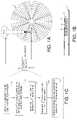
- FIG. 1Ashows a data storage device in the form of a disk drive according to an embodiment comprising a head actuated over a disk.
- FIG. 1Bshows an embodiment wherein the head comprises a write coil configured to excite a write pole to generate a magnetic write field, a write assist element, and a read element.
- FIG. 1Cis a flow diagram according to an embodiment wherein degradation of the write pole is detected based on a noise power measurement of the read signal.
- FIG. 2shows a cross-section of a head according to an embodiment comprising a write assist element (e.g., a laser for HAMR or a STO for MAMR) and a write coil for exciting a write pole.
- a write assist elemente.g., a laser for HAMR or a STO for MAMR
- a write coilfor exciting a write pole.
- FIG. 3Ashows an embodiment wherein a test pattern is written to the magnetic media using a high bias applied to the laser and a high current applied to the write coil.
- FIG. 3Bshows an embodiment wherein the test pattern is read after applying a second bias to the laser while the head passes over the test pattern, wherein a noise power of the resulting read signal is measured.
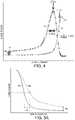
- FIG. 4shows a plot of noise power of the read signal versus a bias current applied to a laser when the current applied to the write coil is approximately zero, and when the current applied to the write coil is a calibrated current that achieves a target capacity of the magnetic media.
- FIG. 5Ashows a plot of the noise power of the read signal versus a write current applied to the write coil, wherein in one embodiment degradation of the write pole is detected by detecting a change in the noise power curve over time.
- FIG. 5Bshows a change over time of the write current required for the noise power to reach fifty percent of its maximum which can indicate degradation of a write pole.
- FIG. 6Ashows an example embodiment of the noise power curve evolving over time when the test pattern is initially written with a DC or low frequency AC pattern and then an overwrite operation applies an opposite magnetic write field to the test pattern.
- FIG. 6Bshows an example embodiment of the noise power curve evolving over time when the test pattern is initially written with a high frequency AC pattern and then an overwrite operation applies a DC magnetic write field.
- FIG. 1Ashows a data storage device in the form of a disk drive according to an embodiment comprising a head 2 actuated over a magnetic media such as a disk 4 , wherein in one embodiment shown in FIG. 1B , the head 2 comprises a write coil 6 configured to excite a write pole to generate a magnetic write field, a write assist element 8 , and a read element 10 .
- a disk driveis used as an illustrative example herein, various embodiments of the invention may be applied to, and/or include, other types of data storage device with magnetic media such as tape drives.
- the disk drivefurther comprises control circuitry 12 configured to execute the flow diagram of FIG.
- a test patternis written to the magnetic media by applying a first current to the write coil (block 14 ).
- a second currentis applied to the write coil while the head passes over the test pattern, wherein the second current has a polarity opposite the first current (block 16 ).
- the test patternis read from the magnetic media using the head to generate a first read signal (block 18 ).
- a first noise power of the first read signalis measured (block 20 ), and degradation of the write pole is detected based on the first noise power measurement (block 22 ).
- FIG. 2shows a cross-sectional view of a suitable head 2 according to an embodiment, wherein the head 2 may comprise more or fewer elements in various other embodiments.
- the head 2comprises write elements 24 configured to write data to the disk surface, and read elements 26 configured to read data from the disk surface.
- the bottom surface of the head 2 facing the disk surfaceis referred to as an air bearing surface (ABS) wherein an air bearing forms between the head 2 and the disk surface due to the disk spinning such that the head 2 effectively flies above the disk surface.
- the read elements 26 of the head 2may comprise a magnetoresistive (MR) read element 28 that is fabricated between MR shields 30 A and 30 B.
- MRmagnetoresistive
- the write elements 24comprise a return pole 32 , a write assist element 34 (e.g., a suitable laser and NFT in HAMR, a STO in MAMR, or a material stack, including conductive materials, used in energy assisted recording) fabricated between a main pole 36 and a trailing shield 38 , and a write coil 40 that excites the main pole 36 to generate a magnetic write field that magnetizes the disk surface, thereby writing data to the disk surface.
- the head 2may also comprise a fly height actuator (FHA) 42 that is biased to achieve a target fly height of the head 2 over the disk surface.
- FHAfly height actuator
- any suitable FHA 42may be employed, such as a suitable thermal actuator that adjusts the fly height through thermal expansion, or a suitable mechanical actuator such as a suitable piezoelectric actuator that adjusts the fly height through mechanical deflection.
- a material stack as the write assist element 34include those described in U.S. Pat. No. 10,366,714, titled “Magnetic write head for providing spin-torque-assisted write field enhancement,” to Olson et al., and in U.S. Pat. No. 10,679,650, titled “Current-assisted magnetic recording write head with improved write gap structure” to Bai et al., both of which are hereby incorporated by reference.
- one or both of the main pole 36 and/or the return pole 32 of the head 2may degrade over time causing a corresponding degradation of the written data. Therefore it is desirable to detect degradation of one or both of the write poles in order to take any suitable corrective action, such as warning the user of an impending failure, convert the corresponding disk surface to “read only,” collect degradation data to improve manufacturing processes, etc.
- the inventorshave discovered there is a relatively high correlation between changes in the noise power of the read signal over time and degradation of one or both of the write poles. Accordingly in one embodiment a noise power of the read signal is periodically measured and degradation of one or both write poles detected based on changes in the noise power measurement.
- a test patternmay be written to the magnetic media using a high temperature (e.g., high bias applied to the write assist element 34 , such as a laser) in order to heat the magnetic media significantly above its mean Curie temperature and a high magnetic field 44 (high current applied to the write coil) in order to initialize the grains of the magnetic media into a predetermined orientation (e.g., all down in the example of FIG. 3A ).
- a high temperaturee.g., high bias applied to the write assist element 34 , such as a laser
- a high magnetic field 44high current applied to the write coil
- the test patternis then subjected to a lower temperature (via a lower bias applied to the write assist element 34 , such as the laser) and a lower magnetic field 46 having a magnetic orientation opposite of the grains as shown in FIG. 3B (i.e., an overwrite operation).
- the read element 10is then used to read the test pattern, and a noise power of the resulting read signal is measured.
- the write assist element 34 in the various embodiments belowwill be referred to as a laser, but the embodiments are not limited to just HAMR as discussed above, as other example write assist elements can similarly be used to generate heat in the media.
- the test patternis “band written” by rewriting the test pattern at a number of radial offsets in order to subject a predetermined band of the magnetic media to the peak media temperature induced by the laser.
- the overwrite operationis executed at a number of radial offsets in order to subject the predetermined band of the magnetic media to the peak media temperature induced by the laser.
- Any suitable test patternmay be written to the magnetic media, such as a DC pattern or an AC pattern, as long as the initial saturated state of the magnetic media is known prior to the overwrite operation.
- the noise power measurement of the read signalmay be made by writing the test pattern as show in FIG. 3A so that the grains have a first magnetic orientation (e.g., all down) prior to the overwrite operation.
- the noise power measurement of the read signalmay also be made by writing the test pattern so that the grains have a second orientation (e.g., all up) prior to the overwrite operation.
- the two noise power measurementsmay then be averaged in order to improve the accuracy of the final measurement.
- the resulting noise power measurement of the read signalis affected primarily by the Curie temperature properties of the magnetic media.
- the bias applied to the laser(laser current in this example) is swept through a range of settings from low to high over a number of corresponding overwrite operations. For each setting of the laser current the overwrite operation of FIG. 3B is executed, and after the overwrite operation the test pattern is read and the noise power of the read signal measured as represented by curve 48 in FIG. 4 .
- at least one parameter of a noise power functionmay then be generated by curve fitting the noise power measurements of curve 48 to the noise power function.
- the grains of the magnetic mediamay be re-initialized such as shown in FIG. 3A prior to each overwrite operation (for each different laser current setting shown in FIG. 4 ).
- the process of generating the noise power measurements shown in FIG. 4may be expedited by performing each overwrite operation without re-initializing the grains of the magnetic media (i.e., in one embodiment the grains may be initialized one time such as shown in FIG. 3A prior to executing a number of the overwrite operations each at an incrementally higher laser current).
- FIG. 4shows an embodiment wherein a noise power curve 50 may be generated for a given non-zero magnetic field 46 (i.e., write current) applied to the magnetic media during the overwrite operation (e.g., as shown in FIG. 3B ). That is, in one embodiment the laser current is adjusted incrementally for each overwrite operation while also applying a given non-zero magnetic field 46 . Based on the resulting noise power curve 50 the average write temperature ⁇ Tw> may be estimated as well as the standard deviation ⁇ Tw of the write temperature (which may be approximated as the peak and the width of the distribution as shown in FIG. 4 ). In one embodiment the noise power may be measured periodically at room temperature (low laser current) for zero write current (curve 48 in FIG.
- a noise power curve 50may be generated for a given non-zero magnetic field 46 (i.e., write current) applied to the magnetic media during the overwrite operation (e.g., as shown in FIG. 3B ). That is, in one embodiment the laser current is adjusted incrementally for each over
- a noise power curvemay be generated relative to the write current applied to the write coil as shown in FIG. 5A , wherein a change in the noise power curve over time may indicate a write pole of the head is degrading.
- the noise power curve shown in FIG. 5Ais generated at a high media temperature (high laser current) that is above the mean Curie temperature of the grains.
- a noise power curve 54may be generated early in the life of the data storage device (e.g., during manufacturing). Periodically over the life of the data storage device the noise power curve may be regenerated (e.g., noise power curve 56 in FIG. 5A ) and compared to the initial noise power curve 54 in order to detect a degradation of a write pole.
- any suitable feature of the noise power curvemay be evaluated in order to detect degradation of a write pole.
- a difference 58 in the write current required for the noise power to reach fifty percent of its maximummay be evaluated, such as detecting when the difference 58 exceeds a threshold, or when a rate of change (slope) of the difference 58 exceeds a threshold.
- FIG. 5Bshows an example of the write current for fifty percent noise power changing over time, wherein the amplitude, change in amplitude, rate of change, etc., may indicate degradation of a write pole.
- a difference 60 in the noise power measurement at a target write current required to at least partially saturate the magnetic mediamay be evaluated, such as detecting when the difference 60 exceeds a threshold, or when a rate of change (slope) of the difference 60 exceeds a threshold.
- the noise power curvesuch as shown in FIG. 5A using a high media temperature (high laser current) above the mean Curie temperature of the grains in HAMR
- it may not be necessary to initialize the grains of the magnetic media into a predetermined orientatione.g., all down in the example of FIG. 3A .
- the low write currentfirst setting of FIG. 5A
- the resulting high media temperaturewill orient the gains randomly such that the noise power of the read signal is maximum. Incrementally increasing the write current as shown in FIG. 5A will then cause the grains to gradually orient into the direction of the magnetic write field causing the noise power to decrease as the write current increases.
- the test patternmay be initialized by writing a DC or AC test pattern using a suitable write current.
- FIG. 6Ashows an example embodiment of the noise power curve evolving over time when the test pattern is initially written with a DC or low frequency AC pattern and then the overwrite operation applies an opposite magnetic write field to the test pattern.
- FIG. 6Bshows an example embodiment of the noise power curve evolving over time when the test pattern is initially written with a high frequency AC pattern and then the overwrite operation applies a DC magnetic write field.
- any suitable conventional techniquemay be employed to measure the noise power of the read signal in the above described embodiments.
- techniques for measuring the noise power of a read signalare disclosed in the technical articles “MEASUREMENTS AND MODELING OF NOISE IN DC-ERASED THIN-FILM MEDIA” by Martin J. Vos, et al., and “DC MODULATION NOISE AND DEMAGNETIZING FIELDS IN THINK METALLIC MEDIA” by Giora J. Tarnopolsky et al., the disclosures of which are incorporated herein by reference.
- control circuitrymay be implemented within a read channel integrated circuit, or in a component separate from the read channel, such as a data storage controller, or certain operations described above may be performed by a read channel and others by a data storage controller.
- the read channel and data storage controllerare implemented as separate integrated circuits, and in an alternative embodiment they are fabricated into a single integrated circuit or system on a chip (SOC).
- the control circuitrymay include a suitable preamp circuit implemented as a separate integrated circuit, integrated into the read channel or data storage controller circuit, or integrated into a SOC.
- control circuitrycomprises a microprocessor executing instructions, the instructions being operable to cause the microprocessor to perform the flow diagrams described herein.
- the instructionsmay be stored in any computer-readable medium. In one embodiment, they may be stored on a non-volatile semiconductor memory external to the microprocessor, or integrated with the microprocessor in a SOC. In another embodiment, the instructions are stored on the disk and read into a volatile semiconductor memory when the disk drive is powered on. In yet another embodiment, the control circuitry comprises suitable logic circuitry, such as state machine circuitry.
- At least some of the flow diagram blocksmay be implemented using analog circuitry (e.g., analog comparators, timers, etc.), and in other embodiments at least some of the blocks may be implemented using digital circuitry or a combination of analog/digital circuitry.
- analog circuitrye.g., analog comparators, timers, etc.
- digital circuitrye.g., digital comparators, timers, etc.
- a disk drivemay include a magnetic disk drive, an optical disk drive, a hybrid disk drive, etc.
- some embodimentsmay include electronic devices such as computing devices, data server devices, media content storage devices, etc. that comprise the storage media and/or control circuitry as described above.
Landscapes
- Engineering & Computer Science (AREA)
- Manufacturing & Machinery (AREA)
- Digital Magnetic Recording (AREA)
Abstract
Description
Claims (23)
Priority Applications (1)
| Application Number | Priority Date | Filing Date | Title |
|---|---|---|---|
| US17/176,302US11423939B1 (en) | 2021-02-16 | 2021-02-16 | Data storage device detecting write pole degradation for magnetic write head |
Applications Claiming Priority (1)
| Application Number | Priority Date | Filing Date | Title |
|---|---|---|---|
| US17/176,302US11423939B1 (en) | 2021-02-16 | 2021-02-16 | Data storage device detecting write pole degradation for magnetic write head |
Publications (2)
| Publication Number | Publication Date |
|---|---|
| US20220262401A1 US20220262401A1 (en) | 2022-08-18 |
| US11423939B1true US11423939B1 (en) | 2022-08-23 |
Family
ID=82800572
Family Applications (1)
| Application Number | Title | Priority Date | Filing Date |
|---|---|---|---|
| US17/176,302ActiveUS11423939B1 (en) | 2021-02-16 | 2021-02-16 | Data storage device detecting write pole degradation for magnetic write head |
Country Status (1)
| Country | Link |
|---|---|
| US (1) | US11423939B1 (en) |
Cited By (1)
| Publication number | Priority date | Publication date | Assignee | Title |
|---|---|---|---|---|
| US12159653B1 (en) | 2023-06-28 | 2024-12-03 | Western Digital Technologies, Inc. | Data storage device with laser write bias optimization using disk thermal-magnetic response mapping in heat-assisted magnetic recording |
Citations (15)
| Publication number | Priority date | Publication date | Assignee | Title |
|---|---|---|---|---|
| US6166536A (en) | 1997-12-11 | 2000-12-26 | Seagate Technology Llc | System and method for measuring erase band widths on magnetic media |
| US6304081B1 (en) | 1997-12-11 | 2001-10-16 | Seagate Technology Llc | System and method for non-destructive measurement of dynamic coercivity effects |
| US8908483B1 (en) | 2014-05-30 | 2014-12-09 | HGST Netherlands B.V. | Implementing contact sensing with near field transducer (NFT) and in-drive NFT characterization diagnostics in heat-assisted magnetic recording (HAMR) HDD |
| US8929186B1 (en)* | 2013-02-11 | 2015-01-06 | Western Digital Technologies, Inc. | Disk drive calibrating laser power for heat assisted magnetic recording based on quality metric and track width |
| US9183859B1 (en)* | 2014-11-11 | 2015-11-10 | Western Digital (Fremont), Llc | HAMR writer pole length characterization |
| US9396750B2 (en) | 2014-02-20 | 2016-07-19 | Seagate Technology Llc | Near-field transducer efficiency monitoring system |
| US9837118B1 (en) | 2017-03-02 | 2017-12-05 | Seagate Technology Llc | Determining thermal gradient of heat-assisted magnetic recording hotspot based on timing errors |
| US10043540B1 (en) | 2016-08-23 | 2018-08-07 | Seagate Technology Llc | Health monitoring for head of a heat-magnetic recording device using a writer-reader offset |
| US10147454B1 (en) | 2017-05-15 | 2018-12-04 | Seagate Technology Llc | Heat-assisted magnetic recording device capable of detecting degradation of NFT by measuring back-heat from medium |
| US10339963B1 (en) | 2018-07-02 | 2019-07-02 | Seagate Technology Llc | Determining thermal gradient of a HAMR hotspot using pseudo-random bit sequences recorded at a stepped laser power |
| US20190371362A1 (en)* | 2018-05-30 | 2019-12-05 | Western Digital Technologies, Inc. | Data storage device calibrating data density based on amplitude-inverted or time-inverted read signal |
| US10672419B1 (en)* | 2018-11-30 | 2020-06-02 | Kabushiki Kaisha Toshiba | Magnetic recording and reading apparatus and magnetic recording method |
| US10699736B1 (en) | 2019-07-22 | 2020-06-30 | Western Digital Technologies, Inc. | Data storage device detecting abnormality with a write assist element based on slope of protrusion |
| US10878844B1 (en)* | 2020-03-12 | 2020-12-29 | Western Digital Technologies, Inc. | Data storage device controlling head fly height based on temperature |
| US11257525B1 (en)* | 2021-02-16 | 2022-02-22 | Western Digital Technologies, Inc. | Data storage device predicting failure of near field transducer based on slope of thermal gradient |
- 2021
- 2021-02-16USUS17/176,302patent/US11423939B1/enactiveActive
Patent Citations (15)
| Publication number | Priority date | Publication date | Assignee | Title |
|---|---|---|---|---|
| US6304081B1 (en) | 1997-12-11 | 2001-10-16 | Seagate Technology Llc | System and method for non-destructive measurement of dynamic coercivity effects |
| US6166536A (en) | 1997-12-11 | 2000-12-26 | Seagate Technology Llc | System and method for measuring erase band widths on magnetic media |
| US8929186B1 (en)* | 2013-02-11 | 2015-01-06 | Western Digital Technologies, Inc. | Disk drive calibrating laser power for heat assisted magnetic recording based on quality metric and track width |
| US9396750B2 (en) | 2014-02-20 | 2016-07-19 | Seagate Technology Llc | Near-field transducer efficiency monitoring system |
| US8908483B1 (en) | 2014-05-30 | 2014-12-09 | HGST Netherlands B.V. | Implementing contact sensing with near field transducer (NFT) and in-drive NFT characterization diagnostics in heat-assisted magnetic recording (HAMR) HDD |
| US9183859B1 (en)* | 2014-11-11 | 2015-11-10 | Western Digital (Fremont), Llc | HAMR writer pole length characterization |
| US10043540B1 (en) | 2016-08-23 | 2018-08-07 | Seagate Technology Llc | Health monitoring for head of a heat-magnetic recording device using a writer-reader offset |
| US9837118B1 (en) | 2017-03-02 | 2017-12-05 | Seagate Technology Llc | Determining thermal gradient of heat-assisted magnetic recording hotspot based on timing errors |
| US10147454B1 (en) | 2017-05-15 | 2018-12-04 | Seagate Technology Llc | Heat-assisted magnetic recording device capable of detecting degradation of NFT by measuring back-heat from medium |
| US20190371362A1 (en)* | 2018-05-30 | 2019-12-05 | Western Digital Technologies, Inc. | Data storage device calibrating data density based on amplitude-inverted or time-inverted read signal |
| US10339963B1 (en) | 2018-07-02 | 2019-07-02 | Seagate Technology Llc | Determining thermal gradient of a HAMR hotspot using pseudo-random bit sequences recorded at a stepped laser power |
| US10672419B1 (en)* | 2018-11-30 | 2020-06-02 | Kabushiki Kaisha Toshiba | Magnetic recording and reading apparatus and magnetic recording method |
| US10699736B1 (en) | 2019-07-22 | 2020-06-30 | Western Digital Technologies, Inc. | Data storage device detecting abnormality with a write assist element based on slope of protrusion |
| US10878844B1 (en)* | 2020-03-12 | 2020-12-29 | Western Digital Technologies, Inc. | Data storage device controlling head fly height based on temperature |
| US11257525B1 (en)* | 2021-02-16 | 2022-02-22 | Western Digital Technologies, Inc. | Data storage device predicting failure of near field transducer based on slope of thermal gradient |
Non-Patent Citations (8)
| Title |
|---|
| G. J. Tarnopolsky, L. T. Tran, A. M. Barany, H. N. Bertram and D. R. Bloomquist, "DC modulation noise and demagnetizing fields in thin metallic media," in IEEE Transactions on Magnetics, vol. 25, No. 4, pp. 3160-3165, Jul. 1989. |
| H. J. Richter, C. C. Poon, G. Parker, M. Staffaroni, O. Mosendz, R. Zakai, and B. C. Stipe, "Direct Measurement of the Thermal Gradient in Heat Assisted Magnetic Recording," in IEEE Transactions on Magnetics, vol. 49, No. 10, pp. 5378-5381, Oct. 2013. |
| Hai Li, "Storage Physics and Noise Mechanism in Heat-Assisted Magnetic Recording," Carnegie Mellon University. Thesis. Sep. 2016. https://doi.org/10.1184/R1/6723209.v1. |
| I. Gilbert, D. A. Saunders, P. Czoschke, Z. Liu, S. Granz and T. Rausch, "Measuring Cross-Track Thermal Gradient in Heat-Assisted Magnetic Recording," in IEEE Transactions on Magnetics, vol. 55, No. 12, pp. 1-5, Dec. 2019. |
| I. Gilbert, Z. Liu, X. Zheng, S. Granz, W. Eppler and T. Rausch, "Measuring Thermal Gradient in HAMR Using Pseudorandom Bit Sequences," in IEEE Transactions on Magnetics, vol. 55, No. 3, pp. 1-6, Mar. 2019. |
| M. J. Vos, Y. Tanaka and J. H. Judy, "Measurements and modelling of noise in DC-erased thin-film media," in IEEE Transactions on Magnetics, vol. 26, No. 5, pp. 2149-2151, Sep. 1990. |
| Shaomin Xiong, Robert Smith, Jian Xu, Shuji Nishida, Masaru Furukawa, Kenji Tasaka, Kenji Kuroki, Yeoungchin Yoon, Na Wang, Sripathi Canchi, Erhard Schreck, and Qing Dai, "Setting Write Spacing in Heat Assisted Magnetic Recording," in IEEE Transactions on Magnetics, vol. 54, No. 8, pp. 1-7, Aug. 2018. |
| T. D. Trinh, S. Rajauria, R. Smith, E. Schreck, Q. Dai and F. E. Talke, "Temperature-Induced Near-Field Transducer Failure in Heat-Assisted Magnetic Recording," in IEEE Transactions on Magnetics, vol. 56, No. 6, pp. 1-4, Jun. 2020. |
Cited By (1)
| Publication number | Priority date | Publication date | Assignee | Title |
|---|---|---|---|---|
| US12159653B1 (en) | 2023-06-28 | 2024-12-03 | Western Digital Technologies, Inc. | Data storage device with laser write bias optimization using disk thermal-magnetic response mapping in heat-assisted magnetic recording |
Also Published As
| Publication number | Publication date |
|---|---|
| US20220262401A1 (en) | 2022-08-18 |
Similar Documents
| Publication | Publication Date | Title |
|---|---|---|
| US8094396B1 (en) | Media defect scan | |
| US8787125B1 (en) | Disk drive calibrating fly height actuator to enable laser biasing during non-write mode | |
| US7804657B1 (en) | Setting an operating bias current for a magnetoresistive head using ratio of target voltage and measured voltage | |
| US10699736B1 (en) | Data storage device detecting abnormality with a write assist element based on slope of protrusion | |
| US8643967B2 (en) | Magnetic disk drive and microwave assisted recording method | |
| US9305584B2 (en) | Determining oscillation characteristic for high-frequency assisted magnetic recording device | |
| US11257525B1 (en) | Data storage device predicting failure of near field transducer based on slope of thermal gradient | |
| US8922929B1 (en) | Disk drive calibrating fly height actuator and laser power for heat assisted magnetic recording | |
| US8976633B1 (en) | Data storage device calibrating fly height actuator based on laser power for heat assisted magnetic recording | |
| US10014009B1 (en) | Magnetic disk drive and recording head control method | |
| CN111276165B (en) | Data storage device for pre-biasing a rotational torque oscillator prior to a write operation | |
| US9123370B1 (en) | Data storage device calibrating fly height actuator based on laser power for heat assisted magnetic recording | |
| US11990161B2 (en) | Data storage device pre-biasing write current for energy assisted magnetic recording | |
| JP3996785B2 (en) | Apparatus and method for recovering disk drive instability head | |
| US11276432B1 (en) | Data storage device measuring HAMR media distributions | |
| JP2007250162A (en) | Media drive apparatus and control method thereof | |
| US11423939B1 (en) | Data storage device detecting write pole degradation for magnetic write head | |
| US9472219B1 (en) | Data storage device calibrating parameter for heat assisted magnetic recording | |
| US9953674B2 (en) | Characterizing a sensing circuit of a data storage device | |
| US10783913B1 (en) | Data storage device measuring air bearing resonant frequency to calibrate fly height touchdown power | |
| US10566014B2 (en) | Data storage device detecting resistance delta of a spin torque oscillator | |
| US11430482B1 (en) | Data storage device detecting NFT contamination by measuring thermal gradient and magnetic write width | |
| CN115938401B (en) | Magnetic disk device and recording format changing method | |
| US11404079B1 (en) | Data storage device writing to defective data sector for fly height control | |
| US20120147498A1 (en) | Head ic and magnetic disk apparatus having microwave assistance function |
Legal Events
| Date | Code | Title | Description |
|---|---|---|---|
| AS | Assignment | Owner name:WESTERN DIGITAL TECHNOLOGIES, INC., CALIFORNIA Free format text:ASSIGNMENT OF ASSIGNORS INTEREST;ASSIGNORS:JUBERT, PIERRE-OLIVIER;RAJAURIA, SUKUMAR;REEL/FRAME:055268/0626 Effective date:20210210 | |
| FEPP | Fee payment procedure | Free format text:ENTITY STATUS SET TO UNDISCOUNTED (ORIGINAL EVENT CODE: BIG.); ENTITY STATUS OF PATENT OWNER: LARGE ENTITY | |
| AS | Assignment | Owner name:JPMORGAN CHASE BANK, N.A., AS AGENT, ILLINOIS Free format text:SECURITY INTEREST;ASSIGNOR:WESTERN DIGITAL TECHNOLOGIES, INC.;REEL/FRAME:056285/0292 Effective date:20210507 | |
| AS | Assignment | Owner name:WESTERN DIGITAL TECHNOLOGIES, INC., CALIFORNIA Free format text:RELEASE OF SECURITY INTEREST AT REEL 056285 FRAME 0292;ASSIGNOR:JPMORGAN CHASE BANK, N.A.;REEL/FRAME:058982/0001 Effective date:20220203 | |
| STCF | Information on status: patent grant | Free format text:PATENTED CASE | |
| AS | Assignment | Owner name:JPMORGAN CHASE BANK, N.A., ILLINOIS Free format text:PATENT COLLATERAL AGREEMENT - A&R LOAN AGREEMENT;ASSIGNOR:WESTERN DIGITAL TECHNOLOGIES, INC.;REEL/FRAME:064715/0001 Effective date:20230818 Owner name:JPMORGAN CHASE BANK, N.A., ILLINOIS Free format text:PATENT COLLATERAL AGREEMENT - DDTL LOAN AGREEMENT;ASSIGNOR:WESTERN DIGITAL TECHNOLOGIES, INC.;REEL/FRAME:067045/0156 Effective date:20230818 |