US11423807B2 - Universal branding panel - Google Patents
Universal branding panelDownload PDFInfo
- Publication number
- US11423807B2 US11423807B2US16/778,419US202016778419AUS11423807B2US 11423807 B2US11423807 B2US 11423807B2US 202016778419 AUS202016778419 AUS 202016778419AUS 11423807 B2US11423807 B2US 11423807B2
- Authority
- US
- United States
- Prior art keywords
- housing
- faceplate
- branding
- computing infrastructure
- retention features
- Prior art date
- Legal status (The legal status is an assumption and is not a legal conclusion. Google has not performed a legal analysis and makes no representation as to the accuracy of the status listed.)
- Active, expires
Links
Images


Classifications
- G—PHYSICS
- G09—EDUCATION; CRYPTOGRAPHY; DISPLAY; ADVERTISING; SEALS
- G09F—DISPLAYING; ADVERTISING; SIGNS; LABELS OR NAME-PLATES; SEALS
- G09F3/00—Labels, tag tickets, or similar identification or indication means; Seals; Postage or like stamps
- G09F3/02—Forms or constructions
- G—PHYSICS
- G09—EDUCATION; CRYPTOGRAPHY; DISPLAY; ADVERTISING; SEALS
- G09F—DISPLAYING; ADVERTISING; SIGNS; LABELS OR NAME-PLATES; SEALS
- G09F13/00—Illuminated signs; Luminous advertising
- G09F13/20—Illuminated signs; Luminous advertising with luminescent surfaces or parts
- G09F13/22—Illuminated signs; Luminous advertising with luminescent surfaces or parts electroluminescent
- G—PHYSICS
- G09—EDUCATION; CRYPTOGRAPHY; DISPLAY; ADVERTISING; SEALS
- G09F—DISPLAYING; ADVERTISING; SIGNS; LABELS OR NAME-PLATES; SEALS
- G09F3/00—Labels, tag tickets, or similar identification or indication means; Seals; Postage or like stamps
- G09F3/04—Labels, tag tickets, or similar identification or indication means; Seals; Postage or like stamps to be fastened or secured by the material of the label itself, e.g. by thermo-adhesion
- G—PHYSICS
- G09—EDUCATION; CRYPTOGRAPHY; DISPLAY; ADVERTISING; SEALS
- G09F—DISPLAYING; ADVERTISING; SIGNS; LABELS OR NAME-PLATES; SEALS
- G09F7/00—Signs, name or number plates, letters, numerals, or symbols; Panels or boards
- G09F7/02—Signs, plates, panels or boards using readily-detachable elements bearing or forming symbols
- G09F7/06—Signs, plates, panels or boards using readily-detachable elements bearing or forming symbols the elements being secured or adapted to be secured by means of pins and holes
- G—PHYSICS
- G09—EDUCATION; CRYPTOGRAPHY; DISPLAY; ADVERTISING; SEALS
- G09F—DISPLAYING; ADVERTISING; SIGNS; LABELS OR NAME-PLATES; SEALS
- G09F13/00—Illuminated signs; Luminous advertising
- G09F13/20—Illuminated signs; Luminous advertising with luminescent surfaces or parts
- G09F13/22—Illuminated signs; Luminous advertising with luminescent surfaces or parts electroluminescent
- G09F2013/222—Illuminated signs; Luminous advertising with luminescent surfaces or parts electroluminescent with LEDs
Definitions
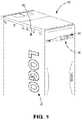
- FIG. 1is a perspective view of a computing infrastructure device with a conventional branding panel installed thereon;
Landscapes
- Physics & Mathematics (AREA)
- General Physics & Mathematics (AREA)
- Engineering & Computer Science (AREA)
- Theoretical Computer Science (AREA)
- Pinball Game Machines (AREA)
- Casings For Electric Apparatus (AREA)
Abstract
Description
Claims (20)
Priority Applications (1)
| Application Number | Priority Date | Filing Date | Title |
|---|---|---|---|
| US16/778,419US11423807B2 (en) | 2016-12-29 | 2020-01-31 | Universal branding panel |
Applications Claiming Priority (2)
| Application Number | Priority Date | Filing Date | Title |
|---|---|---|---|
| US15/393,930US10586471B1 (en) | 2016-12-29 | 2016-12-29 | Universal branding panel |
| US16/778,419US11423807B2 (en) | 2016-12-29 | 2020-01-31 | Universal branding panel |
Related Parent Applications (1)
| Application Number | Title | Priority Date | Filing Date |
|---|---|---|---|
| US15/393,930ContinuationUS10586471B1 (en) | 2016-12-29 | 2016-12-29 | Universal branding panel |
Publications (2)
| Publication Number | Publication Date |
|---|---|
| US20200168128A1 US20200168128A1 (en) | 2020-05-28 |
| US11423807B2true US11423807B2 (en) | 2022-08-23 |
Family
ID=69723693
Family Applications (2)
| Application Number | Title | Priority Date | Filing Date |
|---|---|---|---|
| US15/393,930Active2037-05-27US10586471B1 (en) | 2016-12-29 | 2016-12-29 | Universal branding panel |
| US16/778,419Active2037-03-23US11423807B2 (en) | 2016-12-29 | 2020-01-31 | Universal branding panel |
Family Applications Before (1)
| Application Number | Title | Priority Date | Filing Date |
|---|---|---|---|
| US15/393,930Active2037-05-27US10586471B1 (en) | 2016-12-29 | 2016-12-29 | Universal branding panel |
Country Status (1)
| Country | Link |
|---|---|
| US (2) | US10586471B1 (en) |
Families Citing this family (1)
| Publication number | Priority date | Publication date | Assignee | Title |
|---|---|---|---|---|
| US10586471B1 (en) | 2016-12-29 | 2020-03-10 | VCE IP Holding Company LLC | Universal branding panel |
Citations (24)
| Publication number | Priority date | Publication date | Assignee | Title |
|---|---|---|---|---|
| US2245885A (en) | 1939-03-20 | 1941-06-17 | Door Glow Lite Company | Lighting device |
| US2881306A (en) | 1953-12-01 | 1959-04-07 | Percival H Sherron | Illuminated outdoor telephone booth |
| US2934590A (en)* | 1958-08-29 | 1960-04-26 | Harry B Thompson | Electric outlet receptacle |
| US4063660A (en)* | 1977-04-06 | 1977-12-20 | Ware Fuse Corporation | Electrical outlet box |
| US4848017A (en) | 1987-08-07 | 1989-07-18 | Bailey James M | Illuminated building number assembly |
| US5450221A (en)* | 1993-09-08 | 1995-09-12 | Delco Electronics Corporation | Compact liquid crystal display for instrument panel having a wrap around flexible printed circuit board and translucent web |
| US5515237A (en)* | 1991-10-14 | 1996-05-07 | Kabushiki Kaisha Toshiba | Portable electronic apparatus having a removable hard disk drive including an externally operable lock member |
| US5715136A (en)* | 1996-05-07 | 1998-02-03 | Intime Products Llc | Removable/adjustable digital display accessory for computers |
| US5778479A (en)* | 1996-08-27 | 1998-07-14 | Raia; Lawrence A. | Modular, multiple paint brush system |
| US5778579A (en)* | 1995-06-27 | 1998-07-14 | Yuen; Shu Wing | Illuminated house number |
| US5783777A (en)* | 1996-09-20 | 1998-07-21 | Adtran, Inc. | Dummy front panel face plate for closing electronic circuit card insertion opening in front panel of digital terminal channel bank |
| US6570770B1 (en)* | 2000-06-05 | 2003-05-27 | Power-One, Inc. | Handle integrating mechanical functions with electronic status indicators and adjustment feature |
| US20030163940A1 (en)* | 2002-03-01 | 2003-09-04 | Mautz Timothy E. | Universal snap-in-place customer label plate |
| US6686540B2 (en)* | 2000-06-08 | 2004-02-03 | Carlo Compagnone, Jr. | Temporary protective cover for an electrical box |
| US7255466B2 (en)* | 2005-05-17 | 2007-08-14 | Lear Corporation | Illuminated keyless entry control device |
| US7338140B1 (en)* | 2007-02-18 | 2008-03-04 | Compucase Enterprise Co., Ltd. | Computer housing |
| US7424785B2 (en)* | 2004-12-20 | 2008-09-16 | Emc Corporation | Label cassette for an electronics enclosure |
| US8077452B2 (en)* | 2008-08-26 | 2011-12-13 | Aopen Inc. | Face panel for a computer housing |
| US20130180139A1 (en)* | 2011-07-05 | 2013-07-18 | Jeffrey L. Underwood | Electrical outlet cover plate with signage feature |
| US9215824B2 (en)* | 2013-07-17 | 2015-12-15 | Shenzhen Treasure City Technology Co., Ltd. | Server and indicating tag of the same |
| US9655268B2 (en)* | 2014-10-09 | 2017-05-16 | E.G.O. Elektro-Geraetebau Gmbh | Operating control unit for an electrical appliance and electrical appliance |
| US10401081B2 (en)* | 2017-10-13 | 2019-09-03 | Whirlpool Corporation | Adapter crossbar for appliance user interface |
| US10586471B1 (en) | 2016-12-29 | 2020-03-10 | VCE IP Holding Company LLC | Universal branding panel |
| US11019746B1 (en)* | 2020-03-09 | 2021-05-25 | Whirlpool Corporation | Lateral alignment system for an appliance control panel assembly and method |
- 2016
- 2016-12-29USUS15/393,930patent/US10586471B1/enactiveActive
- 2020
- 2020-01-31USUS16/778,419patent/US11423807B2/enactiveActive
Patent Citations (24)
| Publication number | Priority date | Publication date | Assignee | Title |
|---|---|---|---|---|
| US2245885A (en) | 1939-03-20 | 1941-06-17 | Door Glow Lite Company | Lighting device |
| US2881306A (en) | 1953-12-01 | 1959-04-07 | Percival H Sherron | Illuminated outdoor telephone booth |
| US2934590A (en)* | 1958-08-29 | 1960-04-26 | Harry B Thompson | Electric outlet receptacle |
| US4063660A (en)* | 1977-04-06 | 1977-12-20 | Ware Fuse Corporation | Electrical outlet box |
| US4848017A (en) | 1987-08-07 | 1989-07-18 | Bailey James M | Illuminated building number assembly |
| US5515237A (en)* | 1991-10-14 | 1996-05-07 | Kabushiki Kaisha Toshiba | Portable electronic apparatus having a removable hard disk drive including an externally operable lock member |
| US5450221A (en)* | 1993-09-08 | 1995-09-12 | Delco Electronics Corporation | Compact liquid crystal display for instrument panel having a wrap around flexible printed circuit board and translucent web |
| US5778579A (en)* | 1995-06-27 | 1998-07-14 | Yuen; Shu Wing | Illuminated house number |
| US5715136A (en)* | 1996-05-07 | 1998-02-03 | Intime Products Llc | Removable/adjustable digital display accessory for computers |
| US5778479A (en)* | 1996-08-27 | 1998-07-14 | Raia; Lawrence A. | Modular, multiple paint brush system |
| US5783777A (en)* | 1996-09-20 | 1998-07-21 | Adtran, Inc. | Dummy front panel face plate for closing electronic circuit card insertion opening in front panel of digital terminal channel bank |
| US6570770B1 (en)* | 2000-06-05 | 2003-05-27 | Power-One, Inc. | Handle integrating mechanical functions with electronic status indicators and adjustment feature |
| US6686540B2 (en)* | 2000-06-08 | 2004-02-03 | Carlo Compagnone, Jr. | Temporary protective cover for an electrical box |
| US20030163940A1 (en)* | 2002-03-01 | 2003-09-04 | Mautz Timothy E. | Universal snap-in-place customer label plate |
| US7424785B2 (en)* | 2004-12-20 | 2008-09-16 | Emc Corporation | Label cassette for an electronics enclosure |
| US7255466B2 (en)* | 2005-05-17 | 2007-08-14 | Lear Corporation | Illuminated keyless entry control device |
| US7338140B1 (en)* | 2007-02-18 | 2008-03-04 | Compucase Enterprise Co., Ltd. | Computer housing |
| US8077452B2 (en)* | 2008-08-26 | 2011-12-13 | Aopen Inc. | Face panel for a computer housing |
| US20130180139A1 (en)* | 2011-07-05 | 2013-07-18 | Jeffrey L. Underwood | Electrical outlet cover plate with signage feature |
| US9215824B2 (en)* | 2013-07-17 | 2015-12-15 | Shenzhen Treasure City Technology Co., Ltd. | Server and indicating tag of the same |
| US9655268B2 (en)* | 2014-10-09 | 2017-05-16 | E.G.O. Elektro-Geraetebau Gmbh | Operating control unit for an electrical appliance and electrical appliance |
| US10586471B1 (en) | 2016-12-29 | 2020-03-10 | VCE IP Holding Company LLC | Universal branding panel |
| US10401081B2 (en)* | 2017-10-13 | 2019-09-03 | Whirlpool Corporation | Adapter crossbar for appliance user interface |
| US11019746B1 (en)* | 2020-03-09 | 2021-05-25 | Whirlpool Corporation | Lateral alignment system for an appliance control panel assembly and method |
Non-Patent Citations (8)
| Title |
|---|
| Advisory Action for U.S. Appl. No. 15/393,930 (dated Dec. 12, 2018). |
| Advisory Action for U.S. Appl. No. 15/393,930 (dated Oct. 25, 2019). |
| Commonly-Assigned, co-pending U.S. Appl. No. 15/393,930 for "Universal Branding Panel," (Unpublished, filed Dec. 29, 2016). |
| Final Office Action for U.S. Appl. No. 15/393,930 (dated Aug. 16, 2019). |
| Final Office Action for U.S. Appl. No. 15/393,930 (dated Oct. 4, 2018). |
| Non-Final Office Action for U.S. Appl. No. 15/393,930 (dated Feb. 26, 2019). |
| Non-Final Office Action for U.S. Appl. No. 15/393,930 (dated Jul. 27, 2018). |
| Notice of Allowance and Fee(s) Due for U.S. Appl. No. 15/393,930 (dated Dec. 10, 2019). |
Also Published As
| Publication number | Publication date |
|---|---|
| US10586471B1 (en) | 2020-03-10 |
| US20200168128A1 (en) | 2020-05-28 |
Similar Documents
| Publication | Publication Date | Title |
|---|---|---|
| EP3772875B1 (en) | Printed circuit board mounting structure and display apparatus including the same | |
| US7086769B1 (en) | LED signage device | |
| US7727009B2 (en) | Panel mount light emitting element assembly | |
| AU2014243387B9 (en) | Key module for a keyboard key and method for producing a key module for a keyboard key | |
| US7296908B1 (en) | Housing with releasable front and back portions with electrical connection means | |
| US11423807B2 (en) | Universal branding panel | |
| CN101604583B (en) | Electronic device and manufacturing method thereof | |
| KR101992718B1 (en) | Display apparatus | |
| AU2020260521A1 (en) | Chassis connector | |
| US20030035300A1 (en) | Theft resistant lamp bracket | |
| CN203964521U (en) | A kind of identification light for refrigerator and the refrigerator that comprises it | |
| US20140237871A1 (en) | Apparatus pertaining to physically-discrete sign components | |
| US11009198B2 (en) | Wall lamp | |
| EP0642688B1 (en) | Vending machine with selection panel assembly | |
| CN203797439U (en) | Light source strip-shaped lamp structure | |
| US6685351B2 (en) | Indicator light device of a computer front panel | |
| US20200196474A1 (en) | Electronic badge and housing for the same | |
| KR101041976B1 (en) | Advertising signboard | |
| US20160268071A1 (en) | Wall plate assemblies for identifying electrical devices | |
| KR20080078107A (en) | Lightbox with LED for easy exchange of ad sheets | |
| US20090185345A1 (en) | Computer Module Replacement of Digital Signage | |
| CN107104013B (en) | Key and electronic product | |
| JP3663530B2 (en) | Fire receiver | |
| JP2007175121A (en) | Illuminating device in game machine | |
| CN220541313U (en) | Display mounting structure of air conditioner panel |
Legal Events
| Date | Code | Title | Description |
|---|---|---|---|
| FEPP | Fee payment procedure | Free format text:ENTITY STATUS SET TO UNDISCOUNTED (ORIGINAL EVENT CODE: BIG.); ENTITY STATUS OF PATENT OWNER: LARGE ENTITY | |
| STPP | Information on status: patent application and granting procedure in general | Free format text:DOCKETED NEW CASE - READY FOR EXAMINATION | |
| AS | Assignment | Owner name:THE BANK OF NEW YORK MELLON TRUST COMPANY, N.A., TEXAS Free format text:SECURITY AGREEMENT;ASSIGNORS:CREDANT TECHNOLOGIES INC.;DELL INTERNATIONAL L.L.C.;DELL MARKETING L.P.;AND OTHERS;REEL/FRAME:053546/0001 Effective date:20200409 | |
| AS | Assignment | Owner name:VCE IP HOLDING COMPANY LLC, TEXAS Free format text:ASSIGNMENT OF ASSIGNORS INTEREST;ASSIGNOR:MARRS, SAMUEL MAXWELL;REEL/FRAME:053088/0942 Effective date:20161222 | |
| AS | Assignment | Owner name:EMC IP HOLDING COMPANY LLC, TEXAS Free format text:MERGER;ASSIGNOR:VCE IP HOLDING COMPANY LLC;REEL/FRAME:054178/0942 Effective date:20200128 | |
| STPP | Information on status: patent application and granting procedure in general | Free format text:NON FINAL ACTION MAILED | |
| STPP | Information on status: patent application and granting procedure in general | Free format text:RESPONSE TO NON-FINAL OFFICE ACTION ENTERED AND FORWARDED TO EXAMINER | |
| STPP | Information on status: patent application and granting procedure in general | Free format text:FINAL REJECTION MAILED | |
| STPP | Information on status: patent application and granting procedure in general | Free format text:DOCKETED NEW CASE - READY FOR EXAMINATION | |
| STPP | Information on status: patent application and granting procedure in general | Free format text:NON FINAL ACTION MAILED | |
| STPP | Information on status: patent application and granting procedure in general | Free format text:RESPONSE TO NON-FINAL OFFICE ACTION ENTERED AND FORWARDED TO EXAMINER | |
| AS | Assignment | Owner name:DELL MARKETING L.P. (ON BEHALF OF ITSELF AND AS SUCCESSOR-IN-INTEREST TO CREDANT TECHNOLOGIES, INC.), TEXAS Free format text:RELEASE OF SECURITY INTEREST IN PATENTS PREVIOUSLY RECORDED AT REEL/FRAME (053546/0001);ASSIGNOR:THE BANK OF NEW YORK MELLON TRUST COMPANY, N.A., AS NOTES COLLATERAL AGENT;REEL/FRAME:071642/0001 Effective date:20220329 Owner name:DELL INTERNATIONAL L.L.C., TEXAS Free format text:RELEASE OF SECURITY INTEREST IN PATENTS PREVIOUSLY RECORDED AT REEL/FRAME (053546/0001);ASSIGNOR:THE BANK OF NEW YORK MELLON TRUST COMPANY, N.A., AS NOTES COLLATERAL AGENT;REEL/FRAME:071642/0001 Effective date:20220329 Owner name:DELL PRODUCTS L.P., TEXAS Free format text:RELEASE OF SECURITY INTEREST IN PATENTS PREVIOUSLY RECORDED AT REEL/FRAME (053546/0001);ASSIGNOR:THE BANK OF NEW YORK MELLON TRUST COMPANY, N.A., AS NOTES COLLATERAL AGENT;REEL/FRAME:071642/0001 Effective date:20220329 Owner name:DELL USA L.P., TEXAS Free format text:RELEASE OF SECURITY INTEREST IN PATENTS PREVIOUSLY RECORDED AT REEL/FRAME (053546/0001);ASSIGNOR:THE BANK OF NEW YORK MELLON TRUST COMPANY, N.A., AS NOTES COLLATERAL AGENT;REEL/FRAME:071642/0001 Effective date:20220329 Owner name:EMC CORPORATION, MASSACHUSETTS Free format text:RELEASE OF SECURITY INTEREST IN PATENTS PREVIOUSLY RECORDED AT REEL/FRAME (053546/0001);ASSIGNOR:THE BANK OF NEW YORK MELLON TRUST COMPANY, N.A., AS NOTES COLLATERAL AGENT;REEL/FRAME:071642/0001 Effective date:20220329 Owner name:DELL MARKETING CORPORATION (SUCCESSOR-IN-INTEREST TO FORCE10 NETWORKS, INC. AND WYSE TECHNOLOGY L.L.C.), TEXAS Free format text:RELEASE OF SECURITY INTEREST IN PATENTS PREVIOUSLY RECORDED AT REEL/FRAME (053546/0001);ASSIGNOR:THE BANK OF NEW YORK MELLON TRUST COMPANY, N.A., AS NOTES COLLATERAL AGENT;REEL/FRAME:071642/0001 Effective date:20220329 Owner name:EMC IP HOLDING COMPANY LLC, TEXAS Free format text:RELEASE OF SECURITY INTEREST IN PATENTS PREVIOUSLY RECORDED AT REEL/FRAME (053546/0001);ASSIGNOR:THE BANK OF NEW YORK MELLON TRUST COMPANY, N.A., AS NOTES COLLATERAL AGENT;REEL/FRAME:071642/0001 Effective date:20220329 | |
| STPP | Information on status: patent application and granting procedure in general | Free format text:PUBLICATIONS -- ISSUE FEE PAYMENT VERIFIED | |
| STCF | Information on status: patent grant | Free format text:PATENTED CASE |