US11420690B2 - Aerodynamic skirt securing connector with angular assembly capability - Google Patents
Aerodynamic skirt securing connector with angular assembly capabilityDownload PDFInfo
- Publication number
- US11420690B2 US11420690B2US16/832,678US202016832678AUS11420690B2US 11420690 B2US11420690 B2US 11420690B2US 202016832678 AUS202016832678 AUS 202016832678AUS 11420690 B2US11420690 B2US 11420690B2
- Authority
- US
- United States
- Prior art keywords
- trailer
- skirt
- securing
- strut
- connector assembly
- Prior art date
- Legal status (The legal status is an assumption and is not a legal conclusion. Google has not performed a legal analysis and makes no representation as to the accuracy of the status listed.)
- Active
Links
- 230000007246mechanismEffects0.000description20
- 230000007704transitionEffects0.000description10
- 239000000463materialSubstances0.000description8
- 239000003381stabilizerSubstances0.000description8
- 238000005452bendingMethods0.000description6
- 230000006399behaviorEffects0.000description5
- 230000008901benefitEffects0.000description5
- 238000009434installationMethods0.000description5
- 125000006850spacer groupChemical group0.000description5
- 238000004519manufacturing processMethods0.000description4
- -1but not limited toSubstances0.000description3
- 239000000446fuelSubstances0.000description3
- 229910052751metalInorganic materials0.000description3
- 239000002184metalSubstances0.000description3
- 230000004048modificationEffects0.000description3
- 238000012986modificationMethods0.000description3
- 239000004677NylonSubstances0.000description2
- 229910052782aluminiumInorganic materials0.000description2
- XAGFODPZIPBFFR-UHFFFAOYSA-NaluminiumChemical compound[Al]XAGFODPZIPBFFR-UHFFFAOYSA-N0.000description2
- 230000000712assemblyEffects0.000description2
- 238000000429assemblyMethods0.000description2
- 230000008859changeEffects0.000description2
- 238000006243chemical reactionMethods0.000description2
- 238000006073displacement reactionMethods0.000description2
- 230000003993interactionEffects0.000description2
- 229920001778nylonPolymers0.000description2
- 239000004033plasticSubstances0.000description2
- 229920003023plasticPolymers0.000description2
- 241000743339AgrostisSpecies0.000description1
- 239000004698PolyethyleneSubstances0.000description1
- 239000004743PolypropyleneSubstances0.000description1
- 229910000831SteelInorganic materials0.000description1
- 229910000746Structural steelInorganic materials0.000description1
- 230000009471actionEffects0.000description1
- 230000004888barrier functionEffects0.000description1
- 238000010276constructionMethods0.000description1
- 230000007797corrosionEffects0.000description1
- 238000005260corrosionMethods0.000description1
- 230000001627detrimental effectEffects0.000description1
- 230000000694effectsEffects0.000description1
- 238000001125extrusionMethods0.000description1
- 239000000835fiberSubstances0.000description1
- 238000001746injection mouldingMethods0.000description1
- JEIPFZHSYJVQDO-UHFFFAOYSA-Niron(III) oxideInorganic materialsO=[Fe]O[Fe]=OJEIPFZHSYJVQDO-UHFFFAOYSA-N0.000description1
- 238000003754machiningMethods0.000description1
- 238000000034methodMethods0.000description1
- 229920000515polycarbonatePolymers0.000description1
- 239000004417polycarbonateSubstances0.000description1
- 229920000573polyethylenePolymers0.000description1
- 229920000642polymerPolymers0.000description1
- 229920001155polypropylenePolymers0.000description1
- 230000002028prematureEffects0.000description1
- 230000008569processEffects0.000description1
- 230000000750progressive effectEffects0.000description1
- 239000011241protective layerSubstances0.000description1
- 230000002787reinforcementEffects0.000description1
- 230000003014reinforcing effectEffects0.000description1
- 238000009745resin transfer mouldingMethods0.000description1
- 238000007665saggingMethods0.000description1
- 230000035939shockEffects0.000description1
- 230000007480spreadingEffects0.000description1
- 238000003892spreadingMethods0.000description1
- 239000010959steelSubstances0.000description1
- 238000003856thermoformingMethods0.000description1
- 229920002397thermoplastic olefinPolymers0.000description1
- 229920001187thermosetting polymerPolymers0.000description1
Images


Classifications
- B—PERFORMING OPERATIONS; TRANSPORTING
- B62—LAND VEHICLES FOR TRAVELLING OTHERWISE THAN ON RAILS
- B62D—MOTOR VEHICLES; TRAILERS
- B62D35/00—Vehicle bodies characterised by streamlining
- B62D35/001—For commercial vehicles or tractor-trailer combinations, e.g. caravans
- B—PERFORMING OPERATIONS; TRANSPORTING
- B62—LAND VEHICLES FOR TRAVELLING OTHERWISE THAN ON RAILS
- B62D—MOTOR VEHICLES; TRAILERS
- B62D37/00—Stabilising vehicle bodies without controlling suspension arrangements
- B62D37/02—Stabilising vehicle bodies without controlling suspension arrangements by aerodynamic means
- Y—GENERAL TAGGING OF NEW TECHNOLOGICAL DEVELOPMENTS; GENERAL TAGGING OF CROSS-SECTIONAL TECHNOLOGIES SPANNING OVER SEVERAL SECTIONS OF THE IPC; TECHNICAL SUBJECTS COVERED BY FORMER USPC CROSS-REFERENCE ART COLLECTIONS [XRACs] AND DIGESTS
- Y02—TECHNOLOGIES OR APPLICATIONS FOR MITIGATION OR ADAPTATION AGAINST CLIMATE CHANGE
- Y02T—CLIMATE CHANGE MITIGATION TECHNOLOGIES RELATED TO TRANSPORTATION
- Y02T10/00—Road transport of goods or passengers
- Y02T10/80—Technologies aiming to reduce greenhouse gasses emissions common to all road transportation technologies
- Y02T10/82—Elements for improving aerodynamics
Definitions
- the present applicationrelates to and is a continuation application claiming priority under 35 U.S.C. ⁇ 120 from U.S. patent application Ser. No. 16/531,317, filed Aug. 5, 2019, which is a continuation application claiming priority under 35 U.S.C. ⁇ 120 from U.S. patent application Ser. No. 15/257,571, filed Sep. 6, 2016, Now U.S. Pat. No. 10,141,448, issued Sep. 17, 2019, which is a non-provisional application claiming priority under 35 U.S.C. ⁇ 119(e) from U.S. Provisional Patent Application No. 62/215,129, filed Sep. 7, 2015 under 35 U.S.C. ⁇ 111 and from U.S. Provisional Patent Application No. 62/314,082, filed Mar. 28, 2016 under 35 U.S.C. ⁇ 111, which aforementioned documents are incorporated herein by reference in their entireties.
- This inventiongenerally relates to a strut for aerodynamic skirt. More precisely, the invention relates to a self-repositioning strut for securing an aerodynamic skirt to a vehicle to improve the aerodynamic efficiency of the vehicle.
- Road tractorsare used to pull semi-trailers on roads to transport cargo.
- Aerodynamic apparatusesare installed on the road tractor and/or on the semi-trailer in order to reduce the aerodynamic air drag and improve fuel efficiency.
- Trailer skirts made of rigid materialsare installed on both lateral sides of a road trailer to help manage the flow of air around and underneath the trailer. Brackets, also made of rigid material, are affixed to the trailer to secure the skirts positioned thereto. These aerodynamic skirts are secured to the bottom portion of the trailer, or to the sides of the trailer's floor, to ensure proper positioning when the vehicle is moving.
- an I-beamthat is commonly used in trailer manufacturing, also known as H-beam, W-beam (for “wide flange”), Universal Beam (UB), Rolled Steel Joist (RSJ), or double-T
- H-beamfor “wide flange”
- UBUniversal Beam
- RSJRolled Steel Joist
- double-Tis a beam with an I or H-shaped cross-section.
- the horizontal elements of the “I”are known as flanges, while the vertical element is termed the “web”.
- I-beamsare usually made of structural steel, or aluminum, and are used in construction and civil engineering. The web resists shear forces, while the flanges resist most of the bending moment experienced by the beam. Beam theory shows that the I-shaped section is a very efficient form for carrying both bending and shear loads in the plane of the web.
- An adaptable securing mechanismis hence desirable to adapt to a range of I-beam dimensions.
- the skirtsbecause of their position under the trailer's floor and their proximity with the road, are significantly vulnerable and might easily enter in contact with surrounding obstacles. Portions of the securing mechanism holding the skirts, when put under significant stress, plastically bend and/or break to effect the skirts' position in respect to the road trailer thus reducing the efficiency of the skirts. Additionally, the assembly can be crooked or not precisely aligned, which is causing additional challenges to secure the aerodynamic skirt assembly to the vehicle.
- Aerodynamic skirt assemblies in the artare complex to install given the many adjustments required to match the precise configuration of each trailer.
- the number of parts required to secure the strut to the traileris generally significant and time consuming to assemble.
- the weight of the skirt assemblyis important to prevent unduly adding weight to the trailer and hence increase its fuel consumption.
- Skirt supporting struts in the arthave a linear deflection rate that is proportional to the force applied thereto.
- the strutsneed to be rigid enough to remain in their operating position and channel efficiently air around the trailer. This required rigidity is significant and is detrimental to proper flexing of the skirt assembly when contacting a foreign object.
- embodiments of this inventionprovide an improved trailer aerodynamic skirt assembly over the prior art.
- An aspect of one or more embodiments of the inventionprovides a shock-resistant skirt assembly adapted to be installed on a semi-trailer to reduce the aerodynamic drag produced by the movement of the trailer when pulled by a tractor.
- An aspect of one or more embodiments of the inventionprovides a concave strut for an aerodynamic skirt support mechanism to resiliently secure an aerodynamic skirt panel on a trailer.
- An aspect of one or more embodiments of the inventionprovides a self-repositioning strut that is adapted to bend when it contacts a foreign object and recovers its original position and shape thereafter.
- An aspect of one or more embodiments of the inventionprovides a strut adapted to bend/flex with significant displacement without breaking, when the skirt assembly contacts a foreign object, and that is self-recovering its original position and shape thereafter.
- An aspect of one or more embodiments of the inventionprovides a one-part integrated strut fixedly securing an upper portion and resiliently securing a lower portion of a skirt panel.
- An aspect of one or more embodiments of the inventionprovides a strut portion having a height sized and designed to flex when the skirt assembly contacts a foreign object and returns to equilibrium upon removal of the contact with the foreign object.
- An aspect of one or more embodiments of the inventionprovides a strut including a flex portion adapted to keep an aerodynamic configuration when under a predetermined mechanical load and adapted to buckle in an object avoidance configuration when a load exceeding the predetermined mechanical load is applied thereto.
- An aspect of one or more embodiments of the inventionprovides a strut including a flex portion with a concave portion.
- An aspect of one or more embodiments of the inventionprovides a strut portion including a semi-circular shape having a concave side facing the skirt panel.
- An aspect of one or more embodiments of the inventionprovides a strut portion including a semi-circular shape having a convex side facing the skirt panel.
- An aspect of one or more embodiments of the inventionprovides a strut portion including openings therein for receiving therein a connector portion therethrough for securing the strut portion to a trailer.
- An aspect of one or more embodiments of the inventionprovides a strut portion including a stabilizer for transferring mechanical loads to a trailer when the strut sustains a mechanical load.
- An aspect of one or more embodiments of the inventionprovides a strut portion including alignment guides for locating the strut portion to a trailer.
- An aspect of one or more embodiments of the inventionprovides a strut for securing an aerodynamic skirt panel to a trailer, the strut comprising an upper portion for securing an upper portion of the aerodynamic skirt to the trailer, a strut member connected, at a first end thereof, to the upper portion of the strut, a lower portion for securing a lower portion of the aerodynamic skirt, the lower portion being connected to the strut member at a second end thereof, the strut member including a concave portion adapted to sustain a force applied by air routing on the aerodynamic skirt in an aerodynamic configuration thereof, the strut member being adapted to buckle and bend when a force exceeding a buckling threshold is applied on the aerodynamic skirt to move the aerodynamic skirt in an object avoidance configuration.
- An aspect of one or more embodiments of the inventionprovides an aerodynamic skirt system comprising a skirt panel, a plurality of struts, each strut comprising an upper portion for securing an upper portion of the skirt panel to the trailer, a strut member connected, at a first end thereof, to the upper portion of the strut, a lower portion for securing a lower portion of the skirt panel, the lower portion being connected to the strut member at a second end thereof, the strut member including a concave portion adapted to sustain a force applied by air routing on the aerodynamic skirt in an aerodynamic configuration thereof, the strut member being adapted to buckle and bend when a force exceeding a buckling threshold is applied on the aerodynamic skirt to move the aerodynamic skirt in an object avoidance configuration.
- embodiments of this inventionprovide an improved resilient trailer aerodynamic skirt assembly over the prior art.
- FIG. 1is a side elevation view of a vehicle with a trailer in accordance with at least one embodiment of the invention
- FIG. 2is a side elevation view of a portion of a trailer in accordance with at least one embodiment of the invention
- FIG. 3is an isometric exploded view of an aerodynamic skirt in accordance with at least one embodiment of the invention.
- FIG. 4is an isometric view of a strut in accordance with at least one embodiment of the invention.
- FIG. 5is a front elevation view of a strut in accordance with at least one embodiment of the invention.
- FIG. 6is a back elevation view of a strut in accordance with at least one embodiment of the invention.
- FIG. 7is a side elevation view of a strut in accordance with at least one embodiment of the invention.
- FIG. 8is a top plan view of a strut in accordance with at least one embodiment of the invention.
- FIG. 9is an isometric view of a securing mechanism in accordance with at least one embodiment of the invention.
- FIG. 10is an isometric view of a securing mechanism in accordance with at least one embodiment of the invention.
- FIG. 11is a side elevation view of a securing mechanism in accordance with at least one embodiment of the invention
- FIG. 12is an isometric view of a portion of a securing mechanism in accordance with at least one embodiment of the invention.
- FIG. 13is a front elevation view of a portion of a securing mechanism in accordance with at least one embodiment of the invention.
- FIG. 14is a side elevation view of a securing mechanism in accordance with at least one embodiment of the invention.
- FIG. 15is an isometric view of a strut attached to a trailer's floor beam in accordance with at least one embodiment of the invention.
- FIG. 16is a front elevation view of a strut attached to a trailer's floor beam in accordance with at least one embodiment of the invention.
- FIG. 17is a side elevation view of a strut attached to a trailer's floor beam in accordance with at least one embodiment of the invention.
- FIG. 18is a top plan view of a strut attached to a trailer's floor beam in accordance with at least one embodiment of the invention.
- FIG. 19is a front elevation view of a portion of a strut attached to a trailer's floor beam in accordance with at least one embodiment of the invention.
- FIG. 20is a front elevation view of a portion of a strut attached to a trailer's floor beam in accordance with at least one embodiment of the invention.
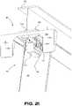
- FIG. 21is an isometric view of a portion of a strut attached to a trailer's floor beam in accordance with at least one embodiment of the invention.
- FIG. 22is a perspective view of a portion of a securing mechanism in accordance with at least one embodiment of the invention.
- FIG. 23is an isometric view of a strut attached to a trailer's floor beam in accordance with at least one embodiment of the invention.
- FIG. 24is a top plan view a strut attached to a trailer's floor beam in accordance with at least one embodiment of the invention.
- FIG. 25is an isometric view of a strut in accordance with at least one embodiment of the invention.
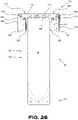
- FIG. 26is a front elevation view of a strut attached to a trailer's floor beam in accordance with at least one embodiment of the invention.
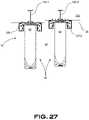
- FIG. 27is a back elevation view of a two struts attached to a trailer's floor beam having two different heights in accordance with at least one embodiment of the invention.
- FIG. 28is a back elevation view of a strut in accordance with at least one embodiment of the invention.
- FIG. 29is a side elevation view of a strut in accordance with at least one embodiment of the invention.
- FIG. 30is a top plan view of a strut in accordance with at least one embodiment of the invention.
- FIG. 31is a perspective view of a portion of a strut in accordance with at least one embodiment of the invention.
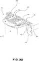
- FIG. 32is a perspective view of a portion of a strut in accordance with at least one embodiment of the invention.
- FIG. 33is a perspective view of a portion of a strut in accordance with at least one embodiment of the invention.
- FIG. 34is a perspective view of a portion of a strut in accordance with at least one embodiment of the invention.
- FIG. 35is a perspective view of a portion of a strut in accordance with at least one embodiment of the invention.
- FIG. 36is a perspective view of a portion of a strut in accordance with at least one embodiment of the invention.
- FIG. 37is a top plan section view of a portion of a strut in accordance with at least one embodiment of the invention.
- FIG. 38is a side elevation view of a strut in accordance with at least one embodiment of the invention.
- FIG. 39is a graph illustrating a load vs displacement of a strut in accordance with at least one embodiment of the invention.
- FIG. 40is a perspective view of a strut in accordance with at least one embodiment of the invention.
- FIG. 41is a perspective view of a strut in accordance with at least one embodiment of the invention.
- FIG. 1 , FIG. 2 and FIG. 3illustrate a road tractor 10 with a trailer 20 attached thereto equipped with a pair of skirt assemblies 30 , installed on each side of the trailer 20 along a longitudinal axis 34 , adapted to deflect and direct the airflow around the trailer 20 .
- Each aerodynamic skirt assembly 30includes a skirt panel 38 , adapted to be disposed on the side of the trailer 20 , and a plurality of securing mechanisms 42 adapted to secure the skirt panel 38 to the trailer 20 .
- the securing mechanisms 42are visible although not clearly illustrated in FIG. 1 , FIG. 2 and FIG. 3 and will be discussed in more details below.
- the skirt assembly 30helps channel the flow of air around the trailer 20 to reduce the air drag of the vehicle when the trailer 20 moves on the road, pulled by the road tractor 10 .
- the trailer 20includes slider rail 24 used to adjust the location of the set of wheels 50 on the trailer 20 , thus interacting with the length of the skirt panel 38 .
- the skirt assembly 30 of the present embodimentis mostly located under the trailer 20 , between the wheels 46 of the road tractor 10 and the wheels 50 of the trailer 20 .
- the skirt panels 38can alternatively extend forward up to the trailer supports 54 , also known as landing gears, and be secured thereto thus preventing complex skirt panel 38 arrangements through the securing mechanism 42 .
- the skirt panels 38are substantially vertically positioned on each side of the trailer 20 , preferably located as a vertical continuity of the trailer's side/wall, with a clearance with the ground by illustratively about 15-25 centimeters (about 6 to 12 inches).
- the air management around the trailer 20 provided by the skirt assembly 30reduces the air drag created by the trailer 20 by directing the flow of air around the trailer 20 .
- the flow of airwould otherwise turbulently move around and below the trailer 20 to create substantial air drag.
- the airflow management around the trailer 20 provided by the skirt assembly 30helps maintain laminar airflow around the trailer 20 that diminishes fuel consumption of the road tractor 10 .
- the skirt assembly 30also improves the safety of the vehicle by providing a barrier that can substantially restrict objects to get under the trailer 20 .
- the skirt panel 38is shaped with an optional progressive height 62 from a front portion 58 thereof.
- the skirt panels 38can alternatively also be installed at an angle, in respect to the vertical (not illustrated), on the trailer 20 to change the airflow pattern around the trailer 20 and more precisely adjust the aerodynamics to a specific vehicle shape.
- each skirt panel 38is installed directly on the side of the trailer 20 and, when seen from above, the front portion 58 that optionally progressively proximally leans angle 66 toward the center 34 of the trailer 20 .
- the recessed front portion 58 of the skirt panel 38improves the management of turbulent airflow generated by the road tractor 10 thus improving the aerodynamic efficiency of the skirt assembly 30 . Additional explanation about the shape of the skirt panel 38 will be provided in further details below.
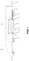
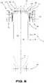
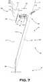
- FIG. 4 throughout FIG. 8are illustrating a securing mechanism 42 including a connector portion 80 and a strut portion 84 both centered along vertical axis 44 .
- the strut portion 84includes a strut member 90 , with a flex portion 104 thereof, securing the skirt panel 38 to a lower portion 94 thereof.
- a planar section 98includes holes 102 therein for securing the lower portion 94 of the skirt panel 38 with fasteners or rivets, for example.
- the strut portion 84includes a securing portion 106 to which is connected the strut portion 84 .
- the securing portion 106includes a stabilizer 110 , a trailer contacting portion 114 , a skirt panel contacting portion 118 and a pair of securing wings 120 .
- a stabilizer 110is located proximal to the longitudinal axis 34 of the trailer 20 when installed on a trailer 20 , proximally extending from a projection 70 of the strut member 90 to create a lever that help sustains the loads applied on the strut portion 84 by the skirt panel 38 .
- the skirt panel contacting portion 118includes a planar section 122 provided with a series of holes 126 therein for securing an upper portion 92 of the skirt panel 38 with fasteners or rivets, for example.
- Both planar section 98 , 122are preferably aligned along a unique vertical plane 74 for efficiently contacting the skirt panel 38 .
- the trailer contacting portion 114includes openings 130 therein to receive therein the connector portion 80 for securing the strut portion 84 to the trailer 20 .
- the connector portion 80is embodied as two opposed clamps 134 configured to be secured together with, for instance, two fasteners 138 .
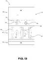
- the two opposed clamps 134are securing together the trailer contacting portion 114 of the strut portion 84 with a lower portion of an I-beam as illustrated in FIG. 13 throughout FIG. 18 .
- Each clamp 134uses an inclined member 160 and two contacting portions 162 , 166 for securing the connector portion 80 with the I-beam 142 .
- the connector portion 80is preferably made of two similar opposed clamps 134 to simplify the assembly and reduce the manufacturing cost.
- the clamps 134are made of a strong material capable of withstanding significant mechanical loads and can be shaped with a punch and die process. Metal, or the like, can be used. A material resistant to corrosion, or a protective layer, is also desirable given the condition of use of the connector portion 80 to prevent rust to undesirably attack the connector portion 80 .
- Each clamp 134is, in the present embodiment, made of bent sheet metal that is forming a collecting portion 146 , a securing portion 150 and a contacting portion 154 .
- the collecting portion 146includes a collecting member 158 embodied as an inclined member 160 positioned at an angle ⁇ , that is about between 30 degree and about 45 degree, and more preferably about 34 degree in the illustrated embodiment, to collect therein sections of I-beams 142 having different dimensions and thicknesses.
- the collecting member 158merges into a first contacting portion 162 , configured to laterally abut sides of an I-beam 142 , that merges into a second contacting portion 166 configured to vertically contact a surface of the connector portion 80 .
- a securing portion 170is formed between a first protruding member 174 and a second protruding member 178 .
- Both members 174 , 178are extending about a similar distance to allow leveled abutment of the two clamps 134 when secured and pulled toward each other with an intervening I-beam 142 having optimal dimensions.
- the second protruding member 178is also helpful to prevent premature rotation of the assembly when tightening the bolts 138 by its lever action and touching each other along a line to provide resistance to rotation to the assembly. Additional bents 182 are performed on the clamp 134 to increase the mechanical strength thereof.
- An elastic member 186embodied as an elastic band in the embodiment, is used to keep both clamps 134 together in clamping position prior to secure the clamps 134 to the I-beam 142 .
- Helical springs 188can optionally be used to pretense the assembly as illustrated in FIG. 10 .
- the pre-assembly of the two clamps 134are allowing suspending the pre-assembly of the two clamps 134 to the I-beam 1 to connect the parts of the aerodynamic skirt assembly 30 in place before securing them in a final operating configuration.
- Distance 190is preferably configured to be close to zero (0) when the two clamps are secured toward each other and two times distance 194 is preferably configured to be close to a thickness of a central member of the I-beam 142 when the clamps 134 are secured to a narrow I-beam 142 .
- distance 190 . 1 and 190 . 2is going to increase when the clamps 134 are secured to a wider I-beam.
- Holes 198are made in the securing portion 170 to accommodate bolts 138 therein to secure both clamps 134 together. The interaction of the securing mechanism 42 with an I-beam 142 is depicted in FIG. 15 throughout FIG. 16 .
- the collecting portion 146is compressing together vertically (y) and laterally (x) the trailer-contacting portion 114 and a lower portion 202 of the I-beam 142 .
- the illustrated structurealso has the capacity to adapt to a variety of I-beams 142 .
- the lower portion 202 (bottom flange) of the I-beamcan be wider 206 and/or thicker 210 and still be captured and secured by the connection portion 90 of the securing mechanism 42 .
- the lower portion 202 of the I-beam 142is illustratively varying from about 38 mm to about 80 mm width, and thickness of about 3 mm to about 13 mm. This is illustrated in FIG. 19 and in FIG. 20 .
- the strut portion 84is, for instance, sized and designed to buckle when a force F of about between 400 N to 600 N is applied along the longitudinal axis 308 .
- the buckling force Fcan alternatively be between about 450 N to 550 N.
- a narrower range of force Fcan alternatively be between about 470 N to 520 N without departing from the scope of the present invention.
- Corresponding force applied normal to the skirt panelcan be inferred from the axial buckling force above.
- the I-beam 142is parallel with the central axis 144 of the I-beam 142 in FIG. 15 throughout FIG. 21 and in FIG. 23 and FIG. 24 .
- the securing mechanism 42is constructed to keep the pair of clamps 134 aligned and allow misalignment of the strut portion 84 in respect with the I-beam 142 of the trailer 42 .
- the alignment between the clamps 134can be made by contacting the contacting portions 154 together.
- a spacer 220can be required to space apart the contacting portions 154 .
- the spacer 220better seen in FIG. 22 can be made of different material having suitable mechanical properties like steel, aluminum or plastic.
- the spacer 220includes optional voids 224 and ribs 228 to lighten the spacer 220 , reduce curing time, eliminate sink marks and reinforce desirable areas thereof.
- the spacerfurther includes fastener-receiving portions 228 configured to receive fasteners 138 therein.
- a misalignment between the strut portion 84 and the I-beam 142 of the trailer 42can occur if the trailer 20 has I-beams 142 that are not perfectly aligned and, depending of the installation configuration of the skirt panel 38 along the trailer 20 , the front portion 58 of the skirt panel 38 can proximally lean toward the center of the trailer 20 hence progressively curving or bending and be located at an angle with the I-beam 142 of the trailer 20 as illustrated in FIG. 23 and FIG. 24 .
- the size of the openings 130is designed to accommodate a flexible installation of the pair of clamps 134 that can be located to accommodate position variation with, for instance, an angle ⁇ thereof.
- the strut portion 84is preferably located on the trailer 20 to have the exterior of the skirt panel 38 vertically aligned, flush with the side wall of the trailer 20 .
- the skirt panel 38is hence used as a vertical continuity of the trailer's 20 side wall.
- Alignment guides 250are provided on the trailer-contacting portion 114 to assist the positioning and the installation of the strut portion 84 on the trailer 20 .
- the trailer-contacting portion 114incorporates alignment guides 250 , embodied as protruding members, located at predetermined locations on the trailer-contacting portion 114 from the skirt panel contacting portion 118 used as reference plane for laterally locating the skirt panel 38 .
- the alignment guides 250can be seen throughout the Figures using some different configurations of distance and shape.
- the alignment guides 250can alternatively be embodies as extrusions molded in the strut portion 84 , one or many series of holes for receiving added pins, metallic or not, removable stems, clips or the like without departing from the scope of the present description.
- One way to facilitate the installation of the securing mechanism 42is to assemble the connection portion 80 to the strut portion 84 prior to assemble the connection portion 80 with the I-beam 142 . Then the securing mechanism 42 can be transversally located along the I-beam 142 and the alignment guides 250 are contacting the interior side of the trailer 20 contour frame 254 .
- the predetermined distance 258 between the alignment guides 250 and the skirt-contacting portion 118in consideration of the thickness of the contour frame 254 .
- the thickness of the contour frame 254equals the thickness of skirt panel 38 and the alignment guides 250 will be aligned with the skirt-contacting portion 118 as illustrated in FIG. 29 .
- the thickness of the contour frame 254is larger than the thickness of skirt panel 38 and the alignment guides 250 will be protrude beyond the skirt-contacting portion 118 as illustrated in FIG. 34 .
- the thickness of the contour frame 254is smaller than the thickness of skirt panel 38 and the alignment guides 250 will be aligned with the skirt-contacting portion 118 .
- the predetermined distance 258is generally between about 7 mm and about 12 mm.
- the alignment guides 250have, for instance, a height of between about 6 mm to about 25 mm.
- a plurality of sets of holes 126are provided with a distance 262 variation to accommodate different height of I-beams 142 .
- the I-beam 142 heightcan be different depending of the trailer 20 .
- Tall I-beams 142 . 1can be used to increase the strength of the trailer 20 to maximize the cargo load.
- the portion of the trailer 20 accommodating the slider rail 24can require shorter I-beam 142 . 2 to clear the contour frame 254 of the trailer 20 .
- the higher set of holes 126 . 1is going to be used in cooperation with a high I-beam 142 . 1 while the lower set of holes 126 . 2 is going to be used in cooperation with a low I-beam 142 . 2 as depicted in FIG. 26 .
- the stabilizer 110that can be seen in many Figures is an extension of the trailer-contacting portion 114 to extend the contact surface with the I-beam 142 to improve the strength of the upper portion 92 of the strut portion 84 .
- the transversal force 266 , and-or the axial force 268 , applied to the skirt panel 38is transmitted to as a moment 270 , a normal reaction 274 and/or an axial reaction 278 to the upper portion 92 of the strut portion 84 .
- the stabilizer 110function as a transfer lever element of the loads acting on the strut member 90 into the I-beam 142 on which the strut portion 84 is installed.
- the stress transferred towards the openings 130 locations due to deformation and flexing of the strut portion 84is reduced by the stabilizer 110 .
- the radius 282 of sweep of the stabilizer 110illustrated in FIG. 30 and FIG. 31 , is following a generally constant radius as the radius of the strut member 90 to optimize its compatibility with the strut member 90 .
- the geometry of the strut member 90is going to be discussed in further details below.
- the trailer-contacting portion 114includes a plurality of reinforcement ribs 290 oriented in different directions, generally orthogonal to each other, to help minimize deformation of the strut portion 84 .
- the deformation in the Y directionis generally due to moment created by the weight of the skirt panel 38 and the stress applied to the strut portion 84 when contacting a foreign object.
- Ribs 290 in the X directionstrengthen the skirt-contacting portion 118 from sagging due to the weight of the skirt panel 38 and the stress applied to the strut portion 84 when contacting a foreign object.
- the ribs 290are preferably extending only from one surface, the upper surface or the lower surface, to facilitate the manufacturing process of the part. However, the surface of the stabilizer 110 that is in contact with the I-beam 142 has no ribs 290 to optimize its capacity to sustain significant pressure by spreading it over a larger contact surface and to avoid ribs 290 plastic deformation.
- the strut portion 84is sized and designed to allow connector portion 80 access through an access portion 300 to access the fasteners 138 during installation of the securing mechanism 42 .
- the angle ⁇between the plane 304 where the skirt panel 38 is going to be secured to the strut portion 84 and the axis 308 of the strut member 90 .
- the angle ⁇is between about 10 degree and about 30 degree.
- the angle ⁇is preferably between about 12 degree and about 18 degree. Most preferably, the angle ⁇ is between about 15 degree and about 16 degree depending on the type of use and the type of trailer 20 .
- the shape of the strut member 90that includes a concave portion 320 (when seen from a side of the trailer 20 toward the trailer 20 ).
- the concave portion 320 of the strut portion 90offers some advantages in the manner the strength of the strut portion 90 is applied to the skirt assembly 30 when an external force, that might be caused by contacting an external object, is applied to the strut portion 84 .
- the side of the cavity of the concave portion 320has an impact on the amount of force required to buckle and bend the strut member 90 .
- the cavity of the concave portion 320 toward the skirt panel 38provides more strength when a force is applied toward the trailer 20 .
- the concave portion 320could alternatively be inverted toward the center of the trailer without departing from the scope of the present description.
- a stronger force directed toward the traileris required to bend the member 90 than if the cavity of the concave portion 320 is in the opposite direction toward the center of the trailer 20 .
- the concave portion 320is going to change progressively as illustrated in FIG. 37 and the section of the concave portion 320 tends to straighten 346 , as illustrated by arrows 324 .
- the resistance of the strut member 90will be strong until the strut member 90 buckles 330 and flexes more easily after it has buckled as illustrated in FIG. 39 .
- Thisoffers significant advantages by maintaining strongly the skirt panel 38 in an aerodynamically operating configuration 334 that could flex and provide some deflection 338 until a predetermined load is applied that overcome the buckling load threshold 330 of the strut member 90 design.
- the strut member 90is going to be strong and maintain an efficient operating configuration despite the loads applied thereon when the loads are smaller than the buckling load threshold 330 and will become less resistant when buckling and more prone to flex and deflect significantly 342 when the load applied thereon is beyond the buckling load threshold 330 .
- the strut portion 84can be built from a variety of polymers that are flexible and resilient enough to perform the required flex.
- Materialssuch as, but not limited to, polypropylene, nylon, nylon co-polymer, thermoplastic poly olefin, polyethylene, polycarbonate and thermosets, charged with fibers or not, could be used.
- other materialsuch as metal that are designed to remain in their elastic domain can also be suitable to bend, buckle and automatically recover its original shape.
- Manufacturing processesincluding, but not limited to, injection molding, machining, thermoforming and RTM could be used in consideration of the selected material and other constraints.
- the strut member 90includes two concave portions 320 . 1 , 320 . 2 directed toward opposite directions.
- a transition portion 350 where the two concave portions 320 . 1 , 320 . 2 are mergingis illustratively located around the middle portion of the strut member 90 .
- the transition portion 350delimits a portion of the strut member 90 where the flex behavior of the strut member 90 is not within the desired load-supporting range of either of the two concave portions 320 . 1 , 320 . 2 .
- the transition portion 350includes the portion of the strut member 90 that is not concave and offers much less resistance to buckling and bending.
- the size of the transition portion 350can vary depending of the particular design of the strut member 90 .
- An advantage of the embodiment illustrated in FIG. 40 and FIG. 41would be to provide a comparable resistance when the skirt panel 38 sustains a force in the direction of the trailer 20 and a force in the direction opposed to the trailer 20 , taking advantages of the location and the direction of the cavities 320 . 1 , 320 . 2 to allow resiliency behaviors in both directions.
- FIG. 40illustrates a rather flat transition portion 350 while FIG. 41 illustrates an alternate design including a transition portion with an offset portion 354 to ensure one edge of each of the two concave portions 320 . 1 , 320 . 2 are co-linear to help standardizing the behavior of both sides of the strut member 90 .
- the transition portion 350can alternatively include reinforcing ribs to prevent bending. Ribs (not illustrated) can be added on each edges of the strut member 90 over the length of the transition portion 350 . Additional ribs can be localized over the surface of the transition portion 350 . Alternatively, a pair of clamp members (not illustrated) can be added to sandwich the transition portion 350 and secured together with fasteners, for example. The pair of clamp members prevents bending in the region of the strut member 90 that is covered by the pair of clamp members. The design, shape, length and location of the pair of clamp members can be used to modify, adjust and optimize the behavior of the strut portion 84 .
Landscapes
- Engineering & Computer Science (AREA)
- Chemical & Material Sciences (AREA)
- Combustion & Propulsion (AREA)
- Transportation (AREA)
- Mechanical Engineering (AREA)
- Physics & Mathematics (AREA)
- Fluid Mechanics (AREA)
- Body Structure For Vehicles (AREA)
Abstract
Description
| TABLE A | ||||
| Strut member's | Minimum | Maximum | ||
| Depth A | 5 mm | 25 mm | ||
| Depth B | 6 | 20 mm | ||
| Depth C | 7 | 15 mm | ||
| Depth D | 8 mm | 12 | ||
| Width A | ||||
| 50 mm | 180 mm | |||
| Width B | 60 | 160 | ||
| Width C | ||||
| 70 mm | 140 | |||
| Width D | ||||
| 80 | 120 | |||
| Thickness A | ||||
| 2 | 10 | |||
| Thickness B | ||||
| 3 mm | 8 mm | |||
| Thickness C | 4 mm | 7 mm | ||
| Thickness D | 4.5 mm | 6 mm | ||
Claims (20)
Priority Applications (4)
| Application Number | Priority Date | Filing Date | Title |
|---|---|---|---|
| US16/832,678US11420690B2 (en) | 2015-09-07 | 2020-03-27 | Aerodynamic skirt securing connector with angular assembly capability |
| US17/892,928US11780510B2 (en) | 2015-09-07 | 2022-08-22 | Aerodynamic skirt securing connector comprising a stabilizer |
| US18/377,771US12162539B2 (en) | 2015-09-07 | 2023-10-07 | Aerodynamic skirt securing connector comprising a stabilizer |
| US18/973,345US20250100631A1 (en) | 2015-09-07 | 2024-12-09 | Structure and method for securing a skirt panel to a vehicle |
Applications Claiming Priority (5)
| Application Number | Priority Date | Filing Date | Title |
|---|---|---|---|
| US201562215129P | 2015-09-07 | 2015-09-07 | |
| US201662314082P | 2016-03-28 | 2016-03-28 | |
| US15/257,571US10414448B2 (en) | 2015-09-07 | 2016-09-06 | Support system for aerodynamic skirt assembly and method of installation thereof |
| US16/531,317US10640156B2 (en) | 2015-09-07 | 2019-08-05 | Strut portion with buckling capability for aerodynamic skirt |
| US16/832,678US11420690B2 (en) | 2015-09-07 | 2020-03-27 | Aerodynamic skirt securing connector with angular assembly capability |
Related Parent Applications (1)
| Application Number | Title | Priority Date | Filing Date |
|---|---|---|---|
| US16/531,317ContinuationUS10640156B2 (en) | 2015-09-07 | 2019-08-05 | Strut portion with buckling capability for aerodynamic skirt |
Related Child Applications (1)
| Application Number | Title | Priority Date | Filing Date |
|---|---|---|---|
| US17/892,928ContinuationUS11780510B2 (en) | 2015-09-07 | 2022-08-22 | Aerodynamic skirt securing connector comprising a stabilizer |
Publications (2)
| Publication Number | Publication Date |
|---|---|
| US20200223497A1 US20200223497A1 (en) | 2020-07-16 |
| US11420690B2true US11420690B2 (en) | 2022-08-23 |
Family
ID=58189935
Family Applications (6)
| Application Number | Title | Priority Date | Filing Date |
|---|---|---|---|
| US15/257,571Active2037-05-05US10414448B2 (en) | 2015-09-07 | 2016-09-06 | Support system for aerodynamic skirt assembly and method of installation thereof |
| US16/531,317ActiveUS10640156B2 (en) | 2015-09-07 | 2019-08-05 | Strut portion with buckling capability for aerodynamic skirt |
| US16/832,678ActiveUS11420690B2 (en) | 2015-09-07 | 2020-03-27 | Aerodynamic skirt securing connector with angular assembly capability |
| US17/892,928ActiveUS11780510B2 (en) | 2015-09-07 | 2022-08-22 | Aerodynamic skirt securing connector comprising a stabilizer |
| US18/377,771ActiveUS12162539B2 (en) | 2015-09-07 | 2023-10-07 | Aerodynamic skirt securing connector comprising a stabilizer |
| US18/973,345PendingUS20250100631A1 (en) | 2015-09-07 | 2024-12-09 | Structure and method for securing a skirt panel to a vehicle |
Family Applications Before (2)
| Application Number | Title | Priority Date | Filing Date |
|---|---|---|---|
| US15/257,571Active2037-05-05US10414448B2 (en) | 2015-09-07 | 2016-09-06 | Support system for aerodynamic skirt assembly and method of installation thereof |
| US16/531,317ActiveUS10640156B2 (en) | 2015-09-07 | 2019-08-05 | Strut portion with buckling capability for aerodynamic skirt |
Family Applications After (3)
| Application Number | Title | Priority Date | Filing Date |
|---|---|---|---|
| US17/892,928ActiveUS11780510B2 (en) | 2015-09-07 | 2022-08-22 | Aerodynamic skirt securing connector comprising a stabilizer |
| US18/377,771ActiveUS12162539B2 (en) | 2015-09-07 | 2023-10-07 | Aerodynamic skirt securing connector comprising a stabilizer |
| US18/973,345PendingUS20250100631A1 (en) | 2015-09-07 | 2024-12-09 | Structure and method for securing a skirt panel to a vehicle |
Country Status (3)
| Country | Link |
|---|---|
| US (6) | US10414448B2 (en) |
| CN (1) | CN106627805A (en) |
| CA (2) | CA2940932C (en) |
Families Citing this family (18)
| Publication number | Priority date | Publication date | Assignee | Title |
|---|---|---|---|---|
| CA2762860C (en)* | 2011-02-18 | 2019-03-12 | Laydon Composites Ltd. | Clamp assembly for mounting panels to i-beams |
| US10414448B2 (en)* | 2015-09-07 | 2019-09-17 | Transtex Llc | Support system for aerodynamic skirt assembly and method of installation thereof |
| US10343731B2 (en)* | 2016-09-30 | 2019-07-09 | Wabash National, L.P. | Skirt system mount bracket assembly |
| US10220888B2 (en) | 2016-10-19 | 2019-03-05 | Laydon Composites Ltd. | Angled clamp assembly for mounting panels to I-beams |
| WO2018097815A1 (en)* | 2016-11-22 | 2018-05-31 | Compagnie Generale Des Etablissements Michelin | Aerodynamic trailer system with dual stiffness skirt |
| EP3577015B1 (en)* | 2017-02-03 | 2021-04-14 | Compagnie Générale des Etablissements Michelin | Aerodynamic system with dual zone fairing for truck |
| CA2996392A1 (en)* | 2017-02-24 | 2018-08-24 | Jiadebao Inc. | Aerodynamic skirt device for trailer |
| MX2020004197A (en)* | 2017-10-25 | 2020-08-13 | Michelin & Cie | Resilient gap reducing support structures and methods. |
| CN109606485B (en)* | 2019-01-23 | 2023-05-05 | 吉林大学 | An electronically controlled adjustable tail system and control method for a formula racing car |
| WO2020160340A1 (en)* | 2019-01-30 | 2020-08-06 | Transtex Llc | Multi-panel skirt system for cargo enclosures |
| US11451034B2 (en) | 2019-05-30 | 2022-09-20 | The Boeing Company | Raceway systems and methods for routing transferring components within an interior cabin of an aircraft |
| US10971907B2 (en)* | 2019-05-30 | 2021-04-06 | The Boeing Company | Transferring component routing systems and methods within an interior cabin of an aircraft |
| US11738704B2 (en) | 2020-04-02 | 2023-08-29 | Great Dane Llc | Underride guard assembly for trailers |
| US11713013B2 (en) | 2020-07-09 | 2023-08-01 | Fontaine Commercial Trailer, Inc. | Side underride guard assembly for a trailer |
| US20250196946A1 (en)* | 2022-03-03 | 2025-06-19 | Trailer Aerodynamics Llc | Aerodynamic system for trailer with sliding connection |
| US20250171092A1 (en)* | 2022-03-03 | 2025-05-29 | Trailer Aerodynamics Llc | Aerodynamic system for trailer with non-parallel bending member |
| MX2024010660A (en)* | 2022-03-03 | 2024-09-10 | Michelin & Cie | Aerodynamic system for trailer with compression connection. |
| US12145659B2 (en)* | 2022-04-29 | 2024-11-19 | Zf Cv Systems Europe Bv | Trailer fairing bracket |
Citations (112)
| Publication number | Priority date | Publication date | Assignee | Title |
|---|---|---|---|---|
| US1127241A (en) | 1913-10-22 | 1915-02-02 | Charles Barnard Burdon | Safety device for motor-vehicles. |
| US1511085A (en) | 1924-06-19 | 1924-10-07 | Mcintyre Robert | Safety guard for the rear wheels of vehicles |
| US1846269A (en) | 1927-07-02 | 1932-02-23 | Goodyear Tire & Rubber | Method of making tires |
| US2318863A (en) | 1940-12-20 | 1943-05-11 | Jabelmann Otto | Railway car |
| US2546268A (en) | 1947-10-16 | 1951-03-27 | Louis Legris | Adjustable seat for farm implements |
| US2605119A (en) | 1949-11-19 | 1952-07-29 | Maxwell L Earnest | Splash guard for vehicles |
| US3415566A (en) | 1967-01-16 | 1968-12-10 | William H. Kerrigan | Streamlining apparatus for cargo carrying vehicles |
| US3697120A (en) | 1969-11-03 | 1972-10-10 | Walter Selden Saunders | Drag reducer for land vehicles |
| US3711146A (en) | 1970-07-29 | 1973-01-16 | White Motor Corp | Streamlined vehicle configuration |
| US3775917A (en) | 1972-07-15 | 1973-12-04 | Silver Top Mfg Co Inc | Suspended skirting for below dwelling, |
| US3854769A (en) | 1969-11-03 | 1974-12-17 | W Saunders | Drag reducer for land vehicles |
| BE845298A (en) | 1975-08-21 | 1976-12-16 | TRUCK INCLUDING REDUCED AIR RESISTANCE | |
| US4119339A (en) | 1976-09-10 | 1978-10-10 | Arthur Sherman Heimburger | Vehicle undercarriage air deflector |
| US4262953A (en) | 1979-07-19 | 1981-04-21 | Premix, Inc. | Undermounted air deflector for trucks and trailers |
| US4318566A (en) | 1980-04-04 | 1982-03-09 | Takena Industries, Inc. | Wind fairing device |
| US4386801A (en) | 1979-11-28 | 1983-06-07 | Team Lotus International Limited | Ground effect vehicle |
| US4397496A (en) | 1980-11-03 | 1983-08-09 | Drygas Iii Thomas C J | Vehicular and passenger transportation system |
| US4418853A (en) | 1982-08-30 | 1983-12-06 | Goodway Transport, Inc. | Pallet carrier |
| US4421354A (en) | 1982-01-07 | 1983-12-20 | Sepco Enterprises, Inc. | Air foil construction |
| US4486046A (en) | 1982-09-29 | 1984-12-04 | Whitney Michael L | Undercarriage airstream deflector assembly for truck trailers and the like |
| JPS6012378A (en) | 1983-06-30 | 1985-01-22 | Nissan Motor Co Ltd | Front undercover structure |
| US4511170A (en) | 1982-07-23 | 1985-04-16 | Sankrithi Mithra M K V | Aerodynamic device for land vehicles |
| US4585262A (en) | 1985-03-07 | 1986-04-29 | General Motors Corporation | Air dam for motor vehicle |
| US4611847A (en) | 1985-10-18 | 1986-09-16 | Navistar International Corporation | Inflatable and extendable vehicle skirt |
| US4616869A (en) | 1982-12-17 | 1986-10-14 | Daimler-Benz Aktiengesellschaft | Aerodynamic fairing for passenger cars and utility-type motor vehicles |
| US4640541A (en) | 1985-09-17 | 1987-02-03 | Fitzgerald Corporation | Under-trailer air deflector |
| US4746160A (en) | 1986-06-30 | 1988-05-24 | Wiesemeyer Robert L | Streamlined truck with semitrailer |
| US5078448A (en) | 1989-05-19 | 1992-01-07 | Navistar International Transportation Corp. | Cab to trailer air deflector |
| US5094503A (en) | 1989-02-07 | 1992-03-10 | Dare Bryan Valerian J | Vehicle aerodynamics |
| US5190342A (en) | 1991-09-24 | 1993-03-02 | Paccar Inc. | Tractor-trailer aerodynamic drag reduction apparatus and method |
| US5280990A (en) | 1991-10-08 | 1994-01-25 | Rinard Gordon L | Vehicle drag reduction system |
| US5332280A (en) | 1992-10-09 | 1994-07-26 | Dupont J | Demountable deflector for shipping containers and the like |
| US5358210A (en) | 1992-03-31 | 1994-10-25 | Hutchinson | Device for filtering vibration, and a fixing system comprising a plurality of such devices for fixing a load on a support |
| US5465669A (en) | 1994-11-29 | 1995-11-14 | Andrus; Paul G. L. | Intermodal rail drag reducer with flexible enclosure between CWS |
| US5487586A (en) | 1994-01-11 | 1996-01-30 | Wells Cargo, Inc. | Frame for securing a wind deflector to a trailer |
| US5536062A (en) | 1994-12-08 | 1996-07-16 | Spears; Dan E. | Cross wind conditioning for a tractor trailer combination |
| US5609384A (en) | 1996-06-20 | 1997-03-11 | Loewen; Gordon | Fairing |
| US5788321A (en) | 1996-05-22 | 1998-08-04 | Freightliner Corporation | Removable side fairing for a vehicle |
| US6017013A (en) | 1997-09-12 | 2000-01-25 | Trw Inc. | Damped instrument kinematic mounts |
| JP2002019574A (en) | 2000-07-07 | 2002-01-23 | Isuzu Motors Ltd | Structure and method for mounting side skirt of motor truck |
| US20020021023A1 (en) | 2000-06-20 | 2002-02-21 | Leban Michael F. | Hybrid air boost vehicle and method for making same |
| US6428084B1 (en) | 2001-04-24 | 2002-08-06 | Richard M. Liss | Fuel-efficient tractor-trailer system |
| US20030057736A1 (en) | 2001-08-24 | 2003-03-27 | Windyne Inc. | Adjustable trailer underbody fairing |
| US20030234555A1 (en) | 2002-06-24 | 2003-12-25 | Hojna Joseph J. | Air deflector for attachment to a lower surface of a vehicle and method for producing same |
| US6685256B1 (en) | 2002-12-23 | 2004-02-03 | Carl L. Shermer | Trailer drag reduction system |
| US20040155485A1 (en) | 2000-12-20 | 2004-08-12 | Rudyard Hamnett | Deflector for the air-flow in a motor-vehicle |
| US20050040668A1 (en) | 2003-08-21 | 2005-02-24 | Wood Richard M. | Cross flow vortex trap device and method for reducing the aerodynamic drag of ground vehicles |
| US20050056117A1 (en) | 2003-07-22 | 2005-03-17 | Kaiser Compositek, Inc. | Composite strut and method of making same |
| US20050146161A1 (en) | 2004-01-05 | 2005-07-07 | Uland William B. | Under-vehicle aerodynamic efficiency improvement device |
| US20050161976A1 (en) | 2003-05-30 | 2005-07-28 | The Regents Of The University Of California | Aerodynamic drag reduction apparatus for wheeled vehicles in ground effect |
| US6932419B1 (en) | 2005-02-03 | 2005-08-23 | Mccullough William | Aerodynamic guiding arrangements for vehicles |
| US7040682B2 (en) | 2003-10-15 | 2006-05-09 | Honda Motor Co., Ltd. | Installation structure for a side sill garnish |
| US20060103167A1 (en) | 2004-11-12 | 2006-05-18 | Wong Alec C | Systems and methods for reducing the aerodynamic drag on vehicles |
| US7055890B1 (en) | 2003-06-30 | 2006-06-06 | Alfa Leisure, Inc. | Awning for recreational vehicles |
| US7073845B2 (en) | 2003-05-30 | 2006-07-11 | The Regents Of The University Of California | Aerodynamic drag reduction apparatus for gap-divided bluff bodies such as tractor-trailers |
| US20060152038A1 (en) | 2004-10-04 | 2006-07-13 | Freight Wing Inc. | Device for reducing vehicle aerodynamic resistance |
| US7104591B1 (en) | 2005-10-03 | 2006-09-12 | Sanns Randy A | Windbreaker air drag reduction system |
| US20060273625A1 (en) | 2005-05-13 | 2006-12-07 | Andrus Paul G | Automatic rear airfoil for vehicle |
| US7163258B2 (en) | 2003-10-24 | 2007-01-16 | International Truck Intellectual Property Company, Llc | Sliding chassis skirt |
| WO2007007342A2 (en) | 2005-07-14 | 2007-01-18 | Doron Neuburger | Drag reducing system |
| US7168757B2 (en) | 2004-09-28 | 2007-01-30 | Honda Motor Co., Ltd. | Side sill garnish having sound absorbing member which includes outer peripheral rigid portions |
| US20070120397A1 (en) | 2005-11-29 | 2007-05-31 | Layfield Brian P | Trailer skirt panel |
| US20070132278A1 (en) | 2005-12-12 | 2007-06-14 | Paul Lester | Vehicle panels and their method of construction |
| US20070176466A1 (en) | 2006-02-02 | 2007-08-02 | Dolan Robert A | Flexible truck skirt with floating mount |
| US20070257512A1 (en) | 2006-05-08 | 2007-11-08 | Scott Anderson | Fuel efficient dynamic air dam system |
| US20080061597A1 (en) | 2006-09-13 | 2008-03-13 | Aerofficient, Llc. | Vehicle fairing structure |
| US20080061598A1 (en) | 2006-09-13 | 2008-03-13 | Aerofficient, Llc. | Vehicle fairing system |
| US20080093887A1 (en) | 2006-06-19 | 2008-04-24 | Solus Solutions And Technologies, Llc. | Mini skirt aerodynamic fairing device for reducing the aerodynamic drag of ground vehicles |
| US20080179916A1 (en) | 2007-01-25 | 2008-07-31 | Breakfield Kenneth R | Reduced wind resistant haulage vehicle apparatus |
| US20080217957A1 (en) | 2007-03-05 | 2008-09-11 | International Truck Intellectual Property Company, Llc | Aerodynamic forebody shape for van trailer |
| US20080238139A1 (en) | 2007-03-30 | 2008-10-02 | Francis Cardolle | Fairing for a trailer |
| US20080303311A1 (en) | 2007-06-08 | 2008-12-11 | Vanguard National Trailer Corporation | Crash attenuating underride guard |
| US20080303309A1 (en) | 2005-04-21 | 2008-12-11 | Roderick Dayton | Vehicle Air Dam System |
| US20090146453A1 (en) | 2007-10-23 | 2009-06-11 | Ortega Jason M | Vehicle Underbody Fairing |
| US20090160214A1 (en) | 2004-09-18 | 2009-06-25 | Jost-Werke Gmbh | Adjusting device, air deflecting system, control member and device enabling aerodynamic resistance of a semi-trailer to be reduced |
| US20090189414A1 (en) | 2008-01-29 | 2009-07-30 | Mathieu Boivin | Aerodynamic trailer skirts |
| US20090195017A1 (en) | 2006-06-19 | 2009-08-06 | Richard Wood | Mini skirt aerodynamic fairing device for reducing the aerodynamic drag of ground vehicles |
| US20090212596A1 (en) | 2008-02-21 | 2009-08-27 | Aerofficient Llc | Vehicle side fairing system |
| US20090212595A1 (en) | 2008-02-21 | 2009-08-27 | Aeroefficient Llc | Vehicle side fairing system |
| US20090230726A1 (en) | 2007-03-09 | 2009-09-17 | Aeroficcient Llc | Vehicle fairing structure |
| US7665795B2 (en) | 2005-07-26 | 2010-02-23 | Honda Access Corporation | Side-under spoiler |
| US20100117396A1 (en) | 2008-11-12 | 2010-05-13 | Dayton Roderick M | System for reducing aerodynamic drag on vehicles |
| US7789453B2 (en) | 2007-05-30 | 2010-09-07 | Vanguard National Trailer Corporation | Trailer keel |
| US20100231000A1 (en) | 2009-03-13 | 2010-09-16 | Paul Guy Andrus | Inflatable trailer skirt |
| US20100264690A1 (en)* | 2009-04-16 | 2010-10-21 | James Bruce Brown | Side skirt system for a trailer |
| WO2011019766A2 (en) | 2009-08-11 | 2011-02-17 | Draggone Aerodynamics, Inc. | Device for improving a tractor-trailer combination truck aerodynamics in the gap between the tractor and trailer |
| US20110204677A1 (en) | 2009-08-21 | 2011-08-25 | Wood Richard M | Dam skirt aerodynamic fairing device |
| CA2693953A1 (en) | 2010-03-18 | 2011-09-18 | Gilles Nadon | Method of laying up an aerodynamic skirt with interchangeable parts without requiring tools |
| US20110233960A1 (en) | 2010-03-24 | 2011-09-29 | Richard Heinz | Aerodynamic skirts for truck trailers |
| US20110241377A1 (en) | 2010-04-02 | 2011-10-06 | Daimler Trucks North America Llc | Dynamically adjustable aerodynamic vehicle devices |
| US20110285167A1 (en) | 2010-05-24 | 2011-11-24 | Joshua Butler | Aerodynamic and protective vehicle panel assembly and method of constructing same |
| US20120032475A1 (en) | 2010-08-03 | 2012-02-09 | Ridge Corporation | Aerodynamic skirt assembly |
| US20120074728A1 (en) | 2010-05-27 | 2012-03-29 | Strehl, Llc | Aerodynamic Trucking Systems |
| US20120091754A1 (en) | 2010-10-13 | 2012-04-19 | Sang Sig Lee | Vehicle air deflection system |
| US8186745B2 (en) | 2009-09-15 | 2012-05-29 | Freight Wing Inc. | Device for reducing vehicle aerodynamic resistance |
| US8191956B1 (en) | 2010-04-09 | 2012-06-05 | Utility Trailer Manufacturing Company | Vehicle with aerodynamic system |
| US8413937B2 (en) | 2010-04-14 | 2013-04-09 | Innovative Trailer Design Technologies, Inc. | Side skirt mounting assembly for container chassis |
| US8517452B2 (en) | 2010-12-07 | 2013-08-27 | Timothy Kenevan | Tractor-trailer cross wind blocker |
| US8550540B1 (en) | 2012-09-05 | 2013-10-08 | Thomas W. Pacholyk | Aerodynamic device for trailers and the like |
| US20140019010A1 (en) | 2012-07-11 | 2014-01-16 | Advanced Transit Dynamics, Inc. | Retractable aerodynamic structures for cargo bodies and methods of controlling positioning of the same |
| US20140300134A1 (en) | 2013-04-04 | 2014-10-09 | Fleet Engineers, Inc. | Trailer side skirt assembly |
| US8899660B1 (en) | 2013-02-19 | 2014-12-02 | Eleanor Praskovskaya | Aerodynamic skirts for land vehicles |
| US20140353443A1 (en) | 2013-05-29 | 2014-12-04 | Sheng-Chien KUO | Load Bearing Structure for a Large-scale Vehicle |
| US20150259014A1 (en) | 2014-03-11 | 2015-09-17 | Wabash National, L.P. | Side skirt system for a trailer |
| US9139241B1 (en) | 2014-10-17 | 2015-09-22 | Paccar Inc | Vehicle drag reduction device |
| US9199675B2 (en) | 2013-12-12 | 2015-12-01 | Megan Elizabeth Miller | Corner coupled vortex structures, trailers, and vehicles including the same |
| US20160096558A1 (en) | 2014-10-01 | 2016-04-07 | Transtex Composite Inc. | Modular aerodynamic skirt assembly |
| US20170066487A1 (en) | 2015-09-07 | 2017-03-09 | Transtex Composite Inc. | Support system for aerodynamic skirt assembly and method of installation thereof |
| US9919750B2 (en)* | 2013-08-15 | 2018-03-20 | Wabash National, L.P. | Side skirt system for reducing drag |
| WO2018097815A1 (en) | 2016-11-22 | 2018-05-31 | Compagnie Generale Des Etablissements Michelin | Aerodynamic trailer system with dual stiffness skirt |
| US20180244228A1 (en) | 2017-02-24 | 2018-08-30 | Jiadebao Inc. | Aerodynamic skirt device for trailer |
| US20190152541A1 (en) | 2016-10-19 | 2019-05-23 | Laydon Composites Ltd. | Angled clamp assembly for mounting panels to i-beams |
Family Cites Families (5)
| Publication number | Priority date | Publication date | Assignee | Title |
|---|---|---|---|---|
| CA2528558C (en)* | 2005-11-29 | 2013-04-09 | Brian Peter Layfield | Trailer skirt panel |
| CN201457386U (en)* | 2009-08-06 | 2010-05-12 | 上海磁浮交通发展有限公司 | Maglev track inspection vehicle compartment skirt |
| US8727425B1 (en)* | 2010-05-27 | 2014-05-20 | Strehl, Llc | Aerodynamic trucking systems |
| CN203920944U (en)* | 2013-12-06 | 2014-11-05 | 晟通科技集团有限公司 | Railway carriage or compartment car |
| CN203637832U (en)* | 2014-01-14 | 2014-06-11 | 南京兴宇铁路工艺装备制造有限公司 | Skirt board structure of passenger train |
- 2016
- 2016-09-06USUS15/257,571patent/US10414448B2/enactiveActive
- 2016-09-06CACA2940932Apatent/CA2940932C/enactiveActive
- 2016-09-06CACA3147914Apatent/CA3147914A1/enactivePending
- 2016-09-07CNCN201610807676.0Apatent/CN106627805A/enactivePending
- 2019
- 2019-08-05USUS16/531,317patent/US10640156B2/enactiveActive
- 2020
- 2020-03-27USUS16/832,678patent/US11420690B2/enactiveActive
- 2022
- 2022-08-22USUS17/892,928patent/US11780510B2/enactiveActive
- 2023
- 2023-10-07USUS18/377,771patent/US12162539B2/enactiveActive
- 2024
- 2024-12-09USUS18/973,345patent/US20250100631A1/enactivePending
Patent Citations (136)
| Publication number | Priority date | Publication date | Assignee | Title |
|---|---|---|---|---|
| US1127241A (en) | 1913-10-22 | 1915-02-02 | Charles Barnard Burdon | Safety device for motor-vehicles. |
| US1511085A (en) | 1924-06-19 | 1924-10-07 | Mcintyre Robert | Safety guard for the rear wheels of vehicles |
| US1846269A (en) | 1927-07-02 | 1932-02-23 | Goodyear Tire & Rubber | Method of making tires |
| US2318863A (en) | 1940-12-20 | 1943-05-11 | Jabelmann Otto | Railway car |
| US2546268A (en) | 1947-10-16 | 1951-03-27 | Louis Legris | Adjustable seat for farm implements |
| US2605119A (en) | 1949-11-19 | 1952-07-29 | Maxwell L Earnest | Splash guard for vehicles |
| US3415566A (en) | 1967-01-16 | 1968-12-10 | William H. Kerrigan | Streamlining apparatus for cargo carrying vehicles |
| US3697120A (en) | 1969-11-03 | 1972-10-10 | Walter Selden Saunders | Drag reducer for land vehicles |
| US3854769A (en) | 1969-11-03 | 1974-12-17 | W Saunders | Drag reducer for land vehicles |
| US3711146A (en) | 1970-07-29 | 1973-01-16 | White Motor Corp | Streamlined vehicle configuration |
| US3775917A (en) | 1972-07-15 | 1973-12-04 | Silver Top Mfg Co Inc | Suspended skirting for below dwelling, |
| BE845298A (en) | 1975-08-21 | 1976-12-16 | TRUCK INCLUDING REDUCED AIR RESISTANCE | |
| DE2537217A1 (en) | 1975-08-21 | 1977-03-03 | Maschf Augsburg Nuernberg Ag | TRUCK WITH REDUCED AIR RESISTANCE |
| US4119339A (en) | 1976-09-10 | 1978-10-10 | Arthur Sherman Heimburger | Vehicle undercarriage air deflector |
| US4262953A (en) | 1979-07-19 | 1981-04-21 | Premix, Inc. | Undermounted air deflector for trucks and trailers |
| US4386801A (en) | 1979-11-28 | 1983-06-07 | Team Lotus International Limited | Ground effect vehicle |
| US4318566A (en) | 1980-04-04 | 1982-03-09 | Takena Industries, Inc. | Wind fairing device |
| US4397496A (en) | 1980-11-03 | 1983-08-09 | Drygas Iii Thomas C J | Vehicular and passenger transportation system |
| US4421354A (en) | 1982-01-07 | 1983-12-20 | Sepco Enterprises, Inc. | Air foil construction |
| US4511170A (en) | 1982-07-23 | 1985-04-16 | Sankrithi Mithra M K V | Aerodynamic device for land vehicles |
| US4418853A (en) | 1982-08-30 | 1983-12-06 | Goodway Transport, Inc. | Pallet carrier |
| US4486046A (en) | 1982-09-29 | 1984-12-04 | Whitney Michael L | Undercarriage airstream deflector assembly for truck trailers and the like |
| US4616869A (en) | 1982-12-17 | 1986-10-14 | Daimler-Benz Aktiengesellschaft | Aerodynamic fairing for passenger cars and utility-type motor vehicles |
| JPS6012378A (en) | 1983-06-30 | 1985-01-22 | Nissan Motor Co Ltd | Front undercover structure |
| US4585262A (en) | 1985-03-07 | 1986-04-29 | General Motors Corporation | Air dam for motor vehicle |
| US4640541A (en) | 1985-09-17 | 1987-02-03 | Fitzgerald Corporation | Under-trailer air deflector |
| US4611847A (en) | 1985-10-18 | 1986-09-16 | Navistar International Corporation | Inflatable and extendable vehicle skirt |
| US4746160A (en) | 1986-06-30 | 1988-05-24 | Wiesemeyer Robert L | Streamlined truck with semitrailer |
| US5094503A (en) | 1989-02-07 | 1992-03-10 | Dare Bryan Valerian J | Vehicle aerodynamics |
| US5078448A (en) | 1989-05-19 | 1992-01-07 | Navistar International Transportation Corp. | Cab to trailer air deflector |
| US5190342A (en) | 1991-09-24 | 1993-03-02 | Paccar Inc. | Tractor-trailer aerodynamic drag reduction apparatus and method |
| US5280990A (en) | 1991-10-08 | 1994-01-25 | Rinard Gordon L | Vehicle drag reduction system |
| US5358210A (en) | 1992-03-31 | 1994-10-25 | Hutchinson | Device for filtering vibration, and a fixing system comprising a plurality of such devices for fixing a load on a support |
| US5332280A (en) | 1992-10-09 | 1994-07-26 | Dupont J | Demountable deflector for shipping containers and the like |
| US5487586A (en) | 1994-01-11 | 1996-01-30 | Wells Cargo, Inc. | Frame for securing a wind deflector to a trailer |
| US5465669A (en) | 1994-11-29 | 1995-11-14 | Andrus; Paul G. L. | Intermodal rail drag reducer with flexible enclosure between CWS |
| US5536062A (en) | 1994-12-08 | 1996-07-16 | Spears; Dan E. | Cross wind conditioning for a tractor trailer combination |
| US5788321A (en) | 1996-05-22 | 1998-08-04 | Freightliner Corporation | Removable side fairing for a vehicle |
| US5609384A (en) | 1996-06-20 | 1997-03-11 | Loewen; Gordon | Fairing |
| US5921617A (en) | 1996-06-20 | 1999-07-13 | Loewen; Gordon | Longitudinally and vertically adjustable trailer underbody fairing |
| US6017013A (en) | 1997-09-12 | 2000-01-25 | Trw Inc. | Damped instrument kinematic mounts |
| US6742616B2 (en) | 2000-06-20 | 2004-06-01 | Michael F. Leban | Hybrid air boost vehicle and method for making same |
| US20020021023A1 (en) | 2000-06-20 | 2002-02-21 | Leban Michael F. | Hybrid air boost vehicle and method for making same |
| JP2002019574A (en) | 2000-07-07 | 2002-01-23 | Isuzu Motors Ltd | Structure and method for mounting side skirt of motor truck |
| US20040155485A1 (en) | 2000-12-20 | 2004-08-12 | Rudyard Hamnett | Deflector for the air-flow in a motor-vehicle |
| US6428084B1 (en) | 2001-04-24 | 2002-08-06 | Richard M. Liss | Fuel-efficient tractor-trailer system |
| US20030057736A1 (en) | 2001-08-24 | 2003-03-27 | Windyne Inc. | Adjustable trailer underbody fairing |
| US6644720B2 (en) | 2001-08-24 | 2003-11-11 | Windyne Inc. | Adjustable trailer underbody fairing |
| US20030234555A1 (en) | 2002-06-24 | 2003-12-25 | Hojna Joseph J. | Air deflector for attachment to a lower surface of a vehicle and method for producing same |
| US6874842B2 (en) | 2002-06-24 | 2005-04-05 | General Motors Corporation | Air deflector for attachment to a lower surface of a vehicle and method for producing the same |
| US6685256B1 (en) | 2002-12-23 | 2004-02-03 | Carl L. Shermer | Trailer drag reduction system |
| US7073845B2 (en) | 2003-05-30 | 2006-07-11 | The Regents Of The University Of California | Aerodynamic drag reduction apparatus for gap-divided bluff bodies such as tractor-trailers |
| US20050161976A1 (en) | 2003-05-30 | 2005-07-28 | The Regents Of The University Of California | Aerodynamic drag reduction apparatus for wheeled vehicles in ground effect |
| US6974178B2 (en) | 2003-05-30 | 2005-12-13 | The Regents Of The University Of California | Aerodynamic drag reduction apparatus for wheeled vehicles in ground effect |
| US7055890B1 (en) | 2003-06-30 | 2006-06-06 | Alfa Leisure, Inc. | Awning for recreational vehicles |
| US20050056117A1 (en) | 2003-07-22 | 2005-03-17 | Kaiser Compositek, Inc. | Composite strut and method of making same |
| US20050040668A1 (en) | 2003-08-21 | 2005-02-24 | Wood Richard M. | Cross flow vortex trap device and method for reducing the aerodynamic drag of ground vehicles |
| US7040682B2 (en) | 2003-10-15 | 2006-05-09 | Honda Motor Co., Ltd. | Installation structure for a side sill garnish |
| US7163258B2 (en) | 2003-10-24 | 2007-01-16 | International Truck Intellectual Property Company, Llc | Sliding chassis skirt |
| US20050146161A1 (en) | 2004-01-05 | 2005-07-07 | Uland William B. | Under-vehicle aerodynamic efficiency improvement device |
| US20090160214A1 (en) | 2004-09-18 | 2009-06-25 | Jost-Werke Gmbh | Adjusting device, air deflecting system, control member and device enabling aerodynamic resistance of a semi-trailer to be reduced |
| US7168757B2 (en) | 2004-09-28 | 2007-01-30 | Honda Motor Co., Ltd. | Side sill garnish having sound absorbing member which includes outer peripheral rigid portions |
| US20060152038A1 (en) | 2004-10-04 | 2006-07-13 | Freight Wing Inc. | Device for reducing vehicle aerodynamic resistance |
| US7093889B2 (en) | 2004-10-04 | 2006-08-22 | Freight Wing Inc. | Device for reducing vehicle aerodynamic resistance |
| US7216923B2 (en) | 2004-11-12 | 2007-05-15 | Paccar Inc | Systems and methods for reducing the aerodynamic drag on vehicles |
| US20060103167A1 (en) | 2004-11-12 | 2006-05-18 | Wong Alec C | Systems and methods for reducing the aerodynamic drag on vehicles |
| US6932419B1 (en) | 2005-02-03 | 2005-08-23 | Mccullough William | Aerodynamic guiding arrangements for vehicles |
| US20080303309A1 (en) | 2005-04-21 | 2008-12-11 | Roderick Dayton | Vehicle Air Dam System |
| US7762615B2 (en) | 2005-04-21 | 2010-07-27 | Roderick Dayton | Vehicle air dam system |
| US20060273625A1 (en) | 2005-05-13 | 2006-12-07 | Andrus Paul G | Automatic rear airfoil for vehicle |
| US7147270B1 (en) | 2005-05-13 | 2006-12-12 | Paul Guy Andrus | Automatic rear airfoil for vehicle |
| WO2007007342A2 (en) | 2005-07-14 | 2007-01-18 | Doron Neuburger | Drag reducing system |
| US7665795B2 (en) | 2005-07-26 | 2010-02-23 | Honda Access Corporation | Side-under spoiler |
| US7104591B1 (en) | 2005-10-03 | 2006-09-12 | Sanns Randy A | Windbreaker air drag reduction system |
| US20070120397A1 (en) | 2005-11-29 | 2007-05-31 | Layfield Brian P | Trailer skirt panel |
| US7578541B2 (en) | 2005-11-29 | 2009-08-25 | Brian Layfield | Trailer skirt panel |
| US20070132278A1 (en) | 2005-12-12 | 2007-06-14 | Paul Lester | Vehicle panels and their method of construction |
| US20070176466A1 (en) | 2006-02-02 | 2007-08-02 | Dolan Robert A | Flexible truck skirt with floating mount |
| US7686385B2 (en) | 2006-02-02 | 2010-03-30 | U-Haul International, Inc. | Flexible truck skirt with floating mount |
| US20070257512A1 (en) | 2006-05-08 | 2007-11-08 | Scott Anderson | Fuel efficient dynamic air dam system |
| US20080093887A1 (en) | 2006-06-19 | 2008-04-24 | Solus Solutions And Technologies, Llc. | Mini skirt aerodynamic fairing device for reducing the aerodynamic drag of ground vehicles |
| US7740303B2 (en) | 2006-06-19 | 2010-06-22 | Richard Wood | Mini skirt aerodynamic fairing device for reducing the aerodynamic drag of ground vehicles |
| US20090195017A1 (en) | 2006-06-19 | 2009-08-06 | Richard Wood | Mini skirt aerodynamic fairing device for reducing the aerodynamic drag of ground vehicles |
| US7497502B2 (en) | 2006-06-19 | 2009-03-03 | Solus Solutions And Technologies, Llc | Mini skirt aerodynamic fairing device for reducing the aerodynamic drag of ground vehicles |
| US7404592B2 (en) | 2006-09-13 | 2008-07-29 | Aerofficient, Llc | Vehicle fairing system |
| US20080061598A1 (en) | 2006-09-13 | 2008-03-13 | Aerofficient, Llc. | Vehicle fairing system |
| US20080061597A1 (en) | 2006-09-13 | 2008-03-13 | Aerofficient, Llc. | Vehicle fairing structure |
| US7604284B2 (en) | 2006-09-13 | 2009-10-20 | Aerofficient, Llc | Vehicle fairing structure |
| US20080179916A1 (en) | 2007-01-25 | 2008-07-31 | Breakfield Kenneth R | Reduced wind resistant haulage vehicle apparatus |
| US20080217957A1 (en) | 2007-03-05 | 2008-09-11 | International Truck Intellectual Property Company, Llc | Aerodynamic forebody shape for van trailer |
| US8025330B2 (en) | 2007-03-09 | 2011-09-27 | Aerofficient, Llc | Vehicle fairing structure |
| US20090230726A1 (en) | 2007-03-09 | 2009-09-17 | Aeroficcient Llc | Vehicle fairing structure |
| US20080238139A1 (en) | 2007-03-30 | 2008-10-02 | Francis Cardolle | Fairing for a trailer |
| US7789453B2 (en) | 2007-05-30 | 2010-09-07 | Vanguard National Trailer Corporation | Trailer keel |
| US7780224B2 (en) | 2007-06-08 | 2010-08-24 | Vanguard National Trailer Corporation | Crash attenuating underride guard |
| US20080303311A1 (en) | 2007-06-08 | 2008-12-11 | Vanguard National Trailer Corporation | Crash attenuating underride guard |
| US20090146453A1 (en) | 2007-10-23 | 2009-06-11 | Ortega Jason M | Vehicle Underbody Fairing |
| US20130001980A1 (en) | 2008-01-29 | 2013-01-03 | Mathieu Boivin | Aerodynamic skirt resilient member |
| US20090189414A1 (en) | 2008-01-29 | 2009-07-30 | Mathieu Boivin | Aerodynamic trailer skirts |
| US20090212595A1 (en) | 2008-02-21 | 2009-08-27 | Aeroefficient Llc | Vehicle side fairing system |
| US20090212596A1 (en) | 2008-02-21 | 2009-08-27 | Aerofficient Llc | Vehicle side fairing system |
| US20100117396A1 (en) | 2008-11-12 | 2010-05-13 | Dayton Roderick M | System for reducing aerodynamic drag on vehicles |
| US20100231000A1 (en) | 2009-03-13 | 2010-09-16 | Paul Guy Andrus | Inflatable trailer skirt |
| US8087715B2 (en) | 2009-03-13 | 2012-01-03 | Paul Guy Andrus | Inflatable trailer skirt |
| US20100264690A1 (en)* | 2009-04-16 | 2010-10-21 | James Bruce Brown | Side skirt system for a trailer |
| US20100264691A1 (en) | 2009-04-16 | 2010-10-21 | Giromini Richard J | Side underride cable system for a trailer |
| US20120200113A1 (en) | 2009-04-16 | 2012-08-09 | James Bruce Brown | Side skirt system for a trailer |
| WO2011019766A2 (en) | 2009-08-11 | 2011-02-17 | Draggone Aerodynamics, Inc. | Device for improving a tractor-trailer combination truck aerodynamics in the gap between the tractor and trailer |
| US20110204677A1 (en) | 2009-08-21 | 2011-08-25 | Wood Richard M | Dam skirt aerodynamic fairing device |
| US8186745B2 (en) | 2009-09-15 | 2012-05-29 | Freight Wing Inc. | Device for reducing vehicle aerodynamic resistance |
| CA2693953A1 (en) | 2010-03-18 | 2011-09-18 | Gilles Nadon | Method of laying up an aerodynamic skirt with interchangeable parts without requiring tools |
| US20110233960A1 (en) | 2010-03-24 | 2011-09-29 | Richard Heinz | Aerodynamic skirts for truck trailers |
| US20110241377A1 (en) | 2010-04-02 | 2011-10-06 | Daimler Trucks North America Llc | Dynamically adjustable aerodynamic vehicle devices |
| US8191956B1 (en) | 2010-04-09 | 2012-06-05 | Utility Trailer Manufacturing Company | Vehicle with aerodynamic system |
| US8413937B2 (en) | 2010-04-14 | 2013-04-09 | Innovative Trailer Design Technologies, Inc. | Side skirt mounting assembly for container chassis |
| US8210599B2 (en) | 2010-05-24 | 2012-07-03 | Joshua Butler | Aerodynamic and protective vehicle panel assembly and method of constructing same |
| US20110285167A1 (en) | 2010-05-24 | 2011-11-24 | Joshua Butler | Aerodynamic and protective vehicle panel assembly and method of constructing same |
| US20120074728A1 (en) | 2010-05-27 | 2012-03-29 | Strehl, Llc | Aerodynamic Trucking Systems |
| US20120032475A1 (en) | 2010-08-03 | 2012-02-09 | Ridge Corporation | Aerodynamic skirt assembly |
| US20120091754A1 (en) | 2010-10-13 | 2012-04-19 | Sang Sig Lee | Vehicle air deflection system |
| US8517452B2 (en) | 2010-12-07 | 2013-08-27 | Timothy Kenevan | Tractor-trailer cross wind blocker |
| US20140019010A1 (en) | 2012-07-11 | 2014-01-16 | Advanced Transit Dynamics, Inc. | Retractable aerodynamic structures for cargo bodies and methods of controlling positioning of the same |
| US8550540B1 (en) | 2012-09-05 | 2013-10-08 | Thomas W. Pacholyk | Aerodynamic device for trailers and the like |
| US8899660B1 (en) | 2013-02-19 | 2014-12-02 | Eleanor Praskovskaya | Aerodynamic skirts for land vehicles |
| US20140300134A1 (en) | 2013-04-04 | 2014-10-09 | Fleet Engineers, Inc. | Trailer side skirt assembly |
| US20140353443A1 (en) | 2013-05-29 | 2014-12-04 | Sheng-Chien KUO | Load Bearing Structure for a Large-scale Vehicle |
| US9919750B2 (en)* | 2013-08-15 | 2018-03-20 | Wabash National, L.P. | Side skirt system for reducing drag |
| US9199675B2 (en) | 2013-12-12 | 2015-12-01 | Megan Elizabeth Miller | Corner coupled vortex structures, trailers, and vehicles including the same |
| US20150259014A1 (en) | 2014-03-11 | 2015-09-17 | Wabash National, L.P. | Side skirt system for a trailer |
| US9409610B2 (en)* | 2014-03-11 | 2016-08-09 | Wabash National, L.P. | Side skirt system for a trailer |
| US20160096558A1 (en) | 2014-10-01 | 2016-04-07 | Transtex Composite Inc. | Modular aerodynamic skirt assembly |
| US9139241B1 (en) | 2014-10-17 | 2015-09-22 | Paccar Inc | Vehicle drag reduction device |
| US20170066487A1 (en) | 2015-09-07 | 2017-03-09 | Transtex Composite Inc. | Support system for aerodynamic skirt assembly and method of installation thereof |
| US20190152541A1 (en) | 2016-10-19 | 2019-05-23 | Laydon Composites Ltd. | Angled clamp assembly for mounting panels to i-beams |
| WO2018097815A1 (en) | 2016-11-22 | 2018-05-31 | Compagnie Generale Des Etablissements Michelin | Aerodynamic trailer system with dual stiffness skirt |
| US20180244228A1 (en) | 2017-02-24 | 2018-08-30 | Jiadebao Inc. | Aerodynamic skirt device for trailer |
Non-Patent Citations (4)
| Title |
|---|
| EP, May 31, 2018—Writtent opinion of the international seaching authority PCT_US2016_0632621-9—Michelin. |
| US, Apr. 5, 2012—RAC0012 Installation Instruction—Ridge corporation inc. |
| US, Jan. 28, 2016—We don't sell parts!—Ridge corporation inc. |
| US, May 31, 2018—International Search Report PCT/US2016/063262—Michelin. |
Also Published As
| Publication number | Publication date |
|---|---|
| CN106627805A (en) | 2017-05-10 |
| CA2940932A1 (en) | 2017-03-07 |
| US10414448B2 (en) | 2019-09-17 |
| CA3147914A1 (en) | 2017-03-07 |
| US11780510B2 (en) | 2023-10-10 |
| CA2940932C (en) | 2022-07-19 |
| US20220402563A1 (en) | 2022-12-22 |
| US20190375468A1 (en) | 2019-12-12 |
| US20250100631A1 (en) | 2025-03-27 |
| US20170066487A1 (en) | 2017-03-09 |
| US10640156B2 (en) | 2020-05-05 |
| US20200223497A1 (en) | 2020-07-16 |
| US12162539B2 (en) | 2024-12-10 |
| US20240034420A1 (en) | 2024-02-01 |
Similar Documents
| Publication | Publication Date | Title |
|---|---|---|
| US11420690B2 (en) | Aerodynamic skirt securing connector with angular assembly capability | |
| US7942468B2 (en) | Aerodynamic skirt securing mechanism | |
| EP2079611B1 (en) | Bumper beam | |
| US7950705B2 (en) | Underrun protector mounting structure of vehicle | |
| CN109963775B (en) | Aerodynamic trailer system with dual stiffness skirt | |
| US10689043B2 (en) | Securing mechanism for aerodynamic skirt-securing member and method of installation thereof | |
| US7887121B2 (en) | Pedestrian protection apparatus for vehicle | |
| WO2007136319A1 (en) | A bumper beam for a vehicle | |
| JP5395186B2 (en) | Vehicle front end assembly and method of assembling the same | |
| KR20180012589A (en) | Fence, wall structure using fence and construction method thereof | |
| US20250269911A1 (en) | Reinforced aerodynamic skirt | |
| JP7518431B2 (en) | Structural members | |
| US20250178676A1 (en) | Aerodynamic system for trailer with integrally formed skirt and rib cover | |
| CA2962161A1 (en) | Beam connector and method of installation |
Legal Events
| Date | Code | Title | Description |
|---|---|---|---|
| FEPP | Fee payment procedure | Free format text:ENTITY STATUS SET TO UNDISCOUNTED (ORIGINAL EVENT CODE: BIG.); ENTITY STATUS OF PATENT OWNER: SMALL ENTITY | |
| AS | Assignment | Owner name:TRANSTEX COMPOSITE INC., QUEBEC Free format text:ASSIGNMENT OF ASSIGNORS INTEREST;ASSIGNORS:BOIVIN, MATHIEU, MR;DEIR, WALID, MR;BASSILY, GEORGES, MR;AND OTHERS;SIGNING DATES FROM 20180818 TO 20190915;REEL/FRAME:052281/0837 | |
| AS | Assignment | Owner name:TRANSTEX INC., QUEBEC Free format text:CHANGE OF NAME;ASSIGNOR:TRANSTEX COMPOSITES INC.;REEL/FRAME:052317/0882 Effective date:20180518 | |
| FEPP | Fee payment procedure | Free format text:ENTITY STATUS SET TO SMALL (ORIGINAL EVENT CODE: SMAL); ENTITY STATUS OF PATENT OWNER: SMALL ENTITY | |
| STPP | Information on status: patent application and granting procedure in general | Free format text:APPLICATION DISPATCHED FROM PREEXAM, NOT YET DOCKETED | |
| AS | Assignment | Owner name:BDC CAPITAL INC., CANADA Free format text:SECURITY INTEREST;ASSIGNOR:TRANSTEX INC.;REEL/FRAME:053059/0047 Effective date:20200619 | |
| STPP | Information on status: patent application and granting procedure in general | Free format text:DOCKETED NEW CASE - READY FOR EXAMINATION | |
| STPP | Information on status: patent application and granting procedure in general | Free format text:NON FINAL ACTION MAILED | |
| STPP | Information on status: patent application and granting procedure in general | Free format text:RESPONSE TO NON-FINAL OFFICE ACTION ENTERED AND FORWARDED TO EXAMINER | |
| STPP | Information on status: patent application and granting procedure in general | Free format text:FINAL REJECTION MAILED | |
| STPP | Information on status: patent application and granting procedure in general | Free format text:RESPONSE AFTER FINAL ACTION FORWARDED TO EXAMINER | |
| STPP | Information on status: patent application and granting procedure in general | Free format text:NOTICE OF ALLOWANCE MAILED -- APPLICATION RECEIVED IN OFFICE OF PUBLICATIONS | |
| STPP | Information on status: patent application and granting procedure in general | Free format text:PUBLICATIONS -- ISSUE FEE PAYMENT VERIFIED | |
| STCF | Information on status: patent grant | Free format text:PATENTED CASE | |
| FEPP | Fee payment procedure | Free format text:ENTITY STATUS SET TO UNDISCOUNTED (ORIGINAL EVENT CODE: BIG.); ENTITY STATUS OF PATENT OWNER: LARGE ENTITY |